technical support document: the development of the
TRANSCRIPT
PNNL-17875
Prepared for the U.S. Department of Energy under Contract DE-AC05-76RL01830
Technical Support Document: The Development of the Advanced Energy Design Guide for Highway Lodging Buildings W Jiang RE Jarnagin K Gowri M McBride B Liu, Project Manager September 2008

iii
Technical Support Document: The Development of the Advanced Energy Design Guide for Highway Lodging Buildings W Jiang* RE Jarnagin K Gowri M McBride** B Liu, Project Manager September 2008 Prepared for the U.S. Department of Energy under Contract DE-AC05-76RL01830 Pacific Northwest National Laboratory Richland, Washington 99352
* Dr. Wei Jiang is a former employee of Pacific Northwest National Laboratory and has relocated to Hong Kong in July 2008. ** Dr. Merle McBride works with Owens Corning, Inc.

iv
Executive Summary
This Technical Support Document (TSD) describes the process and methodology for development of the Advanced Energy Design Guide for Highway Lodgings (AEDG-HL or the Guide), a design guidance document intended to provide recommendations for achieving 30% energy savings in highway lodging properties over levels contained in ANSI/ASHRAE/IESNA Standard 90.1-1999, Energy Standard for Buildings Except Low-Rise Residential Buildings. The AEDG-HL is the fifth in a series of guides being developed by a partnership of organizations, including the American Society of Heating, Refrigerating and Air-Conditioning Engineers, Inc. (ASHRAE), the American Institute of Architects (AIA), the Illuminating Engineering Society of North America (IESNA), the United States Green Buildings Council (USGBC), and the U.S. Department of Energy (DOE).
Each of the guides in the AEDG series provides recommendations and user-friendly design assistance to designers, developers, and owners of small commercial buildings that will encourage steady progress toward net-zero energy buildings. The guides provide prescriptive recommendation packages that are capable of reaching the energy savings target for each climate zone to ease the burden of the design and construction of energy-efficient small commercial buildings
The AEDG-HL was developed in 7 months by an ASHRAE special project committee comprised of representatives of each of the partner organizations. This TSD describes the charge given to the committee in developing the highway lodging guide and outlines the schedule of the development effort. The project committee developed two prototype highway lodgings to represent the class of highway lodging buildings. Pacific Northwest National Laboratory (PNNL) then performed an energy simulation analysis to determine the energy efficiency necessary to meet the energy savings target. The simulation approach used by the project committee and PNNL is documented in this TSD, along with the characteristics of the prototype buildings (which were based on data from F.W. Dodge and the Energy Information Administration (EIA 2006)). The prototype buildings were simulated in the same climate zones used by the prevailing energy codes and standards to evaluate energy savings.
Prescriptive packages of recommendations presented in the Guide by climate zone include enhanced envelope technologies, interior and exterior lighting technologies, heating, ventilation, and air-conditioning (HVAC) and service water heating (SWH) technologies, and miscellaneous appliance technologies. The report also documents the modeling assumptions used in the simulations for both the baseline and advanced prototypical buildings. Final efficiency recommendations for each climate zone are included, along with the results of the energy simulations indicating an average energy savings over all buildings and climates of approximately 39.3% over the Standard 90.1-1999. If using Standard 90.1-2004 as the basis, this Guide would produce 33.5% energy savings.

v
Acknowledgments
This document was prepared by Pacific Northwest National Laboratory (PNNL) for U.S. Department of Energy’s (DOE) Office of Building Technologies (BT) as DOE BT’s FY 2008 Joule report. The authors would like to thank Mr. Dru Crawley, Technology Development Manager for Commercial Building Integration Program, for his dedicated support of this project and his insightful review of this document.
The authors would like to thank all the members of the project committee for their tremendous volunteering efforts and significant inputs to our energy analysis work during the development of the Advanced Energy Design Guide for Highway Lodging Buildings. Without the committee members’ expertise in producing the energy efficiency recommendations covering envelop, lighting, HAVC systems, and service water heating systems, this document would not have been successful.
Last, but not least, the authors would like to specially recognize Andrew Nicholls, the program manager overseeing the Commercial Building Integration Program at PNNL, for providing the thorough review of this document and for his support of this particular project. Finally, the authors greatly appreciate the assistance of Todd Taylor at PNNL. Todd constructed the cluster simulation structure in EnergyPlus, which allowed us to evaluate the many variations of energy efficiency technologies in a timely fashion to meet the project compressed schedule.
Wei Jiang Ron Jarnagin Krishnan Gowri Bing Liu, Project Manager
Pacific Northwest National Laboratory

vi
Acronyms and Abbreviations
AEDG Advanced Energy Design Guide AEDG-HL Advanced Energy Design Guide for Highway Lodging Buildings AEDG-SO Advanced Energy Design Guide for Small Office Buildings AEDG-SR Advanced Energy Design Guide for Small Retail Buildings AEDG-WHS Advanced Energy Design Guide for Warehouses and Self-Storage Buildings AFUE annual fuel utilization efficiencies AHLA American Hotel & Lodging Association AIA American Institute of Architects AHRI Air-Conditioning, Heating, and Refrigeration Institute ASHRAE American Society of Heating, Refrigerating and Air Conditioning Engineers, Inc. CBECS Commercial Building Energy Consumption Survey CDD Cooling degree day CFL compact fluorescent cfm cubic feet per minute COP coefficient of performance CPU Central Processing Unit DOE U.S. Department of Energy DX direct expansion Ec combustion efficiency EER energy efficiency ratio EF energy factors EIA Energy Information Administration EPDM ethylene-propylenediene-terpolymer membrane ERV energy recovery ventilator Et thermal efficiency GFX gravity-film-heat exchanger gpm gallon per minute HDD heating degree day HIR heat input ratio HSPF heating season performance factors HVAC heating, ventilation and air conditioning IECC International Energy Conservation Code IESNA Illuminating Engineering Society of North America in. inch IPLV integrated part load values LBNL Lawrence Berkeley National Laboratory
vii
LCC life-cycle cost LEED®1 Leadership in Energy and Environment Design LHL large highway lodging LMTD logarithmic mean temperature difference LPD lighting power densities MAU make-up air unit MSRP manufacturer suggested retail price NAECA National Appliance Energy Conservation Act NC3 National Commercial Construction Characteristics Database O&M operation and maintenance PIR passive infrared PG&E Pacific Gas and Electric Company PNNL Pacific Northwest National Laboratory PTAC packaged terminal air conditioner PTHP packaged terminal heat pump RE recovery efficiency SEER seasonal energy efficiency ratio SHGC solar heat gain coefficient SHL small highway lodging SL standby heat loss SP single package SSPC Standing Standard Project Committee SWH service water heating TSD technical support document TSL trial standard level UA standby heat loss coefficient USGBC U.S. Green Building Council USGS U.S. Geological Service w.c. water column WWR window-to-wall ratio
1 LEED is a registered trademark of the U.S. Green Building Council

viii
Contents
Executive Summary ........................................................................................................................... iv Acknowledgments ............................................................................................................................... v Acronyms and Abbreviations ............................................................................................................ vi 1.0 Introduction ............................................................................................................................. 1.1
1.1 Charge to the Committee ................................................................................................. 1.2 1.2 Scope of the Document ................................................................................................... 1.2 1.3 Project Committee Organization and Membership ......................................................... 1.3
2.0 AEDG-HL Development Schedule and Milestones ................................................................ 2.1 3.0 Energy Savings Analysis Methodology ................................................................................... 3.1
3.1 Evaluation Approach ....................................................................................................... 3.1 3.2 Simulation Tool Description ........................................................................................... 3.2 3.3 Selection of Climate Locations for Final Guide .............................................................. 3.2
4.0 Development of Prototypical Buildings .................................................................................. 4.1 4.1 Data Sources .................................................................................................................... 4.1 4.2 Building Form ................................................................................................................. 4.2 4.3 Envelope Construction .................................................................................................... 4.6 4.4 Air Infiltration ................................................................................................................. 4.9 4.5 Internal Loads .................................................................................................................. 4.9
4.5.1 People ................................................................................................................... 4.9 4.5.2 Plug Loads .......................................................................................................... 4.10 4.5.3 Schedules ............................................................................................................ 4.11
4.6 HVAC System ............................................................................................................... 4.12 4.7 Service Water Heating System ...................................................................................... 4.13
5.0 Development of Baseline Building Model and Assumptions .................................................. 5.1 5.1 Envelope .......................................................................................................................... 5.1
5.1.1 Exterior Walls ...................................................................................................... 5.2 5.1.2 Roofs .................................................................................................................... 5.2 5.1.3 Slab-On-Grade Floors .......................................................................................... 5.3 5.1.4 Fenestration .......................................................................................................... 5.4 5.1.5 Doors .................................................................................................................... 5.4 5.1.6 Air Infiltration ...................................................................................................... 5.4
5.2 Internal Loads .................................................................................................................. 5.5 5.2.1 Interior Lighting ................................................................................................... 5.5 5.2.2 Exterior Lighting .................................................................................................. 5.6 5.2.3 Guest Room and Laundry Room Plug Loads ....................................................... 5.7
5.3 HVAC Systems ............................................................................................................... 5.8

ix
5.3.1 System Type ......................................................................................................... 5.8 5.3.2 Heating and Cooling Thermostat Set Points ........................................................ 5.9 5.3.3 Equipment Sizing ................................................................................................. 5.9 5.3.4 Equipment Efficiency ........................................................................................... 5.9 5.3.5 Fan Power ........................................................................................................... 5.10 5.3.6 Ventilation Rates and Schedules ........................................................................ 5.12 5.3.7 Air Economizer .................................................................................................. 5.12
5.4 Service Water Heating System ...................................................................................... 5.13 5.4.1 Hot Water Usage ................................................................................................ 5.13 5.4.2 Water Heater Storage Tank Size ........................................................................ 5.14 5.4.3 Standby Heat Loss Coefficient and Heat Input Ratio ........................................ 5.15
6.0 Development of Advanced Building Model and Assumptions ............................................... 6.1 6.1 Envelope .......................................................................................................................... 6.2 6.2 Internal Loads .................................................................................................................. 6.2
6.2.1 Reduced Lighting Power Density and Occupancy Control .................................. 6.2 6.2.2 High-efficiency Appliances and Laundry Equipment .......................................... 6.5
6.3 HVAC Systems ............................................................................................................... 6.7 6.3.1 HVAC System Type ............................................................................................. 6.7 6.3.2 Advanced Thermostat Control ............................................................................. 6.7 6.3.3 Higher Efficiency HVAC Equipment .................................................................. 6.8 6.3.4 Lower Static Pressure Ductwork .......................................................................... 6.8 6.3.5 Air Economizer .................................................................................................... 6.9 6.3.6 Energy Recovery Ventilator ................................................................................. 6.9
6.4 Service Water Heating .................................................................................................. 6.10 6.4.1 High Efficiency Water Heater ............................................................................ 6.10 6.4.2 Hot Water Usage Reduction ............................................................................... 6.10
7.0 Development of Cost Effectiveness Data ................................................................................ 7.1 7.1 Basis for Incremental Energy Savings Measure Costs .................................................... 7.1 7.2 Comparison of Incremental Costs to Baseline Costs for Construction ........................... 7.4 7.3 Cost Effectiveness Calculations ...................................................................................... 7.5 7.4 A Perspective on Costs for Advanced Buildings ............................................................ 7.6
8.0 Final Recommendations and Energy Savings Results ............................................................. 8.1 8.1 Final Energy Savings Recommendations ........................................................................ 8.1
8.1.1 Envelope Measures .............................................................................................. 8.1 8.1.2 Lighting Measures ................................................................................................ 8.2 8.1.3 HVAC Measures .................................................................................................. 8.3 8.1.4 Service Water Heating Measures ......................................................................... 8.4 8.1.5 Miscellaneous Appliances Measures .................................................................... 8.5
8.2 Energy Savings Results ................................................................................................... 8.5

x
9.0 References ............................................................................................................................... 9.1 Appendix A Building Energy Modeling Schedules ........................................................................ A.1 Appendix B Building Prototypes Model Assumptions ................................................................... B.1 Appendix C Baseline and Advanced Buildings Model Assumptions ............................................. C.1 Appendix D Energy Savings Final Results by End Use ................................................................. D.1 Appendix E Development of Envelope Criteria ............................................................................. E.1
xi
Figures
Figure 3.1. DOE-Developed Climate Zone Map ............................................................................ 3.3 Figure 3.2. Map of Climate Locations ............................................................................................ 3.4 Figure 4.1. Hampton Inn Prototype Ground Floor Plan .................................................................. 4.2 Figure 4.2. Hampton Inn Prototype Typical Floor Plan .................................................................. 4.2 Figure 4.3. Building Number of Floors Distribution in 2003 CBECS (for Motel/Hotel with Less
than 80 Rooms) ...................................................................................................................... 4.3 Figure 4.4. Building Shape Distribution in 2003 CBECS (for Motel/Hotel with Less than 80
Rooms) ................................................................................................................................... 4.4 Figure 4.5. Exterior View and Floor Plan of the 14,000 ft² Highway Lodging Prototype .............. 4.5 Figure 4.6. Hotel/Motel Building Number vs. Floor Area Distribution from F.W. Dodge
Database ................................................................................................................................. 4.5 Figure 4.7. Exterior View and Floor Plans of the 43,000ft² Highway Lodging Prototype ............. 4.6 Figure 4.8. Wall Construction Material Distribution in 2003 CBECS (for Motel/Hotel Buildings
with Less than 80 Rooms) ...................................................................................................... 4.7 Figure 4.9. Roof Construction Material Distribution in 2003 CBECS (for Motel/Hotel Buildings
with Less than 80 Rooms) ...................................................................................................... 4.7 Figure 4.10. WWR Distribution for Motel/Hotel Buildings with Less than 80 Rooms in 2003
CBECS ................................................................................................................................... 4.8 Figure 4.11. Guest Room Occupancy Schedule ........................................................................... 4.11 Figure 4.12. Guest Room Plug Load Schedule ............................................................................. 4.11 Figure 4.13. Main Heating Equipment Categories in 2003 CBECS (for Motel/Hotel Buildings
with Less than 80 Rooms) .................................................................................................... 4.12 Figure 4.14. Main Cooling Equipment Categories in 2003 CBECS (for Motel/Hotel Buildings
with Less than 80 Rooms) .................................................................................................... 4.12 Figure 4.15. Water Heating Equipment Categories in 2003 CBECS (for Motel/Hotel Buildings
with Less than 80 Rooms) .................................................................................................... 4.14 Figure 5.1. Guest Room Hot Water Demand Schedule ................................................................ 5.14 Figure 5.2. Laundry Hot Water Demand Schedule ....................................................................... 5.14 Figure 6.1. Guest Room Interior Lighting Schedules ..................................................................... 6.4 Figure 8.1. 14,000-ft² Small Highway Lodging Energy Savings (ASHRAE 90.1-1999 as
baseline) ................................................................................................................................. 8.6 Figure 8.2. 43,000-ft² Large Highway Lodging Energy Savings (ASHRAE 90.1-1999 as
baseline) ................................................................................................................................. 8.7 Figure 8.3. 14,000-ft² Small Highway Lodging Energy End Use (ASHRAE 90.1-1999 as
baseline) ................................................................................................................................. 8.8 Figure 8.4. 43,000-ft² Large Highway Lodging Energy End Use (ASHRAE 90.1-1999 as
baseline) ................................................................................................................................. 8.9 Figure 8.5. 14,000-ft² Small Highway Lodging Energy End Use (ASHRAE 90.1-2004 as
baseline) ................................................................................................................................. 8.9

xii
Figure 8.6. 43,000-ft² Large Highway Lodging Energy End Use (ASHRAE 90.1-2004 as baseline) ............................................................................................................................... 8.10
xiii
Tables
Table 1.1. AEDG-HL Project Committee Organization Chart ....................................................... 1.3 Table 2.1. AEDG-HL Key Development Dates ............................................................................. 2.1 Table 4.1. Space Type for Small Highway Lodging Prototype ...................................................... 4.4 Table 4.2. Space Type for Large Highway Lodging Prototype ...................................................... 4.6 Table 4.3. Peak Occupancy Density by Space Type ..................................................................... 4.10 Table 4.4. Plug Load Peak Power Density by Space Type ........................................................... 4.10 Table 5.1. Baseline Interior Lighting Power Density by Space Type ............................................. 5.6 Table 5.2. Baseline Exterior Lighting Power .................................................................................. 5.7 Table 5.3. Baseline Plug Load Density Calculations for Guest Rooms .......................................... 5.7 Table 5.4. Standard Laundry Equipment Gas Consumption ........................................................... 5.8 Table 5.5. Baseline Buildings HVAC Systems ............................................................................... 5.8 Table 5.6. Total Fan Static Pressure Drops Calculations for Baseline MAU System .................. 5.11 Table 5.7. Minimum Outside Air Requirement by Space Type ................................................... 5.12 Table 6.1. Interior Lighting Power Density by Space Type Comparison ....................................... 6.3 Table 6.2. Lighting Zone Descriptions ........................................................................................... 6.4 Table 6.3. Lighting Power Density by Space Type and Lighting Zone .......................................... 6.5 Table 6.4. Advanced Exterior Lighting Power ............................................................................... 6.5 Table 6.5. Advanced Plug Load Density Calculations for Guest Rooms ....................................... 6.6 Table 6.6. High-Performance Laundry Equipment Gas Consumption ........................................... 6.7 Table 6.7. Advanced Buildings HVAC Systems ............................................................................ 6.7 Table 6.8. Total Fan Static Pressure Drops Calculations for the Advanced MAU System ............ 6.9 Table 6.9. Gravity-Film-Heat-Exchanger Model PS4-60 Performance ........................................ 6.11 Table 7.1. Baseline and Energy Saving Costs Summary for the 43,000-ft² Hotel .......................... 7.2 Table 7.2. Incremental Costs per Building for Energy Measures in 43,000 ft² Hotel..................... 7.3 Table 7.3. Percentage Cost Increases for Meeting the Recommendations of the Guide - 43,000 ft²
Hotel ....................................................................................................................................... 7.4 Table 7.4. Simple Payback Period for Meeting the Recommendations of the Guide – 43,000 ft²
Hotel ....................................................................................................................................... 7.5 Table 8.1. Final Energy Savings Recommendations for Highway Lodging – Building Envelope . 8.2 Table 8.2. AEDG-HL Final Energy Savings Recommendations – Lighting .................................. 8.3 Table 8.3. AEDG-HL Final Energy Savings Recommendations – HVAC .................................... 8.4 Table 8.4. AEDG-HL Final Energy Savings Recommendations – Service Water Heating ........... 8.5 Table 8.5. AEDG-HL Final Energy Savings Recommendations –Miscellaneous Appliances ....... 8.5 Table 8.6. Energy Saving Results: ASHRAE 90.1-1999 Baseline ................................................. 8.5 Table 8.7. Energy Saving Results: ASHRAE 90.1-2004 Baseline ................................................. 8.7

1.1
1.0 Introduction
The Advanced Energy Design Guide for Highway Lodging (AEDG-HL) (referred to as the “Guide” in this report) was developed by a partnership of organizations, including the American Society of Heating, Refrigerating and Air Conditioning Engineers (ASHRAE), the American Institute of Architects (AIA), the Illuminating Engineering Society of North America (IESNA), the United States Green Buildings Council (USGBC), and the Department of Energy (DOE). The Guide is intended to offer recommendations to achieve 30% energy savings and thus to encourage steady progress toward net-zero energy buildings. The baseline level energy use was set as buildings built at the turn of the millennium, which are assumed to be based on ANSI/ASHRAE/IESNA Standard 90.1-1999 (ANSI/ASHRAE/IESNA 1999), Energy Standard for Buildings Except Low-Rise Residential Buildings (referred to as the “Standard” or “ASHRAE Standard 90.1-1999” in this report). ASHRAE and its partners are engaged in development of a series of guides for small commercial buildings, with the AEDG-HL being the fifth in the series. Previously, the partnership developed advanced energy design guides for small offices (ASHRAE/AIA/IESNA/NBI/DOE 2004), small retail (ASHRAE/AIA/IESNA/USGBC/DOE 2006), K-12 schools (ASHRAE/AIA/IESNA/USGBC/DOE 2007a), and small warehouses and self storage buildings (ASHRAE/AIA/IESNA/USGBC/DOE 2007b).
The purpose of the Guide is to provide user-friendly design assistance to design, architectural and engineering firms working for developers and owners of highway lodging properties to achieve 30% energy savings over the baseline. Such progress, in turn, will help realize eventual achievement of net-zero energy buildings. In addition, the Guide was intended to be useful to contractors and other construction professionals including design-build firms. Implicitly, the Guide recognizes that builders and designers, while complying with minimum energy code requirements, often lack the opportunity and the resources to pursue innovative, energy-efficient concepts in the design of small buildings. To address this need, the Guide presents clear, prescriptive recommendations that provide “a way, but not the only way” of reaching the energy savings target.
Hotels were chosen for the fifth guide because of the impact of their energy use in the commercial building sector. According to the Energy Information Administration’s (EIA) Commercial Building Energy Consumption Survey (CBECS) in 2003, lodging account for 984 trillion Btu of energy use, or approximately 7% of the energy use of all commercial buildings (CBECS 2003). Highway lodging properties were singled out for the Guide to help in bounding the scope of the effort necessary for development of the Guide. Highway lodging properties represent a segment of the smaller hotel properties in the industry and are typified by limited service properties found alongside highways. According to the American Hotel & Lodging Association’s (AHLA) 2007 Lodging Industry Profile, the average size of highway lodging properties is 67 rooms, thus placing them squarely in the size category of less than 75 rooms, which accounts for 57% of hotels in the U.S.
Hotels represent interesting challenges in energy reduction because they represent one of the few building types in which the customers (guests) actually live in the building for periods of time. Energy efficiency projects are always undertaken with an eye towards any impact on the guest experience. This tends to limit the application of some measures that would be acceptable in other building types (e.g., occupancy and thermostatic control strategies).

1.2
1.1 Charge to the Committee
The project committee selected to develop the Guide was charged by a steering committee made up of representatives of the partner organizations to include a timeline for the task, an energy savings goal, an intended target audience, and desired design assistance characteristics.
Timeline
• Complete document in 9 months
Goals
• 30% energy savings relative to buildings constructed to meet the energy requirements of Standard 90.1-1999
• Savings to be achieved in each climate location (not simply an average)
• Hard goal of 30% to be consistent with USGBC’s Leadership in Energy and Environmental Design (LEED1®) rating system
• Attain energy savings through packages of design measures
Target Audience
• Contractors • Designers • Developers • Owners • Those with limited design capabilities to achieve advanced energy savings
Desired Design Assistance
• Provide practical, prescriptive recommendations • Format for ease of use • Simplify recommendation tables • Avoid code language • Provide “how-to” guidance to enhance recommendations • Allow some flexibility for those accustomed to performance-based documents • Provide case studies where appropriate.
1.2 Scope of the Document
For the purposes of this AEDG, highway lodging is defined as smaller hotel and motel properties typically found along highways and those found in smaller cities and towns based on the AHLA categories of properties. This would include the following:
• properties designed for short-stay occupancy • properties intended to serve the basic lodging needs of typical business and non-business travelers
1 LEED is a registered trademark of the U.S. Green Building Council
1.3
• properties that do not contain substantial food-service facilities.
The scope of the Guide is focused on lodging properties that meet the following criteria:
• buildings with a size of up to four stories • buildings that have less than 80 guest rooms • buildings with either exterior- or interior-loaded corridors • buildings with a minimum of public space.
Exclusions
1. Chillers and boilers 2. Commercial kitchen equipment 3. Commercial refrigeration equipment 4. Swimming pools (but may be addressed in bonus savings)
Recommendations contained in the AEDG-HL will apply primarily to new buildings, but may also be applied in their entirety to existing buildings undergoing major renovations. They may be applied in part as recommendations for changes to one or more systems in existing buildings. Covered building components and systems include the building envelope; lighting systems; unitary packaged, split system and packaged terminal mechanical equipment for heating, ventilating and cooling; building automation and control systems; ventilation systems; infiltration control systems; service water heating for bathrooms sinks and laundry; plug loads for equipment; and building commissioning.
1.3 Project Committee Organization and Membership
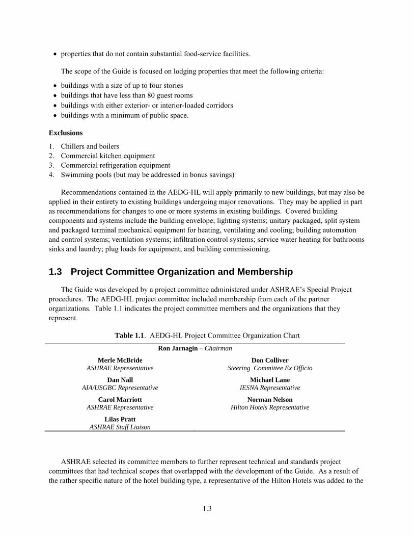
The Guide was developed by a project committee administered under ASHRAE’s Special Project procedures. The AEDG-HL project committee included membership from each of the partner organizations. Table 1.1 indicates the project committee members and the organizations that they represent.
Table 1.1. AEDG-HL Project Committee Organization Chart
Ron Jarnagin – Chairman
Merle McBride Don Colliver ASHRAE Representative Steering Committee Ex Officio
Dan Nall Michael Lane AIA/USGBC Representative IESNA Representative
Carol Marriott Norman Nelson ASHRAE Representative Hilton Hotels Representative
Lilas Pratt ASHRAE Staff Liaison
ASHRAE selected its committee members to further represent technical and standards project committees that had technical scopes that overlapped with the development of the Guide. As a result of the rather specific nature of the hotel building type, a representative of the Hilton Hotels was added to the

1.4
committee to provide expertise in construction and use issues related to hotels. Each of the representative organizations was given the chance to provide peer review input on the various review drafts produced by the project committee. In effect, these representatives were intended to be the interface to their respective organizations to ensure a large body of input into development of the document.

2.1
2.0 AEDG-HL Development Schedule and Milestones
Following the guidance from the steering committee, the AEDG-HL project committee developed a 7-month plan for completing the document. Key milestones in the development schedule center around the review periods for the various completion stages for the draft document. Utilizing a similar schedule to what was developed for the most recent guides for retail and warehouse, the project committee planned for two peer-review periods that corresponded with a 65% completion draft (technical refinement review) and a 90% completion draft (final review for errors). During development of the initial guide for small offices, an earlier 35% review period was held to gain input on the conceptual approach for the guides. Since then, four guides have been published following a consistent format, and the steering committee felt that a conceptual review was no longer needed.
Because the document was developed under the ASHRAE Special Project procedures, and not the standards development procedures, the reviews were not considered true “public” reviews. However, review copies were made available to all of the partner organizations, as well as the various bodies within ASHRAE represented by the membership on the project committee. In addition, interested members could download review copies from the ASHRAE web site. Table 2.1 outlines key dates in the development of the AEDG-HL.
Table 2.1. AEDG-HL Key Development Dates
Date Event Comment 3/1 – 3/2/2008 Project Committee Meeting #1 Initial organizational meeting 4/25 – 4/26/2008 Project Committee Meeting #2 Review simulation results, prepare 65% draft 5/12 – 5/23/2008 65% Draft Review Period Milestone #1 6/7 – 6/8/2008 Project Committee Meeting #3 Address peer review remarks on 65% draft,
review simulation results, work on 90% draft 7/14 – 7/25/2008 90% Draft Review Period Milestone #2 8/15 – 8/16/2008 Project Committee Meeting #4 Address peer review remarks on 90% draft,
review simulation results and complete 100% review draft
Late Sep 2008 Transfer final draft to steering committee
Milestone #3
October 2008 Conference call Steering committee approval of final draft

3.1
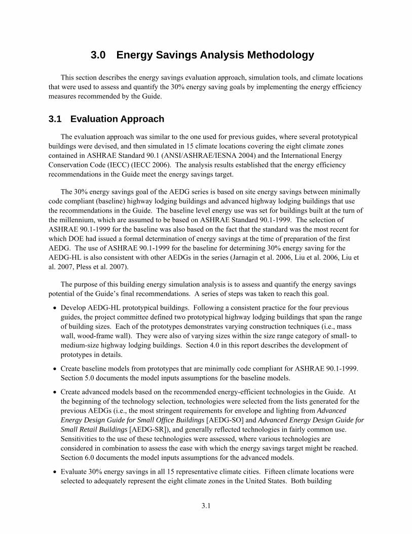
3.0 Energy Savings Analysis Methodology
This section describes the energy savings evaluation approach, simulation tools, and climate locations that were used to assess and quantify the 30% energy saving goals by implementing the energy efficiency measures recommended by the Guide.
3.1 Evaluation Approach
The evaluation approach was similar to the one used for previous guides, where several prototypical buildings were devised, and then simulated in 15 climate locations covering the eight climate zones contained in ASHRAE Standard 90.1 (ANSI/ASHRAE/IESNA 2004) and the International Energy Conservation Code (IECC) (IECC 2006). The analysis results established that the energy efficiency recommendations in the Guide meet the energy savings target.
The 30% energy savings goal of the AEDG series is based on site energy savings between minimally code compliant (baseline) highway lodging buildings and advanced highway lodging buildings that use the recommendations in the Guide. The baseline level energy use was set for buildings built at the turn of the millennium, which are assumed to be based on ASHRAE Standard 90.1-1999. The selection of ASHRAE 90.1-1999 for the baseline was also based on the fact that the standard was the most recent for which DOE had issued a formal determination of energy savings at the time of preparation of the first AEDG. The use of ASHRAE 90.1-1999 for the baseline for determining 30% energy saving for the AEDG-HL is also consistent with other AEDGs in the series (Jarnagin et al. 2006, Liu et al. 2006, Liu et al. 2007, Pless et al. 2007).
The purpose of this building energy simulation analysis is to assess and quantify the energy savings potential of the Guide’s final recommendations. A series of steps was taken to reach this goal.
• Develop AEDG-HL prototypical buildings. Following a consistent practice for the four previous guides, the project committee defined two prototypical highway lodging buildings that span the range of building sizes. Each of the prototypes demonstrates varying construction techniques (i.e., mass wall, wood-frame wall). They were also of varying sizes within the size range category of small- to medium-size highway lodging buildings. Section 4.0 in this report describes the development of prototypes in details.
• Create baseline models from prototypes that are minimally code compliant for ASHRAE 90.1-1999. Section 5.0 documents the model inputs assumptions for the baseline models.
• Create advanced models based on the recommended energy-efficient technologies in the Guide. At the beginning of the technology selection, technologies were selected from the lists generated for the previous AEDGs (i.e., the most stringent requirements for envelope and lighting from Advanced Energy Design Guide for Small Office Buildings [AEDG-SO] and Advanced Energy Design Guide for Small Retail Buildings [AEDG-SR]), and generally reflected technologies in fairly common use. Sensitivities to the use of these technologies were assessed, where various technologies are considered in combination to assess the ease with which the energy savings target might be reached. Section 6.0 documents the model inputs assumptions for the advanced models.
• Evaluate 30% energy savings in all 15 representative climate cities. Fifteen climate locations were selected to adequately represent the eight climate zones in the United States. Both building
3.2
prototypes were rotated for two different orientations during energy simulation, and the energy savings target was evaluated based on the worst scenario between the two orientations. The summary of energy simulation results for all locations and the final energy saving recommendations by climate zones are described in Section 8.0.
• Finally, the energy savings of the prescriptive recommendations were also examined relative to ANSI/ASHRAE/IESNA Standard 90.1-2004 (ANSI/ASHRAE/IESNA 2004) and the saving results were also documented in Section 8.2 in this report.
3.2 Simulation Tool Description
EnergyPlus Version 2.2 (released in April 2008) was used to assess the energy savings potential of recommended energy efficiency measures, and to perform analysis of the final recommendations in the Guide. EnergyPlus is a new building energy simulation program under development by DOE since 1996 (DOE 2008). It is a complex building energy simulation program for modeling building heating, cooling, lighting, ventilating, and other energy flows. While it is based on the most popular features and capabilities of BLAST and DOE-2, EnergyPlus includes many innovative simulation capabilities, such as time steps of less than 1 hour, modular systems and plants integrated with heat balance-based zone simulation, multi-zone air flow, thermal comfort, and renewable energy systems. EnergyPlus is a heavily tested program with formal validation efforts repeated for every release1.
All energy simulations were completed with Pacific Northwest National Laboratory’s (PNNL) Linux energy simulation infrastructure that manages inputs and outputs of the EnergyPlus simulations. This infrastructure includes creating EnergyPlus input files by a PNNL-developed program known as gparm, submitting input files to a 50-Central Processing Unit (CPU) computing cluster for batch simulation, and energy end-use results extraction.
3.3 Selection of Climate Locations for Final Guide
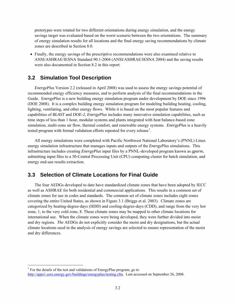
The four AEDGs developed to date have standardized climate zones that have been adopted by IECC as well as ASHRAE for both residential and commercial applications. This results in a common set of climate zones for use in codes and standards. The common set of climate zones includes eight zones covering the entire United States, as shown in Figure 3.1 (Briggs et al. 2003). Climate zones are categorized by heating-degree-days (HDD) and cooling-degree-days (CDD), and range from the very hot zone, 1, to the very cold zone, 8. These climate zones may be mapped to other climate locations for international use. When the climate zones were being developed, they were further divided into moist and dry regions. The AEDGs do not explicitly consider the moist and dry designations, but the actual climate locations used in the analysis of energy savings are selected to ensure representation of the moist and dry differences.
1 For the details of the test and validations of EnergyPlus program, go to http://apps1.eere.energy.gov/buildings/energyplus/testing.cfm. Last accessed on September 26, 2008.

3.3
Figure 3.1. DOE-Developed Climate Zone Map
When the climate zones were being developed, specific climate locations (cities) were selected as being most representative of each of the climate zones. These representative climate locations were assigned construction weights based on using population from the U.S. Geologic Service’s (USGS) Populated Places dataset as a surrogate for construction volume mapped to each climate location (USGS 2006). The weighted climate locations can then be used to aggregate savings results for the purpose of calculating national weighted energy savings. The 15 climate cities representative of the 8 climate zones are listed below:
• Zone 1A: Miami, Florida (hot, humid) • Zone 2A: Houston, Texas (hot, humid) • Zone 2B: Phoenix, Arizona (hot, dry) • Zone 3A: Memphis, Tennessee (hot, humid) • Zone 3B: El Paso, Texas (hot, dry) • Zone 3C: San Francisco, California (marine) • Zone 4A: Baltimore, Maryland (mild, humid) • Zone 4B: Albuquerque, New Mexico (mild, dry) • Zone 4C: Seattle, Washington (marine) • Zone 5A: Chicago, Illinois (cold, humid) • Zone 5B: Boise, Idaho (cold, dry) • Zone 6A: Burlington, Vermont (cold, humid) • Zone 6B: Helena, Montana (cold, dry) • Zone 7: Duluth, Minnesota (very cold) • Zone 8: Fairbanks, Alaska (extremely cold).
3.4
The map in Figure 3.2 indicates the 15 climate locations chosen for the analysis of the guides.
Figure 3.2. Map of Climate Locations
4.1
4.0 Development of Prototypical Buildings
The first step of the energy savings analysis is the development of prototypical buildings. This section describes currently available data sources representing highway lodging new constructions as well the existing building stock. The process of how the characteristics of highway lodging prototypes were developed is also documented. Tables B.1 and B.2 in Appendix B summarize the building characteristics for the highway lodging prototypes. These assumptions were used for developing baseline building models and advanced building models, which are described in Section 5.0 and 6.0, respectively.
4.1 Data Sources
The data sets that were used to help form the highway lodging building prototypes for the energy analysis include the following:
• the 2003 Commercial Building Energy Consumption Survey (2003 CBECS) (EIA 2006) 1
• the F.W. Dodge Database2
• New Commercial Construction Characteristics (NC3) Database 3
• the 2007 Lodging Industry Profile (AHLA 2007)
• additional data sets from the AEDG-HL project committee, including actual floor flans for Hampton Inn Prototype (Hampton Inn 2008), plug loads, and so on.
The CBECS data sets are publicly available and provide statistically valid results from a periodic national survey of commercial buildings and their energy suppliers performed by EIA. While the Guide is used for new constructions, some building characteristics in new constructions are almost the same as existing constructions. Furthermore, it can provide information about common characteristics of highway lodging buildings, which is critical to the prototypical building development. In the 2003 CBECS survey, 4,859 buildings were surveyed, and the sampled buildings were given base weights (CBECS variable “ADJWT8”) to represent the entire stock of commercial buildings in the United States. The 2003 CBECS contains a total of 260 surveyed lodging buildings, separated into four sub-categories: 1) hotel, 2) motel or inn, 3) dormitory/fraternity/sorority, and 4) other lodging.
F.W. Dodge Database provides detailed historical and forecast databases of construction activity. It contains extensive, comprehensive coverage of existing building space throughout the United States. Up to 20 years of historical data is combined with up to 25 years of forecast data for 15 different project types. Details include floor space, number of buildings, and so on.
NC3 is an internal PNNL database of nationwide commercial construction energy-related characteristics developed based on building characteristics taken from McGraw Hill/F.W. Dodge
1 The results of the 2003 CBECS surveys are available as downloadable reports and micro-data files from the EIA website (http://www.eia.doe.gov/emeu/cbecs/). The 2003 CBECS is the most recent data set available. 2 http://dodge.construction.com/analytics/MarketMeasurement/BuildingStockDatabase.asp 3 National Commercial Construction Characteristics Database (NC3), an internal database developed by Pacific Northwest National Laboratory with DOE Building Technologies Program support to represent nationwide commercial construction energy-related characteristics.
4.2
commercial building plans submitted for construction bids (Richman et al. 2008). The current database includes over 300 commercial buildings.
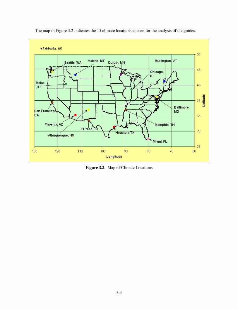
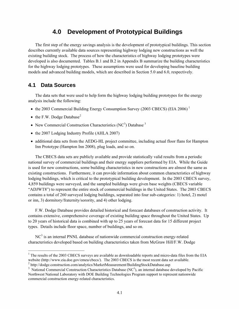
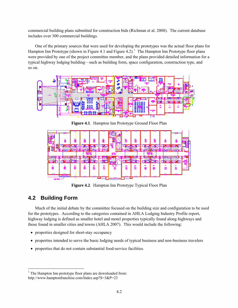
One of the primary sources that were used for developing the prototypes was the actual floor plans for Hampton Inn Prototype (shown in Figure 4.1 and Figure 4.2).1 The Hampton Inn Prototype floor plans were provided by one of the project committee member, and the plans provided detailed information for a typical highway lodging building—such as building form, space configuration, construction type, and so on.
Figure 4.1. Hampton Inn Prototype Ground Floor Plan
Figure 4.2. Hampton Inn Prototype Typical Floor Plan
4.2 Building Form
Much of the initial debate by the committee focused on the building size and configuration to be used for the prototypes. According to the categories contained in AHLA Lodging Industry Profile report, highway lodging is defined as smaller hotel and motel properties typically found along highways and those found in smaller cities and towns (AHLA 2007). This would include the following:
• properties designed for short-stay occupancy
• properties intended to serve the basic lodging needs of typical business and non-business travelers
• properties that do not contain substantial food-service facilities.
1 The Hampton Inn prototype floor plans are downloaded from: http://www.hamptonfranchise.com/Index.asp?S=3&P=23

4.3
Based on the scoping document from the steering committee, the project committee decided that the scope of the Guide specifically covers hotels up to 80 rooms, typically four stories or less, that use unitary heating and air-conditioning equipment. Following a consistent practice for the four previous guides, the 30% energy savings target was evaluated based on two prototypes (i.e., a small highway lodging prototype and a large highway lodging prototype) representing low-end and high-end highway lodging, respectively.
The 2003 CBECS was the primary source used to characterize the “typical” building parameters for the small highway lodging prototype. This includes building square footage, number of floors, building shape, etc. The F.W. Dodge Database for new constructions as well as the actual floor plans for the Hampton Inn Prototype was used for developing the large highway lodging prototype.
The characterization of small highway lodging prototype was based on a subset of hotel/motel buildings in 2003 CBECS, which have less than 80 guest rooms. The 2003 CBECS data report that the weighted average floor area for highway lodging buildings is 13,817 ft2. This yielded the small highway lodging prototype design that was approximately 14,000 ft2 in size. The 2003 CBECS also reports that 50% of the highway lodging buildings are two-story buildings, and 33% of the buildings are one-story buildings, as shown in Figure 4.3.
The CBECS survey asks questions about building shape (square, wide rectangle, “L” shape, other) and the data report that about 53% of hotel/motel buildings that have less than 80 rooms are wide rectangular shape and 18% of highway lodging buildings are “L” shape (shown in Figure 4.4). Therefore, the committee assumed the small highway lodging prototype to be a wide rectangle and two-story building.
0%
10%
20%
30%
40%
50%
60%
1 2 3 4 5
Wei
ghte
d A
vera
ge N
umbe
r of B
uild
ings
(%)
Figure 4.3. Building Number of Floors Distribution in 2003 CBECS (for Motel/Hotel with Less than 80
Rooms)

4.4
0%
10%
20%
30%
40%
50%
60%
"+" o
r cro
ss sh
aped
"E" s
haped
"L" s
haped
"U" s
haped
Narrow re
ctangle
Other
shap
e
Rectan
gle/sq
uare w
ith co
urtya
rdWide
recta
ngle
Square
Wei
ghte
d A
vera
ge N
umbe
r of B
uild
ings
(%)
Figure 4.4. Building Shape Distribution in 2003 CBECS (for Motel/Hotel with Less than 80 Rooms)
The floor plan of the small highway lodging prototype was assumed by the committee based on the typical guest room size as well as the typical guest room configuration. The typical room size was assumed to be 288 ft2 (12 ft by 24 ft), which was very close to what was shown in NC3 Database floor plan (i.e., 280 ft2 for standard guest room in Sleep Inn prototype). This yielded that the small highway lodging prototype had 44 guest rooms. The committee also assumed that floor-to-ceiling height was 9 ft. A low-end highway lodging building usually has an exterior-loaded corridor and has very limited public space. Therefore, the small highway lodging prototype was assumed to have an exterior corridor, and 90% of the floor area was guest room space. Table 4.1 summarizes all the space types in this prototype as well as the floor area percentage for each space type. Both the exterior view and the floor plan for the small highway lodging prototype are shown in Figure 4.5.
Table 4.1. Space Type for Small Highway Lodging Prototype
Space Type Floor Area Percentage
Guest Rooms 90% Office 5% Laundry 5% Total Floor Area 100%

4.5
Figure 4.5. Exterior View and Floor Plan of the 14,000 ft² Highway Lodging Prototype
A close look at F.W. Dodge Database suggested that the majority of hotel/motel buildings from 1999 to 2005 are approximately 45,000 sf2 in size, as shown in Figure 4.6. The committee decided that the 14,000 ft2 highway lodging building represented the low-end highway lodging and decided to develop a large highway lodging prototype with floor area being approximately 45,000 ft2. One of the project member provided access to the detailed floor plans for the Hampton Inn Prototype, which was used as the base for developing the building configuration for the large highway lodging prototype. The large highway lodging prototype (Hampton Inn Prototype) was a wide, rectangular, four-story building and has 77 guest rooms, accounting for 63% of the total floor space. The size of the building was approximately 43,000 ft2. Aside from the living space, it also had a relatively larger public space, compared with the small highway lodging prototype. The public space mainly contained lobby, office, corridor, meeting room, laundry room, exercise room, etc. Table 4.2 summarizes all the space types in this prototype as well as the floor area percentage for each space type. Based on the floor plans, it was assumed that the floor-to-ceiling height was 11 ft for the ground floor and 9 ft for the second through the fourth floor. Figure 4.7 shows the exterior view and floor plan for this prototype.
Figure 4.6. Hotel/Motel Building Number vs. Floor Area Distribution from F.W. Dodge Database

4.6
Table 4.2. Space Type for Large Highway Lodging Prototype
Space Type Floor Area Percentage Guest Rooms 63% Corridor 13% Lobby/Lounge 4% Stairs 4% Storage 3% Office/Reception 3% Meeting Room 2% Laundry Room 2% Elevator 2% Employee Lounge 1% Restrooms 1% Exercise Room 1% Mechanical Room 1% Total Floor Area 100%
Ground Floor Typical Floor
Figure 4.7. Exterior View and Floor Plans of the 43,000ft² Highway Lodging Prototype
4.3 Envelope Construction
The description of the wall construction and roof construction variables in 2003 CBECS primarily describes the surface material for these portions of the building envelope and not the actual construction. The most common opaque wall-surface material category for hotel/motel buildings that have less than 80 rooms in 2003 CBECS is “brick, stone, or stucco,” about 48% of the buildings as shown in Figure 4.8. The most common roof category for hotel/motel buildings that have less than 80 rooms in 2003 CBECS is “asphalt/fiberglass/other shingles,” about 59% of the buildings as shown in Figure 4.9.

4.7
Based on the CBECS data, the committee assumed that the wall construction and roof construction in the simulated small highway lodging prototypical building (14,000 ft²) were wood-frame wall and attic roof, respectively.
0%
10%
20%
30%
40%
50%
60%
Bric
k, s
tone
,or
stu
cco
Con
cret
ebl
ock
orpo
ured
conc
rete
Pre-
cast
conc
rete
pane
ls
Sidi
ng,
shin
gles
,til
es, o
rsh
akes
Oth
er
Wei
ghte
d A
vera
ge N
umbe
r of B
uild
ings
(%)
Figure 4.8. Wall Construction Material Distribution in 2003 CBECS (for Motel/Hotel Buildings with
Less than 80 Rooms)
0%
10%
20%
30%
40%
50%
60%
70%
Asp
halt/
fiber
glas
s/ot
her
shin
gles
Bui
lt-up
Con
cret
e
Met
al s
urfa
cing
Plas
tic/ru
bber
/syn
thet
icsh
eetin
g
Slat
e or
tile
shi
ngle
s
Woo
dsh
ingl
es/s
hake
s/ot
her
woo
d
Wei
ghte
d A
vera
ge N
umbe
r of B
uild
ings
(%)
Figure 4.9. Roof Construction Material Distribution in 2003 CBECS (for Motel/Hotel Buildings with
Less than 80 Rooms)

4.8
The project committee assumed, based on experience of those in the construction industry, that the large highway lodging prototype (43,000 ft²) was typically constructed with mass wall as exterior walls, built-up roof, and slab-on-grade floors. These assumptions are also consistent with the Hampton Inn Prototype. These envelope structures represent common construction practices for highway lodging buildings in the United States.
The window size in the small highway lodging prototype was determined based on the typical window size for guest rooms in small hotel/motel buildings in construction industry practice, which was assumed to be 4 ft by 5 ft. Each of the rooms had one window, which resulted in the window-to-wall ratio (WWR) of 21%. For the large highway lodging prototype, the window size was obtained from the actual Hampton Inn Prototype floor plans, which was 5 ft by 6 ft. The WWR was calculated to be 11%. In the 2003 CBECS data, a “percent exterior glass” variable is reported for each building in one of the five bins (i.e., “10 percent or less”, “11–25 percent”, etc.). The data show that 40% of the hotel/motel buildings that have less than 80 rooms fall into “11–25 percent” category, while 37% fall in the “10% or less” category (Figure 4.10). Therefore, the assumptions of the window area for the prototypes were also consistent with CBECS data.
0%
5%
10%
15%
20%
25%
30%
35%
40%
45%
10 % or less 11 to 25 % 26 to 50 % 51 to 75 % 76 to 100 %
Wei
ghte
d A
vera
ge N
umbe
r of B
uild
ings
(%)
Figure 4.10. WWR Distribution for Motel/Hotel Buildings with Less than 80 Rooms in 2003 CBECS
The CBECS also asks whether the building has skylights. The 2003 CBECS data shows about 88% of hotel/motel buildings that have less than 80 rooms also do not have skylight. The Hampton Inn Prototype also does not have skylight. Therefore, the committee assumed that both prototypical buildings had no skylight. The committee also assumed that there was no overhang for the large prototype based on the Hampton Inn prototype. For the small prototype, it was assumed that the roof was extended to cover the exterior corridor on the second floor.
In summary, the small highway lodging prototype exterior envelope consisted of wood-framed wall construction and attic roof, and the large prototype was assumed to have mass wall and built-up roof. Glazing was distributed based on the configuration of the guest rooms, with window area being 11% to 25% of total gross wall area. Both prototypes had a slab-on-grade floor and no skylight.
4.9
4.4 Air Infiltration
Building envelope tightness is important based on its relevance to the estimation of building ventilation rates as they impact building energy use and indoor air quality. Existing data sources and literature for commercial building infiltration rates are limited. A study by Persily provided some data for the air tightness of 139 commercial and institutional buildings (Persily 1998). The study concluded that no correlations between building age and air tightness, or building type and air tightness exist. It also examined the effect of wall construction types on infiltration and found that masonry, masonry/frame, concrete, and metal buildings were similar in air tightness, while frame buildings were somewhat leakier.
In both highway lodging prototypes, it was assumed that the peak infiltration rate was 0.038 cubic foot per minute (cfm)/ft2 of the gross exterior wall based on ASHRAE Standard 90.1-1989, Section 13.7.3.2 (ASHRAE 1989). Furthermore, it was assumed that the infiltration rate fraction was 1.0 for guest rooms and 0.5 for public spaces because the heating, ventilation, and air conditioning (HVAC) systems serving these two type of spaces are different, as described in Section 4.6.
4.5 Internal Loads
Building internal loads include occupancy thermal load, lighting, and plug loads. Modeling the commercial building energy use using whole-building energy simulation tools like EnergyPlus required assumptions about the building’s internal load characteristics to establish the estimated energy use for the lighting, plug loads, and HVAC systems. This section describes the building internal load characteristics that were used to estimate the HVAC loads and schedules for the prototypical buildings.
Typically, the internal loads are represented by peak occupancy density for occupancy thermal load (in person/ft2) and peak power density (in W/ft2) for lighting and plug loads and a schedule that describes the hourly magnitude (usually given in terms of fractions of the peak). These fractions multiplied by the peak load density give the actual load density for each hour. Because the lodging buildings usually have multiple space types with different functions, space-by-space method was used to determine the peak internal loads densities and load schedules.
4.5.1 People
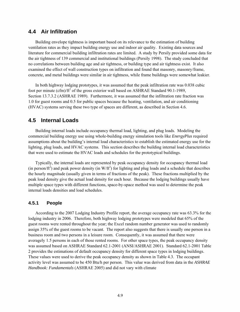
According to the 2007 Lodging Industry Profile report, the average occupancy rate was 63.3% for the lodging industry in 2006. Therefore, both highway lodging prototypes were modeled that 65% of the guest rooms were rented throughout the year; the Excel random number generator was used to randomly assign 35% of the guest rooms to be vacant. The report also suggests that there is usually one person in a business room and two persons in a leisure room. Consequently, it was assumed that there were averagely 1.5 persons in each of those rented rooms. For other space types, the peak occupancy density was assumed based on ASHRAE Standard 62.1-2001 (ANSI/ASHRAE 2001). Standard 62.1-2001 Table 2 provides the estimations of default occupancy density for different space types in lodging buildings. These values were used to derive the peak occupancy density as shown in Table 4.3. The occupant activity level was assumed to be 450 Btu/h per person. This value was derived from data in the ASHRAE Handbook: Fundamentals (ASHRAE 2005) and did not vary with climate
4.10
Table 4.3. Peak Occupancy Density by Space Type
Space Type Occupancy Peak Density
(persons/space) Guest room 1.5 Corridor/Stairs/ Restroom/Mechanical room/Storage/Elevator 0 Lobby 53 Storage 0 Office 10 Laundry 11 Meeting room 43 Exercise room 11 Employee lounge 11
4.5.2 Plug Loads
Commercial buildings generally have substantial plug loads, which increase the electrical energy use of the building. Plug loads also contribute to the cooling load of the commercial buildings, while offsetting the heating load. Plug loads represent electrical appliances operated in the conditioned space, such as TV, microwave, coffee maker, and other equipment plugged into electrical outlets, hence the name “plug load.” In some cases, plug loads might be directly wired into the electrical circuit (e.g., small motors).
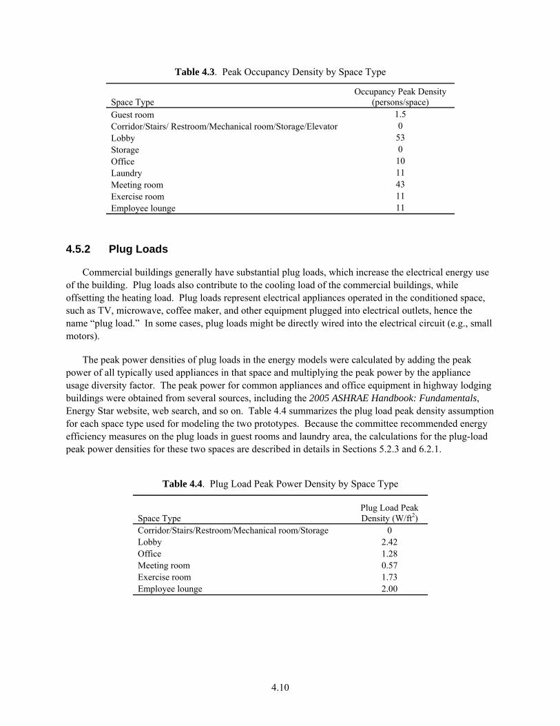
The peak power densities of plug loads in the energy models were calculated by adding the peak power of all typically used appliances in that space and multiplying the peak power by the appliance usage diversity factor. The peak power for common appliances and office equipment in highway lodging buildings were obtained from several sources, including the 2005 ASHRAE Handbook: Fundamentals, Energy Star website, web search, and so on. Table 4.4 summarizes the plug load peak density assumption for each space type used for modeling the two prototypes. Because the committee recommended energy efficiency measures on the plug loads in guest rooms and laundry area, the calculations for the plug-load peak power densities for these two spaces are described in details in Sections 5.2.3 and 6.2.1.
Table 4.4. Plug Load Peak Power Density by Space Type
Space Type Plug Load Peak Density (W/ft2)
Corridor/Stairs/Restroom/Mechanical room/Storage 0 Lobby 2.42 Office 1.28 Meeting room 0.57 Exercise room 1.73 Employee lounge 2.00
4.11
The electricity consumption of the elevators in large highway lodging prototype was derived based on the study by Sachs (Sachs 2005). The study suggests that a light-loaded low-rise hydraulic elevator doing 100,000 starts (door openings) consumes 1,900 kWh per year. Therefore, in the large highway lodging prototype, the elevators consume about 4,161 kWh per year, assuming that there are 100 persons in the building and each person has six runs per day.
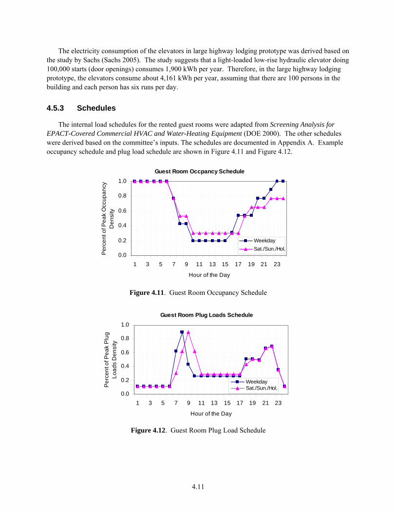
4.5.3 Schedules
The internal load schedules for the rented guest rooms were adapted from Screening Analysis for EPACT-Covered Commercial HVAC and Water-Heating Equipment (DOE 2000). The other schedules were derived based on the committee’s inputs. The schedules are documented in Appendix A. Example occupancy schedule and plug load schedule are shown in Figure 4.11 and Figure 4.12.
Guest Room Occpancy Schedule
0.0
0.2
0.4
0.6
0.8
1.0
1 3 5 7 9 11 13 15 17 19 21 23
Hour of the Day
Per
cent
of P
eak
Occ
upan
cy
Den
sity
WeekdaySat./Sun./Hol.
Figure 4.11. Guest Room Occupancy Schedule
Guest Room Plug Loads Schedule
0.0
0.2
0.4
0.6
0.8
1.0
1 3 5 7 9 11 13 15 17 19 21 23
Hour of the Day
Per
cent
of P
eak
Plu
g Lo
ads
Den
sity
WeekdaySat./Sun./Hol.
Figure 4.12. Guest Room Plug Load Schedule
4.12
4.6 HVAC System
This section describes the development of the typical heating and cooling systems used in highway lodging buildings.
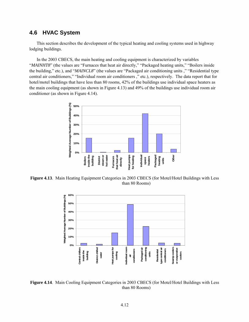
In the 2003 CBECS, the main heating and cooling equipment is characterized by variables “MAINHT8” (the values are “Furnaces that heat air directly,” “Packaged heating units,” “Boilers inside the building,” etc.), and “MAINCL8” (the values are “Packaged air conditioning units ,” “Residential type central air conditioners,” “Individual room air conditioners ,” etc.), respectively. The data report that for hotel/motel buildings that have less than 80 rooms, 42% of the buildings use individual space heaters as the main cooling equipment (as shown in Figure 4.13) and 49% of the buildings use individual room air conditioner (as shown in Figure 4.14).
0%
10%
20%
30%
40%
50%
Boi
lers
insi
de th
ebu
ildin
g
Dis
trict
stea
m o
rho
t wat
er
Furn
aces
that
hea
t air
dire
ctly
Hea
t pum
psfo
r hea
ting
Indi
vidu
alsp
ace
heat
ers
Pack
aged
heat
ing
units Oth
erWei
ghte
d A
vera
ge N
umbe
r of B
uild
ings
(%)
Figure 4.13. Main Heating Equipment Categories in 2003 CBECS (for Motel/Hotel Buildings with Less
than 80 Rooms)
0%
10%
20%
30%
40%
50%
60%
Cen
tral
chi
llers
insi
de th
ebu
ildin
g
Dis
tric
t chi
lled
wat
er
Hea
t pum
ps fo
rco
olin
g
Indi
vidu
al ro
omai
rco
nditi
oner
s
Pack
aged
air
cond
ition
ing
units
Res
iden
tial
type
cen
tral
air
cond
ition
ers
Swam
p co
oler
sor
eva
pora
tive
cool
ers
Wei
ghte
d A
vera
ge N
umbe
r of B
uild
ings
(%)
Figure 4.14. Main Cooling Equipment Categories in 2003 CBECS (for Motel/Hotel Buildings with Less than 80 Rooms)

4.13
Unfortunately, not all the 2003 CBECS responses regarding equipment categories are mutually exclusive, particularly in the categories of packaged heating units, individual space heaters, packaged air conditioning units, individual room air conditioners, and heat pumps; the sum of the percentage of which is 78% for the main heating equipment and 87% for the main cooling equipment for the hotel/motel buildings that have less than 80 rooms. Based on the inputs from the lodging industry experts, the most typical heating and cooling system used in guest rooms in highway lodging is packaged terminal air conditioner (PTAC) and packaged terminal heat pump (PTHP); and the typical heating and cooling system used in public spaces is a split air conditioner system. Both of these systems can be categorized as packaged heating units (or individual space heaters for heating) and packaged air conditioning units (or individual room air conditioner for cooling), thus consistent with the CBECS statistic data. Review of the NC3 database also suggests that PTACs and PTHPs are commonly used in the guests’ rooms and split system is commonly used in public spaces for small hotels and motels.
Furthermore, the Ducker’s PTAC market research report (Ducker Worldwide 2001) reveals that hotels/motels are the biggest end users of PTAC and PTHP, accounting for 70% of the PTAC and PTHP market. More-detailed market data shows that among the four major sizes of PTAC, (7 kBtu/h, 9 kBtu/h, 12 kBtu/h, and 15 kBtu/h), the PTAC and PTHP of 9 kBtu/h capacity accounts for approximately 50% of the U.S. PTAC and PTHP market in year 2000.
In summary, it was assumed that the guest rooms in both highway lodging prototypes were served by PTAC and PTHP with 9 kBtu/h cooling capacity, and the public spaces in the large prototype were served by split air conditioning systems. Considering that the area of the public spaces (office and laundry) in the small highway lodging prototype was very small (10%), PTAC and PTHP was also used to serve the public spaces. The project committee also decided to use unit heaters to condition the semi-heated spaces, such as stairs, in the large prototype. Heating and cooling equipment operation schedules were developed based on occupancy hours, which was 24/7. Assumptions for system operation controls are described in Sections 5.0 and 6.0.
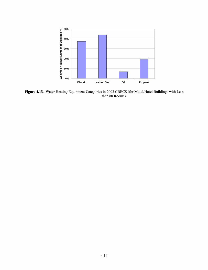
4.7 Service Water Heating System
The project committee defined the service hot water system for both highway lodging prototypes as gas-fired storage water heaters with hot water recirculation loop. Gas storage water heaters were chosen based on the inputs from the lodging industry experts as well as the 2003 CBECS data, which shows the most typical fuel used for water heating in hotels/motels with less than 80 rooms is natural gas (Figure 4.15).
4.14
0%
10%
20%
30%
40%
50%
Electric Natural Gas Oil Propane
Wei
ghte
d A
vera
ge N
umbe
r of B
uild
ings
(%)
Figure 4.15. Water Heating Equipment Categories in 2003 CBECS (for Motel/Hotel Buildings with Less
than 80 Rooms)
5.1
5.0 Development of Baseline Building Model and Assumptions
This section contains a topic-by-topic review of baseline building models and how the baseline building characteristics were assumed in the EnergyPlus modeling, including building envelope; building internal loads; HVAC equipment efficiency, operation, control, and sizing; fan power assumptions; and service water heating. A summary of these assumptions is presented in Appendix C. The use of specific trade names in this document does not constitute an endorsement of these products. It only documents the equipment that was used in the analysis for research purposes.
To quantify the expected energy savings, the baseline building models of the highway lodging prototypes were selected by the project committee to meet the prescriptive criteria of ASHRAE Standard 90.1-1999 (i.e., Section 5 through 10 in the Standard). The Standard provides the fixed reference point based on the Standard 90.1-1999 at the turn of the millennium for all guides in this series. The primary reason for this choice as the reference point is to maintain a consistent baseline and scale for all the 30% AEDG-series documents. A shifting baseline (i.e., use ASHRAE Standard 90.1-2004 as the baseline) between multiple documents in the AEDG series would lead to confusion among users about the level of energy savings achieved. In addition, the 1999 Standard is the latest version of ASHRAE Standard 90.1 upon which DOE has published its determination in the Federal Register when this Guide was developed. This determination concluded that Standard 90.1-1999 would improve commercial building energy efficiency by comparing it to Standard 90.1-1989, fulfilling DOE's mandate under the Energy Conservation Policy Act, as amended.
5.1 Envelope
The project committee assumed that the small highway lodging prototype (14,000 ft²) was constructed with wood-framed exterior walls, attic roofs, and slab-on-grade floors. For the large highway lodging prototype (43,000 ft²), mass exterior walls, built-up roofs, and slab-on-grade floors were assumed. These envelope structures represent common construction practices for small- to medium-size highway lodging buildings in the United States.
The baseline building envelope characteristics were developed to meet the prescriptive design option requirements in accordance with ASHRAE Standard 90.1-1999 Section 5.3. Different from the building types covered in the previous guides, most of the spaces in lodging buildings are guest rooms, which are defined as residential spaces according to the Standard. Because 90% of the space area on both floors in the small highway lodging building prototype is guest rooms, it was decided that the entire building envelope of the small prototype shall meet the requirements for residential conditioned space. For the large highway lodging prototype, 84% of the spaces on the ground floor are non-residential spaces and 79% of the spaces on the rest of floors are guest rooms. Therefore, it was decided that the envelope requirements for the spaces on the ground floor shall meet the criteria for non-residential conditioned space, and the envelope requirements for the spaces on the remaining floors shall meet the criteria for residential conditioned space. The following section describes the assumptions used for modeling the baseline building envelope construction, including the exterior walls, roofs, slab-on-grade floors, window glazing, and doors.

5.2
Layer-by-layer descriptions of the constructions of exterior surfaces were used to model the building thermal envelope in EnergyPlus. This method allowed for properly account for thermal mass impacts on the space loads.
5.1.1 Exterior Walls
Two types of exterior walls were modeled in this analysis work (i.e., wood-framed walls for the small highway lodging building and mass walls for the large highway lodging building). Wood-framed exterior walls were assumed to have a standard framing configuration (i.e., 2 in. × 4 in. wood stud framing at 16-in. [inch] on center with cavities filled with 14.5- in. wide insulation for 3.5-in. deep wall cavities). The overall U-factor was calculated based on the weighting factor of 75% insulated cavity; 21% of wood studs, plates, and sills; and 4% of wood headers, in accordance with A3.4 (a) in the Standard. The wood-framed wall includes the following layers:
• outside air film (calculated by EnergyPlus) • 1-in. exterior stucco (R-0.08) • 0.625-in. gypsum board (R-0.56) • cavity insulation (R-value varies by climate) • wood studs or wood headers (R-4.38) • additional board insulation (R-value varies by climate) • 0.625-in. thick gypsum board (R-0.56) • inside air film (calculated by EnergyPlus).
The mass wall was assembled assuming 8-in. medium weight concrete blocks with a density of 115 lb/ft³ and solid grouted cores (refer to Table A-5 in the Standard). The mass wall includes the following layers:
• outside air film (calculated by EnergyPlus) • 8-in. concrete block, 115 lb/ft³ (R-0.87) • 1-in. metal clips with rigid insulation (R-value varies by climate) • 0.5-in. gypsum board (R-0.45, if insulation is present) • inside air film (calculated by EnergyPlus).
R-values for most of the above layers were derived from Appendix A of the Standard (Assembly U-Factor, C-Factor, And F-Factor Determination). Insulation R-values were selected to meet the minimum R-values required in the Standard’s Appendix B (Building Envelope Criteria), as defined by climate range.
5.1.2 Roofs
An attic roof was used for the small highway lodging building. The attic roof was assumed as the roof with a standard wood framing. In accordance with A2.4 (a) in the Standard, the base attic roof assembly was a roof with a normal 4-in. deep wood as the lower chord of a roof truss or ceiling joist. The ceiling was attached directly to the lower chord of the truss and attic space above was ventilated. Insulation was located directly on top of the ceiling, first filling the cavities between the wood and then later covering both the wood and cavity areas. Insulation was tapered around the perimeter with resultant decrease in thermal resistance. The overall U-factor was determined by the weighting factor of 85% full
5.3
depth insulation, 5% half-depth insulation, and 10% wood joists, in accordance with A2.4 (a) in the Standard. For the wood joists, it was assumed that there was a 1-in. air space above the top of the wood joist until the insulation expands to the full cavity width, based on the inputs from the project committee. The attic roof includes the following layers:
• outside air film (calculated by EnergyPlus) • full-depth cavity insulation (R-value varies by climate) • half-depth cavity insulation (R-value varies by climate) • 1-in. air space above wood joists (R-0.9) • wood joists (R-4.38) • 0.625-in. gypsum board (R-0.56) • inside air film (calculated by EnergyPlus).
Built-up roofs were modeled in the large highway lodging building (i.e., rigid insulation over a structural metal deck). The minimum U-factor includes R-0.17 for exterior air film, R-0 for metal deck, and R-0.61 for interior air film heat flow up. Added insulation is continuous and uninterrupted by framing. Roof insulation R-values were also set to match the minimum roof insulation requirements for residential space in Appendix B (Building Envelope Criteria) of the Standard, by climate.
The Standard does not specify either absorptance or other surface assumptions. In the baseline prototypes, the roof exterior finish was chosen as medium brown asphalt shingles for the attic roof and a single-ply roof membrane with grey EPDM (ethylene-propylenedieneterpolymer membrane) for the built-up roof, respectively. From a cool roofing materials database developed by the Lawrence Berkeley National Laboratory (LBNL 2000), the solar reflectance of the medium brown asphalt shingles was assumed to be 0.12, and the corresponding emissivity was 0.91. The solar reflectance of a grey EPDM was assumed to be 0.23, and the corresponding emissivity was assumed to be 0.87, derived from a study by Pacific Gas and Electric Company (PG&E) (Eilert 2000).
5.1.3 Slab-On-Grade Floors
Slab-on-grade floors were assumed for both prototypical buildings. The base assembly for the slab-on-grade floor is a slab floor of 6-in. concrete poured directly onto the earth. The bottom of the slab is 12-in. soil, with soil conductivity of 0.75 Btu/hr-ft²-°F. In contrast to the U-factor requirements for other envelope assemblies, the F-factor is set to match the minimum requirements for slab-on-grade floors for residential space in Appendix B of the Standard, based on climate. F-factor is expressed as the conductance of the surface per unit length of building perimeter, in the unit of Btu/hr-°F-ft. Appendix B of the Standard also provides the corresponding R-values of the vertical insulation when required by the Standard. This continuous insulation is typically applied directly to the slab exterior surface, extending downward from the top of the slab for the distance specified.
One of the advanced features in EnergyPlus program is that the calculation of ground-heat transfer through ground-contact surfaces (i.e., slab-on-grade floors) is two- or three- dimensional rather than the simplified one-dimensional used in DOE-2 program (LBNL 2004). To use this method, the appropriate ground temperatures under the slab were first calculated by using the Slab program, a preprocessor as part of the auxiliary EnergyPlus programs. Then, the calculated custom monthly average ground temperatures were transferred into the main EnergyPlus program as one of the building energy model inputs.
5.4
In the Slab program, the key inputs to calculate the ground temperatures are described as following:
• slab material and soil density • building height • indoor average temperature set point • R-value and depth of vertical insulation (if presented) • thickness of slab-on-grade • the floor area to perimeter length ratio for this slab • distance from edge of slab to domain edge.
For the baseline models, the Slab program was used to run a simple building with the above parameters defined in each of the 15 climate locations. The slab insulations requirements were obtained from the Standard. The Slab program outputs perimeter ground monthly temperatures, core ground monthly temperatures, and average monthly temperatures. For this analysis, the average monthly temperatures were used as the inputs for the ground temperatures under the floor slab in the EnergyPlus input files.
5.1.4 Fenestration
The window size in the small highway lodging prototype was determined based on the typical window size for guest rooms in small hotels/motels, which was assumed to be 4 ft by 5 ft. Each of the rooms had one window, which resulted in the WWR being 21%. For the large highway lodging prototype, the window size was obtained from the actual Hampton Inn Prototype floor plans, which was 5 ft by 6 ft. The WWR was calculated to be 11%.
Window requirements in the Standard are defined by bulk properties of U-factor and solar heat gain coefficient (SHGC). EnergyPlus, however, requires that the thermal/optical properties be defined for the window assembly layer by layer. Hypothetical window layers were derived by iterative Window 5 calculations within EnergyPlus to produce a match to the specified U-factor and SHGC outlined in Appendix B in the Standard, by climate. The values are summarized in Appendix C. Windows are collected into a single object, and frames are neglected to reduce complexity in the EnergyPlus models and make the simulations run faster. The window performance is modeled as for the entire glazed area. U-factor and SHGC values were treated as whole-assembly.
5.1.5 Doors
The performances of opaque doors that are exposed to outside environment were modeled to match the U-factor specified in Appendix B in the Standard, by climate, for the baseline buildings. In the EnergyPlus input files, the opaque doors were defined by R-values, which corresponded to the required U-factors.
5.1.6 Air Infiltration
The Standard does not specify the requirement for air infiltration rate. Building air infiltration is addressed indirectly in the Standard through the requirements in building envelope sealing, fenestration
5.5
and doors air leakage, etc. For this analysis, the infiltration rate was assumed to be 0.038 cfm/ft² of gross exterior wall, per ASHRAE Standard 90.1-1989.
The basic equation used to calculate infiltration in EnergyPlus is:
[ ]2)()()())(( WindSpeedDWindSpeedCTTBAFIonInfiltrati odbzonescheduledesign ++−+= (5.1)
where Idesign = maximum infiltration rate at design conditions, cfm Fschedule = infiltration schedule Tzone – Todb = the temperature difference between the outdoor and indoor air dry-bulb
temperatures, °F
To determine the coefficients A, B, and C in the above equation, air change method was used to maintain consistency with previous guides. The default coefficients in the air change method in DOE-2 are (adjusted to SI units) 0, 0, 0.224, and 0 for A, B, C, and D, respectively. These coefficients were also used in this analysis in the EnergyPlus models. With these coefficients, the summer conditions would give an infiltration factor of 0.75, and the winter conditions would give 1.34. A wind speed of 10 mph gives a factor of 1.0 for both summer and winter conditions.
In addition, infiltration schedules were also required in modeling building infiltration rate. The infiltration schedule was assumed to be 1.0 for the spaces that were served by PTACs and PTHPs, and the infiltration schedule was 0.5 for the public spaces in the large highway lodging prototype that were served by split systems because the split systems have better outside air control compared with packaged terminal units.
5.2 Internal Loads
Modeling the energy impacts of the building internal loads using the EnergyPlus program requires assumptions about the building internal loads peak densities and operation schedules. Section 4.5 describes the building internal load characteristics for the two prototypical buildings, including people, and plug loads for spaces other than guest rooms and laundry room. These assumptions are the same for both baseline buildings and advanced buildings. In the following section, the modeling assumptions for interior lighting, exterior lighting, and plug loads for guest room and laundry room are documented.
5.2.1 Interior Lighting
In lodging buildings, lighting plays a significant role in the energy consumption of the building. Lighting energy use can vary greatly depending on the nature of the spaces served and the type of lighting fixtures used in the building. Lighting for the public, back of house, and office areas many times have light sources operating 24 hours a day, unless control measures are incorporated to minimize use. Guest room lighting will normally be under the control of the guest when occupied, and set to minimal levels by housekeeping staff when the room is not occupied.
The EnergyPlus program allows the user to specify information about electric lighting system in each zone, including design power level and operation schedule, and how the heat from lights is distributed thermally. The baseline interior lighting power for each space was derived using the space-by-space
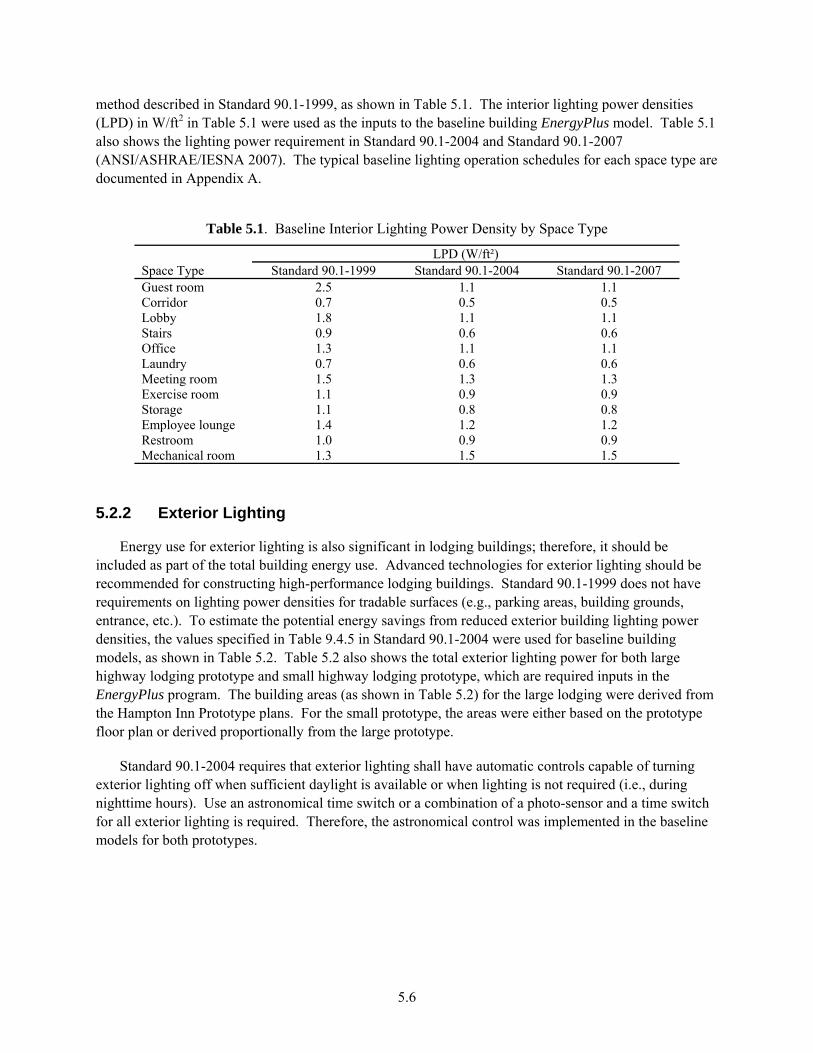
5.6
method described in Standard 90.1-1999, as shown in Table 5.1. The interior lighting power densities (LPD) in W/ft2 in Table 5.1 were used as the inputs to the baseline building EnergyPlus model. Table 5.1 also shows the lighting power requirement in Standard 90.1-2004 and Standard 90.1-2007 (ANSI/ASHRAE/IESNA 2007). The typical baseline lighting operation schedules for each space type are documented in Appendix A.
Table 5.1. Baseline Interior Lighting Power Density by Space Type
Space Type LPD (W/ft²)
Standard 90.1-1999 Standard 90.1-2004 Standard 90.1-2007 Guest room 2.5 1.1 1.1 Corridor 0.7 0.5 0.5 Lobby 1.8 1.1 1.1 Stairs 0.9 0.6 0.6 Office 1.3 1.1 1.1 Laundry 0.7 0.6 0.6 Meeting room 1.5 1.3 1.3 Exercise room 1.1 0.9 0.9 Storage 1.1 0.8 0.8 Employee lounge 1.4 1.2 1.2 Restroom 1.0 0.9 0.9 Mechanical room 1.3 1.5 1.5
5.2.2 Exterior Lighting
Energy use for exterior lighting is also significant in lodging buildings; therefore, it should be included as part of the total building energy use. Advanced technologies for exterior lighting should be recommended for constructing high-performance lodging buildings. Standard 90.1-1999 does not have requirements on lighting power densities for tradable surfaces (e.g., parking areas, building grounds, entrance, etc.). To estimate the potential energy savings from reduced exterior building lighting power densities, the values specified in Table 9.4.5 in Standard 90.1-2004 were used for baseline building models, as shown in Table 5.2. Table 5.2 also shows the total exterior lighting power for both large highway lodging prototype and small highway lodging prototype, which are required inputs in the EnergyPlus program. The building areas (as shown in Table 5.2) for the large lodging were derived from the Hampton Inn Prototype plans. For the small prototype, the areas were either based on the prototype floor plan or derived proportionally from the large prototype.
Standard 90.1-2004 requires that exterior lighting shall have automatic controls capable of turning exterior lighting off when sufficient daylight is available or when lighting is not required (i.e., during nighttime hours). Use an astronomical time switch or a combination of a photo-sensor and a time switch for all exterior lighting is required. Therefore, the astronomical control was implemented in the baseline models for both prototypes.
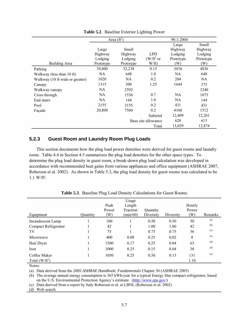
5.7
Table 5.2. Baseline Exterior Lighting Power
Building Area
Area (ft2) 90.1-2004
Large Highway Lodging Prototype
Small Highway Lodging
Prototype
LPD (W/ft2 or
W/ft)
Large Highway Lodging
Prototype (W)
Small Highway Lodging
Prototype (W)
Parking 39,800 32,238 0.15 5970 4836 Walkway (less than 10 ft) NA 648 1.0 NA 648 Walkway (10 ft wide or greater) 1020 NA 0.2 204 NA Canopy 1315 300 1.25 1644 375 Walkway canopy NA 2592 3240 Cross through NA 1536 0.7 NA 1075 End stairs NA 144 1.0 NA 144 Pool 2155 2155 0.2 431 431 Façade 20,800 7560 0.2 4160 1512
Subtotal 12,409 12,261 Base site allowance 620 613
Total 13,029 12,874
5.2.3 Guest Room and Laundry Room Plug Loads
This section documents how the plug load power densities were derived for guest rooms and laundry room. Table 4.4 in Section 4.5 summarizes the plug load densities for the other space types. To determine the plug load density in guest room, a break-down plug load calculation was developed in accordance with recommended heat gains from various appliances and office equipment (ASHRAE 2007, Roberson et al. 2002). As shown in Table 5.3, the plug load density for guest rooms was calculated to be 1.1 W/ft².
Table 5.3. Baseline Plug Load Density Calculations for Guest Rooms
Equipment Quantity
Peak Power (W)
Usage Length Fraction (min/60)
Quantity Diversity Diversity
Hourly Power (W) Remarks
Incandescent Lamp 1 100 1 0.50 0.50 50 (a)
Compact Refrigerator 1 42 1 1.00 1.00 42 (b) TV 1 75 1 0.75 0.75 56 (c) Microwave 1 400 0.08 0.25 0.02 8 (a) Hair Dryer 1 1500 0.17 0.25 0.04 63 (d) Iron 1 1000 0.25 0.15 0.04 38 (d) Coffee Maker 1 1050 0.25 0.50 0.13 131 (a) Total (W/ft2) 1.10 Notes: (a) Data derived from the 2005 ASHRAE Handbook: Fundamentals Chapter 30 (ASHRAE 2005) (b) The average annual energy consumption is 365 kWh/year for a typical Energy Star compact refrigerator, based
on the U.S. Environmental Protection Agency’s estimate. (http://www.epa.gov/) (c) Data derived from a report by Judy Roberson et al. at LBNL (Roberson et al. 2002) (d) Web search
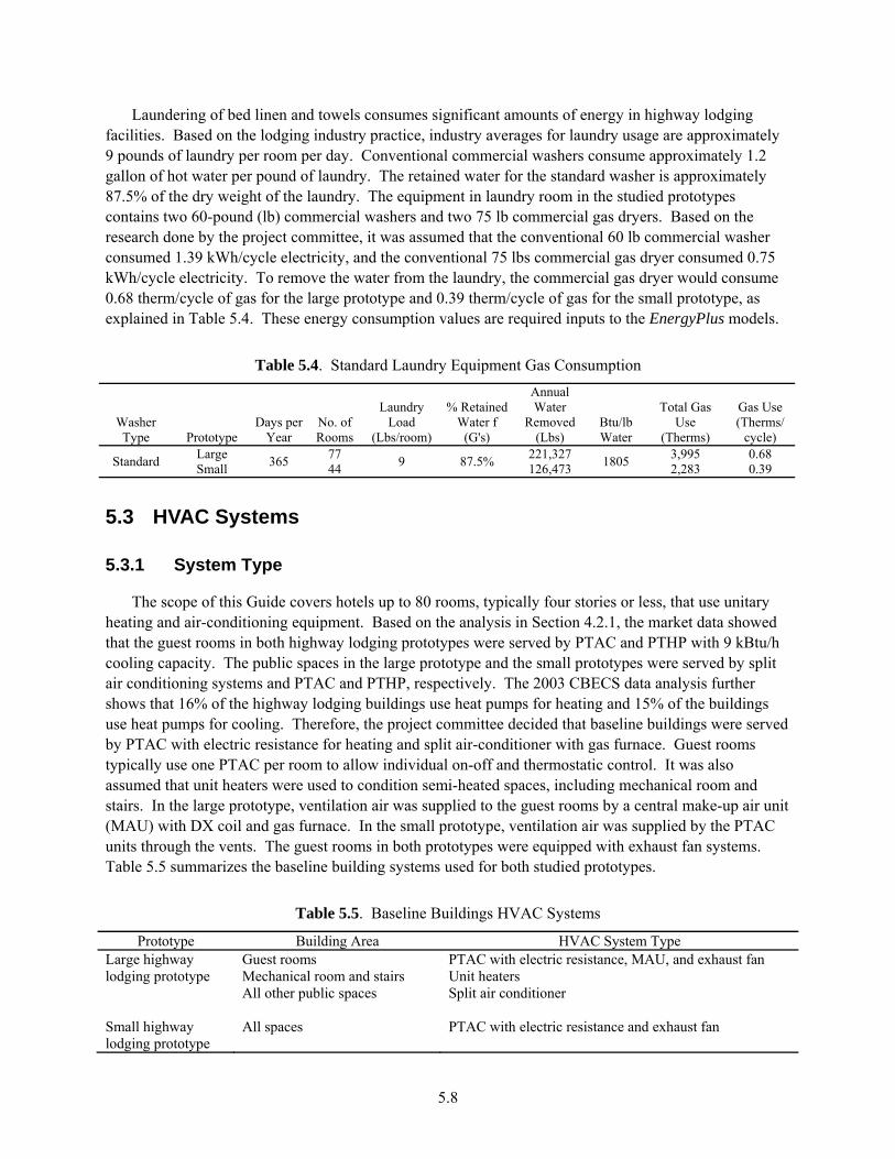
5.8
Laundering of bed linen and towels consumes significant amounts of energy in highway lodging facilities. Based on the lodging industry practice, industry averages for laundry usage are approximately 9 pounds of laundry per room per day. Conventional commercial washers consume approximately 1.2 gallon of hot water per pound of laundry. The retained water for the standard washer is approximately 87.5% of the dry weight of the laundry. The equipment in laundry room in the studied prototypes contains two 60-pound (lb) commercial washers and two 75 lb commercial gas dryers. Based on the research done by the project committee, it was assumed that the conventional 60 lb commercial washer consumed 1.39 kWh/cycle electricity, and the conventional 75 lbs commercial gas dryer consumed 0.75 kWh/cycle electricity. To remove the water from the laundry, the commercial gas dryer would consume 0.68 therm/cycle of gas for the large prototype and 0.39 therm/cycle of gas for the small prototype, as explained in Table 5.4. These energy consumption values are required inputs to the EnergyPlus models.
Table 5.4. Standard Laundry Equipment Gas Consumption
Washer Type Prototype
Days per Year
No. of Rooms
Laundry Load
(Lbs/room)
% Retained Water f
(G's)
Annual Water
Removed (Lbs)
Btu/lb Water
Total Gas Use
(Therms)
Gas Use (Therms/
cycle)
Standard Large 365 77 9 87.5% 221,327 1805 3,995 0.68 Small 44 126,473 2,283 0.39
5.3 HVAC Systems
5.3.1 System Type
The scope of this Guide covers hotels up to 80 rooms, typically four stories or less, that use unitary heating and air-conditioning equipment. Based on the analysis in Section 4.2.1, the market data showed that the guest rooms in both highway lodging prototypes were served by PTAC and PTHP with 9 kBtu/h cooling capacity. The public spaces in the large prototype and the small prototypes were served by split air conditioning systems and PTAC and PTHP, respectively. The 2003 CBECS data analysis further shows that 16% of the highway lodging buildings use heat pumps for heating and 15% of the buildings use heat pumps for cooling. Therefore, the project committee decided that baseline buildings were served by PTAC with electric resistance for heating and split air-conditioner with gas furnace. Guest rooms typically use one PTAC per room to allow individual on-off and thermostatic control. It was also assumed that unit heaters were used to condition semi-heated spaces, including mechanical room and stairs. In the large prototype, ventilation air was supplied to the guest rooms by a central make-up air unit (MAU) with DX coil and gas furnace. In the small prototype, ventilation air was supplied by the PTAC units through the vents. The guest rooms in both prototypes were equipped with exhaust fan systems. Table 5.5 summarizes the baseline building systems used for both studied prototypes.
Table 5.5. Baseline Buildings HVAC Systems
Prototype Building Area HVAC System Type Large highway lodging prototype
Guest rooms PTAC with electric resistance, MAU, and exhaust fan Mechanical room and stairs Unit heaters All other public spaces Split air conditioner
Small highway lodging prototype
All spaces
PTAC with electric resistance and exhaust fan
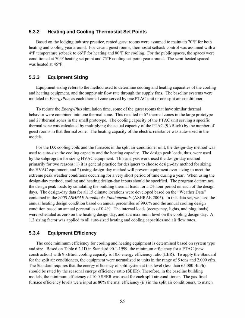
5.9
5.3.2 Heating and Cooling Thermostat Set Points
Based on the lodging industry practice, rented guest rooms were assumed to maintain 70°F for both heating and cooling year around. For vacant guest rooms, thermostat setback control was assumed with a 4°F temperature setback to 66°F for heating and 80°F for cooling. For the public spaces, the spaces were conditioned at 70°F heating set point and 75°F cooling set point year around. The semi-heated spaced was heated at 45°F.
5.3.3 Equipment Sizing
Equipment sizing refers to the method used to determine cooling and heating capacities of the cooling and heating equipment, and the supply air flow rate through the supply fans. The baseline systems were modeled in EnergyPlus as each thermal zone served by one PTAC unit or one split air-conditioner.
To reduce the EnergyPlus simulation time, some of the guest rooms that have similar thermal behavior were combined into one thermal zone. This resulted in 67 thermal zones in the large prototype and 27 thermal zones in the small prototype. The cooling capacity of the PTAC unit serving a specific thermal zone was calculated by multiplying the actual capacity of the PTAC (9 kBtu/h) by the number of guest rooms in that thermal zone. The heating capacity of the electric resistance was auto-sized in the models.
For the DX cooling coils and the furnaces in the split air-conditioner unit, the design-day method was used to auto-size the cooling capacity and the heating capacity. The design peak loads, thus, were used by the subprogram for sizing HVAC equipment. This analysis work used the design-day method primarily for two reasons: 1) it is general practice for designers to choose design-day method for sizing the HVAC equipment, and 2) using design-day method will prevent equipment over-sizing to meet the extreme peak weather conditions occurring for a very short period of time during a year. When using the design-day method, cooling and heating design-day inputs should be specified. The program determines the design peak loads by simulating the building thermal loads for a 24-hour period on each of the design days. The design-day data for all 15 climate locations were developed based on the “Weather Data” contained in the 2005 ASHRAE Handbook: Fundamentals (ASHRAE 2005). In this data set, we used the annual heating design condition based on annual percentiles of 99.6% and the annual cooling design condition based on annual percentiles of 0.4%. The internal loads (occupancy, lights, and plug loads) were scheduled as zero on the heating design day, and at a maximum level on the cooling design day. A 1.2 sizing factor was applied to all auto-sized heating and cooling capacities and air flow rates.
5.3.4 Equipment Efficiency
The code minimum efficiency for cooling and heating equipment is determined based on system type and size. Based on Table 6.2.1D in Standard 90.1-1999, the minimum efficiency for a PTAC (new construction) with 9 kBtu/h cooling capacity is 10.6 energy efficiency ratio (EER). To apply the Standard for the split air conditioners, the equipment were normalized to units in the range of 5 tons and 2,000 cfm. The Standard requires that the energy efficiency of split system at this level (less than 65,000 Btu/h) should be rated by the seasonal energy efficiency ratio (SEER). Therefore, in the baseline building models, the minimum efficiency of 10.0 SEER was used for each split air conditioner. The gas-fired furnace efficiency levels were input as 80% thermal efficiency (Et) in the split air conditioners, to match

5.10
the minimum efficiency requirements for the Standard. The MAU unit in the large prototype was assumed at 10-ton capacity level (3,500 cfm) based on the total outside air flow requirement for the guest rooms. The minimum efficiency requirement in the Standard is 10.1 EER for a single packaged unit at this capacity level, and the efficiency of gas-fired furnace is 80% combustion efficiency (Ec) in the MAU.
The minimum efficiency requirements for a PTAC, a split system, and a single packaged system in the Standard are rated by EER or SEER, which includes fan power, compressors, and condenser power. To model the code compliant equipment, EnergyPlus requires that the efficiency (coefficient of performance [COP]) of the compressor/condenser is input separately from the fan power. The following method was used to calculate the compressor/condenser COP for the PTAC, split air conditioner, and MAU from the minimum efficiency requirements in the Standard.
Determine EER from SEER:
A recent study by Wassmer and Brandemuehl (2006) derived a correlation between SEER and EER for split systems, as shown in equation 5.2. For a 5-ton split system unit, the minimum efficiency in ASHRAE Standard 90.1-1999 is 10.0 SEER, and the corresponding EER is 9.3.
SEERSEEREER ×+×−= 1088.120182.0 (5.2)
Determine COP of Compressor/Condenser from EER and Fan Power:
COP is the ratio of the thermal cooling output at the cooling coil to the power consumed by the compressor/condenser system at full load conditions. The following equation was used to calculate equipment COP from EER, and the COP values were direct inputs to the EnergyPlus program. The ARIFanPower is the fan power at AHRI rating conditions. The fan power assumptions for the PTAC, split air conditioner, and MAU are described in Section 5.3.5. The COPs for the baseline systems were calculated to be 3.5 for the PTAC, 3.2 for the split air conditioner, and 3.4 for the MAU, respectively, corresponding to the minimum EER or SEER requirements in the Standard.
rARIFanPoweEERCAParARIFanPoweCAPaCOP
−+
=/
413.3/ (5.3)
5.3.5 Fan Power
The EnergyPlus program calculates the constant volume fan power by taking three inputs for a constant air volume fan (i.e., the design pressure drops through the fan, fan total efficiency, and motor efficiency). A fan efficiency of 60% and a supply fan motor/drive efficiency of 85% were used in this study based on manufacturers’ catalog. These two efficiencies provided a combined supply fan, motor, and drive efficiency of 51% as the simulation input.
For the 9 kBtu/h capacity PTAC units, the supply air flow and the supply fan power were assumed to be 275 cfm and 0.27 W/cfm, respectively, based on Chapter 7 of Packaged Terminal Air Conditioners and Heat Pumps Energy Conservation Standard Notice of Proposed Rulemaking Technical Support Document (PTAC 2008). The pressure drop across the PTAC supply fan was back calculated as 1.19 inch water column (in. w.c.), which was input to the EnergyPlus models.
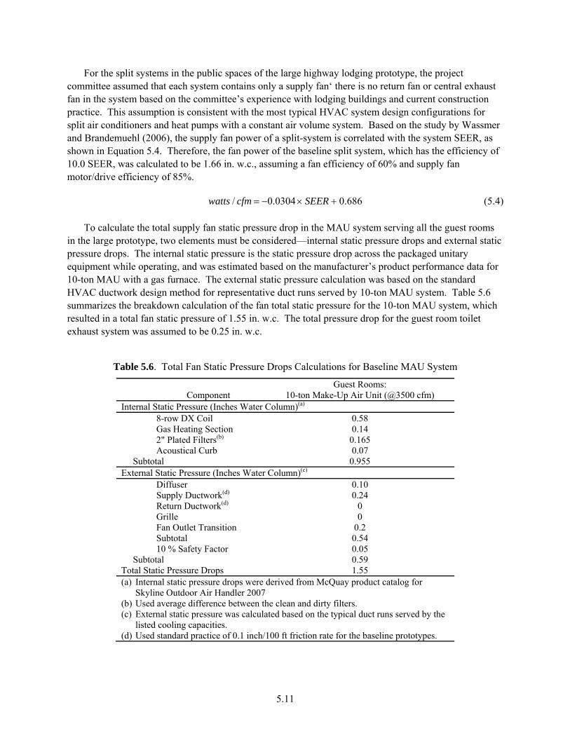
5.11
For the split systems in the public spaces of the large highway lodging prototype, the project committee assumed that each system contains only a supply fan‘ there is no return fan or central exhaust fan in the system based on the committee’s experience with lodging buildings and current construction practice. This assumption is consistent with the most typical HVAC system design configurations for split air conditioners and heat pumps with a constant air volume system. Based on the study by Wassmer and Brandemuehl (2006), the supply fan power of a split-system is correlated with the system SEER, as shown in Equation 5.4. Therefore, the fan power of the baseline split system, which has the efficiency of 10.0 SEER, was calculated to be 1.66 in. w.c., assuming a fan efficiency of 60% and supply fan motor/drive efficiency of 85%.
686.00304.0/ +×−= SEERcfmwatts (5.4)
To calculate the total supply fan static pressure drop in the MAU system serving all the guest rooms in the large prototype, two elements must be considered—internal static pressure drops and external static pressure drops. The internal static pressure is the static pressure drop across the packaged unitary equipment while operating, and was estimated based on the manufacturer’s product performance data for 10-ton MAU with a gas furnace. The external static pressure calculation was based on the standard HVAC ductwork design method for representative duct runs served by 10-ton MAU system. Table 5.6 summarizes the breakdown calculation of the fan total static pressure for the 10-ton MAU system, which resulted in a total fan static pressure of 1.55 in. w.c. The total pressure drop for the guest room toilet exhaust system was assumed to be 0.25 in. w.c.
Table 5.6. Total Fan Static Pressure Drops Calculations for Baseline MAU System
Component Guest Rooms:
10-ton Make-Up Air Unit (@3500 cfm) Internal Static Pressure (Inches Water Column)(a) 8-row DX Coil 0.58 Gas Heating Section 0.14 2" Plated Filters(b) 0.165 Acoustical Curb 0.07 Subtotal 0.955 External Static Pressure (Inches Water Column)(c) Diffuser 0.10 Supply Ductwork(d) 0.24 Return Ductwork(d) 0 Grille 0 Fan Outlet Transition 0.2 Subtotal 0.54 10 % Safety Factor 0.05 Subtotal 0.59 Total Static Pressure Drops 1.55 (a) Internal static pressure drops were derived from McQuay product catalog for
Skyline Outdoor Air Handler 2007 (b) Used average difference between the clean and dirty filters. (c) External static pressure was calculated based on the typical duct runs served by the
listed cooling capacities. (d) Used standard practice of 0.1 inch/100 ft friction rate for the baseline prototypes.

5.12
5.3.6 Ventilation Rates and Schedules
Outdoor air requirement for ventilation was adopted in this Guide to meet the ASHRAE Standard 62-2001. The committee believes that designers are more likely to follow the ventilation rates contained in the Standard 62, and there are no other readily available, credible data sources to support alternative ventilation rates in commercial buildings. The committee chose to use the 2001 version rather than 2004 version to be consistent with the analysis work from the earlier guides. Table 5.7 shows the minimal outside air requirement for each space type in the highway lodging prototypes. It was assumed that outside air was supplied to the guest rooms through MAU system in the large prototype. In the low-end small hotels/motels, represented by the small highway lodging prototype, outside air supply was usually through the vents in the PTAC and PTHP units.
Table 5.7. Minimum Outside Air Requirement by Space Type
Space Type Minimum Outside Air Guest room 30 cfm/room Corridor 0.05 cfm/ft2 Lobby 15 cfm/person Storage 0 cfm/ cfm/ft2 Office 20 cfm/person Laundry 25 cfm/person Meeting room 20 cfm/person Restroom 50 cfm/person Exercise room 20 cfm/person Employee lounge 15 cfm/person Mechanical room 0.05 cfm/ft2
Based on Section 6.2.3.4 of Standard 90.1-1999, motorized damper control is required that will automatically shut when the systems or spaces served are not in use. Therefore, the meeting room in the large prototype, which is usually not in use during night time, was assumed to be equipped with motorized damper. For all the other public spaces and guest rooms, the ventilation air was supplied to the spaces continuously. To simulate the motorized damper control, hourly outdoor ventilation air schedules were modified to follow a two-step control strategy: 1) during the occupied hours, maintain the outdoor air damper at the minimum intake position, or modulate 100% open if the system operates in the economizer mode; 2) during unoccupied (off) hours, automatically close the outdoor air damper to reduce unnecessary outside air intake into the building. This control schedule applied for both the baseline and advanced cases.
5.3.7 Air Economizer
In accordance with Standard 90.1-1999, an economizer is not required if the system size is less than 65,000 Btu/h in cooling capacity, regardless of the climate location. Therefore, the baseline systems have no economizer.
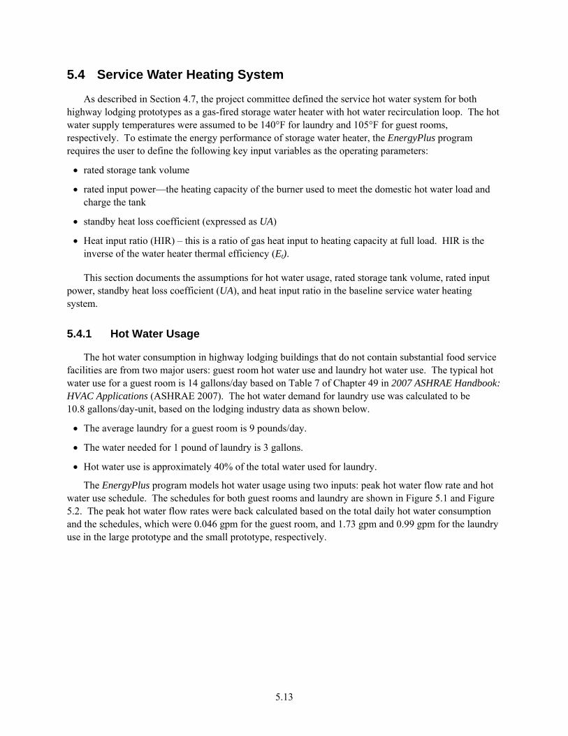
5.13
5.4 Service Water Heating System
As described in Section 4.7, the project committee defined the service hot water system for both highway lodging prototypes as a gas-fired storage water heater with hot water recirculation loop. The hot water supply temperatures were assumed to be 140°F for laundry and 105°F for guest rooms, respectively. To estimate the energy performance of storage water heater, the EnergyPlus program requires the user to define the following key input variables as the operating parameters:
• rated storage tank volume
• rated input power—the heating capacity of the burner used to meet the domestic hot water load and charge the tank
• standby heat loss coefficient (expressed as UA)
• Heat input ratio (HIR) – this is a ratio of gas heat input to heating capacity at full load. HIR is the inverse of the water heater thermal efficiency (Et).
This section documents the assumptions for hot water usage, rated storage tank volume, rated input power, standby heat loss coefficient (UA), and heat input ratio in the baseline service water heating system.
5.4.1 Hot Water Usage
The hot water consumption in highway lodging buildings that do not contain substantial food service facilities are from two major users: guest room hot water use and laundry hot water use. The typical hot water use for a guest room is 14 gallons/day based on Table 7 of Chapter 49 in 2007 ASHRAE Handbook: HVAC Applications (ASHRAE 2007). The hot water demand for laundry use was calculated to be 10.8 gallons/day-unit, based on the lodging industry data as shown below.
• The average laundry for a guest room is 9 pounds/day.
• The water needed for 1 pound of laundry is 3 gallons.
• Hot water use is approximately 40% of the total water used for laundry.
The EnergyPlus program models hot water usage using two inputs: peak hot water flow rate and hot water use schedule. The schedules for both guest rooms and laundry are shown in Figure 5.1 and Figure 5.2. The peak hot water flow rates were back calculated based on the total daily hot water consumption and the schedules, which were 0.046 gpm for the guest room, and 1.73 gpm and 0.99 gpm for the laundry use in the large prototype and the small prototype, respectively.
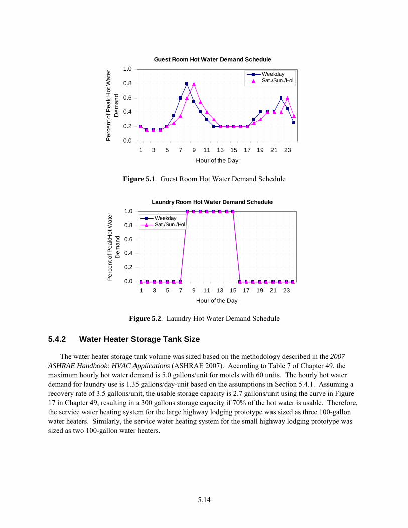
5.14
Guest Room Hot Water Demand Schedule
0.0
0.2
0.4
0.6
0.8
1.0
1 3 5 7 9 11 13 15 17 19 21 23
Hour of the Day
Per
cent
of P
eak
Hot
Wat
er
Dem
and
WeekdaySat./Sun./Hol.
Figure 5.1. Guest Room Hot Water Demand Schedule
Laundry Room Hot Water Demand Schedule
0.0
0.2
0.4
0.6
0.8
1.0
1 3 5 7 9 11 13 15 17 19 21 23
Hour of the Day
Per
cent
of P
eakH
ot W
ater
D
eman
d
WeekdaySat./Sun./Hol.
Figure 5.2. Laundry Hot Water Demand Schedule
5.4.2 Water Heater Storage Tank Size
The water heater storage tank volume was sized based on the methodology described in the 2007 ASHRAE Handbook: HVAC Applications (ASHRAE 2007). According to Table 7 of Chapter 49, the maximum hourly hot water demand is 5.0 gallons/unit for motels with 60 units. The hourly hot water demand for laundry use is 1.35 gallons/day-unit based on the assumptions in Section 5.4.1. Assuming a recovery rate of 3.5 gallons/unit, the usable storage capacity is 2.7 gallons/unit using the curve in Figure 17 in Chapter 49, resulting in a 300 gallons storage capacity if 70% of the hot water is usable. Therefore, the service water heating system for the large highway lodging prototype was sized as three 100-gallon water heaters. Similarly, the service water heating system for the small highway lodging prototype was sized as two 100-gallon water heaters.
5.15
5.4.3 Standby Heat Loss Coefficient and Heat Input Ratio
For the commercial gas storage water heaters, the minimum performance required is expressed as two values, thermal efficiency (Et) and standby heat loss (SL). For a water heater in the size range of 76,000 Btu/hr rated input, the minimum Et was required as 80%. The maximum SL was 1348.8 Btu/hr using following equation required in the ASHRAE Standard 90.1-1999:
V
QSL 110800
+= (5.5)
where SL = standby heat loss (Btu/h) Q = rated input power (Btu/h) V = rated storage tank volume (gallons)
Based on manufacturer’s equipment specifications for commercial water heaters, the most common input rating of a 75-gallon gas storage water heater is 199,000 Btu/h, with recovery efficiency of 80%. Furthermore, the UA of the commercial heater was determined using the following equation:
70
RESLUA ×= (5.6)
where UA = standby heat loss efficient (Btu/hr-°F) SL = standby heat loss (Btu/h) RE = recovery efficiency 70 = difference in temperature between stored water thermostat set point and ambient air
temperature at the test condition (°F)
Plugging in the appropriate values for SL and RE results in a UA of 15.414 Btu/hr-°F, one of input variables for modeling the water heater in the EnergyPlus program.
The HIR is defined by Equation 5.7. The minimum thermal efficiency requirement in the Standard for gas storage water heater with rated input ≥ 76,000 Btu/hr is 80%. This corresponds to a HIR of 1.25, which is one of the inputs for the water heater model in the EnergyPlus program.
tE
HIR 1= (5.7)

6.1
6.0 Development of Advanced Building Model and Assumptions
The project committee began the process of selecting energy savings technologies by reviewing the work done in previous AEDG documents for Small Office, Small Retail, K-12 Schools, Warehouses, and the criteria in ASHRAE Standard 90.1-2007. During the initial energy savings analysis, the project committee decided to use the more-stringent envelope recommendations from the AEDG-SO and AEDG-SR, and use the interior lighting power densities specified in ASHRAE Standard 90.1-2007. By initially using these values, the committee was able to start quickly on the project as the timeline was somewhat compressed and the work on the early rounds of energy savings analysis was greatly facilitated. However, since the highway lodging represents a significantly different building type in terms of its operation and energy use, the committee needed to resort to some exploration of technologies specifically suited to the highway lodging application. The final recommendations included in the Guide were determined based on an iterative process using the project committee’s expertise and the results from modeling the technology recommendations. The following sections describe the process the committee used to choose the technologies for the final recommendations.
The project committee used the below guiding principles to develop the final recommendation for the AEDG-HL.
• Provide recommendations that represent responsible, but not necessarily the best highway lodging design practices. If a recommendation, in general, represents good design practice, it is recommended for all climate zones, even if the resulting savings exceed 30%.
• Use off-the-shelf technologies that are available from multiple sources. The project committee did not recommend technologies or techniques that are one-of-a-kind or available from a single manufacturer.
• Provide recommendations that are at least as stringent as those in ASHRAE 90.1-2007, the most recent version of ASHRAE 90.1. Develop recommendations to address the focus group’s concerns on usability, operation and maintenance (O&M), simplicity, and flexibility.
To quantify the potential energy savings from the recommended energy efficiency measures in the Guide, the advanced building models were simulated by implementing the energy-efficiency technologies noted below. This section contains a topic-by-topic review of advanced building models and how the recommended energy efficiency measures were implemented into the advanced building models. Appendix C summarizes the key simulation parameters for both baseline and advanced cases at each climate location. The energy-efficiency measures include the following:
• enhanced building opaque envelope insulation • high-performance window glazing • reduced lighting power density and occupancy control • high-efficiency appliances and laundry equipment • PTHP and split heat pump application • advanced thermostat control • energy recovery ventilator (ERV) • motorized dampers for outdoor air control during unoccupied hours

6.2
• lower friction rate ductwork design • high-efficiency gas storage water heater • hot water use reduction.
6.1 Envelope
The advanced building prototypes were modeled with the same building form. The Guide recommends the following energy efficiency measures in the envelope section. All the below measures were incorporated into the EnergyPlus models for the advanced building models to estimate the potential energy savings.
• Opaque assemblies – Opaque assemblies, such as roof, walls, floors and doors, were modeled as having the same opaque types and heat capacity as the baseline buildings, but with the enhanced insulation R-values required in the Guide, as described in Section 8.0 of this report.
• Cool roof – Roof exterior finish was recommended by the committee to be a single-ply roof membrane with white EPDM for built-up roofs and metal building roofs in the advanced case. Therefore, the solar reflectance used in the advanced cases for the 43,000 ft² large highway lodging prototype was 0.65, and the corresponding emissivity was 0.86, derived from a study by PG&E (Eilert 2000). The Guide recommends cool roof application only in climate zones 1 through 3. No cool roof is recommended for the attic roofs in this Guide.
• Fenestration – The fenestration in the advanced case was modeled with the same window area as the baseline models. Fenestration U-factor was implemented to meet recommendations for the climate, and the SHGC was set to the maximum allowed for the climate, as shown in Section 8.0 in this report. However, using the window layers method could be problematic in matching the maximum allowable U-factor and SHGC values in accordance with the Guide. The reason is that no windows exist in the EnergyPlus window library, from which the window object could be selected for modeling, to match the fenestration recommendations in the Guide for certain climates. Therefore, a simplified strategy was used to ensure proper estimation of the energy savings potential resulted from the high-performance fenestration. For climate zones 1 through 3, the SHGC value was used as more important criteria for selection because solar radiation significantly contributes to cooling load in warm climate, while for climate zones 6 through 8, U-factor was more important to match with because heat transfer has more impact on heating load change in cold climate.
In addition, the approach to develop the envelope recommendation criteria is documented in Appendix E.
6.2 Internal Loads
6.2.1 Reduced Lighting Power Density and Occupancy Control
Different lighting technologies were used to produce significant energy savings in highway lodging buildings. The recommendations are the same for both prototypes because lighting design requirements and space configuration are similar for the two prototypes.

6.3
6.2.1.1 Interior Lighting
The committee chose to adopt the advanced interior lighting levels that were lower than or the same as those being required by the Standard 90.1-2007. The recommendations for lighting power, 0.74 W/ft2 for guest rooms, 0.9 W/ft2 for offices, 0.5 W/ft2 for corridors, 0.6 W/ft2 for laundry areas, 1.1 W/ft2 for lobby, 0.9 W/ft2 for exercise room, 1.1 W/ft2 for meeting room, and 0.6 W/ft2 for stairs, represent an average lighting power density for these individual spaces, not the entire building. Individual spaces within each space type may have higher power densities if they are offset by lower power densities in other areas within the same space type (breakfast room and elevator lobby would be considered part of the lobby and may be lighted to lower/higher light levels and, therefore, lower/higher LPD allowing higher/lower foot candles and LPD in the main lobby and registration area). The LPD recommendations for the remainder space types are the same as those being required by Standard 90.1-2007.
Table 6.1 summarizes the advanced lighting levels incorporated into the EnergyPlus models for both prototypes. The area-weighted average lighting levels reductions were 62% relative to the 1999 baseline and 25% relative to the 2007 baseline for the large highway lodging prototype, and 69% and 31%, respectively, for the small highway lodging prototype.
Table 6.1. Interior Lighting Power Density by Space Type Comparison
Space Type
LPD (W/ft²) Standard
90.1-1999 Standard
90.1-2004 Standard
90.1-2007 AEDG-HL Guest room 2.5 1.1 1.1 0.74 Corridor 0.7 0.5 0.5 0.5 Lobby 1.8 1.1 1.1 1.1 Stairs 0.9 0.6 0.6 0.6 Office 1.3 1.1 1.1 0.9 Laundry 0.7 0.6 0.6 0.6 Meeting room 1.5 1.3 1.3 1.1 Exercise room 1.1 0.9 0.9 0.9 Storage 1.1 0.8 0.8 0.8 Employee lounge 1.4 1.2 1.2 1.2 Restroom 1.0 0.9 0.9 0.9 Mechanical room 1.3 1.5 1.5 1.5
In addition, occupancy sensor controls for laundry, offices, exercise rooms, meeting rooms, and guest rooms were also recommended by the Guide, and, therefore, included in the simulation for the advanced building models. The impact of occupancy controls was modeled by modifying the peak lighting levels by a percentage to account for typical occupancy densities based on the project committee’s expertise. The lighting operation schedules for advanced buildings are documented in Appendix A. An example is show in Figure 6.1.

6.4
Guest Room Lighting Schedule
0.0
0.2
0.4
0.6
0.8
1.0
1 3 5 7 9 11 13 15 17 19 21 23
Hour of the Day
Per
cent
of P
eak
Ligh
ting
Den
sity
Weekday-BaseSat./Sun./Hol.-BaseWeekday-AdvaSat./Sun./Hol.-Adva
Figure 6.1. Guest Room Interior Lighting Schedules
The committee explored different lighting designs and layouts to achieve low lighting power while maximizing visibility. Based on some lighting modeling studies performed by the committee light expert, it appears that it is possible to fairly easily meet or go below the recommended lighting power density levels contained in the AEDG recommendations. When high-performance lighting technologies, such as compact fluorescent (CFL) with electronic ballast, T5HO or super-T8 with high-performance electronic ballast, combined with occupancy sensors, significant energy savings may be achieved from lighting. Use CFL in down lights, wall sconces, and table lamps. Use incandescent sparingly, such as in accent lighting of artwork or highlighting of special architectural features in the Lobby. These technologies are readily available from major national suppliers, making it easy for designers and builders to find adequate supplies.
No daylighting controls were incorporated into the advanced building modeling for two reasons: 1) no recommendations were provided for daylighting from vertical glazing in the highway lodging buildings; and 2) the studied prototypes, both large and small highway lodging models, do not have skylights.
6.2.1.2 Exterior Lighting
As defined in IESNA RP-33 (IESNA 1999), buildings shall be classified under one of the lighting zones shown in Table 6.2 and shall follow all of the requirements for that specific zone.
Table 6.2. Lighting Zone Descriptions
Lighting Zone Description
1 Developed areas of National Parks, State Parks, Forest Land, and Rural areas 2 Areas predominantly consisting of residential zoning, neighborhood business districts,
light industrial with limited nighttime use and residential mixed use areas 3 All other areas 4 High activity commercial districts in major metropolitan areas as designated by the local
jurisdiction
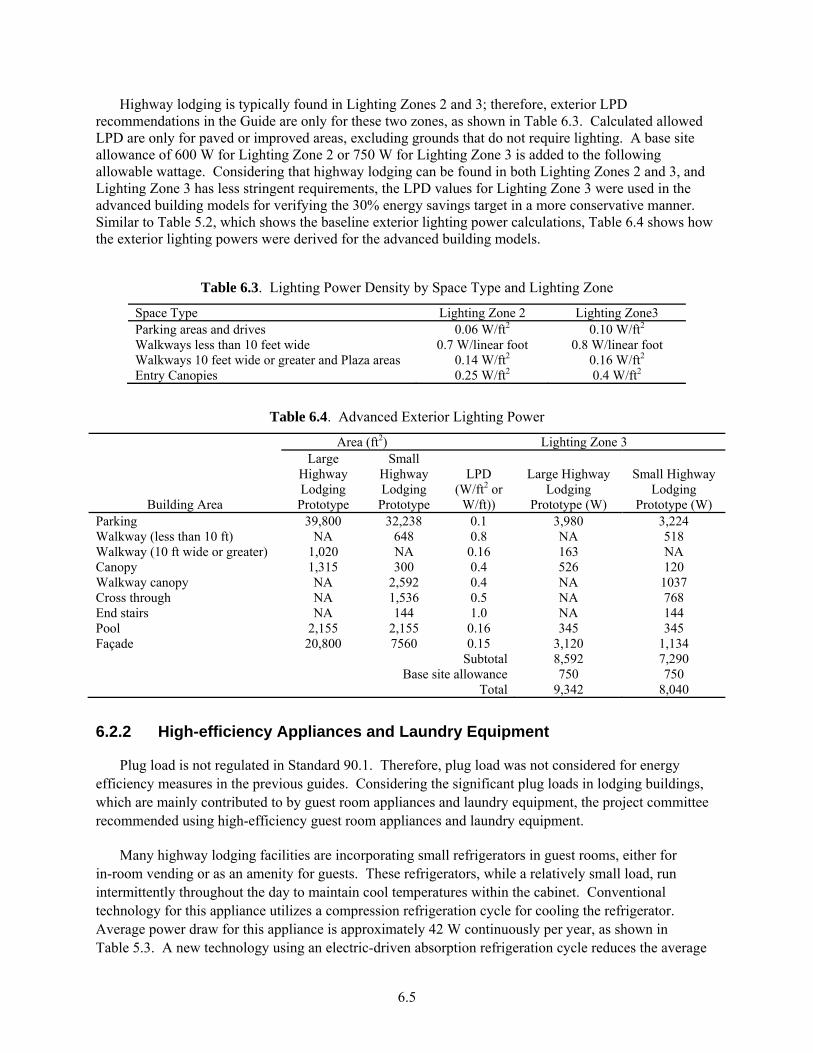
6.5
Highway lodging is typically found in Lighting Zones 2 and 3; therefore, exterior LPD recommendations in the Guide are only for these two zones, as shown in Table 6.3. Calculated allowed LPD are only for paved or improved areas, excluding grounds that do not require lighting. A base site allowance of 600 W for Lighting Zone 2 or 750 W for Lighting Zone 3 is added to the following allowable wattage. Considering that highway lodging can be found in both Lighting Zones 2 and 3, and Lighting Zone 3 has less stringent requirements, the LPD values for Lighting Zone 3 were used in the advanced building models for verifying the 30% energy savings target in a more conservative manner. Similar to Table 5.2, which shows the baseline exterior lighting power calculations, Table 6.4 shows how the exterior lighting powers were derived for the advanced building models.
Table 6.3. Lighting Power Density by Space Type and Lighting Zone
Space Type Lighting Zone 2 Lighting Zone3 Parking areas and drives 0.06 W/ft2 0.10 W/ft2 Walkways less than 10 feet wide 0.7 W/linear foot 0.8 W/linear foot Walkways 10 feet wide or greater and Plaza areas 0.14 W/ft2 0.16 W/ft2 Entry Canopies 0.25 W/ft2 0.4 W/ft2
Table 6.4. Advanced Exterior Lighting Power
Building Area
Area (ft2) Lighting Zone 3 Large
Highway Lodging Prototype
Small Highway Lodging
Prototype
LPD (W/ft2 or
W/ft))
Large Highway Lodging
Prototype (W)
Small Highway Lodging
Prototype (W) Parking 39,800 32,238 0.1 3,980 3,224 Walkway (less than 10 ft) NA 648 0.8 NA 518 Walkway (10 ft wide or greater) 1,020 NA 0.16 163 NA Canopy 1,315 300 0.4 526 120 Walkway canopy NA 2,592 0.4 NA 1037 Cross through NA 1,536 0.5 NA 768 End stairs NA 144 1.0 NA 144 Pool 2,155 2,155 0.16 345 345 Façade 20,800 7560 0.15 3,120 1,134
Subtotal 8,592 7,290 Base site allowance 750 750
Total 9,342 8,040
6.2.2 High-efficiency Appliances and Laundry Equipment
Plug load is not regulated in Standard 90.1. Therefore, plug load was not considered for energy efficiency measures in the previous guides. Considering the significant plug loads in lodging buildings, which are mainly contributed to by guest room appliances and laundry equipment, the project committee recommended using high-efficiency guest room appliances and laundry equipment.
Many highway lodging facilities are incorporating small refrigerators in guest rooms, either for in-room vending or as an amenity for guests. These refrigerators, while a relatively small load, run intermittently throughout the day to maintain cool temperatures within the cabinet. Conventional technology for this appliance utilizes a compression refrigeration cycle for cooling the refrigerator. Average power draw for this appliance is approximately 42 W continuously per year, as shown in Table 5.3. A new technology using an electric-driven absorption refrigeration cycle reduces the average
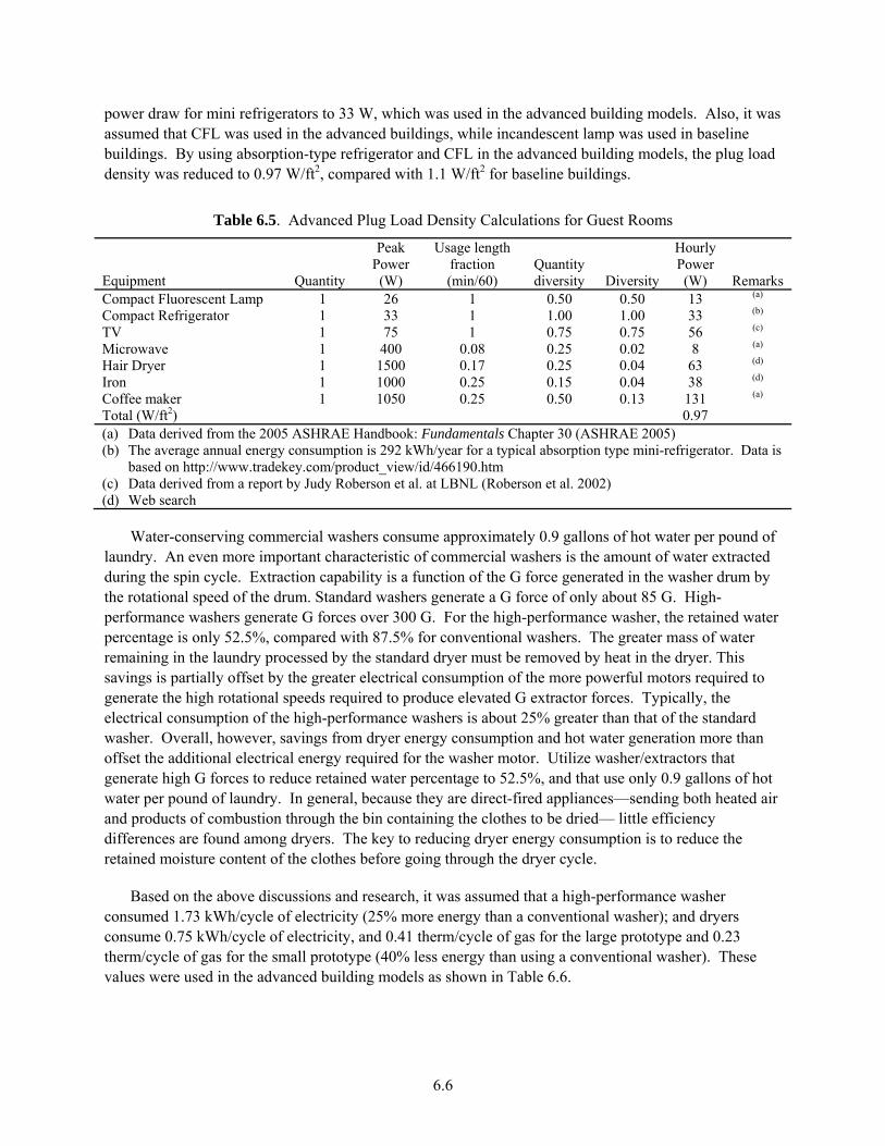
6.6
power draw for mini refrigerators to 33 W, which was used in the advanced building models. Also, it was assumed that CFL was used in the advanced buildings, while incandescent lamp was used in baseline buildings. By using absorption-type refrigerator and CFL in the advanced building models, the plug load density was reduced to 0.97 W/ft2, compared with 1.1 W/ft2 for baseline buildings.
Table 6.5. Advanced Plug Load Density Calculations for Guest Rooms
Equipment Quantity
Peak Power (W)
Usage length fraction (min/60)
Quantity diversity Diversity
Hourly Power (W) Remarks
Compact Fluorescent Lamp 1 26 1 0.50 0.50 13 (a)
Compact Refrigerator 1 33 1 1.00 1.00 33 (b)
TV 1 75 1 0.75 0.75 56 (c)
Microwave 1 400 0.08 0.25 0.02 8 (a)
Hair Dryer 1 1500 0.17 0.25 0.04 63 (d)
Iron 1 1000 0.25 0.15 0.04 38 (d)
Coffee maker 1 1050 0.25 0.50 0.13 131 (a)
Total (W/ft2) 0.97 (a) Data derived from the 2005 ASHRAE Handbook: Fundamentals Chapter 30 (ASHRAE 2005) (b) The average annual energy consumption is 292 kWh/year for a typical absorption type mini-refrigerator. Data is
based on http://www.tradekey.com/product_view/id/466190.htm (c) Data derived from a report by Judy Roberson et al. at LBNL (Roberson et al. 2002) (d) Web search
Water-conserving commercial washers consume approximately 0.9 gallons of hot water per pound of laundry. An even more important characteristic of commercial washers is the amount of water extracted during the spin cycle. Extraction capability is a function of the G force generated in the washer drum by the rotational speed of the drum. Standard washers generate a G force of only about 85 G. High-performance washers generate G forces over 300 G. For the high-performance washer, the retained water percentage is only 52.5%, compared with 87.5% for conventional washers. The greater mass of water remaining in the laundry processed by the standard dryer must be removed by heat in the dryer. This savings is partially offset by the greater electrical consumption of the more powerful motors required to generate the high rotational speeds required to produce elevated G extractor forces. Typically, the electrical consumption of the high-performance washers is about 25% greater than that of the standard washer. Overall, however, savings from dryer energy consumption and hot water generation more than offset the additional electrical energy required for the washer motor. Utilize washer/extractors that generate high G forces to reduce retained water percentage to 52.5%, and that use only 0.9 gallons of hot water per pound of laundry. In general, because they are direct-fired appliances—sending both heated air and products of combustion through the bin containing the clothes to be dried— little efficiency differences are found among dryers. The key to reducing dryer energy consumption is to reduce the retained moisture content of the clothes before going through the dryer cycle.
Based on the above discussions and research, it was assumed that a high-performance washer consumed 1.73 kWh/cycle of electricity (25% more energy than a conventional washer); and dryers consume 0.75 kWh/cycle of electricity, and 0.41 therm/cycle of gas for the large prototype and 0.23 therm/cycle of gas for the small prototype (40% less energy than using a conventional washer). These values were used in the advanced building models as shown in Table 6.6.

6.7
Table 6.6. High-Performance Laundry Equipment Gas Consumption
Washer Type Prototype
Days per
Year No. of Rooms
Laundry Load
(Lbs/room)
% Retained
Water f(G's)
Annual Water
Removed (Lbs)
Btu/lb Water
Total Gas Use
(Therms)
Gas Use (Therms/
cycle) High-
Performance Large 365 77 9 52.5% 132,796 1805 2,397 0.41 Small 44 75,884 1,370 0.23
6.3 HVAC Systems
The recommendations for the HVAC systems in highway lodging buildings followed the same approach as the previous guides with addition of lodging specific technologies, such as PTHP, advanced thermostat control, and energy recovery ventilator. Each of these technologies was demonstrated through simulation to verify the energy savings target in both highway lodging prototypes.
6.3.1 HVAC System Type
The Guide recommended guest room PTAC units incorporating electric heat should use a heat pump cycle as the primary source of room space heating, which are PTHP units. The cooling capacity of the PTHP unit was 9 kBtu/h, which was same as the PTAC in the baseline systems. Based on review of PTHP manufactures’ catalogues, it was assumed that the minimum outside temperature that a PTHP operates in heat pump cycle was 25°F, and resistive defrost control was used. The Guide also recommended using split heat pump systems in the public spaces for the large highway lodging prototype.
Table 6.7. Advanced Buildings HVAC Systems
Prototype Building Area HVAC System Type Large highway lodging prototype Guest rooms PTHP, MAU and exhaust fan
Mechanical room and stairs Unit heaters All other public spaces Split heat pump
Small highway lodging prototype
All spaces
PTHP and exhaust fan
6.3.2 Advanced Thermostat Control
Having a setback temperature for unoccupied periods during the heating season or setup temperature during the cooling season will help to save energy. In guest rooms, limiting conditioning during unoccupied periods can save significant amounts of energy in most climate zones. The Guide recommends installing guest room energy management control systems to manage the guest room air conditioning system for occupied and unoccupied time periods. The guest room thermostat automatically reverts to unoccupied set points (usually 4°F from set point) when the passive infrared (PIR) sensor in conjunction with the door switch determines that the room is indeed unoccupied. Therefore, for rented guest rooms during unoccupied period, typically from 9 am to 4 pm, the thermostat set points were assumed to be 66°F for heating and 74°F for cooling; the same set points were applied to vacant guest rooms.
6.8
Time-of-day scheduling is useful when it is known which portions of the building public space will have reduced occupancy. In the large prototype, setback and setup controls were recommended for the meeting room, which was usually unoccupied during night time. In the advanced building models, the heating set point of 65°F and the cooling set point of 80°F were assumed during night time for the meeting room.
6.3.3 Higher Efficiency HVAC Equipment
For the PTHP equipment, the project committee recommended the minimum cooling efficiency and heating efficiency at certain rated cooling and heating capacities as shown in Equations 6.1 and 6.2. These two efficiency levels were based on DOE’s PTAC/PTHP rulemaking study, which are the Trial Standard Level (TSL) 6 in the notice of proposed rulemaking (PTAC 2008).
)1000/233.0(6.13 CapEER ×−= (6.1)
)1000/053.0(8.3 CapCOP ×−= (6.2)
where Cap is the rated cooling capacity for PTAC and PTHP or the rated heating capacity for PTHP.
The project committee recommended the minimum cooling equipment efficiency of 13.0 SEER and the minimum heating efficiency of 7.7 heating seasonal performance factor (HSPF) for the 5-ton split systems in the public area of the large highway lodging prototype. This recommendation is consistent with the requirements in the previous guides. The required COP input to the EnergyPlus program is derived based on Equation 6.3.
HSPFHSPFCOP ×+×−= 6239.00255.0 2 (6.3)
In addition, the AEDG-HL also continued the recommendations for integrated part load values (IPLV) for commercial cooling equipment because this represents a step forward from the Standard.
6.3.4 Lower Static Pressure Ductwork
To quantify the potential energy savings from the recommended improved ductwork design (low friction rate) in the analysis, the supply fan external static pressure drop for the MAU system in the large highway lodging prototype was re-calculated, based on a maximum ductwork friction rate no greater than 0.08 in. per 100 linear feet of duct run, as recommended by the Guide. In addition, 0.75 in. w.c. of static pressure was added to the supply fans to account for the additional pressure drop over the energy recovery ventilator (ERV) as described in Section 6.3.7. The internal static pressure remained the same as the baseline calculation shown in Table 6.8. The differences compared to the baseline calculation are shaded in Table 6.8, including static pressure drops through diffusers, supply ductwork and ERV. In summary, total fan static pressure of the 10-ton MAU was increased from 1.55 in. w.c. for the baseline system to 2.27 in. w.c for the advanced system due to the additional pressure drop from ERV. The total pressure drop for the split systems in the advanced large prototype models was re-calculated as 1.26 in. w.c. (0.4 in. w.c. reduction from baseline), following the same procedure as described in Section 5.3.3.

6.9
Table 6.8. Total Fan Static Pressure Drops Calculations for the Advanced MAU System
Component Guest Rooms:
10-ton Make-up Air Unit (@3500 cfm) Internal Static Pressure (Inches Water Column)(a) 8-row DX Coil 0.58 Gas Heating Section 0.14 2 in. Plated Filters(b) 0.165 Acoustical Curb 0.07 Subtotal 0.955 External Static Pressure (Inches Water Column)(c) Diffuser 0.05 Supply Ductwork(d) 0.19 ERV 0.75 Return Ductwork(d) 0 Grille 0 Fan Outlet Transition 0.2 Subtotal 0.44 10 % Safety Factor 0.04 Subtotal 0.49 Total Static Pressure Drops 2.27 (a) Internal static pressure drops were derived from McQuay product catalog for Skyline
Outdoor Air Handler 2007 (b) Used average difference between the clean and dirty filters. (c) External static pressure was calculated based on the typical duct runs served by the listed
cooling capacities. (d) Used standard practice of 0.08 inch/100 ft friction rate for the baseline prototypes.
6.3.5 Air Economizer
Following the recommendation in the previous guides, the committee recommended lowering the capacity threshold for air economizers from 65,000 Btu/hr to 54,000 Btu/hr for climate zones 3 through 8. This recommendation applies for single package systems. In the large hotel prototype, the split heat pump systems are assumed to serve the public areas. Thus, the advance large hotel buildings have no economizers implemented.
6.3.6 Energy Recovery Ventilator
Energy recovery ventilator (ERV) can provide an energy-efficient means to deal with the latent and sensible outdoor air cooling loads during peak summer conditions. It can also reduce the required heating of outdoor air in cold climates. In cold climates, make-up air for continuous toilet exhaust from guest rooms with little internal heat gains can require significant energy consumption for space heating. Heat recovery can reduce this heat loss significantly, tempering energy requirements for outdoor air heat.
Exhaust air energy recovery can be provided through a separate ERV that conditions the outdoor air before entering the air-conditioning or heat pump unit, an energy recovery unit that adds on to air-conditioning or heat pump unit, or an air-conditioning or heat pump unit with the integrated energy recovery unit. For lodging guest rooms, heat recovery can be provided between a central toilet exhaust system and a central ventilation air supply system.

6.10
The Guide recommends an exhaust air ERV for the MAU system in the large highway lodging prototype. In the ERV model, it was assumed that the ERV had a sensible effectiveness of 75% and a latent effectiveness of 70% based on manufactures’ catalogues. For the MAU system that was modeled with the ERV, an additional 0.75 in. w.c. of static pressure was added to the supply fans to account for the additional pressure drop over the ERV (shown in Table 6.8), as well as additional 200 W auxiliary power to rotate the energy recovery wheel.
6.4 Service Water Heating
Service water heating constitutes a significant fraction of the total energy usage of highway lodging facilities in all climate zones. Significant energy savings can be achieved by examining each of the components that provide the heated water and control its use. Similar to the previous guides, the SWH recommendations contain technologies for reduction of standby losses by improving energy factors (EF) or by utilizing instantaneous water heaters for fuel-fired applications. When storage water heaters are used, the recommendations result in higher efficiencies for both gas and electric water heaters. Other recommendations unique to the AEDG-HL guide are the hot water usage reduction technologies.
6.4.1 High Efficiency Water Heater
Following the recommendations in the previous guides, this Guide presents two options for gas-fired water heaters as shown in Table 8.3. These are a gas storage water heater with a 90% Et or a gas instantaneous water heater with either a measured 81% Et or a 0.81 energy factor (EF) rating for National Appliance Energy Conservation Act (NAECA) covered water heaters. The Guide also includes the efficiency recommendation for the service water heating system using the electric-resistance water heater. For the electric resistance water heater with capacity no larger than 12 kW, the higher efficiency lever is expressed as the following equation:
VolumeTankStorageRatedEF ×−= 0012.099.0 (6.4)
The studied highway lodging prototypes assumed gas storage water heaters, therefore, the Et of 90% was used in the advanced building models, corresponding to the HIR of 1.11.
6.4.2 Hot Water Usage Reduction
The least expensive means of reducing service water heating energy consumption is by reducing service hot water consumption. Lower flow shower heads can reduce hot water demand during showers from approximately 1.8 gallon per minute (gpm) to less than 1.5 gpm. Lower flow lavatory faucets can produce similar hot water usage reductions for each lavatory. Based on the project committee’s experience, using low flow shower heads and faucets can yield an average of 20% reduction in hot water use compared with the baseline system. This resulted in 11.2 gallons/day-room for guest rooms and 8.1 gallons/day-room for laundry, respectively. These assumptions were used in the advanced building models.
In addition, the Guide recommends using heat recovery for laundry drain water. Potable water supply temperature to the building in winter in cold climates can be extremely low, often below 50°F. Shower drain stack heat recovery units can raise the temperature of cold water supply. Typical shower drain heat

6.11
recovery units are only applicable to multi-story buildings or buildings with basements, because they require a full story of vertical drop for the integral shower drain stack heat exchanger. For hotel laundries, heat recovery units recover heat, either to the cold water supply to the washer or to the make-up water to the water heater. Either approach can significantly reduce water heating energy consumption in cold climates.
An on-the-market device that utilizes this technology is the Gravity-Film-Heat Exchanger (GFX) device developed by WaterFilm Energy, Inc.1 The device is installed vertically in the plumbing system. As waste hot water flows down through the vertical pipe wrapped with GFX copper tubing, the waste water's heat energy is transferred through the copper pipe and tubing to the incoming cold water. There is no pump and no storage tank needed for the device, and it uses no electricity, so there is no operating cost. The GFX is most closely approximated with the counterflow heat exchanger. The EnergyPlus program requires inputting heat transfer coefficient (UA value) of GFX. As shown in Table 6.9, the UA was calculated using Logarithmic Mean Temperature Difference (LMTD) method based on the published performance data for a GXF device used for laundry drain water (model PS4-60)2.
Table 6.9. Gravity-Film-Heat-Exchanger Model PS4-60 Performance
Model Water Flow Rate
(GPM)(a) EWTc (°F )
LWTc (°F )
EWTh (°F )
LWTh (°F )
Q (Btu/hr)
LMTD (°F )
UA (Btu/hr-°F )
PS4-60 10 60 77.5 95 79.5 77,548 18.482 4196 (a) 10 GPM cold and 10 GPM pit water at 95F avg. temperature EWTc = cold water entering temperature, °F LWTc = cold water leaving temperature, °F EWTh = drain waste water entering temperature, °F LWTh = drain waster water leaving temperature, °F
LMTDUAQ ×=
)]/()ln[()]()[(
chch
chch
EWTLWTLWTEWTEWTLWTLWTEWT
LMTD−−−−−
=
1 http://gfxtechnology.com 2 The performance data can obtained from: http://gfxtechnology.com/T-C.pdf

7.1
7.0 Development of Cost Effectiveness Data
The charge given to the AEDG-HL Project Committee clearly delineated that the objective function of the work was to maximize energy savings. Cost effectiveness was not specified as one of the key variables to consider by the Steering Committee. The Steering Committee’s concern about asking the committee to consider cost effectiveness was the potential effort necessary to collect large amounts of cost data on various measures as well as the challenges in establishing agreement on parameters such as measure life, installation costs and the economic parameters such as discount rates and fuel escalation rates. For these reasons the guides themselves have not contained information on cost effectiveness. This was deemed acceptable by the Steering Committee since the guides are voluntary recommendations rather than mandatory requirements like those contained in building codes and standards.
Based on feedback received from DOE, as well as users and promoters of the guides, there is a strong interest in having some sense of the additional costs necessary to meet the recommended energy performance levels in the guides. Most of the input was focused on the need to have a sense for the additional construction costs rather than the actual cost effectiveness. The cost data provided in this report is intended to represent a reasonable estimate of the incremental costs for an energy efficient hotel representative of the highway lodging category based on the large prototype hotel (43,000 ft2) used for performing energy simulations. This analysis uses incremental costs as the basis of comparison to help offset some of the biases in cost data when the cost data is deemed to be either routinely high or routinely low. For example, cost data from R.S. Means is generally considered to be a bit high in absolute value by consulting engineers who frequently use R.S. Means data as a method of quick estimation for budgeting purposes. On the other side, the cost data from a major hotel chain might be low in absolute value due to the volume buying power of the hotel chain. Using differences between the baseline and the advanced energy features costs (i.e., incremental costs), whether absolutely high or low, may result in costs which are more representative of the actual incremental cost seen in the industry.
7.1 Basis for Incremental Energy Savings Measure Costs
The costs for various energy savings measures are developed as incremental costs based on the difference between the costs for the baseline measure and the costs for the energy savings measure. The incremental costs may be based on a per unit cost, such as costs per square foot of wall area, or a per building cost, such as the cost of a single air conditioning unit that serves an entire building or section of a building. This approach requires that for each measure both the baseline cost and the energy savings measure cost must be developed or data must be explicitly available on incremental costs.
The 43,000-ft² hotel prototype building described in Section 4.0 was used as the basis to develop the cost data. Costs were developed for each of the efficiency measures used in the building, and then the measure costs will be summed to get the overall cost premium for the building prototype. Table 7.1 summarizes the basis for estimating both the baseline and energy savings costs for each of the critical measures for the prototype building. The results are shown in Table 7.2.

7.2
Table 7.1. Baseline and Energy Saving Costs Summary for the 43,000-ft² Hotel
Component Cost Equation Source Roof insulation Cost = Area of roof x incremental cost/ft2 of higher
insulation value SSPC 90.1 Cost Database
Cool roof Cost = Area of roof x incremental cost/ft2 of cool roof treatment
Cool Roof Database
Exterior wall insulation Cost = Net area of exterior wall x incremental cost/ft2 of higher insulation value
SSPC 90.1 Cost Database
Slab-on-grade insulation Cost = Perimeter of slab x incremental cost/ft of higher insulation value
SSPC 90.1 Cost Database
Fenestration – Windows & doors
Cost = Area of windows x incremental cost /ft2 of window type
SSPC 90.1 Cost Database
Interior lighting – LPD Cost = Incremental cost of bulbs x number of bulbs used
Grainger catalog
Cost = Incremental cost of ballasts x number of ballasts used
Grainger catalog
Exterior Lighting Cost=Incremental savings based on reduction in fixtures
Seattle Lighting Laboratory
Occupancy sensors Cost = Additional costs of occupancy sensors Estimates provided by Seattle Lighting Laboratory
Cooling – Air conditioner efficiency
Cost = Incremental cost/ton for higher EER x total tonnage Cost= Incremental cost for heat pumps
DOE Technical Support Document for PTAC/PTHP Rulemaking, A. Davis Langdon Study
Guest room vacancy sensors
Cost = Installed costs of PIR sensor, door switch, HVAC relay and DDC programming
Contractor quotation
Low flow guest bathroom fixtures
Cost = Incremental costs of low flow shower heads and faucets
McMaster-Carr Supply catalog and Grainger catalog
Laundry – Washer Cost = Incremental cost of higher extraction rate washer
Continental MSRP
Laundry-Heat Recovery Cost = Incremental cost of installing drain water recovery system
Hilton Corporation estimates
Ventilation – Makeup Air Unit
Cost = Incremental cost/ton for higher EER x total tonnage
A Davis Langdon Study
Ventilation – ERV Wheel
Cost = Additional cost of ERV wheel R.S. Means
Plug Loads Cost = Incremental cost of refrigerator Industrial quotations, Hampton Inn quotations
Pipe and Duct Insulation
Cost = Additional cost of insulation material Industrial quotations
Service Water Heating Cost = Additional cost of higher efficiency water heater
Pacific Gas and Electric estimate

7.3
Table 7.2. Incremental Costs per Building for Energy Measures in 43,000 ft² Hotel
Item Component Zone 1 Zone 2 Zone 3 Zone 4 Zone 5 Zone 6 Zone 7 Zone 8 Opaque Elements Roof Insulation $4,104.00 $4,104.00 $4,104.00 $4,104.00 $4,104.00 $4,104.00 $8,100.00 $7,992.00
Exterior Wall Insulation $12,724.80 $17,284.80 $9,345.60 $10,507.20 $6,336.00 $5,174.40 $5,174.40 $22,502.40 Slab Insulation $0.00 $0.00 $0.00 $1,608.00 $1,608.00 $244.80 $244.80 $201.60 Cool Roof $7,884.00 $7,884.00 $7,884.00 $7,884.00 $7,884.00 $7,884.00 $0.00 $0.00
Fenestration Windows & doors $10,639.60 $15,224.95 $11,910.00 $2,520.95 $2,520.95 $2,520.95 $2,024.70 $25,606.50 Interior Lighting Lighting $3,358.31
Occupancy Sensors $4,077.07 Exterior Lighting Parking lot, canopy, facade ($3,900.00) Cooling/Heating Heat Pump Efficiency $18,297.00
Vacancy sensors in guest rooms
$32,648.00
Laundry Extractor Washer $4,400.00 Drain Water Heat Recovery $8,500.00
Ventilation Makeup Air Unit $2,560.00 Energy Recovery Ventilator $8,849.40
Ducts Insulation $864.60 Pipes Insulation $1,444.00 Low flow fixtures Shower head and faucet ($3,856.93) Plug Loads Refrigerator $13,013.00 SWH Efficiency factor $4,000.00 TOTAL $129,606.85 $138,752.20 $127,498.05 $120,878.60 $116,707.40 $114,182.60 $109,798.35 $150,556.95
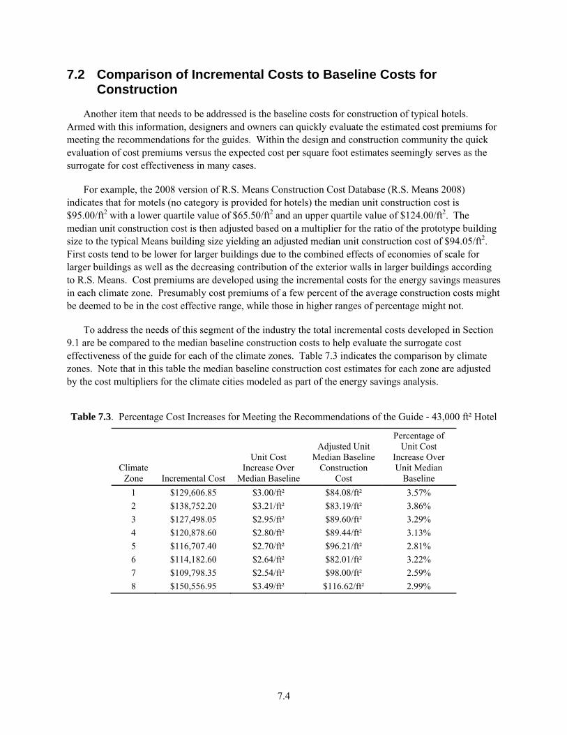
7.4
7.2 Comparison of Incremental Costs to Baseline Costs for Construction
Another item that needs to be addressed is the baseline costs for construction of typical hotels. Armed with this information, designers and owners can quickly evaluate the estimated cost premiums for meeting the recommendations for the guides. Within the design and construction community the quick evaluation of cost premiums versus the expected cost per square foot estimates seemingly serves as the surrogate for cost effectiveness in many cases.
For example, the 2008 version of R.S. Means Construction Cost Database (R.S. Means 2008) indicates that for motels (no category is provided for hotels) the median unit construction cost is $95.00/ft2 with a lower quartile value of $65.50/ft2 and an upper quartile value of $124.00/ft2. The median unit construction cost is then adjusted based on a multiplier for the ratio of the prototype building size to the typical Means building size yielding an adjusted median unit construction cost of $94.05/ft2. First costs tend to be lower for larger buildings due to the combined effects of economies of scale for larger buildings as well as the decreasing contribution of the exterior walls in larger buildings according to R.S. Means. Cost premiums are developed using the incremental costs for the energy savings measures in each climate zone. Presumably cost premiums of a few percent of the average construction costs might be deemed to be in the cost effective range, while those in higher ranges of percentage might not.
To address the needs of this segment of the industry the total incremental costs developed in Section 9.1 are be compared to the median baseline construction costs to help evaluate the surrogate cost effectiveness of the guide for each of the climate zones. Table 7.3 indicates the comparison by climate zones. Note that in this table the median baseline construction cost estimates for each zone are adjusted by the cost multipliers for the climate cities modeled as part of the energy savings analysis.
Table 7.3. Percentage Cost Increases for Meeting the Recommendations of the Guide - 43,000 ft² Hotel
Climate Zone Incremental Cost
Unit Cost Increase Over
Median Baseline
Adjusted Unit Median Baseline
Construction Cost
Percentage of Unit Cost
Increase Over Unit Median
Baseline 1 $129,606.85 $3.00/ft² $84.08/ft² 3.57% 2 $138,752.20 $3.21/ft² $83.19/ft² 3.86% 3 $127,498.05 $2.95/ft² $89.60/ft² 3.29% 4 $120,878.60 $2.80/ft² $89.44/ft² 3.13% 5 $116,707.40 $2.70/ft² $96.21/ft² 2.81% 6 $114,182.60 $2.64/ft² $82.01/ft² 3.22% 7 $109,798.35 $2.54/ft² $98.00/ft² 2.59% 8 $150,556.95 $3.49/ft² $116.62/ft² 2.99%
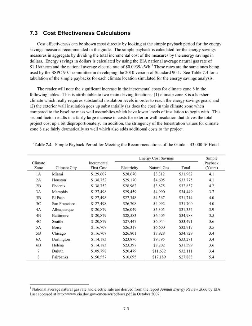
7.5
7.3 Cost Effectiveness Calculations
Cost effectiveness can be shown most directly by looking at the simple payback period for the energy savings measures recommended in the guide. The simple payback is calculated for the energy savings measures in aggregate by dividing the total incremental cost of the measures by the energy savings in dollars. Energy savings in dollars is calculated by using the EIA national average natural gas rate of $1.16/therm and the national average electric rate of $0.0939/kWh.1 These rates are the same ones being used by the SSPC 90.1 committee in developing the 2010 version of Standard 90.1. See Table 7.4 for a tabulation of the simple paybacks for each climate location simulated for the energy savings analysis.
The reader will note the significant increase in the incremental costs for climate zone 8 in the following tables. This is attributable to two main driving functions: (1) climate zone 8 is a harsher climate which really requires substantial insulation levels in order to reach the energy savings goals, and (2) the exterior wall insulation goes up substantially (as does the cost) in this climate zone when compared to the baseline mass wall assemblies which have lower levels of insulation to begin with. This second factor results in a fairly large increase in costs for exterior wall insulation that drives the total project cost up a bit disproportionately. In addition, the stringency of the fenestration values for climate zone 8 rise fairly dramatically as well which also adds additional costs to the project.
Table 7.4. Simple Payback Period for Meeting the Recommendations of the Guide – 43,000 ft² Hotel
Climate Zone Climate City
Incremental First Cost
Energy Cost Savings Simple Payback (Years) Electricity Natural Gas Total
1A Miami $129,607 $28,670 $3,312 $31,982 4.1 2A Houston $138,752 $29,170 $4,605 $33,775 4.1 2B Phoenix $138,752 $28,962 $3,875 $32,837 4.2 3A Memphis $127,498 $29,459 $4,990 $34,449 3.7 3B El Paso $127,498 $27,348 $4,367 $31,714 4.0 3C San Francisco $127,498 $26,708 $4,992 $31,700 4.0 4A Albuquerque $120,879 $26,049 $5,305 $31,354 3.9 4B Baltimore $120,879 $28,583 $6,405 $34,988 3.5 4C Seattle $120,879 $27,447 $6,044 $33,491 3.6 5A Boise $116,707 $26,317 $6,600 $32,917 3.5 5B Chicago $116,707 $26,801 $7,928 $34,729 3.4 6A Burlington $114,183 $23,876 $9,395 $33,271 3.4 6B Helena $114,183 $23,397 $8,202 $31,599 3.6 7 Duluth $109,798 $20,479 $11,632 $32,111 3.4 8 Fairbanks $150,557 $10,695 $17,189 $27,883 5.4
1 National average natural gas rate and electric rate are derived from the report Annual Energy Review 2006 by EIA. Last accessed at http://www.eia.doe.gov/emeu/aer/pdf/aer.pdf in October 2007.

7.6
7.4 A Perspective on Costs for Advanced Buildings
With the growth of activity in the high performance buildings market there is a commensurate growth in the desire to understand the real costs to achieve these higher levels of energy performance in buildings. Any effort such as the one included in this document is inevitably faced with the challenges of finding good, credible sources of cost data, particularly when some of the more advanced measures are being considered. The reader will note that the sources for this work run the gamut of widely published data such as might be found in R. S. Means or Grainger as well as sources such as the SSPC 90.1 Cost Database or data found on websites and in testimonials. Clearly it would be desirable to have robust costs for all measures, collected in a consistent manner. Unfortunately this situation does not exist, and it is for this reason that even a fairly simple exercise such as the one in the document becomes fairly difficult to execute.
Many choices had to be made in choosing sources of cost data for this study which involved considering the basis for the data as well as agonizing over whether the source was biased high or low relative to other costs. Generally the authors understand that some sources are routinely high or low and this impact can usually be mitigated by using the differential costs as noted earlier in this section of the report. Sometimes the actual range of cost estimates is so broad that the authors had to struggle to make a reasonable guess as to which costs to use. When confronted with conflicting or ambiguous costs the general approach followed was to take the conservative view of not underestimating the costs such that the exercise would yield an inflated assessment of the cost effective nature of the measures. Conversely, every effort was made to not unduly burden the analysis with costs which were systematically too high, thus biasing the results against undertaking these advanced energy design projects.
An additional challenge was encountered in developing baseline costs for measures which may not be on the market at the present time. For example, compact fluorescent bulbs with electronic ballasts dominate the market and are actually cheaper today than those with magnetic ballasts. Bathroom fixtures designed for low water flow dominate the market and older sources had to be used to estimate the costs of the higher flow fixtures. In both of these cases older data sources and catalogs were reviewed to find equivalent bulbs and fixtures for which prices were available. These prices were then escalated using the R.S. Means cost index for the year the data was available and escalating the cost to current dollars. In some cases, such as the case of the low flow fixtures, this resulted in cost savings as the baseline fixtures actually cost more than the low flow fixtures in current dollars.

8.1
8.0 Final Recommendations and Energy Savings Results
This section contains the final recommendations approved by the project committee for the AEDG-HL, as well as the energy savings results that are achieved as a result of applying these recommendations to the prototypical buildings. The recommendations are applicable for all highway lodging buildings within the scope of the Guide as a means of demonstrating the 30% energy savings. The Guide recognizes that there are other ways of achieving the 30% energy savings, and offers these recommendations as “a way, but not the only way” of meeting the energy savings target. When a recommendation contains the designation “NR”, then the Guide is providing no recommendation for this component or system. In these cases, the requirements of Standard 90.1-1999 or the local code (whichever is more stringent) will apply.
8.1 Final Energy Savings Recommendations
This section describes the final energy savings recommendations in the AEDG-HL. The recommendations are grouped into envelope measures, lighting measures, HVAC measures, SWH measures, and miscellaneous appliances measures.
8.1.1 Envelope Measures
The envelope measures cover the range of assemblies for both the opaque and fenestration portions of the buildings. Opaque elements include the roof, walls, floors and slabs, as well as opaque doors. Fenestration covers the vertical glazing (including doors). For each building element, there are a number of components for which the Guide provides recommendations. In some cases, these components represent an assembly, such as an attic or a steel-framed wall, and in other cases, the components may relate to the allowable area, such as the window-to-wall ratio of the buildings.
Recommendations for each envelope component are contained in Table 8.1, and are organized by climate zone, ranging from the hot Zone 1 to the cold Zone 8. Consistent with the movement from the hotter to colder zones, the insulation requirements (R-value) increase as the climates get colder, and corresponding thermal transmittance (U-factor) decreases. Control of solar loads is more important in the hotter, sunnier climates, and thus the solar heat gain coefficient tends to be more stringent (lower) in Zone 1 and higher in Zone 8. The reader should note that the AEDG-HL does not include any recommendations for the metal buildings because lodging buildings do not usually have this type of construction, based on experience of those in the construction industry.
In several additional cases, the recommendations, such as the window-to-wall ratio, are constant across all climate zones, which suggest insensitivity to climate. These areas are limited to reduce overall energy use regardless of the climate. In addition, the Guide recommends using exterior sun control on the south, east and west orientations of glazing to help control unnecessary solar loads in warmer climates.

8.2
Table 8.1. Final Energy Savings Recommendations for Highway Lodging – Building Envelope
Item Component Zone 1 Zone 2 Zone 3 Zone 4 Zone 5 Zone 6 Zone 7 Zone 8
Roof
Insulation entirely above deck
R-20 ci R-20.0 ci R-20.0 ci R-20.0 ci R-20.0 ci R-20.0 ci R-25.0 ci R-30.0 ci
Attic and other R-38.0 R-38.0 R-38.0 R-38.0 R-38.0 R-38.0 R-60.0 R-60.0
Single rafter R-38.0 R-38.0 R-38.0 R-5.0 ci
R-38.0 R-5.0 ci
R-38.0 + R-5.0 ci
R-38.0 + R-5.0 ci
R-38.0 + R-10.0 ci
R-38.0 + R-10.0 ci
Solar reflectance index
78 78 78 NR NR NR NR NR
Walls-Exterior
Mass (HC > 7 Btu/ft2)
R-5.7 ci R-7.6 ci R-11.4 ci R-13.3 ci R-13.3 ci R-13.3 ci R-15.2 ci R-25.0 ci
Steel framed R-13.0 R-13.0+ R-7.5 ci
R-13.0+ R-7.5 ci
R-13.0+ R-7.5 ci
R-13.0+ R-7.5 ci
R-13.0+ R-7.5 ci
R-13.0+ R-15.6 ci
R-13.0+ R-21.6 ci
Wood framed and other R-13.0 R-13.0 R-13.0 R-13.0+
R-3.8 ci R-13.0+ R-7.5 ci
R-13.0+ R-7.5 ci
R-13.0+ R-10.0 ci
R-13.0+ R-15.6 ci
Slabs Unheated NR NR NR R-10.0 for 24 in.
R-10.0 for 24 in.
R-15.0 for 24 in.
R-15.0 for 24 in.
R-20.0 for 24 in.
Doors Opaque
Swinging U-0.70 U-0.70 U-0.70 U-0.50 U-0.50 U-0.50 U-0.50 U-0.50 Non-Swing U-1.45 U-0.50 U-0.50 U-0.50 U-0.50 U-0.50 U-0.50 U-0.50
Vertical glazing (Including doors)
Area (percent of gross wall) 25% 25% 25% 25% 25% 25% 25% 25%
Thermal transmittance U-0.56 U-0.45 U-0.41 U-0.38 U-0.35 U-0.35 U-0.33 U-0.25
Solar heat gain coefficient (SHGC)
N,S,E,W-0.25
N,S,E,W-0.25
N,S,E,W-0.25
N,S,E,W-0.40
N,S,E,W-0.40
N,S,E,W-0.40
N,S,E,W-0.41
N,S,E,W-0.38
Exterior sun control (S, E, W only)
PF>0.5 PF>0.5 PF>0.5 PF>0.5 PF>0.5 PF>0.5 PF>0.5 PF>0.5
8.1.2 Lighting Measures
The lighting measures are not climate dependent. As such, the same recommendations are provided for all climate zones. Recommendations are provided for interior lighting (including additional light power allowances and occupancy control), as well as exterior lighting, as shown in Table 8.2.
Interior lighting recommendations include maximum lighting power densities (LPD)s requirements for the major space types in highway lodging buildings. Additional recommendations cover the minimum performance of the light sources and ballasts (minimum mean lumens/watt). Occupancy control recommendations are also provided.
Exterior lighting recommendations include maximum LPD requirements for exterior lighting applications in two lighting zones where highway lodging buildings are most likely located.
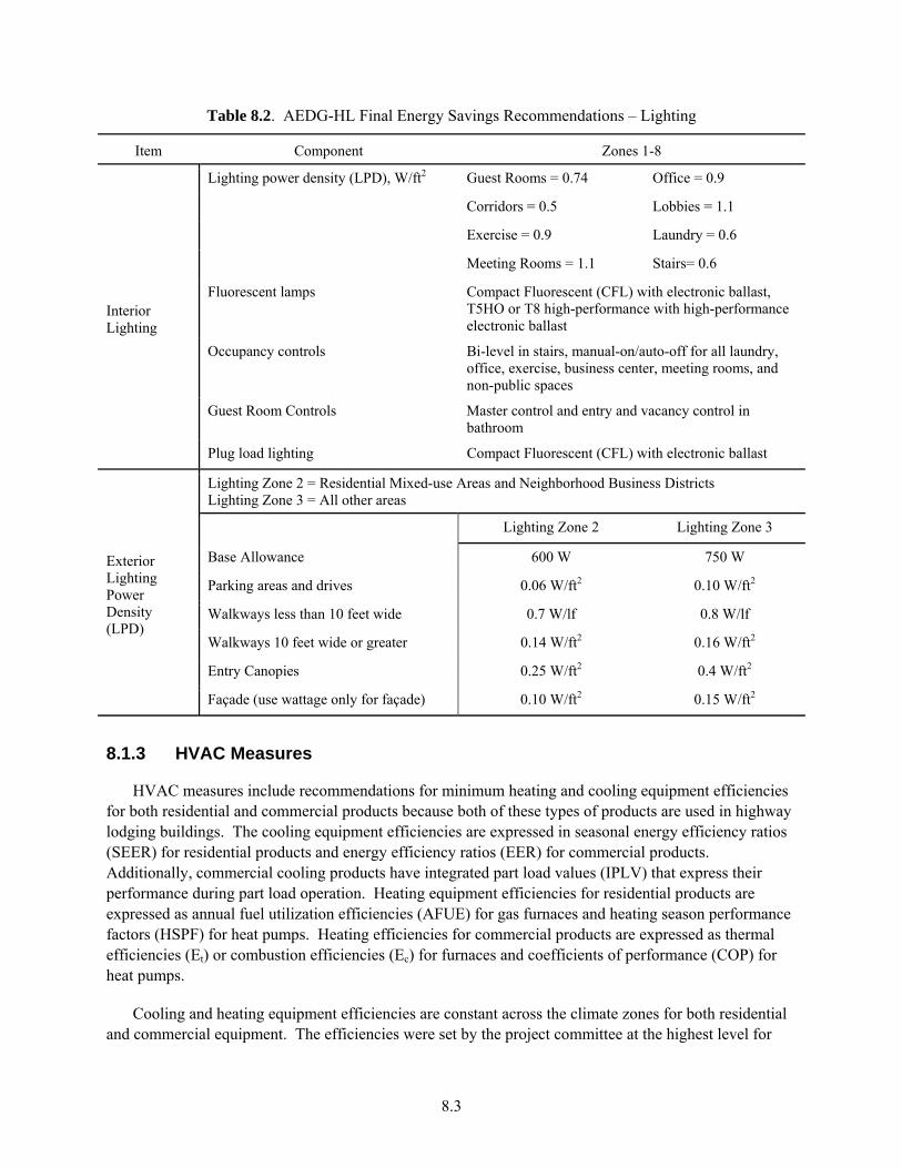
8.3
Table 8.2. AEDG-HL Final Energy Savings Recommendations – Lighting
Item Component Zones 1-8
Interior Lighting
Lighting power density (LPD), W/ft2 Guest Rooms = 0.74 Office = 0.9
Corridors = 0.5 Lobbies = 1.1
Exercise = 0.9 Laundry = 0.6
Meeting Rooms = 1.1 Stairs= 0.6
Fluorescent lamps Compact Fluorescent (CFL) with electronic ballast, T5HO or T8 high-performance with high-performance electronic ballast
Occupancy controls Bi-level in stairs, manual-on/auto-off for all laundry, office, exercise, business center, meeting rooms, and non-public spaces
Guest Room Controls Master control and entry and vacancy control in bathroom
Plug load lighting Compact Fluorescent (CFL) with electronic ballast
Exterior Lighting Power Density (LPD)
Lighting Zone 2 = Residential Mixed-use Areas and Neighborhood Business Districts Lighting Zone 3 = All other areas
Lighting Zone 2 Lighting Zone 3
Base Allowance 600 W 750 W
Parking areas and drives 0.06 W/ft2 0.10 W/ft2
Walkways less than 10 feet wide 0.7 W/lf 0.8 W/lf
Walkways 10 feet wide or greater 0.14 W/ft2 0.16 W/ft2
Entry Canopies 0.25 W/ft2 0.4 W/ft2
Façade (use wattage only for façade) 0.10 W/ft2 0.15 W/ft2
8.1.3 HVAC Measures
HVAC measures include recommendations for minimum heating and cooling equipment efficiencies for both residential and commercial products because both of these types of products are used in highway lodging buildings. The cooling equipment efficiencies are expressed in seasonal energy efficiency ratios (SEER) for residential products and energy efficiency ratios (EER) for commercial products. Additionally, commercial cooling products have integrated part load values (IPLV) that express their performance during part load operation. Heating equipment efficiencies for residential products are expressed as annual fuel utilization efficiencies (AFUE) for gas furnaces and heating season performance factors (HSPF) for heat pumps. Heating efficiencies for commercial products are expressed as thermal efficiencies (Et) or combustion efficiencies (Ec) for furnaces and coefficients of performance (COP) for heat pumps.
Cooling and heating equipment efficiencies are constant across the climate zones for both residential and commercial equipment. The efficiencies were set by the project committee at the highest level for

8.4
which there were available products from multiple manufacturers. For the residential packaged unitary products, these levels have been adopted by federal law as the minimum mandatory manufacturing standards. For package terminal heat pumps (PTHP), the efficiency level was set at the highest level for which there were available products from multiple manufacturers, based on DOE’s current PTAC/PTHP rulemaking analysis.
HVAC measures also include system recommendations, such as lowering the capacity threshold for economizers to 54,000 Btu/h for Zone 3 through 8, using motorized dampers to control the introduction of outdoor air during off hours and energy recovery ventilator (ERV), and recommendations for the design, sealing, and location of ductwork. As shown in Table 8.3, all the recommendations for HVAC are not climate dependent except for the recommendations for economizer.
Table 8.3. AEDG-HL Final Energy Savings Recommendations – HVAC
Item Component Zones 1-8 (except economizer)
HVAC Heating System (Guest Rooms) Primary heat source electric heat pump cycle or gas-fired furnace or boiler
Air conditioner (0-65 kBtu/h) 13.0 SEER Air conditioner (>65-135 kBtu/h ) 11.3 EER/11.5 IPLV Air conditioner (>135-240 kBtu/h ) 11.0 EER/11.5 IPLV Air conditioner (>240 kBtu/h) 10.6 EER/11.2 IPLV Gas furnace (0-225 kBtu/h - SP) 80% AFUE or Et Gas furnace (0-225 kBtu/h - Split) 80% AFUE or Et Gas furnace (>225 kBtu/h ) 80% Ec Packaged Terminal Heat Pump (all capacities)
EER = 13.6 – (0.233 x Cap/1000) COP = 3.8 – (0.053 x Cap/1000)
Air Source Heat pump (0-65 kBtu/h) 13.0 SEER/7.7 HSPF Air Source Heat pump (>65-135 kBtu/h) 10.6 EER/11.0 IPLV/3.2 Htg COP Air Source Heat pump (>135 kBtu/h) 10.1 EER/11.5 IPLV/3.1 Htg COP Hydronic Heat pump (0-18 kBtu/h) 14.6 EER, 4.6 Htg COP. Hydronic Heat pump (>19 kBtu/h) 15.0 EER, 4.8 Htg COP Hydronic Heat Pump Heat Source Use condensing boiler for circulating loop heat source Pumping for Water Source Heat Pumps Variable speed pumping; water treatment Hydronic Heat Pump Heat Rejection Control cooling tower to maximize heat pump EER
Economizer Air conditioners & heat pumps – Single Package
Zone 1and 2: NR Zone 3 to 8: Cooling capacity > 54 kBtu/h
Ventilation Ventilation Air Supply Control ventilation supply volume to match occupancy Heat Recovery Ventilation heat recovery with toilet exhaust
Ducts Friction rate 0.08 in. w.c./100 feet Sealing Seal class B Location Interior only Insulation level R-6
8.1.4 Service Water Heating Measures
SWH measures include recommendations for the use of instantaneous water heaters for fuel-fired applications and enhanced efficiencies for storage applications. Recommendations are also provided for enhanced pipe insulation. Different from the other guides, AEDG-HL also recommends using water conserving equipment and laundry drain water recovery, which are specific to lodging building applications. Table 8.4 summarizes the recommendations for the SWH measures.

8.5
Table 8.4. AEDG-HL Final Energy Savings Recommendations – Service Water Heating
Item Component Zones 1-8
Service Water Heating
Gas water heater efficiency Storage - 90% Et, Instantaneous - 0.81 EF or 81% Et; Electric storage EF (≤12 kW , ≥20 gal) EF > 0.99 – 0.0012xVolume
Hot water usage reduction
Use 1.75 gpm shower heads, 1.0 gpm faucets and water conserving clothes washers. Utilize laundry heat recovery
Water heater sizing/ location
Avoid oversizing and excessive supply temperatures
Pipe insulation (d<1½ in./ d≥1½ in.) 1 in./ 1½ in.
8.1.5 Miscellaneous Appliances Measures
One of the unique features of the AEDG-HL Guide is that it provides recommendations for plug loads, as summarized in Table 8.5, considering that plug loads consume significant energy in lodging buildings. The Guide recommends using an absorption type of refrigerator and a high-efficiency washer.
Table 8.5. AEDG-HL Final Energy Savings Recommendations –Miscellaneous Appliances
Item Component Zones 1-8 Miscellaneous Appliances
Guest Room Mini-Refrigerator Absorption Refrigeration Cycle 33W continuously High Efficiency Laundry Equipment
0.9 gal water / lb laundry 354G Extractor with Retained water < 52.5%
8.2 Energy Savings Results
Once the project committee determined the final recommendations, the prototype large and small lodgings were simulated in each of the 15 climate locations to determine if the 30% energy savings goal was achieved. The whole building energy savings results for the recommendations are summarized in Table 8.6 for both the small HL and the large HL prototypes. In addition, the energy savings in percentage are also provided in Figure 8.1 for the small HL and in Figure 8.2 for the large HL. In all cases the energy savings are relative to the baseline energy use from Standard 90.1-1999. The large HL prototype exceeded the 30% savings goal in all climates. The small HL prototype met or exceeded the 30% savings in climate zone 1 though 7 and fell short of 1% in meeting the 30% goal in zone 8. The average whole building energy savings are 38% for the small lodging and 41% for the large lodging, respectively.
Table 8.6. Energy Saving Results: ASHRAE 90.1-1999 Baseline
Climate Zone Climate City 14,000-ft²
Small Lodging 43,000-ft²
Large Lodging 1 Miami 37% 39%
2A Houston 39% 42%

8.6
2B Phoenix 37% 41% 3A Memphis 39% 43% 3B El Paso 39% 42% 3C San Francisco 41% 44% 4A Albuquerque 39% 42% 4B Baltimore 39% 43% 4C Seattle 42% 44% 5A Boise 40% 42% 5B Chicago 38% 42% 6A Burlington 35% 40% 6B Helena 37% 40% 7 Duluth 33% 38% 8 Fairbanks 29% 34%
Average 38% 41%
On average, the 43,000-ft2 lodging prototype performs slightly better than the 14,000-ft2 lodging prototype for several reasons. First, the large lodging is able to make maximum use of energy recovery ventilator to recover both heating and cooling energy use from the exhaust air streams to pre-condition the outdoor ventilation air and thus save additional cooling and heating energy. The larger lodging also benefits from higher equipment efficiency split air-conditioner units and packaged make-up unit, where these measures are not necessarily available in the small lodging building. In addition, the large lodging building has more public spaces to apply for the thermostat set up or set back control measures, which is not the case for the small lodging building.
0%
10%
20%
30%
40%
50%
60%
Miami
Houston
Phoenix
Memphis
El-Paso
San-Francisco
Albuquerque
Baltimore
Seattle
Boise
Chicago
Burlington
Helena
Duluth
Fairbanks
Percentage of Energy Savings
Climate City Figure 8.1. 14,000-ft² Small Highway Lodging Energy Savings (ASHRAE 90.1-1999 as baseline)
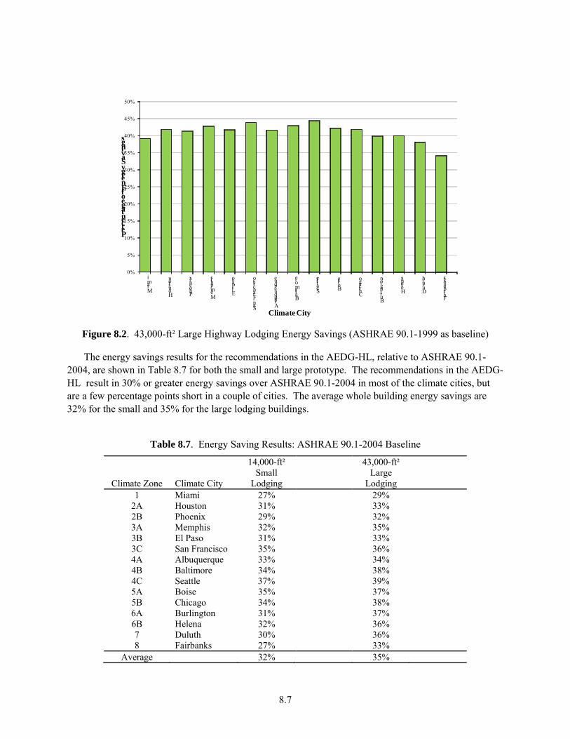
8.7
0%
5%
10%
15%
20%
25%
30%
35%
40%
45%
50%
Miami
Houston
Phoenix
Memphis
El-Paso
San-Francisco
Albuquerque
Baltimore
Seattle
Boise
Chicago
Burlington
Helena
Duluth
Fairbanks
Percentage of Energy Savings
Climate City Figure 8.2. 43,000-ft² Large Highway Lodging Energy Savings (ASHRAE 90.1-1999 as baseline)
The energy savings results for the recommendations in the AEDG-HL, relative to ASHRAE 90.1-2004, are shown in Table 8.7 for both the small and large prototype. The recommendations in the AEDG-HL result in 30% or greater energy savings over ASHRAE 90.1-2004 in most of the climate cities, but are a few percentage points short in a couple of cities. The average whole building energy savings are 32% for the small and 35% for the large lodging buildings.
Table 8.7. Energy Saving Results: ASHRAE 90.1-2004 Baseline
Climate Zone Climate City
14,000-ft² Small
Lodging
43,000-ft² Large
Lodging 1 Miami 27% 29%
2A Houston 31% 33% 2B Phoenix 29% 32% 3A Memphis 32% 35% 3B El Paso 31% 33% 3C San Francisco 35% 36% 4A Albuquerque 33% 34% 4B Baltimore 34% 38% 4C Seattle 37% 39% 5A Boise 35% 37% 5B Chicago 34% 38% 6A Burlington 31% 37% 6B Helena 32% 36% 7 Duluth 30% 36% 8 Fairbanks 27% 33%
Average 32% 35%

8.8
The energy end uses for each ASHRAE 90.1-1999 baseline and the advanced model are illustrated in Figure 8.3 and Figure 8.4 for both the small and large prototype buildings, respectively. Similarly, the energy end uses for each ASHRAE 90.1-2004 baseline and the advanced model are shown in Figure 8.5 and Figure 8.6 for both small and large lodging prototypes, respectively. In addition, the end-use data and percent savings in tabular format are shown in Appendix D.
Base
Adva
Base
Adva
Base
Adva
Base
Adva
Base
Adva
Base
Adva
Base
Adva
Base
Adva
Base
Adva
Base
Adva
Base
Adva
Base
Adva
Base
Adva
Base
Adva
Base
Adva
37% 39% 37%39%
39% 41%39%
39%42%
40%38%
35%37%
33%
29%
0
20
40
60
80
100
120
140
160
Miami(1A)
Houston(2A)
Pheoenix(2B)
Memphis(3A)
El Paso(3B)
San Franc. (3C)
Albuq. (4A)
Baltimore(4B)
Seattle(4C)
Boise (5A)
Chicago (5B)
Burlington (6A)
Helena (6B)
Duluth (7A)
Fairbanks (8A)
Site EUI (kBtu/ft
2-yr)
Climate City
SWHHeatingCoolingFansPumpsExterior LightsInterior LightsPlug Loads
Figure 8.3. 14,000-ft² Small Highway Lodging Energy End Use (ASHRAE 90.1-1999 as baseline)
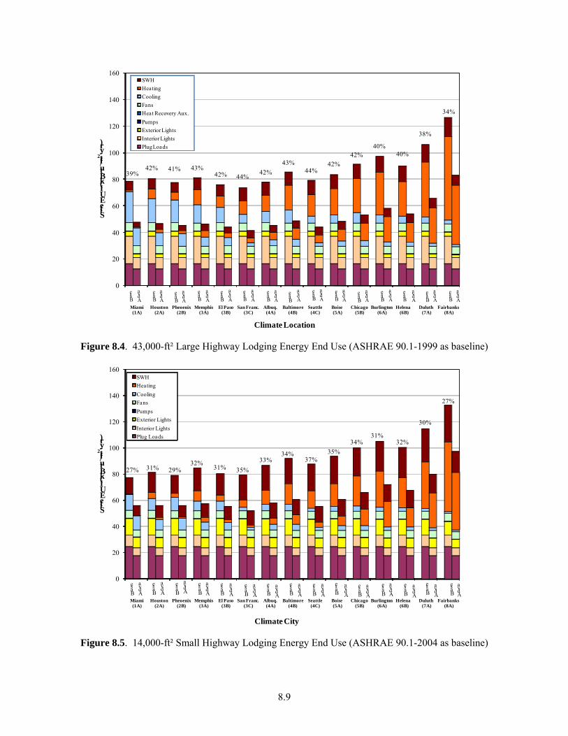
8.9
Base
Adva
Base
Adva
Base
Adva
Base
Adva
Base
Adva
Base
Adva
Base
Adva
Base
Adva
Base
Adva
Base
Adva
Base
Adva
Base
Adva
Base
Adva
Base
Adva
Base
Adva
39%42% 41% 43%
42% 44%42%
43%44%
42%42%
40%40%
38%
34%
0
20
40
60
80
100
120
140
160
Miami(1A)
Houston(2A)
Pheoenix(2B)
Memphis(3A)
El Paso(3B)
San Franc. (3C)
Albuq. (4A)
Baltimore(4B)
Seattle(4C)
Boise (5A)
Chicago (5B)
Burlington (6A)
Helena (6B)
Duluth (7A)
Fairbanks (8A)
Site EUI (kBtu/ft
2-yr)
Climate Location
SWHHeatingCoolingFansHeat Recovery Aux.PumpsExterior LightsInterior LightsPlug Loads
Figure 8.4. 43,000-ft² Large Highway Lodging Energy End Use (ASHRAE 90.1-1999 as baseline)
Base
Adva
Base
Adva
Base
Adva
Base
Adva
Base
Adva
Base
Adva
Base
Adva
Base
Adva
Base
Adva
Base
Adva
Base
Adva
Base
Adva
Base
Adva
Base
Adva
Base
Adva
27% 31% 29%32%
31% 35%33%
34%37%
35%34%
31%32%
30%
27%
0
20
40
60
80
100
120
140
160
Miami(1A)
Houston(2A)
Pheoenix(2B)
Memphis(3A)
El Paso(3B)
San Franc. (3C)
Albuq. (4A)
Baltimore(4B)
Seattle(4C)
Boise (5A)
Chicago (5B)
Burlington (6A)
Helena (6B)
Duluth (7A)
Fairbanks (8A)
Site EUI (kBtu/ft
2-yr)
Climate City
SWHHeatingCoolingFansPumpsExterior LightsInterior LightsPlug Loads
Figure 8.5. 14,000-ft² Small Highway Lodging Energy End Use (ASHRAE 90.1-2004 as baseline)
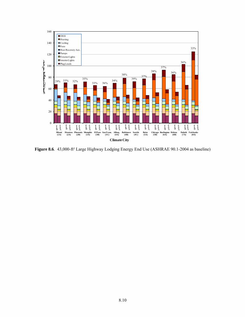
8.10
Base
Adva
Base
Adva
Base
Adva
Base
Adva
Base
Adva
Base
Adva
Base
Adva
Base
Adva
Base
Adva
Base
Adva
Base
Adva
Base
Adva
Base
Adva
Base
Adva
Base
Adva
29% 33% 32%35%
33% 36%34%
38%39%
37%
38%37%
36%
36%
33%
0
20
40
60
80
100
120
140
160
Miami(1A)
Houston(2A)
Pheoenix(2B)
Memphis(3A)
El Paso(3B)
San Franc. (3C)
Albuq. (4A)
Baltimore(4B)
Seattle(4C)
Boise (5A)
Chicago (5B)
Burlington (6A)
Helena (6B)
Duluth (7A)
Fairbanks (8A)
Site EUI (kBtu/ft
2-yr)
Climate City
SWHHeatingCoolingFansHeat Recovery Aux.PumpsExterior LightsInterior LightsPlug Loads
Figure 8.6. 43,000-ft² Large Highway Lodging Energy End Use (ASHRAE 90.1-2004 as baseline)

9.1
9.0 References
AHLA. 2007. The 2007 Lodging Industry Profile. American Hotel & Lodging Association, Washington, D.C. Last Accessed on September 2, 2008 at http://www.ahla.com/content.aspx?id=4214
ANSI/ASHRAE. 2001. ANSI/ASHRAE Standard 62-2001, Ventilation for Acceptable Indoor Air Quality. American Society of Heating, Refrigerating and Air-Conditioning Engineers, Atlanta, Georgia, 2001.
ANSI/ASHRAE. 2004. ANSI/SHRAE Standard 62.1-2004, Ventilation for Acceptable Indoor Air Quality. American Society of Heating, Refrigerating and Air-Conditioning Engineers, Atlanta, Georgia, 2004.
ANSI/ASHRAE/IESNA. 1999. ANSI/ASHRAE/IESNA Standard 90.1-1999, Energy Standard for Buildings Except Low-Rise Residential Buildings. American Society of Heating, Ventilating and Air-Conditioning Engineers, Inc., Atlanta, Georgia, 1999.
ANSI/ASHRAE/IESNA. 2004. ANSI/ASHRAE/IESNA Standard 90.1-2004, Energy Standard for Buildings Except Low-Rise Residential Buildings. American Society of Heating, Refrigerating and Air-Conditioning Engineers, Atlanta, Georgia.
ANSI/ASHRAE/IESNA. 2007. ANSI/ASHRAE/IESNA Standard 90.1-2007, Energy Standard for Buildings Except Low-Rise Residential Buildings. American Society of Heating, Refrigerating and Air-Conditioning Engineers, Atlanta, Georgia.
ASHRAE. 2005. Handbook: Fundamentals. American Society of Heating, Refrigerating and Air-Conditioning Engineers, Inc., Atlanta, Georgia, 2005.
ASHRAE. 2007. Handbook: HVAC Applications. American Society of Heating, Refrigerating and Air-Conditioning Engineers, Inc., Atlanta, Georgia, 2007.
ASHRAE 189.1P. 2007. Standard for the Design of High-Performance, Green Buildings Except Low-Rise Residential Buildings. First Draft for Public Review. American Society of Heating, Ventilating and Air-Conditioning Engineers, Inc., Atlanta, Georgia, 2007.
ASHRAE/IESNA. 1989. ASHRAE/IESNA Standard 90.1-1989, Energy Efficient Design of New Building Except Low-Rise Residential Buildings. American Society of Heating, Ventilating and Air-Conditioning Engineers, Inc., Atlanta, Georgia, 1989.
ASHRAE/AIA/IESNA/NBI/DOE. 2004. Advanced Energy Design Guide for Small Office Buildings: Achieving 30% Energy Savings Over ANSI/ASHRAE/IESNA Standard 90.1-1999, American Society of Heating, Refrigerating and Air-Conditioning Engineers, Atlanta, Georgia, 2004.
ASHRAE/AIA/IESNA/USGBC/DOE. 2006. Advanced Energy Design Guide for Small Retail Buildings: Achieving 30% Energy Savings Toward a Net Zero Energy Building. American Society of Heating, Refrigerating and Air-Conditioning Engineers, Atlanta, Georgia, 2006.
9.2
ASHRAE/AIA/IESNA/USGBC/DOE. 2007a. Advanced Energy Design Guide for K-12 School Buildings: Achieving 30% Energy Savings Toward a Net Zero Energy Building. American Society of Heating, Refrigerating and Air-Conditioning Engineers, Atlanta, Georgia, 2007.
ASHRAE/AIA/IESNA/USGBC/DOE. 2007b. Advanced Energy Design Guide for Warehouses and Self-K-12 School Buildings: Achieving 30% Energy Savings Toward a Net Zero Energy Building. American Society of Heating, Refrigerating and Air-Conditioning Engineers, Atlanta, Georgia, 2007.
Briggs R.L., R.G. Lucas, and Z.T. Taylor. 2003. “Climate Classification for Building Energy Codes and Standards: Part 1—Development Process.” ASHRAE Transactions 2003 (1) Page 4610. American Society of Heating, Refrigerating and Air-Conditioning Engineers, Inc., Atlanta, Georgia, 2003. CBECS. 2003. Commercial Buildings Energy Consumption Survey 2003, Energy Information Administration of U.S. Department of Energy, Washington, D.C. Last accessed on August 29, 2008 at http://www.eia.doe.gov/emeu/cbecs/contents.html
DOE. 2000. Screening Analysis for EPACT-Covered Commercial HVAC and Water-Heating Equipment. U.S. Department of Energy, Washington, D.C.
DOE. 2008. EnergyPlus Energy Simulation Software. Washington, D.C. U.S. Department of Energy. Last accessed on September 2, 2008 at http://www.energyplus.gov
Ducker Worldwide. 2001. 2000 U.S. Market for Residential and Specialty Air Conditioning: PTAC (Packaged Terminal Air Conditioning). HVAC0002. Final Report, March 2001. Ducker Industrial Standards, 6905 Telegraph Road Suite 300, Bloomfield Hills, MI 48301.
EIA. 2006. Commercial Buildings Energy Consumption Survey 2003, Energy Information Administration of U.S. Department of Energy, Washington, D.C. Last accessed on September 2, 2008 at http://www.eia.doe.gov/emeu/cbecs/contents.html
Eilert, P. 2000. High Albedo (Cool) Roofs – Codes and Standards Enhancement (CASE) Study. Pacific Gas and Electric Company, San Francisco, California.
Hampton Inn. 2008. The Hampton Inn prototype floor plans can be downloaded from: http://www.hamptonfranchise.com/Index.asp?S=3&P=23. Last accessed on September 2, 2008.
IECC. 2006. International Energy Conservation Code, 2006 Edition. International Code Council, Falls Church, Virginia.
IESNA. 1999. IESNA RP-33-99 Lighting for Exterior Environments. Illuminating Engineering Society of North America, 120 Wall Street, New York, NY.
Jarnagin, R.E., B. Liu, D.W. Winiarski, M.F. McBride, L. Suharli and D. Walden. 2006. Technical Support Document: Development of the Advanced Energy Design Guide for Small Office Buildings. November 2006. Pacific Northwest National Laboratory, PNNL-16250. Richland, Washington.

9.3
Liu, B., R.E. Jarnagin, D.W. Winiarski, W. Jiang, M.F. McBride and and G.C. Crall. 2006. Technical Support Document: Development of the Advanced Energy Design Guide for Small Retail Buildings, September, 2006. Pacific Northwest National Laboratory, PNNL-16031. Richland, Washington.
Liu, B., R.E. Jarnagin, W. Jiang and K. Gowri. 2007. Technical Support Document: Development of the Advanced Energy Design Guide for Small Warehouse and Self-Storage Buildings, December, 2007. Pacific Northwest National Laboratory, PNNL-17056. Richland, Washington.
LBNL. 2000. Cool Roofing Materials Database. Last accessed on September 2, 2008 at http://eetd.lbl.gov/coolroofs/
LBNL. 2004. Lawrence Berkeley National Laboratory and James J. Hirsch & Associates. DOE-2.2 Building Energy Use and Cost Analysis Program Documentation. Last Accessed on September 2, 2008 at http://doe2.com/DOE2/index.html#doe22docs
Persily, A.K. 1998. “Airtightness of Commercial and Institutional Buildings: Blowing Holes in the Myth of Tight Buildings”. Proceedings of Thermal Performance of the Exterior Envelopes of Buildings VII, pp. 829-837.
PTAC. 2008. Packaged Terminal Air Conditioners and Heat Pumps Energy Conservation Standard Notice of Proposed Rulemaking Technical Support Document. U.S. Department of Energy, Washington, D.C.
Pless, S., P. Torcellini, and N. Long. 2007. Technical Support Document: Development of the Advanced Energy Design Guide for K-12 Schools—30% Energy Savings. September, 2007. National Renewable Energy Laboratory, NREL/TP-550-42114. Golden, Colorado.
Richman, E.E., E. Rauch, J. Knappek, J. Phillips, K. Petty and P. Lopez-Rangel. 2008. “National Commercial Construction Characteristics and Compliance with Building Energy Codes: 1999-2007”. 2008 ACEEE Summery Study on Energy Efficiency in Buildings, Pacific Grove, California, August 17-22, 2008.
R.S. Means. 2008. RS Means CostWorks 2008.http://www.meanscostworks.com. Accessed August, 2008.
Roberson, J.A., G.K. Homan, A. Mahajan, B. Nordman, C. Webber, R.E. Brown, M. McWhinney and J.G. Koomey. 2002. Energy Use and Power Levels in New Monitors and Personal Computers. LBNL-48581. July 2002. Lawrence Berkeley National Laboratory, Berkeley, California.
Sachs, H. M. 2005. “Opportunities for Elevator Energy Efficiency Improvements. American Council for an Energy-Efficient Economy”. Washington DC.
USGS. 2006. U.S. Geology Survey. Last accessed on September 2, 2008 at http://geonames.usgs.gov/domestic/download_data.htm
Wassmer, M., and M. J. Brandemuehl. 2006. “Effect of Data Availability on Modeling of Residential Air Conditioners and Heat Pumps for Energy Calculations”. ASHRAE Transactions 111(1), pp. 214-225.


Appendix A
Building Energy Modeling Schedules

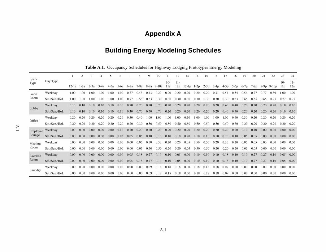
A.1
A.1
Appendix A
Building Energy Modeling Schedules
Table A.1. Occupancy Schedules for Highway Lodging Prototypes Energy Modeling
Space Type Day Type
1 2 3 4 5 6 7 8 9 10 11 12 13 14 15 16 17 18 19 20 21 22 23 24
12-1a 1-2a 2-3a 3-4a 4-5a 5-6a 6-7a 7-8a 8-9a 9-10a10-11a
11-12p 12-1p 1-2p 2-3p 3-4p 4-5p 5-6p 6-7p 7-8p 8-9p 9-10p
10-11p
11-12a
Guest Room
Weekday 1.00 1.00 1.00 1.00 1.00 1.00 0.77 0.43 0.43 0.20 0.20 0.20 0.20 0.20 0.20 0.31 0.54 0.54 0.54 0.77 0.77 0.89 1.00 1.00
Sat./Sun./Hol. 1.00 1.00 1.00 1.00 1.00 1.00 0.77 0.53 0.53 0.30 0.30 0.30 0.30 0.30 0.30 0.30 0.30 0.53 0.65 0.65 0.65 0.77 0.77 0.77
Lobby Weekday 0.10 0.10 0.10 0.10 0.10 0.30 0.70 0.70 0.70 0.70 0.20 0.20 0.20 0.20 0.20 0.20 0.40 0.40 0.20 0.20 0.20 0.20 0.10 0.10
Sat./Sun./Hol. 0.10 0.10 0.10 0.10 0.10 0.10 0.30 0.70 0.70 0.70 0.20 0.20 0.20 0.20 0.20 0.20 0.40 0.40 0.20 0.20 0.20 0.20 0.10 0.10
Office Weekday 0.20 0.20 0.20 0.20 0.20 0.20 0.30 0.40 1.00 1.00 1.00 1.00 0.50 1.00 1.00 1.00 1.00 0.40 0.30 0.20 0.20 0.20 0.20 0.20
Sat./Sun./Hol. 0.20 0.20 0.20 0.20 0.20 0.20 0.20 0.30 0.50 0.50 0.50 0.50 0.50 0.50 0.50 0.50 0.50 0.30 0.20 0.20 0.20 0.20 0.20 0.20
Employee Lounge
Weekday 0.00 0.00 0.00 0.00 0.00 0.10 0.10 0.20 0.20 0.20 0.20 0.20 0.70 0.20 0.20 0.20 0.20 0.20 0.10 0.10 0.00 0.00 0.00 0.00
Sat./Sun./Hol. 0.00 0.00 0.00 0.00 0.00 0.05 0.05 0.05 0.10 0.10 0.10 0.10 0.20 0.10 0.10 0.10 0.10 0.10 0.05 0.05 0.00 0.00 0.00 0.00
Meeting Room
Weekday 0.00 0.00 0.00 0.00 0.00 0.00 0.00 0.05 0.50 0.50 0.20 0.20 0.05 0.50 0.50 0.20 0.20 0.20 0.05 0.05 0.00 0.00 0.00 0.00
Sat./Sun./Hol. 0.00 0.00 0.00 0.00 0.00 0.00 0.00 0.05 0.50 0.50 0.20 0.20 0.05 0.50 0.50 0.20 0.20 0.20 0.05 0.05 0.00 0.00 0.00 0.00
Exercise Room
Weekday 0.00 0.00 0.00 0.00 0.00 0.00 0.05 0.18 0.27 0.10 0.10 0.05 0.00 0.10 0.10 0.10 0.18 0.10 0.10 0.27 0.27 0.10 0.05 0.00
Sat./Sun./Hol. 0.00 0.00 0.00 0.00 0.00 0.00 0.05 0.18 0.27 0.10 0.10 0.05 0.00 0.10 0.10 0.10 0.18 0.10 0.10 0.27 0.27 0.10 0.05 0.00
Laundry Weekday 0.00 0.00 0.00 0.00 0.00 0.00 0.00 0.00 0.09 0.18 0.18 0.18 0.00 0.18 0.18 0.18 0.09 0.00 0.00 0.00 0.00 0.00 0.00 0.00
Sat./Sun./Hol. 0.00 0.00 0.00 0.00 0.00 0.00 0.00 0.00 0.09 0.18 0.18 0.18 0.00 0.18 0.18 0.18 0.09 0.00 0.00 0.00 0.00 0.00 0.00 0.00

A.2
A.2
Table A.2. Lighting Schedules for Highway Lodging Prototypes Energy Modeling
Space Type Day Type 1 2 3 4 5 6 7 8 9 10 11 12 13 14 15 16 17 18 19 20 21 22 23 24
12-1a 1-2a 2-3a 3-4a 4-5a 5-6a 6-7a 7-8a 8-9a 9-10a10-11a
11-12p 12-1p 1-2p 2-3p 3-4p 4-5p 5-6p 6-7p 7-8p 8-9p 9-10p
10-11p
11-12a
Guest Room (Base)
Weekday 0.22 0.17 0.11 0.11 0.11 0.22 0.44 0.56 0.44 0.44 0.28 0.28 0.28 0.28 0.28 0.28 0.28 0.28 0.67 0.89 1.00 0.89 0.67 0.33 Sat./Sun./Hol. 0.26 0.26 0.11 0.11 0.11 0.11 0.41 0.41 0.56 0.56 0.41 0.33 0.33 0.33 0.33 0.33 0.33 0.33 0.85 1.00 1.00 1.00 0.85 0.41
Guest Room (Adva)
Weekday 0.22 0.17 0.11 0.11 0.11 0.22 0.44 0.56 0.44 0.44 0.10 0.10 0.10 0.10 0.10 0.10 0.10 0.10 0.67 0.89 1.00 0.89 0.67 0.33 Sat./Sun./Hol. 0.26 0.26 0.11 0.11 0.11 0.11 0.41 0.41 0.56 0.56 0.10 0.10 0.10 0.10 0.10 0.10 0.10 0.10 0.85 1.00 1.00 1.00 0.85 0.41
Lobby Weekday 0.50 0.50 0.50 0.50 0.50 0.60 1.00 1.00 1.00 1.00 1.00 1.00 1.00 1.00 1.00 1.00 1.00 1.00 1.00 1.00 1.00 0.60 0.50 0.50 Sat./Sun./Hol. 0.50 0.50 0.50 0.50 0.50 0.60 1.00 1.00 1.00 1.00 1.00 1.00 1.00 1.00 1.00 1.00 1.00 1.00 1.00 1.00 1.00 0.60 0.50 0.50
Office (Base) Weekday 0.50 0.50 0.50 0.50 0.50 0.50 0.50 0.61 0.90 0.90 0.90 0.90 0.80 0.90 0.90 0.90 0.90 0.61 0.50 0.50 0.50 0.50 0.50 0.50 Sat./Sun./Hol. 0.50 0.50 0.50 0.50 0.50 0.50 0.50 0.61 0.90 0.90 0.90 0.90 0.80 0.90 0.90 0.90 0.90 0.61 0.50 0.50 0.50 0.50 0.50 0.50
Office (Adva) Weekday 0.43 0.43 0.43 0.43 0.43 0.43 0.43 0.52 0.77 0.77 0.77 0.77 0.68 0.77 0.77 0.77 0.77 0.52 0.43 0.43 0.43 0.43 0.43 0.43 Sat./Sun./Hol. 0.43 0.43 0.43 0.43 0.43 0.43 0.43 0.52 0.77 0.77 0.77 0.77 0.68 0.77 0.77 0.77 0.77 0.52 0.43 0.43 0.43 0.43 0.43 0.43
Employee Lounge
Weekday 0.05 0.05 0.05 0.05 0.05 0.15 0.40 0.50 1.00 1.00 1.00 1.00 1.00 1.00 1.00 1.00 1.00 1.00 0.50 0.40 0.15 0.15 0.05 0.05 Sat./Sun./Hol. 0.05 0.05 0.05 0.05 0.05 0.15 0.30 0.40 0.60 0.60 0.60 0.60 0.60 0.60 0.60 0.60 0.60 0.60 0.40 0.30 0.15 0.15 0.05 0.05
Meeting Room (Base)
Weekday 0.00 0.00 0.00 0.00 0.00 0.20 0.30 0.50 1.00 1.00 1.00 1.00 1.00 1.00 1.00 1.00 1.00 1.00 0.50 0.30 0.20 0.05 0.00 0.00 Sat./Sun./Hol. 0.00 0.00 0.00 0.00 0.00 0.20 0.30 0.50 1.00 1.00 1.00 1.00 1.00 1.00 1.00 1.00 1.00 1.00 0.50 0.30 0.20 0.05 0.00 0.00
Meeting Room (Adva)
Weekday 0.00 0.00 0.00 0.00 0.00 0.20 0.30 0.50 1.00 1.00 1.00 1.00 0.70 1.00 1.00 1.00 1.00 1.00 0.50 0.30 0.20 0.05 0.00 0.00 Sat./Sun./Hol. 0.00 0.00 0.00 0.00 0.00 0.20 0.30 0.50 1.00 1.00 1.00 1.00 0.70 1.00 1.00 1.00 1.00 1.00 0.50 0.30 0.20 0.05 0.00 0.00
Exercise Room (Base)
Weekday 0.00 0.00 0.00 0.00 0.00 0.00 0.50 1.00 1.00 1.00 1.00 1.00 1.00 1.00 1.00 1.00 1.00 1.00 1.00 1.00 1.00 1.00 0.50 0.00 Sat./Sun./Hol. 0.00 0.00 0.00 0.00 0.00 0.00 0.50 1.00 1.00 1.00 1.00 1.00 1.00 1.00 1.00 1.00 1.00 1.00 1.00 1.00 1.00 1.00 0.50 0.00
Exercise Room (Adva)
Weekday 0.00 0.00 0.00 0.00 0.00 0.00 0.50 0.70 0.70 0.70 0.70 0.70 0.70 0.70 0.70 0.70 0.70 0.70 0.70 0.70 0.70 0.70 0.50 0.00 Sat./Sun./Hol. 0.00 0.00 0.00 0.00 0.00 0.00 0.50 0.70 0.70 0.70 0.70 0.70 0.70 0.70 0.70 0.70 0.70 0.70 0.70 0.70 0.70 0.70 0.50 0.00
Laundry Room
Weekday 0.00 0.00 0.00 0.00 0.00 0.00 0.00 0.00 1.00 1.00 1.00 1.00 1.00 1.00 1.00 1.00 1.00 0.00 0.00 0.00 0.00 0.00 0.00 0.00 Sat./Sun./Hol. 0.00 0.00 0.00 0.00 0.00 0.00 0.00 0.00 1.00 1.00 1.00 1.00 1.00 1.00 1.00 1.00 1.00 0.00 0.00 0.00 0.00 0.00 0.00 0.00
Corridor /Stairs
Weekday 1.00 1.00 1.00 1.00 1.00 1.00 1.00 1.00 1.00 1.00 1.00 1.00 1.00 1.00 1.00 1.00 1.00 1.00 1.00 1.00 1.00 1.00 1.00 1.00 Sat./Sun./Hol. 1.00 1.00 1.00 1.00 1.00 1.00 1.00 1.00 1.00 1.00 1.00 1.00 1.00 1.00 1.00 1.00 1.00 1.00 1.00 1.00 1.00 1.00 1.00 1.00
Storage /Mechanical
Weekday 0.10 0.10 0.10 0.10 0.10 0.10 0.10 0.20 0.40 0.40 0.40 0.40 0.40 0.40 0.40 0.40 0.40 0.40 0.20 0.20 0.20 0.20 0.10 0.10 Sat./Sun./Hol. 0.10 0.10 0.10 0.10 0.10 0.10 0.10 0.20 0.40 0.40 0.40 0.40 0.40 0.40 0.40 0.40 0.40 0.40 0.20 0.20 0.20 0.20 0.10 0.10
Exterior Weekday 1.00 1.00 1.00 1.00 1.00 1.00 1.00 0.00 0.00 0.00 0.00 0.00 0.00 0.00 0.00 0.00 0.00 0.00 0.00 1.00 1.00 1.00 1.00 1.00 Sat./Sun./Hol. 1.00 1.00 1.00 1.00 1.00 1.00 1.00 0.00 0.00 0.00 0.00 0.00 0.00 0.00 0.00 0.00 0.00 0.00 0.00 1.00 1.00 1.00 1.00 1.00
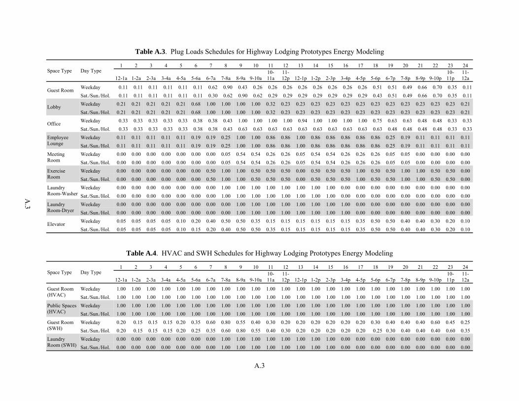
A.3
A.3
Table A.3. Plug Loads Schedules for Highway Lodging Prototypes Energy Modeling
Space Type Day Type 1 2 3 4 5 6 7 8 9 10 11 12 13 14 15 16 17 18 19 20 21 22 23 24
12-1a 1-2a 2-3a 3-4a 4-5a 5-6a 6-7a 7-8a 8-9a 9-10a10-11a
11-12p 12-1p 1-2p 2-3p 3-4p 4-5p 5-6p 6-7p 7-8p 8-9p 9-10p
10-11p
11-12a
Guest Room Weekday 0.11 0.11 0.11 0.11 0.11 0.11 0.62 0.90 0.43 0.26 0.26 0.26 0.26 0.26 0.26 0.26 0.26 0.51 0.51 0.49 0.66 0.70 0.35 0.11Sat./Sun./Hol. 0.11 0.11 0.11 0.11 0.11 0.11 0.30 0.62 0.90 0.62 0.29 0.29 0.29 0.29 0.29 0.29 0.29 0.43 0.51 0.49 0.66 0.70 0.35 0.11
Lobby Weekday 0.21 0.21 0.21 0.21 0.21 0.68 1.00 1.00 1.00 1.00 0.32 0.23 0.23 0.23 0.23 0.23 0.23 0.23 0.23 0.23 0.23 0.23 0.23 0.21 Sat./Sun./Hol. 0.21 0.21 0.21 0.21 0.21 0.68 1.00 1.00 1.00 1.00 0.32 0.23 0.23 0.23 0.23 0.23 0.23 0.23 0.23 0.23 0.23 0.23 0.23 0.21
Office Weekday 0.33 0.33 0.33 0.33 0.33 0.38 0.38 0.43 1.00 1.00 1.00 1.00 0.94 1.00 1.00 1.00 1.00 0.75 0.63 0.63 0.48 0.48 0.33 0.33Sat./Sun./Hol. 0.33 0.33 0.33 0.33 0.33 0.38 0.38 0.43 0.63 0.63 0.63 0.63 0.63 0.63 0.63 0.63 0.63 0.63 0.48 0.48 0.48 0.48 0.33 0.33
Employee Lounge
Weekday 0.11 0.11 0.11 0.11 0.11 0.19 0.19 0.25 1.00 1.00 0.86 0.86 1.00 0.86 0.86 0.86 0.86 0.86 0.25 0.19 0.11 0.11 0.11 0.11 Sat./Sun./Hol. 0.11 0.11 0.11 0.11 0.11 0.19 0.19 0.25 1.00 1.00 0.86 0.86 1.00 0.86 0.86 0.86 0.86 0.86 0.25 0.19 0.11 0.11 0.11 0.11
Meeting Room
Weekday 0.00 0.00 0.00 0.00 0.00 0.00 0.00 0.05 0.54 0.54 0.26 0.26 0.05 0.54 0.54 0.26 0.26 0.26 0.05 0.05 0.00 0.00 0.00 0.00 Sat./Sun./Hol. 0.00 0.00 0.00 0.00 0.00 0.00 0.00 0.05 0.54 0.54 0.26 0.26 0.05 0.54 0.54 0.26 0.26 0.26 0.05 0.05 0.00 0.00 0.00 0.00
Exercise Room
Weekday 0.00 0.00 0.00 0.00 0.00 0.00 0.50 1.00 1.00 0.50 0.50 0.50 0.00 0.50 0.50 0.50 1.00 0.50 0.50 1.00 1.00 0.50 0.50 0.00 Sat./Sun./Hol. 0.00 0.00 0.00 0.00 0.00 0.00 0.50 1.00 1.00 0.50 0.50 0.50 0.00 0.50 0.50 0.50 1.00 0.50 0.50 1.00 1.00 0.50 0.50 0.00
Laundry Room-Washer
Weekday 0.00 0.00 0.00 0.00 0.00 0.00 0.00 1.00 1.00 1.00 1.00 1.00 1.00 1.00 1.00 0.00 0.00 0.00 0.00 0.00 0.00 0.00 0.00 0.00 Sat./Sun./Hol. 0.00 0.00 0.00 0.00 0.00 0.00 0.00 1.00 1.00 1.00 1.00 1.00 1.00 1.00 1.00 0.00 0.00 0.00 0.00 0.00 0.00 0.00 0.00 0.00
Laundry Room-Dryer
Weekday 0.00 0.00 0.00 0.00 0.00 0.00 0.00 0.00 1.00 1.00 1.00 1.00 1.00 1.00 1.00 1.00 0.00 0.00 0.00 0.00 0.00 0.00 0.00 0.00 Sat./Sun./Hol. 0.00 0.00 0.00 0.00 0.00 0.00 0.00 0.00 1.00 1.00 1.00 1.00 1.00 1.00 1.00 1.00 0.00 0.00 0.00 0.00 0.00 0.00 0.00 0.00
Elevator Weekday 0.05 0.05 0.05 0.05 0.10 0.20 0.40 0.50 0.50 0.35 0.15 0.15 0.15 0.15 0.15 0.15 0.35 0.50 0.50 0.40 0.40 0.30 0.20 0.10 Sat./Sun./Hol. 0.05 0.05 0.05 0.05 0.10 0.15 0.20 0.40 0.50 0.50 0.35 0.15 0.15 0.15 0.15 0.15 0.35 0.50 0.50 0.40 0.40 0.30 0.20 0.10
Table A.4. HVAC and SWH Schedules for Highway Lodging Prototypes Energy Modeling
Space Type Day Type 1 2 3 4 5 6 7 8 9 10 11 12 13 14 15 16 17 18 19 20 21 22 23 24
12-1a 1-2a 2-3a 3-4a 4-5a 5-6a 6-7a 7-8a 8-9a 9-10a10-11a
11-12p 12-1p 1-2p 2-3p 3-4p 4-5p 5-6p 6-7p 7-8p 8-9p 9-10p
10-11p
11-12a
Guest Room (HVAC)
Weekday 1.00 1.00 1.00 1.00 1.00 1.00 1.00 1.00 1.00 1.00 1.00 1.00 1.00 1.00 1.00 1.00 1.00 1.00 1.00 1.00 1.00 1.00 1.00 1.00 Sat./Sun./Hol. 1.00 1.00 1.00 1.00 1.00 1.00 1.00 1.00 1.00 1.00 1.00 1.00 1.00 1.00 1.00 1.00 1.00 1.00 1.00 1.00 1.00 1.00 1.00 1.00
Public Spaces (HVAC)
Weekday 1.00 1.00 1.00 1.00 1.00 1.00 1.00 1.00 1.00 1.00 1.00 1.00 1.00 1.00 1.00 1.00 1.00 1.00 1.00 1.00 1.00 1.00 1.00 1.00 Sat./Sun./Hol. 1.00 1.00 1.00 1.00 1.00 1.00 1.00 1.00 1.00 1.00 1.00 1.00 1.00 1.00 1.00 1.00 1.00 1.00 1.00 1.00 1.00 1.00 1.00 1.00
Guest Room (SWH)
Weekday 0.20 0.15 0.15 0.15 0.20 0.35 0.60 0.80 0.55 0.40 0.30 0.20 0.20 0.20 0.20 0.20 0.20 0.30 0.40 0.40 0.40 0.60 0.45 0.25 Sat./Sun./Hol. 0.20 0.15 0.15 0.15 0.20 0.25 0.35 0.60 0.80 0.55 0.40 0.30 0.20 0.20 0.20 0.20 0.20 0.25 0.30 0.40 0.40 0.40 0.60 0.35
Laundry Room (SWH)
Weekday 0.00 0.00 0.00 0.00 0.00 0.00 0.00 1.00 1.00 1.00 1.00 1.00 1.00 1.00 1.00 0.00 0.00 0.00 0.00 0.00 0.00 0.00 0.00 0.00 Sat./Sun./Hol. 0.00 0.00 0.00 0.00 0.00 0.00 0.00 1.00 1.00 1.00 1.00 1.00 1.00 1.00 1.00 0.00 0.00 0.00 0.00 0.00 0.00 0.00 0.00 0.00


Appendix B
Building Prototypes Model Assumptions

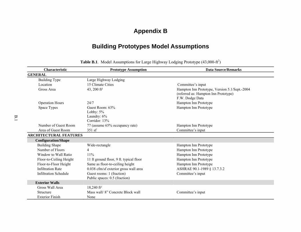
B.1
Appendix B
Building Prototypes Model Assumptions
Table B.1. Model Assumptions for Large Highway Lodging Prototype (43,000-ft2)
Characteristic Prototype Assumption Data Source/Remarks GENERAL Building Type Large Highway Lodging Location 15 Climate Cities Committee’s input Gross Area 43, 200 ft² Hampton Inn Prototype, Version 5.1/Sept.-2004
(referred as: Hampton Inn Prototype) F.W. Dodge Data
Operation Hours 24/7 Hampton Inn Prototype Space Types Guest Room: 63%
Lobby: 5% Laundry: 6% Corridor: 13%
Hampton Inn Prototype
Number of Guest Room 77 (assume 65% occupancy rate) Hampton Inn Prototype Area of Guest Room 351 sf Committee’s input ARCHITECTURAL FEATURES Configuration/Shape Building Shape Wide-rectangle Hampton Inn Prototype Number of Floors 4 Hampton Inn Prototype Window to Wall Ratio 11% Hampton Inn Prototype Floor-to-Ceiling Height 11 ft ground floor, 9 ft. typical floor Hampton Inn Prototype Floor-to-Floor Height Same as floor-to-ceiling height Hampton Inn Prototype Infiltration Rate 0.038 cfm/sf exterior gross wall area ASHRAE 90.1-1989 § 13.7.3.2 Infiltration Schedule Guest rooms: 1 (fraction)
Public spaces: 0.5 (fraction) Committee’s input
Exterior Walls Gross Wall Area 18,240 ft² Structure Mass wall/ 8” Concrete Block wall Committee’s input Exterior Finish None

B.2
Table B.1. (contd)
Characteristic Prototype Assumption Data Source/Remarks Roof Gross Roof Area 10, 800 ft² Structure Steel deck with rigid insulation Committee’s input Exterior Finish Single-ply roof membrane Committee’s input Fenestration/Windows Total Fenestration Area 1, 985 ft² (Typical window size is 4’x5’) Window
Shading/Overhangs None Hampton Inn Prototype
2003 CBECS Opaque Doors N.A. (all doors are glazed, treated as fenestration) Hampton Inn Prototype INTERNAL LOADS Occupancy Peak Number of People Guest Room: 1.5
Lobby: 53 Office: 10 Laundry/Exercise Room:11 Meeting Room: 43 Corridor/Stairs/Storage: 0
General Practice ASHRAE 62.1-2001
Occupancy Schedule See under Schedules Committee’s input Lighting Daylighting Responsive
Lighting Control No Committee’s input
Skylights No 2003 CBECS Plug Load Peak Power Density, w/sf Lobby: 2.42
Corridors/stairs: 0.0 Office: 1.28 Meeting Room: 0.57 Exercise Room: 1.73
Engineering calculation
Equipment Schedule See under Schedules Committee’s input Elevator Power Consumption
(kWh/year) 4161 Engineering calculation
Equipment Schedule See under Schedules Committee’s input

B.3
Table B.1. (contd)
Characteristic Prototype Assumption Data Source/Remarks HVAC SYSTEM System Type Heating/ Cooling Type - Guest room: PTAC/PTHP, make-up air unit with DX
cooling and furnace (MAU) - Public space: Split system; unit heater for
mechanical room, stairs
Base: 2003 CBECS, NC3, Ducker Report AEDG: Committee’s input
Ventilation Outdoor Air Supply - Guest room: 30 cfm/room
- Corridor: Mechanical room: 0.05 cfm/ft2 - Lobby/ Employee lounge: 15 cfm/person - Laundry: 25 cfm/person - Office/Meeting room/ Exercise room: 20
cfm/person - Restroom: 50 cfm/person - Storage: 0 cfm
ASHRAE 62.1-2001
Guest Room Exhaust Air 30 cfm/room ASHRAE 62.1-2001 Demanded Control
Ventilation None Committee’s input
SERVICE WATER HEATING Water Heater Water Heater Type Gas storage water heater Committee’s input Tank Capacity, gallon 300 gallon ASHRAE Handbook Application 2007 Chapter 49 Hot Water Temperature, °F 140 General design practice

B.4
Table B.2. Model Assumptions for Small Highway Lodging Prototype (14,000-ft2)
Characteristic Baseline Data Source/Remarks GENERAL Building Type Small Highway Lodging Location 15 Climate Cities Committee’s input Gross Area 14, 000 ft² CBECS 2003 Operation Hours 24/7 CBECS 2003 Space Types Guest Room: 90%
Office: 5% Laundry: 5%
Committee’s input
Number of Guest Room 44 (assume 65% occupancy rate) AHLA Industry Profile Area of Guest Room 288 sf Committee’s input ARCHITECTURAL FEATURES Configuration/Shape Building Shape Wide-rectangle CBECS 2003 Number of Floors 2 CBECS 2003 Window to Wall Ratio 11 % CBECS 2003 Floor-to-Floor Height 9 ft. Committee’s input Infiltration Rate 0.038 cfm/sf of exterior wall area ASHRAE 90.1-1989 § 13.7.3.2
Infiltration Schedule AlwaysOn Committee’s input Exterior Walls Gross Wall Area 11, 500 ft² Structure Wood-frame wall Committee’s input Exterior Finish Stucco cladding CBECS 2003 Roof Gross Roof Area 8, 350 ft² Structure Attic Roof with Wood Joists CBECS 2003 Exterior Finish Asphalt Shingles CBECS 2003 Fenestration/Windows Total fenestration area 1,300 ft² (typical window size is 4’x5’) Window
Shading/Overhangs None Hilton Prototype
2003 CBECS Opaque Doors Size 3’ x 7’, Opaque door, Swinging Hilton Prototype Door schedule

B.5
Table B.2. (contd)
Characteristic Baseline Data Source/Remarks INTERNAL LOADS Occupancy Peak Number of People Guest Room: 1.5
Lobby: 10 Laundry: 11
General Practice ASHRAE 62.1-2001
Occupancy Schedule See under Schedules Committee’s input Lighting Daylighting Responsive
Lighting Control No Committee’s input
Skylights No 2003 CBECS Plug Load Peak Power Density, w/sf Office: 1.28
Engineering Calculation Committee input – 60lb washer and 75 lb dryer, assuming 9 lbs of wash load per room
Equipment Schedule See under Schedules Committee’s input HVAC SYSTEM System Type Heating/ Cooling Type PTAC/PTHP Base: 2003 CBECS, NC3, Ducker Report
AEDG: Committee’s input Ventilation Outdoor Air Supply - Guest room: 30 cfm/room
- Laundry: 25 cfm/person - Office room: 20 cfm/person
ASHRAE 62.1-2001
Ventilation Control Always On Committee’s input Guest Room Exhaust Air 30 cfm/room ASHRAE 62.1-2001 Energy Recovery
Ventilator None Committee’s input
Demanded Control Ventilation
None
Economizer None ASHRAE 90.1-1999 SERVICE WATER HEATING Water Heater Water Heater Type Gas storage water heater Committee’s input Tank Capacity, gallon 200 gallon ASHRAE Handbook Application 2007 49.14 Hot Water Temperature, °F 140 General design practice


Appendix C
Baseline and Advanced Buildings Model Assumptions


C.1
Appendix C
Baseline and Advanced Buildings Model Assumptions
Table C.1. Baseline and Advanced Buildings Model Assumptions for Large Highway Lodging Prototype (43,000 ft2)
Characteristic Baseline AEDG Data Source/Remarks ARCHITECTURAL FEATURES Exterior Walls Insulation (Res/NonRes) Zone 1, 2: R-5.7ci/NR
Zone 3: R-7.6ci/R-5.7ci Zone 4: R-9.5ci/R-5.7ci Zone 5: R-11.4ci/R-7.6ci Zone 6: R-11.4ci/R-9.5ci Zone 7: R-13.3ci/R-11.4ci Zone 8: R-15.2ci/ R-13.3ci
Zone 1: R-5.7ci Zone 2: R-7.6ci Zone 3: R-11.4ci Zone 4, 5, 6: R-13.3ci Zone 7: R-15.2ci Zone 8: R-25ci
Base: ASHRAE 90.1-1999 AEDG: AEDG-HL
Overall U-factor Zone 1, 2: U-0.151/U-0.58 Zone 3: U-0.123/U-0.151 Zone 4: U-0.104/ U-0.151 Zone 5: U-0.090/ U-0.123 Zone 6: U-0.090/ U-0.104 Zone 7: U-0.080/ U-0.090 Zone 8: U-0.071/ U-0.080
Zone 1: U-0.151 Zone 2: U-0.123 Zone 3: U-0.090 Zone 4, 5, 6: U-0.080 Zone 7: U-0.071 Zone 8: U-0.049
ASHRAE 90.1-1999 Table A-9
Roof Insulation (Res/NonRes) Zones 1-7: R-15ci/R-15ci (except for San
Francisco, baseline is R-10ci) Zone 8: R-20ci/R-20ci
Zones 1-6: R-20ci Zone 7: R-25ci Zone 8: R-30ci
Base: ASHRAE 90.1-1999 AEDG: AEDG-HL
Overall U-factor Zones 1-7: U-0.063 (except for San Francisco, baseline is U-0.093) Zone 8: U-0.048
Zones 1-6: U-0.048 Zone-7: U-0.039 Zone-8: U-0.032
ASHRAE 90.1-1999 Table A-2
Solar Reflectance 0.23 (grey EPDM) Zones 1-3: 0.78 (white T-EPDM) Zones 4-8: 0.23
ASHRAE 2001 Fundamentals, Chapter 38 Asphalt shingle properties from http://eetd.lbl.gov/coolroof/asshingl.htm

C.2
Table C.1. (contd)
Characteristic Baseline AEDG Data Source/Remarks Slab-On-Grade Floor Floor Insulation Zones 1-5: None
Zone 6, 7: R-10 for 24 in. Zone 8: R-15 for 24 in.
Zones 1 to 3: None Zones 4, 5: R-10 for 24 in. Zone 6, 7: R-15 for 24 in. Zone 8: R-20 for 24 in.
Base: ASHRAE 90.1-1999 AEDG: AEDG-HL
Floor F-factor Zones 1-5: F-0.73 Zone 6, 7: F-0.54 Zone 8: F-0.52
Zones 1 to 3: F-0.73 Zones 4, 5: F-0.54 Zone 6, 7: F-0.52 Zone 8: F-0.51
ASHRAE 90.1-1999 Table A-16
Fenestration/Windows Window Type Zones 1, 2, 3C: Single-pane windows;
All other zones: Double pane windows Zones 1, 2, 3: Double-pane windows All other zones: Triple pane windows
Base: ASHRAE 90.1-1999 AEDG: AEDG-HL
Total U-factor Zones 1, 2, 3(B-12): U-1.22 Zones 3(B-10, 13) -7: U-0.57 Zone 8: U-0.46
Zone 1: U-0.56 Zone 2: U-0.45 Zone 3: U-0.41 Zones 4: U-0.38 Zones 5, 6: U-0.35 Zone 7: U-0.33 Zone 8: U-0.25
Base: ASHRAE 90.1-1999 AEDG: AEDG-HL All climate zone references are based on ASHRAE 90.1-2004. The baseline climate zones with B-x in parenthesis refer to 90.1-1999 Appendix-B table number for certain locations within a new climate zone that have different envelope requirements in the older climate zone.
SHGC (Res/NonRes) Zones 1, 2(B-5), 3A, 3B: 0.25 Zone 2(B-6): 0.44/0.25 Zone 3C: 0.61 Zones 4, 5, 6: 0.39 Zone 7: 0.49 Zone 8: NR
Zone 1-3: 0.25 Zones 4-6: 0.40 Zone 7: 0.41 Zone 8: 0.38
Actual Glazing Input Zones 1, 2(B-5) : U-1.22/SHGC-0.25 Zone 2(B-6) : U-1.22/SHGC-0.44 Zones 3A, 3B : U-0.57/SHGC-0.25 Zones 3C: U-1.22/SHGC-0.61 Zones 4, 5, 6: U-0.57/SHGC-0.39 Zone 7: U-0.57/SHGC-0.49 Zone 8: U-0.46/SHGC-0.47
Zone 1: U-0.52/SHGC-0.26 Zone 2: U-0.43/SHGC-0.27 Zone 3: U-0.42/SHGC-0.24 Zone 4, 5, 6, 7: U-0.40/SHGC-0.42 Zone 8: U-0.265/SHGC-0.371
Baseline: EnergyPlus hypothetical glass input to match the required glazing U-factor and SHGC AEDG: Window type chosen from EnergyPlus Library with the closest matching U-factor/SHGC

C.3
Table C.1. (contd)
Characteristic Baseline AEDG Data Source/Remarks INTERNAL LOADS Occupancy Lighting Peak Power Density, w/sf Guest rooms: 2.5
Lobby: 1.8 Corridors: 0.7 Storage: 1.1 Stairs: 0.9 Office: 1.3 Laundry: 0.7 Meeting Room: 1.5 Exterior: 12.5 kW (Lighting Zone 3)
Guest rooms: 0.74 Lobby: 1.1 Corridors: 0.5 Storage: 0.8 Stairs: 0.6 Office: 0.9 Laundry: 0.6 Meeting Room: 1.1 Exterior: 8.96 kW (Lighting Zone 3)
Base: ASHRAE 90.1-1999 AEDG: AEDG-HL (Exterior lighting Base: ASHRAE 90.1-2004 AEDG: IESNA RP-33-99)
Lighting Schedule See under Schedules See under Schedules Committee’s input Occupancy Sensors No Yes for Guest room, office, meeting room,
and exercise room Committee’s input
Plug Load Peak Power Density, w/sf Guest rooms: 1.10
Laundry: Dryer gas - 1805 Btu/lb of water Dryer Electric – 0.75 kW/cycle Washer: 1.39 kWh/cycle (85G)
Guest rooms: 0.97 Laundry: Dryer gas/Electric – same as
base case Washer: 1.73 kWh/cycle (354G)
Engineering calculation Committee input – 60lb washer and 75 lb dryer, assuming 9 lbs of wash load per room
Equipment Schedule See under Schedules Same Committee’s input Elevator Power Consumption
(kWh/year) 4161 Same Engineering calculation
Equipment Schedule See under Schedules Same Committee’s input HVAC SYSTEM System Type Heating/ Cooling Type - Guest room: Package terminal air
conditioner (PTAC) with electric resistance (9 kBtu/h capacity); make-up air unit with DX cooling and furnace (MAU)
- Public space: Split system with DX cooling and furnace; unit heater for mechanical room
- Guest room: Package terminal heat pump (PTHP, 9 kBtu/h capacity); MAU with energy recovery
- Public space: Split heat pump system; unit heater for mechanical room
Base: 2003 CBECS, NC3, Ducker Report AEDG: Committee’s input

C.4
Table C.1. (contd)
Characteristic Baseline AEDG Data Source/Remarks HVAC Efficiency Cooing Efficiency - PTAC: EER = 10.6
- Split system (normalized to 5-ton): SEER=10
- MAU (normalized to 10-ton): EER=10.1
- PTHP: EER = 11.5 - Split heat pump (normalized to 5-ton):
SEER=13 - MAU (normalized to 10-ton): EER=11
Base: ASHRAE 90.1-1999 AEDG:
- PTHP: AHRI database - Split heat pump/unit
heater/MAU: AEDG-WHS
Equipment efficiency remains the same in all climate zones.
Heating Efficiency - PTAC: Et=100% - Split system (normalized to 5-ton): - Et=80% - Unit heater: Et=80% - MAU: Ec=80%
- PTHP: COP = 3.3 - Split heat pump (normalized to 5-ton):
HSPF=7.7 - Unit heater: Et=80% - MAU: Ec=80%
Base: ASHRAE 90.1-1999 AEDG:
- PTHP: AHRI database - Split heat pump/unit
heater/MAU: AEDG-WHS
Equipment efficiency remains the same in all climate zones.
HVAC Control Cooling T-stat, °F - Rented guest room: 70
- Vacant guest room: 74 - All public space: 75
- Rented guest room: 70 during occupied period and 74 during unoccupied period (9am-4pm)
- Vacant guest room: Same - Meeting room: 80 setup during off
hours - Other public space: Same
General practice Committee’s input
Heating T-stat, °F - Occupied guest room: 70 - Vacant guest room: 66 - All public space: 70
- Rented guest room: 70 during occupied period and 66 during unoccupied period
- Vacant guest room: Same - Meeting room: 65 setback during off
hours - Other public space: Same
General practice Committee’s input
Design Supply Air, cfm - PTAC: 275 - Split system: Autosized
- PTHP: Same - Split heat pump: Same
PTAC/PTHP: Manufacturers’ catalogs
PTHP Compressor Minimum Operating Temperature, °F
NA 25 Manufacturers’ Catalogs
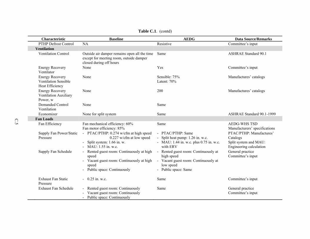
C.5
Table C.1. (contd)
Characteristic Baseline AEDG Data Source/Remarks PTHP Defrost Control NA Resistive Committee’s input Ventilation Ventilation Control Outside air damper remains open all the time
except for meeting room, outside damper closed during off hours
Same ASHRAE Standard 90.1
Energy Recovery Ventilator
None Yes Committee’s input
Energy Recovery Ventilation Sensible Heat Efficiency
None Sensible: 75% Latent: 70%
Manufactures’ catalogs
Energy Recovery Ventilation Auxiliary Power, w
None 200 Manufactures’ catalogs
Demanded Control Ventilation
None Same
Economizer None for split system Same ASHRAE Standard 90.1-1999 Fan Loads Fan Efficiency Fan mechanical efficiency: 60%
Fan motor efficiency: 85% Same AEDG-WHS TSD
Manufacturers’ specifications Supply Fan Power/Static
Pressure - PTAC/PTHP: 0.274 w/cfm at high speed
0.227 w/cfm at low speed - Split system: 1.66 in. w. - MAU: 1.55 in. w.c.
- PTAC/PTHP: Same - Split heat pump: 1.26 in. w.c. - MAU: 1.44 in. w.c. plus 0.75 in. w.c.
with ERV
PTAC/PTHP: Manufactures’ Catalogs Split system and MAU: Engineering calculation
Supply Fan Schedule - Rented guest room: Continuously at high speed
- Vacant guest room: Continuously at high speed
- Public space: Continuously
- Rented guest room: Continuously at high speed
- Vacant guest room: Continuously at low speed
- Public space: Same
General practice Committee’s input
Exhaust Fan Static Pressure
- 0.25 in. w.c. Same Committee’s input
Exhaust Fan Schedule - Rented guest room: Continuously - Vacant guest room: Continuously - Public space: Continuously
Same General practice Committee’s input
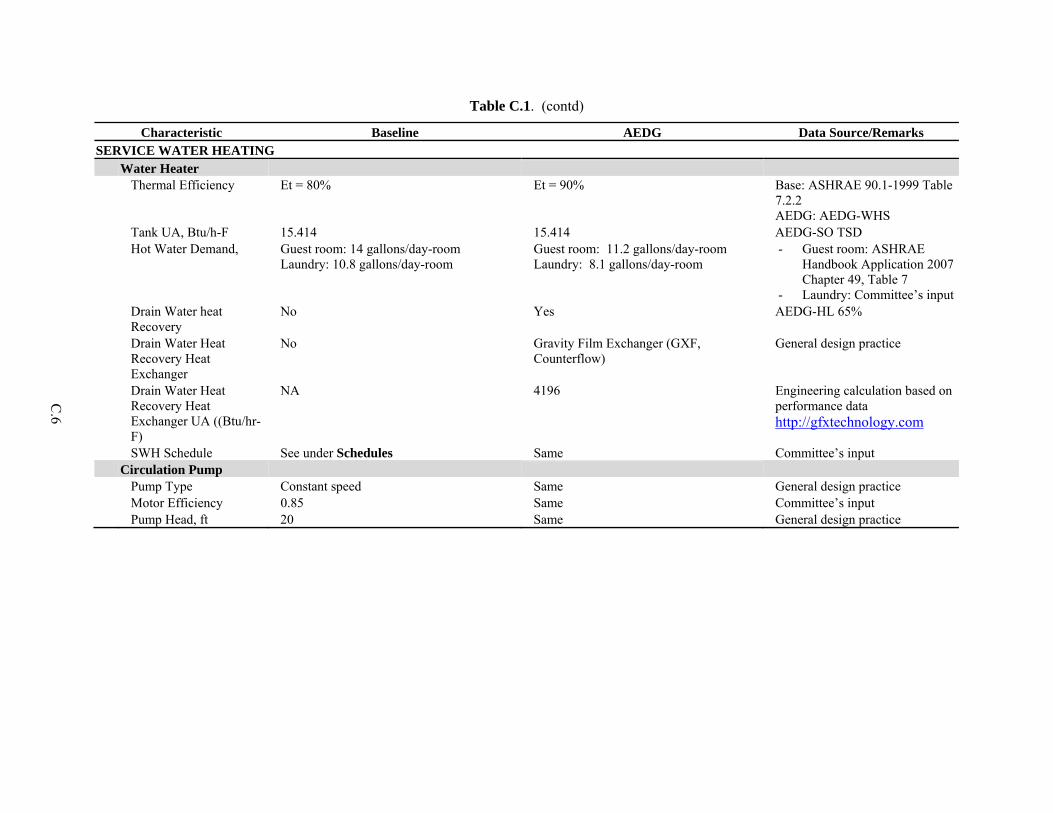
C.6
Table C.1. (contd)
Characteristic Baseline AEDG Data Source/Remarks SERVICE WATER HEATING Water Heater Thermal Efficiency Et = 80% Et = 90% Base: ASHRAE 90.1-1999 Table
7.2.2 AEDG: AEDG-WHS
Tank UA, Btu/h-F 15.414 15.414 AEDG-SO TSD Hot Water Demand, Guest room: 14 gallons/day-room
Laundry: 10.8 gallons/day-room Guest room: 11.2 gallons/day-room Laundry: 8.1 gallons/day-room
- Guest room: ASHRAE Handbook Application 2007 Chapter 49, Table 7
- Laundry: Committee’s input Drain Water heat
Recovery No Yes AEDG-HL 65%
Drain Water Heat Recovery Heat Exchanger
No Gravity Film Exchanger (GXF, Counterflow)
General design practice
Drain Water Heat Recovery Heat Exchanger UA ((Btu/hr-F)
NA 4196 Engineering calculation based on performance data http://gfxtechnology.com
SWH Schedule See under Schedules Same Committee’s input Circulation Pump Pump Type Constant speed Same General design practice Motor Efficiency 0.85 Same Committee’s input Pump Head, ft 20 Same General design practice
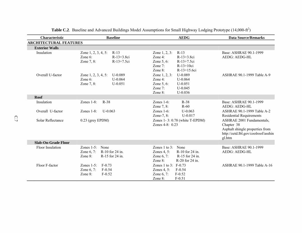
C.7
Table C.2. Baseline and Advanced Buildings Model Assumptions for Small Highway Lodging Prototype (14,000-ft2)
Characteristic Baseline AEDG Data Source/Remarks ARCHITECTURAL FEATURES Exterior Walls Insulation Zone 1, 2, 3, 4, 5: R-13
Zone 6: R-13+3.8ci Zone 7, 8: R-13+7.5ci
Zone 1, 2, 3: R-13 Zone 4: R-13+3.8ci Zone 5, 6: R-13+7.5ci Zone 7: R-13+10ci Zone 8: R-13+15.6ci
Base: ASHRAE 90.1-1999 AEDG: AEDG-HL
Overall U-factor Zone 1, 2, 3, 4, 5: U-0.089 Zone 6: U-0.064 Zone 7, 8: U-0.051
Zone 1, 2, 3: U-0.089 Zone 4: U-0.064 Zone 5, 6: U-0.051 Zone 7: U-0.045 Zone 8: U-0.036
ASHRAE 90.1-1999 Table A-9
Roof Insulation Zones 1-8: R-38 Zones 1-6: R-38
Zone 7, 8: R-60 Base: ASHRAE 90.1-1999 AEDG: AEDG-HL
Overall U-factor Zones 1-8: U-0.063 Zones 1-6: U-0.063 Zone-7, 8: U-0.017
ASHRAE 90.1-1999 Table A-2 Residential Requirements
Solar Reflectance 0.23 (grey EPDM) Zones 1- 3: 0.78 (white T-EPDM) Zones 4-8: 0.23
ASHRAE 2001 Fundamentals, Chapter 38 Asphalt shingle properties from http://eetd.lbl.gov/coolroof/asshingl.htm
Slab-On-Grade Floor Floor Insulation Zones 1-5: None
Zone 6, 7: R-10 for 24 in. Zone 8: R-15 for 24 in.
Zones 1 to 3: None Zones 4, 5: R-10 for 24 in. Zone 6, 7: R-15 for 24 in. Zone 8: R-20 for 24 in.
Base: ASHRAE 90.1-1999 AEDG: AEDG-HL
Floor F-factor Zones 1-5: F-0.73 Zone 6, 7: F-0.54 Zone 8: F-0.52
Zones 1 to 3: F-0.73 Zones 4, 5: F-0.54 Zone 6, 7: F-0.52 Zone 8: F-0.51
ASHRAE 90.1-1999 Table A-16
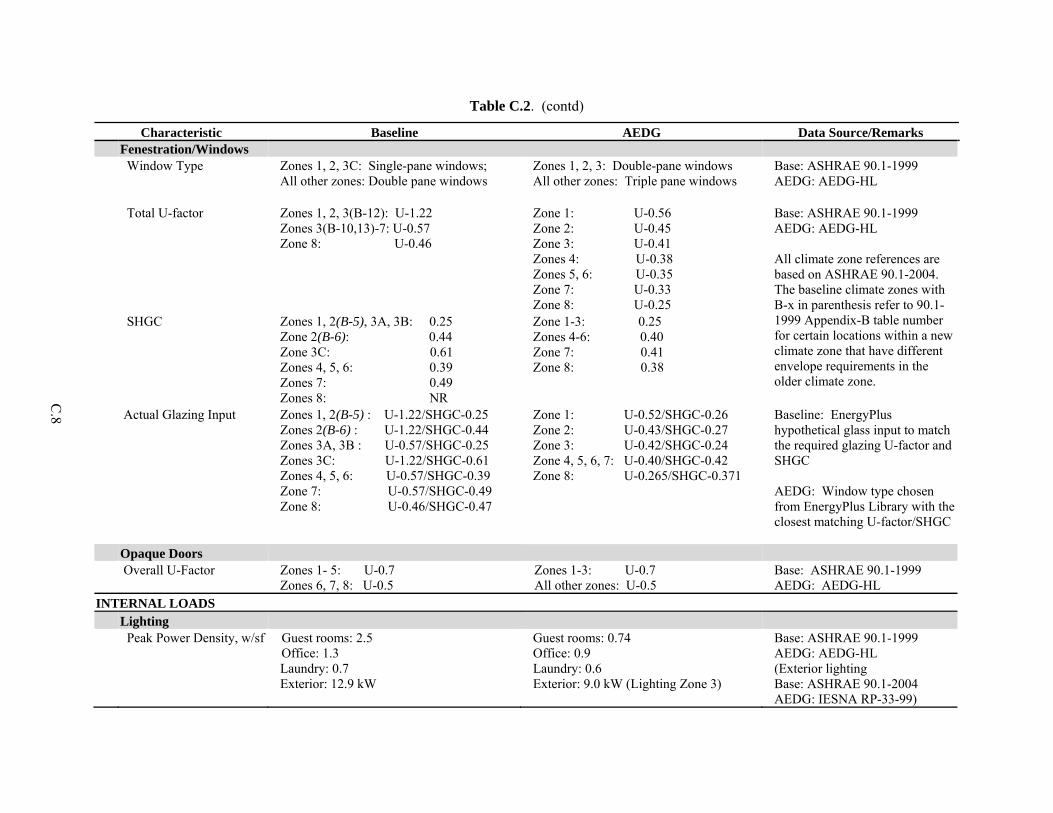
C.8
Table C.2. (contd)
Characteristic Baseline AEDG Data Source/Remarks Fenestration/Windows Window Type Zones 1, 2, 3C: Single-pane windows;
All other zones: Double pane windows Zones 1, 2, 3: Double-pane windows All other zones: Triple pane windows
Base: ASHRAE 90.1-1999 AEDG: AEDG-HL
Total U-factor Zones 1, 2, 3(B-12): U-1.22 Zones 3(B-10,13)-7: U-0.57 Zone 8: U-0.46
Zone 1: U-0.56 Zone 2: U-0.45 Zone 3: U-0.41 Zones 4: U-0.38 Zones 5, 6: U-0.35 Zone 7: U-0.33 Zone 8: U-0.25
Base: ASHRAE 90.1-1999 AEDG: AEDG-HL All climate zone references are based on ASHRAE 90.1-2004. The baseline climate zones with B-x in parenthesis refer to 90.1-1999 Appendix-B table number for certain locations within a new climate zone that have different envelope requirements in the older climate zone.
SHGC Zones 1, 2(B-5), 3A, 3B: 0.25 Zone 2(B-6): 0.44 Zone 3C: 0.61 Zones 4, 5, 6: 0.39 Zones 7: 0.49 Zones 8: NR
Zone 1-3: 0.25 Zones 4-6: 0.40 Zone 7: 0.41 Zone 8: 0.38
Actual Glazing Input Zones 1, 2(B-5) : U-1.22/SHGC-0.25 Zones 2(B-6) : U-1.22/SHGC-0.44 Zones 3A, 3B : U-0.57/SHGC-0.25 Zones 3C: U-1.22/SHGC-0.61 Zones 4, 5, 6: U-0.57/SHGC-0.39 Zone 7: U-0.57/SHGC-0.49 Zone 8: U-0.46/SHGC-0.47
Zone 1: U-0.52/SHGC-0.26 Zone 2: U-0.43/SHGC-0.27 Zone 3: U-0.42/SHGC-0.24 Zone 4, 5, 6, 7: U-0.40/SHGC-0.42 Zone 8: U-0.265/SHGC-0.371
Baseline: EnergyPlus hypothetical glass input to match the required glazing U-factor and SHGC AEDG: Window type chosen from EnergyPlus Library with the closest matching U-factor/SHGC
Opaque Doors Overall U-Factor Zones 1- 5: U-0.7
Zones 6, 7, 8: U-0.5 Zones 1-3: U-0.7 All other zones: U-0.5
Base: ASHRAE 90.1-1999 AEDG: AEDG-HL
INTERNAL LOADS Lighting Peak Power Density, w/sf Guest rooms: 2.5
Office: 1.3 Laundry: 0.7 Exterior: 12.9 kW
Guest rooms: 0.74 Office: 0.9 Laundry: 0.6 Exterior: 9.0 kW (Lighting Zone 3)
Base: ASHRAE 90.1-1999 AEDG: AEDG-HL (Exterior lighting Base: ASHRAE 90.1-2004 AEDG: IESNA RP-33-99)

C.9
Table C.2. (contd)
Characteristic Baseline AEDG Data Source/Remarks Lighting Schedule See under Schedules Same Committee’s input Occupancy Sensors No Yes Committee’s input Plug Load Peak Power Density, w/sf Guest rooms: 1.10
Laundry: Dryer gas - 1805 Btu/lb of water Dryer Electric – 0.75 kW/cycle Washer: 1.39 kWh/cycle (85G)
Guest rooms: 0.97 Laundry: Dryer gas/Electric – same as
base case Washer: 1.73 kWh/cycle (354G)
Engineering calculation Committee input – 60lb washer and 75 lb dryer, assuming 9 lbs of wash load per room
HVAC SYSTEM System Type Heating/ Cooling Type Package terminal air conditioner (PTAC)
with electric resistance (9 kBtu/h capacity); Package terminal heat pump (PTHP, 9 kBtu/h capacity);
Base: 2003 CBECS, NC3, Ducker Report AEDG: Committee’s input
HVAC Efficiency Cooing Efficiency PTAC: EER = 10.0
PTHP: EER = 11.5 Base: ASHRAE 90.1-1999
AEDG: PTHP: AHRI database Equipment efficiency remains the same in all climate zones.
Heating Efficiency PTAC: Et=100% PTHP: COP = 3.3 Base: ASHRAE 90.1-1999 AEDG: PTHP: AHRI database Equipment efficiency remains the same in all climate zones.
HVAC Control Cooling T-stat, °F - Rented guest room: 70
- Vacant guest room: 74 - Office/Laundry: 75
- Rented guest room: 70 during occupied period and 74 during unoccupied period (9am-4pm)
- Vacant guest room: Same - Office/Laundry: Same
General practice Committee’s input
Heating T-stat, °F - Occupied guest room: 70 - Vacant guest room: 66 - Office/Laundry: 70
- Rented guest room: 70 during occupied period and 66 during unoccupied period
- Vacant guest room: Same - Office/Laundry: Same
General practice Committee’s input
Design Supply Air, cfm 275 Same PTAC/PTHP: Manufacturers’ catalogs
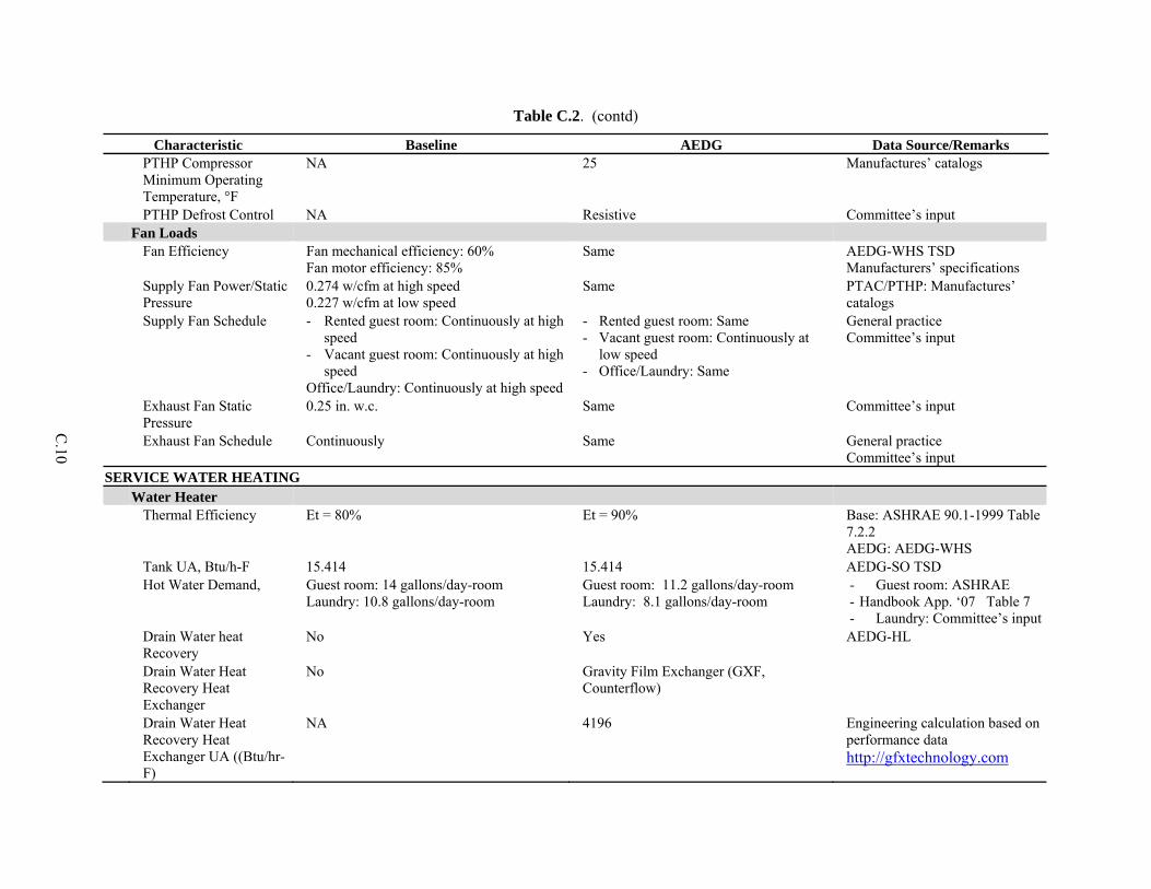
C.10
Table C.2. (contd)
Characteristic Baseline AEDG Data Source/Remarks PTHP Compressor
Minimum Operating Temperature, °F
NA 25 Manufactures’ catalogs
PTHP Defrost Control NA Resistive Committee’s input Fan Loads Fan Efficiency Fan mechanical efficiency: 60%
Fan motor efficiency: 85% Same AEDG-WHS TSD
Manufacturers’ specifications Supply Fan Power/Static
Pressure 0.274 w/cfm at high speed 0.227 w/cfm at low speed
Same PTAC/PTHP: Manufactures’ catalogs
Supply Fan Schedule - Rented guest room: Continuously at high speed
- Vacant guest room: Continuously at high speed
Office/Laundry: Continuously at high speed
- Rented guest room: Same - Vacant guest room: Continuously at
low speed - Office/Laundry: Same
General practice Committee’s input
Exhaust Fan Static Pressure
0.25 in. w.c. Same Committee’s input
Exhaust Fan Schedule Continuously Same General practice Committee’s input
SERVICE WATER HEATING Water Heater Thermal Efficiency Et = 80% Et = 90% Base: ASHRAE 90.1-1999 Table
7.2.2 AEDG: AEDG-WHS
Tank UA, Btu/h-F 15.414 15.414 AEDG-SO TSD Hot Water Demand, Guest room: 14 gallons/day-room
Laundry: 10.8 gallons/day-room Guest room: 11.2 gallons/day-room Laundry: 8.1 gallons/day-room
- Guest room: ASHRAE - Handbook App. ‘07 Table 7 - Laundry: Committee’s input
Drain Water heat Recovery
No Yes AEDG-HL
Drain Water Heat Recovery Heat Exchanger
No Gravity Film Exchanger (GXF, Counterflow)
Drain Water Heat Recovery Heat Exchanger UA ((Btu/hr-F)
NA 4196 Engineering calculation based on performance data http://gfxtechnology.com

C.11
Table C.2. (contd)
Characteristic Baseline AEDG Data Source/Remarks SWH Schedule See under Schedules Same Committee’s input Circulation Pump Pump Type Constant speed Same General design practice Motor Efficiency 0.85 Same Committee’s input Pump Head, ft 10 Same General design practice


Appendix D
Energy Savings Final Results by End Use


D.1
Appendix D
Energy Savings Final Results by End Use
Table D.1. Energy Savings Final Results by End Use for Small Highway Lodging (SHL) Prototype (ASHRAE 90.1-1999 as baseline)
Case Zone
Interior Lights
[MMBtu]
Exterior Lights
[MMBtu]Equipment [MMBtu]
Fans [MMBtu]
Pumps [MMBtu]
Cooling [MMBtu]
Heating [MMBtu]
SWH [MMBtu]
Total Energy
[MMBtu] EUI
[kBtu/SF]
Percentage of Energy Savings
SHL_Base_Miami 255 183 349 82 0 199 2 177 1,247 89.1SHL_Adva_Miami 84 114 250 77 0 148 1 112 786 56.2SHL_Base_Houston 255 182 349 82 0 154 51 212 1,284 91.7SHL_Adva_Houston 84 113 250 77 0 110 21 130 785 56.1SHL_Base_Phoenix 255 180 349 82 0 161 29 191 1,249 89.2SHL_Adva_Phoenix 84 113 250 77 0 124 11 124 783 55.9SHL_Base_Memphis 255 179 349 82 0 117 89 240 1,312 93.7SHL_Adva_Memphis 84 112 250 77 0 85 50 143 801 57.2SHL_Base_El_Paso 255 180 349 82 0 111 51 230 1,259 90.0SHL_Adva_El_Paso 84 113 250 77 0 78 29 143 774 55.3SHL_Base_San_Francis 255 179 349 82 0 46 55 269 1,236 88.3SHL_Adva_San_Francis 84 112 250 77 0 28 23 154 728 52.0SHL_Base_Albuquerque 255 179 349 82 0 82 111 268 1,327 94.8SHL_Adva_Albuquerqu 84 112 250 77 0 60 63 164 811 57.9SHL_Base_Baltimore 255 178 349 82 0 83 177 273 1,397 99.8SHL_Adva_Baltimore 84 111 250 77 0 61 103 164 851 60.8SHL_Base_Seattle 255 173 349 82 0 44 137 288 1,329 94.9SHL_Adva_Seattle 84 108 250 77 0 32 55 168 776 55.4SHL_Base_Boise 255 175 349 82 0 61 192 293 1,408 100.6SHL_Adva_Boise 84 109 250 77 0 47 105 175 848 60.5SHL_Base_Chicago 255 176 349 82 0 65 271 297 1,496 106.8SHL_Adva_Chicago 84 110 250 77 0 49 177 176 923 65.9SHL_Base_Burlington 255 174 349 82 0 50 330 318 1,559 111.3SHL_Adva_Burlington 84 109 250 77 0 36 266 186 1,008 72.0SHL_Base_Helena 255 174 349 82 0 47 263 321 1,492 106.6SHL_Adva_Helena 84 108 250 77 0 35 203 188 946 67.6SHL_Base_Duluth 255 174 349 82 0 36 432 351 1,680 120.0SHL_Adva_Duluth 84 109 250 77 0 26 370 202 1,117 79.8SHL_Base_Fairbanks 255 150 349 82 0 26 668 392 1,923 137.4SHL_Adva_Fairbanks 84 94 250 77 0 19 612 222 1,358 97.0
40%
38%
35%
37%
33%
8
37%
37%
39%
39%
39%
41%
39%
39%
42%4C
5A
5B
6A
6B
7
29%
1A
2B
2A
3A
3B
3C
4A
4B
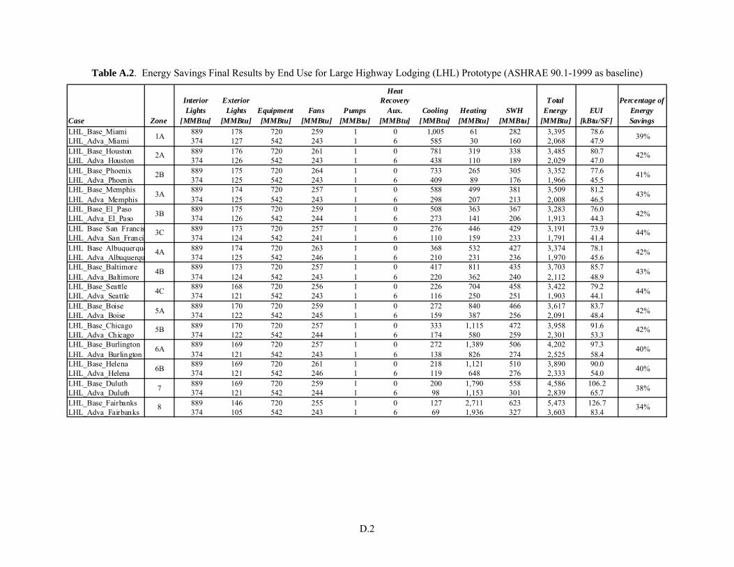
D.2
Table A.2. Energy Savings Final Results by End Use for Large Highway Lodging (LHL) Prototype (ASHRAE 90.1-1999 as baseline)
Case Zone
Interior Lights
[MMBtu]
Exterior Lights
[MMBtu]Equipment [MMBtu]
Fans [MMBtu]
Pumps [MMBtu]
Heat Recovery
Aux. [MMBtu]
Cooling [MMBtu]
Heating [MMBtu]
SWH [MMBtu]
Total Energy
[MMBtu] EUI
[kBtu/SF]
Percentage of Energy Savings
LHL_Base_Miami 889 178 720 259 1 0 1,005 61 282 3,395 78.6LHL_Adva_Miami 374 127 542 243 1 6 585 30 160 2,068 47.9LHL_Base_Houston 889 176 720 261 1 0 781 319 338 3,485 80.7LHL_Adva_Houston 374 126 542 243 1 6 438 110 189 2,029 47.0LHL_Base_Phoenix 889 175 720 264 1 0 733 265 305 3,352 77.6LHL_Adva_Phoenix 374 125 542 243 1 6 409 89 176 1,966 45.5LHL_Base_Memphis 889 174 720 257 1 0 588 499 381 3,509 81.2LHL_Adva_Memphis 374 125 542 243 1 6 298 207 213 2,008 46.5LHL_Base_El_Paso 889 175 720 259 1 0 508 363 367 3,283 76.0LHL_Adva_El_Paso 374 126 542 244 1 6 273 141 206 1,913 44.3LHL_Base_San_Francis 889 173 720 257 1 0 276 446 429 3,191 73.9LHL_Adva_San_Franci 374 124 542 241 1 6 110 159 233 1,791 41.4LHL_Base_Albuquerque 889 174 720 263 1 0 368 532 427 3,374 78.1LHL_Adva_Albuquerqu 374 125 542 246 1 6 210 231 236 1,970 45.6LHL_Base_Baltimore 889 173 720 257 1 0 417 811 435 3,703 85.7LHL_Adva_Baltimore 374 124 542 243 1 6 220 362 240 2,112 48.9LHL_Base_Seattle 889 168 720 256 1 0 226 704 458 3,422 79.2LHL_Adva_Seattle 374 121 542 243 1 6 116 250 251 1,903 44.1LHL_Base_Boise 889 170 720 259 1 0 272 840 466 3,617 83.7LHL_Adva_Boise 374 122 542 245 1 6 159 387 256 2,091 48.4LHL_Base_Chicago 889 170 720 257 1 0 333 1,115 472 3,958 91.6LHL_Adva_Chicago 374 122 542 244 1 6 174 580 259 2,301 53.3LHL_Base_Burlington 889 169 720 257 1 0 272 1,389 506 4,202 97.3LHL_Adva_Burlington 374 121 542 243 1 6 138 826 274 2,525 58.4LHL_Base_Helena 889 169 720 261 1 0 218 1,121 510 3,890 90.0LHL_Adva_Helena 374 121 542 246 1 6 119 648 276 2,333 54.0LHL_Base_Duluth 889 169 720 259 1 0 200 1,790 558 4,586 106.2LHL_Adva_Duluth 374 121 542 244 1 6 98 1,153 301 2,839 65.7LHL_Base_Fairbanks 889 146 720 255 1 0 127 2,711 623 5,473 126.7LHL_Adva_Fairbanks 374 105 542 243 1 6 69 1,936 327 3,603 83.4
42%
42%
40%
40%
38%
8
39%
41%
42%
43%
42%
44%
42%
43%
44%4C
5A
5B
6A
6B
7
34%
1A
2B
2A
3A
3B
3C
4A
4B
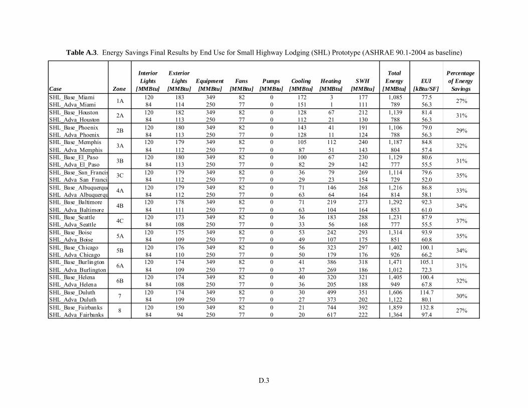
D.3
Table A.3. Energy Savings Final Results by End Use for Small Highway Lodging (SHL) Prototype (ASHRAE 90.1-2004 as baseline)
Case Zone
Interior Lights
[MMBtu]
Exterior Lights
[MMBtu]Equipment [MMBtu]
Fans [MMBtu]
Pumps [MMBtu]
Cooling [MMBtu]
Heating [MMBtu]
SWH [MMBtu]
Total Energy
[MMBtu] EUI
[kBtu/SF]
Percentage of Energy
SavingsSHL_Base_Miami 120 183 349 82 0 172 3 177 1,085 77.5SHL_Adva_Miami 84 114 250 77 0 151 1 111 789 56.3SHL_Base_Houston 120 182 349 82 0 128 67 212 1,139 81.4SHL_Adva_Houston 84 113 250 77 0 112 21 130 788 56.3SHL_Base_Phoenix 120 180 349 82 0 143 41 191 1,106 79.0SHL_Adva_Phoenix 84 113 250 77 0 128 11 124 788 56.3SHL_Base_Memphis 120 179 349 82 0 105 112 240 1,187 84.8SHL_Adva_Memphis 84 112 250 77 0 87 51 143 804 57.4SHL_Base_El_Paso 120 180 349 82 0 100 67 230 1,129 80.6SHL_Adva_El_Paso 84 113 250 77 0 82 29 142 777 55.5SHL_Base_San_Francis 120 179 349 82 0 36 79 269 1,114 79.6SHL_Adva_San_Francis 84 112 250 77 0 29 23 154 729 52.0SHL_Base_Albuquerque 120 179 349 82 0 71 146 268 1,216 86.8SHL_Adva_Albuquerqu 84 112 250 77 0 63 64 164 814 58.1SHL_Base_Baltimore 120 178 349 82 0 71 219 273 1,292 92.3SHL_Adva_Baltimore 84 111 250 77 0 63 104 164 853 61.0SHL_Base_Seattle 120 173 349 82 0 36 183 288 1,231 87.9SHL_Adva_Seattle 84 108 250 77 0 33 56 168 777 55.5SHL_Base_Boise 120 175 349 82 0 53 242 293 1,314 93.9SHL_Adva_Boise 84 109 250 77 0 49 107 175 851 60.8SHL_Base_Chicago 120 176 349 82 0 56 323 297 1,402 100.1SHL_Adva_Chicago 84 110 250 77 0 50 179 176 926 66.2SHL_Base_Burlington 120 174 349 82 0 41 386 318 1,471 105.1SHL_Adva_Burlington 84 109 250 77 0 37 269 186 1,012 72.3SHL_Base_Helena 120 174 349 82 0 40 320 321 1,405 100.4SHL_Adva_Helena 84 108 250 77 0 36 205 188 949 67.8SHL_Base_Duluth 120 174 349 82 0 30 499 351 1,606 114.7SHL_Adva_Duluth 84 109 250 77 0 27 373 202 1,122 80.1SHL_Base_Fairbanks 120 150 349 82 0 21 744 392 1,859 132.8SHL_Adva_Fairbanks 84 94 250 77 0 20 617 222 1,364 97.4
27%
1A
2B
2A
3A
3B
3C
4A
4B
4C
5A
5B
6A
6B
7
8
27%
29%
31%
32%
31%
35%
33%
34%
37%
35%
34%
31%
32%
30%

D.4
Table A.4. Energy Savings Final Results by End Use for Large Highway Lodging (LHL) Prototype (ASHRAE 90.1-2004 as baseline)
Case Zone
Interior Lights
[MMBtu]
Exterior Lights
[MMBtu]Equipment [MMBtu]
Fans [MMBtu]
Pumps [MMBtu]
Heat Recovery
Aux. [MMBtu]
Cooling [MMBtu]
Heating [MMBtu]
SWH [MMBtu]
Total Energy
[MMBtu] EUI
[kBtu/SF]
Percentage of Energy Savings
LHL_Base_Miami 491 178 720 258 1 0 907 75 282 2,912 67.4LHL_Adva_Miami 374 127 542 245 1 6 593 28 159 2,076 48.1LHL_Base_Houston 491 176 720 260 1 0 678 380 338 3,043 70.4LHL_Adva_Houston 374 126 542 245 1 6 443 108 189 2,033 47.1LHL_Base_Phoenix 491 175 720 264 1 0 656 294 305 2,906 67.3LHL_Adva_Phoenix 374 125 542 245 1 6 415 84 177 1,969 45.6LHL_Base_Memphis 491 174 720 255 1 0 518 576 381 3,116 72.1LHL_Adva_Memphis 374 125 542 244 1 6 302 204 213 2,011 46.5LHL_Base_El_Paso 491 175 720 258 1 0 442 394 367 2,847 65.9LHL_Adva_El_Paso 374 126 542 246 1 6 276 136 207 1,913 44.3LHL_Base_San_Francis 491 173 720 254 1 0 197 512 429 2,777 64.3LHL_Adva_San_Franci 374 124 542 242 1 6 111 156 233 1,790 41.4LHL_Base_Albuquerque 491 174 720 261 1 0 304 636 427 3,014 69.8LHL_Adva_Albuquerqu 374 125 542 248 1 6 214 229 236 1,975 45.7LHL_Base_Baltimore 491 173 720 256 1 0 352 975 435 3,403 78.8LHL_Adva_Baltimore 374 124 542 245 1 6 222 361 240 2,115 49.0LHL_Base_Seattle 491 168 720 254 1 0 165 866 458 3,123 72.3LHL_Adva_Seattle 374 121 542 244 1 6 117 248 251 1,903 44.1LHL_Base_Boise 491 170 720 257 1 0 219 1,020 466 3,344 77.4LHL_Adva_Boise 374 122 542 247 1 6 161 389 256 2,098 48.6LHL_Base_Chicago 491 170 720 256 1 0 277 1,337 472 3,725 86.2LHL_Adva_Chicago 374 122 542 245 1 6 177 581 259 2,306 53.4LHL_Base_Burlington 491 169 720 253 1 0 213 1,660 506 4,013 92.9LHL_Adva_Burlington 374 121 542 244 1 6 140 832 274 2,535 58.7LHL_Base_Helena 491 169 720 258 1 0 167 1,355 510 3,670 85.0LHL_Adva_Helena 374 121 542 247 1 6 121 655 277 2,344 54.3LHL_Base_Duluth 491 169 720 258 1 0 157 2,082 558 4,435 102.7LHL_Adva_Duluth 374 121 542 245 1 6 100 1,170 301 2,860 66.2LHL_Base_Fairbanks 491 146 720 253 1 0 93 3,064 623 5,390 124.8LHL_Adva_Fairbanks 374 105 542 244 1 6 69 1,955 328 3,623 83.9
33%
1A
2B
2A
3A
3B
3C
4A
4B
4C
5A
5B
6A
6B
7
8
29%
32%
33%
35%
33%
36%
34%
38%
39%
37%
38%
37%
36%
36%

Appendix E
Development of Envelope Criteria

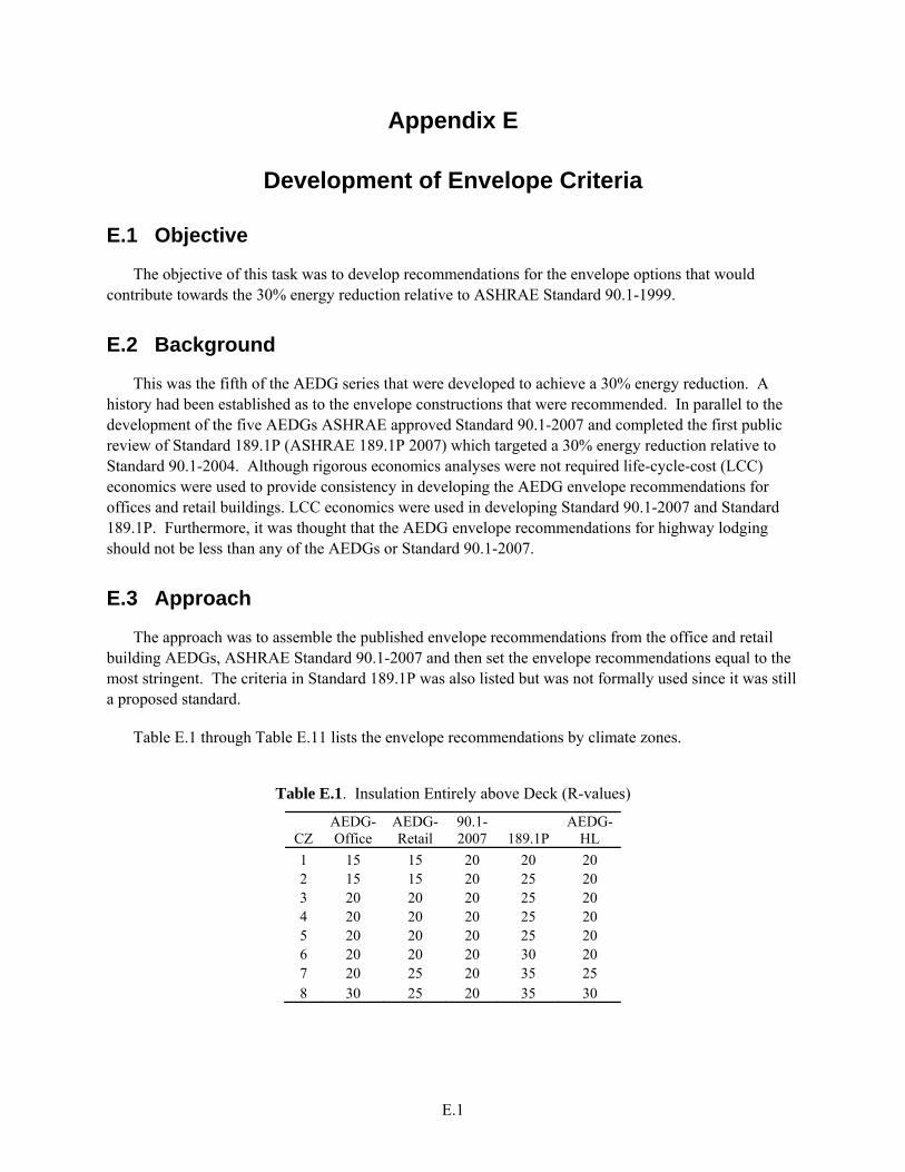
E.1
Appendix E
Development of Envelope Criteria
E.1 Objective
The objective of this task was to develop recommendations for the envelope options that would contribute towards the 30% energy reduction relative to ASHRAE Standard 90.1-1999.
E.2 Background
This was the fifth of the AEDG series that were developed to achieve a 30% energy reduction. A history had been established as to the envelope constructions that were recommended. In parallel to the development of the five AEDGs ASHRAE approved Standard 90.1-2007 and completed the first public review of Standard 189.1P (ASHRAE 189.1P 2007) which targeted a 30% energy reduction relative to Standard 90.1-2004. Although rigorous economics analyses were not required life-cycle-cost (LCC) economics were used to provide consistency in developing the AEDG envelope recommendations for offices and retail buildings. LCC economics were used in developing Standard 90.1-2007 and Standard 189.1P. Furthermore, it was thought that the AEDG envelope recommendations for highway lodging should not be less than any of the AEDGs or Standard 90.1-2007.
E.3 Approach
The approach was to assemble the published envelope recommendations from the office and retail building AEDGs, ASHRAE Standard 90.1-2007 and then set the envelope recommendations equal to the most stringent. The criteria in Standard 189.1P was also listed but was not formally used since it was still a proposed standard.
Table E.1 through Table E.11 lists the envelope recommendations by climate zones.
Table E.1. Insulation Entirely above Deck (R-values)
CZ AEDG-Office
AEDG-Retail
90.1-2007 189.1P
AEDG-HL
1 15 15 20 20 20 2 15 15 20 25 20 3 20 20 20 25 20 4 20 20 20 25 20 5 20 20 20 25 20 6 20 20 20 30 20 7 20 25 20 35 25 8 30 25 20 35 30
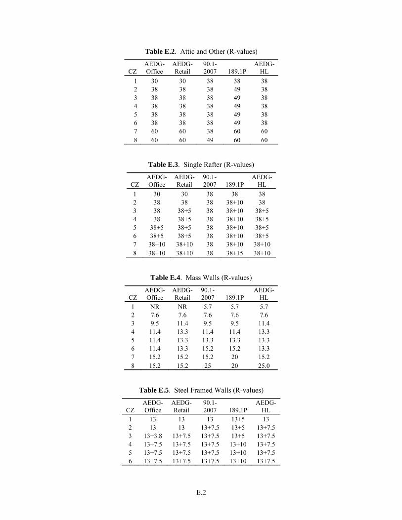
E.2
Table E.2. Attic and Other (R-values)
CZ AEDG-Office
AEDG-Retail
90.1-2007 189.1P
AEDG-HL
1 30 30 38 38 38 2 38 38 38 49 38 3 38 38 38 49 38 4 38 38 38 49 38 5 38 38 38 49 38 6 38 38 38 49 38 7 60 60 38 60 60 8 60 60 49 60 60
Table E.3. Single Rafter (R-values)
CZ AEDG-Office
AEDG-Retail
90.1-2007 189.1P
AEDG-HL
1 30 30 38 38 38 2 38 38 38 38+10 38 3 38 38+5 38 38+10 38+5 4 38 38+5 38 38+10 38+5 5 38+5 38+5 38 38+10 38+5 6 38+5 38+5 38 38+10 38+5 7 38+10 38+10 38 38+10 38+10 8 38+10 38+10 38 38+15 38+10
Table E.4. Mass Walls (R-values)
CZ AEDG-Office
AEDG-Retail
90.1-2007 189.1P
AEDG-HL
1 NR NR 5.7 5.7 5.7 2 7.6 7.6 7.6 7.6 7.6 3 9.5 11.4 9.5 9.5 11.4 4 11.4 13.3 11.4 11.4 13.3 5 11.4 13.3 13.3 13.3 13.3 6 11.4 13.3 15.2 15.2 13.3 7 15.2 15.2 15.2 20 15.2 8 15.2 15.2 25 20 25.0
Table E.5. Steel Framed Walls (R-values)
CZ AEDG-Office
AEDG-Retail
90.1-2007 189.1P
AEDG-HL
1 13 13 13 13+5 13 2 13 13 13+7.5 13+5 13+7.5 3 13+3.8 13+7.5 13+7.5 13+5 13+7.5 4 13+7.5 13+7.5 13+7.5 13+10 13+7.5 5 13+7.5 13+7.5 13+7.5 13+10 13+7.5 6 13+7.5 13+7.5 13+7.5 13+10 13+7.5

E.3
7 13+7.5 13+7.5 13+15.6 13+10 13+15.6 8 13+21.6 13+10 13+18.8 13+10 13+21.6
Table E.6. Wood Framed Walls (R-values)
CZ AEDG-Office
AEDG-Retail
90.1-2007 189.1P
AEDG-HL
1 13 13 13 13+3.8 13 2 13 13 13 13+3.8 13 3 13 13 13 13+3.8 13 4 13 13+3.8 13+3.8 13+3.8 13+3.8 5 13+3.8 13+7.5 13+7.5 13+7.5 13+7.5 6 13+3.8 13+7.5 13+7.5 13+10 13+7.5 7 13+7.5 13+7.5 13+7.5 13+10 13+10 8 13+10 13+7.5 13+15.6 13+10 13+15.6
Table E.7. Unheated Slabs (R-value, Depth – ft, R-value Below Slab)
CZ AEDG-Office
AEDG-Retail
90.1-2007 189.1P
AEDG-HL
1 NR NR NR NR NR 2 NR NR NR NR NR 3 NR NR NR NR NR 4 NR NR 10-24 10-24 10-24 5 NR 10-24 10-24 10-24 10-24 6 10-24 10-24 15-24 15-24 15-24 7 15-24 15-24 15-24 15-24+5 15-24 8 20-24 15-24 20-24 15-24+5 20-24
Table E.8. Swinging Doors (U-factor)
CZ AEDG-Office
AEDG-Retail
90.1-2007 189.1P
AEDG-HL
1 0.7 0.7 0.7 0.6 0.7 2 0.7 0.7 0.7 0.6 0.7 3 0.7 0.7 0.7 0.6 0.7 4 0.7 0.5 0.7 0.6 0.5 5 0.7 0.5 0.5 0.4 0.5 6 0.7 0.5 0.5 0.4 0.5 7 0.5 0.5 0.5 0.4 0.5 8 0.5 0.5 0.5 0.4 0.5
Table E.9. Non-Swinging Doors (U-factor)
CZ AEDG-Office
AEDG-Retail
90.1-2007 189.1P
AEDG-HL

E.4
1 1.45 1.45 1.45 0.5 1.45 2 1.45 1.45 0.5 0.5 0.5 3 1.45 0.5 0.5 0.5 0.5 4 0.5 0.5 0.5 0.4 0.5 5 0.5 0.5 0.5 0.4 0.5 6 0.5 0.5 0.5 0.4 0.5 7 0.5 0.5 0.5 0.4 0.5 8 0.5 0.5 0.5 0.4 0.5
The vertical fenestration U-factor for climate zone 8 was increased to match that of Standard 189.1P in order to achieve the 30% energy reduction.
Table E.10. Vertical Fenestration (U-factors)
CZ AEDG-Office
AEDG-Retail
90.1-2007 189.1P
AEDG-HL
1 0.56 0.69 1.20 1.20 0.56 2 0.45 0.49 0.75 0.75 0.45 3 0.45 0.41 0.65 0.45 0.41 4 0.42 0.38 0.40 0.30 0.38 5 0.42 0.38 0.35 0.25 0.35 6 0.42 0.38 0.35 0.25 0.35 7 0.33 0.38 0.35 0.25 0.33 8 0.33 0.38 0.35 0.25 0.25
The SHGC recommendations listed in Table E.11 were determined for a window-wall ratio (WWR) of 0.25. The vertical fenestration SHGC for climate zone 8 was decreased to match that of Standard 189.1P in order to achieve the 30% energy savings.
Table E.11. Vertical Fenestration (SHGC and Projection Factors)
all N All all
CZ AEDG-Office
AEDG-Office-N
AEDG-Retail
AEDG-Retail-N
90.1-2004
90.1-2004
90.1-2007 189.1P
AEDG-HL
AEDG-HL-PF
1 0.35 0.49 0.44 0.44 0.25 0.61 0.25 0.25 0.25 0.5 2 0.31 0.44 0.40 0.40 0.25 0.61 0.25 0.25 0.25 0.5 3 0.31 0.45 0.41 0.41 0.25 0.39 0.25 0.25 0.25 0.5 4 0.46 0.46 0.41 0.41 0.39 0.49 0.40 0.35 0.40 0.5 5 0.46 0.46 0.41 0.41 0.39 0.49 0.40 0.35 0.40 0.5 6 0.46 0.46 0.41 0.41 0.39 0.49 0.40 0.40 0.40 0.5 7 NR NR 0.41 0.41 0.49 0.61 NR 0.45 0.41 0.5 8 NR NR 0.41 0.41 NR NR NR 0.45 0.38 0.5

