technical service guide -...
TRANSCRIPT

GE Consumer & Industrial
Technical Service Guide May 2008
MONOGRAM ICEMAKER
ModelsZDIC150WZDIS150W
Pub. #31-####
G E Ap p l i a n c e s
G e n e r a l E l e c t r i c C o m p a n y
L o u i s v i l l e , K e n t u c k y 4 0 2 2 5

1
TABLE OF CONTENTSPageGENERALSpecifications -- AINSTALLATION INFORMATION ------------ B
Electrical Supply Requirements Water Supply and Drain Connections
Section 1 THEORY OF OPERATION Operating systems--------------------------------1-1
Electrical System-------------------------1-4Refrigeration System--------------------1-2Water System-----------------------------1-3
Operational Modes ------------------------1-5
Ice Making Cycle (freeze mode) –------------1-6Electrical System-------------------------1-7Refrigeration System--------------------1-8Water System-----------------------------1-9
Harvest Mode -------------------------------------1-10Electrical System-------------------------1-11Refrigeration System--------------------1-12Water System-----------------------------1-13
Clean Mode ----------------------------------------1-14Electrical System-------------------------1-15Refrigeration System--------------------1-16Water System-----------------------------1-17
Diagnostic Mode-----------------------------------1-18Diagnostic Chart ------------------------ 1-19Error Displays --------------------------- 1-20
Models With Internal Drain Pumps ---------- 1-21
Section 2 COMPONENT ACCESS
Component Locations ---------------------------2-1
Removing the Bin Thermistor, Cutter Grid, Evaporator Thermistor,& Water Distributor --------------------------- 2-2Removing The Bin Thermistor -------------– 2-3Removing Cutter Grid –------------------------ 2-4

2
Removing the evaporator thermister ------- 2-5Removing the water distributor -------------- 2-6
The Electronic Control Housing Components 2-7
Removing the electronic control board –--- 2-8Removing the dual transformer -------------- 2-9Removing the light switch assembly --------2-10Removing the Recirculation Pump & Water Level Sensor assm 2-11Removing the water level sensor ------------ 2-12Removing the reservoir drain pump --------- 2-13Removing the Condenser Fan Motor ------ 2-14Removing the Evaporator –------------------- 2-15Removing the Measured Fill Water Valve ---2-16Removing the Hot Gas Valve & Solenoid – 2-17Removing the Condenser ---------------------- 2-18Removing the Compressor ---------------------2-19Removing the Internal Drain Pump --------- 2-20Removing the Ice Maker Door & Gasket --- 2-21
SECTION 3 COMPONENT TESTING
Themistor Chart -----------------------------------–3-3Bin Thermistor –------------------------------------ 3-4Evaporator Thermistor --------------------------- 3-5Cutter Grid ------------------------------------------ 3-6Dual Transformer –-------------------------------- 3-7Water Recirculation Pump----------------------- 3-8Reservoir Drain Pump Water Level Sensor - 3-9Condenser Fan Motor –-------------------------- 3-10Water Level Sensor –----------------------------- 3-11Hot Gas Valve Solenoid --------------------------3-12Measured Fill Water Valve -----------------------3-13Compressor, Overload Protector, & Relay ---3-14
SECTION 4 DIAGNOSTICS & TROUBLESHOOTING
Water And Its Effect On Making Ice ------------ 4-1Effect on Ice Quality ------------------------------- 4-2Effect on Ice Maker -------------------------------- 4-3Recommendation ----------------------------------- 4-4Troubleshooting Chart ----------------------------- 4-5, 4-6, 4-7Diagnostic Flow Chart For Ice Maker Control Board --- 4-8Flush Mode --------------------------------------------- 4-9Freeze Mode ------------------------------------------- 4-10Harvest Mode ------------------------------------------ 4-11

3
Failure Mode ------------------------------------------- 4-12Clean Mode -------------------------------------------- 4-13WIRING DIAGRAM & STRIP CIRCUITS ------- 4-14Wiring Diagram --------------------------------------- 4-15Strip Circuits ------------------------------------------- 4-16Flush Mode --------------------------------------------- 4-17Freeze Mode ------------------------------------------- 4-18Harvest Mode ------------------------------------------ 4-19Clean Mode --------------------------------------------- 4-20Board connectors---------------------------------------4-21Cleaning The Evaporator Plate -------------------- 4-22
Reference Index
Clean Cycle 1-14, 4-13, 4-22Clean LED on Amber 1-14Clean LED on Red 1-14Control connector diagram 4-21Diagnostic Mode 1-18, 1-19Error Display 1-20Evaporator thermistor unplugged 1-11Harvest Mode 1-11Hung Slab 4-5, 4-10Ice Thickness setting 4-19Internal Drain Pump 1-21OFF LED 2 flash (blink) 1-20, 4-7, 4-12OFF LED 3 flash (blink) 1-20, 4-7, 4-11, 4-12Thermistor resistance chart 3-3Trouble shooting chart 4-5, 4-6, 4-7Twice ice (for stacking on cutter) 1-19Water and its effects on ice making 4-1Water fill volumes 1-9, 1-13Water sensor unplugged 1-11
SECTION ASPECIFICATIONS
4
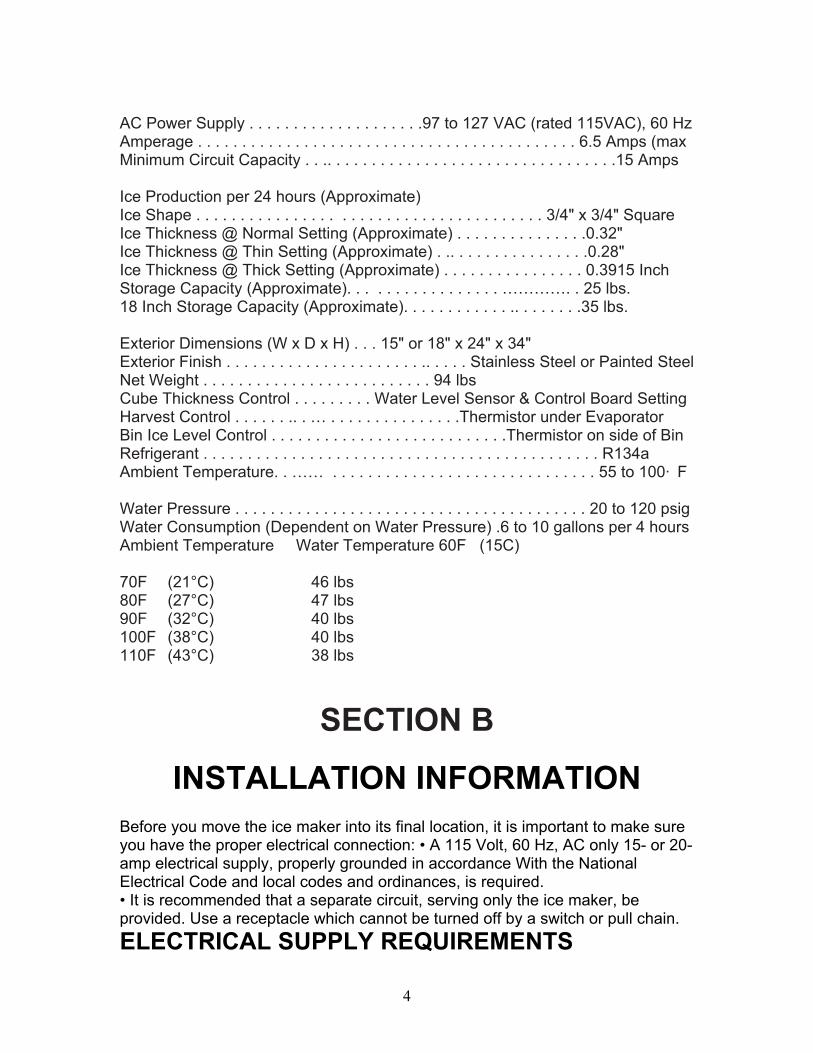
AC Power Supply . . . . . . . . . . . . . . . . . . . .97 to 127 VAC (rated 115VAC), 60 HzAmperage . . . . . . . . . . . . . . . . . . . . . . . . . . . . . . . . . . . . . . . . . . . 6.5 Amps (maxMinimum Circuit Capacity . . .. . . . . . . . . . . . . . . . . . . . . . . . . . . . . . . . .15 Amps
Ice Production per 24 hours (Approximate)Ice Shape . . . . . . . . . . . . . . . . . . . . . . . . . . . . . . . . . . . . . . . 3/4" x 3/4" SquareIce Thickness @ Normal Setting (Approximate) . . . . . . . . . . . . . . .0.32" Ice Thickness @ Thin Setting (Approximate) . .. . . . . . . . . . . . . . . .0.28" Ice Thickness @ Thick Setting (Approximate) . . . . . . . . . . . . . . . . 0.3915 Inch Storage Capacity (Approximate). . . . . . . . . . . . . . . . . …………. . 25 lbs. 18 Inch Storage Capacity (Approximate). . . . . . . . . . . . .. . . . . . . .35 lbs.
Exterior Dimensions (W x D x H) . . . 15" or 18" x 24" x 34" Exterior Finish . . . . . . . . . . . . . . . . . . . . . . .. . . . . Stainless Steel or Painted SteelNet Weight . . . . . . . . . . . . . . . . . . . . . . . . . . 94 lbsCube Thickness Control . . . . . . . . . Water Level Sensor & Control Board SettingHarvest Control . . . . . . .. . … . . . . . . . . . . . . . . .Thermistor under EvaporatorBin Ice Level Control . . . . . . . . . . . . . . . . . . . . . . . . . . .Thermistor on side of BinRefrigerant . . . . . . . . . . . . . . . . . . . . . . . . . . . . . . . . . . . . . . . . . . . . . R134aAmbient Temperature. . …… . . . . . . . . . . . . . . . . . . . . . . . . . . . . . . 55 to 100· F
Water Pressure . . . . . . . . . . . . . . . . . . . . . . . . . . . . . . . . . . . . . . . . 20 to 120 psigWater Consumption (Dependent on Water Pressure) .6 to 10 gallons per 4 hoursAmbient Temperature Water Temperature 60F (15C)
70F (21°C) 46 lbs 80F (27°C) 47 lbs 90F (32°C) 40 lbs 100F (38°C) 40 lbs 110F (43°C) 38 lbs
SECTION B
INSTALLATION INFORMATIONBefore you move the ice maker into its final location, it is important to make sure you have the proper electrical connection: • A 115 Volt, 60 Hz, AC only 15- or 20-amp electrical supply, properly grounded in accordance With the National Electrical Code and local codes and ordinances, is required.• It is recommended that a separate circuit, serving only the ice maker, be provided. Use a receptacle which cannot be turned off by a switch or pull chain.ELECTRICAL SUPPLY REQUIREMENTS

5
Electrical Shock HazardPlug into a grounded 3-prong outlet.Do not remove ground prong.Do not use an adapter.Do not use an extension cord.Failure to follow these instructions can result in death, fi re, or electrical shock.IMPORTANT: If this product is connected to a GFCI (Ground Fault Circuit interrupter) protected outlet, nuisance tripping of the power supply may occur, resulting in the loss of cooling. Ice quality may be affected. If nuisance tripping has occurred, and if the condition of the ice appears poor, dispose of it.Recommended Grounding MethodFor personal safety, this appliance must be grounded. This appliance is equippedwith a power supply cord having a 3-prong grounding plug. To minimize possible shock hazard, the cord must be plugged into a mating, 3- prong, grounding-typewall receptacle, grounded in accordance with the National Electrical Code and local codes and ordinances. If a mating wall receptacle is not available, it is the personal responsibility of the customer to have a properly grounded, 3-prong wall receptacle installed by a qualified electrician.
WARNINGWATER SUPPLY AND DRAIN CONNECTIONS8. Use 1/4" (6.35 mm) O.D. copper tubing for the cold water supply and:a) Measure from the connection at the back of the ice maker to the cold water pipe. b) Add an extra 36" (91.4 cm) to ensure that you have the proper length. Make sure both ends of the copper tubing are cut square.c) Slip a compression sleeve and compression nut over the ends of the copper tubing. d) Insert the end of tubing into the water shutoff outlet as far as it will go, and screw the compression nut onto the outlet. Tighten the compression nutwith an adjustable wrench, but do not over tighten it. 9. Place the free end of the copper tubing into a container or sink, and turn on the main water supply. Flush the tubing until water is clear, and then turn off the shutoff valve on the water pipe. NOTE: Always drain the water line before making the final connection to the inlet of the water valve to avoid a possible water valve malfunction. 10. Bend the copper tubing to meet the water line inlet, located on the back of the ice maker cabinet, as shown below.
CONNECTING THE WATER LINE1. Turn off the main water supply.2. Turn on the nearest faucet and allow it to run long enough to clear line of water.3. Find a 1/2 to 1-1/4 vertical cold water pipe near the icemaker.
6
NOTE: A horizontal pipe will work, but drill on the topside of the pipe, not the bottom. This will keep water away from the drill motor, and also keeps normal sediment from collecting in the valve.4. Using a grounded drill, a 1/4" hole in the cold water pipe you have selected.5. Fasten a shutoff valve to the cold water pipe with a pipe clamp. Make sure that the outlet end is firmly in the 1/4drilled hole, and that the washer is under the pipe clamp. IMPORTANT: Do not use a piercing-type, or a 3/16 saddle-type valve. These can reduce water flow and easily become clogged.6. Tighten the packing nut. 7. Tighten the pipe clamp screws carefully and evenly so that the washer makes a watertight seal. Do not over tighten the pipe clamp. If the water line is soft copper tubing, you could crush it.11. Thread the nut onto the coupling at the end of the copper tubing. Tighten the nut by hand. Then tighten it with a wrench two more turns. Do not over tighten.

7
CONNECTING THE DRAINGravity Drain SystemConnect the icemaker drain to your drain in accordance with all state and local codes and ordinances. If the icemaker is provided with a gravity drain system, use the following guidelines when installing the drain lines. This will avoid water from flowing back into the icemaker storage bin and potentially flowing onto the

8
floor, causing water damage. • Drain lines must have a minimum of 5/8" inside diameter.• Drain lines must have a 1" drop per 48" of run, or 1/4" drop per 12” and not have any low points where water can settle.• the floor drains must be large enough to accommodate drainage from all drains.• the ideal installation has a standpipe with a 1-1/2" PVC drain reducer installed directly below the outlet of the drain tube, as shown. You must maintain a 1" air gap between the drain hose and the standpipe.• It may be desirable to insulate the drain line up to the drain inlet.4. Center of drain should be 20” back from front of door. Drain Pump System (On Some Models)Connect the icemaker drain to your drain in accordance with the InternationalPlumbing Code and any local codes and ordinances.NOTE: If the drain hose becomes twisted and water cannot drain, the icemaker will not operate.Connecting the DrainAfter ensuring that the drain system is adequate, follow these steps to properly place the icemaker:1. Plug in icemaker or reconnect power.2. Style 1 - For gravity drain system; push the icemaker into position so that theicemaker drain tube is positioned over the PVC drain reducer. Style 2 - For drain pump system connect the drain pump outlet hose to the drain. See “Drain Pump System” earlier in this section.3. Recheck the icemaker to be sure that it is level.4. If it is required by your local sanitation code, seal the cabinet to the floor with an approved caulking compound after all water and electrical connections have been made.

9
SECTION 1
THEORY OF OPERATION1-1
OPERATING SYSTEMS
There are three operating systems in the icemaker:• Refrigeration System• Water System• Electrical System

10
1-2ELECTRICAL SYSTEMThe icemaker’s electrical system provides power for the refrigeration and water systems, and controls the operation of each component.

11
1-3REFRIGERATION SYSTEMThe refrigeration system in the icemaker is very similar to the system used in other refrigeration appliances. The refrigerant used in this unit is R134a.There are two very important additions to the refrigeration system in the icemaker: the Hot Gas Valve, and the Condenser Accumulator Tube. The components operate as follows: • Hot Gas Valve - Allows high-pressurerefrigerant gas to bypass the condenser and flow through the condenser accumulator tube.• Condenser Accumulator Tube - Hot gas pushes liquid refrigerant through the accumulator tube into the evaporator, helping to evenly heat the evaporator plate so that the ice slab releases quickly and evenly. (Diagram next page)

12

13
1-4WATER SYSTEMThe water system provides:• Fresh water for ice production• Water recirculation as ice is produced• Water removal after ice is produced
The water system circulates water on the evaporator to freeze into ice during the FREEZE CYCLE. During the HARVEST CYCLE, it drains away minerals and contaminates. During the CLEAN CYCLE, cleaning solution is circulated to clean the system of minerals and contaminates.The hardness of the water supplied to the icemaker will affect the quality of the ice that is produced. It may also affect the operation of the water system.A water softener, or polyphosphate feeder, will not cure all of the problems associated with hard water, but they can be used to reduce scale buildup in the icemaker. NOTE: Some poly phosphate feeders will cause a slime buildup in the water system when the water supply has a low mineral content. (Diagram next page)

14

15
1-5OPERATIONAL MODES
There are four main operational modes for the icemaker (more detailed operation is found in the flow chart on page:• Ice making cycle• Harvest• Clean• Service (Diagnostics)
1-6ICE MAKING CYCLE (Freeze Mode)There are three possible “Off” cycles for the icemaker. They occur when:
1. The bin is full of ice and the ON LED is illuminated (Idle mode).2. The OFF control switch has been held for three seconds. The ON LED will go out.3. Models with internal drain pump, power is interrupted by overfill.
1-7Electrical System (Freeze Mode)Line Voltage is supplied to the electrical control switches and the primary side of the step-down dual transformer. The dual transformer reduces 120 VAC to 8.75 VAC for the cutter grid and the bin light and 12 VAC for the drain andrecirculating pumps. The electronic control board directs 12 VAC to the water recirculating and reservoir drain pumps, and 120 VAC to the hot gas solenoid, condenser fan motor, and compressor. The measured fill water valve will always have 120 VAC on the BK and WH wires and 14 VDC on the OR/WH and BK/RD wires. An evaporator thermistor supplies temperature information to the electronic control to determine when to terminate the harvest cycle. 1-8Refrigeration System (Freeze Mode)The hot gas refrigerant, under high pressure, is forced through the condenser, where it changes into a liquid, and flows through the drier and capillary tube into the evaporator. Under low pressure in the evaporator, the liquid refrigerant absorbs heat from the water fl owing over the evaporator as the refrigerant evaporates into a gas. As a low pressure gas, the refrigerant flows back through the suction line of the heat exchanger, to the compressor. During the Freeze mode, some of the hot gas that is in the condenser accumulating tube, condenses to a liquid, and remains in the accumulating tube. During the later stages of the Freeze mode, as the ice slab forms on the evaporator freezing plate, some of the refrigerant passing through the evaporator will not evaporate into a gas, but will remain a liquid. This liquid refrigerant will settle in the accumulator, while the refrigerant vapor is sucked off through the suction tube at

16
the top of the accumulator. This accumulated liquid refrigerant will eventually be directed to the evaporator to quickly warm the evaporator plate during the Harvest mode.NOTE: It is very important that the accumulator is not tilted out of a horizontal position. If moved, it could cause compressor failure.1-9Water System (Freeze Mode)The water-recirculation pump moves the water from the reservoir pan up to the distributor, where it flows out over the evaporator freezing plate. Water that does not freeze on the evaporator plate runs off the front edge, and falls back into the reservoir, where it is recirculated back to the water distributor. As the ice slab forms, the minerals in the water are on the surface of the ice. The water flowing over the top of the ice slab washes these minerals back into the water reservoir pan. The water continues to recirculate until the water level in the reservoir drops to the bottom of the water level sensor. When the water level in the reservoir drops below the sensor, the control terminates the freeze mode and initiates the Harvest mode. The control signals the measured fill valve to fill to the selected water level setting.
The measured fill valve uses a flow meter to accurately fill to the correct volume. Thin Ice uses 32 ounces (954cc) Normal Ice 37 ounces (1106cc) and Thick Ice 42.5 ounces (1258cc). Note: 2 minute max fill approximately 42.5 ounces (1250 ml).

17

18
1-10HARVEST MODE1-11Electrical System (Harvest Mode)When the water level in the reservoir drops below the water level sensor it signals the electronic control to terminate power to the condenser fan, and thenthe water-recirculating pump. The reservoir drain pump is activated to fully drain the reservoir. Power is then supplied to the hot gas valve and a fill request is sent to the measured fill valve. The fill valve fills to the requested volume while the hotgas valve is energized for the balance of the harvest mode. If the evaporator thermistor is unplugged, the evaporator defaults to a timed 4-minute harvest. If the water level sensor is disconnected or open, the control defaults to 25 minutes of freeze time. The cleaning indicator LED feature will not function if the water level sensor is disconnected.1-12Refrigeration System (Harvest Mode)The hot gas valve opens, allowing high-pressure refrigerant gas to bypass the condenser, and flow through the condenser accumulating tube. The hot gas pushes the liquid refrigerant that has accumulated in the accumulator tube up into the evaporator. The hot liquid refrigerant evenly heats the evaporator plate so that the ice slab releases quickly and evenly. The ice slab, when released, slides off of the evaporator plate onto the cutter grid.
1-13Water System (Harvest Mode)The electronic control board sends a signal to the water valve. The signal tells the water valve how much water to be filled, allowing water to flow into the water reservoir pan. The water fill volume is determined by the ice thickness setting. Thin Ice uses 32 ounces (954cc) Normal Ice 37 ounces (1106cc) and Thick Ice 42.5 ounces (1258cc). Note: 2 minute max fill. As a result of the hot gas flow andthe ice sliding off the evaporator plate, the evaporator temperature begins to rise. When the evaporator thermistor reaches the set temperature (52°F), the unit switches to the Freeze mode. This cycling between Freeze and Harvest continues until the ice bin is full. The electronic control board operates the various components and systems in the icemaker for each of the Freeze and Harvest modes.
1-14

19
CLEAN MODEClean LED will come on
a) Amber after 50 hung slabs or 3500 freeze cycles b) Red after 70 hung slabs or 4000 freeze cycles.
With Clean LED on red and steady the unit must be cleaned to turn it off. When clean cycle is complete the Clean LED will be on green and Off LED on Red, hold Off button for 3 sec to turn Off before selecting On.
1-15Electrical System (Clean Mode)The electronic control board operates the various components and systems during the Clean Mode. For the order of the components cycled, see the operation mode 1-14. Clean cycle cannot be cancelled once started; it must complete a full cycle.
1-16Refrigeration System (Clean Mode)The compressor and hot gas valve operate to heat the evaporator. Note: Evaporator thermistor will cycle the Compressor off at 125F and on at 95F.
1-17Water System (Clean Mode)When the service control switch is in the “Clean” position, the water-recirculatingpump circulates the cleaning solution that has been added to the reservoir, up to the water distributor, across the evaporator, and back into the reservoir, where it is recirculated.
1-18DIAGNOSTIC MODE
1. Do not continue with the diagnosis of the ice maker if a fuse is blown, a circuit breaker is tripped, or if there is less than a 120 volt power supply at the wall outlet. 2. All units that have failed during the first few days of use should be checked for loose connections or miss-wiring.
Entering and Navigating — Manual Diagnostics• Turn the product on. Within 10 seconds of Power On, press and hold the On and the Clean buttons. Release both buttons when all user interface LEDs begin to flash. • Within 5 seconds of all LEDs flashing, push the Off button. This begins manual diagnostics. (flow chart 1-19)

20
• If no button is pressed within 5 seconds, the product goes into the automatic diagnostic mode used at the assembly plant. Each component is cycled for 5 seconds.• The Off button is used to advance through each step. • to exit manual diagnostics, press the On button

21
1-19Diagnostic Flow Chart
After pressing any button to enter manual diagnostics all LEDs will illuminate for5 seconds. The controls will then automatically move to the first component.
OFF button to advanceORDER COMPONENT ON LED OFF LED CLEAN LED1 Entry Into Test Mode On On On2 Bin Thermistor On Solid OK
2 Blinks Open4 Blinks Short
Off Off
3 Evaporator Thermistor Off Off On Solid OK2 Blinks – Ope4 Blinks – Sho
4a Water Valve 4 Minute Timeout Clean Button Press Will Advance to Step 6
Off On Solid Reservoir FullBlinking Reservoir Empty
On
4b Water Level Sensor Off On Solid Reservoir FullBlinking Reservoir Empty
On
5 Recirculation Pump On On On6 Reservoir Drain Pump On Off Off7 Compressor and Condenser Fan On Solid
While CoolingBlinking When Evap Thermistor Reaches 4.5 Deg. F; Full Frost Pattern Should be Visible
On
8 Compressor and Hot Gas Valve On Solid While Heating
On Solid While HeatingBlinking When Evap Thermistor Reaches 52 Deg. F
On Solid While
9 Twice Ice Off Off On Solid – No Blinking – 10 MBetween CyclePress Clean BCycle Between
10 Ice Thickness Off 2 Blinks – Thin4 Blinks – Normal6 Blinks – ThickPress Clean Button toCycle Between Settings
Off
1-20ERROR DISPLAYS (during normal operation)
These errors will occur at any time during normal operation if a thermistorfails.2 Blinks — OFF LED is blinking twice in repeating intervals – This signifies a bin thermistor failure. Check that the bin thermistor is plugged in to the control box.

22
Check that the bin thermistor is not open or shorted. Replace the thermistor if it is open or shorted.3 Blinks — OFF LED is blinking three times in repeating intervals – This signifies a harvest failure. Check that the evaporator thermistor is connected to the sealed system tubing. If the thermistor is plugged in, ensure that it is fully connected to the control box. (The icemaker will operate on a timed cycle if the evaporator thermistor is unplugged.) Check the resistance of the thermistor. If the thermistor checks good look for a hot gas failure, a sealed system leak or restriction.1-21MODELS WITH INTERNAL DRAIN PUMPS
The power cord on the internal drain pump is connected to a 120 VAC wall outlet. The icemaker is then connected to the 120 VAC outlet on the drain pump. If the drain pump fails, or if the drain becomes blocked, power is shut off to the 120 VAC outlet on the drain pump. When the unit is first plugged in, the drain pump will run for 20 seconds. The power can be disconnected and reconnected to verify that the pump is operating properly. Water from the icemaker reservoir, or melting ice from the bin, drains down the bin drain tube into the pump inlet, and then into the drain pump chamber. As the water level rises, it bridges the “full” contacts, and the pump starts to run. The pump discharges the water through the outlet and the check valve. When the “full” connection is removed, the pump runs for an additional 12 seconds to empty the tank. If the water level in the drain pump continues to rise, due to a slow or blocked drain, or a blocked vent hose, and touches the “overfill” contact, power will be turned off to the drain pump’s 120 VAC outlet, causing the icemaker to turn off.

23
SECTION 2
COMPONENT ACCESSThis section instructs you on how to service each component. The components and their locations are shown below.2-1COMPONENT LOCATIONS

24
2-2REMOVING THE BIN THERMISTOR, CUTTER GRID, EVAPORATOR THERMISTOR, & WATER DISTRIBUTOR1. Unplug ice maker or disconnect power.2. Open the icemaker door.3. Cover or remove the ice from the storage bin.4. Place a cloth in the drain hole to avoid hardware from falling inside.5. Remove the two hex-head screws from the cutter grid cover and remove the cover.
. 2-3To remove the bin thermistor:
a) Disconnect the bin thermistor connector from the bottom of the control housing.b) Pull the bin thermistor out of the retaining clamp and remove it.

25
2-4To remove the cutter grid:
a) Disconnect the cutter grid and bin thermistor connectors from the bottom of the control housing.b) Remove the two hex-head screws from both sides of the cutter grid. The longer screw and white spacer are on the right side.
c) Slide the cutter grid forward and out of the unit and place it on a work surface. Be careful not to scratch the icemaker liner.d) Remove the spacer from the right cutter grid bracket tab.
e) Unsnap the two ice guides from the cutter grid tabs. There should be a slight outward tilt after the guides are installed. Bend the metal tabs outward if necessary.
2-5To remove the evaporator thermistor:
a) Remove the cutter grid from the unit.b) Disconnect the evaporator thermistor connector from the bottom of the control housing.c) Remove the two hex-head mounting screws from the water trough and pull the trough from the unit.

26
d) Reach behind the accumulator, and unclip the evaporator thermistor
2-6To remove the water distributor:
a) Remove the cutter grid from the unit.b) Pull out on the left and right water distributor retainers, and remove the tabs from the slots in the evaporator. Pull the distributor forward andremove the water hose.
2-7REMOVING THE ELECTRONIC CONTROLHOUSING COMPONENTS1. Unplug ice maker or disconnect power.2. Open the icemaker door.3. Cover or remove the ice from the storage bin.4. Remove the cutter grid cover and the cutter grid.5. Disconnect the remaining two connectors (bin and evaporator thermister) from the bottom of the control housing.6. Remove the four hex-head screws from the control housing and lower the housing so that you can access the components.

27
NOTE: The control housing components consist of:• Electronic control board• Dual transformer• Light switch• Push-button switch assembly
2-8To remove the electronic control board:
a) Disconnect the six harness connectors from the board terminals.b) Remove the two mounting screws.
2-9To remove the dual transformer:
a) Disconnect the 6-pin wire connector from harness. b) Remove the two mounting screws from the transformer bracket. c) Disconnect the green ground wire from its terminal.
NOTE: Reconnect the green ground wire when installing new dual transformer.

28
NOTE: If the switch assembly or light switch is replaced, the replacement part and decorative overlay must be ordered using the model number of the icemaker. The service replacement switch is not supplied with a decorative overlay.
2-10To remove the light switch or push-button switch assembly:
a) Peel off the decorative overlay from the front of the control housing.
b) Disconnect the Molex plug from switch assembly. Press the back of switch assembly and push the switch assembly out of the housing.
2-11REMOVING THE WATER RECIRCULATION PUMP/ WATER LEVEL SENSOR ASSM.

29
1. Unplug ice maker or disconnect power.2. Open the icemaker door.3. Remove the ice from the storage bin.4. Unscrew the drain cap from the reservoir, drain the water, and replace the cap tightly.5. Place a cloth in the drain hole to avoid hardware from falling inside.6. Remove the hex-head screw from the water recirculation pump shield and remove the shield (see photo).7. Disconnect the water fill tube from the pump-mounting bracket.8. Disconnect the two wire recirculation and drain pump connectors from the harness block.9. Remove the two thumbscrews from the reservoir and remove the reservoir from the icemaker.10. Remove the recirculation pump outlet tube.11. Remove three hex-headed screws from the pump mounting bracket and remove pump/water level sensor assembly.
2-12To remove the water level sensor: note: sensor only available as part of recirculation pump assembly
a) Disconnect the water level sensor electrical connection.b) Remove the retaining clips, if present.c) Pull the sensor up and out of the bracket.
2-13REMOVING THE RESERVOIR DRAIN PUMP

30
1. Unplug ice maker or disconnect power.2. Open the icemaker door.3. Unscrew the drain cap from the reservoir, drain the water, and replace the cap tightly.4. Remove the recirculating pump cover hex-head screw.5. To remove reservoir drain pump:
a) Disconnect the reservoir drain pump electrical connection.b) Remove the pump retaining screw and bracket.c) Rotate the pump 1/4 turn and pull it down and out of reservoir.
2-14REMOVING THE CONDENSER FAN MOTOR
1. Unplug ice maker or disconnect power.2. Open the icemaker door.3. Remove the ice from the storage bin.4. Disconnect the water and drain lines from the icemaker and remove the unit from its installation.5. Remove the four hex-head screws from the front panel and remove the panel.
6. Remove the two 5/16” screws from the front of the cabinet.7. Remove two hex-head screws from the measured fill water valve bracket.8. Allow the valve to drop down out of the way

31
NOTE: If the unit you are servicing is equipped with an internal drain pump, perform steps 9 and 10. If the unit does not have an internal pump, skip thosesteps, and proceed to step 11. 9. From the back of the unit, remove the four screws from the unit compartment cover and remove the cover.
10. Disconnect the inlet tube and the vent tube from the internal drain pump.
11. Tilt the front of the cabinet up until you can access the two side screws on theCondenser fan motor shroud, and secure the cabinet so that it cannot tip forward or backward.

32
Tubing12. Disconnect the wire connector from the condenser fan motor.13. Remove the four screws (two bottom and two side) from the condenser fan motor shroud. Slide the shroud assembly back towards the compressor, and then lift and remove the assembly from the unit.
14. Remove condenser fan motor blade by pulling the fan blade straight off the shaft. NOTE: Make sure when reinstalling the fan blade that the blade is seated completely on motor shaft.15. Remove the two hex-head screws from the condenser fan motor and remove it from the shroud.
2-15

33
REMOVING THE EVAPORATOR
1. Unplug ice maker or disconnect power.2. Remove the top door screw from the icemaker door, and pull the door off the bottom hinge. Note: (if unit has handle attached to top of door it must be removed to access hinge screw)3. Remove the ice from the storage bin.4. Remove the cutter grid and the evaporator thermistor from the unit.5. Disconnect the bin thermistor connector from the bottom of the control housing.6. Remove the two 5/16” hex-head screws from the top hinge and remove the hinge.7. Remove the two front and two rear screws from the cabinet top.8. Lift the cabinet top and position it forward on top of the unit.9. Remove the six screws from the counterbalance plate and remove the plate from the rear of the unit. 10. From the rear of the unit, remove the six hex-head screws from the channel cover and remove the cover.11. Remove the four screws from the unit compartment cover and remove the cover.12. Cut the tie wrap from around the tubing and wire harness inside the channel.13. Remove the two screws from the reservoir water trough and remove the trough.14. Remove the hex-head screw from the water recirculation pump shield and remove the shield.15. Remove the water fill tube from the notch in the water recirculation pump bracket, and pull the free end of the water line up, out of the unit.16. Pull out on the left and right water distributor retainers and remove the tabs from the slots in the evaporator, disconnect it from the hose, and remove it.17. Remove the four screws from the evaporator and then carefully lift the evaporator just high enough to remove the two right spacers.18. Lift the cabinet top off the unit and stand it on the floor near the rear of the unit.19. Lift the evaporator and its connecting tubing high enough from the unit to access the tubing underneath.20. Access the sealed system and discharge the refrigerant into an approved recovery system.21. Unbraze (or cut) the evaporator from the tubing at the following locations:• Suction line at the compressor.• Hot gas line at the hot gas valve.• Cut capillary tube at the drier filter.
REASSEMBLY NOTES:
34
When installing the new evaporator, use a generous amount of thermal heat trap paste between the hot gas valve, and the evaporator-tubing joint to protect the hot gas valve when brazing. • be sure to reinstall the Permagum in the liner channel of the cabinet around the wire sheath and tubing, so that there are no air leaks after the cabinet top is installed.
2-16REMOVING THE MEASURED FILL WATER VALVE1. Unplug ice maker or disconnect power.2. Turn water supply off to ice maker.3. Open the icemaker door.4. Remove the four hex-head screws from the front panel and remove the panel.5. Remove the two hex-head screws from the measured fill water valve bracket.6. Place a pan or towel under the valve to catch water.7. Disconnect the water inlet and outlets tubing from the quick disconnect fittings on the measured fill water valve.8. Disconnect the two electrical connectors from the valve.
2-17REMOVING THE HOT GAS VALVE & SOLENOID1. Unplug ice maker or disconnect power. 2. Tip the front of the cabinet back and prop it up 3. To remove the hot gas valve solenoid
a) Disconnect the 2-wire connector from the solenoid terminals. b) Remove the 7mm hex-head screw from the solenoid and lift the solenoid off the hot gas valve.
4. To remove the hot gas valve:a) Remove the solenoid from the hot gas valve (see step 3 for the procedure).b) Access the sealed system and discharge the refrigerant into an approved recovery system.c) Unbraze the hot gas valve from the tubing.
REASSEMBLY NOTE: When installing the new hot gas valve, use a generous amount of thermal heat trap paste between the valve and tubing joints to protect the valve when brazing.
2-18REMOVING THE CONDENSER1. Unplug ice maker or disconnect power.2. Tip the front of the cabinet back and prop it up

35
3. Remove the four condenser fan motor screws from the fan motor shroud and pull the motor assembly back away from the condenser as far as possible, but do not remove it 4. Remove the two mounting screws from the condenser bracket flanges.5. Access the sealed system and discharge the refrigerant into an approved recovery system.6. Unbraze the two condenser joints from the tubing.
2-19REMOVING THE COMPRESSOR1. Unplug ice maker or disconnect power.2. Open the icemaker door.3. Remove the ice from the storage bin.4. Disconnect the water and drain lines from the icemaker and remove the unit from its installation.5. At the rear of the unit, remove the four screws from the unit compartment cover and remove the cover.6. Remove the terminal cover using a standard screwdriver. Insert the screwdriver into the cover slot, and press down to unsnap and remove it.7. Remove the wires from the ground terminal, the overload protector terminal, and the relay terminal.8. Pull the overload protector and relay from the compressor pins.9. Pull the two clips off the rear studs of the compressor. 10. Tip the front of the cabinet back and prop it up.11. Access the sealed system and discharge the refrigerant into an approved recovery system.12. Cut the suction and discharge lines from the compressor.13. Cut the drier filter from the system (do not use a torch to remove the drier filter).14. Unbraze the compressor suction and discharge joints from the tubing. 15. Pull the clips off the compressor-mounting studs.16. Lift the compressor off the four mounting studs and remove it from the unit. Remove the four metal spacers and rubber isolators from the compressor stud locations.Perform the following steps after installing the new compressor.1. Install the overload protector and relay on the compressor pins.2. Connect the wires to the ground terminal the overload protector terminal, and the relay terminal.
2-20REMOVING THE INTERNAL DRAIN PUMP1. Unplug ice maker or disconnect power.2. Remove the ice from the storage bin.

36
3. Disconnect the water and drain lines from the icemaker and remove the unit from its installation.4. At the rear of the unit, remove the four screws from the unit compartment cover and remove the cover.5. Loosen the clamps and pull the ends of the three water lines from the internal drain pump.6. Disconnect the power cord plug from the internal drain pump.7. Remove the two mounting screws from the internal drain pump.8. Remove the internal drain pump from the unit.
2-21REMOVING THE ICE MAKER DOOR & GASKET1. To remove the door, remove the top door screw from the icemaker door, and pull the door off the bottom hinge. Note: (if unit has handle attached to top of door it must be removed to access hinge screw)2. To remove the door gasket:
a) Open the icemaker door.b) Pull the gasket out of the door track. NOTE: Be sure to check the new
gasket for a proper seal after you install it.
SECTION 3
COMPONENT TESTING
3-1Before testing any of the components, perform the following checks: • Control failure can be the result of corrosion on connectors. Therefore, disconnectingand reconnecting wires will be necessary throughout test procedures.• All tests/checks should be made with a VOM or DVM having a sensitivity of 20,000 ohms per- volt DC, or greater. • Check all connections before replacing components, looking for broken or loose wires, failed terminals, or wires not pressed into connectors far enough.• Resistance checks must be made with power cord unplugged from outlet, and with wiring harness or connectors disconnected.
3-2BIN AND EVAPORATOR THERMISTORS

37
For the most accurate measurement, immerse the thermistor in ice water for 5 minutes and then use the 32°F/0°C reading in the chart.
3-3
Deg F Deg C Thermistor resistance0 -18 81,715 - 99,874
10 -12 59,422 - 72,62732 0 30,266 - 36,99250 10 18,219 - 22,26770 21 10,280 - 12,56490 32 6,387 - 7,807
3-4BIN THERMISTOR:
Refer to 2-3 for the procedure for accessing the bin thermistor.
3-5EVAPORATOR THERMISTOR:
Refer to 2-5 for the procedure for accessing the evaporator thermistor.
3-6CUTTER GRID
Refer to 2-4 for the procedure for accessing the cutter grid. The ohmmeter should indicate 4 to 5 ohms
3-7DUAL TRANSFORMER
Refer to 2-9 for the procedure for accessing the dual transformer. 1) Primary black and white leads of the dual transformer. The ohmmeter should indicate between 3.5 and 4.5 ohms.2) Secondary yellow and yellow leads of the dual transformer. The ohmmeter should indicate between 0.11 and 0.14 ohms.3) Secondary red and red leads of the dual transformer. The ohmmeter should indicate between 0.14 and 0.18 ohms.
3-8WATER RECIRCULATION PUMP

38
Refer to 2-11 for the procedure for accessing the water recirculation pump. The ohmmeter should indicate approximately 3.6 ohms.
3-9RESERVOIR DRAIN PUMP
Refer to 2-13 for the procedure for accessing the reservoir drain pump. The ohmmeter should indicate approximately 3.6 ohms.
3-10CONDENSER FAN MOTORRefer to 2-14 for the procedure for accessing the condenser fan motor.1. Run the diagnostic tests (see 1-19) and check for the proper operation of the condenser fan motor.NOTE During operation, 120 volts in will be present at the condenser fan motor electrical connector.
3-11WATER LEVEL SENSOR CONDENSER FAN MOTOR
Refer to 2-11 for the procedure for accessing the water level sensor.1. Run the diagnostic tests (see 1-19) and check for the proper operation of the water level sensor, in step 4a & 4b.2. With the water level sensor immersed in water the Service LED should stay on solid.3. With the water level sensor out of the water the Service LED should blink.
3-12HOT GAS VALVE SOLENOID
Refer to 2-17 for the procedure for accessing the hot gas valve solenoid. The ohmmeter should indicate between 365 and 390 ohms.
3-13MEASURED FILL WATER VALVE
Refer to 2-16 for the procedure for accessing the measured fill water valve. The ohmmeter should indicate between 240 and 280 ohms. Refer to 1-19 for diagnostic mode.

39
3-14COMPRESSOR, OVERLOAD PROTECTOR, & RELAY
Refer to 2-19 for the procedure for accessing the compressor.To test the compressor windings:
1) Touch one of the ohmmeter test leads to the Common (C) pin, and the other lead to the Start (S) pin. The ohmmeter should indicate between 8 and 11 ohms.2) Touch one of the ohmmeter test leads to the Common (C) pin, and the other lead to the Run (M) pin. The ohmmeter should indicate between 2 and 3 ohms.
To test the relay:1) Position the relay with the coil facing down, as shown below.2) Insert the tip on one of the ohmmeter test leads into the Run (M) pin socket, and touch the other ohmmeter lead to the spade terminal. The meter should indicate a closed circuit (0 ohms).3) Move the tip of the ohmmeter test lead from the spade terminal into the Start (S) pin socket. Leave the other ohmmeter lead at the Run (M) location. The meter should indicate an open circuit (infinite).4) Turn the relay over so that the coil faces up, as shown below.5) With the tip of the ohmmeter test leads at the Start (S) and Run (M) pin sockets, the meter should indicate a closed circuit (0 ohms).
SECTION 4DIAGNOSTICS &
TROUBLESHOOTING
4-1WATER AND ITS EFFECT ON MAKING ICEQuality ice is defined as solid, clear, and free of taste or odor. All icemakers can provide this type of ice only if the water used to produce the ice is pure, and free of mineral contamination. The following charts show some of the problems that can affect ice production.
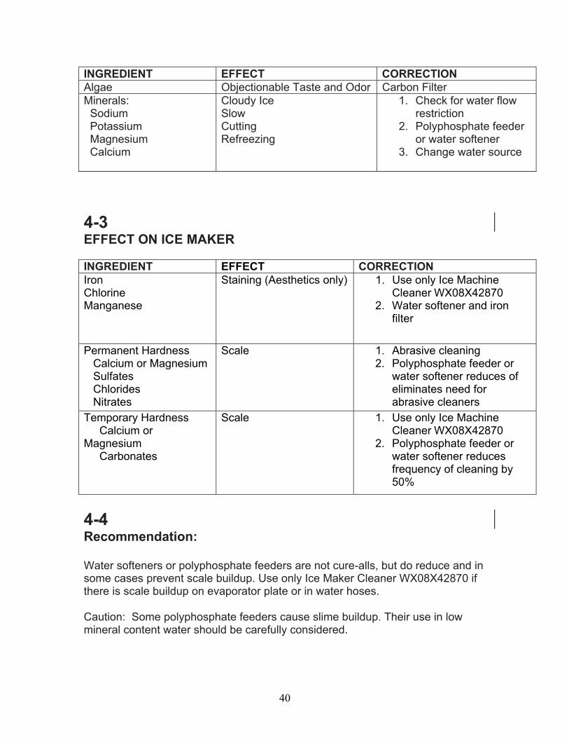
4-2EFFECT ON ICE QUALITY
40
INGREDIENT EFFECT CORRECTIONAlgae Objectionable Taste and Odor Carbon FilterMinerals: Sodium Potassium Magnesium Calcium
Cloudy IceSlowCuttingRefreezing
1. Check for water flow restriction
2. Polyphosphate feeder or water softener
3. Change water source
4-3EFFECT ON ICE MAKER
INGREDIENT EFFECT CORRECTIONIronChlorineManganese
Staining (Aesthetics only) 1. Use only Ice Machine Cleaner WX08X42870
2. Water softener and iron filter
Permanent Hardness Calcium or Magnesium Sulfates Chlorides Nitrates
Scale 1. Abrasive cleaning2. Polyphosphate feeder or
water softener reduces of eliminates need for abrasive cleaners
Temporary Hardness Calcium or Magnesium Carbonates
Scale 1. Use only Ice Machine Cleaner WX08X42870
2. Polyphosphate feeder or water softener reducesfrequency of cleaning by 50%
4-4Recommendation:
Water softeners or polyphosphate feeders are not cure-alls, but do reduce and in some cases prevent scale buildup. Use only Ice Maker Cleaner WX08X42870 if there is scale buildup on evaporator plate or in water hoses.
Caution: Some polyphosphate feeders cause slime buildup. Their use in low mineral content water should be carefully considered.

41
Note: Reverse Osmosis filters are not recommended with this unit. These filters can limit the water flow to the unit and limit its capacity to produce sufficient ice.
42
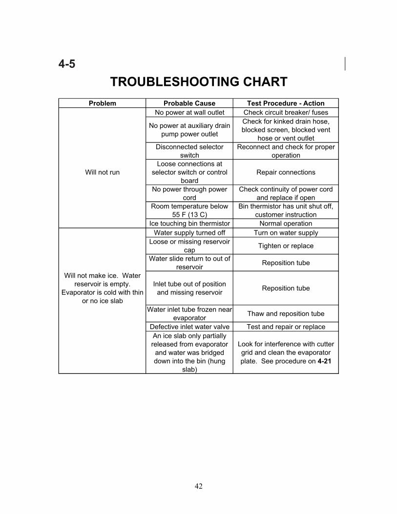
4-5
Problem Probable Cause Test Procedure - ActionNo power at wall outlet Check circuit breaker/ fuses
No power at auxiliary drain pump power outlet
Check for kinked drain hose, blocked screen, blocked vent
hose or vent outletDisconnected selector
switchReconnect and check for proper
operation
Will not runLoose connections at
selector switch or control board
Repair connections
No power through power cord
Check continuity of power cord and replace if open
Room temperature below 55 F (13 C)
Bin thermistor has unit shut off, customer instruction
Ice touching bin thermistor Normal operationWater supply turned off Turn on water supply
Loose or missing reservoir cap Tighten or replace
Water slide return to out of reservoir Reposition tube
Will not make ice. Water reservoir is empty.
Evaporator is cold with thin or no ice slab
Inlet tube out of position and missing reservoir Reposition tube
Water inlet tube frozen near evaporator Thaw and reposition tube
Defective inlet water valve Test and repair or replaceAn ice slab only partially released from evaporator
and water was bridged down into the bin (hung
slab)
Look for interference with cutter grid and clean the evaporator plate. See procedure on 4-21
TROUBLESHOOTING CHART

43
4-6
Problem Probable Cause Test Procedure - ActionSlab will not release during harvest due to scale buildup
Clean evaporator plate; See procedure on 4-21
Will not make ice. Water reservoir is empty. Evaporator
is cold with 3/4 inch thick or larger ice slab.
Defective or disconnected hot gas valve Test and repair or replace
Defective hot gas valve Test and repair or replaceRoom temperature over 100 F
(38 C) Customer instruction
Seeping water valve condenser is hot Replace water valve
Partial refrigerant leak or restriction (u-shaped slab)
Check for leak/restriction and repair or replace defective
componentWill not make ice. Water
reservoir is full. Evaporator is cold with thin, partial, irregular
or no ice slab.
Blocked condenser or stalled fan motor
Clean condenser, repair or replace motor
Tube not attached to outlet of recirculating pump Re-attach tube
Defective recirculating pump Repair or replace the pump motor assembly
Partially blocked water distributor Clean distributor and evaporator
Compressor is not running Test compressor, relay and overload
Will not make ice. Water reservoir is full. Evaporator is
warm.
Blocked condenser or stalled fan motor
Clean condenser, repair or replace motor
Unit is in the start-up mode Wait 5 minutes and re-checkRoom temperature below 55 F
(13 C)Bin thermistor has unit shut off,
customer instruction
Poor ice production. Seeping water valve condenser is hot Replace water valve
Slow or defective drain or drain pump causing water to back up
into the bin
Repair or replace drain or drain pump
TROUBLESHOOTING CHART (continued)

44
4-7
Problem Probable Cause Test Procedure - ActionToo much ice in bin Defective bin thermistor Replace
Banging sound
The slab dropping off the plate and ice dropping from the cutter grid into an empty bin are normal
sounds
Noisy Grinding, cavitating sound
The reservoir is empty. Look for a partially released slab,
interference with cutter grid, etc., and clean the evaporator plate.
See procedure on 4-21Grinding, cavitating sound from recirculation pump
If the reservoir is full, replace the pump
Noisy drain pump Repair or replaceIce freezing together in the
bin Normal This is normal with low customer usage
Cloudy, poor tasting ice Poor water quality See chart on 4-2 & 4-3
Off LED flashing 2 blinks Open or disconnected bin thermistor or thermistor wiring
Test thermistor and wiring harness or reconnect
Off LED flashing 3 blinksDefective, loose, or mis-positioned evaporator
thermistor
Test thermistor and wiring harness or reconnect
TROUBLESHOOTING CHART (continued)

45
4-8DIAGNOSTIC FLOW CHARTS FORICE MAKER CONTROL BOARDOVERVIEW
4-9Flush Mode: (6 minutes maximum) The Flush Mode begins every time the user plugs the ice machine in, the interface is changed to “On” from “Off”, when the ice maker is turned on after the completion of the Clean cycle or (drain pump models only) power will be turned off If the water level in the drain pump rises, due to a slow or blocked drain, or a blocked vent hose, and touches the “overfill” contact,
Power is applied or icemaker turned on at the user interfacea) Water valve fills 45 ounces maximum Fill time 2 minutesb) Recirculation pump runs for 1 minutec) Reservoir drain pump, on 20 sec., off for 20 sec., On 20 sec.d) Water valve fills, selected volume maximum Fill time 2 minutese) Enter Freeze Mode
4-10Freeze Mode:Time in this mode is dependent on the water level in the reservoir. There is no minimum time, (if water level drops below sensor before 5 minutes the control counts a Hung Slab) and the maximum time is 25 minutes.
a) Compressor, condenser fan and recirculate pump are energizedb) Water level drops below water sensor---enter Harvest Mode. Note: if water level drops below sensor before 5 minutes the control counts a Hung Slab, if water level sensor not detected control sets a 25 minute freeze time
4-11Harvest Mode:Time in this mode will be 2 to 17 minutes, dependent on the condition of the evaporator thermistor. Compressor and hot gas valve on for a minimum of 1 minNote: 4 minutes fixed cycle time if evaporator thermister is disconnected or open.
Harvest Mode: Bin Not Full: Reservoir drain pump On for 20 seconds,Off 20 seconds, back On for 20 seconds and if:
a) Bin thermistor greater than 36F compressor and hot gas valve on (minimum of 1 minute), measured water fill is requested---Evaporator thermister greater than 52F and more than 1 minute but less 16 minutes have passed or

46
b) Evaporator thermistor unplugged or open, after 4 minutesContinue Freeze Mode.
Harvest Mode: Bin Full: Note: 5 minutes minimum, continues as long as the bin is full (Bin thermistor remains less than 36 deg)
a) Bin thermistor less than 36F, compressor and hot gas valve on (minimum of 1 minute) Evaporator thermistor greater than 52F more than 1 minute but less 16 minutes have passed or
b) Evaporator thermistor unplugged or open, 4 minutes have passedIdle Mode: Time in this mode is dependent on the temperature at the bin thermistor.
Bin not full (Bin thermister greater than 36 deg) the control sends a reservoir fill request and Freeze Mode begins
FAILURE MODE: while in Harvest Mode Evaporator thermistor less than 52F and more than 16 minute have passed--- Harvest Fail Off LED flashes 3 blinks)
4-12Failure Mode: This mode will last indefinitely until the failure is corrected.
a) OFF LED is flashing 3 blinks, look for an evaporator thermistor that has not reached 52°F. This may be due to an Evaporator thermister unplugged or open, loose or improperly positioned thermistor, a hot gas failure, a sealed system leak or restriction.b) OFF LED is flashing 2 blinks; look for a disconnected or open bin thermister, the bin thermistor is constantly checked during the Flush, the end of each Freeze Mode, Harvest Modes, and Idle Mode.
4-13Clean Mode: (70 minutes) The Clean Mode may only be selected while the icemaker is turned off (off button held 3 sec) at the user interface.
Clean Mode begins (clean light flashes 1 sec on 1 sec off)a) Circulation pump, compressor and hot gas valve are energized for 40
min,b) Water valve energized for 3 minutes then recirculate pump for 3
minutes repeated 5 times for total of 30 minutes—c) Turn all components Off Clean LED remains On with reservoir full.
NOTE: At the end of the Clean Mode, the icemaker will stay OFF. Clean LED will be on green and Off LED on Red. The reservoir is to be drained by the consumer prior to restarting the icemaker. Consumer must select OFF for 3 seconds before selecting ON.
4-14
47
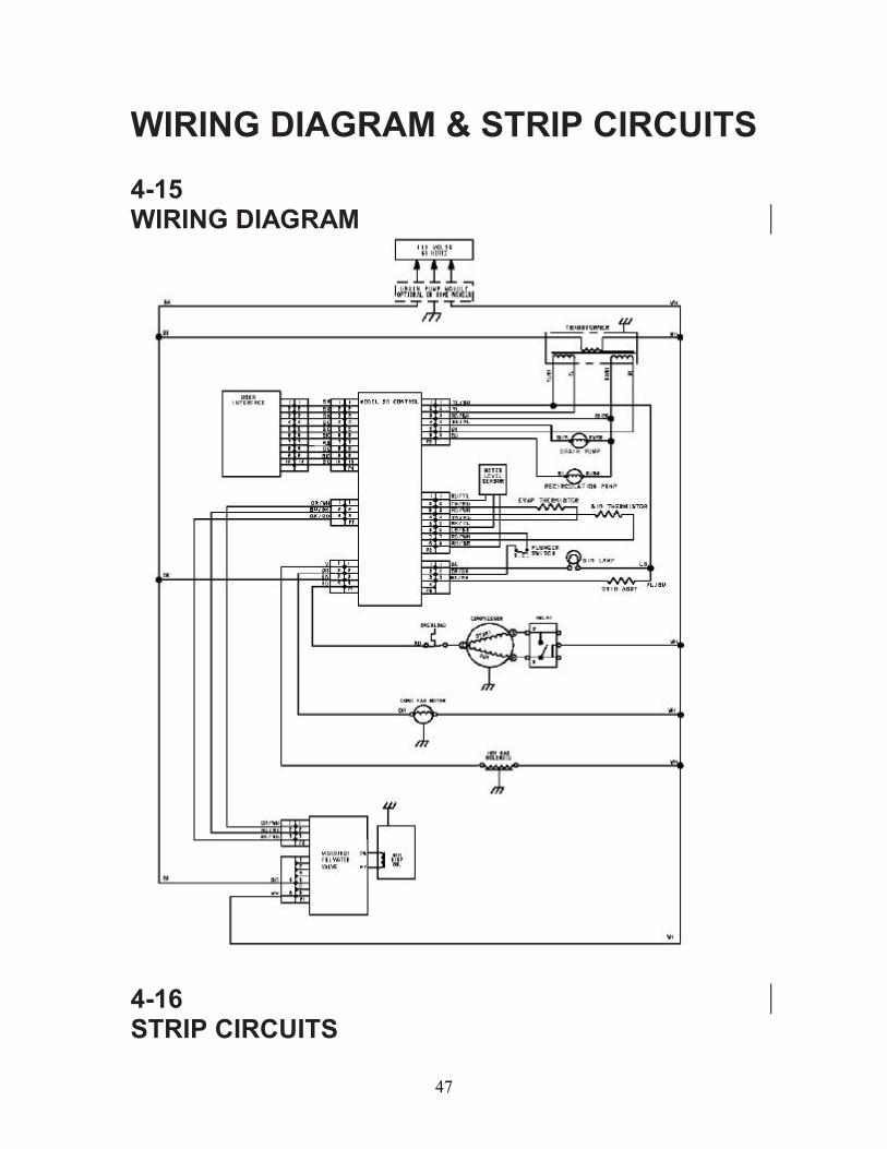
WIRING DIAGRAM & STRIP CIRCUITS
4-15WIRING DIAGRAM
4-16STRIP CIRCUITS

48
4-17FLUSH
4-18ICE MAKING MODE
4-19HARVEST MODE
4-20CLEAN MODE

49
4-21CONNECTORWIRE COLORS COMPONANT OHMs VOLTAGE
P1-1 VIOLET Hot Gas Coil 385 120 v acto White wire on transformer
P1-2 ORANGECondenser Fan Motor 185 120 v ac
to White wire on transformer
P1-3 2 BLACKLine in & line to transformer 3.5 to 4.5 120 v ac
to White wire on transformer
P1-4 RED Compressor 120 v acto White wire on transformer
P3-1 YELLOW/BLACK Grid & Transformer 20 8.4 v ac to P6-3 Bk/WhP3-1 LIGHT BLUE Bin Light 8.4 v ac to P6-1 BkP3-2 YELLOW Transformer .11 to .14 8.4 v ac to P3-1 Yl/BkP3-3 RED/BLACK Recirculate Pump 3.6 12 v ac to P3-6 Bl
P3-3 RED/BLACKReservoir Drain Pump 3.6 12 v ac to P3-4 Bl/Yl
P3-3 RED/BLACKRed/Black toRed wire of Transformer .14 to .18 12 v ac to P3-5 Gray
P3-4DARKBLUE/YELLOW
Resevoir Drain Pump 3.6 12 v ac to _P3-3 Rd/Bk
P3-5 GRAYRed wire on Transformer .14 to .18 12 v ac to _P3-3 Rd/Bk
P3-6 BLUE Recirculate Pump 3.6 12 v ac to _P3-3 Rd/Bk
P5-1 RED/YELLOW Water Level Sensor See section 1-19
P5-2 TAN/REDEvaporatorThermister See Chart 3-3 to P5-4 Tn/Rd
P5-3 RED/WHITE Bin Thermister See Chart 3-3 to P5-7 Rd/Wh
P5-4 TAN/REDEvaporatorThermister See Chart 3-3
P5-5 BLACK/YELLOW Water Level Sensor See section1-19P5-6 BLUE/BLACK Light Switch to P6-2 Or/BkP5-7 RED/WHITE Bin Thermister See Chart 3-3 to P5-3 Rd/WhP5-8 WHITE/BROWN Water Level Sensor See section1-19
P6-1 BLACK Light Door Open 8.4 v ac to P3-1 Lt BlP6-2 ORANGE/BLACK Light Switch to P5-6 Bk/BlP6-3 BLACK/WHITE Grid 20 to P3-1 Yl/BkP6-4 BLANK
P7- ORANGE/WHITEMeasured Fill Water valve 14 v dc to P7 Bk/Rd
P7-DARKBLUE/BLACK
Measured Fill Water valve communication
P7- BLACK/REDMeasured Fill Water valve 14 v dc to P7 Or/Wh

50
4-22CLEANING THE EVAPORATOR PLATENOTE: Use one Ice Maker Cleaner WX08X42870. For best performance, do not use any other type of ice machine cleaner in the ice maker.1. Press and hold the OFF keypad to turn the unit off.2. For easier access to the evaporator, remove the cutter grid (see 2-4).3. Remove the ice from the bin.4. Unscrew the drain cap from the reservoir and allow the reservoir to drain completely and then reinstall the drain cap.5. Read and follow all of the handling information that was supplied with the ice machine cleaner. IMPORTANT: Use the entire bottle to clean the unit.6. Open the bottle and pour a small amount of cleaning solution on a non scratching, blue Scotch-Brite™ pad.7. Using only front-to-back motions, clean the top of the plate, the sidewalls, and the front edge of the evaporator. The front-to-back motion is important to avoid scratches that could keep the ice slab from sliding off the evaporator plate.NOTE: More solution may be necessary if there is a large amount of scale buildup on the evaporator. The scrubbing process may take ten minutes or more, depending on the amount of scale buildup on the plate. The entire plate should feel smooth when the cleaning is finished.8. Pour the remaining solution from the bottle into the water reservoir. Using the empty bottle, fill the reservoir with clean water to within 1/4" of the top of the overflow port.9. Press and hold the Clean keypad. The Clean light will blink to show that the Clean cycle is in progress. When the Clean LED turns solid and Off LED is On (after approximately 70 minutes), the cleaning cycle is complete. During the cleaning cycle, the system both cleans and rinses itself.10. After the cleaning cycle is complete, remove the drain cap from the water reservoir, and see if any cleaning solution is left in the water as it drains out. If the water is green in color from the cleaning solution, it will be necessary to run another cleaning cycle to flush the system. Be sure to replace the drain cap securely to avoid leaking.11. When the flushing process is completed, Consumer must select OFF for 3 seconds before selecting ON to resume ice production.
4-23WARRANTY INFORMATION SOURCES
IN THE UNITED STATES:

51