carburetion manual -...
TRANSCRIPT

CARBURETION
MANUAL
© 2001 American Honda Motor Co., Inc.—All Rights Reserved
TM044PSV52939
IPC 1500.2001.12
Printed in U.S.A.
CA
RB
UR
ETION
MA
NU
AL
Printed onRecycled Paper
C:\...\COREL\COVER\COVERIPC.CDRSun Dec 09 17:38:10 2001
Color profile: _DEFAULT.CCS - Generic CMYK Color PrinterComposite Default screen

A FEW WORDS ABOUT SAFETY
SERVICE INFORMATION
The service and repair information contained in this manual is intended for use by qualified, professional technicians.
Attempting service or repairs without the proper training, tools, and equipment could cause injury to you and others. It
could also damage the product or create an unsafe condition.
This manual describes the proper methods and procedures for performing service, maintenance, and repairs. Some
procedures require the use of special tools. Any person who intends to use a replacement part, service procedure, or a
tool that is not recommended by Honda, must determine the risks to their personal safety and the safe operation of the
product.
If you need to replace a part, use genuine Honda parts with the correct part number, or an equivalent part. We strongly
recommend that you do not use replacement parts of inferior quality.
For Your Customer’s Safety
Proper service and maintenance are essential to the
customer’s safety and the reliability of the product. Any error or
oversight while servicing a product can result in faulty
operation, damage to the product, or injury to others.
For Your Safety
Because this manual is intended for the professional service
technician, we do not provide warnings about many basic shop
safety practices (e. g., Hot parts – wear gloves). If you have not
received shop safety training or do not feel confident about
your knowledge of safe servicing practices, we recommend
that you do not attempt to perform the procedures described in
this manual.
Some of the most important general service safety precautions
are given below. However, we cannot warn you of every
conceivable hazard that can arise in performing service and
repair procedures. Only you can decide whether or not you
should perform a given task.
Important Safety Precautions
• Make sure you have a clear understanding of all basic shop safety practices and that you are wearing appropriate clothing and using safety equipment. When performing any service task, be especially careful of the following:
❐ Read all of the instructions before you begin, and make sure you have the tools, the replacement or repair parts, and the skills required to perform the tasks safely and completely.
❐ Protect your eyes by using proper safety glasses, goggles, or face shields any time you hammer, drill, grind, or work around pressurized air or liquids, and springs or other stored-energy components. If there is any doubt, put on eye protection.
❐ Use other protective wear when necessary, for example, gloves or safety shoes. Handling hot or sharp parts can cause severe burns or cuts. Before you grab something that looks like it can hurt you, stop and put on gloves.
• Make sure the engine is off before you begin any servicing procedures, unless the instruction tells you to do otherwise. This will help eliminate several potential hazards:
❐ Carbon monoxide poisoning from engine exhaust. Be sure there is adequate ventilation whenever you run the engine.
❐ Burns from hot parts. Let the engine and exhaust system cool before working in those areas.
❐ Injury from moving parts. If the instruction tells you to run the engine, be sure your hands, fingers, and clothing are out of the way.
• Gasoline vapors are explosive. To reduce the possibility of a fire or explosion, be careful when working around gasoline.
❐ Use only a nonflammable solvent, not gasoline, to clean parts.
❐ Never drain or store gasoline in an open container.
❐ Keep all cigarettes, sparks, and flames away from all fuel-related parts.
�WARNING
Improper service or repairs can create an unsafe
condition that can cause your customer or others
to be seriously hurt or killed.
Follow the procedures and precautions in this
manual and other service materials carefully.
�WARNING
Failure to properly follow instructions and
precautions can cause you to be seriously hurt
or killed.
Follow the procedures and precautions in this
manual carefully.
me-carb.book Page 0 Sunday, December 9, 2001 5:12 PM

iDate of Issue: December 2001
© American Honda Motor Co., Inc.
PREFACE
This manual provides a wide range of information about
Honda Marine carburetor systems.
All Honda Marine engines produced since 1998 comply
with EPA regulations and all Honda Marine engines
produced in 2001 meet CARB regulations. You will find
a full explanation of these regulations in the Honda
Marine Emission Regulation Guide.
All information contained in this manual is based on the
latest product information available at the time of
printing. We reserve the right to make changes at any
time without notice.
No part of this publication may be reproduced, stored in
retrieval system, or transmitted, in any form by any
means, electronic, mechanical, photocopying,
recording, or otherwise, without the prior written
permission of the publisher. This includes text,
drawings, photographs and tables.
As you read this manual, you will find information that is
preceded by a NOTICE symbol. The purpose of this
message is to help prevent damage to the product,
other property, or the environment.
SAFETY MESSAGES
Your safety, and the safety of others, are very important.
To help you make informed decisions, we have
provided safety messages and other safety information
throughout this manual. Of course, it is not practical or
possible to warn you about all the hazards associated
with servicing these carburetor systems. You must use
your own good judgement.
You will find important safety information in a variety of
forms, including:
• Safety Labels—on the product.
• Safety Messages—preceded by a safety alert
symbol and one of three signal words: DANGER,
WARNING, or CAUTION.
These signal words mean:
You WILL be KILLED or
SERIOUSLY HURT if you
don't follow instructions.
You CAN be KILLED or
SERIOUSLY HURT if you
don’t follow instructions.
You CAN be HURT if you
don’t follow instructions.
• Instructions—how to service carburetor systems
correctly and safely.
American Honda Motor Co., Inc.
Marine Technical Support Group
���� DANGER
���� WARNING
���� CAUTION
CONTENTS
INTRODUCTION 1
SERVICE RULES 2
FUNCTION 3
SPECIAL/COMMERCIALLY
AVAILABLE TOOLS4
FUEL DELIVERY 5
TROUBLESHOOTING/
DISASSEMBLY/CLEANING6
ASSEMBLY/ADJUSTMENT 7
STORAGE 8
TESTING DYNAMIC/STATIC 9
HIGH ELEVATION OPERATION 10
EMISSION REGULATIONS 11
INDEX 12
me-carb.book Page i Sunday, December 9, 2001 5:12 PM

iiDate of Issue: December 2001
© American Honda Motor Co., Inc.
ABBREVIATIONS TERMINOLGY
API American Petroleum Institute
Approx. Approximately
Assy. Assembly
ATDC After Top Dead Center
BAT Battery
BDC Bottom Dead Center
BTDC Before Top Dead Center
Comp. Complete
CYL Cylinder
EX Exhaust
F Front or Forward
GND Ground
H/C Honda Code
ID Identification
IG or IGN Ignition
IN Intake
L. Left
OHC Over Head Cam
OHV Over Head Valve
OM Owner’s Manual
OP Optional Part
PCV Positive Crankcase Ventilation
P/N Part Number
Qty Quantity
R. Right
SV Side Valve
SM Shop Manual
STD Standard
SW Switch
TDC Top Dead Center
WOT Wide Open Throttle
VOM Volt-Ohm Meter
Term used in
this manual
Term used in
other Honda
publications
Part
Illustration
Slow Jet Pilot Jet
Slow Jet
Tube
(BF9.9 and BF15)
Jet Set
Pilot Jet
Slow Jet
Jet Nozzle
Slow Jet
Emulsion Tube
(BF20 ~ BF90)
Idle Mixture
Screw
Pilot
Screw
Main Emulsion
Tube
Main
Nozzle
me-carb.book Page ii Sunday, December 9, 2001 5:12 PM

7–1Date of Issue: December 2001
© American Honda Motor Co., Inc.
ASSEMBLY/ADJUSTMENT 7
me-carb.book Page 1 Sunday, December 9, 2001 5:12 PM

7–2Date of Issue: December 2001
© American Honda Motor Co., Inc.
NECESSARY PARTS
• Intake manifold and carburetor mounting flange gaskets are normal stock items.
• Carburetor packing sets:
Honda does not offer ″carburetor kits ″ as a replacement part. They are seldom needed. You can buy the
carburetor O-rings in a kit referred to as a Packing Set. If the wrong cleaner comes in contact with these
O-rings, they will swell and you will need new ones. These are normal stock items.
• Float valves (also known as needle-and-seat):
You can't replace Honda ″ float seats ″ but the float valves are available separately, as are all the
removable components in Honda carburetors. These are normal stock items.
• Slow jet tubes and slow jet emulsion tubes:
If these really get varnished and are too difficult to clean, they should be replaced. It is a good idea to
stock an assortment to fit the various BF9.9 ~ BF90 models. This can save time and avoid frustration.
• Idle mixture screw sets for emission-controlled models:
When the mixture screws are removed per SM procedures, you will need new idle mixture screw
assemblies.
• Collars 6.5 x 11 x 7.5 mm (P/N 17202-ZV5-300):
These are found in the air silencer covers and carburetor mounting/silencer plates. These are often
missing after the carburetors have been serviced, since they easily fall out and become lost.
• Bulk fuel hose:
Bulk hose is shown in section 3 of the Honda Marine DPPL. Replacement ″ formed fuel ″ hose, such as
the hose from the BF50A fuel filter to the fuel pump, is also included in the DPPL.
Hoses can be damaged during removal or become hard and difficult to work with.
• Water separator/filters:
Three different sizes are listed in the Honda Marine Accessory Catalog.
• Yellow fingernail polish or yellow model paint:
This is used for re-marking the carburetor synchronization adjustment screws.
After finishing the repair job, the engine should look like new and should not look like it has been ″worked
on ″ before. Having the correct replacement parts on hand assures you of neat, clean, proper back-to-
factory-specification service work.
me-carb.book Page 2 Sunday, December 9, 2001 5:12 PM

7–3Date of Issue: December 2001
© American Honda Motor Co., Inc.
CARBURETOR SPECIFICATIONS
Always compare to SM for new model information, pertinent revisions, and most current information.
* Not applicable** With removable jet
† Emission engine† † Engine serial number BAYE-2007400 to subsequent
Specifications are subject to change without notice.
MODEL hpSLOW
JET
PRIMARY
JET
MAIN
JET
FLOAT
LEVEL
MIXTURE SCREW IDLE
SPEEDNon-Emission Emission
BF20
BF2A2 #35 *
#70
#60
10.5 - 13.5 mm
(0.413 - 0.531")
BF20S: 2 turns
(engine serial
number
1000001 -
1007046)
1-3/4 turns
(engine serial
number
1007047 to
subsequent)
BF20L, BF2A:
2-1/8 turns
*
1-1/4 turns
Standard flywheel:
1,400 ± 100 rpm
Trolling flywheel:
Standard Idle,
1,300 ± 100 rpm
Trolling Idle,
950 ± 50 rpm
BF2D 2 #35 * #6512 mm
(0.47")* 2 turns 2,000 ± 100 rpm
BF50
BF5A5
#35
#40* #75
9.0 - 11.0 mm
(0.35 - 0.43")2-3/8 turns 1-3/4 turns
In forward:
1,300 ± 100 rpm
In neutral:
1,550 ± 50 rpm
BF75
BF100
7.5
10#35 * #88
9.85-10.15 mm
(0.388 - 0.40")Highest rpm *
In neutral:
1,200 ± 100 rpm
BF8A 8#35
#42 *** #88
9.85-10.15 mm
(0.388 - 0.40")Highest rpm 2-1/2 turns
In neutral:
1,200 ± 100 rpm
BF9.9A
BF15A
9.9
15
#48
#52
*
#102
#108
13 - 15 mm
(0.51 - 0.59")
2-3/4 turns
1-5/8 turns
3 turns
1-5/8 turns
In neutral:
1,100 ± 50 rpm
BF25A
BF30A
25
30
#35
#38†
#38
*
#100
#110
14 mm (0.6")
13 mm (0.5")
2 turns
3 turns
2-3/4 turns
3 turns
In neutral:
900 ± 50 rpm
BF35A
BF45A
35
45
#38
#42
*
#102
#125
14 mm (0.6")
2-1/8 turns
2-1/8 turns
*
*
In neutral:
950 ± 50 rpm
BF40A
BF40A1† †
BF50A
40
50
#38
#42
*
#92
#130
14 mm (0.6")
13 mm (0.5")
*
*
*
2-1/4 turns
1-5/8 turns
1 turn
In neutral:
950 ± 50 rpm
BF75A
BF90A
75
90
#42
#40
#38
#100 †
#52
#80 †
#128
#132
11.5 mm
(0.45")
1-7/8 turns
2-1/4 turns
1-7/8 turns
2-1/4 turns
In neutral:
950 ± 50 rpm
me-carb.book Page 3 Sunday, December 9, 2001 5:12 PM

7–4Date of Issue: December 2001
© American Honda Motor Co., Inc.
ASSEMBLY
Check the jet size numbers to ensure the proper size jets are installed, especially if the carburetors had
been worked on before and/or the engine had an abnormally rich or lean running condition.
Assembly drawings are shown on the following pages along with some additional assembly notes.
1. Install the jets and on the BF9.9 through BF90 carburetors, lube the slow jet emulsion tube O-ring with
silicone spray and insert the slow jet emulsion tube into the main emulsion tube, then install the two
tubes at the same time. This makes slow jet emulsion tube alignment much easier.
2. Check the float valve tip. Replace the float valve if it is worn or damaged. Install the float valve onto the
float tab, then install the float and float valve assembly into the carburetor. After installing the float and
float valve assembly, always check the float level adjustment (P. 7-11).
3. Install the float chamber and tighten the screws in a crisscross pattern.
4. Install the idle mixture screw and set per specifications (P. 7-3).
On emission engines, wait to install the tamper resistant caps or plugs until after the engine has been run and the idle mixture screw adjustment sensitivity has been checked (P. 7-12 step 3).
5. On 3 and 4 cylinder models, scrape the gasket from the intake manifold then assemble the carburetors
on the intake manifold using new gaskets.
Make sure the gasket is properly located on the air silencer alignment pins and tighten the carburetor mounting bolts in 2 to 3 steps, back and forth.
Make sure the accelerator device has been inspected (P. 6-47). Grease the throttle and choke linkage and snap them into place.
Scrape the intake manifold gasket off the cylinder head using a carefully sharpened and deburred gasket scraper. The gasket surface must not be scratched or gouged and must retain a machined surface.
NOTICE
Do not use a drill with abrasive pads or a die grinder on the intake manifold or cylinder head surfaces.
Metal will be removed and the gasket may leak.
Now is a good time to check for salt, sand, and mineral deposit buildup in the coolant passages. It will show up in the small water jackets in the cylinder head next to the intake ports. Also, check for sacrificial anode deterioration on applicable models.
Install the intake manifold gasket dry without any gasket sealer, then torque the mounting bolts and nuts in 2 to 3 steps from inside to the outside.
Check all hoses and linkage.
me-carb.book Page 4 Sunday, December 9, 2001 5:12 PM

7–5Date of Issue: December 2001
© American Honda Motor Co., Inc.
6. Before connecting a fuel hose to a fuel pump or carburetor, use the priming bulb and purge a little fuel
through the hose into an approved container. This will remove any loose particles from inside the hose
before the hoses are connected to their respective fittings. This will also prevent loose particles from
getting under the float valve, causing a carburetor to overflow or plug a jet.
If the hoses are sprayed with silicone spray, they will generally slide right onto their fittings. If the fuel condition is questionable, replace the fuel and fuel filters. Don’t use worm type hose clamps because they will damage the hose. Use only the original hose clips.
7. Check for full throttle opening whenever the outboard is being serviced and especially anytime the
carburetors or rigging have been serviced.
A number of complaints about low power can be traced to throttles not fully opened when the control lever is in the full open throttle position.
8. Start the engine and warm it up to normal operating temperature.
On today’s emission controlled engines, it is critical the engine run at the correct temperature. Make sure the engine is running at the correct temperature, especially if a rich running condition was recorded prior to carburetor disassembly. Remember, proper fuel vaporization is dependent on engine temperature. Refer to the thermostat dynamic test procedure (P. 9-3).
9. Check the idle speed adjustment and on 3 and 4 cylinder models synchronize the carburetors (P. 7-12).
me-carb.book Page 5 Sunday, December 9, 2001 5:12 PM

7–6Date of Issue: December 2001
© American Honda Motor Co., Inc.
BF2 • BF20 • BF2D (BF CARBURETOR)
Always use a No. 2 Phillips® screwdriver that does not have worn flutes, and a cabinet screwdriver that fits
tightly into the main jet slot.
CARBURETOR BODY COVER
SLOW JET
Apply silicone
spray to the O-ring.
O-RING
3 x 6 SCREW (2)
LEVER SETTING PLATE
LEVER SPRING
FUEL VALVE LEVER
FUEL VALVE PACKING
MAIN EMULSION TUBE
O-RING
MAIN JET
Jet size shown by XX.
FLOAT
DRAIN SCREWSETTING BOLT
SEALING WASHER
FLOAT CHAMBER
FLOAT CHAMBER GASKET
FLOAT PIN
FLOAT
VALVE
SPRING
FLOAT VALVE
VALVE SEAT
NORMAL WORN
THROTTLE STOP SCREW
ATMOSPHERIC VENT
CLEAR TUBE
4 x 12 SCREW (4)
CARBURETOR MAIN WELL
LIMITER CAP
INSTALLATION:
Refer to the EMISSION
REGULATIONS chapter P. 11-3.
IDLE MIXTURE SCREW
CARBURETOR BODY COVER O-RING
me-carb.book Page 6 Sunday, December 9, 2001 5:12 PM

7–7Date of Issue: December 2001
© American Honda Motor Co., Inc.
BF5 • BF50 • BF75 • BF8 • BF100 (BC CARBURETOR)
Always use a No. 2 Phillips® screwdriver that does not have worn flutes, and a flat-tip screwdriver that fits
tightly into the main jet slot.
FLOAT CHAMBER
DRAIN TUBE
FLOAT
DRAIN SCREW
4 x 12 mm
SCREW (4)
FLOAT VALVE
FLOAT PIN
FLOAT VALVE
DRAIN SCREW
4 x 12 SCREW (2)
FLOAT
MAIN EMULSION TUBE
CARBURETOR BODY
THROTTLE
STOP SCREW
SLOW
JET
THROTTLE
STOP SCREW
SLOW JET
ACCESS SCREW
IDLE MIXTURE
SCREW
CARBURETOR
BODY
FLOAT PIN
MAIN EMULSION
TUBE
BF75 • BF8 • BF100 CARBURETOR
Early model BF75 • BF100 carburetors used a slow
jet access screw similar to the BF5 • BF50 shown
below.
BF5 • BF50 CARBURETOR
Late model BF5 carburetors used a removable slow jet
and a mixture screw plug similar to the BF75 • BF8 •
BF100 shown above.
MAIN JET
Jet size shown by XX.
MAIN JET
Jet size shown by XX.
IDLE MIXTURE SCREW PLUG
INSTALLATION:
Refer to the
EMISSION
REGULATIONS
chapter
P. 11-3.
CARBURETOR MAIN WELL
IDLE MIXTURE SCREW
me-carb.book Page 7 Sunday, December 9, 2001 5:12 PM

7–8Date of Issue: December 2001
© American Honda Motor Co., Inc.
BF9.9 • BF15 (BG CARBURETOR)
Always use a No. 2 Phillips® screwdriver that does not have worn flutes, and a flat-tip screwdriver that fits
tightly into the main jet and plug cap slots.
FLOAT CHAMBER
FLOAT PIN
FLOAT VALVE
DRAIN SCREW
4 x 16 SCREW (4)
FLOAT
MAIN EMULSION TUBE
INSTALLATION:
To help slow jet tube alignment, install the slow jet
tube and main emulsion tube at the same time.
CARBURETOR BODY
THROTTLE
STOP SCREW
PLUG CAP
MAIN JET
Jet size shown by XX.
SLOW JET TUBE
INSTALLATION:
Apply silicone spray to the O-ring.
To help slow jet tube alignment,
install the slow jet tube and main
emulsion tube at the same time.
Jet size shown by XX.
CARBURETOR MAIN WELL
LIMITER CAP
INSTALLATION:
Refer to the EMISSION
REGULATIONS chapter P. 11-3.
IDLE MIXTURE SCREW
O-RING
O-RING
me-carb.book Page 8 Sunday, December 9, 2001 5:12 PM

7–9Date of Issue: December 2001
© American Honda Motor Co., Inc.
BF20 • BF25 • BF30 • BF35 • BF40 • BF45 • BF50 (BG CARBURETOR)
Always use a No. 2 Phillips® screwdriver that does not have worn flutes, and a flat-tip screwdriver that fits
tightly into the main jet and plug cap slots.
FLOAT CHAMBER
IDLE MIXTURE SCREW
FLOAT PIN
FLOAT VALVE
DRAIN SCREW
4 x 16 SCREW (4)
FLOAT
CARBURETOR BODY THROTTLE
STOP SCREW
PLUG CAP
MAIN JET
Jet size shown by XX.
CARBURETOR MAIN WELL
LIMITER CAP
INSTALLATION:
Refer to the EMISSION
REGULATIONS chapter P. 11-3.
O-RING
MAIN EMULSION TUBE
INSTALLATION:
To help slow jet emulsion tube
alignment, install the slow jet
emulsion tube and main
emulsion tube at the same time.
SLOW JET EMULSION TUBE
INSTALLATION:
Apply silicone spray to the O-ring.
To help slow jet emulsion tube
alignment, install the slow jet
emulsion tube and main emulsion
tube at the same time.
Jet size shown by XX.
O-RING
chap7.fm Page 9 Sunday, December 9, 2001 6:56 PM

7–10Date of Issue: December 2001
© American Honda Motor Co., Inc.
BF75 • BF90 (BG CARBURETOR)
Always use a No. 2 Phillips® screwdriver that does not have worn flutes, and a flat-tip screwdriver that fits
tightly into the main jet, primary jet, and plug cap slots.
FLOAT CHAMBER
IDLE MIXTURE SCREW
FLOAT PIN
FLOAT
VALVE
DRAIN
SCREW
4 x 16 SCREW (4)
FLOAT
CARBURETOR BODY
THROTTLE
STOP SCREW
PLUG CAP
MAIN JET
Jet size shown by XX.
CARBURETOR MAIN WELL
PREHEATER
PLUG BOLT
PRIMARY JET
Jet size shown by XX.
LIMITER CAP
INSTALLATION:
Refer to the
EMISSION
REGULATIONS
chapter P. 11-3.
O-RING
SLOW JET EMULSION TUBE
INSTALLATION:
Apply silicone spray to the O-ring.
To help slow jet emulsion tube
alignment, install the slow jet
emulsion tube and main emulsion
tube at the same time.
Jet size shown by XX.
O-RING
MAIN EMULSION TUBE
INSTALLATION:
To help slow jet emulsion
tube alignment, install the
slow jet emulsion tube
and main emulsion tube
at the same time.
chap7.fm Page 10 Sunday, December 9, 2001 6:57 PM

7–11Date of Issue: December 2001
© American Honda Motor Co., Inc.
ADJUSTMENTS
Float Level
On the BF and BC type carburetors which
use spring loaded float valves, do not
depress the spring when checking the float
adjustment (P. 3-4).
1. Position the carburetor on the workbench
as shown. Raise the float, and slowly
lower it until the float valve just contacts
the seat.
2. Adjust the float gauge to the desired
specification shown on the graduated
scale (1) by sliding the float level indicator
(2) up or down as needed.
3. Adjust the legs by sliding the support arm
(3) until the legs clear the float and rest on
the float chamber mating surface. The
gauge should go over the main jet at 90°
to the carburetor body, and be parallel to
the float pin.
4. Slowly lower the gauge to the float
chamber mating surface as you look at
the gap between the gauge and the float.
The gap should disappear just as the legs
contact both sides of the float chamber
mating surface.
5. If the level is outside the specification,
gently bend the brass float tab (4) to
adjust the float level. All carburetors have
adjustable brass float tabs except the
BF2.
As a general rule, the float should be parallel
to the float chamber mating surface when
viewed from the side as shown. Always
measure the float level and set to
specifications.
Because all three float valves have a
synthetic rubber tip, they generally do not
require replacement.
Possible reasons for float valve replacement:
• Varnish contamination on the tip
• Varnish contamination along the side ribs
• A sticky spring on BF or BC carburetor
• Damage to rubber float tip
2
3
1
4
me-carb.book Page 11 Sunday, December 9, 2001 5:12 PM
7–12Date of Issue: December 2001
© American Honda Motor Co., Inc.
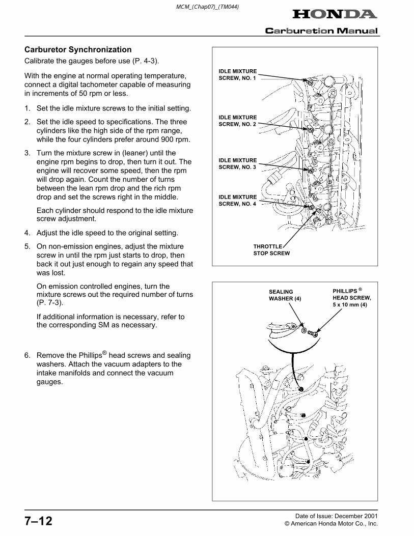
Carburetor Synchronization
Calibrate the gauges before use (P. 4-3).
With the engine at normal operating temperature,
connect a digital tachometer capable of measuring
in increments of 50 rpm or less.
1. Set the idle mixture screws to the initial setting.
2. Set the idle speed to specifications. The three
cylinders like the high side of the rpm range,
while the four cylinders prefer around 900 rpm.
3. Turn the mixture screw in (leaner) until the
engine rpm begins to drop, then turn it out. The
engine will recover some speed, then the rpm
will drop again. Count the number of turns
between the lean rpm drop and the rich rpm
drop and set the screws right in the middle.
Each cylinder should respond to the idle mixture screw adjustment.
4. Adjust the idle speed to the original setting.
5. On non-emission engines, adjust the mixture
screw in until the rpm just starts to drop, then
back it out just enough to regain any speed that
was lost.
On emission controlled engines, turn the mixture screws out the required number of turns (P. 7-3).
If additional information is necessary, refer to the corresponding SM as necessary.
6. Remove the Phillips® head screws and sealing
washers. Attach the vacuum adapters to the
intake manifolds and connect the vacuum
gauges.
IDLE MIXTURE
SCREW, NO. 1
THROTTLE
STOP SCREW
IDLE MIXTURE
SCREW, NO. 2
IDLE MIXTURE
SCREW, NO. 3
IDLE MIXTURE
SCREW, NO. 4
SEALING
WASHER (4)
PHILLIPS ®
HEAD SCREW,
5 x 10 mm (4)
me-carb.book Page 12 Sunday, December 9, 2001 5:12 PM

7–13Date of Issue: December 2001
© American Honda Motor Co., Inc.
7. The bottom carburetor is the base carburetor.
Make all the other carburetors match its
readings. Adjust the carburetor closest to the
base carburetor first, then work your way up.
Every time you touch the linkage with your
screwdriver, your readings will fluctuate, so
make adjustments in 1/8 turn increments. After
each adjustment, snap the throttle several times
and take a reading after the idle stabilizes.
8. Continue this routine until all of the gauge
readings are even. The SM specifies the
vacuum difference between all cylinders should
be .75 inHg or less, but you should be able to
get the carburetor synchronization to within
.5 inHg or less.
9. Reset the idle speed after each carburetor is
synchronized. Carburetor synchronization must
be done with the engine at the same idle rpm.
10. Recheck the mixture by repeating steps 3
through 5. Emission controlled engines see
below.
On emission controlled engines:Turn the screws in until they are lightly seated, then turn the mixture screws out the required number of turns. Refer to P. 7-3 and the corresponding shop manual as necessary.
Apply Loctite® 638 to the inside of the new limiter cap, then install the cap so its stop prevents the idle mixture screw from being turned counterclockwise.
Be careful to avoid turning the idle mixture screw while installing the limiter cap. The idle mixture screw must stay at its required setting.
11. After carburetor synchronization and anytime
the idle speed is adjusted, you must check the
acceleration device adjustment which is shown
on the following page.
VACUUM GAUGE
ADAPTER (4)
VACUUM
GAUGE SET
ADJUSTMENT
SCREW, NO. 1
ADJUSTMENT
SCREW, NO. 2
ADJUSTMENT
SCREW, NO. 3
me-carb.book Page 13 Sunday, December 9, 2001 5:12 PM

7–14Date of Issue: December 2001
© American Honda Motor Co., Inc.
Accel/Decel Diaphragm
Adjust the diaphragm after setting the idle speed.
1. On BF75 • BF90—put the remote control or
gearshift lever in the "N" (neutral) position.
Make sure the throttle lever is fully closed.
On BF20, 25, 30, 35, 40, 45, 50—remove the throttle rod from the throttle cam.
Rotate the throttle cam so it does not contact the throttle cam roller.
NEUTRAL
THROTTLE
LEVER
THROTTLE
ROD
THROTTLE
CAM
THROTTLE
CAM
THROTTLE
CAM
ROLLER
me-carb.book Page 14 Sunday, December 9, 2001 5:12 PM

7–15Date of Issue: December 2001
© American Honda Motor Co., Inc.
2. Use a feeler gauge and measure the clearance between the throttle opener cam and the throttle cam
roller.
3. If adjustment is necessary:
a. Disconnect the 3.5 x 80 mm fuel tube from
the dashpot check valve.
b. Use a commercially available T30 Torx® bit
and driver and loosen the two 6 x 14 mm
Torx® bolts.
c. Use a feeler gauge and adjust the clearance
between the throttle opener cam and throttle
cam roller by moving the diaphragm up or
down as needed.
CLEARANCE:
0.2 - 0.8 mm (0.008 - 0.031 in)
d. After adjustment tighten the 6 x 14 mm
Torx® bolts to the specified torque using a
commercially available T30 Torx® bit driver.
TORQUE: 9 N•m (6.5 ft-lb)
0.2 - 0.8 mm
(0.008 - 0.031 in)
THROTTLE
OPENER CAM
THROTTLE
CAM ROLLER
THROTTLE
OPENER
CAM
THROTTLE CAM ROLLER
DASHPOT CHECK
VALVE
TORX® BOLT,
6 x 14 mm (2)
FUEL TUBE,
3.5 x 80 mmT30 TORX® BIT + DRIVER
(commercially available)
DIAPHRAGM
me-carb.book Page 15 Sunday, December 9, 2001 5:12 PM
7–16Date of Issue: December 2001
© American Honda Motor Co., Inc.
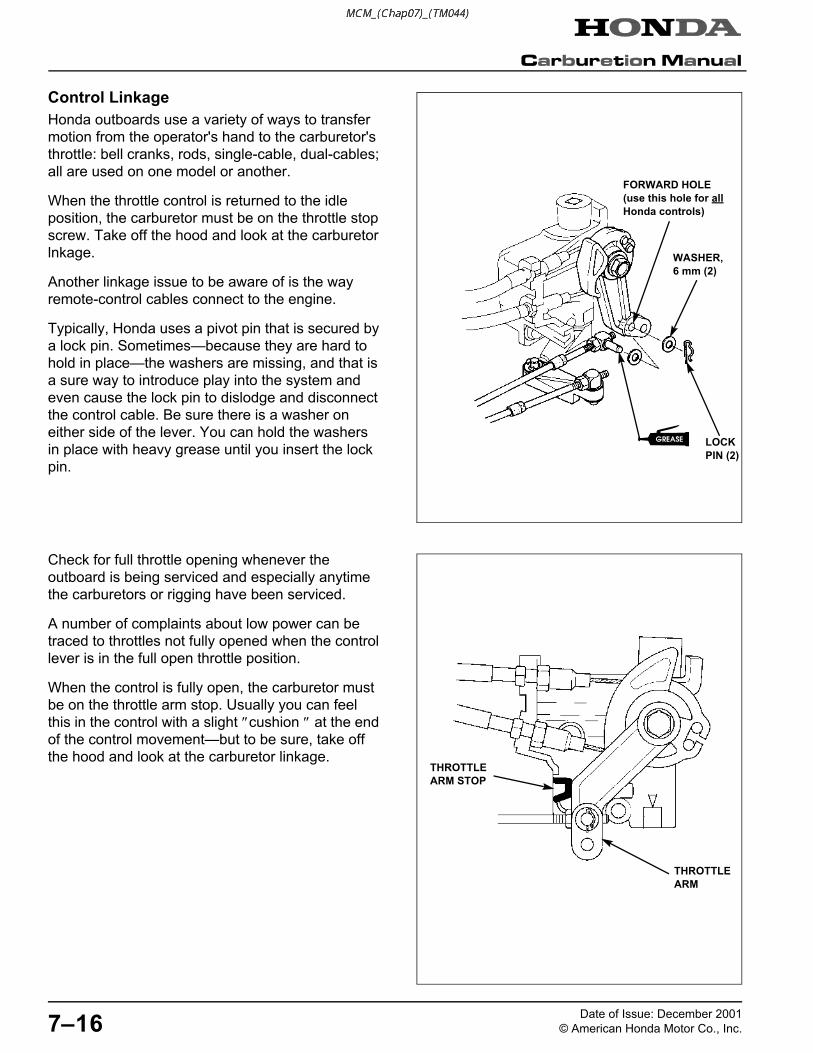
Control Linkage
Honda outboards use a variety of ways to transfer
motion from the operator's hand to the carburetor's
throttle: bell cranks, rods, single-cable, dual-cables;
all are used on one model or another.
When the throttle control is returned to the idle
position, the carburetor must be on the throttle stop
screw. Take off the hood and look at the carburetor
lnkage.
Another linkage issue to be aware of is the way
remote-control cables connect to the engine.
Typically, Honda uses a pivot pin that is secured by
a lock pin. Sometimes—because they are hard to
hold in place—the washers are missing, and that is
a sure way to introduce play into the system and
even cause the lock pin to dislodge and disconnect
the control cable. Be sure there is a washer on
either side of the lever. You can hold the washers
in place with heavy grease until you insert the lock
pin.
Check for full throttle opening whenever the
outboard is being serviced and especially anytime
the carburetors or rigging have been serviced.
A number of complaints about low power can be
traced to throttles not fully opened when the control
lever is in the full open throttle position.
When the control is fully open, the carburetor must
be on the throttle arm stop. Usually you can feel
this in the control with a slight ″cushion ″ at the end
of the control movement—but to be sure, take off
the hood and look at the carburetor linkage.
LOCK
PIN (2)
WASHER,
6 mm (2)
�
FORWARD HOLE
(use this hole for all
Honda controls)
THROTTLE
ARM
THROTTLE
ARM STOP
me-carb.book Page 16 Sunday, December 9, 2001 5:12 PM