g section vi carburetion - vintage snog ." section vi carburetion contents of this section...
TRANSCRIPT

G
."
SECTION VI
CARBURETION
Contents of this Section
Condensed Data (1972 through 1987)
Systems ...
Component Effect VS Throttle Opening.
Component Functions. . . . . .
Jetting Guidelines and Part Numbers
1979 Jetting Compensation for Altitude/Temperature
1980 Jetting Compensation for Altitude/Temperature
1981 Jetting Compensation for Altitude/Temperature
1982 Jetting Compensation for Altitude/Temperature
1983 Jetting Compensation for Altitude/Temperatu re
1984 Jetting Compensation for Altitude/Temperature
1985 Jetting Compensation for Altitude/Temperature
1986 Jetting Compensation for Altitude/Temperature
1987 Jetting Compensation for Altitude/Temperature
Main Jet Number VS Fuel Flow and Carburetor Identification
Exploded View - VM26SS
Adjustments - Jetting.
Problem Diagnosis
Adjustments
Adjustments - Choke
Adjustments - Jet Needle and Float Level
Overhaul Service
Fuel Pump ..
1 - 5h
6-9
10
11 - 13
14
15 -17
17a - 17c
17d - 17e
17f - 17g
17h - 17i
17j - 17k
17/ - 17m
17n - 170
17p - 17q
18
19
20
21 - 22
23
24
25
26 - 27
28 - 29
5/86

o
(

)
1 9 7 2
1 9 7 3
Engine
Model
EC17P
EC25P
EC29P
EC29PF
~
EC34PS
EC40P
EC40PF
EC51PS
EC54P
EC54PF
EC17P
EC25PS
EC29PM
EC29PF
EC29PS
EC34PF
EC34PS
EC40PM
EC40PS
EC44PS
EC51PS
EC54PM
No. Carb. Size of Type and
Cyl. Number
1 VM24SH (1)
1 VM30SH (1)
2 VM26SH (2)
2 VM26SH (2)
2 VM26SS (2)
2 VM30SH (2)
2 VM30SH (2)
3 VM26SH (3)
2 VM32SH (2)
2 VM32SH (2)
1 VM24SH (1)
1 VM30SH (1)
2 VM26SH (2)
2 VM26SH (2)
2 VM30SS (2)
2 VM26SH (2)
2 VM30SS (2)
2 VM30SH (2)
2 VM32SS (2)
2 VM32SS (2)
3 VM30SS (3)
2 VM32SS (2)
Jet Needle No. Throttle
"E" Cl ip Needle Valve
Position Jets Cutaway
---- --- --
6DH4-3 0-8 3.0
5DP7-3 0 - 8 3.0
5DP7-3 0 - 8 3.0
5DP7-3 0 - 8 3.0
5DP7- 3 0 - 8 3.0
5DP7- 3 0-8 3.0
5DP7-3 0 - 8 3.0
5DH4-3 0 - 8 2.0
5DH4-3 0-8 2.0
5DP7-3 P-4 2.0
5DT7- 4 0 - 8 3.0
5DP7-3 0-8 3.0
5DP7-3 0 - 8 3.0
5DP7- 3 P- 2 3.0
5DP7- 3 0 - 8 3.0
5DP7-3 P-2 3.0
5DP7-3 0-8 3.0
5DH4- 3 0 -8 2.0
5DH4-3 0-8 2.0
5DP7- 3 0 - 8 3.0
5DH4-3 0-8 2.0
VI-1
CARBURETION
Condensed Data
Original Recommended Recommended
Jetting Je'tting/O'.5,OOO' Jetting/5,OOO'·10,OOO'
Main Pilot Main Pilot Main Pilot . 300H 40 - - - 35 --- - - --
125 40 120 35 115 35
107.5 40 --- 35 105 35
107.5 40 --- 35 105 35
125 40 120 35 105 35
120 40 - -- 35 110 35
120 40 - -- 35 110 35
125 40 120 35 11 5 35
140 40 132.5 35 125 35
140 40 132.5 35 125 35
102.5 40 --- 35 --- ---
125 40 120 35 115 35
110 40 --- 35 100 35
115 40 110 35 100 35
127.5 40 120 35 105 35
115 40 110 35 107.5 35
127.5 40 120 35 110 35
120 40 --- 35 117.5 35
145 40 132.5 35 120 35
145 40 137.5 35 120 35
127.5 40 120 35 115 35
145 40 132.5 35 125 35
3/81

CARBURETION
Condensed Data
1 9 7 4
1 9 7 5
3/81
No. Carbo Size Jet Needle No. Engine of Type and "E" Clip Model Cyl. Number Position
EC17PM 1 VM24SH (1) 5DP7-3
EC25PS 1 VM30SH (1) 5DP7- 4
EC25PC 2 VM26SS (2) 5DP7- 3
EC25PT 2 VM30SS (2) 5DP7-3
EC29PF 2 VM26SH (2) 5DP7-3
EC34PC 2 VM26SH (2) 5DP7- 3
EC34PQ 2 VM32SS (1) 5DP10-4
EC34PS 2 VM30SS (2) 5DP7- 3
EC40PM 2 VM30SH (2 ) 5DP7-3
EC44PQ 2 VM3SSS (1) 5DP7-3
EC44PT 2 VM3SSS (2) 6DH4-4
EC51PT 3 VM32SS (3) 6DH4- 4
EC54PM 2 VM32SS (2) 5DH4-3
•
EC17PM 1 VM24SH (1) 5DP7-3
EC25PS 1 VM30SH (1) 5DP7-4
EC25PC 2 VM26SS (2) 5DP7- 3
EC25PT 2 VM30SS (2) 5DP7-3
EC34PC 2 VM26SS (2) 5DP7-3
EC34PQ 2 VM30SS (2) 5DP10-4
EC34PT 2 VM32SS (2) 6DH4-3
,
EC44PQ 2 VM30SS (2) 5DP7-3
EC44PT 2 VM3SSS (2) 6DH4-4
EC51PT 3 VM32SS (3) 6DH4- 5
C 1 2 3
With air silencer installed Reference Service Bulletin No. 93 Reference Service Bulletin No. 96 Reference Service Bulletin No. 101
Throttle Needle Valve
Jets Cutaway
P-4(212) 2.0
0-S(171) 3.0
0-S(164) 3.0
P-2(171) 3.0
O-S 3.0
0 - S(1 64) 3.0
P-2(171) 2.0
P-2 3.0
O-S 3.0
P-2(171) 3.0
Q-0(205) 1.5
0 - S(1SS) 2.5
O- S 2.0
P-4 2.0
O- S 3.0
O- S 3.0
O-S 3.0
O- S 3.0
P- 2 2.0
P-O 2.0
P-2 3.0
Q-O 1.5
0 - 2 2.5
VI-2
Original Recommended Recommended Jetting Jetti ng/O' -5,000' Jetting/5,000'-10,000'
Main Pilot Main Pilot Main Pilot
102.5 35 --- --- --- ---
125 35 120 --- 115 35
110 35 --- --- 100 35
125 35 115 --- 105 35
11 5 35 110 --- 107.5 35
125 35 112.5 --- 110 35
125 40 120 35C 107.5 35C )
127.5 35 120 --- 110 35
120 40 - -- 35 115 35
135 40 --- 35C 117.5 35C
135 35 --- __ C1 115 35C1
117.5 35 --- __ C 110 35C
145 40 130 35C 117.5 35C
( 102.5 35 - -- --- --- - --
125 35 117.5 __ C
11 5 35C
105 35 112.52 __ C 95 35C
120 35 --- --C 112.5 35C
112.5 35 107.5 --C3 100 35C3
122.5 30 117.5 --C 110 30C
140 30 130 --C 115 35C
125 25 115 --C 110 25C
140 40 132.5 45C 120 40C
120 40 - -- __ C 115 40C

'"' . ~
f) , I
~
1 9 7 6
1 9 7 7
I'
No. Carbo Size Engine of Type and Model Cyl. Number
EC17PM 1 VM24SH (1)
EC25PS 1 VM30SH (1)
EC25PC 2 VM26SS (2)
EC25PT·06 2 VM32SS (2)
EC25PT·05 2 VM32SS (2)
EC34PC 2 VM26SS (2)
EC34PO 2 VM30SS (2)
EC34PT·05 2 VM32SS (2)
EC34PT·06 2 VM34SS (2)
EC44PO 2 VM30SS (2)
EC44PT·05 2 VM34SS (2)
EC25PS 1 VM30SH (1)
EC25PC 2 VM26SS (2)
EC25PM·Ol 2 VM26SS (2)
EC25PT·07 2 VM30SS (2)
EC34PM·03 2 VM26SS (2)
EC34PO 2 VM30SS (2)
EC34PT·05 2 VM32SS (2)
EC34PL·Ol 2 VM38SS (2)
EC44PO 2 VM30SS (2)
EC44PT·05 2 VM34SS (2)
EC44PT·06 2 VM34SS (2)
With air silencer installed Hex head
Jet Needle No. "E" Clip
\',.;f?sition
5DP7- 3
5DP7-4
5DP30- 3 or 5DP7- 5
6DP1-3
6DPl - 3
5DP30-3 or 5DP7- 5
5DP10-4
6DPl-3
6DH4-3
5DP7-3
6DPl-3
5DP7-4
5DP7-5 or 5DP3-3
5DP7-2
5DP7-3
5DP7-2
5DP10-4
SDH7-3
6DH4-3
5DP7-3
6DPl-3
6DPl-3
C H 4 Lower "En clip to No.4 position
Needle Jets
, .. P-4(212)
0 - 8(171)
0 -8(164)
P-4(159)
P-2(159)
0-8(164)
P-2(171 )
P-4(159)
0-0(159)
P- 2(171)
P- 6(166)
0-8(171)
0 - 8(164)
0-8
P-2(171)
0-8
P-2(171)
P-4(159)
0-2(166)
P-2(17~)
P-6(166)
P-6(166)
VI-3
CARBURETION
Condensed Data
Throttle Original Recommended Recommended Valve Jetting Jetting/0'·5,000' Jetting/5,000'·10,000'
Cutaway Main Pilot Main Pilot Ma in Pilot
2.0 102.5 35 --- --- --- ---
3.0 125 35 117.5 __ C
115 35C
3.0 112.5 35 --- __ C 95 35C
2.0 260H 30 --- 35C 190H 30C
2.0 230H 35 --- __ C --- --C
3.0 107.5 35 --- __ C ·105 35C
2.0 122.5 30 117.5 __ C
110 30C
2.0 270H 30 260H4 __ C
230 30C
1.5 270H 30 --- __ C --- __ C
3.0 125 25 115 --C 115 25C
2.5 320H 35 --- __ C 270 35C
3.0 117.5 35 --- __ C REFER TO THE
3.0 112.5 35 --- __ C 1977 SHOP MANUAL
/
2.5 130H 35 --- __ C FOR SPECIFIC
2.5 220H 35 --- __ C ALTITUDE
2.5 150H 35 130H __ C
TEMPERATURE
2.0 122.5 30 117.5 __ C
COMPENSATION
2.0 280H 30 270H __ C
ADJUSTMENTS
2.5 340H 45 320H4 __ C ,.
3.0 115 25 --- __ C
", , 2.5 320H 35 - -- _ _ C
2.5 320H 35 --- _ _ C
- ., . "";;;;
3/81

CARBURETION
Condensed Data
1 9 7 8
Machine Model
Colt
Col t
SIS 340
Cobra
Cobra
TX
TX
TX
TX-L
Engine Model
EC25PS
EC25PC
EC34PM- 03 EC34PM-04N
EC34PM-04
EC44PM-01
EC25PT -07
EC34PT -05
EC44PT - 05
EC34PL- 02
Engine Model
EC25PS
EC25PC
EC34PM-03
EC34PM-04N
EC34PM- 04
EC44PM-01
EC25PT -07
EC34PT-05
EC44PT - 05
EC34PL-02
Cyl. Carburetor
Oisp. Model, Mount CC's Type & No.
VM30SH (1)
244 Flange
VM26SS (2)
250 Rubber
VM26SS (2)
333 Rubber
VM26SS (2)
333 Rubber
VM34SS (2)
432 Rubber
VM30SS (2)
249 Rubber
VM32SS (2)
336 Rubber
VM34SS (2)
432 Rubber
VM38SS (2)
333 Rubber
Jet Needle No. "E" Clip Needle Position Jets
50P7 - 4 0 - 8 (171)
50P7 - 5 or 50P3 - 3 0 - 8 (164)
50P7 - 2 0 - 8 (259)
5EP6 - 3 P- 2 (259)
50P7 - 3 P-2 (259)
60P1 - 3 P-6 (166)
50P7 - 3 P- 2 (171 )
60H7 - 3 P- 4 (1 59)
60H7 - 3 P-6 (166)
60H4 -3 0-2 (247)
Air Screw Std. Std. Adjust.
Main Jet Pilot (counterclock wise & Type Jet from seat)
117.5 Round 35 1 turn
112.5 Round 35 1 turn
130 1 turn Hex 35 1/2 turn
130 Hex 35 1 turn
200 Hex 35 1 turn
220 Hex 35 1 turn
280
Hex 30 1 turn
370 Hex 45 1 turn
310 Hex 45 1 turn
Throttle Valve Valve Fuel
Cutaway Seat ' Mixture
3.0
3.0
2.5
3.0
3.0 1.5MM 40: 1
2.5
2.5
2.0
2.5
2.5
REFER TO THE 1978 SHOP MANUAL FOR SPECIFIC ALTITUDE/TEMPERATURE COMPENSATION ADJUST
MENTS.
3/81 VI-4

1 9 7 9
Machine
Model
Gemini
Gemini
Apollo
Cobra
Cobra
TX
TX
T X
T X-L
Centurion
Cyl. Carburetor
Engine Oisp. Model, Mount
Model CC's Type & No.
VM30SH (1)
EC25PS 244 Flange
VM26SS (2)
EC25PM- 01 244 Rubber
VM26SS (2)
EC34PM- 03 333 Rubber
VM26SS (2)
EC34PM-04 333 Rubber
VM34SS (2)
EC44PM- 01 432 Rubber
VM30SS (2)
EC25PT -07 249 Rubber
VM32SS (2)
EC34PT - 05 336 Rubber
VM34SS (2) i
EC44PT- 05 432 Rubber
VM38SS (2)
EC34PL-02 333 Ru bber
VM34SS (3) EC51PL- 01 500 Rubber
Jet Needle No.
Engine " E" Clip Needle Model Pos ition Jets
EC25PS 50P7 - 4 0-8 ( 177)
EC25PM- 01 50P7 - 2 0 - 8
EC34PM- 03 50P7 - 2 0-8
EC34PM- 04 50T49 - 2* P- 2 (259)
EC44PM-01 60P1 - 3 P- 6 (166) -
EC25PT -07 50P7 - 3 P-2 ( 171 )
EC34PT - 05 60H7 - 2 P-4 (159)
EC44PT - 05 60H7 - 2 0-0 (166)
EC34PL-02 60H4 - 3 0-2 (247)
EC51PL- 01 60H7 - 2 0-2 (166)
* Reference Information Bulletin No. 1-78-5
VI-5
CARBURETION
Condensed Data
Air Screw
Std. Std. Adjust.
Main Jet Pilot (cou nt erclockwise
& Type Jet from seat )
117.5
Round 35 1 turn
120
Hex 35 1 turn
130
Hex 35 1 turn
130
Hex 35 1 turn
200 Hex 35 1 t urn
220
Hex 35 1 tu rn
290
Hex 30 1 tu rn
320
Hex 30 1 turn
260
Hex 45 1 turn
220
Hex 35 1 1/2 turn
Thrott le
Valve Valve Fuel Cutaway Seat Mi xture
3.0
2. 5
2.5
3.0
2.5 1.5MM 40: 1
2. 5
2. 0
2.5
2.5
3. 0

CARBURETION
Condensed Data
1 9 8 o
Machine Model
Gemini
Gemini
Apollo
Galaxy
Galaxy
TX/TX-C
TX
TX-L/TX-L Indy
Centurion
Engine Model
EC25PS
EC25PM-01
EC34PM-03
EC34PM-04
EC44PM - 01/02
EC34PT -07
EC44PT -05
EC34PL-02/05
EC51PL- 02
Engine Model
EC25PS
EC25PM- 01
EC34PM-03
EC34PM- 04
EC44PM - 01 /02
EC34PT -07
EC44PT-05
EC34PL- 02/05
EC51 PL- 02
Cyl. Carburetor Disp. Model, Mount CC's Type & No.
VM30SS (1)
244 Rubber
VM26SS (2) 244 Rubber
VM26SS(2)
333 Rubber
VM26SS (2)
333 Rubber
VM34SS(2)
432 Rubber
VM32SS (2)
336 Rubber
VM34SS(2)
432 Rubber
VM38SS(2)
333 Rubber
VM34SS (3)
500 Rubber
Jet Needle No. "E" Clip Needle Position Jets
5DT49- 2 0 - 8 (177)
5DP7 - 2 0-8
5DP7 - 2 0 - 8
5DT49-2 P-2 (259)
6DP1 - 3 P-6 (166)
6DH7 - 2 P-4 (159)
6DH7 - 2 0-0 (166)
6DH4 - 3 0-2 (247)
6DH7 - 2 0 - 2 (166)
VI- Sa
Air Screw
Std. Std. Adjust.
Main Jet Pilot (cou nterclockwise
& Type Jet from seat)
120 Hex 60 1 turn
120 Hex 35 1 turn
130 Hex 35 1 turn
110
Hex 35 1 turn
200 Hex 35 1 turn
280 Hex 30 1 turn
320 Hex 30 1 turn
260
Hex 45 1 turn
220 Hex 35 11/2turn
Throttle
Valve Valve Fuel Cutaway Seat Mixture
3.0
2.5
2.5
3.0 1.5MM 40: 1
2.5
2.0
25
2.5
3.0
(

(
( )
Machine Model
Gemini
Galaxy
Cutlass
Cutlass SS
TX-C
TX-l/TX-L Indy
Centurion Indy
1 9 8 1
Engine Model
EC25PS
EC44PM-02
EC34PM-03
EC44-2PM-
3100/3300
EC44- 2PM -
1100
EC34PL- 05
EC51PL-02
Engine Model
EC25PS
EC44PM-02
EC34PM-03
EC44-2PM-
3100/3300
EC44-2PM-1100
EC34PL-05
EC51PL-02
Cyl. Carburetor Disp. Model, Mount CC's Type & No.
VM30SS (1)
244 Rubber
VM34SS (2)
432 Rubber
VM26SS (2)
333 Rubber
VM38SS (1)
432 Rubber
VM34SS (2)
432 Rubber
VM38SS (2)
333 Rubber
VM34SS (3)
500 Rubber
Jet Needle No. "E" Clip Needle Position Jets
5DT49-2 0-8 (177)
6DP1-3 P-6 (166)
5DP7-3 0-8 (259)
6DH7-3 0 - 2 (247)
6DH7-3 P-6 (166)
6DH4-3 0-2 (247)
6DH7-2 0-2 (166)
VI- 5b
CARBURETION
Condensed Data
Air Screw
Std. Std. Adjust. Main Jet Pilot (cou nterclockwise & Type Jet from seat)
120 Hex 60 1 turn
200 Hex 35 1 turn
130 Hex 30 1 turn
290 Hex 40 1 turn
270 Hex 35 1 turn
260 Hex 45 1 turn
220 Hex 35 1 1/2 turn
Throttle Valve Valve Fuel
Cutaway Seat Mixture
3.0 1.5mm 40:1
2.5 1.5mm 40:1
2.5 1.5mm 40:1
Variable Ratio/ 2.0 1.5mm Automatic
Injection
Variable Ratio/ 3.5 1.5mm Automatic
Injection
2.5 1.5mm 40:1
3.0 1.5mm 40:1

CARBURETION
Condensed Data
1 9 8 2
Machine Model
Cutlass SS
TX·C
TX-L/TX-l Indy
Centurion Indy
Engine Model
EC44-2PM-3100*1
EC44-2PM-3100*2
EC44- 2PM-1100
EC34Pl-05
EC51Pl-02
Cyl. Engine Disp. Model CC's
EC44-2PM-3100*1 432
EC44-2PM-3100*2 432
EC44-2PM-
1100 432
EC34Pl-05 333
EC51PL-02 500
Jet Needle No. "E" Clip Needle Position Jets
60H7-3 0-2 (247)
6DH7-3 P-6 (166)
6DH7-3 P-6 (166)
6DH4-3 0 -2 (247)
6DH7-2 0-2 (166)
*1 *2
Engine serial numbers beginning with 80-Engine serial numbers beginning with 81-
Carburetor Std. Model, Mount Main Jet
Type & No. & Type
VM38SS(1) 290 Rubber Hex
VM34SS(1) 280 Rubber Hex
VM34SS(2) 270 Rubber Hex
VM38SS(2) 260 Rubber Hex
VM34SS(3) 220 Rubber Hex
Throttle Throttle Valve Valve
Cutaway Spring PN
2.0 7041136
2.5 3130289
3.5 3130026
2.5 3130026
3.0 3130026
3/81 VI - 5c
Air Screw Std. Adjust. Pilot (counterclockwise Jet from seat)
40 1 turn
40 1 turn
35 1 turn
45 1 turn
35 1 1/2 turn
Valve Fuel Seat Mixture
Variable Ratio/ 1.5mm Automatic
Injection
Variable Ratio/ 1.5mm Automatic
Injection
Variable Ratio/ 1.5mm Automatic
Injection
1.5mm 40:1
1.5mm 40:1

1 ) 9
)
8 3
Machine Engine
Model Model
Gemini /Star EC25PS
EC44-2PM Sport 5100
EC44-2PM SS 3100
EC44-2PM Indy Trail 2100
Indy Cross Country EC34PL-05
-
Indy 600 EC60PL-Ol
EC44-2PM Long Track 5000
Jet Needle No.
Engine "E"Clip
Model Position
EC25PS 5DT49-3
EC44-2PM-
5100 5DP10-3
EC44-2PM·
3100 6DH7-3
EC44-2PM-
2100 6DH7·2
EC34PL·05 6DH4-3
EC60PL ·Ol 6DH4-3
EC44-2PM -
5000 5DP10-3
CARBURETION
Condensed Data
Air Screw Cyl. Carburetor Std . Std . Adjust.
Disp. Model, Mount Main Jet Pilot (counterclockwise CC's Type & No. & Type Jet from seat)
VM30SS(1 ) 130 244 Zinc Hex 60 1 1/2 turn
VM30SS(1) 190 432 Zinc Hex 35 1.0 turn
VM34SS(1) 280 432 Zinc Hex 40 1.0 turn
VM34SS(2) 230 432 Zinc Hex 35 1.0 turn
VM38SS(2) 260 333 Alum Hex 40 1.0 turn
VM38SS(3) 250 597 Alum Hex 40 1.0 turn
VM30SS(1) 190 432 Zinc 35 1.0 turn
Throttle Throttle
Needle Valve Valve Valve Fuel
Jets Cutaway Spring PN Seat Mixture
0-8 (171) 3.0 3130281 1.5mm 40:1
Variable Ratio/ P-8 (171) 2.5 3130281 1.5mm Automatic
Injection
Variable Ratio/ P- 6 (166) 2.5 3130289 1.5mm Automatic
Injection
Variable Ratio/
P- 6 (166) 3.0 3130026 1.5mm Oil
Injection
0 - 2 (247) 2.5 3130026 1.5mm 40 :1
0 - 2 (247) 3.5 3130026 1.5mm 40:1
P-8 (171) 2.5 3130281 1.5mm 40:1
VI - 5 d 5/82

CARBURETION
Condensed Data
1 9 8 4
5/83
Machine Model
Star/Star L T
SS
Indy Trail
Indy 600
Long Track
Engine Model
EC25PS-05
EC44-2PM-3100
EC44-2PM-
2100
EC60PL-02
EC44-2PM-
5000
Cyl. Engine Disp. Model CC's
EC25PS-05 244
EC44-2PM 3100 432
EC44-2PM
2100 432
EC60PL-02 597
EC44-2PM
5000 432
Jet Needle No. "E" Clip Needle Position Jets
5DT49-3 0-8 (171)
6DH7-3 P-6 (166)
6DH7-2 P-6 (166)
6F4-3 Q-2 (247)
5DP10-3 P-8 (171)
I I Air Screw
Carburetor Std. Std. Adjust Model, Mount Main Jet Pilot (counterclockwise
Type & No. & Type Jet from seat )
VM30SS(1) 130 Zinc Hex 60 1 1/2 turn
VM34SS(1) 280 Zinc Hex 40 1.0 turn
VM34SS(2) 230 Zinc Hex 35 1.0 turn
VM38SS(3) 250 Alum Hex 40 1.0 turn
VM30SS(1 )
Zinc 200 30 1.0 turn
Throttle Throttle Valve Valve Valve Fuel
Cutaway Spring PN Seat Mixture
3.0 3130281 1.5mm 40:1
Variable Ratio/ 2.5 3130289 1.5mm Automatic
Injection
Variable Ratio/ 3.0 3130026 1.5mm Oil
Injection
Variable Ratio/ 3.5 3130314 1.5mm Oil
Injection
2.5 3130281 1.5mm 40:1
VI-5e

G
1 () 9
8 5
c
c
Machine Model
Star
SS
Indy Trail
Indy 400
Indy 600
Long Track
Engine Model
EC25PS-06
EC44-2PM-
3100
EC44·2PM-
2100
EC40PL·02
EC60PL-02
EC44-2PM-
5000
Engine
Model
EC25PS·06
EC44-2PM
3100
EC44·2PM
2100
EC40PL-02
EC60PL·02
EC44·2PM 5000
Jet Needle No. "E" Clip
Position
5DT49·3
6DH7·3
6DH7·2
6DH7-2
6F4-3
5DP10-3
CARBURETION
Condensed Data
Air Screw
Cyl. Carburetor Std. Std. Adjust
Disp. Model, Mount Main Jet Pilot (counterclockwise
CC's Type & No. & Type Jet from seat)
VM30SS(1) 130
244 Zinc Hex 60 11/2turn
VM34SS(1) 280
432 Zinc Hex 40 1.0 turn
VM34SS(2) 230 432 Zinc Hex 35 1.0 turn
VM34SS(2) 220 398 Zinc Hex 35 1.0 turn
VM38SS(3) 260 597 Alum Hex 35 3/4 turn
VM30SS(1 ) 200 432 Zinc Hex 30 1.0 turn
Throttle Throttle
Needle Valve Valve Valve Fuel Idle Jets Cutaway Spring PN Seat Mixture RPM
Variable Ratio/ 0-8(171) 3.0 3130281 1.5mm Automatic 2100
Injection
Variable Ratio/ P-6 (166) 2.5 3130289 1.5mm Automatic 2300
Injection
Variable Ratio/ P- 6 (166) 3.0 3130314 1.5mm Automatic 2300
Injection
Variable Ratio / P- 8 (1 66 ) 3.0 3130314 1.5mm Automatic 2200
Injection
Variable Ratio/ P-8 (247) 3.0 3130334 1.5mm Automatic 2000
Injection
P- 8 (171) 2.5 3130281 1.5mm 40:1 2300
VI-5f 5/85

CARBURETION
Condensed Data
1 9 8 6
5/85
Machine Model
Star
Sprint (ES )
SS
Indy Trail
Indy 400
Indy 600 (LE)
Long Track
Engine Model
EC25PS-06
EC34-2PM 01/02
EC44-2PM-3100
EC50PM-Ol
EC40PL-02
EC60PL-02
EC44-2PM-5100
Cyl. Engine Disp. Model CC's
EC25PS-06 244
EC34-2PM 01/02 339
EC44-2PM 3100 432
EC50PM-Ol 488
EC40PL-02 398
EC60PL-02 597
EC44-2PM 5100 432
Jet Needle No. HE" Clip Needle Position Jets
5DT49-3 0-8 (171)
5DP7-3 0-8 (171)
6DH7·3 P-6 (166)
6DH7-2 P-8 (166)
6DP17-2 0-2 (166)
6F9-3 P-8 (247)
5DP10-3 P-8(171)
Air Screw
Carburetor Std. Std. Adjust
Model, Mount Main Jet Pilot (counterclockw ise o Type & No. & Type Jet from seat)
VM30SS (1) 130 Zinc Hex 60 1 1/2 turn
VM30SS(2 ) 145 Zinc Hex 35 1.0 turn
VM34SS (1) 280 Zinc Hex 40 1.0 t urn
(
VM34SS(2 ) 210 Zinc Hex 30 1.0 t urn
VM34SS(2) 220 Zinc Hex 30 1.0 turn
VM38SS(3) 260 A lum Hex 35 3/4 turn
VM30SS(1) 200 Zinc Hex 30 1.0 turn
(
Throttle Throttle Valve Valve Valve Idle Fuel/Oil
Cutaway Spring PN Seat RPM Mixture
Variable Ratio/ 3.0 3130281 1.5mm 2100 Automatic
Injection
Variable Ratio/ 3.0 3130350 1.5mm 2100 Automatic
Injection
Variable Ratio/ 2.5 3130318 1.5mm 2300 Automatic
Injection
Variable Ratio/ 3.0 3130318 1.5mm 2000 Automatic
Injection
Variable Ratio/ 2.0 3130318 1.5mm 2200 Automatic
Injection
Variable Ratio/ 3.0 3130334 1.5mm 2000 Automatic
Injection
Variable Ratio/ 2.5 3130281 1.5mm 2300 Automatic
Injection
VI - 5g

J
(
(
1 9 8 7
Machine Model
Star, Star Trak
Sprint (ES)
Indy Sport
Indy Trail (All)
Indy 400
Indy 600
Long Track (R.L.R .)
Engine Model
EC25PS-06
EC34-2PM-01/02
EC34-2PM· 03
EC50PM-01
EC40PL-02
EC60PL-02
EC44-2PM-5100
Engine Model
EC25PS-06
EC34-2PM-01/02
EC34·2PM-03
EC50PM-01/02
EC40PL-02
EC60PL-02
EC44-2PM-5100
Jet Needle No. "E" Clip
Position
5DT49-3
5DP7-3
5DP7-3
6DH7-3
6DP17-3
6F9-3
5DP10-3
CARBURETION
Condensed Data
Air Screw
Cyl. Carburetor Std. Std. Adjust
Disp. Model, Mount Main Jet Pilot (counterclockwise
CC's Type & No. & Type Jet from seat)
VM30SS(1) 130 244 Zinc Hex 60 11/2 turn
VM30SS(2) 155 339 Zinc Hex 35 1.0 turn
VM30SS(2) 180 339 Zinc Hex 35 1.0 turn I ·
VM34SS(2) 220 488 Zinc Hex 30 1.0 turn
VM34SS(2) 220 398 Zinc Hex 30 1 1/2 turn
VM38SS(3) 260 597 Alum Hex 40 1.0 turn
VM30SS(1) 200 432 Zinc Hex 30 1.0 turn
Throttle Throttle Idle Needle Valve Valve Valve RPM Fuel /Oil
Jets Cutaway Spring PN . Seat ~ 200 Mixture
Variable Ratio/ 0 - 8 (171 ) 3.0 3130281 1.5mm 2100 Automatic
Injection
V ari able Ratio / .0- 8 (171 ) 3.0 3130350 1.5mm 2100 Automatic
Injection
Variable Ratio/ 0 - 8 (171 ) 3.0 3130350 1.5mm 2100 Automatic
Injection
Variable Ratio/ P-8 (1 66) 3.0 3130318 1.5mm 1900 Automat ic
Injection
Variable Ratio/ 0 -2 (166) 2.0 3130318 1.5mm 1900 Automatic
Injection
Variable Ratio/ P-8 (247) 3.0 3130334 1.5mm 1900 Automatic
Injection
Variable Ratio/ P-S (171) 2.5 3130281 1.5mm 2300 Automatic
Injection
VI-5h 5/86

I ,

o

CARBURETION
Systems
FUNCTION OF A CARBURETOR
The function of a carburetor is to produce combustible air-fuel mixture, by breaking fuel into tiny particles (in the form of vapor) and by mixing the fuel with air in a proper ratio, and to deliver the mixture to the engine. A proper ratio (mixture ratio or air·fuel ratio) means an ideal air-fuel mixture that can burn without leaving an excess of fuel or air. Whether the proper mixture ratio is maintained or not holds the key to the efficient engine operation.
FUNCTIONS AND CONSTRUCTION
The engine of a vehicle is operated under a wide range of conditions, from idling with the throttle valve remaining almost closed to the full load (the maximum output) with the throttle valve fully opened. In order to meet the requirements for the proper mixture ratio under these varying conditions, a low-speed fuel system (the pilot system) and a main fuel system (the main system) are provided in Mikuni VM-type carburetors.
The Mikuni carburetor has varying operations depending upon varying driving conditions. It is constructed with the float system, the pilot system, the main system, and the starter system (initial starting device).
FLOAT SYSTEM - No.1
The float system is designed to maintain a constant height of gasoline during operation. When the fuel flowing from the fuel pump into the float chamber through the needle valve reaches the constant fuel level, the floats rise. When the buoyancy of the float and the fuel pressure of the fuel pump balance, the needle valve sticks fast to the needle seat preventing further delivery of gasoline, thereby holding the standard level of gasoline. The fuel level in the bowl controls the amount of fuel in the fuel mixture. Too high a level allows more fuel than necessary to leave the nozzle , enriching trie mixture. Too Iowa level results in a leaner mixture, as not enough fuel leaves the nozzle. Therefore, the predetermined fuel level should not be changed arbitrarily.
FLOIT
VI-6
(
)

ST ARTER SYSTEM - No. 2
CARBURETION
Systems
Starting device (starter system) -In the place of the choke, the starter system is employed for Mikuni carburetors. In the starter type, fuel and air for starting the engine are metered with entirely independent jets. The fue l metered in the starter jet is mixed with air and is broken into tiny particles in the emu lsion tube. The mixture then flows into the plunger area, mixes again with air coming from the air intake port for starting and is delivered to the engine in the optimum air-fuel ratio through the fuel discharge nozzle. The starter is opened and closed by means of the starter plunger. Since the starter type is constructed so as to utilize the negative pressure of the inlet pipe, it is important that the throttle valve is closed when starting the engine.
TltOlllE vim
flU 01Tl1T
Wttq~~~;:;:;~~-SIUTlt I IiLSIOI lUll
IILIT ' IlIlD III
VI-7
".
CARBU RETION
Systems
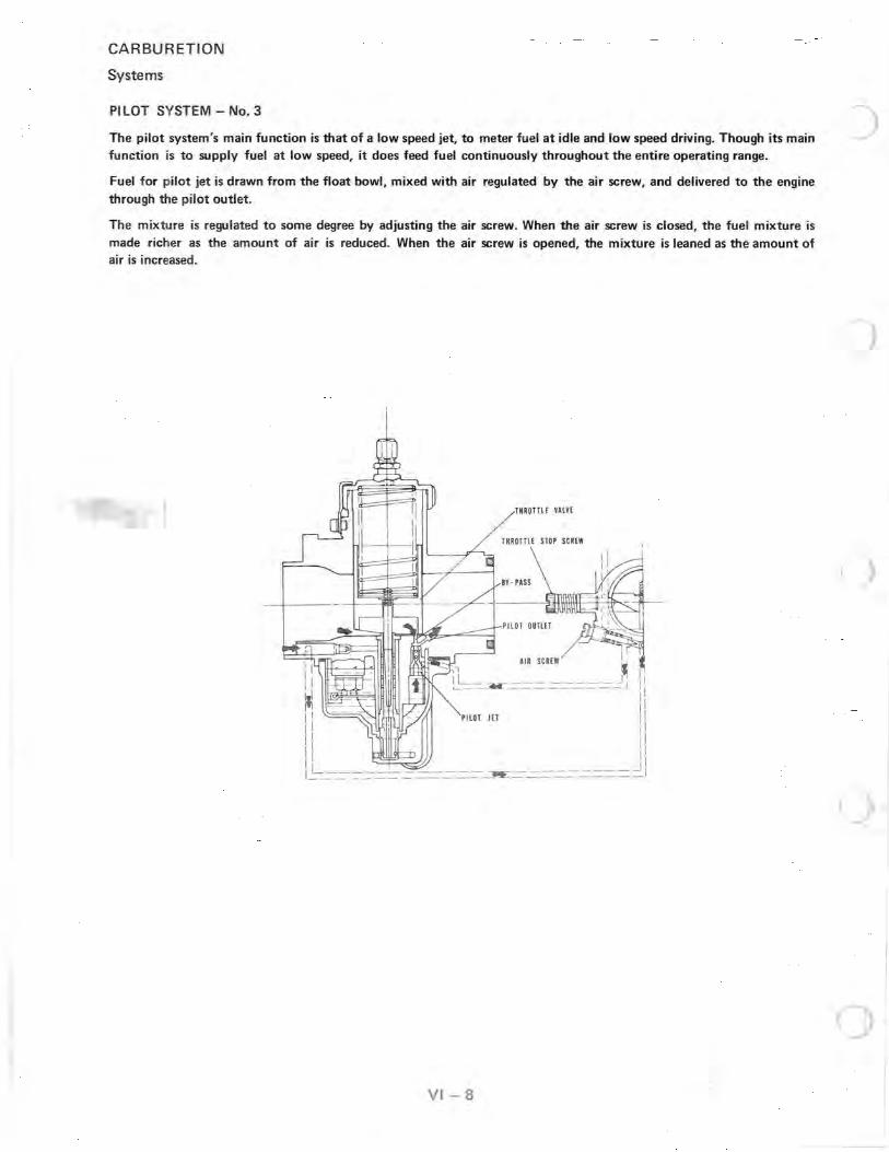
PILOT SYSTEM - No.3
The pilot system's main function is that of a low speed jet, to meter fuel at idle and low speed driving. Though its main function is to supply fuel at low speed, it does feed fuel continuously throughout the entire operating range.
Fuel for pilot jet is drawn from the float bowl, mixed with air regulated by the air screw, and delivered to the engine through the pilot outlet.
The mixture is regulated to some degree by adjusting the air screw. When the air screw is closed, the fuel mixture is made richer as the amount of air is reduced. When the air screw is opened, the mixture is leaned as the amount of air is increased.
THROTTL[ VALV[
IIR SCREW ~ If o ~ ~ II __ ~ __ -------IJ II ~--~--------- I
I PILOT lET I
I I
II :: I~ _---=--=--=--=-=--=---=---=--=--=--=---=:!I'£: - -=--=--=--=--=-= = = =- 1
VI-8
)

MAIN SYSTEM - No.4
CARBURETION
Systems
The main system is designed for delivering fuel between low speed and high speed operation. This system is made up of the jet needle, needle jet, and main jet. The main system begins to take effect as soon as there is enough air flow into the carburetor venturi to draw fuel up through the main jet and needle jet assembly.
During low-speed driving there is very little clearance between the jet needle and the needle jet; therefore, very little fuel from the main jet can pass between the jet needle and the needle jet. As the throttle valve opening is .increased, the tapered jet needle is raised farther out of the needle jet, allowing greater fuel flow. Under full throttle opening, the cross-sectioned area of clearance between the jet needle and the needle jet becomes greater than the cross-sectioned area of the main jet. Thus the main jet is now controlling the amount of fuel flow.
THROTTLE VALVE
JET NEEDLE
AIR JET BY • PASS
PILOT OUTLET
PILOT JET
NEEDLE JET
JET
VI-9

CARBURETION
Component Effect VS Throttle Opening
EFFECT
I I
I I
I I
I , I
o 1/8 1/4 3/8 1/2
THROTTLE - - - - - THROTTLE VALVE CUT-AWAY - -JET NEEDLE/NEEDLE JET
5/8 3/4 7/8 FULL
OPENING
The preceding throttle opening chart demonstrates component relationship to fuel flow versus throttle valve opening.
Pilot System
The pilot system's main function is that of a low speed jet. Its most effective range of fuel delivery is from idle to approximately 3/8 throttle valve opening.
- - - - - - - - Throttle Valve Cutaway
The throttle valve controls the rate of engine air by its movement up and down in the carburetor venturi. At small throttle openings the air flow is regulated chiefly by the valve cutaway as shown, with its greatest effectiveness at 1/4 throttle opening. Throttle valves are number 1.0, 1.5, 2.0, etc., according to the size of the cutaway. Decreasing the cutaway number will increase the amount of fuel delivered in its effective range.
- -- -- -- Jet Needle/Needle Jet
The jet needle and needle jet have an effective operating range from approximately 1/8 to 7/8 throttle opening. The amount of fuel delivered during this range relies upon the jet needle clip position, as well as the needle jet size and other specifications.
--------- Main Jet
The main jet affects fuel delivery at 1/4 throttle and consistently increases to full throttle opening.
VI-l0
)

PILOT JET From idling to low speeds, the fuel supply is measured out chiefly by the pilot jet. In the sides of the pilot jet, there are several air bleed openings which serve the same purpose as the air bleed in the needle jet, that is, to reduce the fuel to mist. The number stamped on the jet is an indication of the amount of fuel in cc's which passes through the jet during a one minute interval under a given set of cond itions.
PILOT AIR SCREW This air screw controls the mixture from idling to low speeds. The tapered tip of the air screw projects into the air passage leading to the pilot jet air bleeds, and by turning the screw in or out, the crosssectional area of the air passage is varied, in turn varying the pilot jet air supply and changing the mixture ratio.
VI - 11
CARBURETION
Component Functions
• <

CARBURETION
Component Functions
JET NEEDLE
The jet needle has 5 grooves for adjustment cut in the upper portion, and is tapered from approximately the middle of the needle to the lower end. The top is fixed to the center of the throttle valve by the needle clip, and the tapered end extends into the needle jet. Fuel flows through the space between the needle jet and jet needle, which space is unvary ing until the throttle reaches the 1/4 open point. At this time the tapered portion of the needle begins to move out of the jet and affect fuel flow as the opening enlarges. It follows that taper wear, and the position of the needle clip in the grooves also affect fuel flow rate. If the needle clip is changed from the standard position to a lower groove, the needle taper starts coming out of the jet sooner, resulting in a richer mixture; moving the clip higher produces a leaner mixture.
NEEDLE JET
The needle jet works in conjunction with the jet needle to regulate fuel flow rate. In the side of the needle jet, there is an air bleed opening which brings in air measured by the air jet. This air initiates the mixing and atomizing process inside the needle jet, and mixing is augmented by a projection at the needle jet outlet, called the primary choke. The letter number code stamped on the jet indicates jet inside diameter.
THROTTLE OPENING VS FUEL FLOW
In the full throttle condition, the cross-sectioned area between the jet needle and the needle jet is larger than the cross-sectioned area of the main jet; therefore, the main jet has greater control over fuel flow.
VI - 12
Closed Throttle
1
3 Groove
5
I =1==
I
A
One·half Throttle
Leaner
1 Richer
Full Throttle
larte Clearalce
)
)
oJ
()
o
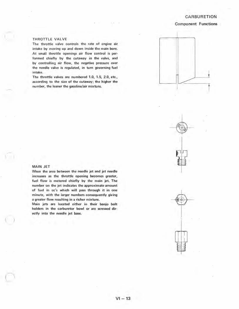
THROTTLE VALVE The throttle valve controls the rate of engine air intake by moving up and down inside the main bore. At small throttle openings air flow control is per
formed chiefly by the cutaway in the valve, and by controlling air flow , the negative pressure over the needle valve is regulated, in turn governing fuel intake. The throttle valves are numbered 1.0, 1.5, 2.0, etc., according to the size of the cutaway; the higher the number, the leaner the gasoline/air mixture.
MAIN JET When the area between the needle jet and jet needle
increases as the throttle opening becomes greater, fuel flow is metered chiefly by the main jet. The number on the jet indicates the approximate amount of fuel in cc's which will pass through it in one minute, with the larger numbers consequently giving a greater flow resulting in a richer mixture. Main jets are located either in their banjo bolt holders in the carburetor bowl or are screwed directly into the needle jet base.
VI-13
CARBUR ETION
Component Functions

CARBURETION
Jetting Guidelines and Part Numbers
The number o'f the main jet is stamped on each jet. The jet size is also stamped on the banjo bolt, but NEVER
assume that this is correct, al'Nays remove the banjo bolt and check the main jet itself.
The original main jet is not necessarily the correct main jet for that particular engine or altitude.
NOTE: Each engine has sligh,ly different characteristics, therefore, two engines of one particular cc may not nec
essarily be jetted exactly the same.
Pilot jets are instrumental in low RPM performance. If the fuel flow is too great at low RPM, the excess fuel will build up in the crankcase, and only JVith increased RPM will the fuel be transferred to the combustion chamber.
CAUTION: TOO SMALL A MAIN JET AND TOO SMALL A PILOT JET CAN CAUSE SERIOUS ENGINE DAMAGE. JET THE CAR~URETORS CAREFULLY.
IT IS THE DEALER'S RESPONSIBILITY TO INSURE THAT THE CORRECT JETS ARE INSTALLED IN A
MACHINE. BE VERY CAREFUL WHEN JETTING DOWN IN WARM WEATHER; AS THE WEATHER TURNS
COLDER IT WILL BE NE:CESSARY TO REJET UPWARD TO PREVENT ENGINE DAMAGE.
The following chart lists all main and pilot jets and the part number of each that are presently available.
ROUND HEAD HEX HEAD PI LOT JET NO. PART NO. MAIN JET NO. PART NO. MAIN JET NO. PART NO.
25 3130064 160 3130094 210 3130124 30 3130065 165 3130095 220 3130125 35 3130066 170 3130096 230 3130126 40 3130067 175 3130097 240 3130127 45 3130068 180 3130098 250 3130128 50 3130069 HEX HEAD 260 3130129 55 3130070 MAIN JET NO. PART NO. 270 3130130 60 3130071 80 3130099 280 3130131 65 3130072 85 3130000 290 3130132
ROUND HEAD 90 3130101 300 3130133 MAIN JET NO. PART NO. 95 3130102 310 3130134 ---
90 3130073 100 3130103 320 3130135 95 3130074 105 3130104 330 3130136 100 3130075 110 3130105 340 3130137 102.5 3130076 115 3130106 350 3130138 105 3130077 120 3130107 360 3130139 107.5 3130078 125 3130108 380 3130140 110 3130079 130 3130109 400 3130141 112.5 3130080 135 3130110 420 3130142 115 3130081 140 3130111 430 3130143 117.5 3130082 145 3130112 440 3130144 120 3130083 150 3130113 450 3130145 122.5 3130084 155 3130114 460 3130146 125 3130085 160 3130115 470 3130147 127.5 3130086 165 3130116 490 3130148 130 3130087 170 3130117 500 3130149 132.5 3130088 175 3130118 530 3130150 135 3130089 180 3130119 560 3130151 137.5 3130090 185 3130120 590 3130152 140 3130091 190 3130121 620 3130153 145 3130092 195 3130122 150 3130093 200 3130123
VI-14
)
( ) -

c
)
)
(J
Ma ximum engine efficiency and horsepower are directly related to proper carburetion settings. The following charts are established as a guideline for selecting optimum jetting at varying temperature and altitude conditions for the 1979 Polaris.
IMPORTANT: The following gu idelines must be followed when establish ing a main jet setting:
CA RBURETION
1979 Jetting Compensation for Altitude/Temperat ure
EC25PS
1000
]13000 u..
I ~5000 :::l .... . ;:;
-40
122.5
120
11 5
Outside Air Temperature 0 F
- 20 0 +20 +40 +60
120 117.5 115 11 2.5 110
117.5 11 5 112.5 110 107.5
11 5 112.5 110 107.5 105
1. Select the lowest anticipated temperature at <{ 7000 which the machine wi ll be operated.
112.5 11 0 11 0 107.5 105 102.5
2.
3.
1 9 7 9
....
Determine the lowest approximate altit ude at which th e machine will be operated.
Tracing down and across on the chart, use the intersecting ma in jet recommendation.
-40
1000 130
EC25PM-Ol Outside Air Temperature 0 F
-20 0 +20 +40
120 120 120 110
~ 3000 120 120 110 110 110
I
~ 5000 120 110 110 100 100 :::l .... . ;:;
<{ 7000 110 100 100 100 90
9000 100 100 90 90 90
Main Jet Number
9000
+60
110
100
90
90
80
110 107.5 107.5 105 102.5 100
Main Jet Number
Pilot Jet - 35 Production Setting Main Jet - 117.5 Cut Away - 3.0 Air Screw - 1.0 turn Jet Needle - 5DP7-4
EC34PM- 03 Outside Air Temperature 0 F
-40 - 20 0 +20 +40
140 140 130 130 120
130 130 120 120 110
130 120 120 120 110
120 120 110 110 100
110 110 100 100 90
Main J.et Number
Production Setting
+60
110
110
100
100
90
Production Setting Main Jet - 120 Cut Away - 2.5
Pilot Jet - 35 Main Jet - 130 Pilot Jet - 35 Air Screw - 1.0 turn Cut Away - 2.5 Air Screw - 1.0 turn
Jet Needle - 5DP7-2 Jet Needle - 5DP7-2
VI - 15

CARBURETION
1979 Jetting Compensation for Altitude/Temperature
EC34PM-04
1000
~ 3000 ~ u.
I ~ 5000
"0 ::l .... . ~ <t 7000
9000
1 9 7 9
1000
~ 3000 ~
u.
~ 5000 "0 ::l .~
~ 7000
9000
Outside Air Temperature 0 F
-40 -20 0 +20 +40 +60
140 130 120 120 110 110
130 120 120 110 110 100
120 110 110 110 100 100
110 110 100 100 100 90
110 100 100 90 90 90
Main Jet Number
Production Setting Main Jet - 130 Pilot Jet - 35 Cut Away - 3.0 Air Screw - 1.0 turn Jet Needle - 50T49-2* *Reference Information Bulletin No. 1-78- 5
-40
230
220
200
190
180
EC25PT -07 Outside Air Temperature 0 F
-20 0 +20 +40
220 210 200 190
210 200 190 180
200 190 180 170
180 180 170 160
170 170 160 150
Main Jet Number
+60
180
170
160
150
140
EC44PM-Ol
Outside Air Temperature 0 F
-40 -20 0 +20 +40 +60
210 200 190 180 180 170
200 190 180 170 170 160
190 180 170 160 160 150
170 170 160 150 150 140
160 160 150 140 140 130
Main Jet Number
Pilot Jet - 35 Production Setting Ma in Jet - 200 Cut Away - 2.5 Air Screw - 1.0 turn Jet Needle - 60Pl - 3
EC34PT -05 Outside Air Temperature 0 F
-40 - 20 0 +20 +40 +60
310 300 290 280 270 260
300 290 280 270 260 240
280 270 260 250 240 230
260 250 240 240 230 220
250 240 230 220 210 200
Mai n Jet Number
Production Setting Production Setting Main Jet - 220 Cut Away - 2.5
Pilot Jet - 35 Ma in Jet - 290 Pi lot Jet - 30 Air Screw - 1.0 turn Cut Away - 2.0 Air Screw - 1.0 turn
Jet Need le - 50P7-3 Jet Need le - 60 H7-2
VI -1 6
(
(

)
1000
~ 3000 u.. I
Q) 5000 " :::I ... . '::; « 7000
9000
1 9 7 9
1000
'Q; 3000 Q)
u.. I
Q) 5000
" :::I :!:: ... « 7000
9000
EC44PT-05 Outside Air Temperature 0 F
CARBURETION
1979 Jetting Compensation for Altitude/ Temperature
EC34PL-02
-40 -20 0 +20 +40 +60
340 330 320 310 300 280
330 310 300 290 280 270
310 300 290 280 260 250
290 280 270 260 250 240
270 260 250 240 230 220
Main Jet Number
Pilot Jet - 30 Production Setting Main Jet - 320 Cut Away - 2.5 Air Screw - 1.0 turn Jet Needle - 6D H7-2
EC51PL- 01 Outside Air Temperature 0 F
- 40 -20 0 +20 +40 +60
240 230 220 210 210 200
220 220 210 200 200 190
210 200 200 190 190 180
200 190 180 180 180 170
190 180 170 170 170 160
Main Jet Number
Production Setting Main Jet - 220 Cut Away - 3.0
Pilot Jet - 35 Air Screw - 1.5 turn
Jet Needle - 6DH7-2
VI-17
Outside Air Temperature 0 F
- 40 - 20 0 +20 +40 +60
280 270 260 250 240 230
270 260 250 240 230 220
250 240 230 220 220 200
240 230 220 210 200 190
220 210 200 200 190 180
Main Jet Number
Pilot Jet - 45 Production Setting Main Jet - 260 Cut Away - 2.5 Air Screw - 1.0 turn Jet Need le - 6D H4-3

CARBURETION
1980 Jetting Compensation for Altitude/Temperature
Maximum engine efficiency and horsepower are directly related to proper carburetion settings. The following charts are established as a guideline for selecting optimum jetting at varying temperature and altitude conditions for the 1980 Polaris.
IMPORT ANT: The following guidelines must be followed when establishing a main jet setting:
1. Select the lowest anticipated temperature at which the machine will be operated.
2. Determine the lowest approximate altitude at which the machine will be operated.
3. Tracing down and across on the chart, use the intersecting main jet recommendation.
1 9 8 o
1000
i3000 LL.
~ 5000 :::l ... . ';:;
~ 7000
9000
- 40
130
120
120
110
100
EC25PM-Ol
Outside Air Temperature 0 F
-20 0 +20 +40
120 120 120 110
120 110 110 110
110 110 100 100
100 100 100 90
100 90 90 90
Main Jet Number
1000
~ 3000 (1)
LL.
~ 5000 "0 :::l ... . ';:; <t 7000
9000
+60
110
100
90
90
80
Production Setting Main Jet - 120 Cut Away - 2.5
Pilot Jet - 35 Air Screw - 1.0 turn
Jet Needle - 5DP7- 2
VI - 17a
EC25PS
Outside Air Temperature of
-30 - 10 +10 +30 +50
125 120 115 110 105
120 115 110 105 100
110 105 100 100 95
105 100 95 95 90
100 95 90 85 85
Main Jet Number
Pilot Jet - 60 Production Setting Main Jet - 120 Cut Away - 3.0 Air Screw - 1.0 turn Jet Needle - 5DT49-2
-40
140
130
130
120
110
EC34PM-03 Outside Air Temperature 0 F
- 20 0 +20 +40
140 130 130 120
130 120 120 110
120 120 120 110
120 110 110 100
110 100 100 90
Main Jet Number
Pilot Jet - 35
+60
110
110
100
100
90
Production Setting Main Jet - 130 Cut Away - 2.5 Air Screw - 1.0 turn Jet Needle - 5DP7-2
)
(

(
c
1000
t; 3000 Q)
u.. I
Q) 5000 "0
::::1 ... ... « 7000
9000
1 9 8 o 1000
~ 3000 Q)
u.. I
Q) 5000 "0
::::1 ... . ;; « 7000
9000
EC34PM- 04 Outside Air Temperatu re 0 F
CARBURETI ON
1980 Jetting Compensation for Altitude/Temperature
EC44PM-Ol/02
-30 -10 +10 +30 +50
115 110 105 100 95
110 105 100 95 90
105 100 95 90 85
95 95 90 85 80
90 85 85 80 80
Main J et Number
Production Setting Main Jet - 110 Cut Away - 3.0 Jet Needle - 5DT49-3
Pilot J et - 35 Air Screw - 1.0 turn
EC34PT -07 Outside Air Temperature 0 F
-30 -10 +10 +30 +50
290 280 270 260 250
280 270 260 250 230
260 250 240 230 220
250 240 230 220 210
230 220 210 200 195
Main Jet Number
Production Setting Main Jet - 280 Cut Away - 2.0 Jet Needle - 6DH7-2
Pilot Jet - 30 Air Screw - 1.0 turn
VI-17b
Outside Air Temperature 0 F
-40 - 20 0 +20 +40 +60
210 200 190 180 180 170
200 190 180 170 170 160
190 180 170 160 160 150
170 170 160 150 150 140
160 160 150 140 140 130
Main Jet Number
Pilot Jet - 35 Production Setting Main Jet - 200 Cut Away - 2.5 Air Screw - 1.0 turn Jet Needle - 6DPl - 3
EC44PT-05 Outside Air Temperature 0 F
-40 -20 0 +20 +40 +60
340 330 320 310 300 280
330 310 300 290 280 270
310 300 290 280 260 250
290 280 270 260 250 240
270 260 250 240 230 220
Main Jet Number
Pilot Jet - 30
Production Setting Main Jet - 320 Cut Away - 2.5 Air Screw - 1.0 turn Jet Needle - 6DH7-2

CARBURETION
1980 Jetting Compensation f or Altitude/Temperature
EC34PL-02/05
1000
* 3000 u.. I
Q) 5000 "C
::::I ... . ~ « 7000
9000
1 9 8 o
./
Outside Air Temperature 0 F
-40 -20 0 +20 +40 +60
280 270 260 250 240 230
270 260 250 240 230 220
250 240 230 220 220 200
240 230 220 210 200 190
220 210 200 200 190 180
Main Jet Number
Production Setting Main Jet - 260 Cut Away - 2.5 Jet Needle - 6D H4- 3
>' Pilot Jet ~'··45
Air Screw - 1.0 turn
VI - 17e
EC51PL-02 Outside Air Temperature 0 F
-40 - 20 0 +20 +40 +60
240 230 , 220 210 210 200
220 220 210 200 200 190
210 200 200 190 190 180
200 190 180 180 180 170
190 180 170 170 170 160
Main Jet Number
Pilot Jet - 35 Production Setting Main Jet - 220 Cut Away - 3.0 Air Screw - 1.5 turn Jet Needle - 6DH7-2
)

c
CARBURETION
1981 Jetting Compensation for Altitude/Temperature
EC25PS
Maximum engine efficiency and horsepower are directly related to proper carburetion settings. The
following charts are established as a guideline for selecting optimum jetting at varying temperature and altitude conditions for the 1981 Polaris.
IMPORT ANT: The following guidelines must be followed when establishing a main jet setting:
1. Select the lowest anticipated temperature at which the machine will be operated.
2. Determine the lowest approximate altitude at which the machine will be operated.
3. Tracing down and across on the chart, use the intersecting main jet recommendation.
1 9 8 1
1000
~ 3000 u.
~ 5000 :l
.'.:: ... ~ 7000
9000
- 40
210
200
190
170
160
EC44PM-02 Outside Air Temperature 0 F
-20 0 +20 +40
200 190 180 180
190 180 170 170
180 170 160 160
170 160 150 150
160 150 140 140
Main Jet Number
1000
~ 3000 Q)
u.
~ 5000 -0 :l
.~ ... ~ 7000
9000
+60
170
160
150
140
130
Production Setting Main Jet - 200 Cut Away - 2.5
Pilot Jet - 35 Air Screw - 1.0 turn
Jet Needle - 6DPl-3
VI - 17d
Outside Air Temperature 0 F
-30 -10 +10 +30 +50
125 120 115 110 105
120 115 110 105 100
110 105 100 100 95
105 100 95 95 90
100 95 90 85 85
Main Jet Number
Pilot Jet - 60 Production Setting Main Jet - 120 Cut Away - 3.0 Air Screw - 1.0 turn Jet Needle - 5DT49-2
-40
135
130
120
115
105
EC34PM- 03 Outside Air Temperatu re 0 F
- 20 0 +20 +40
130 125 120 115
125 120 115 110
115 110 105 105
110 105 100 95
105 100 95 90
Main Jet Number
Pilot Jet - 30
+60
110
105
100
90
85
Production Setting Main Jet - 130 Cut Away - 2.5 Air Screw - 1.0 turn Jet Needle - 5DP7-3

CARBUR ETION
1981 Jetting Compensation for Altitude/Temperature
1000
il 3000 u..
I Ql 5000
"t:l :J .... . ;; « 7000
9000
1 9 8 1 1000
il 3000 u..
I '" 5000
"t:l :J .'= .... « 7000
9000
- 40
310
300
280
260
250
EC44- 2PM-31 00/3300
Outside Ai r Temperature a F
- 20 0 +20 +40
300 290 280 270
290 280 270 260
270 260 250 240
250 240 240 230
240 230 220 210
Main Jet Number
Pilot Jet - 40
+60
260
240
230
220
200
Production Setting Main Jet - 290 Cut Away -- 2.0 Air Screw - 1.0 turn Jet Needle - 60H7-3
-40
280
270
250
240
220
EC34PL-05 Outside Air Temperature 0 F
-20 0 +20 +40
270 260 250 240
260 250 240 230
240 230 220 220
230 220 210 200
210 200 200 190
Main Jet Number
+60
230
220
200
190
180
Production Setting Main Jet - 260 Cut Away - 2.5
Pilot Jet - 45 Air Screw - 1.0 turn
Jet Needle - 60 H4- 3
VI - 17e
- 40
280
270
250
240
220
E C44-2PM -1100 Outside Air Temperature 0 F
- 20 0 +20 +40
270 260 250 240
260 250 240 230
240 230 220 220
230 220 210 200
210 200 200 190
Main Jet Number
Pilot Jet - 35
+60
230
220
200
190
180
Production Setting Main Jet - 270 Cut Away - 3.5 Air Screw - 1.0 turn Jet Needle - 60H7-3
EC51 PL-02 Outside Air Temperature 0 F
-40 - 20 0 +20 +40
240 230 220 210 210
220 220 210 200 200
210 200 200 190 190
200 190 180 180 180
i 190 180 170 170 170
Main Jet Number
Pilot J et - 35
+60
200
190
180
170
160
Production Setting Main Jet - 220 Cut Away - 3.0 Air Screw - 1.5 turn Jet Needle - 60H7-2
)
(

c
)
1000
~ 3000 u.. I '" 5000
"t:l "::J .... . .:;
<! 7000
9000
1 9 8 2 1000
~ 3000 Q)
u..
I Q) 5000
"t:l ::J
.'.:: .... ~ 7000
9000
CARBURETION
1982 Jetting Compensation for Altitude/Temperature EC44-2PM-3100
(With Engine Serial Numbers Beginning 80-) Outside Air Temperature 0 F
-40 -20 0 +20 +40 +60
310 300 290 280 270 260
300 290 280 270 260 240
280 270 260 250 240 230
260 250 240 240 230 220
250 240 230 220 210 200
Main Jet Number
Pilot Jet - 40
Production Setting Main Jet - 290 Cut Away -- 2.0 Air Screw - 1.0 turn Jet Needle - 60H7-3
- 40
280
270
250
240
220
EC44-2PM-1100 Outside Air Temperature 0 F
- 20 0 +20 +40
270 260 250 240
260 250 240 230
240 230 220 220
230 220 210 200
210 200 200 190
Main Jet Number
Pilot Jet - 35
+60
230
220
200
190
180
Production Setting Main Jet - 270 Cut AVJay - 3.5 Air Screw - 1.0 turn Jet Needle - 60H7-3
VI - 17f
EC44-2PM-3100 (With Engine Serial Numbers Beginning 81-)
Outside Air Temperature 0 F
-40 -20 0 +20 +40
290 280 270 260 250
280 270 250 240 230
260 250 240 230 220
250 240 230 220 210
230 220 210 200 190
Mam Jet Number
Production Setting Main Jet - 280 Pilot Jet - 40 Cut Away - 2.5 Air Screw - 1.0 turn Jet Needle - 60H7-3
-40
280
270
250
240
220
EC34P L-05 Outside Air Temperatu re 0 F
- 20 0 +20 +40
270 260 250 240
260 250 240 230
240 230 220 220
230 220 210 200
210 200 200 190
Main Jet Num ber
Pilot J et - 45
+60
240
220
210
200
180
+60
230
220
200
190
180
Production Setting Main Jet - 260 Cut Away - 2.5 Air Screw - 1.0 tu rn Jet Needle - 60 H4-3
3/81

CARBURETION
1982 Jetting Compensation for Al t itude/Temperature
EC51PL- 02
1000
i 3000 u..
I C1l 5000
"tl :::s ... . ;; <i 7000
9000
1 9 8 2
3/81
Outside Air Temperature 0 F
-40 -20 0 +20 +40 +60
240 230 220 210 210 200
220 220 210 200 200 190
210 200 200 190 190 180
200 190 180 180 180 170
190 180 170 170 170 160
Main Jet Number
Production Setting Main Jet - 220 Cut Away - 3.0 Jet Needle - 6DH7-2
Pilot Jet - 35 Air Screw - 1.5 turn
VI -17g
)
)
()

c
1000
~ 3000 u..
I Ql 5000 -0 :J ... ...
<{ 7000
1 9 8 3
9000
1000
~ 3000 u..
I Q) 5000 -0 :J ... ...
<{ 7000
9000
CARBURETION
1983 Jetting Compensation for Altitude/Temperature
- 40
240
230
220
210
200
EC44-2PM-2100 Outside Air Temperature 0 F
- 20 0 +20 +40
230 230 220 210
220 220 210 200
210 210 200 190
200 200 190 180
190 190 180 170
Main Jet Number
Pilot Jet - 35
+60
200
190
180
170
170
Production Setting Main Jet - 230 . Cut Away - 3.0 Air Screw - 1.0 turn Jet Needle - 6DH7- 2
EC25PS Outside Air Temperature 0 F
·-40 -20 0 +20 +40 +60
130 130 120 120 110 110
130 120 120 110 100 100
120 110 110 100 100 90
110 110 100 100 90 90
110 100 100 90 90 80
Main Jet Number
Pilot Jet - 60
-40
290
280
260
250
230
EC44-2PM-3100 Outside Ai r Temperature 0 F
- 20 0 +20 +40
280 270 260 250
270 250 240 230
250 240 230 220
240 230 220 210
220 210 200 190
Main Jet Number
Production Setting Main Jet - 280 Pilot Jet - 40 Cut Away - 2.5 Air Screw - 1.0 turn Jet Needle - 6DH7- 3
-40
200
190
180
170
160
EC44-2PM - 5000/5100 Outside Air Temperature 0 F
-20 0 +20 +40
190 190 180 170
180 180 180 170
170 170 160 160
160 160 150 150
150 150 140 140
Main Jet Number
Pilot Jet - 35
+60
240
220
210
200
180
+60
170
160
150
140
130
Production Setting Main Jet - 130 Cut Away - 3.0 Air Screw - 1.5 turn
Production Setting Main Jet - 190 Cut Away - 2.5 Air Screw - 1.0 turn
Jet Needle - 5DT49-3 Jet Needle - 5DP10- 3
VI - 17h 5/82

CARBURETI ON
1983 Jetting Compensation for Altitude/Temperature
EC34PL - 05 Outside Ai r T emperatu re 0 F
I I - 40 - 20 0 +20 +40 I +60 i
I !
I I I I .--j I
1 9 8 3
I I I , i
280 270 I 260 250 I 240 i 230 I ! ! I
~ 240 ~
230 220 270 260 250
!
I 250 240 I 230 I
220 i 220 I
200 I ! i
I
I I I 240 230 220 210 I
200 I 190
220 210 200 200 I 190 180 I I I Main Jet Number
Production Setting Main Jet - 260 Cut Away - 2.5 Jet Needle - 60 H4- 3
Pilot Jet - 40 Air Screw - 1.0 turn
NOTES
VI - 17i
EC60PL-01 Outside Air Temperature 0 F
- 40 - 20 0 +20 +40 +60
260 250 240 240 230 220
250 240 230 230 220 210
240 230 220 220 210 200
220 210 200 200 190 190
210 200 190 190 180 180
Main Jet Number
Pilot Jet - 40 Production Setting Main Jet - 250 Cut Away - 3.5 Air Screw - 1.0 turn Jet Needle - SOH4-3

c
c
1000
~ 3000 u. I
C1l 5000 "tJ :::l .... . ;:;
~ 7000
1 9 8 4
9000
1000
~ 3000 u. I
Q) 5000 "tJ :::l .~ .... ~ 7000
9000
CARBURETION
1984 Jetting Compensation for Altitude/Temperature
- 40
240
230
220
210
200
EC44- 2PM-2100 Outside Air Temperature 0 F
- 20 0 +20 +40
230 230 220 210
220 220 210 200
210 210 200 190
200 200 190 180
190 190 180 170
Main Jet Number
Pilot Jet - 35
+60
200
190
180
170
170
Production Setting Main Jet - 230 Cut Away - 3.0 Air Screw - 1.0 turn Jet Needle - 6DH7- 2
EC25PS-05 Outside Air Temperature 0 F
- 40 - 20 0 +20 +40 +60
130 130 120 120 110 110
130 120 120 110 100 100
120 110 110 100 100 90
110 110 100 100 90 90
110 100 100 90 90 80
Main Jet Number
Pilot Jet - 60
- 40
290
280
260
250
230
EC44- 2PM-3100 Outside Air Temperature 0 F
- 20 0 +20 +40
280 270 260 250
270 250 240 230
250 240 230 220
240 230 220 210
220 210 200 190
Main Jet Number
Production Setting Main Jet - 280 Cut Away - 2.5
Pilot Jet - 40 Air Screw - 1.0 turn
Jet Needle - 6DH7-3
- 40
200
190
180
170
160
E C44- 2PM-5000 Outside Air Temperature 0 F
- 20 0 +20 +40
190 190 180 170
180 180 180 170
170 170 160 160
160 160 150 150
150 150 140 140
Main Jet Number
Pilot Jet - 30
+60
240
220
210
200
180
+60
170
160
150
140
130
Production Setting Main Jet - 130 Cut Away - 3.0 Air Screw - 1.5 turn
Production Setting Main Jet - 200 Cut Away - 2.5 Air Screw - 1.0 turn
Jet Needle - 5DT49- 3 Jet Needle - 5DP10-3
VI - 17j 5/83

CARBURETION
1984 Jetting Compensation for Altitude/Temperature
1000
~ 3000 ~
I Q) 5000
-0 ::s
.'= .... « 7000
9000
1 9 8 4
- 40
260
250
240
220
210
EC60PL-02 Outside Air Temperature 0 F
- 20 0 +20 +40
250 240 240 230
240 230 230 220
230 220 220 210
210 200 200 190
200 190 190 180
Main Jet Number
Pilot Jet - 40
+60
220
210
200
190
180
Production Setting Main Jet - 250 Cut Away - 3.5 Air Screw - 1.0 turn Jet Needle - 6F4-3
NOTES
5/83 VI - 17k

(
1000
~ 3000 u.
I CIl 5000
"tJ :J .... . ;;
::t 7000
9000
1 9 8 5
1000
~ 3000 u.
I CIl 5000
"tJ :J .'= .... ::t 7000
9000
CARBURETION
1985 Jetting Compensation for Altitude/Temperature
I
-40
240
230
220
210
200
EC44-2PM-2100 Outside Air Temperature 0 F
- 20 0 +20 +40
230 230 220 210
220 220 210 200
210 210 200 190
200 200 190 180
190 190 180 170
Main Jet Number
Pilot Jet - 35
+60
200
190
180
170
170
Production Setting Main Jet - 230 Cut Away - 3.0 Air Screw - 1.0 turn Jet Needle - 6DH7-2
EC25PS-06 Outside Air Temperature 0 F
-40 -20 0 +20 +40 +60
130 130 120 120 110 110
130 120 120 110 100 100
120 110 110 100 100 90
110 110 100 100 90 90 I
i I
I I 80 I 110 100 100 90 90
_~ __ 1 I _'------1 -- -~
Main Jet Number
Production Setting Main Jet - 130 Cut Away - 3.0 Jet Needle - 5DT49-3
Pilot Jet - 60 Air Screw - 1.5 turn
- 40
290
280
260
250
230
EC44-2PM-3100 Outside Air Temperature 0 F
-20 0 +20 +40
280 270 260 250
270 250 240 230
250 240 230 220
240 230 220 210
220 210 200 190
Main Jet Number
Production Setting Main Jet - 280 Pilot Jet - 40 Cut Away - 2.5 Air Screw - 1.0 turn Jet Needle - 6DH7-3
-40
200
190
180
170
160 I
EC44-2PM-5000 Outside Air Temperature 0 F
- 20 0 +20 +40
190 190 180 170
180 180 180 170
170 170 160 160
160 160 I 150 150 I i
150 150 1
140 I 140 - _.-"-----
Main Jet Number
Pilot Jet - 30
+60
240
220
210
200
180
+60
170
160
150
140
1130 -
Production Settmg Main Jet - 200 Cut Away - 2.5 Air Screw - 1.0 t:Jrn Jet Needle - 5DP10-3
VI - 171 6/84

CARBURETION
1985 Jetting Compensation for Altitude/Temperature
1 9 8 5
6/84
... '" '" LL
I
'" "C ::l ... . ~ <i
... '" '" LL
I
'" "C ::l ... . ~ <i
-40--20
1000-3000 270
3000-5000 260
5000-7000 250
7000-9000 230
9000-11000 220
EC60PL- 02 Outside Air Temperature 0 F
-20- 0- +20-0 +20 +40
260 250 240
250 240 230
240 230 220
220 210 200
210 200 190
Main Jet Number
Pilot Jet - 35
+40-+60
230
220
210
190
180
Production Setting Main Jet - 260 Cut Away - 3.0 Jet Needle - 6F4-3
Air Screw - 3/4 Needle Jet - P8-247
-40--20
1000-3000 230
3000-5000 220
5000-7000 210
7000-9000 200
9000-11000 190
EC40PL-02 Outside Air Temperature 0 F
-20- 0- +20-0 +20 +40
220 220 210
210 210 200
200 200 190
190 190 180
180 180 170
Main Jet Number
Pilot Jet - 35
+40-+60
200
190
180
170
170
Production Setting Main Jet - 220 Cut Away - 3.0 Jet Needle - 6DH7-2
Air Screw - 1.0 Needle Jet - P8-166
VI-17m
)
)

n '-
C)
CARBURETION
1986 Jetting Compensation for Altitude/Temperature
-40--20
1000-3000 130
.... Q)
3000-5000 130 Q)
Ll-
Q) 5000-7000 120 " ::::1 .... .;:;
<i: 7000·9000 110
9000-11000 110
Star - EC25PS- 06 Outside Air Temperature 0 F
-20- 0- +20- +40-o +20 +40 +60
130 120 120 110
120 120 110 100
110 110 100 100
110 100 100 90
100 100 90 90
Main Jet Number
1 9 8 6
Production Setting Main Jet - 130 Cut Away - 3.0 Jet Needle - 5DT49-3
Pilot Jet - 60 Air Screw - 1.5 turn
SS - EC44-2PM-3100 Outside Air Temperature 0 F
-40- -20- 0- +20- +40-
.... Q) Q)
LI-
Q)
" ::::1 .... .;:;
<i:
-20
1000-3000 290
3000-5000 280
5000-7000 260
7000-9000 250
9000-11000 230
Production Setting Main Jet - 280 Cut Away - 2.5
o +20 +40 +60
280 270 260 250
270 250 240 230
250 240 230 220
240 230 220 210
220 210 200 190
Main Jet Number
Pilot Jet - 40 Air Screw - 1.0 turn
Jet Needle - 6DH7-3
VI - 17n
.... Q) Q)
u ..
Q)
" ::::1 <4 .;:;
<i:
... Q) Q)
LI-
I Q)
" ::::1 ... .;:;
<i:
Sprint (ES) - EC34-2PM-Ol/02 Outside Air Temperature 0 F
-40--20
1000-3000 150
3000-5000 145
5000-7000 140
7000-9000 135
9000-11000 130
Production Setting Main Jet - 145 Cut Away - 3.0
-20- 0- +20- +40-o +20 +40 +60
145 140 135 130
140 135 130 125
135 130 125 120
130 125 120 115
125 120 115 110
Main Jet Number
Pilot Jet - 35 Air Screw - 1.0 turn
Jet Needle - 5DP7 .. 3
Indy Trail - EC50PM-Ol Outside Air Temperature 0 F
-40--20
1000-3000 230
3000-5000 220
5000-7000 210
7000-9000 200
9000-11000 190
Production Setting Main Jet - 210 Cut Away - 3.0
-20- 0- +20- +40-o +20 +40 +60
220 210 200 190
210 200 190 180
200 190 180 170
190 180 170 160
180 170 160 160
Main Jet Number
Pilot Jet - 30 Air Screw - 1.0 turn
Jet Needle - 6DH7-2
5/85 (

CARBURETION
1986 Jetting Compensation for Altitude/Temperature
..... a.> 11>
LL.
11> -0 :I ..... .;:;
<i
1 9 8 6
Indy 400 - EC40PL-02 Outside Air Temperature 0 F
1000-3000
3000-5000
5000-7000
7000-9000
9000-11000
40--20
230
220
210
200
190
-20-o
220
210
200
190
180
0-+20
220
210
200
190
180
+20- +40-+40 +60
210 200
200 190
190 180
180 170
170 170
Main Jet Number
Production Setting Main Jet - 220 Cut Away - 2 .0 Jet Needle - 6DP17-2
Pilot Jet - 30 Air Screw - 1.0 turn
..... a.> 11>
LL.
a.> -0 :I ..... .;:;
<i
Indy 600 - EC60PL - 02 Outside Air Temperature 0 F
-40- -20- 0- +20- +40--20 0 +20 +40 +60
1000-3000 270
3000-5000 260
5000-7000 250
7000-9000 230
9000-11000 220
Production Setting Main Jet - 260 Cut Away - 3.0 Jet Needle - 6 F9-3
260 250 240 230
250 240 230 220
240 230 220 210
220 210 200 190
210 200 190 180
Main Jet Number
Pi lot Jet - 35 Air Screw - 3/4 t urn
Long Track - EC44- 2PM-5100 Outside Air Temperature 0 F
..... a.> a.>
LL.
I a.> -0 :I ..... . ;:; <i
40- -20--20 o
1000-3000 210 200
3000-5000 200 190
5000-7000 190 180
7000-9000 180 170
9000-11 000 170 160
0-+20
190
180
170
160
150
+20- +40-+40 +60
180 170
170 160
160 150
150 140
140 130
Main Jet Nu mber
Production Setting Main Jet - 200 Cut Away - 2.5 Jet Needle - 5DP10-3
Pilot Jet - 30 Air Screw - 1.0 turn Needle Jet - P8-171
5/85 VI - 170
(

c
C
1000-3000
.... '"
3000-5000
'" u..
'" 5000-7000 "0 :::l .... . ;:;
~ 7000-9000
9000-11000
Star Trak. Star - EC25PS-06 Outside Air Temperature 0 F
-40--20
130
130
120
110
110
-20-
o
130
120
110
110
100
0-+20
120
120
110
100
100
+20-+40
120
110
100
100
90
Main Jet Number
+40-
+60
110
100
100
90
90
1 9 8 7
Production Setting Main Jet - 130 Cut Away - 3.0 Jet Needle - 50T 49-3
Pilot Jet - 60 Air Screw - 1.5 turn
Long Track (R .L.R.) - EC44-2PM-5100 Outside Air Temperature 0 F
.... '" '" u..
'" "0 :::l .... .;;
~
-40--20
1000-3000 210
3000-5000 200
5000-7000 190
7000-9000 180
9000-11000 170
Production Setting Main Jet - 200 Cut Away - 2.5
-20- 0- +20- +40-o +20 +40 +60
200 190 180 170
190 180 170 160
180 170 160 150
170 160 150 140
160 150 140 130
Main Jet Number
Pilot Jet - 30
Jet Needle - 50Pl 0-3
Air Screw - 1.0 turn
Needle Jet - P8-171
CARBURETION
1987 Jetting Compensation for Altitude/Temperature
.... '" '" u..
'" "0 :::l
.!:: .... <t
... '" '" u..
'" "0 :::l .... .;;
~
Sprint (ES) - EC34-2PM-Ol/02 Outside Air Temperature 0 F
-40--20
1000-3000 160
3000-5000 155
5000-7000 145
7000-9000 135
9000-11000 130
-20-
o
155
150
140
130
120
0-+20
150
145
135
125
115
+20-+40
145
135
130
120
110
+40-
+60
140
130
125
115
105
Main Jet Number
Production Setting Main Jet - 155 Cut Away - 3.0 Jet Needle - 50P7-3
Pilot Jet - 35 Air Screw - 1.0 turn
Indy Sport - EC34-2PM-03 Outside Air Temperature 0 F
-40--20
1000-3000 190
3000-5000 180
5000-7000 170
7000-9000 160
9000-11000 150
-20-o
180
170
160
150
140
0-+20
170
160
150
140
130
+20- +40-+40 +60
160 160
160 150
150 140
140 130
130 125
Main Jet Number
Production Setting Main Jet - 180 Cut Away - 3.0 Jet Needle - 50P7-3
Pilot Jet - 35
Air Screw - 1.0 turn
VI - 17p 5/86

CARBURETION
1987 Jetting Compensation for Altitude/Temperature
.... Q) Q)
~
Q)
-0 ::I .... ";;
4:
1 9 8 7
.... Q) Q)
~
Q)
-0 ::I .... ";; 4:
1000-3000
3000-5000
5000-7000
7000-9000
9000-11000
Indy Trail (All) - EC50PM-Ol/02 Outside Air Temperature 0 F
-40-
-20
240
230
210
200
190
-20-o
230
220
210
190
180
0-+20
220
210
200
180
170
+20-+40
210
200
190
180
170
Main Jet Number
+40-+60
200
190
180
170
160
Production Setting Main Jet - 220 Cut Away - 3_0
Pilot Jet - 30 Air Screw - 1_0 turn
Jet Needle - 6DH7-3
1000-3000
3000-5000
5000-7000
7000-9000
Indy 600 - EC60PL-02 Outside Air Temperature 0 F
-40- -20- 0- +20- +40--20 0 +20 +40 +60
280 270 260 250 240
270 260 250 240 230
250 240 230 220 210
240 230 220 210 200
9000-11000 220 210 200 200 190
Production Setting Main Jet - 260 Cut Away - 3_0
Jet Needle - 6F9-3
Main Jet Number
Pilot Jet - 40 Air Screw - 3/4 turn
.... Q) Q)
~
I Q)
-0 ::I .... ";;
4:
-40-
-20
1000-3000 240
3000-5000 230
5000-7000 210
7000-9000 200
9000-11000 190
Indy 400 - EC40PL-02 Outside Air Temperature 0 F
-20-o
230
220
200
190
180
0-+20
220
210
200
190
170
+20-+40
210
200
190
180
160
Main Jet Number
Pilot Jet - 30
+40-+60
200
190
180
170
160
Production Setting Main Jet - 220 Cut Away - 2_0 Air Screw - 1 1/2 turn Jet Needle - 6DP17-3
NOTE: Main jet size on Indy 600 is li sted for PTO side (drive clutch side ) carburetor_ Magneto side and cente r carburetors can be adjusted one size leaner.
5/86 VI - 17q
J)
J
I
D
(

~) \ __ J
c)

CARBURETION
Main Jet Number VS Fuel Flow and Carburetor Identification
Main Jet Number VS Fuel Flow
Curves· M J No Verses Fuel Flow Quant ity . . ID 0
- II v -
1/ VV -
40 0
1/
p-
o ,
, ~ II I~~ I ,.,
II II
20 0
L!
II II
I,I'~
1-< V b'
I-"~
-
0 m in jet H. __ ---==50'---........ _ 100 150 200 250 !OO !50 400
Each Polaris engine has a carburetor that has been calibrated for certain characteristics and model design. The carburetor is stamped with the engine model designation on the carburetor body. Example: EC34PL-02 TX·L engine would have the designation 34L·02. The designation is usually stamped on the front side of the choke housing chamber.
VI-18
.(::i

METERI N G ROO ------------------
" E" C LIP ---------------------
THROTTLE VALVE ----------~
NEEOLE JET---------------
FUEL INLET BANJO BOlT- !
_ _ <0tb BANJO CONNECTOR .~
~
~, ~
/~, //./ """ '"''' ,,~"<? ":<; /' FLOAT ARM ·- - -~
NEEOLE VALVE ~ M A I N JET BAN JOB 0 L T __ - --- ti ,
M A I N JE T -------
VI-19
CARBURETION
Exploded View - VM26SS
PLUNGER CAP ASSEMBLY
STARTER PLUNGER
RUBBER MOUNT (SOME MODELS)
AIR AOJUSTMENT SCREW
PI L OT JET
NEEDLE JET SETTER
""-------- - "O"RING
- FLOAT
FLOAT BOWL

CARBURETION
Adjustments - Jetting
JETTING IN ACCORDANCE WITH ALTITUDE
... «
The amount of the incoming air in relation to meteorological condit ions. The amount of air drawn into the cylinders is influenced by such factors as the altitude, temperature, humidity, etc. Suppose that the amount of air drawn into the cylinders at an elevation of zero is taken as 100 (the temperature and humidity in this case are considered constant). The amount of air in question decreases in proportion to a rise in elevation as shown in Chart A. Reduction in the amount of air drawn into the cylinders changes the airfuel mixture ratio, with the result that the power output drops markedly. Chart B shows the relations be
tween a rise in temperature and the amount of air drawn into the cylinders. In this case, the atmospheric pressure (elevation) and the humidity are considered unchanged and the amount of air going into the cylinders at 32 degrees F (0 degrees C) is taken as 100.
0 500 1000
Alt itude (m)
Chart A
1500 2000 -
t100
90
~ 80 ~ o
«
0 10 20 30 40 te)
32 50 68 86 104 (oF )
Temper ature -Chart B
On Mikuni VM-type carburetors, the pilot system and the main system are of independent construction. The fuel flow in these two systems is shown on Chart C.
Total amount of f.ue l flow
~ o -
VI- 20
Ma in fuel system
Pilot fuel system
Throttle valve open ing (%) - -
Chart C
(
(

CARBURETION
Problem Diagnosis
When the fuel-air mixture is diagnosed as improper due to spark plug readings, possible correction may result if the carburetor is cleaned and its passages blown clear with compressed air.
When the problem exists, further determine whether the mixture is too rich or too lean, again using the spark plug firing end condition as a guide.
Next use the throttle lever to determine at what degree of throttle valve opening the problem exists.
o - 1/4 T HROTTLE Pilot air screw misadjusted Pilot jet of wrong size Obstruction of pilot jet Pilot jet loose
Mixture Too Rich
Black spark plug tip Heavy exhaust smoke Engine runs worse after warm-up Runs better without air silencer Combustion chamber has heavy deposits of carbon
Mixtu re Too Lean
Spark plug electrodes white Fluctuation in engine speed Power loss Engine overheats Cylinder scoring Back fir ing - detonation Throttle diagnostic opening check points
Choke plunger not seating (rich) Carburetor mounting air leak (lean)
VI - 21

CARBURETION
Problem Diagnosis
1/4 - 3/8 THROTTLE Obstruction in main jet or needle jet Jet needle worn or out of adjustment Pilot system malfunction
3/8 - 3/4 THROTTLE Main jet incorrect size - clogged Needle jet setter O-ring damaged or loose
3/4 - FULL THROTTLE Main jet size - rich or lean Fuel filter blocked - lean
(
VI - 22

)
c
CARBURETION
Adjustments
On engines which have more than one carburetor, it is of the utmost importance that carburetor systems be synchronized . The step~ listed below should be followed in sequence for best engine performance and throttle response .
1. Machine preparation : Support the rear of the machine off floor. Check drive belt condition and tension - these A will have an affect on engine idle RPM.
2. Remove air silencer and back out idle screws until the slide valves (C) are seated in carburetor bore.
4.
Loosen cable sleeve jam nuts (B) and adjust cable sleeves (A) until slide valves rise equally or at the sametime as throttle control flipper is actuated.
Adjust idle screws (D) in until they contact the slide valves and turn in an additional two turns.
5. Adjust pilot air screws (E) to the recommended settings. (Refer to ca rburetion data.)
6. Start engine and allow it to reach operating temperature.
7. Using a tachometer, adjust idle screws in equal amounts until a desired engine idle RPM is reached.
8. With Uni-Syn gauge, move from carb to carb and adjust idle screws until the float rises an equal amount at each carburetor.
Tips on Uni-Syn operations: a. The Uni-Syn gauge as shown must be centered on
carburetor air horn. b. The gauge sight tube should always be held vertical:-c. The gauge must be held on each carburetor for short
equal periods of time. d. Initial Uni-Syn float adjustment is controlled by
turning the air flow valve in or out (AI. Before adjusting carburetors, Uni-Syn float should be centered in the sight tube.
9. Adjust throttle lever free play. Throttle lever (A) to throttle block (B) clearance should be between .010".030". This is most critical on machines equipped with throttle safety switch.
10.
A Equalize air flow or vacuum at off idle throttle position. Start engine 'and block throttle to approximately 1,000 RPM above idle RPM. Install and adjust Uni·SYn gauge air flow control valve. Synchronize carburetor slide valves by adjusting cable sleeves. The float should rise an equal amount on all carburetors. Release blocked throttle and shut off engine.
A_---.,~
B
11 . Re-check throttle lever free play. If adjustment is required, the cable sleeves must be turned equally to maintain off idle synchronization. Hold cable sleeves and lock jam nuts. Install air silencer.
12. On models with oil-injection, the adjustments on pump lever cable should also be checked and adjusted at this time. Refer to Section V for specific oil pump settings.
VI -- 23 5/82

\
CARBURETION
Adjustments - Choke
With the dash mounted choke control toggle flipped to full off position, the choke plunger must be seated on fuel passage-way in carburetor. If plunger is not seated on passage-way, the engine will flood or run too rich, causing plug fouling and very poor engine performance.
Likewise, if cable slack is too great resulting in excessive toggle free play, the engine will be hard starting when cold and the half on position used for intermittant applications will not function.
Choke Adjustment
1. Flip choke toggle to the full off position.
2. Loosen the adjustment locknut (A) on the carburetor(s).
1/8"-1/4" Freeplay
[ :"1 [ o
3. Turn the cable sleeve adjusting nut (8) clockwise on the carburetor(s) until 1/4" or more choke toggle free play is evident.
4. T~rn the cable sleeve adjusting nut counterclockwise on one carburetor until the toggle has zero free play, then rotate it clockwise until 1/8" - 1/2" toggle free play is evident.
5. Tighten the adjustment locknut (A).
6. Perform steps number 4 and 5 on the remaining carburetor(s ).
Off Half-On Full-On
5/82 VI - 24

)
)
FINE TUNING THE MIKUNI CARBURETO R
Selection of the Needle Jet and the Jet Needle -A carburetor with a piston-type throttle valve is also called a variable venturi-type carburetor. In this type of carburetor, the needle jet and the jet needle serve to control a proper air-fuel mixture ratio during the so-called medium throttle valve opening (between 1/4 and 3/4 opening). Whether or not the right size of these parts is used gives a big bearing on the engine performance at partial load. The jet needle tapers off at one end and the clearance between the jet needle and the needle jet increases as the throttle valve opening gets wider. The air-fuel mixture ratio is controlled by the height of "E" ring that is inserted into one of the five slots provided in the head of the jet needle. The variation of fuel flow based on the height of "E" ring is shown on chart to the right.
ADJUSTMENT OF FLOAT LEVEL
To adjust the float level on a Mikuni carburetor, it is necessary to remove the float bowl. With the carburetor in an inverted position the float arm (A) should be parallel with the body (B) on the carburetor as indicated in Figure 1. NOTE: To adjust the float arm never bend the arm itself, always bend the tang which contacts the inlet needle.
VI -25
CARBURETION
Adjustments - Jet Needle and Float Level
~ o
Q)
::J u..
.s-2 - 3 ~4
15
4
2
50 75 Throttle valve opening
Fig. 1
100(%)
A
! B
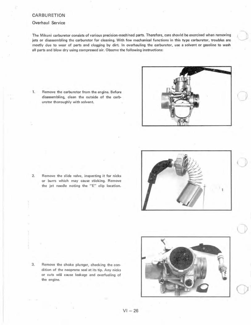
CARBURETION
Overhaul Service
The Mikuni carburetor consists of various precision-machined parts. Therefore, care should be exercised when removing jets or disassembling the carburetor for cleaning. With few mechanical functions in this type carburetor, troubles are mostly due to wear of parts and clogging by dirt. In overhauling the carburetor, use a solvent or gasoline to wash all parts and blow dry using compressed air. Observe the following instructions:
1. Remove the carburetor from the engine. Before disassembling, clean the outside of the carburetor thoroughly with solvent.
2. Remove the slide valve, inspecting it for nicks or burrs which may cause sticking. Remove the jet needle noting the "E" clip location.
3. Remove the choke plunger, checking the condition of the neoprene seal at its tip. Any nicks or cuts wiU cause leakage and overfueling of the engine.
") 1
VI-26
(

r~
..--( -
4. Remove the float bowl and main jet ban.io bolt (A).
5. Remove the inlet needle and seat assembly inspecting the needle (A) for any wear at its tip . NOTE: Do not bend the float arm during disassembly.
6. Remove the pilot jet (A) and needle jet (B) by removing the jet setter and pushing the needle jet into the slide valve chamber. Inspect the neoprene "0" ring (e) located on the needle jet setter for nicks or cuts. Wash all parts in solvent and blow all passages and jets with compressed air. Replace gaskets and parts which show wear or damage. Reassemble the carburetor, adjusting the float level before installing the float bowl. NOTE: Refer to page in this section for correct
float level adjustment-procedures.
CARBUR ETlaN
Overhaul Service
A
----,
VI- 27

CARBURETION
Fuel Pump
The fuel pumps for all Polaris engines are basically the same. The differences are in the size and location of the pumps. Pumps may be mounted on the crankcase or on the machine using an impulse hose.
In the two cycle engine, the pressure in the crankcase changes with the up and down stroke of the piston. The amplitudes of pressure vary according to the RPM and degree of throttle opening. Whether idling or full throttle, the pressure built up in the crankcase has enough amplitude to operate the pump.
When the piston is on the upstroke, crankcase pressure in that cylinder becomes less positive, the diaphragm in the fuel pump moves toward the engine causing a negative pressure or suction in the pump chamber which causes the inlet valve from the fuel supply to open and permits fuel to enter the chamber; this same suction causes the outlet valve (to the carburetor) to close so fuel cannot return from the carburetor.
When the piston begins its downward stroke, the pressure from the crankcase becomes positive, causing the fuel pump diaphragm to move in the opposite direction, reversing the pressure in the fuel pump chamber. This causes the inlet valve in the pump to close and the outlet valve (to the carburetor) to open, filling the float bowl in the carburetor. When the float level in the carburetor reaches its standard level the needle valve will close, preventing more fuel from entering the carburetor, even though the fuel pump continues to try to provide the carburetor with fuel.
VI-28
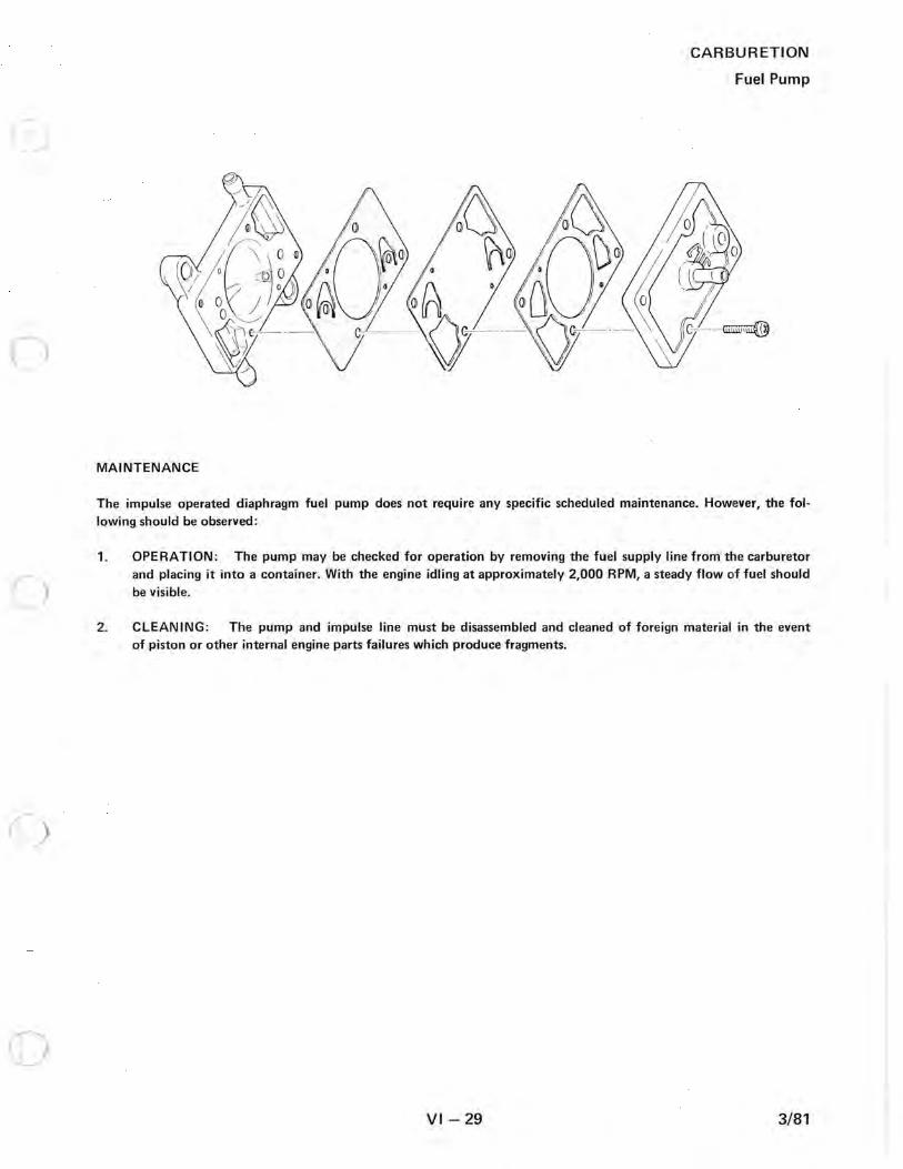
c)
MAINTENANCE
CARBURETION
Fuel Pump
The impulse operated diaphragm fuel pump does not require any specific scheduled maintenance. However, the following should be observed:
1. OPE RA TlON: The pump may be checked for operation by removing the fuel supply line from the carburetor and placing it into a container. With the engine idling at approximately 2,000 RPM, a steady flow of fuel should be visible.
2. CLEANING: The pump and impulse line must be disassembled and cleaned of foreign material in the event of piston or other internal engine parts failures which produce fragments.
VI-29 3/81

()
o