technical report #2 - pennsylvania state university 2.pdf · snow exposure factor (ce) 0.9 asce7-05...
TRANSCRIPT
Technical Report #2
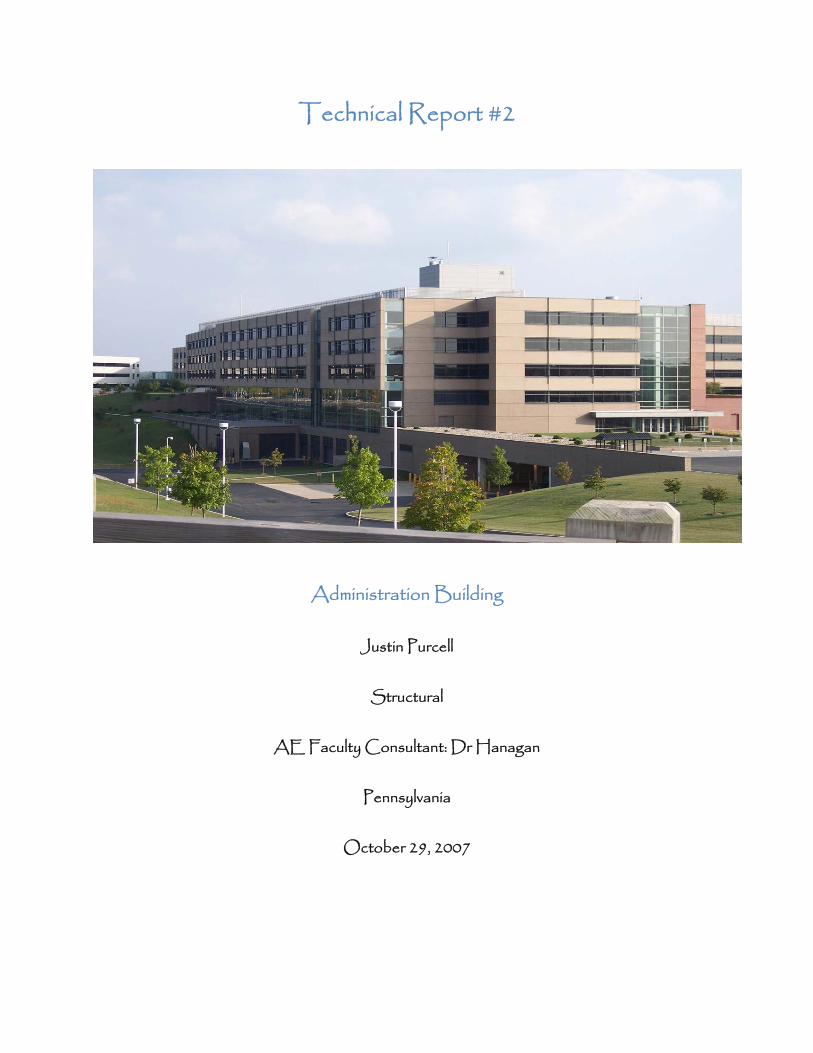
Administration Building
Justin Purcell
Structural
AE Faculty Consultant: Dr Hanagan
Pennsylvania
October 29, 2007
Purcell-Technical Report #2
Page 2 of 40
TABLE OF CONTENTS Executive Summary ............................................................................................................. 3 Structural System Overview ............................................................................................ 4 Loads ......................................................................................................................................... 8 System Analysis Overview ............................................................................................... 9 Floor System Comparisons .......................................................................................... 11 Comparison Spreadsheet .............................................................................................. 15 System Evaluation ............................................................................................................ 16
Appendix A: Hand Calculations Deflections ........................................................................................................................... 20 Weight .................................................................................................................................... 21 Wood Joists ........................................................................................................................ 22 1 Way Slab .......................................................................................................................... 23
Appendix B: Ram Outputs Composite Framing Plan ................................................................................................. 24 Non-Composite Framing Plan ...................................................................................... 25 Open Web Joists Framing Plan ................................................................................... 26 Composite and Non-Composite Deflections ........................................................ 27 Open Web Joist Deflections ....................................................................................... 29
Appendix C: Resources 1 Way Slab Design .......................................................................................................... 30 R. S. Means ......................................................................................................................... 33 Metal Deck .......................................................................................................................... 38 Open Web Joist Deck ................................................................................................... 39 Open Web Joist Fire Protection ................................................................................ 40
Purcell-Technical Report #2
Page 3 of 40
EXECUTIVE SUMMARY
The Administration Building is an office building in Pennsylvania which is 87’ tall, but only 67’ are above grade. It has five floors with the first floor being 20’ floor to floor height and the rest being 13.33’ floor to floor height. It is a rather long building with 560’ in the long direction and 203’ in the short direction.
The purpose of this report is to evaluate four different floor framing options and compare them to the existing composite metal deck system. Non-composite, Open web steel joists, 1 way slab and wood joists supported by steel girders were the four systems chosen to compare. To compare, we analyzed cost, fire protection, lead time, constructability, weight, vibration, depth, durability, column grid, lateral system, and deflections.
The non-composite system cost $6.8 Million with a lead time of less than 6 months. It is the 2nd heaviest system analyzed with a 30” depth and received a deflection of 1.9”. It would require no column grid change as everything would be the same, minus the composite action. In the end, it was dismissed as a possible solution simply because you can do the same thing but better with a composite system. The only other steel system analyzed is open web steel joists. It came in at $6.65 Million which is the cheapest solution and it has the least depth required of 24”. Spray-on fireproofing is going to be tough since there is nothing to catch the fireproofing. To fix this, you will have to put a steel mesh between the flanges for the fire proofing to adhere to. In the long run, this system was regarded as a possible solution due to its cost, depth and deflection. Another joist system was analyzed but this time it is wood I-joists supported by steel girders. This system is not very common in a commercial building like the Administration Building. This system came in at $6.8 Million but it requires a special detail to adhere to the 2-hour fire rating. This detail is described in detail in the fire protection section. A positive to this system is there is barley any lead time, it is extremely light and has a joist deflection of 0.3”. On the negative side, it will not be the easiest to construct because the contractor will not be familiar with this type of construction. Also a negative, is it has a depth of 45”, which has a huge architectural impact on the building. In the end, this system was not chosen as a possible solution. Finally the last system is a 1-way slab. The 1-way slab came in at $7.9 Million which requires extensive formwork and is labor intensive. This is the only system that has a lateral system change and this would change from a braced frame to a shear wall. This was the heaviest system analyzed which will make the footings significantly larger. Overall, this system was picked as a possible solution.

Purcell-Technical Report #2
Page 4 of 40
STRUCTURAL SYSTEM OVERVIEW: BUIDING INFORMATION:
This is an administration building for a confidential client in Pennsylvania that was constructed in July 2003. It offers offices and specialty amenity spaces as the architectural layout of 311,905 S.F. of usable floor area. There are five floors, four of which are above grade with a cost ranging between $70-75 million. FOUNDATION:
The foundation system will consist of reinforced concrete spread footings that are sized utilizing bearing capacities ranging from 4,000 psf at soil bearing footings and 15,000 psf at rock-bearing footings. Total building settlements will be less than 1” with differential settlements not exceeding ½” or 1/300, based on a 20’ bay. Typical perimeter frost walls are supported on continuous reinforced concrete strip footings. Foundation walls at basement or below grade levels are reinforced concrete basement walls designed for soil lateral loads and appropriate surcharge loads and supported by continuous reinforced concrete strip footings. These walls are drained on the soil side to minimize lateral surcharge loads on the walls and buildings. The slab on grade varies between a 5”, 6” and 8” thickness, typically with 6x6-W4.0xW4.0 W.W.F.
FLOOR SYSTEM:
The structural floor system is 3¼” concrete slab on a 3”, 20 gauge composite metal deck, totaling 6¼”. The metal deck utilizes ¾” steel studs, supported by wide-flange beams and wide-flange columns. The typical sizes of the beams range from W18x40 to W30x116. The girders range from W21x50 to W27x146. The columns range from W10x43 to W14x211. The concrete is lightweight weight (115 pcf), cast-in-place concrete and will have a 28 day strength of 4,000 psi. The concrete slab is reinforced with 6x6-W2.9xW2.9 W.W.F. to minimize plastic shrinkage cracking. The thickness of the concrete is established based on the required 2 hour fire rating for the floor construction without spray fireproofing applied to the underside of the metal deck. Structural steel shall comply with ASTM A572, Grade 50. Steel stud shear connectors shall conform to ASTM A108.
To maintain the 5’-0” building module within the typical bay sizes of 20’-0” and 40’-0”, the typical beams supporting the composite slab are spaced at 10’-0” on center. These beams supporting the composite slab for the typical bays span to girders oriented across the width of the building. The wide flange steel girders in the long direction or the building support the wide flange steel beams that span the 3 bay width of the building consisting of (1) 20’-0” and (2) 40’-0” bays. Spanning the beams across the width of the building works best in combination with a braced frame lateral load resisting system.
ROOF SYSTEM:
The structural roof system consists of a 1½”, 20 gauge, Type B, galvanized metal roof deck with spray fireproofing. Below mechanical equipment a concrete slab on composite metal deck is used instead of the standard roof deck and the concrete slab is reinforced with 6x6-W2.9xW2.9 W.W.F. to minimize shrinkage cracking. The framing members supporting the metal deck are either open-web joists or wide flange steel beams
Purcell-Technical Report #2
Page 5 of 40
at 4’-0” and 5’-0” centers. The beams supporting the composite slab are wide flange steel beams at 10’-0” centers that span the width of the building.
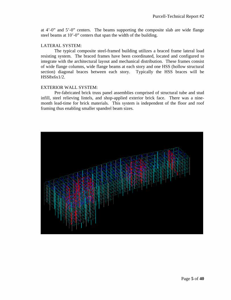
LATERAL SYSTEM:
The typical composite steel-framed building utilizes a braced frame lateral load resisting system. The braced frames have been coordinated, located and configured to integrate with the architectural layout and mechanical distribution. These frames consist of wide flange columns, wide flange beams at each story and one HSS (hollow structural section) diagonal braces between each story. Typically the HSS braces will be HSS8x6x1/2.
EXTERIOR WALL SYSTEM:
Pre-fabricated brick truss panel assemblies comprised of structural tube and stud infill, steel relieving lintels, and shop-applied exterior brick face. There was a nine-month lead-time for brick materials. This system is independent of the floor and roof framing thus enabling smaller spandrel beam sizes.
Purcell-Technical Report #2
Page 6 of 40
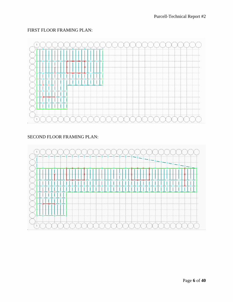
FIRST FLOOR FRAMING PLAN:
SECOND FLOOR FRAMING PLAN:
Purcell-Technical Report #2
Page 7 of 40
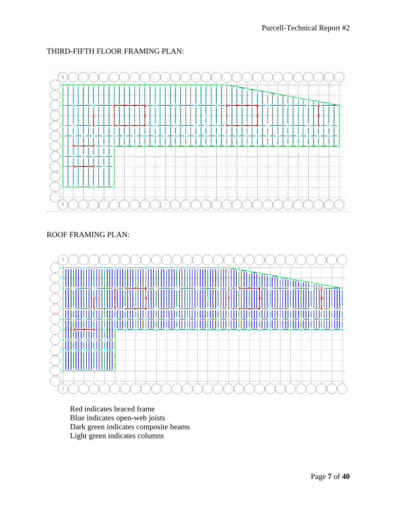
THIRD-FIFTH FLOOR FRAMING PLAN:
ROOF FRAMING PLAN:
Red indicates braced frame Blue indicates open-web joists Dark green indicates composite beams Light green indicates columns
Purcell-Technical Report #2
Page 8 of 40
LOADS
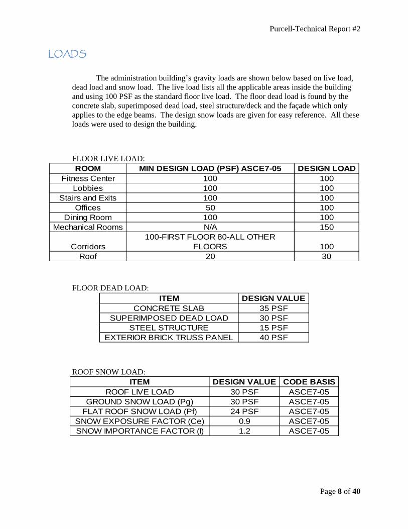
The administration building’s gravity loads are shown below based on live load, dead load and snow load. The live load lists all the applicable areas inside the building and using 100 PSF as the standard floor live load. The floor dead load is found by the concrete slab, superimposed dead load, steel structure/deck and the façade which only applies to the edge beams. The design snow loads are given for easy reference. All these loads were used to design the building.
FLOOR LIVE LOAD:
FLOOR DEAD LOAD:
ROOF SNOW LOAD:
ROOM MIN DESIGN LOAD (PSF) ASCE7-05 DESIGN LOADFitness Center 100 100
Lobbies 100 100Stairs and Exits 100 100
Offices 50 100Dining Room 100 100
Mechanical Rooms N/A 150
Corridors100-FIRST FLOOR 80-ALL OTHER
FLOORS 100Roof 20 30
ITEM DESIGN VALUECONCRETE SLAB 35 PSF
SUPERIMPOSED DEAD LOAD 30 PSFSTEEL STRUCTURE 15 PSF
EXTERIOR BRICK TRUSS PANEL 40 PSF
ITEM DESIGN VALUE CODE BASISROOF LIVE LOAD 30 PSF ASCE7-05
GROUND SNOW LOAD (Pg) 30 PSF ASCE7-05FLAT ROOF SNOW LOAD (Pf) 24 PSF ASCE7-05
SNOW EXPOSURE FACTOR (Ce) 0.9 ASCE7-05SNOW IMPORTANCE FACTOR (I) 1.2 ASCE7-05
Purcell-Technical Report #2
Page 9 of 40
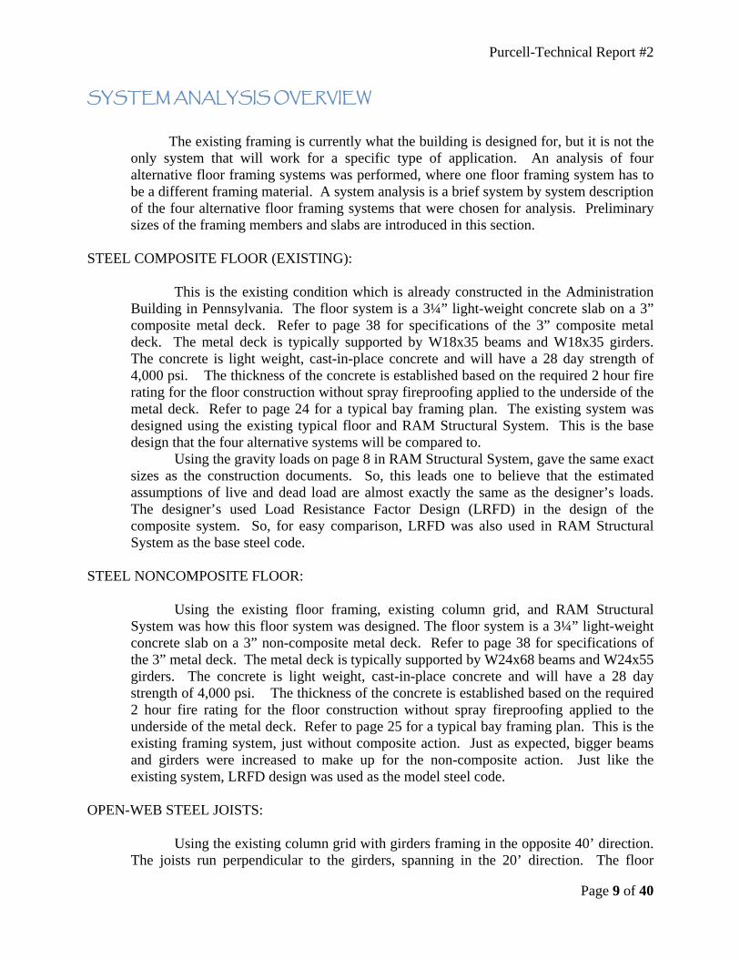
SYSTEM ANALYSIS OVERVIEW
The existing framing is currently what the building is designed for, but it is not the only system that will work for a specific type of application. An analysis of four alternative floor framing systems was performed, where one floor framing system has to be a different framing material. A system analysis is a brief system by system description of the four alternative floor framing systems that were chosen for analysis. Preliminary sizes of the framing members and slabs are introduced in this section.
STEEL COMPOSITE FLOOR (EXISTING):
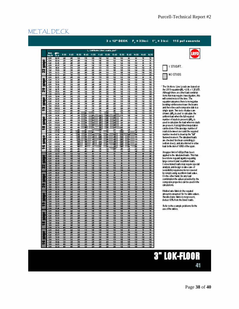
This is the existing condition which is already constructed in the Administration Building in Pennsylvania. The floor system is a 3¼” light-weight concrete slab on a 3” composite metal deck. Refer to page 38 for specifications of the 3” composite metal deck. The metal deck is typically supported by W18x35 beams and W18x35 girders. The concrete is light weight, cast-in-place concrete and will have a 28 day strength of 4,000 psi. The thickness of the concrete is established based on the required 2 hour fire rating for the floor construction without spray fireproofing applied to the underside of the metal deck. Refer to page 24 for a typical bay framing plan. The existing system was designed using the existing typical floor and RAM Structural System. This is the base design that the four alternative systems will be compared to. Using the gravity loads on page 8 in RAM Structural System, gave the same exact sizes as the construction documents. So, this leads one to believe that the estimated assumptions of live and dead load are almost exactly the same as the designer’s loads. The designer’s used Load Resistance Factor Design (LRFD) in the design of the composite system. So, for easy comparison, LRFD was also used in RAM Structural System as the base steel code.
STEEL NONCOMPOSITE FLOOR:
Using the existing floor framing, existing column grid, and RAM Structural System was how this floor system was designed. The floor system is a 3¼” light-weight concrete slab on a 3” non-composite metal deck. Refer to page 38 for specifications of the 3” metal deck. The metal deck is typically supported by W24x68 beams and W24x55 girders. The concrete is light weight, cast-in-place concrete and will have a 28 day strength of 4,000 psi. The thickness of the concrete is established based on the required 2 hour fire rating for the floor construction without spray fireproofing applied to the underside of the metal deck. Refer to page 25 for a typical bay framing plan. This is the existing framing system, just without composite action. Just as expected, bigger beams and girders were increased to make up for the non-composite action. Just like the existing system, LRFD design was used as the model steel code.
OPEN-WEB STEEL JOISTS:
Using the existing column grid with girders framing in the opposite 40’ direction. The joists run perpendicular to the girders, spanning in the 20’ direction. The floor
Purcell-Technical Report #2
Page 10 of 40
system is a 4” light-weight concrete slab on a 2” form deck. Refer to page 39 for specifications of the 2” form deck. The metal deck is typically supported by 18LH06 open-web steel joists spaced 4’ on center and W24x76 girders. The concrete is light weight, cast-in-place concrete and will have a 28 day strength of 4,000 psi. The thickness of the concrete is established based on the required 2 hour fire rating for the floor construction with cementitious sprayed fireproofing. The fireproofing is applied to the underside of the metal deck and applied to the web of the steel joists. A wire-mesh must be applied to the web of the joists for the cementitious sprayed fireproofing to adhere to. Refer to page 26 for a typical bay framing plan. This system was designed using the existing RAM Structural System, LRFD as the model steel code, and the SJI Standard Specification.
WOOD FLOOR JOISTS:
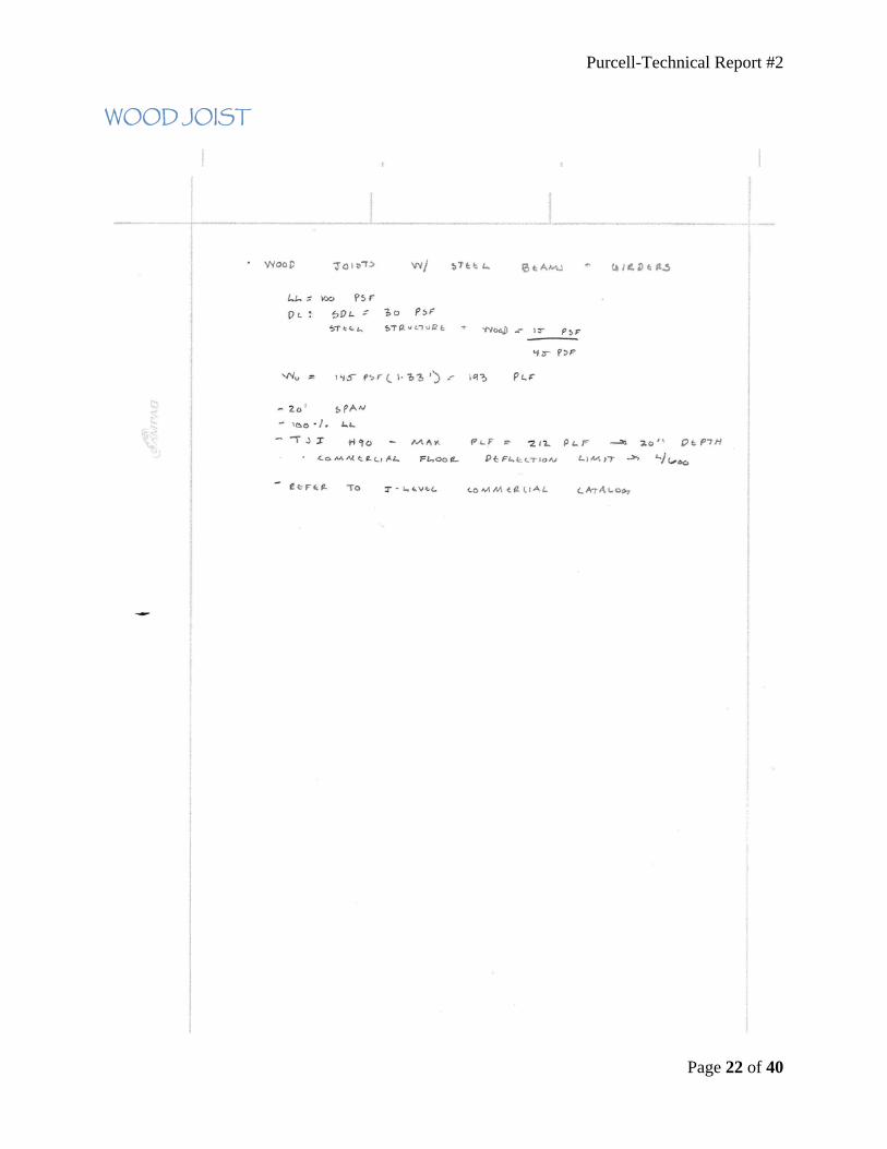
Using the existing column grid with steel girders framing in the opposite 40’ direction. The joists run perpendicular to the girders, spanning in the 20’ direction. The floor system is a 48/24 tongue and groove span rated sheathing (exposure 1). The wood deck is typically supported by TJI H90 open-web steel joists spaced at 16” on center and wide-flanged girders. This is a commercial grade I-joist with a depth of 20” and a commercial floor deflection limit of L/600. The sheathing is established based on the required 2 hour fire rating for the floor construction. Refer to page 12 for a more detailed description of the fire protection. This system was designed using existing beams and the I-Level design catalogs.
ONE WAY SLAB:
The existing column grid was used in conjunction with the beams framing in the 40’ direction, supported by the girders framing in the 20’ direction. Using the CRSI handbook load combination of 1.4D + 1.7L, a 10” slab was found using 3,000 PSI concrete strength. The beams were 16” x 28” and a 20” x 26” girder was found to carry the load using 4,000 PSI concrete strength. The CRSI handbook calculated the slab being 10” thick based on the live and dead loads. Using a 10” slab is more than sufficient to acquire the 2-hour fire rating.

Purcell-Technical Report #2
Page 11 of 40
FLOOR SYSTEM COMPARISONS
To compare the four alternative floor framing systems, eleven factors were chosen for the analysis between each system. The eleven items include cost, fire protection, lead time, constructability, weight, vibrations, depth of system, durability issues, column grid changes, lateral system changes, and deflection. Some criteria are more important than others, but all factors play a role in the decision of which systems are viable and which are not an option.
COST:
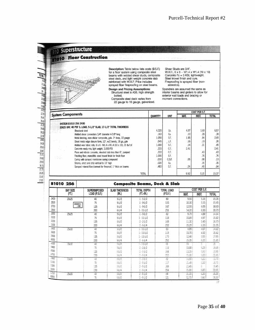
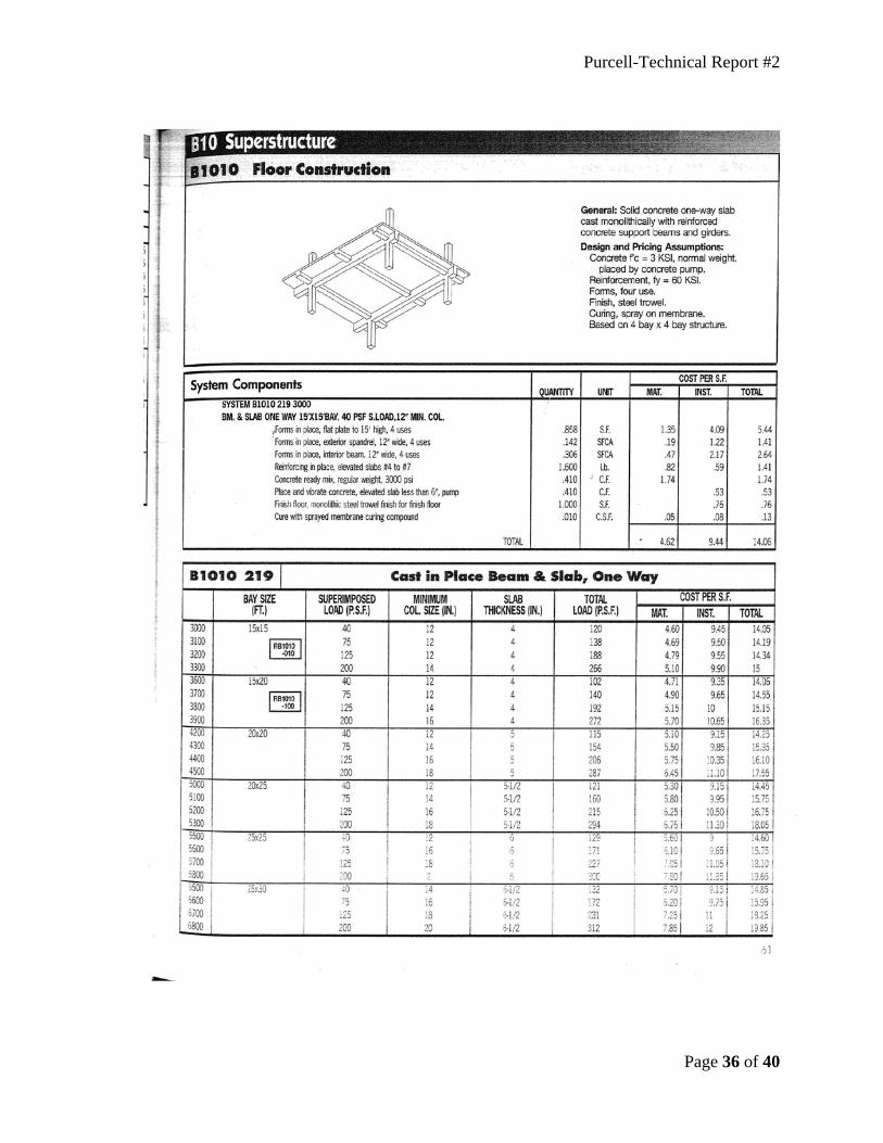
Using the R.S. Means Assemblies Cost Data Book, the cost per square foot was obtained for each framing system. The following represents an estimated cost for the framing systems on a 450,000 square foot building. Refer to page 33 for the R.S. Means Assemblies Cost Data that was used.
SYSTEM MATERIAL/
S.F. INSTALLATION/
S.F. TOTAL/
S.F. TOTAL
COMPOSITE 14.2 6.5 20.70 $9.31 Million
1 WAY SLAB 6.45 11.1 17.55 $7.90 Million
NONCOMPOSITE 11.55 3.65 15.2 $6.8 Million
WOOD JOISTS 10.55 4.38 15.14 $6.8 Million
OPEN WEB JOISTS
9.9 4.88 14.78 $6.65 Million
The cost per system is listed by the most expensive at the top to the least expensive at the bottom. For the wood joists, the cost of the steel beams was added, as they were not included. The non-composite, wood and steel joists were really close in the cost comparison of each other. The composite action is almost $2 Million more than the 1 way slab, which is surprising.
FIREPROTECTION:
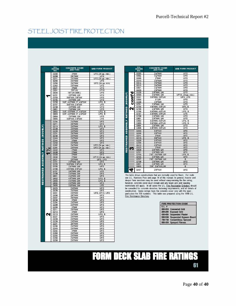
The metal deck and thickness of the concrete is established based on the required 2-hour fire rating for the floor construction without spray fireproofing applied to the underside of the metal deck. The 2 hour fire rating is satisfied with the concrete depth and metal deck for composite and non-composite systems. The steel beams, girders and open web joists must be sprayed with spray-on-fireproofing. The open web joists utilize a 2” USD form deck and the required slab thickness is 3-7/8” for lightweight concrete.
Purcell-Technical Report #2
Page 12 of 40
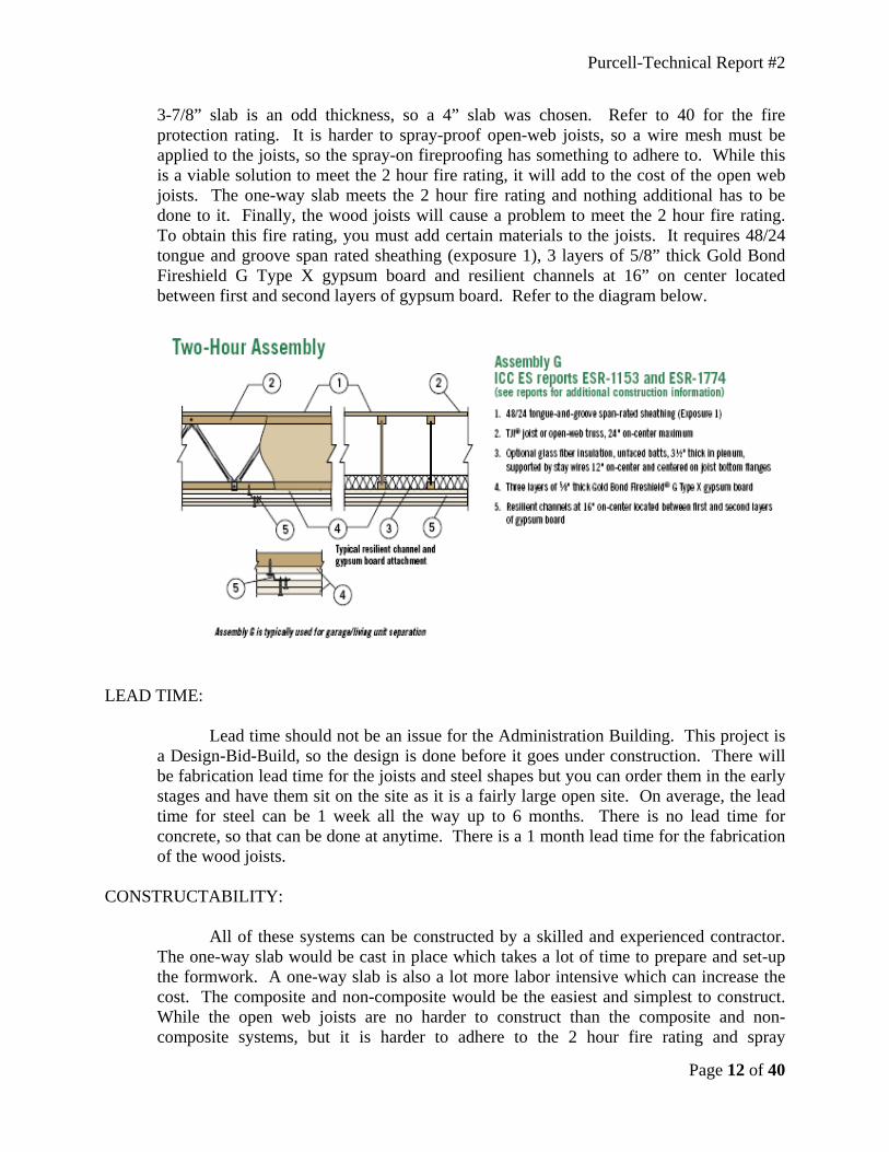
3-7/8” slab is an odd thickness, so a 4” slab was chosen. Refer to 40 for the fire protection rating. It is harder to spray-proof open-web joists, so a wire mesh must be applied to the joists, so the spray-on fireproofing has something to adhere to. While this is a viable solution to meet the 2 hour fire rating, it will add to the cost of the open web joists. The one-way slab meets the 2 hour fire rating and nothing additional has to be done to it. Finally, the wood joists will cause a problem to meet the 2 hour fire rating. To obtain this fire rating, you must add certain materials to the joists. It requires 48/24 tongue and groove span rated sheathing (exposure 1), 3 layers of 5/8” thick Gold Bond Fireshield G Type X gypsum board and resilient channels at 16” on center located between first and second layers of gypsum board. Refer to the diagram below.
LEAD TIME:
Lead time should not be an issue for the Administration Building. This project is a Design-Bid-Build, so the design is done before it goes under construction. There will be fabrication lead time for the joists and steel shapes but you can order them in the early stages and have them sit on the site as it is a fairly large open site. On average, the lead time for steel can be 1 week all the way up to 6 months. There is no lead time for concrete, so that can be done at anytime. There is a 1 month lead time for the fabrication of the wood joists.
CONSTRUCTABILITY:
All of these systems can be constructed by a skilled and experienced contractor. The one-way slab would be cast in place which takes a lot of time to prepare and set-up the formwork. A one-way slab is also a lot more labor intensive which can increase the cost. The composite and non-composite would be the easiest and simplest to construct. While the open web joists are no harder to construct than the composite and non-composite systems, but it is harder to adhere to the 2 hour fire rating and spray

Purcell-Technical Report #2
Page 13 of 40
fireproofing on them. The wood joist system is an odd system, so it might take some time to get used to as it is not common at all. With that in mind, it might add some difficulty to constructing it.
WEIGHT:
The weight of the structure was assumed not to be a problem for the preliminary analysis. Weight will affect the seismic loads but wind governs for this building anyway. Weight will also affect the footings, but the only system that has any significance causing the footings to increase would be the one-way slab. The one-way slab is significantly higher than the other floor systems. Below is an estimated weight of the floor systems for a 60’ x 100’ floor area. Refer to page 21 for the calculation of the weights.
FLOOR SYSTEM WEIGHT (#) 1-WAY SLAB 1,272,000
NONCOMPOSITE 299,852 OPEN-WEB JOISTS 295,462
COMPOSITE 292,525 WOOD JOISTS 55,234
VIBRATION:
Vibrations have a lot to do with the depth, weight, and stiffness of the system. With that in mind, 1-way slab, Composite, Non-composite, and open web joists should have no problem with vibrations. The wood joists would have more of a problem because they are not very deep and the joists themselves do not weigh very much. Floor vibration was a concern but it was checked in the RAM models and assuming for the wood joists with a deflection criteria of L/600, that would be somewhat of a stiff member and would be ignored. An in-depth analysis must be preformed to accurately access vibrations in the floor systems.
DEPTH:
SYSTEM DEPTH WOOD JOISTS 45.2” (TJI H90 + 1.5” SHEATHING + W24x62) 1 WAY SLAB 38” (28” BEAM + 10” SLAB)
NONCOMPOSITE 30” (W24x62 + 6.5” SLAB) COMPOSITE 27” (W21x44-EXISTING + 6.5” SLAB)
OPEN WEB JOISTS 23.75” (18LHO6 + 6” SLAB)
From the depth analysis above, wood joists came in last due to TJI joists have to sit on top of the girder which radically increases the total depth. It gets progressively better with each system but open web joists take the gold with the least depth. Depth of the floor is very important deciding factor of a floor system. A majority of buildings are
Purcell-Technical Report #2
Page 14 of 40
height controlled in certain areas of the world, especially areas like Washington D.C., so it is very important to minimize the floor depth to maximize the usable floor to floor height. The administration building is not height controlled, so floor depth is not an issue, but should not be taken lightly.
DURABILITY:
The concrete may crack, flake or spall because of freeze and thawing. It can also crack, flake or spall because of too much water in the mix and it was finished before the excess bleed water had a chance to evaporate. The wood may endure creep over time. Durability should not be an issue and the framing systems should be fine.
COLUMN GRID CHANGES:
The framing systems chosen for analysis all work with the existing column grid.
This makes it easy to compare different framing solutions without too much trouble. With the ability to work with the existing column grid, no changes were needed or executed to the existing grid.
LATERAL SYSTEM:
There are no changes that are required to the HSS braced frame for the Composite, non-composite, Open Web Steel Joists and the Wood Joist systems. For the 1 way slab, the lateral system will have to change to a shear wall.
DEFLECTIONS:
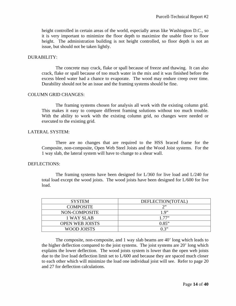
The framing systems have been designed for L/360 for live load and L/240 for total load except the wood joists. The wood joists have been designed for L/600 for live load.
SYSTEM DEFLECTION(TOTAL) COMPOSITE 2”
NON-COMPOSITE 1.9” 1 WAY SLAB 1.77”
OPEN WEB JOISTS 0.85” WOOD JOISTS 0.3”
The composite, non-composite, and 1 way slab beams are 40’ long which leads to
the higher deflection compared to the joist systems. The joist systems are 20’ long which explains the lower deflection. The wood joists system is lower than the open web joists due to the live load deflection limit set to L/600 and because they are spaced much closer to each other which will minimize the load one individual joist will see. Refer to page 20 and 27 for deflection calculations.

Purcell-Technical Report #2
Page 15 of 40
COMPARISON SPREADSHEET
After all eleven factors were considered and analyzed; a spreadsheet was created to clearly list the factors for each system. An actual value is inputted into the spreadsheet for easy comparison between the systems. The last two rows include further investigation and possible solution of the five floor framing systems. Further investigation would be necessary for an in-depth analysis of the system if more information is needed to accurately describe the system. The very last column indicates whether the system is a feasible based on the eleven factors.
ITEM COMPOSITE NONCOMPOSITE 1 WAY SLAB
OPEN WEB
JOISTS
WOOD JOISTS
COST $9.31 Million $6.8 Million $7.9 Million
$6.65 Million
$6.8 Million
FIRE PROTECTION None None None Spray-On
Special Detail
LEAD TIME <6 Months <6 Months None <6 Months
<1 Month
CONSTRUCTIBILITY Easy Easy Extensive Formwork Easy Moderate
WEIGHT 292,525# 299,852# 1,272,000# 295,462# 55,234# VIBRATION PROBLEM No No No Maybe Maybe
DEPTH 27” 30” 38” 23.75” 45.2”
DURABILITY ISSUES None None Crack,
Flake, or Spall
None Creep
COLUMN GRID CHANGES No No No No No
LATERAL SYSTEM CHANGES None None Shear Wall None None
DEFLECTIONS 2” 1.9” 1.77” 0.85” 0.3” FURTHER
INVESTIGATION No No No No Yes
POSSIBLE SOLUTION Yes No Yes Yes No

Purcell-Technical Report #2
Page 16 of 40
SYSTEM EVALUATION
The purpose of this report is to evaluate four different floor framing options and compare them to the existing composite metal deck system. Non-composite, Open web steel joists, 1 way slab and wood joists supported by steel girders were the four systems chosen to compare. To compare, we analyzed cost, fire protection, lead time, constructability, weight, vibration, depth, durability, column grid, lateral system, and deflections.
COMPOSITE: Advantages: • No additional fire protection needed • Can be easily constructed • Weight of structure being 292,525 pounds • No vibration problem • Small depth of structural floor which is 27” • No durability problems • No changes in the column grid • No lateral system changes Disadvantages: • Most expensive system at $9.31 million • Lead time up to 6 months • Highest deflection at 2” NON-COMPOSITE: Advantages: • Fairly cheap at $6.8 million • No additional fire protection needed • Can be easily constructed • No vibration problem • Average depth of structural floor being 30” • No durability issues • No changes in the column grid • No changes to the lateral system Disadvantages: • Long lead time of up to 6 months • Fairly heavy system coming in at almost 300,000 pounds • High deflection of 1.9” 1 WAY SLAB: Advantages: • No additional fire protection needed • No vibration problem • No column grid changes • Change lateral system to shear walls

Purcell-Technical Report #2
Page 17 of 40
Disadvantages: • $7.9 million price tag • Extensive formwork • System weighing the most at 1,272,000 pounds • No vibration problem • Large depth of structural floor at 38” • Concrete can crack, flake or spall if installed wrong • Deflection of 1.77” OPEN WEB JOISTS: Advantages: • Cheapest system of $6.65 million • Easy constructability • Light structure weighing in at 295,462 pounds • Smallest structural floor of 23.75” • No fatigue problems • No lateral system changes • Deflection of 0.85” Disadvantages: • Spray-on fireproofing and wire mess added to the web • Lead time up to 6 months WOOD JOISTS: Advantages: • Cost of $6.8 million • Short lead time of less than 1 month • Lightest system of 55,234 pounds • No column grid changes • No lateral system changes • Deflection of 0.3” Disadvantages: • Special fire protection design needed • Moderately hard to construct • Vibration problems may exist • Highest depth of structural floor of 45.2” • Creep will be an issue over time

Purcell-Technical Report #2
Page 18 of 40
The existing framing which consists of a composite metal deck is currently what is designed for the building. It is the most sensible choice for the floor framing and is why the design professional chose the composite system. It is the most expensive system at $9.31 million with a long lead time for the steel; however it has many benefits that make it the best choice. No additional fire protection is needed; it can be constructed fairly easily because it is a standard system, which both will help keep the cost down. It is one of the lighter systems, weighing in at 292,525 pounds and it maximizes the floor to ceiling height by keeping the depth of the floor minimal.
The non-composite system is almost the same thing as the composite system; it just does not have the composite action. Without the composite action, it will significantly keep the cost down because placing the studs is very expensive in the composite system. It might keep the cost down, but without composite action, the beams and girders will increase a couple sizes to make up for the strength composite action gives. With bigger beams and girders, the structure will increase in weight and it comes in as the second heaviest system at almost 300,000 pounds. With these factors in mind, non-composite was not chosen as a possible solution simply because you can do the same thing but better with a composite system.
The next system analyzed was the 1-way concrete slab system. It is cheaper than the composite system by a little over $1 million, but with changing over to an entirely concrete structure will significantly increase the weight of the building. This system is not even close to the other system in terms of weight, weighing in at 1,272,000 pounds. With all that extra weight, the foundation will have to drastically increase in size and will in turn drive the cost of the building up. With a 10” concrete slab, fire protection is not an issue. Being this system being cheaper and no lead time for concrete is why this was chosen as a possible solution.
Open web joists was another system analyzed for comparison against the composite system. This system has a lot of advantages with only a few disadvantages. It is the cheapest framing system analyzed at $6.65 million, which is almost $3 million cheaper than composite. It is almost the same weight of the composite system, so foundation change will not be an issue. It has the smallest structural floor depth of 23.75”, which maximizes the floor to ceiling height. However, fire protection is an issue where additional measure must be taken. Wire mess must be added to the web for the required spray-on fire proofing to be applied to maintain the 2-hour fire rating. Just like the composite system, this system has a lead time of up to 6 months. With all these factors considered, open web joists were chosen as a possible solution.
The last and final system chosen for analysis is the wood joists system on steel girders. It is a fairly cheap system of $6.8 million and a short lead time for the wood joists. It is incredibly lighter than the composite system, but it has many downfalls. Too many extras have to be added to this system to maintain the 2-hour fire rating. It will be moderately hard to construct because it is not common at all and vibration problems can arise with this light of a system. Wood joists have the biggest depth of all systems of 45.2”. This system has too many significant disadvantages, so this was not chosen as a possible solution.
Overall, two systems were chosen and two systems were not chosen. 1-way slab and open web joists were honorable systems in comparison to the composite system, so
Purcell-Technical Report #2
Page 19 of 40
they were chosen. Non-composite and wood joists were not very good systems in comparison to the composite system, so they were disregarded as possible solutions.

Purcell-Technical Report #2
Page 20 of 40
DEFLECTIONS

Purcell-Technical Report #2
Page 21 of 40
WEIGHT
Purcell-Technical Report #2
Page 22 of 40
WOOD JOIST

Purcell-Technical Report #2
Page 23 of 40
1 WAY SLAB

Purcell-Technical Report #2
Page 24 of 40
COMPOSITE FRAMING PLAN

Purcell-Technical Report #2
Page 25 of 40
NON-COMPOSITE FRAMING PLAN

Purcell-Technical Report #2
Page 26 of 40
OPEN WEB JOISTS FRAMING PLAN

Purcell-Technical Report #2
Page 27 of 40
COMPOSITE AND NON-COMPOSITE DEFLECTIONS

Purcell-Technical Report #2
Page 28 of 40

Purcell-Technical Report #2
Page 29 of 40
OPEN WEB JOISTS DEFLECTIONS

Purcell-Technical Report #2
Page 30 of 40
1 WAY SLAB DESIGN

Purcell-Technical Report #2
Page 31 of 40

Purcell-Technical Report #2
Page 32 of 40

Purcell-Technical Report #2
Page 33 of 40
R.S. MEANS

Purcell-Technical Report #2
Page 34 of 40
Purcell-Technical Report #2
Page 35 of 40
Purcell-Technical Report #2
Page 36 of 40

Purcell-Technical Report #2
Page 37 of 40
Purcell-Technical Report #2
Page 38 of 40
METAL DECK

Purcell-Technical Report #2
Page 39 of 40
STEEL JOIST DECK
Purcell-Technical Report #2
Page 40 of 40
STEEL JOIST FIRE PROTECTION