technical product datasheet · 9/13/2016 · p/n 610-00046 rev 1.00 product high current pdm – 8...
TRANSCRIPT

ISO 9001 CERTIFIED
607 NW 27th Ave Ocala, FL 34475
Phone: (352) 629-5020 or 800-533-3569 Fax: (352)-629-2902
SUITABLE FOR OEM DISTRIBUTION ONLY
TECHNICAL PRODUCT DATASHEET
High Current PDM 8 Output / 4 Input 4 MFI Input
P/N 610-00046
FORM-ENG-0018 REV A 06-02-03

FORM-ENG-0018 REV A 05-27-03
607 NW 27th Ave Ocala, FL 34475
Ph: 352-629-5020 or 1-800-533-3569 Fax : 352-629-2902 or 1-800-520-3473
TECHNICAL DATA SHEET PAGE 1 OF 22
DATE 9/13/2016
PRODUCT GROUP ES-Key P/N 610-00046 REV 1.00
PRODUCT High Current PDM – 8 output / 4 INPUT / 4MFI input BY GMC
Manual P/N FSG-MNL-00164
1. REVISION LOG ................................................................................................................................................................................ 2 2. PART NUMBERS ............................................................................................................................................................................. 3
2.1. PDM PART NUMBERS .................................................................................................................................................................. 3 2.2. MISCELLANEOUS PART NUMBERS ................................................................................................................................................. 3
3. OVERVIEW ...................................................................................................................................................................................... 4 3.1. PRODUCT DESCRIPTION ............................................................................................................................................................... 4 3.2. FEATURES .................................................................................................................................................................................. 4 3.3. INDICATORS AND BUTTONS .......................................................................................................................................................... 4
3.3.1. Display ................................................................................................................................................................................. 5 3.3.2. LED diagnostic indicators ..................................................................................................................................................... 6 3.3.3. Buttons ................................................................................................................................................................................ 7
3.4. DEVICE TYPE AND ADDRESS ......................................................................................................................................................... 7 4. INPUT / OUTPUT DETAIL ................................................................................................................................................................ 8
4.1. SOLID STATE POSITIVE OUTPUTS .................................................................................................................................................. 8 4.1.1. Circuit protection (software circuit breaker) .......................................................................................................................... 8 4.1.2. Flash outputs ....................................................................................................................................................................... 8 4.1.3. Pulse Width Modulate (PWM) outputs ................................................................................................................................ 10
4.2. SELECTABLE POLARITY INPUTS .................................................................................................................................................. 10 4.2.1. Viewing the configured input polarity .................................................................................................................................. 10
5. ES-KEY NETWORK DETAIL.......................................................................................................................................................... 11 5.1. INPUT/OUTPUT MEMORY SPACE .................................................................................................................................................. 11
5.1.1. Standard I/O memory space .............................................................................................................................................. 11 5.2. ENTERING PASSWORDS ............................................................................................................................................................. 12
5.2.1. List of passwords ............................................................................................................................................................... 12 5.3. INPUT MODE ............................................................................................................................................................................. 13
5.3.1. Set Input Mode .................................................................................................................................................................. 13 5.3.2. View Input Mode ................................................................................................................................................................ 13
5.4. INPUT POLARITY ........................................................................................................................................................................ 14 5.4.1. Set polarity ......................................................................................................................................................................... 14 5.4.2. View polarity ...................................................................................................................................................................... 14
5.5. REFERENCE SELECTION ............................................................................................................................................................ 14 5.5.1. Set Reference Mode .......................................................................................................................................................... 14 5.5.2. Get Reference Mode .......................................................................................................................................................... 15
5.6. ADDRESS CONFIGURATION ........................................................................................................................................................ 16 5.7. DEVICE TYPE CONFIGURATION ................................................................................................................................................... 16
5.7.1. Set device type .................................................................................................................................................................. 16 5.7.2. View device type ................................................................................................................................................................ 16
5.8. LOAD DEFAULTS ........................................................................................................................................................................ 17 6. MOUNTING AND INSTALLATION ................................................................................................................................................. 18
6.1. OVERALL DIMENSIONS ............................................................................................................................................................... 18 6.2. MOUNTING DIMENSIONS............................................................................................................................................................. 18
7. CONNECTOR DESCRIPTIONS ..................................................................................................................................................... 19 7.1. GRAY CONNECTOR .................................................................................................................................................................... 19 7.2. BLACK CONNECTOR (MIDDLE) .................................................................................................................................................... 19 7.3. BLACK CONNECTOR .................................................................................................................................................................. 19 7.4. HIGH POWER CONNECTOR ......................................................................................................................................................... 20
8. TECHNICAL DETAILS AND COMPLIANCES ................................................................................................................................ 21 9. REFERENCES ............................................................................................................................................................................... 22
9.1. LIST OF FIGURES ....................................................................................................................................................................... 22 9.2. LIST OF TABLES ......................................................................................................................................................................... 22

FORM-ENG-0018 REV A 05-27-03
607 NW 27th Ave Ocala, FL 34475
Ph: 352-629-5020 or 1-800-533-3569 Fax : 352-629-2902 or 1-800-520-3473
TECHNICAL DATA SHEET PAGE 2 OF 22
DATE 9/13/2016
PRODUCT GROUP ES-Key P/N 610-00046 REV 1.00
PRODUCT High Current PDM – 8 output / 4 INPUT / 4MFI input BY GMC
Manual P/N FSG-MNL-00164
1. Revision Log
Rev Date Changes 1.00 9/13/2016 Initial revision
Product specifications in this manual are subject to change without notice.

FORM-ENG-0018 REV A 05-27-03
607 NW 27th Ave Ocala, FL 34475
Ph: 352-629-5020 or 1-800-533-3569 Fax : 352-629-2902 or 1-800-520-3473
TECHNICAL DATA SHEET PAGE 3 OF 22
DATE 9/13/2016
PRODUCT GROUP ES-Key P/N 610-00046 REV 1.00
PRODUCT High Current PDM – 8 output / 4 INPUT / 4MFI input BY GMC
Manual P/N FSG-MNL-00164
2. Part Numbers 2.1. PDM part numbers
ES-Key High Current PDM 610-00046
Documentation (available from Class 1’s website - www.class1.com)
Full Manual (this manual) FSG-MNL-00164 Quick Manual FSG-MNL-00165
2.2. Miscellaneous part numbers
PDM connector items
Deutsch 12- position mating plug - GREY DT06-12SA Deutsch 12- position mating plug wedge lock W12S Deutsch DT series socket (16 GA) 0462-201-16141 Deutsch DT series socket (16 GA) - GOLD 0462-201-1631 Deutsch 4-position mating plug – GREY DTP06-4S Deutsch 4- position mating plug – BLACK DTP06-4S-E004 Deutsch 4- position mating plug wedge lock WP-4S Deutsch DTP series socket (12 GA) 0462-203-12141 Deutsch DTP series socket (12 GA) - GOLD 0462-210-12141 High current mating pigtail harness, 12 inches (2 AWG) 121700 Cannon 1-way circular high power plug 121583-0013 Cannon 2 AWG socket 031-8521-020 Cannon 4 AWG socket 031-8521-010 Cannon Hexagonal nut 217-8516-010 Cannon cable seal - 0.409in [10.4mm] to 0.472in [12.0mm] 351-8697-001
CAN connector items
Deutsch 3- position mating plug - GRAY DT06-3S Deutsch 3- position mating plug wedge lock - BLUE W3S-1939 Deutsch 3- position mating plug wedge lock - ORANGE W3S Deutsch DT series socket (16 GA) - GOLD 0462-201-1631 Deutsch DT series 3-way “Y” receptacle DT04-3P-P007 Deutsch 3- position mating plug with terminating resistor DT06-3S-P006

FORM-ENG-0018 REV A 05-27-03
607 NW 27th Ave Ocala, FL 34475
Ph: 352-629-5020 or 1-800-533-3569 Fax : 352-629-2902 or 1-800-520-3473
TECHNICAL DATA SHEET PAGE 4 OF 22
DATE 9/13/2016
PRODUCT GROUP ES-Key P/N 610-00046 REV 1.00
PRODUCT High Current PDM – 8 output / 4 INPUT / 4MFI input BY GMC
Manual P/N FSG-MNL-00164
3. Overview
3.1. Product description The High Current PDM (p/n 610-00046) is a Class 1 ES-KeyTM module with 8 high current positive outputs, 4 selectable polarity inputs designed for use within an ES-Key electrical system network, and 4 “MFI” (Multi-Function Inputs). This allows 4 inputs to be polarity selectable inputs and 4 inputs that have analog capability (0-5volt, 0-30volt, 4-20mA, Thermistor, and Frequency). Input 7 also has the ability to be reconfigured to a voltage reference output that is selectable between 5 volt and 9 volt.
3.2. Features
• 8 positive polarity solid state outputs (30 Amps each) section 4.1 • 8 selectable polarity (positive or ground) digital inputs section 4.2 • Digital Circuit Breakers on all positive polarity outputs section 4.1.1 • Output PWM control section 4.1.3 • Output FLASH control section 4.1.2
3.3. Indicators and buttons The High Current PDM has a 7-segment display, three LED indicators, and two buttons for diagnostic, indication, and configuration purposes.
Figure 1. High Density PDM indicators and buttons.

FORM-ENG-0018 REV A 05-27-03
607 NW 27th Ave Ocala, FL 34475
Ph: 352-629-5020 or 1-800-533-3569 Fax : 352-629-2902 or 1-800-520-3473
TECHNICAL DATA SHEET PAGE 5 OF 22
DATE 9/13/2016
PRODUCT GROUP ES-Key P/N 610-00046 REV 1.00
PRODUCT High Current PDM – 8 output / 4 INPUT / 4MFI input BY GMC
Manual P/N FSG-MNL-00164
3.3.1. Display
The High Current PDM has a 7-segment LED display to show operational information.
Figure 2. High Density PDM display.
During normal operation the display shows the High Current PDM’s ES-Key address (Table 1).
Display Address
0
1
2
3
4
5
Display Address
6
7
8
9
10
11
Display Address
12
13
14
15
Table 1. Normal operation address display.
The display is also used to show password and configuration information.
A flashing address display indicates a PRIMARY address conflict with another module of the same device type.

FORM-ENG-0018 REV A 05-27-03
607 NW 27th Ave Ocala, FL 34475
Ph: 352-629-5020 or 1-800-533-3569 Fax : 352-629-2902 or 1-800-520-3473
TECHNICAL DATA SHEET PAGE 6 OF 22
DATE 9/13/2016
PRODUCT GROUP ES-Key P/N 610-00046 REV 1.00
PRODUCT High Current PDM – 8 output / 4 INPUT / 4MFI input BY GMC
Manual P/N FSG-MNL-00164
3.3.2. LED diagnostic indicators
The High Current PDM has three LED diagnostic indicators: SYSTEM PWR, DRIVER PWR, and COM.
Figure 3. High Current PDM LED indicators.
SYSTEM PWR LED The red system power (SYSTEM PWR) LED indicates the state of the system power input (pin 1) and system ground input (pin 12) of the gray connector.
LED state Description
ON Power is applied to pin 1 and ground applied to pin 12 of the gray connector.
OFF Either power (pin 1) and/or ground (pin 12) is missing.
Table 2. SYSTEM PWR LED states.
DRIVER PWR LED The red driver power (DRIVER PWR) LED indicates the state of the driver power input (large single pin Cannon connector).
LED state Description
ON Power is applied to the driver power pin.
OFF Power is NOT applied to the driver power pin.
Table 3. DRIVER PWR LED states.
COM LED The green communication (COM) LED indicates the state of the High Density PDM’s CAN communication.
LED state Description
ON CAN communication active.
OFF LED or module is inoperative
SLOW FLASH (1 Hz)
CAN bus okay, no communication with ECU. Verify CAN bus connection to ECU.
FAST FLASH (10 Hz)
CAN bus error (passive). Verify terminating resistors are correctly installed on CAN bus.
DOUBLE BLINK CAN bus error (active). Evaluate CAN bus wiring for shorts, improper wiring, etc.
Table 4. COM LED states.

FORM-ENG-0018 REV A 05-27-03
607 NW 27th Ave Ocala, FL 34475
Ph: 352-629-5020 or 1-800-533-3569 Fax : 352-629-2902 or 1-800-520-3473
TECHNICAL DATA SHEET PAGE 7 OF 22
DATE 9/13/2016
PRODUCT GROUP ES-Key P/N 610-00046 REV 1.00
PRODUCT High Current PDM – 8 output / 4 INPUT / 4MFI input BY GMC
Manual P/N FSG-MNL-00164
3.3.3. Buttons
The High Current PDM has two buttons (green SQUARE, red CIRCLE) which are used to enter passwords (see section 5.2). The display will show a “1” momentarily when the green SQUARE button is pressed and a “0” momentarily when the red CIRCLE button is pressed.
Figure 4. High Current PDM buttons.
Surface may be HOT when operating with high current. Use caution when operating buttons.
3.4. Device type and address
The High Current PDM is recognized by the ES-Key Professional software as a Power Distribution Module (default), but may be configured via password as an Input Output Module (see section 5.7.1). The High Density PDM’s address is 0 (default), but may be configured to any valid ES-Key address by entering a password (see section 5.6).

FORM-ENG-0018 REV A 05-27-03
607 NW 27th Ave Ocala, FL 34475
Ph: 352-629-5020 or 1-800-533-3569 Fax : 352-629-2902 or 1-800-520-3473
TECHNICAL DATA SHEET PAGE 8 OF 22
DATE 9/13/2016
PRODUCT GROUP ES-Key P/N 610-00046 REV 1.00
PRODUCT High Current PDM – 8 output / 4 INPUT / 4MFI input BY GMC
Manual P/N FSG-MNL-00164
4. Input / Output Detail
4.1. Solid state positive outputs Outputs 0 through 7 utilize solid state, fully protected high-side drivers that feature overload protection, current limitation, and transient protection. These output drivers replace the requirement of a relay and circuit breaker. High current rating
Each high current output is capable of supplying 30 Amps continuously. However, each Deutsch connector must be limited to a maximum of 100 Amps. The high current outputs are located on the black and green Deutsch connectors.
The OEM is responsible for limiting each Deutsch connector to a maximum of 100 Amps of output current and to ensure than no more than 200 Amps is permitted through the power supply cable.
Combining multiple outputs in an effort to increase load carrying capability is NOT recommended due to current balancing issues which may cause over-current conditions.
4.1.1. Circuit protection (software circuit breaker)
An output will automatically turn OFF when its current exceeds 31.0 Amps (tolerance +/- .5 amps) for 3 seconds. The module will attempt to turn ON and verify the load two more times at 5 second intervals. If the output is still overloaded it will remain OFF. An output’s "circuit breaker" feature can be reset by de-activating the output and then re-activating the output through the ES-Key network. When an output is in an over-current situation a fault is logged to the USM and data logger.
4.1.2. Flash outputs
The High Current PDM has the integrated capability to flash outputs for use with flashing lights, wig-wag lights, etc. (refer to the I/O memory space table in section 5.1.1). The outputs have the capability to flash at two flash rates: 150 pulses per minute (2.5 Hz) and 75 pulses per minute (1.25 Hz). Outputs 0 - 3 flash on the “A” pulse, and outputs 4 - 7 flash on the “B” pulse. This logic makes implementing alternating flashers quite simple. Output memory spaces 12 through 19 control the output flash feature and output memory spaces 20 control the flash rate (see section 5.1.1). Activate an output’s flash output (output memory space 0-7) to begin flashing the output. The physical output (output memory space 0-7) should be OFF.
Figure 5. Output banks A and B flash rates.

FORM-ENG-0018 REV A 05-27-03
607 NW 27th Ave Ocala, FL 34475
Ph: 352-629-5020 or 1-800-533-3569 Fax : 352-629-2902 or 1-800-520-3473
TECHNICAL DATA SHEET PAGE 9 OF 22
DATE 9/13/2016
PRODUCT GROUP ES-Key P/N 610-00046 REV 1.00
PRODUCT High Current PDM – 8 output / 4 INPUT / 4MFI input BY GMC
Manual P/N FSG-MNL-00164
An output’s flash occurs on the opposite bank when its flash output is ON and its physical output is ON. For example, output 0 normally flashes on the “A” pulse (its primary BANK), but when its flash output memory space 12) and its physical output memory space 0 are activated together output 0 flashes on the “B” pulse (its alternate BANK).
Output memory space
Flash memory space
Result
OFF OFF Physical output is OFF
ON OFF Physical output is ON
OFF ON Physical output is flashing on its primary BANK pulse
ON ON Physical output is flashing on its alternate BANK pulse
Table 5. Flash logic.

FORM-ENG-0018 REV A 05-27-03
607 NW 27th Ave Ocala, FL 34475
Ph: 352-629-5020 or 1-800-533-3569 Fax : 352-629-2902 or 1-800-520-3473
TECHNICAL DATA SHEET PAGE 10 OF 22
DATE 9/13/2016
PRODUCT GROUP ES-Key P/N 610-00046 REV 1.00
PRODUCT High Current PDM – 8 output / 4 INPUT / 4MFI input BY GMC
Manual P/N FSG-MNL-00164
4.1.3. Pulse Width Modulate (PWM) outputs
Outputs can be controlled ON at reduced power by activating the output’s associated PWM control in the output memory space (refer to the output memory space table in section 5.1.1). For example, activating output memory space 24 (PWM control of physical output 0) while NOT activating output memory space 0 (output control of physical output 0) will cause physical output 0 to be ON with PWM. This feature is useful for dimming lights, etc. The table below shows the interaction of a physical output’s control and PWM controls in the output memory space.
Output control memory space
PWM control memory space
Result
OFF OFF Physical output is OFF
ON OFF Physical output is ON
OFF ON Physical output is ON with PWM 60%
ON ON Physical output is ON (no PWM)
Table 6. PWM logic.
For example, as shown in the table above, if the output and PWM are activated the load for a physical output will be ON. To set the physical output to PWM (reduced power) mode it is necessary only to shed the primary output address for the desired output.
4.2. Selectable polarity inputs
The High Current PDM has 8 selectable polarity inputs (positive or ground). The state of the inputs is reported in the standard input memory space (see section 5.1.1). The default polarity of the inputs is positive, but they may be changed by entering a special password (see section 5.3).
4.2.1. Viewing the configured input polarity
The input’s configured polarity may be verified by entering a password and watching the display (see section 5.4.2).

FORM-ENG-0018 REV A 05-27-03
607 NW 27th Ave Ocala, FL 34475
Ph: 352-629-5020 or 1-800-533-3569 Fax : 352-629-2902 or 1-800-520-3473
TECHNICAL DATA SHEET PAGE 11 OF 22
DATE 9/13/2016
PRODUCT GROUP ES-Key P/N 610-00046 REV 1.00
PRODUCT High Current PDM – 8 output / 4 INPUT / 4MFI input BY GMC
Manual P/N FSG-MNL-00164
5. ES-Key Network Detail
5.1. Input/output memory space
The High Current PDM uses ES-Key defined input and output memory space. The High Current PDM uses the standard I/O memory space for the polarity selectable inputs, physical outputs, Flash, and PWM control.
5.1.1. Standard I/O memory space
I N P U T M E M O R Y S P A C E O U T P U T M E M O R Y S P A C E
INPUT DESCRIPTION OUTPUT LOCATION 0 Physical input 0 0 Physical output 0 30A, positive 1 Physical input 1 1 Physical output 1 30A, positive 2 Physical input 2 2 Physical output 2 30A, positive 3 Physical input 3 3 Physical output 3 30A, positive 4 Physical input 4 4 Physical output 4 30A, positive 5 Physical input 5 5 Physical output 5 30A, positive 6 Physical input 6 6 Physical output 6 30A, positive 7 Physical input 7 7 Physical output 7 30A, positive 8 reserved 8 reserved 9 reserved 9 reserved 10 reserved 10 reserved 11 reserved 11 reserved 12 reserved 12 Flash output 0 13 reserved 13 Flash output 1 14 reserved 14 Flash output 2 15 reserved 15 Flash output 3 16 reserved 16 Flash output 4 17 reserved 17 Flash output 5 18 reserved 18 Flash output 6 19 reserved 19 Flash output 7 20 reserved 20 Flash period (ON = 150Hz, OFF = 75Hz) 21 reserved 21 reserved 22 reserved 22 reserved 23 reserved 23 reserved 24 reserved 24 PWM output 0 25 reserved 25 PWM output 1 26 reserved 26 PWM output 2 27 reserved 27 PWM output 3 28 reserved 28 PWM output 4 29 reserved 29 PWM output 5 30 reserved 30 PWM output 6 31 reserved 31 PWM output 7
Table 7. Standard I/O memory space.

FORM-ENG-0018 REV A 05-27-03
607 NW 27th Ave Ocala, FL 34475
Ph: 352-629-5020 or 1-800-533-3569 Fax : 352-629-2902 or 1-800-520-3473
TECHNICAL DATA SHEET PAGE 12 OF 22
DATE 9/13/2016
PRODUCT GROUP ES-Key P/N 610-00046 REV 1.00
PRODUCT High Current PDM – 8 output / 4 INPUT / 4MFI input BY GMC
Manual P/N FSG-MNL-00164
Configuration 5.2. Entering passwords
The High Current PDM utilizes passwords to modify its operational parameters. All operational parameters are stored in memory and will not be lost when power is disconnected. Use the green SQUARE and red CIRCLE buttons to enter passwords. Each button press will show either a 1 or a 0 on the display to indicate the button pressed: 1 for the green SQUARE button and 0 for the red CIRCLE button. Each password button press must occur within 4 seconds of the last button press otherwise the attempted password is cleared.
5.2.1. List of passwords
Function Root password Remaining password Section
Set Input Mode □ ○ □ □ Enter desired channel with 4 presses (□ = bit 1, ○ = bit 0). Enter desired function with 4 presses (□ = bit 1, ○ = bit 0). 5.3.1
View Input Mode □ □ ○ □ Enter desired channel with 4 presses (□ = bit 1, ○ = bit 0). 5.3.2 Set polarity ○ ○ ○ □ Enter desired polarity with 8 presses (□ = positive, ○ = ground). 5.4.1 View polarity ○ ○ □ ○ None. Flashes back the input number and polarity (using decimal). 5.4.2 Set Reference Mode □ □ ○ ○ Enter desired mode with 4 presses (□ = bit 1, ○ = bit 0). 5.5.1 View Reference Mode □ □ □ ○ None. Displays back the reference mode 5.5.2 Set address ○ ○ □ □ Enter desired address with 4 presses (□ = bit 1, ○ = bit 0). 5.6
Set device type ○ □ ○ ○ Enter desired device type with 4 presses (○○○□ = PDM, ○□○○ = IOM). 5.7.1
View device type ○ □ ○ □ None. Flashes back the device type number (1 = PDM, 4 = SOM). 5.7.2 Load defaults □ ○ ○ ○ □ □ □ ○ ○ □ ○ □ 5.8
Table 8. Password list.

FORM-ENG-0018 REV A 05-27-03
607 NW 27th Ave Ocala, FL 34475
Ph: 352-629-5020 or 1-800-533-3569 Fax : 352-629-2902 or 1-800-520-3473
TECHNICAL DATA SHEET PAGE 13 OF 22
DATE 9/13/2016
PRODUCT GROUP ES-Key P/N 610-00046 REV 1.00
PRODUCT High Current PDM – 8 output / 4 INPUT / 4MFI input BY GMC
Manual P/N FSG-MNL-00164
5.3. Input Mode The 4 MFI inputs (Input 0 through 3) can be configured for the desired mode of operation (Digital mode is the default).
5.3.1. Set Input Mode
The password to set the mode consists of 12 button presses. The root password is the first 4 button presses (□ ○ □ □) the next 4 button presses indicate the channel and the remaining 4 button presses indicate the desired mode of the inputs. Use the table below to configure the remaining 8 bits of the password (□ = bit 1, ○ = bit 0).
ROOT PASSWORD Input Mode
□ ○ □ □ □ or ○ □ or ○ □ or ○ □ or ○ □ or ○ □ or ○ □ or ○ □ or ○
Note: Frequency is only available for Input 0 and 1. For example, input 0 is desired to be a 0-5 volt input – the password would be: □ ○ □ □ ○ ○ ○ ○ ○ ○ □ ○. If the password is valid the display will blank then display a number to indicate the mode the input is set for.
5.3.2. View Input Mode
The password to view the mode consists of 8 button presses. The root password is the first 4 button presses (□ □ ○ □) the remaining 4 button presses indicate the desired input. Use the table below to configure the remaining 4 bits of the password (□ = bit 1, ○ = bit 0).
ROOT PASSWORD Input
□ □ ○ □ □ or ○ □ or ○ □ or ○ □ or ○
Note: Frequency is only available for Input 0 and 1. For example, to check input 0 – the password would be: □ □ ○ □ ○ ○ ○ ○.
Input Password 0 ○ ○ ○ ○ 1 ○ ○ ○ □ 2 ○ ○ □ ○ 3 ○ ○ □ □
ALL □ □ □ □
Mode Password Display
Digital ○ ○ ○ ○ 0 4-20mA ○ ○ ○ □ 1 0-5 Volt ○ ○ □ ○ 2
0-30 Volt ○ ○ □ □ 3 Thermistor ○ □ ○ ○ 4 Frequency ○ □ ○ □ 5
Input Password 0 ○ ○ ○ ○ 1 ○ ○ ○ □ 2 ○ ○ □ ○ 3 ○ ○ □ □
Mode Display
Digital 0 4-20mA 1 0-5 Volt 2
0-30 Volt 3 Thermistor 4 Frequency 5

FORM-ENG-0018 REV A 05-27-03
607 NW 27th Ave Ocala, FL 34475
Ph: 352-629-5020 or 1-800-533-3569 Fax : 352-629-2902 or 1-800-520-3473
TECHNICAL DATA SHEET PAGE 14 OF 22
DATE 9/13/2016
PRODUCT GROUP ES-Key P/N 610-00046 REV 1.00
PRODUCT High Current PDM – 8 output / 4 INPUT / 4MFI input BY GMC
Manual P/N FSG-MNL-00164
If the password is valid the display will blank then display a number to indicate the mode the input is set for.
5.4. Input polarity Each of the 8 physical inputs can be configured for positive or ground polarity inputs (positive polarity is the default) Note: input 0 through 3 must be selected to be Digital.
5.4.1. Set polarity
The password to set the polarity consists of 12 button presses. The root password is the first 4 button presses (○ ○ ○ □) and the remaining 8 button presses indicate the desired polarity of the inputs. Use the table below to configure the remaining 10 bits of the password (□ = positive, ○ = ground).
ROOT PASSWORD IN 7 IN 6 IN 5 IN 4 IN 3 IN 2 IN 1 IN 0
○ ○ ○ □ □ or ○ □ or ○ □ or ○ □ or ○ □ or ○ □ or ○ □ or ○ □ or ○
For example, inputs 0,1, 2, and 3 are desired to be ground polarity and inputs 4, 5, 6, and 7 are desired to be ground positive – the password would be: ○ ○ ○ □ □ □ □ □ ○ ○ ○ ○.
5.4.2. View polarity
The password to view the configured input polarities consists of 4 button presses.
ROOT PASSWORD
○ ○ □ ○ After entering the “view polarity” password the High Current PDM’s display will scroll through the input numbers (0 through 7). If the display’s decimal is ON then the input is configured for positive polarity, if the display’s decimal is OFF the input is configured for ground polarity. Each input and its polarity will be shown for two seconds. After all ten inputs are shown the High Density PDM will return to normal operation.
5.5. Reference Selection Input 7 can be configured to be a voltage reference selectable between 5 volt and 9 volt.
5.5.1. Set Reference Mode
The password to view the mode consists of 8 button presses. The root password is the first 4 button presses (□ □ ○ ○) the remaining 4 button presses indicate the desired mode. Use the table below to configure the remaining 4 bits of the password (□ = bit 1, ○ = bit 0).
ROOT PASSWORD Mode
□ □ ○ ○ □ or ○ □ or ○ □ or ○ □ or ○
Note: If set to a voltage Output 20 becomes disabled. For example, to set to 5 volts – the password would be: □ □ ○ ○ ○ ○ ○ □ . If the password is valid the display will blank then display a number to indicate the mode the reference is set for.
Mode Password Display
Off ○ ○ ○ ○ 0 5 Volt ○ ○ ○ □ 5 9 Volt ○ ○ □ ○ 9
FORM-ENG-0018 REV A 05-27-03
607 NW 27th Ave Ocala, FL 34475
Ph: 352-629-5020 or 1-800-533-3569 Fax : 352-629-2902 or 1-800-520-3473
TECHNICAL DATA SHEET PAGE 15 OF 22
DATE 9/13/2016
PRODUCT GROUP ES-Key P/N 610-00046 REV 1.00
PRODUCT High Current PDM – 8 output / 4 INPUT / 4MFI input BY GMC
Manual P/N FSG-MNL-00164
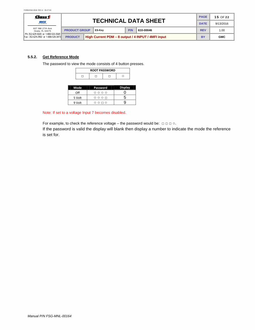
5.5.2. Get Reference Mode
The password to view the mode consists of 4 button presses.
ROOT PASSWORD
□ □ □ ○
Note: If set to a voltage Input 7 becomes disabled. For example, to check the reference voltage – the password would be: □ □ □ ○. If the password is valid the display will blank then display a number to indicate the mode the reference is set for.
Mode Password Display
Off ○ ○ ○ ○ 0 5 Volt ○ ○ ○ □ 5 9 Volt ○ ○ □ ○ 9

FORM-ENG-0018 REV A 05-27-03
607 NW 27th Ave Ocala, FL 34475
Ph: 352-629-5020 or 1-800-533-3569 Fax : 352-629-2902 or 1-800-520-3473
TECHNICAL DATA SHEET PAGE 16 OF 22
DATE 9/13/2016
PRODUCT GROUP ES-Key P/N 610-00046 REV 1.00
PRODUCT High Current PDM – 8 output / 4 INPUT / 4MFI input BY GMC
Manual P/N FSG-MNL-00164
5.6. Address configuration
The High Current PDM’s address can be set to any of the valid ES-Key addresses (0 through 15). Address 14 cannot be used if the device type is the default PDM (device type 1) because this device type/address combination is reserved for the ES-Key USM’s use. The password to set the address consists of 8 button presses. The root password is the first 4 button presses (○ ○ □ □) and the remaining 4 button presses indicate the desired address in binary coded decimal.
ROOT PASSWORD ADDRESS
○ ○ □ □ □ or ○ □ or ○ □ or ○ □ or ○ Address Password
Address Password
0 ○ ○ ○ ○
8 □ ○ ○ ○ 1 ○ ○ ○ □
9 □ ○ ○ □
2 ○ ○ □ ○
10 □ ○ □ ○ 3 ○ ○ □ □
11 □ ○ □ □
4 ○ □ ○ ○
12 □ □ ○ ○ 5 ○ □ ○ □
13 □ □ ○ □
6 ○ □ □ ○
14 □ □ □ ○ 7 ○ □ □ □
15 □ □ □ □
The address may be viewed at anytime during normal operation on the High Density PDM’s display.
5.7. Device Type configuration The High Current PDM’s device type can be set as an Input Output Module (IOM, device type 4) or a Power Distribution Module (PDM, device type 1). The High Density PDM’s default device type is a Power Distribution Module.
5.7.1. Set device type
Set the High Density PDM to Power Distribution Module device type.
ROOT PASSWORD PDM DEVICE TYPE
○ □ ○ ○ ○ ○ ○ □ Set the High Density PDM to Input Output Module device type.
ROOT PASSWORD IOM DEVICE TYPE
○ □ ○ ○ ○ □ ○ ○
5.7.2. View device type
The password to view the configured device type consists of 4 button presses.
ROOT PASSWORD
○ □ ○ □ After entering the “view device type” password the High Current PDM’s display will flash a number corresponding to the device type for 2.5 seconds. A number 1 is a Power Distribution Module (PDM), and a number 4 is an Input Output Module (IOM). The High Current PDM returns to normal operation after flashing the configured device type.

FORM-ENG-0018 REV A 05-27-03
607 NW 27th Ave Ocala, FL 34475
Ph: 352-629-5020 or 1-800-533-3569 Fax : 352-629-2902 or 1-800-520-3473
TECHNICAL DATA SHEET PAGE 17 OF 22
DATE 9/13/2016
PRODUCT GROUP ES-Key P/N 610-00046 REV 1.00
PRODUCT High Current PDM – 8 output / 4 INPUT / 4MFI input BY GMC
Manual P/N FSG-MNL-00164
5.8. Load defaults
The High Density PDM’s default configuration may be reloaded at anytime by entering a password.
ROOT PASSWORD LOAD DEFAULTS
□ ○ ○ ○ □ □ □ ○ ○ □ ○ □ The High Density PDM’s default configurations are:
Input polarity for all inputs: Positive Device type: Power Distribution Module, device type 1 Device address: 0 Circuit protection over-current level for all outputs: 31 Amps

FORM-ENG-0018 REV A 05-27-03
607 NW 27th Ave Ocala, FL 34475
Ph: 352-629-5020 or 1-800-533-3569 Fax : 352-629-2902 or 1-800-520-3473
TECHNICAL DATA SHEET PAGE 18 OF 22
DATE 9/13/2016
PRODUCT GROUP ES-Key P/N 610-00046 REV 1.00
PRODUCT High Current PDM – 8 output / 4 INPUT / 4MFI input BY GMC
Manual P/N FSG-MNL-00164
6. Mounting and Installation 6.1. Overall dimensions
Figure 6. Overall dimensions in inches [millimeters].
6.2. Mounting dimensions Mount the High Current PDM with four screws and nuts.
Figure 7. Installation dimensions in inches [millimeters].

FORM-ENG-0018 REV A 05-27-03
607 NW 27th Ave Ocala, FL 34475
Ph: 352-629-5020 or 1-800-533-3569 Fax : 352-629-2902 or 1-800-520-3473
TECHNICAL DATA SHEET PAGE 19 OF 22
DATE 9/13/2016
PRODUCT GROUP ES-Key P/N 610-00046 REV 1.00
PRODUCT High Current PDM – 8 output / 4 INPUT / 4MFI input BY GMC
Manual P/N FSG-MNL-00164
7. Connector Descriptions
7.1. Gray connector
Mating connector: Deutsch DT06-12SA GRAY Mating sockets: Deutsch 0462-201-16141 Gold mating sockets: Deutsch 0462-201-1631 Recommended wire gage: 16-20 AWG Wedge lock: W12S PIN CIRCUIT DESCRIPTION
1 INPUT 0 (INPUT) – Positive/Ground polarity (configurable)(MFI)
2 CAN HIGH (DATA) – SAE J1939 CAN 2.0B, 250Kbits/s *
3 CAN SHIELD (DATA) – SAE J1939 CAN 2.0B, 250Kbits/s *
4 INPUT 2 (INPUT) – Positive/Ground polarity (configurable)(MFI)
5 INPUT 4 (INPUT) – Positive/Ground polarity (configurable)
6 INPUT 6 (INPUT) – Positive/Ground polarity (configurable)
7 INPUT 7 (INPUT) – Positive/Ground polarity (configurable)
8 INPUT 5 (INPUT) – Positive/Ground polarity (configurable)
9 INPUT 3 (INPUT) – Positive/Ground polarity (configurable)(MFI)
10 INPUT 1 (INPUT) – Positive/Ground polarity (configurable)(MFI)
11 CAN LOW (DATA) – SAE J1939 CAN 2.0B, 250Kbits/s *
12 SYS GROUND (INPUT) – battery ground
* Gold sockets recommended for CAN connections.
7.2. Black connector (Middle)
Mating connector: Deutsch DTP06-4S GREY DTP06-4S-E004 BLACK Mating sockets: Deutsch 0462-203-12141 Recommended wire gage: 10-12 AWG Wedge lock: WP4S PIN CIRCUIT DESCRIPTION
1 OUTPUT 0 (OUTPUT) – Positive polarity (30 Amps)
2 OUTPUT 1 (OUTPUT) – Positive polarity (30 Amps)
3 OUTPUT 2 (OUTPUT) – Positive polarity (30 Amps)
4 OUTPUT 3 (OUTPUT) – Positive polarity (30 Amps)
7.3. Black connector
Mating connector: Deutsch DTP06-4S GREY DTP06-4S-E004 BLACK Mating sockets: Deutsch 0462-203-12141 Recommended wire gage: 10-12 AWG Wedge lock: WP4S PIN CIRCUIT DESCRIPTION
1 OUTPUT 4 (OUTPUT) – Positive polarity (30 Amps)
2 OUTPUT 5 (OUTPUT) – Positive polarity (30 Amps)
3 OUTPUT 6 (OUTPUT) – Positive polarity (30 Amps)
4 OUTPUT 7 (OUTPUT) – Positive polarity (30 Amps)

FORM-ENG-0018 REV A 05-27-03
607 NW 27th Ave Ocala, FL 34475
Ph: 352-629-5020 or 1-800-533-3569 Fax : 352-629-2902 or 1-800-520-3473
TECHNICAL DATA SHEET PAGE 20 OF 22
DATE 9/13/2016
PRODUCT GROUP ES-Key P/N 610-00046 REV 1.00
PRODUCT High Current PDM – 8 output / 4 INPUT / 4MFI input BY GMC
Manual P/N FSG-MNL-00164
7.4. High power connector
Mating connector: Cannon 121583-0013 Mating socket: Cannon 031-8521-020 (2 AWG) Cannon 031-8521-010 (4 AWG) Hexagonal nut: Cannon 217-8516-010 Cable seal: Cannon 351-8697-001 0.409 in – 0.472 in [10.4mm – 12.0mm] Recommended wire gage: 2 AWG For more information - Cannon website: http://www.ittcannon.com PIN CIRCUIT DESCRIPTION
1 OUTPUT PWR (INPUT) – battery voltage (+9VDC…+32VDC) *
The output power feed line should be fused to limit current to 200 Amps maximum.
FORM-ENG-0018 REV A 05-27-03
607 NW 27th Ave Ocala, FL 34475
Ph: 352-629-5020 or 1-800-533-3569 Fax : 352-629-2902 or 1-800-520-3473
TECHNICAL DATA SHEET PAGE 21 OF 22
DATE 9/13/2016
PRODUCT GROUP ES-Key P/N 610-00046 REV 1.00
PRODUCT High Current PDM – 8 output / 4 INPUT / 4MFI input BY GMC
Manual P/N FSG-MNL-00164
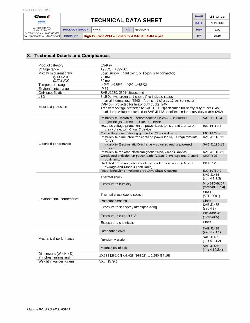
8. Technical Details and Compliances
Product category ES-Key Voltage range +9VDC…+32VDC Maximum current draw @13.8VDC @27.6VDC
Logic supply+ input (pin 1 of 12-pin gray connector) 73 mA 82 mA
Temperature range -40ºF…+185ºF (-40ºC…+85ºC) Environmental range IP 67 CAN specification SAE J1939, 250 Kbits/second LED 3 LEDs (two green and one red) to indicate status
Electrical protection
Internal thermal fuse (2500 mA on pin 1 of gray 12-pin connector) CAN bus protected for heavy duty trucks (24V) Transient voltage protected to SAE J1113 specification for heavy duty trucks (24V) Load dump voltage protected to SAE J1113 specification for heavy duty trucks (24V)
Electrical performance
Immunity to Radiated Electromagnetic Fields– Bulk Current Injection (BCI) method, Class C device
SAE J1113-4
Reverse voltage protection on power leads (pins 1 and 2 of 12-pin gray connector), Class C device
ISO 16750-2
Overvoltage due to failing generator, Class A device ISO 16750-2 Immunity to conducted transients on power leads, L4 requirements
(24V) SAE J1113-11
Immunity to Electrostatic Discharge – powered and unpowered modes
SAE J1113-13
Immunity to radiated electromagnetic fields, Class C device SAE J1113-21 Conducted emission on power leads (Class 3 average and Class 5
peak limits) CISPR 25
Radiated emissions, absorber-lined shielded enclosure (Class 1 average and Class 3 peak limits)
CISPR 25
Reset behavior on voltage drop 24V, Class C device ISO 16750-2
Environmental performance
Thermal shock SAE J1455 (sec 4.1.3.2)
Exposure to humidity
MIL-STD-810F (method 507.4)
Thermal shock due to splash Class 1 (STD-0001)
Pressure cleaning Class 1
Exposure to salt spray atmosphere/fog SAE J1455 (sec 4.3)
Exposure to outdoor UV ISO 4892-2 (method A)
Exposure to chemicals Class 1
Mechanical performance
Resonance dwell SAE J1455 (sec 4.9.4.1)
Random vibration SAE J1455 (sec 4.9.4.2)
Mechanical shock SAE J1455 (sec 4.10.3.4)
Dimensions (W x H x D) in inches [millimeters] 10.313 [261.94] x 6.625 [168.28] x 2.250 [57.15]
Weight in ounces [grams] 55.7 [1579.1]

FORM-ENG-0018 REV A 05-27-03
607 NW 27th Ave Ocala, FL 34475
Ph: 352-629-5020 or 1-800-533-3569 Fax : 352-629-2902 or 1-800-520-3473
TECHNICAL DATA SHEET PAGE 22 OF 22
DATE 9/13/2016
PRODUCT GROUP ES-Key P/N 610-00046 REV 1.00
PRODUCT High Current PDM – 8 output / 4 INPUT / 4MFI input BY GMC
Manual P/N FSG-MNL-00164
9. References
9.1. List of figures
FIGURE 1. HIGH DENSITY PDM INDICATORS AND BUTTONS. ................................................................................................. 4 FIGURE 2. HIGH DENSITY PDM DISPLAY. ........................................................................................................................... 5 FIGURE 3. HIGH DENSITY PDM LED INDICATORS. .............................................................................................................. 6 FIGURE 4. HIGH DENSITY PDM BUTTONS. .......................................................................................................................... 7 FIGURE 5. OUTPUT BANKS A AND B FLASH RATES. .............................................................................................................. 8 FIGURE 6. OVERALL DIMENSIONS IN INCHES [MILLIMETERS]. ................................................................................................18 FIGURE 7. INSTALLATION DIMENSIONS IN INCHES [MILLIMETERS]. ..........................................................................................18
9.2. List of tables
TABLE 1. NORMAL OPERATION ADDRESS DISPLAY. ............................................................................................................... 5 TABLE 2. SYSTEM PWR LED STATES. ............................................................................................................................ 6 TABLE 3. DRIVER PWR LED STATES. ............................................................................................................................. 6 TABLE 4. COM LED STATES. ........................................................................................................................................... 6 TABLE 5. FLASH LOGIC. .................................................................................................................................................... 9 TABLE 6. PWM LOGIC. ....................................................................................................................................................10 TABLE 7. STANDARD I/O MEMORY SPACE. .........................................................................................................................11 TABLE 8. PASSWORD LIST. ...............................................................................................................................................12