technical operations manual (tom) - turtle...
TRANSCRIPT

TECHNICAL OPERATIONS MANUAL (TOM)for
COMPOSITE CRIBBING“Lift an inch, crib an inch”
—CONTENTS—Introduction
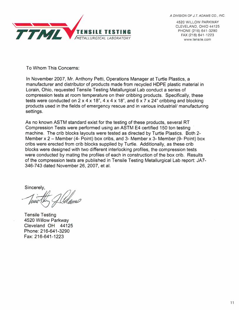
Army Corps of Engineers Shoring Operations GuideTensile Testing Lab Reports (Independent Lab)
Safety Data Sheets (MSDS)Chemical Resistance Sheets
MiscellaneousInstruction Sheet
PREPARED BY TURTLE PLASTICS
2
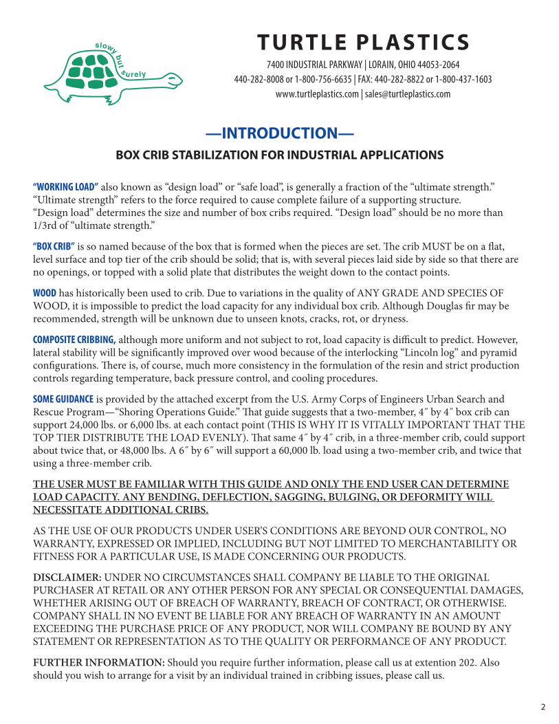
—INTRODUCTION—BOX CRIB STABILIZATION FOR INDUSTRIAL APPLICATIONS
TURTLE PLASTICS7400 INDUSTRIAL PARKWAY | LORAIN, OHIO 44053-2064
440-282-8008 or 1-800-756-6635 | FAX: 440-282-8822 or 1-800-437-1603www.turtleplastics.com | [email protected]
“WORKING LOAD” also known as “design load” or “safe load”, is generally a fraction of the “ultimate strength.” “Ultimate strength” refers to the force required to cause complete failure of a supporting structure. “Design load” determines the size and number of box cribs required. “Design load” should be no more than1/3rd of “ultimate strength.”
“BOX CRIB” is so named because of the box that is formed when the pieces are set. e crib MUST be on a flat,level surface and top tier of the crib should be solid; that is, with several pieces laid side by side so that there areno openings, or topped with a solid plate that distributes the weight down to the contact points.
WOOD has historically been used to crib. Due to variations in the quality of ANY GRADE AND SPECIES OFWOOD, it is impossible to predict the load capacity for any individual box crib. Although Douglas fir may berecommended, strength will be unknown due to unseen knots, cracks, rot, or dryness.
COMPOSITE CRIBBING, although more uniform and not subject to rot, load capacity is difficult to predict. However,lateral stability will be significantly improved over wood because of the interlocking “Lincoln log” and pyramidconfigurations. ere is, of course, much more consistency in the formulation of the resin and strict productioncontrols regarding temperature, back pressure control, and cooling procedures.
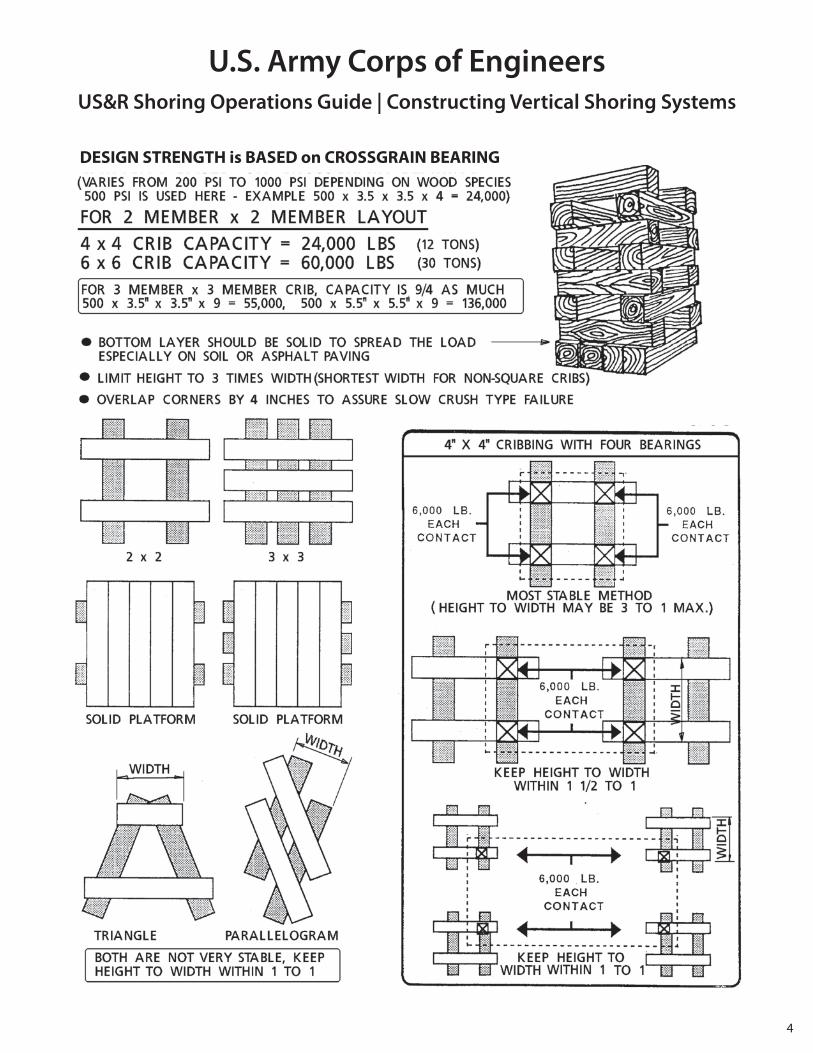
SOME GUIDANCE is provided by the attached excerpt from the U.S. Army Corps of Engineers Urban Search and Rescue Program—“Shoring Operations Guide.” at guide suggests that a two-member, 4˝ by 4˝ box crib cansupport 24,000 lbs. or 6,000 lbs. at each contact point (THIS IS WHY IT IS VITALLY IMPORTANT THAT THETOP TIER DISTRIBUTE THE LOAD EVENLY). at same 4˝ by 4˝ crib, in a three-member crib, could supportabout twice that, or 48,000 lbs. A 6˝ by 6˝ will support a 60,000 lb. load using a two-member crib, and twice thatusing a three-member crib.
THE USER MUST BE FAMILIAR WITH THIS GUIDE AND ONLY THE END USER CAN DETERMINELOAD CAPACITY. ANY BENDING, DEFLECTION, SAGGING, BULGING, OR DEFORMITY WILL NECESSITATE ADDITIONAL CRIBS.
AS THE USE OF OUR PRODUCTS UNDER USER’S CONDITIONS ARE BEYOND OUR CONTROL, NOWARRANTY, EXPRESSED OR IMPLIED, INCLUDING BUT NOT LIMITED TO MERCHANTABILITY ORFITNESS FOR A PARTICULAR USE, IS MADE CONCERNING OUR PRODUCTS.
DISCLAIMER: UNDER NO CIRCUMSTANCES SHALL COMPANY BE LIABLE TO THE ORIGINAL PURCHASER AT RETAIL OR ANY OTHER PERSON FOR ANY SPECIAL OR CONSEQUENTIAL DAMAGES,WHETHER ARISING OUT OF BREACH OF WARRANTY, BREACH OF CONTRACT, OR OTHERWISE.COMPANY SHALL IN NO EVENT BE LIABLE FOR ANY BREACH OF WARRANTY IN AN AMOUNT EXCEEDING THE PURCHASE PRICE OF ANY PRODUCT, NOR WILL COMPANY BE BOUND BY ANYSTATEMENT OR REPRESENTATION AS TO THE QUALITY OR PERFORMANCE OF ANY PRODUCT.
FURTHER INFORMATION: Should you require further information, please call us at extention 202. Alsoshould you wish to arrange for a visit by an individual trained in cribbing issues, please call us.
36.5 in.5.5 in.
5.5 in.
3
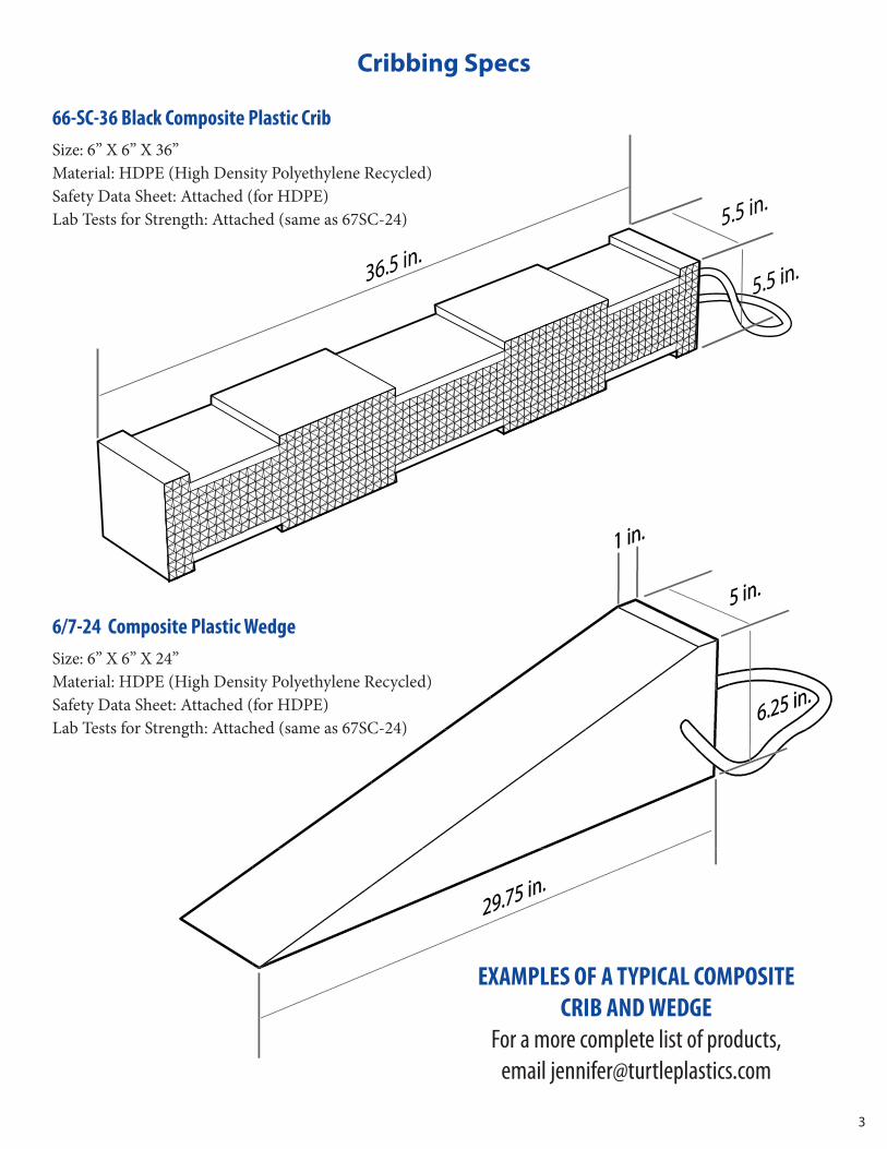
Cribbing Specs
EXAMPLES OF A TYPICAL COMPOSITE CRIB AND WEDGE
For a more complete list of products, email [email protected]
66-SC-36 Black Composite Plastic CribSize: 6” X 6” X 36”Material: HDPE (High Density Polyethylene Recycled)Safety Data Sheet: Attached (for HDPE)Lab Tests for Strength: Attached (same as 67SC-24)
6/7-24 Composite Plastic WedgeSize: 6” X 6” X 24”Material: HDPE (High Density Polyethylene Recycled)Safety Data Sheet: Attached (for HDPE)Lab Tests for Strength: Attached (same as 67SC-24)
4
U.S. Army Corps of EngineersUS&R Shoring Operations Guide | Constructing Vertical Shoring Systems
DESIGN STRENGTH is BASED on CROSSGRAIN BEARING
5
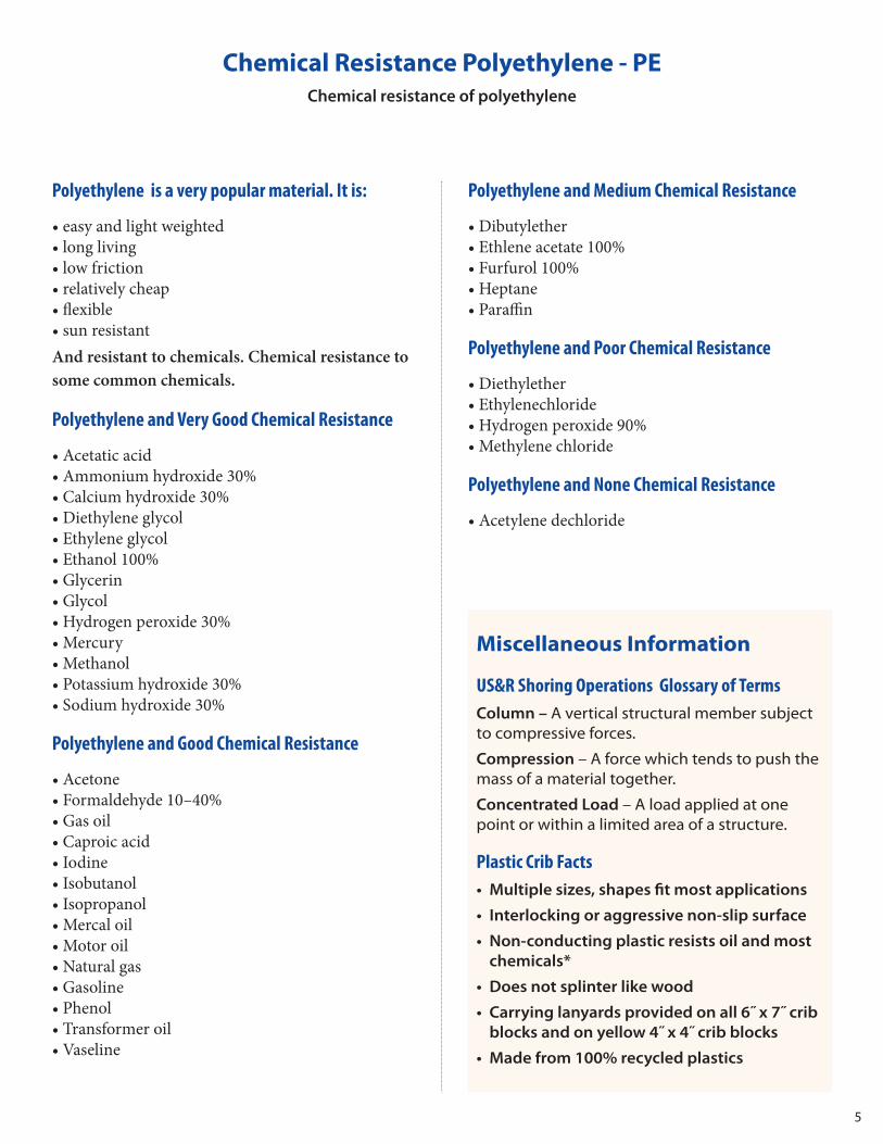
Chemical Resistance Polyethylene - PEChemical resistance of polyethylene
Miscellaneous Information
US&R Shoring Operations Glossary of TermsColumn – A vertical structural member subjectto compressive forces.
Compression – A force which tends to push themass of a material together.
Concentrated Load – A load applied at onepoint or within a limited area of a structure.
Plastic Crib Facts• Multiple sizes, shapes fit most applications
• Interlocking or aggressive non-slip surface
• Non-conducting plastic resists oil and mostchemicals*
• Does not splinter like wood
• Carrying lanyards provided on all 6˝ x 7˝ cribblocks and on yellow 4˝ x 4˝ crib blocks
• Made from 100% recycled plastics
Polyethylene is a very popular material. It is:
• easy and light weighted• long living• low friction• relatively cheap• flexible• sun resistantAnd resistant to chemicals. Chemical resistance tosome common chemicals.
Polyethylene and Very Good Chemical Resistance
• Acetatic acid• Ammonium hydroxide 30%• Calcium hydroxide 30%• Diethylene glycol• Ethylene glycol• Ethanol 100%• Glycerin• Glycol• Hydrogen peroxide 30%• Mercury• Methanol• Potassium hydroxide 30%• Sodium hydroxide 30%
Polyethylene and Good Chemical Resistance
• Acetone• Formaldehyde 10–40%• Gas oil• Caproic acid• Iodine• Isobutanol• Isopropanol• Mercal oil• Motor oil• Natural gas• Gasoline• Phenol• Transformer oil• Vaseline
Polyethylene and Medium Chemical Resistance
• Dibutylether• Ethlene acetate 100%• Furfurol 100%• Heptane• Paraffin
Polyethylene and Poor Chemical Resistance
• Diethylether• Ethylenechloride• Hydrogen peroxide 90%• Methylene chloride
Polyethylene and None Chemical Resistance
• Acetylene dechloride
6
Composite Crib Instruction Sheet
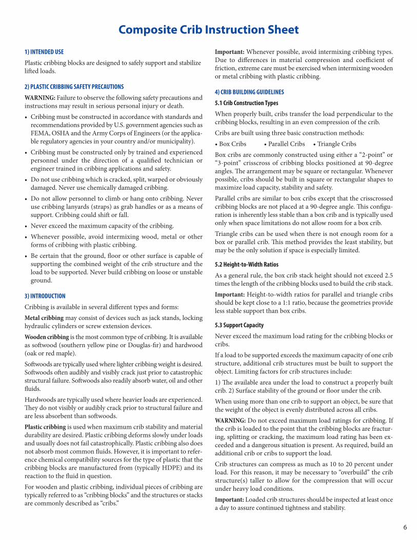
1) INTENDED USE
Plastic cribbing blocks are designed to safely support and stabilizelied loads.
2) PLASTIC CRIBBING SAFETY PRECAUTIONS
WARNING: Failure to observe the following safety precautions andinstructions may result in serious personal injury or death.• Cribbing must be constructed in accordance with standards and
recommendations provided by U.S. government agencies such asFEMA, OSHA and the Army Corps of Engineers (or the applica-ble regulatory agencies in your country and/or municipality).
• Cribbing must be constructed only by trained and experiencedpersonnel under the direction of a qualified technician or engineer trained in cribbing applications and safety.
• Do not use cribbing which is cracked, split, warped or obviouslydamaged. Never use chemically damaged cribbing.
• Do not allow personnel to climb or hang onto cribbing. Neveruse cribbing lanyards (straps) as grab handles or as a means ofsupport. Cribbing could shi or fall.
• Never exceed the maximum capacity of the cribbing.• Whenever possible, avoid intermixing wood, metal or other
forms of cribbing with plastic cribbing.• Be certain that the ground, floor or other surface is capable of
supporting the combined weight of the crib structure and theload to be supported. Never build cribbing on loose or unstableground.
3) INTRODUCTION
Cribbing is available in several different types and forms:Metal cribbing may consist of devices such as jack stands, lockinghydraulic cylinders or screw extension devices.Wooden cribbing is the most common type of cribbing. It is availableas sowood (southern yellow pine or Douglas-fir) and hardwood(oak or red maple).Sowoods are typically used where lighter cribbing weight is desired.Sowoods oen audibly and visibly crack just prior to catastrophicstructural failure. Sowoods also readily absorb water, oil and otherfluids.Hardwoods are typically used where heavier loads are experienced.ey do not visibly or audibly crack prior to structural failure andare less absorbent than sowoods.Plastic cribbing is used when maximum crib stability and materialdurability are desired. Plastic cribbing deforms slowly under loadsand usually does not fail catastrophically. Plastic cribbing also doesnot absorb most common fluids. However, it is important to refer-ence chemical compatibility sources for the type of plastic that thecribbing blocks are manufactured from (typically HDPE) and itsreaction to the fluid in question.For wooden and plastic cribbing, individual pieces of cribbing aretypically referred to as “cribbing blocks” and the structures or stacksare commonly described as “cribs.”
Important: Whenever possible, avoid intermixing cribbing types.Due to differences in material compression and coefficient of friction, extreme care must be exercised when intermixing woodenor metal cribbing with plastic cribbing.
4) CRIB BUILDING GUIDELINES
5.1 Crib Construction Types
When properly built, cribs transfer the load perpendicular to thecribbing blocks, resulting in an even compression of the crib.Cribs are built using three basic construction methods:• Box Cribs • Parallel Cribs • Triangle CribsBox cribs are commonly constructed using either a “2-point” or“3-point” crisscross of cribbing blocks positioned at 90-degree angles. e arrangement may be square or rectangular. Wheneverpossible, cribs should be built in square or rectangular shapes tomaximize load capacity, stability and safety.Parallel cribs are similar to box cribs except that the crisscrossedcribbing blocks are not placed at a 90-degree angle. is configu-ration is inherently less stable than a box crib and is typically usedonly when space limitations do not allow room for a box crib.Triangle cribs can be used when there is not enough room for abox or parallel crib. is method provides the least stability, butmay be the only solution if space is especially limited.
5.2 Height-to-Width Ratios
As a general rule, the box crib stack height should not exceed 2.5times the length of the cribbing blocks used to build the crib stack. Important: Height-to-width ratios for parallel and triangle cribsshould be kept close to a 1:1 ratio, because the geometries provideless stable support than box cribs.
5.3 Support Capacity
Never exceed the maximum load rating for the cribbing blocks orcribs.If a load to be supported exceeds the maximum capacity of one cribstructure, additional crib structures must be built to support theobject. Limiting factors for crib structures include:1) e available area under the load to construct a properly builtcrib. 2) Surface stability of the ground or floor under the crib.When using more than one crib to support an object, be sure thatthe weight of the object is evenly distributed across all cribs.WARNING: Do not exceed maximum load ratings for cribbing. Ifthe crib is loaded to the point that the cribbing blocks are fractur-ing, splitting or cracking, the maximum load rating has been ex-ceeded and a dangerous situation is present. As required, build anadditional crib or cribs to support the load.Crib structures can compress as much as 10 to 20 percent underload. For this reason, it may be necessary to “overbuild” the cribstructure(s) taller to allow for the compression that will occurunder heavy load conditions.Important: Loaded crib structures should be inspected at least oncea day to assure continued tightness and stability.

7
Excessive heat can cause the plastic cribbing material to creep, resulting in diminished load carrying capacity. Extreme cold cancause the cribbing material to fracture prematurely.
5.4 Crib Building - General Instructions
Plastic cribbing blocks contain both interlocking and pyramidalsurfaces. is allows two distinct methods for building crib stacks:1) Interlocking surface - Mechanically interlocking the cribbingblocks in pre-cast notches (all except 2˝ x 4˝ x 18˝ size) helps ensuremaximum structural integrity. Using the “box crib” method, crib-bing blocks are stacked at 90-degree angles. .2) Pyramid surface - When constructing parallel and triangle cribs,a combination of gravity and surface friction maintains the struc-ture. Using this method, cribbing blocks may be stacked at anglesother than 90 degrees. On the 4˝ x 4˝ x 18˝ and 6˝ x 7˝ x 24˝ sizes, the blocks can bearranged using either the pyramidal (pyramid textured) or inter-locking (notched) sides as the weight-bearing surface. When build-ing a crib that does not have a rectangular shape, the pyramidalsurface must be used as the weight-bearing surface.When using the pyramidal surface, ensure that there is sufficientoverlap at the crib corners. Corners of the crib should overlap bythe longest dimension of the crib face that is being loaded. is willassure the desired failure mode (characteristics) in the event thatthe crib is overloaded.WARNING: Be certain that the crib structure will be capable ofholding the total weight of the object being supported. Build addi-tional crib structures if required to adequately support the totalweight of the object.WARNING: Do not build a non-rectangular crib that is more than20 degrees out-of-square. Without a mechanical stop, friction andgravity will not hold the crib together.All cribs must be positioned on a flat and stable surface. When nec-essary, wedges must be used to help stabilize and level the crib sothat when loaded, the top surface is level.Li the object to be cribbed in a safe manner, using appropriateliing devices. Whenever possible, build the crib to the desiredheight and then li the object in place on top of the crib. If this isnot possible, use the stage liing method (“li an inch, crib aninch”) to build the crib.WARNING: Never work under an object that is not supported by asufficiently robust crib structure.
5.5 Shoring (Supporting a Sloped Load)
Whenever possible, the load should be positioned perpendicularto the top surface of the crib. However, if the load must remainsloped, build the cribbing into the load using thinner cribbingblocks and/or wedges.Always observe the following requirements when shoring slopedloads using plastic cribbing blocks:1) e load should be centered on the middle third of the cribstructure to ensure stability and load transfer into the floor orground. 2) Slope force must be resisted by friction. 3) e base layer of the crib structure must be solid.
5.6 Chocking (Supporting a Load that is Not Flat)
Objects that are not flat can be supported by a crib. However, theymust be properly chocked or wedged in place to eliminate unde-sired lateral movement.NOTE: e Shoring Operations Guide (SOG), published by the U.S.Army Corps of Engineers, is a suggested reference. It contains detailed instructions, recommendations and precautions regardingproper shoring and chocking procedures.
5) INSPECTION
It is strongly recommended that the cribbing blocks be inspectedbefore and aer each use. Refer to the following steps:1. Inspect the cribbing blocks for cuts, gouges and other visible
damage. Do not use blocks with obvious structural damage.2. Cribbing blocks will compress and retain the set. If compression
exceeds 20 percent of the cribbing block cross dimension, or isgreater than 2 inches [50 mm], closely inspect for fractures, splitsor cracks.
3. If a cribbing block fractures during use so that splits and cracksare visible, mark the damaged cribbing block and (if safety allows)remove it from service at the earliest possible time. e load willfirst need to be removed from the crib so the block can be replaced.
4. Cribbing blocks damaged by chemical exposure should be re-moved from service. Recycle or properly dispose of such blocks.Swelling, melting, powder residue or other non-mechanicaldamage is evidence of chemical exposure.
Important: Keep chemically exposed cribbing blocks in a separatearea to avoid migration of the attacking chemical into other non-contaminated cribbing blocks.
6) CLEANING
e cribbing blocks can be power washed to remove grit and dirtfrom their surfaces.If foreign materials have become ground into the crib surface, or ifthe surface contains abrasions, cracks or cuts, the cribbing blockshould be removed from service and recycled.Contaminated cribbing blocks that cannot be cleaned should beremoved from service and disposed of.
7) STORAGE
To prolong their usable service life, store the cribbing blocks in a cool,dry area in an unloaded state. Do not store cribbing blocks outdoors.Protect the cribbing blocks from freeze-thaw cycles. Store theblocks away from direct sunlight and other sources of ultraviolet(UV) radiation.
8) RECYCLING
Cribbing blocks are manufactured from recycled high-densitypolyethylene (HDPE) and small amounts of polypropylene (PP).Contact your local recycler to dispose of damaged and unusablecribbing blocks.
8
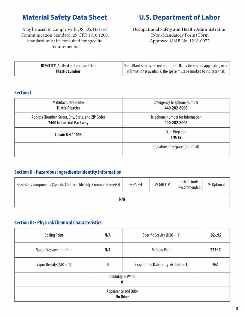
IDENTITY (As Used on Label and List)Plastic Lumber
Note: Blank spaces are not permitted. If any item is not applicable, or noinformation is available, the space must be marked to indicate that.
Material Safety Data Sheet
May be used to comply with OSHA’s Hazard Communication Standard, 29 CFR 1910.1200.
Standard must be consulted for specific requirements.
U.S. Department of Labor
Occupational Safety and Health Administration (Non-Mandatory Form) Form Approved OMB No. 1218-0072
Manufacturer’s NameTurtle Plastics
Emergency Telephone Number440-282-8008
Address (Number, Street, City, State, and ZIP Code)7400 Industrial Parkway
Lorain OH 44053
Section I
Telephone Number for Information440-282-8008
Date Prepared1/9/12
Signature of Preparer (optional)
Hazardous Components (Specific Chemical Identity; Common Name(s))
N/A
OSHA PEL ACGIH TLV Other LimitsRecommended % Optional
Section II • Hazardous Ingredients/Identity Information
Boiling Point N/A Specific Gravity (H2O = 1) .92-.95
Vapor Pressure (mm Hg) N/A Melting Point 225º C
Vapor Density (AIR = 1)
Solubility in Water0
Appearance and OdorNo Odor
0 Evaporation Rate (Butyl Acetate = 1) N/A
Section III • Physical/Chemical Characteristics
9
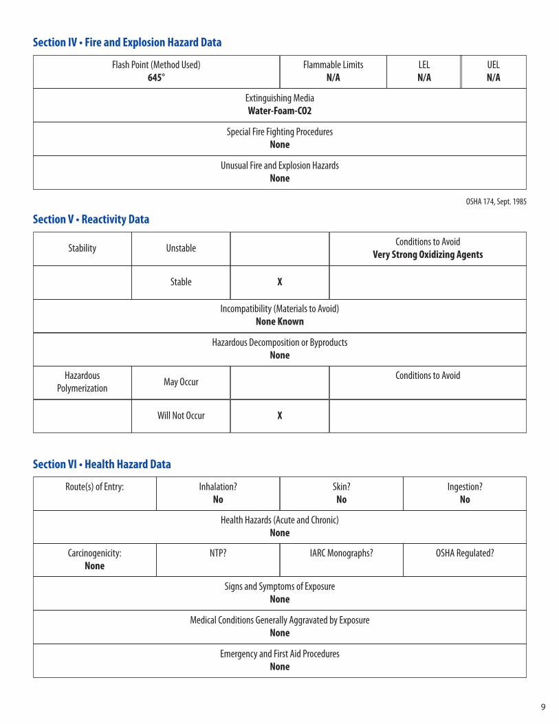
Flash Point (Method Used)645°
Extinguishing MediaWater-Foam-CO2
Special Fire Fighting ProceduresNone
Unusual Fire and Explosion HazardsNone
Flammable LimitsN/A
LELN/A
UELN/A
Section IV • Fire and Explosion Hazard Data
Incompatibility (Materials to Avoid)None Known
Hazardous Decomposition or ByproductsNone
Stability Unstable Conditions to AvoidVery Strong Oxidizing Agents
Stable X
Section V • Reactivity Data
Hazardous Polymerization May Occur Conditions to Avoid
Will Not Occur X
Route(s) of Entry: Inhalation?No
Skin?No
Ingestion?No
Section VI • Health Hazard Data
Health Hazards (Acute and Chronic)None
Carcinogenicity:None
NTP? IARC Monographs? OSHA Regulated?
Signs and Symptoms of ExposureNone
Medical Conditions Generally Aggravated by ExposureNone
Emergency and First Aid ProceduresNone
OSHA 174, Sept. 1985

10
* U.S.G.P.O.: 1986 - 491 - 529/45775
Steps to Be Taken in Case Material is Released or SpilledAs the end product (lumber) – Collect and restack Raw Material – Collect back into box for use;
Saw Swarf (dust) – Brush up and dispose to landfill
Waste Disposal MethodDispose to sanitary landfill
Precautions to Be taken in Handling and StoringNo special precautions – Good housekeeping practice should be followed
Other PrecautionsNone
Section VII • Precautions for Safe Handling and Use
Respiratory Protection (Specify Type)N/A
Section VIII • Control Measures
Ventilation Local ExhaustWhen Cutting
SpecialNone
Mechanical (General)N/A
Protective GlovesWhen Cutting
Other Protective Clothing or EquipmentNone
Work/Hygienic PracticesNormal Hygiene
Eye ProtectionWhen Cutting
OtherNone
11
12
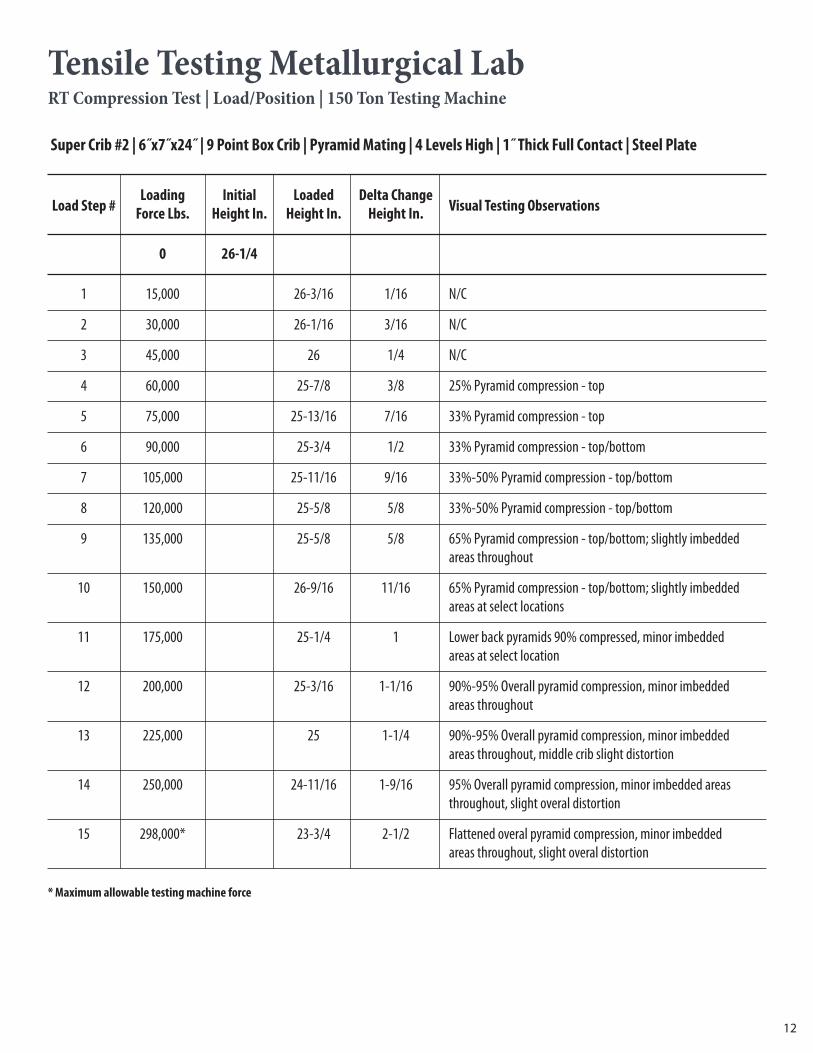
Tensile Testing Metallurgical LabRT Compression Test | Load/Position | 150 Ton Testing Machine
Super Crib #2 | 6˝x7˝x24˝ | 9 Point Box Crib | Pyramid Mating | 4 Levels High | 1˝ Thick Full Contact | Steel Plate
Load Step #Loading Initial Loaded Delta Change
Visual Testing ObservationsForce Lbs. Height In. Height In. Height In.
0 26-1/4
1 15,000 26-3/16 1/16 N/C
2 30,000 26-1/16 3/16 N/C
3 45,000 26 1/4 N/C
4 60,000 25-7/8 3/8 25% Pyramid compression - top
5 75,000 25-13/16 7/16 33% Pyramid compression - top
6 90,000 25-3/4 1/2 33% Pyramid compression - top/bottom
7 105,000 25-11/16 9/16 33%-50% Pyramid compression - top/bottom
8 120,000 25-5/8 5/8 33%-50% Pyramid compression - top/bottom
9 135,000 25-5/8 5/8 65% Pyramid compression - top/bottom; slightly imbeddedareas throughout
10 150,000 26-9/16 11/16 65% Pyramid compression - top/bottom; slightly imbeddedareas at select locations
11 175,000 25-1/4 1 Lower back pyramids 90% compressed, minor imbeddedareas at select location
12 200,000 25-3/16 1-1/16 90%-95% Overall pyramid compression, minor imbeddedareas throughout
13 225,000 25 1-1/4 90%-95% Overall pyramid compression, minor imbeddedareas throughout, middle crib slight distortion
14 250,000 24-11/16 1-9/16 95% Overall pyramid compression, minor imbedded areasthroughout, slight overal distortion
15 298,000* 23-3/4 2-1/2 Flattened overal pyramid compression, minor imbeddedareas throughout, slight overal distortion
* Maximum allowable testing machine force
13
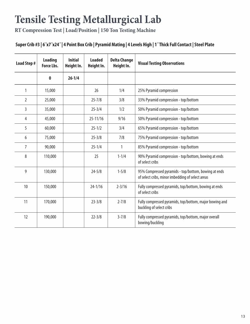
Tensile Testing Metallurgical LabRT Compression Test | Load/Position | 150 Ton Testing Machine
Super Crib #3 | 6˝x7˝x24˝ | 4 Point Box Crib | Pyramid Mating | 4 Levels High | 1˝ Thick Full Contact | Steel Plate
Load Step #Loading Initial Loaded Delta Change
Visual Testing ObservationsForce Lbs. Height In. Height In. Height In.
0 26-1/4
1 15,000 26 1/4 25% Pyramid compression
2 25,000 25-7/8 3/8 33% Pyramid compression - top/bottom
3 35,000 25-3/4 1/2 50% Pyramid compression - top/bottom
4 45,000 25-11/16 9/16 50% Pyramid compression - top/bottom
5 60,000 25-1/2 3/4 65% Pyramid compression - top/bottom
6 75,000 25-3/8 7/8 75% Pyramid compression - top/bottom
7 90,000 25-1/4 1 85% Pyramid compression - top/bottom
8 110,000 25 1-1/4 90% Pyramid compression - top/bottom, bowing at endsof select cribs
9 130,000 24-5/8 1-5/8 95% Compressed pyramids - top/bottom, bowing at endsof select cribs, minor imbedding of select areas
10 150,000 24-1/16 2-3/16 Fully compressed pyramids, top/bottom, bowing at endsof select cribs
11 170,000 23-3/8 2-7/8 Fully compressed pyramids, top/bottom, major bowing andbuckling of select cribs
12 190,000 22-3/8 3-7/8 Fully compressed pyramids, top/bottom, major overall bowing/buckling