technical notes 1978 4 300dpi r - scientific association · technical notes the bandwidth of a...
TRANSCRIPT
EISCAT
TECHNICAL
NOTES
THE BANDWIDTH OF A LINEAR PHASED ARRAY WITH
STEPPED DELAY CORRECTIONS
T. Hagfors
KIRUNASweden
78/4
EISCAT TECHNICAL NOTE No 4.
JANUARY 1978
THE BANDWIDTH OF A LINEAR PHASED ARRAY WITH
STEPPED DELAY CORRECTIONS
T. Hagfors
Summary.
The note discusses the bandwidth limitation which gradually
developes as the beam is phased away from that beam direction
which corresponds to the correct group delays. A scheme for the
increase in antenna bandwidth by introducing group delay cor
rections in steps along the antenna aperture is then discussed
and relations between the number of groups required for various
bandwidths are developed.
EISCAT SCI ENTIFIC ASSOCIATION5-98101 KIRUNA 1. SWEDENTELEPHONEc.I/ ll7 40
TELEX l7Ii4 OEOFVSK S
1.0 INTRODUCTION
The feed for a phased array cylindrical reflector VHF antenna
must be some 100 m long if the necessary effective aperture
is to be achieved. If the steering is done by phasing modulo
2n at the center frequency f O there will be some bandwidth
restrictions which may only be overcome by application of delay
corrections over sections of the line feed.
In what follows we shall study the bandwidth question both without
and with the delay corrections applied .
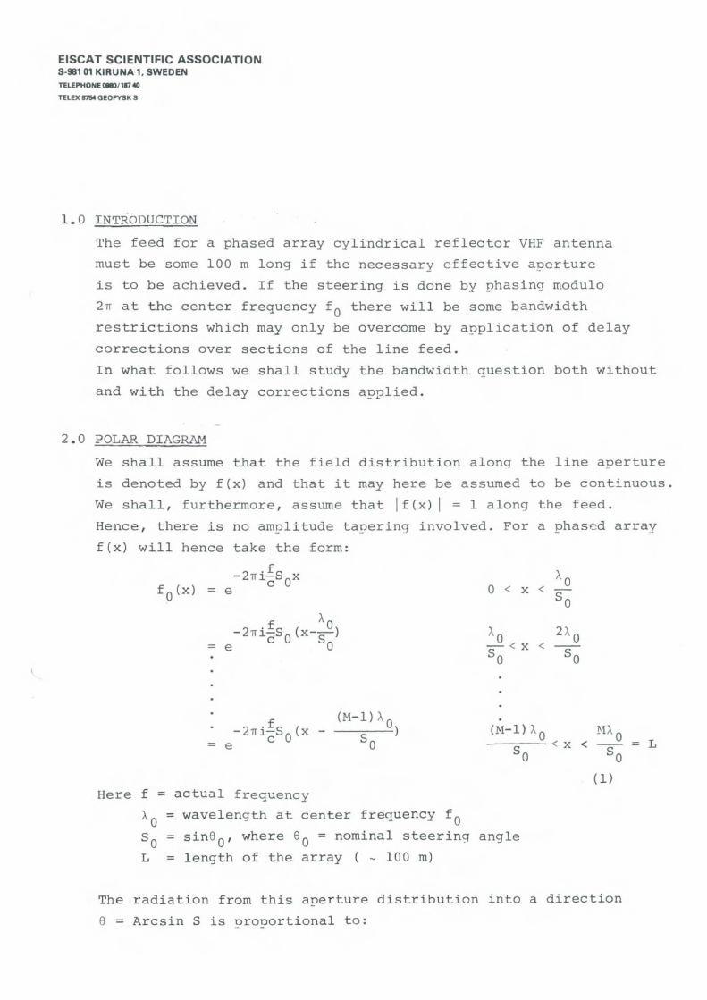
2 .0 POLAR DIAGRAM
We shall assume that the field distribution alonq the line aperture
is denoted by f(x) and that it may here be assumed to be continuous.
We shall , furthermore , assume that I f (x ) I = l along the feed .
Hence , there is no amplitude tapering involved . For a phased array
f(x) will hence take the form :
- 2n i i S xc O= e
f AO-2ni-S (x--)= e c O So
(M-l)AO
S )O
Here f = actual frequency
AO
= wave l e ng t h at center freque ncy f OS o = sin6 0 , where 60 = nomina l steerinq angle
L = l eng t h of t he array ( - 100 m)
MAO< -- = L
So
(l)
The radiation from this aperture distribution into a d irection
6 = Arc sin S is orooortional to :
.., -
EISCAT SCIENTIFIC ASSOCIATION5-98101 KIRUNA 1. 5WEDENTEUPHONE 011801117 40
TELEX l7'lI4 GEOFY SK S
L
f2niSx
F (S ) = dx' f (x) . e
O
fc ( 2)
With the particular form of f(x) given above one obtains :
sin(n!SL)cf 1. 0sin( n-S-)
~I
rs i.n ( 11"T
·- 0( 3)
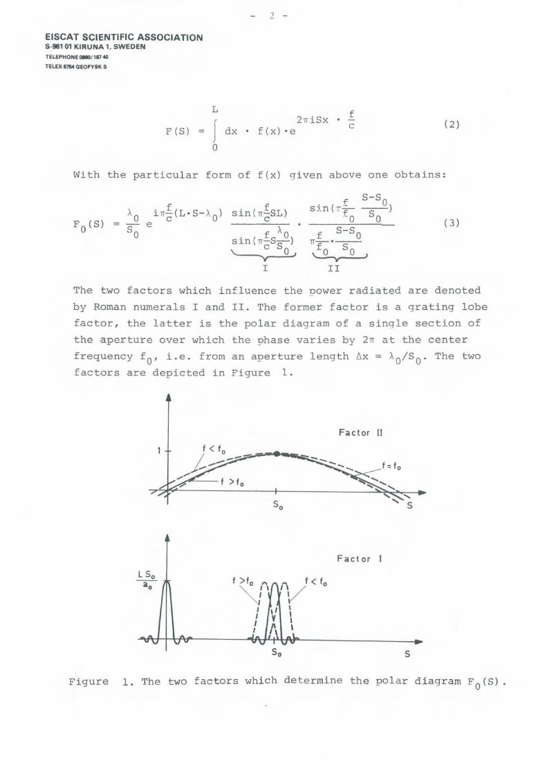
The two factors which influence the Dower radiated are denoted
by Roman numerals I and II. The former factor is agrating lobe
factor , the latter is the polar diagram of a single section of
the aperture over which the phase varies by 211" at the center
frequency f O' i.e. from an aperture length 6x = AO/ SO. The two
factors are depicted in Figure l.
Fac ta r II
F act a r I
f >fo '", \I,
IIII
S
Figure l . The two factors which determine the polar d iagram FO(S) .

EISCAT SCIENTIFIC ASSOCIATION5 ·98101 KIRUNA 1. 5WEO ENTEUPHONE~/117 40
TELD; 11M OEonSK S
Fo (S)
t <to
t > to
f >t t ,0-1
III,
3 - Jr
S
Figure 2 . Resulting polar diagram.
The bandwidth is determined from the followinq argument: If we
transmit at a frequency of f O and wish to receive at offset
frequencies (e .g . plasma lines) we must make certain that the
center of the offset frequency beams overlap the transmit
frequency beam sufficiently well . A useful criterion appears to
be that the center of the offset beams fall at the half-oower
point of the central beam:
IHf
O= (4)
with 65 = 1;4 • L:f according to the above criterion. Hence weO
obtain for the (half-) bandwidth :
IM I =1. 4 crrS 'LO
(5)
The bandwidth is shown as function of steerinq angle 8 0 = Arcsin5 0in Figure 3 for a feeder length of 100 m. It is apoarent from this
diagram that the bandwidth obtained by phasinq only is quite
adequate for ion-spectrum observations , but is c learly inadequate
fo r plasma line observat ions . Hence , i n the next section we shall
consider the problem of the delay correction in order to recover
the bandwidth required for plasma line observations.

4 -
EISCAT SCIENTIFIC ASSOCIATION5-98101 KIRUNA 1. 5WEDENTEUPHONE a.l/117 40
TELEX 1114 OEOFYSK S
~f
(MHz)
20
10
O 10 20 30 [.J8 0 = Ancsin So
Figure 3 . Half-bandwidth olotted against steering angle .
3 .0 DELAY CORRECTIONS
We shall now imagine that the line feed is broken up into m
equal sections and that a delay correction is ap~lied to each
section , the correction becoming progressively larger in steps
along the aperture . The situation is shown for m = 4 in Figure 4 .
Delay
x(4) L(3 )( 2)
-- - - r------J
o (1 )
Figure 4 . Delay corrections applied , m = 4.N·mA
Nominal correction : Sl = L O
Mathema t i c al l y t he delay correc t ions c a n be described b y a n
a perture f unctio n fl (x ) :
5 -
EISCAT SCIENTIFIC ASSOCIATION5 -98101 KIRUNA 1. 5WEDENTEUPHONE 01lI0/ 117 40
TELEX l7ll4 OEOFY8K S
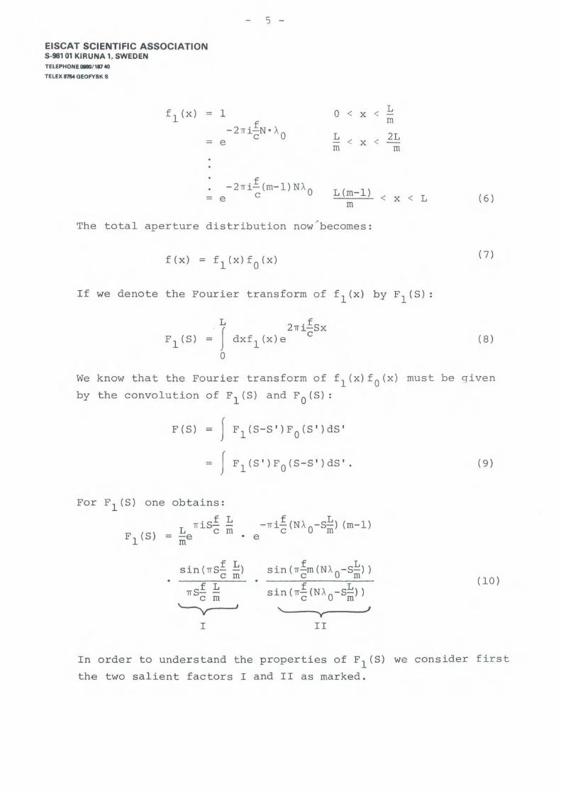
fl(x) = l O < < Lx
-2niiN ° Am
c O L < 2L= e - x <m m
-2 nii(m-l)NA= e c O L (m-l)
m< x < L (6 )
The total aperture distribution now~becomes:
If we denote the Fourier transform of fl(x) by Fl(S):
( 7)
L
f2ni~Sx
= dxfl(x)e
O
(8 )
We know that the Fourier trans form of fl(x)fO(x) must be given
by the convolution of Fl(S) and FO(S):
F (S) = J
= f
F (S-S')F (S ')dS 'l O
(9 )
Fl (S)
For Fl(S) one obtains :
.sf LL 1T J. C ffi
= -em
sin ( 1TSi ~)c m
I
s in ( 1T!m (N Ao-S~) )c m
'-......_--y--_....II
(la)
I n order to understand the properties of Fl(S) we consider first
the two salient factors I and II as marked .

6 -
EISCAT SCIENTIFIC ASSOCIATIONS -981 01 KIRUNA 1, SWEDENTELEPHONE a.D"17 40
TELEX 17M OEOFY8K 8
Factor I
-
Factor "
N
o
_______ f >fo -
'''t---- --- fn /,,I,,
NAo- L-
2NAo- L-
3NAoL
s
Figure '"5 . The two factors which jointly determine the form of Fl (S) .
Significant contribution wi ll arise near S = O only provided
Factor I remains essentially constant over the range of
variation in S (near S = O) with frequency . For the grating lobe
near S = O we f i nd :
Nom l _ 1)S = LC(rO
"f
The variation of S with f becomes :
Ns rn - ALi f S Li fliS :: O o =L ~ l f O
(11)
(12)
mAoTh i s a ng ular offset mus t be small compared with L , s e e Figure 5 .
By s mall we sha l l h e r e mean 2 5%:
Henc e
(13 )

7 -
EISCAT SCIENTIFIC ASSOCIATION5 -98101 KIRUNA 1. 5WEDENTEUPHONE~/117 40
TELEX l1S4 GEOFYSK S
orm > S _ 4L - öf
- l c (14)
Hence, if we aim at retaining the 10 MHz bandwidth to 30°, we
obtain still assuming L = 100 m:
m > 7 (15)
One might choose m = 8 subdivisions since this allows for easier
subdivision .
Let us finally turn to the convolution orocess. The exact
calculation clearly is not easy to carry out . To carry out a
calculation which is accurate enough to provide the proper
insight we shall imagine that FO(S) is approximated sufficiently
well by :
(16)
where o (x ) is a Dirac deltafunction . With this approximation we
obtain for the bandwidth versus steering angle SO :
IÖ fl = 1.4 c(17)
Nate that the bandwidth is finite for So = Sl because of the finite
bandwidth of each of the sections inta which the antenna has been
split in order to correct for delays .
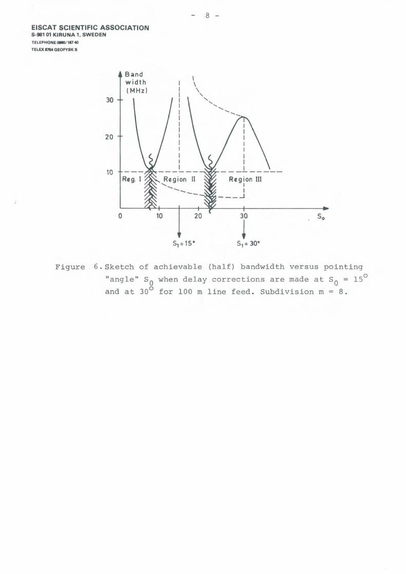
A sketch of the bandwidth performance of the particular system
assumed here is shown in Figure 6 .
EISCAT SCIENTIFIC ASSOCIATIONS·981 01 KIRUNA 1. SWEDENTELEPHONE 0llll0/117 40
TELEX 17'54 OEOFYSK S
Bandwidth!t'-1Hz)
30
20
10
8 -
\\\
-,"-"" <, .............
IIIIIIII---------
R~gion IIIII
--_-I
O 10 20
Figure 6 . Sketch of achievable (half) bandwidth versus pointing
" a ng l e " So when delay corrections are made at So = lSo
and at 30 0 for 100 m line feed . Subdivision m = 8 .

EISCAT SCIENTIFIC ASSOCIATION8-98 101 KIRUNA 1. 8WEDENTELEPHONE 0980/187 40TELEX 8754 GEOFYSK S