technical note no- 993 analytical study of …
TRANSCRIPT

lw 211945 ; -
L
I-
*
TECHNICAL NOTE
No- 993
ANALYTICAL STUDY OF T~NSMISSIO$ OF LOAD FEOK SKIN
TO STIFFENERS AND RINGS OF PRESSURIZED CABIN STRUCTURE
*By Theodore HsuehrHuang Plan lJassaqhusetksmInstitute of Techndlony

“1. . RESTRIOTED
NATIONAL ADVISORY COMMITTEE FOR AERONAUTICS
-" TECHNICAL NOTE NO, 993
ANALYTWAL STUDY OF TRANSMISSION OF LOAD FROM SKIN : , :
TO STIFFENERS AND RINQS.OF PRESSURIZED CABIN STRUdTURE*
By Theodore Hsueh-Huang Plan , : .,.-. - ‘. . . - . ..:., SUKMARY : . *. -. . .
The general problem of this paper is the defermation' e ' and .the etrees analysis ofaa pressurized .sabia. at:ruqtqre, caasieting of sheet metal skin, longitudinal etringera, and ; a finite number of rings which are equally-spaoed between two end bulkheads. The minimum potential energy method IS. used. The deformations are calculated by solving the eimul- teneous difference equations, involving three deformation parameters - radial expan.sion of rings, quilting of stringera, and transverse elongation of skin. The tensile- atre.e.e,es of. the rings and the, stringers, and the 1ongitudinal.an.d~ the :... . oircumferential stresses of the ekin are determined from: th9,: dsformatione. A few special oases from the general problem.. , are also oonsidered.' *:- he. ** .z -:
The results'obtalned during tests of pressurized cabin struotures by :both the Lookheed Aircraft Corporation, and. the Consolidated-Vultee dircraft Corporation yield reasonable ; : oheoks with the results from the theoretical analysir.
INTRODUCTION .
The requirements of comfort during a high altitude bombing mission, and in the nommsrcial passenger airplane, call for a new design trend' of airplane structure,. the pea- * surized cabin structure. 7:' . .I . .
*TPbeeis submitted in partial fuLfi3lmeat of the' require-
i ments for the degree of Master of Scfenoe from ~asaachusetts Institute of Technology, 1944,
RESTRLCTBD

2 m:... . NACA TN No. 993
A series of ~aboraZ~~fy'ihvsat.~gatlgne (reference 1) were carried out at iVright F,iel,d,during 1935 and 1936, on pressure cabins, the results of which formed the basis of the specifications of the first practi.c,al substratosphere airplane, the Air Corps Model, (Lockheed) XC-35, The resulta show also that the simplest and lightest type of structure is a round cylindrical va.ss.e.1 with hemi,spherical ,heads, and that the present standard design of eemimonocoque construc- tion of fuselage'. is: quite: +.u$.table. The first passenger airplane with pressurized cabin, the Boeing 307-B "Strat'o- liner" ( re erenfztd :2),[ .ijs-o.f,8,t&.e same .tvpe of all-metal f structure as the Lockheed, circular in section, with alumi- num-alloy rings, partition bulkheads, longitudinal stiff- eners, and smooth skin alclad covering. Following the same design trend, Boeing B-29 ttSuperfortressn also has a fuse- lage of circular section for holding pressure.
:'.i .i .t rJp,J.': 5 ; .,.‘ i - ., . . -* ":,,.“r .,s. ,..-. 9 'F ': 'T&WYi$'sroO 'pressurized cabin. s~tru-c&r~~s. 'were.. ..&,$.$(e~d. Out
'in', t~h':e'~%u&%s"s-Wright Corp.oration, .St.,, L.ou.is. Air&n+. ?<yl- s~,&ti:"(%dferencb 3),, the Lockheed Aircr,a;ft, 'dorpcrati;o$: ;(,&ef-
I ,eis.$ceh' a' and S)., and the Consolidated-Vultee Aircre,,i?& C_or- ,gxir’a-t i'on (ireference 6 ) . The effecta. of: the internal p,rse,q.-
. 4
-.,~-~,,,eu:r~e' on Ol& stresses and the strain of .the structu.re-*w-ql;,e, J . I. 9~ ~:s'pe&ially inte'stigated in the Lockheed and the .~onsald+a&,e.d-
.~uit'e,Ei;'~A~~~c~aft Corpo%ations. The results of s.o,~+e gvti..cu?.ar test' s$'ctifo'li's were represented by some plots.
""formu'las Wer.4 developed.' However, .,Some.~.~pi&cal
there were no. anal&;i.qal ',.s'ol~f:i.o?;,al':fQr the general problem of the pressurised cabin
structure. , ;'.I*: ' .: , i: 1 .J ,. .,. ~6~i!nvestigatforis .in this paper we,re*made to obtain
"'more g&?Q$&lized mathematical analyseg.oP,;Iponocoque'a~r.uc~ ture sub$ddted:to internal~*press,uqe,i,It:.ia also as.sumed that*the"$ri'nciple of superpoeit49n..pap..be applied, so that the stress analysis of a structure with combined internal pressure and external load can be made without excessive complication. I
The author wishes to take this opportunity to express his appreciation to Prof. J. S. Newell for his valuable sug- gestions and helpful encouragement during the preparation Of
"this thesis,' and also to express his gratitude to the:&@gk- heed Aircraft Corporation and the Consolidated-VultFf:t&ir-
. craft Oorporation for their interest in this work, ana their kind cooperation in supplying the test data. --,.i.,'.
'+

NACA TN No. 993 3
NOTATIONS q :, ? -. ’ -. -. . . . , . -me ; _ E t modulus of elasticity *
,' 1 " -- _ P Poisson's ratio
I G P cabin internal presstire.. :. ;. ..
2 longitudinal spacing. of.* rings
S number of stringers along,circumference of.fuselage
r
A'
I'
radius of fuselage : :...-< . .-
cross-sectional area Of ring .
section moment of inertia of ring
A cross-sectional area of stiffener
i I section mcment of inertia of stiffener
t thickness of skin l
m total number of spaces between two heavy rings
=X longitudinal stress ,, c :fi .; .L r- c .--.
circumfgrentiaf stress of skin -- - I. .- !'
=z
EX longitudinal strain
EZ circumferential strain of skin
x, ys 3 rectangular coordinates, longitudinal, tangential 2nd radial, respectively
Y radial displacement of either stiffeners or skin
n
un
wn
vn
an integer between?0. and n : *-. r ,Y.' _ ': . . .
radial displac&ment of the nth ring . . : ,( .
radial displacement‘of'skin ior stiffeners) with respect to.ring
longitudinal displacement between the nth spacing

NACA TN No. 993
M bending moment . .
a nondimensional paramet'er (l/l - pa)
B nondimensional parameter, ratio between:,ring and skin area (Al/tt) . .'
P nondimensidnal parameter (t/t) *: 5, . . .
0 nondimensional parameter (r/t)
a nond&mens+onal parameter (BnsI/t) . \cI nondimensional parameter, ratio between stringer and skin
area, (sA/2nrt) :
u nondimensional parameter (p/E) .
z operator for solving differential equation . . . .
h park.meter in the solution of differen't'ial equation
K parameter defined by equation (S5)
. 'I. STATEMENT OF PROBLEM
The simplest type of pressurized cabin structure is a. oylindrical shell with hemispherical heads, as shown in fig- ure 1. This fuselage is divided longitudinally into many, similar sections, each one cf which consists primarily Of: )A.. . . . .
1. Sheet-metal covertng y the skin _. ., . .I -. * _I*' : . . .
. '. ~,~~2~,~ongitudinal~sti~fenipg members - the stringers . . . 8. ..,a , .. , i , : :. _ ' ' '. 3. Transverse stiffen;ng"elem8nti
',' - ,; . 7 ;. , . -,the lighter forming
-, . .,rings, and the.*heavy partition bulkheads ; -, . - .r . .: . " ., 'P .> i-. ,,, The present problem is limited to the stress analysis
of this kind of structure.when subjected,to.internal pres- sure only. The analy,sis involves the determination of the deformations an8 ebresties'bf the skin,,the stringer, and &he rings. .

In the case of a mogo5oqu-s fuselage the skin stresses are given by the tw6.. e~~~tiso~s’ .‘I’ - ’ -. .: 1 ‘I ) “.
and . ,' ,“ti = rpj+t:. f (1)
QC = rpft (21
where . : -
aL longitudinal stress, pounds p.er square Iinch : . - __ . . . .I 1: .I'
=C circumferential stressi.pounds.per square inch P . . *;I .*-* * .: ~ . ..,'I 3 %a'.- . .
radius ofdfuselage;3nches .I -
r ., : dig - c X-i, -:I , ;
pressure diiier&ce between the inside $nd the outside ,.'f P - of the fuselage, pounds per square inoh
1 : ?: 1 , '5 .-, ', rf 9. 'I. * \ L ;':,I.?:. ..i: '. I: 2, . -.. t skin thickness, inches !:~.?.~~;t'i*: : am ,e- ,q . . .,L .: :
It might be a$aamed that..+f :the.longdtudtnal stringers and the circumferential ririgs'were added to the monocoque shell they would tgke as much str,ess,aspthe skin. T-his
would mean that the'average~%on~itudinal kid dircumfereniial stresses would be given by
rap uL(aV) = gA+ 2rrrt
‘. ,, iy .:
and
A' frame area

6 Nh,CA TN No. 993
By. aonsidering. ‘t.b~.;fba~,:~~~Tthi’a’; &ciq has*.etresees in two directions, that is, by considering the effeat of POiseOn'S ratio, there is actually :PObRb-a:;bif~#renae between the stress of the stringer and the longitudinal stress of the skin, or between that of the frame and the airaumferential stress Of I the skin; Two formulas-were suggest.ed l bg::.$heW artiale just mentioned (referenae 4) for aalaulat%ng the stresses of the stringer and of the frame.
.: .: - !I ’ 2 5 ustringer = uL(a.v) - k.;“o(av3 ‘. (6) ”
of rame D’“a(av) ” p uL(av)
where
P Polaaon’s ratio
(6)
A series of tests on pressurised’cabin structure were _ run in Lockheed Aircraft Corporation. The results of the tests are represented as the plots in figures’2 and 3. The measured stringer stress is checked almost exactly by using equ.atlon (5), while the measured frame stress’18 lower than the. oalculated value by using equation (6): This shows that the &in deflects more uiroumferentially thah does the frame. . . . * :-
The akfn stresses oan be calculated,from equilibrium oondltfons, that is, by the equations . ..I
, 2nr t _ gx =:, ,!A Ostringer =
a- Rr. p
. _I._ I .‘1 . t.2 ui p; &,i: Of rame f rtp....: .,
where ‘. .-a ..: ._... , .
QX longitudinal skin s’T?ess :. ’ r.V.P~,r’
%I oiroumferential skin strese ; . . . . . ,- ~ . The discussion which” fbl!Lows Ys based on the aaeumption
that there is a certain amount of quilting between skin, stringer, and th’e frame. Some generalized formulas for oal- aulating the defleations and stresses have been developed, These are all dependent o%+:a::.1&.Pge$‘: number bf.:V&Ma.b4’es’,’ such as. skin thickness, stringer area, stringer etlffnesa, stringer s$&cf%g’i7 ,f$‘&lW: tire%; f f.‘PaWW aapS&tag\i bad’. diama te r of fuselage. . . . : ,, ., ;, ., h -. .

NACA TN No. 993 7
MATHEMATICAL ANALYSIS OF PRRSSURIZRD CABIN STRUCTURD
. .' -.: L . . Method :.of Appzoach‘ * ( ;. *! *..' :- ';z :. ,
-, -,.* . . -. . ,f 8, -j : . ., -' .- -, - :. ; -, . : ,: .., . : -*he': an$kiCx of T;h~".~res&ni'pro~~~rn -is baaed.on.thb
strainrsCer&y:method, or 'in bther words, the prfnaiple that the potential energy of a loaded elastic atruature is mini- mum whefi egbilibrium is reached;" In-,Bpplying this principle, the ,f6bllbbihg procedure is followed. _
. . The first step is to make a deformation~assumption,
that-i9;:'to write a formula giving the deflection of haah part of the struature as a funation of certain qariables which are often called the deformation parameters.
\-.. i-., : .-. -' :,.. . The second step is to write the expression
-- of the- po- - '
tential energy of the structure as a funation of the defor- matios’:p&r.&m~*ers.” e ~.‘.~;‘:!,‘L .-_ 2 - . I-- .fC: 2. . : I. ; . :
B 'The, third-.step:is!to determine the change; in. pot'ential eneygy.:dve $o.~:a.~vi~$ual displaoement, that ds, $0 dif$'eypgyY,..,: tiate{the.exgreseion for potential energy of the etructu.r+:; rL,~ wl~.lt,‘r,e~p,~i~t-.to-l&ah deformation parameter. :. i, r . .:f?. 'J, j ,F x.. 5; 7, .,.
0 ,+ 3 ! -' " i, 3; : . I 'i - r,r, ::‘ 1. i-.. e L::The .f?urth'step is to determine the work dane-Rg.:ti!e,.,-'r.l~
external lpad,during each virtual d$splacement. . I ~.-~2J:: :z.-,>T .a& : . . L . . a. -: " i ; : I ,. 2 .; *. c.: .> ?.
The fifth step is to write the equations of v$r%&% work by equating the internal and the external work det'eri' ",' ;;~&g~E?,~~,, _ the previous steps and to solve for the deforma-
. <.I "3 ff c,: ?f i' .: : :. '::l""ThB'J1&st'step is to determine the stresses of'.each part'
oft:the-',itruature based on the deformation already assumed.
- ' The type and number of deformation parameters are-flex- ible depending upon the choice of the analyst.. The solution becomes more accurate as the number and suitability Of the parameters inurease. However, the amount of oomputation in- creases rapidly as more parameters are added, and therefore it is desirable to place reliance on suitability rather than
Y number. Thus the method pays a premium for good judgment.
c Assumptions .,*.
Thea.present 'analysis applies to a monoaoque struatu.ie having the following oharacteristlas:

. . 8 NACA TN No, 993
i: : 1. Circular *orbis’ section wi’thout taper
2. Very thin skin taking no bending loads
3. Uniformly di,stri,buted .stringers !apace$ gloeely enough that the quilting of the.akjn;panele be- tween them is very small and ,c.an be negleated
-0, 1;: 4. Equally spaoed light rings between bulkheads, ..the
bulkheads being aonsidered as rings of infinite rigidity ,I - , I,. . _, .
5. Radius of fuselage very large In ,c.ompsrieon with the qise of the ring I . ’ .
6. Same material for skin, stringers, and rings , :
‘. , .>‘_ Deformation Assumption - Three Defbrmatlon Parameters
1. Xxpansion of ring.-- Consider a certain 6eatiowQf a . , pressurieed cabin structure between two main frames br’bulk- heads. Between these two end .rigld rings there are (tiil> equally spaced light rings, each of which is attached to the Skin and is supposed to expand radially with the skin due to . the air pressure. The radial expansion of the ring, 61', is oonsidered to be the first deformation parameter, and i8 represented by un. The subscript n indicates the order of ring from the end,
‘: .; .I’ . . .,I. : ‘;, . a: i : .
2. Longitudinal expansion of stringBr.s’Sd9”~.~i.~l b’i’tl’keen two rinne.- The increase of the distancF,,P I+,“, b,etwqen two rings due to pressure Is oonsidered to. bqi,‘.$d.e.. seoond deborma-
. tion parameter, and is represented by vn. The subscript n indioates the order .of the span, the nth span being that be- tween the (n-11th an:+.. phe nth ring.
, . . : :‘,. _ .
: 3? Quilting of’;tringef or skin between the rings’: 3 The ‘.,s$Inp&bat function for representfng the defleoti’on of th.6:
stringer is a trigonometr!!a function, thitt is, the sine,, Purictlon, the cosine function, or a Combin&tion of*tfiese
‘ftintitiotis. In the praatfoal aonstruotion, the stringers are usually continuous through several spans, and are fixed to the rings rigidly eithkr ‘by riveting or welding. It 18, thus, a proper assump$,ion that the. rings remain untWiSted
-tikie‘d . the pre&&re’ i$:?ppI,i.tid, and..that,, the slope. of the : 2

i NACA TN No;*.993 . . * 9
defleation curve of the stringer with.reapeat to the;.refer- enae line is zero at the junotion point to the ring.
. The defleatfon curve of the stringer can be represented by the following trigonom8%i;‘ia:funat%on, which satisfies the above-mentioned end conditions, as its first derivative be- comes %ero at the ends of the span.
un - up-l Yn = up-l + (
1 - COB 2
y+w 1 1 ( . n
- 00s zy )
*-. “(7) . . . . . . . .
Here wn is ihe t@irh"deformation parameter, indiaat- ing the average quilting of the stringer between the rings.
! .; .::,,. . . _..- . . - The definitions bf'the deformation parameter izn 'b;
illustrated more clearly by figure 4. . . . .L
Strain Energy of Bending of Stringers '! ‘J
The general expresst,on for the strain energy of bending . * ' .I8 given by the equation. (reference 7) :
day % - UC-1 + WX ina 2nx --= - -- 008 dx2 2 t2
- + Wn - 00s - : 2 ta t
SubstitutSng in'equation'(8) gives ." '. -
-0 . . ..- ~ _
: a’ ., _ . :::!1:5’: -_ ._. . :. -. -.... - a.’ ,*.. ..,. . ., ,. . . --&~~!~?~‘f:.’ : - “.‘. - - -
+ 2 Wn (Un - Un,,) COB nf 00s 2rrx t
+ 16 wna aos a isrx ix . .
t . 1, - * I ‘.

NACA TN No. 993 . .' I , '2 ,
This equation applies to only one stringer at a particular iap,ctlon. The total ?,nerg$ .of bending of stringers between the two rigid ring8 ri's i3?p+SSSed ae
where e - . . ', . . : . . . . : ,. . :. r, - ., . e, . . . ._ . . _ .
ti number'of striniers arodnd cirh'umfercnce _ 8 ‘* :- I. ; i ; ; y .. . . ; ,. * ; ._
m number of spans between'two r'ig'id r-i&8
Strain JJnergy,:Qf I!lJ.?ng?i5i+oq qf,.p,f+r$.ni?rs.: ,i tf ..- : I.
The general expression for the strain energy df ilonga- tion is given by the equation (reference 7)

NACA'TN No.. 9936. .-:' 11 ::r
where I., '_. - ,.! ,z::- ,' I
A cross-sectiopal area of the bar I
8 increase in length within a.'&piain section of lengih 1
The elongation of the stringer between two rings is equal to the difference between the length of the deflection curve and the original length of the chord multiplied by a ;. .. factor representing the increase in distancy between two rings. As shown in figure 4 the elongation -1s 1, . . . - . : . . . . . ::..: " : '-2 ::
t
is= t+ I: s -cd8 - dx)](l + $): z 0
(12) , I -1:’ .
The difference betw$en<.thg-length of an elem.ent d8 Of the curve and the COrreSpqnding elem,ent 'dx of,the chord 18 equal to
da - dx = dx ]q - dx c+(E)" dx
.- 5 *v- Substituting.5n*eqiipti:on (12)'giv'ksl ., ,-m -* . - -
-. t f .a. ;,.y .,f\ . . ’ - :.-. ti.2 :’ ‘ ‘ .; . 2 ,’ .- : ! , * - lr 7’ -. ,-. -: -
From equation (7)
and
;." . . . . rr.;,.:<.t' I .-*a -:f:, .' !.. - .-=- ; .a_ - -,: ;-2Tr ( : :. . , .- _. L
7 Un - Un-i 1 lTx wn'shn E sdn
2nx'.,, . . ..l . t

12 NACA.TN No.,D9$
St can be shown that
and . . .,'
,' j!
Hence,
.* ,
and
t SC, dy a ix TT'
=zi un - %-l-l
a dx i. 2
0 ,
:.
By comparing the magnitude oC the ttio.terms of the preceding _ . I ‘. : ‘..., a equation it is obvious’ that W, or un a
is of t
very small order of vnv and it is sufficiently accurate to assume :J
,' 8 = Vn (13)
Thus the expression for strain energy becomes
V AE a = -- pn . .A. I: . : 1. ‘. . . .- ,
22
The total energy of elongation of stringers between the two rigid rings i’s expreesed as

NABA TN No. 993
- m <. v shE
=: i:, Vn
a
:: . : .. Str.9i.n Energy of Expansion of Skin
r
13.
(15)
The general expression for the strain energy for a three-dimensfonal stress distribution is given by the equa- tion (reference 8) 1
(16)
where Q, E, 7, and Y are the normal and shearing stresti'.' and normal and shearing strain.
* . . 19. the present case, the problem of expansion of skin can be're-duded to a two-dimensional one, by assuming-that the x- and z-direations coincide, respectively, with the transverse and tangential directions along the skin, and that the thdckness t of-skin is so small that the varia- tion of it can be'ni$gleioted. Having the assumption-that the:' skin is expanding tiBifohmlj+;'and symmetrically along the cfrl.’ cumference, it can be concluded also that the membrane shear- ing stresses TXZ vanish. .The express&on for the strain energy is thus reduced to th.e ‘fo&loving simplified form
where r is the radius of the fuselage. : * ,." . . . 'In the ca8e of plane strese distribution the r8latiOn
between stress and strain is given by the equation8 (refer- 0 en08 S): I

14 NACA TN No, 993
,cx = $ bx - P Qz)
(18)
Es3 = jj 1 be - k Qx) *.I : .I -: . . p: , : : . '... . ' . .
where .,,I.k .,i:?. Pois~~~,fi,~ s ratio, Solving for Ux and Qz gives .: . . ; . : :. '
- . em.
I :' (19)
a, = E, + P EX E .
1 " Pa
Substituting in equation (17) give8
! v A’
2 Xl (%I a + 2cb cxcy S ~z~),dxdz (20)
The strain E.x "Can be a88umed~co~etant'throughout the epan . through the same argu'kent ti,s‘in ,the g~,?iti'ous seation. '. Thus :...
:. ,I r . '.. , Vn ,. 'gx = - (21)
2
.The etrain E& can beJexpre8sed in term8 of the other two deformation parameters.
Y ‘z = ; *.
Substituting equations (21) and (22) in (201, and'int&rating p by noticing the fact that

NACA TN ;:No: 993 :. 15.:
1 &... i .-- nnx - CO8
-'~&.y,, .:,: - 5--.
-dx=o t t
..* : * I . . f -, ! and
t . . . .
s cosa ydx ' =-
2 0 ,, , . . c.. . . _- a . - : -< i.:.- * I. . ' - .t ..;;.
- . . lead8 to
.I .
. v =- + 2P vn u,,p + ’ Un-l 4
The total energy of expapsiQn.of s&$n between the two rigid rings is expressed a8 ;:. ,
+2 3 8 Una + -Wna + Un Wp 2 . + .-yn-l. .Yn )I , ,. (24)

16 NACA Tlf'No; 9'93.
Strain E)nergy of Expansion Of Rings
born the general e "p
r.easion for the strain energy of elongation (equation (11 ) it okn be stiiciwn that for the ex- pansion of ring
v 0 A’PJ * :.
.(2n (r +,u,) 7 2nrja 2 % 27Tr . , -
where A' is the cross-sectional area of the ring Or
v:sO nAtE a . . - Un r (26)
The total energy of expansion of rings between two rigid ring8 is expressed a8 , -.I
Strain Energy of Bending of Ring
$!he general expression for the strain eb,e,r&y .o$.bending - ; .i., fe"gyven in term8 of the bending moment by the equation (ref- erence 7) 1, ,; .‘- : ., v’ =’
s Made. ..* .: ,-. t . ..I. 21I :..,;c; -.
i - . . .., L
I - .;.- s ,
The bending moment for beams having clr!bular c.entka*l' axes is expressed by the equation (reference 9)
.- . . 8 .!L- 1 EI Fa
Y+ day’ p dGla >
(28) I
where .I i
r radius of curvature
Y radial expansion of ring
$1 angle representing position of section

NAOA TN No. 968"' 17
For a uniformly~Bf~bnded ring,'the deflection.-y* la constant all around the circumference: that is. its second derivative
'vdnishes. Thus - . - .' -a : .- . :
s
2Tlr EIy.
v=;r ds 2r- o
rr31-- = , =- r3 y- (29) .
In practical cases, the depth df the ring is usually very small, while the radius r of the fuselage is very large. It can be 8hOWn in the actual example under the section Analytical Solutions Applied to Actual Test Seotiona that T the value of A * - *. . : .
"A/r. r3
is very small in oomparison with the value
of It is thus allowable to neglect the strain energy - of bending of ring in the present di8ou88iOn.
Expression for Total strain Energy
The total ,stkain energy between the two rigid frames is expressed in term8 of the deformation parameter8 a8 fOllOws:
m v = G, -,unwl) a +
1
m L. m "; . . . . . =tTna-+ 2w
.U vn
,pZ.+hpc c (..
'* 2 :-. + wn
1 1 m
+ L.-s ( 3 rL-l 8 -%-l ~++Un-; un+;una+;wna+un wn+"n-i wn )I 1
m WA’1 +- 7 un
a ' ; r L 0
. . (30)

18 NACA -TN NQ. ..998 . . . .:
Introduction of Nondimensional Parsme-tere . ..-. - : '1. i ., , :. :
In order to $imp.livfy the foim of the 'gen?r&..equ+t:i'q?%, - the following nondimensidnal parameters are’ introduced: .
1 a=- 1-p
631) I
(32)
f-t . . a
(33)
(34) i
95) __ . .
.(36) . .
- I
Change in Strain Energy Due to Small Deformation 'l' - 1. >,> z
The effects of the small changes of the deformation on

QACA. .TN 3'0. '9.93 19
the change in the strain energy are determined by differenti- ating equation (37) separately with reepe.6t to the deforma-
tion parameters. Since the derivatives of c (un - Un-l Ia ?3
. l
with respect to u, vanish, it follows $hat .
bQ - dun = 2nrE %l
vnt vn+l) + 1 26
(38)
t.. . .
= dv bvn n
= 8nrE[p%r, + pa{8in+ #b cn'cun f wn)} ]dv, (39)
w ) * _- . . . \'j ,- . . j*f . .
= dw n= 2rrrE (40) - awn
Work Done by External Load : . .
hhe work done dlio to thzo - _
the end 6, i.cterkA pressure applieA to
",-he cylindrical stract+,ura nay be expressed aggrox- +mately ~JY .- -
, m .u = nra p
c vn (41) . . =. -.-I
1 .
where p 29 *hq pressure difference bot~veen the inside and the outsido of ,i;he ccbIq.
,, ' . . The Tr,rk d~ue 2.~10 to the,internal pregsure applied radi-
ally is expreseed'as".' . . .
'F. . . .: .' . . ' . ' .": -_ -* ._ . . . . ;'; . . ' c ;- _. : - 7 . . . . _ . *-. i .., . .; -7 * - .- I . ^ _ : ---' -_ . . . , : - 1.. ; :

20 ' NACA TN No. 993
+Wn .
m-1 m - 2nr p 2' C’ un .+
u. + um +. .,.. I 2 .+ ., , WZ' . . '.
5: J : (42)
The work done by the external load during the additional . variation may be expreas.ed similarly by differentiati*6ti.
I
au - d u, aun
= 2nr p t d un "
(43)
(Except for u. and Um, which are taken to be zero in this ease)
=dv n = nr = avn
P d vn
=dw awn
n = 2nr p 2 d wn
General ZquRtione.far Determining
the Deformation Parameter9
(44)
(45)
Equating the change in strain energy to the work done by the external load during each additional variation re- sults in .
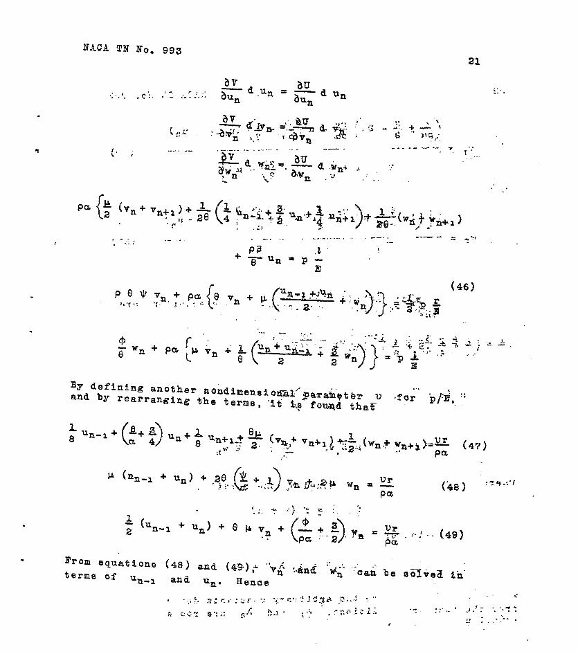
NACA TN No. 993
, I By defining another nondimeasio~~:.'~mainetBr . . . and by rearranging the terms, '56 5,s f0-i thaEv. -for bjd,m ::
.
L 8 UP-1 +
(47)
(k8) :19.:‘!

22 NACA T$? No. 993
and
z[(l+~)-P]~~[~a-(1+~)] hn-l+“n) wn = (61)
2 [ (1 + 9 (.& + ;) - pa]
For soloing u,, the simultaneous difference equations are written in the following form (reference 10)
1+Z 2 u,+epxv,+ ($+gp,,.g (52)
where z is an operator defined by the relation
zn f (x) = f (x + s>
The solution of these equations Is
un = Al hln + A, han + ii (53)
where A, and Aa are the arbitrary constants determined from the boundary conditions, A, and A, are roots of the equation

HACA TN No. 9193
1.+ --I- $ 3 A'$ 8 ( > z
; ha ..& 'ci\ + h2). h + A2 . a . * .2, -12
_,. .
cr (1 + A) 20 -g + 1 A : 2&?8 ( 1
= 0 (541
i . .
and ii is- the particular- solutfon of the difference equa- tion determined by substituting E = 1 simultaneous equation (equatiqn (52)).
in the preceding
Equation (54) can be k@duced to the foi,lowing simpli- ($$pd form
_ .-'. .".- -_- ..-. -. . . .:
,' L& L. I _ : *_ -.. .F ..+.-# -1, .=
'A.. +'-g ;, + 1 ; + ' A. - J -
co,' 1',! .
'8' . . ._*I ,. .- -(55)
where
.yr,
(1;; ;; - : .
In general KS the coefficient of the X-term, is. pos f t$y.e and usually lies between 20 and 50. The solution zfc'$his'" quadratic equation will be'approximately
.: -: ,z . ,- I- :-... _- .

24 NAOA.TN No...993
The particular solution of un is.dgtgrminqd-by solr- ing the following simultaneous equations .,
c. I
( 1 l+ 1 vr F+epF+F=- a Pa
2pu+20 &L,l ( 1
Vr v+ 2piT=- a Pa
The boundary conditions in the present case are that of the ring
ana. zero. -+-, ,. .
or
. . A,h','miA,h,m+;I=O "
Solving for.!. I,. “and- ‘A, * from equ'at-f&s'- (a) and (b) gives e :1 : . . . I

MAOA TN No. 993 25
Substituting in equation (5Z),:gives . -e, . . . . -, L :>
,I *
Rearranging and substituting h, by hs-' gives . . . .i . . 1. _ ., .
h m-11. + han a
1 + ham ) The other two deformation parameters vn and wn can
be determined in turn by substftuting the values of 'un aad
un-a in equations (50) and'l.51)
The stressee of the rings, the stringers, and the 'skid"3 can all be determined by.k.z$w$~g3he .deformations, OF in other worde, the strains of: the structure. For example, the stress in the ring can be written as. 1
;. .I . . ._ **: . -* . _ ;. . ..-r 1 .., .:: :.:. : :';'. ;, -4 1
or Qframe * ' "frams. .i- - ;:...' _ _ . . . . . .._ '
% '. . ;,
Qfralq .F, 2 .r ! l . , $61) :I;
.
Similarlyj th!e.etreas of.t&e stringer is equal to . . ,..- - .,.. -7 ,: j : .f . I . i : - -r. .- ' , - . . . .: ~-
- * 1 Q . : -%tEi*jg.e,r:e.. :F .--; .afringer I .i - . . :; - . , ', : _ : .! J,L" -, z- f-. -, .- '2. .r. .‘I- ' . . '. .::. 2: ".*
.*. . (62):'
. . . ; ,* Y
The longitudinal.bt~es$ '&'&he skin may be written as 1. -- . . - -.s.... .* 2, _ - : : - ' . -1 . ..- .

26 NACA TN No. 993
vn Y T+c1-
= rE 1 " tJ=
($3)
where y Is determined from equation (7). The circumferen- tial stress of the akin may be written as
(64)
The bending moment of a beam can be written in terms of the deflection. The differential equation of the deflection curve is
M= -El+ (66)
The second derivative of y with respect to x is
day _ un - unal na lTX 4lta 27TX dxa 2 7 cos y-+ wn -CO8 -
t= a
Substituting in equation (65) gives
M= - E I - %-I 718 co8 E+ w, ti cog 2nx 2 ta a aa > -i-
(66)
It can be se.en that the bending moment is maximum at the end of the stringer where the ring joins, At the end of the rigid ring,
Un-l = u. = 0
un =ul=r l- ( ham-l + h,
1 + Aam )

. . . N+S T,N No. 993 27'
. .
Particular Proplems . . ,".. . . . I. Pressurized Cabin with,,InhinitialK Many Equal,Spans.
f ft.-j *I * .- -- --. - -. ._. a. ..'. It i
e ~+~o$p~o_~$~‘th,tit. 'the -defOrmati& '63: cacti p.pgei 'of
the preSs.,Ti'Z8d cdbin st,ruct$re with infinite-ly many eiual spans are identica'i. In the general equations,
, , ..
These are the same equaktohs a$~'the'~imultaneous for solvin
equatiohs . -_
7 the particular solution in the previ'oua 8eCtiOn" " '
(equation 48)). The solutions are -.

28 NACA .TW N’d’. :$-93’
c It oan be seen that equation8 (50) and-i51) reduce to equa- tions (70) and (711, respectively, ‘by substituting Un-l = u, = U.
II. Single Spar! Pressurised CylLnder with End Frames of Infinite Rigldi ty.
This kind of structure will have only tpqqsyeyqe.+ad . radial expansion of skin, but no defdrmatidn of the rings. For this case the deformation pa’rameter u in equation (58) Is zero, and hence the first equation in (58) vanishes. The problem is thus peduoed to the solution of the following equation
(72)
The ,s:o+W%fons are ’ . . . . _
, \ , f ;-.’

--(73)
: . - -..j.” . .
‘, J75) . . . . _

30 NACA TN No. 993
1. Leakage rate
2. Deflection due to internal pressure
3. Stresses due to int-ernal pressure
4. Bending test
6. Torsion test
6. Floor-eupport test
7. General instability
8. Frame test
Since, in the present problem, only the effects of pres- sure are of interest, a summary of the test of the primary struoture is given.
Desoription of test- setup.-, The general arrangement as well a8 the dimension8 of the test apFaratu5 are shown in figures Sa and 5b. The essential elements of this equipment consist of the following:
1. A full-scale aeotion of the fuselage
2. A l’arge reinforced concrete block which serves as a fixed end to support the teat section
3. A rigid steel framework or loading head which was attached to the free end of the test section
The test seotion was circular in cross seotion and was tapered with a ratio of approkimately 1:lO In the longitudi- nal direction, The primary structure was composed Of a 245-T alclad framework of channel-section rings and bent-up, J-section stringers to whiah a skin of 24S-T alolad sheet was attached. The stringers were uniformly spaoed at 6’ inter- vals around the periphery of the cylinder, except at the bottom, In which case 2.5’ spacing was employed. The stringers were of five different seotions, only one of which, the LS-160, made of 0.032-inch 24S-T alclad sheet, was used mostly. This section is given in detail in figure 5b. The rings were spaced at an interval of 18.4 inches, A typioal section of the ring is also shown in the same figure, Two thiokneeses of skin were used, 0,032-inoh sheet on the top and the bottom, and 0.040-inch sheet on the two sides.

~ q-r.:.. :il'he pr'bssur~i.t&%ohf-of .th;e-ktist s;ebt\ion.~as: 8~cc0n1pli5hed .,wd.th?%he ~.ompres.sed air-:whLch ~was.ld'e& into ,the pylinder : I :' I:
thrgu~~~~;.eBfrety:.Psbv.eI~ocsted,:#ith~.~the:-con~rstBLsuppsrt- . -in& 6truct'nre.F :-. Thb,.air.-was s~~p~ded.~.onst~~t~y.' for:.baJ&nrc- - ing the leakage of air through the skin,
w 'i 1: ? ; LO : ; i: .*.a: c. .,f,;" : . : ', ..' t _. * .:- - :r< ! _ I . '2 ::Ths Bald~iP1-~~uthwarg-Zgde.';el.~htrlsal:isBraih'gageerw~ '
. used ,fbrl,me.asurfng;.the stre.sses.i -. They- ware! moullted; upon: the . . sdfaaesi bf theimambars, i'n~~w:hich:the stresses were',t.c be..;
m-e'~~~ur.ed, by csmanf~ng:~thsm to;these.surfaces... L--C'- 2 .i ':- e. ' ..I. -. . . : ) .' '., ;. '. *
Pressure defleitions . c , . ;‘ . . ,a$ + 9' P .' :i ---fL, ._ . -.-'. .---r-; .f->;
mm- .- The,.~~~.~,def.lectbDns-r'ere.:cOrn~~:.. posed of two parts, firat, the defl‘ection of the center of It&e3p&neb- re&at,ivett6.*the;* strZager%;ahd se&n&y, the-: d'?- f$bc,tLon!- of., the:.strjLngsr rela%~~.e..tp~'.th'B fxamg4 . These ..deb. flmxtiops ~.ere-~ahl!.measur~ed 'by the. d4al::ga.ges as'; eh,ovn.. in; 1 the. dia.grammat$p aketofiea:in f,igurss, 6.e.nd-7..: :The!.etrCng&..
:'and ungxp@cted resP1t:I.n tha,se figures-is that skin betyeen: the stringers:ha,d~an invard deflectdon. An-explanstPOn. for:: this nay be.;t~at,.:thege~panele-had. a.slight, curvaturg. in the' longitudinal-4irect.iop.. The-de.f1-e&ion of.. the stringer be-
. tween..the frame is outguer.d+ and is, practicaJ.ly directly :... , prop,cr,t$onal.to the internal pressureb !. .- --. 1 . _.- ;w..... ,‘Jt-
Pressure stresses.- Tke'results of the pressur'e sti'reis measu@ement-have buen discussed-previ.ously- and are rs,p,re- seat.ed,in the plots-in, figures< B.-s.@ 3. , . -
. * “ -1 - ., *>" ..'.-;'-"i 3' . ' *-. -:- . . *..* :, --,-;, '-.c.-' ;-.- j ',-.- . - r. - - . .
: ‘.)I . 1 I , . :. -. -:r * ;.:
l : . , -- - -.. . :I >“: _. - : ;:1C3.:g
. . . -- . : iv. ” . -=z 3 ,* ;-
Donso;;~ate-d-Yultee..Bircr~ft..dbrpor~~d~~ madi'a:J';L:rieP'i of tests to measure the stresses.!dn and'she deflectioasSJ&kd. the structure members of a one-haifVscale l'dosc&heei e'icl.- tion" of the D-32 fuselage under maximum operating air pressure-: We. ..t.es.t,e: qqper,ed.;two. kj.sdar'pf .apBcinlens : the Afloored speoimen,'?which was a cylindrical structure with flooring and floor bracing inside, and the "control 8pecimen,R which,w~s,g~pgFfegkPy .?yIPmetri$al:,cy;aiqder:,to:be*used.as control in preliminary testing. Only the.tests of the con- trol specimen are described here, ae this specimen is similar to the strupture .yhk_qI~ ig,,digF.ysoeFh.in..thi.s,;-pggQ~.~ -
.: L Test setup.- As shown in figure 8, the test seotion was
made with 0.016-inch skin riveted to 0.020-inoh angle

32 %ACA.TN No...993
etrih&ers:wlth: 0.032n~n&.l.ch~mdl belt-fr.ames:, '-The stfingers, 62 in-.aumbir;; were; d.$gtBibuted .un.i.formly' around th* psriphsry of'the!cylind~er:?~Th~'b:e~.t'%rame8~, T-5:ln fiumb~r~.including.* * thaw -2.' end:bulkhbad&;l: Ware. spaced at anr inte'rva~~~of:.1.0.daches.
,I '.I,) .' ,,.,; f,-~',f . :.. ..,? B",!>:,:.. 1 f ;; ' The test 8pecime.n was'.'mounted in a boxlike structure
-3 :.
:B'tebl' ,Jig. witW,the-.cehter line. of, the speslimeh .in a vertical position. The:, topr,bul,khIr'ad oft-the* Is~pecl~eru:~las,held.l'n &: fixed SIt,e'ral position ,hyr me'ahs of' bsi,l-*baaring' guide. .rol~ls~s. The effect was.that:as the' specimen expanded ,under pressur:ra~ the top bulkhead could breathe vertically but it was re- stra'i~ed',from:-lat,erLl~, motion. .' . . :.".:*I 1 :.. : ., *
I. .I -. 4' , ., .i. '._ . , . '. } ' .; - '* . . , ,: f --; . ~+S.fressea.:~. Thle s.tres:ses of, fh\ control specimen at. 6-1166
psi measured bp.the 'sG&lstraih!'. &age equipment are shown.iti. figure 9. 'The averag&.+alues of .indioated'stresses in- the.. membsr%'Bt 6.66 psi compared.slth the. stresses-obtaineb..by..:' simplb oaaculations: (eqti&tims (31, (4),::(6), and (6))*fo,llowl In the.stringer - 1300 psl;ve~sus 1366 calculated; in.the belt 'frame1 - Skli
'440.0 pii..versus 6660 calculated: longiSuddna1 'Lv.477'0 psi.:versus: tiB~0 'celcui'ated.; and circumf'.,'r.en.~.ial-
skin 's$r'es's' u llji2QO p$'i..versuW866O calculated: I'?0 e' ex- perimental value of ciroutifersntial stress was a mas,imutrzn*-'.. value instead of an average value.
I i* * ‘I . .: :, ", ', + . 8 ,.. l.. r - . . . I - a-*De~fdoct.ions.- Btarrstt defleet5oh gages reading 19
l/lOOG:h were used&o: tieaaure"'th&? d:e$lection of the,. mem- bers of the specimens under pressure. The belt frames did not deflect, e.vc"nl,y a*lpng th,e pe_r.iphery, but the average de- flection of,the cent& b< frame'&? .the con’ttibl. specimen was 0.018,iqch .at 6.66 psi,. The radial def.lectiona of skin and stringers'tiith respe+t to end 'bulkkead$-'a& 6.66 psi were shown in figure 10. The quilting of the skin and stringers was,from 0.006 to 0.020 inch greater than**the,b.elt-frame de- flection! :I,$ no &s'&'ivhs a fla't't&ing'.bf the" skin be'tween gtr~ng&r~“&fm~icbd ,lh this are&$f.'t~';' * '?.'?"',I s. : . .- 3 * t 'Lb
. '. ,, e. : .: .<.:..A-. r . ..I< - . . ) :*:: _.. ,,, . . L. , ,. . . I , -+i{j 1 . . . ', ',. 7 -..' : 'II ,.,;.. : .- . . .. (1 ,. 4 j
ANADYTIOAL SOLUTIONS APPIKFXD‘ TO 'AGTUAD TEST *SECTIONS :y,' ',. *I:t'.,,' 2 ,c, ';.:o;.:'j-l ".l, ._ * ,:-. .! ..-;7. . : '1 '1
,. . . +. '. 'I , :- . . . . : I.* Tssts, of'P*e~sur'ie.ed %Bb%n StructuFe'&t.Lockheed' e *
Ai,rc%aft Corporation'; ' I' .:. I r " t rri. ,. ! ; " '"...j . b---c-: I: .j I..; * . . ‘IT,- . .*, -1 .- . , [::*;.
For simplicit$~~in &nalysi*; the fbllotiing assumptiohs" are made:
.'. "*' , 1.. .i- .;:!I ; ..i,.-.- - _,. . . _ :. . '. ! :: . ,- , * . . ~ '; 1 ' ." .. ; r 8( .*. ;:..... .'t ,...' '- . . . I 3 '.,, I * .' s
.
d

NACA TN No. 993 33
1. Same type of stringers (LS-160-0.032)
2. Same type of rings , 3. Same skin thickness (0.032 in.-) around periphery
4. Same stringer spacing (Sc) -
6. I?niform fuselage cross seotivn
The pressure difference is assumed to be 6 psi throughout the entire.computations. The fmportant dimenslohs and fig- ures are shown in the following list\ '
P = 5 psi
E = 10,300,000 psi
CL = 0.3
1 = 18.4 in.
t = 0.032 in.
r - 65 in.
s = 72
m = 10
A = 0.0617 sq in.
I = 0.0096 in.4
A' = 0.238 sq in,
I' = 0.317 in.4 .
The following nondimensional parametera are derived:
Ii = P/E = 5/10,300,000 = 0.485 x lo--6
4J = 4n3 s1/t4 = 4773 x 72 X (0,0p?6)/(le.4)4 .- = 0.748 X 1O-3
P = t/r = 0.032/65 = 0.493 x 1o-3

34 NACA TN No. 993
B = A'/tE = 0.2~6$'(0.032) (18.4) = 0.405.
8 = r/t 3 65/18.4 = 3.63
a = 1+1+. - l/O.91 = 1.1
JI = sA/2nrt = (72) (0.0617)/21~(65) ([email protected] 0.34
IFor further computation the following vaQ.ues are also calculated: .
‘.’ ., . . , : . .
+/pcl :’ = 0.74&x 1O-3/O.493 x 1O-.3 x l,.Lk, 1.38 .
@ha -I- 3/2 = 2.88
+/Pa - l/2 = 0.88
*/Pa + l/2 = 1.88
*la = 0.34/1.1 = 0.309
1+$/a f 1.309
B/a = 0,406/1.1 = 0.368
@/CC+ 3/4 = 1.118
B/a-1/4 = 0.118
l- B/a = 0.632
P/a+1 = 1.368
p = (0.3)" = 0.09
vr - = (0.485 X 10"') (66)/(0.493 x 10-j) (1.1) ,g'Oj&; f= I.
Thk'value of K in equation (65)‘ii *- . .
g= (2.88) [(2> (L3.09) (1.118)- 0.09]-1:309- (2)(0.09') (0.118)
(0.6) (0.88)'[(0.6) (1.309) - 0.091 . (0.25j (b:Os):' -
= 30.4

The value of As fin:,equation...~~O.):.fB.:app~,oxl.mat?lY equal to -l/K or
. A, = - l/30.4 = - 0. 032ie- ,‘, L: 1; . .
5 \ It can be seen from equation (60) that, the expansions of the frames are nearly identdca'i:i* ,hd,,thai'~his.-problem can be reduced to that of pressurized cabin wit% infinitely many spans. that
By using squations (69), .j7O.),>and (71). it is found : . . ;-. ;; .
(0.0681) (1.309 - 0.16) (1.88)
u'c (b.09)(0.632)+ (2.8~)[(i.3~8)~1.,3'OS) - 0,03] - 1.309 .
. . = 0.1265 -": ' :
3.648 - ’
= 0.0347 in.' ' ' *+.- : . . . z : .-..: _
(0.0581) [t;.88)(1*;68+- ;O.k) 'i';3) (0.632)/ 0.51 . . v= .-
(3.53) (3.648,) . *’ : 1 . - ^ . . - :. .
= 0.00361 in. , L
. .
(0.0581) (0.368) (1.309 - 0.15) w=
(3.648) .
= 0.00683 in.
A comparison between the strai'h energy of expansion and of bending of ring is shown.
= wx (0.238) E : ? :
65 (0.0347P
= 1.38 X 10” 3

36 :.I NACA TN No. 99.3
Ehergy of bending (,equation (29)) 1
V= 7133) I' r3 u
L “b 1.26 X 10” m ’
It IS obvious that the'energy,*of bending of ring can b.e neg- lected. ..I ., 1
The strains and stresses of the structure are derived, from the values of deformation parameter.
Longitudinal Strain of Skin (Strain of Stringer) ._ II ';.,,
* EX = v/n = 0.00361~18.4 = 0.000196
Circumferedtial Strain cf Skin. iav.) . 8 . I . .
u+w 0.0415 "Y" r = 65 = 0.000639
Strain of Frame
U 0.0347 'frame = F = -b5- 3 b'.OOG634
Longitudinal Stress of Skin . -
5 0.000196 + (0.3) (0.000639) x 1o 3oo.ooo 0.91 * .
f 439;o p,si,.

. . . . L’* t’ r ,
. -%ACA TN.No, 993 37 * '.
Oircumferegtia& Stress of Qln,, .,.* , :,...;. ;:q -* . . . . . ; - . , . . - . ‘- . --
Stringer Stress
= 0.000196 X'lO,~OO;'OOb 8 . . . I .
- 2020 psi. '+. a;. ..* :c > - y. 'I-
Frame Stress ::, . .
uframe = Eframa '
. . I = q.000534 x 1~,30,0,000 . : . . = 6500 psi . * . ,-.e
The following is the comparispn between the experimental results and the calculate'd'values: - "
;. Experimental Results . r: : *.. p. ,! , . . .
: . '; @' . ::..t . . : &) '".T ILL:.-:.: [f i/i. .-';i .': _ - .. '.. . . Ofrarne;,;
=z .- = .Q,fjgO ~'~F&O~ I I \'.'. .a " ::' \,..: z
I . '. Z,". .L"- . . Qstringer
s lkoo' 'f x*r;. z -, 0.374
ux '.fW: =
. .
: . . s.-- .
Calculated ksults ' "rA'-'d . ;* \ :* I:,; - . . . 't \, , ~
. . ,:i:;T,: - Oframe = sb00' . !.' 9 ' ;l :,> .z-
02 . $gcz#) :~;l,?$?!? = f . "
u5trin'gB'r C .c3m.q [ :. ".I.":',: e
uX =m=: 0.460
- : r. . _ . -

3 * x :: NACA TN No. 963 5.. I
These results are within a rsas,onable @eck. ._ ..a.. . I
II. Tests of Oontrol Specimen at Consolidated-Vultee- .' Aircraft Corporation.
A liet of the important dimensions and figures for the control epecimtq %at Consolidated-+ltee aircraft oorporation - is given.
P = 6.66 psi
E = 10,300,000 psi
c1 - 0.3
t -'lo in;
, . . - ‘.* .-.
t s 0.016 in.
8 = 52
m =4
A = 0.026 '9q in. (see appendix)
I 5 0.00102 in.4
A' 6 0.0744 sq in.
I' = 0.0176 in.* ’
The following nondimensional parameters are .derlved:
V f p/El = 6.55/10.3 X lo6 P 0.635 x 10"
4 - h-r= Ed/a4 = 4l?3 52 (o.oClo2)/zo4
-0;659 x IO-= ' .;
P = t/r = O.O16/28.5 = 0.562 X lo-=
B = A'/0 = 0,0744/0,016 X 10 I 0.43 : . -'!.?:jl':. '
8 = r/E = 28.6/10 = 2,.85 " ;' '*,
a = 1/1-p = l/O.91 - 1.1 rr * . *

.: NAGA TN.No.. 993 .' 39
JI= sA/2nrt'= (52) (0.025)/2d28.5) (0.016)
. = 0.536 . ._ .
. . . - For further 'bomputation the foilowing values are also oalculatsd.
; v. . . . @/pa = 0.659 x 1O-3 /to.562 X lo-=) (1.1)
. = '1.07
? '. J . a. . ( . * cr. -* .- z*
@/pu + 3/2.‘,=i.ti 57 ? . .*. . - . . - . . . : -_ .I -
Q/pa - l/2’%= ‘a.57 ’ *
@/pa + l/2 = 1.57
$/a = 0.536/1.1 = 0.488
1 + $/a = 1.488 .
e/a = 0.465/1.1 = 0.423
e/a + 3/4 = 1.173
e/a - l/4 = 0.173 . ’
I:. . . . . .
1 - e/a = 0.577 C.
@/ a+ 1 =I 1:423 L:
P 0.09” pa = (0.3)= ,.
E= X 16 0.635 X 28.5/0.562 X lo-= X 1.1 Pa ,
= 0.0293
. ‘- .The vakus of K in e@+ati@8?45$) is . ._-,__ . f--. . a-_-....
K= k.57)[(2)&1:488) (1.173) -
. .
0;09]~ 1.488 - (2)(oIO9)(0.173)
(0.5)(0.57) c(0.5) (1.488) - O.q9] (0.25) (0.09)
= 44 . . L ^ /‘.I> l .:. - , ,,t:..:- . . . - *-.--w.- _. - _ . . . - . - II _ _ The value of ha,~~,4nfeq~~gidq:(~O) is approximately
equal to -l/Ii or
Aa = - l/44 = -o, 022+.” f --

40 BAOA TN No. 993
The value of J is from equation (59) '
ii= (0.0293) (1.488 - 0.15) (1.57) (0.09)(0.677) + (2.57) [(1.423)(1.488) - 0.09] - 1.488 -
r 1. = 0.0163 in.
. The expansion of the senter belt frame is
t . = (0.0163)
j.2) (..0.0227)a 1. -++ (o 0227)4 . -. .
= 0.0163 In. : .'.' .
The expansion of its adjacsVnti&ams is .-;c1 . .'
=c l- (
ha3 f h . Ul 1 + ha4 i ‘. ‘9 . . . ,.
= (0.0163) (1 + 0,,0227) .h * '0 0.0167 in. . ,,
. The parameters of longitudipsl expansion and radial
quilting of thS:.skin bstWsii'thsee'two rtngs are determined by substituting the values of u1 and ua in equations (50) and (51) ,. .*
(2.57 - 0.6)(O.OS93j -' (0~3)'(1.57)(0~016j"t;"0,'0163) va =
- , ,' , :. ,' ,. . . . . ..- -.: (2). @85$~:1:(i,q3.8) 42:57) Yra,lbsJ:~' _a -I 5 . ~o.,~.;,~o~gg*i~,~ ,'.:,;: . . :,f:-:**!, :i;, C-J :':'.i. ; , I ;
.
[(2)(1.488)- 0.3](0.0293)+ (0,09-1,488)(0.0167+ 0.0163) - wa = * :'.;,";*.* , I .,, .* L ' b . - .(gs); [ (1’.4&)?(3;&) 2 (J;sgj :;--: -, .; ..
. = 0.00435 in. ,,. I., . . . .

NACA I/N No.' 993 . . 41
.
A comparison between the str'ain energy .o.f. Bxpansion'and of bending of ring ia shown.
. . .
Energy of expansion (equation C251:I'. . .
V= RAIZ~ s .r
un * . . .
= Tr.x &744 x, E x (o.ol'$B)s 28.5 . .
= 2.17 X lo-' E * .
. .
Energy of:?tknd'i&g '(equa'ti6rs 'G291.) - : *.
v= ll E I' ; , :. :.. .; ;-i-.-m - f-7 _. - .: r3 un
. . ..--..' -.._-.- :: .
:._ :. ..,^..
72.x E X 0.0176 -* =- (0.0163) - -
(28.5)" . . ;. : . . . . '
'="3.9 x 1o-8 1 .
It is obviqus that the ,energg of bending 'of ring can be neg- lected hers in the diSCuSSiOn, ..::. 5,V - .:.:--.!i ,c~~,+~, ti. . . . . .m ..-- --...- . ..-mm--.- ..v. j--_ - .
The strains and stresses are derived from the d,eftirma- .tion parameters. , . "2: -.
. EX = Q/Z = 0.00199/10 = O.O~O.l.99,
Circumfsrsntial Strain of Skin
Gl1+us)/z*ws ,. . . .L (0.0167)+ (0.0163) + o 2 . oo435
Es = A._ * r 28.5
= 0.000734

42 NACA TN No. 993
,.,Maximum Value . I . . :-. . ., .-
'a (max) = (u, + %3>/2 + 2 w2 ~ : .,I:
r
0.0167 + 0.0163 + (2) (0.00435) 2 =
28.5 ..r-
= 0.000954
Strain of Frame
Eframe = UP /r = 0.0163/28.5 = 0.000572
Longitudinal Strees of Skin
P 0.000199 + (0.3) (0.000734) x 1o 3oo ooo 0.91 9 I '
. 2.. :
= 4750 psi
Ciroumferentlal Stresses of Skin , .
, . . Average "'a ,
9-a: = 0.000734 + (0.3) (0.000199)
0.91 'J. . : x 10,,300,:000
. . .
= 9.000 psi z. ;‘! .-. . .
Maximum . . ..c -: I -. . . . .._..- - .
ua (max)" 0.000954 +'(o.i) (q.000199) x 1o 3oo ooo
o, 9i . . . . . '.c... I I
. . = 10,800 psi ::! 2 ;r: . I. _
.
.

NACA !J?N No. 99.3 43
stringer stress I 1-v * &.'a. . ,, :-. ., .' .
Ostringer = O.OOOL99:.x 10,300,OOO
- 2050 psi ' . .
Frame Stress . . , ? =
Qfrramq. . ~ = 0.000572 x 10,300,000 . + . :: : ~ -. . f:;-.::. -_ .p. .', , _. -' * ,I
= 5;49o-'psi ., . ,T :' * : ? -
Ciro~mferential ‘e*& 1’ ** 1. I :. stress (av.) ----------
Circumferenfiii &kin ' -..z, .,. stress (max.) . .- 8 : : ll,.ZOO
* ..,. . Stringer stress ,, 1,300. ;
Frame et'ress -0 *, . .:
4,406' - . . - ,_. '. -. T .* . . I -*
*. . 2.. -9 .'- . .-- .z
The., exp.b~.i~~~oP' $.ib'penter'-.i be 0.0163. ilich ag,'$&p,B:f,e&*with tl: inoh +.'S., :,..' 'L; .,.- rC'Oit' 1 ,:

‘44 ,,FAqA,TJJfNo. .293
DISCUSSION OF RESULTS AND SUGGESTIONS .;f,,.lz,'.c
. T'OR.hlURTHER DEVsLWMENT > f v, .I . . .-,- em,
R’rom the comparisons beiween the- experimental results and the mathematical solutions, the following facts can be noticed:
.:a . 1. T‘he calculateh valuss:of skin ‘etr’esses. &hd frame
stress all give a satisfactory check.
..:.: , 26 l’he, cal,culated. values ,of stringer stresses always exoe-e,d .the e’xp6r,imen’t&l’ values. .. .
a. : + . . . . . 3. The calculated frame deflection checks very' well 8
with the values determined from eqeriment. .
One of the reasons for the deviations of the mathemat- ical solutions from the experimental values is, of course, due to the approximation of the assumption in the energy method. In the assumed funotion of the deflection,-curve, only the 'first term-of the Fourier series has been u.sed. How<veir, by noticing that inthe result, only the solution of the etringer stress has large deviation from the expsr,i- mental 'value, it. seems that there may be aomething wrong J.n the: assumption. 'The as'sumpfionthat the skin expands uni- formly along the periphery, does not agree with eithe-r of the two tests described here. In the test at Lockheed Air- craft Oorporati.on..the skin between.stringePs had an inward deflection. In the test at Oonsolidated-Vultee Corporation the skin between the stringers deflects more as shown in fi,g~r~. 10. I * 1 .
. . . . ,:. .' ,- In calculating the energy of bending of stringers only
the;moment of.,inertia of th,e,stringer*was conaitlsrsd, How- ever, f’br a'structure tjf circular shell wi'th longitudinal stiffeners,, there is a redistribution of stresses between skin 'and stiffeners; A bettsrlresult might be. expected: tf an effective flexural rigid.i,ty~ (EI) were introduoed. ,
.: i . .--...~One.m,9S.n.reas~~a.fpr the d.eviations between the calou-
lated and tested reaulte'i%s .o'n ‘the 'deviatiori"of tast sDeci- men fr.om,!,th..e! ideal st,ructure. The nonuniform stress or de- fleotion di~s,$ribution cleai"jy~~hows the unsymmetry ".in oon- 'st ru'ct i'on';' Th.e' fixity 'betw'e:e'n skln ana frames: depend's .v.ery much on the workmanship during the aseembly ofa%he test specimen.
NACA T!f -No. 993 45
It might-be. sugge%t-ed.mfhat furthery:eZperimental investi- 'gatibns be made to 've‘ri%F-the de'f'orm,a%^s‘i; -of the‘structure
and to develop an empirical formula f&'&he effegti;e" II * ,..ofjthe Bkin and- stiffener com'@iqation, . . . .a : 7.1 i: > -,
L
.
.
. 1. . .
* , . .
.
w
.I . . . i
Further developments dealing witti%he'$re%aurfzed cabin structure would be the analysis of the following types Of structures:
l,,Puselage with non+-form cross ?gc$&on - either tapered or curved"
I r..
2.'Spherical'or ellipsoihil heads. of the pkessure ves- sel . ..-, .'! ,-f ::
3, The connection betFr.e,en the end and the main strut- . turea " . .
Massachusetts Institute of Technology, Cambridge; Mass\,' Octob.er 15, 1944.
.
, : . . ' r APPENDIX
Computation of Section Properties of Test Specimens *. . . , ., . ..,-.; ;:: -. . . .
* I. .Test Specimen6 at Loskheed Aircraft.Corporation (Pigs. 5a and: 5b) .. .- I..$I:i .-
_ _ . . ' : , . . . . * (1) Area of ring'=
[ (0.5~2-+‘.;“::4;;‘+ d-58; + 0.199)
r.- ‘! L. : I ., A& * - ’ * - . . . ~ = .
"J f 3xzx 3.125 + -q x 0.051
s-s - . .. . x a. ._ '; ( 9. , )I. *.
: ;:: ,:* r. . . :; . . :.;;- , =r (3.945 + 0.707) 0.051 J . ‘.:
. ‘a. . ... . c . = 4.652. X: 0,051, . . ,’ .-. I
. . i . . = -9.238 in.” -: -L I- _..
. . (2)~Monept OS inertia. of-r1n.g.: ,: The moment ,.of inertia is computed approximately by as$uming straight bends at the corners. The positio:n.,of-the neutral axis from the top chord is equal to
. . . ,'j :. ,_ , r..,r;: . -

Web . :, : . a. i ,,, ', . .. J ;; , '1; 2 '. 3-O .'!. r :' j ', , . .. 'i.. 1-r *ye I. ;..1 'T!!.
Lower chord .9376 1.30a I":, 1.68 . . :*, Lower' 169
Clda = 3.97
Moment of Inertia = 6.22X 0.051
.< i : = 0.317 in.4
I ,. >: : ; I, -. B .- . :> _' . . ,.'> . z .'. (3) Section properiies iP"itringer.'i""
,. *- \ : ', * :?, jCh.e:.f.d;LlowLn~.tabl~ &presents the coinput:atlon ofithe area, the moments of length taken at the base of the c-ross'PJ98c:t~on, and the distance from the base to the neutral axis. I * .
Park. .:,;. - . :.; . ;. . . '. I . ,, .: Length . . Length Arm moment : ,. *a !
'To$'arc X il.2035 -= 0.64 x 0.9257 = 0.693
Web :. , . t, 2 .- . *:.,r : .6555 X .468ti = .308
Lower corner $ X! Oil41 &. .a to705 .x 60614 = ,004
Lower leg r '. * L .* . . 'l.iimxL x t
: . . . . , , . :;I *a. ,, ' '..Tat:al Length'= .' a 1. 4 ?" "'.I' .-.: 2: 8 :X:9285' Total Momdf"! = 0.9046
_I. ; A,., - _ '1. . . . . . . 3:: *me;, - , ,:z. i -1') : : ,:-< : ,_ ;.x . . --. &2, . . .i. ;- + ; : ;*-r _*
. I.. . Total Area = 0.0617 in.a "
Distance from the base to the neutral axis = 0.9046 1.9285
l = 0,490 in.
.
.
.

The following tabie'pr&i&&ki ihe!d&&itaticn of the mo- ment of inertia of the stringer. r
I... t: .‘, \ : . . . : ,I - . . . ., : . . pi..t“ # ‘* -. . L;I&h! (; ) .-.. .
. . : x ‘. ’ d-‘. If Ida -- -1
Top arc ,FW i, ' 0.64:'. ! '- ,(Q.4367)a 0.122
Web ; $dsj c ?'I' &J-J212)” ,003
Lower corner . 07'05 .; ': " .r:*(.;'4$fg )" ,914
Lower leg .5625 : ; (.;“&jP. ; .I : . 135
.v . . . . .A t: ~ ,:‘: . ” . 1 ?; ., . c’ida = 0.274
. ‘i . . ,t -..-. ~:,(w~b) d .Ca.y25s)?. -.:, = .024
$ !Arcj'= .’ (0.2035) . .
* . .r.:-:#.f.$L "; i) = .oo2
. ,. '* . . . ~ . '% ' f. = 0.300
t . .**:. L . ..
The moment of'inertia =I' 0.300.X 0.032 = 0.0096 in.' :. . . . '.
A summary of the secticn'properti'es if the specimens at Lockheed Aircraft Oorpo,ration,.is 'gifrekin: the following table.
Stringer area A 0.238 in.a
Stringer moment of inertia I .317 in.4
hame area A' .0617 in.=
Frame moment of inertia I' .0096 in.4
II. Test Specimen at Consolidated-Vultee Aircra,ft Corporation (Pig. 8)
(1) Ring
Area (Al) = (1.20 + 2 X 0.5625) X 0.032
= 2.325 X 0.032
= 0.0744 in.'

48 NACA TN No. 993
.J .^ I. , ,‘. ’ *. t’ 0.032”(0.1’4i + 0.405) I . ;., ,,
I =’ 0,032 X o,ij49
* =* 0.0176 in.” .-.
(2) Stringer . . *
Area (A) = 2 x ; x 0.020 = .O. 026 in. * *I
Neutral' axis-pokiti.cn -+ S/32 from top leg
'=y (0.9305 + .0..0203) ‘k &4?2b ".
' " , I*, .
. :. : = 0.05og rt :0.020 7 s 0. o&i g.4
. .- I'. . '.
. . . , . . ., * I . ,, ' ) . '. ? . ,
1 f ;.. :I . ; ;
42.. ‘*- I ! “,“I’. . . .’
.

NACA TN Nc. 993 49
1. Younger, John 1.: Structural and Mechanical Problems In- volved in Pressure (Supercharged) Cabin Design. Jour. Aero. Sci., vol. 6, no. 5, March 1938, pp. 181-185. .
2. Angle, Glenn D., ed.: Aerosphere - 1942. Aircraft Pub. (New York), 1942, p. A-56.
3. Engelhardt, Lloyd F,i Some Structural Problems Pertain- ing to Pressurized Fuselages. Jour. Aero.. 9~1.. vol. 6, no. 8, June 1939, pp. 319-322.
4. Howland, W. L., and Beed, c. F.: Tests of Pressurized Cabin Structures. Jour. Aero. Sci., vol. 8, no. 1, Nov. 1940, pp. 17-23,
5, Howland, W, L.; An Investigation of the Strength and Other Charaateristics of the Model-49. Fuselage Test Section. Lockheed Rep. No. 1893, Lockheed Aircraft Corp. (Burbank, Galif.), July 23, 1942 (rev. Nov. 26, 1942).
6'. Anon.: Pressure Tests of XB-32 Airplane Fuselage Struo- ture - One Half Scale - XB-32 Airplane. Consolidated Rep. No. SO-879, Oonsolidated-Vultee Aircraft CorPa (San Diego, Calif.), Oct. 7, 1943.
7. Timoshenko, S.: Strength of Materials. Pt. 1, oh. X= D. Van Nostrand Co., Inc. (New York), 1942.
8. Timoshenko, 6.: Theory of Elasticity. Chs. IV and I. McGraw-Hill Book Co., Inc. (New York), 1934.
9. Niles, Alfred S., and Newell, Joseph S-i ture. Pt. II. John Wiley & Son, Inc. 1943, p. 266.
10. Milne-Thomson, II. M.: The Calculus of Finite Differences. Ch. XIII, MacMillan & Cc., Ltd. (London).., 1933, PP* 384-420.

, *
hrtition bu/khaa+- . . :- Liqht forininqrihq
Figure 1.0 Pressurized cabin structure.
-

YAOA TY Yo. 993 rig.. a.3
I I I I I I I I I I I I I I I I 1
c
-- --- -.- --- e +oca I I I I I I I /- J/ 1 I I
--- I I
I t /I I
-

-r
L
s
-
mwfiwl of akli?. -1,
e
-- -.- -
-
-
. .
-r--i -I-
I a
t
n
p-c_
n
n*l
Pigore 4.- befomation of struoture.
m
--

. l t
,’
I --- -__ I--L-Y--
c .
,,.-wfffmMw hsrp ,’
-
;: .
-
: 4
-
-_-_--
Figure 5a,b.- Test eectlon; Lookbeed Model 49.

I l a
2035(f -2/$ J = ,074. b512
v . - MA.
r i-3 w I i b! . .
Ohnsi~ - f&al rhg ssctim Full aiiw
W .
Figure 5.0 Concluded.

c
YPOA Til Yo. 993 Figs. 6,7
I I I I I I I I I I I I -.016
c g-‘“” i
-.008
-.004
0
Pigure 6.- 8kln defleotion relative to stiffener agalnst pressure, Lookheed Model 49 teat eeotion. Btlffener spring = 0 in.; frame spacing * 18.4 in.; radius of
ourvature - 66 in.
.O
31gure 7.0 Stiffener defleotion relative to frame against pressureA Eo;h;gl Xodel 49 test motion. stfffener spaoing = 6 In.8 frame
A0984 in.4; radius of ourvature aor panel = 68 in.; spa01
Y * stiffener =
- 4500 in. radius 0 oukturo ‘Long panel

*in
4-
i
-I- 61 .--+4----‘I----‘L----kl .- - ;!.Ja-- -, ‘1 ---.$2--- - -- iI- - --LL----;I---- -- - .-,+--- ++---+---- .--- - - ==c ----,=I zzz:
I I

t
Y
Pigurn 9. - Celrtmin Poule iast~lstlon and atrsrsea ill aaontrol apeoimen at 6.36 pai.
Cansolidat8d m-32 airphae. II2 roale teat reoticla;
Qlire lO.- Radl8l defleotlons with respeot to end bulkheads at 8.56 psl.l/O sotie test eeotlon; Consolidated X8-32 airplane.