technical note 3691 - digital library/67531/metadc55948/m2/1/high... · m co cd,. ~m a 0...
TRANSCRIPT
mcoCD
,
.
~ am 0
lr-
NATIONALADVISORYCOMMITTEE“s;==FORAERONAUTICS L- ,’—
TECHNICAL NOTE 3691
ANALYSISANDCOMPARISONWITHTHEORYOF FLOW-FIELD
MEASUREMENTSNEARA IJFTINGROTORIN
THELANGLEYFULL-SCALETUNNEL
ByHarry H. H@son
Imgley AeronauticalLaboratoryLangleyField, Va.
WasMngtonApril 1956
.,. . .. . . . . .. ... . . .... .. .. . . . . . . . . . .. -—- . ..--— -—--—— -.——

x
*
NATIONALADVISORYCOMMDTEEFORAERONAUT Iulllllll!lululul10bb3b5
TECHNICALNO!t!E3691
ANAIXSISANDCOMPARISONWITHTEEORYOFFLOW-FIELD
MEMUHNENE NEARAIJJ?ITNGROTORIN
TEEIANGIEYFULL-SCALETUNNEL
~=H. Heyson
Resultsofan investigationintheUmgleyfull-scaletunneloftheinducedflownesra liftingrotoraregiven.Measurementsof streamanglesandvelocitiesweremadein severaltransverseplanesalongandbehindtherotorinfourMfferentconditionsrepresentativeofthecruisingandhigh-speedrangesofflight.Thesemeasurementsindicatethatavailabletheorymaybeusedto calculatewithreasonableaccuracytheinducedflowovertheforwardthree-quartersofthediskfortheseflightconditionsprovidedthata realisticnonuniformrotordisk-loaddistributionisassumed.Resrwardofthethree-cjp.srter-dismeterpoint,calculationsoftheinducedvelocityareincreasinglyinaccurateduetotherolliugup ofthetrailing-vortexsystem.Fartherrearward,wellbehindtherotor,theflowmaybe representedmoreaccuratelybytheflowbeMnd auniforml.yloadedwing.
INTRODUCTION
A detailedlmowledgeoftheinducedvelocityinandneartherotorisrequiredfora completehelicopteranalysis.Fortunately,verysuper-ficialestimatesareusuallyadequateforisolatedrotorperformanceorstabilitycalculations.Recently,however,theemphasisonrotor-bladevibrationproblemsandtheadventofthecompoundhelicopterandconvetii-plauehavehighlightedtheneedformorecompleteinformation.
Rotor-bladevibrationanalyses,b general,recpirea knowledgeoftheinstantaneousinducedvelocityactingontherotorbladesat anyparticularmoment.Someexperimentalevidence(ref.1) isavailablewhichindicatesthatthefluctuat~componentoftheflowmaybe so
-, largethatthereislittleapparentrelationbetweenthetitsntaneousandthetime-averagedinducedvelocities.Suchihstsntaneousvelocitieshavenotbeencalculatedtheoreticallyandme notdiscussedh this
,, paper.

2 NACATN 3691
Althoughperformancecalculationsfora compoundhelicopterorconvertiplanedonotrequtieasdetaileda lamwledgeoftheflowasdovibrationanalyses,theydorequirea moreelaborateanalysisthanis .neededforan isolatedrotor.Almowledgeofthetime-averagedinduced ‘-velocityatlocationsinthevicinityoftherotorshouldbe adequatetopredicttheeffectoftherotoronthewingssndtailsurfacesofthese D
maclxlnes.Thetime-averagedflowsareconsiderablysimplerto dealwiththeoreticallythanarethein.stantsneousflows,andtheresultsof severaltheoreticalanalysesme available(refs.2 to 6, forexample).Theseanalysesme limitedbytherestrictednuniberoflocationsforwhichthecalculationsweremadeandalsoby thefactthattheside-to-sidesym-metriescausedby a finitetip-speedratioareusuallyneglected.
Severalpreviousexperimentalinvestigations(seeref.7 forabibliography)haveprovidedsomequalitativeinformationonthesubjectby theuseof smokeinflightandinwindtunnels.H.pwever,quantitativemeasurements(refs.8 to 10)sreextremelyscarceand,h general,areinadeq~teeitherto definethenatureofthefloworto checktheaccuracyofthetheoreticalcalculations.
Thisinvestigationwasundertakeninanattempttoprovidesuch uinformation.Stremnangleandvelocitymeasurementsweremadein severaltransverseplanesalongandbehinda liftingrotorintheIangleyfull-scaletunnel.Thesimulatedflightconditionscovertip-speedratios a
between0.0g5and0.232andcslculatedwakeskewan+j”lesbetween75.0°and85.8°. SubstantiallyaU thebasicdatawe presentedinordertoprovidethedesignerwiththemsxhmxnsmountofinformation.Atthoselocationsforwhichtheoreticalcalculationsareavailable,themeasureddatawe comparedwiththeoryinorderto determinetheextenttowhichthecalculationssrevalidandalsoto determinethegeneralnatureoftheflowfield.
SYMBOLS
CL Lrotorliftcoefficient~V2 z~fi
% rotorthrustcoefficient, TP(m)%z
f equivalentflat-platemea representingparasitedrag,basedon
unitdragcoefficient,HelicopterparasitedragY Sqft~v2
— —-——
-T

NACATN 3691 3
.
.
i’
L
~
%
R
s
T
v
v
Vfj
x
Y
z
a
r
7
P
P
x
Cl
complementof skewangle(usedinref.k asangleof attackofrotortip-pathplane),deg
lift,lb
-c pressure,lb/sqft
free-streamdynamicpressure,lb/sqf%
bladeradius,ft
semispanofwing,ft
rotorthrust,lb
forwardspeedofrotor,ft/sec
normalcomponentof inducedvelocity,positivedownwsrd,ft/sec
averageormomentumvalueofthenormalcomponentofinducedvelocity,positivedownward,ft/sec
distanceparallelto longitudinalrotortip-path-plsmaxis,measuredpositiverewrwardfromcenterofrotor)ft (fig=1)
distanceparallelto lateralrotortip-path-planetis, measuredpositiveonadvancimgsideofdiskfromcenterofrotor,ft(fig.1)
distancepsmallelto sxisperpendiculartorotortip-pathplane,measuredpositiveaboverotorfromcenterofrotor,ft (fig.1)
rotorcontrol-axisangleofattack,radians
circulation,sqft/sec
vorticity,radians/see
tip-speedratio,v ~ a
massdensityof &, slugs/cuft
rotorwakeskewangle,anglebetweenZ-axisoftip-pathplaneandaxisof skewedwake,positiverearwardfromZ-axis,deg(fig.1)
rotorangularvelocity,radi.ans/sec
—--- . —.—. —. .—. —.. - -..—.— ——— —.— .—— —
4 NACATN3691
Notethatthedefinitionsof X, Y, and Z,togetherwiththedirect-ion ofrotationoftherotorinthisinvestigationresultina left-handedaxis‘system.
M?3?ARATUSANDTESTS
ThesurveyswereconductedintheLangleyfull-scaletunnelwhichisdescribedinreferenceI-1.Theexperimentalapparatususedinthesetestsisshowninfigure2(a).
Therotorwasoftheteeteringor seesawtypeandhaduntapered,untwistedblades(fig.2(b))~th WA oo~ *foil section.Therotorradiuswas7.5 feetanditssoliditywaso.05k3. Therotortipspeedwas500 feetpersecondforalltestsexceptthatat v = 0.232.Forthistest,therotorwasoperatedat450feetpersecond.
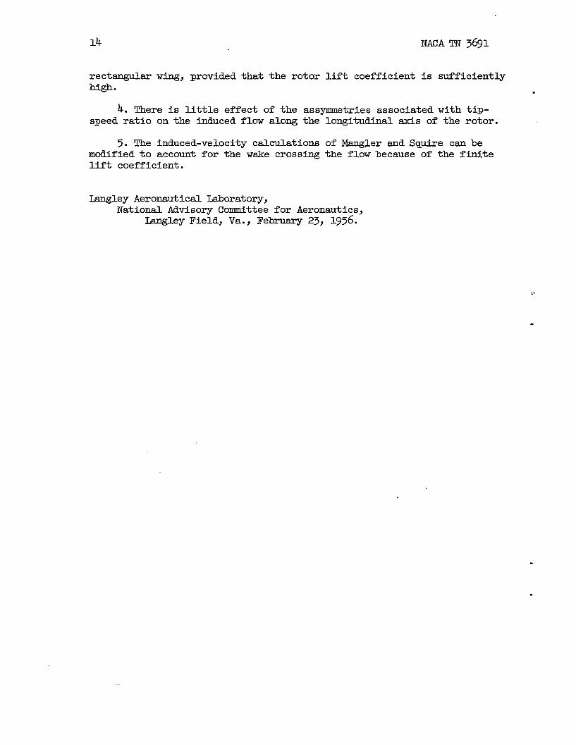
Two.differentsurveyrakeswereusedinthetests(fig.2(c)).Acalibratedfive-tubesurveyrakewasusedtomeasurethestreampitchandyawanglesanddynamicpressuresformostofthetests(fig.2(d)).TMS rakeisfullydescribedinreferenceM. ~ orderto obtaindataclosertotheplaneoftherotor,a calibratedpitchhead(fig.2(e))wasusedto surveypointsinthelongitudinalplsneof symmetryforoneflightcondition.
Theprocedureusedinthetestswasasfollows:Therotorwasfirstsetapproximatelyata predeterdnedflightcondition.Then,theareaabove,below,andbehindtherotorwassurveyedwiththerakes.Atintervslsduringthesurveying,readingsweretskenofrotorthrustanddrag,bladeflappingandfeatheringmotions,andtunneldynamicpressure.
CORRECTIONS
A floorwasinstslledinthetunneltestsectionforallthetests,andforthisconfigurationtheLangleyfull-scaletunnelhasno appreciablejet-boundarycorrection(ref.13).
In orderto correctthemeasureddynamicpressuresandstreamanglesforthefluwaboutthesupportingmechanismandfortumnelstresmangle,dataweretakentwiceateachpointin space– oncewithandoncewithouttherotorbladesinstalJed.Thedifferenceisconsideredtobe charac-teristicoftheisolatedrotor.It shouldbe noted,however,thatthisprocedureisnotadequatetiregions-diatel.ybehindtherotor.(See
.
*
_.
.
.
.
_——.—

.
.
,
.
NACATN 3691
figs.3 to 5.) Measurementsbecauseoftheeffectoftheangleofattackoftherotor
Theaccuracyofthetwo
5
madeintheseregionshavelittleaccuracyrotorontheflowaboutthetower.Thewascorrected
PRECISION
fortunnelstresmangle.
rakesisessentiallythesame.Bothmeasuredynamicpressure-within2 percentandstresmangieswithin 1/2°. Thesefigurestakeintoaccounttheunsteadinessoftheflowandthehighvibrationleveloftherakemount.Atthelowesttip-speedratio,addi-tionalinaccuracyis causedby’the&LFficultyinreadingthesmallchangesof liquidheightinthemanometertubes.Overallaccuracyintermsoftheaveragevalueofthenormalcomponentofinducedvelocitywillbe afunctionoftherotorliftcoefficient.Foreaseofreference,thefol-lowingtablegivestheestimatedoverallaccuracyforeachofthef~ghtconditionscoveredinthisinvestigation: “
I Tip-speedratio,v I Accuracy,percentV. I
0.095 *15.139 ~lo.140 flo.232 i-25
Therskesusedwereincapableofmeasuringinstantaneousvariationsof inducedvelocitysuchasmightbe desiredfora refinedblade-vibrationanslysis. Therefore,alldataaretime-averagedvalues.T’Qeexperjm.ent~restitsofreference8 indicatethatinstantaneousv~uesmaydiffergreatlyfromthemeanvaluesmeasuredinthesetests.
Duringthetests,therotortipspeedwasheldconstanttowithin1 percent.Thethrustcoefficientwasmeasuredwithin1 percent.Theskewangle,whichwascomputedby usingthemeasuredvaluesof ~ andthemeasuredblademotionsinequation(3) ofreference2, shouldbeaccuratetowithti1°.
Thepositionoftherakewithrespectto thehubwasknownwithin0.3 percentR. Becausetherotorwasoftheteeteringtype,theonlyconingwasdueto thedeflectionoftheblades.Thetipdeflectionwasestimatedvisuallytobebetween2 and3 percentoftheradius.The
.-.-— —-. ....— _ .——..—.. —.— . —_____ _.—_ ____ —_. . —,

6 NACATN 3691
datasrepresentedwithreferenceto a plsneparalleltothetip-pathplaneandpassingthroughtheteeteringpin.
RESU3SANDDISCUSSION
BasicData
Becauseofthepresentlackof information,boththeoreticalandexperimental,ontheinducedvelocitiesinmanyareasnesrtherotor,substantiallyellthebasicdataobtainedintheinvestigationsrepre-sented.Ineachcasetherotorflightconditionisidentifiedonthefigureby theskewangle X andthetip-speedratio V. TableI iden-tifiesthevsriousflightconditionsmorecompletely.
Figures3 to5 showthemeasuredstreamanglesintheflow;fig-ures6 to 8 showcontoursofdynamic-pressureratio;andfigures9 to ~givethemeasuredvsluesofinduced-velocityratio.Thefairingsofthemeasureddata,showninfigures9 to 29,areusedforthesubsequent ~analysis.
Thebasic-datacurvesarenotdiscussedas suchinthispapersince .themoresignificantphenomenahavecilreadybeenpointedoutinrefer-ence10.
DiscussionofApplicableTheory
Inreference2,CastlesandDe Leeuwpresentcalculatedvaluesofthenormalcomponentof inducedvelocityinthelongitudinalplaneofsymmetryandalongtheprincipal(X,Y,Z)axesofa rotorwitha uniformdisk10diTlf$. Reference3 usestheflowfieldofreference2 to calcul-ate theflowfieldforrotorshavingnonuniformbutcircularlysymmet-ricaldiskloadings(thespecificcasescalculatedbeingrotorswithatriangulardiskloadingandwithatypicalmeasuredmeandiskloading).
AdditionaltheoreticalcalculationsbylhnglerandSquire(ref.4)giveinduced-velocityinformationintheentirerotordiskandalsofora transverseplaneinthefsrwake. A latersectiondiscussesa methodoftransformingtheseresultsto correspondwiththeresultsofrefer-ences2 and3 exceptforthespecificdiskloadingsconsidered.
Drees(ref.5) discussessomeoftheeffectsofa finitetip-speedratioandpresents“calculationsof someoftheseeffectsat selected .
.
— —

NACATN 3691 7
.s
,.
.
pointsontherotordisk. It shouldbe notedthatthecalculatedcurvespresentedwiththedataareinthisreference.
Comparisonof
Values
notmodifiedfortheasymmetriesdiscussed
MeasuredData
ofReferences
WithCalculated
2and3
Imgitudinal planeof symmetry.-Figures30 to 33 presentthemeas-uredvaluesofinducedvelocityinthelongitudinalplaneof symmetryascompsredwiththecalculatedvaluesfromreferences2 and3.
Forthefourflightconditions,themeasureddataneartheforwardportionsoftherotorfallclosetotheflowcalculatedfortherotorswithzeroloadinthecenter.Theexistenceofessentiallyzeroinducedvelocityatthecenteroftherotorandofregionsofupwashbehindthecenterereclearlyshown.Furtherrearwsrdintheflow,justbehindthetrailingedgeoftherotor(X/R= 1.07), thereisno longermy pronouncedcorrelationbetweenthemeasuredandthecalculatedflow,regardlessof
● theliftdistributionassumedto existontherotordisk.At ~eaterdistancesbehindtherotor(X/R= 2.OTand3.14), thereseemstobe nocorrelation.Thephysicalreasonsforthislackof correlationsre.discussedsubsequently.
LOngitudindaxis.-If curvesarefairedthroughthedatainfig-ures30 to 33andthevaluesat Z/R= O aretakenfromthesecurves,itispossibleto obtainan ideaofthevariationof inducedvelocityalongthelongitudinalsx.isoftherotor.Theresults,plottedinfig-ure34, showclesrl.ythegoodcorrelationofthenonuniformlyloadedrotorcalculationsintheflowovertheforwsrdthree-qusrtersoftherotorandthedeviationbehtidthatpoint.
Figure35 compsresthemeasuredpointsoffigures34(c) andZl(d):Thesetwoflightconditionshaveverysmalldifferencesinskewangles.Thereis,however,ana~reciabledifferenceintip-speedratioandliftcoefficient.Actually,thecalculatedinduced-velocityratiosforthesetwoskewsaglesarevirtuallyidentical.Itmaybe seenthat,experimentally,thereisverylittledifferencebetweenthehducedvelocitiesalongthelongitudinalsxisforthetwotip-speedratios.Thisfactisasassumedinreferences2 and5.
Lateralax.is.-Thebasicdatamaybe cross-plottedinthesamemannerto obtaintheinduced-velocitydistributionalongthelateral(Y)axis. Theresultsofthesecrossplotsareshowninfigure36 andwecompsredwiththecalculateddistributionsofreferences2 and3. Thecalculatedflowissymmetricalsinceno accountistakenofdissymmetriesduetothefinitetip-speedratio.
——... . .——-—c _-—_ —

8 NAC!ATN3691
A wordof cautionisnecessaryatthispoint.Eecauseoftheneces-sityofmaintaininga clesrancebetweenthesurveyrskeandtherotor,itwasnotpossibleto obtaindata?mchcloserthan20percentR above “therotor.(Seefigs.30, 32, and33.) Thetheorypredictsratherlsrgegradientsof inducedvelocityatlocationsclosertotherotorthanthispoint. Inthelongitudinalplaneof symmetryitispossibleto cross-plotthedatawithsomeconfidenceby comparingthetrendsshownwellabovetherotorby thetheoryandby themeasuredpoints.At otherloca-tions,withoutthetheoryasa guide,theaccuracyof crossplotsisproblematical.Therefore,thefollowingdiscussionoftheinduced-velocitydistributionontheY-aMs shouldberegardedasbeingona lessfirmbasisthanthediscussionintheprecedingsections.
Figure36 indicatesthattherotordoeshavezeroinducedvelocityat itscenter.Thisis inagreementwiththeassumptionthattherotorcarrieszeroloadat itscenterandfurtherindicatesthatthisfactmustbeusedH theflowistobe calculatedwithmy de~ee ofaccuracy.
Figure36 also showsthattheinduced-velocitypeakontheretreatingsideishigherandfurtheroutboardthanthepeakontheadvancimgside.Thisresultislogicalwhenthedifferenceinloadingonthetwosides “*oftherotorsrecompsred.Theresultantvelocitiesatthetier portionofthebladesontheretreatingsideareverylowor evennegative,whereasthecorrespondingvelocitiesontheadvancingsidesremuchhigher.There- “fore,theload@ ontheinnerportionoftheretreatingsideofthediskmustbe lessthanthatontheadvancingside.Theouterportionoftheretreatingsidemustthencsrrya greaterloadinginorderthattheblaiiethrustmcynentremainessenti~yconstantaroundthedisk.Thus,theloadingontheretreatingsidewillpeakfartheroutboardandata highervaluethsmtheloadingontheadvancingsideofthedisk.Thisisthesametrendshownby themeasuredinducedvelocitiesandisindicativeoftheverycloserelationbetweentheinducedvelocitiesandtheloadingalongthisaxis.
ComparisonofMeasuredDataWithCalculatedValuesofReference4
Modificationof calculationsforfiniteliftcoefficient.-ManglersndSquire,inreference4Y computetheinducedvelocitiesintherotordiskandina transverseplaneinthef= wake. Theircalculatedresultsarekbnitedtovsmishinglysmallliftcoefficientsinthatthetrailing-vortexsystemleavestherotorinthesamedirectionandwiththesamevelocityasthefreestream
Theassumptionof a finiteliftcoefficientaltersthispicturein .twoways:First,thetrailing-vortexsystem-mustnowcrossthefree-stresmflowand,second,therewillbe a changeinthevortexdensity.
.
.—

xNACATN 3691
Theresultsofreferencek me easilymodifiedto accountforchsmgesandywhensomodified)willcorrespondwiththeresultsoferences2 snd3 exceptforthespecificdiskloadingsconsidered.
9
theseref-l!he
firstmodificationismerelya rotationofthefieldto accountfortheincltitionofthewake. Theincidenceangle i isthenthecomplementoftheskewangleX. Thechangeinvortexdensity,althoughaffectingtheabsoluteinducedvelocityv,wi12haveno effectupontheinduced-velocityratio ~ -
()VO-43. Therefore,thenewvalueof v msybe -vc~
foundbyusingthevalueof v/v. fromreference4 andby cal.culat~V. fromanequationwhichconsidersthefiniteliftcoefficient(suchaseq.(32) ofref.2).
Forthepurposeof comparisonwiththetiasureddataofthispaper,alltheinducedvelocitiesofreference4 havebeenmodifiedto corre-spondwithreference2 inregerdtobothskewangleandvortexdensity.
Planeoftherotor.-Veluesof induced-velocityratiointheplaneoftherotorobtainedby cross-plottingthemeasureddataarecomparedwiththecorrectedcalculatedvaluesfromreference4 infigures37to 43.Thesefigureswe discussedonlyingeneral,sincetheyindicatethessmeresultsasthepreviouscomparisonwithreferences2 and3. Thisresultmightbe expectedsincethecalculatedresultsshouldbecomparableifthesameloaddistributionssxeassumed.Theresmiblancebetweenthetypicalloadingofreference3 andpressuredistributionIIIofrefer=ence4 isevident. .
Ingeneral,thessmeextentofagreementisnoticeable(seeespeciallyfig.37(b));thatis,thecalculatedflowfieldis closetothemeasuredfieldonlyovertheforwardthree-quartersofthedisk.
Eachfigure(figs.37 to 43) showsthattheinduced-velocityfieldforpressuredistributionIII(labeledP.D.III)isclosertothemeasuredfieldonbothsidesofthediskthanthatforpressuredistributionI(labeledP.D.I). SticepressuredistributionIIIrepresentsa diskloadingwithzeroloadinthecenterandtheotherdistributiondoesnot,thisresultisasexpected.
Thisresultdoesnotagreewiththatofreference9, whichindicatesthatpressuredistributionI shouldbeusedforcalculatingtheinducedvelocitiesovertheadvsmcm sideandpressuredistributionIIIjover”theretreatingsideoftherotor.Thisresult(ref.9) arosefrommeas-urementsmadeat X/R= 1.5 andyas such,is subjectto errorbecause
. ofthediscrepancybetweentheoryandthemeasureddatainthisregion.Thepresentresultisconsideredtobemoreaccurate.
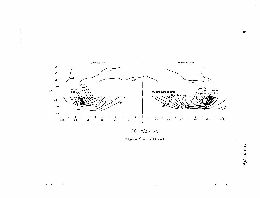
Thevaluesat X/R= 0.5 (fig.43) seemtoindicatethat,atthislocation,theerro’risgeneraldysomewhatlargerneartheouteredges
.—- —— .— ———. —

10 NACATN 3691
ofthedisk.Thisresultmighttrailing-vortexsystemwouldbedisksoonerthanthecenter.
be expectedsincetheroll-upoftheexpectedto affecttheouteredgesofthe .
Fsrwake.-Reference4 slsocomputestheinduced-velocitydistribu-tioninthefarwake. Thecomputedcontoursofinduced-velocityratioforbothpressuredistributionsinthefarwakearecomparedinfig-ures44to49withmeasuredcontoursofinducedvelocityat X/R= 2.07and X/R= 3.14 forthreedifferentflightconditions.(Noticethattherotationofthecalculatedflowfieldrequiredto obtaincorrespond-encewithreferences2 and3 resultsina verticaldisplacementofthecomputedinducedvelocities.)
Ingeneral,themeasuredinducedvelocitiesareofthesameorderofmagnitudeasthecalculatedvslues.Thisresultwouldbe expected,regardlessoftheflowpatternassumedforthecalculations,sinceagivenamountofdownwardmomentummt be impartedtotheairto obtaina givenlift.Thedistributionofinducedvelocityis,however,ratherdifferentfromthecalculatedvalues,particularlyinthecentralpor-tionofthewake. ~ somecases,thecalculatedinduced-velocityfieldintheusuallocationof short-spantailsurfacescouldbeincorrectby . ‘asmuchas 1.5v/vo.
.
Natureofthe.Flow
Atthispointthereasonfortheratherseverediscrepanciesbetweenthecalculatedsndthemeasuredinducedvelocitiesintherearwardpor-tionoftheflowis considered.Reference10hasalreadynotedtherollingup ofthevortexsheetbehindtherotor.Figures50to 52 exsminethisphenomenonmorethoroughlyforthreedifferentf~ght conditions.Thesefiguresarecontourmapsofthemeasuredlocalmeanvorticitybehindtherotor.Theintersectionoftheoutermostedgeoftheassumedwake(refs.2,3, 4,and6) withthesurveyplaneisshownineachcaseby thedashed-lineelMpse. IXtheassumedwskevortexpatternis correct,thecontoursofvorticityshouldbe alongthiswakeedge(orwithinit,dependingupbnthediskloaddistribution).
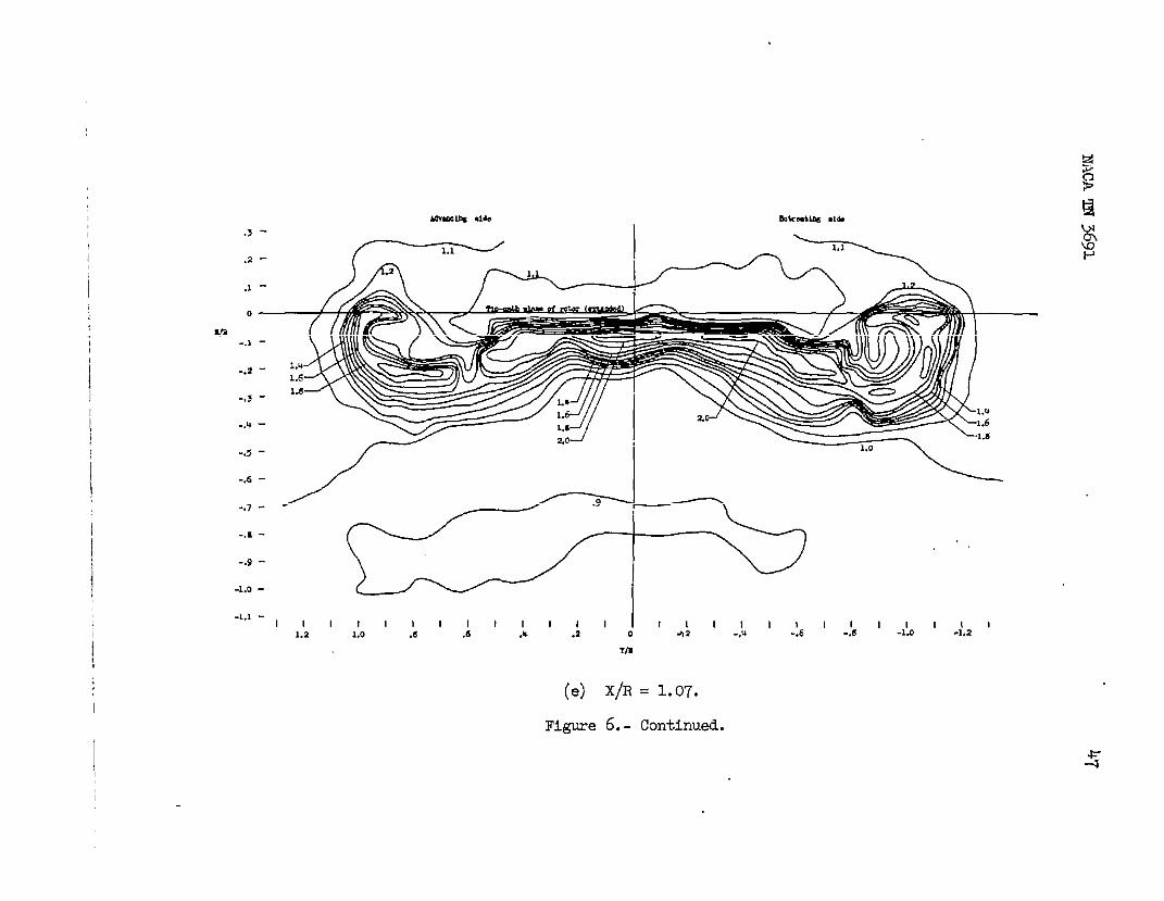
In general,thisisnottruesincethedominantfeatureineachcaseisthevorticityassociatedwiththewell-developed,rolled-upvorticesbehindtherotortips. It shouldbenotedthatthesevorticeshaveonlybeendisplacedverticallyabouthalfasfsrasthecenterofthewake.Thelowerhalfoftheellipticalsheetisessentiallycompletelyrolledup atthetrailingedge(figs.50,51(a),and52). Theupperhalfoftheellipticalsheet(originatingfromtherearofthedisk)isstillvisible “at X/R= 1.07,butitslsois completelyrolledup shortlysfterthatpoint(figs.51(b)=d 51(c)). .

NACATN 3691 fll
,.
Theshilaritybetweentheflowbehindtherotorandthatbehindalow-aspect-ratiowingisverycloseanditispossibleto drawa somewhatmorequantitativeanalogy.
Reference14examinestherollingup ofthetrailing-vortexsystembehinda low-aspect-ratiowing. Forliftcoefficientsoftheorderofseveraltenths,theroll-upisessentiallycompleteina veryshort~s-tante.Figure9 ofreference14 showsthat,foranuntwisted,rectangularwingofaspectratio 4/fi(thesameaspectratioasa rotor),andfortheliftcoefficientsusedherein(0.720,0.373,and0.122),theroll-updistancesshouldbe0.33,0.64,and1.97timesthechordlen@h,respec-tively.Itismoredifficultto determinetherateofroll-upforsome-thingas complexasa rotor,butfigures50to52 hdicatequalitativelythatitisalsoextremelyrapid.
Theseobservationsarefurthersubstantiatedbytheinduced-velocitymeasurementspreviouslyexaminedinfigures30 and32. Themeasureddatainthesefiguresshowa markeddiscontinuity(whichwouldbe expectedattheedgeofthewake)onlyh thevicinityoftheupperwakeedgeatX/R= 1.07.Fartherbehindtherotor(X/R= 2.07smd3.14),thereisnopronounceddiscontinuity;thisconditionindicatestheabsenceofa strongvortexsheetinthisregion.
Figures33(f)and33(g)seemto showa discontinuitysomewhatabovetheupperedgeoftheassumedwake. Thepreviousanalogywithlow-aspect-ratiowingsindicatesthepossibilitythattheroll-upwouldnotbe asrapidinthiscasebecauseofthelowrotorliftcoefficient(CL= 0.122).Thedifferencebetweenthecalculatedandthemeasuredflowfieldsmaybe explainedonthisbasis.Intheforwardportionsoftheflow,theellipticalwakehasnotrolledUpymd itthereforeresmiblesthewake-vortexmodelusedinthecalculations.Thewakehere,has,of course,thegreatesteffectontheinducedvelocitiesintheforwardportionsoftheflowandessentiallydeterminestheirmagnitude.Conse~ently,inthispartoftheflow,calculationsgivea reasonablepictureoftheactualinducedvelocity.
Fartherrearwsrd,however,thedistortedportionofthewakehasagreatereffectindeterminingtheactualinducedvelocity.Thecalculatedflowfield,therefore,isincre.asingl.ymoreinaccurateas itsdistancedownstreamincresses.
A shortdistsncebehindtherotor,it shouldbe possibleto assumethattheflowwillbe thesameasthatforanequivaleritwing. Themin-imumdistancebehindtherotoratwhichthisprocedurewillbe validisa functionoftheliftcoefficient.
Fromreference15theinducedvelocityintheplaneof symmetryofa uniformlyloadedrectsmgulsrwingis
..-——— - - .—...—— -—- —— — . .———— ———-— ----—— —- ——— —— - —

1’ NACATN3691
V=g
[(
H+“~” ‘S2:Z2‘S2:Z2(1) ,
~ it i’ assumedthatthelaterslcenterlineof(theapproximatecenterof
thequarterchordoftheequivalentwingandtherotorcoincideandalsothat s = 0.85Rgravityof’thevortexsystem),
v=Q&Er{i
x23-c
(o.@R)’ + x’ + “ [ 1‘2 t Z’+ (o.85R;’+ Z’ + (o.85R;’+ Z’I
E’nondimensionalized,equation
~= 0.85
{J
X R)’
0.723t [+)2+ (:)2
1
()20:723+ f}
Now
r=~‘Pm
and,forskewanglesnesr90°,
2) becomes
k1
z’+($)21() 2‘n 010.723+ #
(2)
+
r
(3) -
V. . LZ?@h#
(4)
(5)
Substitutingequation(4)intoequation(3)anddividingbothsidesoftheresultingequationby equation(5)gives
v— = 0.425=?0
{~ [o=7’3+ ::)2 + (:)2 (x)’ ‘(f)’+ o07’3: (:)’+
.
.
1
(R)‘20.723+ -
}
(6)

NACATN 3691 13
Theflowcalculatedby thisequationissymmetricalabout Z/R= O;thatis,itdoesnotallowfortheverticaldisplacementofthewake.Aspointedoutpreviously,thecentersofthevorticesaredisplaceddownwardanamount
(7)
Theinducedvelocityforthisassumedwinghasbeencalculatedfromequations(6)and(7)andis comparedwiththeflowmeasuredat X/R= 2.07dnd3.14(for p =0.1~ and X=82.3°) infigure53. As expectedintheserearwsrdplanes,itisa closera~roximationtotheactualflowthanaretheflowscalculatedonthebasisofa skewedcylindrical.wake(fig.32,forexample).
Anotherpointisworthnotinghere. Ithas,uponoccasion,beenassumedthattherotorwakemusthavemorevorticitybehindtheretreatingsideofthediskthanbehindtheadvancingsideofthedisk,sincetheunequalbladevelocitiesonthetwosidesrequiretheretreatingbladetohavea greatervalueof circulation.Thiswouldbe trueonlyatthetrailingedgeofthebladeto anobserverridingaroundwithit. However,to anobserverimmediatelybehindtherotordisk(asinthesesurveys),thesummationofvorticitybehindthediskmustbe equaloneachside,sincevorticitycannotendin space.MorecompletecontoursoflocalmeanVorticityisessentially
thau thosegiveninfigurestrue.
50to 52 indicatethatthis
CONCLUSIONS
Theresultsofthiswind-tunnelinvestigationoftheinducedflowneara singlerotorinsimulatedcruisingandhigh-speedflightareasfollows:
1.As farresrwardasthree-qyartersofa dismeterbehhd theleadingedgeoftherotordisk,thenormalcomponentof inducedvelocityofa liftingrotormayte calculatedwithgoodaccuracyby availabletheoryprovidedthata realisticnonuniformdiskloadingisassumed.
2.Rearwsrdofthisthree-xer diameterpoint,calculationoftheinducedvelocitybecomesincreasinglyinaccuratebecausethetrailing-vortexsystemrollsupveryrapidly,andthewakevortexpatternbehindtherotorisslteredfromthatassumedx a basisforthecalculations.
3.At locationswellbehindtherotor,theinducedflowmaybe cal-culatedmoreaccuratelybyassumingtherotortobe a uniformlyloaded
—,. . .—-.— -.. .___—__ _ —.—— —.— —.— _..— —.
14 NACATN3691
rectangularwing,providedthattherotorliftcoefficientissufficientlyhigh. .
4.ThereislJttleeffectoftheasymmetriesassociatedwithtip-speedratioontheinducedflowalongthelongitudinalaxisoftherotor.
5. Theinduced-velocitycalculationsofhfsnglerandSquirecanbemodifiedtoaccountforthewakecrossingtheflowbecauseofthefiniteliftcoefficient.
LangleyAeronauticalLaboratory,NationalAdvisorgCommitteeforAeronauticsj
~ey Field,Va.j Februsry23,1956.
u
.
.
.

NACATN3691 15
REFERENCES
.
1.
2.
3.
4.
5.
6.
7*
8.
9*
10.
Il.
E.
Falabella,Gaetano,Jr.,andMeyer,JohnInflowDistributionsIYom~erimentaJ-Blade-MotionDataona ModelHelicopterFlight. NACATN 3492,1955.
Castles,Walter,Jr.,andDe LeeuwjJacoboftheInducedVelocityintheVicinityEx.amPleSOf ItsApplication.NACARep.NACATN.2912.)
R.,Jr.: DeterminationofAerodynamicLoadingandRotorinHoveringandForward
Henri:TheNormalComponentofa LiftingRotorandSomeU.84,1954. (Supersedes
Heyson,HarryH.,andKatzoff,S.: TheNormalComponentofInducedVelocityintheVicinityofa LiftingRotorwitha NonuniformDiskLoading.NACATN3690,1956.
Mangler,K.W.,andSquire,H. B.: TheInducedVelocityFieldofaRotor.R. &M. No.2642,BritishA.R.C.,May1950.
Drees,J.Meijer:A TheoryofAirflowThroughRotorsandItsApplica-tiontoSomeHelicopterProblems.Jour.HeHcopterAssoc.ofGreatBritainlvol.3,no.2,July-Aug.-Sept.1949,pp.79-104.
Coleman,RobertP.,Feingold,ArnoldM.,andStemPin,CsrlW.: Eval-uationoftheInduced-VelocityFieldofanIdealizedHelicopterRotor.NACAWRbu6, 1945. (Formerl.yNACAARRL5E10.)
Gessow,Alfred:Reviewofbformationoni%ducedFlowofa LiftingRotor. NACATN3238, 1954.
Ross,RobertS.: An InvestigationoftheldrflowUnderneathHelicopterRotors.Jour.Aero.Sci.,vol.13,no.12,Dec.1946,Pp.665-677.
Fail,R. A.,andEyre,R. C.W.: DownwashMeasurementsBehinda I-2-I%DiameterHelicopterRotorinthe24-FtWindTunnel.R.& M. No.2810,BritishA.R.C.,Sept.1949.
Heyson,HsrryH.: PreliminmyResultsFromFlow-FieldMeasurementsAroundSingleandTandemRotorsintheLangleyllill-ScsJ-eTunnel.NACATN3242,1954.
DWmnce, SmithJ.: TheN.A.C.A.l?ull-ScaleWindT’unnel.NACARep.459,1933. -
Lange,RoyH.,smdFink,MarvinP.: StudiesoftheFlowFieldBehimda Iarge-Scale47.5°SweptbackWingHavingCi.rcul.a.r-ArcAirfoilSectionsandEquippedWithDrooped-NosesndPlainFlaps.NACAFM L51.IJ2,1952.

16 NACA~ 3691
13.
14.
15.
Silverstein,Ale,andKatzoff,S.: ExperimentalInvestigationofWind-TunnelbterferenceontheIbwnwashBehindanAirfoil.NACARep.60$),1937.
Spreiter,JohnR.,andSacks,VortexSheetandItsEffectAero.Sci.,vol.18,no.1,
.
AlvinH,: TheRollingUp oftheTrailing ,,ontheDownwash Behindw@s . Jour.J~. 1951,~. a-32, 72.
Silverstein,Abe,andWakeBehind
Katzoff, s.,andBliuivant,PlainandFlappedAirfoils.
.
W. Kenneth:llownwashNA.CARep.651>1939. .
.

x
I 1
Tip-speedRotorwakeskewangle,
ratio, p x, aeg
wT4PUZ I.-F’LICETCONDITIONS
CL CT Disk loading,Equivalentflat- Angle of
J& lb/sq ft platearea, f, athck,Sq ft a, deg
0.720 0.CX)320w 1.91 2.77 -9.2a.3& a.03373 w a2.18 2.34 -1.1a.373 a.m3p m a2.~ 2.79 -5*3.U22 .(X)321.450 1.55 1.35 -9.5
%Ihe seeminginconsistencybetweenthe valuesof rotorlift coefficientand thrustcoef-ficienton one handand the valuesof averagedisk loadon the otherwas causedby a slightdifferencein the densityof air at the differenttimesdurfqgwhichthe testswere run.

%
I v
i
-f
Figurel.-Coordinatesystemof rotorand wake. Arrmm indicatepositiveftlrectiona.
.

NACAm-3691
.
I .=— .—.._ ._. ..—=
1’f’----,%+‘;Q“‘7“”I
.-,7 =- j.-
1 -–”’* ‘“ ‘%--
F ‘ - ,=.
I ]\. ”
rll’.-——,.
1’
+\
Ii
\
,/’‘\.
‘$ . -—*\..+v./’- ““Y
M!z-..#-“.
,,
..:--.~-—:“B?———---:...-
—
(a)Testsetuplookinginto
Figure2.-Eq&~nt
L-83264.1entranceconeoftunnel.
usedin surveys.
-. . . .... ...—.— ~ —-- —.—. --- . -—.-— -.—— — ——

I
I
I
I
(b)Rotorblade. L-91957
me p.- continued.E
;u$
.
* c *
,
----- .— — I
II
~ (c)RakesE@ mounted. cm .wrvey-cwr18geram.L-87200.1
I) R&we 2.- Continued.

I
(d)End of one tube 01’fiw.~ r~e. L-91956.1

NACATN3691
.
(e)~ pitchhead.L-87202.1
23
IiYgure2.-Concluded.
. . ——. .. . —. ___ —.— — -.. .— ______ _ _ ... ... . .- -—.—_. .

.3-
Advanoi.ng Slds
Tlu-path plane of rotor (extended)
YjR
9.4 0 qo qoSoale
Devlatlon, dog
(a) X/R = -1.0.
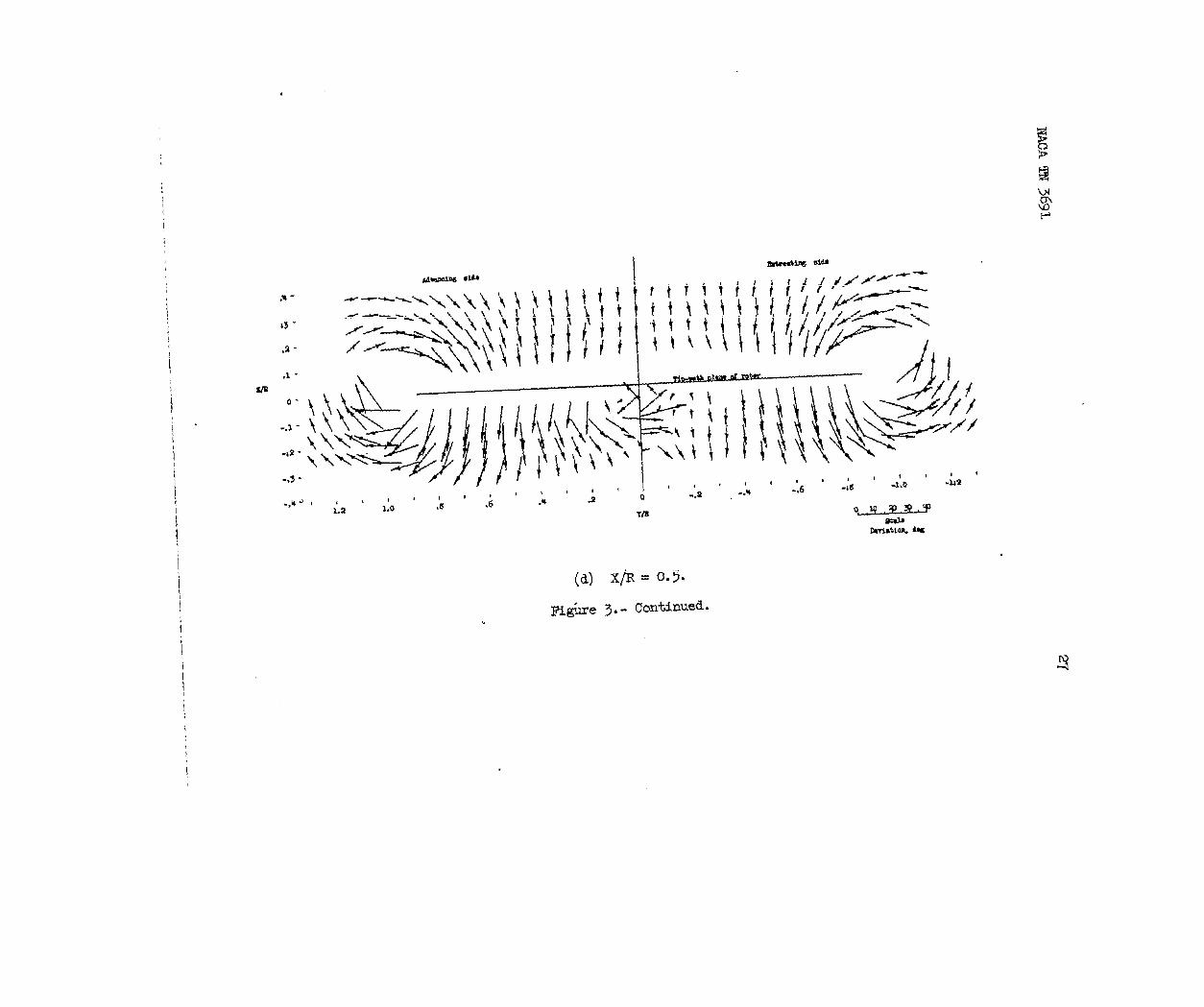
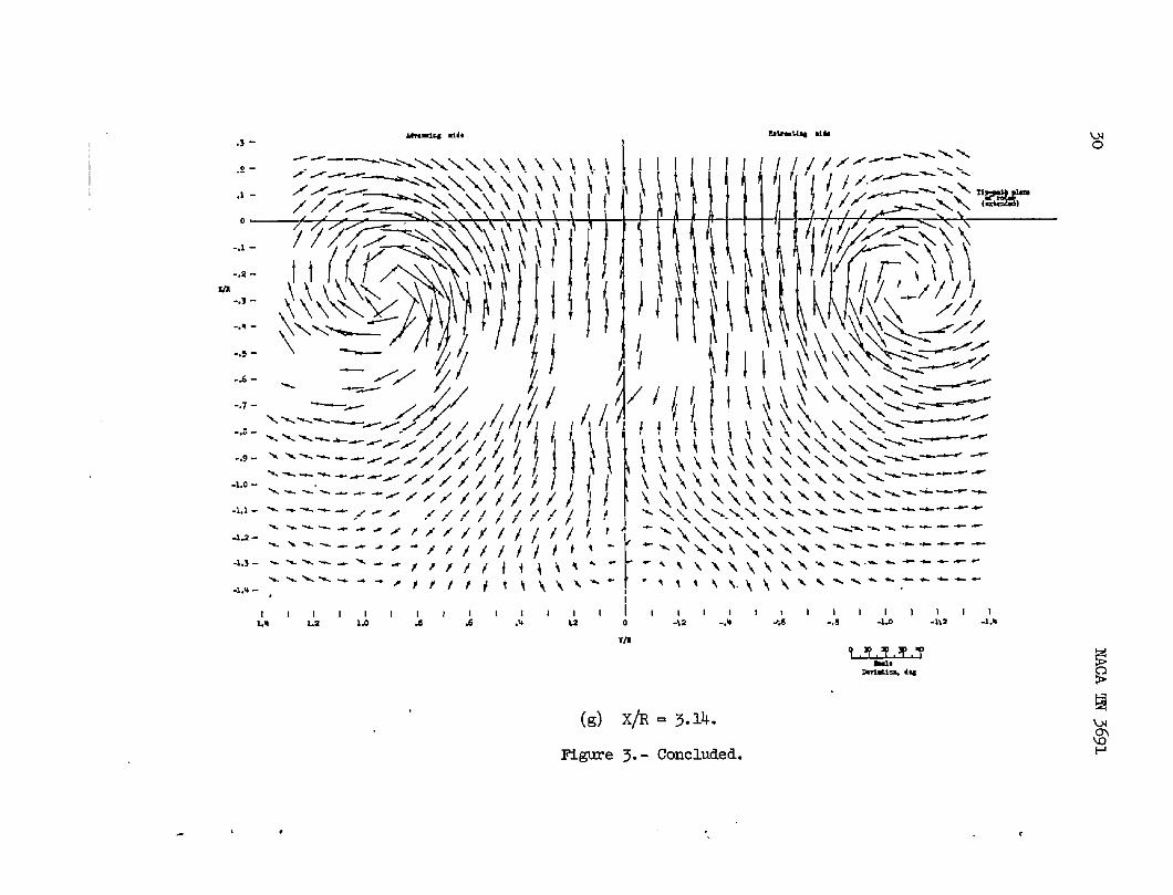
-e 3.-M5asurea abeam angles in vicinity of rotor. Horizontalaad HtiCd coru@Ients
vectorsrepresentyaw and pitchangles. Base of vectoris at pointof measurement.X =p = 0.095.
, ‘ x ,

I
I
II
I
1
.s-
w.-
0-
-u- \\
4-
LIn
I
(b) X/R = -0.~.
IMgure3.-Continued.I
I
l’,

,U -
13-
,* -
(c) X/R=O.
.
Figure3.-Conti.nufd.
.
1
.* -
Z3-
.1-
.1 -
S/mo-
-.1-
+2 -
. . ... . .,, . 1
,~1,,1, ” :8 .; .* .2
1.2 Lo
am
. .!2 -.5 ..”
i

I’m
,>-
,s -
‘aI -
0—
-.1 -
-, ?-
-J -
-. 4-
-, 5-
5-a -
-.7-
-.6-
-.9 -
.L.o -
-u -
.1.9 -
-LJ -
-w -
1111, 11118, , ,-, e -.* .; .3 -14 -La -w
(e) X/R = 1.07.
i?P
E!
g
t , , t

I
I
i
.3--m CM4
-2.““---\\\Y\\\Y ‘
H“ -—’--ix+.1-
/ /#/_
///
-,1-
->2-
-, 3-
Ui
..4-
-.5-
-.6-
[l f#//,— /d—. - -
.\\\
.\\\
{111, ,,, ,,, ,1,14 1,2 ,,0 .s
1!.6 .4
11 l,,,Z 0
11, ,,, , ,-,1 -.4 -L * -1,0 -I, *
VI4>4
uo
,x-
.1 -
0-
-.1 -
-,a-m
-.3-
--- -
-.5-
-h -
-.7-
-.3-
-, 9-
-LO -
-L] -
-1.U -
1 I 1 I 1 I 1~ 1111111111 111A A 1.! !0 4 .: A 42 -.@ 4 -.8 -lIa -I.*
Tim
(g) x/R = 3.14.
F@vre 3.- Concluded.
.

I
{
I
I
A4mrminE aide
.4- *IV.
,., ,
.3 -\bb*
.2- bbbb
.1-
z/R
. ,
44
i
Al-.1-
\b
-a- \L
AL-.s -
I I I08
i
b
\
A
I.4
b Lb+
\ lL\
1,,4
I I I.s o
Y/R
(a) X/R = -1.0.
Retmattng side
.
.
●
,
‘~msaab.
Devle.tlcm, de~
F&we 4.-Mmaured 8treamanglesin vicinityof rotor. Horizontaland verticalcanponentsofvectorsrepresentyaw andpitch angles. Base of vectoriB at point of mxwuremnt.~ = 0.140.
x= 82.3o; :

m
,Ll -<r’
?3-”./
;2-, ,
,1 -
0-
1
-.L -t
. .a- \
,+ -
I1.2
.
,
I
b
\
\
\
I1.0
.
.4
~ am
>. ..,., ,,,
v. . . . . . ,,● +-.,*, ,,<< .,,,, ,,
Ill.s
II.’6 .!4
1111111 II 1 I-M -. * -, 6 .4 -:.0 -;2
IIw
(b) X/R = -0.5.
Flgme 4.-Contin@l.
, , , I

“.
x
I
i
II
.1-
m0-
fip#b plm d .kr,
-.*-, ,,, , ,1)/)) )1 llllwllllllla Idlt19 1,0 a .6 ,il %2 0 -. 2 -. e ..6 -.s -1,0
T/l
“aJJ?
mmmuoq 4W
(c) X/R = O.
Figme k.- Continued.

.,1- 1
1111111 l~tl 1111111161 :61-;,0’-1’2 I..4 -
1.2 1,0 .8 .6 .14 .2 0 -, a -. @ -. .
(d) X/R = 0.5.
IYgureb.- ContLuud.
, .

II
I
I
I
I
I
I
-.1-
-,2-
Lm-.3-
-.* -
-.Y-
-.6-
-.7 -
-,a-
-.9-
● l. O-
-L1-
1111111 1 11.- L2 1,0 a : 1111 11111 I I 1 1
+ s 0 -,2 ..4 .!6 -’d A +!2 -[u
(e) X/R = 1.07.
Illgure4.-Continued.

.,1 -
-,a-
-,3-
.,Q -
-.5-
-.6-
-.7-
4-
+-
-la -
4.1-
\\\\\\
1111111 Ialllll I((lttll J&l-J, I-;*
1.4 1,1 1.0 & .6 .4 .2 0 -.2 -A .; -.8
(f) X/% = 2.07.
Figureh.- Continued.
. .

UI
!2
111111 II 11111 1,,1,1111 11111
1A LX 1.0 @ ; ,U .2 0 -.2 -,@ .; -.s -l@ -1,2 -hQ
m
(g) X/R =3.14.
Figure4.- Concluded.

,U-.
.3- “
.2-.
.1 -
mo-
-,1 - ‘>
.,1 - ,
-.3-’
~ti.. . . . . . . . ,.,
. . ...”. .,, ,,.
., . . . . . ,., .,
. . . . . . ,,, ,,,
,,
,,
,,
.!
,\ .-*,,, ,,,
b, . . . . . . . ,,,
. . . . . . . . . .
. . . . . . . ,,, ,
11)1111 II1.s LO .6 J ,~
,,,
>,?P,,
,,,
Ill.1
,.
,!
. .
.,
.
.
.
#WL?HU4 dti
,,, ,,, ,
.,, ,,/
,,, , ~?+
.,, ,,, #
.
.
.
,.
. . .
. . .. . .
.,8
.
,,,---~ ~.,
\\ %-----” .
\ t-..~....
, <. .-..,. .
1111111-a -1,0 -L2
(a) X/R = O.
sentyaw andpitch@es. Baae of vectorisFigure ~.-’ Measured streamaagleain ticinityof rotor. Horizontaland verticalcomponentsrepre-
at pointof mmaurement. X= 83.9°Jp = 0.232. F~
* , . <

,U -
.3 -
,2 -
.1 -
m0-
-.1 -
-.2 -
-.3 -
. .
./
,.
.,
,,,
r?,,,,,,.
11111111 III!L2 1,0 a .6 .9 ,e
(b)
Figure
0
m
,,
,,. .,,
,
,.*
,!.
,,,
,,,
Wmtik mm?,, ,,, ..+.r.trf,- ..P,, ,, *,, *,
, .? ttf t*--
,
.
.
.
..
/,,
,., , ,,, , , tk~=-”””
1 1! 1111) III..2 -.+ -. 6 -.6 -Lo -L2
L&fIulhim, 446
X/R = 0.5.
5.- Contdm.zd.
I

1)111111 1 11111I.w L1 1.0 .9
111111111,1 ,11,1!6 * .2 0 -.s --- -.6 -d -LO -L8 4A
T/l
WI% 4
(c) x/R = 1.0’-(.
Rlgure 5.- Continued.
. .
!2
. #

a-- *
J-, ,,, . ..w -<,
..1 -
n-.s-
-.3 -
-.* -
-.5 -
-.6 -
)1111111 1 I Illl,U 1,1 la .I ,: .: .2
TO
(d) X/R = 2.07.
Figure 5.- Continued.

g
-J-
.2-Zn
-.3-
-.*-
-.5-
-.6-
(e) X/R = 3.14.
Figure5.- Umcltia.
. , *

khCOldllg aide Retreatingaide.4-
●3 -
,2-
●l-
iii/R !
0 1 Tip-ma th plane of rotor (extended)
111111111 1~11.6 e4 a o -of! -, 4 - ●6
Y/’R
(a) X/R = -1.0.
Fi&ure6.-Contoursof dynmic pressure q/~ ~ the vicinityof the rotor. x = 75.00;v = 0.095.
El

/1
1
1
1111111 Ill Ill 1,111, I1.2 1,0 .8 ,6 .4
11111.2 0 -G? -, u -. ! -.’s -LO -L2
m
(b) X/R = -0.50.
~gme 6.-Continued.
. . .
El
.

I
It
I
h-
.3-
,2-
.1-
\
Z1’n0-
-. 2-
-, 3-
“1-’/’ /---111111 11111 11111
1.2 1,0 ,0 .; ,* .2 { .)2 -. k!
m
II-.6 4
(c) X/I? = o.
-JoI
-1 !2
~gure6.-Continueci.
I
\ (’.1-
Zm0-
-.3- 1111111 I 1111
1.2 1.0 .s A .Q ,2
(d)
Figure
ltllll I I I I0 +2 -. * -.! .!s 4 -1!2
m
X/R = 0.5.
6.- Conttiued.
, . .
t
I
II
I
1
-* tida.3
bkmtti ,Ib
.2
,1
0
m-. 1
-. 2
-, 3
-. @
-.5
-.6
-. 7
-. s
-, 9
-1.0
-1.1 -1111111 111111 JlJ21111611g l-J41-J,2,
1.2 1,0 ..5 .6 .& .2 - .M -. -.
m
(e) X/R = 1.07.
~gure 6.- Continued.

ml -.1-
.,2--.3-..v--.5--.6--.7-7-1-
-.9-
.1,0 -
-1,1-
.La-
-1.5-
.Lw -
/
I1!1
IL’0
I .! ‘.d’.!” J’
mk-ulq, ,Iti
&“’Ill
A -’6 ‘ -’!9I
-,0 -Lo ‘ L ‘ -i,,
Lm
;
(f) X/R = 2.07. El
Mgure 6.- Continued.u$
, , . ,

m
.1-0
~
-.1-
-.2-
-.z-
..W
-.5-
-.6-
-i.z-
-l, Y-
-1.W
.1.5-, ,,, ,,
1,1 1.9 a1111111 111111111111 II
.6 ,% .2 0 -,2 -.! -.6 -A -1.0 -1.2rn
(g) X/R = 5.14.
Figure 6.-Concluded.

MluOiM rid,
,a- Imwlrq aid,
,1
0
-, L
m ‘“2-,3-. 4
-.5-
-.6-
-.7-
(“.4-
11111,2 1,0
I,s
I Ill Ill Illa 0 -. 2
In
(a) X/R= l.07.
1111111 II-,4 -..5 ‘-@ -hi -i.z
F@me 7.- Contoursof dynamicpressure ~~ inthetinicityof rotor. x=82.30j~ =cI.140. ~
la
$
. , .

. .
u-a
1
.1
0
-.1
-.2
-.3
-,’4
-.5
-.6- 1
-.7-
-.s-
-. 9-
-1.0-
111111 111111 111111.2 1.0 x .6
1111111,@ ,2 0 -a -.U *8 -1,0 -1.2
(b) x/R=2.07.
Figure7.-Continued.
ulP

VIro
-.1-
-.z-
-s-
-.6-
-.7-
.6-
+-1
1,2
/
1111 11111 1111111 I;6
I1,0 .8 .* ;1 0 -, 2 -. u -. 6 ..6 -1,0
w
(c) X/R = 3.14.
Figure7.-Concluded.
II-u
I-w
, . . , ,

m
Mvamiw #l&.
Edi-mtiw lib
.1-1.11,2
0 //
~T*M u!plm of rata? (U.krdEd)
(
-, 1-
-.2-
-. 3-
.,4-
1111 1111 I 11111111111 I1.0 .8 !6 .4 ;2
(EJ
~gure 8.- Contoursof dynamicpressure
P
o -.2 -.w -.6 -.6 -1.0
YLU
x/R= 1.07. b
q/qo IIIthe vicinityof the rotor. X= 83.9°;
= 0.232.

Y-
o Tipqm U plud of rdor (dmltd)
-, 1-
a-,2-
-.3-
-, Q- 1.,
-. 5-
11111111 II 11111111 Ill1,0 .$ .6 .U .2 0 -.2 -.N ~.6 -.8 -lLO
YrB
(b) X/R = 2.07.
l?igure 8.- tintinued.
. , , ,

1,
I
I
-, 1-2/74
-.2-
-.3-
-.~-
-,9-
I
I
11111111 I1,0 ,s %6 ,4 .2
(c)
F%gure
11111 .llll ill l!o -12 -. 14 -. 6 -. 8 -1,0 -liz
Y/m
X/R = 3.14.
8.-Concluded.
I
,
I
I

v/v.
.
Advancingside Retreatingside
1“
o
-1
1
0
-1
1
0
-1
-11
(a) z/R= o.32.
(b) z/rt=o.250
(c) z/R= o.18.
It@re 9.- Masured
(d) Z/R= O.Il.
valuesofx=
induced-velocityratio v/vo. X/R= -1.0;75.00;~ = 0.095.
.
.
—

NACAm3691 m
v/v.
Advancing side Retreating 8ide
10
.. .-----1-
(e) Z/R= -O.08.
1
0
-1 ‘
10
-1
(f) Z/R= -O.14.—.. . ___ — ——.——
(g) “.Zpl = -0.21.
1
(h) z/R= -o.28.
IE@ure9.. fhnctied.
●
� ✿ ✎�✍✍✎ � ✎✎�✿✿ ✿✿✿✿✿ ✎✿ ✿✿✿✿✿✿ ✍ ✿� ✿✿✿✿✿✿ ✿ ✿

58-.
NACATN3691 ,
Advancing side Retreating side
1
0
-1.
(a) z/R= o.36.
(b) Z/R= O.30.
v/v.
1
0
-1
1
0
(c) z/R= o.23.
Rtgure10.-
10@
Measured
05 o
valuesx
Y/R
(d) Z/R= O.16.
ofinduced-veloci~= 75.00;~ = 0.095.
R-0/ -10 @ -10~
ratio v/vo.X/R= -0.5;
.
.
.
.
.
.
.— . . .
.

59
v/v.
Advancingside Retreatingside2
1
0-1-2
(e) Z/R= -O.07.
2
1 I
o ~
-1 ‘
(f) Z/R= -0.13.
1
0-1
(g) Z/R= -O.20.
.11.5 1.9 05 0 -05 -109 -1.5
Y/R
= -0.27.
Concluded.
--..—— ————-——-—— —.

60
Advancingaide Retreatingside1
0
-1
(a) z/R= o.38.
2-
1
0 ‘-1
v/v.
2
10
-1
2
‘1
0
-1
(b) Z/R= O.31.
(c) z/R= o.25.
1.5 100
FigureIl.- Measured
05 0 -05 ‘-1.() -105
~jR
(d) Z/R= O.1~.
valuesofinduced-velocityratio v/vo. X/R= O;x = 75.00;~ = 0.095.
.
.
.
.
“
.
— .——.———-—

NACAm.3691
v/v.
3210
-1-2
2
1
0
-1
2
1
0
-1
1
0
-1<
Advencingside Retreatingside
(e) Z/R= -O.w.
(f) Z/R= -O.14.
(g) z/R= -o.20.
1.5 1.9 05
(h)
?Hgure
o -05 -100 -105Y/R
\Z/R= -0.27..
Il. - Concluded.
.. . ..— ——— —-— ——— -— —---—“———”—— —— ..—.— —— ----.—- —- —-- ------—— -~-—- -——
NACATN369i
Advancingside Retreatingside
2-
1
0
-1
(a) Z/R= O.37.
2
1 .....-..
0
-1
(b) Z/R= O.30.
v/vo2.
1
0
-1 “
(C) z/R= o.2k.
z
1 —
o
-1105
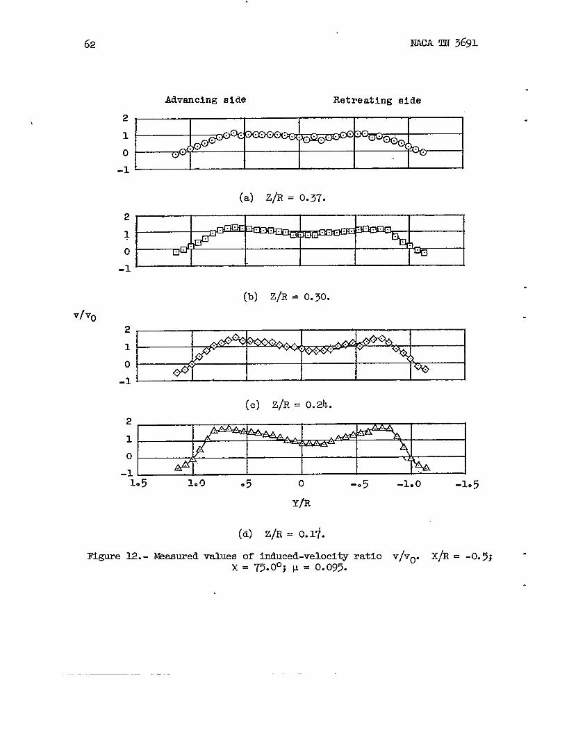
E@ure 12.-
10CI 05 0
Meamredvaluesx
Y/R
(d) Z/R= O.1~.
of induced-veloci~= 75.00;p = 0.095.
-05 -1.0 -1.5
.
ratio v/vo. X/R= -0.5; -
.

NACATN3691 . 63
543210-1-2-3-4
4321
0.-1
v/vQ -2-3
Aavanolng eide RetreatiDEside
(e) Z/R= -O.05.
/’P
Lb
# ‘
\ \p / > &
t
(f) Z/R= -O.12.
-2J I I I I I I
k) @=-o .19.2
1
0 4’ $’-1
1.5 1.0 .5
(h)
Figure
o -0 5 -1.9 -1.5
Y/R
z/R= -0.25.
12.- Concluded.
. .-z ..— —-————.__— . . . . ..-—
. . . . . .— —----- -— -—-———--——
..—
r

64
v/v.
Advancingside Retreating
NACATN3691
side
2-..........-
1-
0“-1 ‘
3210
-1
3210-1-2
32
10-1-2
(a) z/R= o.26.
(b) Z/R= O.19.
(c) Z/R= O.12.
1.5
Figure13.-
100 05 0 -05 -1.0
Y/R
(d) Z/R= 0.($.
Wasuredvaluesofinduced-velocityx = 75.00;p = 0.095.
-105
.
.
.
.
.
.
ratio v/vo. X/R= 1.07.
—

NACATN3691
v/v.
Advancing aide Retreatingaide4 I .A I I I I I3 I I I2 v 1
/ Iv” I1 i[
II
I I I YIi
-1-2
-2 J 1 I I I I I
(e) Z/R= -O.01.
543210-1-2-3
(f) Z/R = -0.08.
4’3 A
2 1-1 /. I0 /
-1 4 !-2 t V
v
-31.5 1.0 85 0 -.5 -1.0 -L*5
(g) z/R= -o.14.
Figure13.- Continued.
--—— ——.-—- --——- —— —--— -———-——- —. —-— —

66.
NACATN3691
.Advancingside Retreatingside
43210
-1-2
(h) Z/R= -0.21.
3210
-1-2
.- (i) z(R=-o.28..--,..-”2
“1
0 <-1105 1.0 OS 0 -05 -1.0 -1.5
Y;R “
= -0.34.
Continued.
.
.
Figure13.-
r..
———

NACATN3691 67
v/vo
2
10
-1
AdvancingBide Retreatingaide
(k) Z/R= -O.41.
210
-1
(1) Z/R= -0.48.2.10
-1
(m) Z/’R= -O.%.
1
0-1
(n) Z/R= -0.61.
2
1
0 — .
-1 1.5 100 050. -05 -1oo -1.5
Y/Ii
(o) Z/R= -0.68.
~gure 13.- (!ontfnuedo
-. .— _. —. —.-— — _._. .— . .. ——. ——

v/To
1
0-1
Advanoingside Retreatingside
(P) Z/R= -O.7k.
(q) z/R= -o.81.
(r) Z/R= -O.88.
“.. . . . . .
(S) Z/R= -O.gk.
105 1.0
—— —.
(t)
ItLgure
0 -05 -100 -105Y/R
Z/R= -1.01.
13.- Concluded.“
.
.
.
.
.
WA Im3691
tivenaing aide Retreating side
69
v/vo
.
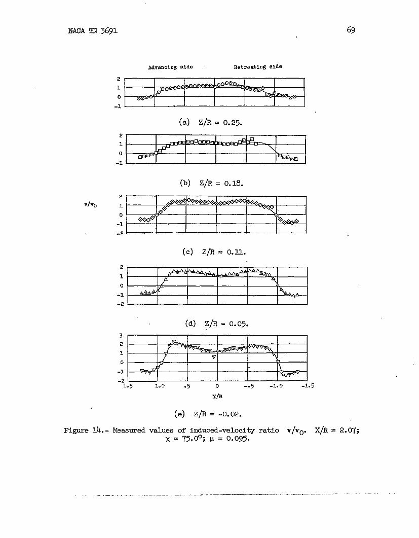
l&jurelk. -
210-1-
(a) Z/h= O.25.
210-1L
(b) Z/R= 0.18.210
-2
210-1-2
3210-1
(c) Z/R= O.Il.
(d) Z/R= O.0~.
1.5 1.~ .5 0 -05Y/R
(e) Z/R= -O.02.
valuesofinduced-velocityx = 75.00;~ = 0.095.
-1.0 -1.5
ratio V/Vo. X/R= 2.07;
-——. -—..— ——

70 WA IIJV3691
v/vo
mvanaing side Retreating aide
43210-1-2
(f) Z/R=-O.@.
5t432 4 < H1 / 4
0 /
-1 / {
-2 .-3 1
(g) z/R= -0.16.43210-1-2
-31.5 100 05 -100 -105
YOD ’05
.
*
(h) Z/R= -O.22.
[email protected] Continued.

NACACIT?3691.
71
v/vo
Advancingside RetreatingBide
3210
-2
.(i) z/R= -o.29.7J
2
1
0-1-2
(j) Z/R= -O.36.
2110-1
(k) z/R= -o.42.
3! I I I } I II II210
%!5PEW] I t I 1-% I. ..10!) ●5 o. -05 -100 -1.5
Y/R
. (1) Z/R= -O.49.
Figure14.- Continued.
—. — —— —__ -. —

72 NACAm3691
Advancingside Retreatingside
(m) Z/R=-O.%.
2“1’
0“
-1‘
(n) z/R= -o.62.
v/v(j
1
0-1
21
0
-1
(o) Z/R= -0.69.
1*5 0 -05 -100 -1.5
Y/R
(P) ,z/R=-o.76.F5gure”lk.- Contigued.
.
.
.
.
—————--- .—

NAOATN3691 73
Advancingaide Retreatingside
2 .–.-.
1
o
-1
(q) z/R= -o.82.2 ..——..
1 ... ...0
-1
(r) Z/R= O.@.
v/vo
1-
0-1
(s) z/R= -o.96.
1
0-1 ‘1*5 1.0 05 0 -05 -100 -105
Y/R
(t) z/R= -l.02.
~gure 14.- Conctided.
— —._______ -...—._ —_—_— .—-— ——. ~——— - —.—— —.-

NACATN3691
Retreatingside .
21
0
-1 -
(a) Z/R= 0.23.
2~10
(b) Z/R= 0.17.v/PQ
.
(c) Z/R= 0.10.
32 1.
1
0-1
-2105 Lo 05 0 -05 -1.n -la5
Y!R
(d) Z/R= 0.03.
Figure15.- I%suredvaluesofinduced-veloci~x = 75.00;~= 0.095.
ratio v/vo.X/R= 3.14.

NACATN3691 75
Advanolng alcle Retreating aide
321o-1-2
(e) Z/R= -O.03.3210-1-2
v/vo
321.0-1-2
43210-1-2
(g) Z/R= -O.17.
I
IJ
-31.5 1.9 .5
(h)
Figure
o -.5 -1.9 -1.5Y/R
Z/R= -0.23.
15.- Continued.
.—_______ _.. _ -—. ..- ——— ———.—

.76.
‘?/ V(j
Aihncing side Retreatingside
43 I
I21
1{
1- 1 1“ I~
-1 I~ I I I I k-2 I
(i) z/R= -o.30.3.2 A
1 *
o /
-1 /H I.J-2
(j) z/R= -O.37.32 A
10-1-2
(k) Z/R= -O.43. ~
210
-9–-1.5 1*CI 05
(1)
Figure
o -.5 -1.0 -105
Y~R
Z/R= -0.50.
15.- Continued.
.
.
.
.
\

NACA~ 3691
Advenclngside
77
Retreatingside
2
1
0
-1
(m) Z/R= -O.57.
2“
1
-1- “
(n) z/R= -o.63.v/vo
21
0
-1 “
(0) Z/R= -O.70.
2
1
0
=.11.5 1.’0 05 0 -o 5 -100 -1.5
Y/Ii ‘
(P) Z/R= -O.77.
Figure15.- Continued.
..,——____ -.. ——_.. . ~—. - . ..— — - . —- —- —-— —

78 NACATN3691
Advancingside ‘ Retreatingside
21
0
-1 ●
(~ z/R= -o.83.
21
0I-1 +
(r) Z/R= -O.90.
v/vo
2] I I I I I I1
0
(S) Z/R= -O.97.
21
0-1 J I I I I I–-1.5 o -05 -1*O -105
.
.
.
.
m
(t) Z/R= -l.03.
l?igure15.- Concluded..
———.—— ——---—-
NACATN3691 79
.
.
Advancing side Retreating side
o-1
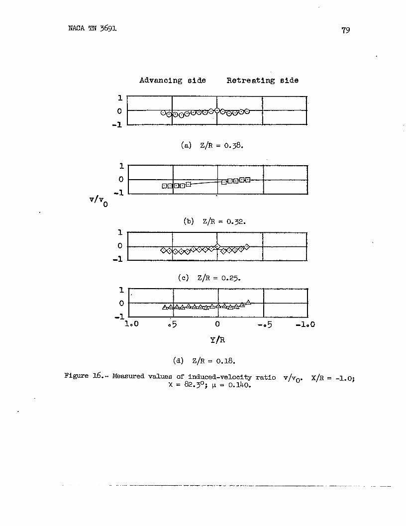
(a) z/R= o.38.
1
-1v~v
o
1
0-1
1
0
(b) Z/R= O.32.
(C) Z/R= O.2~.
I I I I I‘loo 05 0 -05 -100
~~R
(d) Z/R= O.18.
Figure16.- Measuredvaluesxofinduced-velocityratio v/vo. X/R= -1.0;= 82.3°;w = 0.140.
— — ..— — —. ...— ———_
80 NACATN3691
10
-1
1
0-1
1
0-1
10
-1
Advancing side Retreating side
.
.
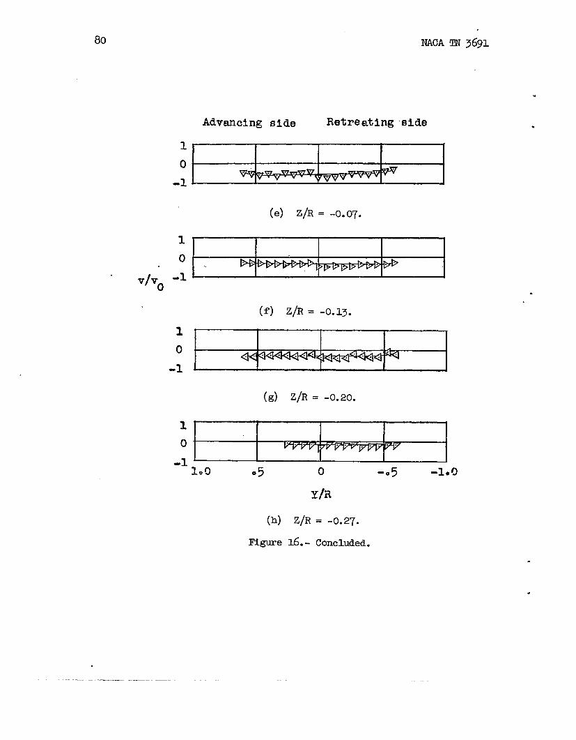
(e) Z/R= -0.07.
I I I I
.
(f) Z/R= -().13e
(d z/R= -o.20.
1.9 05 0 -o 5 -100
(h) Z/R
Figure16.-
= -0.27.
Concluded.
.
.

NAC!ATN3691
Advancingside Retreatingside
1-0 ..--”..“.
-1
(a) z/R= o.36.
1
-1
(b) Z/R= O.30. “
v/v.
1
0
-1
21
0
. . ---
(c) z/R= o.23.
..- “
-1 J1.5
I I I I I 1.
ltQure17..
1.0
Measured
05. 0 -a 5 -i. o -105
Y/R
(d) Z/R= O.18.
valuesofinduced-velocityx= 82.30;~ = 0.140.
ratio v/vO. X/R= -0.5;
—-————..—- .— -——. . .— .. ..—_— ..—

82 NACA‘rM3691
v/vo
Advancingside Retreatingside
21
0
-1
-2
(e) Z/R= -O.07.
1I
-1I
1
0-1
10-1
(f) Z/R= -O.14.
(g) z/R= -o.20.
I
.
.
.
–1.5 1.0 .50 -05 -1.!) -1.5Yh
(h) Z/R
ltlgure17.-
= -0.27.
Concluded. ●
✎
—
Advancingside Retreatingside
1 . . . . . .
0-1 r
(a) Z/R= O.35.
210
-1v/v.
(b) Z/R= O.29.
21
......0
-1-
(c) Z/R= O.22.
21
0-1 “10~ 1.9
Y/R
(d) Z/R= O.21.
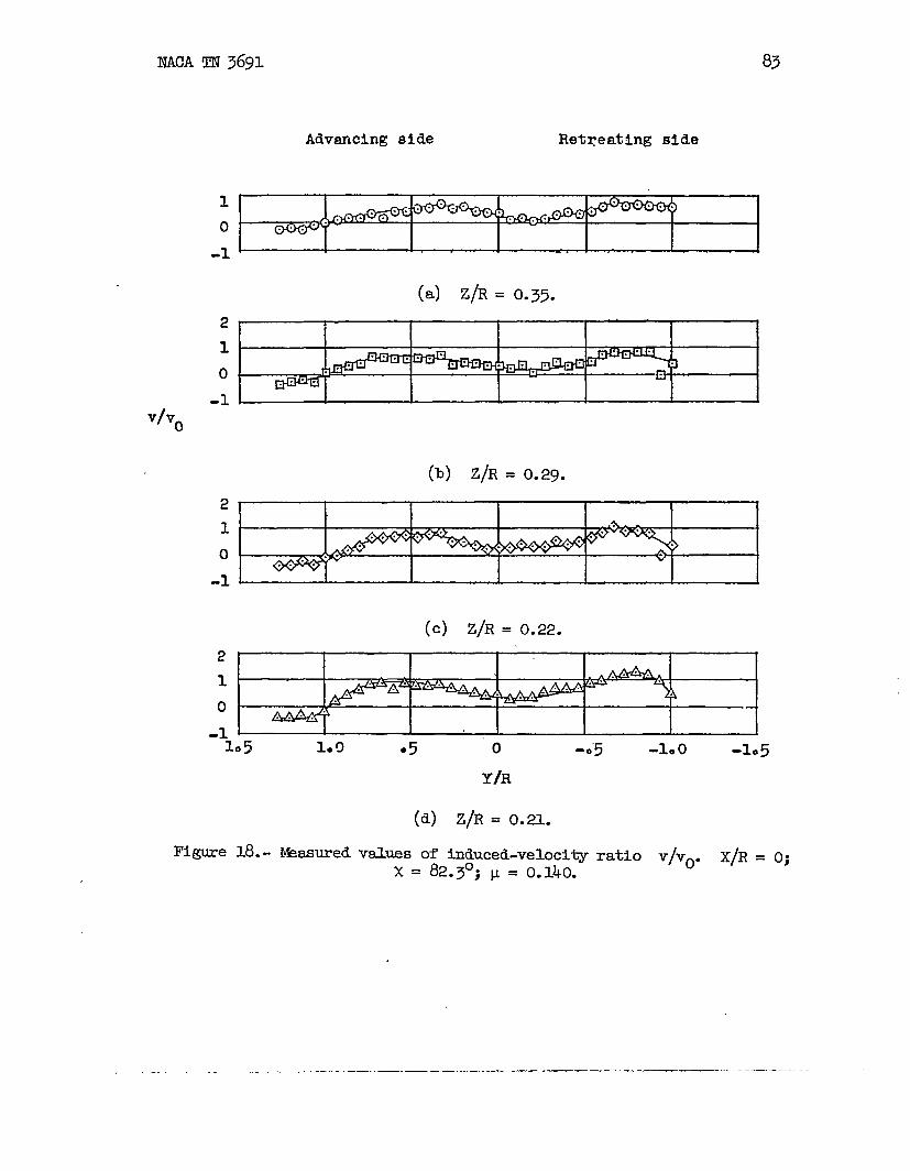
Figure18.- Wasuredveluesofinduced-veloci~ratio v/vo. X/R. O;x= 82.3°;~ = 0.140.
-..——. ——-. —.. ..— — ——— — .——. —

IW2Am 3691
21
0-1-2
210
-1v/v.-2
2
10
-1
1
0
Advancingside Retreatingside
(e) Z/R= -O.07.
(f) z/R= -o.14.\
.“” .
(d z/R= -o.20.
1.5 1.af3 05
(h)
Figure
o -e 5 -1.0 -105
Y/R
z@= -0.27.
18.- Concluded.
.
.
.
— —

NACAIm 3691 85
Advanoingside Retreatingside
v/v.
3210
-1
3210
-1
3210
-1
(a) z/R= O.Jo.
. . ..
(b) Z/R= O.~.
(c) z/R=o.27;3] I 1 I I I i210
-1 -1.5 1.0 95 0 -05 -1.0 -105
IRI_gure19.- Measured
Y/Ii
(d) Z/R= 0.20.
valuesofinduced-velocityx= 82.3°; I.L= 0.140.
ratio v/vo.X/R= 0.5;
. . . . . .. . . . . ——_ ————.—._. . __ __ _____ —— -.—— —.

\tiA m 3691
AQvenalng aide Retreating Bide.
v/vo
0
43210-1-2
-3
(e) Z/R= -O.W.
41 I I I I I I
(f) z/’R=-c).l3.32 1 A
10 P-1-2 L
(d Z/R= -0.20.
210 7--1 7~
-2 I1.0 .5
(h)
Figure
o -05 -1.9 -1.5Y/R
Z/R= -0.27.
19.- Ccmcluded.
.
.
.
. —

NACATN3691 87
Adwmoingaide Retreatingside
2
1’0 I. w I I I I I* I
(a) z/R= 0.23.2’
1“~ —o“ J
-1-
v/v.
32
1
0-1-2
432
1
0-1-2-3
(b) Z/R= 0.17.
(c) Z/R= 0.10.
200
Figure20.-
1.0 05 0Y/R
(d) Z/R= 0.03.
valuesofinduced-velocityx= 82.3°;v = 0.140.
K-0. -100 -105
ratiov/vo. X/R= 1.07;
.—. .—. -——— -—..

88 NACATN3691
Mvanchg aide Retreating 81de
65 I’Y I I II I I4 l\
3 I + Atw21 I II
t t-1 I 1
o I ! !* 1. I 1. II I-1 n-V6b I 1 w
-2-3 v“v-41 I I I I I I I
(e) Z/R= -O.03.
v/v.43210-1-2-3
(f) Z/R= -O.10.
!3
. .
2 //1 \Q
o 4
-1 ++
-2–z-’2.0 1.7 1.0 05 0 -.5 -1.0 -105
k)Figure
Y/R
Z/R”=-0.17.
20.- Continued.
.
.
2X NACATN 3691 89
v/v.
43210
-1-2
32
1
0-1-2
~2
10
-1-2
3210
-1
Retreating n~de Advanulngaide
(h) Z/R= -0.20.
(i) z/R= -o.23.
(J) z/R= -o.27..
-2 J I I 1 I I I I2*@ 1*5 1.0 05 0 -05 -1.0 -L5
(k)
l?Qure
Y/R
Z/R= -0.30.
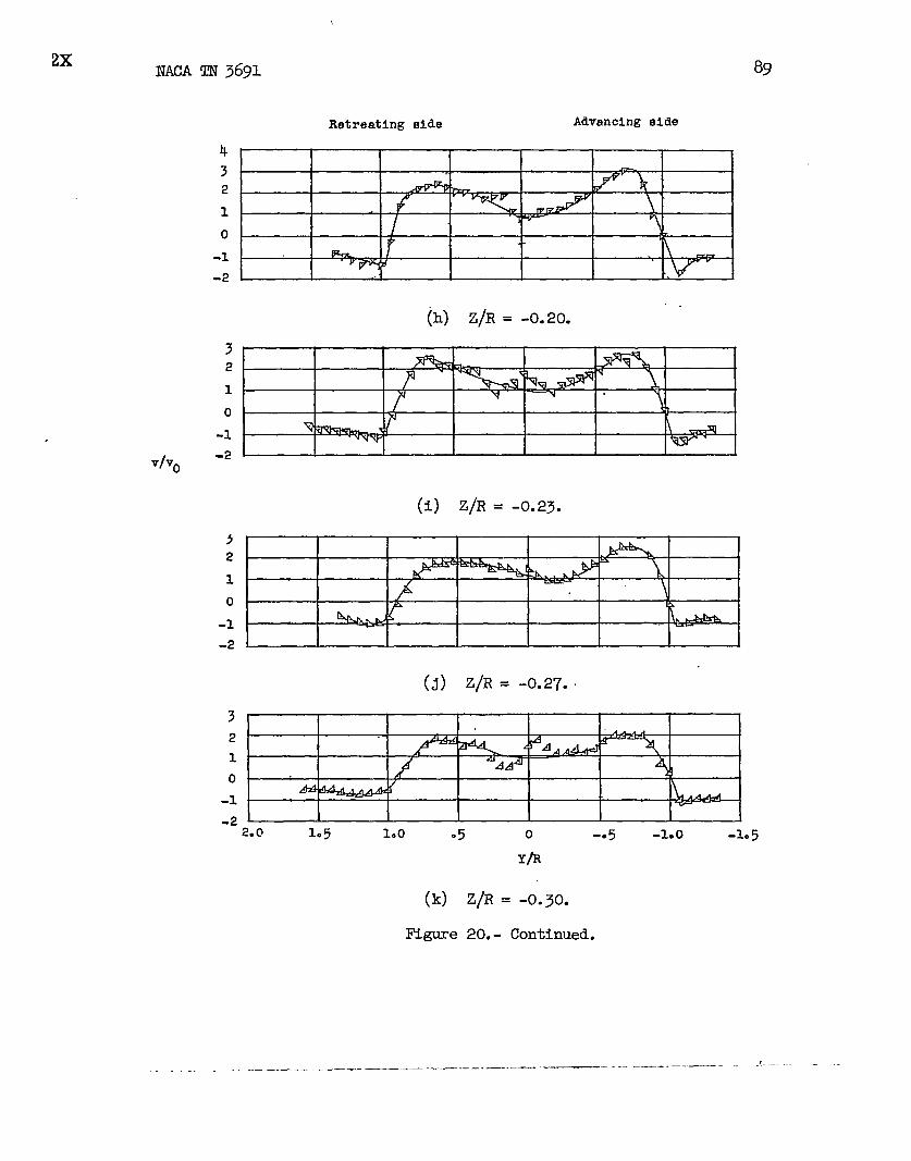
20.- Continued.
-_ —.—.. ..- —.. ——— — —--— -—— -— —--- ——

90 NACATN3691
v/v.
3210
-1-2
Advanoingaide Retreatingal~e
(1) Z/R= -O.33.
3-210-1-2
(m) Z/R=-0.37.21 — ~o
-1.
(n) z/R= -o.40.2
10 /
-1200 1.5 1.0 ●5 o -. 5 -1.0 -1.5
(o)
IRQure
Y/R
Z/R= -0.47.
20.- Cont3nued.
.
.
.
.

NACAIIN3691 91
v/v.
Advanoingside Retreating~ide
(P) z/R= -o.53.
21 I I I I I 11“ ‘
I
o“-1 J I I I I I I
(q) z/R= -o.60.2
1’0
-1 ~
(r) z/R= -o.67.
2
1
0
.1
(s) Z/R= -O.~.
21 1
-1105 1.0
(t)
Figure
o -05 -1.0 -1.5Y/R
Z/R= -0.80.
20.- Concluded.
—- . ...—-. .—.. —___ ...— ..- . . -—.——..—___ ___ ----

.
klvanolng aide rietretitlngaid-e
NACATN3691
32 I
10
-1-2
32
10
-1-2
-3
(a) Z/R= 0.07.
.
.
.
.
v/Y.
(b) Z/R= O..- .-
4 ,
32
10
0 /
-2 4
-3
(c) Z/R= -0.07.k32 — —
1 \o /
& ~ i-1 /
-2 I
-3;.0 1.5 l.c! ●5 o -.5 -1.0 -1.~
Y/R
(d) Z/R= -0.13.
valuesofinduced-velocityratio v/vo. X/R= 2. 07;x = 82.3°; u = 0.140. -
.
—.——

93
Advanalng side Retreating olde
.
3210
-1-2-3
(e) Z/R= -O.20.
>.
2 — —1 b-.o \●
-1v/v. -2
(f) z/R= -o.27.32 m a. 41 ‘ 4
1. fo \
-1 “Q@+@&%!&-2
(g) Z/R= -O.33.
2 ~10 \:
-l_ w- W
-22.0 1.5 1.0 .5 ,0 -. 5 -1.0 -105
Yh
(h) Z/R= -O.37..~gure 21.- Contin-d.
. ..-. ..——— .—.,_ .. ——-—___ ___ ____ ._. —— .. . . .
MACATM3691
Advancing8id0 Retreatingelde
3“2 — — sl
v1 \o-1--= ~ ~ — — —.-2“ .
(i) Z/R= -O.40.
3’2’10 Y
-1v/v. -2
(j) Z/R= -O.43.210
-1 M~ ~
(k) Z/R= -0.47.2
1
0-1‘-2.0 1.5 1.0
(1)
IZIgure
o -05 -1.0 -105
Y/R
Z/R= -0.50.
2Z.- Continued.
.
.
.
95
Advancingaide Retreatingaide
2
1
0-1
(m) Z/R= -O.53.
2
0 --1,
(n) Z/R= -O.57.
v/v.
2
1
0-1
(0) z/R= -o.63.2
1 ...........
0
-12.0 1.5 100 05 0 -05 -100 -1:5
(P)
Figure
“Y/R
Z/R= -0.70.
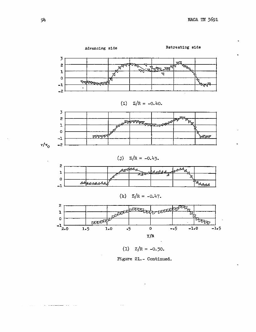
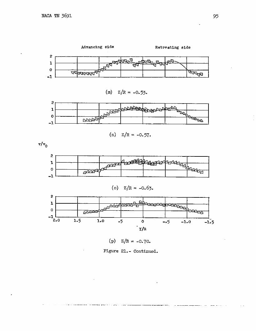
Z1..- Continued.
— —— .. —.. — —— —.. .. —._ _—_. .— —––.

96 NACATN3691
+..
“Advanolngaide Retreatingside
2
1
0
-1
(q) Z/R= -0.77.
2 ‘
o -~ . ---- --1
(r) Z/R= -0.83.
.1 ‘o
-1
10
(S) Z/R= -O.90. ~
-1__1*S 1.0 OS o -e5 -1.0 -1.5
. Y/R
.
.
(t) Z/R= -O.97.
Figure~.- Concl@ed.
—.—
.
13XNACATN3691
Advancingelse Retreating aide
.
3210’-1 I-2I t I I I I I I
(a) Z/R= O.03.
3 72 n
+* * * x. ..
,1 .. .. ... ....0 #
A-1 .,-2*
v/v.
(b) Z/’R=-O.O3.
43210-1-2
(c) Z/R= -O.10.
432 /k=
\1 / * Lo 4 A k
-1~-2
~fjj
-32.01.5 1.0 .5 0 -.5 -1.0 -1.5
Y/R
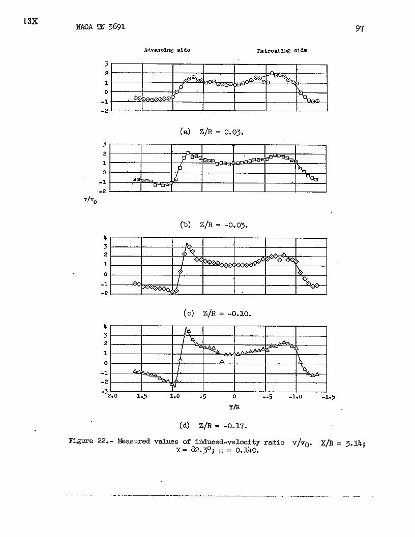
(d) Z/R= -O.17.
Figure22.- l%smredvaluesoffiduced-velocityratio v/vo. X@ = 3.14;x= 82.3°;I.I= 0.140.
..-. ..—_-——__ .- —-. ——- .—.——

.
MACAm 3691
Ahandng ei.de Retreating aide
k3210-1-2-3
(e) z/R= -o.23.3210 II L
-1 %2-2
(f) z/R= -o.30.
vho
321o-1-2-
(g) z/R= -O.37.
-z2*o 1.5 l.@
(h)
Figure
.5 0 -. 5 -1.0 -1*5
Y/R
Z/R= -0.40.
22.- Continued.
.
.
.
.
.

MAC!Am3691 99
Advanolngside Retreatingaide
3“2
10-1 .%-2
32
10-1-2
(i) Z/R= -O.k5.
(J) z/R= -O.47.v/v.
3“21’0“-1-2
(k) Z/R= -O.50.
3210-1
‘2.0 1.5 1.0
(1)
lRL~”e
OS o -05 -Lo -1.5
Y/Fl
Z/R= -0.~.
22.- Continued.
.. .— ..—. .— .-. —-———. . .—. — _ —

lco
Advanolngaide Retreating
NACAIm 3691
eide
321
,.0-1
(m) Z/R= -0.57.
321
0-1
(n) Z/R= -0.60.
v/v.
321o-1
(0) z/R= -o.67.2
10
-12.0 1.5 100 ●5 o -0
.
.
.
Y/R
(P) Z/R= -O.73.
ll~e 22.- Continued.
.

“NACATN3691 101
Adv~cingf3ide Retreatingside
2
1
-1
(q) Z/R= -0.80.21“— —o’
-1 ‘
(r) Z/R= -0.87.Vlvo
.
(S) Z/R= -O.93.5L1 . . . .
0. * 7@@--1 L“1*5 100 05 0 -*5 -1.0 -1.5
(t) Z/R= -1.00.
Figure22.- Concluded.
—....———— ~ ....—. .

NACATN3691
Mvanolng elde RetreatiMeide
Vfvo
2
0
-2
2
0
(a)z/Bm O.*.
.2=(c)Zhl= 0.=.
:=(d)Z/B.0.16.
2
0w% F
-2
1.0 .5 0 -.5 -1.0Y/R
(h) ZfiE -0.26.
I!lgure23.- Msasuredvaluesofinduced-veloci~ratiox= 83.90; p = 0.232.
.
v/vo. X/R= -1.O;

NACATN3691
Y/v.
Eigure24.-
.
Advanolng aide Retreat- Bide
2
0
-2 (8)Z/R- O.m.2
-2{b) Z/17-0.-
2.
00
v-W
-E(c) Z/R= 0.24.
2
0
-2. (d)Z/R-0.17.
2
0
-2(e) Z/RE -0.07.
2
0
-e(f) Zfil--0.14.
2
0
-e
2(g)z/R- -0.2L
o
-21.5 -1.0 -1.5
Measured
100
valuesx
.5 0 -.5.YIR
(h) Z/R.-0.27.
ofinduced-veticity= 83.90; p = 0.232.
ratio v/VO. X/R= -0.5;
.— _.. _ . .. .. —— -—— — —-— ——

1C!4
Mvamlng Bide
NACATN3691
RetreatingEdde
Vfvo
Figure25.-
2
0
-2(a) z/R-0.40.
2.
0-n
-2..(%)z/R- o.~ ‘
2
0
-2
2
0
-2
(c)2/%-’0.26.
(d)Z/Rm 0.19. .
(g)z/R.-0.2.L2
0
.‘i.5 1.0 .5 0 -.5 -1.0 -1.5
Yin(h) Z/RE -0.28.
.
.,
Msasuredvaluesofinduced-velocityratio v/vo. X/R= O;x= 83.90;w = 0.232.
.
.
___— —.—

NACATM3691
Mvanw aide netraat~ nide
Figure26.-
2
0
-2(8)Z@ .0.59.
2@n
o❑ /
-2 (b)Z~ = O.R.2
0z ‘
-2 - i(c) 2/2. 0.26.. . .
c I i I I i I2
0A
-eL I I I I I I(d) Z@ :0.19.
I 1 I I I I4 &
2 \ %%7
o
-2
-$WI
(* z/R- 4.07.I I I I I I
.?
<0
-2(2)z/R- -0.2L
2
0m +
v
-2-1.5 1.0 .5 0 -.5 -1.0 -1.5
Measuredvaluesofinduced-velocityratiox = 83.90;p = 0.232.
v/vo. X/R o.5;
-.— --- -- ----~—- ---— — —- .~————— —— .-—y--- _ .——

(a) Z/R= 0.21.
i 10 34-2
(b) Z/R= 0.14.
.(c) Z/R= O.C&
4
2 A0-e-8 ~.
(d) Z/R= 0.01.
m
(e) Z/R= -0.6.
Iltgure27.- Wasuredvaluesof bduced velocityratio v/vo. X/R = l.~;x = 83.9°; P = 0.232.
.

107
(f) Z/R= -O.12.
(g) z/R= -o.19.
Vvo 20-e
(h) Z/R= -0.26.
2 m-%.+@=@0-1
(i) z/R= -o.32.b
a I
o
-1
(3) m=-o”39”,z
0~
-3.5 1.0 .5 0 -5 .-1.0 -M
(k)
lZ1.gure
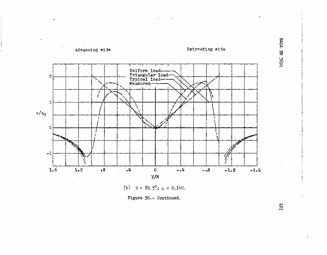
rh
Z/R= -0.46.
27.- Concluded.
— .— .-. —.—.——. — .—— —. —— ——-- — ——... — —.— ————-.— -._———

.
m TN 3691
Mgure28.-
(a) Z/R= 0.08.
2
0
-?
(b) Z/R= 0.01.
2t
a
4 1. 1 I I I 1
(c) Z/R= -0.0~.
(d) Z/R= -0.W.*
2
0 i 4i-e-A‘-2
-B r-1.5 2.0 .5 0 -5 -Lo -2-5m
(e) Z/R= -0.19.
valuesofinduced-velocityx= 83.9°;u = 0.232.
ratio v/vo. x/R= 2.07;
.
,
— .—— ————

log. .
AATmmlngnib
.
4b
E >
bo t
-2
(f) Z/R= -0.2s.
e
o /’-2
(g) Z/R= -0.32.
(h) Z/R= -0.39.2
0
-2
(i) Z/R= -0.45.
(J) Z/R= -0.52.2
0
-2I-5 Lo .5 -1.0
JR -“5-1.5
. (k) Z/R= ~0.~.
.— -.. —.—. ..—. — —.-. —.. — ~.— ..- ——— ————-.—. .-— —-

llo
VIro
Measured
(a) Z/R= 0.03... .—. ..-—
2
0
(b) Z/R= -0.03.
(c) Z/R= -0.10.4, 1 , I o
“I—r—H—t(d) Z/R= -o.17.
.
2
0 lb - “ -
-2 v
1.5 Lo .5 0 -.5 -Lo -1.5
valuesx
rln
(e) Z/R= -0’.23.
ofinduced-velocity= 83.90;u = 0.232.
ratio v/vo. X/R= 3.14;
.
●

NACATN3691
(f) Z/R= -0.30.
(g) z/R= -0.37.
(h) Z/R= -0.43.
(i) Z/I?= -0.50.
(3) @ = -0.57.20 d+’- fl % i.-%.5 Lo .5 0 -5 -1.0 -l-s
(k) Z/R= -0.63.
Figure 29.- Concluded.

.
112
.4
d?
E-.
-. 4
.4
n92
,/
o \
o ‘\ A1-imsul@r -
-.a w1’4x\
-04-*E -.4 0
v/v.
(a) X/R= -1.0.
. .0 .4 .8 1.2 1-.6
v/vo
(c) X/R=O.
-.2
-04
NACATN3691
.
0 .4 .8 1=
7/70
(b) X/R= -0.5.
(d) X/R= 0.5.
Figure30.- Comparisonofmeasuredandtheoreticalvaluesofvelocityratio v/v. inlongitudinalplaneofsymmetry.P = 0.095.
1.8 1.6
induced-X = 75.O“j

I
I
+0
(e) X/R = 1.07.
*
o
-.s
VI..4
-.0
.@
4.0
0 .4 ,# lJ 1,6 1,0
(f) X/R = 2.07.
Figure30.- bnchdefi
a
o
..s
I/I-.4
..i
-.*
4,0
8.4.sl.l Ll La
(g) X/R= 3.14.

Z/R
.2
c-* 4 0
v/v.
(a) X/R M -0.95.
94
Z/R
.i?
o
-0 4 0 04 0 .4 .0
v/v. v/v.
(b) X/R = -0.8. (C) X/R = -0.6.
0 .4 .8
v/v.
(d) X/R = -0.4.
Figure31.- Comparisonofmeasuredandlongitudiulplaneof
.4
0
\
\ ‘., Cl
i
\ )\\
1 [1 1 I I
1.2 0 .4 .9 1.2
v/v.
(e) X/Ii=-0.2.E!*
Etkoretical values of itiuced-velocityratio v/vO inSy-luuletry.x= 85.8°; p = 0.139. $
NAC!ATN3691 115
.
.
.
z/R
.4
Z/R.2
0
II I
–Unl~ormload3& -Trian~lu loedc) -TypiCd load
–Measured@ /{o
P/ ‘
/o ●4 .8
v/v.
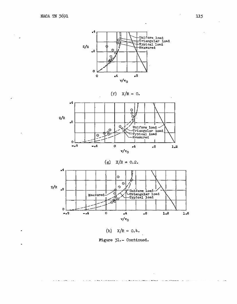
(f) X/R= O.
o -J--+-----rI I-0 8 -o 4 0 .4 08 1.2
v/v.
(g) X/R= 0.2.
0 , , ,-*9 -*4 0 .4 08 1.2 1.6
v/v.
(h) X/R= 0.4.
[email protected] Continued.
—..— .-— ..-— . .. . ..——....Z .——. —— .—.—————— .— —— ————— -—...-—. –.—

116 NACATN3691
, ,
0-o4 0 .4 .8 1.2 1.6
V&
(i) X/R= 0.6..4
o
I “
\
1 0/
.uniformload-----Triangnhr lcmd<Typicalloa~?deasured,
.,
.
0 .4 .8 1.2 1.6 2.0
v/v.
(j) X/R= 0.8.
.4? \\y,> ~
uniform loadTriangular10KI5 (3
Z/R .2 Typioalloati Cl \Measured o
6)~ \I
,/o0 .4 .8 1*2 1.6 2.0 2.4
v/v.
(k) X/R= 0.95.
Figure31.- Concludd.
—.. - —.—— —--

NACATN3691 117
04
a
Z/%
o
-J?
- .*
.4
B.,i’.2/
*Onlforml-d
SIlwlarM/’ lad l-d
●uul-eao
x.
-.s \
-e4--a -.4 0
+.
(a) X/R= -1.0.
o .4 .0 u
T/v.
(c) X/R’= O.
●
.4
-. e
-.4
4
.s
Z/E
o
-.s
-. 4o 04 .8 la
vho
(b) X/R= -0.5.
I I I I I I1 I I i I I I I i I I I I-. 4 0 .4 .e 1= 1.6
v/v.
(a) X/R= O.~.
Figure32.- Comparisonofmeasuredandtheoreticalvaluesof induced-velocityratio v/vO inlongitudinalplaneof synmetry.x = 82.3°;v = 0.140.
.
- --- .- -- .—.- ———-——-.——- --—- -—— —.. - —.—.-—.
E
‘i
0
*
-4
-,4
. . .
-’4
0.4.4t.i mm. ou
+0
(e) X/R= 1.07.
a
o
* -A
-.4
-A
.4
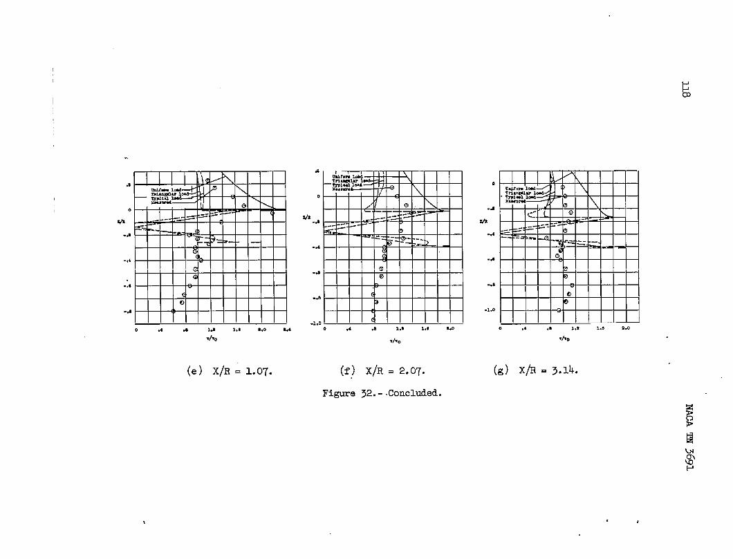
.1.00.4.81,s 1.*W
v%
(f) X/R = 2.07.
Figure32.-.Concluded.
4
-a
*
-.4
-.4
-4
.1.0
0 ,, ., ,,1 l.n 0.0
(g) x/’R=3.l4.
g’
.

NACATN 3691 llg
.
.
.
.4
.s
o
-a
-.4-. e -.4 0
T/T.
(a) X/R= -1.0.
0 .4 .0 1.2
v/r.
(b) X/h= -O.5.
04 4
.4 a
@@
o 0
-0s -.2
-.40
-.4.4 .e 1.s -.8 -.4 0 .4 .8 1s 1.6
T/v. T/v.
(c) X/R=O. (d) X/R= O.5.
Figure33.-Comparisonofmeasuredandtheoreticalvaluesof induced-velocityratiov/vO inlongitudinalplaneof symmetry.x = 83.903IJ= 0.232.
.
. .— . ..-—.——. . . . . . .—— - ———— —-—— —-— . .— .. —-—-

120 IIMAm 3691
a
-.4
0 .4 ..9 1.9 l.s S.o %4
./v.
(e) X/R= l.07.
o
-a
m-.4
-. 6
0
-a
*
-.4
-.6
0 .4 .s 1.2 1.8 a.o
+0
(f) X/R=2.07.
o .4 .e La 1.6 2.0
+0
(g) X/R=.3.14.
Figure33.- Concluded.

[
1
i
(a) X = 75.00;u = 0.095.
Figure34.- Comparisonofmeasuredandtheoreticalvaluasof induced-Velocitymtio v/vo alonglongitudinalcenterline.
I
t
I

Ii3
2
1
0
-1-1,0 -.9 -.6 -.4 -.2 0 .2 .4 ●6 .8 1.0
X/R
(b) X = 85. %J v = 0.139.
Fe ~.- Continued.
!=/

s
a
v/v.
1
0
-1-1.2 -.8 -.4“0 04 .8 La 1.6 0.0 a.4 8.8 S&
x/R
(C) Y,m82.3°;p= O.140.
Figure34.- Continued.

T/v.
-1.8 -.8 -*4 o A“*O 19s 1.6 a.o 0.4 9.0 3,!?
a
(d) x=83.90;P=o.232.
Figure~. - Concluded.
*

Figure33.- Effectof tip-speedratioon di6tilbU%iOn of induced-velocityratio v/vO alonglongitwiinalcenterline.
/j
I

Ii
Vlvo
klVRIlO~ng fllcle Retreating side’
1.6 1.2 .13 .4 0 -04 -6 g -102 -L 6
Y/R
Figure36.- Comparisonof measuredandtheoreticalvaluesof induced-velocityratio v/vO alonglateralcenterllne.
iag’
%
-1
1.6 1*Z .8 ●4
(b) X-
R@re
0 -,4 -0 g -1. E -1.6Y@
82.3°; p = o.M.
36. - Continued.

2
1
v/v.
c
-1
fMVanoLng aide Retreating aide
106 1.2 .~ ●4 o -04 -*8 -102 -106
Y/R
(c) XEB3.90JM= O.232.
l?kure 35. - ConcludA.

I
I
v/v.
3
2
P.D.-I
1
1 I A-. ! I 4/1FFFl”‘“
/ I 1 ‘\l 1fdo
/ I “\ \\L
/’—
I
-1.2 -1..0 -.8 -.6 -.4 -.2 0 .2 .4 .6 .8 1*O 1.2
X/R
(a) x = 75.(P; ~ = 0.035.
Figure 37. - Ccsnp.mtsonof inemuredvaluesof induced-velocityratio v/vOme with theoryof reference4 tified. ‘Premure distributionsI sndsnd P.D. III.
.
on longitudinal center
III denotedby P.D.I

130
v/v.
—
NACATN3691
(b) X = 85.80;p = 0.139.
Figure37.- Continued.
.
/ ‘
3
/
20
,
P.D.I /Measure
() () /1 \ $
)>/ /
// \ () f
//
\o (-) .
// L /I/- \
\ (? /
4u \ /
) \. /~’.~ I
I
-1.2-1.0 -.8-.6 -.4 -.2 () .2 .4 .6 .8 1.0 1.2XIR

v/v.
3
2 ,?!
//
“P.D. I I
P.D. 111 /
1 Measured= ‘., /k
/ ~I
//
/f \( \I
o Ii/ / ‘r
/ /
)
\o ,/
r
i)
\\ _ /
-1I
1I
-1.2 -1.0 -.8 -.6 -.4 -.2 0 .2 ,4 .6 .8 1.0 1
x/R
I
.Ii
I
II
●2
(c) X= 82.3°j~= 0.140.
Ffgure37.- Continued.

3
2
v/v.
oI
I-1
I
(d) x= E3.9°;pscI.232. gF
Figure 37.- Concluded.
,

. . .—— —. . —— . ..— — .-. .—.- - . —. ...--. .——.— .— -—>- . . .. ..- —. –.—. – .
NACATN3691 133
/ --7
/h/PeDeIJPJla 111> /
/ /
/ //— \ 9
\ ; /./
/,Y/R= -.25 \ _/ ●
y/R= +.25>
-e 4 0X\R
(a) x= 75.0°;w = 0.095.
04 ●tl
~gure 38.- Campsrisonofmeasuredvaluesofinduced-velocityratio v/v.at Y/R= &l.25”withtheoryof’reference4 modified.Pressuredistri-butionsI and111sredenotedbyP.D.I andP.D.III.

——— .—.
134 NACATN3691
3
2
1
v/v.
o
-1
0.
/ ‘/
/
//
I
/
/
-o 6 -o 4 o“ .k .8X/R
(b) x = 82.3°; ~ = 0.140.
lttgme 38.- Continued.
.

1.35
.
3
2
1
VIVO
o
-1
P.Do 1~
-o4’X/R
(C) X= 83.9°;p= 0.232.
Mgure 38.- concIuded. .
.

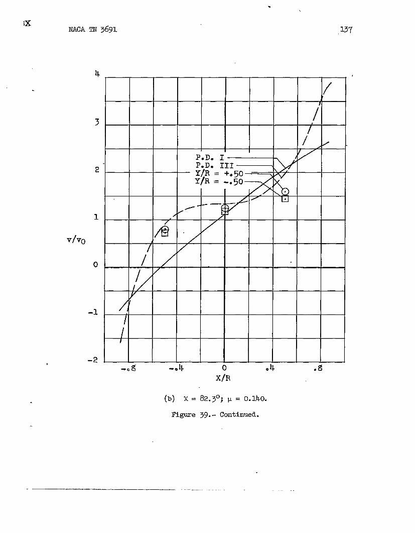
136 NACA!rN3691
;/v.
IRlgureat
3
2
1
0
–1
-2
/\
1/
P.Do I /P.D. III=I
Y\R = +050 t’b~‘-
Y\R = ‘o~t)
/“
/‘1/
I
/
/
//
/
I
/
I
-o 8 -04 0 .4 .8x~
(a) X = 75.0°; p = 0.095.
39*-Comparisonofmes&uredvaluesofinduced-velocityratiov/v.Y/R= ~.~ withtheoryofreference4 modified.Pressuretistri- -
butionsI andIIIdenotedbyP.D.I andP.D.IIZ.
.
. . . . —.-.. . - .— ——— —-—— ..—..— ._ .—.— —.
.
iXNACATN3691
4
3
2
1
v/v(J
o
-1
-2
/
/
P.D. IP.D. IIIY/R= -t.50Y/R= -.50
\-.—
/ ‘/
/
E
/
/
{
/
/I
-0 ~ -04
(b) X =
Figure
82.3°; ~= 0.140.
39.- Continued.
137
.
-.

138 NACATN3691
4
3
2
1
v/vo
o
/
I/
P.D. IP .D. III \\ / ,Y/R = +. ~0Y/R = -o ~01
@ /_—// /
/0 [11/
/
tI
I
-08 -.4’ 0 *4 .8X/R
(c) x = 83.9°; ~ = 0.232.
Figure 39.- Concluded.

—.. ———— .—. .. . . ... .—._ ...— ——— .— —.. —.. A . .. ——. .— ..—
NACATN3691
3
2
v/v.
Q
.
M.gure40.-at Y/R=>butionsI
[
/4r (
//
I P.Do I /tP*D. 111~I
/ /
#
I//
-0 $
(a)
Comparisonof*.75 withandIIZare
i
(
lL-0 . 0
139
l@R
x = 75.00;p = 0.095.
measuredvaluesofinduced-velocityratio v/v.theoryofreference4 modified.Pressuredistri-IenotedbyP.D.I andP.D.III.
—.——

. ..—.— — _——
140 MACATN3691
5
3
2
1
v/vo
o
-1
-2-
(b) x = 82.3°; p = o.1110.
figure 40.- Continued..

— ..—.. ——— ——— —_______ .— .. —-.._ ...-. —- . .. ——.— . . .— .
.
.
.
NACATN3691 M
5 - r/I
/f
4 . /
I/
. / El,
/
P.D.IP.D.111
2 Y/R =- ●75Y/R=+*75
1
vlv~
o
-1
-2
(c) x = 83.9°; ~ = 0.232.
HgurekO.- Concluded.
——.— .. .—. — ——.-——

Advancing i3iae Retreating aide
1
v/v.
o
-1
I I II .. \
/ \ \\\
p \
‘peD. I‘P.D. III- .
L 0\
-Meaaured
1
T
L I I
102
Figure41.- Conmmisontheoryof referenceandP.D.III.
, ,
I I I I I I I I I
-0 8! -1●8 - .4 0 k-0 .Y/R
(4 X= 75.0°; I-L=0.095.
of measuredvaluesof induced-Velocityratio4 miified. pressuredi.atributionaI and III
,a 2I
v/v. at X/R= -0.5 withexe denotedby P.D. I

. .
I
I I
I1
v/vo
o
-1
-2
Advanalnge~de Retreatinge~de
PoD. I \PoDo IIIMeasured \ \
\ \\
/\
{~
\//
\ \\\~
i‘ k
\
1 1 I 1 I 1 I I I1.2” .~ ●4 o -0 4 . -.$ -1.2
X/R
(b) x=82.3°;IL=0.140.
Figure 41. - Cmtinued.
I

Advancingside Retreating Bide E
0 -* k -0 8 -102
(c) x=
F5.gure
Y/R E*
83.9°;p = 0.232. =w
41.- Concluded. $
r

II
IJI
2
1
v/v.
o
-1
1
Advmclng side Retreating aide
1 1
P. D, I‘P, D, III&eaeured
/-A
.
k 1/f// !
// \,
./A’‘ II
\‘1 ‘J
.4 0 L1. -.8-0 -1
u$’
*2
Y/R
(a) x=75.0°; ~= 0.035.
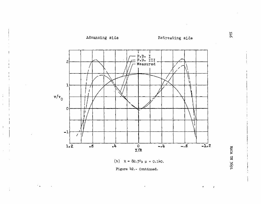
Figure k2. - Comparisonof measuredvalueBof inducedvelocityratio v/vn on laterelcenterllne &tith theoryof reference4 modified. Wssure distributionsI and 11~ me denotedbyP.D. I GandP.D. In.
Advanoing siLe Retreating side
‘1
i
I
2
1
v/v.
o
-1
1*2 .8 04 0 -0 4 -. E! -102Y/R
(b) X=82.3°} y= O.lkO.
Figure42.- Continued.
1 r

‘.
2
1
v/v.
o
-1
Advanolngaltie Retreating aide
I
1.2 -0 4
(c) x=83.9°jLL=o.232.
Figme 42.- Concluded.
-0 f3 -102

. ———
NACAm3691
Advsnclngside Retreatingside
-1●“2
I?igure43.-
*4 11-0 . -0 g -1* 2
(a) X= 75.0°; p = 0.095.
Compatdsonofmeasuredvsluesofinduced-velocityratio v/v.at ~/R = 0.5 withtheoryofreference%utionsI andIIIdenotedby P.D.I and
4 mcdified.Pressuredistii-P.D.IU.
.

.—.. —=. ——.. . . .... — .- ..4._. ___ .. ... -. .-L- ___ _ ..— ——. -._—— .-
-.
.
NACATN3691
Admmlng alde Retreatingside
(b) X=
l?Lgure
.4 0 -0~ . -Oe -102Y/R
82.3°; p = 0.140.
43.- Continued.

..
——— -—. -
150 NACA~ 3691
4
3
2
1
v/vo o
-1
-2
-3
1
Advancingeide Retreatingaide
8 r/ 1 / )/ I
\ /, \
\\II ‘/
I
\ — ~ f I
I/< / P.D.1A IN
I / \ \P.D.ZII LMeasured~ If/
1II ‘qJ, /~
II
v1
\I \ \ //
\“\///
II
I ,
-\\ \ ,/A/
I I
\‘, ‘
1I
II I
,*2 ●g 06 0 -*4 -0 ~ -1.2
Y\R
(c) x=83.9°; ~=o.232.
Figure43.- Concluded.

. . . . . .. ..— —— ——. — . ---- . ——- —- .-— -- . ---- -..—------ ——--———--- —---- .- —.. —.. .,—
Figure
at
IJ=
151
-Oing #ids Bstrmtlng●lti.5
0
*
-. 5
-Lo~5 1.0 .5 0 -5 -Lo -1.5
m
(a)Measureddata.
.5
0
m
-.5
-Lo‘1.5 Lo .5 0 -5 -Lo 4.5
lb
(b)Theoretical,pressuredistributionI.
.5
0
*
-5
-Lo“1.5 Lo .5 0 -. 5 -Lo -L5
IIR
(c)TheoreticsJ.,pressuredistributionIII.
~. - Comparisonofmeasuredvaluesofinduced-veloci’qyratio v/voX/R= 2.07withtheoryofreference4 modified.X = 75.0°;0.095.
152
.5
0
*
-,5
-Lo
.5
0
m
-+5
-Lo
‘hauolw S149
I I
——
NACATN3691
Iutrmt”bgSia,
L5 Lo .5 0 -.5 -Lo -1.5m
(a)Measureddata.
-
Fx I/’rzL&l’\IK:*41--- I 1I ho \
-d
/
1.5 Lo .5 0 -.5 -Lo -1.5rh
(b)Theoretical,pressuredistributionI.
U Lo .5 0 -.5 -Lo -L5m
(c)Theoretical,pressuredistributionIII.
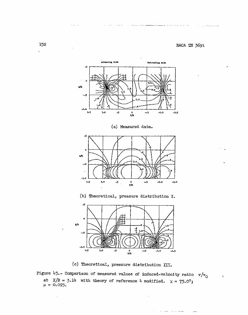
45.- Comparisonofmeasuredvaluesd induced-velocityratio v/vO
X/R= 3.14 withtheoryofreferenceh modified.X= 75.0°;0.095.
.
—

_—. -—— .. ——— ——..-. — .— ---—— .-— .. . .. ..-—. . . ..-. .-—- —.-.———
.
Figure
atP =
.5
0
*
-.5
-1.0
.5
-1.0
153
1.5 Lo .5 0 -.5 -Lo -1.5X/a
(a)Measureddata.
-..1.5 Lo .5 0 -.5 -LO -L5
rta
(b)Theoretical,pressuredistributionI.
.5
0
*
-. 5
-Lo105 Lo .5 -.5 -Lo -L5
$
(c)Theoretical,pressuredistributionIII.
46.- Comparisonofmeasuredvaluesofinduced-velocityratio v/vOX/R= 2.07 withtheoryofreference4 modified.X = 82.3°30.140.

___—
NACATN3691
.5
-Lo
.5
Qm
-.5
-Lo
(a)Measmeddata.
(b)Theoretical-,press~e~strfbutfonI.
(c)Theoretical,press~e ~s~fbutfon ~=
Figure47.- Comparisonofmeasuredvaluesofinduced-veloci~ratio v/v.at X/R= 3.14 withtheoryofreference4 modified.x= 82.3°;P = 0.140.
,.
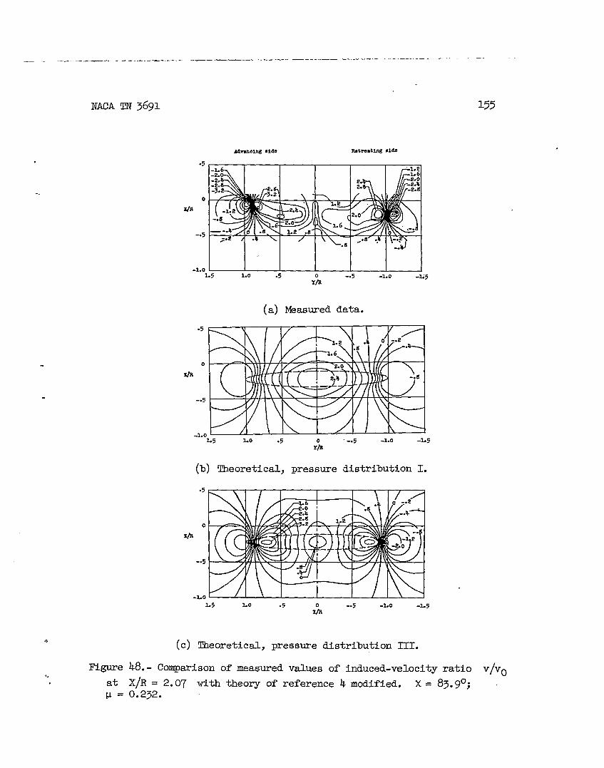
— ______ __ . . ... . . .... —_— —.— —.— — ...— .— .-. ..—. —.—, —
NACATN3691
-.
.5
0
Z/B
-.5
-1.0I I I I I I I1.5 Lo .5 -1.0 -M5
rob ‘“5
(a)Bkasureddata.
.5
0 I / !\\\II A
c,-..
L5 Lo .5 0 .-.5 -LO -L5Yb
(b)Theoretical,pressuredistributionI.
.5
-LoL5 Lo .5 -5 -Lo -1.5
1%
(c)Theoretical,pressuredistributionIII.
155
Hgure 48.- Comparisonofmeasuredvaluesofinduced-velocityratio v/vOat X/R= 2.07 withtheoryofreference4 modified.x = 83.9°;P = 0.232.

156
————
NACATN3691
MmolngSlti E@l-uux●ids
(a) Measureddata.
.5
0-
-. 5
-LO~5 Lo .5 0 -5 -Lo -1.5
TIP.
(b)Theoretical,pressuredistributionI.
.5
0*
-5
-1.0I / /1 \ I I t
1.5 Lo .5 -.5 -Lo -1.5X“b
(c)Theoretical,Pressurefis~ibution1~0
IYgure49.- (hmparisonofmeasuredvaluesofinduced-veloci@ratio v/v. .’at X/R= 3.14withtheoryofreference4 modified.x= 83.9°;v = 0.232.
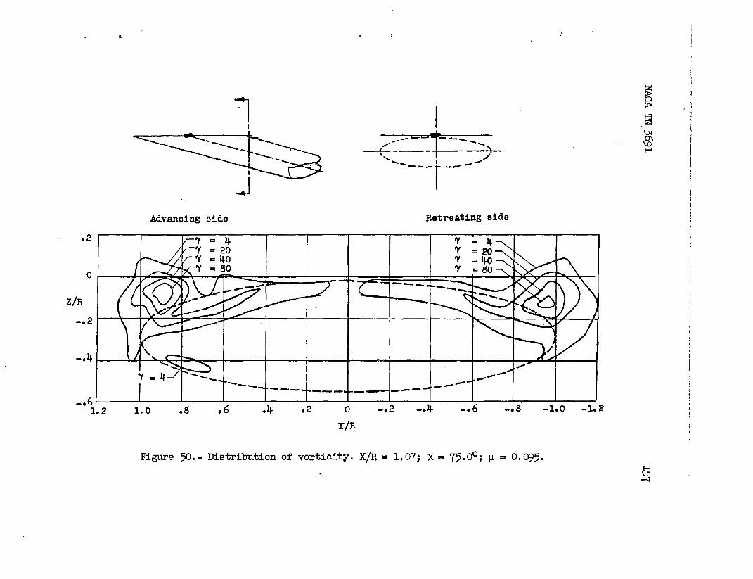
. ,
Advanoing side Retreating side
0
Z/R F-t---L-.2
-.4
6 [-“ 1.
= ifo I I I IA I I I
/11 I
- ---
Y/Ii
Figure ~.- Di.stributionof vorticlty,X/R = 1.07;X= 75.0°;v = 0.035.
IiI
I
t[
I1

.2
0
Z/R
-.2
1Y=‘t=7’=
-*4 ‘r =
,-. 6L
1
--=+”-Advanolng al&e Retreating 13i~
1.2 1.0 .s .6 .4 .2 0 -. 2 -*4 -. 6 -0 ~ -1.0 -1.2
Y/R
(a) X/R= l.O’7.
Figure51.- Dlstrfbutionof vorticitytmhindrotor.x = 82.3°;p = 0.140.
A
II
!2
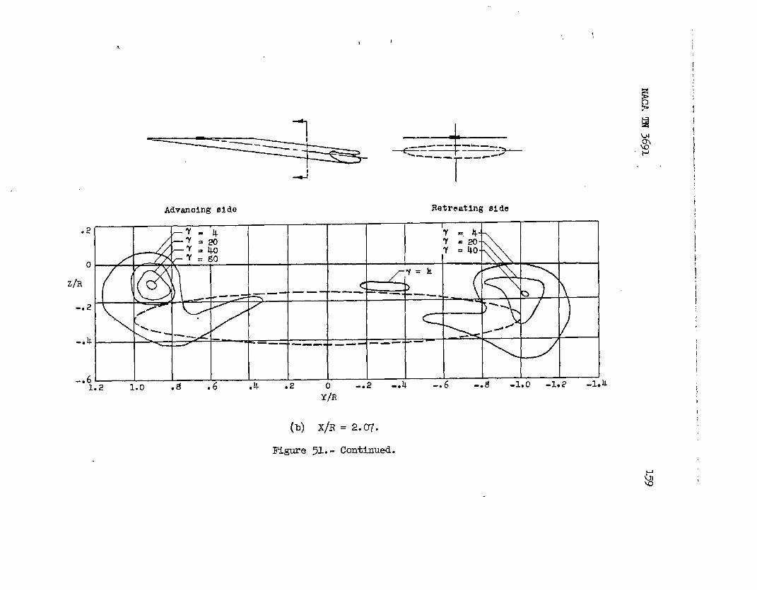
#I
1 I1 -L
+=.:-=: -====-2?-r-..
4 I
Advanaing side Retreating elde
.2 -’r -4 7 =, 4-~~=!?o ‘r .20--’f =40
/ ~’i7 = 40-
0 = go
zh
-.2,< //~
4-.
6‘“1.2 1.0 .8 .6 .4 .2 0 -.2 -.4 -.6 -.a -1.0 -1..? -1.L
I
iY/Ii!
(b) X/R = 2.07.
l?Qure51.- Continual.
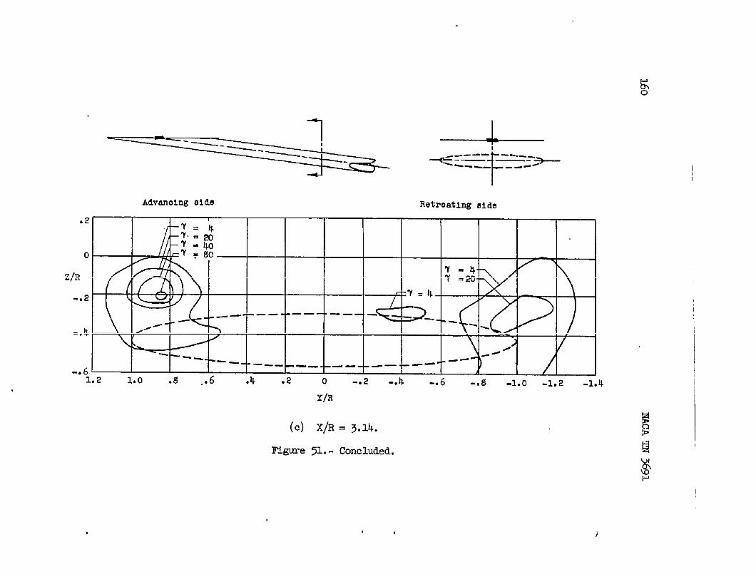
v----------.——.-+._.-..Advanolng aide RetreatingBide
.2
0
z/R
-.2
-. 4
-* 6
I
1 ?--7= 4./
- -- -—- —— —— —,/-/ Y
I “r--+---L--L--L-L-L-1.2 1.0 .8 ..6 .4 .2 0 -.2 -.4 -.
Y/R
(c) X/R = 3.14.
Rlgure>l.- Concluded.
7=4-7 =20-
.-
// J /---
}AI -. s -1.0 -1.2 -1.4
, J

1 I _&Ld
-’=+==-:+I
4 I
Adve.nolng side Retreating eicle
o1~< -!-= I I 1 \ I ~ i II
— — —
7 In I-/ .,
-. i? —— . “ _— -
-041.2 1.0 .g .6 .4
F@we ~. - Distributionof
.,2 0
Y/R
vorticity.XflR
-. 2 -04 -0 6 -c g -1.0 -1.2
= l.~j x = 83.9°;p = 0.232.
t
II
I
I
I
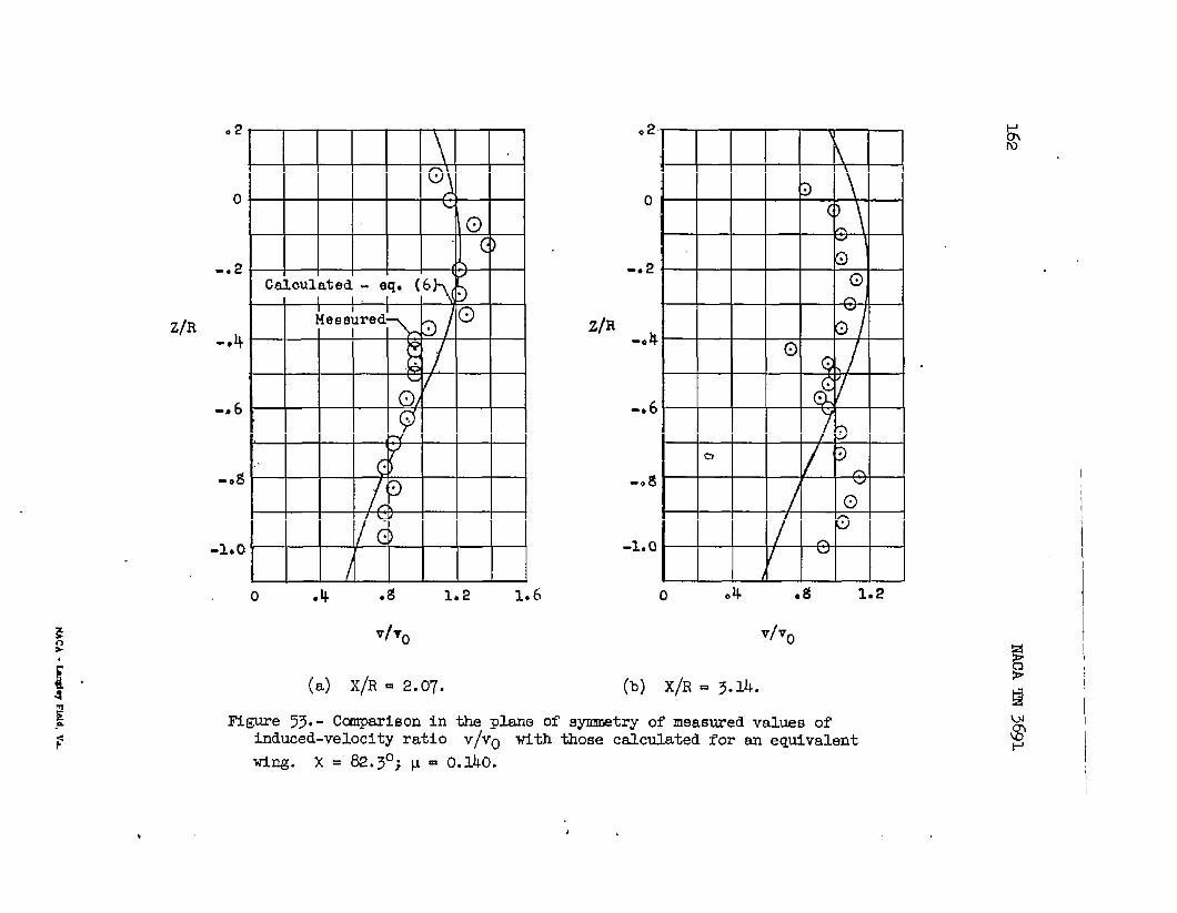
Z/R
,
.2
00 L
b-.2 (%
Cah3ulated-I I I
-. 4
b0/‘-s6
-0g “’
LvG)-1.0 1
/o .4 ●g 1.2 14
VITO
(a) X/R Q 2.07.
)6
z/R
(b) X/R E 3.14.
Figure73.- CcmparlSonin the phne of symmstryof measuredvaluesofinduced-velocityratio v/v. with thosecalculatedfor an equivalent
wing. x = 82.30; p = 0.140. I