nationaladvisorycommittee for aeronautics/67531/metadc56647/m2/1/high... ·...
TRANSCRIPT
.
.
NATIONALADVISORYCOMMITTEEFOR AERONAUTICS
TECHNICAL NOTE 4057
INVESTIGATION AT LOW SPEEDS OF DEFLECTORS AND SPOILERS AS
GUST ALLEVIATORS ON A MODEL OF THE BELL X-5 AIRPLANE
WITH 35° SWEPT WINGS AND ON A HIGH-ASPECT-RATIO
350 S~pT-~G_~SE~GE MODEL
By Delwin R. Croom and Jarrett K. Huffman
Langley Aeronautical LaboratoryLangley Field, Va.
Washington
June 1957

R
~g
NATIONAL ADICU30RYCOMMITTIZZIUR AERONAUTICS ~:g= “
TEC!IINICALNOTE k05~ rm 2fr~ q
INWZSTIGATION AT LOW SPEIZl)SOF DEFLECTORS MID S~IUZRS AS :~ ~- -m
GUST KIILIZWIATORSON A MODEL OF TID3MIU X-5 AIRpIM13 =!=%
WITH 35° m WINGS AND ON A HIGH-MWTCT-RATIO
35° ~-W~G—~EMGE MODEL
By Delwin R. Croan sd Jarrett K. Huffman
SU4MKRY
An investigation was made at low speeds in the Langley 3~ MPH 7-by 10-foot tunnel to determine the gust-alleviation capabilities (reduc-tion in lift-curve slope) of spoilers and deflectors on a high-aspect-ratio 35° swept-wing-fuselage mciielsnd a l/4-scale rncdelof the BellX-5 airplsme with 35° swept wings.
.l%e results indicate that deflector and spoiler-deflector types of
controls can be designed to provide considerable gust alleviation for a
eswept-wing airplane while still maintaining –
INIRODIK!TION
Results reported in reference 1 showedwhen mounted nesr the leading edge of the unswept wing of a transportmodel, were effective in reducing the normal acceleration due to gustsby reducing the lift-curve slope. It was anticipated that this type ofcontrol would be extended when rough air was encountered by a transportairplane and remain extended as long as the airplane rmained in roughair. The investigation has been efietied in this report to includesimilar devices on swept wings.
stability and control.
that spoilers and deflectors,
●
✎
A prelimtiary series of tests, referred to in reference 1, was madeon a wing with an aspect ratio of 8.35 and 34.P of sweep (referred tothe unswept-wing quarter-chord line). The results indicated that thedevices should be placed farther back on a swept wing than on the unsweptwing model of reference 1 and might require ventilation frcm the lowerto the upper wing surface. Several of the more effective configurationsfound in these preliminary tests were incorporated in the investigationof the high-aspect-ratio model and the l/4-scale model of the Bell X-s air-plane with the wings swept back 35°.
smLs
b
*
The resultscients of
CD
CD,b
CL
cm
cl
CLa,b
c&
b
%
c
E
cav
cA=Oo
~
s
it
x
(xdA*O
forces
drag
drag
lift
of the investigation are.presented as standard coeffi-and mcments about the wind axes.
coefficient, M3g/qs
coefficient of the basic model
coefficient, Lift/qs
pitching-mcment coefficient, referred to 0.255,Pitching moment
q%
rolling-mcment coefficient due to control
slope of lift curve of basic.model, per d.eg
slope of lift curve of model with deflectors or spoilers, .per deg
wing span, ft . —
deflector span, ft
wing chord parallel to free airstresm, ft
wing mean aerodynamic chord, ft
average stresmwise chord spanned by control, ft
wing chord measured perptiiculm to qusrter-chord line ofunswept wing, ft
dynemic pressure, lb/sq ft
wing axea, sq ft
horizontal-tail incidence, positive when trailing edge isdeflected down, deg ..
longitudinal distmce, ft ..
chordwise position of deflector measured perpendicular toquarter-chord line of unswept wing, ft
●

NACA Tti4057 3
.
~ inboard end of control, fraction of wing semispan* b/2
Yo outboard end of control, fraction of wing sedspam~
a angle of attack, deg
68 left aileron deflection, positive when trailing edge isdeflected downward, deg
6d deflector projection, negative direction away frcznchordplsne, fraction of wing chord
86 spoiler projection, negative direction away frcm chordplane, fraction of wing chord
MODELS AND APPARATUS
Two models were used in the present investigation, a l/4-scsle model●
of the EeU X-5 resesrch airplane having wings with 350 of sweep (referredto the unswept-wing quarter-chord line) and a wing-fuselage model having
. a wing with 34.93° of sweep (referred to the unswept-wing quarter-chordline). This wing-fuselage model had a taper ratio of 0.589, an aspectratio of 8.35, and NACA 65AO09 airfoil sections at an angle of 43.83°with the wing leading edge. It is hereinafter referred to as the high-aspect-ratio model. Drawings and physical characteristics of the m~elsare shown in figure 1. The high-aspect-ratio mcdel and the X-5 modelwere tested with various combinations of spoilers sad deflectors. Thevarious control spans, chordwise locations, and projections are givenin table I and figures l(b) and 2. Ventilation through the wing forthe spoiler-slot-deflectors and for the butterfly-valve arrangementson the X-5 mdel was accomplished by drilling 22 holes, 13/16 inch in
dismeter and spaced with centers 1* inch apart, along the 0.35cA+0 line
between 0.34b/2 and 0.~b/2. (See-fig. 2.) The butterfly-valve srr~e-ment consisted of circulsr disks that closed the holes in the neutralcondition smd when deflected 90° formed a scalloped spoiler with a projec-
1
tion of ~ percent on the upper surface of the wing. Ventilation through
the wing for the spoiler-slot-deflector on the high-aspect-ratio mciielwas accomplished by means of a O.O~cAao slot along the 0.143cA@o,
.0.386cA+0, and 0.637cA+0 lines betweenO.2gb/2 and 0.49b/2. (See
fig. l(b).).

4 NACA TN 4057
!I’hestatic longitudinal and lateral aerodynamic chsract~isticsof the models were obtained on the single-strut support systm in theLangley 300 MPH 7- by 10-foot tunnel.
TESTS
The tests on the high-aspect-ratio model were made at a dynamicpressure of approximately 34.5 pounds per square foot, which correspondsto an airspeed of about 170 feet per second, and the tests on the X+model were made at a dynamic pressure of approxhuately 44.5 pounds pasquare foot, which corresponds to an airspeed of about 193 feet persecond. Reynolds number for these airspeeds, basti on the wing mean aero-
dynenic chords of the models, ~e approximately 0.$% X 106 and 1.89 x 10⁶for the high-aspect-ratio model and X-5 model, respectively. The variousconfigurations tested are listed in table 1.
CORRECTIONS\
The values for angle of attack snd drag have been corrected for jet- ●
boundary effects by the method of reference 2. The data have been cor-rected for tunnel ah-flaw misalinement, tumnel blockage, and longitudinal . -pressure grsdient in the
Smmary plots which
tunnel.—
RESULTS AND DISCUSSION
show the effect of chordwise location, projec-tion, smd span of the various spoiler and deflector configurations onthe gust-alleviation capabilities (reduction in lift-curve slope) arepresented in figures 3 to >. The solid symbols in these figures indi-cate that the variation of lift with angle of attack was nonlinear, asshown in the basic-data figures (figs. 6 to 25) from which these pointswere obtained.
The ratios of the lift-curve slopes of the mdels with controls tothe lift-curve slopes of the basic mcdels are presented in figure 3 asa function of the chordwise location of the controls for several controlconfigurations on the X-5 model and the high-aspect-ratio model. It iS
indicated in.figure 3 that these controls b6csme more effective inreducing the lift-curve slope as they were moved resrward to approxi- .matel.ythe 35-percent-chord line. The maximmn reduction was obtainedfor these models when the controls were located between the 25- end35-percent-chord lines. On the unswept-wing model of reference 1 the .
controls were located along the 12-percent-chord line and gave 20- to

NACA TN 4057 5
kO-percent reductions in lift-curve slope. The results of the presentinvestigation and that of reference 1 indicate that the controls shouldbe located fsrther back on a swept wing than on an unswept wing in orderto obtain the desired reduction in lift-curve slope.
The magnitudes of the reductions in lift-curve slope achieved withthe devices which extended fromO.34b/2 to 0.~b/2 are shown in fig-ure k(a), where the lift-curve-slope ratio is plotted against deflectorprojection for the several devices. The deflector alone gave reductionsup to about 35 percent.for a deflector projection of 15 percent of theWing chord. If more reduction than this is desired, ventilation throughthe wing is required. A spoiler-slot-deflectorwith a spoiler projection
of ~ percent of the wing chord (the optimm projection for this arrange-
ment) gives a reduction of about ~ percent for a 15-percent projectionof the deflector. Since the spoiler-slot-deflectorsappear to providemore reduction in lift-curve slope than the plain deflectors, two vari-ations of the spoiler of the basic spoiler-slot-deflectorwere studied.One was a spoiler that was sufficiently long to cover the holes and was
deflected to ~percent of the wing chord (hereafter in this report
referred to as the slant spoiler), and the other was a butterfly=valvearrangement. E!oththese arrangements provided Urger reductions in lift-curve slope than the basic spoiler-slot-deflector. When the deflectorwas projected 15 percent of the wing chord, the slant-spoiler arrangementreduced the lift-curve slope about 62 percent and the butterfly-valvearrangement reduced the lift-curve slope about 70 percmt, which was themsxinnm reduction attain~ for the 50-percent-span controls. (Seefig. 4(a).)
The plain-deflector, spoiler-slot-deflector, slant-spoiler, andbutterfly-valve arrangements were also tested with a shorter span(O.34b/2 to O.66b/2) and the results are smmar ized in figure k(b).The ssme general trends in lift-curve-slope reduction were noted forthe 32-percent-spsn controls (fig. h(b)) as for the ~-percent-span con-trols (fig. 4(a]). However, gaeraldy, the effectiveness of the controlwas not proportional to the span of the control.
Figures k(a) snd 4(b) also show the increase in drag resulting fr=the pro~ection of the devices. It can be seen that for ~ of the devicesthat give more than 20-percent reduction in lift-curve slope, the drag
(ratio at ~ = 0.3) is greater than 2, which indicates that any of these
devices should be god aerodyns.micbrakes and would aid in slowdown.
A deflector ad a butterfly-valve arrangement having several spanswere tested on the X-5 model to determine the effect of span of controlon lift-curve-slape reduction. These data are presented in figure 5.

6 NhcA m 4Q57
The inboard ends of these controls were at 0.34b/2 except for the18-percent-span controls, which began at 0.41b/2. It can be seen frcmthese data that when the deflector was located along the 35-percent-chord line the reduction in lift-curve slope did not decrease~ithdecreased span of control as rapidly as when the deflector was locatedalong the 25-percent-chord line. It may also be seen that for the35-percent-chord location the Mft curve was linear, whereas for the25-percent-chord location the lift curve was nonlinear.
I?igure6 shows the effect of spoiler projection on the linesrityof the lift curve of a typical spoiler-slot-deflectorarrangement onthe X-5 mdiel. In order to obtain linear or near linesx lift curvesthe correct ratio of spoiler projection to deflector projection must bedetermined for each installation. For the X+, figure 6 indicates that
8~ -o●025—=—8s -0.15
resulted in a linear lift curve. The effect, if any,
that nonlinear lift curves have on the gust-alleviation capabilities hasnot been determined.
The effect of ventilation from lower t~ upper surface on the liftcurve is shown in figure 7. As the ventilation is increased, at least--”up to the maximum used for these tests, the reduction in lift-curveslope becomes larger.
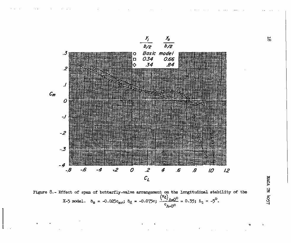
The longitudinal stability characteristics of the X-5 model with abutterfly-valve arrangement are presented in figure 8 for two spans. Itcan be seen that the control with the longer span had a destabilizingeffect on the pitching mxnent, whereas the control with the shorter spanwas more stable than the plain wing configuration up to a lift coefficientof 0.70. These results indicate the probl~ that mey be encountered withsome wings. The longitudinal aerodynamic characteristics of all the con-trol configurations sre presented in figures 9 to 27.
The effects of the devices on the lateral control characteristicsof the X-5 model are shown in figure 26, where the rolllng-mcment coeffi-cient due to +10° of aileron deflection is plotted against @e of attackfor the wing equipped with a butterfly-valve or a spoiler-slot-deflectorarrangement. The inboard end of the aileron was at 0.66b/2,~and when thedevices extended outbosrd of this point (frcm 0.34b/2 to 0.&lb/2), theaileron was ineffective in the low and mckierateangle-of-attack renge.However, when the devices were located entirely inboard of the aileron(from O.34b/2 to 0.66b/2), aileron control was maintained throughout themoderate single-of-attackrange and the aileron had more than w percent—of the effectiveness of the aileron on the plain-wing configuration.
Since these spoiler-slot-deflectordevices resemble a spoiler-slot-deflector type of aileron, a few tests were.made to evaluate such a
._
—
.
.
—.—
.
NllcAm 405’7
device for use as both an aileronpresented in figure 27. As shown
7
and a gust alleviator. lt!hesedata areby the sketches in figure 2’7,for the
condition with the gu&alleviation device retracted the l-es are soarrmged as to project the spoiler 15 percent and the deflector 5 percentof the wing chord to obtain lateral control. For the condition with the
gust-alleviation device extended the spoiler is projected ~percent ad
the deflector 10 percent, and to obtain lateral control the spoiler pro-jection is increased to 15 percent on the left wing. It canbe seenthat for both the retracted and extended conditions, for both spans ofthe controls (0.34b/2 to 0.66b/2 and 0.34b/2 to 0.84b/2), this ty-peoflateral-control device provided control as good as or better than that—of the conventional aileron for flO” deflection.
C!ONCLUDINGIUIMARM
‘I!heresults of sm investigationmade at low300 MPH 7- by 10-foot tunnel of a 35° swept-wing
speeds in the Langleymodel of high aspect
ratio sad a i/4-scale model of the E=ll.X-5 airplane having 350 sweptwings indicate that deflector smd spoiler-deflector t~es of controlscsn be designed to provide considerable gust alleviation (reduction inlift-curve slope) for a swept-wing airplane while still maintainingstability and control.
Langley Aeronautical.Laboratory,National Advisory Ccmmittee for Aeronauticsz
Lsmgley Field, Vs., April 22, 1957.
REFERENCES
1. Croan, Delwin R., Shufflebsrger, C. C., and Huffman, Jarrett K.: Antivestigation of Forwsrd-Located Fixed Spoilers and Deflectors asGust Alleviators on sm &swept-Wing Mcklel. NACA~3705, 1956.
. 2. Gillis, Clarence L., Polhsmus, lllwsrdC., and ~ray, Joseph L., Jr.:Chsrts for Determining Jet-I!o~sry Corrections for C!cmpleteModelsin 7- by 10-Foot Closed Rectangular Wind !l?unnels.NACA WR L-1.23,
. 1945. (FoITET2Y NACAARRL5G31.)

8 NACATN 4057.
T&m I.-TrFz,PR’mmmI, c222xcm sccmmn,4m2worm vmommmxaa
(.)Lm2ituMnnld8t8?- ml x-5a
1
Typ+or ccatrol % %, (4A*.VmaltC*V ml”==% CSV CMO % % 2 -’
Sff9ct of ckrdube lmaticm
~tm- -T.7 0Mfl.ectar
0,0.12,0.13,O.=, O.io4.3.0
O:JJ 0.; -;fi 5and9o 0.15,O.*
W1.ecti -15.0 0 0.25,0.403tilfl
.* :30---5 5adld
Err=t of Ocdigiuatinr.
mfleator -2.5,-5.0,-7.5,-loo, -15.0 0.3>Slmllm—-.t.dastarar +
oJJ 0.% -y
II
$Bacdu-5.0, -7.5, -loo, -l%o w> .6 +
21.P.U’CSr.ailer-#lot+fl.eatarkmamlli
-7.5,-loo, -15.0 %35 .&l +mttarfly-tivaarra2Qmt -5.0,-7.5,-loo, -15.0 4:9 %35Deflmatce’
:?$+.0, -7.5,-10.0,-M.o o .35 .*
2pik-BlOt-deflBctOr -5.0,-7.5,-I&o, -15.0 -’2.5 8.35 .*Slsmtsr-ailar-nlot-de flectnr
~ ~ ‘$’E?-5.0,-7.5,-10.0,-U.o %35
~--. ~ -5.0,-7.>,-3.0.0>-mo 3.; %35 :$ .65 -> &)8~tiw22)
2rfectof SQan
Ealec* -Wo O.=Deflector
0.54-15.0 : .23 .*
Dafle2iAX -15.0 0u0f28ct0r
.25 .34
-f lect.or-3.3.0 .35 .*-15.0 : .3J .34
-.1-.+- ,--- . kl54
. .. —-
1-.,.V
Eutterfly-valve ~
I I
.,, . .-15.0 -2:5 8.35
Euttarny-vawemnangsmnt -25.0 -2.9 a.35I M :21j I ;2%8 I
——Euttufl.v-vblmUmr&mmmt -15.0 -2.5 ●.3s
BY-t ofep0iler4eflect0rratio
@oiler-sld-ddlecta -1.3.o -2.5,-s.0,-7.5, %35 0.3$ o.& -3 6tia4-10.0,-1.3.0
Hf=t or rmltflsticm
Defwtar -10,0 I off I %.x I O.* O.sl + 7aD125
(b)Lonb’itMImldntarorWlkqmct-ratio @al
Type M cootrd % ‘% n(aMo
rid-cent c ~cent cC4WJ0
% % 24 “-
ErredofCbwdwlsehtim
Beflector -15.02p0iler.nlOt-dmectar
O.llb,0.239,0.386,0.s% 0.29 O.* tin @f 5wdll-7.5 -7?5 UJ.ti3,w.3@ w.637 .29 .49 Talloff >Uldu
(0) Laar81ataforWI-Ix-5-d.
M, Wr-nt .Eq %> ~ ‘%Type of control
(*h& Yi r.Lurt 2i@lt L&t Right %-&*W
G Q=tiw
MB1O tid --- --- ----- ----- ---- .- ---
B.ltterfly-tiveU’rmmlarlt -5.0 -5.0 -2.5 -2.5 % .35 0.% 0.84mttucrly-nlvamrem2&al+. -2.5 -2.s mm
-?5:: -:::.% .66
2pM1.slut-ddl.ectOr -2.5 -2.2 %35 .% .*Em-au.-ati—dafktar -V.o -15.0 -2.5 -2.5 =.352p0i10r..lct-der’bctad -1oo -1oo -15.0 -2.5 a.3s s :$Smu%lmwk.tdemactce? J.&o -1oo .M.o :.5 [email protected] +.0 -19.0 =.33 :2 :$miler-a.atdeuaota -s.0 : .23.0 0 ~.35 .34 .*
%mrdtioa P30itionof ccatrdlisgivemM theceatm or thevantilaUn2holel.
--
●
✎
.

c
.NACA ‘TN4057
.
k28W5.3Q-r7yw“
h6.60 [-I
9
Fbyeieal eheraeteristis
Ililq:%eep,deg . . . . . . . . . . . . . . 35Area, si ft . . . . . . . . . . . .. Ki.l&Aepeet ratio . . . . . . . . . . . .. L.56
%an, rt . . . . . . . . . . . . . . .6.9ok aerodynamlochord,ft . . . . . . 1.579hiefdeme,de@..... . . . . ...0
.
.
.2’+ehord-lbY
Un5uept wing
.-Wmdral,de g..... . . .Airfoil section perpendlcul.ar
to 0.25CA*0 z
. . . . -2
Root. . . . .Tip . . . . .
IicAzOntal tail:kea, sq ft . .Aspect ratio . .
. . . . . . . NACA6&-olo.3
. . . . . . . NACA&O08
. . . . . . . . . . . L.9ti
. . . . . . . . . . . 2.8$
5.@+1 L——
- .------- —--— -—- -——-— —__ _______1 ThI1.Mt ~
(a) l/!-scale model of the &Ql X-5 airplsne.
J 73,.LL
Figure 1.- @neral arrangement of the models. (All dimensions are ininches unless otherwise noted.)

10 NACA TN 40’57
—
4,
w- dlti:awJu:&ttu-Ohm’d MM of Umapt
. . . . . . . . . . . . . . .LWetm p...... . . . . . . . . .‘IaP,rrat%o . . . . . . . . . . . . . . .Tlilcmea,sqft. . . . . . .. a....Urtiil .Mt<on * anclc orh3.e.3 nim
-*dae,utihmc* A-A. ,
. . .
. . .
. . .
. . .
3&99
0..%6.lM
.—
.
.
.
dSpoiler-slot- deffecfor—c~=o.
~“/“ 7 ‘
#o&
Deflector spon$fxdh,l~ & on right ond
/— Ief t WIWDeflector .49b/2
Typical contiol section B~B ‘. @
~.m b/2
// /// ./
-..Kaflup
I iw~+1---.=-... .
-1 Ax
● 5m94—
025- ChOtdfineof unswept wing
(b) High-aspect-ratio mod+.
Figure 1.- Concluded.
T42877
85754
.
I
.
.
.
i

RACA TN 4057 XL
)’. rYi
~ ‘q,~—.—~-
1
Fuselage ~\ . \
\ 1
;:f?’+%$JpT
0.25cA=0 .35 CA*OO
22 hales olong 0.35 CA=O- &w%veen0.34 bA2 and 084 b/2.
1End posffions of the variws con irols
—De fall o f venfiiaflon holes
Spoiler - slot - deflector
Butter fly-vo/ve orrongment
TYpicoI confro/ secfions through A-A
Figure 2.- Detail of controls on the l/kscale model of the Bell X-5
airplsne. (All ikbnensionsme in inches unless otherwise noted.)

c?~
o -0075 c~”
u - ./5 c~”
o -./5 c
A -.07’5C
.9
.7
.6
&Yi
T2 %2
o 0.34
10.91
0 .34X-5 Moo’e/
.9/
o .29
1.96 Highaspcf-
+.075C .29 .96 mfiO model
IG
o .08 ./6 .24 .3Z 40 48 .56 .64
(*.@
CA=00 E*
Figure 3.- V=iation of lifi-curve-slopsreductionwith chordwise location for deflector on the !4
l/kmale model of the X-5 airplsms and for deflector and spoiler-slot-deflectoron the high- ~aspect-ratio model. Solid sysbols Indicatenonlinear lift curves. 4
. * ‘

. 0
.9
.8
.7
CL*
CL= b .6,
.5
4
.3
.20 -4 -8 -/2 -/6
8d, percent Cw
o
❑
oA
Oefiec tor
Spoiier - slot-deflector [8s’ - 0.025%J
Slant spoiler - slot - o’eflector(& = -0.025G~
Butter fly–val ve arrangement
‘O -4 -8 -L? 46
8’, perti?nt GV
,
(a) ~ = 0.34j k .0.84.bj2 b/2
Figure h.- Varia_bion of lif’t-curve-slcme reduction ad tiag Increase with deflector Pro,jeckion‘for the deflector, epoiler-slot-defiector,slant spoile&lot-deflector, W butt_&fiy-valve
errangemnt on tbe X-5 model. @&&= o,33; $= +F. Solid symbols indicate nonllne=
cA=Oo Glift curves.

fzL=
CLa, b
/0
.9
8
.7
.6
.5
.+
.3
.20 -4 -8 -/2 -;6
8d, Percenf %V
o
❑
o
A
.
P4=
Deflector
Spoiler - slot -deflector f&= -0.025cOV)
Slunf spifer -sJot - deflector (8s = -0025~)
Butter fly-vuhe orrtrngemenf
‘O -4 -8 - /2 -16
&# percent co”
(b) = = 0.54; %& .0.66.bj2
Figure A.- Concluded.
. .

NACA ‘R?4057 15
Chor~wkeposlflon,
percent cA=~
Q 25 {Deflector)
❑ 35 (Deflector)
O 35 (6u tterfly-vulve orrongemem’, 8S =-0.025cOV)
“O J .2 .3 4 .5 .6
bd
b/2
Figure 7.- Variation of lift-curve-slope reduction with span of deflectorat the 25- and 35-percent-chord locations and of the butterfly-valvearrangement at the 35-percent-chord location on the l/4-scale model ofthe X-5 airphne. 5d = -0.15cav. Solid symbols indicate nonlinear
lift curves.

16
Fi
o Busic model
A -5.0v -mB -/0.0
?NACATN 4057.
‘--/2 -8 -4 0 4 8 /2 /6 20 24at deg
gure 6.- Effect of spoiler projection on the linearity of the liftcurve of the l/4-scale model of the X-5 ‘airplanewith a spoiler-slot-
@lA~O . 0.55; ~+= 0.34; ~ = o.~;deflector. bd = -0.15cav;
CA=*O
r
.
.

mb NACA TN 4057
●
.
.
#d,percent cav
0 Bosic model❑ -/00o -/0.0A -/0.0v -/0.0
17
Hole condition
A// tiles sealedA/l holes sealedEvery 4th hole openEvery 2 d hole openA II holes open
Figure 7.- Effect of venti.htion on the lift-curve slope of the l/4-scale
()Xd
A&” Yfmodel of the X-5 airplane with deflector. — . — = 0.34;
cA==o = 3.5’ b/2Y.
= 0.84; it = -5°.*
Cm
4
-2
-.3
-4-.8 -.6 -4 ,2 0 .2 4 .6 .8 @ LZ
CL
Figure 8.- Effect of SpaI of butterfly-valve arrang~ti on the longitmlhal stability of the
x-~ ?mael.(%)tio
8B = ~ .025caVj 8d . ‘O.Omc; = 0.35; It = -5°.
cA=Oo
, . , .

NACATN 4057.
c.
19
.8
.7
.6
.5
4 CD
.3
.2
./
o
Q, deg
Figure 9.- Longitudinal aerodynamic characteristics of the l/h-scale model
of the X-s airplane with deflectors. bd Yi“ — = 0.34;= -o.075cavy ~/2
Y.—=0.91; it = -3/4°.b/2
20 NACA TN 4057
.8
.7
.6
5
4
.3
,2
J
o
.--/2-8-4048 /2 /6 20 24 28 32 36
a, deg
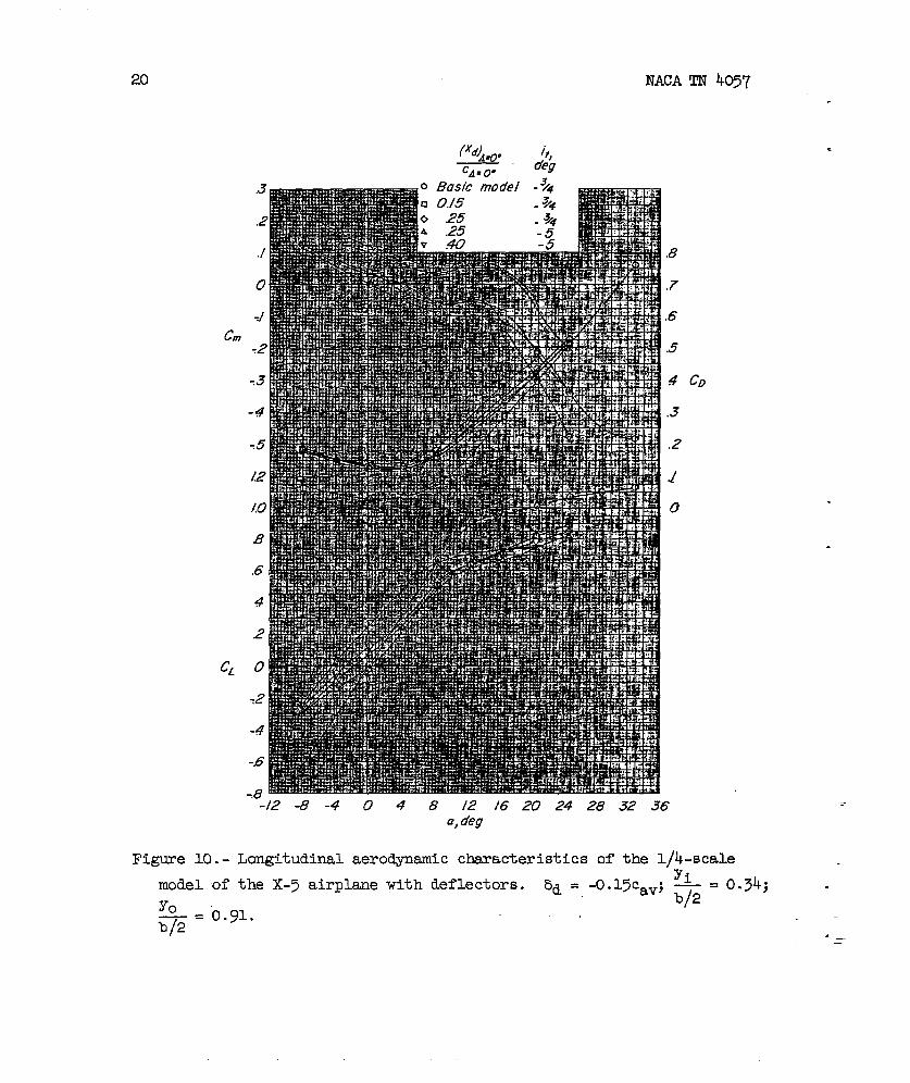
Figure 10.- Longitudinal aerodynamic characteristics of the l/4-scaleYi
model of the X-5 airplane with deflectors. bd = -o.15cav; —=o.3h; -
Yob/2
— = 0.91.b/2 ._—

NACATN 4057 21
cm
*A.
Basic model0.//4
.3
2
./
o
-tZ -8-404-8 E /6 20 24a, deg
Figure 11.- Longitudinal aerodynamic characteristics of the high-aspect-
ratio model with deflectors. Ed = -o.15c; ~ . 0.29; ~ . 0.96.b/2 b/2

22 NACA TN 4057
.
Center of slot,~ercenf ~Azo.
o Basic model
❑ 0./43
,5
4
3 CD
.2
./
o
.
.
.
“=/2 -8 -4 0 4 8 /2 /6 20 24~ a,deg
Figure 12.- Longitudinal aerodynamic characteristics of the high-aspect-ratiO model with spoiler-slot-deflector.”-bd = -0.075c; b~ = -0.075’c;
●
Yi 0.29; ~ s~=
0.49; slot width, 0.097cb/2 A=OO“
●

NACA TN 4057 23.
●
cm
&’,percent Cav
o Basic model❑ -7.5
6
.5
4
.3 CD
.2
./
o
a,deg
Figure 13. - Longitudinal aerodynamic characteristics of the l/&-seal.e
model
Yo—=b/2
of the x-5
0.84; it =
airplane
-5°.
with deflectors. c~)A=0°=03~,yi *34,. .—= . .cA~o b/2

24 NACA TN 4057
Figure lk.-mdel of
o
.3
,2
.2
-3
-4
.6
4
c’ .2
0
,2
-4
-,6
R
& ,percent co.
Basic model-5.0-i15
-/00
.6
.5
.4
,3
,2
./
o
.
.
.
“7/2 -8 -4 0 4 8/2/62024283? .a,~eg
Longitudinal aerodynamic characteristics of the l/h-scalethe X-5 airplane with a spoiler-slot-deflector. 5s = -0.025cav; .
Yi=0.35; — Yo=0.34; —= 0.84; it = -5°.
b/2 b/2 .,: . —

c.
NACA TN 4057
c.
c’
25
&,percent Cav
,6
.5
4
,3 CD
,2
./
o
.
.
a,deg
Figure 15.- Longitudinal aerodynamic characteristics of the l/4-scalemodel of the X-5 airplane with slant spoiler-slot-deflector.
8s = -o.025cav; h= o.~y; x . ..34; k. 0.84; it= -5°.b/2 b/2
CA====O

26 NACA TN 4057
Figure 1model
o
8d,percen f Cov
Bosic model
--/2 -8 -4 0 4 8 /2 ./6 20 24 28 32a, deg
CD
.6. - Longitudinal aerodynamic characteristics of theof the X-5 airplane with a butterfly-valve errangen
‘P%@ . o.~~; ~ = 0.34; * = o.~;-o. 025cav;Cfk==o
1/4-s=nt.
%=
tale
-5° ●
.
●
NACA TN 4057 27
.0
&,percent Cav
Basic model-50-Z5
-/0.0-/5D
4
.3 CD
.2
J
o
Q, O@
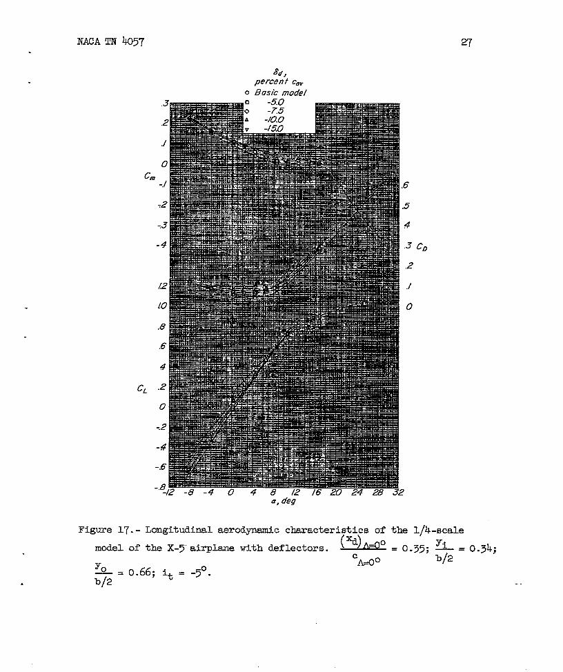
Figure 17. - Longitudinal aerodynamic characteristics of the l/k-scale
( )Mxd
model of the X-5”airplane with deflectors.o= 0.35;
Y~— = 0.34;
cA~o b/2Y.—= 0.66; it = -5°.b/2

28 NAC!ATN 4057
0
c.
CL
8~,percent CO,
Bosic model-5.0-Z5
-/00
Figure 18.-model of
()xd
A=OO
cA=OO
a,deg
Longitudinal aerodynamic characteristics of thethe X-5 airplane with a spoiler-slot-deflector.
Yi= 0.35; —= 0.34; L . 0.66; it = -5°.b/2 b/2
.
.
.
l/4-scale88 s -o.025cav;
.
.
.
.
NACA TN 4057
ad,percent Cov
29
.5
.4
,3 CD
.2
./
o
‘-/2 -8 -4 0 G 8 /2 /6 20 24 28 32a, deg
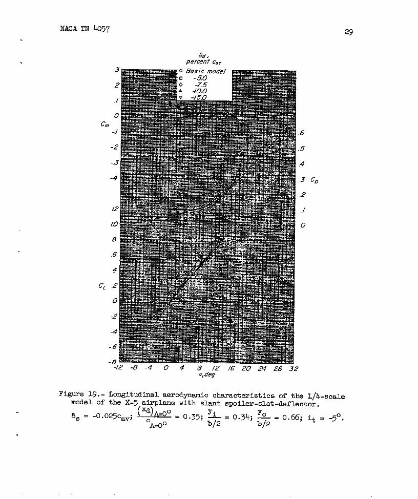
Figure 19. - Longitudinal aerodynamic characteristics of the I/k-scalemodel of the X-5 airplane with slant spoiler-slot-deflector.
(xd)A40=055, yi ~34,yo *= itas = ~.025cav; ~ .—= . . —= . -5°●
A~O “; =
b/2 b/2
30
0
NACATN @7
&,percent Cav
Basic model
.6
.5
#
.3
.2
./
o
72- -8 -4 0 4 8 /2 “/6 20 24 28 3;Q, deg
.
.
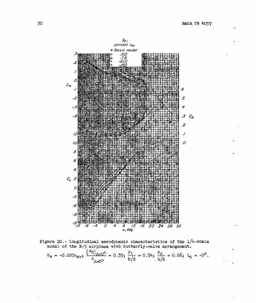
Figure 20. - Longitudinal aerodynamic cbaracteristics of the l/4-scalemodel of the X-5 air-planewith butterfly-valve arrsmgement.
8s =(%)~_O .035, y, Y~-o. 025caV; . “ —=-0.34; —= 0.66; it = -5°.
cA=Oob/2 kI/2
. .
#

NAC!ATN 405)7 31
Deflector spon
C*
.
.
6
,5
.4 co
.3
.2
./
o
‘W42 -8-4048 /2 /6 20 24 28 .32 36a, deg
Figure 21.- Longitudinal aerodynamic characteristics of the l/h-scalemodel of the X-5 airplane with deflectors. ad = -Q%av;’
()xd
A=O” =0.25; ~ = -3/4°.cA+”
32
c.
CL
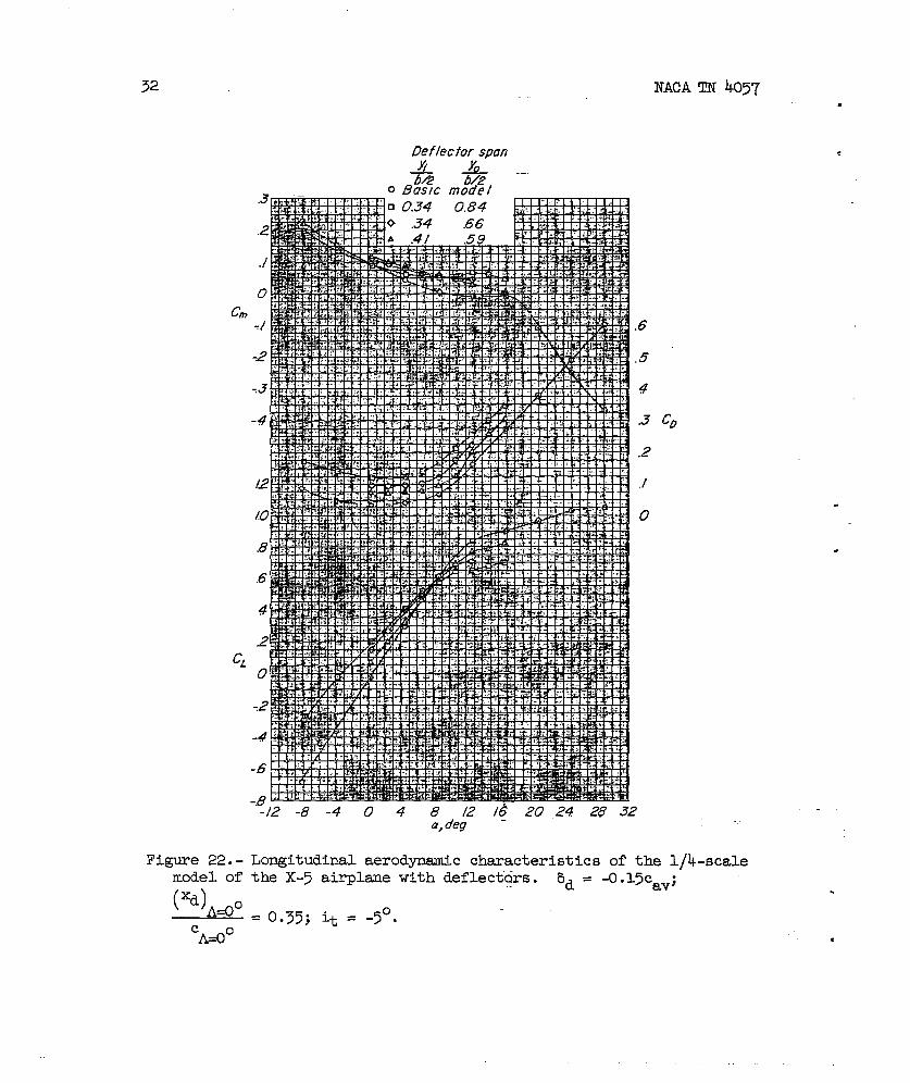
Figure 22. -
model of
(xd)Aao
cA=OO
NACATN 4057
..Deflector span
.6
.5
4
.3
.2
./
o
~/2-8-4048 /2 /6 20 24 28 32a, o’eg
Longitudinal aerodynamic characteristics of the l/4-scalethe X-5 airplaue with deflectkirs.
‘d = -o.15cav;.
= 0.35; it = -5°.●
.
,

-mw
.
NACA TN 4057
.
.
.
2
./
ocm
-J
-2
-.3
-4
A
(!0
.8
6
4
.2
+
76
.8 I
33
i7eflecfor span
-&A
.6
.5
4
3
2
./
o
J2 -8-4048 /2 /6 20 24 28 32a,deg
Figure 23. - Longitudinal aero@namic characteristics of the @-scalemodel of the X-s airplane with a butterfly-valve arrangement.
bd =(%) _@
-o.15cav; as s -o.025cavj A- = 0.35; it = -5°.cA~o

34
a,deg
o
❑
A’pefce;tcay
Basic mode/o
NACA TN 4057
.
.
Figure 24. - Longitudinal aerodynamic characteristics of the l/4-scalemodel of the X-7 airplane with spoiler-slot-deflector. ad’= -o.15cav;
(-JA~O ‘i =034, y0 08h %
c ‘0”35; ~ “ “~=”; = -5°.
A=OO
.
.

NACATN 4057.
‘0
cm
.
.
.
,
a, deg
35
&, Ho/e com’itbnpercent cav
o Basic model A// ho/es ssoledn -/0.0 A II holes sealed
.6
.5
4
.3 CD
.2
J
o
Figure 25. - Longitudinal aerod-ic characteristics of the l/~-scalemodel of the X-5(*)A4C) .035,P .“
-A#
airplane with various slot-cleflector sJws&ements.Yi Yo
= 0.34; — = 0.84; it = -5°.~ b/2

w
8d, 8s, ~ &o-l
percentcOv Percentcuv ZZ 772
—— -5: -:5
?
074 z
-5.0 -25 .34.66 Butterfly -vatve urranpmenf
—- —
-150 -25 .341
B4 spoiler-slot-deflector—-- —
—.-. — -/50 -2.5 .34 .66
Figure 26. - Effect Of spsm of the, spoiler-slut-defl.etia ml butterfly-valve arrangement on
t~ afiron effectiveness for ba = KIOO
(xd)A~o
on tlm l/4-scale model of the X-5 airp-.
= 0.35.CMO
a , , , ●

m.
.NACA TN 4057
I 6“ =-O.ECOV
d =C.vLeft wing
~::o:
--- .
Right wing
i
37
— 1 &=-0J5CCWdp
8!=-o.05c~~Left wing
— — G!34066—. — .34 .84
Q, deg
Figure 27. - Variation of rolling-moment coefficient with angle of attackfor a cod ination gust-alleviation sad lateral-control device on thel/4-scale model of the X-5 airplane.
NACA -Langley Field. V“.