technical memorjlndums —-m-mm+w n.a.c.a. technical. memorandum no. 904 the middle of the...
TRANSCRIPT

Wly... ..–=.... ...-=..- -
‘1!.-
3 1176013490488
S@-4pfj
TECHNICAL MEMORJLNDUMS w—-m-mm+.“”,,..,’,--—
NATIONAL ADVISORY COMMITTEE FOR AERONAUTICS.-.-.-=.=-
‘\
.—. -. .—
No. 90.4 ‘
STABILITY OF RECTANGULAR PLATXS WITH LONGITUDINAL OR “
TRANSVERSE STIFFENERS UNDER UNIFORM COMPRESSION
By R. Barbr6
,.,=...,. ..,, ,,. ... ,,, ,, . ,,
WashingtonAugust 1939
1
https://ntrs.nasa.gov/search.jsp?R=19930094512 2018-06-26T21:07:25+00:00Z

s,. --,. .
r
NATI.O~AL ADVISORY COMMITTEE FOR-AERONAUTICS
———
TECHNICAL ME!MOBANDUMNO. 904-—J,, ..–,, _... .._ ., .--y
STABILITY OF RECTANGUUR IPLA~ES WITH LONGITUDINAL OR”’”’
TRANSVERSE? STIFFENERS UNDER UNII?ORM .COMI?RESSION*
1. INTRODUCTION
The proper application of stiffeners, i.e., stiffen-ing ribs fixed to a plate, leads to an increase’ of the
Lg strength of rectangular plates. In’calculating.c?dplates, we have to distinguish’ %etween:
Plates with large spacing of the stiffeners inhe lending stiffnesses of the plate and ribs appearely in the calculation, and
Plates with small stiffener spacings for whichding stiffness of -elate and stiffeners in the direc-the stiffeners ca~ be combined to a new bendingSs, provided the stiffeners all have the’ same cross9 In general, we are allowed to treat such plates
as orthotropic plates.
The first investigation on the stability of plates,corresponding to 1) a%ove, was made by Timoshenko (refer-ence 2), who calculated the buckling stress of plates withone, to three longitudinal or transverse stiffeners withequa”l spac”ings. He conq$dered hinged plate edges and twoloadings, uniforti compression and pure shear. It is wellto note here that in the following discussion’ those stif-feners in the direction” of the normal loading are calledlongitudinal , and those perpendicular to the direction ofloadi’ng are called transverse.
Timoshenko uses the energy method for solution, amethod which was applied by Bryan (reference 3) in hisclassical work on the buckling of a rectangular plate, andwhich was later o“~ -’ taking into consideration the massforces -- exactly ‘proven by Reissner (reference 4). Recent-ly the stiffened plate with one longj.tudina,l stiffener in.—-———..— _______ ______ ____
*ilStabilit&t .gleichm&ssig gedr~ckter Rechteckplatten mitL&ngs- oder Quersteifen.lt Ingenieur-Arclliv, vol. 8,no- 2, 1937, pp. 117-1500
I

2 N.A. C.A. Technical. Memorandum No. 904
the middle of the compression field, i.e. , the middle ofthe plate, stressed by pure bending, compression, or shear,was considered hy Chwalla (references 5 and 6), and theproblem was”&olved a“lio with the aid of the energy method.
In the application of the energy method, the ~~ave formis assumed to he represented by a series which satisfiesthe boundary conditions, ,and the coefficients of which aredetermined by minimum energy considerations. : The more ex-actly the assumed shape of the wave pattern agrees withthe actual pattern, the less terms in the summation arenecessary for a sufficiently accurate calculation of the%uckling stresses. Exact buckling conditions in a finishedform cannot %e developed with this method. However, forsome cases, concerning the loading and the reactions of theplate, we have complete solutions of the differential equa-tion and in these cases the “Duckling conditions can be rep-resented exactly. As the stiffened plate consists of a num-ber of nonstiffened. ~rips which are connected with eachother along the stiffeners, the solutions of the differen-tial equation for the nonstiffened plate can %e accordinglyapplied to the stiffened plate.
??or the unstiffened plate Timoshenko (reference 7),Reissner (reference 8), and in a more complete manner,Ch?valla (reference 9) have set up the %uckling conditionsfor uniform compression in one direction, the loaded edgesbeinq hinged with optional support of the longitudinaledges; with the aid of the complete solution’of the differ-”ential equation. The solutions for supported transverseedges and hinged longitudinal edges originate from .Schleicher (’reference 10).
With shear stresses, complete solutions are known onlyfor the infinitely long strip. The fundamental investiga-tion for this is the work of Southw%ll and Skan (reference11), in which ‘pure shear stress with hinged and fixed lon-gitudinal edges is investigated. Schmieden (reference 12)develops solutions for combined shear and compression ofthe infinitely long strip.
,In the present paper, the complete buckling conditionsof stiffened plates” are being developed for uniform compres-sion. We shall treat plates with one or two longitudinal
,, or transverse stiffeners at any point, discuss the lmckliwconditions, and eval’uate them for different cases.
—
N.A. O.A. Technical Memorandum No. 904 3
For the special case with any number of longitudinal..-, sti.ffqners with equal dimensions and witk equal spacings,
Lokshin (reference 13’) h-ascalculated -the buckli.n.g,..cqniii=tio’ns. However, as we shall prove in the following”, thesebuckling conditions are not complete.
II. PLATI!!WITH LONGITUDINAL STIFFENERS
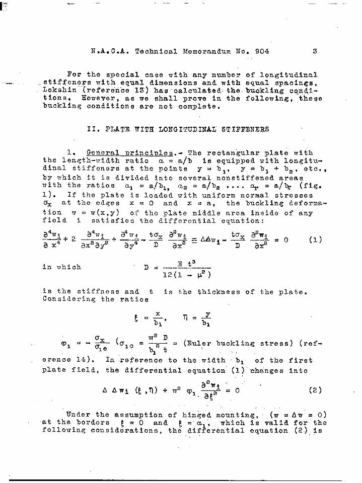
1. General Erincimles.-..——. The rectan@ar plate withthe lenqth-width ratio a = a/3 is equipped with longitu-dinal stiffeners at the points y = bl, y = 1)1 + %J2, etc.,
by which it is dibided into several nonstiffened areaswith the ratios al = a/bl, CL2 = a/b2 ....~= a/~ (fig.1). If the plate is loaded with uniform normal stressesox at the edges x = O and x = a, the buckling deforma-tion m = ‘w(x,y) of the plate middle area inside of anyfield i satisfies the differential equation:
in which ‘D= E t=————- ——---12(1 -Vz)
is the stiffness and t is the thickness of the plate.Considering the ratios
In .Teference to the width bl of the firsterence 14).
plate field, the differential equation’ (“1)’’cha’ngesinto,
(2)
,,
Under the assumption of hinged mounting, (w = Aw = O)at the borders E = O and e“=’al, which is valid for thefollowing consideratioils, the differential equation (2),$s
,. “
4 N.A.C.A. Technical Memorandum No. 904
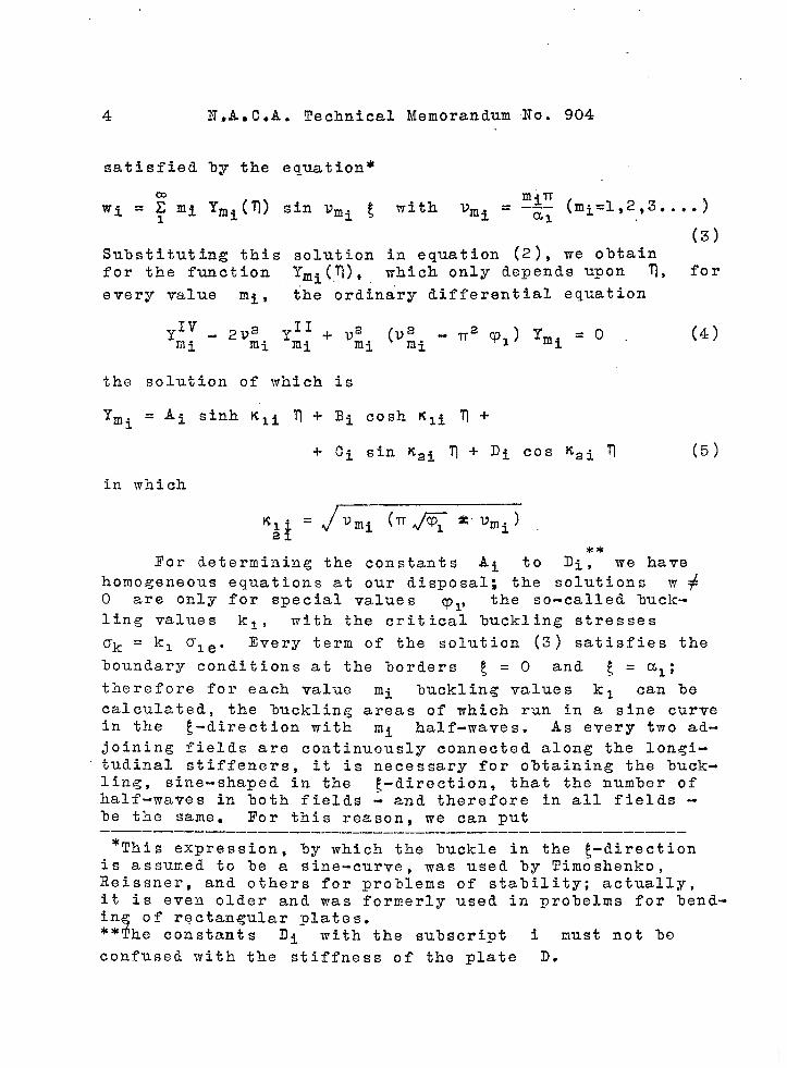
satisfied by the equation*
(3)Substituting this solution in equation (2), we obtainfor the function ymi(’0). which only depends upon n, for
every value mi , {he ordinary differential equation
the solution of which is
‘Ymi = Ai sinh Kli ‘1’l+ Bi cosh Kli ~ +
+ Ci sin Kai ?l+ Di COS ~2i q
(4)
(5)
in which
**For determining the constants Ai to Di , we have
homogeneous equations at our disposal; the solutions ~+O are only for special values Cp~$ the so-called 3uck-ling values kl, with the critical lmckling stresses
ok = kl ale. Xvery term of the solution (3) satisfies the
boundary conditions at the borders t = O and [ = ~1:therefore for each value mi ‘ouckling values kl can becalculated, the buckling areas of which run in a sine curvein the ~-direction with mi half-waves. As every two ad-
joining fields are continuously connected along the longi-tudinal stiffeners, it is necessary for obtaining the buck-ling, sine-shaped in the {-direction, that the number ofhalf-waves in %oth fields - and therefore in all fields -be the same. For this reason, we can put————__— ________ ________________.________—_—
*This expression, by which the buckle in the ~-directionis assumed to be a sine-curve, was used by Timoshenko,Reissner, and others for problems of stability; actually,it is even older and was formerly used in pro%elms for bend-in.
$of rectangular plates.
** he constants Di with the subscript i must not he
confuse”d tvith the stiffness of the plate D.

I?.A. C.A. Technics.l Memorandum.No.,904 5
mi I=m, %li = Vmt K:~ ‘“K~
The values KI “ “ K2and “a’re“re’aif“or the “actuallyoccurring cases, since the buckling stresses of the stiff-ened plate, whose borders ? =Oand Tl= 1/%1 = B are
generally strengthened by some form of support, are greaterthan the minimum values of the real solutions (n#/z; = Vm)
which give the Euler critical stress
ma IT2 D~k = ———.—.a= t
of the strip with the length “a, whose longitudinal edgesare under uniform compression
As will be shown in the next section, we have, fordetermining the 4r constants Ai, Bi, Ci, Di (i = 1, ~,
● *9 r) four boundary conditions at the horders o = O and
and ‘0= b/bl = ~ and, furthermore, 4(r - 1) transition-al conditions at the stiffeners which form a system of 4rhomogeneous equations. We Obtai.il the buckling conditionwith the aid of these equations by putting the determinantof the denominator equal to zero. Cnly the minimum valuesof the roots of the buckling equations are of interest, theother roots representing higher lmckling values,
The buckling values “k” with respect to the totalwidth b of the plate, i.e., (reference 14) k = Ox/Oe ,are calculated from kl :
2. Boundar~and transitional conditions.- At the———. —borders ~
—-—_________ ____ ____= O and n=$, the plate is generally con.
netted to edge supports. In many cases these supportshave relatively large and compact cross sections, so thata certain elastic mounting of the plate with them is given.This mounting should be taken into account in the general%oundary conditions. (See reference 9. )
For the stiffeners and supports O to r, respec-tively, we introduce the following notations:
6 “N.A. C.A. Technical Memorandum No. 904
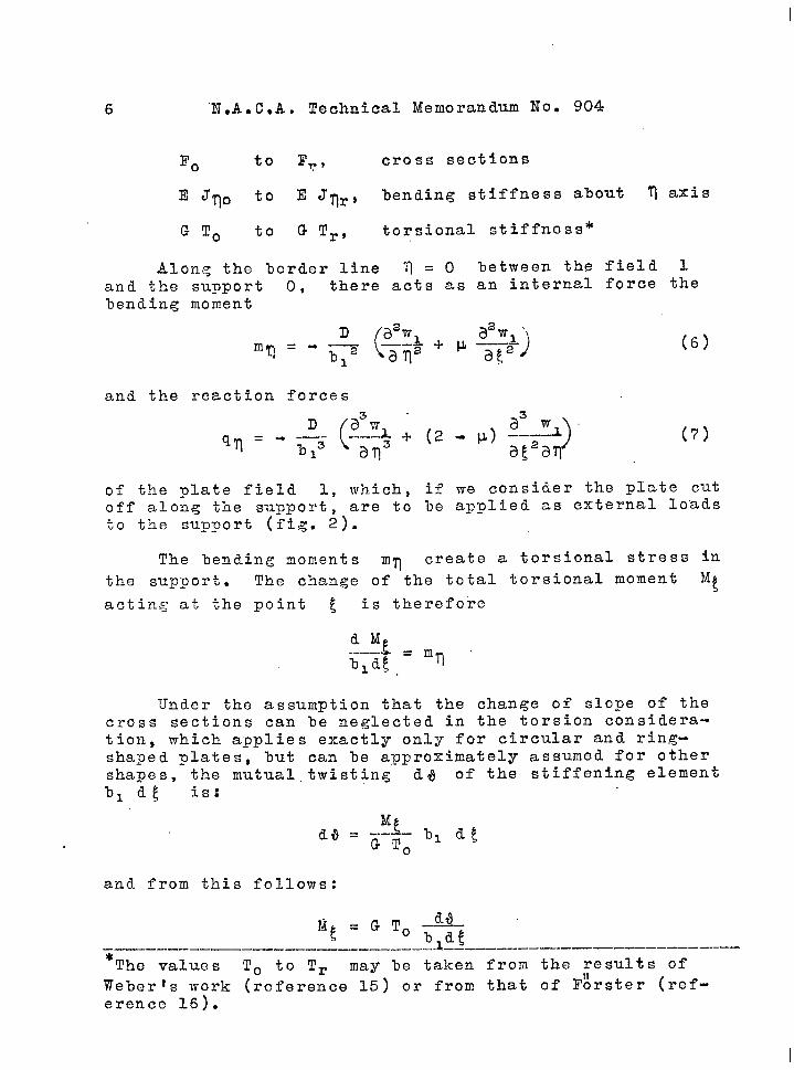
F. to Fv, cross sections
~ JTO tO E J~r> bending stiffness about t axis
G To to G Tr, torsional stiffness*
Alonq the border line ‘il= O between the field 1and the support O, there acts as an internal force thel)ending moment
(
2 a2~ ‘1a ‘1 * ~ ___A
“T=”+xi=(6)
3~2~
and the reaction forces
D
(
3 3
qm = “ ;2-)’
s+ + (.2 . ~) ~–fl~
aq af2aq(7)
of the plate field 1, which, if we consider the p~ate cutoff along the support, are to be applied as external loadsto the support (fig. 2).
The bending moments mq create a torsional stress in
the support. The change of the total torsional moment ‘tacting at the point ~ is therefore
Under the assumption that the change of slope of thecross sections can be neglected in the torsion considera-tion, which applies exactly only for circular and ring-shaped plates, but can le approximately assumed for othershapes, the mutual. twisting d~ of the stiffening element1)1 d~ is:
and from this follows:
~.--.-.----------____-__-.-A-=-----------------------
The values To to Tr may be taken from the results ofWeber:s work (reference 15) or from that of l?~rster (ref-erence 16).

N.A. C.A. Technical Memorandum .No.. 904 7
On account of the contj,n~ous connec’ti.on of stiffener,.. and-plate, the twisting of the stiffener $s equal
slope of the plate, i.e.-~ ,...,,
, ..
a~W~
*tan4=—-bl am
therefore
=G!CO d23 a3w1.mn
.-— —- =GTO -——-.l)le d~z b13 a g,2am
so that the first boundary condition at the ‘pointis
D(
3?fv?l * ~ a2w1
~zr. —-
~~ )———3[2 = G To —-~fl~5--
1 b13~~t171
to the
,’
V=o
(8)
The reactions qq of the plate field 1 create in thesupport a bending moment Mv about the q-axis, assumingthe border of the plate to be at the shear center of thesupport. If, at the same time, the support is acted on lythe compression stresses Oxk , then, at its ends, we havethe compression forces
P. = axk To = kl ale F.
which at the point ~ induce the bending moment, P. WI .For the bending of the stiffener which, on account of thecontinuous connection between it and the sheet, agreeswit’h the deflections WI for 9=0, we have thereforethe differential equation
From this, by differentiating twice with respect to g asecond boundary condition for ?l= O is obtained:.“
(9)
For the support r, i.e., for ~ = P, the corresponding
I 111111111111111 ,- --,,----

8 N.A.C.A. Technical Memorandum No. 904
%oundary conditions are
(lo)
and
Between the adjoining fields i and i+l, thereis the stiffener i’ with the cross section l?i and the
moment of inertia Jvi about the ‘n-axis. At the’ stiff-
ener, the conditions of continuous connection to the sheethave to be first satisfied. Therefore, for
we obtain
and
(13)
Since the cross sections of the stiffeners generallyhave I, L, or Z forms, indicating no great torsionalstiffness, we may neglect the torsional stress which oc-curs in the stiffeners due to the bending of the plate.The experiments of Erlemann (reference 17) justify thisassumption. The moments m~ of the fields i and i+l
at the stiffener are therefore equal, i.e. ,
Along the stiffener, we have, as a further condition ofthe continuity
(14%)
so that the transitional condition” f14a) becomes

,p- -. ——
N.A.C.A. Technical Memorandum No. 904 9
Considering the fields i andstiffener, a transitional condition
(14.)
i+’1 as cut off at thecorresponding to bound-
ary condition (9) applies, but instead of the’ reaction forceof the border field, the difference between the reactionsof the fields i and i-l-l, adjoining at the stiffener,have to he introduced. Therefore,
(Z5a)
Considering equations (13? and (14b), we have at the stiff-ener,
(15b)
so that the transitional condition (15a) is simplified to
(15)In the term on the left side and the last term
of the right side, the index i of w may be replaced%y i+l, as it makes no difference to which of the ad-joining fields the deflections of the stiffener are refer-enced. Equation (15) applies exactly only to the symmet-rically connected stiffener, the neutral axis of which co-incides with that of the plate. In many cases, the stiff-ener will %e fastened only on one side of the plate, Inthis case, according to the proposition of Timoshenko (ref-erence 2), the moment of inertia J?ti must be referred to
the axis which lies in the connecting surface between thestiffener and plate. The additional stresses in the platewhich arise from this condition are not taken into consid-eration. They fade very fast along the effective width inthe ~-direction, according to statements hy Chwalla (refer-ence 18).

—Table 1
—
I
~
.i
4
5
6
7
s
a i~lcl~l e
(;1.
(s’) -- v,%, \ + el I - Y.%* I —e, I
.——
..—.
.——.. .. . . .
(1
—-___–,_.__. ------- ._, —-. .—.——00 I + X*c% — q
I
’03=8iBh@ =CO*
f
B,
g ‘1 hc% D,
I
——
— sinXz — Cosx,
—%, Cos%, \ +x,sinx,
— e,sin/1x, —e*cosf!lx,+Y2x*cos /?%* — Y,X2sin~X8
—%, c,Cos/l%,I
x,Casin/?x,— @*sin@X2 — @*Cos$X*

N.A. C.A. Technical Memorandum Ho. 904 11
,.
In the following, we take the ratios” b“etheen bending,.stiffnesses, dbpendent..upon the cross sections of the, stiff-eners, and those of the plate from Tirnoshtinko (“reference--2):
and, to abbreviate, we place
and
After introducing the solution (3) in the boundaryand transitional conditions (8) to (15), the followingequations, independent of ~ are obtained, which servedetermine the constants A to D in the fuilctions Y. Inthese equations the index m (m = num%er of half-waves
to
inthe ~-direction) is omitted for reasons of simplification.
Yr’’+llfr Yrh+.Lv2Yr =0
}
(lo’)for 7=$
+ Y;*U (11 ‘)v= (2-p) Yrt - or Yr = o
1Yi -Yi+l =o (121)
Y{.-.y;+l = obl+ba+ ... +bi (13~)
for =T .———-~Y;’ - Y:+x =0 bl–--––-
(14’)1!f
‘Yi + Y~~l+@iyi= O (15’)

12 N.A..C.A. Technical Memorandum No. 904
3. Plate” with one longitudinal stiff ener. -= In the——.——.——. ——————= —————-——.—.———-————.,.case of one longitudinal stiffener,. r = 2. With the so-lutions,
WI = Y1 sinv ~, Y1 =Al sinh Kl?l+ B1 cosh K1 ~ +
+ c1 sin K2 ?l+ DI cos K= Tl,
-1- C2 sin K2 q + D2 cos K2 q
we o-otain from (8 !) to (15 ~) a system of homogeneous equa-tions, the coefficients of which, with the abbreviations
2el = K1 - I.@, e2 = K22 + v V2
Cl = K12 - V2(2 - p), ‘2 = K2a + V2(2 - V)
(el + ea = c1 + C2 = K12 + K22)
are shown in table 1. This table is, at the same time,the denominator determinant to %e solved, the lines ofwhich are denoted by- the numbers 1 to 8, and the columnsby the letters a to h.
a) Solution of the determinant and the general buck-———————._———.—___————____——__———— _————_————lin~ conditions.- Solving this determinant, we denote thesuldeterminants as follows:
I1,2a -b9
is the su%determinant which is o%tained from the completedeterminant %y canceling the lines 1 and 2 and the col-umns a and b. The determinants marked .with overliningare to be forined from the su%detcrrninants on the left sideof the equation.
After eliminating the lines 1 and 2, the determi-nant becomes: *

N.A.C.A. Technical Memorandum No. 904
)Id
1,2+ K2 (Wo@o+c2e Z C,
..,.
13
(16)
The lines 1 and 2 contain oni.y the unknowns Al to Dl, the
lines ‘7and 8, only the unknowns Aa to D2. According to
this, the lines 1 and 2 are independent of the lines 7 and8, so that in the following elimination of the lines 7 and 8,the subdeterminants
II1, 2 1, 2
Ia, II ‘ ● “” c, d
with p = a, b, c, and q = b, c, d (p + q) occurringin (16), may he generally deiloted by
+@2(Kla+K22) sinh ~ KI sin ~ Ka +—.——
II7, 8+ Ya K1 K2 (K12+K22) cosh ~ K1 cos s Ka] ~, ~

(17)
The solution of the remaining subdeterminants withfour columns gives the following values:
I,z,7, 8 0,a, b, e, f =1>Z, 7, 8 . — @l X2 (x; + x;) CofxlcosX2,a, b, e, gI,2,7, 8
= — CDlX2 (z; + 2$) Cof2t1sinX2,a, b, e, h1>Z>7, 8 _— — 01X2 (z! + xi) SinxlcosZ2,a,b, j,gI>~,7, s _— — 01X2(z:+ z:)Sinzlsinz2,a,b, j, II

N.A.C.A. Technical Memorandum No..9@l 15
1,2,7/8~=+z1z2(x; +z;)2,a,b, g, h]
, ,...,. I,2,7, 81,= + @l.%2.(x~,+z:).6Di%lcos?2, ,, .,,.., _ ., ., -,,,a, c, e, fI,2,7,8’ = o,a, c, e, g
I,Z> 7, 8\_ — q %2(%; + z:) &D~2x~,a, c, e, h.i—
I, 2,7, 8 = + 01 ~ (x; + w;) CCE2X2,a, c, f, gI,2,7, 8a,c,f, h = (z;+@[–z1x2(z;+X1)401 (zlsinz2cosX2– X2GinxlQtof@],
I,2,7,8= + q xl(x;+ x;)Eoj% CosX2,
a,c,g, h
I,2,7, 8= + @l X2 (x; + x;) &ofXlsinx2,a,d, e, f
I, 2,7, 8= + CDl%2(X; + @ (Sof2x~,
a, d, e, g
I, 2,7, 8 =0,a, d, e, h
I,2,7, 8 = (xl+ ~g) [+ X1ti2 (z; + @ + COl(xl sinX2cos%2+ % Gin % ~oi%)],a, d, ~, g
I,2,7, 8= +01 zl (z? + x;) sin2%2,
a,d, /,h
I,2,7, 8= + ~lz (% +%) W%sin~2,
a, d, g, h
I,2,7, 8b, c, e, f
= +017t2 (x; + x:) Gin 7C1cos7t2,
I,2>7, 8 .b, c, e, g — q xl (z: + x;) COS2%2,
:’::’: = (xl+@ [+ X1X2 (x;+@ – @l (Xlsinx,cos X2 + ~2~i~ % 64 %)],>>>
I,2F7, 8b, C,f, g = o,
I,2,7, 8b, o, f, h = — $+ X2 (zf + @ 6iv2xl,
I,2,7, 8b, C,g,h
= +01 Xl(x;+ x:)Gin~ cos2t2,
I,2,7, 8b, d, e, f = -1-01X2(x:+ xi)Ginxlsin2t2,
127,8;;eg = (x?+@ [– x,X2(%+x:)+ @l (– Xlsin%,COSX,+ X,Gin % SOfXJ],,,>I,2,7,8 =
— @l ~ (x;+ x;)sin2z2,.b, d, e, hI,z,7, 8b, d, f,g
= + @lxi (x! + it?)Gina~,
1,2,7, 8b, d, j, h ‘o’I, 2,7, 8b, d, g, h = + @%(%+%) Gin% Sinxz,
I,2,7, 8c, d, e, f =“+ XiXg(z:+X8)*,

16 U.A.C.A. Technical Memorandum Xo. 904
I,2,7, 8 = — q%l (Z! + x;) 60[%1 Cos2$4,c, d, e, g
I,2,7, 8 — @lxl (x; + @ &ofxlsinx2,c,d, e,’h =
I,2,7, 8 = o.c, d, g, h
Substituting thes. values inte the sabdeterminants(17) and these again In (16), we obtain, by putting thisexpressicm equal zero and by arranging the members, thegeneral buckling condition:
(%:+ %:)[Z. + (Q + fq 2, + p. + ~2) 4 + (@oyo + @2~2) G +
+@o@2z4+ (@oY2+@2wo)z6+~o~2’%++(CDo@2!P0+@o@2Y2) z7+(@oyow*+ @2yoy2)z8+@0 ‘2YOY2Z9+ (1/3)+CD1(zlo+CDoz~~ +Qzlz+wozls.+ y2z14+@o~oz5 +@2y2&+
+@o@2z,7+ ooY2z18+@2yoz19 +yo~2Go+@o@2~oz21++ootD2Y2z22+f30Yow2zw+ @2~oy2z2,+@o@2~o~2z25)l ‘o. I
In %hzs equation$
(+z2c2e1 —xlGin$xlsin ‘Bj:)“+x2cos@c2Ginx1Gin(~-I)xl)],(p–%;)~,cos

l?.A.C.A. Technical Memorandum No. 904 17
.,
From this general buokling condition there can bederived a number of spee$al cases aonaerning the bound-ary conditions which., however? can only be solved witha great amount of calculation. In the following we ehalldiscuss and evaluate numerically two simple limitingcases, namely, hingedand fixed longitudinal borders, re-spectively. .
b) ~in~eil lon~itud nal borderq.- Eor hinged, butrigid mountirig (w = Awi= O) of the longitudinal bordersTI=O andll=b/bl =@, we have To= Ta=Oand Jqo= JTa=a, so that

N.A. C.A. Technical .Memorandum No. 904
After dividing equation (18) by the factors @o and
Q2 the buckling condition becomes:
(Kla -1-KS2) [z~ + 4?1 21,] = o
or
- 1$~1$~(K12+ K22) sinh PK1 sin (3K2
1
~ @l [- K1 sinh p KI sin K2 sin (~-1) K2 ~ (19)
-1-K2 sin P K2 sinh KI sinh (P-1) Klj = O
in which the factor (K12 -1-K22) has %een left out, as
it cannot %ecome zero according to hypothesis.
For the limitation, that the ratio of the fieldwidths hl/1)2 is a real fraction, a further splitting of
the buckling condition (19) is possible. This limitationis given l)y
%1 = r~, %2 = SC
in which r, s and r+s =U are positive whole numbers.With
.!s1 . t !!~=Kfr K1 ‘ r 2
the buckling condition (19) becomes
-K1K2(K12~K22) sinh u Kll sin u K21
+Q1(- K1 sinh u Klf sin r K21 sin s K2 1
1
+ 1$2 sin u ~2 sinh rKl! sinh s K1l)
or, since the left side contains the mutualsinh Klt and sir. K2 *
r
[
sinb u K1’sinh Klt sin K2t -KlK2(K12+ K22) — ——.——.—
sinh K1’
J=0
factors
sin u K21—————.sin K21
(sinh u Klt sin r K21
~ Q1 - KIsin s K2t––––..–––r-. ———..———.————.-—.—. +
sinh K1 sin K21
sin u K2f sinh r K1l sinh S*K1 1+ K2
)]——.-————— -—————__—————..—— = osin Kat sinh K1l 1
(20)
(21)
—._._
N.A. C,A. Technical Memorandum No,. 904 19
in.which the quotients in the large brackets are related. . terms .- .-,.: .........—...,. .,.,....... ..... .,. .-
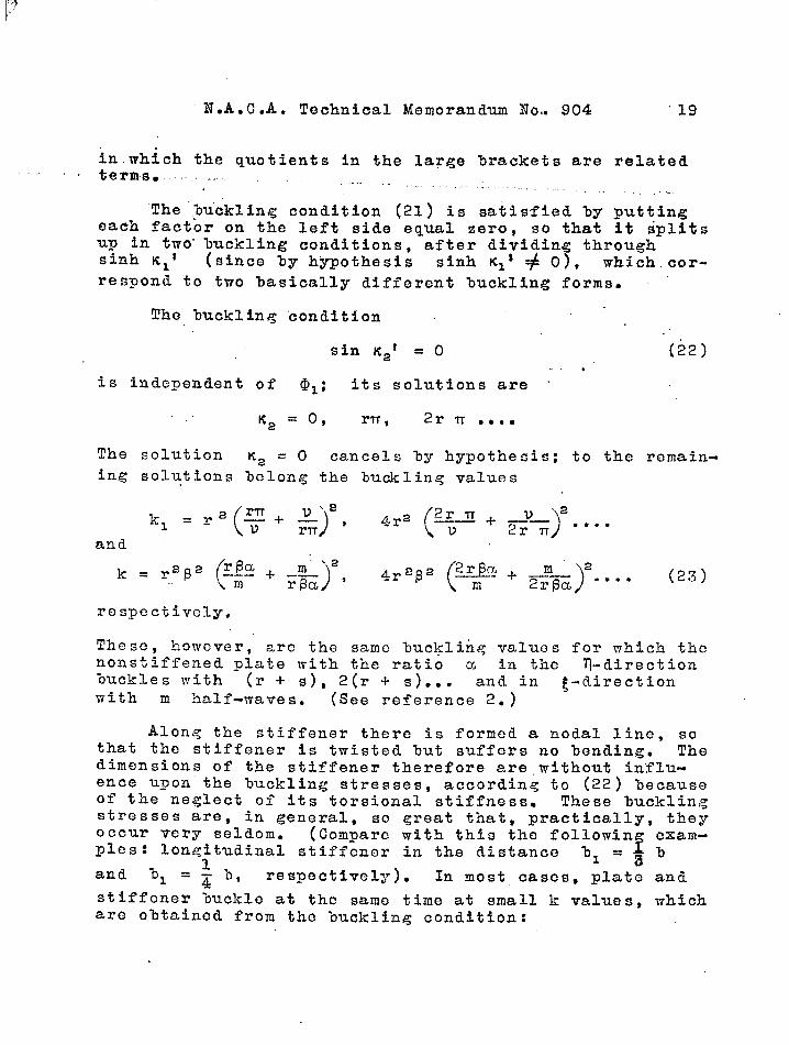
“The ’chuckling condition (21) is satisfied by puttingeach factor on the left side equal zero, so that it dplitsup in two” tiuckling conditions, after dividing throughsinh Kll (since by hypothesis sinh Klt # O), which cor-
respond to two basically different buckling forms.
The buckling condition ~
sin K2t = O “(22).,..
is independent of o~ : its solutions are ‘
Ka = o, rn, 2rn .,.=
The solution ‘2 = O cancels %y hypothesis; to the remain-ing solutions belong the buckling values
respectively.
These, however, are the same %uckling values for which thenonstiffened plate with the ratio a in the n-directionbuckles with (r + s), 2(r A s)... and in ~-directionwith m half-waves. (See reference 2.)
Along the stiffener there is formed a nodal line, sothat the stiffener is twisted but suffers no hendin.g. Thedimensions of the stiffener therefore are,without in”f3u-ence upon the buckling stresses, according to (22) becauseof the neglect of its torsional stiffness~ These bucklingstresses are, in generals so great that, practically, theyoccur very seldom. (Compare with this the followin exam-
fpies : longitudinal stiffener in the distance ‘bI = ~ b
and hi = ~ b, respectively). In most cases, plate and
stiffener buckle at the same time at small k values, whichare obtained from the buckling condition:

20 N.A* C.A. Technical Memorandum No- 904
formed by putting the last factor in equation (21) equalto zero.
Not considering the higher buckling stresses, the%uckling values grow according to (24) as the stiffnessVL = ‘Y increases (see following examples) and reach at
Y = m: i.e., for a knife-edge mounting cf the plate alongthe stiffener, their maximum values. Since at Y = m
@l =m, the buckling condition for knife-edge mounting
along the stiffener is o%taincd from (24) ‘byplacing thefactor of @l equal to zero; the lmckling condition istherefore :
sin r 1$~‘ sin s K21 sinh r K1* Sinh s K1l+——————-.——————-_—_..— —-——— ..———————————— — =0 (25)
K2 sin u K21 K1 sinh u Kll
c) Examples:
1. Longitudinal stiffener spaced at bl =~hand——-- ———-.-...———-..——————— ..——— .. .111 = * b, respectively.- Having one longitudinal stiff-
ener at bl = ~ (r = 1, s = 2), the ?mckling stresses
are, using (22) and (23), respectively,
In this$ the first terq (luckling ~orm: 3 half-waves in ‘k
direckion (see fi~. 3,1) contains the minimum values k =
9x4 = 36 with ~m- = ‘1; i.e., for the ratios a, = 1/3 at
m= l,ct= 2/3”at rn=2... For a longitudinal stiff-ener at a distance 31 = 3/4, the corresponding bucklingvalues are
The buckling stresses according to (24) and (25) (bucklingforms, sce fig. 3,11), are calculated for the same valuesof Y an d 8 and plotted against a in figure 4. The Se

..—
N.A ..C.A. Technical Memorandum .N.o.,9.04 21
buckling stresses are, even fbr., Y = m, essentially smallyer, than the ones from (23) with..the minimum values k =36,and 64, “-”respecti”vely~ so-ilia.tthe bu’cklin”g’-”condi-tidn(22) has no practical signi$ieance. .. . ‘ .
The buckling-stress Cur-ves’f,rom (2?5)3 i.e., for Y =e ‘ifigs, 4 and “5) ha~e no points of inflection, similarto the” axes for Y = 6 = O ,’(nonstiffened plate), hut each
(has on’1.ya minim”um k = 10.’6~ l--
for =% i’
k = 8.55 for
I)l 1--1) )‘z’
so tha:t the plate’ ‘buckles in ~-direction in the
sequence 1,2,3 ,*** half-=wav,es for increasing values of a.Eowever, for finite values of Y some of the curves havepoints of inflection; for, Y = 10, in the examples, thecurve even has a’ maximum and consequently, two minima.From this fact f’ollows that the plate in the. examp”le%1/% = 1/3 ‘and Y = 10 buckles for increasing values of
the ratio a, i.n the following sequence of the longi.tu~. ~in’al waves m:
—._— . . . . . . __________ ———————————.———-——-‘8 = ‘o ‘6 = 0.1—-————__________ _______
o
[
—7——-—..——--—-—.————.—.—.—— ———..—-
<a < 0.95 n = 1 0
I
<a < 1.00 m = 10095 c&<l.49 m=2 1.00 <a<l.26m= 21.49 <&c2.31 m=l 1.26 <a<2.64 m=l2.31 <~<3.02 .m=4
etc.
Gorr,ospondin,g relations are Shomn in the example bl/b =
1/4 (fig. 5). For large values of a the curves intheir range of validity approach gradually the value ofthe minimum with the smaller ordinate.
In table 2 the smallest %uckling values k are givenfor the ratios a = 0.6, 1.0, 1.4, 1.8. For the accuratecalculation o“f the numerical values the tables of circularand hyperbolic functions ~y Hayashi (Berlin, 1926) withseven’ and more figures were used.
,..

“N.A. C.A. Technical Memorandum No. 90422
I@———_
1/3
.—-.
1/4
.——
Y
-—_.
5
.——.
10
—.
5
-—.
I 10
-— —-.
6
00.s0.2.—— .00.10.2.————-00.10.2-————.00.s0.2
TABLE 2.—— ——— —_____ -— —__-.-- —-————-— -----
.—-— —-
0.6
9.8499.’?969.735.-——— —..0.215.0.201.0.186-————8.0628.032”‘7;999--————-8.3628.3178.308
.—.
m.—.1“11-—111—-111.—-1,11
1.0-———— —-8~9598.4137.861.—— ——
10.69710.65210;323.—= ——.—7.0156.8086.539-—-=——--8.2668.i287.979
m
11
1-—-
211“-—--111-——-111
,.,—--— —194.—. ——-
7:8527.0096.293.————- —
1002449.5498.742
.————— —.6 ;6436.1816.751.————— A-8,0967.7867.368
T_——-
m 1.8.— ——————1 797561 6.8081 ‘6.045.— ——————2, 9.754
1
1 8.6581 7.747—————.‘1 6.9971 6k4411 5;909.— ——-———2 8~1821 7.6591 7.104
-—-
m
1+1.—-111-—-111
211
2. Longitudinal stiffener in the middle of the_p&j~~-If the sti.~fener lies in the middle of the plate (Ill =
$’r=s= 1), the plate lnzckles according to equations
(22) and. (23) With one nodal line in the middle at the val-ues
( )
2’k =4 Z2+ m ● .* (26)
m 2;
the minimum values of which are k = 16 at the pointsa= + (m=” l), a=l (m =2), etc. .
The corresponding buckling forms are antisymmetricalto the center line ~ = 1 (fig. 6,1). The luckling con-dition (24) changes into*-------------------------------------------------------- .-————*The buckling condition (27) is also present in the gener-al solutions %y Lokshin (reference 13), in which, for thespecial case of an arbitrary number of equal stiffenersequally spaced, only the” symmetrical Wckling forms areconsidered. While in our case - same as in certain casesfor plates with an odd numler of longitudinal or transver-sal stiffeners - the antisymmetrical buckling cases can bederived without difficulties from the symmetrical bucklingcases with respect to half the plate width or length, thiscannot be done at an even numler of stiffeners. But theantisymmetrical buckling cases give in certain regions thesmallest buckling values, as will be shown later at exam-ples of a plate with tvo longitudinal or transversal stiff-eners.
.——-— .- ... ,, -,,..., ., ,,

lIg-.,,J
N.A. C.A. Technical Memorandum ~O. .9O4 23
,,in the Iirnitinqcase$, Y = ~, iti”become~ ““
,,,’
,.
,.tanh K1’ tan Ka o ..-——— - ——— =
RI K2. (2,8)
,. Equation (28) agree s”with the buckling cmdition of a platewith .the width %/2, one longitudinal b?rder of which ishinged and the other fixed (reference 8), so that the cor-responding buckling form is symmetrical to the center linen=l (fig. 6,11 b).
Tim6shenko (reference 2) calculated th@ smallest %uck*ling stresses for the plate with longitudinal stiffener inthe middle by means of the energy method.
Contrary to the example with one longitudinal stiff-ener at a distance %1 = %/3 or bl = 3/4, in our case,
bl = ?)/2, the buckling fdrm with tho ’nodal line at the
stiffener is of importance. With increasing Y, at first(2’7) gives the smallest buckling stresses., until at a Cf3r-tain value of Y, which may be denoted as minimum stiff-ness (ininy)~ the same -buc,kling values as with (26) are
obtiained. An increase of Y does not lead to a furtherincrease of the buckling ,~tresses, as the smallest Mck-ling stresses are then obtained from the buckling condi-tion (22), and (26), respectively, which is independent ofY, and for which the plate buckles with one nodal line atthe stiffener. Hence the value ~inY is at least required
to get the maximum value of a plate with longitudinal stiff-ener in the middle. The minimum stiffnesses have %een cal-culated numerically by the author in a special paper (ref-erence :19).
3. Dependence of the buckling_stresses on the posi--——..——— .—_..- —————. ——...—————- ——--—tion of t~~ longitudinal stif~enor.- The dependence of the-—--- —--——.— --.——.———- ———-buckling stresses k on the ratio lJJb , is s~own in -fig-
ur,e 7 for the square plate; for different values of V (at“8 = 0], accordin,q to (19). Tor reasons of symmetry, ‘thecurves run symmetrical to the center line %1 = 0’;5. In the
case of the stiffener lying at the bord’er ~ = O (bl/b = O),
the buckling values for.every value Y, with any ,but fi-nite maqnitude, are equal to those of the plat,e”hinge& at
IL.
24 N.A. C.A. Technical Memorandum No”. 9’04
the four sides; thus, k = 4 (for one half-wave in longi-tudinal direction), and, k = 6.25 (for two half-waves).However, for ,y = % the border ‘fl= O is considered asbuilt in, as the buckling stresses in this case take thevalues. k = 5.74 and k = 6.85, respectively, of a platefixed at one longitudinal border and hinged at the otherpoints. The buckling values increase for increasing bOr-der distance ~1$ depending upon the magnitude of ‘Y.
For knife-edge mounting along,the stiffener (Y = ~) thectirve (for m = 1) reaches its maximum value k = 25 forn/b = 0.5. To this value corresponds’s buckling form with
one nodal line at the middle stiffener. The correspondingmaximum value for m = 2 is k = 16.
Both curves intersect each other at the point bl./b =
0.16, 11so that for border distances -.— < 0.16, we obtain
the smallest buckling stresses for one-longitudinal wave,
‘and for horder ‘distances ~1~ s 0.16 for two longitudinal
waves. The full line (see fig. 7) consisting of these twocurves, which contains the smallest buckling values forY =Ca, represents at the same time the upper limit forall buckling stresses occurrinq in practical cases.
For values Y < Ymin (for instana’e, y = 1,3,5 in
fig. 7) plate and stiffener %uckle in the entire regionwith one longitudinal wave. With the value of the minirnunstiffness, that is, in this example, Ymin = 7.23, accord-
ing to table 2 of reference 19, the maximum value k = 16is reached at the point bl/b = 0.5 with m = 1, For val-ues y > Ymin in a mean region, the magnitude of whichdepends upon Y, the buckling values for m = 2 longitu-dinal waves are determining.
In the neighborhood of the center of the plate the or-dinates of the curve for Y = ymin Jre practically equal tothose of the lj.miijj.ngcurve for y = m (m =“2). In bl/b =0.4, the difference only amounts to shout 2.5 percent.For a stiffener near the middle of the plate the same istrue , namely, that an increase of the stiffness over thevalue Ymin does not have as a result an increase of the
buckling stresses.
—
1“
.,.
N.A.C.A. Technical Memorandum No. 904 25
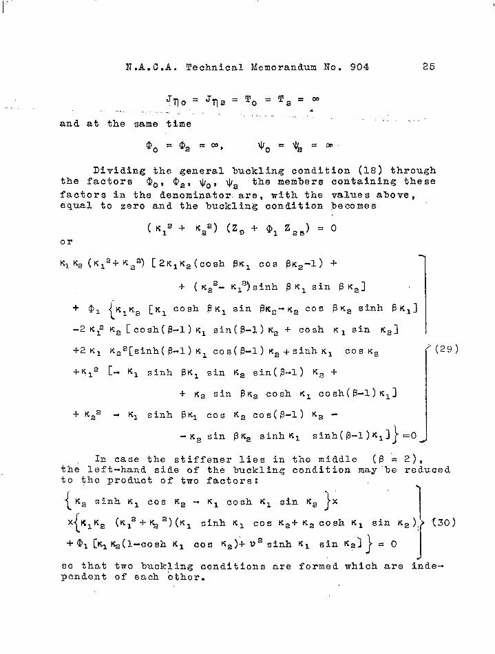
??lo =Jqa=To=Ta=~,.. .. . .,., ,.,, .
,,,.and at the same time
... .,
Dividing the general buckling condition (18) throughthe factors O., 02, ~o, $2 the members containing these
factors in the denominator are, with the values above,equal to zero and the buckling condition ,becomes
(lCl’ + Ka’) (Zg +- (DI z,,) = oor
-F-2K1 K22[sinh(13_l) KI cos(f3-1) ~2i-sinh~l Cos K’ ((29)
- K2 sin 13K2 sinh K1 sinh(13-l)KI]~=0 JIn case the stiffener lies in the middle (i3=2)*
the le~t--hand sj.de of the buckling condi.ti.on may”be reduced
to the product of two factors:
{ ~2 }“sinh K1 cos K2 - Itl cosh KI sin K2 X
1
{t (30)X K1K2 (K12+~2)(Kl sinh KI cos K2+K2cosh KI sin Ka){/
+@l [ttl~(l-cosh ‘1 cos Ka)+ V2 sinh K1 sin K’]}
=0I
J
so that two buckling conditions are formed which are inde-pendent of each other.

26 N.A..G.A. Technical Memorandum No. 904,.
1. The buckling “condition which is formed by put-ting the first factor in (3o) equal to” ,zero:
K2 sinh K1 cos ~ - 1$1 cosh K1 sin Ka = O (31)
is independent of @l, and agrees with the bucklingcondition for a plate of the width b/2, whose one lon-gitudinal border is hinged, the other one being fixed(reference 8). The corresponding %ucklin~ form con-tains therefore a nodal line at the stiffener. The nod-al line is identical with hinged mounting of the plateat the same point (antisyxnrimtz-ical l)uckling with respectto the axis n= 1).
2. By placing the second factor i.n (30) equal tozero, the buckling condition
(32)
is formed, which gives the buckling stresses of plateand stiffener (symmetrical lmckling with respect to theaxis n = 1). To the limiting case @l.= O correspondsthe nonstiffened plate fixed at the borders O = O andT 2;= the corresponding buckling condition lecomes:
Kz sinh KI cos K2 ~ K2 cosh K1 sin K.s= O (33)
from equation (32), reference. 8.
In figure 8 the’lmckling values k are plottedagainst the ratio a. A comparison with the correspond-ing’ bucklinq curves for hinged longitudinal %orders shows

N.A..C.A. Technical Memorandum No. 904 27
(reference 14) that the antisymmetrical buckling form\ with built-in borders is already determining for consid-
erably smaller values of y than for hinged longitudinalborders (reference 19).
Plate with two longitudinal stiffeners:4b _ —————-———
a) General %uckling condition.- The investigation--—--— —.—--.—. ———._————of.the rectangular plate with two longitudinal stiffeners(r = 3) is limited to the case of all four borders hinged.
We have
To =T3=0, YO=Y3=CU
and therefore,

~8 N. A.C.A. TechnicalMemorandum No. 904 =ble 3
-
LI
2
3
4
“5
6
7
8
,9
f
I,10
r
;1I
1
r,12
(II”)
— .
(10”)
- so that the boundary conditions (8’) to ‘(11s) simplifyto
Yl=o, (9”) Y3=0, (II”)y;’= c), (8”) y:=o (10”)
The transitional condi%lons between the fields 1 and 2are the same as for the plate with one stiffener (tablel); corresponding equations are obtained for stiffener 2.The 4 boundary and 2x4 transitional conditions form,with the solutions:
WI = Ylsinv&, Yl=Al@ifixl~+BIQO~~q+ Clsinzzq+D;cosxzq2 2 2 2s 3 8 3 : 3 3
the d.efiominator determinant, shown in table 3, fromwhich the buckling condition is obtained by putting itequal to zero.
!l!hesolution of the determinant is briefly given inthe foZlowing: After eliminating the lines 1 and 2, thedeterminant beoomes
(34)
1*2The subdetermtnant b d becomes, after elimination ofs
the lines 11 and 12,

Tablo 3(conto) “M.A.C.A. TechnicalMemorandumXo. 804
~. i k
Ic:,.. . .—.-. .. .
I
I— sin%,
+ L:sin %, +“‘+%: Cos %, I
+ xlsinxi I— X* Cos%,
bl + b.—silt - %, –cm * x,6 1
bl+ b,‘X1 ‘t” bl % –x,cos+x,l+x,.skl~x,
-~.cos~-p —x, +ti.six+%,
b I bsin — x,b, Cos— x,bl
Since the lines 11 and 12 are independent of the lines3 to 6, the four 8-line subdetermi~ants in (35) withr = i,k and s = t,m (r+ 8) may be written, aftereliminating first the lines 3 and 4, as
~he nine subdetermtnaats oeazrzing in.this equation be-come’, after elim$nathg tho lanes 5 and 6,

30 M.A.C.A. Technical Memorandum No. 904
Substituting these terms in the subdeterminant (36), weobtain, after arranging tb.e equation:
The ce.lculation of the sabdeterminants of fourth orderon the right-hand side gives, for the various values ofr and s, the following equat ions:
r=i, S=l:
3,4*596— — %2(%; + x:)Qsof *bl + b%
a,c, e,f —xl COST X21
1
3, 4, 5, 6a, c, f, h [
= (x; +X:) –~x2(x; +x:)+
+ @2 (X2 Ginbl + b,!&p xl Qf ~ bl + b, bl + b,
%—%sin~ X2Cos—1 1 1 )1bl ‘2 ‘
3>4, 5>6 bl + ba bl + b2—+sin T= — Xl (~; + @ @2~”f b X21
a,. c, e, f . 1 1

11.A.C.A. Technical Memorandum Ho. 904 31
3, 4, 5. 6!u, c, t, gl=o’
3,4,516_ bl + bi—x2(x~+@@2G3inzr ~,
a, c, ~, h L
, , ,.,,,,,, 1. ■--..

““32 N.A. C.A. Technical Memorandum No. 904
placing this determinant equal to zero.
b) &Q stiffeners being symmetrical_lQ_~h~_~~Qi~—-—-- —— 4..————.— -—line =n b~~&. with eciual dimensions.- For two stiffen”---.——ers %eing symmetrical to the middle ’11=?)/2bl with equal
cross sections and moments of inertia, @l %ecomes
so that the left-hand side of. the buckling condition (38)can be simplified with these values and can be written asa product of two factors. With b/bl = ~, the bucklingcondition bebomes
‘{-K1K2 (q 2 + ICa2) sinh PK1 sin BK2
+ @l [- K1 sinh BK1
1
sin K~ sin (B - 1) ~~+
-1-K= sin ~ K2 sinh K1 sinh (B - 1) Kl]}.
xiKIK2 (K12 ~ Ka2) cosh i3Kl COS 13K2
~ @l [Kl cosh B KI sin Ka cos(p - l)Ka -
u Ka COS P K2}
sinh Kl cosh(p - 1) Kl] = O
Since each factor, placed equal to zero, satisfies theequation, we get
1.- .- KIKa (K12 ~ K22) sinh PK1 sin 13K2
-!-@l”[- KI sinh P Kl sin K2 sin (~-1) K2~
~ Ka sin @ K2 sinh K~ sinh (p-l) K1 j= O1
This buckling condition agrees with one for a plate ofwidth b/2, hinged at the longitudinal borders, whichstiffened ‘by a longitudinal stiffener at a distance I’1(See buckling condition (19), p. 14. ) At the point ‘fl
(39)
*
(40)
theis= 1.=
6/2 , therefore, the boundary ~onditions for hinged mount-ing are satisfied. Thus the %uckling form for our casewith two stiffeners in the middle of the plate contains anodal line. The buckling condition (40) therefore givesthe buckling stresses for buckling antisymmetrical to thecenter line l-l= $/2.
N.A. C.A~ Technical Memorandum No. 904
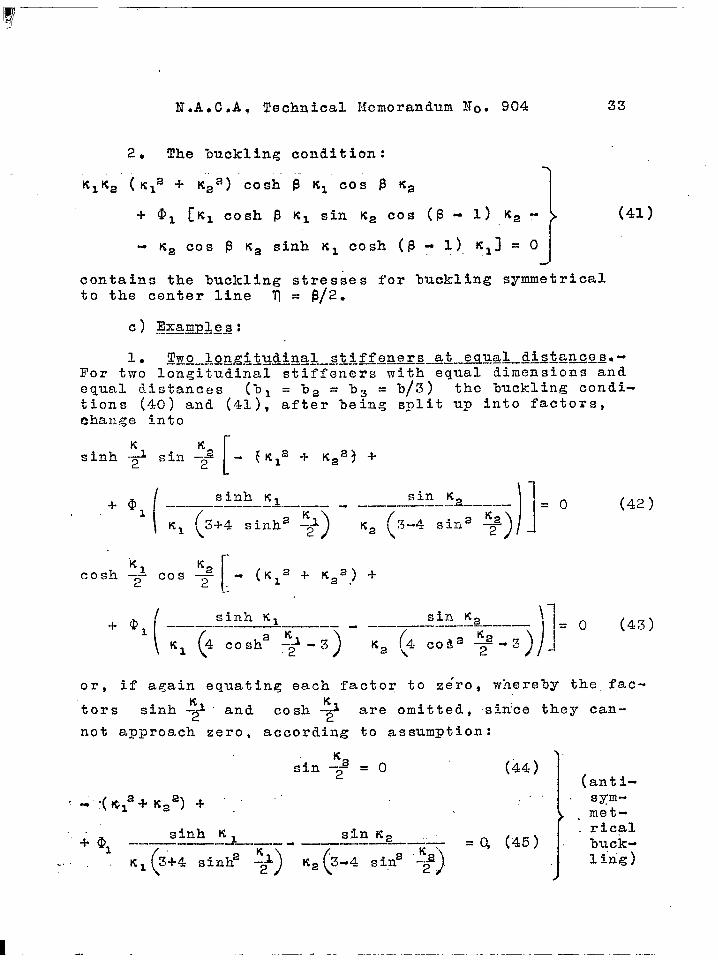
2. !I!hebuckling condition:.
K1K2 (K12 -+ IC22) cosh ~ KI COS @ K2 1
33
(41)
contains the buckling stresses for buckling symmetricalto the center line ‘II= $/2.
c) l!xamples:——.— ———
1. Two longitudinal stiffeners aj_9qQQA&&Q2QQS.-13’or two longitudinal stiffeners with equal dimensions and
equal distances (bl = b2 = b3 = b/3) the buckliwz Condi-
tions (40) and (41), after being split up i,nto factors,
.ohange into
[
sinh K1.
+ 01 .——— ——..————.-—— - . ‘l!?-?.a–____—— ——
( )1=0
‘1 3-I-4sinh2 ~2A) ‘2 (’-4 ‘in2 W
(42 )
“K ~.!?
rcosh -A COS —— - (Kla -?-K22) ~
2 2. .-
(( sinh K1 sin K2 \.-1-01 —-——- .—-- ———— - ————————————— =
) ))1
(43)
4 cosh2 :2a~1
-3 (4 Coa= +-3K2 \
or,#
if again equating each factor to zero, whereby the fact-
ors sinh -$# and cosh ~ are omitted, sin’ce they can-
not approach zero, according to assumption:
‘2sin -- = O2
(44)
1 (anti-
“: “(&Z2~K2a) -k ““
1“
.“. sym--, met.-
.‘+@l
sinh KI s,inK2 rical—— ————— —- . buck-
.,.,K1 (’
3-t-4sinh2%) ~T=-=~% = Q ‘“) 1’”)
1 4. .-
... .,’: ...... ...!,.,.
N.A. C .A. Technical Memorandum No. 90434,,
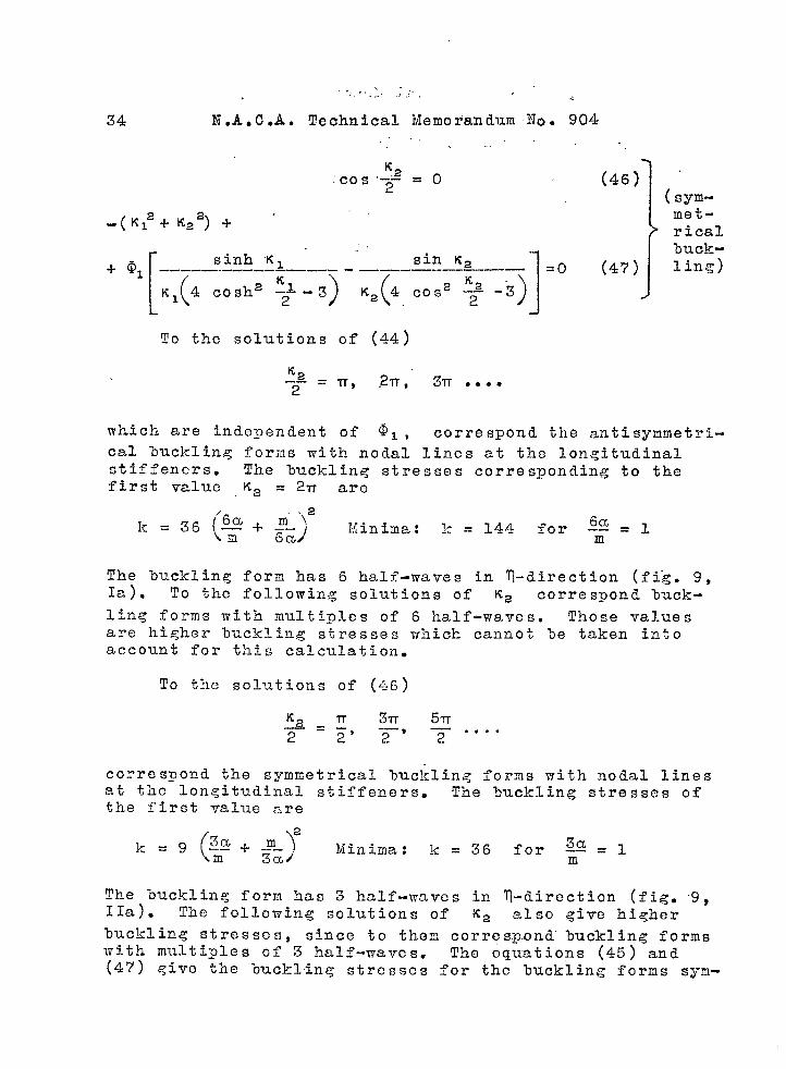
(46]”?2:-?0s–- =2°
-( K,%tt22) -1- ‘
+ q
[
sinh K1 sin Ka--—-—.-.-——- —.——— . —..—————— —
(4 cosh2 :22
) (.‘2
~1 -3 ‘2 4 COS2 –2– -3)
To the solutions of (44)
~2—-2
= IT, ,2T7, 31T ● ,**
=0 (47)
.
(:%:
ricall)uck-ling)
which are indepe~den~ of ~1 , correspond the antis ymme%ri -cal buckling forin~ with nodal lines at the longitudinalstiffeners. The buckling stresses corresponding to thefirst value ‘2 = 2Tf are
The buckling form has 6 half-waves in ?l-direction (fi”g. 9,Is). To the following solutions of Ka correspond %uck-lin,g forms with multiples of 6 half-waves. Those valuesare hi,?her buckling stresses which cannot 3e taken intoaccount for this calculation.
TO the solutions of (~~)
~a=~ 3-R 5Tr——2 2’ 2—’ 7“”””
correspond the symmetrical %uc~<ling forms with nodal linesat the longitudinal stiffeners. The buckling stresses ofthe first value are
k= 9 (;!2 + J!!-~2 Minima: ~3a/ =36 for@=l
The buckling form has 3 half-waves in q-direction (fig. 9,IIa). The following solutions of K2 also give higherbuckling stresses, since to them corros.p.ond buckling formswith multiyles of 3 half-waves. The 6quations (45) and(47) give the lnzcklinq stresses for the buckling forms sym-

1? ‘—” ‘“,.Z
N. Jl.C.A. Technical Memorandum No.
metrical, and antj.symmetrical to the axis r. -. whichthe plate buckleij with the stiffeners
and IIb).
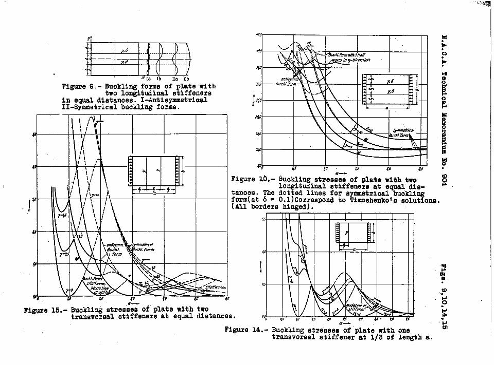
In figure lo”the.ljucklinjg ~tresses for
35904
= p/2, at(figo 9, Ib
Y = 5 and 10are plotted against the ratio “CL. For small ratiOS” (a c: 0.4) the buckling condition (46) gives the smallestbuckling stresses, for great ra~ios the buckling valueshave to be calculated from (47). Besides that, for smallvalues of y (in fig. 10, for Y = 5) at ratios a = 0.4to 0.7 the antisymmetrical buckling is calculated from (45).
Timoshenko calculated approximate values for this caseusing the energy method and put them together in a table(reference 20), but the table is set up only for the sym-metrical buckling cases according to (46) and (47), not forthe antisymmetrical Wckling form from (45). Several nu-merical values in the table are therefore too great. For acomparison in figure 10, the” curves for y = 5 and Y =10, respectively, and 8 = 0.1, which correspond to Timo-shenko !S values, are’ shown as dotted lines. The values ofthe approximate solution are slightly greater than the ex~act values from (47); however, with increasing ratio asthe differences hecor~e smaller. The solutions by Lokshin(reference 13) are also incomplete as they only considersymmetrical buckling.
2. Stiffeners at small distances sYmmQ3x&gQ~_&Q_j~f2center line.- With welded structures the case. may occur————— ______where one longitudinal stiffener is split up in two, eachhalf being on a different side of the plate but %oth at asmall distance from each other (fig. 11) , in order to avoidlapping of the welding seams. The buckling stresses can becalculated from (40) and (41) if both halves of the stiff-ener are symmetrical to the middle. Since ba ,is smallagainst b by hypothesis, the buckling stresses for a,nfii-symmetrical buckling (fig. 11,1) increase as “D~ increases;for, in the limiting cases ba = O, the plate buckles likethe nonstiff.ened plate with a nodal l.inp.,,whereas at an ec-centricity ba. also the stiffeners are bent and thcroforethe resistance aqaingt Inzcklin.gais greater.., The. bucklingstresses therefore remain on the safe side. i.f tho.se,.of thelimiting case ha = O are used. However, the bucklingstresses for symmetrical huclkli.ng (fig- 11,11) decrease asba increases. For the exampze of the, plate with the ratioa= 1, and the stiffener With Y =2.5 (6 =0), the buck-ling Yalues are, from (41)

36 “ “’N.A. C.A. Technical Memorandum No. 904
-~.:-t-;~+-:::;fi:=ti%
The differences between the k values are small, so thatif no qreater eccentricities are invalues of the limiting case ba = O
III. l?LATll‘WITH TRANSVERSAL
question, the lmcklingcan be used.
ST13’IU3NERS
1. General pri:~cipl~&.- The rectanguln,r plate withtransversal stiffeners at the points x = al, X = al ~
.a~ ..* (fig. 12) consists of r plate fields with the ra-
tios
(c+= ratio of the whole plate).
With the notations
the deflections w of the center cross section of eachplate field i, on account of the compression stresses atthe transversal borders ~ = o and g = a, satisfy thedifferential equation (2), in which the value CPl is to
be re~l.aced 3Y p, ac~ording to the notations mentionedabove.
Assuming hinged (w = dw = O) longitudinal hordersn = Cl and ‘n=l, the differential equation (2) in eachfield i is satisfied by
TVi ‘xi(t) sin ni, m T (ni = 1,2$3 . ..) (48)
3Y which the bending area in ‘&direction is assumed tohave sine shape. The function Xi, only dependent on ~,
is obtained from the common differential equation
~IVi
~ (llz~ - 2ni2 TT2) ‘iii ~ ni4 n4 ‘i = 0 (49)

N.A.C.A. Technical Memorandum No. 904 37
the general solution of whioh isF,. . .,, ... ,.>.,.., ., .,,,
Xi=Ai sin ~iAl+Bi cos fi~l+Ci sin ~i~a+~i- cos ~ih= (50)
Since for every field according to (48] there exists asine-shaped (in ~-dlrecti.on} bending area, the number ofhalf-waves in n-direction must be the same in all fields(ni = n) because of the steady connection of two adjoin-ing fields. Of all values n the minimum values of thebuckling stresses correspond to n = 1; therefore, thefollowing general de~ia~ions are calculated with n = 1.With the aid of ~he four boundary conditions at the borders
t t and the
gene~u-a~~uat~!~~- 1 )
4(r - 1) transitional condi-ti~ns at tbe stiffener we can set up 4r homo-.,“ ., from which the buckling condition, andfrom t’hat the lmcl:ling stresses ok =koelated.
can be calcu-
2. Sciundar-z transitional coridztlons.- At the hor-_.z:Wl_. _L_:.__________.9--:___--—-.—__...tiers t = o arid ~=a, rigid and hinged mounting i“sas-sumed; therefore, for = OE
,T?l =0 (51)
4W1 = o (!52]and for “[=a
‘r = o (53)
Awr = O (54),.
At each stiffener i, iSeo S for f.= al+ a2~.Qo0 ~ ~ai[i~l to (r .-l)], the follotvlng ”transitional con-
ditions must he satisfied:
1. The geometrical conditions for steadiness require
Ivi = Tvi+.’$ (55)
(56)

1 IImI ,,mm 1111 I 1111. I IIS. s---- s S. ,, ,—--. —...... ....--—.... -—. .— ....—..-
1
. .,.,
38 N.A. O.A. Technical i~emorandum No. 90”4
2. Neglecting the torsional stiffness of the stiffen-ers, the “oending moments m~ of adjoining plate fields i
and i ~ 1 at the stiffener i are equal, i.e.
Since on account of the steady tonne-ction the curvatures inm-direction at the stiffener must be equal, i.eo,
equation (57a) changes into
(57%)
(57)
3. Considering the plate fields i and i-t-las
cut off along the stiffener i, the transversal loadingof the stiffener must be put equal to the difference ofthe reaction ~orces of the two plate fields, at whic~ thedeflections of the stiffener Iiust he assuned to be equalto the deflections i or i-l-l at the point t =(X1+
a~~ ...~~i. Denoting the moment of inertia of the stiff-
ener about the ~-axis by Ji, me have the equation :
. .
EJ.or with ‘=Yi~: and, considering (56) and. (5’7%)
~ a~vri ~3W i ~3Wi~~——-.i
———— .a~z =
——— —...—ag= a~3
(58a)
(58)
.. After substituting the solutions
in the boundary and transitional conditions, we obtain thefollowing equations, only dependent on the variable ~ ,

N.A. CiA. Technical Memorandum No. 904
for determining the constants in the functiohs xi :,> ... ..,.. .
‘% : *ox, }for t 0- “--”-”=
Xr=oX’l=O ) for ,5 =ar
39
(51’)(52 f)
(p?~)
(54!)
(55 ‘)
(56’)
(57’)
(58t)
trans-versal stiffener (r = 2) eight homogeneous equations, ac-cording to (51!) to (58!), arise from the solutions offields 1 and 2.
\the coefficients of which are given in table 4. This de-nominator determj.nant iS solved as for a longitudinal
stiffener; therefore we omit the whole process of solution
for table 4. The result of the solution gives the buck-ling condition for the uniformly compressed plate with onetransversal stiffener: ,. .’
i:(59)
+ A2 sin a Aa sin alAl sin ti2Xl) =’0‘J,,.
The buckling conditions for infinite stiffness Y,i.e., for knife-edge mounting at the stiffener, resultfrom (59) by placi,ng the factor Y equal,to O. !lhe buck-ling”condition is
I

40 N.A. C.A. Technical Memorandum No 904. .
- Al sin a Al sin CLIAz sin asA2 ~(60)
~ Aa sin cc Xa sin al~l sin ~Xl = O
Buckling conditions (59) and (60) are, regardless ofthe position of the stiffener and the magnitude of thestiffness Y, satisfied, if at the same time
sin a Al = O, sin a A2 = O
or
~ Al =mln
a A2 =m2-fr
The corresponding ratiostained from
1=a
They are
6 =~ml ma,————
(ml = 0,1,2,3 .-.)
(m2 = 0,1,2,3 ...)
a and buckling stresses are ,0%-
~L = _ka--mln man
(ma + ma)aG= .—..—.—.
ml mz
The case ml or mz equal to ~ero cancels, as we
would get ;=0 and G = co. With ml =m2 =1,2,3 ...z becomes
E= 1,2,3 ... and E=4
This case also has to be excluded since %y hypothesisk~4. The values k = 4 for the ratios a = 1,2,3. .s’0are the buckling values of the hinged, nonstiffened platewhere t~he ?mckling form consists of square buckles. It isevident that with one transversal stiffener present, thebuckling values, on account of the greater resistance, gen-erally must lo greater than the ones of the nonstiffenedplate. Only for the special case, where the stiffener co-incides v~ith a nodal line of the buckling form of the non-stiffened plate, the solution ml = m2 with k = 4 is
valid also for the stiffened plate.
!l?heother values =, ~ yith ml, m2 = 1,2,3 ...’ (m, +
m2) have a simple significance for the nonstiffened plate.

--’w
Table 4
g h.d e
D1 A,
f
c, 1. Q
1’ i I(51’) I
I
I ,.(52’)2
(55’)3
ii
iis1?●
z..
(57’)4—
5—
6
—
7
i
(56’)
(58’) —ajcos Qa, +~sma12,
—
sina~ cos “a&(53’)
(54’)

42 N.A. C.A. Technical Memorandum No. 904
Plotting the Imckling values k as functions of the ratioa, the points ~, ~ agree with the coordinates of theintersections of the ?mckling curves k = k(a) for thenonstiffened plate which luckles in longitudinal directionwith ml and ma half-waves, as is olvious from equation
The result may be summed up in the following sentence:At the points of intersection of the buckling curves forthe nonstiffened plate for ml and ma ‘half-waves in
longitudinal direction (ml, ma = 1,2,3 ●**; ml+ m2)*
the buckling condition of the plate, stiffened ly one trans--versal stiffener at any place and with any stiffness y
(also with Y = m) is at the same time satisfied.
For the restriction, ratio aJ% “oeing a real frac-
tion, we can place
in which r, s and u=r~s are positive integers.
the “oucklinq condition (59) becomes
Each term on the left-hand side contains the common factors
sin ~lt and sin X21, so that (61) may %e split up into
sin AI1 =0, sin h2t =0 (62)
and

—
N.A. C.A. Technical Menoranclum. l!oq 904 43
(Ala - ?@ A~h~sin u~’” sin u Ad—— - ...——“sin Alt sin Aa’.“ ..-,–-,.. ,-----... .. ,,-.,.
+Y~4.[
sin u-h ‘ sin r ~2’ sin s Ad ~- )i~-— —+-–-—sin ~2f
-—-——-—
\
(63)sin hi
,.,sin-u A;’ sin r Alt sin s Xlf
+ Aa -—-—— 3- —- —----— --------
~ .J
= osin Aa sin A It
The quotients in the last equation are related terms.
The buckling conditions (62)’ which are independent ofY, are satisfied for Al’ = ~2t =17, 21T, 31T,00S mm ● BO
Thy corresponding %uckling values are, both for Al’ and*
Since c .?=%—s—‘ the fields 1 and 2 buckle like plates
hinged at the four borders with mr and ms half-wavesin longitudinal directfon, so that the entire plate buck-les with m(r ~ s) half-waves and has a nodal line at thestiffener. According to luckling condition (63) plat~ andstiffener buckle at the same time.
Transversal stiffener at a distance al = a/3(al =1:/4).
a) Buckling stres~es Lincluding the higher ones) for-.—-_—_ ___.___b_- ___ -the square relate——___ - For the example of the square plate—————____ .mith one transversal Stiffener at one-third of the lengtha t~e buckling stresses from (62) and (63) are plottedagainst.’Y in figure 13. In the buckling conditions wehave to place
.,’,
The poin.ts’of intersection of the curves( 63) withthe 1$-axis are at th”e same time the buckling stresses ofthe nonstiffened plate (y = O); the corresponding lmck-ling values are: . ..

44 N.A. C.A. Technical Memorandum N.0.,,904
k=4 (%ucklin~ fo~rn: 1 ~alf-wave in longitudinaldirection)
k= 6.25 “(%ucklinq, form: 2 halffiwa’ves in longitudinaldirection) ‘..
k = 18.06 (buckling form: 4 half-waves in longitudinal., direction)
,,
With increasing Y, the lmckling stress k = 4 (~ =
O) goes up first and approaches then asymptotically thevalue k = 5~’795, to which corresponds accordingly astiffener with infin,ite stiffness. With k = 5.795, wehave reached the greatest, in practical. cases occurring,buckling value: the curves above contain higher buckling
stresses. To the values 5.V95 c k< 6*5 correspond neg-
ative values V. These %uckling stresses are without phys-
ical significance since there are only positive ratios 3e-
tween bending stiffnesses of the stiffener and plate.
(64) lve o%tain the further solutions:
From
(2
Al’= A2’=IT, ‘2?T*.. with k = )3m-1-~1~ (m=l,2.. .)
The minimum value occurs for m = 1 and is k = l.QQ =9
11,11 .*.. At this value” the plate buckles with 3 half-Waves in ~-direction tvith a node at the stiffener.
~) Bucklinp stresses demending oq_JJ&_YE_~SQ__._aJ- In
figure 14 the buckling values are plotted as functions ofal for the case of one transversal stiffener at a/3.
buckling conditions (62) and (63) are for this case
The ‘oucklinq values
The
(64)
(65)
(’2
k=~;~–~3m )
(m =1,2 . ..)

—
f
N.A. C.A. Technical Memorandum No. 904 45
from (64), which are independent of Y, are those of thenonstiffened ,plate-with 3,..6, ‘9.....half~waves in longi-tudinal direction, so that a nodal line occurs at thestiffener.
The solutions of the equation (65) give curves thatare calculated for ‘Y = 0.5, 1.0, and and plotted infigure 14. These curves coming from in~inity with a = Ohave a wave-shaped course and approach - not mentioningthose for higher buckling stresses - with increasing ratioa asymptotically the minimum value of the %uckling stress-es k = 4.
For the ratios a = 3, 6,’”9 ... and those in the imme-diate nei.gh%orhood, the, buckling condition (64) gives thesmallest “ouckling stresses.
The initial and end points of the sections, withinwhich according to (64) lie the smaller buckling values,are” qiven by the intersections of the curves for (64) withthose for (65), the magnitude of these sections being de-pendent on the magnitude of the stiffness Y. The sectionsare smallest for Y, = O; tho corresponding ratios a thenlie within the limits
~(3m - l)3mCa< ~3m (3m -1-1)
(For m = 1, CL is 2.450 e a < 3.464.) The sections becomelarger with increasing Y and reach their maxima for y =CO. (For m = 1, we got 2,12 < a < 3,68.)
Buckling condition (65) is satisfied independently ofY, if at the same time
4 COS2 ;A1--l = O and 4 cos2~ A2 - 1 = O
or
Cos :,Al=:$ and Cos ;,A2.=* $
so that
These. values are reached at the intersections of the buck-liq~ curves for ml and “ma half-wa:es of the nonstiff-
ened plate(
————~ =~til.m2, I = &W!!2al_
) with ml, m2 =
1, 2, 4, 5, 7, 8 ... (ml+ ma). ‘1 ‘2

46 N.A. G.A. Techn~c,a,l Memorandum, No. ,904
AS Figure 14 shows,, the ,curves (65 ), depending on ~,touch each other. at th,et,in,te,rsection,sof the ‘Ducklingcurves for 1 and 2S 2 and 4, 4 and 5, etc..,half-waves ofthe nonstiffened plate, so that in these points the 3uck-ling values k are equal to those of the nonst’iffenedplate for any value of the stiffness y.
From table 5 the exact luckling values k “for the ra-tios al/a = l/3 and al/a = 1/4 may be taken,
—.—..——-
aJa
1/3
——.——.
1/4
.—. —-
Table 5———_.=______ ——..————————._.—.——__—————-———~——.————..——————
7 a...——————..—————.-.——-.O*4 0.6 i 1.0-—.-——-———.———————
t
_A_—___ __——————-K“ 11;265 8.703 5.69410 13.768 10i085
4
5:748
15 ~5.840 10.741 5.764—————.——————————————.—— ———-.————-5 10.287 ‘7,474 5*317
10 11.90’7 8.655 5.40215 13.210 9C2p6 i
————————————————————— l_-EE.-
.———————-1*4
.—— ——--— —.
4:5194.5194.519.————— ——-4;5154.5164.516
—————-
———.—————1.8————..——44:3174.3264; 329
4:4584.4724.477
2. Transversal stiffener in the middle of the~l@ti.-------------------------------------------------------l?or a transversal stiffener in the middle of the plate
(al = a. = ~/2) the buckling conditions (62) and (63)
than.qe into
“=(2%+%$‘m=’32y30D0)are those of the nonstiffcned plate with one nodal line inthe middle. The corresponding buckling form therefore isanti symmetrical to the center line ~ = a/2. Buckling con-dition (67) which is also contained in Lokshinrs solutions(reference 13) gives the Imcklinq values for the bucklingform which is symmetrical to the center line ~ = a/2. Therequired minimum stiffnesses were calculated by Timoshenko(reference 2 ) with the energy method.
. . .

I!!j-,,,
N.ik.C.A. TechnicalMemorandumNo? ~4 47”4. PULte wit h two transvers al stiffeners
a) genera ~.- ‘~or thz platewith two transversal stiffener= the 12 equations in table6.are daveloped..from.the. deflect@ns., w of,t.hq Platefield 1 to 3 with the atd of the boundary and transi=tional conditions (51~) to (58s). l!he solution of thedenominator determinant gl~es the following generalbuckling. condition of the hinged rectangular plate withtwo transversal stiffeners:
“Z)2sin a 11 sin a ;.2i.;i.:(;.;- /.2
P) f. [i,sin a 21 sin al ;.2 sin (a2 + %3) J2+n41.~7.2(j.:— q (/1 .1 .
— /.2sm a ;.2sin al ;.lsin (a2 + X3) 21]
+ 72 [;.lsin a.~.lsin (zl -i a2) ;.zsina3;.2 ,.– ).2sina 12sin(al+ a2)jlcsina3ii]}
L 78 ~1 ~z {~; sin a Z1 sin al 22. sin a2 >2 sina3A1. , (68)+ l;sin a22 sin al ;.1sin a2 & sin ~ Z1
+ 21& [sin al ;q sin q 1.2(sin al 22 sin a3 11 —
— sin (al + a2) 22sin(a2+ a3) 71)+ sin al 1.2sin a3 ?I (sin al j.1sin a3 ?.2—
— sin (al + a2) ;I sin(a2+ a3)7.2)]}= O.
b) Two transversal stif~en r metr al jo the___~~& with equ%s;i~=sion~~- The lnxck-center line
ling condition (68), with stiffeners placed symmetric-ally
Yl= 72=7 and al=a=, al=aa
)1 I+yn4(—?q cos~?.lsin al~2cus+~2+~2cos~~2sina1)~cos+-~1’=0.
From this we obtain two different buckling conditionsby placing each of the tw~ factors equal to %ero.
i. The first “buckling cond~tion‘1 sin~).2
1 (70)(1-~)~l~tifl~ 1
+y#(–~sin ~21sin%”12sin~&+12 Sin~~2sinalksin~ 4)=0 [
agrees with the one for the plate with one transversa~stiffener ,at the point ~ = al (see equation (59))where the border of the plate ~ = u in (59] correspondsto the center of the plate E =-a/2 in (70). Since
%uckling condition (59) is based on hinged plate borders,We bu,ckling,form from (70) uontains one nodal lime inthe center of the plate, so that the ant$symmetricalbuckling forms correspond to buckling condition (70).
2. The secondf actor in (69) gives the bucklingcondition(if– 1;)2122cos~ ~ cos~ 12
I (71)+y.+(—~cos~l~sina122cos~2z+lzCos~~.2Sina111Cos~%1)=0 I
with th6 buckli”hg stresses for buckling Yorms symmetri-cal to the center line ~ = a/2.
40-
I
—
2
—
3—
4
5
6
—7
—8
—
9
IO
II
12
IT.A.C.A. Technic81)CemorandumNo. 904
la “ ‘c ““d.
e IfG1. Al B1 c1 D1 A, B*
(51’) I r— ,.—._..--------- - ——(52’) a: ~:— —.—
(55’) sinalal cosal& sinal 23 Ws al a, — sin al Al — cos al Al
(57’) — a?sin a, A — A:cos % 4 —% ‘in al 2* — ~: Cosal a% +~sinal~ + A~,COSal~
,-
(56’) ~ cos al.4 — Al sin q Al Az cos al h — A% sin al Az —~cosc41& + Al sin al ~— . — .
(58’)A; cos al Al — A: sin al 21 A;ax al& —A:sinal&. — A:cos al lq
+Y13T4sin U1h -l-,YlW4cos al 4 +71 n’ sin% A + yln’cosalA+ 1: sin al 11
(55’) sin (al + az) Al cos (al + a,) Al1- -––
— l? sin (al+ az) Al — 1; cos (al+ aJ iq;74– _.. ——(56’) 21cos (al + uZjal —&sin (al + aJ ),
._ — —
k?cos (al + a2) & — A; sin (al+ a2))1(58’)
+ hn4sin (al + ai) A +Yi Z4CoS(“l +@ A—
(53’). ——— ..— — . —
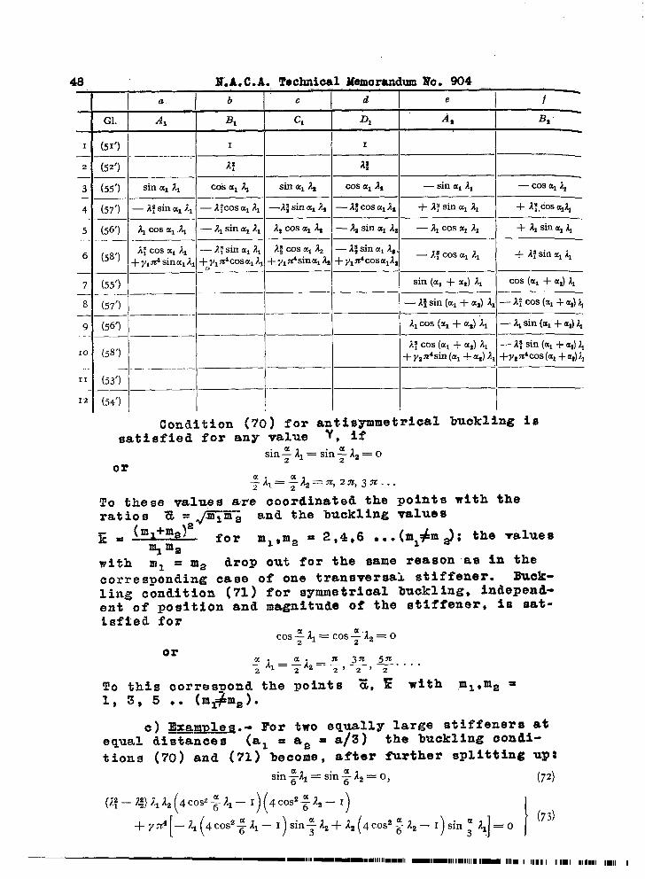
(54’)
Condition (7o) for afti:~etrica~ buckling issatisfied for any value ,
sin~Al=sin~l%=Oor
~h=~a2=%2n,Jn...
To these values are coordinated the poitits with the~@K%ratios Z = and the buckling values
E=(ml+m~)
for ml~ma = 2 ,4,6 .*. (mi#m ~; the ~alues~ ma
with ml = m= drop out for the same reason as in the
corresponding case of one transversal stiffener. Buek-
lin.g cond.itaon (71) for symmetrical buckling, independ-ent of position and magnitude of the stiffener, is sat-isfted for
COS:11=COS;”12=0or
;a1=:a2=:,$,y . ...
To this correspond the points E, ~ with .ml,ma =1, 3, 5 .. (ml#ma).
c) ~xamvleq.~ For two equally large stiffeners atequal distances (al = aa = a/3) the buckling condi-
tions (70) and (71) become, after further splitting up;
sin~ll=sin~lz= O, (72)
(1;–(@ ~~& 4cOSz-;-al— I)(
4cos2;@r
+y~4[–~1(4cos2;11 –1) sin~l,+!2(4cos2~22-l) sin~,nj=o I ‘“)
—— lm-,lE -11-mImlmllll Ilmmllll -ml-Ill 11111IIIn mm Ill 11 I II II I I I m I II 111111111111 I
M.A.C.A. TechnicilMemorandumJio.904. .49
h’ i i ~ ‘“k” ‘““ )))
c%” I ~a .-/3. 13= c, “ 1%
‘“+ ‘: ,“ ““ “
.——. ..........——.. — ..-—...,..—.—._——--.--..=--..— .-.-—..—. ..—.
1,.
——.— —.——. _______ ..-.-— - 3----.-........———— Sinml2* - aasal&
-— .-—, — —z- .— ——..—.+ ~:sina,A* + G Cosal2,
.— ,—-— —__ -—______ .-——.-—......-— .— AZCosa,a, ~ a,‘sillala,
—.—-...—--—- .......-______........—. .... ._.___ .- .-— _—-.—
— 1;COsa,a, -t4 SinalA,—— ____ ..__ -..
~in(a,,,+a,)2, cOs(al+ a,)aa — sin(a,+ a,)Al
“’ “~
— cos(a,+ a,)Al— sin(a,+ a,)&— cc>s(al+-a,)Az—’ ..._—..—.- ~sin(~,~ fx,)~,— ~~cOs(a,+ a,)l,+ L;sin(al + a,)Al + Atcos (al + a,) A, +* sin (al +aJAi + Ii m (al-l-a,)A——
Itcos(al + ai) AS — Aasin (a, + a,)A% — Al cos (al+ a,) Al + Alsin (al +a,) Al —2,cos(a1 +aJ 19+ Assin(al +ai) A8,—.. .— .—-. ..—:
~ cos (a, + a,) A, —N sin (al + a,) A,— Jfcos (al +a,) ?V + Afsin (al i-a,) 11+y,n4sin(ai + &8)La +y,n4cos(a1+aJ A,
—A!jcos (a, +ai) La + ~sin (al +a,) h
—— .—...— — —.. - ..—.,. . . . — ...-.. — ._. _ - .——.
sin a-21 cos a Al sin a A,
“7
Cos a as—.—--.—- ...-..—-._ —_..__... ___ .. . ———
A! sin a Al Al cos a Al ~sin a As x; C(H a a,
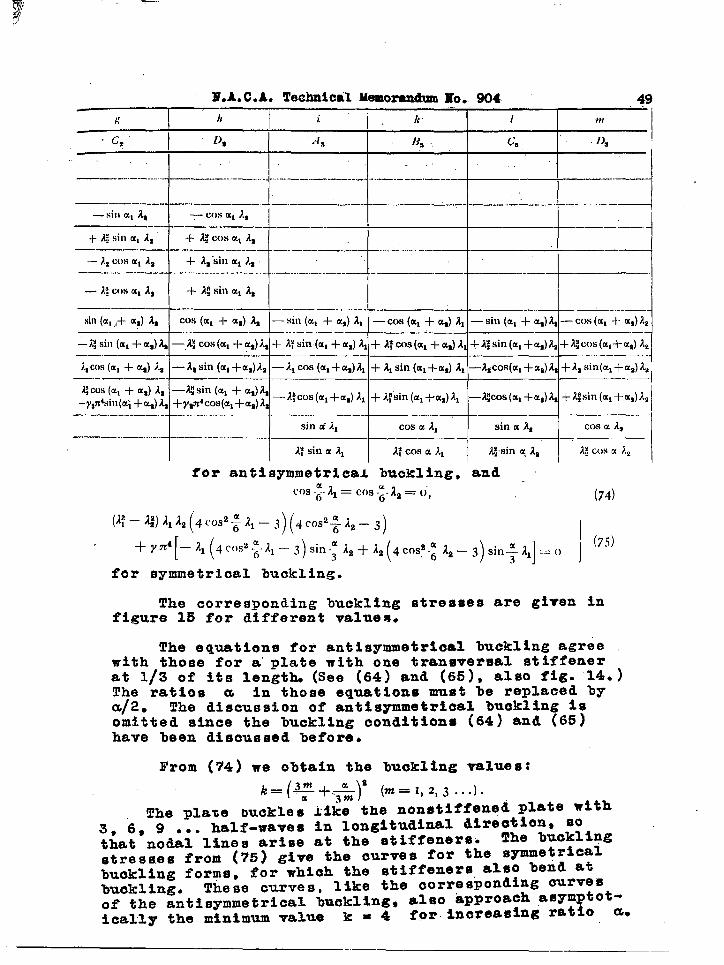
for antisymmetrical buckling, andcm .;. 21 = Cos -;. 12 = (;, (74)
( )((1; –2:)1,22 @sa&l-j 4cos’; &-3)
[( ) ) 3,1
(75)+Y7C4 –11 4C(M2~-11-3 sin-f&+12( 4cosa~ 22–3 sin~l ==0
for symmetrical buckling.
The corresponding buckling stresses are given infigure 15 for different values.
The equations for antisymmetrioal buckling agreewith those for a plate wit4 one transversal stiffenerat 1/3 of its length. (See (64) and (65)~ also fig. 14.)The ratios a in those equations must be replaced bya/2. The discussion of antisgmmetrieal buskling isomitted since the buckling conditions (64) and (65)have been discussed before.
From (74) we obtain the buckling values:
)(k=(~+.~* m=I,2,3...l.
The pla%e ouckle; li~~ the nonstiffenq~ plate with3, 6, 9 ... half-wa~es in longitudinal directions sothat nodal lines arise at the etiffenersti
The buckling
stresses from (75) give the curves for the symmetricalbuckling forms, for which the stiffeners, also bend atbuckling. These curves, like the corresponding curves
of the antisymmetrical buckling, also hp.preach .asym tot-ically the minimum value k = 4
iforincreasing rat o a.

.
50 N.A. C.A. Technical Memorandum No. 904
Si~ce lmckling condition (75) is satisfied for anyvalue , if
4 COS2 ;A1-3=4cos2 @-3 =0
it follows for the corresponding values
(ml -f-m.2)2a = ~ml m2- and X = -–fi -----
.
that ml ,ma = 1, 5, 7 .,. Therefore the curves, depending
on Y, touch each other at the intersections of the curvesfor 1 and5, 5 and7 .. half-waves of the nonstiffenedplate. At the intersections of the curves for 1 and 3,3 and 5 ... half-waves of the nonstiffened plate, the lmck-ling condition (74), which is independent of Y, confirmsthe already mentioned fact, that also in these points theplate %uckles independently of the stiffeners.
In the sections in which the buckling conditions give
the smallest buckling values, the curves are full lines.
It is evident from the continuous change of symmetricaland antisymmetrical buckling forms that %oth types are ofequal significance~
Translation ly W. L. Koch,California Instituteof Technology
——-— nm.-m m—mll 111mm11 ml-mm m-mm ■ mmu 1 1111 111

~.A.C.A. Tgchnical Memorandum No. 904 51
REm?JmTcEs ..
1, Diss~rtation Techn. Hochschule, IIannover (Facult~t.fur Bauwesen).
.,20 Timoshenko, S.: Eisenbau 12 (1921), s. 147.
3, Bryan, G. H.: ‘Proc. London Math.”Sot. 22 (1891), ‘P.54.
4. Reissner, H.: Z.f.a.M.M. 5 (1925), S. 475.
50 Chwalla, E.: Stahlbau 9 (1936), S. 161,
6. Chwalla, E,: Die Bemessung der W~agerecht ausgesteif-ten Stegbleche vollwandiger !Trager. Vor~ericht zum2. Kongress der Intern. Vereinig. f~r Bruckenbauund Hochbau, 1936, S. 957.
‘7. Timoshenko, S.: Berichte Polytechn. Inst. Kiew (1907)(Russian); and Z. f. Math. u. Phys. 58 (1910),s. 33’7. “’
a. Reissner, H.: Zbl. Bauverw. 29 (1909), S. 93.
9. Chtvalla, E.: Ing.-Arch. 5 (1934), S. 54.
10. Schleicher, l?.: Die Knickspannungen Ton einqespanntenrechteckiqen Platten. Mitt. Forsch. Anst. Gutehoff-nungsh~tte 1 (1931) H. 8.
11. Southmell, R. V., and Skan, S. W.: Proc. Roy. Sot.,London, 105 (1924), p. 582.
12. Schmieden, C.: Z.f.a.M.M. 15 (1935), S. 278.
13. Lokshin: Applied Math. Mech. 2 (1935), S. 225. (Rus-sian )
14. Schleicher, F.: Bauing. 15 (1934), S. 505.
15. Weber: Die Lehre von der Verdrehungsfestigkeit .2forsch.-Ar%. In.g. lVes. H. 249 (1921), S. 67-69.
16. Forster: Taschen%uch ffir Bauinqenieure, Bd. I, 1928,S. 23’7, Berlin.
52 N.A. C.A. Technical Memorandum No. 904. .
17. Erlemann, G.: Jh. schiffbaytechn, Ges. 34 (1933),s. 514.
18. Schwalla, E. : Stahl%au 9 (1936)..
190 Bar3r6, R.: Bauing. 17 (1936), S. 268.
20. Timoshenko, S.: Eisenbau 1921, S* 154, ZahlentafelIII.

‘“w
Yf mI
__Ji_ml
*..I IIa 11~
))—--b
%
1-
Figure 3.- Cross-sectionsthrough the possiblebuckling forms ~
1, Nodal line at the stiffener $
IIa,Bucklingof plate and stiffener o
IIb,Knifeedge mounting of stiffener ~
og .e’ “-
E——------- 1
t?.
i?N
m
o
I
V$ Figure 2.- Forces and moments between plate and stiffeners.

\J \ 10”
s. 1 t 1 t t , 6 1“ I
_ .r,, r-, . . . ..”...n\ \-/
-.
t
.-
~~ ~ ~ Figure 8e- Bucklingstressesof a plate with one~een longitudinalstiffenerin the middle.
Pigure 5.- Buckling st~=ses of a plate with
?FFZ (Built-inlongitudinalborders)one longitudinalstiffenerat 1/4
nf thllwidth h.
lg●
.
UI.

—.
N.A.C.A. Technical l~iemorandumNo. 904
by
I‘b/2
i-bj 2
-L
I.... .....
‘Y,6
I1“I
,.-.
-—— —
Figs.6,.11,1.2,13
~ [I IIa IIb
Figure 6.- Buckling forms of a plate with longitudinal stiffener in the
).—-—mi~d,le. I, antisymmetricalbuckling form; II, symmetrical
buckling forms;(a) Y = finite value,(b) Y = ~, (knife-eigemounting),
Figure 11
.-+-8 +
b+.
‘1 J; ‘r.“1 E
Y
Figure 12.-
transversal
Notations ofplate withstiffeners.
18= ~L—- -—. -------- _- --- .-— .—1.+“17.2~8
16//
I
14.
12 //
k,11.111 iI
10 /
8
/ n
d v
J $.’
,,5.7’95 a
6 L== -=:- ---’--- ---- -- - ‘–
40 8 16
YFigure 13.- Buckling stresses vs.
Stif’fne;s of transversalStiffener.(Square plate with onestiffener at 1/3 of length-a.)
tk
I
I
Figure 9.- Buokling forma of plate withtwo longitudinalstiffeners
in equal distances.I-AntisynunetrioalII-Symmetricalbuckling forms.
—. .
Fi-@re 15.- Bucklin& stressesof plate withtransversalstiffenersat equal
two
tk
Wj I I I I I I(/5 $0’. & Zo .2$“—. ——
Figure 10.- Buckling stressesof piate with twolongitudinalstiffenersat equ@ dis-
tancws. The dotted lines for symmetricalbuckllTform(at 6 = O,l)Correspcadto Timoshenko~s”solutens.
(All borders hinged).
distances.
Figure
lo
=1=1=1=
I&-14.- Buckling stressesof plate with one
transversalstiffenerat 1/3 of length a.
.
P*
““wcl

,,.
.’
,,
-....,,.
. .
,: .’”,.. .’
7.,
..
.,
,: :,.,
~~
;“’.,,,
<,. .’
,,,