technical memorandum 700 treatment technology...
TRANSCRIPT

Technical Memorandum 700
Treatment Technology Selection
June 2011
King Street Center, KSC-NR-0512201 South Jackson Street
Seattle, WA 98104

ii
For comments or questions, contact:Karen HuberKing County Wastewater Treatment Division201 S. Jackson St.KSC-NR-0512Seattle, WA [email protected]
Alternative Formats Available206-684-1280 TTY Relay: 711

iii
Contents
1.0. Executive Summary..........................................................................................................11.1 Background and History................................................................................................11.2 Purpose .........................................................................................................................11.3 Technology Narrowing .................................................................................................21.4 Selected Treatment Technologies ..................................................................................3
2.0. Introduction ......................................................................................................................62.1 Objectives .....................................................................................................................62.2 Regulatory Requirements ..............................................................................................62.3 Study Approach ............................................................................................................7
3.0. Selection of Technologies and Data Collection ................................................................83.1 Selection of Technologies .............................................................................................83.2 Data Collection .............................................................................................................83.3 Collaborative Workshops ............................................................................................ 14
4.0. Evaluation Criteria ......................................................................................................... 164.1 Preliminary List of Evaluation Criteria ........................................................................ 164.2 Refined List of Evaluation Factors .............................................................................. 18
5.0. Treatment Technologies ................................................................................................. 225.1 Conventional Clarification .......................................................................................... 225.2 Primary Clarification with Concurrent Disinfection..................................................... 255.3 Chemically Enhanced Primary Treatment ................................................................... 265.4 Clarification With Lamella Plates ................................................................................ 265.5 CEPT with Lamella Plates .......................................................................................... 275.6 Ballasted Sedimentation (CEPT with Lamella Plates and Microsand Ballast) .............. 275.7 Ballasted Sedimentation (CEPT with Lamella Plates and Sludge Recycle Ballast) ...... 285.8 Vortex and Screening (Hydrodynamic Separation) ...................................................... 295.9 Compressed Media Filters ........................................................................................... 305.10 Continuous Deflective Separation ............................................................................ 305.11 Salsnes Filter ........................................................................................................... 315.12 Dissolved Air Flotation............................................................................................ 325.13 Membrane Filtration ................................................................................................ 325.14 Electrocoagulation ................................................................................................... 335.15 Initial Screening of Treatment Technologies ............................................................ 34
6.0. Disinfection Technologies .............................................................................................. 366.1 Sodium Hypochlorite .................................................................................................. 366.2 UV Light..................................................................................................................... 376.3 UV Light with Hydrogen Peroxide .............................................................................. 396.4 Ozone ......................................................................................................................... 406.5 Peracetic acid .............................................................................................................. 416.6 Chlorine Dioxide......................................................................................................... 426.7 Bromochlorodimethylhydantoin .................................................................................. 436.8 Initial Screening of Disinfection Technologies ............................................................ 43
7.0. Final Evaluation of Technologies ................................................................................... 44

iv
7.1 Summary of Screened Treatment Technologies ........................................................... 447.2 Cost Data .................................................................................................................... 447.3 Final Evaluation of Treatment Technologies ............................................................... 507.4 Final Evaluation of Disinfection Technologies ............................................................ 51
8.0. Assessment of Selected Technologies ............................................................................. 538.1 Summary Description.................................................................................................. 538.2 Treatment Performance ............................................................................................... 548.3 Hydraulic Performance ............................................................................................... 568.4 Sediment Recontamination Risks ................................................................................ 568.5 Greenhouse Gas Emissions ......................................................................................... 56
9.0. References ...................................................................................................................... 58
AppendicesAppendix A. Evaluation Factors for Treatment TechnologiesAppendix B. Evaluation Factors for Disinfection TechnologiesAppendix C. Greenhouse Gas Emission Worksheets
TablesTable 1. Technologies and Evaluation Criteria ...........................................................................2Table 2. Screened Treatment Technologies and Design Overflow Rates ................................... 44Table 3. Wet Weather Treatment Facility Cost Components ..................................................... 45Table 4. Selected Treatment Technologies and Key Evaluation Criteria ................................... 50Table 5. Greenhouse Gas Emissions Estimates ......................................................................... 57
FiguresFigure 1 Sample Process Flow Schematic for CEPT with Lamella Plates ................................4Figure 2 Sample Process Flow Schematic for Ballasted Sedimentation .................................... 5Figure 3 TSS Removal Pilot Test Results With and Without Chemical Addition.................... 10Figure 4 Construction Costs Comparison (ENR CCI: 8645.35, Seattle, January 2010) .......... 47Figure 5 Unit Construction Costs per Pound of Annual Average TSS Removed
(ENR CCI: 8645-35, Seattle, January 2010) ............................................................ 49Figure 6 Sample Process Flow Schematic for CEPT with Lamella Plates ............................... 53Figure 7 Sample Process Flow Schematic for Ballasted Sedimentation .................................. 54

v
AcronymsAwwaRF American Water Works Association Research FoundationACH aluminum chlorohydrateBCDMH BromochlorodimethylhydantoinBOD Biochemical oxygen demandCEPT Chemically enhanced primary treatmentClO2 Chlorine dioxideCOD Chemical oxygen demandCPVC Chlorinated polyvinyl chlorideCSO Combined sewer overflowDAF Dissolved air flotationEFDC Environmental fluid dynamics codeEPA U.S. Environmental Protection AgencyEPDM Ethylene propylene diene monomerFTE Full time equivalentsFRP Fiber-reinforced plasticgpd/sf Gallons per day per square footHAA Haloacetic acidHDPE High-density polyethylenemgd Million gallons per dayMPN Most probable numberNaOCl Sodium HypochloriteNTU Nephelometric Turbidity UnitsNWRI National Water Research InstituteO&M Operation and maintenancePAA Peracetic AcidPAX Polyaluminum chloridePLC Programmable Logic ControllerPPE Personal protective equipmentPTFE PolytetrafluoroethylenePVC Polyvinyl chloridePVDF Polyvinylidene fluorideSEPA State Environmental Policy ActSOR Surface overflow rateTHM TrihalomethaneTRC Total residual chlorineTSS Total suspended solidsUV UltravioletUVT Ultraviolet transmittanceWAC Washington Administrative CodeWEF Water Environment FederationWERF Water Environment Research FoundationWWTP Wastewater Treatment Plant


Technical Memorandum 700, Treatment Technology Selection 1
1.0. EXECUTIVE SUMMARYKing County’s Wastewater Treatment Division is reviewing treatment technologies that can beused to treat combined sewer overflow (CSO) discharges. These treatment technologies arebeing considered for CSO locations where storage and/or flow reduction are not expected toachieve control, including the County’s four Duwamish CSO treatment projects that wereplanned in the 1999 Regional Wastewater Services Plan (RWSP) (King/Kingdome,Hanford/Lander, Brandon and Michigan sites).
1.1 Background and HistoryKing County’s RWSP recommended that the County use conventional clarification for CSOtreatment, which was the more cost-effective treatment technology at the time. The RWSP alsorecommended that the County continue to evaluate the development of new technologies,including alternative high-rate treatment technologies, based on the experience of other agencies.This was done as part of the 2000 CSO Plan Update and the 2006 CSO Control ProgramReview, and is being updated again as part of the 2012 CSO Control Program Review. The 2006Review identified several promising approaches which lacked operating data; thus, pilot testingwas recommended. The County completed testing of high-rate clarification technologies at theWest Point Wastewater Treatment Plant in 2009. The final report was issued in June 2010. Theinformation from the pilot testing is included in the technology review for this 2012 CSOControl Program Review.
1.2 PurposeThe goals of the treatment technology review are to gather the latest information on treatmenttechnologies and their performance; better define the design conditions and operational issuesassociated with the technologies; and identify two technologies for incorporation into analternatives development for the 2012 CSO Control Program Review. At a minimum, thetreatment technologies must be capable of meeting the following requirements, as well asapplicable water quality and sediment quality standards:
Treatment Technology Permit Requirements– Comply with Washington Administrative Code (WAC) 173-245– Annual average solids removal 50 percent
– Annual average effluent settleable solids 0.3 milliliters per liter per hour, aswell as a daily maximum limit set in some permits
– Disinfection: fecal coliforms < 400 colony-forming units per 100 ml– A single event may be excluded from solids limit calculations as the one untreated
event per year
Discharge Requirements– Meet acute water quality standards at the edge of an approved mixing zone (WAC
173-201A)– Meet sediment quality standards (WAC 173-204).

Technical Memorandum 700, Treatment Technology Selection 2
1.3 Technology NarrowingThe evaluation started with a list of 14 treatment technologies that are currently in use or beingmarketed for use in CSO treatment. Based on an evaluation of considerations includingperformance, siting requirements, costs, and staffing requirements, this list was narrowed to thefive most promising treatment technologies. These five technologies were then evaluated in moredetail and were presented at a workshop on November 17, 2010. Table 1 summarizes how eachtechnology was rated for key evaluation criteria.
Table 1. Technologies and Evaluation CriteriaEvaluation Criteria
Performance
Technology
PotentialTreatment
Performance Adaptability ReliabilitySiting
Requirements CostStaffing
Requirements
ConventionalClarification 1
Marginal Yes Fair Largest Site Highest Low
Clarification withLamella Plates
Fair Yes Fair Moderate Moderate Low
Chemically EnhancedPrimary Treatment(CEPT)
Good Yes Good Moderate High Moderate
CEPT with LamellaPlates
Better Limited Good Moderate High Moderate
BallastedSedimentation
Best Limited Good Moderate High Highest
1. Just prior to screening, Wastewater Treatment Division management reviewed the performance of existingconventional clarification CSO plants and the very different conditions of the Duwamish River andrecommended that convention clarification be dropped from consideration. This information is presented forcomparison purposes.
The five most promising treatment technologies were evaluated for their compatibility withdisinfection technologies being considered. The recommendation of this evaluation was thatultraviolet (UV) disinfection be used only with the higher levels of treatment evaluated.Chemical disinfection technologies were considered effective for each of the clarificationtechnologies identified, but are also expected to perform better with higher levels of treatment.Based on the evaluation and the feedback received during the stakeholder workshop andsubsequent evaluation, the following treatment technologies were eliminated from furtherconsideration:
Conventional Clarification—In addition to having the highest cost and largest siterequirements, the potential treatment performance is marginal and cannot reliably meetthe permit requirements unless a large amount of solids removal is accomplished throughcapture of wet-weather flow.
Clarification with Lamella Plates—While this technology performs better thanconventional clarification within a smaller footprint at lower cost, there is limited

Technical Memorandum 700, Treatment Technology Selection 3
performance data available to verify that it can reliably meet the permit requirements on aregular basis. If determined to be useful, the data could be obtained through furtherstudies and pilot evaluations. Until the performance of this technology and its ability toconsistently meet permit requirements are validated, it is not recommended forconsideration during the alternatives development phase.
Chemically Enhanced Primary Treatment (CEPT)—Because the overall performance ofthis technology can be improved and the footprint requirements can be reduced by addinglamella plates, the lamella plate option is recommended for consideration instead ofCEPT alone.
1.4 Selected Treatment TechnologiesThe remaining two treatment technologies recommended under the alternatives developmentphase of the 2012 CSO Control Program Review are described below.
1.4.1 Chemically Enhanced Primary Treatment with LamellaPlates
CEPT with lamella plates improves on conventional clarification by providing chemical feeds toenhance the coagulation, flocculation, and removal of suspended solids. Inclined plates near thetop of the clarifier increase the sedimentation basin’s effective settling area. This in turn reducesthe footprint and land requirements and improves performance. Key advantages anddisadvantages of this technology are as follows:
Provides good treatment that reliably met permit requirements during County pilot-testing.
Of the technologies considered, only ballasted sedimentation provides higher levels oftreatment.
Can provide enhanced removal of dissolved copper and other potential parameters ofconcern.
Moderately complex process that requires additional staffing, primarily due to theadditional chemical storage and feed facilities.
Relatively high capital and operation and maintenance (O&M) costs.Figure 1 is a sample process flow schematic for CEPT with lamella plates.

Technical Memorandum 700, Treatment Technology Selection 4
Figure 1 Sample Process Flow Schematic for CEPT with Lamella Plates
1.4.2 Ballasted SedimentationThis technology uses CEPT with lamella plates in combination with a ballast material(microsand or recirculated sludge, depending on the proprietary process selected) to optimizesettling and provide the best potential treatment within the smallest footprint. However, thesefacilities have high cost and are anticipated to require the greatest staffing levels. This process iscurrently in use at numerous U.S. and international wastewater treatment plants for wet-weatherflow treatment, as well as in several wet-weather installations remote from a treatment plant. Keyadvantages and disadvantages of this technology are as follows:
Supported by the greatest industry operating experience and performance data.
Provides the best treatment performance of all technologies evaluated.
Highest capital and O&M costs.
More sophisticated process with the highest staffing requirements.Figure 2 is a sample process flow schematic for ballasted sedimentation.

Technical Memorandum 700, Treatment Technology Selection 5
Figure 2 Sample Process Flow Schematic for Ballasted Sedimentation


Technical Memorandum 700, Treatment Technology Selection 6
2.0. INTRODUCTIONKing County’s Wastewater Treatment Division is reviewing treatment technologies that can beused to treat combined sewer overflow (CSO) discharges. These treatment technologies arebeing considered for CSO locations where storage and/or flow reduction is not expected toachieve control, including the County’s four Duwamish CSO treatment projects that wereplanned in the 1999 Regional Wastewater Services Plan (RWSP) (King/Kingdome,Hanford/Lander, Brandon and Michigan sites).King County’s 1999 RWSP recommended that the County use conventional primary clarificationfor CSO treatment, which was the more cost-effective treatment technology at the time. TheRWSP also recommended that the County continue to evaluate the development of newtechnologies, including alternative high-rate treatment technologies based on the experience ofother agencies. This was done as part of the 2000 CSO Plan Update and the 2006 CSO ControlProgram Review, and is being updated again as part of the 2012 CSO Control Program Review.The 2006 Review identified several promising approaches which lacked operating data; thus,pilot testing was recommended. The County completed testing of high-rate clarificationtechnologies at the West Point Wastewater Treatment Plant in 2009. The final report was issuedin June 2010. The information from the pilot testing is included in the technology review for this2012 CSO Control Program Review.This report updates previous information from the 2000 CSO Plan Update (Task 300 TechnicalMemorandum, Alternative Technologies for CSO Control) with newly available referencematerials, pilot study data, and operational experience from full-scale facilities. Technologies arecompared to identify potential differentiators between them, with the key evaluation criteriabased on the most recent operating experience and regulatory requirements. The evaluationfocuses on treatment and disinfection technologies; it does not include floatables control orsource control.
2.1 ObjectivesThe objectives for this report are as follows:
Gather and update available information for various treatment and disinfectiontechnologies for CSO and wet-weather applications.
Better define the design conditions and operational issues associated with the treatmentand disinfection technologies.
Identify two treatment technologies, combined with an appropriate disinfectiontechnology, for incorporation in the alternatives development for the 2012 CSO ControlProgram Review.
2.2 Regulatory RequirementsThe selected treatment and disinfection technologies must comply with the requirements ofWashington Administrative Code (WAC) 173-245:
> 50% solids removal (annual average)

Technical Memorandum 700, Treatment Technology Selection 7
Settleable solids 0.3 milliliters per liter per hour (ml/L/hr) (annual average) as well as adaily maximum in some permits
Effluent fecal coliform bacteria < 400 colony-forming units/100 ml (monthly geometricmean)
In addition, the CSO discharge must comply with the following requirements through acombination of source control, treatment, and outfall/mixing zone:
Acute water quality standards in WAC 173-201A
Sediment quality standards in WAC 173-204
2.3 Study ApproachThe evaluation described in this technical memorandum consisted of the following elements:
The study first identified a series of criteria to be used in evaluating treatment anddisinfection technologies, as described in Chapter 4.
Treatment and disinfection technologies were identified that are in use or are available ascommercially available products and are applicable to CSO and wet-weather applications,as described in Chapter 3.
Information was then gathered on these technologies, including a literature review, priorstudies by King County (including pilot-testing), vendor information, and operating datafrom other agencies, as described in Chapter 3.
This information was then used to evaluate the technologies, as described in Chapter 5,and those that performed poorly or were not considered to be feasible were screened out.
The remaining technologies were further reviewed and evaluated relative to the overalltreatment process, as described in Chapters 5 and 6, including the effectiveness of variouscombinations of treatment and disinfection technologies.
At several stages during the review and evaluation process, collaborative workshops wereheld to solicit input from key stakeholders. Participants included other sewer andgovernment agencies that interface with King County, environmental and communitygroups, community members and property owners, and the County’s staff and operators.The workshops are described in Chapter 3.
Based on this analysis and input received from the stakeholders, two treatmenttechnologies, each combined with an appropriate disinfection technology, were selectedfor incorporation in the alternatives development for the 2012 CSO Control ProgramReview.
Combined, these efforts provide a comprehensive overview of wet-weather treatment anddisinfection technologies, with an emphasis on critical local factors that are specific to KingCounty.

Technical Memorandum 700, Treatment Technology Selection 8
3.0. SELECTION OF TECHNOLOGIESAND DATA COLLECTION
3.1 Selection of Technologies
3.1.1 Treatment TechnologiesA variety of CSO and wet-weather treatment technologies are in use or commercially available,most with existing full-scale installations in service. An initial list of treatment technologies wascreated based on the County’s existing CSO treatment facilities (conventional clarification) andthe technologies considered in the 2000 CSO Plan Update (Task 300 Technical Memorandum,Alternative Technologies for CSO Control). All treatment technologies from the 2000 CSO PlanUpdate were included except for constructed wetlands, which require large land areas (generally1 to 2 percent of the tributary area for the wetland). The County’s CSO sites are in urban areaswith limited land available, so constructed wetlands are not a viable treatment technology forthese sites.
The listing of treatment technologies was updated based on newly available information. In somecases, proprietary technologies have been sold to other companies which resulted in a change ofthe product name. In other cases, new technologies have been developed or existing technologieshave been used in new applications.
3.1.2 Disinfection TechnologiesAn initial list of alternative disinfection technologies was created based on the County’s existingCSO disinfection facilities (sodium hypochlorite followed by dechlorination) and the alternativetechnologies in the 2000 CSO Plan Update Task 300 Technical Memorandum. However, thisevaluation was expanded to include a review of multiple disinfection technologies. Alldisinfection technologies from the 2000 CSO Plan Update were included except for high-voltageelectron beam irradiation, which has not been used for CSO or wet-weather disinfection.Disinfection technologies were evaluated to ensure they are appropriately coupled with treatmenttechnologies.In addition, several new disinfection technologies were evaluated: ultraviolet (UV) light withhydrogen peroxide, peracetic acid, chlorine dioxide, and bromochlorodimethylhydantoin(BCDMH).
3.2 Data Collection
3.2.1 King County Studies2000 CSO Plan UpdateThe 2000 CSO Plan Update was submitted as part of the National Pollutant DischargeElimination System (NPDES) permit renewal application for King County’s West PointWastewater Treatment Plant. Four treatment facilities using conventional clarification followed

Technical Memorandum 700, Treatment Technology Selection 9
by chlorine-based disinfection to control six CSO sites were proposed in the plan. The CSO PlanYear 2000 Update reaffirmed the recommended conventional clarification for removal of totalsuspended solids (TSS). The design basis for sizing these treatment facilities was a surfaceoverflow rate (SOR) of 4,000 gallons per day per square foot (gpd/sf) for peak flow rateconditions.The update indicated that other agencies’ experience using alternative primary settling processes(“enhanced”) and particle separation processes (“vortex”) should continue to be monitored. KingCounty eliminated some treatment technologies from consideration, including filtration,dissolved air flotation (DAF), and wetlands.The only recommended disinfection technology in the 2000 Update is chlorine disinfection usinghypochlorite. However, the update indicates that King County should continue to consideralternative forms of chlorine disinfectant, alternative chemical disinfectants, and UV. KingCounty eliminated some disinfection technologies from consideration, including ozone and high-energy electron beam irradiation.
2006 CSO Control Program ReviewThe 2006 CSO Control Program Review evaluated technologies for CSO treatment, focusing onconventional clarification and assuming a SOR of 4,000 gpd/sf. At the time of the 2006 Review,high-rate sedimentation was considered a new technology and was not evaluated, but piloting ofsome promising technologies was recommended.
2010 CSO Treatment Systems Evaluation and TestingKing County’s 2010 CSO Treatment Systems Evaluation and Testing, Phase 2, Subtask 340—Pilot Test Report focused on two high-rate treatment technologies: chemically enhanced primarytreatment (CEPT) and CEPT with lamella plates. In addition, the pilot study conducted a limitednumber of runs using the CEPT with lamella plates pilot unit with no chemical addition.Figure 3 presents the percent removal of total suspended solids as a function of the surfaceoverflow rate for the high-rate treatment configurations using the following chemical feedcombinations:
No chemical addition
Polyaluminum chloride (PAX) and an anionic polymer (Nalco 7766)
Ferric chloride and an anionic polymer (Nalco 7766)The pilot-test results indicate that the combination of PAX and anionic polymer provide thehighest TSS removal for both CEPT and CEPT with lamella plates. Based on these results, thepilot-test report recommended an average PAX dose of 12 mg/L as Al and an anionic polymerdose of 1.5 mg/L as the design criteria for both CEPT and CEPT with lamella plates.
Based on the TSS removal requirement (> 50 percent), the pilot-study report recommended adesign SOR of 5,000 gpd/sf for CEPT and 20,000 gpd/sf for CEPT with lamella plates. Using therecommended chemical feeds, the corresponding TSS removals from the graph in Figure 3 areexpected to be approximately 87 percent for CEPT and 90 percent for CEPT with lamella plates.
While the pilot-test report did not make any recommendations regarding clarification withlamella plates due to the limited data set, Figure 2-1 indicates that approximately 60-percent TSS

Technical Memorandum 700, Treatment Technology Selection 10
removal can be achieved at a SOR in the range of 15,000 gpd/sf. TSS removal rates droppedbelow 50 percent at a SOR of approximately 20,000 gpd/sf.
Figure 3 TSS Removal Pilot Test Results With and Without Chemical Addition
Conventional clarification typically achieves TSS removals between 50 percent and 70 percent ata maximum design SOR of 1,000 gpd/sf. This is consistent with the primary clarifiers at theCounty’s West Point Wastewater Treatment Plant, which are operated at typical SOR between800 and 1,000 gpd/sf. The pilot test also operated the pilot units without chemical feed at a SORthat approximated the SOR of the West Point primary clarifiers and achieved comparableremoval efficiencies.The pilot test report also compared TSS removals with and without chemicals at therecommended design SOR. These results indicated that the addition of a coagulant and polymerincreased the TSS removals to 70 percent to 80 percent at the recommended design SOR forCEPT and CEPT with lamella plates.A study published in 2006 by the Water Environment Research Federation (WERF) included anevaluation of primary clarifier performance at the County’s South Treatment Plant and WestPoint Wastewater Treatment Plant, which indicated that the primary clarifier TSS removalefficiencies were 69.8 percent (South Plant) and 65.5 percent (West Point Wastewater TreatmentPlant). The performance for a CSO treatment facility is expected to be less due to the challengesassociated with treating wet-weather flows (see Chapter 5 for additional discussion). Therefore, a

Technical Memorandum 700, Treatment Technology Selection 11
TSS removal efficiency of 60 percent likely represents the upper end of the range of expectedperformance for wet-weather treatment using primary clarification without chemical addition(this includes both conventional clarification and clarification with lamella plates). This raisesconcerns about the reliability of any sedimentation process to accomplish the required solidsremoval of 50 percent for wet-weather applications on a consistent basis without chemicaladdition and without relying on flow capture for transfer to secondary treatment plants.
3.2.2 Literature ReviewLiterature, including peer-reviewed journal and conference papers, vendor information, andtextbooks were consulted to determine the state-of-the-art in handling CSOs and update theliterature reviews carried out for previous King County studies. Supplements were obtained fromthe U.S. Environmental Protection Agency (EPA), the Water Environment Federation (WEF),and the WERF. A complete list of references is presented at the end of this technicalmemorandum.
3.2.3 Other Agency ExperienceContacts were made with operational staff at selected project facilities that provide insight intoCSO treatment processes similar to King County potential operations. These contacts wereintended to gather general information on the facility performance and operational considerations.
Cincinnati, OhioAli Bahar of the Cincinnati Metropolitan Sewage District was interviewed by project staff andprovided an engineering report on the performance of a 15-million-gallon-per-day (mgd)ballasted sedimentation process unit that is used for a sanitary sewer overflow and is locatedremote from the District’s treatment plants. Prior to entering the ballasted sedimentation unit, theflow is equalized through approximately 3 million gallons of storage and screened. Due to thesizing of the influent pump station and the operation of the storage tanks, this providesapproximately 2 hours (minimum) equalization prior to CSO treatment operation. The ballastedsedimentation system is fed at a relatively constant rate. There is a bypass provision around theunit when flows are high. Following treatment, flow is disinfected with UV.In general, the facility is working well. Challenges with the facility are generally unrelated to theprocess and include level control settings associated with UV disinfection, poor performance ofthe selected brush screen and lack of understanding of system hydraulics prior to construction.The system hydraulic conditions prevented reliable discharge of wasted solids back to theinterceptor, and recirculation of sludge through the unit resulted in poor performance. Therewere also some issues with foaming in the discharge. The Cincinnati Metropolitan SewageDistrict is making some modifications to the facility, including adding dedicated sludge storage.The District typically sends an operator to the facility about the time the treatment system beginsoperation and reports that one of the primary operation and maintenance functions for theprocess is sand replenishment.
Frankfort, KentuckyBill Scalf at the Frankfort, Kentucky wastewater treatment plant was interviewed relative to theplant’s use of peracetic acid for disinfection of secondary effluent. Frankfort had previously usedan ozone system for its treatment plant (9.9 mgd average day, 28 mgd peak). During constructionof upgrades to that system, the plant piloted the use of peracetic acid supplied by Solvay
Technical Memorandum 700, Treatment Technology Selection 12
Chemical. Mr. Scalf indicated that the plant was very satisfied with the product and wouldconsider using it as an ongoing disinfectant. The product was supplied in 330-gallon pre-mixedtotes, which the plant used at a rate of approximately two totes per week. The feed dose wasbetween 0.75 and 1.25 parts per million. The primary concern about the product was that it isvery corrosive, requiring protective clothing for staff and special materials for pumps, valves,and any other equipment that it comes in contact with.
Toledo, OhioSteve Hallett, senior engineer at the Toledo wastewater treatment plant, provided an overview ofthe wet-weather facilities at the treatment plant, including the ballasted sedimentation facility.This is a 185-mgd multi-train unit that receives screened influent during wet-weather events thatexceed the plant’s primary treatment capacity. Effluent from the process is primarily stored on-site until additional treatment plant capacity is available. During very large events, theequalization overflows are discharged to the receiving stream. During the recreational season, theequalization overflow is disinfected with sodium hypochlorite.Mr. Hallett provided comments about the facility, mostly associated with ease of operation.There are multiple grit units upstream of the process and the distribution of grit to these units ispoor, which was the most significant maintenance issue reported. A number of modificationswere made to the facility following startup. Problems were experienced with the robustness ofsome of the installed equipment. Operator access was also an issue. Sensors and samplingequipment also required modifications, including providing weather protection. It was not clearif these items related to the manufacturer’s selection of equipment or if the equipment of concernwere specified by the design engineer.Despite these concerns, the overall operation of the facility is reported to be satisfactory. Theperformance of the facility and the pilot-testing are reported in several of the reference papers.
Detroit, Michigan (Rouge River)The Rouge River National Wet-Weather Demonstration Project included the construction of 10CSO treatment facilities in the mid 1990s. These facilities are retention treatment basins andinclude screening, settling and disinfection as process elements. Operational reports andperformance data were collected from these facilities and were summarized by the Rougeprogram in various reports and papers. Operational performance of these facilities was generallygood, with the largest source of challenges being related to the disinfection systems. Thesesystems were challenging to operate reliably in an intermittent mode. Difficulties includedproblems with system initiation during wet weather, strength of chemical, and challenges inappropriate dosing of chemicals due to flow metering that was ineffective.
Bremerton, WashingtonThe Bremerton CSO treatment facility is a remote wet-weather treatment facility consisting of aBallasted Sedimentation system to treat CSOs from East Bremerton. The wet-weather treatmentfacility consists of ballasted sedimentation system designed to treat 15 mgd of combined sewerflows. Peak wet-weather flows are screened by a bar screen prior to entering the system followedby UV disinfection. Bremerton pilot tested two ballasted sedimentation manufacturers(Densadeg and Actiflo systems) and found better start-up performance with Actiflo. The Citypre-purchased the UV disinfection and Actiflo system and in 2003, the first satellite CSOtreatment facility began operating.

Technical Memorandum 700, Treatment Technology Selection 13
During wet weather periods, flows are first routed to a storage tank upstream of the treatmentfacility. CSOs are sent to the storage tank first, which is equipped with level sensors. The signalis sent to the programmable logic controller (PLC) to contact the operator to the facility. As thestorage tank continues to fill, another level sensor sends a signal to activate the Actiflo system.As flows increase in the storage tank, flows are routed to the plant. Solids removed at this plantare also stored in the storage tank. When capacity becomes available in the sewer system, thesolids are conveyed to the West Plant for removal and treatment.Bremerton uses aluminum chlorohydrate (ACH) for the coagulant, which they order from a localrepresentative for $5/gal. The coagulant dosage rate is approximately 5 to 10 mg/L. The Citydecided not to use Ferric because it would stain the UV lamps and impact disinfectionperformance. Alum was not used because of the short shelf life as well. The Actiflo system wasinitially installed with a liquid polymer feed, but later switched to a dry polymer system for costefficiency. The polymer dosage rate is approximately 2 mg/L. Polymer is typically preparedprior to a large storm event.
The Bremerton facility has operated approximately 20 times since 2003 and has achievedbetween 90 percent to 95 percent TSS removal and effluent turbidity levels less than 3Nephelometric Turbidity Units (NTU) . Treated effluent is passed through medium-pressure,high-output UV disinfection before it is discharged into the Puget Sound.
Gold Bar Wastewater Treatment Plant, Edmonton, AlbertaThe Gold Bar Wastewater Treatment Plant in Edmonton, Alberta was expanded and improved toaccommodate sanitary sewer overflows. The existing facility consisted of a secondary treatmentfacility followed by UV disinfection. In order to accommodate storm flows and comply withregulatory requirements, a new wet-weather treatment facility was added to operate in parallelwith the existing treatment facility. The Gold Bar Wastewater Treatment Plant is the only full-scale CEPT with lamella plates installation for wet-weather flows. It is designed to treat 160 mgdof screened raw sewage during peak flow events. The wet-weather treatment facility consists offour CEPT with lamella plates basins, a chemical feed system, mixing and flocculation tanks.Peak wet-weather flows are screened via 8-mm fine bar screens prior to entering the CEPTbasins. Treated flow from the CEPT basin is blended with the wastewater plant effluent,disinfected via the UV disinfection system and discharged at the existing outfall.
The CEPT basins are designed for SOR of 6,600 gpd/sf. Stainless steel lamella plates wereinstalled at a 60-degree angle in the basins. Operating experience has demonstrated that theCEPT with lamella plates can produce high quality treated effluent prior to disinfection.Operators at the Gold Bar Wastewater Treatment Plant have found that simultaneouschlorination using 12.5-percent sodium hypochlorite at the influent to the CEPT process has beenvery effective. The UV transmittance of the sanitary sewer overflow has ranged from 40 percentto 60 percent.The sludge produced from the CEPT with lamella plates has typically been at 3-percent TSS,compared to the conventional secondary treatment sludge at 4-percent TSS. The sludge hasmeasured a lower pH (~6.0) than conventional primary sludge (~7.0), due to the addition of alumin the CEPT process, which consumes alkalinity and drops the pH.Operational and maintenance issues described by the operator included potential hydrogensulfide gas emitted during plate cleaning. Low-pressure air headers under the lamella plates

Technical Memorandum 700, Treatment Technology Selection 14
scour built-up residue. During air scouring of the plates, hydrogen sulfide odors are emitted.Additional staff was required for the complex operation of the polymer chemical feed system.The facility uses both liquid and dry polymer to balance costs versus shelf life. Liquid polymerhas a longer shelf life but is expensive compared to dry polymer. Although dry polymer ischeaper, it requires at least two hours of preparation prior to use.
3.3 Collaborative Workshops
3.3.1 Workshop on May 6, 2010 (Task 710—TechnologySelection Criteria)
A workshop was held on May 6, 2010 to confirm the selection criteria to be used for screeningand ranking the CSO treatment technologies. The workshop concluded by developing finalselection criteria and related questions that would be used to evaluate the CSO treatmenttechnologies. The screening criteria included: staffing requirements, treatment performance,reliability, costs, footprint, and acceptance by others.
3.3.2 Workshop on August 12, 2010 (Task 740—TechnologyNarrowing)
A workshop was held on August 12, 2010 to narrow the list of treatment and disinfectiontechnologies to a smaller group for further analysis. A total of 5 CSO treatment processesalternatives were retained for further evaluation as discussed further in Chapter 7. The workshopfirst reviewed the previous studies and tasks completed, including the elimination of severaltechnologies. Overviews of the remaining technologies were then presented and discussed,followed by a presentation of King County’s pilot test results. The remaining technologies werethen compared relative to performance and the technology selection criteria, with any “fatalflaws” identified.
3.3.3 Workshop on November 17, 2010 (Task 770—TechnologySelection)
A workshop with participation by invited stakeholders was held on November 17, 2010, topresent and discuss the five shortlisted CSO treatment processes alternatives. An overview of theproject was first presented, followed by a presentation of the technology selection process,including the background, pilot results, purpose and goals of the evaluation, and evaluationcriteria. The results of the technology narrowing process were then presented, includingschematics of the two CSO treatment/disinfection trains retained for detail evaluation. Outfall,effluent water quality considerations, and sediment impacts were then discussed. A work sessionwas then conducted with the workshop attendees, during which questions were addressed andcomments/feedback were solicited before closing the workshop.
3.3.4 Workshop on January 12, 2011 (Task 770—TechnologySelection)
A workshop with the County’s operations and maintenance staff was held on January 12, 2011,to solicit input from this key stakeholder group. After an introduction and meeting overview, aprevious site visit by staff to the ballasted sedimentation CSO treatment facility in Bremerton,

Technical Memorandum 700, Treatment Technology Selection 15
Washington was discussed and feedback was solicited regarding impressions of the facility. Thiswas followed by a summary of the technology narrowing workshop on November 17, 2010.Conceptual treatment trains were presented and discussed for the two CSO treatment/disinfectiontrains selected in the previous workshop on November 17, 2010.

Technical Memorandum 700, Treatment Technology Selection 16
4.0. EVALUATION CRITERIA
4.1 Preliminary List of Evaluation CriteriaPrior studies evaluated technologies according to cost (operation and maintenance (O&M) andcapital), performance (operability and reliability), and applicability to the King County system.These criteria were further developed as part of the collaborative workshop on May 6, 2010,resulting in the following screening criteria:
Staffing Requirements– O&M equipment requirements for routine staffing
– Sampling requirements for offsite staff to collect samples following an event– Type of personnel for operating/maintaining technology during/after an event
– Staffing levels required at different times: pre-event, during event, post-event– Training requirements
Treatment Performance Flexibility– Ability and robustness to reliably meet water quality standards– Ability to reduce TSS and other pollutants (e.g., metals), relative to regulatory
criteria– Effectiveness in conjunction with disinfection under widely varying flow
conditions – hydraulic loadings and pollutant demand– Chemical interference with chlorination or UV
– Performance on weak sewage (e.g., low influent concentration)– Effectiveness range from low to high flow rates and loadings
– Isolation of unit processes in technology’s footprint– Ability to modify process in the future (e.g., add chemical feed capability)
– Need/ benefit of upstream equalization– Startup time
– Resiliency of system– Ability to operate after extended dry period.
– Regulatory acceptance of performance/ trust in technology
Design Condition Adaptability– Design for existing conditions, but accommodate future conditions
– Pretreatment processes required prior to main treatment component (e.g.,screening, grit removal, etc)
– Solids handling facility requirements
Technical Memorandum 700, Treatment Technology Selection 17
– Modular “scale up” consideration– Hydraulic feasibility with flow pattern, chemical addition and/or residual solids
– Hydraulic loss through facility (pumping versus no pumping)– Underflow requirements (percent of influent flow stream)
– Optimal flow range for the technology– Ability to fix/- adapt/-optimize the process
Reliability– Equipment operation in an intermittent mode (startup, etc.)
– Fail safe operation if units are non functional, automation complexity– Dependability under variant flow and loadings conditions
– Is technology “permit compliant?” What is the confidence level?– Performance guarantee and/or warranty
– Documented performance under similar conditions– Ability to operate after extended dry period
– Ability to prepare for seasonal use (test without discharging)
Cost– Capital cost
– O&M cost (chemical, power, etc.)– Land acquisition
– Greenhouse gas
Ease of Siting– Size considerations
– Footprint of treatment works + pretreatment and disinfection (stacking of units,etc.)
– Adequate area and footprint to accommodate present/future flows and loadings– Is technology footprint expandable horizontal, vertical, and upward (“x-y-z”)?
– Visual screening capability (single or multiple units, surface or subsurface,building height
– Odor concerns– Publicly acceptable technology (perceived risk – e.g., chemical storage)
– Truck traffic issues (chemical delivery)– Noise
– Perceived acceptance in other communities (urban and rural)

Technical Memorandum 700, Treatment Technology Selection 18
4.2 Refined List of Evaluation FactorsBased on later workshops and the subsequent development and evaluation of technologies, thepreliminary list of evaluation criteria was further developed to create lists of key evaluationfactors, as listed below.
4.2.1 Evaluation Factors for Treatment TechnologiesThe list of key evaluation factors for the treatment technologies is as follows:
Treatment Effectiveness – Removal efficiencies for the followingconstituents/parameters:
– Total suspended solids– Settleable solids
– Biochemical oxygen demand (BOD)– Chemical oxygen demand (COD)
– Floatables– Future parameters of concern (e.g., Copper)
Upstream treatment requirements– Equalization
– Screening– Grit removal
Existing installations
– CSO or wastewater treatment plant facilities – United States– CSO or wastewater treatment plant facilities – International
– Other applications or industries
Design parameters– Solids/mass loading
– Hydraulic loading– Hydraulic losses/head requirements
Ancillary component requirements– Side streams or waste solids produced– Additional storage/treatment requirements for these streams
Chemical addition– Is chemical addition required?– Bulk delivery or on-site generation
– Shelf-life of chemicals used

Technical Memorandum 700, Treatment Technology Selection 19
Chemical handling and storage requirements– Potential hazards
– Personal protective equipment requirements– Special materials of construction required
Compatibility with downstream disinfection technologies– Sodium hypochlorite– Ultraviolet (UV)
– Peracetic acid– Chlorine dioxide
– BCDMH
Adaptability and flexibility– Performance over wide range of operating conditions
– Ability to upgrade in the future in response to changing permitconditions/requirements
Constructability– Footprint/area requirements– Single or multiple manufacturers/suppliers
Operation and maintenance (O&M)– Reliability – performance– Reliability – equipment
– Ease of operation/complexity– Operator attendance requirements
– Preventive maintenance requirements– Equipment maintenance requirements
– Odor potential– Noise potential
– Non-chemical consumable materials used
Public perception
4.2.2 Evaluation Factors for Disinfection TechnologiesThe list of key evaluation factors for the disinfection technologies is as follows:
Disinfection effectiveness– Reduction of bacterial indicator organisms (fecal coliform, e. coli, enterococcus)

Technical Memorandum 700, Treatment Technology Selection 20
– Reduction of viruses, crypto, giardia, and other pathogens
Contact time requirements at peak design flows
Existing installations– CSO or wastewater treatment plant facilities – United States– CSO or wastewater treatment plant facilities – International
– Other applications or industries
Additional potential treatment benefits
Formation of disinfection by-products– Trihalomethanes (THMs)
– Haloacetic acids (HAAs)
Disinfection residuals– Potential for disinfection residuals
– Need for addition of reducing agent
Effluent toxicity– Potential toxicity impacts
– Additional downstream treatment requirements
TSS/particle shielding
– Impact on disinfection effectiveness– Upstream treatment requirements
Chemical addition– Is chemical addition required– Bulk delivery or on-site generation
– Shelf-life of chemicals used
Chemical handling and storage requirements– Potential hazards
– Personal protective equipment requirements– Special materials of construction required
Constructability– Footprint requirements– Single or multiple manufacturers/suppliers
– Capital costs (based on facilities with peak design flows between 10 mgd and100 mgd)

Technical Memorandum 700, Treatment Technology Selection 21
Operation and maintenance (O&M)– Reliability – performance
– Reliability – equipment– Ease of operation/complexity
– Operator attendance requirements– Preventive maintenance requirements
– Equipment maintenance requirements– Chemical and energy costs (based on facilities with peak design flows between 10
mgd and 100 mgd)
Public perception.

Technical Memorandum 700, Treatment Technology Selection 22
5.0. TREATMENT TECHNOLOGIESThis chapter describes the treatment technologies that were initially considered for this study.Numerous treatment technologies for solids removal have been implemented in CSO and wet-weather applications. Several are commercially available as proprietary technologies. CSOtreatment is a challenging application for treatment systems because the flow is intermittent andhas variable quality, so the treatment system must perform reliably and consistently over a widerange of flows and concentrations that can vary rapidly. Wet-weather treatment facilitiesgenerally begin operation in a dry condition, function during an event, and then need to bereturned to a cleaned condition following the event. This is significantly different operationallythan continuously-operating wastewater facilities.
5.1 Conventional Clarification
5.1.1 DescriptionThis technology uses primary sedimentation facilities for removal of suspended solids. It is well-established and has been used at wastewater treatment plants and wet-weather treatment facilitiesaround the world for many years. As such, conventional clarification was identified in this studyas the baseline technology for comparison with other CSO treatment technologies.
5.1.2 InstallationsKing County maintains and operates four CSO treatment facilities that use conventionalclarification: Carkeek, Alki, Mercer/Elliott West and Henderson/MLK Way/Norfolk. Carkeekand Alki use primary sedimentation basins for solids removal. Mercer/Elliott West andHenderson/MLK Way/Norfolk use large-diameter tunnels for primary clarification and storage.All four depend on the credit for captured solids and flow that is drained to the associatedsecondary treatment plant. In this approach the removal efficiency of retreating the capturedsolids and flow is part of the TSS removal calculation.
Carkeek CSO Treatment FacilityThe Carkeek CSO Treatment Facility is a former primary wastewater treatment plant that wasconverted into a 20-mgd wet-weather treatment facility. It consists of screening, degritting,primary sedimentation, disinfection and dechlorination. The primary sedimentation tanks weredesigned for a SOR of 5,500 gpd/sf at peak design flows. Hypochlorite is added to control odorsand for effluent disinfection as flow enters the grit tanks. In the grit tank, the flow is aerated andgrit is pumped into two primary sedimentation tanks. Flows are routed to the chlorine contacttank for disinfection and dechlorinated prior to discharge to Puget Sound. Solids and some floware stored for drainage to the West Point Wastewater Treatment Plant when the storm passes.The facility was designed for the following permit conditions:
Annual number of treated discharge events: 10
Annual average settleable solids: 0.3 ml/L/hr
Event maximum settleable solids: 1.9 ml/L/hr
Annual average TSS removal: 50 percent

Technical Memorandum 700, Treatment Technology Selection 23
Fecal coliform (monthly geometric mean): 400 most probable number (MPN)/100 ml
Total residual chlorine (maximum of daily): 490 micrograms per liter (µg/L)The Carkeek CSO Treatment Facility has achieved up to 90-percent TSS removal, when the loadreduction associated with captured flow is considered. The daily maximum settleable solids andchlorine residual and fecal coliform limits have been met. Dechlorination via sodium bisulfitewas added to the facility in 2005 to assist in achieving the total residual chlorine permit limit.According to King County staff, this facility has operated well from an operation andmaintenance point of view. The facility is labor-intensive when the primary tanks need to becleaned after an event. Improvements are being designed to automatically drain the tanks after astorm event.
Alki CSO Treatment FacilityFlows are pumped to the Alki CSO Treatment Facility from the 63rd Avenue Pump Station. Thefacility’s treatment capacity is limited by its hydraulic capacity, which is 45 mgd to 67 mgd,depending on the tide level. Flows are routed through bar screens, Parshall flumes, and pre-aeration channels for maintaining solids in suspension. Six primary clarifiers provide settling ofsolids, and flows are sent to a chlorine contact tank for disinfection prior to discharging. Theprimary sedimentation tanks were designed for a SOR of 3,950 gpd/sf at peak design flows of 65mgd. Solids are continually returned to the conveyance system during an event for transfer toWest Point Wastewater Treatment Plant. The facility was designed for the following permitconditions:
Annual number of treated discharge events: 29
Annual average settleable solids: 0.3 ml/L/hr
Event maximum settleable solids: 1.9 ml/L/hr
Annual average TSS removal: 50 percent
Fecal coliform (monthly geometric mean): 400 MPN/100 ml
Total residual chlorine (maximum of daily): 230 µg/LAlki has not consistently met the annual 50-percent TSS removal requirement. Operationalstrategies have been implemented to allow the plant to more consistently meet this requirement.The daily maximum settleable solids and fecal coliform limits have been met. The facility hasnot met the monthly and daily limits for chlorine residual due to operational issues with thedechlorination system. The 38-percent sodium bisulfite solution has crystallized in the pipingand valves during cold weather, leading to high chlorine residual discharges. Improvements arebeing made to address freeze protection. Since 2008, the 38-percent solution was replaced with25-percent solution due to its lower freezing temperature. Two new 12-gallon-per-minutebisulfite dechlorination pumps were also installed.
Mercer/Elliott West CSO Treatment FacilityThe Mercer/Elliott West CSO Treatment Facility provides storage and primary treatment ofCSOs in the 14-foot-diameter Mercer Tunnel, and treatment of settled flows up to 250 mgd thatexceed the capacity of the tunnel at the Mercer/Elliott West CSO Treatment Facility. TheMercer/Elliott West CSO Treatment Facility was designed to provide screening and disinfection

Technical Memorandum 700, Treatment Technology Selection 24
prior to discharge into Elliott Bay. The Mercer Tunnel provides up to 7.2 million gallons ofstorage and primary clarification for all flows and settled solids entering the tunnel. During the2006-2007 season, the Mercer Tunnel operated for 28 wet weather events; final treatment atMercer/Elliott West CSO Treatment Facility with discharge occurred for 14 events. The facilitywas designed for the following permit conditions:
Annual number of treated discharge events: 10
Annual average settleable solids: 0.3 ml/L/hr
Event maximum settleable solids: 1.9 ml/L/hr
Annual average TSS removal: 50 percent
Fecal coliform (monthly geometric mean): 400 MPN/100 ml
Total residual chlorine (maximum of daily): 104 µg/LAssessment of the treatment performance of the Mercer/Elliott West CSO Facility has beenhampered by a lack of reliable representative effluent quality data, particularly for suspendedsolids and settleable solids. There has been considerable improvement since November 2008 inthe collection of wastewater samples from the facility. Up to 72-percent TSS removal has beenachieved. However, the average and daily maximum settleable solids and fecal coliform limitshave been exceeded. The facility has also exceeded the daily limits for chlorine residual due tooperational issues with the chlorination and dechlorination system. King County has beenworking to implement solutions to achieve permit compliance.
Henderson/ML King CSO Control SystemThe Henderson/ML King CSO Control System was implemented to control CSOs into LakeWashington from the Henderson and Martin Luther King drainage basins and CSOs into theDuwamish River from the Norfolk drainage basin. This system provides storage and primarytreatment in the 42nd Ave S Storage/Treatment Tunnel of wastewater during peak flow events.Hypochlorite is added to all flows entering the tunnel to control odors and for effluentdisinfection. In the event that the tunnel is filled and wastewater continues to flow into thetunnel, the wastewater overflows and is screened and dechlorinated prior to discharge to theDuwamish River. Flows stored in the tunnel are discharged into the conveyance system whencapacity is available and sent to the South Treatment Plant. The Henderson Tunnel providesstorage for up to 4 million gallons and primary clarification. Solids and stored flows are drainedto the South Treatment Plant in Renton when the storm passes. The treatment facility wasdesigned for the following permit conditions
Annual number of treated discharge events: 10
Annual average settleable solids: 0.3 ml/L/hr
Event maximum settleable solids: 1.9 ml/L/hr
Annual average TSS removal: 50 percent
Fecal coliform (monthly geometric mean): 400 MPN/100 ml
Total residual chlorine (maximum of daily): 39 µg/L

Technical Memorandum 700, Treatment Technology Selection 25
This treatment facility has met all discharge permit conditions except for the maximum dailychlorine limit. The maximum daily chlorine limit was exceeded due to mechanical andmonitoring problems related to the sodium bisulfite addition.
5.1.3 DiscussionConventional clarification facilities are less complex to operate and maintain compared to manyother CSO treatment technologies. However, conventional clarification provides marginaltreatment performance, making it difficult to meet permit requirements for TSS removal in aflow-through mode of operation. Currently, the pollutant removal performance of County CSOtreatment facilities has relied, at least in part, on volume capture to achieve TSS removal. Thislevel of volume capture is not anticipated in future facilities. Based on experience with existingCSO treatment facilities that use conventional clarification technology, a SOR of 1,000 gpd/sfwas assumed for this type of technology. The result is that conventional clarification has a largefootprint requirement and correspondingly high capital costs due to the large sedimentationbasins and land required.
In addition, County operations and maintenance staff have identified issues associated withchlorine disinfection downstream of the primary clarification facilities. Balancing environmentalrisks, chemical demands, and contact times using conventional chlorination/dechlorination hasbeen challenging. As previously mentioned, CSO treatment facilities have been issued notice ofviolations for failure to comply with the fecal coliform and chlorine residual permit limits.
5.2 Primary Clarification with ConcurrentDisinfection
5.2.1 DescriptionPrimary clarification with concurrent disinfection is based on conventional clarification andprovides disinfection concurrent with sedimentation by adding a chemical disinfectant (typicallysodium hypochlorite) to the wastewater as it enters the sedimentation basin. The hydraulicretention time provided by the sedimentation basin therefore also serves as the contact time forthe disinfectant. These systems are also referred to as retention treatment basins.
5.2.2 InstallationsRetention treatment basins have been used at numerous CSO treatment facilities, primarily inMichigan, which has over 30 installations. Examples include the George W. Kuhn RetentionTreatment Facility in Oakland County, Michigan and the Hubbell Southfield CSO Facilityowned by the Detroit Water and Sewerage Department.
5.2.3 DiscussionThe same O&M and performance considerations for conventional clarification also apply toretention treatment basins. By providing sedimentation and disinfection in the same basin, thefootprint requirements and capital costs for retention treatment basins are reduced relative toconventional clarification followed by separate disinfection facilities. However, thisconfiguration requires the disinfection system to operate under a wider range of conditions and

Technical Memorandum 700, Treatment Technology Selection 26
additional disinfection chemical is required due to the presence of additional suspended solids inthe retention treatment basin increases the overall chlorine demand.
5.3 Chemically Enhanced Primary Treatment
5.3.1 DescriptionChemically enhanced primary treatment (CEPT) optimizes the removal of suspended solids byadding chemical coagulants and flocculants to form highly settleable solids. Commonly usedchemical coagulants include ferric chloride, alum, and polyaluminum chloride. For CSOtreatment applications, anionic polymers are typically used as flocculants in combination withone of the coagulants. In addition to optimizing the removal of suspended and settleable solids,CEPT can remove colloidal materials that would not be removed by conventional clarification.Depending on the chemical coagulants and flocculants that are used, there is also the potentialfor coagulation and precipitation of soluble copper and other metals.
5.3.2 InstallationsCEPT is a well-established and proven treatment option to optimize primary treatment atwastewater treatment plants, with published performance data for several large facilities inCalifornia (City of San Diego, Orange County, Los Angeles County, and the City of LosAngeles) and Ontario, Canada (WEF et al., 2009; note that several of these facilities have sincebeen replaced by full secondary treatment or are scheduled for replacement). However, there areno known CSO or wet-weather facilities using CEPT that are not located at a treatment plant.This technology has been pilot-tested for use in CSO applications by King County (King County,2010).
5.3.3 DiscussionIn addition to improving the removal efficiencies for suspended solids, settleable solids,biochemical oxygen demand (BOD) and chemical oxygen demand (COD), CEPT facilities canbe operated at a higher SOR than conventional clarification facilities, which reduces the footprintrequirement for the sedimentation basin. However, rapid mix and flocculation tanks arerecommended for optimal performance of CEPT facilities, which offset some of the footprintreduction associated with the sedimentation component. In addition, chemical storage and feedfacilities are required, which require space and increase the overall complexity of the processcompared to conventional clarification. The increased removal efficiencies produce greaterquantities of solids that must be managed, and the solids tend to have a lower solidsconcentration than those from conventional primary sludge, further increasing the sludge storagevolume requirements.
5.4 Clarification With Lamella Plates
5.4.1 DescriptionThis technology uses lamella plates to enhance the performance of conventional clarification.Lamella plates are inclined plates installed near the surface of a primary sedimentation basin thatreduce the distance a particle must settle in order to be removed. Because each lamella platesettler provides an effective area equal to that of its horizontal projection, lamella plates increase

Technical Memorandum 700, Treatment Technology Selection 27
a sedimentation basin’s effective settling area. The removal efficiencies that can be achievedusing clarification with lamella plates are comparable to conventional clarification, but at higherSORs.
5.4.2 InstallationsThis technology is comparable to plate-and-tube settlers that are widely used in Europe. While itis commonly used for industrial wastewater treatment, there is limited use at municipal facilitiesin the United States, with no known CSO facilities using clarification with lamella plates as astandalone technology.
5.4.3 DiscussionBy increasing the SOR, the size and footprint for the sedimentation basins using clarificationwith lamella plates can be significantly reduced relative to conventional clarification, which alsoreduces the capital cost. Otherwise, the O&M and performance considerations for conventionalclarification also apply to clarification with lamella plates.
5.5 CEPT with Lamella Plates
5.5.1 DescriptionThis technology combines CEPT with the use of lamella plates to further optimize performanceby increasing removal efficiencies and SORs.
5.5.2 InstallationsOne wastewater treatment plant that uses CEPT with lamella plates to treat wet-weather flows isthe Gold Bar Wastewater Treatment Plant, which is operated by the City of Edmonton in Alberta,Canada. The Gold Bar Wastewater Treatment Plant uses screening followed by CEPT withlamella plates and UV disinfection to treat peak wet-weather wastewater flows that bypass thesecondary wastewater treatment facilities. This technology was also pilot-tested for use in CSOapplications by King County along with CEPT (King County, 2010).
5.5.3 DiscussionThis technology provides the benefits of both CEPT and lamella plates, providing high removalefficiencies at high SORs. It is operationally complex, requiring greater staffing levels and O&Mrequirements than conventional clarification, retention treatment basins, and enhanced primaryclarification. The King County CSO pilot test evaluated the performance of CEPT with lamellaplates installed at a 55 degrees angle and a ratio of horizontal projected surface area toclarification surface area of 10.
5.6 Ballasted Sedimentation (CEPT with LamellaPlates and Microsand Ballast)
5.6.1 DescriptionA further variation on the CEPT with lamella plates technology is the Actiflo process by Krüger,which adds microsand as a seed for floc formation. In addition to providing more surface area for

Technical Memorandum 700, Treatment Technology Selection 28
floc formation, the microsand acts as a ballast or weight. The microsand-ballasted floc that isformed has significantly improved settling characteristics compared to a conventional floc orchemical floc. Consequently, the Actiflo process is able to achieve even higher removalefficiencies at extremely high SORs relative to the other treatment technologies discussed.
5.6.2 InstallationsThe Actiflo process has been used at multiple wastewater treatment plants for wet-weather flowtreatment, including Lawrence, Kansas; Greenfield, Indiana; and Port Clinton, Ohio. There aretwo known wet-weather treatment facilities using the Actiflo process that are remote from thetreatment plant: Sanitary Sewer Overflow 700 in Cincinnati, Ohio and the CSO facility inBremerton, Washington. There have been several pilot studies performed by other agencies thattested the Actiflo process for use in CSO or wet-weather applications, including studies inColumbus, Ohio (Landon et. al., 2005); Akron, Ohio (Frank and Smith, 2006); Milwaukee,Wisconsin; Toledo, Ohio; Hamilton, Ontario; and New York.
5.6.3 DiscussionThe Actiflo process uses a sludge pump and hydrocyclone to separate and recover microsandfrom settled floc before returning it to the treatment process, adding another mechanicalcomponent to the treatment system that must be operated and maintained. Even with themicrosand recovery process, some of the microsand remains in the solids and is wasted from theprocess along with the sludge, requiring a recurring O&M cost to replenish the microsand that isnot recovered. In addition, the Actiflo process requires the wasting of a significant quantity ofdilute sludge in order to operate properly. This can be accomplished by directing the flow backto the collection system. Because of concerns of capacity limitations in the King County systemduring CSO events, it is expected that separate storage tanks would be required for the wastesolids from the hydrocyclones. CSO treatment technologies previously described are expected tostore the settled solids in the sedimentation basin. This is not possible with this technology andso adds another component to the overall treatment system. Therefore, while providing the bestoverall performance and removal capabilities within the most compact footprint of the treatmenttechnologies discussed so far, the Actiflo process is also the most complex process with thehighest O&M and staffing requirements.
5.7 Ballasted Sedimentation (CEPT with LamellaPlates and Sludge Recycle Ballast)
5.7.1 DescriptionThe DensaDeg process by Infilco Degremont is similar to the Actiflo process, with the primarydifference being the type of ballast material used. Instead of adding microsand, the DensaDegprocess uses a sludge recycle stream to enhance the flocculation process, relying on fine gritpresent in the influent wastewater to serve as the ballast material.
5.7.2 InstallationsThe DensaDeg process at the wastewater treatment plant in Toledo, Ohio is the largest, high-ratewet-weather installation in North America according to literature by Infilco Degremont. Inaddition, many of the published pilot studies that tested the Actiflo process also tested the

Technical Memorandum 700, Treatment Technology Selection 29
DensaDeg process for use in CSO or wet-weather applications, including the studies inColumbus, Ohio (Landon et. al., 2005); Akron, Ohio (Frank and Smith, 2006); Milwaukee,Wisconsin; Hamilton, Ontario; and New York.
5.7.3 DiscussionBecause it does not use microsand, the DensaDeg process does not require a hydrocyclone toseparate and recover microsand. This eliminates some of the O&M costs associated withreplenishment of the microsand, but it also provides less operational control over the ballastedsedimentation process. It also allows the DensaDeg process to produce a thicker waste sludge,with solids concentrations in the 2- to 4-percent range, which is comparable to CEPT and CEPTwith lamella plates. The waste solids concentration for the Actiflo process is typically much lessconcentrated, in the 0.15- to 0.25-percent range. The DensaDeg process requires sludge wastingduring operation, although volumes are significantly less than for the Actiflo process. For KingCounty facilities, separate waste sludge storage tanks are assumed. In general, the DensaDegprocess is considered to be comparable to the Actiflo process regarding overall performance,removal capabilities, footprint requirements, complexity, O&M, staffing and costs.
5.8 Vortex and Screening (HydrodynamicSeparation)
5.8.1 DescriptionHydrodynamic or vortex separation uses the incoming energy in the influent wastewater toinduce a vortex flow pattern in a cylindrical tank, which helps to flocculate solids andaccumulates the settleable solids at the center bottom of the unit for removal. There are severalcommercially available vortex separation processes, including the Storm King by HydroInternational and the Hydrovex Fluidsep Vortex Separator by John Meunier/Veolia WaterSolutions and Technologies. The Storm King unit also uses a self-cleaning, non-poweredscreening device for the removal of gross solids and floatables. A design by the U.S. EPA is alsoavailable and is non-proprietary.
5.8.2 InstallationsHydrodynamic separators have been used extensively for CSO and wet-weather treatment andfloatables removal, including the Columbus, Georgia, Advanced Demonstration Facility andmultiple installations in New York, Illinois and Michigan.
5.8.3 DiscussionAt high hydraulic loading rates, vortex separation units with screens are typically only effectiveat removing floatables and dense grit particles. In order to achieve the required suspended solidsremoval efficiencies, vortex separation units must be designed and operated at hydraulic loadingrates and SORs comparable to conventional clarification facilities. In addition, the availablesolids storage volume in vortex separation units is limited and solids must be wasted on acontinuous basis and either stored in tanks or returned to the sewer. Therefore, based on therequirements for CSO treatment by King County, vortex separation units with screens do notoffer any significant benefits or advantages relative to conventional clarification as a standaloneCSO treatment technology.

Technical Memorandum 700, Treatment Technology Selection 30
5.9 Compressed Media Filters
5.9.1 DescriptionThe Fuzzy Filter offered by the Schreiber Corporation and the WWETCO Filter offered byWWETCO, LLC are high-rate filters that use compressible synthetic fiber spheres in a mediabed contained between two horizontal, perforated plates. The compression and porosity of themedia bed are adjusted to suit the influent wastewater characteristics. The filter uses influentwater combined with air scour for backwash, which effectively cleans the media with very littlewash water and no loss of media as the media is physically retained during backwash by theperforated plates. These properties make compressed media filters effective at treating CSOs atfiltration rates that are five to six times higher than high-rate sand filters.
5.9.2 InstallationsThe Fuzzy Filter is included in the Columbus, Georgia, Advanced Demonstration Facility, whichincluded vortex separation units for grit, debris, and floatables removal upstream of the FuzzyFilter. Units have also been installed in Atlanta, Georgia downstream of more traditional solidsremoval process components. Pilot studies have been performed in Akron, OH, and there is apending installation in Springfield, Ohio.
5.9.3 DiscussionPretreatment is required upstream of compressed media filters to remove grit, debris, andfloatables that would otherwise plug and foul the filter media. Testing of compressed mediafiltration by King County for primary influent resulted in unreliable performance. However,when combined with adequate pretreatment, compressed media filters can reliably achievesuspended solids reductions of 50 percent or greater. In existing installations, compressed mediafiltration is not a standalone treatment process and is therefore considered as an add-on processto improve removal efficiencies in combination with other treatment processes. Operation of thefilters also requires a regular backwash operation which produces a significant waste stream.
5.10 Continuous Deflective Separation
5.10.1 DescriptionThe SanSep process offered by Process Wastewater Technologies LLC uses a continuousdeflective separation fine-screening technology for solids removal. It is a passive screeningprocess that converts a portion of the incoming hydraulic gradient into velocity energy thatcontinually cleans the screen, which is typically a metal screen with openings of 1 to 5 mm. Flowis channeled into the interior of the screen, where it forms a circulating flow that sweeps thescreen clean. The captured solids are concentrated inside of the screen, with the heavier solidssettling to the bottom of the unit and lighter materials floating near the surface. When the solidsbuild up to sufficient levels inside the screen, they are cleaned out and removed by mechanicalmeans (vacuum trucks, clamshells, etc.) or with a sump pump. CSO applications typically use anunderflow sump pump for solids removal, which monitors the solids inventory in the unit andperiodically pumps the captured solids back to an interceptor, downstream of the overflowregulator. This pumped underflow is usually in the range of 1 percent to 2 percent of the treatedflow. The SanSep process can also be used for pre-treatment prior to other CSO treatment

Technical Memorandum 700, Treatment Technology Selection 31
technologies, removing coarse sediment and other solids that may otherwise negatively impactthe performance of those technologies by plugging recirculation pumps, pipes, or lamella plates.
5.10.2 InstallationsThe process was originally developed in Australia, and there are multiple SanSep facilities inoperation around the world, including CSO facilities in Louisville, Kentucky and Fort Wayne,Indiana. The process has been pilot tested for CSO applications in Louisville, Kentucky andRockland County, New York.
5.10.3 DiscussionThe SanSep process is very effective at removal of coarse solids, removing essentially all solidslarger than 1 mm. Because the screen has a raised surface, solids are deflected away from theopenings, allowing the screen to reject solids that are much smaller than the aperture in thescreen, removing solids below 0.1 mm. The manufacturer reports good removals of solidsmaterials in stormwater applications. It is difficult to translate this potential to a CSO applicationand without independent evaluation. While the screen has no moving parts, CSO applicationstypically include a submersible underflow pump for solids handling that must be maintained andcould be subject to plugging from the collected debris. The unit has a very small footprint andcan be operated at SORs as high as 150 gallons per minute per square foot. However, byconverting some of the incoming hydraulic gradient into velocity energy to clean the screen, theSanSep process also creates head loss that must be accounted for in the system hydraulics. ForKing County, this process likely cannot meet the CSO discharge standards and requirements on aconsistent basis as a standalone process, but could be used as a pre-treatment process combinedwith other treatment technologies, including but not limited to compressed media filters, CEPTwith lamella plates, and Ballasted Sedimentation.
5.11 Salsnes Filter
5.11.1 DescriptionThe Salsnes filter is a continuous-loop fine mesh screen that is distributed in the United States byBlue Water Technologies, Inc. As the screen moves, it carries captured solids out of the flow anddrops them into a hopper, where an auger press dewaters the solids as they are conveyed to adumpster for disposal. An air-blower system forces the retained screenings off the mesh and intothe hopper, which is followed by a hot water wash for removal of grease and any remainingsolids that may adhere to the mesh.
5.11.2 InstallationsThe Salsnes filter has been installed in over 240 facilities in a variety of applications, includingprimary wastewater treatment; membrane pretreatment; the food, fishing and dairy industries;pulp and paper industry; hog and beef manure treatment; and poultry rendering facilities.However, there are no known CSO applications using the Salsnes filter.
5.11.3 DiscussionTSS removal efficiencies of 40 to 70 percent can be achieved using the Salsnes filter within afootprint requirement that is approximately 10 percent of the footprint required for conventional

Technical Memorandum 700, Treatment Technology Selection 32
clarification. The waste solids produced are also dewatered, with cake solids of 25 to 40 percent.While the high cake solids are beneficial at wastewater treatment facilities, reducing the disposalcosts for the waste solids, the high cake solids creates additional solids handling issues at CSOfacilities, which typically store the waste solids and return them to the sewer system after eachevent. In addition, the units have a limited flow capacity—the largest standard unit that iscurrently available (6,000 square feet) has a maximum hydraulic capacity of 3.7 mgd. Whilemultiple units can be provided to treat higher flows, this is not considered practical for largeCSO facilities with design flows of 100 mgd or greater, which would require over 25 of thelargest standard Salsnes filter unit.
5.12 Dissolved Air Flotation
5.12.1 DescriptionIn the dissolved air flotation (DAF) process, a portion of the flow is supersaturated with air underpressure and is mixed with the incoming flow after adding polymers and/or coagulants. Whenthe supersaturated liquid is released into the tank, very small air bubbles are formed, whichattach to the suspended solids and floc that were formed by the polymer and/or coagulantaddition. The air bubbles cause the solids to rise to the surface, where they are skimmed andremoved from the surface of the unit.
5.12.2 InstallationsDAF units are used extensively for industrial wastewater treatment. DAF units were pilot-testedfor CSO applications in the 1970s by the U.S. EPA and were implemented in San Francisco forCSO treatment. DAFs were also included as part of the hydrodynamic separators installed in theColumbus, Georgia, Advanced Demonstration Facility. The San Francisco facility wasabandoned due to difficulties with the process. In Columbus, the process has not proved toincrease performance.
5.12.3 DiscussionThe process is complex, with high operation and maintenance costs. Based on the operationalexperience and poor performance history at the installations in San Francisco and Columbus, thisprocess is not considered reliable and is not recommended for use in CSO applications.
5.13 Membrane Filtration
5.13.1 DescriptionDue to advancements in membrane technologies in recent years, membrane filtration isbecoming increasingly feasible as a wastewater treatment technology in membrane bioreactors oras a tertiary treatment process. Depending on the pore size, membranes can be used to providethe following levels of filtration:
Microfiltration, which separates particles from 0.1 to 10.0 microns
Ultrafiltration, which rejects materials from 0.01 to 0.1 microns
Nanofiltration, which rejects materials from 0.001 to 0.01 microns

Technical Memorandum 700, Treatment Technology Selection 33
Reverse osmosis, ranging in molecular size up to 0.001 microns.Microfiltration and ultrafiltration are classified as low-pressure membranes, with typicaloperating pressures in the range of 10 to 25 psi. Nanofiltration and reverse osmosis are classifiedas high-pressure membranes, with typical operating pressures between 50 and 225 psi fornanofiltration and 200 to 1,000 psi for reverse osmosis. Based on the very small pore sizesinvolved, membrane filtration processes are capable of achieving very high levels of solidscapture and removal efficiencies. However, the membranes are also subject to plugging andfouling in wastewater applications, requiring a very high level of upstream pre-treatment in orderto work effectively in wastewater applications.Wastewater treatment processes such as membrane bioreactors, typically use low-pressuremicrofiltration or ultrafiltration membranes. Where extremely high-levels of tertiary treatmentare required, high-pressure membranes (nanofiltration or reverse osmosis) may be used, oftenpreceded by a low-pressure membrane as a pre-treatment step to minimize plugging of the high-pressure membrane.
5.13.2 InstallationsMany wastewater treatment plants use membrane bioreactors or membranes for tertiarywastewater treatment, but there are no known installations using membrane filtration for CSOtreatment.
5.13.3 DiscussionCurrently, the high levels of treatment provided by membrane filtration are not required for CSOdischarges. In addition, the intermittent nature of treating wet-weather flows, combined with theassociated extreme peaking factors and rapid changes in flow rates, are generally not compatiblewith membrane treatment processes, which work best with continuous flow and much moremoderate peaking factors. Therefore, while membrane filtration could be considered as an add-on process to achieve improved removal efficiencies in combination with other treatmentprocesses, it is not practical for CSO applications based on the high levels of upstream treatmentand flow equalization that would be required.
5.14 Electrocoagulation
5.14.1 DescriptionElectrocoagulation is an electro-chemical process that can precipitate and remove heavy metals,suspended solids, emulsified organics, and many other contaminants from wastewater usingelectricity and sacrificial plates instead of chemical reagents to form insoluble oxide andhydroxide floc, which are then removed using a conventional solids separation process(conventional clarification, enhanced primary clarification, etc.).
5.14.2 InstallationsElectrocoagulation is used to treat many types of industrial wastewaters, including metal wastes,electroplating wastes, oily wastes, emulsions from heavy equipment wash bays, ship bilge water,and confined animal wash water waste. However, there are no known installations treatingdomestic wastewater, CSO, or wet-weather flows with electrocoagulation.

Technical Memorandum 700, Treatment Technology Selection 34
5.14.3 DiscussionStudies have indicated that electrocoagulation can achieve high levels of suspended solidsreduction (90 percent or greater) without any chemical addition. However, the commerciallyavailable units tend to be smaller units geared toward the industrial wastewater market, withmaximum reported capacities less than 4 mgd. While multiple units could be provided to treathigher flows, this is not considered practical for large CSO facilities with design flows of 100mgd or greater, which would require over 25 units. The cost associated with this process is alsoprohibitive. Therefore, based on sizing considerations and the lack of full-scale operationalexperience with domestic or CSO wastewaters, electrocoagulation is not considered to be afeasible CSO treatment technology at present.
5.15 Initial Screening of Treatment TechnologiesBased on an initial screening, the following treatment technologies were eliminated from furtherconsideration as not being able to achieve the necessary level of treatment for King County CSOtreatment facilities in a reliable manner:
Primary clarification with concurrent disinfection
Vortex and screening
Salsnes filter
Dissolved air floatation
Membrane filtration
Electrocoagulation.Screening also eliminated the following treatment technologies from consideration as standalonetreatment processes:
Continuous deflective separation (SanSep)
Compressed media filters.While these treatment technologies could be combined with each other or used in combinationwith other treatment technologies to meet the County’s CSO treatment needs and requirements,this would add an additional level of complexity and cost to the overall treatment process. Sincethe other remaining treatment technologies can meet County requirements as standaloneprocesses, these two technologies were also eliminated from further consideration.Based on further review, the ballasted sedimentation systems (Actiflo and DensaDeg processes)were considered similar enough to be evaluated as a single treatment technology for the purposesof this study. Thus five treatment technologies were carried forward for further evaluation, asdescribed in Chapter 7:
Conventional Clarification1
1 Just prior to initial screening, Wastewater Treatment Division management reviewed the performance of existingconventional clarification CSO plants and the very different conditions of the Duwamish River and recommended
Technical Memorandum 700, Treatment Technology Selection 35
Clarification w/ Lamella Plates
Chemically Enhanced Primary Treatment (CEPT)
CEPT w/ Lamella Plates
Ballasted Sedimentation.
that conventional clarification be dropped from consideration. This information is presented for comparisonpurposes.

Technical Memorandum 700, Treatment Technology Selection 36
6.0. DISINFECTION TECHNOLOGIESThis chapter describes the disinfection technologies that were considered for use by King County.The challenges associated with disinfection of CSOs include effectively dealing with highconcentrations of organic materials, suspended solids, and various other pollutants, including oiland grease, oxygen-demanding compounds, chemicals, nutrients, heavy metals, bacteria, andviruses. In addition, CSOs are also characterized by variable temperatures and variableconcentrations of microorganisms. This variability makes disinfection difficult, as it requires adisinfectant that can be applied at a high rate with a strong capacity for bacterial reduction (atleast 99.9 percent) under a wide variety of operating conditions.Available technologies for disinfection of CSOs and other wet-weather flows can generally becharacterized as one of the following:
Chemical disinfection
Irradiation
Combination of chemical disinfection with irradiation.Chlorine is an example of a chemical disinfectant that has been widely used in the water andwastewater industry. Chlorine is available in several forms for disinfection applications, withliquid sodium hypochlorite a commonly used form for wastewater disinfection. Other forms ofchlorine are also effective disinfectants and have been used to treat water and wastewater,including chlorine dioxide. Other chemicals that are powerful oxidants have also been used asdisinfectants, including ozone, peracetic acid, and bromine-based compounds (BCDMH).As an alternative to chemical disinfectants, irradiation may be used, typically using ultravioletlight. UV is a well-established disinfection technology that is currently in use at facilities aroundthe world, with multiple suppliers offering a variety of systems for water and wastewaterdisinfection. While electron beam irradiation has also been tested for disinfection, it has not beenembraced as an effective disinfection technology and continues to be unproven for long-term use.Therefore, UV is the only form of irradiation considered in this evaluation.In some cases, a chemical disinfectant may also be used in combination with UV irradiation. Forexample, UV can be used in combination with hydrogen peroxide, a chemical oxidant, to provideenhanced disinfection.
6.1 Sodium Hypochlorite
6.1.1 DescriptionMost remote wet-weather facilities that use chlorine for disinfection, including those owned andoperated by King County, use liquid sodium hypochlorite. Therefore, for this evaluation, sodiumhypochlorite will be used as the baseline chlorination technology for disinfection of CSOs.
Hypochlorite in some form has long been used as a disinfectant for water, wastewater, and wet-weather flow treatment. It uses the same disinfecting chemical as obtained from chlorine gas, butin a non-gaseous form. While hypochlorite may be provided as solid tablets of sodiumhypochlorite or calcium hypochlorite with a binding agent for smaller facilities, it is most

Technical Memorandum 700, Treatment Technology Selection 37
commonly supplied in bulk for CSO applications as a liquid solution of sodium hypochlorite atan initial concentration of 12.5 percent.
Hypochlorite is generally an effective disinfectant when it is present in sufficient concentrationswith an adequate contact time. For CSO applications, which typically have very high peak designflows, the contact time is often limited and relatively short. Therefore, hypochlorite is usually fedat dosages that are sufficiently high to provide a significant chlorine residual in the CSOdischarge in order to provide adequate disinfection. As a result, dechlorination followingchlorination by hypochlorite may be needed to meet chlorine permit limits. Dechlorination istypically accomplished with sulfur dioxide gas, sodium bisulfite, or sodium metabisulfite; thelast two are available in both solid and solution forms.
6.1.2 InstallationsChlorination/dechlorination is considered to be the standard CSO disinfection technology and iscurrently installed in King County and in numerous installations around the United States.
6.1.3 DiscussionHypochlorite is generally easy to use and safe to store. Both liquid and solid forms can losepotency over time, depending on temperature and storage conditions, with the solid form beingsomewhat more stable over time. For liquid hypochlorite, this results in a reduction in the activeconcentration of the hypochlorite solution over time to something less than the initial 12.5percent. This can result in having to replace unused hypochlorite with fresh stock if it is not usedquickly enough, or increasing the dosage to compensate for the reduction in potency. Otherwise,the technology is very reliable at obtaining desired reductions in pathogenic organisms.Hypochlorite can also result in the formation of trihalomethanes (THMs) or other disinfectionbyproducts. In addition, it is often required to use a second chemical for dechlorination,essentially doubling the facilities and system complexity while increasing the O&M costs. Likehypochlorite, solutions of bisulfite or metabisulfite can lose potency over time, requiring that thestock be rotated or the dosage increased to compensate for the loss in potency. Freezing of themore concentrated bisulfite solutions has resulted in interruptions of dechlorination and, thus,chlorine permit violations, at County facilities. Finding the appropriate balance of hypochloriteto bisulfate in the rapidly varying flows has also proved challenging.
6.2 UV Light
6.2.1 DescriptionIrradiation with ultraviolet light has become a common method for achieving inactivation ofpathogens in wastewater and stormwater. The wastewater stream passes by banks of UV lamps(wavelengths of 220 to 320 nanometers (nm)) emitting at sufficient intensity to achieve thedesired inactivation. The most effective wavelength is 260 nm, and UV lamps used forwastewater disinfection typically emit the majority of their light energy at around 254 nm. Inaddition to bacteria, UV is highly effective against viruses, Cryptosporidium, and Giardia.The UV light inactivates pathogenic organisms by penetrating the cell wall and altering the DNA,which prevents the organism from replicating or functioning. The wastewater must havesufficient transmittance of UV for this to work. Turbidity and TSS concentrations must be

Technical Memorandum 700, Treatment Technology Selection 38
relatively low because solids or particulates in the wastewater can scatter or absorb the UV light,blocking or shielding the organisms from exposure to the UV light. For CSO applications, thisrequires a high degree of upstream treatment in order for UV to be an effective disinfectant.While turbidity and TSS are important parameters to consider for UV disinfection, they are notthe only parameters that influence UV performance. Some soluble compounds in wastewater canabsorb UV light, including sun block, coffee, pharmaceuticals, and other constituents. UVtransmittance (UVT) accounts for the effects of both particulates and soluble compounds and isthe primary parameter that impacts the performance of UV disinfection systems.
A relationship exists between the applied UV dose (typically expressed as milliwatt-second persquare centimeter, or mW-s/cm2) and the corresponding reduction in pathogenic organisms. Theperformance of a UV disinfection system is directly related to the concentration of fecalcoliforms in the effluent. Process performance is measured in terms of “log reduction” incoliform concentrations. Each increment in “log reduction” represents a factor of 10 reduction inthe residual coliform concentration; for example, 1-log reduction removes 90 percent and 2-logremoves 99 percent.In 2003, the National Water Research Institute (NWRI) and the American Water WorksAssociation Research Foundation (AwwaRF) published Ultraviolet Disinfection Guidelines forDrinking Water and Reuse, which recommended UV design dose guidelines for wastewaterreuse applications as cited in WEF MOP-8: 100 mW-s/cm2 and 55-percent UVT for effluenttreated with media filtration. The 2005 WERF study for disinfecting wet-weather flows used aUV dose between 65 and 220 mW-s/cm2 during the pilot-testing phase, with an assumed designdose of 100 mW-s/cm2 for the conceptual cost estimates.
For the reasons listed above, UV is generally not recommended for use with conventionalclarification without sufficient pilot studies or testing that demonstrate its reliable and effectiveuse in this application.CEPT with lamella plates and CEPT are both considered to be more appropriate for use with UV,based on the greater TSS removal efficiencies for these treatment technologies. However, thereliability of both with UV is still questionable, and further testing is recommended before usingUV in combination with either of these treatment technologies.UV is most effective when combined with high levels of upstream treatment, including CEPTwith lamella plates and ballasted sedimentation. One consideration with the use of both of thesetreatment technologies in combination with UV is the type of chemical coagulant used. Ferricchloride, which is a commonly used coagulant, can also foul the downstream UV lamp sleeves,reducing the effective UVT and negatively impacting the disinfection performance. Therefore,alternative chemical coagulants are recommended for use with UV systems, including alum orpolyaluminum chloride.
An advantage of UV over chemical disinfection methods is that no chemicals are required to bestored, and no residual chemicals such as THMs or disinfection byproducts are formed. UVdisinfection also requires a very short contact time, typically between 5 and 10 seconds, whichresults in a very small footprint compared to chemical disinfection technologies, which requireminimum contact times in the range of 2 to 15 minutes depending on the chemical disinfectantused.

Technical Memorandum 700, Treatment Technology Selection 39
6.2.2 InstallationsA number of facilities have implemented UV for wastewater treatment. By 2007, it wasestimated that approximately 21 percent of all major publicly owned treatment works used UVfor disinfection (WEF MOP-8), so UV disinfection is a well-established and proven wastewaterdisinfection technology. However, UV has typically been used with highly treated waste streamswith low concentrations of TSS and turbidity, so wet-weather applications have been fewer andtypically associated with high levels of treatment such as CEPT or ballasted sedimentation. Wet-weather facilities using UV disinfection include Bremerton, Washington; Cincinnati, Ohio; andColumbus, Georgia. All of these wet weather facilities include a relatively high level oftreatment prior to the UV application.
6.2.3 DiscussionUV systems are relatively easy to maintain, especially if they are used intermittently, as wouldbe the case for CSO treatment. The lamps require occasional wiping, unless a wiper system isbuilt in, and occasional cleaning using prescribed chemicals. Upstream use of ferric chloride cancontribute to lamp fouling, so alternative chemical coagulants are recommended for use with UVsystems, including alum or polyaluminum chloride.
The King County pilot study evaluated the UV transmittance (UVT) of effluent from CEPT andCEPT with lamella plates, and reported UVT over 66 percent for the influent and effluent forboth technologies. However, the influent for the pilot test unit was a combination of primaryeffluent diluted with secondary effluent from a treatment plant, and it appeared that the testresults were influenced by the presence of the secondary effluent. Consequently, the pilot testresults are not conclusive regarding the UVT that is expected to be associated with the effluentfrom these treatment technologies when treating actual CSOs.In comparison, as cited in the pilot test report, columnated beam testing at pilot scale wet-weather treatment in Toronto (CEPT with lamella plates) and full-scale facilities at Bremerton(ballasted sedimentation) have produced results with UVT ranges from 40 to 60 percent,indicating that fecal coliform levels of 200 coliform-forming units/100 ml can be achieved at aUV dose of 30 mW-s/cm2. This is a relatively low UV dose when compared to the NWRI-AwwaRF recommended UV doses for wastewater effluent reuse applications and the assumeddesign dose from the 2005 WERF wet-weather disinfection study (100 mW-s/cm2).
As long as the transmittance of the water stream is adequate, the reliability of UV systems isgenerally outstanding. For remote CSO operation, it may be necessary to have higher intensitylamps to ensure acceptable operation. UV systems have a larger power requirement than mostchemical disinfection technologies, requiring larger back-up emergency power supply facilities(generator or uninterruptible power supply).
6.3 UV Light with Hydrogen Peroxide
6.3.1 DescriptionA possible enhancement of a UV irradiation system is the use of UV in combination with anoxidant such as hydrogen peroxide, with produces a hydroxyl ion radical that is an extremelypowerful oxidant. Such a combined system has been shown to potentially be more effective inachieving pathogen reduction than either technology alone. A combined system has also been

Technical Memorandum 700, Treatment Technology Selection 40
found to be effective at removing certain recalcitrant chemicals from water streams. The systemworks by introducing liquid hydrogen peroxide into the wastewater upstream of a UV system. Aportion of the UV light reacts with the hydrogen peroxide to form the hydroxyl ion radical,which then rapidly oxidizes most compounds that it comes into contact with.
Like hypochlorite, hydrogen peroxide can lose its potency over time, meaning that replacementof stock could be required if the chemical is not used quickly enough. Also, because the oxidantreacts with other compounds in the wastewater, the chemical demand for wet-weatherapplications will be extremely high in order to effectively improve disinfection. This processwould be most applicable to very dilute waste streams with low concentrations of recalcitrantcompounds or wastewater effluent that has received advanced levels of wastewater treatment,such as biological wastewater treatment followed by tertiary filtration.
6.3.2 InstallationsThere are no known wet-weather facilities using UV with hydrogen peroxide for disinfection.
6.3.3 DiscussionBecause of the high chemical demands that would be required for this process to be effective inwet-weather applications, it is not recommended for further consideration. Comparable resultscan be achieved by designing a conventional UV system to provide higher UV doses as required.
6.4 Ozone
6.4.1 DescriptionThe strong oxidant ozone has been studied and used in a number of water and wastewaterdisinfection applications. Ozone itself is unstable, meaning that it must be generated on-site atthe time of application. The technology involves a means of generating pure oxygen byseparating molecular oxygen from air, passing that oxygen through an ozone generator, thenbubbling the ozone into the water stream. The advantages of ozone are that it is a strongdisinfectant that leaves no residual, and that it does not create trihalomethanes. The primarydrawbacks are the production process, which is complicated compared to other disinfectiontechnologies.
6.4.2 InstallationsPilot-testing of ozone for wet-weather disinfection has been reported by the U.S. EPA in NewYork City (Wojtenko and Stinson, 2003) and the WERF in Syracuse, New York (Moffa et. al.(b), 2005). However, there are no known wet-weather facilities using ozone for disinfection.
6.4.3 DiscussionThe requirements for pure oxygen and high electrical power to form ozone mean that the overallprocess is extremely energy intensive. The WERF pilot study reported no measurable formationof disinfection byproducts associated with the use of ozone; nor was the ozone effluent found tobe toxic. However, the same study found that compared to other disinfectants tested (chlorination,chlorine dioxide, and UV), ozone had the highest average effluent bacteria concentrations andthe lowest average log reductions, which indicates that ozone was the least effective disinfectanttested for wet-weather applications. This difference in effectiveness could have been due to

Technical Memorandum 700, Treatment Technology Selection 41
challenges associated with accurately measuring ozone residuals and hence dose, or to the factthat ozone was readily consumed by constituents in the wastewater.
Based on the high energy requirements and limited effectiveness compared to other disinfectiontechnologies as reported in the 2005 WERF report, ozone is not considered to be a viabledisinfection alternative for CSOs at this time. These findings are consistent with those of the2003 EPA report, which found ozone not to be feasible for CSO applications.
6.5 Peracetic acid
6.5.1 DescriptionPeracetic acid is obtained by combining glacial acetic acid with hydrogen peroxide. It isavailable from Solvay Chemicals, which is marketing its use for disinfection of wastewatertreatment plant effluent and wet-weather flows under the brand name Proxitane WW-12, whichis a 12-percent solution of peracetic acid that was recently approved by the EPA for wastewaterdisinfection applications. FMC Corporation is also marketing a proprietary 15-percent peraceticacid formulation (VigorOx® WWTII) for use in wastewater disinfection applications, which hasalso received EPA approval.
Peracetic acid is an excellent bactericide that decomposes into non-harmful byproducts (water,oxygen, and acetic acid), so no reducing agent is required to treat any remaining residualconcentrations prior to discharge. Because it is non-halogenated, it does not produce THMs. It isa liquid that can be stored for extended periods (over 12 months) in cool, dry, well-ventilatedlocations with the addition of a stabilizing compound. However, it is thermally unstable and candecompose, becoming explosive at high temperatures (greater than 122 degrees Fahrenheit).Peracetic acid reacts rapidly when fed to the waste stream, so relatively short contact times arerequired compared to chlorine. Because it is a powerful oxidant with a pH < 2, it requires specialhandling, storage and safety considerations.
6.5.2 InstallationsPeracetic acid has a proven record as a safe sanitizer in the food industry. Solvay Chemicalrecently started marketing its use for wastewater disinfection, including wet-weather applications,with a known installation at a wastewater treatment plant in Frankfort, Kentucky. FMCCorporation has also published the results of a full-scale demonstration test at the WWTP in St,Augustine, FL, where peracetic acid was tested side-by-side with chlorination/dechlorination fordisinfection of the plant’s effluent (Keogh and Tran, 2011).
6.5.3 DiscussionPeracetic acid offers several potential advantages for wet-weather applications compared tochlorination using sodium hypochlorite:
A longer shelf-life
No formation of THMs
No need for additional reducing agents to treat residuals
A potentially smaller footprint requirement due to shorter contact time requirements.

Technical Memorandum 700, Treatment Technology Selection 42
However, it is currently only being marketed for use in wastewater applications by two suppliersin the United States (Solvay Chemical and FMC Corporation). It also requires extreme caution inhandling, storage, and safety considerations to protect workers.
6.6 Chlorine Dioxide
6.6.1 DescriptionChlorine dioxide is a powerful oxidizing agent, which theoretically has 2.5 times the oxidizingpower of chlorine. It is also more soluble, a broader bactericide, and a more effective viricidethan chlorine. Chlorine dioxide is a more effective disinfectant than chlorine and is capable ofachieving comparable levels of bacterial reduction at lower doses or shorter contact times. It alsodoes not react with ammonia and does not produce THMs. However, other disinfectionbyproducts may be formed by the generation and use of chlorine dioxide, including residualconcentrations of chlorine dioxide, chlorite or chlorate.Because of its oxidation properties, chlorine dioxide is used to treat for a variety of compoundsand parameters in water and wastewater applications: taste and odor control; phenols; sulfides;iron; manganese; THM precursors; pesticides; and algae control.
Chlorine dioxide is unstable and must be generated on-site and used on an as-needed basis. Avariety of chlorine dioxide generation technologies are available. Due to safety considerations,generation of chlorine dioxide using chlorine gas is not considered to be a viable alternative.Instead, only generation technologies that use liquid solutions with either sodium chlorite orsodium chlorate as a base feed chemical, with the addition of a strong acid (such as hydrochloricacid or sulfuric acid), are recommended for this application. The feed stock chemicals arerelatively stable and can be stored for up to 6 months.The use of a reducing agent will likely be required to treat any residual of chlorine dioxide,chlorite, or chlorate. Special handling, storage and safety considerations apply to chlorinedioxide systems, although these requirements are not as stringent as for peracetic acid.
6.6.2 InstallationsSeveral studies that pilot-tested ozone for wet-weather disinfection also pilot-tested chlorinedioxide, including the EPA study in New York City (Wojtenko and Stinson, 2003) and theWERF study in Syracuse (Moffa et. al. (b), 2005). There are no known wet-weather facilitiesusing chlorine dioxide for disinfection, but multiple facilities use it for applications other thanwastewater disinfection.
6.6.3 DiscussionChlorine dioxide is a stronger disinfectant than hypochlorite, allowing lower dosages or lesscontact time. It also does not produce THMs and requires a relatively small footprint for thegeneration equipment. However, it will likely produce disinfection residuals and disinfectionbyproducts, requiring the use of a reducing agent post-disinfection. It also requires specialhandling, storage, and safety measures.
Technical Memorandum 700, Treatment Technology Selection 43
6.7 Bromochlorodimethylhydantoin
6.7.1 DescriptionBromochlorodimethylhydantoin (BCDMH) is a chemical in powdered form that can be dissolvedin water to form a powerful disinfectant, which can achieve greater bacterial reductions than acomparable dose of chlorine. The combination of active biocides that are formed (hypobromousacid and hypochlorous acid), which are also powerful oxidizing agents, can achieve betterbacterial reductions at lower doses or reduced contact times, with lower concentrations ofdisinfection byproducts than sodium hypochlorite.In its powdered form, BCDMH is highly stable and can be stored for extended periods withnegligible degradation of oxidation strength. According to the manufacturer of BCDMH (Ebaraof Tokyo, Japan), it can be stored for over a year without a decrease in effectiveness usingrelatively simple storage and feed systems. Ebara is the only known supplier of BCDMH for thewastewater industry in the United States.
Because of these properties, BCDMH is a disinfection technology that has the potential to bewell-suited for use in the intermittent treatment of wastewater, including CSO disinfection.However, because it uses halogenated compounds, BCDMH still produces THMs anddisinfection byproducts.
6.7.2 InstallationsBCDMH is currently in use in Japan for CSO disinfection, but there are no known full-scaleoperational CSO or other wastewater facilities in the United States using BCDMH. However, itis used in other disinfectant applications in the United States, including the pool and hot-tubindustries. Pilot and bench-scale testing of BCDMH for CSO disinfection was performed by theCity of Akron, Ohio, in October and November of 2005 (Moffa et. al. (a), 2006).
6.7.3 DiscussionBCDMH provides a stronger disinfectant than hypochlorite, requiring potentially lower dosagesor less contact time. It also requires a relatively compact footprint for the storage and feedequipment, which is relatively simple. The dry powder is very stable and can be stored forperiods as long as a year without losing effectiveness. However, it still produces THMs anddisinfection byproducts, requiring the addition of a reducing agent post-disinfection.
6.8 Initial Screening of Disinfection TechnologiesAn initial screening of the disinfection technologies described above eliminated UV light withhydrogen peroxide and ozone from further consideration, as they are not viable wet-weatherdisinfection technologies at this time. The remaining disinfection technologies were allconsidered to be viable disinfection technologies, each with potential merits as well as potentialdrawbacks. Further evaluation of the remaining disinfection technologies is described inChapter 7.

Technical Memorandum 700, Treatment Technology Selection 44
7.0. FINAL EVALUATION OFTECHNOLOGIES
This chapter presents facility cost estimates for the treatment and disinfection technologiesremaining after the initial screening processes described in Chapters 5 and 6. The cost estimates,along with the qualitative assessments of the technologies presented in Chapters 5 and 6, werethen used to evaluate the remaining technologies against the criteria described in Chapter 4. Thisfinal evaluation led to the identification of two selected treatment technologies and two selecteddisinfection technologies.
7.1 Summary of Screened Treatment TechnologiesTable 2 summarizes the treatment technologies advanced for final evaluation, and the designSORs for each.
Table 2. Screened Treatment Technologies and Design Overflow Rates
Process Description
SORs for 50%TSS Removal
(gpd/sf)Conventional Clarification1 Rectangular settling tank 1,000Clarification with LamellaPlates
Conventional clarification with plates to improve settlingby providing a more uniform, quiescent flow in thedownward flow direction, which increases the amount ofparticulates that reach the bottom of the tank
15,000
CEPT Conventional clarification with the addition of polymer topromote coagulation
5,000
CEPT with Lamella Plates Conventional clarification with the addition of polymer topromote coagulation, and addition of lamella plates toincrease effective solids settling area
20,000
Ballasted Sedimentation Conventional clarification with settling plates, chemicalsand a ballast such as sand to clarify and filter solids
57,600
1. Just prior to screening, Wastewater Treatment Division management reviewed the performance ofexisting conventional clarification CSO plants and the very different conditions of the Duwamish Riverand recommended that conventional clarification be dropped from consideration. This information ispresented for comparison purposes
7.2 Cost Data
7.2.1 Construction Cost EstimatesThe Technical Memorandum 620, Cost Estimating Methodology for CSO Control Facilitiespresents the project cost estimating methodologies used to develop project and life-cycle costsfor CSO treatment facilities. Planning-level construction costs were estimated using cost curves(developed from the Omaha CSO cost model) for the CSO treatment facilities and King Countycost model (Tabula Rasa) for conveyance systems.
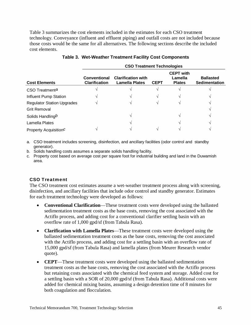
Technical Memorandum 700, Treatment Technology Selection 45
Table 3 summarizes the cost elements included in the estimates for each CSO treatmenttechnology. Conveyance (influent and effluent piping) and outfall costs are not included becausethose costs would be the same for all alternatives. The following sections describe the includedcost elements.
Table 3. Wet-Weather Treatment Facility Cost Components
CSO Treatment Technologies
Cost ElementsConventionalClarification
Clarification withLamella Plates CEPT
CEPT withLamellaPlates
BallastedSedimentation
CSO Treatmenta
Influent Pump StationRegulator Station UpgradesGrit Removal
Solids Handlingb
Lamella Plates
Property Acquisitionc
a. CSO treatment includes screening, disinfection, and ancillary facilities (odor control and standbygenerator).
b. Solids handling costs assumes a separate solids handling facility.c. Property cost based on average cost per square foot for industrial building and land in the Duwamish
area.
CSO TreatmentThe CSO treatment cost estimates assume a wet-weather treatment process along with screening,disinfection, and ancillary facilities that include odor control and standby generator. Estimatesfor each treatment technology were developed as follows:
Conventional Clarification—These treatment costs were developed using the ballastedsedimentation treatment costs as the base costs, removing the cost associated with theActiflo process, and adding cost for a conventional clarifier settling basin with anoverflow rate of 1,000 gpd/sf (from Tabula Rasa).
Clarification with Lamella Plates—These treatment costs were developed using theballasted sedimentation treatment costs as the base costs, removing the cost associatedwith the Actiflo process, and adding cost for a settling basin with an overflow rate of15,000 gpd/sf (from Tabula Rasa) and lamella plates (from Meurer Research vendorquote).
CEPT—These treatment costs were developed using the ballasted sedimentationtreatment costs as the base costs, removing the cost associated with the Actiflo processbut retaining costs associated with the chemical feed system and storage. Added cost fora settling basin with a SOR of 20,000 gpd/sf (from Tabula Rasa). Additional costs wereadded for chemical mixing basins, assuming a design detention time of 8 minutes forboth coagulation and flocculation.

Technical Memorandum 700, Treatment Technology Selection 46
CEPT with Lamella Plates —These treatment costs were developed using the ballastedsedimentation treatment costs as the base costs, removing the cost associated with theActiflo process but retaining costs associated with the chemical feed system and storage.Added costs for a settling basin with lamella plates with a SOR of 20,000 gpd/sf (fromTabula Rasa). Additional costs were added for chemical mixing basins, assuming adesign detention time of 8 minutes for both coagulation and flocculation.
Ballasted Sedimentation—The Omaha tool provided a cost curve for treatmentincluding the following components: 4-mm fine screens, Actiflo system (chemicalinjection tank, flocculation tank, settling tank), sump pumps for dewatering, UVdisinfection, polymer feed system, coagulant feed system, and microsand storage. Theballasted sedimentation cost component is approximately 35 to 55 percent of the wet-weather treatment facility costs.
Influent Pump StationCosts for each treatment technology include an influent pump station to lift flows to thetreatment facility. The Tabula Rasa cost tool for pump stations assumes an excavation depth of30 feet and a total design head of 35 feet.
Regulator Station UpgradesCosts for each treatment technology include upgrades to the existing regulator station to routeflows to and from the treatment facility. The Tabula Rasa cost tool for regulator station was usedassuming an above-grade structure would be required.
Grit RemovalPer manufacturer recommendations, grit removal costs were added only to the ballastedsedimentation facility to protect the equipment from plugging. Costs were obtained fromplanning-level unit costs ($/mgd) obtained from facilities with different types of grit removalsystems, including vortex structures.
Solids Holding BasinSeparate solids handling facility costs were included for facilities where the CSO treatmentsettling basin would not provide sufficient solids storage. Influent (TSS) loads were calculatedusing 32 years of King County overflow data from storm events. Total solids was estimatedusing the influent TSS loads, assuming 85% TSS removal, and 2.5% solids concentration. The85% TSS removal is representative of the average TSS removal performance of the Clarificationwith lamella plates, CEPT with lamella plates, and ballasted sedimentation treatment processes.TSS removal efficiencies of the each treatment process is discussed further in Section 7.2.3. Thetotal solids calculated were compared to the settling basin area calculated assuming the CSOpeak flow rate (not equalized peak flow rate).Conventional clarification and CEPT treatment technologies provide settling basins withsufficient volume to store the solids generated during treatment, due to their lower SORsrequiring larger settling basin areas. Clarification with lamella plates, CEPT with lamella plates,and ballasted sedimentation will require a separate solids holding basin due to the smallersettling basin area available with those technologies’ higher SOR.

Technical Memorandum 700, Treatment Technology Selection 47
Lamella PlatesFor planning level cost estimating, lamella plate costs were obtained from the manufacturerassuming stainless steel lamella plates installed at a 55-degree angle with a ratio of horizontalprojected surface area to clarification surface area of 11.5, similar to the King County CSO pilottests.
Property AcquisitionProperty acquisition costs are included based on footprint curves developed for each treatmenttechnology. Land cost of $114.47 per square foot was used, based on the average land cost ofproperty in the Duwamish area, where CSO treatment facilities are most likely.
Cost SummaryFigure 4 shows construction and property acquisition cost estimates for the five treatmenttechnologies.
$0
$20,000,000
$40,000,000
$60,000,000
$80,000,000
$100,000,000
$120,000,000
$140,000,000
$160,000,000
0 20 40 60 80 100 120 140 160 180
$ m
illio
ns
Flow, mgd
Ballasted Sedimentation
CEPT wth Lamella Plates
CEPT
Conventional Clarification
Clarification with Lamella Plates
Figure 4 Construction Costs Comparison (ENR CCI: 8645.35, Seattle, January 2010)
The results can be summarized as follows:
Conventional clarification has the highest estimated cost, associated with a larger settlingbasin and land acquisition.

Technical Memorandum 700, Treatment Technology Selection 48
CEPT facilities are the second highest in construction cost, due to costs associated with alarger settling basin, chemical mixing basins, and land acquisition.
Ballasted sedimentation and CEPT with lamella plates are similar in total constructioncost, but the costs for ballasted sedimentation are due to equipment costs and those forCEPT with lamella plates are associated with settling basin size, chemical mixing basinsand land acquisition.
Clarification with lamella plates is the least expensive technology due to the lack ofchemical mixing basins and moderate land acquisition requirements.
7.2.2 Operating CostsOperating costs for the CSO treatment facilities were not developed as part of this technicalmemorandum but are evaluated in the Technical Memorandum 620, Cost EstimatingMethodology for CSO Control Facilities. The following operation and maintenance costs areconsidered:
Staffing—Staffing during normal operations will consist of major preventive workbefore and after CSO events. Staffing directly related to storm events will consist ofsampling and monitoring during the events and preparing the facility for the next event.
Power—Ballasted sedimentation, CEPT and CEPT with lamella plates will have higherpower costs associated with sludge pumps and chemical feed systems. Equipmentassociated with conventional clarification and clarification with lamella plates treatmentprocesses do not have power requirements.
Chemicals—Ballasted sedimentation, CEPT and CEPT with lamella plates will havecosts associated with chemical feed of polymer and coagulant. Costs will depend on thefeed rates required to meet performance requirements.
Operating costs for the Lawrence, Kansas Wet-weather Treatment Facility were collected over aperiod of two years. The costs included chemical costs (ferric chloride and polymer), operationslabor (1 FTE during an event), and maintenance labor (0.25 FTE). Total operating cost wasestimated to be $93.21 per million gallons of treated flow.
7.2.3 Unit Costs Based on Treatment Performance
Unit Cost per Pound of TSS RemovedA comparative analysis of the construction cost and TSS removal efficiency of the five CSOtreatment technologies was performed as follows:
Calculate annual average TSS influent load:– Use 32 years of King County overflow volume from storm events in 10 King
County CSO basins where treatment will be considered.
– Assume a TSS concentration of 120 mg/L.
For each technology, calculate a minimum and maximum TSS removal (pounds per year)based on the following TSS removal efficiencies:
– Conventional Primary—50 percent to 70 percent

Technical Memorandum 700, Treatment Technology Selection 49
– Clarification with Lamella Plates—50 percent to 70 percent– CEPT—60 percent to 90 percent
– CEPT with Lamella Plates—60 percent to 90 percent– Ballasted Sedimentation—75 percent to 90 percent.
Divide the construction cost shown on Figure 4 by the range of annual average TSSremoval for each treatment technology.
Figure 5 shows the results, which may be summarized as follows:
Ballasted sedimentation is the most cost-effective because it has the highest TSS removalefficiency and a construction cost comparable to the other treatment technologies.
Conventional clarification has the highest unit cost per pound of annual average TSSremoved, due to its high construction costs and low removal rate.
The unit construction cost per pound of annual average TSS removed is similar for CEPT,CEPT with lamella plates and clarification with lamella plates.
The unit construction cost per pound of annual average TSS removed is highly sensitiveto the range of TSS removal efficiency.
$0
$500
$1,000
$1,500
$2,000
$2,500
$3,000
$ pe
r lb
of A
nnua
l Av
erag
e TS
S re
mov
ed
CSO Alternatives
BALLASTED SEDIMENTATION
CEPT W/ LAMELLAS
CLARIFICATION W/ LAMELLA PLATES
CEPT
CONVENTIONAL CLARIFICATION
Figure 5 Unit Construction Costs per Pound of Annual Average TSS Removed (ENRCCI: 8645.35, Seattle, January 2010)
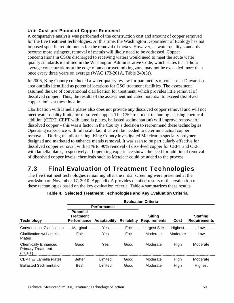
Technical Memorandum 700, Treatment Technology Selection 50
Unit Cost per Pound of Copper RemovedA comparative analysis was performed of the construction cost and amount of copper removedfor the five treatment technologies. At this time, the Washington Department of Ecology has notimposed specific requirements for the removal of metals. However, as water quality standardsbecome more stringent, removal of metals will likely need to be addressed. Copperconcentrations in CSOs discharged to receiving waters would need to meet the acute waterquality standards identified in the Washington Administrative Code, which states that 1-houraverage concentrations at the edge of an approved mixing zone may not be exceeded more thanonce every three years on average (WAC 173-201A, Table 240(3)).
In 2006, King County conducted a water quality review for parameters of concern at Duwamisharea outfalls identified as potential locations for CSO treatment facilities. The assessmentassumed the use of conventional clarification for treatment, which provides little removal ofdissolved copper. Thus, the results of the assessment indicated potential to exceed dissolvedcopper limits at these locations.Clarification with lamella plates also does not provide any dissolved copper removal and will notmeet water quality limits for dissolved copper. The CSO treatment technologies using chemicaladdition (CEPT, CEPT with lamella plates, ballasted sedimentation) will improve removal ofdissolved copper – this was a factor in the County’s decision to recommend these technologies.Operating experience with full-scale facilities will be needed to determine actual copperremovals. During the pilot testing, King County investigated Metclear, a specialty polymerdesigned and marketed to enhance metals removal. It was seen to be particularly effective fordissolved copper removal, with 81% to 90% removal of dissolved copper for CEPT and CEPTwith lamella plates, respectively. If operating experience shows the need for additional removalof dissolved copper levels, chemicals such as Metclear could be added to the process.
7.3 Final Evaluation of Treatment TechnologiesThe five treatment technologies remaining after the initial screening were presented at theworkshop on November 17, 2010. Appendix A provides detailed results of the evaluation ofthese technologies based on the key evaluation criteria. Table 4 summarizes these results.
Table 4. Selected Treatment Technologies and Key Evaluation Criteria
Evaluation CriteriaPerformance
Technology
PotentialTreatment
Performance Adaptability ReliabilitySiting
Requirements CostStaffing
Requirements
Conventional Clarification Marginal Yes Fair Largest Site Highest LowClarification w/ LamellaPlates
Fair Yes Fair Moderate Moderate Low
Chemically EnhancedPrimary Treatment(CEPT)
Good Yes Good Moderate High Moderate
CEPT w/ Lamella Plates Better Limited Good Moderate High ModerateBallasted Sedimentation Best Limited Good Moderate High Highest

Technical Memorandum 700, Treatment Technology Selection 51
Based on the analysis performed at the workshop, the following technologies were removed fromfurther consideration:
Conventional Clarification—Per the recommendation of County management thistechnology was not carried forward. In addition to having the highest cost of the settlingtechnologies (as a result of the size required) and the largest site/land requirements, thepotential treatment performance for conventional clarification is considered to bemarginal for the Duwamish River. Consequently, conventional clarification does notmeet one of the County’s basic goals and objectives, which is to consistently and reliablycomply with all effluent permit limits, water quality standards, and sediment qualitystandards.
Clarification with Lamella Plates—While clarification with lamella plates improves onthe performance of conventional clarification, reducing costs and site requirements, thereare still concerns regarding its ability to consistently and reliably comply with all effluentpermit limits, water quality standards, and sediment quality standards in wet-weatherapplications without some form of chemical addition or without relying on flow capture.Limited King County pilot test runs indicated that TSS removals of 60 percent could beachieved using clarification with lamella plates. Further testing and evaluation would berequired to verify that these results can be consistently and reliably achieved in full-scalewet-weather applications. Therefore, this technology was screened out from the currentevaluation.
CEPT—This technology was screened from further consideration only because CEPTwith lamella plates offers the same benefits with the potential for improved settlingperformance at minimal additional cost.
The following treatment technologies remain for detailed evaluation:
CEPT with lamella plates
Ballasted Sedimentation.Ballasted sedimentation and CEPT with lamella plates are comparable in construction costs andprovide the highest levels of treatment, with TSS removal rates from 50 to 90 percent.
7.4 Final Evaluation of Disinfection TechnologiesA more detailed evaluation of each disinfection technology remaining after the initial screeningwas performed based on the following key evaluation factors, which are summarized inAppendix B:
Disinfection effectiveness
Contact time requirements
Existing installations
Additional potential treatment benefits
Formation of disinfection byproducts
Disinfection residuals
Technical Memorandum 700, Treatment Technology Selection 52
Effluent toxicity
TSS and particle shielding
Chemical addition
Chemical handling and storage requirements
Constructability
Operation and maintenance
Public perception.Based on this secondary evaluation, UV is the recommended disinfection technology if used incombination with one of the two selected treatment technologies (ballasted sedimentation orCEPT with lamella plates), which provide adequate levels of upstream treatment for use with UV.Clarification with lamella plates and CEPT would likely provide adequate levels of treatment foruse with UV, but further evaluation is recommended if these treatment technologies are selected.Only conventional clarification is considered to provide marginal or inadequate levels oftreatment for use with UV.Should a treatment technology be selected that is not fully compatible with UV, then chlorinationwith sodium hypochlorite is the recommended disinfection technology. While peracetic acid,chlorine dioxide, and BCDMH all offer potential advantages relative to sodium hypochlorite,they all also present significant disadvantages, with limited experience treating wet-weatherflows in the United States (primarily based on pilot studies and testing to date). Therefore, thesethree disinfection technologies are not recommended for use by King County in wet-weatherapplications at the current time. However, continued monitoring of these technologies isrecommended as they continue to be developed and implemented in full-scale wet-weatherapplications.


Technical Memorandum 700, Treatment Technology Selection 53
8.0. ASSESSMENT OF SELECTEDTECHNOLOGIES
8.1 Summary DescriptionThe treatment and disinfection technologies selected for the alternatives development phase ofthe 2012 CSO Control Program Review are summarized below.
8.1.1 CEPT with Lamella PlatesCEPT with lamella plates improves on conventional clarification by providing chemical feeds toenhance the coagulation, flocculation, and removal of suspended solids. Inclined plates near thetop of the clarifier increase the sedimentation basin’s effective settling area. This in turn reducesthe footprint requirements and improves performance. Figure 6 is a sample process flowschematic for CEPT with lamella plates.Key advantages and disadvantages of this technology are as follows:
Provides good treatment that reliably met permit requirements during County pilot-testing.
Can provide enhanced removal of copper and other potential parameters of concern.
Moderately complex process that requires additional staffing, primarily due to theadditional chemical storage and feed facilities.
Relatively high capital and O&M costs.
Figure 6 Sample Process Flow Schematic for CEPT with Lamella Plates

Technical Memorandum 700, Treatment Technology Selection 54
8.1.2 Ballasted SedimentationThis technology uses CEPT with lamella plates in combination with a ballast material(microsand or recirculated sludge, depending on the proprietary process selected) to optimizesettling and provide the best potential treatment within the smallest footprint. However, thesefacilities have the highest cost of the assessed technologies and are anticipated to require thegreatest staffing levels. This process is currently in use at numerous U.S. and internationalwastewater treatment plants for wet-weather flow treatment, as well as in several wet-weatherinstallations remote from a treatment plant. Key advantages and disadvantages of this technologyare as follows:
Provides the best treatment performance of all technologies evaluated.
Highest capital and O&M costs of assessed technologies.
More sophisticated process with the highest staffing requirements.Figure 7 is a sample process flow schematic for ballasted sedimentation.
Figure 7 Sample Process Flow Schematic for Ballasted Sedimentation
8.2 Treatment Performance
8.2.1 Removal EfficienciesCEPT with lamella plates can achieve TSS removals between 60 and 90 percent at SORs greaterthan 5,000 gpd/sf. The King County pilot-test report recommended a design SOR of 20,000gpd/sf for CEPT with lamella plates, which can provide TSS removals up to 90 percent based onthe pilot-test results. Ballasted sedimentation can typically achieve TSS removals between 75and 90 percent—similar to CEPT with lamella plates at the upper end of the range and higherthan CEPT with lamella plates at the lower end of the range. This indicates that ballastedsedimentation is generally a more consistent treatment process with more uniform results.

Technical Memorandum 700, Treatment Technology Selection 55
Removal rates for other parameters are as follows for the two selected treatment technologies:
Settleable Solids—Both technologies achieve high levels of settleable solids removal(greater than or equal to 90 percent).
BOD and COD—BOD and COD removal efficiencies can be as high as 70 percent forboth technologies. The minimum expected BOD and COD removal is slightly higher forballasted sedimentation than for CEPT with lamella plates (55 percent versus 40 percent).
Free Oil, Grease, and Floatables—Both selected technologies can provide removal ofthese parameters via scum removal devices.
The King County pilot test measured removal percentages for CEPT with lamella plates for thefollowing parameters (it is expected that ballasted sedimentation can achieve comparableremoval efficiencies):
PCB—90-percent removal based on the recommended design SOR and feed chemicals(PAX).
Nitrogen—Some removal of organic nitrogen was observed (around 10 percent), whichwas attributed to the removal of solids. However, no removal of ammonia or inorganicnitrogen was observed, which is expected.
Phosphorus—Total phosphorus removal greater than 80 percent was reported.
Copper—Using the recommended feed chemical (PAX), up to 49-percent removal oftotal copper was reported (29 percent removal of dissolved copper). This removal wasfurther enhanced with the addition of MetClear, a specialty polymer designed andmarketed to enhance metals removal. Using MetClear in combination with PAXincreased the total copper removal to 80 percent, with 90 percent removal of dissolvedcopper.
Other Metals—Significant removal (>50 percent) of several other metals was reportedwhen using MetClear at various SORs. This included arsenic, cadmium, chromium, iron,lead, mercury, and silver.
Phthalates-Using the recommended feed chemical (PAX), up to 31-percent removal ofBis(2-Ethylhexyl)Phthalate was reported for CEPT. The addition of Metclear incombination with PAX further enhanced removals, increasing the percent removal to 85-percent for CEPT with lamella plates.
Polycyclic Aromatic Hydrocarbons (PAHs)-Up to 37-percent removal was reported forPhenanthrene, a PAH, when using PAX alone. While the pilot study did not test forremoval efficiencies using PAX with Metclear, the results for Bis(2-Ethylhexyl)Phthalateindicate the potential to further enhance removal efficiencies for Phenanthrene and otherPAHs by using PAX in combination with Metclear or other specialty polymers.
Based on these removal efficiencies, both technologies are compatible with the use of UVdisinfection. If used with chemical disinfection technologies, these enhanced removalefficiencies are also expected to positively benefit disinfection performance.

Technical Memorandum 700, Treatment Technology Selection 56
8.2.2 Surface Overflow RatesThe most significant difference between ballasted sedimentation and CEPT with lamella plates isthe design SORs: 57,600 to 86,400 gpd/sf for the DensaDeg process and 72,000 to 115,200gpd/sf for the Actiflo process compared to 20,000 gpd/sf for CEPT with lamella plates. Ballastedsedimentation will generally achieve solids removal efficiencies up to 90 percent at design SORsthat are 3 to 5 times greater than those for CEPT with lamella plates, with more uniform andconsistent performance.
8.3 Hydraulic PerformanceBoth selected treatment technologies have comparable hydraulic profiles. Based on the hydraulicprofile for the ballasted sedimentation process at Bremerton, Washington, where the head loss atthe peak design flow is 3.3 feet, the expected hydraulic profile for both selected technologies isexpected to be in the range of 3 to 4 feet, depending on the specific hydraulic design of eachfacility.
8.4 Sediment Recontamination RisksThe potential for the CSO effluent to deposit sediment and create an area in exceedence ofWashington State’s sediment quality standards (SQS) was evaluated using a 3-Dimensionalhydrodynamic transport model (Environmental Fluid Dynamics Code, EFDC). CSO dischargelocations within the Lower Duwamish Waterway, East Waterway, and Elliott Bay were modeledwith discharge hydrographs developed from hydrological modeling. Chemical concentrationswere assigned to particles in the CSO effluent based on the mean concentration of previous CSOcharacterization sampling. The sediment modeling results can be found in the TechnicalMemorandum 750, Sediment Deposition and Contamination Potential from Treated CSODischarges.Ambient sedimentation rates were taken from conceptual site models and sedimentation ratesmeasured in cores collected in the Lower Duwamish Waterway, East Waterway and Elliott Bay.Ambient sedimentation concentrations were taken from existing surface sediment samples.
Both selected treatment technologies have relatively high levels of TSS removal, reducing theloading rate of solids relative to the existing CSO discharges. The expected loading rates fromboth of the selected treatment alternatives are sufficiently low that no sediment qualityexceedences were predicted in any of the conditions modeled.
8.5 Greenhouse Gas EmissionsInfrastructure projects require a Washington State Environmental Policy Act (SEPA) checklist(WAC 197-11-960) that identifies, among other potential project impacts, the likely sources ofgreenhouse gas emissions. The checklist must identify air emissions expected duringconstruction and when the project is completed.
King County has developed a worksheet for estimating greenhouse gas emissions for most typesof buildings, including CSO treatment facilities. The worksheet was used to estimate greenhousegas emissions for the ballasted sedimentation CSO treatment process. The methodology is asfollows:

Technical Memorandum 700, Treatment Technology Selection 57
Estimate footprint of proposed CSO treatment facility, including equalization basin,influent pump station, CSO treatment process (ballasted sedimentation) and disinfection(UV).
Using footprint calculations, estimate total excavation quantities and constructionmaterial quantities (concrete, aggregate, steel).
Using footprint calculations, estimate square footage of conditioned spaces for energyusage.
Calculate total emissions in metric tons of carbon dioxide (MT CO2) over the lifespan ofthe facility (assumed to be 62.5 years) for each of the following:– Embodied Emissions—Emissions created through transportation, construction
and disposal of building materials and soil excavation during construction.– Energy Emissions— Emissions related to energy consumption (electricity and
natural gas), based on energy consumption at existing King County CSOtreatment facilities (Mercer/Elliott West and Alki CSO Treatment Plant) andestimated footprint of CSO treatment facility.
– Transportation Emissions—Emissions related to transportation of staffing to theCSO treatment facilities, based on existing King County CSO treatment facilitiesO&M estimates where staff requirements range from 1.8 to 2.7 full timeequivalents (FTE), assuming staffing of 2 FTE per 5,000 square feet of facilityfootprint.
The greenhouse gas emissions were estimated for three treatment and equalization designcapacities for the CSO treatment facilities assuming a ballasted sedimentation CSO treatmentprocess. Table 5 summarizes that estimated gas emissions. The spreadsheets used to develop theestimates are provided in Appendix C.
Table 5 Greenhouse Gas Emissions Estimates
Estimated Greenhouse Gas Emissions (MT CO2)Equalization: 0.89 MG,
Treatment: 66 mgdEqualization: 0.97 MG,
Treatment: 94 mgdEqualization: 1.71 MG,
Treatment:151 mgdTotal Emissions 14,990 20,235 30,770


Technical Memorandum 700, Treatment Technology Selection 58
9.0. REFERENCES
Arnett, Clifford J.; Boner, Mark; Bowman, Jessica. 2007. Management of Pathogens andIndicator Organisms in Urban Area Watersheds: Optimizing Wet-Weather Disinfection withAdaptive Technologies. Proceedings of the Water Environment Federation, Disinfection 2007,pp. 166-174(9). Water Environment Federation
Bodimeade, Carl; Corbett, Rick; Hribljan, Michael; Chauvin, Dan. 2005. A Tale of TwoProcesses – Piloting of High Rate Treatment Processes at Woodward Avenue WastewaterTreatment Plant. Proceedings of the Water Environment Federation, Collection Systems 2005,pp. 239-254(16). Water Environment Federation.
Constantine, Tim A.; Brook, Dave; Crawford, George; Sacluti, Fernando; Black, Steve;McKenna, Dave. 2003. The Disinfection Potential of Two Enhanced Primary TreatmentTechnologies Treating Wet Weather Flow at Edmonton, Gold Bar WWTP. Proceedings of theWater Environment Federation, WEFTEC 2003: Session 21 through Session 30, pp. 211-224(14)Water Environment Federation.
Electric Power Research Institute, Inc. 1999. High Rate Clarification for the Treatment of WetWeather Flows. EPRI Municipal Water and Wastewater Program, Washington University, CB1150, Cupples II Room 11, One Brookings Drive, St. Louis, MO 63130-4899. Fromhttp://listserver.energy.ca.gov/process/pubs/highrt_clarificatn_tc113574.pdf.
Frank, David A.; Smith, Thomas F. 2006. Side by Side by Side the Evaluation of Three HighRate Process Technologies for Wet Weather Treatment. Proceedings of the Water EnvironmentFederation, WEFTEC 2006: Session 81 through Session 94, pp. 6723-6747(25). WaterEnvironment Federation
Keller, John; Kobylinski, A.; Hunter, Gary L.; Fitzpatrick, James D. 2005. Actiflo: A Year’sWorth of Operating Experience from the Largest SSO System in the US. Proceedings of theWater Environment Federation, WEFTEC 2005: Session 1 through Session 10 , pp. 396-420(25).Water Environment Federation.
Keogh, Brian and Tran, Minh. 2011. Old City, New Ideas: Peracetic Acid in WastewaterDisinfection at St. Augustine. Florida Water Resources Journal, April 2011, pp. 44-48.
King County Department of Natural Resources and Parks, Wastewater Treatment Division. 1999.Task 300 Technical Memorandum, Year 2000 CSO Plan Update Project, AlternativeTechnologies for CSO Control. Seattle, WA.King County Department of Natural Resources and Parks, Wastewater Treatment Division. 2006.Combined Sewer Overflow Control Program. CSO Control Program Review. Seattle, WA.King County Department of Natural Resources and Parks, Wastewater Treatment Division. 2007.Task 500 Technical Memorandum, Combined Sewer Overflow Control Program. 2008 CSOControl Program Update. Seattle, WA.
King County Department of Natural Resources and Parks, Wastewater Treatment Division. 2008.Combined Sewer Overflow Control Program. 2008 CSO Control Program Update. Seattle, WA.

Technical Memorandum 700, Treatment Technology Selection 59
King County Department of Natural Resources and Parks, Wastewater Treatment Division. 2009.Test Plan for Combined Sewer Overflow Treatment Systems Evaluation and Testing – Phase 2.Contract No. E00046E06. Seattle, WA.King County Department of Natural Resources and Parks, Wastewater Treatment Division. 2010.CSO Pilot Study (Final) Contract No. E00046E06. Combined Sewer Overflow TreatmentSystems Evaluation and Testing, Phase 2, Subtask 340 – Pilot Test Report. Seattle, WA.
Kurtz, Warren; Muller, James G.; Laurence, Antoine; Smith, Robert D.; Young, Peter J. 2003.Pilot Testing of High Rate Physical-Chemical Treatment for Wet Weather Treatment.Proceedings of the Water Environment Federation, WEFTEC 2003: Session 41 through Session50 , pp. 452-464(13). Water Environment Federation
Landon, Susan K.; Cruden, Donald; Donahue, Colleen; Jeyanayagam, Sam. 2005. High RateClarification Treatment for Wet Weather Flows: A side-by-side comparison. Proceedings of theWater Environment Federation, WEFTEC 2005. Session 1 through Session 10 , pp. 363-382(20).Water Environment Federation
McKern, Russ; Days, Paula; Matthews, Sharon; White, Christopher; Andoh, Robert; Boner,Mark. 2004. Atlanta CSO Pilot Plant Performance Results. Proceedings of the WaterEnvironment Federation, WEFTEC 2004. Session 31 through Session 40, pp. 537-555(19).Water Environment Federation
Melcer, Henryk; Krugel, Steve; Butler, Rick; Carter, Pete. 2005. Alternative OperationalStrategies to Control Pollutants in Peak Wet Weather Flows. Proceedings of the WaterEnvironment Federation, WEFTEC 2005: Session 101 through Session 110 , pp. 8514-8535(22).Water Environment Federation (note: King County paper)
Moffa, Peter E.; Davis, Daniel P.; Somerlot, Chris; Sharek, Dan; Gresser, Brian; Smith, Tom.2006. Alternative Disinfection Technology Demonstrates Advantages for Wet WeatherApplications—A Pilot Study of Powdered Bromine Technology. Proceedings of the WaterEnvironment Federation, WEFTEC 2006: Session 11 through Session 20, pp. 1202-1218(17).Water Environment FederationMoffa, Peter; LaGorga, John; Henry, Linda; Boner, Mark; Goodrum, Philip; Doherty, Francis;Alexander, Thomas. 2005. Identifying Technologies and Communicating the Benefits and Risksof Disinfecting Wet Weather Flows. 00-HHE-6. Water Environment Research Federation.
Neupane, Dilli R.; Riffat, Rumana; Murthy, Sudhir N.; Peric, Marija R. 2006. Influence ofSource Characteristics, Chemicals and Flocculation on Non-Settleable Solids and ChemicallyEnhanced Primary Treatment. Proceedings of the Water Environment Federation, WEFTEC2006: Session 21 through Session 30 , pp. 1936-1951(16). Water Environment Federation
Nitz, David; Lyon, Tom; Fitzpatrick, James. 2004. Wet Weather Treatment Pilot Testing: HighRate Clarification and UV Disinfection in a Cold Climate Proceedings of the Water EnvironmentFederation, WEFTEC 2004: Session 21 through Session 30, pp. 140-166(27). WaterEnvironment Federation
Ponist, Jeffrey B.; Scheiter, David. 2006. Ballasted High Rate Clarification Process RemovesCity of Greenfield, Indiana as a CSO Community. Proceedings of the Water EnvironmentFederation, Collection Systems 2006, pp. 278-290(13). Water Environment Federation
Technical Memorandum 700, Treatment Technology Selection 60
Schraa, Oliver; Newbigging, Mike; Averill, David; Tanner, Mary Lou; Solomon, Mark; Joyner,Ann. 2010. Evaluation of Wet Weather Treatment Alternatives at the Port Dalhouse WWTP.Proceedings of the Water Environment Association of Ontario Technical Conference 2010.London, Ontario.
Siczka, John; Sandino, Julian; Onderko, Richard; Sigmund, Thomas. 2007. Biologically andChemically Enhanced Clarification for Improved Treatment of Wet-Weather Flows. Proceedingsof the Water Environment Federation, WEFTEC 2007: Session 41 through Session 50 , pp.3441-3451(11). Water Environment Federation
Sigmund, Thomas; Siczka, John; Elliott, Todd; Awad, Jamal; Onderko, Richard. 2006. OperatingChemically Enhanced Clarification for Optimum Disinfection Performance. Proceedings of theWater Environment Federation, WEFTEC 2006: Session 81 through Session 94, pp. 6707-6722(16). Water Environment Federation
Steidel, Robert C.; Stone, Robert; Watson, Clair L.; Maisch, Federico E.; Cronin, Edward J.;Liang, Lin; Guhse, George L. 2005. A Glowing City: Richmond, Virginia Studies Disinfectionof a 5000 mgd CSO Outfall. Proceedings of the Water Environment Federation, WEFTEC 2005:Session 11 through Session 20 , pp. 1468-1499(32). Water Environment Federation
Stevenson, R.; Nitz, David; Middlebrough, Chris; Dyson, John. 2008. Operation of the LargestHigh Rate Clarification System for CSO Control in North America. Proceedings of the WaterEnvironment Federation, WEFTEC 2008. Session 1 through Session 10 , pp. 386-396(11). WaterEnvironment Federation
United States Environmental Protection Agency. 1999. Combined Sewer Overflow TechnologyFact Sheet – Alternative Disinfection Methods. EPA 832-F-99-033. Office of Water, Washington,D.C.Wahlberg, Eric. 2006. Determine the Effect of Individual Wastewater Characteristics andVariances on Primary Clarifier Performance. 00-CTS-2. Water Environment ResearchFederation
Water Environment Federation; American Society of Civil Engineers; Environmental and WaterResources Institute. 2009. Design of Municipal Wastewater Treatment Plants, 5th ed.; WEFManual of Practice No. 8, ASCE Manual of Practice and Report on Engineering No. 76;McGraw-Hill: New York
Wojtenko, Izabela and Stinson, Mary K. 2003. CSO Disinfection Pilot Study: Spring Creek CSOStorage Facility Upgrade. U.S. Environmental Protection Agency. EPA/600/R-02/077. NationalRisk Management Research Laboratory, Office of Research and Development, U.S. EPA,Cincinnati, Ohio


Appendix A
Evaluation Factors for Treatment Technologies


Key Evaluation Factors Conventional Clarification Clarification w/ Lamella Plates Chemically Enhanced Primary Treatment (CEPT) Ballasted Sedimentation
Without Lamella Plates With Lamella Plates
1. Treatment Effectiveness – Removal Efficiencies for the followingconstituents / parameters:
a. Total Suspended Solids (TSS)b. Settleable Solidsc. Biochemical Oxygen Demand (BOD)d. Chemical Oxygen Demand (COD)e. Floatablesf. Future Parameters of Concern (Copper)
TSS Removal = 50-70%Settleable Solids Removal =80-95%BOD or COD Removal = 25-40%Provides removal of free oil,grease, and other floatables viascum removal devices.Negligible Removal ofSoluble Copper; Removal ofParticulate or PrecipitatedCopper Compounds Will BeComparable to TSS Removal.
Performance is comparable toconventional clarification but athigher SORs.
TSS Removal = 60-90%Settleable Solids Removal > 95%BOD or COD Removal = 40-70%Provides removal of free oil, grease, and other floatables viascum removal devices.Can also result in the chemical precipitation and removal ofcolloidal material.Potential for removal of copper and other heavy metals,including the coagulation and precipitation of solubleforms/compounds. Removal of soluble copper/metals will bedependent on the specific chemicals used.
TSS Removal = 75-90%Settleable Solids Removal > 95%BOD or COD Removal = 55-70%Provides removal of free oil,grease, and other floatables viascum removal devices.Potential for removal of copperand other heavy metals, includingthe coagulation and precipitationof soluble forms/compounds.Removal of solublecopper/metals will be dependenton the specific chemicals used.
2. Upstream Treatment Requirementsa. Equalizationb. Screeningc. Grit Removal
Equalization is recommendedto control peak hydraulicloading and optimizeperformance.Screening is recommended toremove the larger rags, debris,and floatables, which willimprove the overallperformance and reduceO&M.Grit removal is optional, asmost of the grit will beremoved along with the TSSand Settleable Solids.
Equalization is recommended tocontrol peak hydraulic loadingand optimize performance.Fine screening and grit removalare recommended to reduce thepotential for fouling or pluggingof the lamella plates with rags,debris, grease, and solids.Otherwise, O&M requirementswill be greater and/orperformance will decrease.
Equalization isrecommended to controlpeak hydraulic loading andoptimize performance.Screening comparable toconventional clarification.Grit removal isrecommended to optimizeperformance and reduceO&M, particularly iflamella plates are included.
Equalization isrecommended to controlpeak hydraulic loading andoptimize performance.Fine screening isrecommended.Grit removal isrecommended to optimizeperformance and reduceO&M, particularly iflamella plates are included.
Equalization is recommended tostabilize hydraulic loading andoptimize performance.Coarse or fine screening(dependent on manufacturerecommendation) and gritremoval are required to preparethe wastewater for the treatmentprocess and optimizeperformance.
3. Existing Installationsa. CSO or Wastewater Treatment Plant (WWTP) Facilities –
United Statesb. CSO or WWTP Facilities – Internationalc. Other Applications or Industries
Widely used at CSO andWWTP facilities throughoutthe world.
Comparable to plate-and-tubesettlers that are widely used inEurope.Limited use at municipal facilitiesin the United States.Commonly used at industrialwastewater facilities.
Several large scale WWTPs in the United States and Canadahave used CEPT.No specific installations for CSO applications.Commonly used at industrial wastewater treatment facilities.
Used at multiple WWTPs forwet-weather flow treatment.Two known locations for CSO orwet-weather treatment remotefrom WWTPs.Additional installations atindustrial sites and drinkingwater facilities.
4. Design Parametersa. Solids / Mass Loadingb. Hydraulic Loadingc. Hydraulic Losses / Head Requirements
Typically not designed basedon solids or mass loading.Hydraulic loading based onSurface Overflow Rate (SOR)= 1,000 gpd/sf.Minimal hydraulic losses;typically less than 2 feet ofhead required.
By increasing the effectivesurface area by a factor of 6 to 12times, the SOR can be increasedby a comparable amount relativeto conventional clarification.Hydraulic losses and headrequirements are comparable toconventional clarification.
SOR up to 5,000 gpd/sf canbe used.Hydraulic losses and headrequirements arecomparable to conventionalclarification.
Lamella plates can be usedto further increase SOR byincreasing the effectivesurface area.Hydraulic losses and headrequirements arecomparable to conventionalclarification.
SOR for settling area = 57,600 to86,400 gpd/sf for DensaDeg;72,000 to 115,200 gpd/sf forACTIFLO.For best performance, hydraulicloading rates should remainstable. Multiple parallel treatmentcomponents should beconsidered.Hydraulic losses and total headrequirements are in the range of 3to 4 feet, which are slightlygreater than conventionalclarification. .
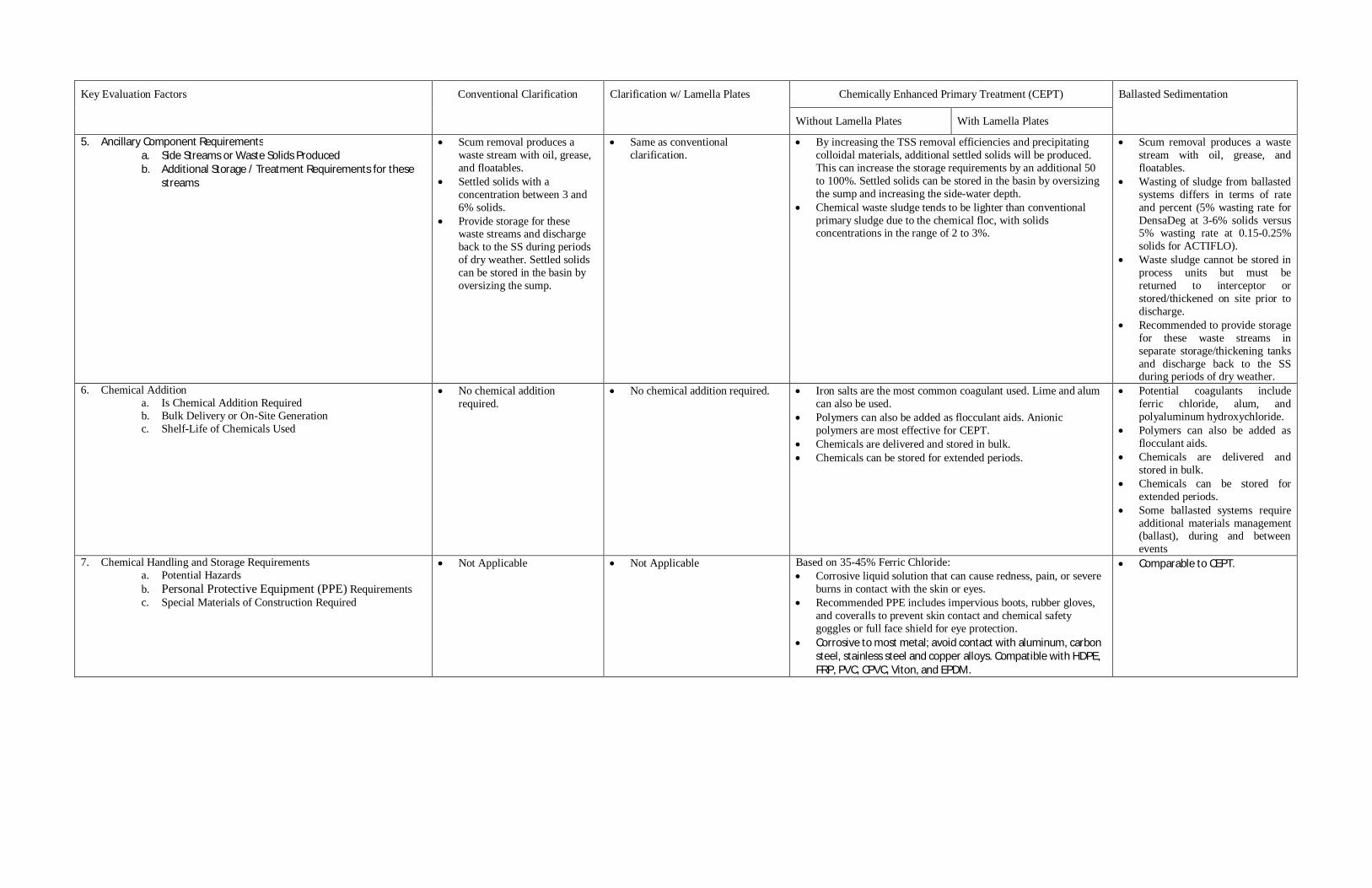
Key Evaluation Factors Conventional Clarification Clarification w/ Lamella Plates Chemically Enhanced Primary Treatment (CEPT) Ballasted Sedimentation
Without Lamella Plates With Lamella Plates
5. Ancillary Component Requirementsa. Side Streams or Waste Solids Producedb. Additional Storage / Treatment Requirements for these
streams
Scum removal produces awaste stream with oil, grease,and floatables.Settled solids with aconcentration between 3 and6% solids.Provide storage for thesewaste streams and dischargeback to the SS during periodsof dry weather. Settled solidscan be stored in the basin byoversizing the sump.
Same as conventionalclarification.
By increasing the TSS removal efficiencies and precipitatingcolloidal materials, additional settled solids will be produced.This can increase the storage requirements by an additional 50to 100%. Settled solids can be stored in the basin by oversizingthe sump and increasing the side-water depth.Chemical waste sludge tends to be lighter than conventionalprimary sludge due to the chemical floc, with solidsconcentrations in the range of 2 to 3%.
Scum removal produces a wastestream with oil, grease, andfloatables.Wasting of sludge from ballastedsystems differs in terms of rateand percent (5% wasting rate forDensaDeg at 3-6% solids versus5% wasting rate at 0.15-0.25%solids for ACTIFLO).Waste sludge cannot be stored inprocess units but must bereturned to interceptor orstored/thickened on site prior todischarge.Recommended to provide storagefor these waste streams inseparate storage/thickening tanksand discharge back to the SSduring periods of dry weather.
6. Chemical Additiona. Is Chemical Addition Requiredb. Bulk Delivery or On-Site Generationc. Shelf-Life of Chemicals Used
No chemical additionrequired.
No chemical addition required. Iron salts are the most common coagulant used. Lime and alumcan also be used.Polymers can also be added as flocculant aids. Anionicpolymers are most effective for CEPT.Chemicals are delivered and stored in bulk.Chemicals can be stored for extended periods.
Potential coagulants includeferric chloride, alum, andpolyaluminum hydroxychloride.Polymers can also be added asflocculant aids.Chemicals are delivered andstored in bulk.Chemicals can be stored forextended periods.Some ballasted systems requireadditional materials management(ballast), during and betweenevents
7. Chemical Handling and Storage Requirementsa. Potential Hazardsb. Personal Protective Equipment (PPE) Requirementsc. Special Materials of Construction Required
Not Applicable Not Applicable Based on 35-45% Ferric Chloride:Corrosive liquid solution that can cause redness, pain, or severeburns in contact with the skin or eyes.Recommended PPE includes impervious boots, rubber gloves,and coveralls to prevent skin contact and chemical safetygoggles or full face shield for eye protection.Corrosive to most metal; avoid contact with aluminum, carbonsteel, stainless steel and copper alloys. Compatible with HDPE,FRP, PVC, CPVC, Viton, and EPDM.
Comparable to CEPT.

Key Evaluation Factors Conventional Clarification Clarification w/ Lamella Plates Chemically Enhanced Primary Treatment (CEPT) Ballasted Sedimentation
Without Lamella Plates With Lamella Plates
8. Compatibility with Downstream Disinfection Technologiesa. Sodium Hypochlorite (NaOCl)b. Ultra Violet (UV)c. Peracetic Acid (PAA)d. Chlorine Dioxide (ClO2)e. BCDMH (Bromine)
Compatible with chemicaldisinfection technologies(NaOCl, PAA, ClO2, andBCDMH).Less compatible with UV,which works best with moreadvanced levels of treatment.
Same as conventionalclarification.
Compatible with chemical disinfection technologies (NaOCl,PAA, ClO2, and BCDMH).Higher levels of treatment provided makes CEPT morecompatible with UV.Use of ferric for coagulation may impact use of UV. Alternativecoagulant should be considered if UV preferred disinfectionapproach.
Sufficiently treats flows for useof preferred disinfectant;compatible with either chemicalor UV disinfection.Use of ferric chloride forcoagulation may impact use ofUV. Alternative coagulant shouldbe considered if UV preferreddisinfection approach
9. Adaptability and Flexibilitya. Performance over wide range of operating conditionsb. Ability to Upgrade in the Future in Response to Changing
Permit Conditions / Requirements
Performance and removalefficiencies decrease at higherflows and hydraulic loadings.Performance decreases withcolder wastewatertemperatures below 68 degreeF.Can be upgraded by addinglamella plates or chemicaladdition in the future.Provisions for future chemicaladdition would include spacefor a futuremixing/coagulation chamberand chemical storage/feedsystems.
The greater effective surface areacan be used to improveperformance at peak flows andloadings while minimizing thehydraulic residence time,reducing the odor potential.Can be upgraded by addingchemical addition in the future.Provisions for future chemicaladdition would include space fora future mixing/coagulationchamber and chemicalstorage/feed systems.
Chemical feed capability provides greater flexibility andimproved performance over a wide range of operatingconditions.Additional chemical feeds, including polymers and othercoagulant aids, can be used to upgrade performance to meetparticular treatment requirements in the future.
Chemical feed capabilityprovides greater flexibility andimproved performance over awide range of operatingconditions.Additional chemical feeds,including polymers and othercoagulant aids, can be used toupgrade performance to meetparticular treatment requirementsin the future.
10. Constructabilitya. Footprint / Area Requirementsb. Single or Multiple Manufacturers/Suppliers
Largest footprint / arearequirements.Multiple manufacturers andsuppliers
Footprint requirements can bereduced by a factor of 6 to 12compared to conventionalclarification.Fewer manufacturers andsuppliers than conventionalclarification.
Smaller footprint / arearequirements thanconventional clarification.Multiple manufacturers ofchemical storage and feedsystems.
Footprint / arearequirements can be furtherreduced by adding lamellaplates.
Smallest footprint / arearequirements.Two primary manufacturers inthe market today:
o ACTIFLOo DensaDeg

Key Evaluation Factors Conventional Clarification Clarification w/ Lamella Plates Chemically Enhanced Primary Treatment (CEPT) Ballasted Sedimentation
Without Lamella Plates With Lamella Plates
11. Operation and Maintenance (O&M)a. Reliability – Performanceb. Reliability—Equipmentc. Ease of Operation / Complexityd. Operator Attendance Requirementse. Preventive Maintenance Requirementsf. Equipment Maintenance Requirementsg. Odor Potentialh. Noise Potentiali. Non-Chemical Consumable Materials Used
Performance is variable and isa function of the influentwastewater characteristics,flows, and temperature.Equipment is very reliable.Very simple to operate.Minimal operator attendancerequired.Minimal preventivemaintenance is required,primarily periodic checks ofthe clarifier mechanism drivegear and lubrication.Minimal equipmentmaintenance required.Odor potential.Very low noise potential.No consumable materialsused.
Comparable to conventionalclarification with the exception ofthe following:
o Reduced odor potential.o Additional maintenance
required for additionalpretreatment (finescreens and gritremoval) or additionalcleaning of the lamellaplates.
Performance is more reliable and can be better controlled thanconventional clarification.Additional complexity of the chemical feed systems reduces theoverall equipment reliability.Operator attendance is required to monitor and control thechemical feed systems.Additional preventive and equipment maintenance is requiredfor the chemical storage tanks and feed systems.Reduced odor potential.Greater noise potential associated with chemical deliveries.
Best performance of identifiedtechnologies.Most complex of various systemsidentified. Chemical feed andballast systems result in thehighest number of systems to bemaintained.Operator attendance is requiredto monitor and control thechemical feed and ballastsystems.Additional preventive andequipment maintenance isrequired for the chemical storagetanks and feed systems. Ballastsystems involve pumps, valvesand other equipment.Reduced odor potential.Greater noise potential associatedwith chemical deliveries;additional equipment.For ACTIFLO system, sandballast must be stocked andreplenished. Maintenance orcleaning of sand ballast betweenevents necessary to prevent “setup.”
12. Public Perception Potential negatives includelarge footprint / arearequirements and more risk ofodor.
Facilities are more amenableto being located below gradewith minimal surface buildingand alternative surface use(e.g. park space)
Expected to be more positive thanconventional clarification due toreduced footprint / arearequirements and reduced odorpotential.
Would likely involve more abovegrade facilities
Delivery and storage of chemicals may negatively impact publicperception.
Reduced footprint / area requirements and reduced odorpotential are expected to enhance public perception.
Would likely involve more above grade facilities
Delivery and storage ofchemicals may negatively impactpublic perception.
Reduced footprint / arearequirements and reduced odorpotential are expected to enhancepublic perception.
Would likely involve more abovegrade facilities

Appendix B
Evaluation Factors for Disinfection Technologies

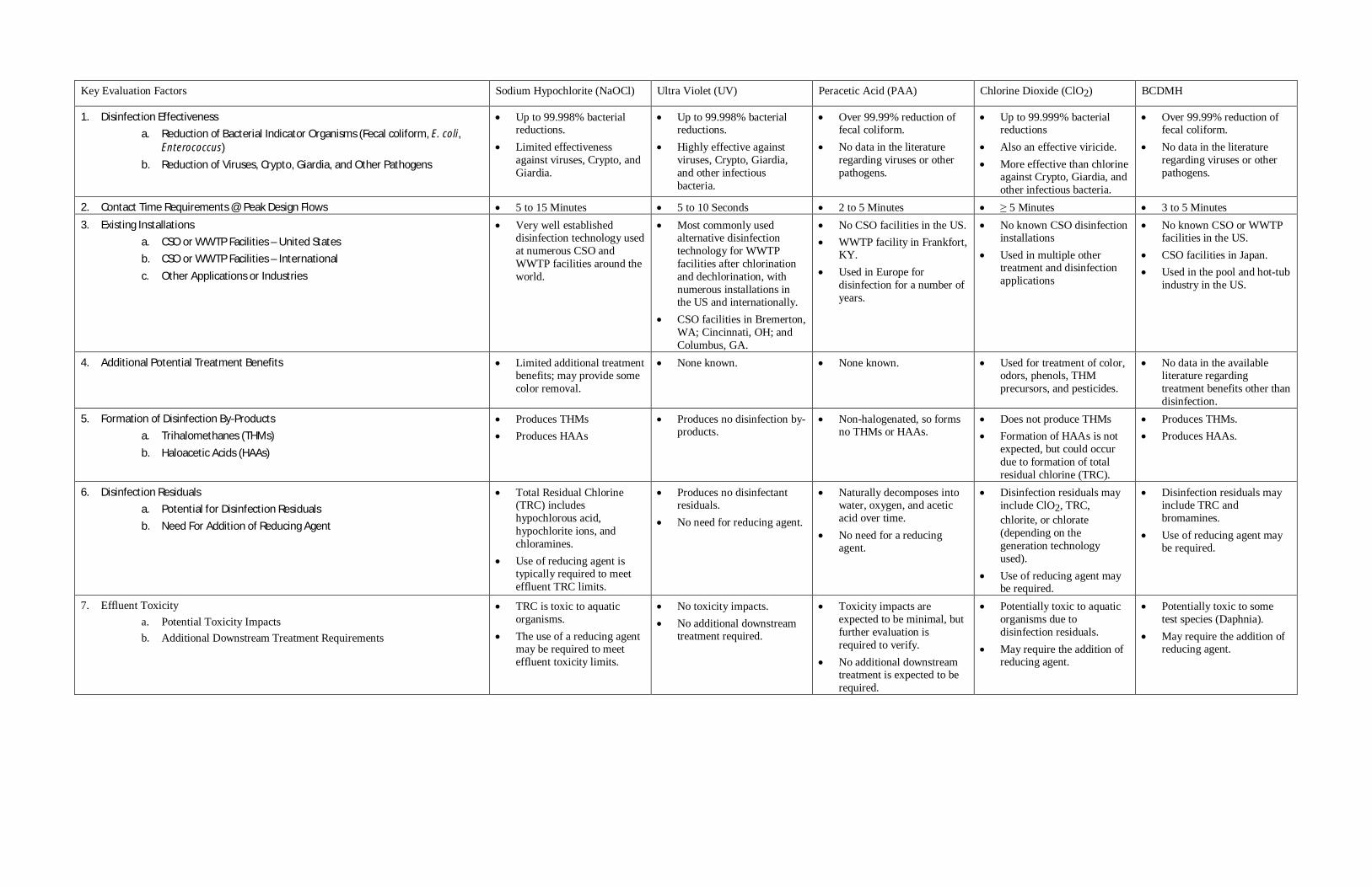
Key Evaluation Factors Sodium Hypochlorite (NaOCl) Ultra Violet (UV) Peracetic Acid (PAA) Chlorine Dioxide (ClO2) BCDMH
1. Disinfection Effectivenessa. Reduction of Bacterial Indicator Organisms (Fecal coliform, E. coli,
Enterococcus)b. Reduction of Viruses, Crypto, Giardia, and Other Pathogens
Up to 99.998% bacterialreductions.Limited effectivenessagainst viruses, Crypto, andGiardia.
Up to 99.998% bacterialreductions.Highly effective againstviruses, Crypto, Giardia,and other infectiousbacteria.
Over 99.99% reduction offecal coliform.No data in the literatureregarding viruses or otherpathogens.
Up to 99.999% bacterialreductionsAlso an effective viricide.More effective than chlorineagainst Crypto, Giardia, andother infectious bacteria.
Over 99.99% reduction offecal coliform.No data in the literatureregarding viruses or otherpathogens.
2. Contact Time Requirements @ Peak Design Flows 5 to 15 Minutes 5 to 10 Seconds 2 to 5 Minutes 5 Minutes 3 to 5 Minutes3. Existing Installations
a. CSO or WWTP Facilities – United Statesb. CSO or WWTP Facilities – Internationalc. Other Applications or Industries
Very well establisheddisinfection technology usedat numerous CSO andWWTP facilities around theworld.
Most commonly usedalternative disinfectiontechnology for WWTPfacilities after chlorinationand dechlorination, withnumerous installations inthe US and internationally.CSO facilities in Bremerton,WA; Cincinnati, OH; andColumbus, GA.
No CSO facilities in the US.WWTP facility in Frankfort,KY.Used in Europe fordisinfection for a number ofyears.
No known CSO disinfectioninstallationsUsed in multiple othertreatment and disinfectionapplications
No known CSO or WWTPfacilities in the US.CSO facilities in Japan.Used in the pool and hot-tubindustry in the US.
4. Additional Potential Treatment Benefits Limited additional treatmentbenefits; may provide somecolor removal.
None known. None known. Used for treatment of color,odors, phenols, THMprecursors, and pesticides.
No data in the availableliterature regardingtreatment benefits other thandisinfection.
5. Formation of Disinfection By-Productsa. Trihalomethanes (THMs)b. Haloacetic Acids (HAAs)
Produces THMsProduces HAAs
Produces no disinfection by-products.
Non-halogenated, so formsno THMs or HAAs.
Does not produce THMsFormation of HAAs is notexpected, but could occurdue to formation of totalresidual chlorine (TRC).
Produces THMs.Produces HAAs.
6. Disinfection Residualsa. Potential for Disinfection Residualsb. Need For Addition of Reducing Agent
Total Residual Chlorine(TRC) includeshypochlorous acid,hypochlorite ions, andchloramines.Use of reducing agent istypically required to meeteffluent TRC limits.
Produces no disinfectantresiduals.No need for reducing agent.
Naturally decomposes intowater, oxygen, and aceticacid over time.No need for a reducingagent.
Disinfection residuals mayinclude ClO2, TRC,chlorite, or chlorate(depending on thegeneration technologyused).Use of reducing agent maybe required.
Disinfection residuals mayinclude TRC andbromamines.Use of reducing agent maybe required.
7. Effluent Toxicitya. Potential Toxicity Impactsb. Additional Downstream Treatment Requirements
TRC is toxic to aquaticorganisms.The use of a reducing agentmay be required to meeteffluent toxicity limits.
No toxicity impacts.No additional downstreamtreatment required.
Toxicity impacts areexpected to be minimal, butfurther evaluation isrequired to verify.No additional downstreamtreatment is expected to berequired.
Potentially toxic to aquaticorganisms due todisinfection residuals.May require the addition ofreducing agent.
Potentially toxic to sometest species (Daphnia).May require the addition ofreducing agent.

Key Evaluation Factors Sodium Hypochlorite (NaOCl) Ultra Violet (UV) Peracetic Acid (PAA) Chlorine Dioxide (ClO2) BCDMH
8. TSS / Particle Shieldinga. Impact on Disinfection Effectivenessb. Upstream Treatment Requirements
Limited ImpactMinimal upstream treatmentrequired (screening and gritremoval)Additional treatmentimproves performance.
Particle shielding byparticulates / TSS willnegatively impactperformance.Performance is also directlyrelated to UV transmittance(UVT).Higher levels of upstreamtreatment are thereforerecommended for TSSremoval, turbidity removal,and maximum UVT.
Limited ImpactMinimal upstream treatmentrequired (screening and gritremoval)Additional treatmentimproves performance.
Limited ImpactMinimal upstream treatmentrequired (screening and gritremoval)Additional treatmentimproves performance.
Limited ImpactMinimal upstream treatmentrequired (screening and gritremoval).Additional treatmentimproves performance.
9. Chemical Additiona. Is Chemical Addition Requiredb. Bulk Delivery or On-Site Generationc. Shelf-Life of Chemicals Used
Chemical AdditionRequired.Bulk Delivery.Limited shelf-life thatbegins to lose strength after30 days for a 12.5%solution.
No chemical additionrequired.No chemical deliveries.No chemical shelf-lifeissues.
Chemical AdditionRequired.Bulk Delivery.Includes a stabilizer toincrease shelf-life to over 12months.
Chemical AdditionRequired.On-site generation.Feed stock chemicals can bestored for up to 6 months.
Chemical AdditionRequired.On-site generation of feedsolution using dry powder.Powder can be stored aslong as a year.
10. Chemical Handling and Storage Requirementsa. Potential Hazardsb. PPE Requirementsc. Special Materials of Construction Required
Nonflammable andnoncombustible liquid witha pH of 11.2 to 11.4 thatwill react with ammoniacompounds. Eye and skinirritant; vapors may causeirritation to upperrespiratory tract if inhaled.Recommended PPEincludes goggles or faceshield with rubber gloves.HDPE or FRP StorageTanks with PVC piping.
No chemical handling orstorage requirements.
Strong oxidizer with apungent odor and a pH < 2.Severe eye and skin irritantthat will cause redness,swelling, and potentiallyblindness or severe burns.Inhalation or ingestion willcause severe irritation andburns of the mouth andthroat, breathing difficulties,and risk of chemicalpneumonitis or toxicoedema. Potential forexothermic hazard. To avoidthermal decomposition,storage temperature not toexceed 122 F.Recommended PPEincludes chemicallyresistant eye protection,gloves, hard hat with faceshield, acid suit and boots,and respiratory protection.Suitable materials includehigh-purity aluminum,stainless steel, PTFE, orPVDF. Not compatible withbrass, copper, nickel, steel,bronze, zinc, or syntheticrubbers.
Uses acidic feed chemicalsthat cause skin and eyeirritation, potentiallycausing blindness. ClO2solution is pale green incolor with a pungent odor;causes skin redness andmoderate irritation, strongirritant to the eyes that maycause corneal injuries andburns, and irritation of themucous membranes ifinhaled that may causecoughing, breathingdifficulties, and pulmonaryedema. Avoid elevatedtemperatures to reduceevolution of ClO2 gas.
Recommended PPEincludes chemicallyresistant eye protection,gloves, full-working clothes,and respiratory protection.Storage not recommended –generate and feed “ondemand” using CPVCpiping. Corrosive to steel,stainless steel, and copperalloys and therefore notcompatible with thesematerials.
White, water solublepowder that causes skinirritation and eyeirritation/acute burn as wellas irritation of therespiratory tract and lungs ifinhaled.Recommended PPEincludes impermeablegloves, boots, apron, faceshield with chemical splashgoggles, and respiratoryprotection.Uses dry chemical storageand feed equipment. Avoidcontact with strong acidsand strong oxidizers whichcan generate heat, fires,explosions, and the releaseof toxic fumes. Notcompatible with copper andiron.

Key Evaluation Factors Sodium Hypochlorite (NaOCl) Ultra Violet (UV) Peracetic Acid (PAA) Chlorine Dioxide (ClO2) BCDMH
11. Constructabilitya. Footprint Requirementsb. Single or Multiple Manufacturers/Suppliersc. Capital Costs (Based on Facilities with Peak Design Flows Between 10
mgd and 100 mgd)
Largest footprintrequirements based oncontact basin volumerequired and bulk storagerequirements.Multiple manufacturers andsuppliers.Typically has the lowestcapital costs, which are usedas the baseline forcomparison purposes.
Smallest footprintrequirement due toextremely short contact timerequirement and nochemical storage/feedfacilities.Multiple manufacturers.Capital costs between 2.7and 3.0 times a comparableNaOCl chlorination anddechlorination facility.
Potential smaller footprintcompared to NaOCl.Two suppliers in the US(Solvay Chemicals andFMC Corporation)No data on capital costs forcomparison against NaOCl.
Potentially smaller footprintrequirement compared toNaOCl.Multiple manufacturers andsuppliers.Capital costs between 1.2and 1.8 times a comparablechlorination anddechlorination facility usingNaOCl.
Potentially smaller footprintcompared to NaOCl andClO2 systems.Single manufacturer andsupplier (Ebara).Capital costs approximately1.5 times a comparablechlorination anddechlorination facility usingNaOCl
12. Operation and Maintenance (O&M)a. Reliability – Performanceb. Reliability—Equipmentc. Ease of Operation / Complexityd. Operator Attendance Requirementse. Preventive Maintenance Requirementsf. Equipment Maintenance Requirementsg. Chemical and Energy Costs (Based on Facilities with Peak Design
Flows Between 10 mgd and 100 mgd)
Performance is generallyreliable, but is influenced bypH, temperature, and thechlorine demand of thewastewater.Feed pumps can be prone toair binding due to off-gassing from the NaOClsolution, particularly if idlefor extended periods due tointermittent operation,which is typical for CSOapplications.Systems are simple and easyto operate.Operator attendancerequired during operation.Rotate chemical feed stocksand regularlyoperate/exercise the feedpumps.Maintain chemical feedpumps.Typically has the lowestchemical and energy costs,which are used as thebaseline for comparisonpurposes against othertechnologies.
Performance and reliabilityare strongly influenced byeffluent quality, and istherefore more reliable withhigher levels of upstreamtreatment.UV equipment (lamps andballasts) are consideredhighly reliable.Simplest disinfection systemto operate due to the lack ofmechanical equipment(pumps or on-sitegeneration equipment).Operator attendance notrequired during operation.Systems can be remotelymonitored.Routine lamp cleaning isrequired, which can also beautomated.Lamp replacement is theprimary equipmentmaintenance required.Chemical and energy costsapproximately 1.5 times acomparable NaOClchlorination anddechlorination facility.
Reliability requires furtherevaluation in CSOapplications.More complex to operatecompared to NaOCl due tospecial handlingrequirements.Operator attendancerequired during operation.Rotate chemical feed stocksand regularlyoperate/exercise the feedpumps.Maintain chemical feedpumps.No data on O&M costs forcomparison against NaOCl.
Performance is expected tobe consistent and reliable.On-site generationequipment is considered tobe slightly less reliable thanNaOCl equipment due toadditional complexity.On-site generation systemsare relatively simple andeasy to operate, but areslightly more complex thanNaOCl systems.Operator attendancerequired during operation.Rotate chemical feed stocksand regularlyoperate/exercise on-sitegeneration equipment.Maintain chemical feedpumps for on-sitegeneration equipment.Chemical and energy costsapproximately 2.4 times acomparable chlorination anddechlorination facility usingNaOCl.
Performance is expected tobe consistent and reliable.Dry powder storage andfeed equipment isconsidered to be slightlyless reliable than NaOClequipment due to additionalcomplexity.Storage and feed systemsare relatively simple andeasy to operate, but areslightly more complex thanNaOCl systems.Operator attendancerequired during operation.Minimal preventivemaintenance expected.Maintain dry chemical feedand dissolution equipment.Chemical and energy costsapproximately 3.2 times acomparable chlorination anddechlorination facility usingNaOCl.
13. Public Perception Footprint requirements andfrequent chemical deliveriesmay negatively impactpublic perception.Otherwise, a wellestablished and relativelysafe technology, whichshould aid in publicperception.
Expected to have the highestpublic perception due to thesmall footprint and lack ofchemical deliveries/storage.Also forms no disinfectionresiduals or disinfection by-products.
The special handlingrequirements maynegatively impact publicperception.
Expected to be comparableto NaOCl.May benefit from reducedfootprint requirements andless frequent chemicaldeliveries.
Stability of the dry feedpowder may reducechemical deliveries to onlyonce or twice a year, whichmay enhance publicperception.The compact footprint mayalso enhance publicperception.


Appendix C
Greenhouse Gas Emission Worksheets


DESIGN CONDITIONSEQUALIZATION 0.89 MGALTREATMENT 66 MGD
Section I: Buildings
Type (Residential) or Principal Activity(Commercial) # Units
Square Feet (inthousands ofsquare feet) Embodied Energy Transportation
LifespanEmissions(MTCO2e)
Offsite Wastewater Facility.......................... 4.8 0 2,693 123 13541
Section II: Pavement.................................
Pavement.................................................... 1.00 50
Section III: CSO Treatment Specific........
Total Excavation.......................................... 14,261 cu yd 0.0018 25Concrete Required...................................... 4,055 cu yd 0.24 984Rebar Required........................................... 369,446 kg 0.001027 379Aggregate Required.................................... 598 cu yd 0.000003 0.0020Sodium Hypochlorite................................... 0 lbs 0.0570 0Sodium bisulfate.......................................... 0 lbs 0.0125 0UV Disinfection............................................ 330 kWh 0.0227 8
Total Project Emissions: 14987
Assumptions1. Square feet of CSO facility includes conditioned spaces only (CSO treatment process & pump station)2. 62.5 years = life span of facility3. Energy emissions based on historical energy usage (electricity & natural gas) of existing CSO facility (Mercer/Eliott West & Alki CSO)4. Transportation emissions associated with transportion (vehicle usage) of plant staff, assuming 2 FTE for a footprint of 5000 sq ft5. Estimate 50 MTCO2e/thousand square feet of pavement (over the facility's life cycle) as the embodied emission factor for pavement
Emissions Per Unit or Per Thousand Square Feet(MTCO2e)
Version 1.7 12/26/07

DESIGN CONDITIONSEQUALIZATION 0.97 MGALTREATMENT 94 MGD
Section I: Buildings
Type (Residential) or Principal Activity(Commercial) # Units
Square Feet (inthousands ofsquare feet) Embodied Energy Transportation
LifespanEmissions(MTCO2e)
Education .................................................... 0.0 39 646 361 0Office .......................................................... 0.0 39 723 588 0Warehouse and Storage ............................ 0.0 39 352 181 0Other .......................................................... 0.0 39 1,278 257 0Vacant ........................................................ 0.0 39 162 47 0Offsite Wastewater Facility ......................... 6.6 0 2,693 123 18578
Section II: Pavement.................................
Pavement.................................................... 1.00 50
Section III: CSO Treatment Specific........
Total Excavation.......................................... 17,009 cu yd 0.0018 30Concrete Required...................................... 4,652 cu yd 0.24 1129Rebar Required........................................... 425,786 kg 0.001027 437Aggregate Required.................................... 705 cu yd 0.000003 0.0024Sodium Hypochlorite................................... 0 lbs 0.0570 0Sodium bisulfate.......................................... 0 lbs 0.0125 0UV Disinfection............................................ 470 kWh 0.0227 11
Total Project Emissions: 20235
Assumptions1. Square feet of CSO facility includes conditioned spaces only (CSO treatment process & pump station)2. 62.5 years = life span of facility3. Energy emissions based on historical energy usage (electricity & natural gas) of existing CSO facility (Mercer/Eliott West & Alki CSO)4. Transportation emissions associated with transportion (vehicle usage) of plant staff, assuming 2 FTE for a footprint of 5000 sq ft5. Estimate 50 MTCO2e/thousand square feet of pavement (over the facility's life cycle) as the embodied emission factor for pavement
Emissions Per Unit or Per Thousand Square Feet(MTCO2e)
Version 1.7 12/26/07

DESIGN CONDITIONSEQUALIZATION 1.7 MGALTREATMENT 151 MGD
Section I: Buildings
Type (Residential) or Principal Activity(Commercial) # Units
Square Feet (inthousands ofsquare feet) Embodied Energy Transportation
LifespanEmissions(MTCO2e)
Education .................................................... 0.0 39 646 361 0Office .......................................................... 0.0 39 723 588 0Warehouse and Storage ............................ 0.0 39 352 181 0Other .......................................................... 0.0 39 1,278 257 0Vacant ........................................................ 0.0 39 162 47 0Offsite Wastewater Facility ......................... 10.1 0 2,693 123 28470
Section II: Pavement.................................
Pavement.................................................... 1.00 50
Section III: CSO Treatment Specific........
Total Excavation.......................................... 25,656 cu yd 0.0018 46Concrete Required...................................... 6,462 cu yd 0.24 1568Rebar Required........................................... 599,647 kg 0.001027 616Aggregate Required.................................... 1,060 cu yd 0.000003 0.0036Sodium Hypochlorite................................... 0 lbs 0.0570 0Sodium bisulfate.......................................... 0 lbs 0.0125 0UV Disinfection............................................ 755 kWh 0.0227 17
Total Project Emissions: 30767
Assumptions1. Square feet of CSO facility includes conditioned spaces only (CSO treatment process & pump station)2. 62.5 years = life span of facility3. Energy emissions based on historical energy usage (electricity & natural gas) of existing CSO facility (Mercer/Eliott West & Alki CSO)4. Transportation emissions associated with transportion (vehicle usage) of plant staff, assuming 2 FTE for a footprint of 5000 sq ft5. Estimate 50 MTCO2e/thousand square feet of pavement (over the facility's life cycle) as the embodied emission factor for pavement
Emissions Per Unit or Per Thousand Square Feet(MTCO2e)
Version 1.7 12/26/07