technical digest - ipgphotonics.com · inventor of the fiber laser, elias snitzer, it is perhaps...
TRANSCRIPT
sponsored by:
TeCHnICAL dIGesT
Fiber Lasers Technical digestIn the world of industrial laser materials processing, fiber lasers have been described as a “disruptive technology.” This may well have been true a few years ago, but over the past three years fiber laser processing in the global manufacturing sector has grown 63%, proving its technical and economic advantages integrated into processing systems. Arguably, fiber laser technology has lifted the entire industrial laser material processing industry to a swift and profitable recovery from the recent recession in global manufacturing. With a more than 20% share of an $8 billion market, this no longer sounds like a “disruptive technology.” Several of the expanding applications for fiber laser processing are described in this Digest.
3 Laser Marking with Fiber Lasers 11 Fiber Laser
Technology Broadens Out
18 Drilling with Fiber Lasers 25 Fiber Laser
Spot Welding


Industrial Laser Solutions for Manufacturing : TECHNICAL DIGEST
3
Laser marking with fiber lasers
Speed, simplicity, ruggedness, and cost-effectiveness give fiber lasers an advantage in this “black art”
by TOny HOuLT
THe LAser mArkInG industry has proliferated over the last 10
years, and laser-marking systems are now available from many
suppliers worldwide. Almost every industry requires traceability for
an increasing number of manufactured products and components,
and laser marking has solved many of these requirements due to the inherent
flexibility, speed, reliability, and ease-of-use of laser systems when compared
to conventional marking techniques. Although many different laser types and
several different laser wavelengths have been and are being used, fiber lasers in
particular have seen a dramatic increase - almost all marking systems producers
have at least one fiber laser-powered model in their range. The benefits of fiber
laser technology are well known and well documented, but this article will
review some additional less well-known background, and examine the benefits of
fiber lasers for the particular case of laser marking.
market review
Low-power continuous wave fiber lasers were in limited use for marking
integrated circuits around 1998, and it was sometime after this that the first
pulsed nanosecond units, capable of a far wider range of marking applications,
were introduced - this was really the start of the fiber laser revolution, which is
still gathering pace. Across all market segments global fiber laser revenues rose
48% in 2011, and in the marking and engraving segment, fiber lasers showed
a 34% increase in sales as opposed to diode-pumped solid state (DPSS) lasers
which grew only 4% last year.1 The rise in the use of fiber lasers for marking
has virtually eliminated flash lamp-pumped solid-state lasers at low power
levels (<30 W). The last stronghold of other infrared laser types in the marking
and engraving field has been at higher power levels (>30 W) for deeper, faster
Laser marking with fiber lasers
4
Industrial Laser Solutions for Manufacturing : TECHnICAL DIGEST
engraving. The development of 50 W pulsed nanosecond fiber lasers, however,
means that even this segment is now taking up fiber lasers. Illustrating the
growth in use of fiber lasers at all power levels in this sector, more than 10,000 of
these units were sold in 2011 by the one dominant supplier.
background history
With the recent 50th anniversary of the laser and the recent loss of the US
inventor of the fiber laser, Elias Snitzer, it is perhaps appropriate to discuss
why fiber lasers are so radically different from other laser types. Both solid-
state lasers and fiber lasers employ one of a number of rare earth elements as
the active medium to produce laser beams. The title “rare earths” came about
because at the time of their discovery they were indeed thought to be rare. Recent
discoveries have shown that the ores of these elements do occur in many places
worldwide, although there are some concerns over supply as much of the current
reserves occur in Chinese territory in Inner Mongolia. These rare earth elements
make up the upper of the two lines at the base of the periodic table of elements.
These 15 elements - completely un-pronounceable and probably un-spellable to
many outside the laser industry - belong to the group known as the lanthanides
because of their chemical similarity to the element lanthanum. The rare earth
active element in most widely used fiber lasers is ytterbium, named for the small
Swedish village of Ytterby close to where large deposits of this and a number
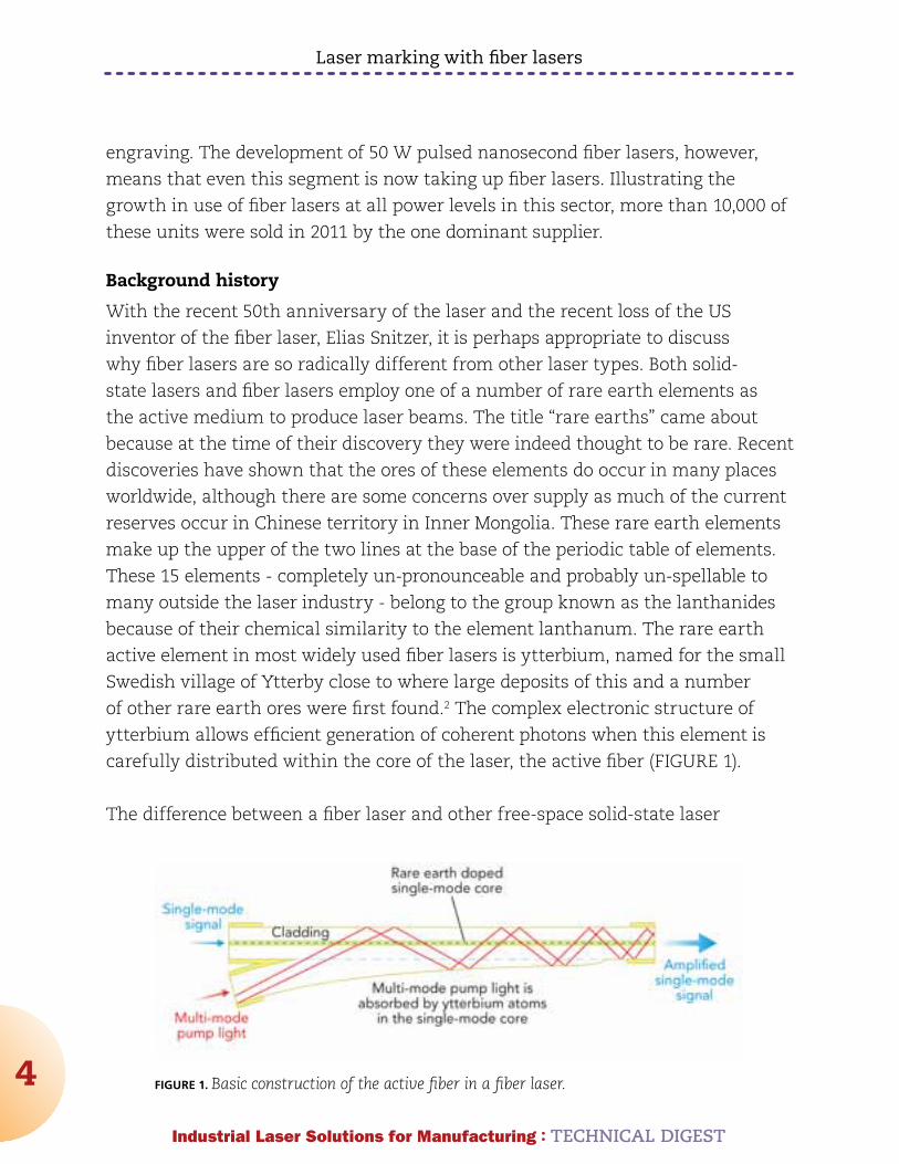
of other rare earth ores were first found.2 The complex electronic structure of
ytterbium allows efficient generation of coherent photons when this element is
carefully distributed within the core of the laser, the active fiber (FIGURE 1).
The difference between a fiber laser and other free-space solid-state laser
FIGURE 1. Basic construction of the active fiber in a fiber laser.
Laser marking with fiber lasers
5
Industrial Laser Solutions for Manufacturing : TECHnICAL DIGEST
technologies are widely misunderstood and sometimes misrepresented. In a fiber
laser the beam is actually generated within the fiber. In other technologies, the
beam is generated in free space and is then squeezed into a fiber-optic cable to be
delivered to the workpiece.
Wavelengths for laser marking
It has been well known for many years that at near-infrared wavelengths,
metal reflectivity is significantly lower than at the longer emission wavelengths
of carbon dioxide gas lasers at 10.6 μm. A second benefit of using shorter
wavelengths is that the divergence of a laser beam is proportional to its
wavelength and inversely proportional to the diameter of the beam, summarized
in the equation below:
Θ = λ/(πω)
where Θ = beam divergence, λ = laser wavelength, and ω = beam waist.
So, shorter wavelengths allow smaller focused spots and hence smaller surface
features. Despite these focusability limitations, longer-wavelength far-infrared
gas lasers still retain a strong position within the marking industry, because
many widely marked materials such as paper and thin-film optically transparent
polymers simply do not absorb enough of the laser beam. This absorption is
required to generate localized features on the surface that are visible to the
unaided human eye.
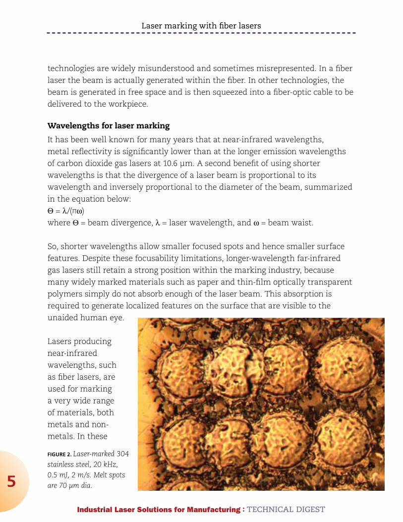
Lasers producing
near-infrared
wavelengths, such
as fiber lasers, are
used for marking
a very wide range
of materials, both
metals and non-
metals. In these
FIGURE 2. Laser-marked 304 stainless steel, 20 kHz, 0.5 mJ, 2 m/s. Melt spots are 70 μm dia.

Laser marking with fiber lasers
6
Industrial Laser Solutions for Manufacturing : TECHnICAL DIGEST
cases, marks that must be visible by the un-aided eye are created either by
ablating material or by creating oxide layers on the surface, or by a combination
of both of these. An ablative mark might appear very precise to the un-aided eye,
but examined under higher magnification one can usually see evidence of the
small-scale but very dynamic and energetic heating and vaporization processes
that are occurring. Although most of these features cannot be resolved by the un-
aided eye and are so shallow as to not affect the functionality of the component
in most circumstances, the slightly roughened edges are probably responsible for
light scattering and hence making the mark visible (FIGURE 2).
Many polymers can also be laser-marked by inducing a range of surface effects
such as foaming, carbonization, and ablation. For marking lighter-colored
polymers, thin polymer films, or semiconductor materials such as silicon when
small features are required, even better absorption may be necessary - although
the reasons for this are beyond the scope of this article, in some cases shorter
wavelength lasers in the visible spectrum are used.
What can laser marking systems do?
Laser marking system manufacturers all use very sophisticated commercially
available laser marking software to control the galvanometer scanners that
produce relative motion between the laser spot and the workpiece. It is the laser
and the optics at the heart of the machine, however, that control the marking
mechanisms the system can produce. These marks can be almost infinite
combinations of characters and graphics, logos, unique serialized alphanumerics,
or one of a number of different barcode designs. There are many justifications
for this: traceability, anti-counterfeiting, material, batch or manufacturer
identification. The primary function of all marks is they must be readable, either
by machine or by the unaided eye. Other secondary requirements may be:
:: The functionality of the part must not be compromised throughout its lifetime
in any way - for example, it should not mechanically weaken or cause corrosion
of the part;
:: The mark must endure for the lifetime of the part; and
:: The mark must be aesthetically pleasing.
The sophistication of laser marking systems make the marking process look

Laser marking with fiber lasers
7
Industrial Laser Solutions for Manufacturing : TECHnICAL DIGEST
very simple, but laser marking software allows many different approaches to
producing an optimized mark on a particular surface. A range of scan speeds,
scan line overlaps, scan patterns, and laser delays are available, and different
operators may use very different approaches to achieve a similar mark. This tells
us that laser marking is still something of a “black art” - although some general
rules can be applied, a great deal of laser marking is still experientially based.
Technical benefits of fiber lasers
One major benefit of ytterbium-doped fiber lasers is that the near-infrared
1070 nm wavelength emitted is close enough to the 1064 nm wavelength of
neodymium-doped Yttrium aluminum garnet (Nd:YAG) lasers as to make no
difference during the actual process of laser marking. This made for a relatively
easy replacement of continuous wave Nd:YAG lasers by fiber lasers for most
marking applications. This early success exposed the marking industry to fiber
lasers and their many additional benefits became better understood. This led, in
turn, to more advanced applications where fiber lasers were able to challenge the
still relatively new diode-pumped solid-state laser technology.
Another often unappreciated aspect of fiber lasers is that the whole optical
path of the laser is fully maintained and hermetically sealed within zero-loss
fully coated optical fibers - it must be made this way when the optical fibers are
produced. The continuous optical path is achieved by combining all of the fiber-
based optical components using advanced optical fiber splicing techniques. This
approach has enormous benefits and is unlike any other laser technology, in that
no optical misalignment is possible until the laser beam exits into the focusing
optics. Another related aspect is that in principle it is very simple to generate
higher average power; one simply uses longer active fibers or additional fiber
amplifier stages with more pump diodes. Of course, this scaling simply cannot
be achieved without an in-depth understanding of the science and technology of
fiber lasers, which in turn leads to an understanding of precisely where damaging
optical effects such as Raman scattering will occur and can be avoided.
Ablation rates using 50 W nanosecond fiber laser for percussion drilling 0.6 mm thick 304 stainless steel.
Laser marking with fiber lasers
8
Industrial Laser Solutions for Manufacturing : TECHnICAL DIGEST
Fixed or variable pulse length nanosecond fiber lasers
Both fixed and variable pulse length nanosecond lasers have been used
extensively for laser marking, and the simplicity, ruggedness, and cost-
effectiveness of fixed pulse length fiber lasers has, as we have seen, allowed
significant market penetration. There are, however, a limited number of
circumstances where the added flexibility of a shorter laser pulse can provide
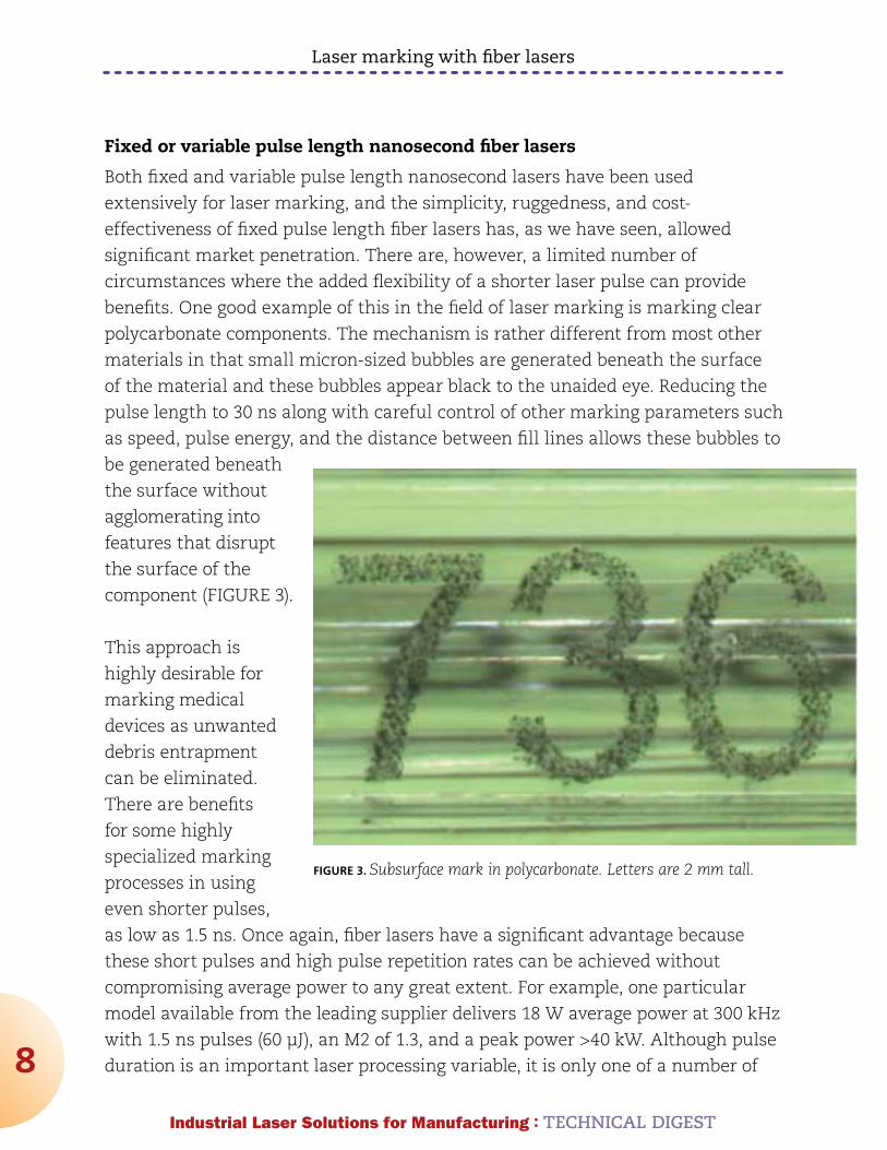
benefits. One good example of this in the field of laser marking is marking clear
polycarbonate components. The mechanism is rather different from most other
materials in that small micron-sized bubbles are generated beneath the surface
of the material and these bubbles appear black to the unaided eye. Reducing the
pulse length to 30 ns along with careful control of other marking parameters such
as speed, pulse energy, and the distance between fill lines allows these bubbles to
be generated beneath
the surface without
agglomerating into
features that disrupt
the surface of the
component (FIGURE 3).
This approach is
highly desirable for
marking medical
devices as unwanted
debris entrapment
can be eliminated.
There are benefits
for some highly
specialized marking
processes in using
even shorter pulses,
as low as 1.5 ns. Once again, fiber lasers have a significant advantage because
these short pulses and high pulse repetition rates can be achieved without
compromising average power to any great extent. For example, one particular
model available from the leading supplier delivers 18 W average power at 300 kHz
with 1.5 ns pulses (60 μJ), an M2 of 1.3, and a peak power >40 kW. Although pulse
duration is an important laser processing variable, it is only one of a number of
FIGURE 3. Subsurface mark in polycarbonate. Letters are 2 mm tall.

Laser marking with fiber lasers
9
Industrial Laser Solutions for Manufacturing : TECHnICAL DIGEST
factors that contribute to producing a particular feature size. This parameter
combination allows off-the-shelf infrared fiber lasers to produce feature sizes
with conventional optics that have only previously been obtainable using more
complex and costly shorter wavelength diode-pumped solid-state lasers.
What does higher average power do for laser marking?
Because of the complex nature of the phenomena involved in laser marking, it
is difficult to predict whether marking speed or marking depth will double by
doubling the power of the laser. In most cases, however, a higher average power
laser will allow users to mark either faster or deeper, or a combination of both. For
applications where a significant depth to the mark is required, 30 W or even 50
W lasers have been developed without any increase in footprint and without any
compromise in the focusability (or brightness) of the laser. The results shown in the
table above were gathered during percussion drilling experiments with a 50 W fiber
laser. Although this is the best possible case for material removal (the mechanism
that is observed when deep engraving metals), removal rates as high as 5 mm3/s
have been measured. It should be noted that using a higher average power laser
translates directly into a higher heat input to the part, and distortion on thinner
components may well limit the average power that can be used. When mark depth
is >100 μm, these marks retain their readability even after serious abuse of metal
surfaces; this may be deemed “tamper evident” in that a significant amount of
adjacent material needs to be removed to render the mark illegible.
mid infrared-wavelength fiber lasers
There are a number of other rare earth elements from the same Lanthanides
group in which ytterbium resides that have been used as active media in solid-
state lasers to generate alternative wavelengths. Holmium (Ho,) erbium (Er,)
and thulium (Tm) are all adjacent to each other in the periodic table, and all of
these have been used for some years in fiber lasers for various non-industrial
laser applications such as laser surgery, largely due to the high absorption of this
wavelength by H2O. Thulium fiber lasers emitting longer wavelength beams (in
the spectral region of 1900-2010 nm) have now been developed to very high power
levels (>100 W) for melting processes such as polymer welding due to their higher
volumetric absorption in unfilled polymers. These lasers are not yet available
at power levels in the pulsed nanosecond regime to be of interest to the laser
marking industry, but they will be available in the not-too-distant future.

Laser marking with fiber lasers
10
Industrial Laser Solutions for Manufacturing : TECHnICAL DIGEST
summary
It is quite a technological leap from using fiber optic cables to simply guide near-
infrared laser beams, to both generating and guiding the beam using all fiber
optics - but the benefits of combining these functions are now obvious for all to
see. As one well-known manufacturer of laser marking systems told me recently:
“The reason we love these lasers is simple; we take them out of the box, we plug
them in, we test the system, we ship it straight out of the door, and we never see
them again.” What more can be said!
references:1. David A Belforte, “2011 Annual Economic Review and Forecast”, Industrial Laser
Solutions, January 2012.
2. Sam Kean, “ The Disappearing Spoon”, Back Bay Books, ISBN 978-0-316-05164-7.
Dr. TOny HOuLT ([email protected]) is the general manager of West
Coast operations for IPG Photonics, Santa Clara, CA. He is also an Editorial
Advisor to Industrial Laser Solutions and a frequent and valued contributor to this
publication.
Industrial Laser Solutions for Manufacturing : TECHNICAL DIGEST
11
Fiber laser technology broadens out
Mid-infrared laser wavelengths open up new processes
by TOny HOuLT
THe TeLeCom CrAsH in the late 1990s can be seen in hindsight as
a pivotal event in the history of industrial lasers; from it emerged
industrial fiber laser technology. The existence at that time of in-
depth scientific and engineering expertise in active fibers and fiber
amplifiers, combined with the availability of an extensive toolkit of components,
enabled a brisk scaling-up of laser power into the multi-kilowatt regime.
The industry’s shift to fiber laser technology is now challenging well-established
lasers in many sectors of the industry. CO2 and Nd:YAG laser technologies are
now almost 50 years old, but the huge success of this new technology comes as
no surprise to those who have worked with both the old and the new. The major
impacts have been in multi-kilowatt metal processing and in low-power general-
purpose laser marking, but there is also rapid progress in other areas. The
following presents the emergence of a new process for a new class of mid infrared
longer wavelength fiber lasers.
While the differences between a CO2 gas laser and a fiber laser are obvious and
these two technologies cannot be confused, the difference between a fiber laser
and a fiber-delivered laser is not always immediately apparent. The technology
change comes from generating the beam within the fiber itself, and the inclusion
of other optical fiber components within the same continuous hermetically
sealed fiber-optic beam path. This contrasts with fiber-delivered lasers, where the
beam is generated by an array of solid-state optical crystals and discrete optical
components and is delivered to the workpiece via fiber for only the final part of
its journey. The fiber laser is produced by constructing continuous beam paths
Fiber laser technology broadens out
12
Industrial Laser Solutions for Manufacturing : TECHnICAL DIGEST
within fibers; these are
very familiar techniques
for those in the fiber
optics industry. This
fit-and-forget process
is at the heart of the
success of the fiber laser,
as it removes the need
for maintenance issues
associated with other
types of industrial lasers.
Fiber lasers in the mid infrared
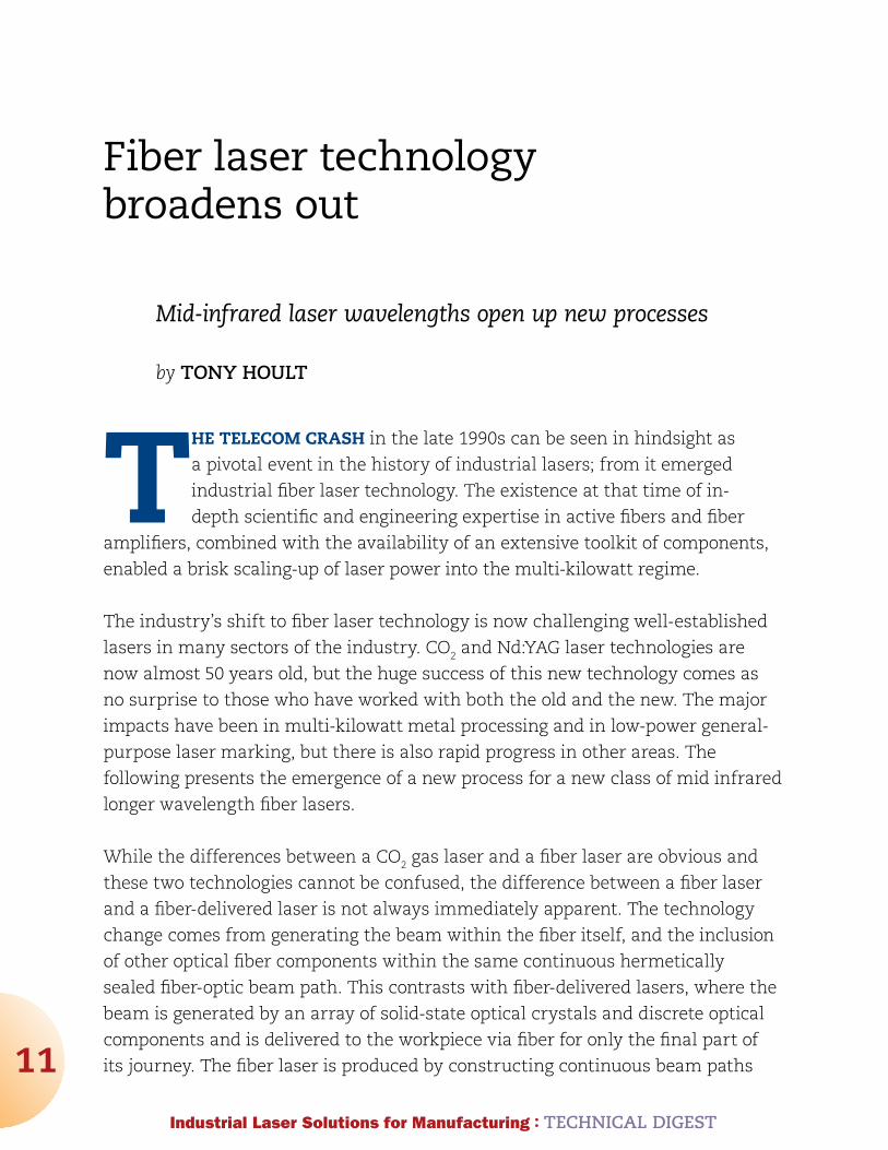
The infrared portion
of the electromagnetic
spectrum is usually divided
into three regions; the near-
, mid-, and far-infrared (FIGURE 1).1 Our concern here is with the higher-energy
near-IR regime, approximately 0.8–2.5 μm wavelength. Laser scientists are
familiar with CO2 lasers where electromagnetic bonds between atoms are seen
as quantum mechanical springs — for example, the asymmetric vibrational state
of the CO2 molecule is close to the stretching state of the N2 molecule, so energy
exchange between the two molecules occurs and lasing in the far IR occurs.
Mid-IR wavelengths are part of the fiber laser story, and thulium was seen very
early on as a candidate rare-earth ion dopant for fiber lasers, because the many
Tm 3+ transitions allow a wide range of useful wavelengths to be generated
using silica-based fibers in the 2 μm spectral region. Strong absorbance by
water occurring around this wavelength led to an early interest in thulium fiber
lasers for superficial tissue ablation with minimum coagulation depth, a form of
“bloodless surgery.” Many other non-materials-processing applications have led to
the availability of a range of optics for these wavelengths.
It has been known from previous work2 and from spectroscopic data that many
polymer matrices absorb more efficiently at this wavelength, but the reason why
FIGURE 1. IR wavelength ranges and water absorption peak vs. wavelength.1
Fiber laser technology broadens out
13
Industrial Laser Solutions for Manufacturing : TECHnICAL DIGEST
is not immediately clear. In this
mid-IR range, the spectra from even
the simplest polymer materials
are complicated by numerous
vibrational modes and are not
simple symmetrical peaks. The
wavelength equivalent for a C-H
bond absorption peak is typically
3225 nm, well away from the range
of the thulium laser. The energy
transitions in the stretch vibrational
states of these C-H molecular
bonds in high-density polyethylene
(HDPE), for example, are therefore
small compared to the binding energy of electrons in a carbon atom. It appears,
however, that the prominent absorption closest to 1940 nm is the first overtone
of the prominent fundamental C-H stretching absorption at 1724 nm. Having said
that, mid-IR developments are underway and 3225 nm laser wavelengths are now
becoming available. This will be an interesting area for future work.
With the availability of much higher average power at these wavelengths and the
high water absorption, please ensure relevant safety standards are followed for
guidance. Even the phrase ‘less unsafe’ perhaps should not be used!
Thulium fiber lasers for polymer welding
Although 50 W average power thulium fiber lasers have been commercially
available for several years, recent developments have pushed average power
to >100 W while still maintaining a high-brightness single-mode beam, with a
power level and $/W cost appropriate for high-volume manufacturing processes.
The existing through-transmission laser welding (TTLW) technique gaining
acceptance within industry only allows lap joints with one absorbing and one
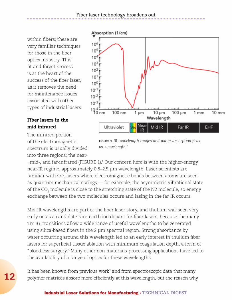
FIGURE 2. Outline of weld volume, 22 layers of 0.1 mm thick virgin LDPE.
Fiber laser technology broadens out
14
Industrial Laser Solutions for Manufacturing : TECHnICAL DIGEST
transmitting component to be welded. Also, as it employs a near-IR laser, it
is unable to weld clear-to-clear polymers unless an additive is used, such as
Clearweld infrared dye, and this can make the laser process unacceptable.
preliminary trials
Trials were conducted to confirm the improved absorption levels of a 1940 nm
thulium fiber laser beam on many thermoplastics; results on polycarbonate
(PC) are reported below. Using a 4.2 mm diameter collimated beam, power was
maintained below 5 W to ensure no significant heating or melting.
This data shows that 10%–45% absorption occurs volumetrically in this clear
sheet material depending on sample thickness. These results can be compared
with those from a commercially available transmission tester that uses a 0.8 mW
diode laser source at 850 nm, which showed >92% transmission on all samples.
As heat input to the sample is increased incrementally and by exercising careful
control over the temporal and spatial characteristics of the beam, melting occurs in
a highly controllable manner in materials up to 6 mm thick. A simple lap joint with
very basic clamping was all that was then required to produce optically clear spot
welds between two faying surfaces of like thermoplastics. Relative motion between
the laser beam and the
melt zone produced linear
welds, controlling relative
speed and power (line
energy) penetration in
a manner analogous to
welding of metals.
The cross section of the
multi-layer joint in low-
density polyethylene
(LDPE, FIGURE 2) was
prepared as a simple way
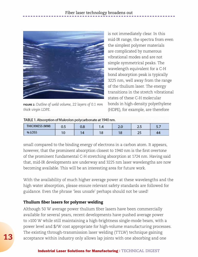
FIGURE 3. Material failure surface at interface of 3 mm diameter PC spot weld.
Fiber laser technology broadens out
15
Industrial Laser Solutions for Manufacturing : TECHnICAL DIGEST
of delineating the melt
zone. In polymers this is
more difficult than for
metals, where conventional
metallography can be
employed. As with all
welds, strength depends
largely on the weld area
at the interface, and
mechanical testing has
shown that joint strengths
greater than the strength
of the parent material
can be readily produced.
FIGURE 3 shows a spot
weld fracture surface
in polycarbonate where
cohesive material failure
has occurred.
discussion
FIGURE 2 clearly shows
the volumetric absorption
of the laser beam in
multiple thicknesses of
LDPE, which serves two
purposes: it shows layers
of polyethylene joined
together by a high-quality
weld, and clearly outlines
the melt zone confirming
volumetric absorption, as expected from a consideration of Beer’s Law. The classic
derivation of this law divides the absorbing sample into thin slices perpendicular
to the beam, and tells us that light from each subsequent slice is slightly less
intense. For a parallel beam of a specific wavelength of monochromatic radiation
passing through a homogeneous solid material, the loss of radiant intensity (ΔI)
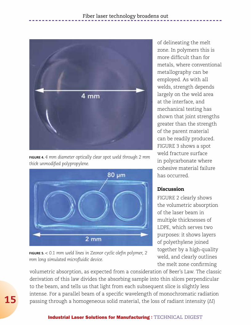
FIGURE 4. 4 mm diameter optically clear spot weld through 2 mm thick unmodified polypropylene.
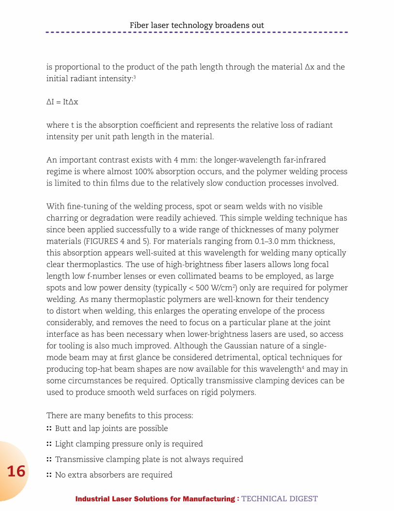
FIGURE 5. < 0.1 mm weld lines in Zeonor cyclic olefin polymer, 2 mm long simulated microfluidic device.
Fiber laser technology broadens out
16
Industrial Laser Solutions for Manufacturing : TECHnICAL DIGEST
is proportional to the product of the path length through the material Δx and the
initial radiant intensity:3
ΔI = ItΔx
where t is the absorption coefficient and represents the relative loss of radiant
intensity per unit path length in the material.
An important contrast exists with 4 mm: the longer-wavelength far-infrared
regime is where almost 100% absorption occurs, and the polymer welding process
is limited to thin films due to the relatively slow conduction processes involved.
With fine-tuning of the welding process, spot or seam welds with no visible
charring or degradation were readily achieved. This simple welding technique has
since been applied successfully to a wide range of thicknesses of many polymer
materials (FIGURES 4 and 5). For materials ranging from 0.1–3.0 mm thickness,
this absorption appears well-suited at this wavelength for welding many optically
clear thermoplastics. The use of high-brightness fiber lasers allows long focal
length low f-number lenses or even collimated beams to be employed, as large
spots and low power density (typically < 500 W/cm2) only are required for polymer
welding. As many thermoplastic polymers are well-known for their tendency
to distort when welding, this enlarges the operating envelope of the process
considerably, and removes the need to focus on a particular plane at the joint
interface as has been necessary when lower-brightness lasers are used, so access
for tooling is also much improved. Although the Gaussian nature of a single-
mode beam may at first glance be considered detrimental, optical techniques for
producing top-hat beam shapes are now available for this wavelength4 and may in
some circumstances be required. Optically transmissive clamping devices can be
used to produce smooth weld surfaces on rigid polymers.
There are many benefits to this process:
:: Butt and lap joints are possible
:: Light clamping pressure only is required
:: Transmissive clamping plate is not always required
:: No extra absorbers are required
Fiber laser technology broadens out
17
Industrial Laser Solutions for Manufacturing : TECHnICAL DIGEST
:: Optically clear defect-free welds are readily obtained
:: Low-heat-input, sub-0.1 mm wide weld features are achieved
:: Long focal length lenses or collimated beams rule out access issues.
What may turn out to be most important of all is that this new laser wavelength
allows a far greater temporal and spatial control of heat input into polymers
than has previously been possible — this may well have some very interesting
consequences!
summary
Fiber laser technology has broadened out into many sectors of the laser materials
processing industry. Multi-kilowatt fiber lasers compete with other laser
technologies, fiber laser powered marking systems now dominate general purpose
marking, new quasi-continuous wave (QCW) fiber lasers replace flash lamp-
pumped solid state lasers, low-nanosecond pulsed lasers are now established
and sub-nanosecond lasers are under development, and fiber laser components
already are widely employed in the pico and femto-second regime. With mid-
infrared laser wavelengths opening up new processes such as that reported here,
this trend looks set to continue apace.
references1. en.wikipedia.org/wiki/Electromagnetic_absorption_by_water
2. Boglea A, Rosner A, Olowinsky A. “New perspectives for the absorber free laser welding of thermoplastics,” Proc. ICALEO 2010, Anaheim, CA, USA
3. www.lepla.org/en/modules/Activities/m17/m17-theo.htm
4. Laskin A, “Beam shaping? Easy!” Industrial Laser Solutions, July 2006, p17- 19
Dr. TOny HOuLT ([email protected]) is general manager of West Coast
operations at IPG Photonics, Santa Clara, CA.

Industrial Laser Solutions for Manufacturing : TECHNICAL DIGEST
18
Drilling with fiber lasers
Pulse fiber lasers lessen acquisition and operating costs
by JEnS DIETrICH and InGOMAr KELBASSA
CompAnIes THAT use laser sources for drilling have three
requirements: cost efficiency, high productivity, and high quality.
Cost efficiency is affected by productivity and quality, but is also
determined by the operating and maintenance costs of the laser
source. Quality is the compliance with specifications such as geometrical
tolerances or metallurgical results, e.g., recast layer thickness. Productivity is the
number of holes that are drilled per time.
The type of laser source used for drilling is not important as long as all three
main objectives are achieved. Therefore, companies will use new laser sources if
they have benefits in cost efficiency, productivity, or quality compared to state-of-
the-art flashlamp-pumped Nd:YAG lasers.
New diode-pumped lasers such as fiber lasers seem to have benefits considering
their specifications; costs of the laser sources with a mean power of less than 1
kW, and operating costs are smaller.
Smaller operating costs also result from a higher electrical efficiency, a greater
lifetime of diodes compared to flashlamps, and the omission of adjustment.
When using a flashlamp-pumped laser source, the beam is guided by mirrors
that need to be adjusted and have a small loss of power (0.2 to 5% per mirror).
Using a fiber laser, the beam delivery system does not need to be adjusted as
the beam is guided by a flexible fiber. The loss of power of the beam delivery
system is rather small as no mirrors are used. Fibers as a beam delivery system
are more flexible as the beam can be delivered to different work stations by
beam switches or fiber replugging.

Drilling with fiber lasers
19
Industrial Laser Solutions for Manufacturing : TECHnICAL DIGEST
Fiber lasers can
provide a smaller
beam parameter
product at high mean
powers compared to
flashlamp-pumped
Nd:YAG lasers (FIGURE
1) as fiber lasers
have a smaller beam
parameter product in
the range above 100
W. Below 100 W, single
mode fiber lasers have
a comparable beam
parameter product of
~0.35.
Thus, drilling
with fiber lasers is applicable when quality and productivity is comparable to
flashlamp-pumped Nd:YAG lasers as fiber lasers offer more cost-savings.
Editor’s note: In this article, the authors refer to the fiber laser as a diode-pumped laser.
experimental setup
The suitability of the two different laser types for drilling – flashlamp and diode-
pumped laser – is analyzed by comparing drilling results. Therefore, geometrical
specifications of holes to be drilled are defined. The geometry is based on typical
venting holes that are drilled in tool forms. The exit diameters of through holes
are supposed to be 120 µm with a depth of 5 mm in stainless steel 1.4301. In some
cases, tool forms can have several thousands of holes. Therefore, high productivity
is needed to reduce manufacturing time. The hole quality, such as recast layer
thickness or taper, is not specified but is considered to be as high as possible.
In the experiments, a flashlamp-pumped Nd:YAG laser LASAG FLS 652N and
a pulsed fiber laser IPG YLS-600/6000-QCW with a 50 µm fiber are used. The
focal length of both optics is 100 mm. With these drilling optics, the focal
FIGURE 1. A beam parameter product as a function of the mean power of different laser sources1.
Drilling with fiber lasers
20
Industrial Laser Solutions for Manufacturing : TECHnICAL DIGEST
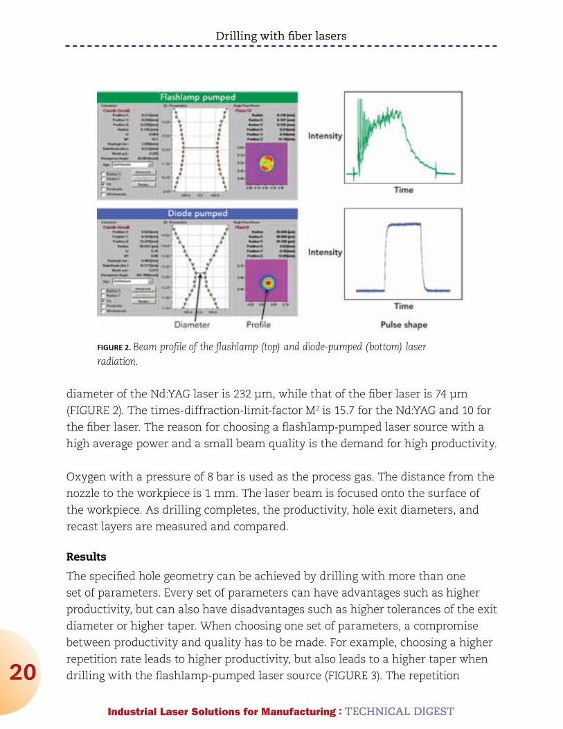
diameter of the Nd:YAG laser is 232 µm, while that of the fiber laser is 74 µm
(FIGURE 2). The times-diffraction-limit-factor M2 is 15.7 for the Nd:YAG and 10 for
the fiber laser. The reason for choosing a flashlamp-pumped laser source with a
high average power and a small beam quality is the demand for high productivity.
Oxygen with a pressure of 8 bar is used as the process gas. The distance from the
nozzle to the workpiece is 1 mm. The laser beam is focused onto the surface of
the workpiece. As drilling completes, the productivity, hole exit diameters, and
recast layers are measured and compared.
results
The specified hole geometry can be achieved by drilling with more than one
set of parameters. Every set of parameters can have advantages such as higher
productivity, but can also have disadvantages such as higher tolerances of the exit
diameter or higher taper. When choosing one set of parameters, a compromise
between productivity and quality has to be made. For example, choosing a higher
repetition rate leads to higher productivity, but also leads to a higher taper when
drilling with the flashlamp-pumped laser source (FIGURE 3). The repetition
FIGURE 2. Beam profile of the flashlamp (top) and diode-pumped (bottom) laser radiation.

Drilling with fiber lasers
21
Industrial Laser Solutions for Manufacturing : TECHnICAL DIGEST
rate of the flashlamp-pumped laser source is fixed to 40 Hz as the entrance
diameter of the hole becomes very large at higher repetition rates.
In the case of drilling with the diode-pumped laser source, the influence of the
repetition rate on taper is small (FIGURE 4). When drilling with a repetition rate
higher than 100
Hz, the taper is
almost constant,
but the holes are
enlarged in the
middle (barreling).
The standard
deviation of hole
diameters also
FIGURE 3. Longitudinal sections of holes drilled with the flashlamp-pumped laser varying the repetition rate (left) and entrance and exit diameters as a function of the repetition rate (right).
FIGURE 4. Hole geometries as a function of the repetition rate using the diode-pumped laser.
Drilling with fiber lasers
22
Industrial Laser Solutions for Manufacturing : TECHnICAL DIGEST
increases at repetition rates higher than 100 Hz. Thus, the repetition rate when
drilling with the fiber laser is fixed to 100 Hz. Both repetition rates are maximized
in order to have a high productivity with a reasonable geometric quality such as
taper.
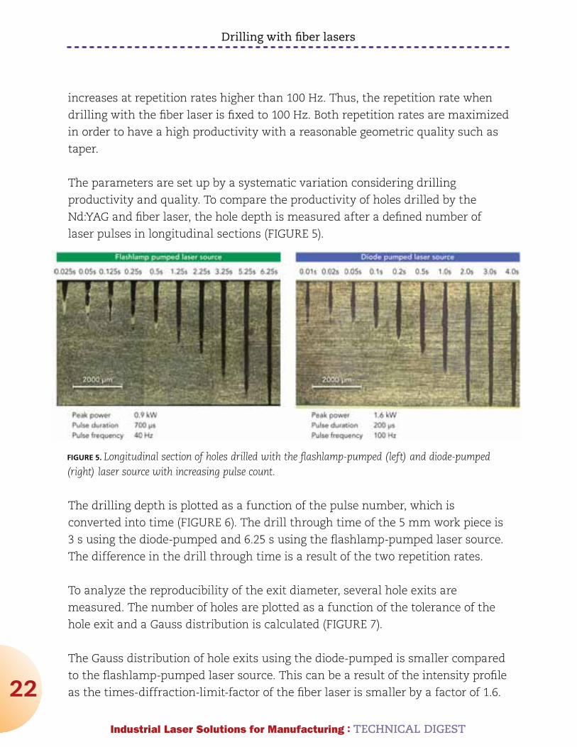
The parameters are set up by a systematic variation considering drilling
productivity and quality. To compare the productivity of holes drilled by the
Nd:YAG and fiber laser, the hole depth is measured after a defined number of
laser pulses in longitudinal sections (FIGURE 5).
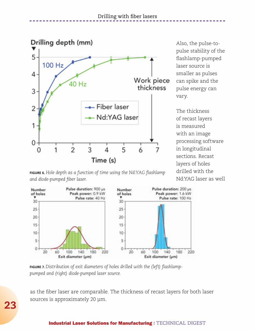
The drilling depth is plotted as a function of the pulse number, which is
converted into time (FIGURE 6). The drill through time of the 5 mm work piece is
3 s using the diode-pumped and 6.25 s using the flashlamp-pumped laser source.
The difference in the drill through time is a result of the two repetition rates.
To analyze the reproducibility of the exit diameter, several hole exits are
measured. The number of holes are plotted as a function of the tolerance of the
hole exit and a Gauss distribution is calculated (FIGURE 7).
The Gauss distribution of hole exits using the diode-pumped is smaller compared
to the flashlamp-pumped laser source. This can be a result of the intensity profile
as the times-diffraction-limit-factor of the fiber laser is smaller by a factor of 1.6.
FIGURE 5. Longitudinal section of holes drilled with the flashlamp-pumped (left) and diode-pumped (right) laser source with increasing pulse count.
Drilling with fiber lasers
23
Industrial Laser Solutions for Manufacturing : TECHnICAL DIGEST
Also, the pulse-to-
pulse stability of the
flashlamp-pumped
laser source is
smaller as pulses
can spike and the
pulse energy can
vary.
The thickness
of recast layers
is measured
with an image
processing software
in longitudinal
sections. Recast
layers of holes
drilled with the
Nd:YAG laser as well
as the fiber laser are comparable. The thickness of recast layers for both laser
sources is approximately 20 µm.
FIGURE 6. Hole depth as a function of time using the Nd:YAG flashlamp and diode-pumped fiber laser.
FIGURE 7. Distribution of exit diameters of holes drilled with the (left) flashlamp-pumped and (right) diode-pumped laser source.
Drilling with fiber lasers
24
Industrial Laser Solutions for Manufacturing : TECHnICAL DIGEST
Conclusion
Pulsed fiber lasers can provide a smaller beam parameter product at high mean
powers compared to flashlamp-pumped Nd:YAG laser sources and are more
economical as acquisition costs and operating costs are less. The specified hole
geometry with a diameter of 120 µm and a depth of 5 mm in stainless steel
1.4301 can be achieved with a flashlamp as well as a diode-pumped laser source.
When drilling with both laser systems, compromises between productivity and
geometrical quality such as taper must be made. Parameters, which consider
productivity as well as quality, are determined.
The productivity using a fiber laser is higher in the experiments compared to the
Nd:YAG laser as the repetition rate of the Nd:YAG laser is smaller. The repetition
rate cannot be raised because this increases taper and the standard deviation of
hole diameters.
The tolerance of hole exit diameters is smaller when drilling with the fiber laser.
This can be a result of the smaller times-diffraction-limit-factor M2 as well as
a better pulse-to-pulse stability of fiber lasers compared to flashlamp-pumped
Nd:YAG lasers.
Drilling with flashlamp-pumped Nd:YAG lasers is still state-of-the-art. Nd:YAG
lasers are commonly used for industrial applications such as drilling, cooling
holes in turbine blades, or manufacturing holes in tool forms. There will be
economic and technical benefits using a diode-pumped laser source for drilling if
companies will change their laser sources from flashlamp-pumped Nd:YAG lasers
to diode-pumped lasers such as fiber lasers in the future.
reference1. Poprawe R, Lasertechnik für die Fertigung Berlin Heidelberg, Springer Verlag, 2005,
ISBN: 3-540-21406-2.
JEnS DIETrICH is group leader, laser drilling LLT, RWTH Aachen University and
Akad. Oberrat. InGOMAr KELBASSA is vice and academic director LLT, RWTH
Aachen University, and the department head RWTH LLT, Fraunhofer ILT, and
chair for laser technology, RWTH Aachen University, Aachen, Germany.
Industrial Laser Solutions for Manufacturing : TECHNICAL DIGEST
25
Fiber laser spot welding
by Dr. KLAuS KrASTEL
For TodAy’s HIGH volume production in the automotive industry,
resistance spot welding and laser remote welding, while well established,
present advantages and disadvantages. For laser remote welding the main
advantage is the significant cycle time reduction due to almost complete
elimination of idle times and the mechanical advantages of laser welded seams. For
resistance spot welding an advantage is the integrated clamping technology, which
comes nearly for free. IPG Laser GmbH ( www.ipgphotonics.com) has combined
these advantages in a new technology, COSY, offering the resistance spot welding
process, featuring the simplicity of clamping tools and production facilities, used in
combination with the advantages of laser welding.
A problem for some types of solid-state laser welding is operator safety, which
requires a protective housing for lasers with power up to 6 kW. When used for
welding sheet metal in the automotive industry, safety equipment with fast
reaction safety devices is necessary. This complicates their use in an open
production facility, for example in automotive body and assembly plants.
Laser welding for the production of sheet metal components in body plants offers
the following advantages:
:: Higher process speed (shorter cycle times)
:: Increased component strength by longer seams with higher torsional stiffness
:: Efforts and costs comparable to today’s modern resistance welding systems
:: Realization of high job safety requirements with reduced costs
Fiber laser welding with a suitable welding tool provides the opportunity to
accomplish all these objectives.
Fiber laser spot welding
26
Industrial Laser Solutions for Manufacturing : TECHnICAL DIGEST
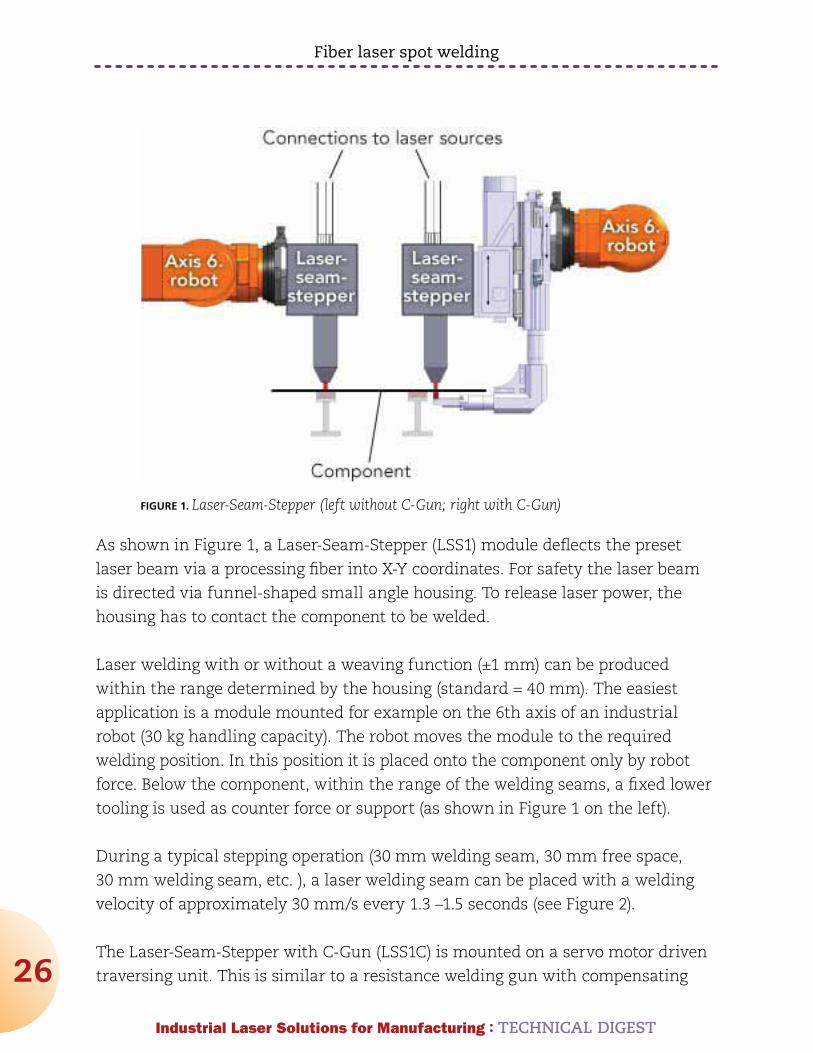
As shown in Figure 1, a Laser-Seam-Stepper (LSS1) module deflects the preset
laser beam via a processing fiber into X-Y coordinates. For safety the laser beam
is directed via funnel-shaped small angle housing. To release laser power, the
housing has to contact the component to be welded.
Laser welding with or without a weaving function (±1 mm) can be produced
within the range determined by the housing (standard = 40 mm). The easiest
application is a module mounted for example on the 6th axis of an industrial
robot (30 kg handling capacity). The robot moves the module to the required
welding position. In this position it is placed onto the component only by robot
force. Below the component, within the range of the welding seams, a fixed lower
tooling is used as counter force or support (as shown in Figure 1 on the left).
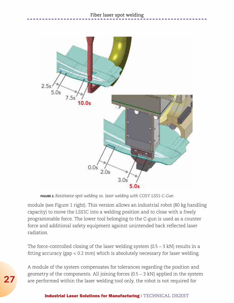
During a typical stepping operation (30 mm welding seam, 30 mm free space,
30 mm welding seam, etc. ), a laser welding seam can be placed with a welding
velocity of approximately 30 mm/s every 1.3 –1.5 seconds (see Figure 2).
The Laser-Seam-Stepper with C-Gun (LSS1C) is mounted on a servo motor driven
traversing unit. This is similar to a resistance welding gun with compensating
FIGURE 1. Laser-Seam-Stepper (left without C-Gun; right with C-Gun)
Fiber laser spot welding
27
Industrial Laser Solutions for Manufacturing : TECHnICAL DIGEST
module (see Figure 1 right). This version allows an industrial robot (80 kg handling
capacity) to move the LSS1C into a welding position and to close with a freely
programmable force. The lower tool belonging to the C-gun is used as a counter
force and additional safety equipment against unintended back reflected laser
radiation.
The force-controlled closing of the laser welding system (0.5 – 3 kN) results in a
fitting accuracy (gap < 0.2 mm) which is absolutely necessary for laser welding.
A module of the system compensates for tolerances regarding the position and
geometry of the components. All joining forces (0.5 – 3 kN) applied in the system
are performed within the laser welding tool only, the robot is not required for
FIGURE 2. Resistance spot welding vs. laser welding with COSY LSS1-C-Gun
Fiber laser spot welding
28
Industrial Laser Solutions for Manufacturing : TECHnICAL DIGEST
these joining forces. During a typical stepping operation a laser seam can be
placed every 1.7 – 2 seconds.
Features of the laser welding tools, COSY LSS1/LLS1C, with a compact IPG fiber
laser are:
:: The mechanically compact design of the basic unit COSY-LSS1 can be moved by
an industrial robot with a handling capacity of 30 kg.
:: The basic version enables the system to weld linear seams with a maximum
length of 40 mm.
:: Optionally a weaving function (3 – 30 Hz) can be switched on in order to spread
the welding seam (2 mm).
:: Laser sources are very compact fiber laser systems with power between 500 W
and 3 kW and a total efficiency of more than 30 %.
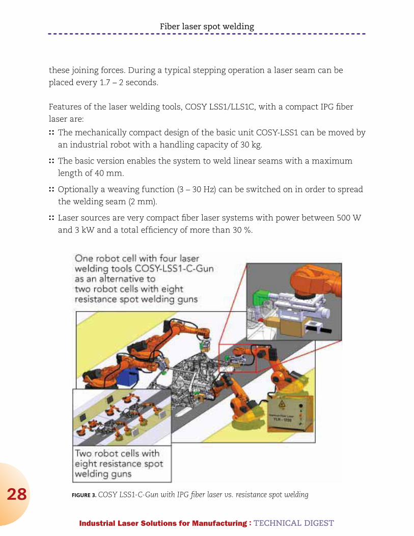
FIGURE 3. COSY LSS1-C-Gun with IPG fiber laser vs. resistance spot welding

Fiber laser spot welding
29
Industrial Laser Solutions for Manufacturing : TECHnICAL DIGEST
:: The fiber laser and the welding head are maintenance free.
:: The system is laser safe and can be used without complex laser protection
housings. (Protective equipment as used in robot spot and arc welding cells is
sufficient.)
:: The LLS1C can join the sheet metal plates to be welded with a defined force in
the area of the welding seam. This process reduces the normally high clamping
effort during laser welding.
:: The system is controlled via hardware interlock or buss systems. In the easiest
case preconfigured seams of 10 mm – 40 mm seam length, including welding
speed and laser power can be selected and started.
Typical applications for this system are sheet metal assemblies in the body-in-
white production lines (see Figure 3), which up to now have been joined with
many resistance welding spots. The intention of the COSY-LSS1and COSY-LSS1-C-
Gun is to replace two welding spots with a typical distance of approximately 30
mm by one laser step seam of approximately 30 mm.
For example in the case of 30 resistance spot welds the cycle time is
approximately 75 seconds. If spot welding is replaced by laser welding in the
manner described, only 15 laser weld seams are required. The cycle time can be
reduced down to only 37 seconds in total, as well as the required floor space.
Dr. KLAuS KrASTEL ([email protected]) is with IPG Laser GmbH
www.ipgphotonics.com.
30
Industrial Laser Solutions for Manufacturing : TECHNICAL DIGEST
Company Description:IPG Photonics is the world leader in high-power fiber lasers & amplifiers. IPG manufactures active fiber lasers, direct diodes and amplifiers operating at 0.5–2 microns. Industrial lasers operating at 1 micron are available from 10 watts to >50 kilowatts for use in a wide range of applications such as materials processing, telecommunications, medical and other advanced applications. These devices feature low beam divergence, air cooling, high electrical efficiency, a compact, rugged package and unparalleled diode life.
www.IPGPhotonics.com
C
M
Y
CM
MY
CY
CMY
K
080812 8.268x11.698 General Ad 3.ai 8/14/2012 5:26:24 PM