technical data model e spray nozzles vk810 - vk817 · model e spray nozzles vk810 - vk817 technical...
TRANSCRIPT
model e Spray nozzleS vk810 - vk817TeCHnICal daTa
May 17, 2013
The viking Corporation, 210 n Industrial park drive, Hastings mI 49058Telephone: 269-945-9501 Technical Services: 877-384-5464 Fax: 269-818-1680 email: [email protected]
Spray Nozzle 32a
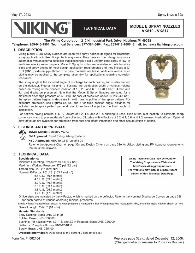
1. deSCrIpTIonViking Model E, 3D Spray Nozzles are open type spray nozzles designed for directional spray applications in fixed fire protection systems. They have an open design only (non-automatic) with an external deflector that discharges a solid uniform cone spray of low- to medium- velocity water droplets. Model E Spray Nozzles are available in multiple orifice sizes and spray angles to meet design application requirements and they include a ½” NPT (DN15) external pipe thread. The base materials are brass, while electroless nickel plating may be applied to the complete assembly for applications requiring corrosion resistance. The spray angle is the included angle of discharge for each nozzle, and is also marked on the deflector. Figures 1a and 1b illustrate the distribution width at various heights based on testing in the pendent position at 10, 20, and 60 PSI (0.7 bar, 1.4 bar, and 4.1 bar) discharge pressures. Note that the Model E Spray Nozzles are rated for a maximum discharge pressure of 175 PSI (12 bar). At pressures above 60 PSI (4.1 bar), the spray pattern begins to decrease in width due to pull-in of the spray pattern. For exposure protection, see Figures 6a, 6b, and 7 for fixed position angle, distance for included angle spray pattern perpendicular to surface of object at the fixed angle of installation. For nozzles having nominal U.S. K-Factors of 1.2, 1.8, and 2.3, a bushing is used, flush at the inlet location, to eliminate sharp corner cavity and to prevent debris from collecting. (Nozzles with K-Factors of 3.2, 4.1, 5.6, and 7.2 are machined orifices.) Optional blow-off plugs are available for protection from dust and insect infestation and other accumulation of debris.
2. lISTInGS and approvalScUlus listed: Category VGYZFm approved: Fixed Extinguishing SystemsnyC approved: MEA 89-92-E, Volume 29Refer to the Approval Chart on page 32c and Design Criteria on page 32e for cULus Listing and FM Approval requirements that must be followed.
3. TeCHnICal daTaSpecifications:Minimum Operating Pressure: 10 psi (0.7 bar) Maximum Working Pressure: 175 psi (12 bar)Thread size: 1/2” (15 mm) NPTNominal K-Factor: 7.2 U.S. (103.7 metric*)
5.6 U.S. (80.6 metric) 4.1 U.S. (59.0 metric) 3.2 U.S. (46.1 metric) 2.3 U.S. (33.1 metric) 1.8 U.S. (25.9 metric) 1.2 U.S. (17.3 metric)
Orifice sizes are indicated by the K-Factor, which is marked on the deflector. Refer to the Nominal Discharge Curves on page 32f for each nozzle at various operating residual pressures.
* Metric K-factor measurement shown is when pressure is measured in Bar. When pressure is measured in kPa, divide the metric K-factor shown by 10.0.Overall Length: 2-7/16” (61 mm) material Standards:Body Casting: Brass UNS-C84400 Splitter: Brass UNS-C36000Bushing: (for nozzles with 1.2, 1.8, and 2.3 K-Factors): Brass UNS-C36000Deflector: Phosphor Bronze UNS-C51000Screw: Brass UNS-C65100ordering Information: (Also refer to the current Viking price list.)
Form No. F_062104 Replaces page 32a-g, dated December 12, 2008. (Changed deflector material to Phosphor Bronze.)
viking Technical data may be found on The viking Corporation’s Web site at
http://www.vikinggroupinc.com.The Web site may include a more recent
edition of this Technical data page.

TeCHnICal daTa
May 17, 2013
The viking Corporation, 210 n Industrial park drive, Hastings mI 49058Telephone: 269-945-9501 Technical Services: 877-384-5464 Fax: 269-818-1680 email: [email protected]
Spray Nozzle 32b
model e Spray nozzleS vk810 - vk817
Order Model E Spray Nozzles by first selecting the appropriate base part number for the K-Factor and spray angle desired. Then add the appropriate suffix for the desired finish and the suffix “Z” for open nozzles to the spray nozzle base part number.
Finish Suffix: Brass = A, Electroless Nickel Plated = JTemperature Suffix: OPEN = ZFor example, spray nozzle VK810 with a K-Factor of 7.2 (103.7 metric) and a Brass finish = Part No. 12867AZaccessories: (Also refer to the “Sprinkler Accessories” section of the Viking data book.)Sprinkler Wrench: Part No. 10896W/B (available since 2000). Blow-off plugs (optional): Refer to technical data page 33y. Blow-off plugs are used to prevent the depositing of foreign mate-
rials in the waterway, which could interfere with the discharge of the spray nozzles. The plugs are designed to blow off when the system piping is pressurized. note: The blow-off plugs are NOT cULus Listed or FM Approved.
4. InSTallaTIonWarnInG: Viking Model E Spray Nozzles are manufactured and tested to meet the rigid requirements of the approving agency. The nozzles are designed to be installed in accordance with recognized installation standards. Deviation from the standards or any alteration to the nozzle after it leaves the factory including, but not limited to: painting, plating, coating, or modification, may render the unit inoperative and will automatically nullify the approval and any guarantee made by The Viking Corporation.The Approval Chart on page 32c shows listings and approvals of Model E Spray Nozzles for use on water spray systems and water based deluge systems. The chart shows listings and approvals available at the time of printing. Other approvals are in process. Check with the manufacturer for any additional approvals. A. Spray nozzles are to be installed in accordance with the latest edition of viking technical data, the latest published
standards of nFpa, Fm Global, lpCB, apSad, vdS or other similar organizations, and also with the provisions of gov-ernmental codes, ordinances, and standards whenever applicable. The use of model e Spray nozzles may be limited due to occupancy and hazard. refer to the authority Having Jurisdiction prior to installation.
B. Handle Model E Spray Nozzles with care. They must be stored in a cool, dry place in their original shipping container. Never install a spray nozzle that has been dropped or damaged.
C. Corrosion-resistant spray nozzles must be installed when subject to corrosive atmospheres. D. Spray nozzles must be installed after the piping is in place to prevent mechanical damage. E. Before installing, be sure to have the appropriate model and style, with the correct K-Factor and spray angle. Spray nozzle
deflectors are identified with the VK model number, nominal K-Factor, and spray angle.1. Apply a small amount of pipe-joint compound or tape to the external threads of the spray nozzle only, taking care not to allow
a build-up of compound inside the inlet.2. Install the nozzle on the fixed piping, using the special sprinkler/spray nozzle wrench only. Take care not to over-tighten or
damage the spray nozzle. DO NOT use the deflector to start or thread the unit into a fitting.F. Spray nozzles must be protected from mechanical damage. Where open spray nozzles are used, care must be taken to prevent
foreign materials from entering the orifice. Foreign materials may accumulate and restrict or plug the waterway and may prevent proper operation of the spray nozzle.
5. operaTIonModel E, 3D Spray Nozzles are designed to apply cooling water to exposed vertical, horizontal, curved, and irregular shaped sur-faces to allow cooling of objects externally when exposed to an adjacent fire. Cooling is done to prevent objects from absorbing heat that could cause structural damage and possible spread of fire to the protected object. In some applications, Model E Spray Nozzles may be applied to control or extinguish fire of the protected area (depending on water design application density).
6. InSpeCTIonS, TeSTS and maInTenanCenoTICe: The owner is responsible for maintaining the fire protection system and devices in proper operating condition. For minimum maintenance and inspection requirements, refer to the NFPA standard (e.g., NFPA 25) that describes care and maintenance of sprin-kler systems. In addition, the AHJ may have additional maintenance, testing, and inspection requirements that must be followed.A. Spray nozzles must be inspected on a regular basis for corrosion, mechanical damage, obstructions, paint, etc. Where open
spray nozzles are installed, verify that foreign materials (such as dust, dirt, etc.) DO NOT restrict or plug the waterspray. The frequency of inspections may vary due to corrosive atmospheres, water supplies, and activity around the device. It is also rec-ommended that outdoor installations of Model E Spray Nozzles with blow-off plugs be periodically inspected, during freezing weather conditions, for the presence of ice buildup from trapped condensate which could effect the proper release of the plugs.
B. Spray nozzles that have been painted or mechanically damaged must be replaced immediately. Nozzles showing signs of corrosion shall be tested and/or replaced immediately as required. When replacing spray nozzles, use only new Model E Spray Nozzles.

model e Spray nozzleS vk810 - vk817TeCHnICal daTa
May 17, 2013
The viking Corporation, 210 n Industrial park drive, Hastings mI 49058Telephone: 269-945-9501 Technical Services: 877-384-5464 Fax: 269-818-1680 email: [email protected]
Spray Nozzle 32c
1. Using the appropriate wrench, remove the old spray nozzle and install the new unit. Care must be taken to ensure that the replacement spray nozzle has the proper model, style, and K-Factor. Model E Spray Nozzle deflectors are identified with the VK model number, nominal U.S. K-Factor, and spray angle. A cabinet should be provided and stocked with a wrench and extra spray nozzles of each variety used for replacement purposes.
C. The spray nozzle discharge pattern is critical for proper fire protection. Therefore, nothing should be hung from, attached to, or oth-erwise obstruct the discharge pattern. All obstructions must be immediately removed or, if necessary, additional nozzles installed.
D. Fire protection systems that have been subjected to a fire must be returned to service as soon as possible. The entire system must be inspected for damage and repaired or replaced as necessary. Spray nozzles that have been exposed to corrosive prod-ucts of combustion or high ambient temperatures, should be replaced. Refer to the AHJ for minimum replacement requirements.
7. avaIlaBIlITyViking Model E Spray Nozzles are available through a network of domestic and international distributors. See The Viking Corporation web site for the closest distributor or contact The Viking Corporation.
8. GUaranTeeFor details of warranty, refer to Viking’s current list price schedule or contact Viking directly.

model e Spray nozzleS vk810 - vk817TeCHnICal daTa
May 17, 2013
The viking Corporation, 210 n Industrial park drive, Hastings mI 49058Telephone: 269-945-9501 Technical Services: 877-384-5464 Fax: 269-818-1680 email: [email protected]
Spray Nozzle 32d
approval Chartmodel e Spray nozzles
maximum 175 pSI (12 bar) WWp (refer also to design Criteria on page 32e.)
Base part
number1SIn2
nominal k-Factor angle
listings and approvals4
Base part
number1SIn2
nominal k-Factor angle
listings and approvals4
U.S. metric3 cUlus5 nyC6 Fm U.S. metric3 cUlus5 nyC6 Fm12867 VK810 7.2 103.7 65° Yes Yes Yes 12895 VK814 7.2 103.7 125° Yes Yes Yes
12868 VK810 5.6 80.6 65° Yes Yes Yes 12896 VK814 5.6 80.6 125° Yes Yes Yes
12869 VK810 4.1 59.0 65° Yes Yes Yes 12897 VK814 4.1 59.0 125° Yes Yes Yes
12870 VK810 3.2 46.1 65° Yes Yes Yes7 12898 VK814 3.2 46.1 125° Yes Yes Yes7
12871 VK810 2.3 33.1 65° Yes Yes Yes7 12899 VK814 2.3 33.1 125° Yes Yes Yes7
12872 VK810 1.8 25.9 65° Yes Yes Yes7 12900 VK814 1.8 25.9 125° Yes Yes Yes7
12873 VK810 1.2 17.3 65° Yes Yes Yes7 12901 VK814 1.2 17.3 125° Yes Yes Yes7
12874 VK811 7.2 103.7 80° Yes Yes Yes 12902 VK815 7.2 103.7 140° Yes Yes Yes
12875 VK811 5.6 80.6 80° Yes Yes Yes 12903 VK815 5.6 80.6 140° Yes Yes Yes
12876 VK811 4.1 59.0 80° Yes Yes Yes 12904 VK815 4.1 59.0 140° Yes Yes Yes
12877 VK811 3.2 46.1 80° Yes Yes Yes7 12905 VK815 3.2 46.1 140° Yes Yes Yes7
12878 VK811 2.3 33.1 80° Yes Yes Yes7 12906 VK815 2.3 33.1 140° Yes Yes Yes7
12879 VK811 1.8 25.9 80° Yes Yes Yes7 12907 VK815 1.8 25.9 140° Yes Yes Yes7
12880 VK811 1.2 17.3 80° Yes Yes Yes7 12908 VK815 1.2 17.3 140° Yes Yes Yes7
12881 VK812 7.2 103.7 95° Yes Yes Yes 12909 VK816 7.2 103.7 160° Yes Yes Yes
12882 VK812 5.6 80.6 95° Yes Yes Yes 12910 VK816 5.6 80.6 160° Yes Yes Yes
12883 VK812 4.1 59.0 95° Yes Yes Yes 12911 VK816 4.1 59.0 160° Yes Yes Yes
12884 VK812 3.2 46.1 95° Yes Yes Yes7 12912 VK816 3.2 46.1 160° Yes Yes Yes7
12885 VK812 2.3 33.1 95° Yes Yes Yes7 12913 VK816 2.3 33.1 160° Yes Yes Yes7
12886 VK812 1.8 25.9 95° Yes Yes Yes7 12914 VK816 1.8 25.9 160° Yes Yes Yes7
12887 VK812 1.2 17.3 95° Yes Yes Yes7 12915 VK816 1.2 17.3 160° Yes Yes Yes7
12888 VK813 7.2 103.7 110° Yes Yes Yes 12916 VK817 7.2 103.7 180° Yes Yes Yes
12889 VK813 5.6 80.6 110° Yes Yes Yes 12917 VK817 5.6 80.6 180° Yes Yes Yes
12890 VK813 4.1 59.0 110° Yes Yes Yes 12918 VK817 4.1 59.0 180° Yes Yes Yes
12891 VK813 3.2 46.1 110° Yes Yes Yes7 12919 VK817 3.2 46.1 180° Yes Yes Yes7
12892 VK813 2.3 33.1 110° Yes Yes Yes7 12920 VK817 2.3 33.1 180° Yes Yes Yes7
12893 VK813 1.8 25.9 110° Yes Yes Yes7 12921 VK817 1.8 25.9 180° Yes Yes Yes7
12894 VK813 1.2 17.3 110° Yes Yes Yes7 12922 VK817 1.2 17.3 180° Yes Yes Yes7
available Finishes: Brass or Electroless Nickel Plated8
Footnotes1 Base part number is shown. For complete part number, refer to Viking’s current price schedule.2 The spray nozzle deflector is identified with the VK model number, K-Factor, and spray angle.3 Metric K-factor shown is for use when pressure is measured in bar. When pressure is measured in kPa, divide the metric K-factor shown by 10.0. 4 This table shows the listings and approvals available at the time of printing. Check with the manufacturer for any additional approvals.5 Listed by Underwriters Laboratories Inc. for use in the U.S. and Canada.6 Accepted for use, City of New York Department of Buildings, MEA Number 89-92-E, Vol. 29.7 Orifice diameter is less than 3/8” (9.4 mm) for Model E Nozzles with K-Factors of 3.2, 2.3, 1.8, and 1.2. A pipeline strainer with a 1/8” (3.2 mm) or
less perforation is required for FM Approval.8 For corrosion resistance.

TeCHnICal daTa
May 17, 2013
The viking Corporation, 210 n Industrial park drive, Hastings mI 49058Telephone: 269-945-9501 Technical Services: 877-384-5464 Fax: 269-818-1680 email: [email protected]
Spray Nozzle 32e
model e Spray nozzleS vk810 - vk817
deSIGn CrITerIa (Also refer to the Approval Chart on page 32c.)
nozzle placementWhen the Authority Having Jurisdiction requires direct impingement of water spray of the complete protected surface, the nozzles should be spaced and directed so their spray pattern will completely cover the surface plane of the protected object or area. Use the minimum required average density based on the included angle and the K-Factor based on the residual pressure at the inlet of the nozzles. Figures 1a and 1b indicate the coverage for each nozzle’s included spray angle at various heights. Recommendation: Limit the maximum spacing of nozzles to 12 ft. (3.6 m) or less for indoor ap-plications and 10 ft. (3 m) or less for outdoor applications. For exposure protection of vessels using rundown and slippage, e.g., exposure protection of vessels per NFPA 15 section 7.4.2 (2007 edition), the preceding recommendations apply.Figures 6a and 6b indicate the distance from the nozzles to the tangent surface of the protected object at various fixed angles. The fixed angle is the included angle from pendent position being zero of spray nozzle position. The spray angle is the included angle of the spray nozzle pattern. The maxi-mum distance is determined where the spray pattern angle is unchanged at the perpendicular position to tangent of fixed angle. The distances indicated are for 20 PSI (1.4 Bar) minimum, to 60 PSI (4.1 Bar) maximum residual pressure at the inlet of the nozzles. When Viking Model E Spay Nozzles are used to protect surfaces of vessels, they should be positioned normal to the surface being protected and approximately 2 ft. (.6 m) from the surface. Using the proper spray angle and K-Factor with this approach will provide the most effective protection and minimize effects of wind or draft conditions on the water spray pattern of the nozzles.Installation precautionAs a nozzle is being installed farther from the plane of protection, the centerline that is perpendicular to the plane of protection is potentially off-set with the center/target of plane of protection due to installation error. Take extra care when locating a nozzle far from the plane of protection. Recommendation: Overlap spray patterns to provide a safety factor in the installation.notes about pressure requirements (Figures 6a & 6b)1. Working pressures of 10 to 60 PSI (.7 to 4.1 Bar) can only be applied for 0° (vertically downward) orientation.2. Working pressures for orientation angles other than 0° are 20 to 60 PSI (1.4 to 4.1 Bar).3. However, unless otherwise specified, when the nozzles are axially installed 2 ft. (.6 m) or less from the plane of protection, working pressures of 10 to 60 PSI (.7 to 4.1 Bar) can be applied on all installation angles.
Spray patternsThe design spray pattern profiles of the Model E Spray Nozzles with included spray angles of 65° to 180° are given in the graph in Figures 1a and 1b for discharge pressures from 10 to 60 PSI (.7 to 4.1 Bar). When discharge pressures above this are applied, the coverage area will decrease because the spray pattern tends to draw inward at higher pressures. When applying discharge pressures higher than 60 PSI (4.1 Bar), consult the Viking Technical Services department.In Figures 6a and 6b, the maximum axial distance between the nozzle tip and the tangential plane being protected using a fixed installation angle is given. The operating discharge pressures are 20 PSI to 60 PSI (1.4 to 4.1 Bar) for application of this data. It is recommended that overlap be applied when using nozzles for exposure protection in this method. pipline StrainersOrifice diameter is less than 3/8” (9.4 mm) for Model E Nozzles with K-Factors of 3.2, 2.3, 1.8, and 1.2. A pipeline strainer with a 1/8” (3.2 mm) or less perforation is required for FM Approval.
ImporTanT: always refer to Bulletin Form no. F_091699 - Care and Handling of Sprinklers. viking spray nozzles are to be installed in accordance with the latest edition of viking technical data, the appropriate standards of nFpa, Fm Global, lpCB, apSad, vdS or other similar organizations, and also with the provisions of governmen-tal codes, ordinances, and standards, whenever applicable.

model e Spray nozzleS vk810 - vk817TeCHnICal daTa
May 17, 2013
The viking Corporation, 210 n Industrial park drive, Hastings mI 49058Telephone: 269-945-9501 Technical Services: 877-384-5464 Fax: 269-818-1680 email: [email protected]
Spray Nozzle 32f
Figure 1a: design Spray profiles (feet) Figure 1b: design Spray profiles (meters)
noTeS:1. Design data was obtained from tests in still air.2. Design data applies to a residual (flowing) pressure range at the nozzle inlet of 10 to 60 PSI (.7 to 4.1 Bar). For pressures up to 175 PSI (12 Bar),
consult the Viking Technical Services department toll free at 1-877-384-5464. Refer to the Authority Having Jurisdiction for their minimum required residual pressure.
3. The shapes of the Design Spray Profiles remain essentially unchanged over the maximum Axial Distances shown on pages 32h-i.4. Maximum Axial Distances shown on pages 32h-i are based on exposure protection.
Figure 2: design Spray profile
TeCHnICal daTa
May 17, 2013
The viking Corporation, 210 n Industrial park drive, Hastings mI 49058Telephone: 269-945-9501 Technical Services: 877-384-5464 Fax: 269-818-1680 email: [email protected]
Spray Nozzle 32g
model e Spray nozzleS vk810 - vk817
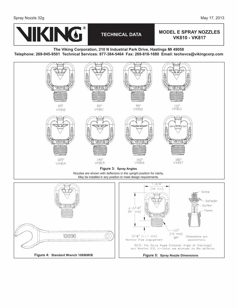
Figure 3: Spray angles Nozzles are shown with deflectors in the upright position for clarity.
May be installed in any position to meet design requirements.
Figure 4: Standard Wrench 10896W/B Figure 5: Spray nozzle dimensions
model e Spray nozzleS vk810 - vk817TeCHnICal daTa
May 17, 2013
The viking Corporation, 210 n Industrial park drive, Hastings mI 49058Telephone: 269-945-9501 Technical Services: 877-384-5464 Fax: 269-818-1680 email: [email protected]
Spray Nozzle 32h
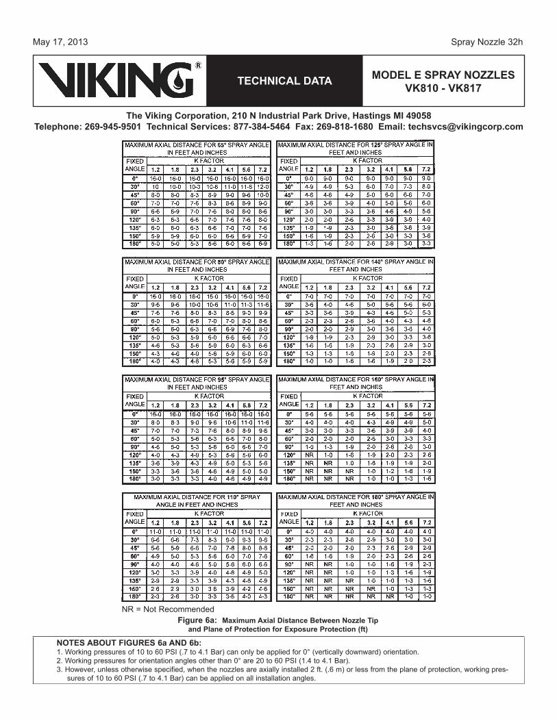
Figure 6a: maximum axial distance Between nozzle Tip and plane of protection for exposure protection (ft)
noTeS aBoUT FIGUreS 6a and 6b:1. Working pressures of 10 to 60 PSI (.7 to 4.1 Bar) can only be applied for 0° (vertically downward) orientation.2. Working pressures for orientation angles other than 0° are 20 to 60 PSI (1.4 to 4.1 Bar).3. However, unless otherwise specified, when the nozzles are axially installed 2 ft. (.6 m) or less from the plane of protection, working pres-
sures of 10 to 60 PSI (.7 to 4.1 Bar) can be applied on all installation angles.
NR = Not Recommended

TeCHnICal daTa
May 17, 2013
The viking Corporation, 210 n Industrial park drive, Hastings mI 49058Telephone: 269-945-9501 Technical Services: 877-384-5464 Fax: 269-818-1680 email: [email protected]
Spray Nozzle 32i
model e Spray nozzleS vk810 - vk817
Figure 6b: maximum axial distance Between nozzle Tip and plane of protection for exposure protection (m)
NR = Not Recommended
noTeS aBoUT FIGUreS 6a and 6b:1. Working pressures of 10 to 60 PSI (.7 to 4.1 Bar) can only be applied for 0° (vertically downward) orientation.2. Working pressures for orientation angles other than 0° are 20 to 60 PSI (1.4 to 4.1 Bar).3. However, unless otherwise specified, when the nozzles are axially installed 2 ft. (.6 m) or less from the plane of protection, working pres-
sures of 10 to 60 PSI (.7 to 4.1 Bar) can be applied on all installation angles.
model e Spray nozzleS vk810 - vk817TeCHnICal daTa
May 17, 2013
The viking Corporation, 210 n Industrial park drive, Hastings mI 49058Telephone: 269-945-9501 Technical Services: 877-384-5464 Fax: 269-818-1680 email: [email protected]
Spray Nozzle 32j
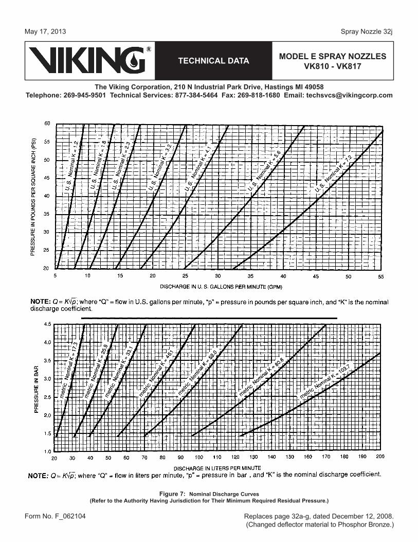
Figure 7: nominal discharge Curves (refer to the authority Having Jurisdiction for Their minimum required residual pressure.)
Form No. F_062104 Replaces page 32a-g, dated December 12, 2008. (Changed deflector material to Phosphor Bronze.)