technical cable guide - prysmian new zealand limited · welcome to the latest edition of the...
TRANSCRIPT

One stop-shopfor all yourcable needs
Technical cable guideJune 2015
New Zealand edition

Welcome to the latest edition of the Technical Cable Guide.
Following the recent acquisition of Draka, the Prysmian Group is now the world’s largest producer of power and telecommunication cables with 97 manufacturing plants, 17 Research & Development Centres, and around 22,000 employees.
A global solutions provider, Prysmian offers a wide range of integrated solutions, such as cable systems, system design and engineering, project management, installation and postsale services.
Prysmian focuses on continuous product innovation and on achieving a competitive edge by focusing on research and development. This is done through Prysmian’s own research & development centres and by co-operating with universities, scientific institutions and our valued customers. Prysmian’s world-wide organisation makes and delivers advanced technological solutions to customers anywhere in the world.
Prysmian is committed to providing all of the necessary technical, installation, safety and practical information that may be required by designers, installers and users of our products in a comprehensive hand book that can easily be used in the field.
Please accept this latest edition of the Technical Cable Guide with our compliments.
Prysmian Cables & Systems Australia Pty Ltd proudly manufactures in Australia and operates certified management systems compliant with the requirements of;
ISO 9001:2000 Quality Management Systems AS/NZS 4801:2001 Occupational Health & Safety Management SystemsOHSAS 18001:1999 Assessment Specification for Occupational Health & Safety Management SystemsISO 14001:2004 Environmental Management Systems
Prysmian New Zealand Limited proudly manufactures in New Zealand and operates certified management systems compliant with the requirements of;
ISO 9001:2000Quality Management Systems
AS/NZS 4801:2001 Occupational Health & Safety Management Systems
OHSAS 18001:1999Assessment Specification for OccupationalHealth & Safety Management Systems
ISO 14001:2004Environmental Management Systems
WARNING
Cables must be installed according to the requirements of AS/NZS 3000, the Wiring Rules and any supplementary requirements of appropriate local Electricity Authorities, by an Electrician who holds a valid licence, appropriate to the State, Territory or Country where installation is to take place.
The Wiring Rules are applied throughout Australia by means of State and Territory Acts and Regulations. In general these Acts and Regulations specify compliance with the Rules, however, because of local requirements, some variation to specific clauses may be called for by means of these Acts and Regulations.
Note: Current ratings data contained in the cable selection category of this guide are based on Australian/New Zealand Standards (AS/NZS 3008.1.1).
1300 300 304 | WWW.PRYSMIAN.COM.AU 105
GENERAL INFORMATION
Solid conductor: A conductor consisting of a single wire.
TACW: Tinned annealed copper wire.
TCu: Tinned copper conductor.
Thermoplastic material: A material that can be readily softened and resoftened by repeated heating, eg., PVC and PE.
Thermosetting material: A material which cures by chemical reaction when heated and, when cured, cannot be resoftened by heating, eg., XLPE.
Tinsel conductor: A conductor comprising fine flattened copper wires assembled in combination with textile material to achieve a high degree of flexibility.
TPS: Thermoplastic sheath. (See Thermoplastic material).
XLPE: Cross linked polyethylene. For LV application, usually refers to X-90 grade. (See Thermosetting material).
ACMA Approval tick. RCM Approval tick.
Whilst every care has been taken in the preparation of this publication, Prysmian takes no responsibility for any errors and or omissions. This booklet is intended as a guide only and reference must be made by any person using this booklet to the appropriate Australian/NZ Standard and or to local electricity supply authority rulings.
The company reserves the right to make changes in product without notice.
The Prysmian Guide to Cable has been completely revised and makes reference to the most recent information available. Information herein refers to common low voltage power and communication cables used by industry. For information not covered in this publication eg. High Voltage XLPE and EPR, Fibre Optics and other specialised Power and Communication cables please contact your nearest Prysmian Sales Office on 1300 300 304.
Printed in Australia.
Copyright © Prysmian Cables & Systems (ABN 36 096 594 080) 2012.
All rights reserved. Subject to change without notice.
Quality ISO 9001
DISCLAIMER
Cables must be installed according to the requirements of AS/NZS 3000, the Wiring Rules and any supplementary requirements of appropriate local Electricity Authorities, by an Electrician who holds a valid licence, appropriate to the State, Territory or Country where installation is to take place.
The Wiring Rules are applied through- out Australia by means of State and Territory Acts and Regulations.
In general these Acts and Regulations specify compliance with the Rules, however, because of local requirements, some variation to specific clauses may be called for by means of these Acts and Regulations.
Note: Current ratings data contained in the cable selection category of this guide are based on Australian/New Zealand Standards (AS/NZSS 3008.1.2.).
Welcome to the latest edition of the Technical Cable Guide.
Following the recent acquisition of Draka, the Prysmian Group is now the world’s largest producer of power and telecommunication cables with 97 manufacturing plants, 17 Research & Development Centres, and around 22,000 employees.
A global solutions provider, Prysmian offers a wide range of integrated solutions, such as cable systems, system design and engineering, project management, installation and postsale services.
Prysmian focuses on continuous product innovation and on achieving a competitive edge by focusing on research and development. This is done through Prysmian’s own research & development centres and by co-operating with universities, scientific institutions and our valued customers. Prysmian’s world-wide organisation makes and delivers advanced technological solutions to customers anywhere in the world.
Prysmian is committed to providing all of the necessary technical, installation, safety and practical information that may be required by designers, installers and users of our products in a comprehensive hand book that can easily be used in the field.
Please accept this latest edition of the Technical Cable Guide with our compliments.
Prysmian Cables & Systems Australia Pty Ltd proudly manufactures in Australia and operates certified management systems compliant with the requirements of;
ISO 9001:2000 Quality Management Systems AS/NZS 4801:2001 Occupational Health & Safety Management SystemsOHSAS 18001:1999 Assessment Specification for Occupational Health & Safety Management SystemsISO 14001:2004 Environmental Management Systems

You might ask yourself why you should choose cables from us, and not from somewhere else? It’s a fair question. There are many very good reasons.
First of all we’re New Zealanders. We’ve been producing tailor-made cables here since 1946. We know what it takes to deal with the many different challenges that tough New Zealand conditions require.
Second of all we combine this local knowledge with the strength of being a global market leader. Being the world’s largest producer of power and telecom-munication cables means we have the muscles to innovate and customise our solutions to perfectly match your needs. At our disposal we have 91 manufactur-ing plants, 17 research and development centres and around 19 000 employees.
In addition we co-operate with universities, scientific institutions and, perhaps most importantly, with you. Your satisfaction is our livelihood. Based on your needs and your feedback we constantly improve to make sure our offer fits the bill.
No matter what kind of cable you need, we have it. And if not, we’ll invent it. And it doesn’t end there. In our offer you’ll find the best technical support on the market – before, during and after.
That’s why doing business with us pays off.
Please accept this latest edition of the Technical Cable Guide with our compliments.
Why do business with Prysmian?Because it pays off.

2 WWW.PRYSMIANCABLE.CO.NZ ∣ 0800 492 225
No worries. Regardless of what cables you’re looking for, we have them for sure. A full market offer ranging from construction, power and telecom cables. And if not, we’ll invent them. Plus, we provide you with all the services you might need – before, during and after.
One stop shop.We have all the cables you need.

0800 492 225 ∣ WWW.PRYSMIANCABLE.CO.NZ 3
PVC Cables 450/750V 8Single Core PVC/PVC SDI2 & 3 Core PVC/PVC Flat2 & 3 Core + Earth PVC/PVC Flat2, 3 & 4 Core + Earth PVC/PVC Orange Circular
PVC Cables 0.6/1kV 10Single Core PVC Insulated Building Wire2 & 3 Core plus Earth PVC/PVC Orange Circular4 Core plus Earth PVC/PVC Orange Circular2 & 3 Core plus Earth PVC/SWA/PVC Orange Circular4 Core plus Earth PVC/SWA/PVC Orange CircularSolar Cable
XLPE Cables 0.6/1kV 17Single Core Flexible XLPE/PVC Copper SDI - X-90Single Core Flexible XLPE/PVC Copper SDI - RE-110Single Core XLPE/PVC Copper SDISingle Core XLPE/PVC Aluminium SDI2 & 3 Core plus Earth XLPE/PVC Circular4 Core & 4 Core plus Earth XLPE/PVC Circular3 Core plus Earth XLPE/SWA/PVC Circular4 Core plus Earth XLPE/SWA/PVC Circular
Instrumentation Cables 23P50 - Overall Screen (CS)P50 - Element And Overall Screen (ESCS)P51 - Overall Screen (CS)P53 - Overall Screen (CS)P53 - Element And Overall Screen (ESCS)P55 - Overall Screen (CS)P55 - Element And Overall Screen (ESCS)P56 - Overall (Cs) Or Element And Overall Screen (ESCS)P31 Data - Electrical Characteristics
Control Cables 0.6/1kV 271.5mm2 Multicore plus Earth PVC/PVC Control2.5mm2 Multicore plus Earth PVC/PVC Control1.5mm2 Multicore plus Earth PVC/SWA/PVC Control2.5mm2 Multicore plus Earth PVC/SWA/PVC Control
Power Cables
No worries. Regardless of what cables you’re looking for, we have them for sure. A full market offer ranging from construction, power and telecom cables. And if not, we’ll invent them. Plus, we provide you with all the services you might need – before, during and after.
One stop shop.We have all the cables you need.
Contents

4 WWW.PRYSMIANCABLE.CO.NZ ∣ 0800 492 225
Aerial Cables 0.6/1kV 29Single Core PVC Insulated Aerial2 Core Parallel Webbed PVC Insulated Aerial2, 3 & 4 Core Twisted PVC Insulated Aerial
Firestop Cables 0.6/1kV 31Single Core Flexible FS110Multicore FS902 Core Flat FS90Single Core FS110Multicore FS110
Vastec EMC/Variable Speed Drive Cables 0.6/1kV 35Flexible XLPE/PVC ScreenedRigid XLPE/PVC Screened
Other Special Cables 36
Power CablesContinued
Communication Cables 38
Cable Selection 40
Communication Cables
Cable Selection
Contents

0800 492 225 ∣ WWW.PRYSMIANCABLE.CO.NZ 5
Current Ratings 46Two Single Core Cables 75°CTwo Single Core Cables 90°CTwo Single Core Cables, Aluminium 90°CTwo Single Core Cables 110°CThree Single Core Cables 75°CThree Single Core Cables 90°CThree Single Core Cables, Aluminium 90°CThree Single Core Cables 110°CTwo Core Cables 75°CTwo Core Cables 90°CTwo Core Cables 110°CThree & Four Core Cables 75°CThree & Four Core Cables 90°CThree & Four Core Cables 110°CPVC - Aerial CableFlexible CordsPVC - Flexible 90°CPVC - Flexible 110°CPVC - Flexible 75°CFlextreme Elastometric Flex - Flexible 90°CDerating FactorsRating Factors
Effective Cross Sectional Areas of PVC Cables 70
Current CarryingCapacities &Voltage Drops
Cable In Conduit
3 Phase Formulae 72Motor Current Table Single PhaseMotor Current Table Three PhaseShort Circuit CapacityConductor Stranding, Resistance & DiameterWire Gauges SWG/Metric/AWGAmerican ConductorsImperial ConductorsMinimum Copper Earthing Conductor SizeCable InstallationRecommended Minimum Bending RadiiMaximum Pulling TensionsSafe Working Force - FlexInsulation & Sheath PropertiesGlossary of Terms
General Information
Contents

6 WWW.PRYSMIANCABLE.CO.NZ ∣ 0800 492 225
We’ve been producing tailor-made cables for New Zealand in New Zealand since 1946. And we will continue to do so. Our great staff of highly skilled and experienced people know what it takes to make cables that withstand everything from geothermal heat to crazy keas. Simply primo cables.
No need to go overseas.We are here to serve you.

0800 492 225 ∣ WWW.PRYSMIANCABLE.CO.NZ 7
Power Cables

8 WWW.PRYSMIANCABLE.CO.NZ ∣ 0800 492 22510 WWW.PRYSMIAN.COM.AU | 1300 300 304
PVC Cables
PVC SDI 450/750V
Cable description: Single Core Cable, Copper Conductor, V-90 PVC Insulated and 3V-90 PVC Sheathed, to AS/NZS 5000.2.
*Single Wire Conductor.
For conductors 25mm2 and above please refer to XLPE/PVC product pages.
Catalogue ReferenceNominal
Conductor Areamm2
Approx. Overall Diameter
mm
Approx. Masskg/100m
Min. Installed Bending Radius
mm
*1.0SSDI 1.0 4.1 2.9 15
1.5SDI 1.5 4.5 3.5 20
2.5SDI 2.5 5.2 5.1 20
4SDI 4.0 6.2 7.4 25
6SDI 6.0 6.8 9.8 25
10SDI 10 8.2 15 35
16SDI 16 9.4 22 40
PVC FLAT 450/750V
Cable description: 2 & 3 Core Flat TPS Cable, Copper Conductor V-90, PVC Insulated and 3V-90 PVC Sheathed, to AS/NZS 5000.2.
*Single Wire Conductors.
2C = 2 Core. 3C = 3 Core.
Catalogue Reference Nominal Conductor Area
mm2
Approx. Overall Dimensions
mm
Approx. Masskg/100m
Min. Installed Bending Radius
mm
2C 3C 2C 3C 2C 3C 2C 3C
*1.0ST *1.0S3CF 1.0 6.6 x 4.3 9.0 x 4.3 5.2 7.3 15 20
1.5T 1.53CF 1.5 7.3 x 4.6 10.1 x 4.6 6.4 9.0 20 20
2.5T 2.53CF 2.5 8.9 x 5.5 12.4 x 5.5 9.9 15 20 20
4T 4.0 10.7 x 6.5 15 25
6T 6.0 11.9 x 7.1 20 30
10T 10 15.0 x 8.8 31 35
16T 16 17.3 x 10.0 45 40
CERTIFIED
Green Star
GREEN STARCERTIFIED
◊ The cables listed above are available in Green Star approved PVC or made to order Non PVC Low Smoke Zero Halogen.

0800 492 225 ∣ WWW.PRYSMIANCABLE.CO.NZ 91300 300 304 | WWW.PRYSMIAN.COM.AU 11
POWER CABLES
PVC FLAT 450/750V
Cable description: 2 & 3 Core plus Earth Flat TPS Cable, Copper Conductor, V-90 PVC Insulated and 3V-90 PVC Sheathed, to AS/NZS 5000.2.
PVC MULTICORE CIRCULAR 450/750V
Cable description: 2, 3 & 4 Core plus Earth Circular Cable, Copper Conductor, V-90 PVC Insulated and 5V-90 PVC Sheathed, to AS/NZS 5000.2.
*Single Wire Conductor.
2C+E = 2 Core + Earth. 3C+E = 3 Core + Earth.
2C+E = 2 Core + Earth. 3C+E = 3 Core + Earth. 4C+E = 4 Core + Earth.
For conductors less than 10mm2 please refer to Cables to AS/NZS 5000.2.
Catalogue Reference Nominal Conductor Area
mm2
Approx. Overall Dimensions
mm
Approx. Masskg/100m
Min. Installed Bending Radius
mm
2C+E 3C+E 2C+E 3C+E 2C+E 3C+E 2C+E 3C+E
*1.0STE *1.0S3CEF 1.0 9.3 x 4.6 11.7 x 4.6 8 10 20 20
1.5TE 1.53CEF 1.5 10.1 x 4.6 12.8 x 4.6 9 12 20 20
2.5TE 2.53CEF 2.5 12.4 x 5.5 15.8 x 5.5 15 19 20 20
4TE 43CEF 4.0 14.1 x 6.5 18.3 x 6.5 19 26 25 25
6TE 63CEF 6.0 15.3 x 7.1 20.1 x 7.1 24 33 30 30
10TE 103CEF 10 19.2 x 8.8 25.8 x 8.8 38 52 35 35
16TE 163CEF 16 22.5 x 10.0 29.7 x 10.0 54 75 40 40
Catalogue ReferenceNominal
Conductor Areamm2
Approx. Overall Diameter
mm
Approx. Masskg/100m
Min. Installed Bending Radius
mm
2C+E 3C+E 4C+E 2C+E 3C+E 4C+E 2C+E 3C+E 4C+E 2C+E 3C+E 4C+E
1.52CEOC 1.53CEOC 1.54CEOC 1.5 8.3 9.0 10.0 11 13 16 35 40 40
2.52CEOC 2.53CEOC 2.54CEOC 2.5 10.0 10.9 11.9 17 20 24 40 45 50
42CEOC 43CEOC 44CEOC 4.0 11.2 12.3 13.7 22 27 34 45 50 55
62CEOC 63CEOC 64CEOC 6.0 12.2 13.6 15.1 27 35 44 50 55 60
102CEOC 103CEOC 104CEOC 10 15.7 17.5 19.4 40 53 65 65 70 80
162CEOC 163CEOC 164CEOC 16 18.0 19.8 22.2 57 75 94 75 80 90
CERTIFIED
Green Star
GREEN STARCERTIFIED
◊ The cables listed above are available in Green Star approved PVC or made to order Non PVC Low Smoke Zero Halogen.

10 WWW.PRYSMIANCABLE.CO.NZ ∣ 0800 492 225
PVC INSULATED 0.6/1KVCable description: Single Core Cable, Copper Conductor, V-90 PVC Insulated, Unsheathed, to AS/NZS 5000.1.
*Single Wire Conductor.
Catalogue ReferenceNominal
Conductor Areamm2
Approx. Overall Diameter
mm
Approx. Masskg/100m
Min. Installed Bending Radius
mm
*1.OSBW 1.0 2.8 1.7 10
1.5BW 1.5 3.2 2.2 15
2.5BW 2.5 3.7 3.3 15
4BW 4.0 4.6 5.3 20
6BW 6.0 5.2 7.4 20
10BW 10 6.2 12 25
16BW 16 7.3 18 30
25BW 25 8.9 28 35
35BW 35 10.1 37 40
50BW 50 11.9 50 50
70BW 70 13.5 69 55
95BW 95 15.9 96 65
120BW 120 17.3 119 70
150BW 150 19.5 146 80
185BW 185 21.7 184 85
PVC COPPER SDI 0.6/1KVCable description: Single Core Cable, Class 2 Conductor, Copper Conductor, V-90 PVC Insulated, 5V-90 PVC Sheathed, to AS/NZS 5000.1.Note: Outersheath colour available: RED, WHITE, BLUE, BLACK except *1. *1, Orange insulation/Orange sheath
Catalogue ReferenceNominal
Conductor Areamm2
Approx. Overall Diameter
mm
Approx. Masskg/100m
Min. Installed Bending Radius
mm
4CUPVC*1 4 7.4 10.3 30
16CUPVC 16 10 24.4 40
25CUPVC 25 11.7 36.4 47
35CUPVC 35 12.9 47.2 77
70CUPVC 70 16.5 82.4 99
◊ The cables listed above are available in Green Star approved PVC or made to order Non PVC Low Smoke Zero Halogen.
POWER CABLES

0800 492 225 ∣ WWW.PRYSMIANCABLE.CO.NZ 11
PVC ALUMINIUM SDI 0.6/1KVCable description: Single Core Cable, All Aluminium Conductor, V-90 PVC Insulated, 5V-90 PVC Sheathed, to AS/NZS 5000.1.Note: Outersheath colour available: RED, WHITE, BLUE, BLACK
Catalogue ReferenceNominal
Conductor Areamm2
Approx. Overall Diameter
mm
Approx. Masskg/100m
Min. Installed Bending Radius
mm
25ALPVC [NAMU] 24.5 11.6 20 46
50ALPVC [KUTU] 49.5 14.8 33 89
105ALPVC [BEETLE] 106 19.7 56 118
185ALPVC [HUHU] 185 25.2 94 151
PVC MULTICORE CIRCULAR 0.6/1KVCable description: 2 & 3 Core plus Earth Circular Cable, Copper Conductor, V-90 PVC Insulated and 5V-90 PVC Sheathed, to AS/NZS 5000.1.
2C+E = 2 Core + Earth. 3C+E = 3 Core + Earth.For conductors less than 10mm2 please refer to Cables to AS/NZS 5000.2.
Catalogue Reference Nominal Conductor Area
mm2
Approx. Overall Diameter
mm
Approx. Masskg/100m
Min. Installed Bending Radius
mm
2C+E 3C+E 2C+E 3C+E 2C+E 3C+E 2C+E 3C+E
1.52CEOC1KV 1.53CEOC1KV 1.5 10.1 11.0 15 18 40 45
2.52CEOC1KV 2.53CEOC1KV 2.5 11.3 12.3 20 24 45 50
42CEOC1KV 43CEOC1KV 4.0 12.9 14.0 26 32 50 55
62CEOC1KV 63CEOC1KV 6.0 14.0 15.2 33 41 55 60
102CEOC1KV 103CEOC1KV 10 16.5 18.1 43 56 65 70
162CEOC1KV 163CEOC1KV 16 18.6 20.4 59 78 75 80
◊ The cables listed above are available in Green Star approved PVC or made to order Non PVC Low Smoke Zero Halogen.
POWER CABLES
PVC MULTICORE CIRCULAR 0.6/1KVCable description: 4 Core plus Earth Circular Cable, Copper Conductor, V-90 PVC Insulated and 5V-90 PVC Sheathed, to AS/NZS 5000.1.
Catalogue ReferenceNominal
Conductor Areamm2
Approx. Overall Diameter
mm
Approx. Masskg/100m
Min. Installed Bending Radius
mm
1.54CEOC1KV 1.5 11.9 21 50
2.54CEOC1KV 2.5 13.3 29 55
44CEOC1KV 4.0 15.4 39 60
64CEOC1KV 6.0 16.8 50 70
104CEOC1KV 10 20.0 69 80
164CEOC1KV 16 22.6 92 90

12 WWW.PRYSMIANCABLE.CO.NZ ∣ 0800 492 225
PVC MULTICORE SWA CIRCULAR 0.6/1KVCable description: 4 Core plus Insulated Earth Circular Cable, Copper Conductor, V-90 PVC Insulated and PVC Bedded, Steel Wire Armoured, 5V-90PVC Sheathed, to AS/NZS 5000.1.
Catalogue ReferenceNominal
Conductor Areamm2
Approx. Diameter Over Bedding
mm
Approx. Overall Diameter
mm
Approx. Masskg/100m
Min. Installed Bending Radius
mm
1.54CEOCA1KV 1.5 10.9 17.0 59 205
2.54CEOCA1KV 2.5 12.3 18.5 71 225
44CEOCA1KV 4.0 14.4 20.5 87 245
64CEOCA1KV 6.0 15.8 21.9 102 265
104CEOCA1KV 10 19.0 25.8 145 310
164CEOCA1KV 16 21.6 28.4 184 340
◊ The cables listed above are available in Green Star approved PVC or made to order Non PVC Low Smoke Zero Halogen.
POWER CABLES
PVC MULTICORE SWA CIRCULAR 0.6/1KVCable description: 2 & 3 Core plus Earth Circular Cable, Copper Conductor, V-90 PVC Insulated and PVC Bedded, Steel Wire Armoured, 5V-90 PVCSheathed, to AS/NZS 5000.1.
2C+E = 2 Core + Earth. 3C+E = 3 Core + Earth.
Catalogue ReferenceNominal
Conductor Areamm2
Max. Diameter Under Armour
mm
Approx. Overall Diameter
mm
Approx. Masskg/100m
Min. Installed Bending Radius
mm
2C+E 3C+E 2C+E 3C+E 2C+E 3C+E 2C+E 3C+E 2C+E 3C+E
1.52CEOCA1KV 1.53CEOCA1KV 1.5 9.1 10.0 15.2 16.1 47 52 185 195
2.52CEOCA1KV 2.53CEOCA1KV 2.5 10.3 11.3 16.9 17.4 56 63 195 210
42CEOCA1KV 43CEOCA1KV 4.0 11.8 13.0 17.9 19.2 67 77 215 230
62CEOCA1KV 63CEOCA1KV 6.0 13.0 14.2 19.1 20.3 77 88 230 245
102CEOCA1KV 103CEOCA1KV 10 15.5 17.1 21.6 23.2 94 111 260 280
162CEOCA1KV 163CEOCA1KV 16 17.6 19.4 23.7 26.2 117 156 285 315
◊ The cables listed above are available in Green Star approved PVC or made to order Non PVC Low Smoke Zero Halogen.

Doing business with us should be like having the pie and eating it. And the best way to get there is to listen to you. Based on your feedback we constantly improve. Increased stock availability, quicker quote responses, improved labelling and reliable deliveries are just some examples that’ll simplify your daily life. Care for another slice?
It’s that easy.Doing business the Prysmian way.

14 WWW.PRYSMIANCABLE.CO.NZ ∣ 0800 492 225
POWER CABLES
Technical data:
Cable description: Single core class 5 conductor designed in accordance with IEC 60228 (VDE 0295).
SOLAR CABLES
SINGLE CORE SOLAR CABLES
Fire behaviour
Fire performance IEC 60332-1
Smoke density IEC 61034, EN 50268-2
Halogen Acid Gas Emission IEC 670754-1, EN 50267-2-1
Electrical parameters
Rated voltage (Uo/U) 600/1000V AC
Test voltage 6500 V AC/15000 V/5 min
Thermal parameters
Ambient temperature -40°C up to +90°C
Maximum permissable conductor operating temperature +120°C
ItemSpecifications
4 mm2 6 mm2
Product code 5749083 5749090
Cross-section area (mm2) 4 mm2 6 mm2
Material Stranded tinned copper
Conductor diameter 2.4 5.7
Insulation material HEPR 120°C similar to IEC 60502-1
Sheath material XLEVA rubber 120°C
Overall diameter of cable 5.2 5.7
Approx. net weight 58 76
Minimum bending radius ≥ 4 x cable OD
Sheath colours Black, blue, red

0800 492 225 ∣ WWW.PRYSMIANCABLE.CO.NZ 15
POWER CABLES
Cable description: Dual core class 5 conductor.
TWIN SOLAR CABLES
ItemSpecifications
4 mm2 6 mm2
Product code 5749045 5749069
Conductor
Cross-section area (mm2) 2 x 4 mm2 2 x 6 mm2
Material Stranded tinned copper
Size (mm) 2 x (56/0.30 ± 0.008) 2 x (84/(0.30 ± 0.008))
Size OD (mm) 2.59 ± 0. 3.12 ± 0.05 01 3.12 ± 0.05
Insulation
Material Electron-beam cross-linked materials
Nominal OD (mm) 4.45 ± 0.15 4.80 ± 0.15
Colour One red, one black
Sheath
Material Electron-beam cross-linked materials
Nominal OD (mm) 5.80 ± 0.10 x 12.00 ± 0.20 6.45 ± 0.25 x 13.40 ± 0.35
Colour Black
Resistance values
Conductor resistance ≤ 5.09Ω/km at 20°C ≤ 3.39Ω/km at 20°C
Insulation resistance ≤ 1014Ω/km at 20°C
UV resistance > 720 hours

16 WWW.PRYSMIANCABLE.CO.NZ ∣ 0800 492 225
With our improved range of flexible cables we’ve brought flexibility to a completely new level. From now on it’ll be a lot easier to get into those tight corners with less equipment, less people and in half the time. With a 50% decrease in installation time, imagine what you could do with those savings ...
Flexitime!Our flexible cables save you time and money.

0800 492 225 ∣ WWW.PRYSMIANCABLE.CO.NZ 171300 300 304 | WWW.PRYSMIAN.COM.AU 15
XLPE Cables
FLEXIBLE XLPE COPPER SDI 0.6/1KV
Cable description: Flexible Single Core Cable, Class 5 Conductor, 5V-90 X-90 XLPE Insulated, PVC Sheathed, to AS/NZS 5000.1.
Note: For fixed installation.
Product Code
Conductor CableMin.
InstalledBendingRadius
mm
Nominal C.S.A.mm2
Nominal Diameter
mm
NominalInsulationThickness
mm
Overall Diameter Approx.Mass
kg/100mMinimummm
Maximummm
351CFF90 35 7.7 0.9 11.9 12.7 38.7 76
501CFF90 50 9.3 1.0 13.7 14.5 53.5 87
701CFF90 70 11.1 1.0 15.7 16.5 72.9 99
951CFF90 95 12.8 1.0 17.5 18.4 94.2 110
1201CFF90 120 14.5 1.2 19.4 20.3 118.6 122
1501CFF90 150 16.3 1.4 21.7 22.7 147.4 136
1851CFF90 185 18.0 1.6 23.8 24.8 178.0 149
2401CFF90 240 20.8 1.7 26.9 28.0 231.8 168
3001CFF90 300 23.4 1.8 29.8 30.9 288.3 186
4001CFF90 400 26.8 2.0 33.8 35.0 376.2 210
5001CFF90 500 30.3 2.2 37.8 39.1 474.5 235
6301CFF90 630 35.1 2.4 43.2 44.6 628.9 268
CERTIFIED
Green Star
GREEN STARCERTIFIED

18 WWW.PRYSMIANCABLE.CO.NZ ∣ 0800 492 22516 WWW.PRYSMIAN.COM.AU | 1300 300 304
POWER CABLES
XLPE COPPER SDI 0.6/1KV
Cable description: Single Core Cable, Class 2 Conductor, Copper Conductor, X-90 XLPE Insulated, 5V-90 PVC Sheathed, to AS/NZS 5000.1.
Note: Non Compacted Conductor except otherwise stated.
Catalogue ReferenceNominal
Conductor Areamm2
Approx. Overall Diameter
mm
Approx. Masskg/100m
Min. Installed Bending Radius
mm
16CUXLP 16 9.5 21 40
25CUXLP 25 11.2 31 45
35CUXLP 35 12.4 41 50
50CUXLP 50 13.9 54 55
70CUXLP 70 15.8 73 65
95CUXLP 95 17.9 100 75
120CUXLP 120 19.6 124 80
150CUXLP 150 21.9 153 90
185CUXLP 185 24.1 190 100
240CUXLP 240 27.1 246 165
300CUXLP 300 30.0 307 180
400CUXLP 400 33.5 388 200
*500CCUXLP *500 35.2 489 280
*630CCUXLP *630 39.7 625 315
* Compacted Conductor.
Note: LSOH version available.
FLEXIBLE XLPE COPPER SDI 0.6/1KV
Cable description: Flexible Single Core Cable, Class 5 Conductor, RE-110 Insulated, HFS-110-TP Sheathed, LSOH, to AS/NZS 5000.1.
Note: For fixed installation.
Product Code
Conductor CableMin.
InstalledBendingRadius
mm
Nominal C.S.A.mm2
Nominal Diameter
mm
NominalInsulationThickness
mm
Overall Diameter Approx.Mass
kg/100mMinimummm
Maximummm
351CFF110 35 7.7 1.2 12.5 13.3 40.3 80
501CFF110 50 9.3 1.4 14.5 15.3 55.9 92
701CFF110 70 11.1 1.4 16.4 17.2 75.0 103
951CFF110 95 12.8 1.6 18.6 19.4 97.9 116
1201CFF110 120 14.5 1.6 20.2 21.1 122.0 127
1501CFF110 150 16.3 1.8 22.6 23.6 151.1 141
1851CFF110 185 18.0 2.0 24.8 25.8 183.1 155
2401CFF110 240 20.8 2.2 28.2 29.3 239.0 176
3001CFF110 300 23.4 2.4 29.9 31.1 290.0 186
4001CFF110 400 26.8 2.6 35.2 36.5 386.2 219
5001CFF110 500 30.3 2.8 39.3 40.6 485.7 244
6301CFF110 630 35.1 2.8 44.1 45.6 637.3 273
CERTIFIED
Green Star
GREEN STARCERTIFIED

0800 492 225 ∣ WWW.PRYSMIANCABLE.CO.NZ 191300 300 304 | WWW.PRYSMIAN.COM.AU 17
POWER CABLES
XLPE ALUMINIUM SDI 0.6/1KV
Cable description: Single Core Cable, Aluminium Conductor, X-90 XLPE Insulated, 5V-90 PVC Sheathed, to AS/NZS 5000.1.
Note: Class 2 Compacted Conductor.
Catalogue ReferenceNominal
Conductor Areamm2
Approx. Overall Diameter
mm
Approx. Masskg/100m
Min. Installed Bending Radius
mm
25CALXLP 25 10.9 15 85
35CALXLP 35 11.9 18 95
50CALXLP 50 13.1 23 105
70CALXLP 70 15.0 31 120
95CALXLP 95 16.9 40 135
120CALXLP 120 18.5 48 145
150CALXLP 150 20.4 58 165
185CALXLP 185 22.6 73 180
240CALXLP 240 25.3 93 200
300CALXLP 300 28.0 114 225
400CALXLP 400 31.5 145 250
500CALXLP 500 35.2 180 280
630CALXLP 630 39.6 230 315
CERTIFIED
Green Star
GREEN STARCERTIFIED
Note: LSOH version available.
XLPE ALUMINIUM SDI 0.6/1KVCable description: Single Core Cable, Aluminium Conductor, X-90 XLPE Insulated, 5V-90 PVC Sheathed, to AS/NZS 5000.1.Note: Non Compacted Conductor except otherwise specified. *Compacted Conductor
Catalogue ReferenceNominal
Conductor Areamm2
Approx. Overall Diameter
mm
Approx. Masskg/100m
Min. Installed Bending Radius
mm
25CALXLP* 25 10.9 15 85
35CALXLP* 35 11.9 18 95
50CALXLP* 50 13.1 23 105
70ALXLP 70 15.9 34 95
95ALXLP 95 18.0 45 108
120ALXLP 120 19.8 54 118
150ALXLP 150 21.9 67 131
185ALXLP 185 24.2 80 145
240ALXLP 240 27.2 103 163
300ALXLP 300 30.0 126 180
400ALXLP 400 33.6 159 201
500ALXLP 500 37.4 196 224
630ALXLP 630 42.3 252 254
Note: LSOH version available.

20 WWW.PRYSMIANCABLE.CO.NZ ∣ 0800 492 22518 WWW.PRYSMIAN.COM.AU | 1300 300 304
POWER CABLES
XLPE MULTICORE CIRCULAR 0.6/1KV
Cable description: 2 & 3 Core plus Earth Circular Cable, Copper Conductor, X-90 XLPE Insulated, 5V-90 PVC Sheathed, to AS/NZS 5000.1.
Note: Non Compacted Conductor.
2C+E = 2 Core + Earth. 3C+E = 3 Core + Earth.
Catalogue Reference Nominal Conductor Area
mm2
Approx. Overall Diameter
mm
Approx. Masskg/100m
Min. Installed Bending Radius
mm
2C+E 3C+E 2C+E 3C+E 2C+E 3C+E 2C+E 3C+E
1.52CEXLP 1.5 10.1 14 41
2.52CEXLP 2.5 11.3 19 46
42CEXLP 4.0 12.2 23 49
62CEXLP 6.0 13.2 29 53
102CEXLP 10 15.1 41 61
162CEXLP 16 17.4 54 70
252CEXLP 25 21.0 75.4 85
253CEXLP 25 22.4 102 90
353CEXLP 35 25.0 136 150
503CEXLP 50 28.5 183 170
703CEXLP 70 33.0 254 200
953CEXLP 95 37.0 336 220
1203CEXLP 120 41.0 422 245
1503CEXLP 150 46.0 525 275
1853CEXLP 185 51.6 665 310
2403CEXLP 240 58.1 868 350
3003CEXLP 300 64.4 1084 385
CERTIFIED
Green Star
GREEN STARCERTIFIED
Note: LSOH version available.
18 WWW.PRYSMIAN.COM.AU | 1300 300 304
POWER CABLES
XLPE MULTICORE CIRCULAR 0.6/1KV
Cable description: 2 & 3 Core plus Earth Circular Cable, Copper Conductor, X-90 XLPE Insulated, 5V-90 PVC Sheathed, to AS/NZS 5000.1.
Note: Non Compacted Conductor.
2C+E = 2 Core + Earth. 3C+E = 3 Core + Earth.
Catalogue Reference Nominal Conductor Area
mm2
Approx. Overall Diameter
mm
Approx. Masskg/100m
Min. Installed Bending Radius
mm
2C+E 3C+E 2C+E 3C+E 2C+E 3C+E 2C+E 3C+E
1.52CEXLP 1.5 10.1 14 41
2.52CEXLP 2.5 11.3 19 46
42CEXLP 4.0 12.2 23 49
62CEXLP 6.0 13.2 29 53
102CEXLP 10 15.1 41 61
162CEXLP 16 17.4 54 70
252CEXLP 25 21.0 75.4 85
253CEXLP 25 22.4 102 90
353CEXLP 35 25.0 136 150
503CEXLP 50 28.5 183 170
703CEXLP 70 33.0 254 200
953CEXLP 95 37.0 336 220
1203CEXLP 120 41.0 422 245
1503CEXLP 150 46.0 525 275
1853CEXLP 185 51.6 665 310
2403CEXLP 240 58.1 868 350
3003CEXLP 300 64.4 1084 385
CERTIFIED
Green Star
GREEN STARCERTIFIED
Note: LSOH version available.

0800 492 225 ∣ WWW.PRYSMIANCABLE.CO.NZ 211300 300 304 | WWW.PRYSMIAN.COM.AU 19
POWER CABLES
XLPE MULTICORE CIRCULAR 0.6/1KV
Cable description: 4 Core & 4 Core plus Earth Circular Cable, Copper Conductor, X-90 XLPE Insulated, 5V-90 PVC Sheathed, to AS/NZS 5000.1.
Note: Non Compacted Conductor.
Catalogue ReferenceNominal
Conductor Areamm2
Approx. Overall Diameter
mm
Approx. Masskg/100m
Min. Installed Bending Radius
mm
164CEXLP 16 21.0 87.5 85
254CEXLP 25 24.9 130 150
354CEXLP 35 27.8 173 165
504CEXLP 50 32.0 235 190
704CEXLP 70 37.1 325 225
954CEXLP 95 41.8 437 250
1204CEXLP 120 46.2 547 280
1504CEXLP 150 52.0 680 310
1854CEXLP 185 58.3 857 350
2404CEXLP 240 65.8 1122 395
3004CEXLP 300 72.9 1400 440
XLPE MULTICORE SWA CIRCULAR 0.6/1KV
Cable description: 3 Core plus Earth Circular Cable, Copper Conductor, X-90 XLPE Insulated, PVC Bedded, Steel Wire Armoured, 5V-90 PVC Sheathed,
to AS/NZS 5000.1.
Note: Non Compacted Conductor.
Catalogue ReferenceNominal
Conductor Areamm2
Approx. Diameter Over Bedding
mm
Approx. Overall Diameter
mm
Approx. Masskg/100m
Min. Installed Bending Radius
mm
253CEXLPA 25 21.4 28.2 187 340
353CEXLPA 35 24.0 30.8 229 370
503CEXLPA 50 27.5 34.5 291 415
703CEXLPA 70 31.8 40.0 406 480
953CEXLPA 95 35.6 44.0 504 530
1203CEXLPA 120 39.3 47.9 608 575
1503CEXLPA 150 44.4 54.4 783 655
1853CEXLPA 185 49.6 59.8 949 720
2403CEXLPA 240 56.4 67.0 1198 805
3003CEXLPA 300 62.3 73.3 1447 880
CERTIFIED
Green Star
GREEN STARCERTIFIED
Note: LSOH version available.

22 WWW.PRYSMIANCABLE.CO.NZ ∣ 0800 492 22520 WWW.PRYSMIAN.COM.AU | 1300 300 304
POWER CABLES
XLPE MULTICORE SWA CIRCULAR 0.6/1KV
Cable description: 4 Core plus Earth Circular Cable, Copper Conductor, X-90 XLPE Insulated, PVC Bedded, Steel Wire Armoured, 5V-90 PVC Sheathed,
to AS/NZS 5000.1.
Note: Non Compacted Conductor.
Catalogue ReferenceNominal
Conductor Areamm2
Approx. Diameter Over Bedding
mm
Approx. Overall Diameter
mm
Approx. Masskg/100m
Min. Installed Bending Radius
mm
254CEXLPA 25 23.8 30.6 223 370
354CEXLPA 35 26.8 33.8 278 405
504CEXLPA 50 30.8 38.8 379 465
704CEXLPA 70 35.7 44.1 493 530
954CEXLPA 95 40.0 48.6 624 585
1204CEXLPA 120 44.6 54.6 804 655
1504CEXLPA 150 50.0 60.4 970 725
1854CEXLPA 185 56.4 67.0 1184 805
2404CEXLPA 240 63.5 74.5 1487 895
3004CEXLPA 300 70.2 81.6 1804 980
CERTIFIED
Green Star
GREEN STARCERTIFIED
Note: LSOH version available on request.

0800 492 225 ∣ WWW.PRYSMIANCABLE.CO.NZ 231300 300 304 | WWW.PRYSMIAN.COM.AU 21
POWER CABLES
Instrumentation Cables
INFORM@X®
Cable description: P50-P56 cables are intrinsically safe electrically to as 2380.7 & AS 2381.7. Construction design standard according to EN 50288-7.
Instrumentation cables are used in a broad range of operational conditions, they are primarily allocated to control applications where
optimal protection from electrical noise is required. These cables can be used for digital and analogue data transmission at 110V in PLC
and SCADA systems.
Product Code Pairs Nominal O.D Min. Bending Radius Max. Pulling Tension Approx.Mass
Plain SWA Plain SWA Plain SWA Plain SWA
mm mm mm mm N N kg/km kg/km
P5001CS 1 6.8 - 41 - 70 - 55 -
P5002CS 2 10.3 14.4 62 173 140 1390 121 344
P5004CS 4 11.8 16.6 71 200 280 2060 162 516
P5006CS 6 14.0 18.8 84 226 420 2520 196 631
P5008CS 8 14.4 19.3 87 231 560 2950 256 679
P5010CS 10 17.5 23.1 105 277 700 3360 304 972
P5012CS 12 18.0 23.6 108 284 840 4010 344 1031
P5016CS 16 19.9 25.6 120 307 1120 5060 431 1178
P5020CS 20 22.1 27.7 132 332 1400 6180 519 1343
P5024CS 24 25.0 30.6 150 367 1680 6960 634 1544
P5036CS 36 28.5 35.0 171 420 2520 9450 882 2153
P50 Instrumentation - Overall Screen (CS)
Product Code Pairs Nominal O.D Min. Bending Radius Max. Pulling Tension Approx.Mass
Plain SWA Plain SWA Plain SWA Plain SWA
mm mm mm mm N N kg/km kg/km
P5002ESCS 2 11.5 15.6 69 187 140 1550 146 391
P5004ESCS 4 13.3 18.1 80 218 280 2310 200 598
P5006ESCS 6 16.4 21.4 98 256 420 2890 266 772
P5008ESCS 8 16.8 21.7 101 261 560 3390 312 831
P5010ESCS 10 19.7 25.3 118 304 700 4170 384 1129
P5012ESCS 12 20.3 25.9 122 311 840 4980 437 1203
P5016ESCS 16 22.5 28.2 135 338 1120 5900 551 1393
P5020ESCS 20 25.4 31.1 153 373 1400 6860 691 1618
P5024ESCS 24 28.3 34.7 170 417 1680 8000 814 2084
P5036ESCS 36 32.4 39.3 194 471 2520 11160 1141 2626
P50 Instrumentation - Element And Overall Screen (ESCS)

24 WWW.PRYSMIANCABLE.CO.NZ ∣ 0800 492 22522 WWW.PRYSMIAN.COM.AU | 1300 300 304
POWER CABLES
Product Code Pairs Nominal O.D Min. Bending Radius Max. Pulling Tension Approx.Mass
Plain SWA Plain SWA Plain SWA Plain SWA
mm mm mm mm N N kg/km kg/km
P5102ES 1 Pair 8.1 12.4 48 149 210 1390 85 265
P5103ES 1 Triple 8.5 12.9 51 155 315 1480 107 309
P51 Instrumentation - Overall Screen (CS)
Product Code Triples Nominal O.D Min. Bending Radius Max. Pulling Tension Approx.Mass
Plain SWA Plain SWA Plain SWA Plain SWA
mm mm mm mm N N kg/km kg/km
P5304CS 4 13.4 18.2 80 219 420 2520 212 610
P5306CS 6 16.5 21.5 99 258 630 3150 297 803
P5312CS 12 20.1 25.7 121 309 1260 5450 471 1233
P5316CS 16 22.3 28.0 134 335 1680 6570 596 1435
P5336CS 36 32.1 38.9 192 467 3780 13480 1249 2698
P53 Instrumentation - Overall Screen (CS)
Product Code Triples Nominal O.D Min. Bending Radius Max. Pulling Tension Approx.Mass
Plain SWA Plain SWA Plain SWA Plain SWA
mm mm mm mm N N kg/km kg/km
P5304ESCS 4 15.2 19.5 91 234 420 2920 266 680
P5306ESCS 6 18.1 23.7 109 285 630 3940 346 1034
P5308ESCS 8 18.6 24.2 112 291 840 4980 399 1105
P5312ESCS 12 22.6 28.2 135 338 1260 6470 562 1405
P5316ESCS 16 25.5 31.2 153 374 1680 8050 739 1683
P5336ESCS 36 36.2 43.1 217 517 3780 15360 1504 3140
P53 Instrumentation - Element And Overall Screen (ESCS)
Product Code Pairs Nominal O.D Min. Bending Radius Max. Pulling Tension Approx.Mass
Plain SWA Plain SWA Plain SWA Plain SWA
mm mm mm mm N N kg/km kg/km
P5502CS 2 12.4 17.3 75 207 420 1900 193 547
P5504CS 4 14.5 19.3 87 231 840 2700 272 686
P5506CS 6 17.9 23.5 107 282 1260 3430 373 1059
P5508CS 8 18.4 24.0 110 288 1680 4360 436 1141
P5510CS 10 21.6 27.2 130 327 2100 5320 536 1340
P5512CS 12 22.3 27.9 134 335 2520 5950 617 1458
P55 Instrumentation - Overall Screen (CS)

0800 492 225 ∣ WWW.PRYSMIANCABLE.CO.NZ 251300 300 304 | WWW.PRYSMIAN.COM.AU 23
POWER CABLES
Electrical Characteristics - P31 Data
Cable Type Units P50 CS P50 ESCS P51 ES P53 CS P53 ESCS P55 CS P55 ESCS P56 CS
Conductor Size mm 0.5 0.5 1.5 0.5 0.5 1.5 1.5 1.5
Conductor Resistance at 20°C ohms/100m 3.84 3.84 1.36 3.84 3.84 1.36 1.36 1.36
Insulation Resistance at 20°C mohms/km 10 10 10 10 10 10 10 10
Max Continuous Current Rating A 3.2 3.2 12 3.2 3.2 12 12 12
Max D.C. Voltage Withstand kV 3 3 3 3 3 3 3 3
Capacitance of pairs pF/m 250 250 250 - - 250 250 -
Capacitance Unbalanced between pairs
pF/100m 100 100 - - - 100 100 -
L/R Ratio μH/ohms 25 25 40 25 25 40 40 40
Product Code Pairs Nominal O.D Min. Bending Radius Max. Pulling Tension Approx.Mass
Plain SWA Plain SWA Plain SWA Plain SWA
mm mm mm mm N N kg/km kg/km
P5502ESCS 2 13.3 18.1 80 217 420 2140 215 589
P5504ESCS 4 16.7 21.6 100 260 840 3090 331 803
P5506ESCS 6 19.9 25.6 120 307 1260 4200 426 1173
P5508ESCS 8 20.4 26.1 123 313 1680 5360 501 1266
P5510ESCS 10 24.5 30.2 147 362 2100 6180 640 1546
P5512ESCS 12 25.3 31.0 152 372 2520 6960 736 1662
P55 Instrumentation - Element And Overall Screen (ESCS)
Product Code Pairs Nominal O.D Min. Bending Radius Max. Pulling Tension Approx.Mass
Plain SWA Plain SWA Plain SWA Plain SWA
mm mm mm mm N N kg/km kg/km
P5604CS 4 17.1 22.0 102 264 1260 1260 390 868
P5606CS 6 20.4 26.1 122 313 1890 1890 512 1272
P5612CS 12 25.4 31.1 153 373 3780 3780 957 1816
P5604ESCS 4 18.3 24.0 110 288 1260 1260 425 1073
P5606ESCS 6 22.0 27.6 132 332 1890 1890 556 1380
P5612ESCS 12 28.1 34.5 168 414 3780 3780 989 2234
P56 Instrumentation - Overall (Cs) Or Element And Overall Screen (ESCS)

26 WWW.PRYSMIANCABLE.CO.NZ ∣ 0800 492 22524 WWW.PRYSMIAN.COM.AU | 1300 300 304
POWER CABLES
Core: An insulated wire
Pair: Two cores twisted together (white & black)
Triple: Three cores twisted together (red, white and black)
Element: An assembly of cores, either paired or tripled
Drain wire: A bare tinned copper wire (7/0.25mm)
Screen: A metallic covering which may be applied over an element or a cabled assembly
SCADA: Supervisory control and data acquisition
PLC: Programmable logic control
Noise: Electrically generated interference causing signal distortion or loss
EMI (EMF): Electromagnetic interference
RFI: Radio frequency interference
Cross Talk: Interference between pairs of a cable or from one cable to another cable.
Capacitance: The ability of a cable or system to store an electric charge.
Element Screened (ES) or Individual Screened: Each element having a drain wire and screen applied
Composite Screen (CS) or Overall Screened: A cable where each element is UNSCREENED but a drain wire and screen is applied over the laid up elements
ElementScreened/Composite Screened (ES/CS) Individual and Overall Screened: Each element is screened and an overall screen is applied over the laid up assembly
Analogue Signal: Any continuous signal for which the time varying feature of the signal is a representation of some other time varying quantity, i.e., analogous to another time varying signal
Digital Signal: a physical signal that is a representation of a sequence of discrete values, for example of an arbitrary bit stream, or of a digitized analogue signal
Al: Aluminium conductor.
Ambient temperature for current-carrying capacity: The temperature of the medium in the immediate neighbourhood of the installed cable - a) including any increase in temperature due to materials or equipment to which the cables are connected, or are to be connected; but b) excluding any increase in temperature which may be due to the heat arising from the cables at that point.
AS/NZS 2053: Australian/New Zealand Standard - Conduits and fittings for electrical installations.
AS/NZS 3000: Wiring Rules.
AS/NZS 3008.1.1: Australian/New Zealand Standard - Electrical installations - Selection of cables Part 1.1: Cables for alternating voltages up to and including 0.6/1kV - Typical Australian installation conditions.
AS/NZS 3191: Australian/New Zealand Standard - Approval and test specification - Electric flexible cords.
AS/NZS 5000: Australian/New Zealand Standard - Electric Cables - Polymeric insulated. Part 1: For working voltages up to and including 0.6/1kV. Part 2: For working voltages up to and including 450/750V. Part 3: Multicore control cables for working voltages up to and including 450/750V.
Bending radius, installed: Refers to minimum bending radius to which the cable can be subjected to in its final position or location.
Bending radius, installing: Refers to minimum bending radius to which the cable can be subjected to during the installation process.
BW: Building wire, usually refers to single core, insulated and unsheathed cable.
Compacted conductor: A stranded conductor in which, to reduce overall dimensions, wires have been laid up and pressed together. All conductors in this technical manual are non compacted unless specified.
GLOSSARY OF TERMS - INSTRUMENTATION CABLES

0800 492 225 ∣ WWW.PRYSMIANCABLE.CO.NZ 271300 300 304 | WWW.PRYSMIAN.COM.AU 25
Control Cables
1.5MM2 MULTICORE PVC CONTROL 0.6/1KV
Cable description: Multicore Circular with Earth, 1.5mm2 Copper Conductor, V-90 PVC Insulated and 5V-90 Sheathed Control Cable, to AS/NZS 5000.1.
Catalogue Reference No. Of Power CoresApprox.
Overall Diametermm
Approx. Masskg/100m
Min. Installed Bending Radius
mm
1.52CECON 2 10.1 15 40
1.53CECON 3 10.9 18 45
1.54CECON 4 11.9 21 50
1.55CECON 5 13.5 23 55
1.56CECON 6 13.5 25 55
1.57CECON 7 14.4 28 60
1.58CECON 8 15.4 31 60
1.510CECON 10 16.6 36 65
1.512CECON 12 17.3 41 70
1.515CECON 15 19.2 49 75
1.520CECON 20 21.1 61 85
1.525CECON 25 23.3 73 95
1.530CECON 30 24.6 85 100
1.540CECON 40 28.0 110 170
1.550CECON 50 31.4 135 190
2.5MM2 MULTICORE PVC CONTROL 0.6/1KV
Cable description: Multicore Circular with Earth, 2.5mm2 Copper Conductor, V-90 PVC Insulated and 5V-90 PVC Sheathed Control Cable, to AS/NZS 5000.1.
Catalogue Reference No. Of Power CoresApprox.
Overall Diametermm
Approx. Masskg/100m
Min. Installed Bending Radius
mm
2.52CECON 2 11.3 20 50
2.53CECON 3 12.3 25 50
2.54CECON 4 13.3 30 60
2.55CECON 5 15.0 31 60
2.56CECON 6 15.0 36 60
2.57CECON 7 16.1 39 70
2.58CECON 8 17.2 43 80
2.510CECON 10 18.6 50 80
2.512CECON 12 19.5 58 80
2.515CECON 15 21.6 70 90
2.520CECON 20 23.8 89 100
2.525CECON 25 26.3 107 160
2.530CECON 30 27.4 124 170
2.540CECON 40 32.0 163 200
2.550CECON 50 35.9 201 220
Note: LSOH version available on request.
CERTIFIED
Green Star
GREEN STARCERTIFIED

28 WWW.PRYSMIANCABLE.CO.NZ ∣ 0800 492 22526 WWW.PRYSMIAN.COM.AU | 1300 300 304
POWER CABLES
1.5MM2 MULTICORE PVC CONTROL SWA 0.6/1KV
Cable description: Multicore Circular with Earth, 1.5mm2 Copper Conductor, V-90 PVC Insulated and PVC Bedded, Steel Wire Armoured, 5V-90 PVC
Sheathed Control Cable, to AS/NZS 5000.1.
Catalogue Reference No. Of Power CoresApprox. Diameter
Over Beddingmm
Approx. Overall Diameter
mm
Approx. Masskg/100m
Min. Installed Bending Radius
mm
1.52CECONA 2 9.1 15.2 48 190
1.53CECONA 3 9.9 16.1 52 200
1.54CECONA 4 10.9 17.0 59 210
1.55CECONA 5 12.4 18.5 65 230
1.56CECONA 6 12.4 18.5 66 230
1.57CECONA 7 13.4 19.5 73 250
1.58CECONA 8 14.4 20.5 79 260
1.510CECONA 10 15.6 21.7 87 260
1.512CECONA 12 16.3 22.4 94 270
1.515CECONA 15 18.2 24.3 108 290
1.520CECONA 20 20.1 26.9 141 340
1.525CECONA 25 22.3 29.1 160 350
1.530CECONA 30 23.1 29.9 175 370
1.540CECONA 40 27.1 34.1 216 410
1.550CECONA 50 30.3 38.5 280 460
2.5MM2 MULTICORE PVC CONTROL SWA 0.6/1KV
Cable description: Multicore Circular with Earth, 2.5mm2 Copper Conductor, V-90 PVC Insulated and PVC Bedded, Steel Wire Armoured, 5V-90 PVC
Sheathed Control Cable, to AS/NZS 5000.1.
Catalogue Reference No. Of Power CoresApprox. Diameter
Over Beddingmm
Approx. Overall Diameter
mm
Approx. Masskg/100m
Min. Installed Bending Radius
mm
2.52CECONA 2 10.3 16.4 57 200
2.53CECONA 3 11.3 17.4 65 210
2.54CECONA 4 12.3 18.4 72 220
2.55CECONA 5 14.0 20.1 80 240
2.56CECONA 6 13.5 19.6 82 240
2.57CECONA 7 15.1 21.2 95 260
2.58CECONA 8 16.2 22.3 103 270
2.510CECONA 10 17.6 23.7 109 290
2.512CECONA 12 18.5 25.3 133 300
2.515CECONA 15 20.6 27.4 151 330
2.520CECONA 20 22.8 29.6 183 360
2.525CECONA 25 25.3 32.3 207 390
2.530CECONA 30 26.4 33.4 234 400
2.540CECONA 40 30.9 39.1 313 470
2.550CECONA 50 34.6 43.0 361 520
CERTIFIED
Green Star
GREEN STARCERTIFIED
Note: LSOH version available on request.

0800 492 225 ∣ WWW.PRYSMIANCABLE.CO.NZ 291300 300 304 | WWW.PRYSMIAN.COM.AU 27
Aerial Cables
PVC AERIAL 0.6/1KV
Cable description: Single Core Aerial Cable, Hard Drawn Copper Conductor, V-90 PVC Insulated, Unsheathed, to AS/NZS5000.1.
Catalogue ReferenceNominal
Conductor Areamm2
Approx. Overall Diameter
mm
Approx. Masskg/100m
Min. Installed Bending Radius
mm
Single Core
61CAER 6.0 5.2 8 20
101CAER 10 6.2 12 20
161CAER 16 7.2 18 30
251CAER 25 9.3 28 40
351CAER 35 10.2 38 40
501CAER 50 11.9 51 50
701CAER 70 13.7 72 60
951CAER 95 15.9 98 60
1201CAER 120 17.4 120 70
1501CAER 150 19.5 148 80
1851CAER 185 21.7 189 90
PVC AERIAL PARALLEL WEBBED 0.6/1KV
Cable description: 2 Core Parallel Webbed Aerial Cable, Hard Drawn Copper Conductor, V-90 PVC Insulated, Unsheathed, to AS/NZS 5000.1.
Catalogue ReferenceNominal
Conductor Areamm2
Approx. Overall Diameter
mm
Approx. Masskg/100m
Min. Installed Bending Radius
mm
2 Core
6FIG8AER 6.0 11.2x5.2 15 20
10FIG8AER 10 13.2x6.2 24 25
16FIG8AER 16 15.3x7.2 37 30
CERTIFIED
Green Star
GREEN STARCERTIFIEDPVC AERIAL 0.6/1KV
Cable description: Single Core Aerial Cable, Hard Drawn Copper Conductor, V-90 PVC Insulated, Unsheathed, to AS/NZS5000.1.
Catalogue ReferenceNominal
Conductor Areamm2
Approx. Overall Diameter
mm
Approx. Masskg/100m
Min. Installed Bending Radius
mm
Single Core
61CAER 6.0 5.2 8 20
101CAER 10 6.2 12 20
161CAER 16 7.2 18 30
251CAER 25 9.3 28 40
351CAER 35 10.2 38 40
501CAER 50 11.9 51 50
701CAER 70 13.7 72 60
951CAER 95 15.9 98 60
PVC ALUMINIUM AERIAL 0.6/1KVCable description: Single Core Cable,All Aluminium Conductor, 5V-90 PVC Insulated, Unsheathed, to AS/NZS 5000.1.
Catalogue ReferenceNominal
Conductor Areamm2
Approx. Overall Diameter
mm
Approx. Masskg/100m
Min. Installed Bending Radius
mm
25AAER [NAMU] 24.5 8.9 12.6 36
50AAER [KUTU] 49.5 12.0 23.9 72
63AAER [FLY] 63.6 13.3 28.5 80
73AAER [RANGO] 73.6 14.4 34.0 86
106AAER [WASP] 106 16.8 44.8 101
109AAER [BEETLE] 109 16.8 44.9 101
122AAER [WEKE] 122 17.7 51.9 106
167AAER [WETA] 167 20.7 67.1 124

30 WWW.PRYSMIANCABLE.CO.NZ ∣ 0800 492 225
PVC TWISTED AERIAL 0.6/1KVCable description: 2, 3 & 4 Core Twisted Aerial Cable, Hard Drawn Copper Conductor, V-90 PVC Insulated, Unsheathed, to AS/NZS 5000.1.
Catalogue ReferenceNominal
Conductor Areamm2
Approx. Overall Diameter
mm
Approx. Masskg/100m
Min. Installed Bending Radius
mm
2 Core
62CTAER 6.0 10.3 15 60
102CTAER 10 12.3 24 70
162CTAER 16 14.4 37 90
POWER CABLES
PVC AERIAL PARALLEL WEBBED 0.6/1KVCable description: 2 Core Parallel Webbed Aerial Cable, Hard Drawn Copper Conductor, V-90 PVC Insulated, Unsheathed, to AS/NZS 5000.1.
Catalogue ReferenceNominal
Conductor Areamm2
Approx. Overall Diameter
mm
Approx. Masskg/100m
Min. Installed Bending Radius
mm
2 Core
6FIG8AER 6.0 11.2x5.2 15 20
16FIG8AER 16 15.3x7.2 37 30

0800 492 225 ∣ WWW.PRYSMIANCABLE.CO.NZ 311300 300 304 | WWW.PRYSMIAN.COM.AU 29
Firestop Cables
MULTICORE FIRESTOP FS90 0.6/1KV
Cable description: Multicore Circular, Copper Conductor, Mica Glass Taped, X-90 XLPE Insulation, HFS-90-TP Sheathed, 0.6/1kV, to AS/NZS 5000.1 and
AS/NZS 3013 WS Rating.
CodeNominal
Conductor Areamm2
Approx. Overall Diameter
mm
Approx. Masskg/100m
AS/NZS 3013WS Rating
2 Core
*1.02CFS90 1.0 11.3 16 WS51W
1.52CFS90 1.5 11.9 18 WS52W
2.52CFS90 2.5 12.9 22 WS52W
2 Core + Earth
1.52CEFS90 1.5 11.9 19 WS52W
2.52CEFS90 2.5 13.4 25 WS52W
42CEFS90 4.0 14.2 29 WS52W
62CEFS90 6.0 15.3 35 WS52W
3 Core
1.03CFS90 1.0 11.9 17 WS51W
1.53CFS90 1.5 12.5 20 WS52W
2.53CFS90 2.5 13.6 25 WS52W
3 Core + Earth
1.53CEFS90 1.5 13.4 23 WS52W
2.53CEFS90 2.5 14.6 29 WS52W
43CEFS90 4.0 15.6 35 WS52W
63CEFS90 6.0 16.8 43 WS52W
4 Core
*1.04CFS90 1.0 12.9 20 WS51W
1.54CFS90 1.5 13.6 23 WS52W
2.54CFS90 2.5 14.8 30 WS52W
4 Core + Earth
1.54CEFS90 1.5 14.6 26 WS52W
2.54CEFS90 2.5 16.0 34 WS52W
44CEFS90 4.0 16.8 42 WS52W
64CEFS90 6.0 18.5 53 WS52W
6 Core + Earth
1.56CFS90 1.5 16.1 28 WS52W
1.56CEFS90 1.5 16.1 29 WS52W
2.56CEFS90 2.5 17.6 39 WS52W
7 Core
1.57CFS90 1.5 16.1 29 WS52W
10 Core + Earth
1.510CEFS90 1.5 20.2 42 WS52W
2.510CEFS90 2.5 22.2 57 WS52W
20 Core + Earth
1.520CEFS90 1.5 25.7 72 WS52W
2.520CEFS90 2.5 28.4 99 WS52W
* Meets CAT 3 Data Transmission Characteristics.
CERTIFIED
Green Star
GREEN STARCERTIFIED
1300 300 304 | WWW.PRYSMIAN.COM.AU 29
Firestop Cables
MULTICORE FIRESTOP FS90 0.6/1KV
Cable description: Multicore Circular, Copper Conductor, Mica Glass Taped, X-90 XLPE Insulation, HFS-90-TP Sheathed, 0.6/1kV, to AS/NZS 5000.1 and
AS/NZS 3013 WS Rating.
CodeNominal
Conductor Areamm2
Approx. Overall Diameter
mm
Approx. Masskg/100m
AS/NZS 3013WS Rating
2 Core
*1.02CFS90 1.0 11.3 16 WS51W
1.52CFS90 1.5 11.9 18 WS52W
2.52CFS90 2.5 12.9 22 WS52W
2 Core + Earth
1.52CEFS90 1.5 11.9 19 WS52W
2.52CEFS90 2.5 13.4 25 WS52W
42CEFS90 4.0 14.2 29 WS52W
62CEFS90 6.0 15.3 35 WS52W
3 Core
1.03CFS90 1.0 11.9 17 WS51W
1.53CFS90 1.5 12.5 20 WS52W
2.53CFS90 2.5 13.6 25 WS52W
3 Core + Earth
1.53CEFS90 1.5 13.4 23 WS52W
2.53CEFS90 2.5 14.6 29 WS52W
43CEFS90 4.0 15.6 35 WS52W
63CEFS90 6.0 16.8 43 WS52W
4 Core
*1.04CFS90 1.0 12.9 20 WS51W
1.54CFS90 1.5 13.6 23 WS52W
2.54CFS90 2.5 14.8 30 WS52W
4 Core + Earth
1.54CEFS90 1.5 14.6 26 WS52W
2.54CEFS90 2.5 16.0 34 WS52W
44CEFS90 4.0 16.8 42 WS52W
64CEFS90 6.0 18.5 53 WS52W
6 Core + Earth
1.56CFS90 1.5 16.1 28 WS52W
1.56CEFS90 1.5 16.1 29 WS52W
2.56CEFS90 2.5 17.6 39 WS52W
7 Core
1.57CFS90 1.5 16.1 29 WS52W
10 Core + Earth
1.510CEFS90 1.5 20.2 42 WS52W
2.510CEFS90 2.5 22.2 57 WS52W
20 Core + Earth
1.520CEFS90 1.5 25.7 72 WS52W
2.520CEFS90 2.5 28.4 99 WS52W
* Meets CAT 3 Data Transmission Characteristics.
CERTIFIED
Green Star
GREEN STARCERTIFIED

32 WWW.PRYSMIANCABLE.CO.NZ ∣ 0800 492 22530 WWW.PRYSMIAN.COM.AU | 1300 300 304
POWER CABLES
FIRESTOP FS90 FLAT 250/450V & 0.6/1KV
Cable description: Figure 8, Copper Conductor, Mica Glass Taped, XLPE Insulation, HFS-90-TP Sheathed, to AS/NZS 5000.1 and AS/NZS 3013 WS Rating.
SINGLE CORE FIRESTOP FS110 0.6/1KV
Cable description: Single Core Circular, Copper Conductor, Mica Glass Taped, R-HF-110 Insulation, HF-110-R Sheathed, to AS/NZS 5000.1.
CodeNominal
Conductor Areamm2
Approx. Overall Dimensions
mm
Approx. Masskg/100m
AS/NZS 3013WS Rating
2 CORE 250/450V
*1.02CFF90LD 1.0 5.5x9.0 7.2 WS51W
*1.52CFF90LD 1.5 5.7x9.6 8.5 WS51W
2 CORE 0.6/1KV
*1.02CFF90HD 1.0 7.7x11.2 10.3 WS52W
*1.52CFF90HD 1.5 8.0x11.8 12.0 WS52W
CodeNominal
Conductor Areamm2
Approx. Overall Diameter
mm
Approx. Masskg/100m
AS/NZS 3013WS Rating
101CFS110 10 9.9 1.9 WS51W
161CFS110 16 10.9 25 WS52W
251CFS110 25 13.1 38 WS52W
351CFS110 35 14.2 47 WS52W
501CFS110 50 16.0 62 WS52W
701CFS110 70 17.6 82 WS52W
* Complies to AS/ACIF S 008.
FLEXIBLE SINGLE CORE FIRESTOP FS110 0.6/1KV
Cable description: Flexible Single Core Circular, Class 5 Conductor, Mica Glass Taped Fire Barrier XHF-110, HFS-110-TP Sheathed, Colour Red, to AS/NZS
5000.1 and AS/NZS 3013 WS Rating.
CodeNominal C.S.A.
mm2Nominal Cable O.D.
Approx. Masskg/100m
AS/NZS 3013WS Rating
251CFFFS110 25 13.7 36.0 WS52W
351CFFFS110 35 14.8 46.0 WS52W
501CFFFS110 50 16.4 61.0 WS52W
701CFFFS110 70 18.2 81.0 WS52W
951CFFFS110 95 20.1 103.0 WS52W
1201CFFFS110 120 21.8 128.0 WS52W
1501CFFFS110 150 24.0 157.0 WS52W
1851CFFFS110 185 26.1 189.0 WS52W
2401CFFFS110 240 29.3 245.0 WS52W
3001CFFFS110 300 32.2 303.0 WS52W
4001CFFFS110 400 36.3 394.0 WS52W
5001CFFFS110 500 40.4 495.0 WS52W
6301CFFFS110 630 45.9 654.0 WS52W
CERTIFIED
Green Star
GREEN STARCERTIFIED
1300 300 304 | WWW.PRYSMIAN.COM.AU 29
Firestop Cables
MULTICORE FIRESTOP FS90 0.6/1KV
Cable description: Multicore Circular, Copper Conductor, Mica Glass Taped, X-90 XLPE Insulation, HFS-90-TP Sheathed, 0.6/1kV, to AS/NZS 5000.1 and
AS/NZS 3013 WS Rating.
CodeNominal
Conductor Areamm2
Approx. Overall Diameter
mm
Approx. Masskg/100m
AS/NZS 3013WS Rating
2 Core
*1.02CFS90 1.0 11.3 16 WS51W
1.52CFS90 1.5 11.9 18 WS52W
2.52CFS90 2.5 12.9 22 WS52W
2 Core + Earth
1.52CEFS90 1.5 11.9 19 WS52W
2.52CEFS90 2.5 13.4 25 WS52W
42CEFS90 4.0 14.2 29 WS52W
62CEFS90 6.0 15.3 35 WS52W
3 Core
1.03CFS90 1.0 11.9 17 WS51W
1.53CFS90 1.5 12.5 20 WS52W
2.53CFS90 2.5 13.6 25 WS52W
3 Core + Earth
1.53CEFS90 1.5 13.4 23 WS52W
2.53CEFS90 2.5 14.6 29 WS52W
43CEFS90 4.0 15.6 35 WS52W
63CEFS90 6.0 16.8 43 WS52W
4 Core
*1.04CFS90 1.0 12.9 20 WS51W
1.54CFS90 1.5 13.6 23 WS52W
2.54CFS90 2.5 14.8 30 WS52W
4 Core + Earth
1.54CEFS90 1.5 14.6 26 WS52W
2.54CEFS90 2.5 16.0 34 WS52W
44CEFS90 4.0 16.8 42 WS52W
64CEFS90 6.0 18.5 53 WS52W
6 Core + Earth
1.56CFS90 1.5 16.1 28 WS52W
1.56CEFS90 1.5 16.1 29 WS52W
2.56CEFS90 2.5 17.6 39 WS52W
7 Core
1.57CFS90 1.5 16.1 29 WS52W
10 Core + Earth
1.510CEFS90 1.5 20.2 42 WS52W
2.510CEFS90 2.5 22.2 57 WS52W
20 Core + Earth
1.520CEFS90 1.5 25.7 72 WS52W
2.520CEFS90 2.5 28.4 99 WS52W
* Meets CAT 3 Data Transmission Characteristics.
CERTIFIED
Green Star
GREEN STARCERTIFIED

0800 492 225 ∣ WWW.PRYSMIANCABLE.CO.NZ 331300 300 304 | WWW.PRYSMIAN.COM.AU 31
POWER CABLES
MULTICORE FIRESTOP FS110 0.6/1KV
Cable description: Multicore Circular, Copper Conductor, Mica Glass Taped, R-HF-110 Insulation, HF-110-R Sheathed, to AS/NZS 5000.1 and AS/NZS 3013
WS Rating.
CodeNominal
Conductor Areamm2
Approx. Overall Diameter
mm
Approx. Masskg/100m
AS/NZS 3013WS Rating
3 Core + Earth
103CEFS110 10 20.1 75 WS52W
163CEFS110 16 22.4 100 WS52W
253CEFS110 25 27.0 144 WS52W
353CEFS110 35 29.2 183 WS52W
503CEFS110 50 33.3 244 WS52W
703CEFS110 70 37.4 325 WS52W
953CEFS110 95 42.3 429 WS52W
1203CEFS110 120 46.0 527 WS52W
1503CEFS110 150 51.1 651 WS52W
1853CEFS110 185 56.4 818 WS52W
2403CEFS110 240 63.8 1066 WS52W
4 Core + Earth
104CEFS110 10 22.2 94 WS52W
164CEFS110 16 24.8 126 WS52W
254CEFS110 25 30.0 183 WS52W
354CEFS110 35 33.0 222 WS52W
504CEFS110 50 37.4 315 WS52W
704CEFS110 70 42.0 419 WS52W
954CEFS110 95 47.2 550 WS52W
1204CEFS110 120 51.2 676 WS52W
1504CEFS110 150 57.2 837 WS52W
1854CEFS110 185 63.7 1063 WS52W
2404CEFS110 240 72.2 1386 WS52W
CERTIFIED
Green Star
GREEN STARCERTIFIED
1300 300 304 | WWW.PRYSMIAN.COM.AU 29
Firestop Cables
MULTICORE FIRESTOP FS90 0.6/1KV
Cable description: Multicore Circular, Copper Conductor, Mica Glass Taped, X-90 XLPE Insulation, HFS-90-TP Sheathed, 0.6/1kV, to AS/NZS 5000.1 and
AS/NZS 3013 WS Rating.
CodeNominal
Conductor Areamm2
Approx. Overall Diameter
mm
Approx. Masskg/100m
AS/NZS 3013WS Rating
2 Core
*1.02CFS90 1.0 11.3 16 WS51W
1.52CFS90 1.5 11.9 18 WS52W
2.52CFS90 2.5 12.9 22 WS52W
2 Core + Earth
1.52CEFS90 1.5 11.9 19 WS52W
2.52CEFS90 2.5 13.4 25 WS52W
42CEFS90 4.0 14.2 29 WS52W
62CEFS90 6.0 15.3 35 WS52W
3 Core
1.03CFS90 1.0 11.9 17 WS51W
1.53CFS90 1.5 12.5 20 WS52W
2.53CFS90 2.5 13.6 25 WS52W
3 Core + Earth
1.53CEFS90 1.5 13.4 23 WS52W
2.53CEFS90 2.5 14.6 29 WS52W
43CEFS90 4.0 15.6 35 WS52W
63CEFS90 6.0 16.8 43 WS52W
4 Core
*1.04CFS90 1.0 12.9 20 WS51W
1.54CFS90 1.5 13.6 23 WS52W
2.54CFS90 2.5 14.8 30 WS52W
4 Core + Earth
1.54CEFS90 1.5 14.6 26 WS52W
2.54CEFS90 2.5 16.0 34 WS52W
44CEFS90 4.0 16.8 42 WS52W
64CEFS90 6.0 18.5 53 WS52W
6 Core + Earth
1.56CFS90 1.5 16.1 28 WS52W
1.56CEFS90 1.5 16.1 29 WS52W
2.56CEFS90 2.5 17.6 39 WS52W
7 Core
1.57CFS90 1.5 16.1 29 WS52W
10 Core + Earth
1.510CEFS90 1.5 20.2 42 WS52W
2.510CEFS90 2.5 22.2 57 WS52W
20 Core + Earth
1.520CEFS90 1.5 25.7 72 WS52W
2.520CEFS90 2.5 28.4 99 WS52W
* Meets CAT 3 Data Transmission Characteristics.
CERTIFIED
Green Star
GREEN STARCERTIFIED

34 WWW.PRYSMIANCABLE.CO.NZ ∣ 0800 492 225
It’s when the flames consume everything around them and the heat becomes intolerable that our fire-resistance cable, Firestop™, displays its best qualities. In intense heat conditions it continues to supply all the critical functions such as fire alarm, emergency lighting and fans. Low smoke and halogen-free – like all the other cables in our Afumex series. Welcome to our safe and secure cable family, Firestop™.
Safe even when the alarm goes off.Firestop™ is there when you need it the most.

0800 492 225 ∣ WWW.PRYSMIANCABLE.CO.NZ 351300 300 304 | WWW.PRYSMIAN.COM.AU 37
POWER CABLES
VaSTEC™ EMC/VARIABLE SPEED DRIVE 0.6/1KV
Cable description: 1.5mm2 & 2.5mm2 cables are a flexible, 3 core and earth copper construction, X-90 XLPE insulated and 5V-90 PVC sheathed to
AS/NZS 5000.1 incorporating a heavy duty tinned copper braid screen over metallised tape.
4.0mm2 to 10mm2 cable are a flexible, copper 3 core plus 3 split earth symmetrical construction, X-90 XLPE insulated and 5V-90 PVC
sheathed to AS/NZS 5000.1 incorporating a heavy duty tinned copper braid screen over metallised tape.
VaSTEC™ EMC/VARIABLE SPEED DRIVE 0.6/1KV
Cable description: Rigid copper 3 core plus 3 split earth copper symmetrical construction, XLPE insulated and 5V-90 PVC sheathed to AS/NZS 5000.1
incorporating a copper tape screen over 5V-90 PVC bedding.
CodeNominal
Conductor Areamm2
Nominal Combined Earth Area
mm2
Overall Diametermm Weight
kg/100mMin. Max.
1.5FXEMC* 1.5 1.5 11.7 12.7 21
2.5FXEMC* 2.5 2.5 11.9 13.3 27
4FXEMC 4.0 3.0 13.9 14.9 36
6FXEMC 6.0 3.0 15.7 16.7 46
10FXEMC 10 4.5 17.6 18.9 65
CodeNominal
Conductor Areamm2
Nominal Combined Earth Area
mm2
Nominal Overall Diameter
mm
Weightkg/100m
10REMC 10 4.5 19.5 60
16REMC 16 7.5 22 90
25REMC 25 12 25.6 130
35REMC 35 18 28.1 170
50REMC 50 30 31.6 220
70REMC 70 30 35.3 290
95REMC 95 48 39.9 390
120REMC 120 48 43.6 470
150REMC 150 75 48.8 590
185REMC 185 75 54.1 720
240REMC 240 105 60.8 930
300REMC 300 150 66.9 1160
* Cable has only one earth with a cross section area equal to the phase conductor.
CERTIFIED
Green Star
GREEN STARCERTIFIED
Note: LSOH version available on request.

36 WWW.PRYSMIANCABLE.CO.NZ ∣ 0800 492 225
Other Special Cables
The energy cables in previous sections of this Guide, represent the common cables required in general markets. Prysmian however, manufacture a wide range of cables for “special markets” with specific demands. This includes:
Mining and Industrial Markets, where cables are generally elastomeric, and face tougher duties and higher safety requirements.
• Reeling and Trailing Cables to AS/NZS 1802 (Underground Coal Mining).• Underground Feeder Cables to AS/NZS 1972, AS1026, AS/NZS1429.• Machine Cables to AS/NZS 1972.• Reeling and Trailing Cables to AS/NZS 2802.• Composite trailing cables with fibre optics.• Flat power and control cables.• Festoon cables.
Marine Environments, where special materials have to be used to cope with hydraulic and saline conditions, and which are also required to perform exceptionally in case of fire (low smoke and toxic gas emission).
• Cables to AS/NZS 4193, IEC 60092-353, 60092-354, 60332 and other international standards.
• Cables for tough offshore oil and gas applications.
Transport Industry, where cables are stressed from heat, vibration and exposure to oils.
Defence Standards, where cables are required to many international specifications, and are installed in very tight conditions, and operate in environments of greater heat and vibration. Critical systems have to be heavily screened to cope with high requirements for electromagnetic radiation. Prysmian is proud to have been the preferred supplier to the RAN’s Anzac Frigates and Collins Submarine projects.
If you have a special requirement which falls outside of these areas, please do not hesitate to contact the nearest Prysmian office. New cables are designed every day, and can also be sourced from the large global resources of the Prysmian Cable & Systems office Group.

0800 492 225 ∣ WWW.PRYSMIANCABLE.CO.NZ 37
Communication Cables

38 WWW.PRYSMIANCABLE.CO.NZ ∣ 0800 492 225
Communication Cables
Prysmian is a global market leader in optical and metallic cable systems for telecommu-nication. We supply a major share of the world’s optical and metallic cable requirements, offering complete end-to-end passive optical systems. We are the largest manufacturer and supplier of Fibre Optic Cabling in the Australian and New Zealand Market and the only manufacturer of Telephone Cable in Australia.
Our range includes:
Fibre Cables:• SM@RTCORE – reduced diameter multi loose tube cables. Available in 2 to 624F.• SM@RTCORE CT – a cost effective central tube duct cable that offers the same
tensile and crush strength as a traditional Loose Tube cable. Available to 24F.• Ribbon Cables –Harness the power of mass fusion splicing. Available to 864F.• Light and Heavy Duty Indoor/Outdoor Riser Cable – featuring LSZH sheath as
standard. Available to 24F.• Simplex and Duplex cord. • ADSS – Aerial Cables. Available in 12 – 288F. • Rodent Proof Cables – when rats are a problem. Available for all cables.• FLEXTUBE – the future in duct cables. Small, flexible and very easy to install and
terminate. Available in 72 – 1728F.
All our Cables include our award winning optic fibre, from our world class G652.D Single mode and G657A.2 Bend Bright XS, to a full range of cutting edge Multimode fibres. Prysmian leads the way in both fibre and fibre cable manufacture.
Metallic Cables:• Full range of LAN cables.• Internal Telephone/Cat 3 cables.• External Telephone cables.• xDSL/Station Cables.• Jumper/Connecting wires.
We also manufacture and supply a cost effective range of fibre joints. Available in three different sizes for splice capacity up to 1728 fibres.
For full details on our Telecom/Datacom Cables please refer to our web site at: www.prysmiancables.co.nz/telecom or call (09) 827 3109 or 0800 492 225 to speak to a Prysmian Product Specialist.

0800 492 225 ∣ WWW.PRYSMIANCABLE.CO.NZ 39
Cables Selection

40 WWW.PRYSMIANCABLE.CO.NZ ∣ 0800 492 225
Cable Selection
The following are some simplified procedures for cable selection. Refer to the Wiring Rules AS/NZS 3000 and AS/NZSS 3008.1.2 for detailed information. The four main electrical criteria for cable selection are:
a. Current rating.b. Voltage drop.c. Short-circuit capacity.d. Earth loop impedance.
A) Current rating:
Current rating of a cable depends on:
a. Installation method, eg., In air or ground, enclosed or unenclosed, etc.b. Installation environment, eg., ambient temperature, depth of laying, presence of other
cables or circuits nearby, etc.c. Limiting temperatures of the cables for normal use, eg., PVC and XLPE insulated cables
are 75ºC and 90ºC respectively.d. Type of overcurrent protective device used, appropriate derating factor:
- 0.9 for fuses, e.g. AS/NZS 60269 series fuses, with l2 = 1.6 x IN. Where: l2 = conventional overcurrent fusing or tripping current. lN = nominal current of the fuse or circuit breaker.
e. Current in neutral conductor.
“4 core” shall mean 3 phase cores plus one neutral core. 4 core cables can have the same current rating as 3 core cables only if the neutral core is lightly loaded, i.e. less than 35% of the rated current of the phase conductor, and the harmonic content in the current is not significant, e.g. less than 15% for 3rd and 10% for 9th, 12th, etc, higher harmonics. For other situations, de-rating may be required in order to take the additional heating effect due to the neutral current into consideration.
Generally speaking, for:a. Short route length, current-carrying capacity requirement will dictate the cable size
selection.b. Long route length, voltage drop or earth loop impedance requirement will dictate the
cable size selection.c. The short-circuit capacity of a cable shall be such that all short-circuit current occurring
at any point of a circuit shall not cause the cable conductor temperature to exceed the maximum permissible limit.

0800 492 225 ∣ WWW.PRYSMIANCABLE.CO.NZ 411300 300 304 | WWW.PRYSMIAN.COM.AU 57
CABLE SELECTION
B) Voltage drop:
Wiring Rules in general stipulate a maximum voltage drop of 5% of the nominal voltage between the point of supply and any point in the installation when the conductors are carrying maximum demand. Voltage drops in this technical manual are based on:
a. Maximum conductor temperatures of 75ºC, 90ºC and 110°C as indicatedb. Load power factor to give maximum voltage dropc. Single core cables are in trefoil or flat formation and touching or spaced apartd. Supply frequency of 50Hz
Equation to determine minimum required cable size due to voltage drop
Vc = millivolts/ampere metre
Where: Vc Calculated maximum permissible voltage drop in millivolts/ampere metre Vd Maximum permissible voltage drop in volts I Current in Amperes L Route length in metres
Now select a cable such that Vc is equal to or less than the voltage drop value given in the relevant table, and check that it will carry the current.
Current ratings in this technical manual are based on AS/NZS 3008.1.1 with the following typical Australian installation conditions. If other installation conditions are necessary, refer to derating/rating factors in the General Information section or/and AS/NZS 3008.1.1 for appropriate derating/rating factors.
• Not exposed to direct sunlight unless otherwise specified• Single circuit• Solar radiation (for cables exposed to sun only) = 1000W/m2
• Ambient air temperature = 40ºC• Ambient soil temperature = 25ºC• Depth of laying* = 0.5m• Soil thermal resistivity = 1.2ºC.m/W• Supply frequency = 50Hz *Measured to (a) centre of cable or trefoil group of cables or
(b) centre of enclosure or trefoil group of enclosures
Vd x 1000I x L
Current ratings in this technical manual are based on AS/NZSS 3008.1.2 with the following typical New Zealand installation conditions. If other installation conditions are necessary, refer to derating/rating factors in the General Information section or/and AS/NZSS 3008.1.2 for appropriate derating/rating factors.
• Not exposed to direct sunlight unless otherwise specified• Single circuit• Solar radiation (for cables exposed to sun only) = 1000W/m2
• Ambient air temperature = 30 ºC• Ambient soil temperature = 15 ºC• Depth of laying* = 0.5m• Soil thermal resistivity = 1.2 ºC.m/W• Supply frequency = 50Hz *Measured to (a) centre of cable or trefoil group of cables or
(b) centre of enclosure or trefoil group of enclosures

42 WWW.PRYSMIANCABLE.CO.NZ ∣ 0800 492 22558 WWW.PRYSMIAN.COM.AU | 1300 300 304
CABLE SELECTION
C) Short-circuit capacity:
During a short-circuit, the conductor temperature will increase due to the heat energy produced. To satisfy this requirement, short-circuit permissible temperature limit of the conductor of cable must not be exceeded. This may require the time current curves of the short-circuit protective device to be checked against the cable damage curves.
D) Maximum earth loop impedance:
The earth loop impedance has to be low enough to allow sufficient current to flow in the fault loop to cause the protective device to operate and disconnect the supply within the specified time when a fault of negligible impedance occurs between an active and a protective earthing conductor. To accurately calculate the earth loop impedance is not easy and requires information of the HV supply system that may or may not be available. As the internal impedance of an earth loop may be expressed in terms of circuit length, a simplified method is listed below to provide a reasonably accurate calculation of the maximum route length to ensure correct operation of protective devices to provide protection against indirect contact:
Lmax =
Where: Lmax Maximum route length (m). Uo Nominal phase voltage (230V). P Resistivity at normal working temperature (Ω.mm2/m). = 22.5 x 10⁻³ for copper. = 36 x 10-3 for aluminium.
Ia (mean) trip current setting for the instantaneous operation of a circuit breaker (A) in the specified time; or the current that assures operation of the protective fuse (A); in the specified time. Sph Size of the active conductor (mm2). Spe Size of the protective earthing conductor (mm2).Notes:
1. This method is only reliable where the conductors that make up the earth-fault-current loop are in close proximity to each other and
are not separated by ferromagnetic materials.
2. This calculation method is considered valid for cable sizes up to 120mm2. For larger sizes, maximum length and fault loop impedance
should be calculated by other methods taking account of cable inductance.
0.8Uo SphSpeIa ρ(Sph + Spe)

0800 492 225 ∣ WWW.PRYSMIANCABLE.CO.NZ 431300 300 304 | WWW.PRYSMIAN.COM.AU 59
CABLE SELECTION
Notes:
1. * la for circuit-breakers are mean tripping currents as follows:
Type B = 4 times rated current.
Type C = 7.5 times rated current.
Type D = 12.5 times rated current.
2. Fuses based on AS/NZS 60269.1 also known as BS 88 type fuses.
3. When the nominal phase voltage of the electrical installation is not 230V, the maximum length may be determined by multiplying
by a factor of Uo/230. For a nominal phase voltage of 240V, the factor would be approximately 1.04.
4. The above table is for guidance only. In many cases, other requirements such as loading, short circuit and voltage drop will need to
be considered in the selection of active and earth conductor sizes.
Maximum Route Lengths, in metres, for different sizes of Conductors and Protective Devices using Mean Tripping Currents (la)* for a disconnection time of 0.4 sec.
Conductor Sizemm2
Protective Device Rating
Amps
Circuit-breaker (see Note 1)m
Fuses (see Note 2)
mActive Earth Type B Type C Type D
1 1 6 170 91 55 204
1 1 10 102 55 33 114
1.5 1.5 10 153 82 49 170
1.5 1.5 16 96 51 31 82
2.5 2.5 16 160 85 51 136
2.5 2.5 20 128 68 41 93
4 2.5 25 126 67 40 90
4 2.5 32 98 52 31 70
6 2.5 40 90 48 29 60
10 4 50 117 62 37 73
16 6 63 142 76 45 85
16 6 80 112 59 36 59
25 6 80 124 66 40 66
25 6 100 99 53 32 47
35 10 100 159 85 51 75
35 10 125 127 68 41 58
50 16 125 198 106 63 90
50 16 160 155 83 50 71
70 25 160 235 126 75 108
70 25 200 188 100 60 84

44 WWW.PRYSMIANCABLE.CO.NZ ∣ 0800 492 225
Your satisfaction is our livelihood. So it goes without saying – we tailor-make our cable solutions to fit your needs. To make sure our offer fits the bill we have both research centres and very skilled experts at your service.
A perfect fit.Cable solutions your way.

0800 492 225 ∣ WWW.PRYSMIANCABLE.CO.NZ 45
Current Carrying Capacities & Voltage Drops

46 WWW.PRYSMIANCABLE.CO.NZ ∣ 0800 492 225
CURRENT RATINGS 2 SINGLE CORE (CU) 75°CCable description: 2 Single Core LV, Non Flexible, Copper Conductor, Sheathed and Unsheathed Non-Armoured Cables with V-75, V-90, V-90HT PVC , HFI-75-TP or HFI-90-TP LSOH Insulation. Based on AS/NZSS 3008.1.2.
Nominal Conductor
Areamm2
Unenclosed Enclosed Thermal Insulation
Buried Direct
Underground Wiring Enclosure
Single Phase
Voltage Drop
(@ 50Hz& 75°C)
mV/A.m
SpacedSpaced
from Surface
TouchingExposed to Sun
Wiring Enclosure
in Air
Partially Surrounded by Thermal Insulation
Completely Surrounded by Thermal Insulation
1.0 18 18 15 9 15 13 7 24 20 23 51.6
1.5 24 24 18 11 21 16 9 31 25 29 33.0
2.5 34 33 26 15 27 23 14 43 35 40 18.0
4 46 44 35 21 36 29 18 56 45 52 11.2
6 58 56 46 25 47 38 23 71 57 64 7.49
10 79 76 62 34 62 50 31 94 76 85 4.46
16 105 101 82 44 80 64 41 134 98 109 2.81
25 141 136 111 57 107 86 55 174 128 142 1.78
35 174 165 136 70 128 103 67 209 153 171 1.29
50 213 202 166 82 157 125 - 248 185 205 0.963
70 271 254 210 101 194 155 - 305 227 251 0.680
95 336 315 262 122 242 193 - 365 277 306 0.507
120 392 366 304 139 276 220 - 416 316 348 0.415
150 450 418 351 156 321 257 - 466 362 389 0.352
185 523 483 408 176 365 292 - 528 410 449 0.301
240 626 576 488 202 434 348 - 612 482 519 0.255
300 725 663 564 226 - - - 691 546 601 0.229
400 848 771 658 252 - - - 784 633 683 0.209
500 988 889 762 279 - - - 886 714 793 0.194
630 1156 1023 878 307 - - - 994 825 898 0.181
Note:
Refer to Cable Selection in General Information for more information and data based on AS/NZSS 3008.1.2.
Current Ratings

0800 492 225 ∣ WWW.PRYSMIANCABLE.CO.NZ 47
CURRENT RATINGS 2 SINGLE CORE (CU) 90°C Cable description: 2 Single Core LV, Non Flexible, Copper Conductor, Sheathed and Unsheathed Non-Armoured Cables with X-90 XLPE, R-EP-90 EPR, R-CPE-90, R-CSP-90, or R-HF-90 LSOH Insulation. Based on AS/NZSS 3008.1.2.
Nominal Conductor
Areamm2
Unenclosed Enclosed Thermal Insulation
Buried Direct
Underground Wiring Enclosure
Single Phase
Voltage Drop
(@ 50Hz& 90°C)mV/A.m
SpacedSpaced
from Surface
TouchingExposed to Sun
Wiring Enclosure
in Air
Partially Surrounded by Thermal Insulation
Completely Surrounded by Thermal Insulation
1.0 22 22 18 13 18 14 9 21 21 26 54.0
1.5 29 28 22 17 23 18 11 28 28 32 34.6
2.5 40 40 31 23 33 26 15 39 39 44 18.9
4 53 52 41 31 42 33 21 49 49 57 11.8
6 67 66 52 40 52 42 26 62 62 71 7.86
10 92 90 72 53 72 57 35 83 83 93 4.68
16 123 119 95 70 92 74 47 149 107 120 2.94
25 166 160 129 95 124 99 64 192 140 156 1.87
35 205 195 158 116 149 119 79 230 168 187 1.35
50 251 238 194 140 183 146 - 273 202 226 1.01
70 320 300 246 176 224 180 - 335 249 276 0.710
95 397 372 306 217 281 224 - 401 305 331 0.528
120 464 432 358 252 321 256 - 457 348 383 0.431
150 535 496 413 288 362 289 - 514 391 429 0.365
185 622 574 480 333 426 340 - 581 453 495 0.311
240 746 684 574 395 507 406 - 674 532 574 0.262
300 866 790 666 454 - - - 761 601 663 0.233
400 1015 920 779 526 - - - 865 699 755 0.211
500 1186 1063 903 605 - - - 977 791 856 0.196
630 1387 1224 1045 692 - - - 1098 916 995 0.184
Note:
Refer to Cable Selection in General Information for more information and data based on AS/NZSS 3008.1.2.
CURRENT CARRYING CAPACITIES & VOLTAGE DROPS

48 WWW.PRYSMIANCABLE.CO.NZ ∣ 0800 492 225
CURRENT CARRYING CAPACITIES & VOLTAGE DROPS
CURRENT RATINGS 2 SINGLE CORE (AL) 90ºCCable description: 2 Single Core LV, Aluminium Conductor, Sheathed and Unsheathed Non-Armoured Cables with X-90 XLPE, R-EP-90 EPR, R-CPE-90, R-CSP-90, or R-HF-90 LSOH Insulation. Based on AS/NZSS 3008.1.2.
Nominal Conductor
Areamm2
Unenclosed Enclosed Thermal Insulation
Buried Direct
Underground Wiring Enclosure
Single Phase
Voltage Drop
(@ 50Hz& 90°C)mV/A.m
SpacedSpaced
from Surface
TouchingExposed to Sun
Wiring Enclosure
in Air
Partially Surrounded by Thermal Insulation
Completely Surrounded by Thermal Insulation
16 96 92 74 55 72 57 36 114 83 93 4.91
25 129 123 100 73 96 77 50 149 109 122 3.08
35 158 151 122 89 116 92 62 179 131 146 2.24
50 195 184 150 109 142 113 - 212 157 175 1.65
70 249 233 191 136 175 140 - 260 194 214 1.15
95 308 288 238 168 218 174 - 311 236 256 0.839
120 361 336 278 196 249 199 - 355 270 297 0.672
150 415 385 320 224 281 224 - 398 303 333 0.557
185 483 447 374 260 331 265 - 453 352 384 0.455
240 580 534 449 308 396 317 - 526 415 446 0.363
300 673 618 520 355 - - - 595 471 516 0.307
400 795 726 615 415 - - - 683 552 592 0.261
500 935 849 722 483 - - - 780 631 676 0.227
630 1103 994 849 562 - - - 891 744 792 0.204
Note:
Refer to Cable Selection in General Information for more information and data based on AS/NZSS 3008.1.2.

0800 492 225 ∣ WWW.PRYSMIANCABLE.CO.NZ 49
CURRENT CARRYING CAPACITIES & VOLTAGE DROPS
CURRENT RATINGS 2 SINGLE CORE (CU) 110°CCable description: 2 Single-Core LV, Non Flexible, Copper Conductor, Sheathed and Unsheathed Non-Armoured Cables with R-HF-110 or R-E-110 Insulation. Based on AS/NZSS 3008.1.2.
Nominal Conductor
Areamm2
Unenclosed Enclosed Thermal Insulation
Buried Direct
Underground Wiring Enclosure
Single Phase
Voltage Drop
(@ 50Hz& 110°C)mV/A.m
SpacedSpaced
from Surface
TouchingExposed to Sun
Wiring Enclosure
in Air
Partially Surrounded by Thermal Insulation
Completely Surrounded by Thermal Insulation
1.0 27 26 21 18 21 17 11 22 24 28 57.4
1.5 34 33 27 22 27 21 14 28 31 35 36.8
2.5 48 47 39 32 37 30 19 38 42 49 20.1
4 63 62 50 42 49 40 25 51 56 63 12.5
6 80 78 63 54 62 49 32 64 70 78 8.35
10 110 106 87 73 83 66 43 85 93 103 4.97
16 147 140 114 95 111 89 57 163 122 135 3.12
25 196 187 153 127 147 117 77 210 157 173 1.99
35 241 229 188 156 177 141 94 252 188 207 1.43
50 295 279 230 190 219 175 - 299 227 250 1.07
70 373 351 291 240 273 218 - 367 278 305 0.751
95 464 434 363 296 343 275 - 441 340 373 0.555
120 540 504 422 343 395 317 - 501 388 424 0.453
150 622 578 486 395 460 368 - 563 445 475 0.382
185 720 668 564 457 528 422 - 637 506 548 0.323
240 862 795 674 544 636 509 - 740 595 636 0.271
300 999 917 781 627 - - - 836 687 736 0.240
400 1171 1068 913 730 - - - 952 782 837 0.216
500 1367 1236 1059 844 - - - 1079 887 976 0.199
630 1603 1427 1226 973 - - - 1217 1031 1108 0.185
Note:
Refer to Cable Selection in General Information for more information and data based on AS/NZSS 3008.1.2.

50 WWW.PRYSMIANCABLE.CO.NZ ∣ 0800 492 225
CURRENT CARRYING CAPACITIES & VOLTAGE DROPS
CURRENT RATINGS 3 SINGLE CORE (CU) 75°CCable description: 3 Single Core LV, Non Flexible, Copper Conductor, Sheathed and Unsheathed Non-Armoured Cables with V-75, V-90, V-90HT PVC, HFI-75-TP or HFI-90-TP LSOH Insulation. Based on AS/NZSS 3008.1.2.
Nominal Conductor
Areamm2
Unenclosed Enclosed Thermal Insulation
Buried Direct
Underground Wiring
Enclosure
Three Phase Voltage Drop
(@ 50Hz& 75 °C)mV/A.m
SpacedSpaced
from Surface
TouchingExposed to Sun
Wiring Enclosure
in Air
Partially Surrounded by Thermal Insulation
Completely Surrounded by Thermal Insulation
1.0 18 16 15 9 14 11 7 18 18 21 44.7 44.7
1.5 23 19 18 11 17 14 9 22 22 26 28.6 28.6
2.5 33 29 26 15 24 19 14 30 30 36 15.6 15.6
4 43 38 35 21 32 26 18 40 40 47 9.71 9.71
6 56 48 46 25 40 32 23 50 50 58 6.49 6.49
10 76 66 62 34 54 42 31 65 65 77 3.86 3.86
16 101 88 82 44 71 57 41 114 86 99 2.43 2.43
25 137 117 111 57 92 73 55 147 110 129 1.54 1.55
35 169 145 136 70 114 91 67 176 134 154 1.12 1.12
50 206 178 166 82 136 108 - 209 158 185 0.834 0.840
70 262 225 210 101 173 139 - 256 198 226 0.589 0.597
95 327 280 262 122 209 168 - 307 239 275 0.439 0.449
120 382 327 304 139 247 197 - 349 277 311 0.359 0.371
150 439 376 351 156 278 222 - 392 311 349 0.305 0.319
185 510 497 407 176 324 259 - 442 358 402 0.261 0.277
Note: Refer to Cable Selection in General Information for more information and data based on AS/NZSS 3008.1.2.

0800 492 225 ∣ WWW.PRYSMIANCABLE.CO.NZ 51
CURRENT CARRYING CAPACITIES & VOLTAGE DROPS
CURRENT RATINGS 3 SINGLE CORE (CU) 90°CCable description: 3 Single Core LV, Non Flexible, Copper Conductor, Sheathed and Unsheathed Non-Armoured Cables with X-90 XLPE, R-EP-90 EPR, R-CPE-90, R-CSP-90 or R-HF-90 LSOH Insulation. Based on AS/NZSS 3008.1.2.
Nominal Conductor
Areamm2
Unenclosed Enclosed Thermal Insulation
Buried Direct
Underground Wiring
Enclosure
Three Phase Voltage Drop
(@ 50Hz& 90 °C)mV/A.m
SpacedSpaced
from Surface
TouchingExposed to Sun
Wiring Enclosure
in Air
Partially Surrounded by Thermal Insulation
Completely Surrounded by Thermal Insulation
1.0 21 18 18 13 17 13 9 19 19 24 46.8 46.8
1.5 28 23 22 17 20 17 11 24 24 29 30.0 30.0
2.5 39 33 31 23 28 22 15 33 33 41 16.4 16.4
4 51 44 41 31 36 29 21 43 43 52 10.2 10.2
6 65 55 52 40 46 37 26 54 54 64 6.81 6.81
10 89 76 72 53 62 50 35 72 72 85 4.05 4.05
16 119 101 95 70 79 64 47 125 92 108 2.55 2.55
25 161 138 129 95 107 85 64 162 121 141 1.62 1.62
35 198 169 158 116 132 106 79 193 147 169 1.17 1.18
50 243 207 194 140 157 125 - 229 174 203 0.872 0.878
70 310 264 246 176 201 161 - 280 217 248 0.615 0.623
95 385 328 306 217 242 194 - 335 261 295 0.457 0.467
120 451 384 358 252 287 230 - 381 304 342 0.373 0.385
150 519 443 413 288 325 260 - 428 342 383 0.316 0.330
185 616 515 479 332 369 295 - 484 388 442 0.269 0.285
240 726 616 573 394 439 352 - 560 456 510 0.227 0.245
300 843 713 662 451 516 413 - 630 525 591 0.202 0.222
400 989 832 772 521 587 470 - 715 596 670 0.183 0.205
500 1156 961 893 598 696 557 - 805 693 756 0.170 0.193
630 1353 1111 1032 683 785 628 - 902 778 877 0.159 0.182
Note: Refer to Cable Selection in General Information for more information and data based on AS/NZSS 3008.1.2.

52 WWW.PRYSMIANCABLE.CO.NZ ∣ 0800 492 225
CURRENT CARRYING CAPACITIES & VOLTAGE DROPS
CURRENT RATINGS 3 SINGLE CORE (AL) 90ºCCable description: 3 Single Core LV, Aluminium Conductor, Sheathed and Unsheathed Non-Armoured Cables with X-90 XLPE, R-EP-90 EPR, R-CPE-90, R-CSP-90, or R-HF-90 LSOH Insulation. Based on AS/NZSS 3008.1.2.
Nominal Conductor
Areamm2
Unenclosed Enclosed Thermal Insulation
Buried Direct
Underground Wiring
Enclosure
Three Phase Voltage Drop
(@ 50Hz& 90 °C)mV/A.m
SpacedSpaced
from Surface
TouchingExposed to Sun
Wiring Enclosure
in Air
Partially Surrounded by Thermal Insulation
Completely Surrounded by Thermal Insulation
16 92 78 74 55 62 50 36 97 71 85 4.25 4.25
25 124 107 100 73 83 66 50 125 93 110 2.67 2.67
35 154 131 122 89 102 83 62 150 113 131 1.94 1.94
50 188 161 150 109 122 98 - 178 135 157 1.43 1.44
70 241 205 191 136 156 125 - 217 169 193 0.997 1.00
95 298 255 238 168 188 151 - 260 203 229 0.727 0.733
120 350 298 278 196 223 178 - 296 236 265 0.582 0.589
150 403 344 320 223 252 201 - 332 266 296 0.482 0.491
185 470 402 373 259 287 230 - 377 303 343 0.394 0.404
240 564 482 448 308 343 275 - 438 356 397 0.314 0.327
300 656 559 519 354 405 323 - 495 412 460 0.266 0.281
400 776 659 613 414 466 373 - 567 473 525 0.226 0.243
500 912 773 717 481 560 448 - 646 556 598 0.197 0.216
630 1076 906 842 558 641 513 - 736 635 700 0.177 0.198
Note:
Refer to Cable Selection in General Information for more information and data based on AS/NZSS 3008.1.2.

0800 492 225 ∣ WWW.PRYSMIANCABLE.CO.NZ 53
CURRENT CARRYING CAPACITIES & VOLTAGE DROPS
CURRENT RATINGS 3 SINGLE CORE (CU) 110°CCable description: 3 Single Core LV, Non Flexible, Copper Conductor, Sheathed and Unsheathed Non-Armoured Cables with R-HF-110 or R-E-110 Insulation. Based on AS/NZSS 3008.1.2.
Nominal Conductor
Areamm2
Unenclosed Enclosed Thermal Insulation
Buried Direct
Underground Wiring
Enclosure
Three Phase Voltage Drop
(@ 50Hz& 110 °C)mV/A.m
SpacedSpaced
from Surface
TouchingExposed to Sun
Wiring Enclosure
in Air
Partially Surrounded by Thermal Insulation
Completely Surrounded by Thermal Insulation
10 106 92 87 73 76 61 43 75 82 93 4.30 4.30
16 141 122 114 95 100 79 57 138 105 122 2.70 2.71
25 189 164 153 127 134 107 77 178 138 157 1.72 1.72
35 233 201 188 156 162 129 94 213 164 187 1.24 1.25
50 286 246 230 190 195 156 - 251 195 225 0.924 0.929
70 363 311 291 240 250 200 - 308 244 275 0.650 0.657
95 452 388 363 296 305 244 - 369 294 334 0.481 0.491
120 526 452 422 343 361 288 - 420 341 378 0.392 0.403
150 605 520 485 394 409 327 - 472 384 424 0.331 0.344
185 702 603 563 456 480 384 - 533 440 489 0.280 0.296
240 841 721 673 542 586 470 - 618 522 565 0.235 0.252
300 976 835 778 625 670 536 - 696 589 654 0.208 0.227
400 1144 974 906 725 768 615 - 791 669 752 0.187 0.208
500 1335 1127 1050 837 926 740 - 894 780 864 0.172 0.195
630 1564 1302 1211 961 1052 842 - 1004 877 975 0.160 0.184
Note:
Refer to Cable Selection in General Information for more information and data based on AS/NZSS 3008.1.2.

54 WWW.PRYSMIANCABLE.CO.NZ ∣ 0800 492 225
CURRENT CARRYING CAPACITIES & VOLTAGE DROPS
CURRENT RATINGS 2 CORE (CU) 75°CCable description: 2 Core LV, Non Flexible, Copper Conductor, Insulated and Sheathed (including neutral screened) Cables with or without Earth Conductor, Armoured or Non-Armoured Cables with V-75, V-90, V-90HT PVC, HFI-75-TP or HFI-90-TP LSOH Insulation. Based on AS/NZSS 3008.1.2.
Nominal Conductor
Areamm2
Unenclosed EnclosedUnenclosed
Thermal InsulationBuried Direct
Underground Wiring
Enclosure
Single Phase Voltage Drop
(@ 50Hz& 75 °C)mV/A.m
Spaced TouchingExposed to Sun
Wiring Enclosure
in Air
Partially Surrounded by Thermal Insulation
Completely Surrounded by Thermal Insulation
1.0 17 16 13 15 13 8 19 19 51.6
1.5 22 21 16 18 16 10 23 23 33.0
2.5 31 30 23 26 23 15 33 33 18.0
4 42 39 31 34 31 19 43 43 11.2
6 52 50 39 44 40 25 55 55 7.49
10 73 68 52 59 55 34 73 73 4.46
16 97 91 68 78 73 46 125 95 2.81
25 129 122 90 103 97 60 162 123 1.78
35 158 149 111 128 120 74 196 150 1.28
50 194 181 132 152 145 - 232 178 0.957
70 245 229 165 194 184 - 285 222 0.673
95 302 283 200 233 226 - 342 267 0.498
120 350 328 230 275 262 - 391 310 0.405
150 400 374 259 309 300 - 438 349 0.342
185 459 430 294 357 344 - 494 399 0.290
240 544 508 342 415 407 - 572 463 0.242
300 624 583 386 483 466 - 645 531 0.215
400 719 671 438 549 537 - 729 603 0.194
500 816 762 489 640 609 - 815 691 0.180
Note:
Refer to Cable Selection in General Information for more information and data based on AS/NZSS 3008.1.2.

0800 492 225 ∣ WWW.PRYSMIANCABLE.CO.NZ 55
CURRENT CARRYING CAPACITIES & VOLTAGE DROPS
CURRENT RATINGS 2 CORE (CU) 90°CCable description: 2 Core LV, Non Flexible, Copper Conductor, Insulated and Sheathed (including neutral screened) Cables with or without Earth Conductor, Armoured or Non-Armoured Cables with X-90 XLPE, R-EP-90 EPR, R-CPE-90, R-CSP-90, or R-HF-90 LSOH Insulation. Based on AS/NZSS 3008.1.2.
Nominal Conductor
Areamm2
Unenclosed EnclosedUnenclosed
Thermal InsulationBuried Direct
Underground Wiring
Enclosure
Single Phase Voltage Drop
(@ 50Hz& 90 °C)mV/A.m
Spaced TouchingExposed to Sun
Wiring Enclosure
in Air
Partially Surrounded by Thermal Insulation
Completely Surrounded by Thermal Insulation
1.0 20 19 17 18 15 10 20 20 54.0
1.5 26 24 21 22 20 12 26 26 34.6
2.5 37 34 30 31 28 18 36 36 18.9
4 50 46 40 41 36 23 48 48 11.8
6 63 58 51 51 46 30 60 60 7.85
10 86 80 69 69 64 40 80 80 4.68
16 114 107 91 90 86 54 141 105 2.94
25 154 144 122 121 116 73 182 137 1.86
35 190 178 150 145 142 89 219 165 1.35
50 232 217 182 178 174 - 261 198 1.00
70 295 275 229 220 220 - 321 244 0.703
95 364 340 281 275 272 - 385 299 0.520
120 424 395 325 314 316 - 439 340 0.423
150 485 452 370 365 361 - 492 391 0.354
185 560 520 424 415 417 - 556 442 0.299
240 664 618 499 493 494 - 645 519 0.249
300 763 710 570 575 568 - 728 597 0.219
400 884 820 653 656 656 - 825 677 0.197
500 1007 933 738 765 746 - 922 779 0.182
Note:
Refer to Cable Selection in General Information for more information and data based on AS/NZSS 3008.1.2.
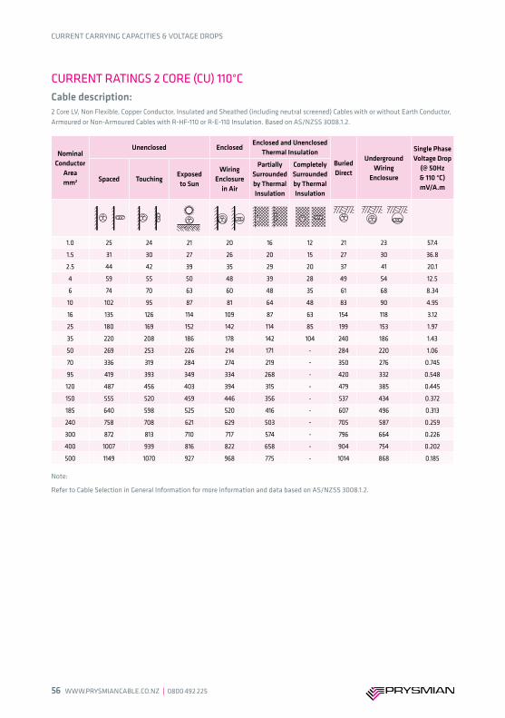
56 WWW.PRYSMIANCABLE.CO.NZ ∣ 0800 492 225
CURRENT CARRYING CAPACITIES & VOLTAGE DROPS
CURRENT RATINGS 2 CORE (CU) 110°CCable description: 2 Core LV, Non Flexible, Copper Conductor, Insulated and Sheathed (including neutral screened) Cables with or without Earth Conductor, Armoured or Non-Armoured Cables with R-HF-110 or R-E-110 Insulation. Based on AS/NZSS 3008.1.2.
Nominal Conductor
Areamm2
Unenclosed EnclosedEnclosed and Unenclosed
Thermal InsulationBuried Direct
Underground Wiring
Enclosure
Single Phase Voltage Drop
(@ 50Hz& 110 °C)mV/A.m
Spaced TouchingExposed to Sun
WiringEnclosure
in Air
Partially Surrounded by Thermal Insulation
Completely Surrounded by Thermal Insulation
1.0 25 24 21 20 16 12 21 23 57.4
1.5 31 30 27 26 20 15 27 30 36.8
2.5 44 42 39 35 29 20 37 41 20.1
4 59 55 50 48 39 28 49 54 12.5
6 74 70 63 60 48 35 61 68 8.34
10 102 95 87 81 64 48 83 90 4.95
16 135 126 114 109 87 63 154 118 3.12
25 180 169 152 142 114 85 199 153 1.97
35 220 208 186 178 142 104 240 186 1.43
50 269 253 226 214 171 - 284 220 1.06
70 336 319 284 274 219 - 350 276 0.745
95 419 393 349 334 268 - 420 332 0.548
120 487 456 403 394 315 - 479 385 0.445
150 555 520 459 446 356 - 537 434 0.372
185 640 598 525 520 416 - 607 496 0.313
240 758 708 621 629 503 - 705 587 0.259
300 872 813 710 717 574 - 796 664 0.226
400 1007 939 816 822 658 - 904 754 0.202
500 1149 1070 927 968 775 - 1014 868 0.185
Note:
Refer to Cable Selection in General Information for more information and data based on AS/NZSS 3008.1.2.

0800 492 225 ∣ WWW.PRYSMIANCABLE.CO.NZ 57
CURRENT CARRYING CAPACITIES & VOLTAGE DROPS
CURRENT RATINGS 3 & 4 CORE (CU) 75°CCable description: 3 & 4 Core LV, Non Flexible, Copper Conductor, Insulated and Sheathed (including neutral screened) Cables with or without Earth Conductor, Armoured or Non-Armoured Cables with V-75, V-90, V-90HT PVC, HFI-75-TP or HFI-90-TP LSOH Insulation. Based on AS/NZSS 3008.1.2.
Nominal Conductor
Areamm2
Unenclosed EnclosedUnenclosed
Thermal InsulationBuried Direct
Underground Wiring
Enclosure
Three Phase Voltage Drop
(@ 50Hz& 75 °C)mV/A.m
Spaced TouchingExposed to Sun
Wiring Enclosure
in Air
Partially Surrounded by Thermal Insulation
Completely Surrounded by Thermal Insulation
1.0 15 14 10 13 10 7 15 15 44.7
1.5 18 17 14 16 14 9 20 20 28.6
2.5 26 25 19 23 19 13 28 28 15.6
4 35 33 26 29 26 17 36 36 9.71
6 46 42 33 38 34 22 46 46 6.49
10 62 58 44 50 47 29 61 61 3.86
16 82 78 58 66 62 39 106 80 2.43
25 111 104 76 87 83 52 138 103 1.54
35 137 128 93 107 103 64 165 125 1.11
50 166 156 113 128 124 - 196 150 0.829
70 211 196 140 162 157 - 241 187 0.583
95 260 243 171 202 194 - 289 229 0.431
120 302 282 196 230 226 - 330 261 0.351
150 345 321 221 260 258 - 370 293 0.296
185 397 369 251 300 295 - 417 334 0.251
240 470 437 292 360 350 - 482 395 0.210
300 538 499 328 - - - 542 444 0.186
400 620 575 372 - - - 613 515 0.168
500 702 651 414 - - - 682 574 0.156
Note:
Refer to Cable Selection in General Information for more information and data based on AS/NZSS 3008.1.2.

58 WWW.PRYSMIANCABLE.CO.NZ ∣ 0800 492 225
CURRENT CARRYING CAPACITIES & VOLTAGE DROPS
CURRENT RATINGS 3 & 4 CORE (CU) 90°CCable description: 3 & 4 Core LV, Non Flexible, Copper Conductor, Insulated and Sheathed (including neutral screened) Cables with or without Earth Conductor, Armoured or Non-Armoured Cables with X-90 XLPE, R-EP-90 EPR, R-CPE-90, R-CSP-90, or R-HF-90 LSOH Insulation. Based on AS/NZSS 3008.1.2.
Nominal Conductor
Areamm2
Unenclosed EnclosedUnenclosed
Thermal InsulationBuried Direct
Underground Wiring
Enclosure
Three Phase Voltage Drop
(@ 50Hz& 90 °C)mV/A.m
Spaced TouchingExposed to Sun
Wiring Enclosure
in Air
Partially Surrounded by Thermal Insulation
Completely Surrounded by Thermal Insulation
1.0 18 15 14 14 13 8 17 17 46.8
1.5 22 21 18 18 17 10 21 21 30.0
2.5 31 29 25 26 23 14 31 31 16.4
4 42 39 33 33 31 20 40 40 10.2
6 53 50 43 42 40 24 49 49 6.80
10 73 68 58 58 54 34 67 67 4.05
16 97 91 77 75 73 45 118 87 2.55
25 131 122 103 100 98 62 153 114 1.61
35 162 151 127 125 121 76 184 139 1.17
50 198 185 154 150 147 - 218 166 0.868
70 252 234 195 190 187 - 269 207 0.609
95 311 289 239 230 231 - 323 249 0.450
120 363 337 276 271 270 - 368 289 0.366
150 415 385 314 305 308 - 412 325 0.307
185 480 444 360 354 355 - 465 372 0.259
240 569 527 424 425 421 - 539 440 0.216
300 653 604 483 - - - 607 495 0.190
400 754 695 552 - - - 685 561 0.171
500 857 790 623 - - - 764 643 0.158
Note:
Refer to Cable Selection in General Information for more information and data based on AS/NZSS 3008.1.2.

0800 492 225 ∣ WWW.PRYSMIANCABLE.CO.NZ 59
CURRENT CARRYING CAPACITIES & VOLTAGE DROPS
CURRENT RATINGS 3 & 4 CORE (CU) 110°CCable description: 3 & 4 Core LV, Non Flexible, Copper Conductor, Insulated and Sheathed (including neutral screened) Cables with or without Earth Conductor, Armoured or Non-Armoured Cables with R-HF-110 or R-E-110 Insulation. Based on AS/NZSS 3008.1.2.
Nominal Conductor
Areamm2
Unenclosed EnclosedEnclosed and Unenclosed
Thermal InsulationBuried Direct
Underground Wiring
Enclosure
Single Phase Voltage Drop
(@ 50Hz& 110 °C)mV/A.m
Spaced TouchingExposed to Sun
Wiring Enclosure
in Air
Partially Surrounded by Thermal Insulation
Completely Surrounded by Thermal Insulation
1.0 21 19 18 17 14 10 18 20 49.7
1.5 27 26 24 21 17 13 22 25 31.9
2.5 37 35 32 31 25 18 32 35 17.4
4 50 47 43 41 32 24 41 46 10.8
6 63 60 54 50 41 30 52 56 7.22
10 87 81 74 68 55 41 69 75 4.29
16 114 108 97 92 73 54 129 99 2.70
25 154 144 129 124 100 72 167 129 1.71
35 189 178 158 150 120 89 201 155 1.24
50 231 216 193 186 149 - 240 188 0.920
70 291 273 243 232 185 - 294 230 0.645
95 361 336 297 289 231 - 353 283 0.475
120 418 389 345 333 266 - 402 322 0.385
150 478 445 393 385 308 - 452 367 0.322
185 551 513 450 440 352 - 510 414 0.271
240 654 607 531 533 426 - 591 491 0.224
300 750 696 607 - - - 667 553 0.196
400 867 804 697 - - - 756 644 0.175
500 985 912 789 - - - 845 721 0.160
Note:
Refer to Cable Selection in General Information for more information and data based on AS/NZSS 3008.1.2.

60 WWW.PRYSMIANCABLE.CO.NZ ∣ 0800 492 225
CURRENT CARRYING CAPACITIES & VOLTAGE DROPS
CURRENT RATINGS AERIAL COPPER CONDUCTORCable description: LV Aerial Cables, with Copper Conductor and PVC Insulation.
CURRENT RATINGS AERIAL ALUMINIUM CONDUCTORCable description: LV Aerial Cables with Aluminium Conductor and PVC Insulation.
Nominal Conductor Area
mm2
PVC Insulated, exposed to sunVoltage Drop
(@50Hz & 75ºC)mV/A.m
Single Core2 m/s wind
2 Core Twisted, and 2 or 3 Core Parallel
Webbed Cable2 m/s wind
3 and 4 Core Twisted Cable
2 m/s windSingle Phase Three Phase
6 90 67 64 7.75 6.71
10 124 91 87 4.63 4.01
16 165 122 114 2.94 2.55
25 218 162 152 1.93 1.67
35 264 195 182 1.45 1.26
50 315 234 219 1.14 0.988
70 396 293 276 0.886 0.767
Code name Nominal
Conductor Areamm2
Current Rating Sill Air (Amps)
Current Rating 1 m/s (Amps)
NAMU 24.5 92 152
KUTU 49.5 146 233
FLY 63.6 172 272
RANGO 73.6 190 298
WASP 106 242 369
BEETLE 109 243 371
WEKE 122 267 401
WETA 167 329 487
Note:
Refer to Cable Selection in General Information for more information and data based on AS/NZSS 3008.1.2.
Note:
Current ratings are based on an ambient temperature of 30°C, a maximum conductor temperature of 75°C and intensity of solar radiation at 1000 W/m².

0800 492 225 ∣ WWW.PRYSMIANCABLE.CO.NZ 61
CURRENT CARRYING CAPACITIES & VOLTAGE DROPS
CURRENT RATINGS FLEXIBLE CORDSNominal
Conductor Areamm2
Current Carrying CapacityA
Single Phase Voltage Drop(@50Hz & 75°C)
mV/A.m
Three Phase Voltage Drop(@50Hz & 75°C)
mV/A.m
0.5 (See Note 2) 3 94.9 82.2
0.75 7.5 63.3 54.8
1.0 10 47.5 41.1
1.5 16 32.3 28.0
2.5 20 19.4 16.8
4.0 25 12.0 10.4
Note:
Refer to Cable Selection in General Information for more information and data based on AS/NZSS 3008.1.2.
Note:
1. Where a flexible cord is wound on a drum, multiply current-carrying capacity by the appropriate factor, as follows: Number of layers: 1 2 3 4 Derating factor: 0.76 0.58 0.47 0.40
2. Not applicable for tinsel conductor.3. Refer to Cable Selection in General Information for more information and data based on AS/NZSS 3008.1.2.
CURRENT RATINGS FLEXIBLE CABLE 90°CCable description: 3 Single Core LV, Copper Conductor, Sheathed and Unsheathed, Non-Armoured Cables with X-90 Insulation.
Nominal Conductor
Areamm2
Unenclosed Enclosed Thermal Insulation
Buried Direct
Underground Wiring
Enclosure
Three Phase Voltage Drop
(@ 50Hz & 90°C)mV/A.mSpaced
Spaced from
SurfaceTouching
Exposed to Sun
Wiring Enclosure
in Air
Partially Surrounded by Thermal Insulation
Completely Surrounded by Thermal Insulation
10 88 76 70 53 61 50 35 72 71 85 4.22 4.22
16 117 100 94 69 80 64 47 125 91 108 2.68 2.68
25 156 133 125 91 103 85 64 162 117 141 1.73 1.74
35 195 166 155 113 130 106 79 193 143 169 1.24 1.24
50 245 210 196 141 158 125 - 229 174 203 0.869 0.875
70 311 265 248 177 201 161 - 280 217 248 0.622 0.630
95 375 319 298 211 235 194 - 335 254 295 0.483 0.492
120 447 381 354 249 282 230 - 381 299 342 0.388 0.399
150 517 440 409 286 320 260 - 428 338 383 0.325 0.338
185 594 505 470 326 367 295 484 382 442 0.280 0.295
240 716 608 565 387 430 352 - 560 445 510 0.233 0.251
300 827 701 650 442 504 413 - 630 513 591 0.207 0.227
400 1000 840 780 525 586 470 - 715 593 670 0.183 0.204
500 1168 972 903 601 693 557 - 805 687 756 0.169 0.192
630 1382 1133 1052 693 791 628 - 902 780 877 0.157 0.181

62 WWW.PRYSMIANCABLE.CO.NZ ∣ 0800 492 225
CURRENT CARRYING CAPACITIES & VOLTAGE DROPS
Note:
Refer to Cable Selection in General Information for more information and data based on AS/NZSS 3008.1.2.
CURRENT RATINGS FLEXIBLE CABLE 110°CCable description: 3 Single Core LV, Copper Conductor, Sheathed and Unsheathed, Non-Armoured Cables with X-HF-110 or R-E-110 Insulation.
Nominal Conductor
Areamm2
Unenclosed Enclosed Thermal Insulation
Buried Direct
Underground Wiring
Enclosure
Three Phase Voltage Drop
(@ 50Hz & 110°C)
mV/A.mSpaced
Spaced from
SurfaceTouching
Exposed to Sun
Wiring Enclosure
in Air
Partially Surrounded by Thermal Insulation
Completely Surrounded by Thermal Insulation
10 106 91 86 72 75 61 43 75 81 93 4.48 4.48
16 139 120 112 94 97 79 57 138 103 122 2.84 2.85
25 185 159 149 124 129 107 77 178 133 157 1.84 1.84
35 229 197 184 153 158 129 94 213 160 187 1.31 1.31
50 289 249 232 192 203 156 - 251 199 225 0.921 0.926
70 364 312 292 240 250 200 - 308 243 275 0.658 0.665
95 439 378 352 288 296 244 - 369 284 334 0.509 0.518
120 521 447 417 339 354 288 - 420 335 378 0.408 0.419
150 601 516 482 391 404 327 - 472 378 424 0.340 0.353
185 689 592 552 446 469 384 - 533 428 489 0.293 0.307
240 829 712 663 534 576 470 - 618 510 565 0.242 0.259
300 958 820 764 612 655 536 - 696 575 654 0.213 0.232
400 1155 982 915 730 810 615 - 791 687 742 0.187 0.208
500 1348 1138 1059 841 924 740 - 894 773 864 0.172 0.194
630 1598 1327 1235 977 1063 842 - 1004 878 975 0.159 0.182

0800 492 225 ∣ WWW.PRYSMIANCABLE.CO.NZ 63
CURRENT CARRYING CAPACITIES & VOLTAGE DROPS
CURRENT RATINGS FLEXIBLE CABLE 75°CCable description: PVC Insulated LV Flexible Cables with Copper Conductor.
Nominal Conduc-tor Area
mm2
Protected from Sun Exposed to Sun
1 PhaseVoltage
Drop(@ 50Hz & 75ºC)
mV/A.m
3 Phase Voltage Drop
(@ 50Hz & 75ºC)mV/A.m
3 Phase Voltage
Drop(@ 50Hz & 75ºC)
mV/A.m
2 Single Core
3 Single Core
2 Core3 and 4
Core2 Single
Core3 Single
Core2 Core
3 and 4 Core
Single Core2, 3 and 4 Core
1.5 19 19 21 18 11 11 16 14 32.3 28.0 28.0 28.0
2.5 25 25 29 24 15 15 22 18 19.4 16.8 16.8 16.8
4 34 34 38 32 19 19 30 25 12.0 10.4 10.4 10.4
6 43 43 48 41 24 24 36 32 8.03 6.95 6.96 6.95
10 62 62 67 58 33 33 51 43 4.65 4.03 4.03 4.03
16 81 81 89 76 43 43 67 57 2.96 2.56 2.56 2.55
25 107 107 119 101 56 56 88 74 1.91 1.65 1.66 1.65
35 133 133 146 125 67 67 107 91 1.36 1.18 1.18 1.18
50 168 168 184 157 83 83 133 114 0.960 0.831 0.837 0.827
70 211 211 230 197 101 101 165 140 0.688 0.596 0.603 0.591
95 254 254 275 236 119 119 194 165 0.535 0.463 0.473 0.457
120 302 301 325 278 137 137 227 193 0.431 0.373 0.385 0.367
150 349 348 372 319 154 154 257 219 0.361 0.313 0.327 0.306
185 400 399 422 363 171 170 287 245 0.314 0.272 0.287 0.264
240 481 479 500 431 197 196 335 286 0.262 0.227 0.245 0.219
Note:
Refer to Cable Selection in General Information for more information and data based on AS/NZSS 3008.1.2.

64 WWW.PRYSMIANCABLE.CO.NZ ∣ 0800 492 225
CURRENT CARRYING CAPACITIES & VOLTAGE DROPS
CURRENT RATINGS ELASTOMERIC FLEX 90°CCable description: Elastomer Insulated Flexible Cables with Copper Conductor, R-EP-90, R-CSP-90 or R-CPE-90 Insulation.
Nominal Conduc-tor Area
mm2
Protected from Sun Exposed to Sun
1 Phase Voltage
Drop(@ 50Hz & 90ºC)mV/A.m
3 Phase Voltage Drop
(@ 50Hz & 90ºC)mV/A.m
3 Phase Voltage
Drop(@ 50Hz & 90ºC)mV/A.m
2 Single Core
3 Single Core
2 Core3 and 4
Core2 Single
Core3 Single
Core2 Core
3 and 4 Core
Single CoreMulti-
core
1.5 22 22 25 21 18 18 22 19 33.9 29.4 29.4 29.4
2.5 30 30 33 29 23 23 29 24 20.3 17.6 17.6 17.6
4 40 40 44 37 30 30 39 32 12.6 10.9 10.9 10.9
6 51 51 56 47 37 37 48 41 8.42 7.29 7.29 7.29
10 70 70 79 67 53 53 68 57 4.87 4.22 4.22 4.22
16 94 94 106 89 69 69 90 76 3.09 2.68 2.68 2.68
25 125 125 41 119 91 91 119 101 2.00 1.73 1.74 1.73
35 155 155 174 149 113 113 147 124 1.43 1.24 1.24 1.23
50 196 196 219 187 141 141 184 156 1.00 0.869 0.875 0.866
70 248 248 276 235 177 177 230 195 0.718 0.622 0.630 0.618
95 298 298 330 282 211 211 273 232 0.558 0.483 0.492 0.477
120 354 354 391 333 249 249 321 273 0.448 0.388 0.399 0.383
150 410 409 449 383 286 286 366 311 0.375 0.325 0.338 0.318
185 471 470 570 444 326 326 415 352 0.323 0.280 0.295 0.273
240 567 565 609 527 388 387 491 417 0.269 0.233 0.251 0.225
300 653 650 696 604 444 442 558 473 0.239 0.207 0.227 0.198
400 787 780 826 695 528 525 657 554 0.211 0.183 0.204 0.174
500 913 903 948 790 607 607 747 630 0.195 0.169 0.192 0.16
630 1066 1052 - - 703 693 - - 0.181 0.157 0.181 -
Note:
Refer to Cable Selection in General Information for more information and data based on AS/NZSS 3008.1.2.

0800 492 225 ∣ WWW.PRYSMIANCABLE.CO.NZ 651300 300 304 | WWW.PRYSMIAN.COM.AU 81
CURRENT CARRYING CAPACITIES & VOLTAGE DROPS
DERATING FACTORS SINGLE CORE
Derating factors for groups of circuits of cables buried direct in the ground - Single Core cables.
DERATING FACTORS MULTICORE
Derating factors for groups of circuits of cables buried direct in the ground - Multicore cables.
Number Of Circuits
Derating factors
Touching Distance (S), m
Trefoil Laid flat 0.15 0.30 0.45 0.60
2 0.78 0.81 0.83 0.88 0.91 0.93
3 0.66 0.70 0.73 0.79 0.84 0.87
4 0.61 0.64 0.68 0.74 0.81 0.85
5 0.56 0.60 0.64 0.73 0.79 0.83
6 0.53 0.57 0.61 0.71 0.78 0.82
7 0.50 0.54 0.59 0.69 0.76 0.82
8 0.49 0.53 0.57 0.68 0.76 0.81
9 0.47 0.51 0.56 0.67 0.75 0.81
10 0.46 0.50 0.55 0.67 0.75 0.80
11 0.44 0.49 0.54 0.66 0.74 0.80
12 0.43 0.48 0.53 0.66 0.74 0.80
Number Of Cables In Group
Derating factors
TouchingDistance (S), m
0.15 0.30 0.45 0.60
2 0.81 0.87 0.91 0.93 0.95
3 0.70 0.78 0.84 0.88 0.90
4 0.63 0.74 0.81 0.86 0.89
5 0.59 0.70 0.78 0.84 0.87
6 0.55 0.68 0.77 0.83 0.87
7 0.52 0.66 0.75 0.82 0.86
8 0.50 0.64 0.75 0.81 0.86
9 0.48 0.63 0.74 0.81 0.85
10 0.47 0.62 0.73 0.80 0.85
11 0.45 0.61 0.73 0.80 0.85
12 0.44 0.60 0.72 0.80 0.84
10
1SA
LES 13
00
30
0 3
04
10
0SA
LES 13
00
30
0 3
04
DERATING FACTORSM
ULTICORE
Derating factors for groups of circuits of cables buried direct in the
ground – Multicore cables.
Derating factorsNumber of
TouchingDistance (S), m
cables in group 0.15 0.30 0.45 0.60
2 0.81 0.87 0.91 0.93 0.953 0.70 0.78 0.84 0.88 0.904 0.63 0.74 0.81 0.86 0.895 0.59 0.70 0.78 0.84 0.876 0.55 0.68 0.77 0.83 0.877 0.52 0.66 0.75 0.82 0.868 0.50 0.64 0.75 0.81 0.869 0.48 0.63 0.74 0.81 0.8510 0.47 0.62 0.73 0.80 0.8511 0.45 0.61 0.73 0.80 0.8512 0.44 0.60 0.72 0.80 0.84
S
DERATING FACTORSSINGLE CORE
Derating factors for groups of circuits of cables buried direct in the
ground – Single Core cables.
Derating factorsNumber of
Circuits Touching Distance (S), mTrefoil Laid flat 0.15 0.30 0.45 0.60
2 0.78 0.81 0.83 0.88 0.91 0.933 0.66 0.70 0.73 0.79 0.84 0.874 0.61 0.64 0.68 0.74 0.81 0.855 0.56 0.60 0.64 0.73 0.79 0.836 0.53 0.57 0.61 0.71 0.78 0.827 0.50 0.54 0.59 0.69 0.76 0.828 0.49 0.53 0.57 0.68 0.76 0.819 0.47 0.51 0.56 0.67 0.75 0.8110 0.46 0.50 0.55 0.67 0.75 0.8011 0.44 0.49 0.54 0.66 0.74 0.8012 0.43 0.48 0.53 0.66 0.74 0.80
SS
PC
350_Prysm
ian_TechC
ableGuide_2010_P
C350_P
rysmian_T
echCableG
uide_2010.qxd 20/08/10 4:40 PM
Page 100
10
1SA
LES 13
00
30
0 3
04
10
0SA
LES 13
00
30
0 3
04
DERATING FACTORSM
ULTICORE
Derating factors for groups of circuits of cables buried direct in the
ground – Multicore cables.
Derating factorsNumber of
TouchingDistance (S), m
cables in group 0.15 0.30 0.45 0.60
2 0.81 0.87 0.91 0.93 0.953 0.70 0.78 0.84 0.88 0.904 0.63 0.74 0.81 0.86 0.895 0.59 0.70 0.78 0.84 0.876 0.55 0.68 0.77 0.83 0.877 0.52 0.66 0.75 0.82 0.868 0.50 0.64 0.75 0.81 0.869 0.48 0.63 0.74 0.81 0.8510 0.47 0.62 0.73 0.80 0.8511 0.45 0.61 0.73 0.80 0.8512 0.44 0.60 0.72 0.80 0.84
S
DERATING FACTORSSINGLE CORE
Derating factors for groups of circuits of cables buried direct in the
ground – Single Core cables.
Derating factorsNumber of
Circuits Touching Distance (S), mTrefoil Laid flat 0.15 0.30 0.45 0.60
2 0.78 0.81 0.83 0.88 0.91 0.933 0.66 0.70 0.73 0.79 0.84 0.874 0.61 0.64 0.68 0.74 0.81 0.855 0.56 0.60 0.64 0.73 0.79 0.836 0.53 0.57 0.61 0.71 0.78 0.827 0.50 0.54 0.59 0.69 0.76 0.828 0.49 0.53 0.57 0.68 0.76 0.819 0.47 0.51 0.56 0.67 0.75 0.8110 0.46 0.50 0.55 0.67 0.75 0.8011 0.44 0.49 0.54 0.66 0.74 0.8012 0.43 0.48 0.53 0.66 0.74 0.80
SS
PC
350_Prysm
ian_TechC
ableGuide_2010_P
C350_P
rysmian_T
echCableG
uide_2010.qxd 20/08/10 4:40 PM
Page 100

66 WWW.PRYSMIANCABLE.CO.NZ ∣ 0800 492 22582 WWW.PRYSMIAN.COM.AU | 1300 300 304
CURRENT CARRYING CAPACITIES & VOLTAGE DROPS
DERATING FACTORS SINGLE CORE ENCLOSED
Derating factors for groups of circuits of cables installed in underground wiring enclosures - Single Core cables enclosed separately.
DERATING FACTORS MULTICORE ENCLOSED
Derating factors for groups of circuits of cables installed in underground wiring enclosures - Multicore cables enclosed separately or more than one Single Core cable per wiring enclosure.
Number Of Circuits
Derating factors
TouchingDistance (S), m
0.30 0.45 0.60
2 0.90 0.93 0.95 0.96
3 0.83 0.88 0.91 0.93
4 0.79 0.85 0.89 0.92
5 0.75 0.83 0.88 0.91
6 0.73 0.82 0.87 0.90
7 0.71 0.81 0.86 0.89
8 0.70 0.80 0.85 0.89
9 0.68 0.79 0.85 0.89
10 0.67 0.79 0.85 0.89
11 0.66 0.78 0.84 0.88
12 0.66 0.78 0.84 0.88
Number Of Circuits
Derating factors
TouchingDistance (S), m
0.45 0.60
2 0.87 0.91 0.93
3 0.78 0.84 0.87
4 0.74 0.81 0.85
5 0.70 0.79 0.83
6 0.69 0.78 0.82
7 0.67 0.76 0.82
8 0.66 0.76 0.81
9 0.65 0.75 0.81
10 0.64 0.75 0.80
11 0.63 0.74 0.80
12 0.63 0.74 0.80
SALES 1
30
0 3
00
30
4SA
LES 13
00
30
0 3
04
10
3
DERATING FACTORSM
ULTICORE ENCLOSED
Derating factors for groups of circuits of cables installed in
underground wiring enclosures – M
ulticore cables enclosedseparately or m
ore than one Single Core cable per wiring enclosure.
Derating factorNumber of
TouchingDistance (S), m
Circuits 0.30 0.45 0.60
2 0.90 0.93 0.95 0.963 0.83 0.88 0.91 0.934 0.79 0.85 0.89 0.925 0.75 0.83 0.88 0.916 0.73 0.82 0.87 0.907 0.71 0.81 0.86 0.898 0.70 0.80 0.85 0.899 0.68 0.79 0.85 0.8910 0.67 0.79 0.85 0.8911 0.66 0.78 0.84 0.8812 0.66 0.78 0.84 0.88
S S
10
2 DERATING FACTORSSINGLE CORE ENCLOSED
Derating factors for groups of circuits of cables installed
in underground wiring enclosures – Single Core cables enclosed
separately.Derating factorsNumber of
CircuitsTouching
Distance (S), m0.45 0.60
2 0.87 0.91 0.933 0.78 0.84 0.874 0.74 0.81 0.855 0.70 0.79 0.836 0.69 0.78 0.827 0.67 0.76 0.828 0.66 0.76 0.819 0.65 0.75 0.8110 0.64 0.75 0.8011 0.63 0.74 0.8012 0.63 0.74 0.80
S
PC
350_Prysm
ian_TechC
ableGuide_2010_P
C350_P
rysmian_T
echCableG
uide_2010.qxd 20/08/10 4:40 PM
Page 102

0800 492 225 ∣ WWW.PRYSMIANCABLE.CO.NZ 67
CURRENT CARRYING CAPACITIES & VOLTAGE DROPS
RATING FACTORS AIR/CONCRETE SLAB
Rating factors for variations in ambient temperature for cables in air or heated concrete slabs.
Conductor Temp°C
Rating Factor
Air Ambient Temperature (see Note 1), °C
15 20 25 30 35 40 45 50 55 60 65 70 75 80 85 90 100
110 1.08 1.06 1.03 1.0 0.97 0.93 0.90 0.87 0.83 0.79 0.75 0.71 0.66 0.61 0.56 0.50 0.36
90 1.15 1.09 1.05 1.0 0.95 0.91 0.85 0.80 0.74 0.66 0.59 0.52 0.43 0.31 0.17 - -
80 1.17 1.12 1.06 1.0 0.95 0.89 0.82 0.75 0.68 0.59 0.50 0.40 0.24 - - - -
75 1.18 1.12 1.06 1.0 0.94 0.88 0.80 0.72 0.63 0.53 0.43 0.32 - - - - -
RATING FACTORS BURIED
Rating factors for variations in soil ambient temperature for cables buried direct in ground or in underground wiring enclosures.
Conductor Temp
°C
Rating Factor
Soil Ambient Temperature, °C
10 15 20 25 30 35 40
110 1.02 1.00 0.97 0.95 0.92 0.89 0.86
90 1.04 1.00 0.96 0.93 0.91 0.87 0.83
80 1.04 1.00 0.95 0.92 0.88 0.83 0.78
75 1.04 1.00 0.95 0.91 0.86 0.81 0.75
Rating factors for variations in depth of laying for cables buried direct in the ground - Single Core or Multicore.
Depth Of laying(see note 2)
m
Rating Factor
Conductor size, mm2
Up to 50 Above 50 up to 300 Above 300
0.5 1.00 1.00 1.00
0.6 0.99 0.98 0.97
0.8 0.97 0.96 0.94
1.0 0.95 0.94 0.92
1.25 0.94 0.92 0.90
1.5 0.93 0.91 0.89
1.75 0.92 0.89 0.87
2.0 0.91 0.88 0.86
2.5 0.90 0.87 0.85
3.0 or more 0.89 0.86 0.83
Note:
1. For heated concrete slabs, the ambient temperature shall be taken as the operating temperature of the slab.
Note:
1. The ambient temperature at the surfaace is to be taken at 30°C and not 15°C as at a depth of 0.5m.2. Measured to centre of enclosure of trefoil group of cables.

68 WWW.PRYSMIANCABLE.CO.NZ ∣ 0800 492 225
CURRENT CARRYING CAPACITIES & VOLTAGE DROPS
Rating factors for variations in depth of laying for cables installed in underground wiring enclosures - Single Core or Multicore cables.
Rating factors for cables buried direct in ground and for cables installed in underground wiring enclosures where the thermal resistivity of the soil varies from 1.2°C.m/W.
*These rating factors apply to single-core cables enclosed separately, or grouped in a single wiring enclosure.
Depth Of Laying(see note 2)
m
Rating Factor
Single Core* Multicore
0.5 1.00 1.00
0.6 0.98 0.99
0.8 0.95 0.97
1.0 0.93 0.96
1.25 0.90 0.95
1.5 0.89 0.94
1.75 0.88 0.94
2.0 0.87 0.93
2.5 0.86 0.93
3.0 or more 0.85 0.92
Rating Factor
Thermal Resistivity Of Soil
°C.m/W
Multicore Cable Buried Direct
Two Or Three Single-Core Cable
Buried Direct
Multicore Cable In A Wiring Enclosure
Two Single-Core Cables In A Wiring
Enclosure*
Three Single-Core Cables In A Wiring
Enclosure*
0.8 1.09 1.16 1.03 1.06 1.08
0.9 1.07 1.11 1.02 1.04 1.06
1.0 1.04 1.07 1.02 1.03 1.04
1.2 1.00 1.00 1.00 1.00 1.00
1.5 0.92 0.90 0.95 0.94 0.92
2.0 0.81 0.80 0.88 0.86 0.83
2.5 0.74 0.72 0.83 0.80 0.77
3.0 0.69 0.66 0.78 0.75 0.71
*These rating factors apply to single-core cables enclosed separately, or grouped in a single wiring enclosure.
Note:
1. The ambient temperature at the surface is to be taken at 30°C and not 15°C as at a depth of 0.5m. For depth less than 0.5m, see Table 3(4) of AS/NZS 3008.1.2.
2. Measured to centre of enclosure of trefoil group of enclosures.
RATING FACTORS UNDERGROUND ENCLOSURES

0800 492 225 ∣ WWW.PRYSMIANCABLE.CO.NZ 69
Cables in Conduits

70 WWW.PRYSMIANCABLE.CO.NZ ∣ 0800 492 22586 WWW.PRYSMIAN.COM.AU | 1300 300 304
Effective Cross Sectional Areas of PVC Cables
Appendix C6 of AS/NZS 3000.2007 gives comprehensive guidance on the number of cables installed in conduits. The basis to the calculation for the number of cables is:
The number of cables that can be installed in a circular conduit is determined from the ratios of the cross-sectional areas of the enclosure and the cable as follows:
Number of cables = x space factor
where the space factor recognises the reduction of space available from the circular geometry of the cables and enclosures:
For one cable in enclosure: 0.5 For two cables in enclosure: 0.33 For three or more cables in enclosure: 0.4
It is recommended that the installer refer to tables C9-C11 of AS/NZS 3000 for further guidance.
internal cross-sectional area of enclosurecross-sectional area of cable

0800 492 225 ∣ WWW.PRYSMIANCABLE.CO.NZ 7186 WWW.PRYSMIAN.COM.AU | 1300 300 304
Effective Cross Sectional Areas of PVC Cables
Appendix C6 of AS/NZS 3000.2007 gives comprehensive guidance on the number of cables installed in conduits. The basis to the calculation for the number of cables is:
The number of cables that can be installed in a circular conduit is determined from the ratios of the cross-sectional areas of the enclosure and the cable as follows:
Number of cables = x space factor
where the space factor recognises the reduction of space available from the circular geometry of the cables and enclosures:
For one cable in enclosure: 0.5 For two cables in enclosure: 0.33 For three or more cables in enclosure: 0.4
It is recommended that the installer refer to tables C9-C11 of AS/NZS 3000 for further guidance.
internal cross-sectional area of enclosurecross-sectional area of cable
General Information

72 WWW.PRYSMIANCABLE.CO.NZ ∣ 0800 492 22588 WWW.PRYSMIAN.COM.AU | 1300 300 304
Note:
The above table lists formulae commonly used for determining various parameters of an electrical system:
Where: Eo = Single phase voltage, in volts. Eg 230V.
E = Three phase line voltage, in volts. Eg 400V (E = √3 x Eo).
I = Current in amperes.
%Eff = Percent efficiency in decimals.
pf = Power factor in decimals.
kVA = Kilovolt-ampere.
hp = Horsepower (output).
kW = Kilowatts (input).
Power Output = Power Input x %Eff.
√3 = 1.732.
Desired Data Single-Phase Three-Phase
whenkVA is known
kVA · 1000Eo
kVA · 1000√3 · E
whenkW is known
kW · 1000Eo · pf
kW . 1000√3 · E · pf
when hp is known
hp · 746Eo · %Eff · pf
hp . 746√3 · E · %Eff · pf
kVA · Eo
1000 · E · √3
1000
kW · Eo · pf
1000 · E · √3 · pf
1000
hp · Eo · %Eff · pf
746 · E · √3 · %Eff · pf
746
General Information
3 PHASE FORMULAE
SALES 1
30
0 3
00
30
4SA
LES 13
00
30
0 3
04
10
9
3 PHASE FORMULAE
Desired Data Single-Phase Three-Phase
� when kVA . 1000 kVA . 1000kVA is known Eo ��3 . E
� when kW . 1000 kW . 1000kW is known Eo . pf ��3 . E . pf
� when hp . 746 hp . 746hp is known Eo . %Eff . pf ��3 . E . %Eff . pf
� . Eo � . E . ��3kVA
1000 1000� . Eo . pf � . E . ��3 . pf
kW1000 1000
� . Eo . %Eff . pf � . E . ��3 . %Eff . pfhp
746 746NOTE:The above table lists formulae commonly used for determining various parameters of an electrical systemwhere:Eo = Single phase voltage, in volts. Eg 230VE = Three phase line voltage, in volts. Eg 400V (E = ��3 x Eo)I = Current in amperes.%Eff = Percent efficiency in decimals.pf = Power factor in decimals.kVA = Kilovolt-ampere.hp = Horsepower (output).kW = Kilowatts (input).Power Output = Power Input x %Eff.��3 = 1.732
10
8 CABLES IN CONDUITS
Appendix C6 of A
S/NZS 3000.2007 gives com
prehensive guidance on the number of
cables installed in conduits. The basis to the calculation for the number of cables is:
The number of cables that can be installed in a circular conduit is determ
ined from the
ratios of the cross-sectional areas of the enclosure and the cable as follows:
internal cross-sectional area of enclosureN
umber of cables =
x space factorcross-sectional area of cable
where the space factor recognises the reduction of space available from
the circulargeom
etry of the cables and enclosures:
For one cable in enclosure:0.5
For two cables in enclosure:
0.33For three or m
ore cables in enclosure:0.4
It is recomm
ended that the installer refer to tables C9-C11 of AS/N
ZS 3000 for further guidance.
GENERALINFORMATION
PC
350_Prysm
ian_TechC
ableGuide_2010_P
C350_P
rysmian_T
echCableG
uide_2010.qxd 20/08/10 4:40 PM
Page 108

0800 492 225 ∣ WWW.PRYSMIANCABLE.CO.NZ 731300 300 304 | WWW.PRYSMIAN.COM.AU 89
GENERAL INFORMATION
Power Output Single Phase Voltage (V)
kW hp110 220 230 240 250
Current Rating* (A)
0.37 0.5 4.71 2.35 2.25 2.16 2.07
0.56 0.75 7.06 3.53 3.38 3.24 3.11
0.75 1 9.42 4.71 4.50 4.32 4.14
1.1 1.5 14.1 7.06 6.76 6.48 6.22
1.5 2 18.8 9.42 9.01 8.63 8.29
1.9 2.5 23.5 11.8 11.3 10.8 10.4
2.2 3 28.3 14.1 13.5 13.0 12.4
3.0 4 37.7 18.8 18.0 17.3 16.6
3.7 5 47.1 23.5 22.5 21.6 20.7
4.5 6 56.5 28.3 27.0 25.9 24.9
5.2 7 65.9 33.0 31.5 30.2 29.0
5.6 7.5 70.6 35.3 33.8 32.4 31.1
6.0 8 75.4 37.7 36.0 34.5 33.2
6.7 9 84.8 42.4 40.5 38.9 37.3
7.5 10 94.2 47.1 45.0 43.2 41.4
9.3 12.5 118 58.9 56.3 54.0 51.8
11.2 15 141 70.6 67.6 64.8 62.2
14.9 20 188 94.2 90.1 86.3 82.9
18.7 25 235 118 113 108 104
22.4 30 283 141 135 130 124
Power Output Three Phase Line Voltage (V)
kW hp380 400 415 440 500
Current Rating* (A)
0.37 0.5 0.79 0.75 0.72 0.68 0.60
0.56 0.75 1.18 1.12 1.08 1.02 0.90
0.75 1 1.57 1.50 1.44 1.36 1.20
1.1 1.5 2.36 2.24 2.16 2.04 1.79
1.5 2 3.15 2.99 2.88 2.72 2.39
1.9 2.5 3.94 3.74 3.60 3.40 2.99
2.2 3 4.72 4.49 4.32 4.08 3.59
3.0 4 6.30 5.98 5.77 5.44 4.79
3.7 5 7.87 7.48 7.21 6.80 5.98
4.5 6 9.44 8.97 8.65 8.16 7.18
5.2 7 11.0 10.5 10.1 9.52 8.37
5.6 7.5 11.8 11.2 10.8 10.2 8.97
6.0 8 12.6 12.0 11.5 10.9 9.57
6.7 9 14.2 13.5 13.0 12.2 10.8
7.5 10 15.7 15.0 14.4 13.6 12.0
9.3 12.5 19.7 18.7 18.0 17.0 15.0
11.2 15 23.6 22.4 21.6 20.4 17.9
14.9 20 31.5 29.9 28.8 27.2 23.9
18.7 25 39.4 37.4 36.0 34.0 29.9
22.4 30 47.2 44.9 43.2 40.8 35.9
SINGLE PHASE MOTOR CURRENT
THREE PHASE MOTOR CURRENT
*Approximate full load currents for standard AC induction motors based on power factor and efficiency of 0.8 and 0.9 respectively.

74 WWW.PRYSMIANCABLE.CO.NZ ∣ 0800 492 22590 WWW.PRYSMIAN.COM.AU | 1300 300 304
GENERAL INFORMATION
Short-Circuit Capacity* (kA) for one second.
Nominal Conductor
Areamm2
Initial Conductor Temperature
PVC Insulated Cable XLPE Insulated Cable
75°C 90°C 105°C 75°C 90°C 105°C 90°C 90°C
Copper Aluminium Copper Aluminium
1.0 0.111 0.100 0.088 0.074 0.066 0.058 0.143 0.095
1.5 0.167 0.150 0.131 0.110 0.099 0.087 0.215 0.142
2.5 0.278 0.250 0.219 0.184 0.165 0.145 0.358 0.236
4.0 0.444 0.400 0.350 0.294 0.264 0.232 0.572 0.378
6.0 0.666 0.599 0.526 0.442 0.396 0.347 0.858 0.567
10 1.11 0.999 0.876 0.736 0.660 0.579 1.43 0.945
16 1.78 1.60 1.40 1.18 1.06 0.926 2.29 1.51
25 2.78 2.50 2.19 1.84 1.65 1.45 3.58 2.36
35 3.89 3.50 3.07 2.58 2.31 2.03 5.01 3.31
50 5.55 5.00 4.38 3.68 3.30 2.90 7.15 4.73
70 7.77 6.99 6.13 5.15 4.62 4.05 10.0 6.62
95 10.5 9.49 8.32 6.99 6.27 5.50 13.6 8.98
120 13.3 12.0 10.5 8.83 7.92 6.95 17.2 11.3
150 16.7 15.0 13.1 11.0 9.90 8.69 21.5 14.2
185 20.5 18.5 16.2 13.6 12.2 10.7 26.5 17.5
240 26.6 24.0 21.0 17.7 15.8 13.9 34.3 22.7
300 33.3 30.0 26.3 22.1 19.8 17.4 42.9 28.4
400 39.5 34.2 28.3 26.1 22.6 18.7 57.2 37.8
500 49.4 42.8 35.4 32.6 28.3 23.4 71.5 47.3
630 62.2 53.9 44.6 41.1 35.7 29.5 90.1 59.5
SHORT CIRCUIT CAPACITY
Note:
1. *Short-circuit capacities are based on maximum permissible temperature limits of: 160°C for PVC insulation with conductor up to and
including 300mm2. 140°C for PVC insulation with conductor greater than 300mm2. 250°C for XLPE insulation. Short-circuit capacities
have to be derated if short-circuit temperature limits of other components of the circuit, eg., joints, are less than those stated.
2. The short-circuit capacity for durations up to and including 5 seconds may be calculated with the following formula:
lk = Ii where lk = short-circuit capacity during the time, tk.
√tk li = short-circuit capacity for 1 second.
tk= short-circuit duration, seconds.

0800 492 225 ∣ WWW.PRYSMIANCABLE.CO.NZ 751300 300 304 | WWW.PRYSMIAN.COM.AU 91
GENERAL INFORMATION
Conductor, DC Resistance to AS/NZS 1125 and Nominal Diameter.
Nominal Conductor Areamm2
Plain Copper Tinned Copper
Conductor Nominal Diameter
mm
Max. dc Resistance at 20°CΩ/km
Conductor Nominal Diameter
mm
Max. dc Resistance at 20°CΩ/km
0.5 0.89 39.0 0.89 40.1
0.75 1.09 26.0 1.09 26.7
1.0 1.26 19.5 1.26 20.0
1.5 1.54 13.3 1.51 13.7
2.5 1.98 7.98 1.95 8.21
4.0 2.51 4.95 2.48 5.09
FLEXIBLE CONDUCTORS
Nominal Conductor Areamm2
Annealed Copper Aluminium
Conductor Nominal Diameter
mm
Plain TinnedConductor Nominal
Diametermm
Max. dc Resistance at 20°CΩ/km
Max. dc Resistance at 20°CΩ/km
Max. dc Resistance at 20°CΩ/km
*1.0 1.13 18.1 18.2 - -
1.0 1.20 21.2 21.6 - -
1.5 1.50 13.6 13.8 - -
*2.5 1.78 7.41 7.56 - -
2.5 2.0 7.41 7.56 - -
4.0 2.5 4.61 4.70 - -
6.0 3.1 3.08 3.11 - -
10 4.0 1.83 1.84 - -
16 5.1 1.15 1.16 5.1 1.91
25 6.4 0.727 0.734 6.4 1.20
35 7.6 0.524 0.529 7.5 0.868
50 8.9 0.387 0.391 8.8 0.641
70 10.6 0.268 0.270 10.6 0.443
95 12.5 0.193 0.195 12.5 0.320
120 14.1 0.153 0.154 14.1 0.253
150 15.7 0.124 0.126 15.6 0.206
185 17.5 0.0991 0.100 17.5 0.164
240 20.1 0.0754 0.0762 20.1 0.125
300 22.6 0.0601 0.0607 22.4 0.100
400 25.5 0.0470 0.0475 25.5 0.0778
∆500 28.8 0.0366 0.0369 28.8 0.0605
∆630 33.0 0.0283 0.0286 32.7 0.0469
Conductor, DC Resistance to AS/NZS 1125 and Nominal Diameter.
Notes:
* Single Wire Conductor. ∆ Single core only.
NON COMPACTED CONDUCTORS

76 WWW.PRYSMIANCABLE.CO.NZ ∣ 0800 492 22592 WWW.PRYSMIAN.COM.AU | 1300 300 304
GENERAL INFORMATION
Nominal Conductor Areamm2
Plain Copper Aluminium
Conductor Nominal Diameter
mm
Max. dc Resistance at 20°CΩ/km
Conductor Nominal Diameter
mm
Max. dc Resistance at 20°CΩ/km
16 4.8 1.15 4.8 1.91
25 6.1 0.727 6.1 1.20
35 7.1 0.524 7.1 0.868
50 8.2 0.387 8.2 0.641
70 9.8 0.268 9.8 0.443
95 11.5 0.193 11.5 0.320
120 12.9 0.153 12.9 0.253
150 14.3 0.124 14.3 0.206
185 16.1 0.0991 15.9 0.164
240 18.3 0.0754 18.3 0.125
300 20.8 0.0601 20.8 0.100
400 23.5 0.0470 23.5 0.0778
∆500 26.6 0.0366 26.6 0.0605
∆630 30.2 0.0283 30.2 0.0469
Conductor, DC Resistance to AS/NZS 1125 and Nominal Diameter.
Notes:
∆ Single core only.
COMPACTED CONDUCTORS

0800 492 225 ∣ WWW.PRYSMIANCABLE.CO.NZ 771300 300 304 | WWW.PRYSMIAN.COM.AU 93
GENERAL INFORMATION
SWG Metric B&S (AWG)Approx. Diameter
mmCalculated Area
mm2
40 - - 0.122 0.0117
- - 36 .127 .0127
39 - - .132 .0137
- - 35 .142 .0159
38 - - .152 .0182
- - 34 .160 .0201
37 - - .173 .0234
- - 33 .180 .0255
38 - - .193 .0293
- 0.20 - .200 .0314
- - 32 .203 .0325
35 - - .213 .0358
- - 31 .226 .0401
34 - - .234 .0429
- 0.25 - .250 .0491
33 - 30 .254 .0507
32 - - .274 .0591
- - 29 .287 .0645
31 - - .295 .0682
- 0.30 - .300 .0707
- - - .305 .0730
30 - - .315 .0779
- - 28 .320 .0806
29 - - .345 .0937
- - 27 .361 .102
28 - - .376 .111
- 0.40 - .400 .126
- - 28 .404 .128
27 - - .417 .136
- - 26 .455 .163
26 - - .457 .164
- 0.50 - .500 .196
25 - - .508 .203
- - 24 .511 .205
24 - - .559 .245
- - 23 .574 .259
23 - - .610 .292
- - 22 .643 .324
- 0.67 - .670 .353
22 - - .711 .397
- - 21 .724 .412
- - - .737 .426
- 0.80 - .800 .503
Wire Gauges and Standard Metric Wires.
WIRE GAUGES

78 WWW.PRYSMIANCABLE.CO.NZ ∣ 0800 492 22594 WWW.PRYSMIAN.COM.AU | 1300 300 304
GENERAL INFORMATION
SWG Metric B&S (AWG)Approx. Diameter
mmCalculated Area
mm2
21 - 20 0.813 0.519
- .85 - .850 .568
- - 19 .912 .652
20 - - .914 .657
- - - 1.0 .785
19 - - 1.02 .81
- - 18 1.02 .826
- 1.04 - 1.04 .849
- - - 1.12 .981
- 1.13 - 1.13 1.00
- - 17 1.15 1.04
18 - - 1.22 1.17
- - 16 1.29 1.31
- - - 1.32 1.37
- 1.35 - 1.35 1.43
- 1.38 - 1.38 1.50
17 - - 1.42 1.59
- - 15 1.45 1.65
- 1.53 - 1.53 1.84
16 - - 1.63 2.08
- - 14 1.63 2.08
- 1.70 - 1.70 2.27
- 1.78 - 1.78 2.49
15 - 13 1.83 2.63
- - - 2.00 3.14
14 2.03 - 2.03 3.24
- - 12 2.05 3.31
- - - 2.11 3.50
- 2.14 - 2.14 3.60
- 2.25 - 2.25 3.98
- - 11 2.30 4.17
13 - - 2.34 4.29
- - - 2.36 4.38
- 2.52 - 2.52 4.99
- - 10 2.59 5.26
- - - 2.62 5.38
12 - - 2.64 5.48
- - - 2.70 5.73
- 2.85 - 2.85 6.38
- - 9 2.91 6.63
- - - 3.00 7.07
- 3.20 - 3.20 8.04
10 - - 3.25 8.30
Wire Gauges and Standard Metric Wires.
WIRE GAUGES

0800 492 225 ∣ WWW.PRYSMIANCABLE.CO.NZ 791300 300 304 | WWW.PRYSMIAN.COM.AU 95
GENERAL INFORMATION
AWGSize
CSAmm2
MCMSize
CSAmm2
MCMSize
CSAmm2
9 6.63 250 127 900 456
8 8.37 300 152 950 481
7 10.6 350 177 1000 507
6 13.3 400 203 1100 557
5 16.8 450 228 1200 608
4 21.2 500 253 1300 659
3 26.7 550 279 1400 709
2 33.6 600 304 1500 760
1 42.4 650 329 1600 811
0 53.5 700 355 1700 861
2/0 67 750 380 1800 912
3/0 85 800 405 1900 963
4/0 107 850 431 2000 1010
American Conductor Sizes in Comparison.
AMERICAN CONDUCTOR SIZES
American conductor sizes are based on American Wire Gauge (AWG) for small sizes and “circular mils” (CM) for larger sizes.“Mil” is an
engineering term for one thousandth of an inch and the “circular mil” is the area of a circle one thousandth of an inch in diameter. The
term MCM is used for one thousand circular mils.

80 WWW.PRYSMIANCABLE.CO.NZ ∣ 0800 492 22596 WWW.PRYSMIAN.COM.AU | 1300 300 304
GENERAL INFORMATION
Metric ImperialCalculated Area*
mm2Nominal Conductor Areamm2
StrandingNo./mm
Nominal Conductor Areasq. in
StrandingNo./mm
0.5 1/0.80 - - 0.503- - 0.001 1/.036 0.657
1.0 7/0.40 - - 0.862- - 0.0015 1/.044 0.981
1.0 1/1.13 - - 1.00- - 0.002 3/.029 1.28
1.5 7/0.50 - - 1.371.5 1/1.38 - - 1.50- - 0.003 3/.036 1.97- - 0.0032 1/.064 2.08
2.5 7/0.67 - - 2.472.5 1/1.78 - - 2.49- - 0.0045 7/.029 2.984 7/0.85 - - 3.97- - 0.007 7/.036 4.606 7/1.04 - - 5.95- - 0.01 7/.044 6.81- - 0.0145 7/.052 9.59
10 7/1.35 - - 10.0- - 0.0225 7/.064 14.5
16 7/1.70 - - 15.9- - 0.03 19/.044 18.6- - 0.04 19/.052 26.0
25 19/1.35 - - 27.235 19/1.53 - - 34.9- - 0.06 19/.064 39.4
50 19/1.78 - - 47.3- - 0.075 19/.072 49.9- - 0.1 19/.083 66.3
70 19/2.14 - - 68.3- - 0.12 37/.064 76.8
95 19/2.45 - - 89.6- - 0.15 37/.072 97.2
120 37/2.03 - - 120- - 0.2 37/.083 129
150 37.2.25 - - 147- - 0.25 37/.093 162
185 37/2.52 - - 185- - 0.3 37/.103 199
240 61/2.25 - - 243- - 0.4 61/.093 267
300 61/2.52 - - 304- - 0.5 61/.103 328
400 61/2.85 - - 389- - 0.6 91/.093 399- - 0.75 91/.103 489
500 61/3.20 - - 491- - 0.85 127/.093 557
630 91/3.00 - - 643- - 1.0 127/.103 683- - 1.25 127/.112 807
800 127/2.85 - - 8101000 127/3.20 - - 1020
- - 1.5 127/.128 1050
A Comparison of Metric and Imperial Conductors for Fixed Cables.
IMPERIAL CONDUCTORS
* The area has been calculated as follows:
For single wires - based on nominal wire diameter. For stranded conductors - based on nominal wire diameter and number of wires.

0800 492 225 ∣ WWW.PRYSMIANCABLE.CO.NZ 811300 300 304 | WWW.PRYSMIAN.COM.AU 97
GENERAL INFORMATION
Minimum Copper Earthing Conductor Size.
EARTH SIZE
*These earthing conductors may be used only where incorporated in a multicore cable or flexible cord, other than a lift travelling cable,
in accordance with Clause 5.3.3.4(b) & (c) AS/NZS 3000:2007, Wiring Rules.
† A larger earthing conductor may be required to Safety Clause 5.3.3.1.1 of AS/NZS 3000:2007.
Nominal Size Of ACTIVE Conductor With COPPER Active Conductor With ALUMINIUM Active Conductor
1.0 1.0* -
1.5 1.5* -
2.5 2.5 -
4.0 2.5 -
6.0 2.5 -
10 4 -
16 6 4
25 6 6
35 10 6
50 16 10
70 25 10
95 25 16
120 35 25
150 50 25
185 70 35
240 95 50
300 120 70
400 120† 95†
500 120† 95†
630 120† 120†
>630 25% of Active size† 25% of Active size†

82 WWW.PRYSMIANCABLE.CO.NZ ∣ 0800 492 22598 WWW.PRYSMIAN.COM.AU | 1300 300 304
GENERAL INFORMATION
Cable Installation:
In installing PVC sheathed cables, care should be taken to ensure that the ambient and cable temperature has been above 0ºC for the previous 24 hours to avoid the risk of cracking of the oversheath.
For groups of parallel single core circuits, the cables should be installed in close trefoil formation as hereunder:
(i) Two conductors per phase (ii) Three conductors per phase
Recommended Minimum Bending Radii
The following table sets out the recommended minimum bending radii for single or multi-core cables for working voltages up to and including 0.6/1kV. The bending radius is related to the inner surface of the cable, not the axis. Care should be taken in planning a cable installation to allow for as large a bending radius as possible, as excessive bending can be detrimental to cable life expectancy.
Where D = Overall cable diameter in mm. D*= Diameter over nylon jacket.
INSTALLATION & BENDING RADII
AB C
AB C
AB C
AC B
AC B
Cable Description During installation Fixed or Location
1. Subject to overriding requirements of items 2 to 8 listed below:
a. Overall cable diameter up to 25mm 6D 4D
b. Flexible cords or cables of all diameters 6D 4D
2. Overall cable diameter (exclude Flexible) >25mm 9D 6D
3. Mica Glass taped cables 12D 8D
4. Solid Al or Compacted (including Sector Shaped) Conductor 12D 8D
5. Armoured Cables 18D 12D
6. Metallic Screened Cables 18D 12D
7. HDPE Sheathed Cables 25D 15D
8. Nylon Covered Cables 30D* 20D*

0800 492 225 ∣ WWW.PRYSMIANCABLE.CO.NZ 831300 300 304 | WWW.PRYSMIAN.COM.AU 99
GENERAL INFORMATION
Using a pulling eye on the conductor:
Copper - 0.07 kN/mm2 of conductor3). Aluminium, Stranded - 0.05 kN/mm2 of conductor. Aluminium, Solid - 0.03 kN/mm2 of conductor.
Using a pulling eye on the Steel Wire Armour:
P = 0.005 D2.
Using a Stocking grip: (see Note 1)
P = 0.0035 D2.
Where: P = Tension in kN. D = Cable diameter in mm.
Notes:
1. When considering the use of a stocking grip the tension should not exceed the values given for a pulling eye on the conductor(s).
2. 1 kN = 102kgf.
3. Subject to a maximum of 25kN.
MAXIMUM PULLING TENSIONS

84 WWW.PRYSMIANCABLE.CO.NZ ∣ 0800 492 225100 WWW.PRYSMIAN.COM.AU | 1300 300 304
GENERAL INFORMATION
Safe Working Force of Metric Flexible Cables and Cords.
Safe Working Force of Metric Flexible Cables and Cords (Repeated Flexing).
Safe Working Force for cables subjected to straight tension without significant bending or flexing - Safety factor 4 to 1.
Safe Working Force for cables subjected to repeated reeling or bending whilst under tension - Safety factor 8 to 1.
* Where N = the number of cores of the same size.
SAFE WORKING FORCE
Nominal Conductor Area
mm2
Single CorekN
2 CorekN
3 CorekN
4 CorekN
*More Than 4 Cores
kN
0.5 0.015 0.030 0.045 0.06 0.015 x N
0.75 0.0225 0.045 0.0675 0.09 0.0225 x N
1.0 0.03 0.06 0.09 0.12 0.03 x N
1.5 0.045 0.09 0.135 0.18 0.045 x N
2.5 0.075 0.15 0.225 0.3 0.075 x N
4 0.12 0.24 0.36 0.48 0.12 x N
6 0.18 0.36 0.54 0.72 0.18 x N
10 0.3 0.6 0.90 1.2 0.3 x N
16 0.48 0.96 1.44 1.92 0.48 x N
25 0.75 1.5 2.25 3.0 0.75 x N
35 1.05 2.1 3.15 4.2 1.05 x N
50 1.5 3.0 4.5 6.0 1.5 x N
70 2.1 4.2 6.3 8.4 2.1 x N
95 2.85 5.7 8.55 11.4 2.85 x N
120 3.6 7.2 10.8 14.4 3.6 x N
150 4.5 9.0 13.5 18.0 4.5 x N
185 5.55 11.1 16.65 22.2 -
240 7.2 14.4 21.6 - -
300 9.0 18.0 - - -
Nominal Conductor Area
mm2
Single CorekN
2 CorekN
3 CorekN
4 CorekN
*More Than 4 Cores
kN
0.5 0.0075 0.015 0.0225 0.03 0.0075 x N
0.75 0.01125 0.0225 0.03375 0.045 0.01125 x N
1.0 0.015 0.03 0.045 0.06 0.015 x N
1.5 0.0225 0.045 0.0675 0.09 0.0225 x N
2.5 0.0375 0.075 0.1125 0.15 0.0375 x N
4 0.06 0.12 0.18 0.24 0.06 x N
6 0.09 0.18 0.27 0.36 0.09x x N
10 0.15 0.3 0.45 0.6 0.15 x N
16 0.24 0.48 0.72 0.96 0.24 x N
25 0.375 1.75 1.125 1.5 0.375 x N
35 0.525 1.05 1.575 2.1 0.525 x N
50 0.75 1.5 2.25 3.0 0.75 x N
70 1.05 2.1 3.15 - -
95 1.425 2.85 4.275 - -
120 1.8 3.6 5.4 - -
150 2.25 - - - -
185 2.775 - - - -
240 3.6 - - - -
300 4.5 - - - -
400 6.0 - - - -
500 7.5 - - - -

0800 492 225 ∣ WWW.PRYSMIANCABLE.CO.NZ 851300 300 304 | WWW.PRYSMIAN.COM.AU 101
GENERAL INFORMATION
Performance Rating of Cable Insulation and Sheathing Materials.
VG = very good, G = good, F = fair, P = poor.
*Refer to PVC in Glossary of Terms in this Section.
INSULATION & SHEATH PROPERTIES
MATERIAL
Rec
omm
ende
d M
ax. O
pera
ting
Tem
p.
Ozo
ne &
Par
tial
Dis
char
ge R
esis
tanc
e
Wea
ther
Res
ista
nce
Oil
Res
ista
nce
Wat
er R
esis
tanc
e
Res
ista
nce
to C
hem
ical
s
Res
ista
nce
to S
olve
nts
Abr
asio
n R
esis
tanc
e
Com
bust
ion
Pro
paga
tion
Res
ista
nce
Insu
lati
on R
esis
tanc
e
Elec
tric
Str
engt
h
PVC* - V-90 90 VG G G G G F G G G G
PVC* - V-90 HT 105*
XLPE X-90 90 F G F VG G G G P VG VG
Polyethylene LD 70 F G F VG G G G P VG VG
Polyethylene HD 90 F G F VG G G VG P VG VG
R-EP-90 90 VG VG F VG G F F P VG G
R-CSP-90, R-CPE-90 90 G G G F G G G G G G
R-HF-90, R-HF-110 90/110 VG VG F VG G F F VG G G
HD-85-PCP 85 G G G G G G G G G G
HD-90-CSP 90 G G G G G G G G G G
HF-110-R 90/110 VG VG G VG G G G VG G G
Nylon G G G G G VG VG P G G

86 WWW.PRYSMIANCABLE.CO.NZ ∣ 0800 492 225
You probably already know that we’re world leading in quality cables. But did you know that we also provide you services from start to finish – and beyond. In our offer you’ll find everything from cables cut to length to the best technical support on the market. Doing business with us pays off.
All the way.Services beyond the ordinary.

0800 492 225 ∣ WWW.PRYSMIANCABLE.CO.NZ 871300 300 304 | WWW.PRYSMIAN.COM.AU 103
GENERAL INFORMATION
Al: Aluminium conductor.
Ambient temperature for current-carrying capacity: The temperature of the medium in the immediate neighbourhood of the installed cable - a) including any increase in temperature due to materials or equipment to which the cables are connected, or are to be connected; but b) excluding any increase in temperature which may be due to the heat arising from the cables at that point.
AS/NZS 2053: Australian/New Zealand Standard - Conduits and fittings for electrical installations.
AS/NZS 3000: Wiring Rules.
AS/NZS 3008.1.1: Australian/New Zealand Standard - Electrical installations - Selection of cables Part 1.1: Cables for alternating voltages up to and including 0.6/1kV - Typical Australian installation conditions.
AS/NZS 3191: Australian/New Zealand Standard - Approval and test specification - Electric flexible cords.
AS/NZS 5000: Australian/New Zealand Standard - Electric Cables - Polymeric insulated. Part 1: For working voltages up to and including 0.6/1kV. Part 2: For working voltages up to and including 450/750V. Part 3: Multicore control cables for working voltages up to and including 450/750V.
Bending radius, installed: Refers to minimum bending radius to which the cable can be subjected to in its final position or location.
Bending radius, installing: Refers to minimum bending radius to which the cable can be subjected to during the installation process.
BW: Building wire, usually refers to single core, insulated and unsheathed cable.
Compacted conductor: A stranded conductor in which, to reduce overall dimensions, wires have been laid up and pressed together. All conductors in this technical manual are non compacted unless specified.
GLOSSARY OF TERMS
Prysmian Cables & Systems Australia Pty LtdPh: 1300 300 304 Fx: 1300 300 307 1 Heathcote Road, Liverpool 2170 NSW, AustraliaEmail: [email protected]
OPERATING TEMPERATURE
CONSTANT AT 90˚C
The faster, more flexible choice for installing cable.
Created using quality components for long-life performance, Prysmian’s new cable options offer extreme flexibility for fixed applications, in both general and fire rated projects. Easier to install in difficult areas, Prysmian’s flexible cabling is the ideal solution on projects where space - and time - are at a premium.
Introducing the new Flexible XLPE & Firestop cable range
OPERATING TEMPERATURE
CONSTANT AT 110˚C
110
OPERATING TEMPERATURE
CONSTANT AT 110˚C
110 BENDING RADIUS FOR FIXED APPLIC
ATIO
NS
FLEXIBLE XLPE CABLE
BENDING RADIUS FOR FIXED APPLIC
ATIO
NS
FLEXIBLE XLPE CABLE
BENDING RADIUS FOR FIXED APPLIC
ATIO
NS
FLEXIBLE XLPE CABLE
Flexible 90˚C XLPE
Flexible 110˚C XLPE
Flexible 110˚C Firestop
Al: Aluminium conductor.
Ambient temperature for current-carrying capacity: The temperature of the medium in the immediate neighbourhood of the installed cable - a) including any increase in temperature due to materials or equipment to which the cables are connected, or are to be connected; but b) excluding any increase in temperature which may be due to the heat arising from the cables at that point.
AS/NZS 2053: Australian/New Zealand Standard - Conduits and fittings for electrical installations.
AS/NZS 3000: Wiring Rules.
AS/NZSS 3008.1.2: Australian/New Zealand Standard - Electrical installations - Selection of cables Part 1.1: Cables for alternating voltages up to and including 0.6/1kV - Typical Australian installation conditions.
AS/NZS 3191: Australian/New Zealand Standard - Approval and test specification - Electric flexible cords.
AS/NZS 5000: Australian/New Zealand Standard - Electric Cables - Polymeric insulated. Part 1: For working voltages up to and including 0.6/1kV. Part 2: For working voltages up to and including 450/750V. Part 3: Multicore control cables for working voltages up to and including 450/750V.
Bending radius, installed: Refers to minimum bending radius to which the cable can be subjected to in its final position or location.
Bending radius, installing: Refers to minimum bending radius to which the cable can be subjected to during the installation process.
BW: Building wire, usually refers to single core, insulated and unsheathed cable.
Compacted conductor: A stranded conductor in which, to reduce overall dimensions, wires have been laid up and pressed together. All conductors in this technical manual are non compacted unless specified.

88 WWW.PRYSMIANCABLE.CO.NZ ∣ 0800 492 225
Conductor: That portion of a cable which has the specific function of carrying current.
Consumer terminals: Refer to “Point of Supply”.
CCS: Copper Covered Steel.
Cu: Copper conductor, usually refers to plain annealed copper.
HDCu: Hard drawn copper conductor, for aerial application due to its higher tensile strength.
LSOH: Low Smoke Zero Halogen.
LV: Low voltage - a.c. = 50V and ≤1000V; d.c. = >120V and ≤1500V.
Overcurrent: A current exceeding the rated value.
PACW: Plain annealed copper wire.
PE: Polyethylene (See Thermoplastic material).
Point of Supply: The junction of the electricity distributor’s conductors with the consumers mains. (Formerly known as consumers’ terminals).
PVC: Polyvinyl Chloride (See Thermoplastic material), the following grades are commonly used:
Insulation Grade Sheathing Grade Maximum continuous conductor temperature
V-90*, V-90HT* 3V-90, 5V-90 75ºC
*The use of the higher temperature insulation compounds does not permit a higher current-carrying capacity. AS/NZ 3008.1.1 recommends 75°C for current-carrying capacity calculation.
**Where it is possible to guard against plastic flow, and where reduced insulation resistance can be tolerated, V-90HT can be operated at a temperature up to 105ºC for an average of 500 hours per annum during the cable service life.
***Direct contact with polystyrene, polyurethane and similar thermal insulation material shall be avoided.
SDI: Single core double insulated cable.
GENERAL INFORMATION

Short-circuit current: A fault current resulting from a fault of negligible impedance between live conductors having a difference in potential under normal operating conditions.
Solid conductor: A conductor consisting of a single wire.
TACW: Tinned annealed copper wire.
TCu: Tinned copper conductor.
Thermoplastic material: A material that can be readily softened and resoftened by repeated heating, eg., PVC and PE.
Thermosetting material: A material which cures by chemical reaction when heated and, when cured, cannot be resoftened by heating, eg., XLPE.
Tinsel conductor: A conductor comprising fine flattened copper wires assembled in combination with textile material to achieve a high degree of flexibility.
TPS: Thermoplastic sheath. (See Thermoplastic material).
XLPE: Cross linked polyethylene. For LV application, usually refers to X-90 grade. (See Thermosetting material).
Whilst every care has been taken in the preparation of this publication, Prysmian takes no responsibility for any errors and or omissions. This booklet is intended as a guide only and reference must be made by any person using this booklet to the appropriate Australian/NZ Standard and or to local electricity supply authority rulings.
The company reserves the right to make changes in product without notice.
The Prysmian Guide to Cable has been completely revised and makes reference to the most recent information available. Information herein refers to common low voltage power and communication cables used by industry. For information not covered in this publication eg. High Voltage XLPE and EPR, Fibre Optics and other specialised Power and Communication cables please contact your nearest Prysmian Sales Office on 0800 492 225.
Copyright © Prysmian New Zealand Ltd.
All rights reserved. Subject to change without notice.
Quality ISO 9001
GENERAL INFORMATION

Prysmian New Zealand Limited
30 Binsted Road, New Lynn 0600 Auckland, New Zealand Ph: (09) 827 3109 Toll Free: 0800 492 225 E-mail: [email protected]
www.prysmiancable.co.nz
© A
ll rights reserved by Prysmian Group 20
15 | NZ V
ersion 1.
Welcome to the latest edition of the Technical Cable Guide.
Following the recent acquisition of Draka, the Prysmian Group is now the world’s largest producer of power and telecommunication cables with 97 manufacturing plants, 17 Research & Development Centres, and around 22,000 employees.
A global solutions provider, Prysmian offers a wide range of integrated solutions, such as cable systems, system design and engineering, project management, installation and postsale services.
Prysmian focuses on continuous product innovation and on achieving a competitive edge by focusing on research and development. This is done through Prysmian’s own research & development centres and by co-operating with universities, scientific institutions and our valued customers. Prysmian’s world-wide organisation makes and delivers advanced technological solutions to customers anywhere in the world.
Prysmian is committed to providing all of the necessary technical, installation, safety and practical information that may be required by designers, installers and users of our products in a comprehensive hand book that can easily be used in the field.
Please accept this latest edition of the Technical Cable Guide with our compliments.
Prysmian Cables & Systems Australia Pty Ltd proudly manufactures in Australia and operates certified management systems compliant with the requirements of;
ISO 9001:2000 Quality Management Systems AS/NZS 4801:2001 Occupational Health & Safety Management SystemsOHSAS 18001:1999 Assessment Specification for Occupational Health & Safety Management SystemsISO 14001:2004 Environmental Management Systems
WARNING
Cables must be installed according to the requirements of AS/NZS 3000, the Wiring Rules and any supplementary requirements of appropriate local Electricity Authorities, by an Electrician who holds a valid licence, appropriate to the State, Territory or Country where installation is to take place.
The Wiring Rules are applied throughout Australia by means of State and Territory Acts and Regulations. In general these Acts and Regulations specify compliance with the Rules, however, because of local requirements, some variation to specific clauses may be called for by means of these Acts and Regulations.
Note: Current ratings data contained in the cable selection category of this guide are based on Australian/New Zealand Standards (AS/NZS 3008.1.1).
1300 300 304 | WWW.PRYSMIAN.COM.AU 105
GENERAL INFORMATION
Solid conductor: A conductor consisting of a single wire.
TACW: Tinned annealed copper wire.
TCu: Tinned copper conductor.
Thermoplastic material: A material that can be readily softened and resoftened by repeated heating, eg., PVC and PE.
Thermosetting material: A material which cures by chemical reaction when heated and, when cured, cannot be resoftened by heating, eg., XLPE.
Tinsel conductor: A conductor comprising fine flattened copper wires assembled in combination with textile material to achieve a high degree of flexibility.
TPS: Thermoplastic sheath. (See Thermoplastic material).
XLPE: Cross linked polyethylene. For LV application, usually refers to X-90 grade. (See Thermosetting material).
ACMA Approval tick. RCM Approval tick.
Whilst every care has been taken in the preparation of this publication, Prysmian takes no responsibility for any errors and or omissions. This booklet is intended as a guide only and reference must be made by any person using this booklet to the appropriate Australian/NZ Standard and or to local electricity supply authority rulings.
The company reserves the right to make changes in product without notice.
The Prysmian Guide to Cable has been completely revised and makes reference to the most recent information available. Information herein refers to common low voltage power and communication cables used by industry. For information not covered in this publication eg. High Voltage XLPE and EPR, Fibre Optics and other specialised Power and Communication cables please contact your nearest Prysmian Sales Office on 1300 300 304.
Printed in Australia.
Copyright © Prysmian Cables & Systems (ABN 36 096 594 080) 2012.
All rights reserved. Subject to change without notice.
Quality ISO 9001