technical aspects of site remediation: vapor phase thermal oxidation for site remediation
TRANSCRIPT

Pergamon
0956-053X(94)E0007-8
Waste Management, Vol. 14, No. 2, pp. 139-144, 1994 1994 Elsevier Science Ltd
Printed in the USA. All rights reserved 0956-053X/94 $6.00 + .00
O R I G I N A L C O N T R I B U T I O N
TECHNICAL ASPECTS OF SITE REMEDIATION: VAPOR PHASE THERMAL OXIDATION FOR SITE REMEDIATION
Gregory A. Vogel* and George G. Anderson Hazardous Waste Systems, The MITRE Corporation, 7525 Colshire Drive, McLean, VA 22102-3481, U.S.A.
Dennis E. Lundquist Air Force Center for Environmental Excellence, Brooks Air Force Base, TX, U.S.A.
ABSTRACT. MITRE assembled design, cost, and performance information on five frequently applied remedial tech- nologies from more than 100 vendors directly involved in equipment design and construction and whose costs are independent of contractor markup. This document summarizes the practical experience gained by these vendors through thousands of site remediation projects. The Air Force Center for Environmental Excellence/Environmental Services Office requested this work to obtain an independent, conflict-free source of information for evaluating their contractor's selection of remedial technologies, equipment design, cost estimates, and proposals.
The use of thermal oxidation to destroy vapor phase contamination in effluents from soil vapor vacuum extraction systems and from air strippers is increas- ing. Prior to recent regulatory concerns about air emissions from small sources, these effluents were either discharged directly to the atmosphere or treated using vapor phase activated carbon. Atmo- spheric discharge is prohibited in many states and in comparison to carbon adsorption, thermal oxida- tion offers the following advantages:
This paper summarizes technical information ob- tained from the vendors of vapor phase thermal ox- idation equipment. This information was assembled to assist Air Force remediation project managers implementing the U.S. Air Force Installation Res- toration Program (IRP). The text provides back- ground information on soil vapor vacuum extrac- tion and air stripping, followed by descriptions of the equipment available from vendors and operating experiences of vendors during site remediation.
• Contaminants are thermally destroyed rather than merely separated from the gas stream by adsorption. Spent carbon is usually regenerated thermally to destroy contaminants, so direct ther- mal oxidation of the contaminants in the effluent is simpler than carbon use.
• Vapor phase thermal oxidation occurs on-site. Spent carbon is usually shipped off-site for ther- mal regeneration, often in conformance with stringent hazardous waste management regula- tions.
• No long-term liability exists from thermal oxida- tion.
• Thermal oxidation is often more cost effective than activated carbon treatment.
SOIL VAPOR VACUUM EXTRACTION
More than 1,000 thermal oxidation units have been sold to decontaminate emissions from soil vapor vacuum extraction systems. These systems typi- cally use small oxidizers for remediating fueling ser- vice station spills and other sites where contamina- tion is localized. In these systems, a regenerative blower with a suction knockout pot to separate wa- ter from the gas phase might be used to draw soil vapors from wells installed in the unsaturated zone. Vacuums of 3 to 7 inches of mercury are typically maintained by the blower; subsurface gas phase transport can be enhanced by injecting air through
139

140 G.A. VOGEL, G. G. ANDERSON, AND D. E. LUNDQUIST
wells completed in the saturated zone, the unsatu- rated zone, or both zones. Applied vacuums rarely exceed 20 inches of mercury. The blowers are typ- ically driven by motors of less than 20 HP and gas flow rates typically range from 50 to 300 scfm, de- pending on the number of extraction wells and the permeability of subsurface soils. Vacuum extrac- tion systems with considerably higher flow rates have been constructed by connecting a large num- ber of extraction wells through a header piping sys- tem to one or two large vacuum blowers.
AIR STRIPPING
Applications of thermal oxidizers treating air strip- per effluents are more limited than for soil vapor vacuum extraction; probably less than 100 oxidizers have been sold to treat air stripper effluents. In an air stripper, contaminated water containing volatile organics, such as benzene, toluene, other petro- l eum h y d r o c a r b o n s , or t r i c h l o r o e t h y l e n e , is pumped to the top of the tower and sprayed over packing to maximize the exposed surface area. Countercurrent air flow is generated by a blower to volatilize contaminants from the water into the gas phase. Decontaminated water is collected in the sump of the stripper. If off-gas t reatment is re- quired, the top of the air stripper is covered and a duct connects the discharge to a t reatment unit. The vapor discharged from air strippers is saturated; at 70°F, the water content is approximately 3% by vol- ume. Knockout pots can be installed between air strippers and thermal oxidizers to minimize oxi- dizer size and fuel use. Separated water is recircu- iated to the air stripper.
Typical groundwater flow rates through an air stripper are less than 100 gpm at relatively small sites such as service stations. Air-to-water ratios in the air strippers are usually less than 40 scfm of air to 1 cubic foot (7.5 gallons) per minute of water, so that a typical air stripper discharges less than 600 scfm air using blower motors rated less than 5 HP. The smallest air strippers can treat 2 gpm of water using air flows of approximately 10 cfm; the largest single tower units can treat approximately 500 gpm. Air strippers using trays rather than packed towers have been designed to minimize height and obtru- siveness. Tray strippers are generally less than 6 feet high and their maximum throughout is 50 gpm at air:water ratios less than 40:1.
A recent development in site remediation em- ploys simultaneous vacuum extract ion for soil treat- ment with air stripping of extracted groundwater. The gaseous effluents from both systems can be duc ted to a single thermal ox id izer for decon-
tamination. A schematic diagram of such a sys- tem is provided in Fig. 1 to illustrate the equip- ment configuration.
THERMAL OXIDATION EQUIPMENT
The two major types of oxidizers offered by these vendors of vapor phase thermal oxidation equip- ment for site remediation are catalytic units and flame units. Either of these types might be provided without a blower, unless designed for a high vac- uum extraction system which consumes the entire differential pressure of the blower. Typically the blower for the air stripper or the vacuum extract ion system provides sufficient positive pressure and flow for thermal oxidizer operation.
Flame thermal treatment units are typically sin- gle chamber, refractory-l ined oxidizers equipped with a propane or natural gas burner and a stack. Lightweight ceramic blanket refractory is used be- cause many of these units are mounted on skids or trailers. Flame oxidizers are often equipped with heat exchangers where combust ion gas is used to preheat the incoming contaminated gas. If gasoline is the contaminant, heat exchanger efficiencies are limited to 25 to 35% and preheat temperatures are maintained below 530°F to minimize the possibility of ignition occurring in the heat exchanger. Flame arrestors are always installed between the vapor source and the thermal oxidizer. Burner capacities in the combustion chamber range from 0.5 to 2 mil- lion BTU per hour. Operating temperatures range from 1400 ° to 1600°F, and gas residence times are typically one second or less. Hydrocarbon destruc- tion efficiencies greater than 95% are attained; 98 or 99% destruction efficiencies are not unusual. De- struction efficiency data for chlorinated compounds were not available, although vendors will supply a scrubber to control acid gas emissions if necessary.
Catalytic oxidizers are similar in design to flame oxidizers but operate at lower temperatures. Cata- lytic units may not require refractory linings, but they are equipped with heat exchangers to raise the temperature of the incoming contaminated gas, an electric or flame heater to initially raise and main- tain the bed inlet temperature at 600°F, a catalyst bed, and a stack.
Several approaches to catalyst bed design exist among the vendors contacted. Base metal catalysts and noble metal catalysts, usually platinum and/or palladium, have been used. Different substrates used for the catalysts include ceramic beads, ce- ramic honeycomb grids, and small, hollow, stain- less steel cylinders. Each vendor claims certain ad- vantages to their design. At least one catalyt ic

VAPOR PHASE THERMAL OXIDATION 141
Air Stripper I
Assemb .(5. . . . . . . .'h. ,,IIIIIIIII
I
Demister and/or
Separator
Well Blower
Dillution Air
Inlet Vapor Extraction
Blower
t ~ Vapor ~ontaminated Separator I Extraction | Water | Extraction Well I Well
Stack
Catalyst Pack
• Flame Arrester
~~ Fuel r I co%s,oo
Thermal Oxidizer
FIGURE 1. Schematic diagram of thermal oxidizer applications for site remediation.
oxidizer vendor manufactures their own catalyst; the other vendors purchase catalysts from one of two domestic manufacturers. Most vendors design for a destruction efficiency of 97% with a pressure drop across the catalyst bed of 5 inches of water. As a general rule, one cubic foot of catalyst is adequate to decontaminate a gas flow of 350 scfm at contam- inant concentrations less than 25% of the lower ex- plosive limit (LEL). Initial destruction efficiencies up to 99.99% can be achieved by increasing the size of the catalyst bed, but this efficiency must be bal- anced against manageable pressure losses. Destruc- tion efficiencies can decrease as catalysts age and must be monitored to determine when changeout of the catalyst bed is required. The temperature rise across the catalyst bed is proportional to the con- taminant concentration in the influent gas. As a rule of thumb, each increase of 1% of the LEL causes a 25°F rise in the temperature of the catalyst bed. A maximum bed temperature of no more than 1200°F to 1250°F is ensured by mixing diluent air with the inlet gas. Temperatures higher than 1250°F may damage the catalyst, and the 625°F rise in catalyst
bed temperature also limits influent concentrations to less than 25% of the LEL.
Several potential problems exist for catalysts op- erating during site remediation. Sulfur and sulfur compounds, such as hydrogen sulfide which can be air stripped from water, poison noble metal cata- lysts by adsorbing on the catalyst surface and blocking active sites. This process is irreversible, and the catalyst must be replaced when destruction efficiencies are lowered to unacceptable levels. Heavy metals, such as lead, mask the catalyst sur- face and reduce destruction efficiencies, but the catalysts can be thermally regenerated by the man- ufacturers. Particulates and dissolved matter can plug the catalyst bed, causing unacceptably high pressure drops; some vendors install air filters or ceramic grids to trap particulate matter before it enters the catalyst bed. The ceramic grids are cleaned either by periodically impinging a flame on the grid or by washing. Halogens chemically bond with catalyst materials, causing the noble metals to volatilize with a corresponding loss in destruction efficiency. Catalysts containing some noble metal
142 G. A. VOGEL, G. G. ANDERSON, AND D. E. LUNDQUIST
capable of destroying halogenated contaminants ex- ist, but their operating temperature range is re- stricted to 600 ° to 850°F. Base metal catalysts ca- pable of des t roying chlor inated contaminants operate within a temperature range of 750°F to 1200°F. Methylene chloride and dichloromethane are difficult to destroy efficiently, but trichloro- and tetrachloroethylene can be oxidized by the catalyst at a destruction efficiency of 99.99%. Water or hy- drogen must be present in the inlet gas to ensure that acid gases, rather than free halogens, are the combustion products.
For very high vapor contaminant concentrations, volatilized contaminants can be destroyed in a 300 scfm internal combustion engine equipped with a catalytic convertor. To offset the fouling problems of catalytic oxidizers, electrically heated beds of inert material, such as silica gravel, can be used
instead of a catalyst bed. The beds are maintained at 1400 ° to 1700°F to promote contaminant ignition and ensure a minimum destruction efficiency of 97% of the influent contaminants. Up to 1000 scfm can be decontaminated using standardized equip- ment, and larger units can be custom built.
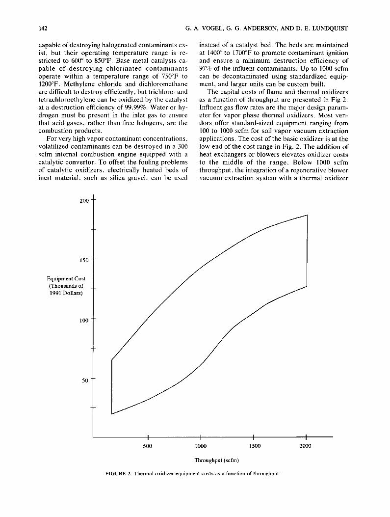
The capital costs of flame and thermal oxidizers as a function of throughput are presented in Fig 2. Influent gas flow rates are the major design param- eter for vapor phase thermal oxidizers. Most ven- dors offer standard-sized equipment ranging from 100 to 1000 scfm for soil vapor vacuum extraction applications. The cost of the basic oxidizer is at the low end of the cost range in Fig. 2. The addition of heat exchangers or blowers elevates oxidizer costs to the middle of the range. Below 1000 scfm throughput, the integration of a regenerative blower vacuum extraction system with a thermal oxidizer
200
150
Equipment Cost (Thousands of 1991 Dollars)
100
50
I I I 500 I000 1500
Throughput (scfm)
FIGURE 2. Thermal oxidizer equipment costs as a function of throughput.
2000

VAPOR PHASE THERMAL OXIDATION 143
raises costs to the top of the range. The addition of instruments and controls can also raise costs by more than $20,000. Operating costs for thermal ox- idizers include fuel costs to maintain combustion chamber or preheat chamber temperature and elec- tricity costs for the pumps, blowers and control sys- tem. Because catalytic oxiders operate at lower temperatures than thermal oxidizers, less fuel is re- quired. However, the lower operating cost of the catalytic oxidizers is somewhat offset by the need to regenerate or replace the catalyst periodically. The maximum life of a catalyst is approximately 3 years, but operating conditions and gas stream con- stituents can shorten catalyst life. Catalyst costs are approximately $5 per pound. Some vendors are willing to rent vapor phase oxidizers.
No distinct guidelines exist for selecting catalytic or flame oxidation units for a specific application. Some published guidelines use contaminant vapor concentration to determine applicability. Concen- trations greater than 30,000 ppmv can be destroyed in an internal combustion engine; concentrations from 1,000 to 10,000 ppmv can be destroyed in flame oxidizers; concentrations from 100 to 5,000 ppmv can be destroyed in catalytic oxidizers; and lower concentrations can be treated using activated carbon or directly discharged. Safety is a major de- sign parameter for vapor phase thermal oxidizers; their operation is governed by insurance require- ments, which are based on National Fire Protection Association (NFPA) standards. NFPA requires au- tomatic shutoff of the oxidizer if influent concentra- tions exceed 50% of the LEL (8,000 ppmv for gas- oline). The installation of continuous LEL monitors is required for operation between 25 and 50% of the LEL, and no monitors are required for opera- tion at less than 25% of the LEL. Most vendors choose to operate at influent contaminant concen- trations less than 25% of the LEL by blending dil- uent air with vapors at higher concentrations. Some states, such as California, either do or will require fume oxidizers to operate at less than 25% of the LEL. Either flame or catalytic oxidizers can oper- ate at concentrations less than 25% of the LEL, making selection dependent on economics and per- sonal preference.
Most vendors sell both flame and catalytic oxi- dizers; a few vendors sell only one type. Several vendors offer flame units with provisions for adding a catalyst bed. Soil gas concentrations can exceed 100% of the LEL when vacuum extraction systems begin remediation. These high concentrations are usually diluted with ambient air and destroyed in flame units. As the contaminant source is depleted by vacuum extraction, concentrations can decrease significantly. Catalysts can be added at that time to
defray the high fuel cost of operating flame units at low influent concentrations. Heat exchangers can be added in the same manner. Air stripper effluent concentrations are typically significantly less than 25% of the LEL, so modification of the mode of oxidizer operation is usually not necessary.
THERMAL OXIDIZER OPERATION
The flow rate of the contaminated vapor determines the oxidizer size. If the initial contaminant concen- tration is high enough to cause the oxidizer to over- heat, dilution air is mixed with the vapor to keep the catalyst bed exit temperature less than 1250°F, or the flame unit less than 1400 to 1500°F. Flow con- trol is most critical during the first few weeks of operation on soil gas vacuum extraction systems when contaminant concentrations can be very high and variable. After the initial operation period, ox- idizers can be left unattended and checked as infre- quently as every week.
Any level of control is available. Ambient air is admitted through a damper that is initially open for startup and then adjusted to maintain operating temperatures. Automatic air control dampers offer more efficient operation; the fuel valve or electric heater for the air preheat chamber can also be con- trolled automatically. Additional process monitor- ing can include the differential pressure across the catalyst bed; flows of contaminated vapor, diluent air, and the combined feed to the oxidizer; and pres- sure in the combustion air blower duct and the va- por feed line. Exhaust gases can be continuously monitored for oxygen and carbon monoxide con- tent. The sumps of knockout pots can be manually drained when full, or level sensors can be installed to automatically operate a drain pump. Disposal of the entrapped liquid is often regulated; some states will not allow its return to the ground.
Natural gas and propane burner feed systems are designed in accordance with insurance and NFPA codes. All units are equipped with high temperature and flame failure interlocks for personnel and equipment protection. As an interesting sidelight, regulators and insurance personnel seem to be at cross purposes with each other; the former want the units to run through upsets, whereas the latter want the units to shut down. Most vendors are capable of providing whatever control system a customer might want, but indicate the simplest units consti- tute the largest sales volume.
Some states, particularly California, Texas, and New Jersey, regulate the operation of thermal oxi- dizers for site remediation. There are no federal reg-

144 G. A. VOGEL, G. G. ANDERSON, AND D. E. LUNDQUIST
ulations governing their operation, and many states do not regulate such small units. The trend in reg- ulations is toward limiting emissions from vacuum extraction systems and air strippers, and oxidizer performance is likely to receive more attention as these regulations are developed. Thermal oxidizer performance is determined by monitoring the influ-
ent vapor composition after any dilution and the exiting stack gas composition to calculate a destruc- tion efficiency for contaminants of concern. Regu- lations require destruction efficiencies ranging from 95 to 98%. The large number of oxidizers operat- ing in California attests to their ability to achieve such performance.
Open for discussion until 26 August 1994.