tech 2 evap service contents bay test re-enabled 2 evap service bay test re-enabled for many years,...
TRANSCRIPT

In automotive terms, a parasitic drain isan electrical load that draws current fromthe battery when the ignition is turned off.Some devices, such as the PCM and radiomemory are intended to draw a very smallamount continuously. These draws are
measured in mil-liamps (mA).
In normal use,parasitic drainsaren’t usually causefor concern,because the batteryis replenished eachtime the vehicle isdriven. But, in long-term parking situa-tions, parasiticdrains may dis-charge the batteryenough to cause ano-start condition.New vehicles indealer stock and air -
port long-term parking are two such situa-tions.
An abnormal parasitic drain could be aglovebox or luggage compartment lightthat remains on but undetected. Or an
electronic component may malfunctionand cause a parasitic drain that is largerthan normal specification.
Parasitic Drains and On-the-Lot Battery Discharge
TIP: In most cases of discharged batter-ies in low-age, low-mileage vehicles, prop-er charging procedures with approvedcharging equipment is the only repair nec-essary.
Here are some rules of thumb thatmight help relate parasitic drains to howlong a battery would last on a parked vehi-cle.
The Reserve Capacity (RC) rating multi-plied by 0.6 gives the approximate avail-able ampere-hours (AH) from full charge tocomplete run-down. Somewhere betweenfull charge and complete rundown, thebattery will reach a point at which it can nolonger start the engine, although it maystill operate some of the electrical acces-sories.
1
Service and Parts Operations
April 2002Volume 4, No. 4
Contents
Dealing with Battery Parasitic Drains . . . . . . . . .1
Tech 2 EVAP Service Bay Test Re-enabled . . . . . .1
Midtronics Micro 411 Battery Tester Update . . . .2
Class 2 Corner . . . . . . . . . . . . . . . . . . . . . . . .2
Diagnostic Strategy Update . . . . . . . . . . . . . . . .3
Rear Fog Lamp Bulb Life . . . . . . . . . . . . . . . . . .3
Theft Deterrent Application and Programming . . .4
Clunk During a Turning Maneuver, part 2 . . . . . . .5
Power Sliding Door Recall Clarification . . . . . . . . .5
Tracker Roof Rack Cross Rail . . . . . . . . . . . . . . .5
Door Glass Sash Panel . . . . . . . . . . . . . . . . . . .5
Avoiding Damage to Steering Column Parts . . . . .5
Repair Order Documentation . . . . . . . . . . . . . . .6
New Transmission Return Form . . . . . . . . . . . . .7
New Information-Only Prompt at TAC . . . . . . . . .7
Bulletins . . . . . . . . . . . . . . . . . . . . . . . . . . . . .8
continued on page 3
Tech 2 EVAP ServiceBay Test Re-enabled
For many years, emission regulationshave required an on-board system to trapfuel vapor from entering the atmosphere.Even a very small leak in the EVAP sys-tem could allow vapors to escape. So, on-board leak detection is an important func-tion of the EVAP system.
Government requirements sometimeschange; this has happened to EVAP regu-lations. Currently, the on-board diagnosticsmust be able to detect a leak as small as0.020-inch (0.51 mm).
The Tech 2 EVAP Service Bay Test isuseful because it can tell the PCM to runthe on-board diagnostic EVAP tests withslightly relaxed cold-start enable criteria.Because a complete cold start is notrequired, EVAP system testing and/orrepair verification runs more quickly,including setting the readiness “flag”used for I/M testing in certain areas of thecountry.
TIP: The J-41413-200 Evaporative
Emission System Tester (“smokemachine”) was described in theNovember 2001 TechLink. It helps locateleaks and confirm repairs. However, it willnot reset the readiness “flag” in the PCM.
It was discovered that the Tech 2 EVAPService Bay Test did not accurately reflectwhat was going on in certain vehiclesequipped with V6 and premium V8engines. So, for a while, the EVAP ServiceBay Test was disabled in Tech 2 softwarefor these vehicles.
Now that the situation has been studiedand better understood, the EVAP ServiceBay Test is being re-enabled for a numberof these vehicles. The Tech 2 softwarecontained on CD 3 for 2002 includes thischange. This programming is also includedin the current TIS 2000 update broadcastthrough the GM ACCESS satellite.
We've covered only the highlights here.This is a somewhat complicated issue, sobe sure to read the upcoming Bulletin 02-06-04-014, which will list those vehi-cles that will remain disabled.
- Thanks to Mark Potter and Steve Abbosh

GM TechLink is a monthly magazinefor all GM retail technicians andservice consultants providing timelyinformation to help increase knowl-edge about GM products andimprove the performance of theservice department. This magazineis a companion to the GM Edgepublication.
Publisher & Editor:
Mark StesneyGM Service Operations/[email protected]
Technical Editor:
Jim Horner/[email protected]
Production Manager:
Marie Meredith
Desktop Publishing:
Greg Szpaichler, MediaWurks/[email protected]
FAX number: 31-248-649-5465
Write to: *TechLinkPO Box 500Troy, MI 48007-0500
GM TechLink on the Web: :http://service.gm.com
General Motors service tips areintended for use by professional tech-nicians, not a "do-it-yourselfer." Theyare written to inform those techni -cians of conditions that may occur onsome vehicles, or to provide informa-tion that could assist in the properservice of a vehicle. Properly trainedtechnicians have the equipment, tools,safety instructions and know-how todo a job properly and safely. If a con-dition is described, do not assumethat the bulletin applies to your vehi-cle or that your vehicle will have thatcondition. See a General Motors deal-er servicing your brand of GeneralMotors vehicle for information onwhether your vehicle may benefit fromthe information.Inclusion in this publication is not nec-essarily an endorsement of the indi-vidual or the company.
Copyright© 2002 General Motors Corporation
All rights reserved.
2
The Class 2 Message Monitor pro-vides two features that allow the Tech 2to send a wake-up message to the con-trollers on the Class 2 bus. They are"Ping" and "Ping All". These modes allowyou to watch the response of a con-troller when the ping message is sent.The difference between Ping and PingAll is simple. If you want to send awake-up message to all controllers onthe bus, press the "Ping All" softkey. Ifyou want to concentrate on just onecontroller, highlight the controller andpress "Ping".
The test is run with the Tech 2 in
Class 2 Message Monitor mode withthe ignition off, so all the controllers areshowing Inactive. After pinging, thecontroller should respond by becoming"Active" for a short time, then return toInactive, assuming no other inputs suchas ignition-on are received.
TIP: Not all controllers will respond tothe "Ping" command. It will be neces-sary to try this on a known-good vehicleto determine the correct response fromthe controllers before you can make anyconclusions about a suspect controlleron the vehicle being worked on.
– Thanks to Mark Harris
Midtronics Micro 411 BatteryTester Update
The J-42000 Midtronics Micro 410 bat-tery tester was introduced in 1998. Itprovides a convenient alternative to thetraditional battery load test and is alsocapable of testing batteries with a lowstate of charge.
A revised Micro 411 tester, the J-42000-EU, is now being released as arunning change.
Features of the New J-42000-EU
The software in the new J-42000-EUhas a built-in AGM prompt. This elimi-nates the need to add 100 to the bat-tery’s CCA when testing AGM (absorbentglass mat) batteries, as required by theoriginal tester.
Another software difference is noticedwhen performing an in-vehicle test. If thebattery tests “good,” the diagnostic codeappears. But if a “replace battery” read-out appears, you must first run an out-of-vehicle test before the diagnostic code isdisplayed.
The J-42000-EU is equipped with aninfrared port, which transmits data to anoptional cordless thermal printer,J-42000-20. The printout includes the lastfour digits of the VIN, and may be
attached to the repair order as additionaldocumentation of the diagnostic codeand the battery’s test condition. You mayalso want to provide a copy to the cus-tomer.
If you purchase the new tester and theoptional printer, they are packaged in aconvenient plastic storage case.
The new J-42000-EU will replace theoriginal model in the Kent-Moore catalog,so if you purchase a new one, it will havethe updated features.
Tips for Using the J-42000-EU TesterEffectively
When using the J-42000-EU (or theoriginal J-42000), be sure to get goodconnections at the battery. In the vehicle,make sure the battery terminals andcables are clean and tight.
Make sure both jaws of each testclamp are making good connection. Eachjaw is wired to a different part of thetester and both are essential.
Be sure the ignition and all accessoriesare turned off.
TIP: When using the original J-42000only , you must add 100 to the battery’sposted CCA rating if you are testing anAGM battery (August 2000 TechLink),. Aspecial tag with this information wassent out to be attached to your J-42000.
Before condemning a battery as bad,always perform an out-of-vehicle testwith the battery terminal adaptors prop-erly attached to the battery. Using boltsor unapproved adaptors can lead to fail-ing batteries that are not defective.
TIP: The GM p/n 12303040 terminaladaptor is the ONLY acceptable substi-tute to the one that comes with thetester.
Record the test code on the repairorder. This is necessary for continuingproduct improvement.
- Thanks to Dave Roland and Charley Gipe

Using up about 40% of the total avail-able AH will usually take a fully-chargedbattery to a no-start condition at moderatetemperatures of 77°F (25°C). Put anotherway, for a typical battery in a storage situa-tion, depleting the available AH by 20 to30 AH will result in a no-start condition.
TIP: If the battery begins storage at90% of full charge, reduce the availableAH accordingly.
The recommendation for maximum par-asitic drain is around 30 mA (0.030 amps).A typical drain today actually falls into the7 - 12 mA range, even though some vehi-cles do approach the maximum. Multiplythe drain (in amps) by the time (in hours)the battery sits without being recharged.The result is the amount of AH consumedby the parasitic drain. The actual drain maybe small, but over time the battery growssteadily weaker.
Here’s an example. A vehicle with a 30mA drain and a fully-charged 70 RC batterywill last 23 days. But if that battery is atonly 65% of full charge (green dot barelyvisible), it is going to last only 15 daysbefore causing a no-start.
The Effects of Temperatureon a Standing Battery
The parasitic drain will be fairly constantover a range of temperatures. The impor-tant temperature is that of the vehicle atthe time a start is attempted. Colder tem-perature raises the threshold of a no-startby increasing the residual power needed.When the temperature falls to 32°F (0°C),the battery will be able to put out onlyabout 85% of its normally-available startingpower, and the engine may need as muchas 165% of the usual power to start.
The combined effect of these two fac-tors is to reduce the number of days thebattery can stand with a parasitic drain. At32°F (0°C), the battery can stand only halfas long as it could at 77°F (25°C). And at0°F (-19°C), the standing days are reducedto one-fourth.
Temperatures above a moderate climateof 77°F (25°C) increase the battery's inter-nal self discharge. If the battery is in alocale where the temperature is averaging90°F (32°C), an additional 5% to 10% ofthe available ampere-hours will be lost in amonth due to self-discharge within thebattery. At temperatures below the moder-ate range, self discharge will be lowenough to be negligible compared to theparasitic loss.
What the Policies andProcedures Manual SaysAbout Parasitic Drains
Because determining how long a batterymay last in a storage situation is not pre-cise, the P&P manual provides a clearcutpolicy, excerpted here.
“Discharged batteries can freeze attemperatures as high as 32°F (0°C), caus-ing permanent damage. Other permanentdamage may result from allowing batteriesto stand discharged for extended periods.
“To alleviate this condition, the negativebattery cable should be disconnected onvehicles which are not going to be in ser-vice within a 20 day period, beginningfrom the time the vehicle is shipped. Ifthis is not possible, batteries should berecharged periodically, every 20-45 days,until the green eye is visible.
“Disconnected batteries will slowly dis -charge, especially with higher tempera -tures; therefore, even disconnected batter -ies should be checked for a green eyeevery four months and recharged if neces-sary.
“Vehicles on display are subject to bat-tery discharge due to drains from courtesylights and other accessories. Provision tomaintain battery state of charge for thesevehicles will be necessary.”
Consult your P&P manual for full details.
Tracking Down the Sourceof a Parasitic Load
If the battery in a vehicle becomes dis-charged in a shorter time than describedearlier, the vehicle may have an out-of-specification parasitic load. SI 2000 con-tains procedures for locating parasiticloads. Here’s the path.
- Build the vehicle
- Engine
- Engine Electrical
- Diagnostic Information and Procedures
- Battery Electrical Drain/Parasitic LoadTest
You will need the J-38758 ParasiticDraw Test Switch and a digital multimeterset to the 10A scale.
TIP: Read the procedure and follow thesteps exactly as described in SI 2000. Thefollowing is a summary, not the completeprocedure.
The test switch permits you to place anammeter in series with the battery nega-tive cable. Before performing the test, the
engine must be run and all accessoriesmust be operated as instructed. Aftershutting the ignition off, turn the testswitch off. Now, all current being used bythe vehicle is shunted through the amme-ter where it is measured. If the reading isout of specification, the procedureexplains how to pinpoint the cause.
Finally, a Word AboutBattery Testing
Your dealership has an essential tool,Midtronics Micro 410 Battery Tester J-42000. Use it to quickly identify batteriesthat are serviceable and can be charged.There is information about this tool in bul-letin 99-06-03-012. There was an articleabout this tester in the May 2000 issue ofTechLink, and there’s an update on page 2of this issue, covering the newly-revisedMicro 411 tester J-42000-EU.
- Thanks to Rick Overman and Dave King
3
DiagnosticStrategy Update
Many technicians have wonderedif the diagnostic strategy articleprinted in the February issue ofTechLink is replacing the tried andtrue Strategy Based Diagnostics.
No. Strategy Based Diagnosticshas not been replaced.
The focus of the February articlewas to add clarity to how a techni-cian should navigate through thediagnostic starting point and systemcheck when they begin step 3(Perform Published DiagnosticSystem Checks) of Strategy BasedDiagnostics. We apologize for anyconfusion generated by the omis-sion of this information.
- Thanks to Mark Haning and JohnBowman
Rear Fog Lamp Bulb Life
Some customers who leave therear fog lamps on all the time, on a2001-2002 Oldsmobile Aurora, maycomment that the bulb life appearss h o rt. A Sylvania 921LL extendedlife bulb is available from GMSPO.The GM part number is 22692679.
- Thanks to Ian Doran

4
Theft DeterrentApplication andProgramming
This chart shows which theft deterrentsystem is used in which vehicle. At thebottom of the chart is the legend of theftdeterrent system types.
Some theft deterrent system compo-nents need to be programmed whenreplaced. The programming proceduresare in service manual subsection TheftDeterrent.
When diagnosing the Vehicle TheftDeterrent system on a 1998-99 vehicle,refer to the Instrument Panel, Gaugesand Console service manual section. For2000 and beyond, refer to the TheftDeterrent service manual section.TIP: Use SI 2000 for 1998-2003 vehiclesto avoid having to search for servicemanual update bulletins.
Opel Immobilizer - Theft deterrentcontrol module, keys, ignition lock cylin-der, engine control module
Passlock - Ignition lock cylinder, bodycontrol module, powertrain control module
Passkey II, VATS, PASS-Key - IPCreplacement requires Engine ControlModule programming. 1997-2002Corvette - body control module, enginecontrol module
Passkey III - Theft deterrent controlmodule, keys, powertrain control module
Passkey III+ - Theft deterrent controlmodule, keys, powertrain control module
- Thanks to Jerry Garfield, Brent Drendall,Dave Nowak and Lance Mossman(Applegate Chevrolet)
5
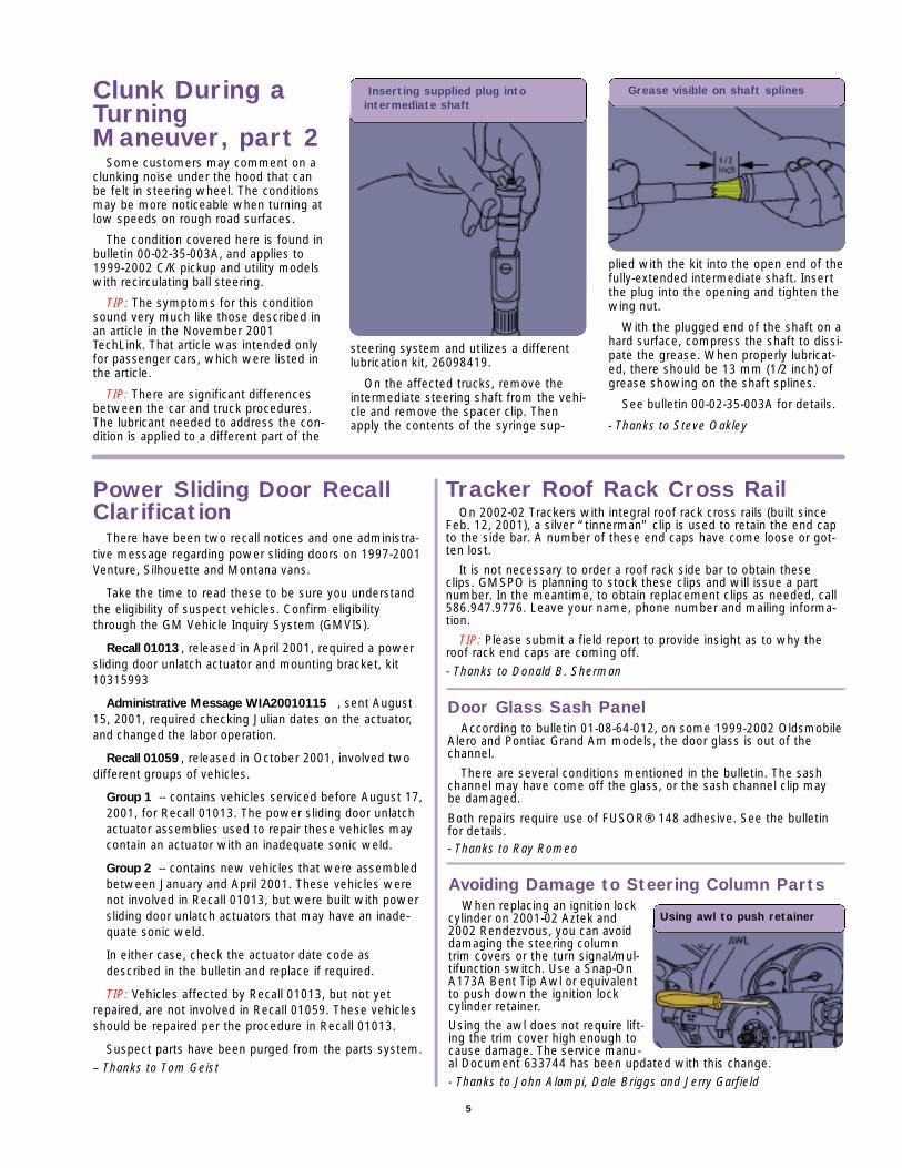
Clunk During aTurningManeuver, part 2
Some customers may comment on aclunking noise under the hood that canbe felt in steering wheel. The conditionsmay be more noticeable when turning atlow speeds on rough road surfaces.
The condition covered here is found inbulletin 00-02-35-003A, and applies to1999-2002 C/K pickup and utility modelswith recirculating ball steering.
TIP: The symptoms for this conditionsound very much like those described inan article in the November 2001TechLink. That article was intended onlyfor passenger cars, which were listed inthe article.
TIP: There are significant differencesbetween the car and truck procedures.The lubricant needed to address the con-dition is applied to a different part of the
steering system and utilizes a differentlubrication kit, 26098419.
On the affected trucks, remove theintermediate steering shaft from the vehi-cle and remove the spacer clip. Thenapply the contents of the syringe sup-
plied with the kit into the open end of thefully-extended intermediate shaft. Insertthe plug into the opening and tighten thewing nut.
With the plugged end of the shaft on ahard surface, compress the shaft to dissi-pate the grease. When properly lubricat-ed, there should be 13 mm (1/2 inch) ofgrease showing on the shaft splines.
See bulletin 00-02-35-003A for details.
- Thanks to Steve Oakley
Inserting supplied plug intointermediate shaft
Grease visible on shaft splines
Power Sliding Door RecallClarification
There have been two recall notices and one administra-tive message regarding power sliding doors on 1997-2001Venture, Silhouette and Montana vans.
Take the time to read these to be sure you understandthe eligibility of suspect vehicles. Confirm eligibilitythrough the GM Vehicle Inquiry System (GMVIS).
Recall 01013 , released in April 2001, required a powersliding door unlatch actuator and mounting bracket, kit10315993
Administrative Message WIA20010115 , sent August15, 2001, required checking Julian dates on the actuator,and changed the labor operation.
Recall 01059 , released in October 2001, involved twodifferent groups of vehicles.
Group 1 -- contains vehicles serviced before August 17,2001, for Recall 01013. The power sliding door unlatchactuator assemblies used to repair these vehicles maycontain an actuator with an inadequate sonic weld.
Group 2 -- contains new vehicles that were assembledbetween January and April 2001. These vehicles werenot involved in Recall 01013, but were built with powersliding door unlatch actuators that may have an inade-quate sonic weld.
In either case, check the actuator date code asdescribed in the bulletin and replace if required.
TIP: Vehicles affected by Recall 01013, but not yetrepaired, are not involved in Recall 01059. These vehiclesshould be repaired per the procedure in Recall 01013.
Suspect parts have been purged from the parts system.
– Thanks to Tom Geist
Tracker Roof Rack Cross RailOn 2002-02 Trackers with integral roof rack cross rails (built since
Feb. 12, 2001), a silver “tinnerman” clip is used to retain the end capto the side bar. A number of these end caps have come loose or got-ten lost.
It is not necessary to order a roof rack side bar to obtain theseclips. GMSPO is planning to stock these clips and will issue a partnumber. In the meantime, to obtain replacement clips as needed, call586.947.9776. Leave your name, phone number and mailing informa-tion.
TIP: Please submit a field report to provide insight as to why theroof rack end caps are coming off.
- Thanks to Donald B. Sherman
Avoiding Damage to Steering Column PartsWhen replacing an ignition lock
cylinder on 2001-02 Aztek and2002 Rendezvous, you can avoiddamaging the steering columntrim covers or the turn signal/mul-tifunction switch. Use a Snap-OnA173A Bent Tip Awl or equivalentto push down the ignition lockcylinder retainer.
Using the awl does not require lift-ing the trim cover high enough tocause damage. The service manu-al Document 633744 has been updated with this change.
- Thanks to John Alampi, Dale Briggs and Jerry Garfield
Using awl to push retainer
Door Glass Sash PanelAccording to bulletin 01-08-64-012, on some 1999-2002 Oldsmobile
Alero and Pontiac Grand Am models, the door glass is out of thechannel.
There are several conditions mentioned in the bulletin. The sashchannel may have come off the glass, or the sash channel clip maybe damaged.
Both repairs require use of FUSOR® 148 adhesive. See the bulletinfor details.- Thanks to Ray Romeo

6
The Case of the Juicy SteakOr, Why Repair OrderDocumentation Is SoImportant
The waiter sets the strip steak infront of you. Juicy, mouth-watering,medium rare. “But,” you say, “Iordered pot roast.” A few minuteslater, the waiter returns with anotherstrip steak, broiled to perfection, siz-zling mushrooms on the side.
What’s going on here? First, thewaiter didn’t write down your orderclearly. Then when you sent the steakback, he just told the chef that youwere unhappy with your food. Notknowing the nature of the problem, thechef cooked up another strip steak andthis time added some mushrooms.Problem solved? Not even close.
So, what’s the point? Repair orderdocumentation.
A detailed description of the condi-tion that caused the customer to bringthe vehicle in, the cause, and the cor-rection (the three Cs) are important ele-ments.
First, here’s how you’ll benefit. Aclearly worded statement of the condi-tion helps you quickly and accuratelyresolve the customer’s concerns. Andthat’s good for minimizing comebacksand improving CSI. And clear and com-plete statements of cause and correc-tion are needed for making warrantyclaims and supporting claims reviews.
Second, the same information is crit-ical to the GM engineers and BrandQuality managers who review returnedparts with the parts suppliers at theWarranty Parts Return Center. Theywant to get to the root cause of whythe part had to be replaced so the con-dition can be quickly resolved. Theyexamine the returned parts and per-form detailed tests to find out why thepart was replaced, why it failed to per-form. The most important documentthey rely on is the repair order yousend back with the part.
Sometimes the sample size is quitesmall, only a half dozen parts or so. Iftwo or three of the repair orders con-tain incomplete information, the sam-ple size may be cut in half. This greatlyreduces the effectiveness of the analy-sis process.
The First C -- Condition
It all begins with the service consul-tant. Here are some tips obtained fromthe GM Retail Operating System website,at http://gmweb.siweb.com/gmros(on GM infoNET in Canada).
Listen carefully to the customer’sdescription of the condition. Ask open-ended questions to prompt as muchinformation as possible about the con-dition from the customer.
Paraphrase the customer’s wordsback to make sure you understandwhat was said. Then clearly documentthe customer’s observations about thecondition on the repair order exactly asstated. Do not interpret. The technicianneeds to know the problem from the
customer’s standpoint. If necessary,attach a separate note to the repairorder to capture this information.
The Second and Third C -- Causeand Correction
The second and third steps are theresponsibility of the technician. Butequally important to finding the causeand making the correction is the doc-umentation of what went on duringthe diagnosis and repair. Detailedinformation at this point helps GMengineers identify and resolve prod-uct problems faster:
- Diagnostic trouble codes
- Test results
- Circuit numbers
- Descriptive locations
- Relevant observations
Some Examples
Refer to bulletin 00-00-89-015A. Itcontains poor and good examples ofdescriptions of condition, cause andcorrection from nearly two dozen repairorders.
Two samples are shown below.
In the future, when you’re filling outa repair order -- whether you’re a ser-vice consultant or technician -- take afew extra moments to write down thedetails. It really can make a difference.
Without your help, the “pot roast”may keep on coming out “steak.”
- Thanks to Keith McKenzie and GarySmits
Poor Example Good Example
Condition: Can't open tailgate Condition: Customer states tailgate will not open
Cause: Handle broken Cause: T-gate handle stress cracked at pivot arms
Correction: Replace handle Correction: Replaced T-gate handle and bezel
Poor Example Good Example
Condition: Noise in rear Condition: Loud growling noise in rear endover 20 mph (32 km/h)
Cause: Bearing bad Cause: Pinion bearing failure - high preload turningtorque 40 lb in (4.5 N·m)
Correction: Replace all rear Correction: Replaced rear differential pinionend bearings and side bearings

7
New TransmissionReturn Form
The accompanying article on repairorder documentation applies to trans-missions as well. But in the case ofcomponents that must be returned asa core for possible remanufacturing,there are several additional concerns.
One of these is the product feed-back form, which must accompany alltransmission returns when a servicereplacement has been installed. This isdetailed in Bulletin 01-07-30-029. In thepast, the feedback form was to beinserted into an envelope and wired tothe transmission inside the return ship -ping carton.
The new form, shown in the photo,is to be inserted into the suppliedtransparent envelope and attached tothe outside of the shipping carton.
When cores arrive at the partsreception center, they are inspected fordamage, missing parts, and other fac-tors that would affect remanufacturing.Now, the absence of a feedback formis going to be treated as a missingpart. The parts department will receivea reminder message. And a summaryof missing feedback forms will be sentto each region, organized by dealer ID.
You can avoid this inconvenience bysimply filling out the feedback form inits entirety and attaching it to the trans-mission carton. Be sure to explain indetail why the transmission wasreplaced. Engineering will then use thisinformation in performing a root-causeanalysis. As explained in the accompa-nying article, this data is valuable inensuring ongoing product improve-ment.
Additional forms (PN 24221234) andenvelopes (PN 2XJ19572) can ordereddirect from GM Dealer World Delivery.Phone 1.866.700-0001, fax 1.313.957.5555, or email [email protected].
- Thanks to Bob Martin
New Information-Only Prompt atTechnicalAssistance
The General Motors TechnicalAssistance Center (TAC) has implement-ed an information-only prompt that youcan access for quick questions that donot require diagnostic assistance.Messages have been sent by DCS andVME Express explaining the new informa-tion-only prompt. This article is meant tosupport those communications as well asanswer questions that have come uprelated to this new service.
When calling TAC and choosing theInformation-Only prompt, you will speakto the same consultants you always have.They will still verify your dealer code andyour name as an authorized caller. Theywill then move straight to the reason foryour call. The TAC consultant will supplyyou with the information requested, if it isavailable. A TAC case may not berequired on these calls, although informa-tion related to the vehicle may be neces-sary for verification purposes.
The Diagnostic Assistance prompt willbe the same as before. The consultantwill require information related to thevehicle, strategy-based diagnostics andrepair history. They will create a TAC caseand request a follow up in the form of acall-back for additional assistance or acase closing by VME or Fax.
Everyone's perception of Information-Only could be different and this changewill require the use of common senseand good judgement at both ends of thephone. Outlined below are some basiccriteria for both types of calls as wellalternate phone numbers for informationthat TAC is not able to supply.
When to use Information-Only Prompt:
- PI Information
- TSB Information or Clarification
- Campaign Information or Clarification
When to use Diagnostic AssistancePrompt:
- Previous repair attempts made for same concern
- Customer is seeking repurchase of the vehicle
- A TAC case already exists
- Whenever there is doubt which prompt to choose
Information TAC is not able to provide:
- Warranty Information or Authorization
Contact the Dealer Business Center at 1.888.414.6322
- Parts Concerns
Contact ParTech at 1.800.433.6961
- Problems with Techline Equipment orTIS 2000
Contact Techline Customer SupportCenter at 1.800.828.6860
- Questions Regarding Service Guild Tests
Contact Program Headquarters at 1.800.610.5669
Here are some commonly asked ques-tions and answers related to theInformation-Only prompt.
Q. Can I give customers the phonenumber to GM TAC so they can call inwith Information-Only type questions?
A. No, the TAC is not equipped tohandle inquiries directly from cus-tomers. Only dealer service personnelare authorized to call TAC.
Q. If I call in on the Information-Onlyprompt, will I speak with the samepeople that answer the Diagnosticcalls?
A. Yes, The same consultants handlethe Information and the Diagnosticprompts. For example, consultantswho handle Steering calls will handleSteering Info and Steering Diagnostic.
Q. Is it possible to still receive a GMTAC case number when calling theInformation-Only prompt?
A. Yes, an information-only call couldturn into a diagnostic assistance typecall, where a TAC case would be thebest thing for you.
Q. Do I need to have the repair orderhandy when I call the Information-Onlyprompt?
A. Yes, the TAC consultant will needto verify that the information providedmatches the type of vehicle you areworking on.
Q. If I already have a GM TAC casenumber and I’m calling back for furtherassistance, which prompt should Iuse?
A. The Diagnostic Prompt. - Thanks to GM Technical Assistance

8
Bulletins - March 2002
This review of service bulletins releasedthrough mid-March lists the bulletin num-ber, superseded bulletin number (if applica-ble), subject and models.
GENERAL INFORMATION:
99-00-89-019B; replaces 99-00-89-019;Warranty Parts Center/Corporate PartsReturn Program; 2002 and PriorPassenger Cars and Trucks
HVAC:
01-01-39-005A; replaces 01-01-39-005;Noise or Vibration in PassengerCompartment with A/C On Between2000-2400 RPM (Replace Heater OutletHose); 2001-02 Chevrolet and GMC C/KPickup Models with 4.3L V6 Engine (VINW -- RPO L35) and Air Conditioning (RPOC60)
SUSPENSION:
01-03-08-003A; replaces 01-03-08-003; Squawk Noise from Front and/orRear Suspension (Lubricate StabilizerBushings); 1997-2002 Chevrolet Malibu,Oldsmobile Cutlass, Alero, Pontiac GrandAm
01-03-10-008A; replaces 01-03-10-008; False Tire Inflation Monitor System(TIM) Message/Lamp Illumination (InstallNew Electronic Brake Traction ControlModule - (EBTCM); 1999-2001 BuickCentury, Regal, 2000-01 ChevroletImpala, Monte Carlo
02-03-08-002; Front of Vehicle SitsToo Low, Bottoms Out Over Bumps(Replace Front Coil Springs,Inspect/Replace Frame and Mount);2000-01 Chevrolet Impala with RPO 9C1Police Car and 9C3 SEO Vehicle PoliceCar, Limited Content
02-03-08-003; Revised FrontSuspension Fastener TighteningSpecifications; 2000-02 Chevrolet Malibu,Oldsmobile Alero, Pontiac Grand Am
02-03-10-001; Spare Tire is DifferentSize Than Other Tires; 2001-02 GMCSierra C3, GMC C/K Utility Models, GMCSierra Denali, Cadillac Escalade, EXT
DRIVELINE AXLE:
02-04-17-001; LaunchShudder/Vibration on Acceleration(Replace Propeller Shaft and Install NewPinion Flange/Seal); 1999-2002 Chevroletand GMC C1500 Series Extended CabModels with 4L60-E Auto Trans (RPOM30)
02-04-21-002; “Service 4WD”Indicator Illuminated, DTC B2725 Set(Replace Transfer Case Shift Control
Switch); 2002 Chevrolet and GMC S/TUtility Models with Four Wheel Drive
BRAKES:
01-05-23-011A; replaces 01-05-23-011; Rattle Type Noise Coming FromFront of Vehicle (Install Front CaliperService Kit); 2000-01 Buick Century,Regal, Chevrolet Impala, Monte Carlo,Venture, Oldsmobile Intrigue, Silhouette,Pontiac Grand Am, Montana
ENGINE/PROPULSION SYSTEM:
00-06-04-010A; replaces 00-06-04-010;New Product Information -- OxygenSensor Usage and Diagnostics; 2000Chevrolet and GMC C/K Models with7.4L Engine (VIN J -- RPO L29)
02-06-01-006; Correct Amount ofEngine Oil Needed to Raise Level FromLow Mark to Full mark on Dipstick; 1999-2002 Chevrolet Tracker
02-06-04-002; CommunicationInformation Irregularities When UsingGeneric Scan Tools (Reprogram PCM);2001 Chevrolet and GMC C/K PickupModels with 6.6L Duramax™ DieselEngine (VIN 1 -- RPO LB7)
02-06-04-003; Auxiliary Fuel TankRemoval Procedure; 2001-02 Chevroletand GMC C/K 3600 Chassis Cab Models
02-06-04-005; Revised DTC P1221;specified 2001-02 vehicles with 4.8L,5.3L, 5.7L, 6.0L or 8.1L Engine (VINs V, T,G, S, U -- RPOs LR4, LM7, LS1, LS6,LQ4, L18)
02-06-04-006; SES Lamp On, MILIlluminates Intermittently, DTC Set,Blown Fuses, Engine Will Not Start(Repair Wires); 1997-2002 Chevrolet andGMC F Model MD Tilt Cab with Isuzu7.8L Diesel Engine (VIN 3 -- RPO LG4) orCaterpillar 3126 Diesel Engine (VIN C --RPO LG5)
TRANSMISSION/TRANSAXLE:
00-07-30-007A; replaces 00-07-30-007; Whine Noise in Park or Neutral, SESor SVS Lamp Illuminates (Replace DriveSprocket Support Bearing); specified1999-2000 vehicles with 3.4L or 3.8LEngine and Hydra-Matic 4T65-E Trans(RPOs MN3, MN7, M15)
02-07-29-001; Grinding/Rattle TypeNoise Coming from Transmission(Diagnose and Perform Repair); 2000-02Chevrolet Cavalier, Pontiac Sunfire, 2001-02 Oldsmobile Alero, Pontiac Grand Amwith Manual Transmission (RPO M86 orM94)
02-07-30-007; “AT Oil Temp” Light
On, DTC 15 Set (Adjust Auto Trans Fluidto Correct Level); 1999-2002 Chevroletand GMC W Series MD Tilt Cab Modelswith Diesel Engine and AISIN Auto Trans
BODY AND ACCESSORIES:
01-08-45-006A; replaces 01-08-45-006;Availability of New Micro 64 ElectricalTerminals for Wiring Repairs; 2002Cadillac Seville, Chevrolet Cavalier,Oldsmobile Alero, Pontiac Grand Am,Sunfire
01-08-66-011B; replaces 01-08-66-011A; Rear Roof Perforation (Install NewRear Roof Section); 1995-2001 Chevroletand GMC S/T 2-Door and 4-Door UtilityModels, 1996-2001 Oldsmobile Bravada
02-08-44-002; Clarion Radio ExchangeProgram and Audio SystemTroubleshooting; specified 1995-2002 MDTrucks
02-08-45-001; Dome Lamp, DaytimeRunning Lamps and/or Dome Lamp TimeDelay Inoperative (Repair Connection atG200); 1999-2002 Chevrolet Tracker
02-08-49-001; Revised Fuel GageInaccurate or Inoperative DiagnosticProcedure; 1999-2000 Chevrolet Malibu,Oldsmobile Cutlass
02-08-51-001; Painting of Cladding;2002 Chevrolet Avalanche
02-08-56-001; Revised Pass-Key III®Relearn Procedure; specified 1997-2000passenger cars
02-08-57-002; Rear Floor Carpet Wet(Install Close Tolerance Rubber); 2002Chevrolet Avalanche, Cadillac EscaladeEXT
02-08-66-001; Cargo Cover Seal PullsOff (Clean and Apply Sealer toWeatherstrip); 2002 Chevrolet Avalanche,Cadillac Escalade EXT
02-08-67-001; Headliner Sags atSunroof Opening (Reattach Velcro®Strips)’ 2002-01 Chevrolet Impala
02-08-68-001; Normal OperatingCharacteristics of Cruise Control System;1999-2002 Chevrolet Tracker
02-08-111-001; Paint Wear Through atFifth Bow (Replace Seal); 1998-2001Chevrolet Corvette
02-08-116-001; IntermittentCommunication or Serial Data DTCCodes Stored in Memory; 1997-2002Chevrolet Malibu, Oldsmobile Alero,Cutlass, Pontiac Grand Am with 3.1L or3.4L Engine (VINs J, M, E -- RPOs LG8,L82, LA1)