tdrv002-sw-42 - tews support website in...
TRANSCRIPT

The Embedded I/O Company
TDRV002-SVxWorks Device
Multiple Channel Seria
Version 2.1.x
User Manu
Issue 2.1.0
April 2010
TEWS TECHNOLOGIES G
Am Bahnhof 7 25469 Ha
Phone: +49 (0) 4101 4058 0 Fax: +49 (
e-mail: [email protected] www.tews
W-42Driver
l Interface
al
mbH
lstenbek, Germany
0) 4101 4058 19
.com

TDRV002-SW-42 – VxWorks Device Driver Page 2 of 47
TDRV002-SW-42
VxWorks Device Driver
Multiple Channel Serial Interface
Supported Modules:TPMC371TPMC372TPMC375TPMC376TPMC460TPMC461TPMC462TPMC463TPMC465TPMC466TPMC467TCP460TCP461TCP462TCP463TCP465TCP466TCP467
This document contains information, which isproprietary to TEWS TECHNOLOGIES GmbH. Anyreproduction without written permission is forbidden.
TEWS TECHNOLOGIES GmbH has made anyeffort to ensure that this manual is accurate andcomplete. However TEWS TECHNOLOGIES GmbHreserves the right to change the product describedin this document at any time without notice.
TEWS TECHNOLOGIES GmbH is not liable for anydamage arising out of the application or use of thedevice described herein.
2004-2010 by TEWS TECHNOLOGIES GmbH
Issue Description Date
1.0 First Issue (TPMC461-SW-42) July 14, 2004
1.1.0 Driver Name changed to TDRV002 January 18, 2005
1.2.0 Local Loopback Mode and Selftest added February 28, 2005
1.2.1 File list changed April 1, 2005
1.3.0 Support for programmable interfaces / modules added,tdrv002DevCreate() parameters changed,new ioctl() function FIOSETINTERFACE
September 28, 2005
1.4.0 TPMC467/TCP467 Support added,correction in description of tdrv002DevCreate()
Distribution file list changed
Missing description of error codes addedIntroduction / Installation updated
July 20, 2006
1.4.1 New Address TEWS LLC October 9, 2006
1.4.2 Address TEWS LLC removed November 18, 2009
2.0.0 VxBus Driver Support added January 19, 2010
2.0.1 Configuration Hint added, additional information for self test execution February 18, 2010
2.0.2 Legacy vs. VxBus Driver modified March 25, 2010
2.1.0 New debug function tdrv002Show for VxBus support April 26, 2010

TDRV002-SW-42 – VxWorks Device Driver Page 3 of 47
Table of Contents
1 INTRODUCTION......................................................................................................... 4
2 INSTALLATION.......................................................................................................... 6
2.1 Legacy vs. VxBus Driver ................................................................................................................7
2.2 VxBus Driver Installation ...............................................................................................................7
2.2.1 Direct BSP Builds.................................................................................................................82.2.2 Modification of the ‘Number of serial ports’..........................................................................8
2.3 Legacy Driver Installation ..............................................................................................................9
2.3.1 Include device driver in Tornado IDE project .......................................................................92.3.2 Special installation for Intel x86 based targets ....................................................................92.3.3 System resource requirement ............................................................................................10
3 VXBUS DRIVER SUPPORT..................................................................................... 11
3.1 Assignment of Port Names ..........................................................................................................11
3.2 VxBus Error Codes .......................................................................................................................12
3.3 Default Configuration ...................................................................................................................12
3.4 Compatibility to pre-VxBus applications....................................................................................12
4 LEGACY I/O SYSTEM FUNCTIONS........................................................................ 13
4.1 tdrv002Drv() ...................................................................................................................................13
4.2 tdrv002DevCreate() .......................................................................................................................15
4.3 tdrv002PciInit() ..............................................................................................................................21
5 BASIC I/O FUNCTIONS ........................................................................................... 22
5.1 open() .............................................................................................................................................22
5.2 close().............................................................................................................................................24
5.3 read() ..............................................................................................................................................26
5.4 write() .............................................................................................................................................28
5.5 ioctl() ..............................................................................................................................................30
5.5.1 FIOBAUDRATE..................................................................................................................325.5.2 FIODATABITS....................................................................................................................335.5.3 FIOSTOPBITS ...................................................................................................................345.5.4 FIOPARITY ........................................................................................................................355.5.5 FIOHWHS ..........................................................................................................................365.5.6 FIOSETBREAK ..................................................................................................................375.5.7 FIORECONFIGURE...........................................................................................................385.5.8 FIOSTATUS .......................................................................................................................395.5.9 FIOLOCALLOOP ...............................................................................................................405.5.10 FIOLOCALSELFTEST...................................................................................................415.5.11 FIOSETINTERFACE .....................................................................................................44
6 APPENDIX................................................................................................................ 46
6.1 Debugging Driver Start-Up in VxBus-Systems ..........................................................................46
6.2 Example Application Adaptation.................................................................................................46
6.3 Additional Error Codes.................................................................................................................47
TDRV002-SW-42 – VxWorks Device Driver Page 4 of 47
1 IntroductionThe TDRV002-SW-42 VxWorks device driver software allows the operation of the supported modulesconforming to the VxWorks I/O system specification. This includes a device-independent basic I/Ointerface with open(), close(), read(), write(), and ioctl() functions and a buffered I/O interface (fopen(),fclose(), fprintf(), fscanf(), ...).
Special I/O operation that do not fit to the standard I/O calls will be performed by calling the ioctl()function with a specific function code and an optional function dependent argument.
The TDRV002-SW-42 release contains independent driver sources for the old legacy (pre-VxBus) andthe new VxBus-enabled driver model. The VxBus-enabled driver is recommended for newdevelopments with later VxWorks 6.x release and mandatory for VxWorks SMP systems.
The TDRV002 driver includes the following functions supported by the VxWorks tty driver supportlibrary for pre-VxBus systems or the sio driver library for VxBus compatible systems.
ring buffering of input and output raw mode optional line mode with backspace and line-delete functions optional processing of X-on/X-off optional RETURN/LINEFEED conversion optional echoing of input characters optional stripping of the parity bit from 8 bit input optional special characters for shell abort and system restart
Additionally the following functions are supported (if the channel supports this function):
select FIFO triggering point use 5...8 bit data words use 1, 1.5 or 2 stop bits optional even or odd parity enable/disable hardware handshake (only in FIFO mode) changing Baud Rates enabling/disabling local loopback mode local self-test changing I/O interface (only programmable interfaces)
The TDRV002-SW-42 supports the modules listed below:
TPMC371 8 Channel Serial Interface
TPMC372 4 Channel Serial Interface
TPMC375 8 Channel Serial Interface (programmable Interfaces)
TPMC376 4 Channel Serial Interface (programmable Interfaces)
TPMC460 16 Channel Serial Interface
TPMC461 8 Channel Serial Interface
TPMC462 4 Channel Serial Interface
TPMC463 4 Channel Serial Interface
continued …
TDRV002-SW-42 – VxWorks Device Driver Page 5 of 47
TPMC465 8 Channel Serial Interface (programmable Interfaces)
TPMC466 4 Channel Serial Interface (programmable Interfaces)
TPMC467 4 Channel Serial Interface (programmable Interfaces)
TCP460 16 Channel Serial Interface
TCP461 8 Channel Serial Interface
TCP462 4 Channel Serial Interface
TCP463 4 Channel Serial Interface
TCP465 8 Channel Serial Interface (programmable Interfaces)
TCP466 4 Channel Serial Interface (programmable Interfaces)
TCP467 4 Channel Serial Interface (programmable Interfaces)
In this document all supported modules and devices will be called TDRV002. Specials for acertain devices will be advised.
To get more information about the features and use of supported devices it is recommended to readthe manuals listed below.
User manual of the used module
Engineering Manual of the used module
VxWorks Programmer’s Guide: I/O System – Serial I/O devices
Kernel Programmer’s Guide: I/O System – Serial I/O devices
TDRV002-SW-42 – VxWorks Device Driver Page 6 of 47
2 InstallationFollowing files are located on the distribution media:
Directory path ‘TDRV002-SW-42”:
TDRV002-SW-42-2.1.0.pdf PDF copy of this manualTDRV002-SW-42-VXBUS.zip Zip compressed archive with VxBus driver sourcesTDRV002-SW-42-LEGACY.zip Zip compressed archive with legacy driver sourcesChangeLog.txt Release historyRelease.txt Release information
The archive TDRV002-SW-42-VXBUS.zip contains the following files and directories:
Directory path ‘./tews/tdrv002’:
tdrv002drv.c TDRV002 device driver sourcetdrv002def.h TDRV002 driver include filetdrv002.h TDRV002 include file for driver and applicationMakefile Driver Makefile40tdrv002.cdf Component description file for VxWorks development toolstdrv002.dc Configuration stub file for direct BSP buildstdrv002.dr Configuration stub file for direct BSP buildsinclude/tvxbHal.h Hardware dependent interface functions and definitionsapps/tdrv002exa.c Example application
The archive TDRV002-SW-42-LEGACY.zip contains the following files and directories:
Directory path ‘./tdrv002’:
tdrv002drv.c TDRV002 Driver Sourcetdrv002.h TDRV002 Application Include Filetdrv002def.h TDRV002 Driver Include Filetdrv002exa.c Example Applicationtdrv002pci.c TDRV002 PCI MMU mapping for Intel x86 based targetsinclude/tdhal.h Include for hardware dependent functions
For installation the files have to be copied to the desired target directory.

TDRV002-SW-42 – VxWorks Device Driver Page 7 of 47
2.1 Legacy vs. VxBus Driver
In later VxWorks 6.x releases, the old VxWorks 5.x legacy device driver model was replaced byVxBus-enabled device drivers. Legacy device drivers are tightly coupled with the BSP and the boardhardware. The VxBus infrastructure hides all BSP and hardware differences under a well definedinterface, which improves the portability and reduces the configuration effort. A further advantage isthe improved performance of API calls by using the method interface and bypassing the VxWorksbasic I/O interface.
VxBus-enabled device drivers are the preferred driver interface for new developments.
The checklist below will help you to make a decision which driver model is suitable and possible foryour application:
Legacy Driver VxBus Driver
VxWorks 5.x releases
VxWorks 6.5 and earlierreleases
VxWorks 6.x releases withoutVxBus PCI bus support
VxWorks 6.6 and later releaseswith VxBus PCI bus
SMP systems (only the VxBusdriver is SMP safe!)
2.2 VxBus Driver Installation
Because Wind River doesn’t provide a standard installation method for 3rd
party VxBus device driversthe installation procedure needs to be done manually.
In order to perform a manual installation extract all files from the archive TDRV002-SW-42-VXBUS.zipto the typical 3
rdparty directory installDir/vxworks-6.x/target/3rdparty (whereas installDir must be
substituted by the VxWorks installation directory).
After successful installation the TDRV002 device driver is located in the vendor and driver-specificdirectory installDir/vxworks-6.x/target/3rdparty/tews/tdrv002.
At this point the TDRV002 driver is not configurable and cannot be included with the kernelconfiguration tool in a Wind River Workbench project. To make the driver configurable the driver libraryfor the desired processer (CPU) and build tool (TOOL) must be built in the following way:
(1) Open a VxWorks development shell (e.g. C:\WindRiver\wrenv.exe -p vxworks-6.7)
(2) Change into the driver installation directoryinstallDir/vxworks-6.x/target/3rdparty/tews/tdrv002
(3) Invoke the build command for the required processor and build toolmake CPU=cpuName TOOL=tool
For Windows hosts this may look like this:
C:> cd \WindRiver\vxworks-6.7\target\3rdparty\tews\tdrv002
C:> make CPU=PENTIUM4 TOOL=diab
To compile SMP-enabled libraries, the argument VXBUILD=SMP must be added to the command line
C:> make CPU=PENTIUM4 TOOL=diab VXBUILD=SMP

TDRV002-SW-42 – VxWorks Device Driver Page 8 of 47
To integrate the TDRV020 driver with the VxWorks development tools (Workbench), the componentconfiguration file 40tdrv002.cdf must be copied to the directoryinstallDir/vxworks-6.x/target/config/comps/VxWorks.
C:> cd \WindRiver\vxworks-6.7\target\3rdparty\tews\tdrv002
C:> copy 40tdrv002.cdf \Windriver\vxworks-6.7\target\config\comps\vxWorks
In VxWorks 6.7 and newer releases the kernel configuration tool scans the CDF file automatically andupdates the CxrCat.txt cache file to provide component parameter information for the kernelconfiguration tool as long as the timestamp of the copied CDF file is newer than the one of theCxrCat.txt. If your copy command preserves the timestamp, force to update the timestamp by a utility,such as touch.
In earlier VxWorks releases the CxrCat.txt file may not be updated automatically. In this case, removeor rename the original CxrCat.txt file and invoke the make command to force recreation of this file.
C:> cd \Windriver\vxworks-6.7\target\config\comps\vxWorks
C:> del CxrCat.txt
C:> make
Using the TDRV002 serial channels needs an adaptation of the maximum number of serialports. (Refer to 2.2.2 Modification of the ‘Number of serial ports’)
After successful completion of all steps above and restart of the Wind River Workbench, the TDRV002driver can be included in VxWorks projects by selecting the “TEWS TDRV002 Driver“ component inthe “hardware (default) - Device Drivers” folder with the kernel configuration tool.
2.2.1 Direct BSP Builds
In development scenarios with the direct BSP build method without using the Workbench or the vxprjcommand-line utility, the TDRV002 configuration stub files must be copied to the directoryinstallDir/vxworks-6.x/target/config/comps/src/hwif. Afterwards the vxbUsrCmdLine.c file must beupdated by invoking the appropriate make command.
C:> cd \WindRiver\vxworks-6.7\target\3rdparty\tews\tdrv002
C:> copy tdrv002.dc \Windriver\vxworks-6.7\target\config\comps\src\hwif
C:> copy tdrv002.dr \Windriver\vxworks-6.7\target\config\comps\src\hwif
C:> cd \Windriver\vxworks-6.7\target\config\comps\src\hwif
C:> make vxbUsrCmdLine.c
2.2.2 Modification of the ‘Number of serial ports’
The new number of serial ports must be specified in the configuration tool. By default only 2 or thenumber of local serial ports is specified and the additional TDRV002 will not be set up. To support theTDRV002 ports value of ‘/hardware/peripherals/serial/SIO/number of serial ports’ (NUM_TTY) must beset to the total number of installed serial ports. For example, if there are two local ports and aTPMC461 with 8 ports should be supported the value must be set to 10.
TDRV002-SW-42 – VxWorks Device Driver Page 9 of 47
2.3 Legacy Driver Installation
2.3.1 Include device driver in Tornado IDE project
For including the TDRV002-SW-42 device driver into a Tornado IDE project follow the steps below:
(1) Copy the files from the distribution media into a subdirectory in your project path.(For example: ./TDRV002)
(2) Add the device drivers C-files to your project.Make a right click to your project in the ‘Workspace’ window and use the ‘Add Files ...’ topic.A file select box appears, and the driver files can be selected.
(3) Now the driver is included in the project and will be built with the project.
For a more detailed description of the project facility please refer to your Tornado User’sGuide.
2.3.2 Special installation for Intel x86 based targets
The TDRV002 device driver is fully adapted for Intel x86 based targets. This is done by conditionalcompilation directives inside the source code and controlled by the VxWorks global defined macroCPU_FAMILY. If the content of this macro is equal to I80X86 special Intel x86 conforming code andfunction calls will be included.
The second problem for Intel x86 based platforms can’t be solved by conditional compilationdirectives. Due to the fact that some Intel x86 BSP’s doesn’t map PCI memory spaces of deviceswhich are not used by the BSP, the required device memory spaces can’t be accessed.
To solve this problem a MMU mapping entry has to be added for the required TDRV002 PCI memoryspaces prior the MMU initialization (usrMmuInit()) is done.
The C source file tdrv002pci.c contains the function tdrv002PciInit(). This routine finds out allTDRV002 devices and adds MMU mapping entries for all used PCI memory spaces. Please insert acall to this function after the PCI initialization is done and prior to MMU initialization (usrMmuInit()).
The right place to call the function tdrv002PciInit() is at the end of the function sysHwInit() in sysLib.c(it can be opened from the project Files window).
Be sure that the function is called prior to MMU initialization otherwise the TDRV002 PCI spacesremains unmapped and an access fault occurs during driver initialization.
Please insert the following call at a suitable place in sysLib.c:
tdrv002PciInit();
Modifying the sysLib.c file will change the sysLib.c in the BSP path. Remember this for futureprojects and recompilations.
TDRV002-SW-42 – VxWorks Device Driver Page 10 of 47
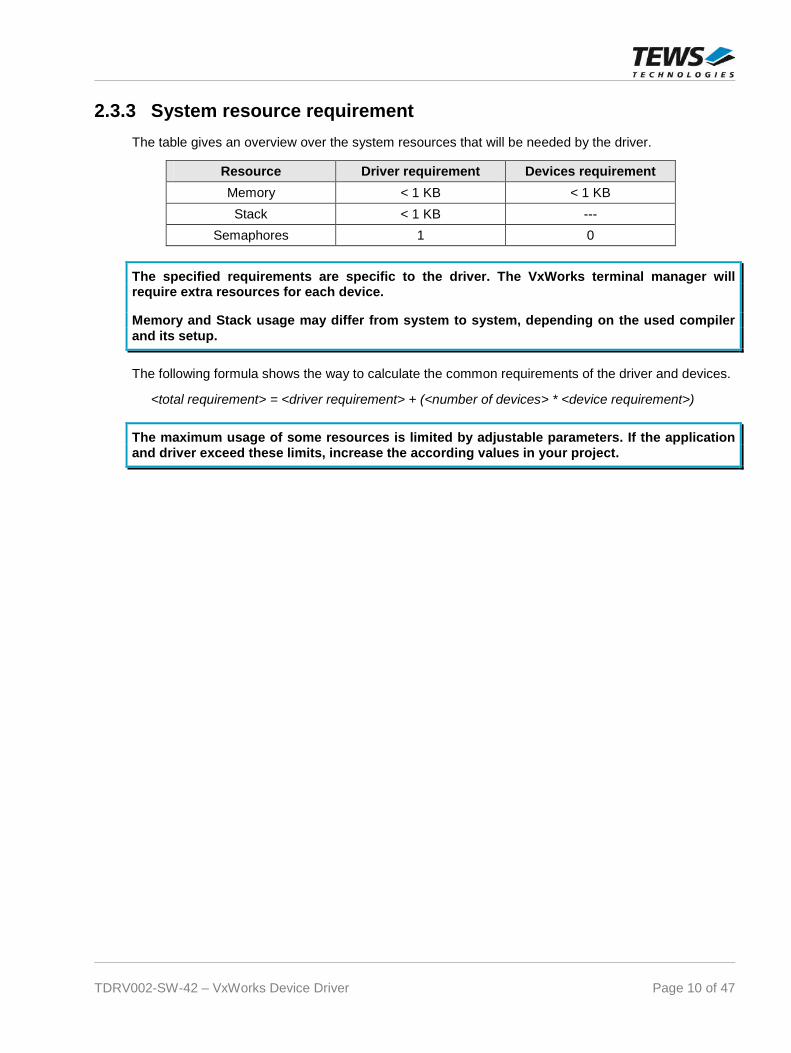
2.3.3 System resource requirement
The table gives an overview over the system resources that will be needed by the driver.
Resource Driver requirement Devices requirement
Memory < 1 KB < 1 KB
Stack < 1 KB ---
Semaphores 1 0
The specified requirements are specific to the driver. The VxWorks terminal manager willrequire extra resources for each device.
Memory and Stack usage may differ from system to system, depending on the used compilerand its setup.
The following formula shows the way to calculate the common requirements of the driver and devices.
<total requirement> = <driver requirement> + (<number of devices> * <device requirement>)
The maximum usage of some resources is limited by adjustable parameters. If the applicationand driver exceed these limits, increase the according values in your project.

TDRV002-SW-42 – VxWorks Device Driver Page 11 of 47
3 VxBus driver supportThe TDRV002 will be fully integrated to the VxWorks system and the devices will be automaticallycreated when booting VxWorks.
3.1 Assignment of Port Names
The port names are assigned automatically when the ports are created. The assigned port name willbe ‘/tyCo/<n>” where <n> specifies the port number. Generally the first two port numbers (‘/tyCo/0’,‘/tyCo/1’) are assigned to system ports and the additional ports on the TDRV002 supported boards willstart with port number 2. For example a system with one TPMC462 (4 channels) will assign thefollowing device names:
/tyCo/0 1st
system port
/tyCo/1 2nd
system port
/tyCo/2 1st
channel of TPMC462
/tyCo/3 2nd
channel of TPMC462
/tyCo/4 3rd
channel of TPMC462
/tyCo/5 4th
channel of TPMC462
If there is more than one supported TDRV002 board installed, the assignment of the channel numbersto the boards depends on the search order of the system, but all the channels of one board will followup in a row. For example a system with one TPMC462 (4 channels) and one TPMC372(4 channels) may assign the following two device names tables.
(TPMC462 found first) (TPMC372 found first)
/tyCo/0 1st
system port 1st
system port
/tyCo/1 2nd
system port 2nd
system port
/tyCo/2 1st
channel of TPMC462 1st
channel of TPMC372
/tyCo/3 2nd
channel of TPMC462 2nd
channel of TPMC372
/tyCo/4 3rd
channel of TPMC462 3rd
channel of TPMC372
/tyCo/5 4th
channel of TPMC462 4th
channel of TPMC372
/tyCo/6 1st
channel of TPMC372 1st
channel of TPMC462
/tyCo/7 2nd
channel of TPMC372 2nd
channel of TPMC462
/tyCo/8 3rd
channel of TPMC372 3rd
channel of TPMC462
/tyCo/9 4th
channel of TPMC372 4th
channel of TPMC462
After booting the available devices can be checked with devs(). This function will return a list of allcreated devices. If less devices have been created, please first check the defined maximum number ofserial devices. (See 2.2.2 Modification of the ‘Number of serial ports’)
TDRV002-SW-42 – VxWorks Device Driver Page 12 of 47
3.2 VxBus Error Codes
There will be just system generated return codes for the ‘Basic I/O Functions’. The TDRV002 specific‘Error Codes’ described with the functions are not valid for VxBus devices.
3.3 Default Configuration
The driver will create the port with the following default configuration:
9600 Baud 8 Data- and 1 Stopbit FIFO enabled (Triggerlevels: Rx = 56 – Tx = 8)
Ports supporting a programmable interface (e.g. TPMC465) will startup with a disabled interface.Before using the port it must be configure with the corresponding ioctl-function (FIOSETINTERFACE).
3.4 Compatibility to pre-VxBus applications
A driver and device installation after system start like it has been common in pre-VxBus systems is nolonger required. Therefore all legacy system I/O functions are obsolete. These functions areimplemented to keep the driver compatible to older driver versions. The obsolete functions only checkif the driver is already installed or devices are present. The functions do not guarantee fullcompatibility because port name assignment and the search order of the modules have changed.
TDRV002-SW-42 – VxWorks Device Driver Page 13 of 47
4 Legacy I/O system functionsThis chapter describes the driver-level interface to the I/O system. The purpose of these functions is toinstall the driver in the I/O system, add and initialize devices.
The legacy I/O system functions are only relevant for the legacy TDRV002 driver. For theVxBus-enabled TDRV002 driver, the driver will be installed automatically in the I/O system anddevices will be created as needed for detected modules.
4.1 tdrv002Drv()
NAME
tdrv002Drv() - installs the TDRV002 driver in the I/O system.
This function is not necessary for systems supporting VxBus. It is a dummy function whichchecks if the driver is installed. It has been implemented to keep the application compatible tothe legacy version.
SYNOPSIS
#include “tdrv002.h”
STATUS tdrv002Drv(
void)
DESCRIPTION
This function searches for devices on the PCI bus and installs the TDRV002 driver in the I/O system.
A call to this function is the first thing the user has to do before adding any device to thesystem or performing any I/O request.

TDRV002-SW-42 – VxWorks Device Driver Page 14 of 47
EXAMPLE
#include "tdrv002.h”
STATUS result;
/*---------------------
Initialize Driver
---------------------*/
result = tdrv002Drv();
if (result == ERROR)
{
/* error handling */
}
RETURNS
OK or ERROR. If the function fails an error code will be stored in errno.
ERROR CODES
The error codes are stored in errno and can be read with the function errnoGet().
Error code Description
S_tdrv002Drv_NOMEM Driver cannot allocate memory
S_tdrv002Drv_NXIO No device found
SEE ALSO
VxWorks Programmer’s Guide: I/O System

TDRV002-SW-42 – VxWorks Device Driver Page 15 of 47
4.2 tdrv002DevCreate()
NAME
tdrv002DevCreate() – Adds TDRV002 device to the system and initializes the device hardware withthe specified configuration
SYNOPSIS
#include “tdrv002.h”
STATUS tdrv002DevCreate(
char *name,int glbChanNo,int rdBufSize,int wrtBufSize,TDRV002_CHANCONF *devConf
)
DESCRIPTION
This routine creates a device on a specified serial channel that will be serviced by the TDRV002driver.
This function must be called before performing any I/O request to this device.
This function is not necessary for systems supporting VxBus. It is a dummy function whichchecks if the device is installed. It has been implemented to keep the application compatible topre-VxBus versions. All parameters except of glbChanNo will be ignored.
PARAMETER
name
This string specifies the name of the device that will be used to identify the device, for examplefor open() calls.

TDRV002-SW-42 – VxWorks Device Driver Page 16 of 47
glbChanNo
This index number specifies the device to add to the system.The index number depends on the search priority of the modules. The modules will be searchedin the following order:
TPMC371-10, -11, -12, TPMC372-xx, TPMC375-xx,TPMC376-xx,TPMC460-xx, TPMC461-xx, TPMC462-xx,TPMC463-xx, TPMC465-xx, TPMC466-xx,TPMC467-xx,TCP460-xx, TCP461-x, TCP462-xx,TCP463-xx, TCP465-xx, TCP466-xx,TCP467-xx
If modules of the same type are installed the channel numbers will be assigned in the order theVxWorks pciFindDevice() function will find the devices.
Example: (A system with 2x TPMC461-10, 1x TPMC372-10, 1x TPMC372-11) will assign thefollowing device indices:
Module Device Index
TPMC372-10 0 ... 3
TPMC372-11 4 … 7
TPMC461-10 (1st) 8 … 15
TPMC461-10 (2nd
) 16 … 23
For VxBus support this is the only used parameter.
The glbChanNo specifies the SIO-port- number including non TDRV002 ports. Normallythere are two local SIO-ports configured to the system and than the TDRV002-ports willfollow. That means the first TDRV002 port will be specified with glbChanNo set to 2.
The module and port enumeration depends on the VxWorks system. It is not made by thedriver and the description of the port ordering above is not valid for the VxBus version ofthe driver.
See also the chapter 3.1 Assignment of Port Names
rdBufSize
This value specifies the size of the receive software FIFO.
wrtBufSize
This value specifies the size of the transmit software FIFO.
TDRV002-SW-42 – VxWorks Device Driver Page 17 of 47
devConf
This parameter points to a structure (TDRV002_CHANCONFIG) containing the defaultconfiguration of the channel. (This function will be used for reconfigurations).
typedef struct
{
unsigned long baudrate;
unsigned long comPara;
unsigned char rxFSize;
unsigned char txFSize;
int options;
} TDRV002_CHANCONFIG;
baudrate
Selects the initial baud rate of the channel. (Allowed values depend on hardware)
comPara
This value is a field of ORed definitions, specifying the channel setup. One value of everygroup must be ORed into the value.
Number of data bits:
TDRV002_DATABIT_5 word length = 5 bit
TDRV002_DATABIT_6 word length = 6 bit
TDRV002_DATABIT_7 word length = 7 bit
TDRV002_DATABIT_8 word length = 8 bit
Length of stop bit:
TDRV002_STOPBIT_1 stop bit length = 1 bit
TDRV002_STOPBIT_1_5 stop bit length = 1.5 bit, (only data length 5)
TDRV002_STOPBIT_2 stop bit length = 2 bit, (only data length 6, 7, 8)
Parity mode:
TDRV002_PARITY_NO parity is disabled
TDRV002_PARITY_ODD odd parity is used
TDRV002_PARITY_EVEN even parity is used
TDRV002_PARITY_MARK a mark parity bit is used
TDRV002_PARITY_SPACE a space parity bit is used
Hardware handshake:
TDRV002_HWHS_DISABLE hardware handshake is disabled
TDRV002_HWHS_ENABLE hardware handshake is enabled (only if FIFO isenabled)
TDRV002-SW-42 – VxWorks Device Driver Page 18 of 47
FIFO mode:
TDRV002_FIFO_DISABLE Hardware FIFO is disabled
TDRV002_FIFO_ENABLE Hardware FIFO is enabled. Receiver andtransmitter trigger level must be set in rxFSize andtxFSize.
Local loopback mode:
TDRV002_LOCALLOOP_DISABLE Disable local loopback mode
TDRV002_LOCALLOOP_ENABLE Enabled local loopback mode
Interface configuration (only valid for programmable I/O interfaces):(A combination of the flags below must be specified to configure the interface)
TDRV002_TRANS_RS485_RS232_SEL RS485/RS232# configuration pin
TDRV002_TRANS_HDPLX_SEL HDPLX configuration pin
TDRV002_TRANS_RENA_SEL RENA configuration pin
TDRV002_TRANS_RTERM_SEL RTERM configuration pin
TDRV002_TRANS_TTERM_SEL TTERM configuration pin
TDRV002_TRANS_SLEWLIMIT_SEL SLEWLIMIT configuration pin
TDRV002_TRANS_SHDN_SEL SHDN configuration pin
TDRV002_AUTO_RS485_SEL_ENABLE enable Auto RS485 Operation mode ofXR17D15x
The function of the interface configuration pins can be found in the correspondinghardware User Manual.
There are predefined values of the interface configuration described in the hardwaremanual, you can just OR the predefined value instead of a list of configuration flags.Below is a list of the values:
TDRV002_INTF_OFF interface disabled
TDRV002_INTF_RS232 RS232
TDRV002_INTF_RS422 RS422 (Multidrop / Full duplex)
TDRV002_INTF_RS485FDM RS485 (Full duplex master)
TDRV002_INTF_RS485FDS RS485 (Full duplex slave)
TDRV002_INTF_RS485HD RS485 (Half duplex)
rxFSize
Specifies the HW receiver trigger level if the HW FIFO is enabled. Allowed valuesare 1 … 64
txFSize
Specifies the HW transmitter trigger level if the HW FIFO is enabled. Allowed valuesare 1 … 64.
options
Selects the initial VxWorks driver options. (Please refer to VxWorks manuals)

TDRV002-SW-42 – VxWorks Device Driver Page 19 of 47
EXAMPLE
#include "tdrv002.h”
STATUS result;
TDRV002_CHANCONF tdrv002conf;
/*-------------------------------------------------------
Create the device "/tyCo/2" on channel 0
read and write buffer sizes of 1024 byte.
Baudrate: 115200Baud
Databits: 8
Stopbits: 1
Parity: off
Handshake: off
FIFOs: enabled
Rx Trigger: more than 30 characters in FIFO
Tx Trigger: less than 10 characters in FIFO
Local Loop: off
Options: raw mode
I/O interface:RS232
-------------------------------------------------------*/
tdrv002conf.baudrate = 115200;
tdrv002conf.comPara = TDRV002_DATABIT_8 |
TDRV002_STOPBIT_1 |
TDRV002_PARITY_NO |
TDRV002_HWHS_DISABLE |
TDRV002_FIFO_ENABLE |
TDRV002_LOCALLOOP_DISABLE |
TDRV002_INTF_RS232;
tdrv002conf.rxFSize = 30;
tdrv002conf.txFSize = 10;
tdrv002conf.options = 10;
result = tdrv002DevCreate ("/tyCo/2", 0, 1024, 1024, &tdrv002conf);
if (result == OK)
{
/* Device successfully created */
}
else
{
/* Error occurred when creating the device */
}

TDRV002-SW-42 – VxWorks Device Driver Page 20 of 47
RETURNS
OK or ERROR. If the function fails an error code will be stored in errno.
ERROR CODES
The error codes are stored in errno and can be read with the function errnoGet().
Error code Description
S_tdrv002Drv_NODRV The TDRV002 Driver is not installed
S_tdrv002Drv_NODEV Specified device not found
S_tdrv002Drv_EXISTS The specified device has already been created
S_tdrv002Drv_ILLINTF Illegal interface specified
S_tdrv002Drv_ILLBAUD Illegal default baud rate specified
S_tdrv002Drv_ILLPARAM Illegal parameter specified
S_tdrv002Drv_MODENOTSUPP Unsupported default mode specified
S_tdrv002Drv_CONFERR Configuration error (specified flags exclude each other)
SEE ALSO
VxWorks Programmer’s Guide: I/O System
TDRV002-SW-42 – VxWorks Device Driver Page 21 of 47
4.3 tdrv002PciInit()
NAME
tdrv002PciInit() – Generic PCI device initialization
SYNOPSIS
void tdrv002PciInit(
void)
DESCRIPTION
This function is required only for Intel x86 VxWorks platforms. The purpose is to setup the MMUmapping for all required TDRV002 PCI spaces (base address register) and to enable the TDRV002device for access.
The global variable tdrv002Status obtains the result of the device initialization and can be polled laterby the application before the driver will be installed.
Value Meaning
> 0 Initialization successful completed. The value of tdrv002Status is equal to thenumber of mapped PCI spaces
0 No TDRV002 device found
< 0 Initialization failed. The value of (tdrv002Status & 0xFF) is equal to the number ofmapped spaces until the error occurs.
Possible cause: Too few entries for dynamic mappings in sysPhysMemDesc[].
Remedy: Add dummy entries as necessary (syslib.c).
This function is only supported for the TDRV002 legacy version. It must not be used with theVxBus version.
EXAMPLE
extern void tdrv002PciInit();
tdrv002PciInit();

TDRV002-SW-42 – VxWorks Device Driver Page 22 of 47
5 Basic I/O Functions
5.1 open()
NAME
open() - open a device or file.
SYNOPSIS
int open(
const char *name,int flags,int mode
)
DESCRIPTION
Before I/O can be performed to the TDRV002 device, a file descriptor must be opened by invoking thebasic I/O function open().
PARAMETER
name
Specifies the device which shall be opened.For the legacy driver version, the name specified in tdrv002DevCreate() must be used.For the VxBus driver version the system assigned device name must be used. (See also3.1 Assignment of Port Names)
flags
Not used
mode
Not used

TDRV002-SW-42 – VxWorks Device Driver Page 23 of 47
EXAMPLE
int fd;
/*------------------------------------------
Open the device named "/tyCo/2" for I/O
------------------------------------------*/
fd = open("/tyCo/2", 0, 0);
if (fd == ERROR)
{
/* error handling */
}
RETURNS
A device descriptor number or ERROR. If the function fails an error code will be stored in errno.
ERROR CODES
The error code can be read with the function errnoGet().
The error code is a standard error code set by the I/O system (see VxWorks Reference Manual.
SEE ALSO
ioLib, basic I/O routine - open()
TDRV002-SW-42 – VxWorks Device Driver Page 24 of 47
5.2 close()
NAME
close() – close a device or file
SYNOPSIS
STATUS close(
int fd)
DESCRIPTION
This function closes opened devices.
PARAMETER
fd
This file descriptor specifies the device to be closed. The file descriptor has been returned bythe open() function.
EXAMPLE
int fd;
STATUS retval;
/*----------------
close the device
----------------*/
retval = close(fd);
if (retval == ERROR)
{
/* error handling */
}
RETURNS
OK or ERROR. If the function fails, an error code will be stored in errno.
TDRV002-SW-42 – VxWorks Device Driver Page 25 of 47
ERROR CODES
The error code can be read with the function errnoGet().
The error code is a standard error code set by the I/O system (see VxWorks Reference Manual).
SEE ALSO
ioLib, basic I/O routine - close()

TDRV002-SW-42 – VxWorks Device Driver Page 26 of 47
5.3 read()
NAME
read() – read data from a specified device.
SYNOPSIS
int read(
int fd,char *buffer,size_t maxbytes
)
DESCRIPTION
This function can be used to read data from the device.
PARAMETER
fd
This file descriptor specifies the device to be used. The file descriptor has been returned by theopen() function.
buffer
This argument points to a user supplied buffer. The returned data will be filled into this buffer.
maxbytes
This parameter specifies the maximum number of read bytes (buffer size).
EXAMPLE
#define BUFSIZE 100
int fd;
char buffer[BUFSIZE];
int retval;
…

TDRV002-SW-42 – VxWorks Device Driver Page 27 of 47
…
/*-----------------------------
Read data from TDRV002 device
-----------------------------*/
retval = read(fd, buffer, BUFSIZE);
if (retval != ERROR)
{
printf(“%d bytes read\n”, retval);
}
else
{
/* handle the read error */
}
RETURNS
Number of bytes read or ERROR. If the function fails an error code will be stored in errno.
ERROR CODES
The error code can be read with the function errnoGet().
The error code is a standard error code set by the I/O system (see VxWorks Reference Manual.
SEE ALSO
ioLib, basic I/O routine - read()

TDRV002-SW-42 – VxWorks Device Driver Page 28 of 47
5.4 write()
NAME
write() – write data from a buffer to a specified device.
SYNOPSIS
int write(
int fd,char *buffer,size_t nbytes
)
DESCRIPTION
This function can be used to write data to the device.
PARAMETER
fd
This file descriptor specifies the device to be used. The file descriptor has been returned by theopen() function.
buffer
This argument points to a user supplied buffer. The data of the buffer will be written to thedevice.
nbytes
This parameter specifies the number of bytes to be written.
EXAMPLE
int fd;
char buffer[] = “Hello World”;
int retval;
…

TDRV002-SW-42 – VxWorks Device Driver Page 29 of 47
…
/*------------------------------
Write data to a TDRV002 device
------------------------------*/
retval = write(fd, buffer, strlen(buffer));
if (retval != ERROR)
{
printf(“%d bytes written\n”, retval);
}
else
{
/* handle the write error */
}
RETURNS
Number of bytes written or ERROR. If the function fails an error code will be stored in errno.
ERROR CODES
The error code can be read with the function errnoGet().
The error code is a standard error code set by the I/O system (see VxWorks Reference Manual).
SEE ALSO
ioLib, basic I/O routine - write()

TDRV002-SW-42 – VxWorks Device Driver Page 30 of 47
5.5 ioctl()
NAME
ioctl() - performs an I/O control function.
SYNOPSIS
#include “tdrv002.h”
int ioctl(
int fd,int request,int arg
)
DESCRIPTION
Special I/O operation that do not fit to the standard basic I/O calls (read, write) will be performed bycalling the ioctl() function.
PARAMETER
fd
This file descriptor specifies the device to be used. The file descriptor has been returned by theopen() function.
request
This argument specifies the function that shall be executed. The TDRV002 device driver usesthe standard tty driver support library tyLib. For details of supported ioctl functions see VxWorksReference Manual: tyLib and VxWorks Programmer's Guide: I/O System. Following additionalfunctions are defined:
Function Description
FIODATABITS Set length of data word
FIOSTOPBITS Set length of the stop bit
FIOPARITY Set parity checking mode
FIOHWHS Enable/Disable hardware handshake mode
FIOSETBREAK Set/Release Break
FIORECONFIGURE Reconfigure device with the default parameters
FIOSTATUS Get state of the device
FIOLOCALLOOP Enable/Disable local loopback mode
FIOLOCALSELFTEST Execute a local self test
FIOSETINTERFACE Change the programmable I/O interface
TDRV002-SW-42 – VxWorks Device Driver Page 31 of 47
arg
This parameter depends on the selected function (request). How to use this parameter isdescribed below with the function.
RETURNS
OK or ERROR. If the function fails an error code will be stored in errno.
ERROR CODES
The error code can be read with the function errnoGet().
For TDRV002 legacy driver version: The error code is a standard error code set by the I/O system(see VxWorks Reference Manual). Function specific error codes will be described with the function.
For TDRV002 VxBus driver version: The error code is always a standard error code set by the I/Osystem. There are no driver specific error codes.
SEE ALSO
ioLib, basic I/O routine - ioctl()

TDRV002-SW-42 – VxWorks Device Driver Page 32 of 47
5.5.1 FIOBAUDRATE
This I/O control function sets up a new baudrate. The function specific control parameter arg specifiesthe new baudrate.
EXAMPLE
#include “tdrv002.h”
int fd;
int retval;
/*---------------------
Set baud rate to 9600
---------------------*/
retval = ioctl(fd, FIOBAUDRATE, 9600);
if (retval != ERROR)
{
/* function succeeded */
}
else
{
/* handle the error */
}
ERROR CODES
Error code Description
S_tdrv002Drv_SELFTESTBUSY Self test mode is active for the device
S_tdrv002Drv_ILLBAUD Illegal baud rate specified
TDRV002-SW-42 – VxWorks Device Driver Page 33 of 47
5.5.2 FIODATABITS
This I/O control function sets the data word length. The function specific control parameter argspecifies the length of the data word. The following values are defined:
Value Description
TDRV002_DATABIT_5 word length = 5 bit
TDRV002_DATABIT_6 word length = 6 bit
TDRV002_DATABIT_7 word length = 7 bit
TDRV002_DATABIT_8 word length = 8 bit
EXAMPLE
#include “tdrv002.h”
int fd;
int retval;
/*-------------------------------------
Set channel to a word length of 7 bit
-------------------------------------*/
retval = ioctl(fd, FIODATABITS, TDRV002_DATABIT_7);
if (retval != ERROR)
{
/* function succeeded */
}
else
{
/* handle the error */
}
ERROR CODES
Error code Description
S_tdrv002Drv_SELFTESTBUSY Self test mode is active for the device
S_tdrv002Drv_ILLPARAM Illegal data word length specified
TDRV002-SW-42 – VxWorks Device Driver Page 34 of 47
5.5.3 FIOSTOPBITS
This I/O control function sets the length of the stop bit. The function specific control parameter argspecifies the length of the stop bit word. The following values are defined:
Value Description
TDRV002_STOPBIT_1 stop bit length = 1 bit
TDRV002_STOPBIT_1_5 stop bit length = 1.5 bit, (only data length 5)
TDRV002_STOPBIT_2 stop bit length = 2 bit, (only data length 6, 7, 8)
EXAMPLE
#include “tdrv002.h”
int fd;
int retval;
/*-----------------------------------------
Set channel to a stop bit length of 1 bit
-----------------------------------------*/
retval = ioctl(fd, FIOSTOPBITS, TDRV002_STOPBIT_1);
if (retval != ERROR)
{
/* function succeeded */
}
else
{
/* handle the error */
}
ERROR CODES
Error code Description
S_tdrv002Drv_SELFTESTBUSY Self test mode is active for the device
S_tdrv002Drv_ILLPARAM Illegal data stop bit length specified

TDRV002-SW-42 – VxWorks Device Driver Page 35 of 47
5.5.4 FIOPARITY
This I/O control function sets the parity mode. The function specific control parameter arg specifies thenew parity mode. The following values are defined:
Value Description
TDRV002_PARITY_NO parity is disabled
TDRV002_PARITY_ODD odd parity is used
TDRV002_PARITY_EVEN even parity is used
TDRV002_PARITY_MARK a mark parity bit is used
TDRV002_PARITY_SPACE a space parity bit is used
EXAMPLE
#include “tdrv002.h”
int fd;
int retval;
/*---------------------------
Configure channel no parity
---------------------------*/
retval = ioctl(fd, FIOPARITY, TDRV002_PARITY_NO);
if (retval != ERROR)
{
/* function succeeded */
}
else
{
/* handle the error */
}
ERROR CODES
Error code Description
S_tdrv002Drv_SELFTESTBUSY Self test mode is active for the device
S_tdrv002Drv_ILLPARAM Illegal parity mode specified
TDRV002-SW-42 – VxWorks Device Driver Page 36 of 47
5.5.5 FIOHWHS
This I/O control function enables or disables the hardware handshake. The function specific controlparameter arg specifies if the hardware handshake shall be enabled or disabled. The following valuesare defined:
Value Description
TDRV002_HWHS_DISABLE hardware handshake is disabled
TDRV002_HWHS_ENABLE hardware handshake is enabled (only if FIFO isenabled)
EXAMPLE
#include “tdrv002.h”
int fd;
int retval;
/*--------------------------
Disable hardware handshake
--------------------------*/
retval = ioctl(fd, FIOHWHS, TDRV002_HWHS_DISABLE);
if (retval != ERROR)
{
/* function succeeded */
}
else
{
/* handle the error */
}
ERROR CODES
Error code Description
S_tdrv002Drv_SELFTESTBUSY Self test mode is active for the device
S_tdrv002Drv_ILLPARAM Illegal handshake mode specified
S_tdrv002Drv_MODENOTSUPP The hardware does not support the specified mode
TDRV002-SW-42 – VxWorks Device Driver Page 37 of 47
5.5.6 FIOSETBREAK
This I/O control function sets or resets break state on transmit line. The function specific controlparameter arg specifies the state on transmit line. The following values are defined:
Value Description
TDRV002_BREAK_SET Set break on transmit line(s)
TDRV002_BREAK_RESET Reset break on transmit line(s)
EXAMPLE
#include “tdrv002.h”
int fd;
int retval;
/*-----------------------
Set break on Tx line(s)
-----------------------*/
retval = ioctl(fd, FIOSETBREAK, TDRV002_BREAK_SET);
if (retval != ERROR)
{
/* function succeeded */
}
else
{
/* handle the error */
}
ERROR CODES
Error code Description
S_tdrv002Drv_SELFTESTBUSY Self test mode is active for the device
S_tdrv002Drv_ILLPARAM Illegal parameter specified
TDRV002-SW-42 – VxWorks Device Driver Page 38 of 47
5.5.7 FIORECONFIGURE
This I/O control function resets the device to the default configuration. The function specific controlparameter arg is not used for this function.
EXAMPLE
#include “tdrv002.h”
int fd;
int retval;
/*--------------------------
Reconfigure serial channel
--------------------------*/
retval = ioctl(fd, FIORECONFIGURE, 0);
if (retval != ERROR)
{
/* function succeeded */
}
else
{
/* handle the error */
}
ERROR CODES
Error code Description
S_tdrv002Drv_SELFTESTBUSY Self test mode is active for the device

TDRV002-SW-42 – VxWorks Device Driver Page 39 of 47
5.5.8 FIOSTATUS
This I/O control function returns the state of the device. The function specific control parameter argpoints to a buffer (unsigned long) the status will be returned. The returned status is an OR’ed value ofthe following flags:
Value Description
TDRV002_STATUS_FRAMINGERR This bit is set if a framing error has been detectedsince the last call.
TDRV002_STATUS_PARITYERR This bit is set if a parity error has been detectedsince the last call.
TDRV002_STATUS_OVERRUNERR This bit is set if an overrun error has been detectedsince the last call.
TDRV002_STATUS_PENDBREAK This bit is set if a break signal has been detectedsince the last call.
EXAMPLE
#include “tdrv002.h”
int fd;
int retval;
unsigned long inStat;
/*------------------
Get receive status
------------------*/
retval = ioctl(fd, FIOSTATUS, (int)&inStat);
if (retval != ERROR)
{
/* function succeeded */
if (inStat & TDRV002_STATUS_FRAMINGERR)
{
/* Framing error occurred */
}
}
else
{
/* handle the error */
}

TDRV002-SW-42 – VxWorks Device Driver Page 40 of 47
5.5.9 FIOLOCALLOOP
This I/O control function enables or disables the local loop back mode. The function specific controlparameter arg specifies if the local loop back shall be enabled or disabled. The following values aredefined:
Value Description
TDRV002_LOCALLOOP_DISABLE Local loopback mode is disabled
TDRV002_LOCALLOOP_ENABLE Local loopback mode is enabled
EXAMPLE
#include “tdrv002.h”
int fd;
int retval;
/*---------------------------
Disable local loopback mode
---------------------------*/
retval = ioctl(fd, FIOLOCALLOOP, TDRV002_LOCALLOOP_DISABLE);
if (retval != ERROR)
{
/* function succeeded */
}
else
{
/* handle the error */
}
ERROR CODES
Error code Description
S_tdrv002Drv_SELFTESTBUSY Self test mode is active for the device
S_tdrv002Drv_ILLPARAM Illegal parameter specified

TDRV002-SW-42 – VxWorks Device Driver Page 41 of 47
5.5.10 FIOLOCALSELFTEST
This I/O control function executes a local selftest of the specified device. . The local loopback modewill be used to check the communication and all local I/O signals(RxD/TxD/RTS/CTS/DTR/DSR/RI/CD) are used. The function can be executed with applicationsupplied Rx/Tx buffers or with driver allocated buffers. The function will return a status if the test hasbeen executed.
The self test function executes in task context. Therefore it must be guaranteed that the callingtask can execute. Otherwise the self test function may fail, even though if the hardware is OK.
The function specific control parameter arg points to a supplied buffer(TDRV002_LOCALSELFTEST_BUFFER). The following values are defined:
typedef struct
{
char *transmitBuffer;
int transmitSize;
char *receiveBuffer;
int receiveSize;
int receiveCount;
unsigned long status;
} TDRV002_LOCALSELFTEST_BUFFER;
transmitBuffer
This is a pointer to a buffer with data that should be transmitted with the local loopback test.This allows the application to check the transmitted data and select the content and size of thetest data.
transmitSize
This argument specifies the size of the transmitBuffer. If this argument is set to 0 or to anegative value the driver will allocate a buffer and create test data automatically. If automaticallyallocated buffers are used, the parameters transmitBuffer, receiveBuffer, receiveSize andreceiveCount will be ignored.
receiveBuffer
This is a pointer to a buffer that will return the locally transmitted data. This buffer can be usedto compare received and transmitted data.
receiveSize
This argument specifies the size of the receive buffer. The size of the receive buffer must be atleast as big as the transmit buffer.
receiveCount
This is the count of characters that have been received during the selftest. The returned valueshould be the same as transmitSize.
TDRV002-SW-42 – VxWorks Device Driver Page 42 of 47
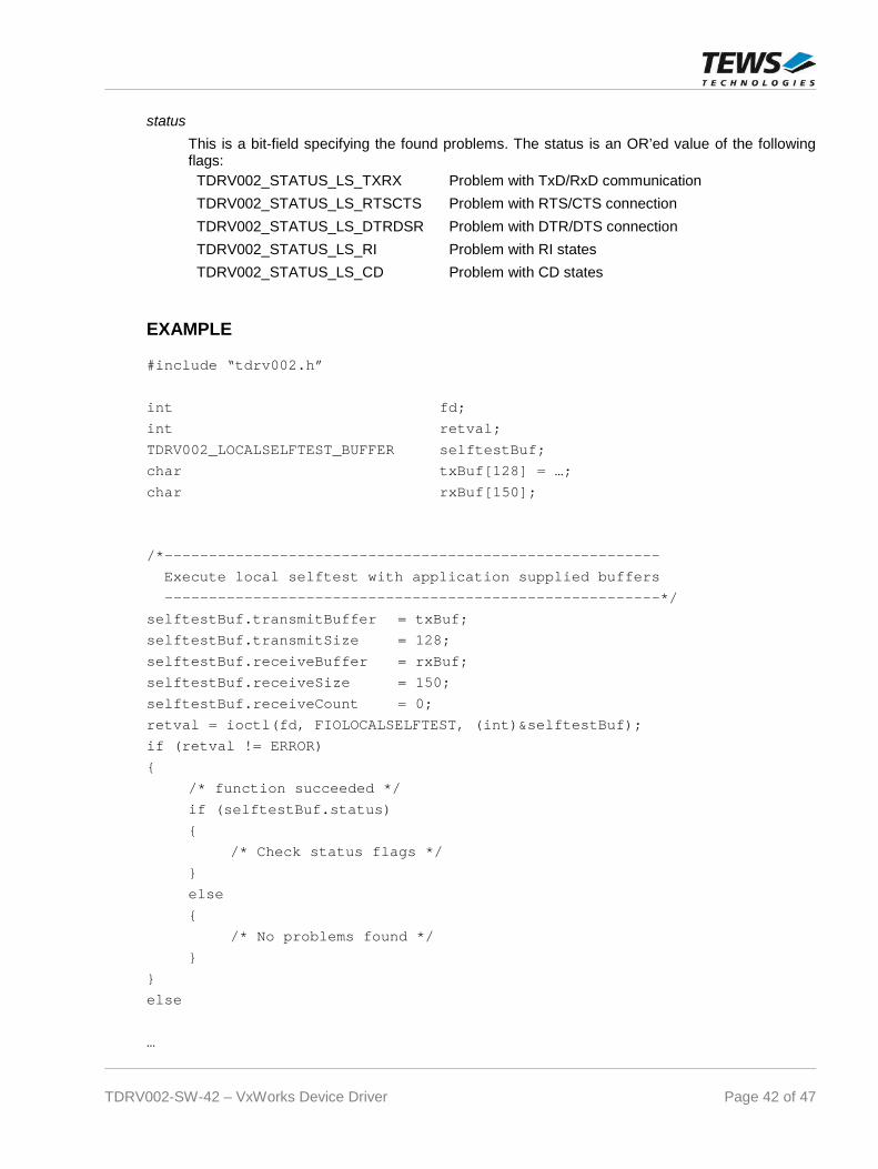
status
This is a bit-field specifying the found problems. The status is an OR’ed value of the followingflags:
TDRV002_STATUS_LS_TXRX Problem with TxD/RxD communication
TDRV002_STATUS_LS_RTSCTS Problem with RTS/CTS connection
TDRV002_STATUS_LS_DTRDSR Problem with DTR/DTS connection
TDRV002_STATUS_LS_RI Problem with RI states
TDRV002_STATUS_LS_CD Problem with CD states
EXAMPLE
#include “tdrv002.h”
int fd;
int retval;
TDRV002_LOCALSELFTEST_BUFFER selftestBuf;
char txBuf[128] = …;
char rxBuf[150];
/*--------------------------------------------------------
Execute local selftest with application supplied buffers
--------------------------------------------------------*/
selftestBuf.transmitBuffer = txBuf;
selftestBuf.transmitSize = 128;
selftestBuf.receiveBuffer = rxBuf;
selftestBuf.receiveSize = 150;
selftestBuf.receiveCount = 0;
retval = ioctl(fd, FIOLOCALSELFTEST, (int)&selftestBuf);
if (retval != ERROR)
{
/* function succeeded */
if (selftestBuf.status)
{
/* Check status flags */
}
else
{
/* No problems found */
}
}
else
…
TDRV002-SW-42 – VxWorks Device Driver Page 43 of 47
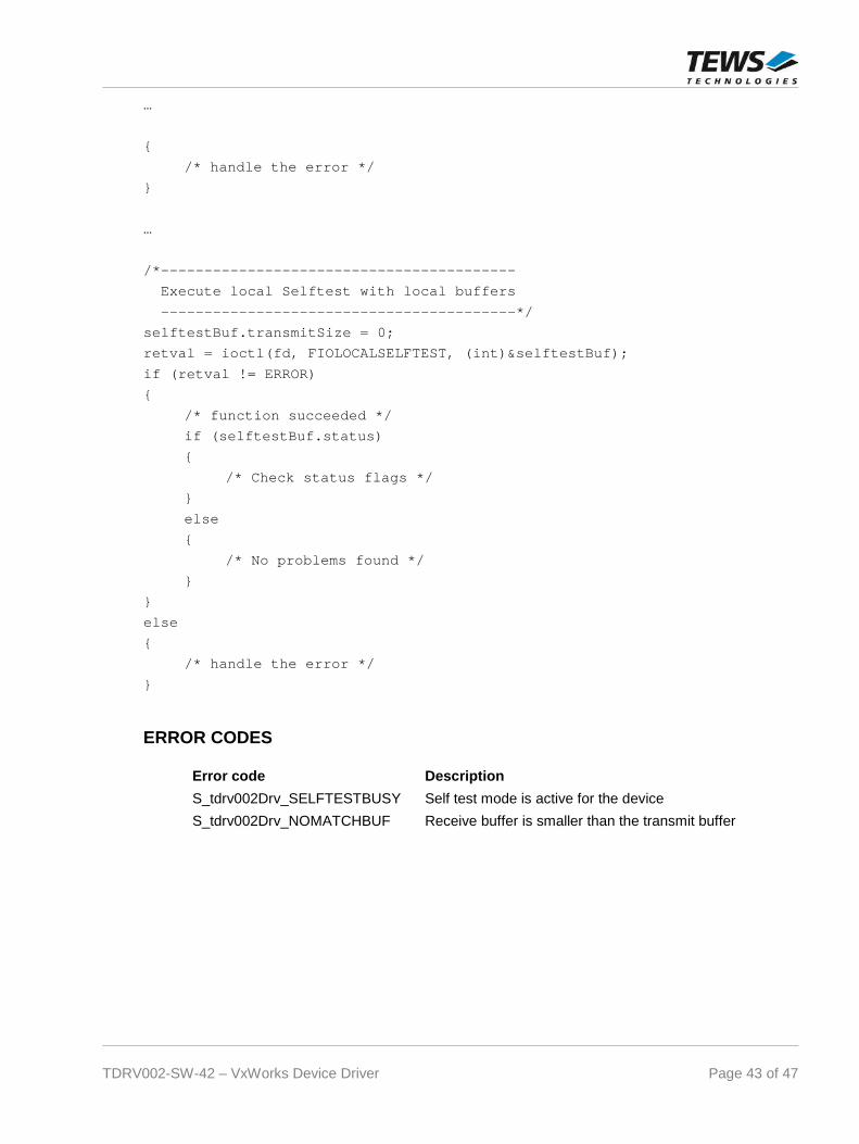
…
{
/* handle the error */
}
…
/*-----------------------------------------
Execute local Selftest with local buffers
-----------------------------------------*/
selftestBuf.transmitSize = 0;
retval = ioctl(fd, FIOLOCALSELFTEST, (int)&selftestBuf);
if (retval != ERROR)
{
/* function succeeded */
if (selftestBuf.status)
{
/* Check status flags */
}
else
{
/* No problems found */
}
}
else
{
/* handle the error */
}
ERROR CODES
Error code Description
S_tdrv002Drv_SELFTESTBUSY Self test mode is active for the device
S_tdrv002Drv_NOMATCHBUF Receive buffer is smaller than the transmit buffer

TDRV002-SW-42 – VxWorks Device Driver Page 44 of 47
5.5.11 FIOSETINTERFACE
This I/O control function sets a new I/O interface configuration. This function is only usable for devicessupporting a programmable I/O interface. The function specific control parameter arg specifies thenew configuration of the programmable transceivers. (Only allowed for channels supporting aprogrammable I/O interface) A combination of the flags below must be specified to configure theinterface.
Value Description
TDRV002_TRANS_RS485_RS232_SEL RS485/RS232# configuration pin
TDRV002_TRANS_HDPLX_SEL HDPLX configuration pin
TDRV002_TRANS_RENA_SEL RENA configuration pin
TDRV002_TRANS_RTERM_SEL RTERM configuration pin
TDRV002_TRANS_TTERM_SEL TTERM configuration pin
TDRV002_TRANS_SLEWLIMIT_SEL SLEWLIMIT configuration pin
TDRV002_TRANS_SHDN_SEL SHDN configuration pin
TDRV002_AUTO_RS485_SEL_ENABLE enable Auto RS485 Operation mode ofXR17D15x
The function of the interface configuration pins can be found in the correspondinghardware User Manual.
There are predefined values of the interface configuration described in the hardware manual,you can just OR the predefined value instead of a list of configuration flags. Below is a list of thevalues:
Value Description
TDRV002_INTF_OFF interface disabled
TDRV002_INTF_RS232 RS232
TDRV002_INTF_RS422 RS422 (Multidrop / Full duplex)
TDRV002_INTF_RS485FDM RS485 (Full duplex master)
TDRV002_INTF_RS485FDS RS485 (Full duplex slave)
TDRV002_INTF_RS485HD RS485 (Half duplex)

TDRV002-SW-42 – VxWorks Device Driver Page 45 of 47
EXAMPLE
#include “tdrv002.h”
int fd;
int retval;
/*---------------------------------------
Set I/O interface for RS485 half duplex
---------------------------------------*/
retval = ioctl(fd, FIOSETINTERFACE, TDRV002_INTF_RS485HD);
if (retval != ERROR)
{
/* function succeeded */
}
else
{
/* handle the error */
}
ERROR CODES
Error code Description
S_tdrv002Drv_SELFTESTBUSY Self test mode is active for the device
S_tdrv002Drv_NOTSUPP The device has no programmable I/O interface
S_tdrv002Drv_ILLINTF The specified interface type is not supported by thedevice
S_tdrv002Drv_ILLBAUD The specified interface type can not support the currentbaud rate
S_tdrv002Drv_MODENOTSUPP Handshake mode is not supported for the specifiedinterface type

TDRV002-SW-42 – VxWorks Device Driver Page 46 of 47
6 Appendix
6.1 Debugging Driver Start-Up in VxBus-Systems
Driver start-up of the TDRV002 is mainly executed at a time which does not allow the output debugmessages. Therefore we have implemented a function that displays some information about driversstart-up phase.
STATUS tdrv002Show(
void)
The function will display the devices which are supported by the TDRV002-SW-42 and someadditional information about probing modules and errors.
For example, the function can be called from the VxWorks shell to display the information.
Below is an example output for an installed TPMC371:
-> tdrv002Show
TDRV002 devices:
/tyCo/2
/tyCo/3
/tyCo/4
/tyCo/5
/tyCo/6
/tyCo/7
/tyCo/8
/tyCo/9
Stats: ProbeCount: 1 - ProbeErrCount: 0 - NumDevs: 8
value = 0 = 0x0
->
The function only available if the VxBus driver is used.
6.2 Example Application Adaptation
The example application is written to support VxBus and legacy.
For Legacy support LEGACY_NAMES in tdrv002exa.c must be defined.
For VxBus support LEGACY_NAMES in tdrv002exa.c must not be defined.
TDRV002-SW-42 – VxWorks Device Driver Page 47 of 47
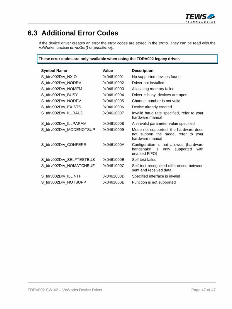
6.3 Additional Error Codes
If the device driver creates an error the error codes are stored in the errno. They can be read with theVxWorks function errnoGet() or printErrno().
These error codes are only available when using the TDRV002 legacy driver.
Symbol Name Value Description
S_tdrv002Drv_NXIO 0x04610001 No supported devices found
S_tdrv002Drv_NODRV 0x04610002 Driver not installed
S_tdrv002Drv_NOMEM 0x04610003 Allocating memory failed
S_tdrv002Drv_BUSY 0x04610004 Driver is busy, devices are open
S_tdrv002Drv_NODEV 0x04610005 Channel number is not valid
S_tdrv002Drv_EXISTS 0x04610006 Device already created
S_tdrv002Drv_ILLBAUD 0x04610007 Invalid baud rate specified, refer to yourhardware manual
S_tdrv002Drv_ILLPARAM 0x04610008 An invalid parameter value specified
S_tdrv002Drv_MODENOTSUP 0x04610009 Mode not supported, the hardware doesnot support the mode, refer to yourhardware manual
S_tdrv002Drv_CONFERR 0x0461000A Configuration is not allowed (hardwarehandshake is only supported withenabled FIFO)
S_tdrv002Drv_SELFTESTBUS 0x0461000B Self test failed
S_tdrv002Drv_NOMATCHBUF 0x0461000C Self test recognized differences betweensent and received data
S_tdrv002Drv_ILLINTF 0x0461000D Specified interface is invalid
S_tdrv002Drv_NOTSUPP 0x0461000E Function is not supported