tda programmingmanual
TRANSCRIPT

8/11/2019 TDA ProgrammingManual
http://slidepdf.com/reader/full/tda-programmingmanual 1/720
Thank you for purchasing a Panasonic Hybrid IP-PBX.
Please read this manual carefully before using this product and save this manual for future use.
KX-TDA50: PSMPR Software File Version 4.0000 or later
KX-TDA100/KX-TDA200: PMPR Software File Version 5.0000 or later
KX-TDA600: PLMPR Software File Version 5.0000 or later
Document Version: 2008-03
Hybrid IP-PBX
PC Programming Manual
www.voicesonic.com
Phone: 877-289-2829
Panasonic KX-TDA50
KX-TDA100
KX-TDA200
KX-TDA600
Panasonic KX-TDA50, KXTDA50, TDA50, KX-TDA100, KXTDA100, TDA100, KX-TDA200, KXTDA200, TDA200, KX-TDA600, KXTDA600, TDA600
Panasonic Telephone Systems
8/11/2019 TDA ProgrammingManual
http://slidepdf.com/reader/full/tda-programmingmanual 2/720
2 PC Programming Manual
Introduction
About this Programming ManualThe PC Programming Manual is designed to serve as a system programming reference for thePanasonic Hybrid IP-PBX. It explains how to program this PBX using the Maintenance Console
software.The PC Programming Manual is divided into the following sections:
Section 1, Overview
Provides an overview of programming the PBX.
Section 2, Maintenance Console Operating Instructions
Serves as reference operating instructions when using the Maintenance Console software toprogram the PBX.
Section 3, Appendix
Provides a list of all related PC programming items for each feature as Feature ProgrammingReferences.
References Found in the PC Programming Manual
Programming Manual References
Related sections of the PC Programming Manual are listed for your reference.
Feature Manual References
The Feature Manual explains what the PBX can do, as well as how to obtain the most of its manyfeatures and facilities. Sections from the Feature Manual are listed throughout this manual for your
reference.
Installation Manual References
The Installation Manual provides instructions detailing the installation and maintenance of the PBX.Sections from the Installation Manual are listed throughout this manual for your reference.
Links to Other Pages and ManualsIf you are viewing this manual with a PC, certain items are linked to different sections of this and otherPBX manuals. Click on a link to jump to that section.
Linked items include:
Installation Manual References
• PC Programming Manual References• Feature Manual References
WARNING
Unplug the PBX from the AC outlet if it emits smoke, an abnormal smell or makesunusual noise. These conditions can cause fire or electric shock. Confirm thatsmoke has stopped and contact an authorized Panasonic Factory Service Center.
8/11/2019 TDA ProgrammingManual
http://slidepdf.com/reader/full/tda-programmingmanual 3/720
PC Programming Manual 3
Trademarks• Microsoft, Windows, and Windows Vista are either registered trademarks or trademarks of
Microsoft Corporation in the United States and/or other countries.
• Intel and Celeron are trademarks or registered trademarks of Intel Corporation in the UnitedStates and other countries.
• All other trademarks identified herein are the property of their respective owners.
• Microsoft product screen shot(s) reprinted with permission from Microsoft Corporation.
NOTES• The contents of this manual apply to PBXs with a certain software version, as indicated on the
cover of this manual. To confirm the software version of your PBX, see How do I confirm the
software version of the PBX or installed cards? in 2.7.1 Frequently Asked Questions(FAQ).
• Some optional service cards, PTs, and features are not available in some areas. Additionally,some optional service cards and features are not available for some PBX models. Please consultyour certified Panasonic dealer for more information.
• Product specifications are subject to change without notice.
In some cases, additional information, including updates to this and other manuals, is includedin the Maintenance Console's Information before programming. Install the latest version ofMaintenance Console to view this information.
8/11/2019 TDA ProgrammingManual
http://slidepdf.com/reader/full/tda-programmingmanual 4/720
4 PC Programming Manual
Table of Contents
1 Overview..................................................................................................91.1 Introduction ....................................................................................................................10
1.1.1 Introduction ......................................................................................................................10
1.1.2 Entering Characters .........................................................................................................101.2 PC Programming............................................................................................................12
1.2.1 Installing and Starting the Maintenance Console.............................................................121.2.2 Password Security............................................................................................................15
2 Maintenance Console Operating Instructions ................................... 172.1 Introduction ....................................................................................................................18
2.1.1 Starting Maintenance Console and Software Modes.......................................................182.1.2 Access Levels ..................................................................................................................202.1.3 Software Interface ............................................................................................................242.1.4 Card Status ......................................................................................................................272.1.5 Display Options ................................................................................................................28
2.1.6 Extension Number Setting ...............................................................................................282.2 Start Menu.......................................................................................................................302.2.1 Start Menu—New.............................................................................................................302.2.2 Start Menu—Open...........................................................................................................302.2.3 Start Menu—Connect—RS-232C....................................................................................312.2.4 Start Menu—Connect—USB ...........................................................................................312.2.5 Start Menu—Connect—LAN............................................................................................322.2.6 Start Menu—Connect—Modem.......................................................................................332.2.7 Start Menu—Connect—Profile Setup ..............................................................................342.3 File...................................................................................................................................352.3.1 File—Close.......................................................................................................................352.3.2 File—Save........................................................................................................................35
2.3.3 File—Save As...................................................................................................................352.3.4 File—Exit..........................................................................................................................352.4 Disconnect......................................................................................................................37
2.4.1 Disconnect—Disconnect ..................................................................................................372.5 Tool..................................................................................................................................38
2.5.1 Tool—SD memory backup ...............................................................................................382.5.2 Tool—NDSS Link Data Clear ...........................................................................................382.5.3 Tool—DXDP All OUS .......................................................................................................382.5.4 Tool—Simplified Voice Message—Delete All Recording..................................................382.5.5 Tool—Simplified Voice Message—Check Current Usage................................................392.5.6 Tool—Extension List View................................................................................................39
2.5.7 Tool—Import.....................................................................................................................392.5.8 Tool—Export ....................................................................................................................432.5.9 Tool—Screen Customize—User Level/Administrator Level..............................................432.6 Utility ...............................................................................................................................44
2.6.1 Utility—Diagnosis .............................................................................................................442.6.2 Utility—File Transfer PC to PBX (SD Card)......................................................................482.6.3 Utility—File Transfer PBX (SD Card) to PC......................................................................522.6.4 Utility—SD Card File View and Load ...............................................................................532.6.5 Utility—SD Card File Delete.............................................................................................54
8/11/2019 TDA ProgrammingManual
http://slidepdf.com/reader/full/tda-programmingmanual 5/720
PC Programming Manual 5
2.6.6 Utility—Message File Transfer PC to PBX ....................................................................... 542.6.7 Utility—Message File Transfer PBX to PC ....................................................................... 552.6.8 Utility—Error Log..............................................................................................................552.6.9 Utility—T1 Signaling Bit Monitor (KX-TDA100/KX-TDA200/KX-TDA600 only) ................572.6.10 Utility—T1 Line Trace (KX-TDA100/KX-TDA200/KX-TDA600 only).................................582.6.11 Utility—ISDN/QSIG Protocol Trace ..................................................................................58
2.6.12 Utility—Digital Trunk Error Report (KX-TDA100/KX-TDA200/KX-TDA600 only).............. 592.6.13 Utility—IP Extension Statistical Information.....................................................................602.6.14 Utility—CS Information..................................................................................................... 602.6.15 Utility—PS Information.....................................................................................................612.6.16 Utility—Timed Update (KX-TDA100/KX-TDA200/KX-TDA600 only)................................622.6.17 Utility—System Reset—Reset by the Command.............................................................632.6.18 Utility—Flash ROM ID Information................................................................................... 652.7 Help .................................................................................................................................66
2.7.1 Frequently Asked Questions (FAQ)..................................................................................662.8 [1] Configuration............................................................................................................ 772.8.1 [1-1] Slot...........................................................................................................................772.8.2 [1-1] Slot—Summary ....................................................................................................... 81
2.8.3 [1-1] Slot—Card Property - MPR .....................................................................................852.8.4 [1-1] Slot—Card Property - Extension Type..................................................................... 862.8.5 [1-1] Slot—Port Property - Extension Port ....................................................................... 912.8.6 [1-1] Slot—Port Property - Extension Port—Connection Command..............................1002.8.7 [1-1] Slot—Port Property - Extension Port—Port Type View.......................................... 1012.8.8 [1-1] Slot—Port Property - CSI/F Port (KX-TDA100/KX-TDA200/KX-TDA600 only)......1022.8.9 [1-1] Slot—Port Property - CSI/F Port—Connection Command (KX-TDA100/KX-TDA200/
KX-TDA600 only) ...........................................................................................................1042.8.10 [1-1] Slot—Card Property - LCO type............................................................................1052.8.11 [1-1] Slot—Port Property - LCO Port..............................................................................1142.8.12 [1-1] Slot—Port Property - LCO Port—Connection Command ...................................... 1202.8.13 [1-1] Slot—Card Property - PRI type (KX-TDA100/KX-TDA200/KX-TDA600 only) .......121
2.8.14 [1-1] Slot—Port Property - PRI Port (KX-TDA100/KX-TDA200/KX-TDA600 only)......... 1362.8.15 [1-1] Slot—Port Property - PRI Port—Connection Command (KX-TDA100/KX-TDA200/KX-
TDA600 only)1582.8.16 [1-1] Slot—Card Property - T1 type (KX-TDA100/KX-TDA200/KX-TDA600 only) .........1592.8.17 [1-1] Slot—Port Property - T1 Port (KX-TDA100/KX-TDA200/KX-TDA600 only)...........1702.8.18 [1-1] Slot—Port Property - T1 Port—Connection Command (KX-TDA100/KX-TDA200/KX-
TDA600 only) ................................................................................................................. 1792.8.19 [1-1] Slot—Card Property - IP Gateway.........................................................................1802.8.20 [1-1] Slot—Port Property - IP-GW Port ..........................................................................1822.8.21 [1-1] Slot—Port Property - IP-GW Port—Connection Command................................... 1842.8.22 [1-1] Slot—Card Property - IP Extension .......................................................................1852.8.23 [1-1] Slot—Card Property - IP Extension—Common Settings....................................... 1892.8.24 [1-1] Slot—Port Property - IP-Extension Port.................................................................1912.8.25 [1-1] Slot—OPB3 Card Property (KX-TDA100/KX-TDA200/KX-TDA600 only)..............1972.8.26 [1-1] Slot—OPB3 Card Property—Card Command (KX-TDA100/KX-TDA200/KX-TDA600
only) ............................................................................................................................... 2022.8.27 [1-1] Slot—OPB3 Option Card Setup (KX-TDA100/KX-TDA200/KX-TDA600 only) ...... 2042.8.28 [1-1] Slot—Card Property - CTILINK (KX-TDA100/KX-TDA200/KX-TDA600 only) .......2062.8.29 [1-1] Slot—Card Property - DPH type (KX-TDA50 only)................................................2082.8.30 [1-1] Slot—Card Property - DPH type—Connection Command (KX-TDA50 only) ........211
8/11/2019 TDA ProgrammingManual
http://slidepdf.com/reader/full/tda-programmingmanual 6/720
6 PC Programming Manual
2.8.31 [1-2] Portable Station .....................................................................................................2122.8.32 [1-3] Option ....................................................................................................................2152.8.33 [1-4] Clock Priority (KX-TDA100/KX-TDA200/KX-TDA600) ...........................................2182.9 [2] System.....................................................................................................................2192.9.1 [2-1] Date & Time/Daylight Saving .................................................................................2192.9.2 [2-1] Date & Time/Daylight Saving—Date & Time Setting .............................................220
2.9.3 [2-2] Operator & BGM ....................................................................................................2212.9.4 [2-3] Timers & Counters .................................................................................................2232.9.5 [2-4] Week Table ............................................................................................................2452.9.6 [2-4] Week Table—Time Setting.....................................................................................2452.9.7 [2-5] Holiday Table..........................................................................................................2482.9.8 [2-6-1] Numbering Plan—Main.......................................................................................2502.9.9 [2-6-2] Numbering Plan—Quick Dial ..............................................................................2792.9.10 [2-6-3] Numbering Plan—B/NA DND Call Feature.........................................................2812.9.11 [2-7-1] Class of Service—COS Settings ........................................................................2852.9.12 [2-7-2] Class of Service—External Call Block................................................................2992.9.13 [2-7-3] Class of Service—Internal Call Block .................................................................3002.9.14 [2-8-1] Ring Tone Patterns—Call from CO.....................................................................301
2.9.15 [2-8-2] Ring Tone Patterns—Call from Doorphone ........................................................3012.9.16 [2-8-3] Ring Tone Patterns—Call from Others ...............................................................3022.9.17 [2-9] System Options......................................................................................................3042.9.18 [2-10] Extension CID Settings ........................................................................................3342.9.19 [2-11-1] Audio Gain—Paging/MOH................................................................................3392.9.20 [2-11-2] Audio Gain—Card.............................................................................................3422.10 [3] Group.......................................................................................................................343
2.10.1 [3-1-1] Trunk Group—TRG Settings...............................................................................3432.10.2 [3-1-2] Trunk Group—Local Access Priority ...................................................................3502.10.3 [3-1-3] Caller ID Modification..........................................................................................3502.10.4 [3-1-4] Dialing Plan.........................................................................................................3532.10.5 [3-1-4] Dialing Plan—Auto Assign..................................................................................355
2.10.6 [3-2] Extension Group ....................................................................................................3552.10.7 [3-3] Call Pickup Group ..................................................................................................3572.10.8 [3-3] Call Pickup Group—All Setting ..............................................................................3582.10.9 [3-4] Paging Group.........................................................................................................3592.10.10 [3-4] Paging Group—All Setting .....................................................................................3602.10.11 [3-4] Paging Group—External Pager..............................................................................3612.10.12 [3-5-1] Incoming Call Distribution Group—Group Settings ............................................3632.10.13 [3-5-1] Incoming Call Distribution Group—Member List.................................................3792.10.14 [3-5-2] Incoming Call Distribution Group—Queuing Time Table ....................................3812.10.15 [3-5-3] Incoming Call Distribution Group—Miscellaneous..............................................3822.10.16 [3-6] Extension Hunting Group.......................................................................................3842.10.17 [3-6] Extension Hunting Group—Member List ...............................................................3862.10.18 [3-7-1] VM(DPT) Group—System Settings ....................................................................3872.10.19 [3-7-2] VM(DPT) Group—Unit Settings..........................................................................3882.10.20 [3-7-2] VM(DPT) Group—Unit Settings—Member List ..................................................3892.10.21 [3-8-1] VM(DTMF) Group—System Settings .................................................................3922.10.22 [3-8-2] VM(DTMF) Group—Group Settings ...................................................................4022.10.23 [3-8-2] VM(DTMF) Group—Group Settings—Member List ............................................4042.10.24 [3-9] PS Ring Group.......................................................................................................4052.10.25 [3-9] PS Ring Group—Member List ...............................................................................406
8/11/2019 TDA ProgrammingManual
http://slidepdf.com/reader/full/tda-programmingmanual 7/720
PC Programming Manual 7
2.11 [4] Extension ................................................................................................................408
2.11.1 [4-1-1] Wired Extension—Extension Settings................................................................ 4082.11.2 [4-1-1] Wired Extension—Extension Settings—CLIP Generate ....................................4672.11.3 [4-1-2] Wired Extension—FWD/DND.............................................................................4692.11.4 [4-1-3] Wired Extension—Speed Dial ............................................................................4742.11.5 [4-1-4] Wired Extension—Flexible Button ......................................................................475
2.11.6 [4-1-4] Wired Extension—Flexible Button—Flexible button data copy...........................4922.11.7 [4-1-5] Wired Extension—PF Button.............................................................................. 4922.11.8 [4-1-6] Wired Extension—NDSS Link Data - Send ........................................................ 4932.11.9 [4-1-7] Wired Extension—Simplified Voice Message.....................................................4942.11.10 [4-2-1] Portable Station—Extension Settings.................................................................4972.11.11 [4-2-1] Portable Station—Extension Settings—CLIP Generate .....................................5302.11.12 [4-2-2] Portable Station—FWD / DND ........................................................................... 5322.11.13 [4-2-3] Portable Station—Flexible Button.......................................................................5372.11.14 [4-2-3] Portable Station—Flexible Button—Flexible button data copy............................5512.11.15 [4-2-4] Portable Station—NDSS Link Data - Send.........................................................5512.11.16 [4-2-5] Portable Station—Simplified Voice Message...................................................... 5522.11.17 [4-3] DSS Console .........................................................................................................553
2.11.18 [4-3] DSS Console—DSS key data copy .......................................................................5712.12 [5] Optional Device ......................................................................................................572
2.12.1 [5-1] Doorphone............................................................................................................. 5722.12.2 [5-2] External Pager .......................................................................................................5752.12.3 [5-3-1] Voice Message—DISA System ..........................................................................5762.12.4 [5-3-2] Voice Message—DISA Message........................................................................5852.12.5 [5-3-3] Voice Message—SVM........................................................................................ 5882.12.6 [5-4] External Relay .......................................................................................................5922.12.7 [5-5] External Sensor ..................................................................................................... 5952.13 [6] Feature.....................................................................................................................5992.13.1 [6-1] System Speed Dial ................................................................................................ 5992.13.2 [6-2] Hotel ......................................................................................................................601
2.13.3 [6-3] Verification Code.................................................................................................... 6032.13.4 [6-4] Second Dial Tone...................................................................................................6052.13.5 [6-5] Absent Message.................................................................................................... 6062.13.6 [6-6] Tenant ....................................................................................................................6072.14 [7] TRS ..........................................................................................................................610
2.14.1 [7-1] Denied Code..........................................................................................................6102.14.2 [7-2] Exception Code ..................................................................................................... 6102.14.3 [7-3] Special Carrier .......................................................................................................6112.14.4 [7-4] Emergency Dial .....................................................................................................6122.14.5 [7-5] Miscellaneous........................................................................................................ 6122.15 [8] ARS..........................................................................................................................616
2.15.1 [8-1] System Setting....................................................................................................... 6162.15.2 [8-2] Leading Number ....................................................................................................6172.15.3 [8-3] Routing Plan Time .................................................................................................6182.15.4 [8-3] Routing Plan Time—Time Setting .........................................................................6182.15.5 [8-4] Routing Plan Priority ..............................................................................................6192.15.6 [8-5] Carrier....................................................................................................................6202.15.7 [8-6] Leading Number Exception ...................................................................................6232.15.8 [8-7] Authorization Code for TRG...................................................................................6242.16 [9] Private Network....................................................................................................... 625
8/11/2019 TDA ProgrammingManual
http://slidepdf.com/reader/full/tda-programmingmanual 8/720
8 PC Programming Manual
2.16.1 [9-1] TIE Table................................................................................................................6252.16.2 [9-2] Network Data Transmission ...................................................................................6282.16.3 [9-3] Network Operator (VoIP)........................................................................................6312.16.4 [9-4] NDSS Key Table ....................................................................................................6332.17 [10] CO & Incoming Call ..............................................................................................635
2.17.1 [10-1] CO Line Settings..................................................................................................635
2.17.2 [10-2] DIL Table & Port Settings.....................................................................................6372.17.3 [10-3] DID Table (KX-TDA100/KX-TDA200/KX-TDA600 only) .......................................6482.17.4 [10-3] DID Table—Automatic Registration (KX-TDA100/KX-TDA200/KX-TDA600 only) ...... 6512.17.5 [10-3] DID Table—Name Generate (KX-TDA100/KX-TDA200/KX-TDA600 only)..........6532.17.6 [10-4] Miscellaneous ......................................................................................................6552.18 [11] Maintenance..........................................................................................................6572.18.1 [11-1] Main .....................................................................................................................6572.18.2 [11-2] PT Programming Access .....................................................................................6752.18.3 [11-3] Power Failure Transfer (KX-TDA100/KX-TDA200/KX-TDA600 only) ...................676
3 Appendix .............................................................................................6793.1 Revision History...........................................................................................................680
3.1.1 KX-TDA600 PLMPR Software File Version 5.0xxx ........................................................6803.1.2 KX-TDA100/KX-TDA200 PMPR Software File Version 3.2xxx ......................................6813.1.3 KX-TDA50 PSMPR Software File Version 4.0xxx ..........................................................6823.2 Feature Programming References .............................................................................684
8/11/2019 TDA ProgrammingManual
http://slidepdf.com/reader/full/tda-programmingmanual 9/720
PC Programming Manual 9
Section 1
Overview
This section provides an overview of programming the PBX.

8/11/2019 TDA ProgrammingManual
http://slidepdf.com/reader/full/tda-programmingmanual 10/720
1.1 Introduction
10 PC Programming Manual
1.1 Introduction
1.1.1 Introduction
These programming instructions are designed to serve as an overall system programming referencefor the PBX. Each feature in the PBX has default settings that can be changed to customize the PBXto your requirements. These settings control the functions of the PBX, and changing them is referredto as "system programming".Only one person can perform system programming at a time. Any other users trying to enterprogramming mode will be denied access.
Ways to ProgramThere are two programming methods:
• PC (Personal Computer) ProgrammingAll features and settings of the PBX can be programmed through PC programming with KX-TDA Maintenance Console. Installing and starting the Maintenance Console is described in
Section 1.2 PC Programming. Individual PC programming items are described inMaintenance Console Operating Instructions.
• PT (Proprietary Telephone) Programming
A subset of the features and settings of the PBX can be programmed using a PT. PTprogramming is described in the PT Programming Manual.
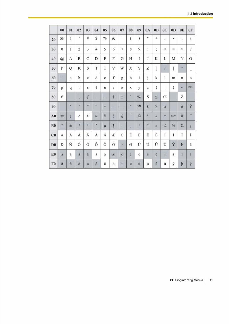
1.1.2 Entering Characters
The characters on a white background below can be used when storing a name, message, passwordor other text entry data using a PC. The available characters vary according to the model of PBX.
8/11/2019 TDA ProgrammingManual
http://slidepdf.com/reader/full/tda-programmingmanual 11/720
1.1 Introduction
PC Programming Manual 11
8/11/2019 TDA ProgrammingManual
http://slidepdf.com/reader/full/tda-programmingmanual 12/720
1.2 PC Programming
12 PC Programming Manual
1.2 PC Programming
1.2.1 Installing and Starting the Maintenance Console
System programming, diagnosis and administration can be performed with a PC using theMaintenance Console.This section briefly describes how to install and start the Maintenance Console when the PC and thePBX are connected by USB cable.
System RequirementsRequired Operating System
• Microsoft Windows XP or Windows Vista Business
Minimum Hardware Requirements
• CPU: 800 MHz Intel Celeron microprocessor
• HDD: 100 MB of available hard disk space
• RAM: 128 MB of available RAMRecommended Display Settings
• Screen resolution: XGA (1024 × 768)
• DPI setting: Normal size (96 DPI)
® ® ®
® ®
8/11/2019 TDA ProgrammingManual
http://slidepdf.com/reader/full/tda-programmingmanual 13/720
1.2 PC Programming
PC Programming Manual 13
Installing the Maintenance Console
Notes
• To install or uninstall the software on a PC running Windows XP Professional, you must belogged in as a user in either the "Administrators" or "Power Users" group.
• To install or uninstall the software on a PC running Windows Vista Business, you must be
logged in as a user in the "Administrators" group.• To connect the PC to the PBX via USB, the KX-TDA USB driver must be installed. Follow
the instructions of the wizard to install the KX-TDA USB driver. When the PBX is firstconnected to the PC via USB, you may be asked to select the appropriate USB driver.Browse for and select the KX-TDA USB driver that was installed previously.
Starting the Maintenance Console and Assigning the Basic Items (QuickSetup)
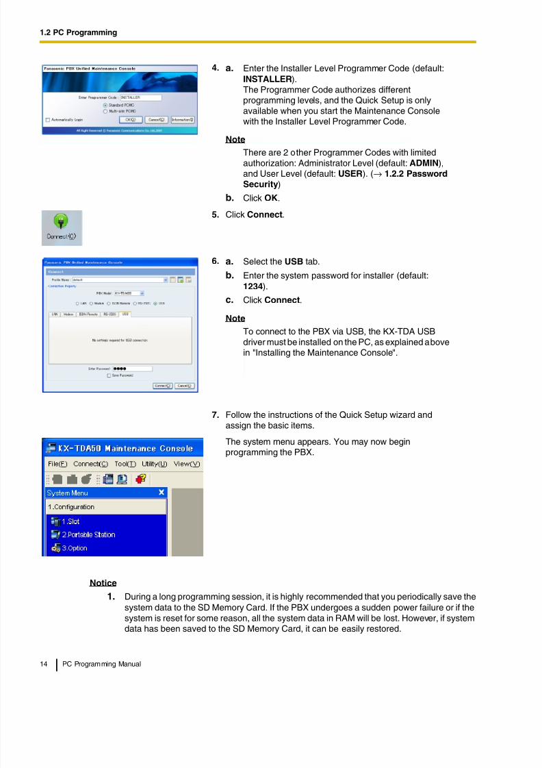
When you start the Maintenance Console with the Installer Level Programmer Code and connect tothe PBX for the first time after initialization (with the factory default setting), Quick Setup will launchautomatically. During Quick Setup, you will set up the following basic items:
• Date and Time of the PBX. The date and time set to the PC's clock will be used.
• System Password for installer for PC programming.
• Operator and manager settings. Operator extensions for all time modes (day/lunch/break/ night) can be assigned.
• Flexible Numbering plan to Type 1 or Type 2. If Type 1 (with ) is selected, " " must prefixall feature numbers (except access numbers) when an extension user wants to use a
feature.• Operator call and Idle Line Access/ARS numbers.
• Remote Maintenance Dial Number. Enter the complete telephone number of the PBX. Whennecessary, this number will be used to access the PBX from a remote location formaintenance purposes.
1. Copy the setup file of the Maintenance Console to your PC.
2. Double-click the setup file to run the installer.
3. Follow the on-screen instructions provided by theinstallation wizard.
1. Connect the PC to the PBX with a USB cable.
2. Start Maintenance Console from the Start menu.
3. "Information before programming" appears.
a. Carefully read this important additional information,
which includes updates to this and other manuals.b. Click OK to close this window.
8/11/2019 TDA ProgrammingManual
http://slidepdf.com/reader/full/tda-programmingmanual 14/720
1.2 PC Programming
14 PC Programming Manual
Notice
1. During a long programming session, it is highly recommended that you periodically save thesystem data to the SD Memory Card. If the PBX undergoes a sudden power failure or if thesystem is reset for some reason, all the system data in RAM will be lost. However, if systemdata has been saved to the SD Memory Card, it can be easily restored.
4. a. Enter the Installer Level Programmer Code (default:INSTALLER).The Programmer Code authorizes differentprogramming levels, and the Quick Setup is onlyavailable when you start the Maintenance Consolewith the Installer Level Programmer Code.
Note
There are 2 other Programmer Codes with limitedauthorization: Administrator Level (default: ADMIN),and User Level (default: USER). (→ 1.2.2 PasswordSecurity)
b. Click OK.
5. Click Connect.
6. a. Select the USB tab.
b. Enter the system password for installer (default:1234).
c. Click Connect.
Note
To connect to the PBX via USB, the KX-TDA USBdriver must be installed on the PC, as explained abovein "Installing the Maintenance Console".
7. Follow the instructions of the Quick Setup wizard andassign the basic items.
The system menu appears. You may now beginprogramming the PBX.
8/11/2019 TDA ProgrammingManual
http://slidepdf.com/reader/full/tda-programmingmanual 15/720
1.2 PC Programming
PC Programming Manual 15
To save the system data to the SD Memory Card, (1) click the "SD Memory Backup" iconbefore resetting the PBX or turning off the power, or (2) exit the Maintenance Console sothat the PBX automatically saves the system data.
2. The PC will not perform any shutdown operation, or enter the power-saving system standbymode while the Maintenance Console is connected to the PBX.To perform either of the operations above, first close the connection to the PBX.
CAUTION
Do not remove the SD Memory Card while power is supplied to the PBX. Doing so may causethe PBX to fail to start when you try to restart the system.
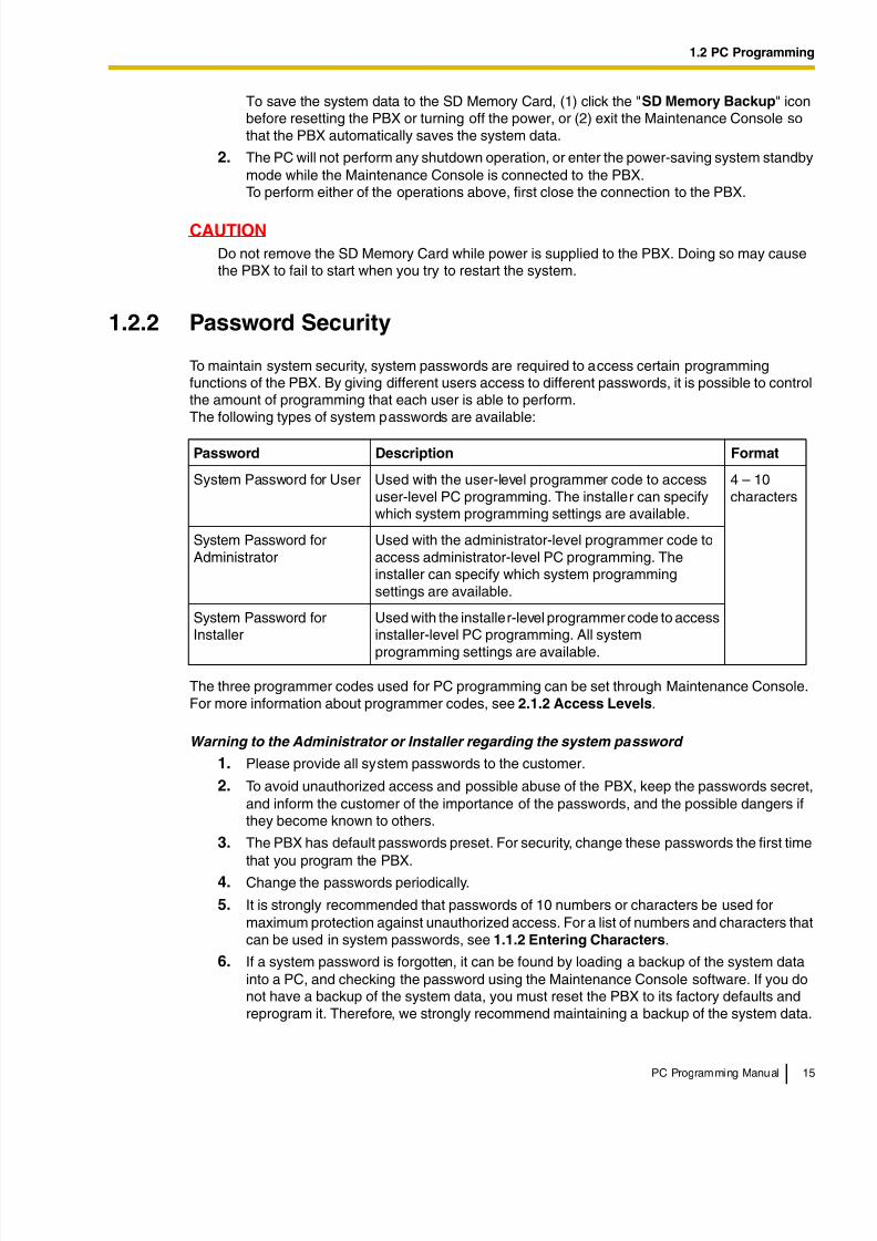
1.2.2 Password Security
To maintain system security, system passwords are required to access certain programmingfunctions of the PBX. By giving different users access to different passwords, it is possible to controlthe amount of programming that each user is able to perform.The following types of system passwords are available:
The three programmer codes used for PC programming can be set through Maintenance Console.For more information about programmer codes, see 2.1.2 Access Levels.
Warning to the Administrator or Installer regarding the system password
1. Please provide all system passwords to the customer.
2. To avoid unauthorized access and possible abuse of the PBX, keep the passwords secret,and inform the customer of the importance of the passwords, and the possible dangers ifthey become known to others.
3. The PBX has default passwords preset. For security, change these passwords the first timethat you program the PBX.
4. Change the passwords periodically.
5. It is strongly recommended that passwords of 10 numbers or characters be used formaximum protection against unauthorized access. For a list of numbers and characters thatcan be used in system passwords, see 1.1.2 Entering Characters.
6. If a system password is forgotten, it can be found by loading a backup of the system datainto a PC, and checking the password using the Maintenance Console software. If you donot have a backup of the system data, you must reset the PBX to its factory defaults andreprogram it. Therefore, we strongly recommend maintaining a backup of the system data.
Password Description Format
System Password for User Used with the user-level programmer code to accessuser-level PC programming. The installer can specifywhich system programming settings are available.
4 – 10characters
System Password forAdministrator
Used with the administrator-level programmer code toaccess administrator-level PC programming. Theinstaller can specify which system programmingsettings are available.
System Password forInstaller
Used with the installer-level programmer code to accessinstaller-level PC programming. All system
programming settings are available.
8/11/2019 TDA ProgrammingManual
http://slidepdf.com/reader/full/tda-programmingmanual 16/720
1.2 PC Programming
16 PC Programming Manual
For more information on how to back up the system data, refer to the on-line help of theMaintenance Console.However, as system passwords can be extracted from backup copies of the system data file,do not allow unauthorized access to these files.
8/11/2019 TDA ProgrammingManual
http://slidepdf.com/reader/full/tda-programmingmanual 17/720
PC Programming Manual 17
Section 2
Maintenance Console Operating Instructions
This section serves as reference operating instructions when
using the Maintenance Console software to program the PBX.
8/11/2019 TDA ProgrammingManual
http://slidepdf.com/reader/full/tda-programmingmanual 18/720
2.1 Introduction
18 PC Programming Manual
2.1 Introduction
2.1.1 Starting Maintenance Console and Software Modes
Every time Maintenance Console is started, a dialog box will appear. From here, you can enter anyof the 2 available software modes.
• Batch mode
Batch mode allows you to create new system data files, and make modifications to systemdata files stored on your PC, without being connected to the PBX. When you connect to thePBX, the modified data will be uploaded at one time.
• Interactive mode
Interactive mode allows you to directly modify the system data and settings stored in thePBX's memory from a PC that is connected to the PBX. This mode displays the system datathat is currently being used by the PBX, rather than the system data stored on the SDmemory card. Data can be modified and results displayed in real time.
To start Maintenance Console in Batch mode1. Enter the relevant programmer code.
2. Click OK.
The start menu will appear.
3. Select an option.
• Select New to create a new system data file.
• Select Open to open an existing system data file.
To start Maintenance Console in Interactive mode
1. Enter the relevant programmer code.
2. Click OK.The start menu will appear.
3. Click Connect.
Connection options will be displayed.
• Select a Profile Name if you want to use a pre-saved profile. This option is only availablewhen one or more profiles have been previously stored.
a. Select the profile to use from the drop-down list.
b. If the system password for the PBX has not been stored with the profile, enter it.
If the system password has been stored with the selected profile, it does not need to beentered.
• To enter the parameters manually, select the PBX Model and select the method ofconnecting to the PBX.
a. Specify the settings as required. For more details, see the tables below.
b. Enter the system password for the PBX.
4. Click Connect.
Maintenance Console will start, and automatically connect to the PBX. If this is the first time thatMaintenance Console has connected to the PBX, and the date and time of the PBX have not yetbeen set, the Quick Setup wizard will run. For more details, see Starting the MaintenanceConsole and Assigning the Basic Items (Quick Setup).
8/11/2019 TDA ProgrammingManual
http://slidepdf.com/reader/full/tda-programmingmanual 19/720
2.1 Introduction
PC Programming Manual 19
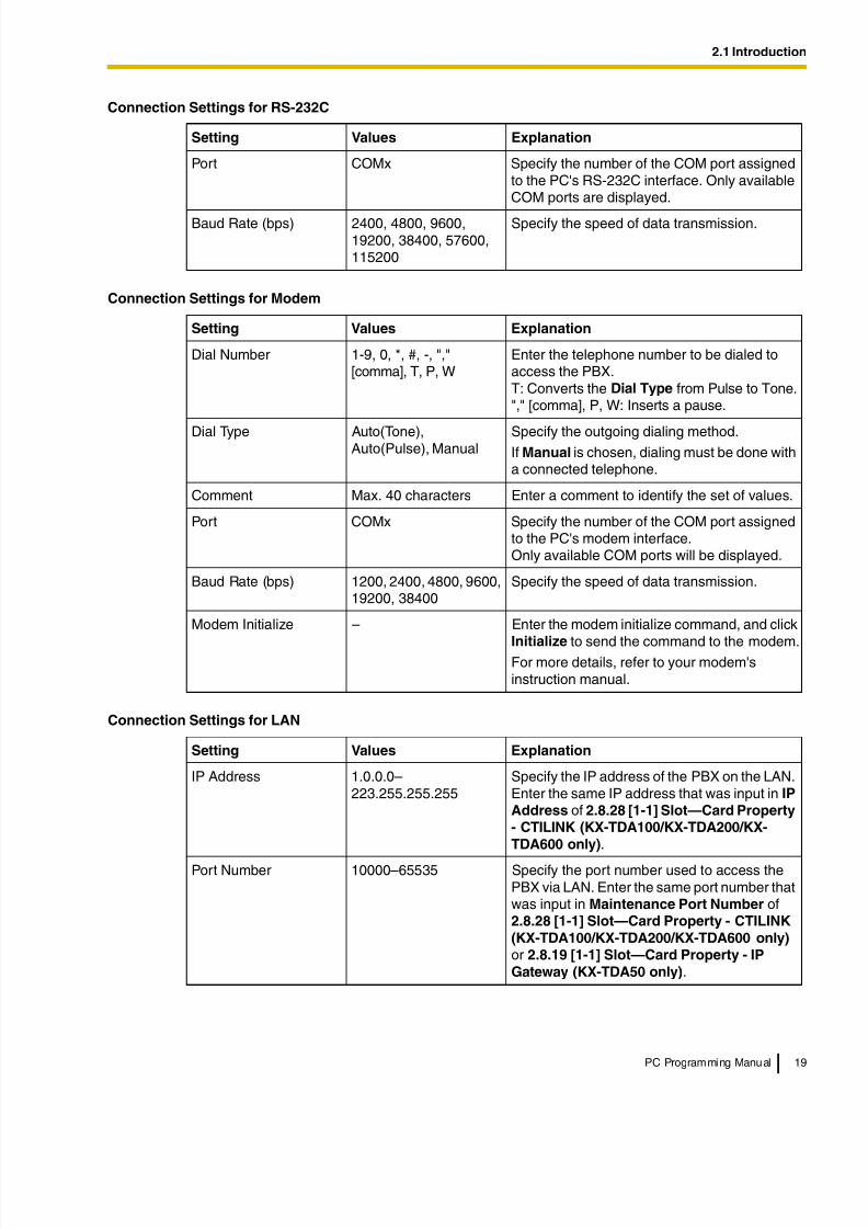
Connection Settings for RS-232C
Setting Values Explanation
Port COMx Specify the number of the COM port assignedto the PC's RS-232C interface. Only availableCOM ports are displayed.
Baud Rate (bps) 2400, 4800, 9600,19200, 38400, 57600,115200
Specify the speed of data transmission.
Connection Settings for Modem
Setting Values Explanation
Dial Number 1-9, 0, *, #, -, ","[comma], T, P, W
Enter the telephone number to be dialed toaccess the PBX.T: Converts the Dial Type from Pulse to Tone."," [comma], P, W: Inserts a pause.
Dial Type Auto(Tone),Auto(Pulse), Manual
Specify the outgoing dialing method.If Manual is chosen, dialing must be done witha connected telephone.
Comment Max. 40 characters Enter a comment to identify the set of values.
Port COMx Specify the number of the COM port assignedto the PC's modem interface.Only available COM ports will be displayed.
Baud Rate (bps) 1200, 2400, 4800, 9600,19200, 38400
Specify the speed of data transmission.
Modem Initialize – Enter the modem initialize command, and click
Initialize to send the command to the modem.For more details, refer to your modem'sinstruction manual.
Connection Settings for LAN
Setting Values Explanation
IP Address 1.0.0.0–223.255.255.255
Specify the IP address of the PBX on the LAN.Enter the same IP address that was input in IP
Address of 2.8.28 [1-1] Slot—Card Property- CTILINK (KX-TDA100/KX-TDA200/KX-
TDA600 only).
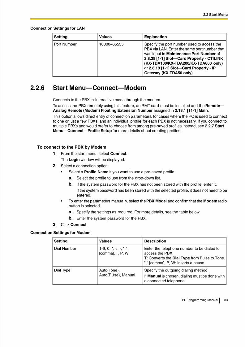
Port Number 10000–65535 Specify the port number used to access thePBX via LAN. Enter the same port number thatwas input in Maintenance Port Number of2.8.28 [1-1] Slot—Card Property - CTILINK
(KX-TDA100/KX-TDA200/KX-TDA600 only) or 2.8.19 [1-1] Slot—Card Property - IP
Gateway (KX-TDA50 only).
8/11/2019 TDA ProgrammingManual
http://slidepdf.com/reader/full/tda-programmingmanual 20/720
2.1 Introduction
20 PC Programming Manual
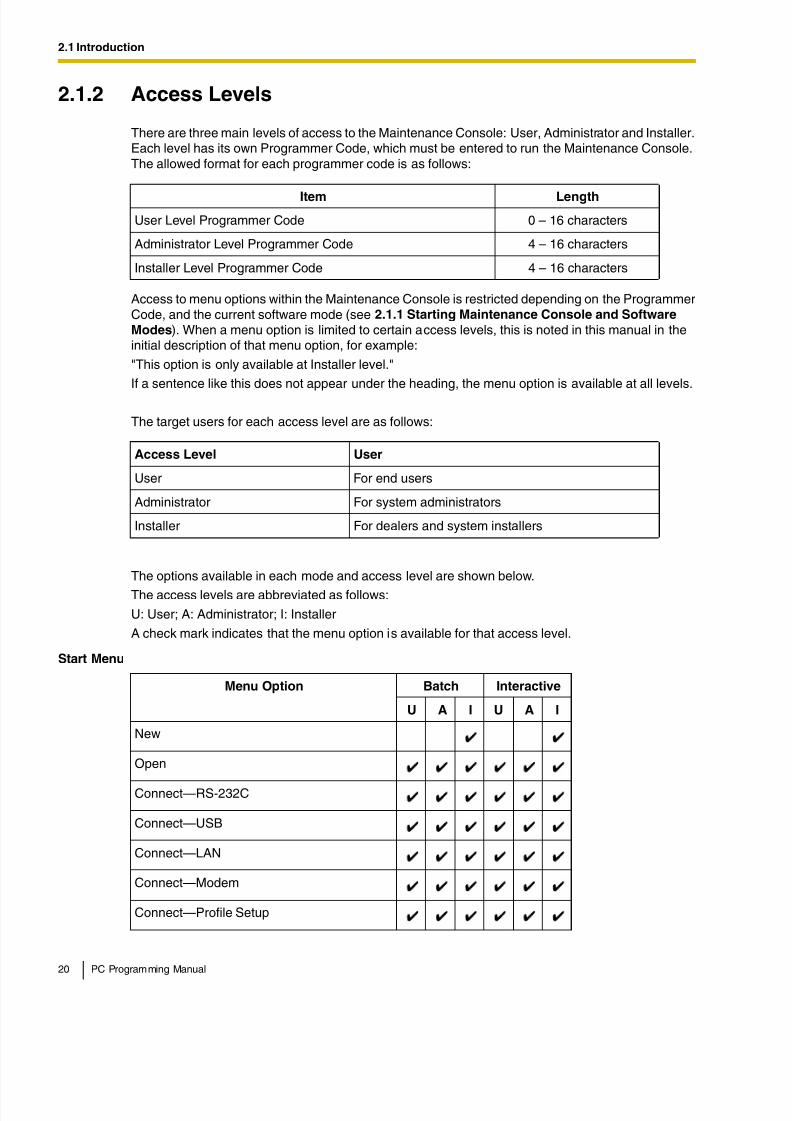
2.1.2 Access Levels
There are three main levels of access to the Maintenance Console: User, Administrator and Installer.Each level has its own Programmer Code, which must be entered to run the Maintenance Console.The allowed format for each programmer code is as follows:
Access to menu options within the Maintenance Console is restricted depending on the ProgrammerCode, and the current software mode (see 2.1.1 Starting Maintenance Console and Software
Modes). When a menu option is limited to certain access levels, this is noted in this manual in theinitial description of that menu option, for example:
"This option is only available at Installer level."
If a sentence like this does not appear under the heading, the menu option is available at all levels.
The target users for each access level are as follows:
The options available in each mode and access level are shown below.
The access levels are abbreviated as follows:
U: User; A: Administrator; I: Installer
A check mark indicates that the menu option is available for that access level.
Item Length
User Level Programmer Code 0 – 16 characters
Administrator Level Programmer Code 4 – 16 characters
Installer Level Programmer Code 4 – 16 characters
Access Level User
User For end users
Administrator For system administrators
Installer For dealers and system installers
Start Menu
Menu Option Batch Interactive
U A I U A I
New
Open
Connect—RS-232C
Connect—USB
Connect—LAN
Connect—Modem
Connect—Profile Setup
8/11/2019 TDA ProgrammingManual
http://slidepdf.com/reader/full/tda-programmingmanual 21/720
2.1 Introduction
PC Programming Manual 21
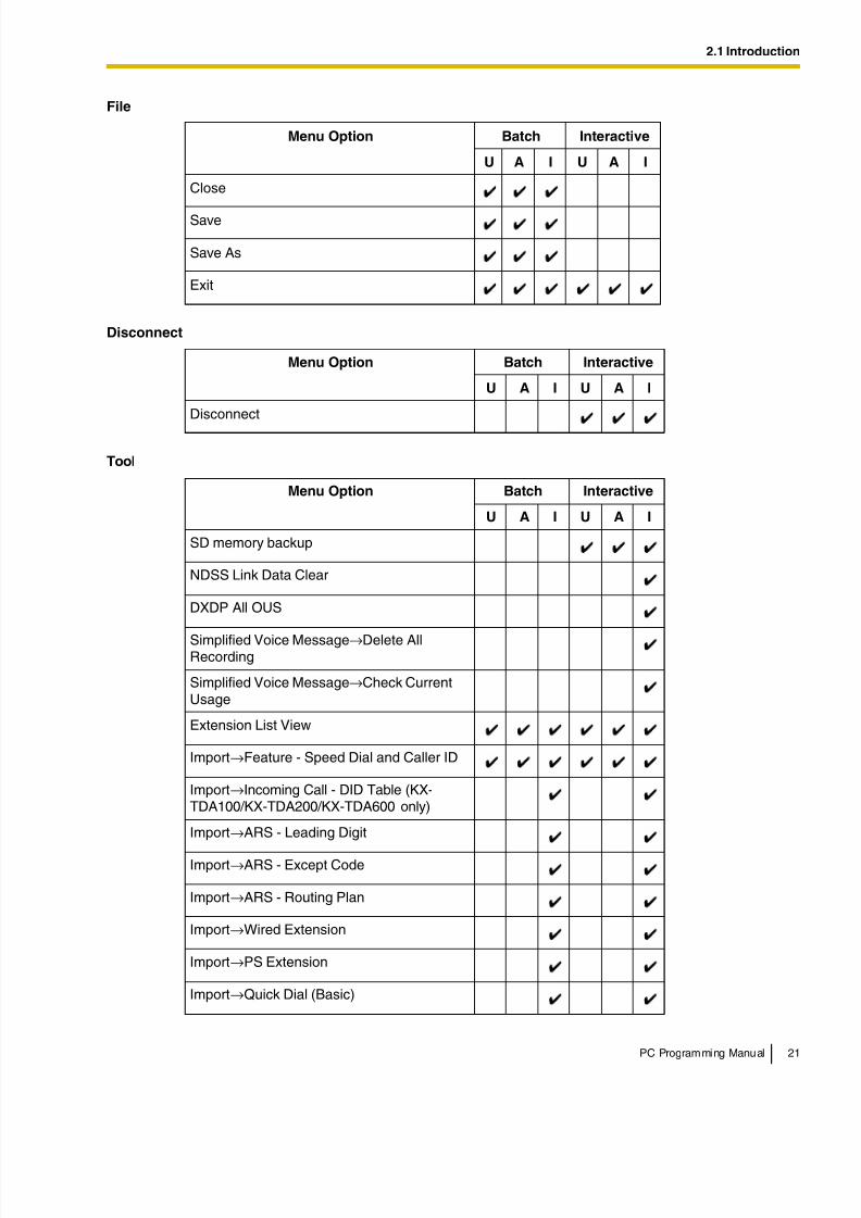
File
Menu Option Batch Interactive
U A I U A I
Close
Save
Save As
Exit
Disconnect
Menu Option Batch Interactive
U A I U A I
Disconnect
Tool
Menu Option Batch Interactive
U A I U A I
SD memory backup
NDSS Link Data Clear
DXDP All OUS
Simplified Voice Message→Delete AllRecording
Simplified Voice Message→Check CurrentUsage
Extension List View
Import→Feature - Speed Dial and Caller ID
Import→Incoming Call - DID Table (KX-TDA100/KX-TDA200/KX-TDA600 only)
Import→ARS - Leading Digit
Import→ARS - Except Code
Import→ARS - Routing Plan
Import→Wired Extension
Import→PS Extension
Import→Quick Dial (Basic)
8/11/2019 TDA ProgrammingManual
http://slidepdf.com/reader/full/tda-programmingmanual 22/720
2.1 Introduction
22 PC Programming Manual
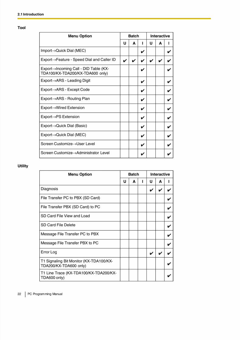
Import→Quick Dial (MEC)
Export→Feature - Speed Dial and Caller ID
Export→Incoming Call - DID Table (KX-TDA100/KX-TDA200/KX-TDA600 only)
Export→ARS - Leading Digit
Export→ARS - Except Code
Export→ARS - Routing Plan
Export→Wired Extension
Export→PS Extension
Export→Quick Dial (Basic)
Export→Quick Dial (MEC)
Screen Customize→User Level
Screen Customize→Administrator Level
Utility
Menu Option Batch Interactive
U A I U A I
Diagnosis
File Transfer PC to PBX (SD Card)
File Transfer PBX (SD Card) to PC
SD Card File View and Load
SD Card File Delete
Message File Transfer PC to PBX
Message File Transfer PBX to PC
Error Log
T1 Signaling Bit Monitor (KX-TDA100/KX-TDA200/KX-TDA600 only)
T1 Line Trace (KX-TDA100/KX-TDA200/KX-TDA600 only)
Tool
Menu Option Batch Interactive
U A I U A I
8/11/2019 TDA ProgrammingManual
http://slidepdf.com/reader/full/tda-programmingmanual 23/720
2.1 Introduction
PC Programming Manual 23
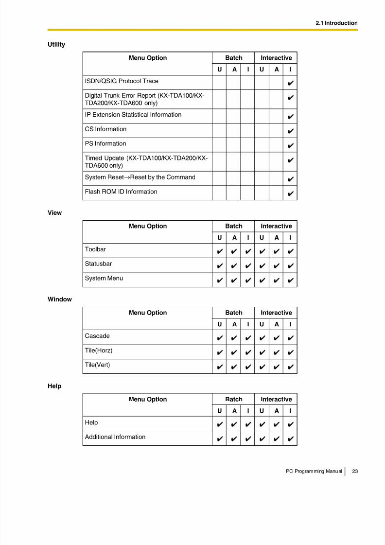
ISDN/QSIG Protocol Trace
Digital Trunk Error Report (KX-TDA100/KX-TDA200/KX-TDA600 only)
IP Extension Statistical Information
CS Information
PS Information
Timed Update (KX-TDA100/KX-TDA200/KX-TDA600 only)
System Reset→Reset by the Command
Flash ROM ID Information
View
Menu Option Batch Interactive
U A I U A I
Toolbar
Statusbar
System Menu
Window
Menu Option Batch Interactive
U A I U A I
Cascade
Tile(Horz)
Tile(Vert)
Help
Menu Option Batch Interactive
U A I U A I
Help
Additional Information
Utility
Menu Option Batch Interactive
U A I U A I
8/11/2019 TDA ProgrammingManual
http://slidepdf.com/reader/full/tda-programmingmanual 24/720
2.1 Introduction
24 PC Programming Manual
2.1.3 Software Interface
This section explains the functions of the various elements of the software interface.
Main WindowThe window of the Maintenance Console software is divided into several areas, as shown below:
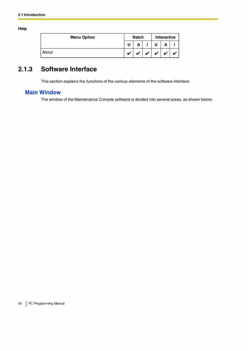
About
Help
Menu Option Batch Interactive
U A I U A I
8/11/2019 TDA ProgrammingManual
http://slidepdf.com/reader/full/tda-programmingmanual 25/720
2.1 Introduction
PC Programming Manual 25
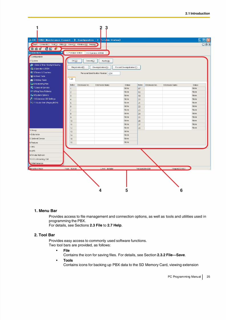
1. Menu Bar
Provides access to file management and connection options, as well as tools and utilities used inprogramming the PBX.
For details, see Sections 2.3 File to 2.7 Help.
2. Tool Bar
Provides easy access to commonly used software functions.Two tool bars are provided, as follows:
• File
Contains the icon for saving files. For details, see Section 2.3.2 File—Save.
• Tools
Contains icons for backing up PBX data to the SD Memory Card, viewing extension
1 2 3
4 5 6
8/11/2019 TDA ProgrammingManual
http://slidepdf.com/reader/full/tda-programmingmanual 26/720
8/11/2019 TDA ProgrammingManual
http://slidepdf.com/reader/full/tda-programmingmanual 27/720
2.1 Introduction
PC Programming Manual 27
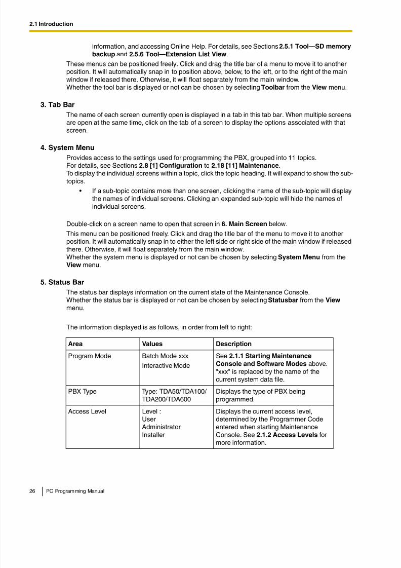
6. Main Screen
Displays the screens selected from 4. System Menu above.For details, see Sections 2.8 [1] Configuration to 2.18 [11] Maintenance.
Standard Buttons and ElementsThere are several standard buttons that are displayed on many screens within the MaintenanceConsole.
The standard buttons are as follows:
In addition, many screens within the software display a small open folder icon ( ) beside lists ofsetting items. Clicking this icon will collapse part of the list, allowing other items to be displayed. The
icon will change to a closed folder ( ).Clicking the closed folder icon will expand the list again.
2.1.4 Card Status
Certain tools, utilities and settings require that the target card be set to out-of-service (OUS) or in-service (INS) status before the operation is carried out. Where required, this is noted in thedescription of each item. Card status changes can only be performed when the software is inInteractive mode (see 2.1.1 Starting Maintenance Console and Software Modes).
• "In service" means that the card is installed correctly in the PBX, and is capable of beingused normally.
PBX System DataVersion
Versionxxx-xxx Displays the version number of thesystem software installed to the PBX.
The first 3 digits are the version number,and the last 3 digits are the revisionnumber.
PBX Region Code Regionxxx-xxx Displays the region code assigned to thePBX and Maintenance Console.
The first 3 digits represent the regioncode assigned to the PBX, and the last 3digits represent the region codeassigned to the Maintenance Console.
Button Function
OK Implements changes and closes the current screen.
Cancel Abandons changes and returns to the previous screen.
Close Keeps any changes implemented, and closes the current screen.
Apply Implements changes and remains on the same screen.
Refresh Implements changes, updates displayed data, and remains on thecurrent screen.
Help Displays the relevant help topic for the current screen.
Area Values Description
8/11/2019 TDA ProgrammingManual
http://slidepdf.com/reader/full/tda-programmingmanual 28/720
2.1 Introduction
28 PC Programming Manual
• "Out of service" means that the card is installed correctly in the PBX, but has beentemporarily removed from use. This allows settings to be modified or software to beupgraded.
• "Fault" means that the card is not installed in the PBX correctly, or is not functioning correctly.For more information, see the Installation Manual.
For details about how to change the status of a card, see To change the status (INS/OUS) of a card
(Interactive mode only) on screen 2.8.1 [1-1] Slot.
2.1.5 Display Options
The View and Window menus provide options to control the display of items within the MaintenanceConsole.
• View
– Toolbar: Displays or hides the tool bar of commonly used buttons.
– Statusbar: Displays or hides the bar at the bottom of the Maintenance Console window.
– System Menu: Displays or hides the menu of PBX setting screens.
• Window– Cascade: When multiple data screens are open, displays all open screens overlapped, with
the title bars visible.
– Tile(Horz): When multiple data screens are open, displays all open screens side by side.
– Tile(Vert): When multiple data screens are open, displays all open screens vertically.
2.1.6 Extension Number Setting
Many screens within the Maintenance Console software allow you to select extensions as part ofprogramming various features (for example, as members of a group). These screens use a standardwindow to make selecting multiple extensions easy, accessed by clicking a button. This section
explains how to use this Extension Number Setting window.
To select multiple extension numbers, select the type of extension to display, highlight the extensionsyou wish to add, then click the Add button. When finished, click OK. Data for the selected extensionswill be added to the first free spaces on the original screen.
Extension Type
Selects the types of extension numbers to display in Extension Numbers & Names List. Multipleitems can be selected. Items that are not available are shown with a grey checkbox.
Default
None selected.
Value Range
Wired Extension, Portable Station, VM Group(DPT), VM Group(DTMF), ICD Group, PS Ring Group,OGM(DISA), External Pager, Analog MODEM
8/11/2019 TDA ProgrammingManual
http://slidepdf.com/reader/full/tda-programmingmanual 29/720
2.1 Introduction
PC Programming Manual 29
Extension Numbers & Names List
Displays all available extensions of the types selected in Extension Type, and names. Click entriesto select them, and click the Add button when finished, to add the selected extensions. To deselectan entry, click it again.
Default
Available extensions.
Value Range
Matching extensions
Available Column
Specifies which fields in the original form to add extension data to. For example, if both extensionnumbers and names can be entered in the original form, it is possible to specify that extension namedata not be transferred, by deselecting that field here.To select or deselect a field, click its name.
Default
First available field
Value Range
Available fields
Selected Extension List
Displays the extensions that have been selected to be added to member data. To remove anextension from this list, click it to select it and click Delete.
Default
Not stored.
Value Range
Selected extensions

8/11/2019 TDA ProgrammingManual
http://slidepdf.com/reader/full/tda-programmingmanual 30/720

8/11/2019 TDA ProgrammingManual
http://slidepdf.com/reader/full/tda-programmingmanual 31/720
2.2 Start Menu
PC Programming Manual 31
Enter a name for the new converted system file.
• Click No to open the file as it is.
2.2.3 Start Menu—Connect—RS-232C
Connects to the PBX in Interactive mode through the serial RS-232C interface of the PBX.This option allows direct entry of connection parameters, for cases where the PC is used to connectto one or just a few PBXs, and an individual profile for each PBX is not necessary. If you connect tomultiple PBXs and would prefer to choose from among pre-saved profiles instead, see 2.2.7 Start
Menu—Connect—Profile Setup for more details about creating profiles.
To connect to the PBX by RS-232C
1. From the start menu, select Connect.
The Login window will be displayed.
2. Select a connection option.
• Select a Profile Name if you want to use a pre-saved profile. This option is only availablewhen one or more profiles have been previously stored.
a. Select the profile to use from the drop-down list.
b. If the system password for the PBX has not been stored with the profile, enter it.
If the system password has been stored with the selected profile, it does not need to beentered.
• To enter the parameters manually, select the PBX Model and confirm that the RS-232C radio button is selected.
a. Specify the settings as required. For more details, see the table below.
b. Enter the system password for the PBX.
3. Click Connect.
2.2.4 Start Menu—Connect—USB
Connects to the PBX in Interactive mode through the USB port on the PBX, or a USB port (USBModule) attached to a DPT.
To connect to the PBX by USB
1. From the start menu, select Connect.
The Login window will be displayed.
Connection Settings for RS-232C
Setting Values Explanation
Port COMx Specify the number of the COM port assignedto the PC's RS-232C interface. Only availableCOM ports are displayed.
Baud Rate (bps) 2400, 4800, 9600,19200, 38400, 57600,115200
Specify the speed of data transmission.
8/11/2019 TDA ProgrammingManual
http://slidepdf.com/reader/full/tda-programmingmanual 32/720
2.2 Start Menu
32 PC Programming Manual
2. Select a connection option.
• Select a Profile Name if you want to use a pre-saved profile.
a. Select the profile to use from the drop-down list.
b. If the system password for the PBX has not been stored with the profile, enter it.
If the system password has been stored with the selected profile, it does not need to beentered.
• To enter the parameters manually, select the PBX Model and confirm that the USB radiobutton is selected.
a. Enter the system password for the PBX.
3. Click Connect.
2.2.5 Start Menu—Connect—LAN
Connects to the PBX in Interactive mode through the Local Area Network interface of the PBX.
A CTI-LINK card (KX-TDA100/KX-TDA200/KX-TDA600) or IP-GW4 card (KX-TDA50) must beinstalled and the IP address of the PBX set to use this feature. For more details, see 2.8.28 [1-1]Slot—Card Property - CTILINK (KX-TDA100/KX-TDA200/KX-TDA600 only) and 2.8.19 [1-1]
Slot—Card Property - IP Gateway (KX-TDA50 only).
This option allows direct entry of connection parameters, for cases where the PC is used to connectto one or just a few PBXs, and an individual profile for each PBX is not necessary. If you connect tomultiple PBXs and would prefer to choose from among pre-saved profiles instead, see 2.2.7 Start
Menu—Connect—Profile Setup for more details about creating profiles.
To connect to the PBX by LAN
1. From the start menu, select Connect.
The Login window will be displayed.
2. Select a connection option.
• Select a Profile Name if you want to use a pre-saved profile.
a. Select the profile to use from the drop-down list.
b. If the system password for the PBX has not been stored with the profile, enter it.
If the system password has been stored with the selected profile, it does not need to beentered.
• To enter the parameters manually, select the PBX Model and confirm that the LAN radiobutton is selected.
a. Specify the connection parameters as required. For more details, see the table below.
b. Enter the system password for the PBX.
3. Click Connect.
Connection Settings for LAN
Setting Values Explanation
IP Address 1.0.0.0–223.255.255.255
Specify the IP address of the PBX on the LAN.Enter the same IP address that was input in IPAddress of 2.8.28 [1-1] Slot—Card Property
- CTILINK (KX-TDA100/KX-TDA200/KX-TDA600 only).
8/11/2019 TDA ProgrammingManual
http://slidepdf.com/reader/full/tda-programmingmanual 33/720
2.2 Start Menu
PC Programming Manual 33
2.2.6 Start Menu—Connect—Modem
Connects to the PBX in Interactive mode through the modem.
To access the PBX remotely using this feature, an RMT card must be installed and the Remote—Analog Remote (Modem) Floating Extension Number assigned in 2.18.1 [11-1] Main.
This option allows direct entry of connection parameters, for cases where the PC is used to connect
to one or just a few PBXs, and an individual profile for each PBX is not necessary. If you connect tomultiple PBXs and would prefer to choose from among pre-saved profiles instead, see 2.2.7 StartMenu—Connect—Profile Setup for more details about creating profiles.
To connect to the PBX by Modem
1. From the start menu, select Connect.
The Login window will be displayed.
2. Select a connection option.
• Select a Profile Name if you want to use a pre-saved profile.
a. Select the profile to use from the drop-down list.
b. If the system password for the PBX has not been stored with the profile, enter it.
If the system password has been stored with the selected profile, it does not need to beentered.
• To enter the parameters manually, select the PBX Model and confirm that the Modem radiobutton is selected.
a. Specify the settings as required. For more details, see the table below.
b. Enter the system password for the PBX.
3. Click Connect.
Port Number 10000–65535 Specify the port number used to access thePBX via LAN. Enter the same port number thatwas input in Maintenance Port Number of2.8.28 [1-1] Slot—Card Property - CTILINK
(KX-TDA100/KX-TDA200/KX-TDA600 only) or 2.8.19 [1-1] Slot—Card Property - IP
Gateway (KX-TDA50 only).
Connection Settings for Modem
Setting Values DescriptionDial Number 1-9, 0, *, #, -, ","
[comma], T, P, WEnter the telephone number to be dialed toaccess the PBX.T: Converts the Dial Type from Pulse to Tone."," [comma], P, W: Inserts a pause.
Dial Type Auto(Tone),Auto(Pulse), Manual
Specify the outgoing dialing method.
If Manual is chosen, dialing must be done witha connected telephone.
Connection Settings for LAN
Setting Values Explanation
8/11/2019 TDA ProgrammingManual
http://slidepdf.com/reader/full/tda-programmingmanual 34/720
2.2 Start Menu
34 PC Programming Manual
2.2.7 Start Menu—Connect—Profile Setup
Profiles are useful when one PC is used to connect to multiple PBXs. Rather than manually adjustingthe connection settings each time a different PBX is accessed, it is possible to store the connectionsettings for several PBXs. Then, when you wish to connect to a specific PBX, you can simply choosethat PBX's profile from the list.
Note
When reinstalling or upgrading the Maintenance Console, it is possible to create a backup of allprofiles. This allows you to use the original connection settings with the new MaintenanceConsole.
The functions of the buttons on this screen are as follows:
Comment Max. 40 characters Enter a comment to identify the set of values.
Port COMx Specify the number of the COM port assignedto the PC's modem interface.
Only available COM ports will be displayed.
Baud Rate (bps) 1200, 2400, 4800, 9600,19200, 38400
Specify the speed of data transmission.
Modem Initialize – Enter the modem initialize command, and clickInitialize to send the command to the modem.
For more details, refer to your modem'sinstruction manual.
Button Function
Save current profile Overwrites the previous settings with the current settings when a profilealready exists. A confirmation message will be displayed.
Save as new profile Saves the current settings as a new profile. A Profile Name is required.
Delete profile When an existing profile is selected, deletes that profile. A confirmationmessage will be displayed.
Connection Settings for Modem
Setting Values Description
8/11/2019 TDA ProgrammingManual
http://slidepdf.com/reader/full/tda-programmingmanual 35/720
2.3 File
PC Programming Manual 35
2.3 File
2.3.1 File—Close
Closes the system data file that is currently being modified, and returns to the start menu.
To close a system data file
• From the File menu, select Close.
If the system data file has not been saved, a warning message will be displayed, giving you theoption to save the file.
• Click Yes to save the file.
• Click No to abandon the changes.
2.3.2 File—Save
Overwrites the previously saved system data file with the system data currently being modified inBatch mode.
To upload a file saved here to the SD memory card installed in the PBX, see 2.6.2 Utility—FileTransfer PC to PBX (SD Card).
To save a system data file
• From the File menu, select Save.
If the data has never been saved, the Save dialog box will be displayed. For more details, see2.3.3 File—Save As.
2.3.3 File—Save As
Saves the system data file being modified in Batch mode with the name chosen by the user.
To upload a file saved here to the SD memory card installed in the PBX, see 2.6.2 Utility—File
Transfer PC to PBX (SD Card).
To save a system data file with a new name
1. From the File menu, select Save As.
2. Navigate to the folder in which you want to save the file.
3. Enter a file name, or select a file to overwrite.
4. Click Save.
If choosing to overwrite another file, a warning message will be displayed.
• Click Yes to overwrite.
• Click No to return to the previous screen.
2.3.4 File—Exit
Closes the Maintenance Console.
8/11/2019 TDA ProgrammingManual
http://slidepdf.com/reader/full/tda-programmingmanual 36/720
2.3 File
36 PC Programming Manual
To exit the Maintenance Console
• From the File menu, select Exit.
If the system data file being modified has not been saved, a warning message will be displayed,giving you the option to save the file.
• Click Yes to save the file.
• Click No to abandon the changes.
8/11/2019 TDA ProgrammingManual
http://slidepdf.com/reader/full/tda-programmingmanual 37/720
2.4 Disconnect
PC Programming Manual 37
2.4 Disconnect
2.4.1 Disconnect—Disconnect
Closes the connection between the Maintenance Console and the PBX. When this option is chosen,system data is automatically backed up from the PBX to the SD memory card (see 2.5.1 Tool—SDmemory backup).
To disconnect
1. From the Disconnect menu, select Disconnect.A confirmation message will be displayed.
2. Click Yes.
8/11/2019 TDA ProgrammingManual
http://slidepdf.com/reader/full/tda-programmingmanual 38/720
2.5 Tool
38 PC Programming Manual
2.5 Tool
2.5.1 Tool—SD memory backup
Saves system data from the PBX to the SD memory card. Backup begins as soon as this option ischosen.
To back up system data
• From the Tool menu, select SD memory backup.
2.5.2 Tool—NDSS Link Data Clear
Clears NDSS Link Data stored in the connected PBX. While this tool clears both monitor extensionand monitored extension data, it only clears it at the connected PBX. To clear this data at other PBXsin the network, it is necessary to run this tool at those PBXs.
To clear the NDSS Link Data
• From the Tool menu, select NDSS Link Data Clear.
A confirmation screen will be displayed.
• Click OK to clear the data.
• Click Cancel to keep the data, and close the screen.
2.5.3 Tool—DXDP All OUS
Sets the status of all DXDP/XDP extension ports to "OUS" simultaneously.
To set all DXDP/XDP ports to OUS.
1. From the Tool menu, select DXDP All OUS.
2. Click OK.
2.5.4 Tool—Simplified Voice Message—Delete All Recording
Deletes all voice messages recorded to SVM/ESVM cards installed in the PBX.
To delete voice messages
1. From the Tool menu, point to Simplified Voice Message and select Delete All Recordings.
2. Select the card from which to delete messages.
3. Click OK.
8/11/2019 TDA ProgrammingManual
http://slidepdf.com/reader/full/tda-programmingmanual 39/720
2.5 Tool
PC Programming Manual 39
2.5.5 Tool—Simplified Voice Message—Check Current Usage
Displays information on the voice messages stored in SVM/ESVM cards installed in the PBX. Foreach message, the type of message and the associated extension are displayed.
To view SVM message status
• From the Tool menu, point to Simplified Voice Message and select Check Current Usage.
2.5.6 Tool—Extension List View
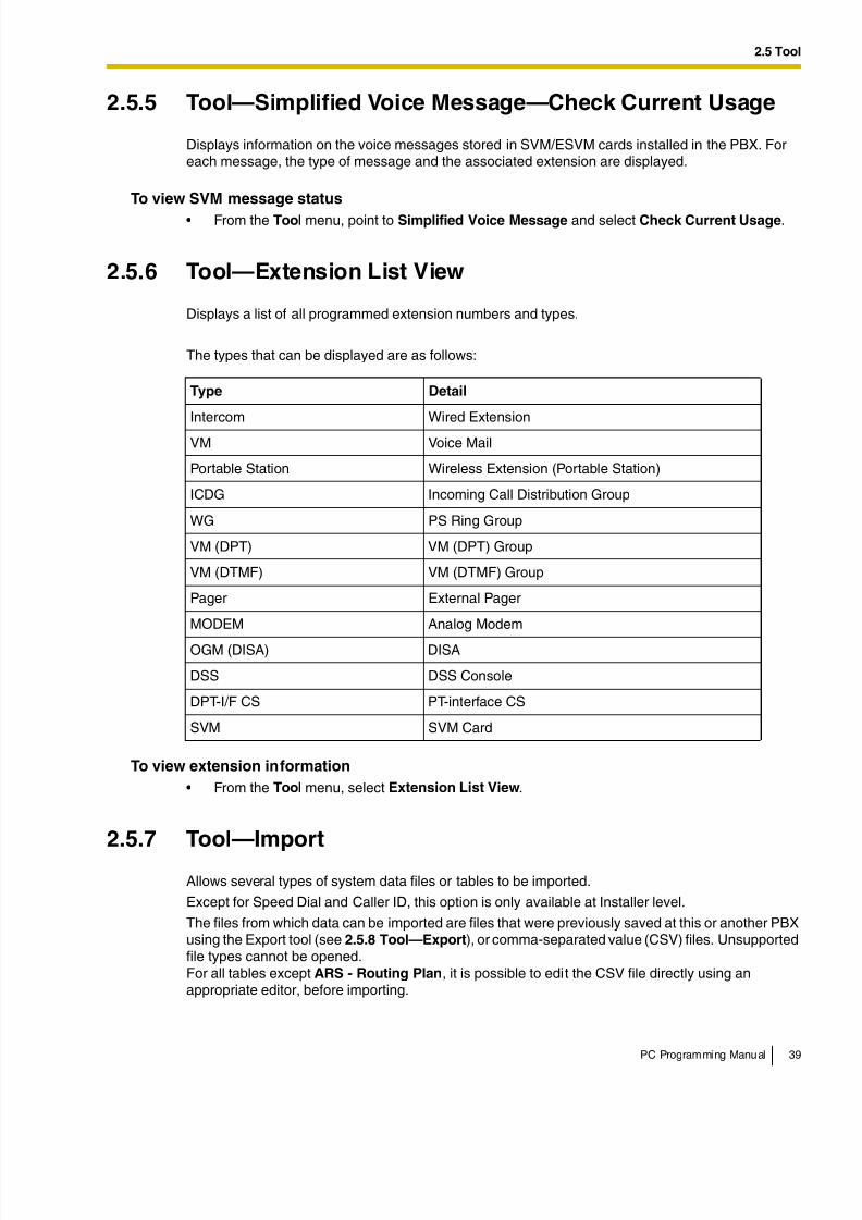
Displays a list of all programmed extension numbers and types.
The types that can be displayed are as follows:
To view extension information
• From the Tool menu, select Extension List View.
2.5.7 Tool—Import
Allows several types of system data files or tables to be imported.
Except for Speed Dial and Caller ID, this option is only available at Installer level.
The files from which data can be imported are files that were previously saved at this or another PBXusing the Export tool (see 2.5.8 Tool—Export), or comma-separated value (CSV) files. Unsupportedfile types cannot be opened.For all tables except ARS - Routing Plan, it is possible to edit the CSV file directly using anappropriate editor, before importing.
Type Detail
Intercom Wired Extension
VM Voice Mail
Portable Station Wireless Extension (Portable Station)
ICDG Incoming Call Distribution Group
WG PS Ring Group
VM (DPT) VM (DPT) Group
VM (DTMF) VM (DTMF) Group
Pager External Pager
MODEM Analog Modem
OGM (DISA) DISA
DSS DSS Console
DPT-I/F CS PT-interface CS
SVM SVM Card
8/11/2019 TDA ProgrammingManual
http://slidepdf.com/reader/full/tda-programmingmanual 40/720
2.5 Tool
40 PC Programming Manual
The types of data that can be imported using this tool, and the matching destination fields, are asfollows:
Related programming: 2.13.1 [6-1] System Speed Dial
Related programming: 2.17.3 [10-3] DID Table (KX-TDA100/KX-TDA200/KX-TDA600 only)
Feature - Speed Dial and Caller ID
Data Type Import Destination
System Speed Dialing
Number
Location
Name Name
CO Line Access Number +Telephone Number
Dial
CLI Destination CLI Destination
Incoming Call - DID Table (KX-TDA100/KX-TDA200/KX-TDA600 only)
Data Type Import DestinationLocation Location
DID Number Dial In Number
DID Name Dial In Name
DID Destination-Day Destination-Day
DID Destination-Lunch Destination-Lunch
DID Destination-Break Destination-Break
DID Destination-Night Destination-Night
Tenant Number Tenant Number
VM Trunk Group No. Group Number for VPSanswer
CLI Ring for DID-Day CLI Ring - Day
CLI Ring for DID-Lunch CLI Ring - Lunch
CLI Ring for DID-Break CLI Ring - Break
CLI Ring for DID-Night CLI Ring - Night
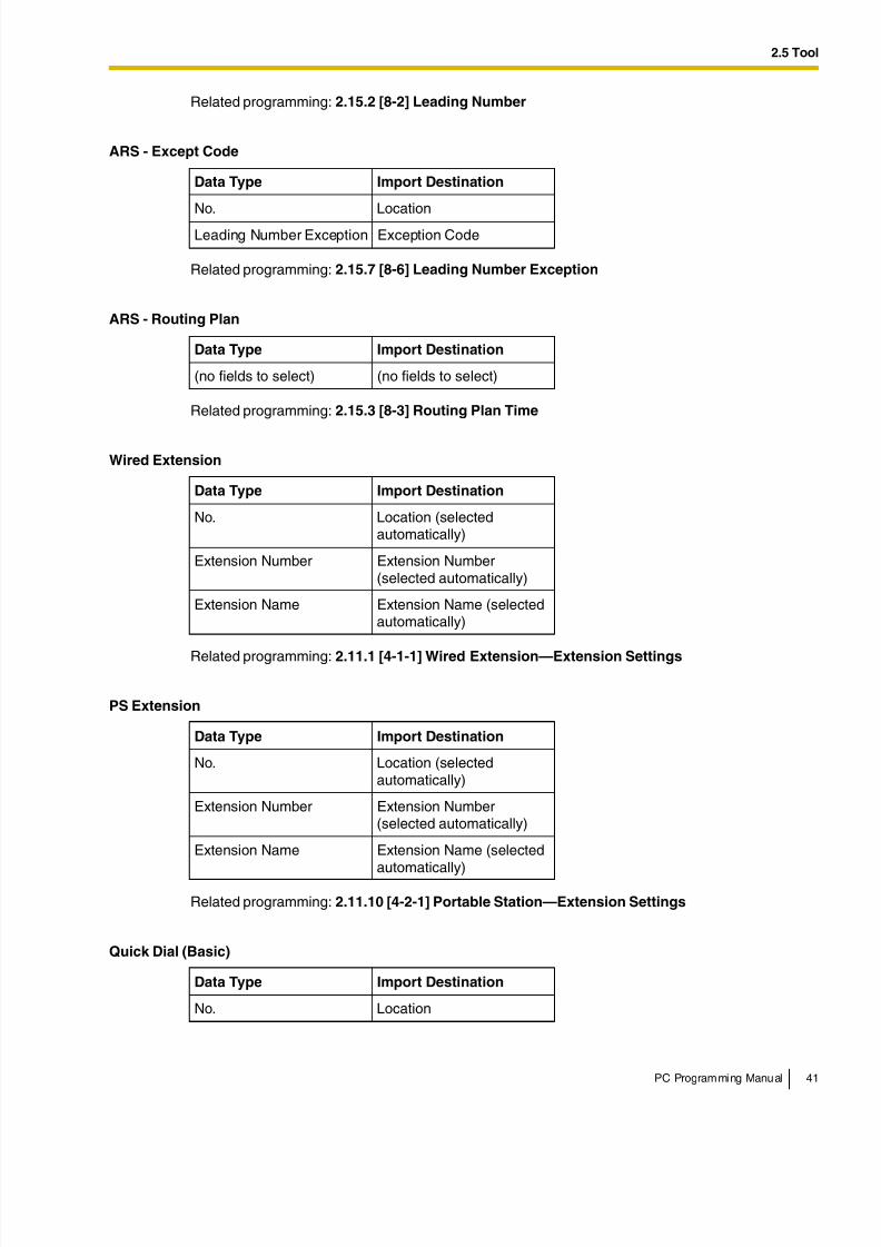
ARS - Leading Digit
Data Type Import Destination
No. Location
Leading Number Leading Digit
Additional Number of Digits Additional Dial Digits
Routing Plan Number Route Plan Number
8/11/2019 TDA ProgrammingManual
http://slidepdf.com/reader/full/tda-programmingmanual 41/720
2.5 Tool
PC Programming Manual 41
Related programming: 2.15.2 [8-2] Leading Number
Related programming: 2.15.7 [8-6] Leading Number Exception
Related programming: 2.15.3 [8-3] Routing Plan Time
Related programming: 2.11.1 [4-1-1] Wired Extension—Extension Settings
Related programming: 2.11.10 [4-2-1] Portable Station—Extension Settings
ARS - Except Code
Data Type Import Destination
No. Location
Leading Number Exception Exception Code
ARS - Routing Plan
Data Type Import Destination
(no fields to select) (no fields to select)
Wired Extension
Data Type Import Destination
No. Location (selectedautomatically)
Extension Number Extension Number(selected automatically)
Extension Name Extension Name (selectedautomatically)
PS Extension
Data Type Import Destination
No. Location (selectedautomatically)
Extension Number Extension Number(selected automatically)
Extension Name Extension Name (selected
automatically)
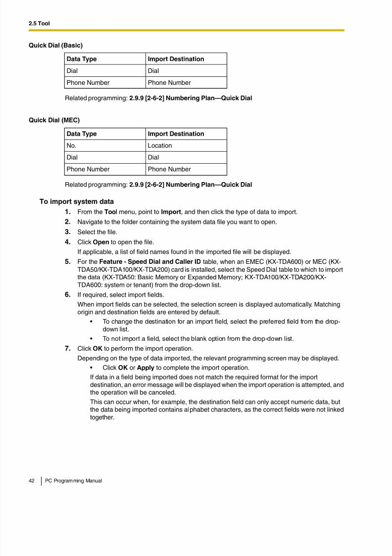
Quick Dial (Basic)
Data Type Import Destination
No. Location
8/11/2019 TDA ProgrammingManual
http://slidepdf.com/reader/full/tda-programmingmanual 42/720
2.5 Tool
42 PC Programming Manual
Related programming: 2.9.9 [2-6-2] Numbering Plan—Quick Dial
Related programming: 2.9.9 [2-6-2] Numbering Plan—Quick Dial
To import system data
1. From the Tool menu, point to Import, and then click the type of data to import.
2. Navigate to the folder containing the system data file you want to open.
3. Select the file.
4. Click Open to open the file.
If applicable, a list of field names found in the imported file will be displayed.
5. For the Feature - Speed Dial and Caller ID table, when an EMEC (KX-TDA600) or MEC (KX-TDA50/KX-TDA100/KX-TDA200) card is installed, select the Speed Dial table to which to importthe data (KX-TDA50: Basic Memory or Expanded Memory; KX-TDA100/KX-TDA200/KX-TDA600: system or tenant) from the drop-down list.
6. If required, select import fields.
When import fields can be selected, the selection screen is displayed automatically. Matchingorigin and destination fields are entered by default.
• To change the destination for an import field, select the preferred field from the drop-down list.
• To not import a field, select the blank option from the drop-down list.
7. Click OK to perform the import operation.
Depending on the type of data imported, the relevant programming screen may be displayed.
• Click OK or Apply to complete the import operation.
If data in a field being imported does not match the required format for the importdestination, an error message will be displayed when the import operation is attempted, andthe operation will be canceled.
This can occur when, for example, the destination field can only accept numeric data, butthe data being imported contains alphabet characters, as the correct fields were not linkedtogether.
Dial Dial
Phone Number Phone Number
Quick Dial (MEC)
Data Type Import Destination
No. Location
Dial Dial
Phone Number Phone Number
Quick Dial (Basic)
Data Type Import Destination
8/11/2019 TDA ProgrammingManual
http://slidepdf.com/reader/full/tda-programmingmanual 43/720
2.5 Tool
PC Programming Manual 43
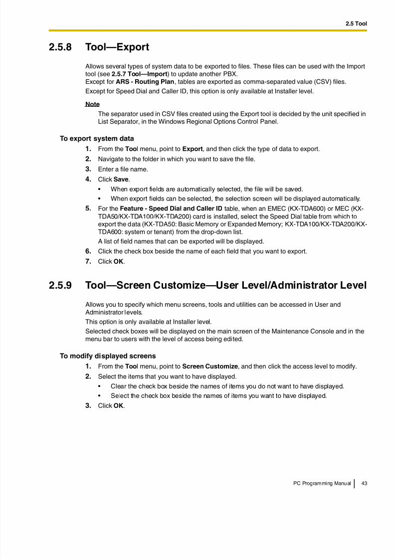
2.5.8 Tool—Export
Allows several types of system data to be exported to files. These files can be used with the Importtool (see 2.5.7 Tool—Import) to update another PBX.Except for ARS - Routing Plan, tables are exported as comma-separated value (CSV) files.
Except for Speed Dial and Caller ID, this option is only available at Installer level.
Note
The separator used in CSV files created using the Export tool is decided by the unit specified inList Separator, in the Windows Regional Options Control Panel.
To export system data
1. From the Tool menu, point to Export, and then click the type of data to export.
2. Navigate to the folder in which you want to save the file.
3. Enter a file name.
4. Click Save.
• When export fields are automatically selected, the file will be saved.
• When export fields can be selected, the selection screen will be displayed automatically.
5. For the Feature - Speed Dial and Caller ID table, when an EMEC (KX-TDA600) or MEC (KX-TDA50/KX-TDA100/KX-TDA200) card is installed, select the Speed Dial table from which toexport the data (KX-TDA50: Basic Memory or Expanded Memory; KX-TDA100/KX-TDA200/KX-TDA600: system or tenant) from the drop-down list.
A list of field names that can be exported will be displayed.
6. Click the check box beside the name of each field that you want to export.
7. Click OK.
2.5.9 Tool—Screen Customize—User Level/Administrator Level
Allows you to specify which menu screens, tools and utilities can be accessed in User andAdministrator levels.
This option is only available at Installer level.
Selected check boxes will be displayed on the main screen of the Maintenance Console and in themenu bar to users with the level of access being edited.
To modify displayed screens
1. From the Tool menu, point to Screen Customize, and then click the access level to modify.
2. Select the items that you want to have displayed.
• Clear the check box beside the names of items you do not want to have displayed.
• Select the check box beside the names of items you want to have displayed.
3. Click OK.
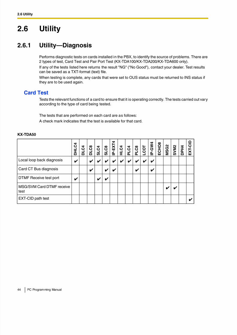
8/11/2019 TDA ProgrammingManual
http://slidepdf.com/reader/full/tda-programmingmanual 44/720
2.6 Utility
44 PC Programming Manual
2.6 Utility
2.6.1 Utility—Diagnosis
Performs diagnostic tests on cards installed in the PBX, to identify the source of problems. There are2 types of test, Card Test and Pair Port Test (KX-TDA100/KX-TDA200/KX-TDA600 only).
If any of the tests listed here returns the result "NG" ("No Good"), contact your dealer. Test resultscan be saved as a TXT-format (text) file.
When testing is complete, any cards that were set to OUS status must be returned to INS status ifthey are to be used again.
Card TestTests the relevant functions of a card to ensure that it is operating correctly. The tests carried out varyaccording to the type of card being tested.
The tests that are performed on each card are as follows:A check mark indicates that the test is available for that card.
KX-TDA50
D H L C 4
D L C 4
D L C 8
S L C 4
S L C 8
I P - E X T 4
H L C 4
P L C 4
P L C 8
L C O T
I P - G W 4
E C H O 8
M S G 2
S V M 2
D P H 4
E X T - C I D
Local loop back diagnosis
Card CT Bus diagnosis
DTMF Receive test port
MSG/SVM Card DTMF receivetest
EXT-CID path test
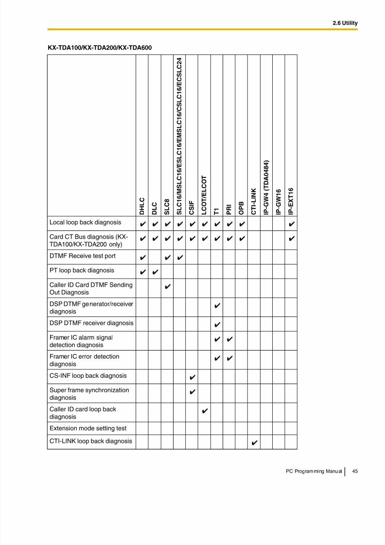
8/11/2019 TDA ProgrammingManual
http://slidepdf.com/reader/full/tda-programmingmanual 45/720
2.6 Utility
PC Programming Manual 45
KX-TDA100/KX-TDA200/KX-TDA600
D H L C
D L C
S L C 8
S L C 1 6 / M
S L C 1 6 / E S L C 1 6 / E M S L C 1 6 / C S L C 1 6 / E C S L C 2 4
C S I F
L C O T / E L
C O T
T 1
P R I
O P B
C T I - L I N K
I P - G W 4 (
T D A 0 4 8 4 )
I P - G W 1 6
I P - E X T 1 6
Local loop back diagnosis
Card CT Bus diagnosis (KX-TDA100/KX-TDA200 only)
DTMF Receive test port
PT loop back diagnosis
Caller ID Card DTMF SendingOut Diagnosis
DSP DTMF generator/receiverdiagnosis
DSP DTMF receiver diagnosis
Framer IC alarm signaldetection diagnosis
Framer IC error detectiondiagnosis
CS-INF loop back diagnosis
Super frame synchronizationdiagnosis
Caller ID card loop backdiagnosis
Extension mode setting test
CTI-LINK loop back diagnosis
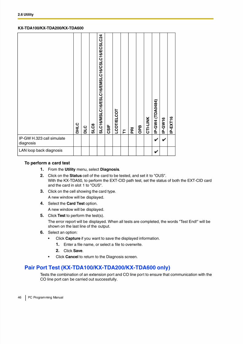
8/11/2019 TDA ProgrammingManual
http://slidepdf.com/reader/full/tda-programmingmanual 46/720
2.6 Utility
46 PC Programming Manual
To perform a card test
1. From the Utility menu, select Diagnosis.
2. Click on the Status cell of the card to be tested, and set it to "OUS".
With the KX-TDA50, to perform the EXT-CID path test, set the status of both the EXT-CID cardand the card in slot 1 to "OUS".
3. Click on the cell showing the card type.
A new window will be displayed.
4. Select the Card Test option.
A new window will be displayed.
5. Click Test to perform the test(s).
The error report will be displayed. When all tests are completed, the words "Test End!" will beshown on the last line of the output.
6. Select an option:
• Click Capture if you want to save the displayed information.
1. Enter a file name, or select a file to overwrite.
2. Click Save.
• Click Cancel to return to the Diagnosis screen.
Pair Port Test (KX-TDA100/KX-TDA200/KX-TDA600 only)Tests the combination of an extension port and CO line port to ensure that communication with theCO line port can be carried out successfully.
IP-GW H.323 call simulatediagnosis
LAN loop back diagnosis
KX-TDA100/KX-TDA200/KX-TDA600
D H L C
D L C
S L C 8
S L C 1 6 / M S L C 1 6 / E S L C 1 6 / E M S L C 1 6 / C S L C
1 6 / E C S L C 2 4
C S I F
L C O T / E
L C O T
T 1
P R I
O P B
C T I - L I N K
I P - G W 4
( T D A 0 4 8 4 )
I P - G W 1 6
I P - E X T 1
6
8/11/2019 TDA ProgrammingManual
http://slidepdf.com/reader/full/tda-programmingmanual 47/720
2.6 Utility
PC Programming Manual 47
The pair port test can be carried out using one LCOT or ELCOT card and one DHLC, SLC8, SLC16,MSLC16, ESLC16, EMSLC16, CSLC16, or ECSLC24 card.
Note
With the KX-TDA600, the pair of cards to be used for the pair port tests must be installed withinthe same shelf.
The tests that are performed are as follows:
To perform a pair port test
1. From the Utility menu, select Diagnosis.
2. Click on the Status cell of the extension card to be tested, and set it to "OUS".
3. Click on the cell showing the card type.
A new window will be displayed.
4. Select the Pair Port Test option.
A new window will be displayed. The card you selected in Step 3 will be shown in the Extension
Line Slot No. drop-down list.
5. From the CO Line Slot No. drop-down list, select the slot number of the CO line card you wantto test.
6. From the CO Line Port No. drop-down list, select the port number of the CO line you want to test.
7. Click Test.
The error report will be displayed.
8. Select an option:
• Click Capture if you want to save the displayed information.
1. Enter a file name, or select a file to overwrite.
2. Click Save.
• Click Cancel to return to the Diagnosis screen.
Network Loopback Test (KX-TDA100/KX-TDA200/KX-TDA600 only)Performs a remote loopback test on the PRI23 card.
Notes
• To perform this test, it is necessary to set Loopback Test started by Network in 2.8.14 [1-1] Slot—Port Property - PRI Port (KX-TDA100/KX-TDA200/KX-TDA600 only) to"Enable".
Line current OFF (Ext—>CO) Line current from extension to CO line turns off.
Line current ON (Ext—>CO) Line current from extension to CO line turns on.
Off hook detection (CO—>Ext) Off-hook generation/detection from CO line toextension
DTMF detection (CO—>Ext) DTMF generation/detection from CO line to extension
DP detection (CO—>Ext) DP generation/detection from CO line to extension
BELL detection (Ext—>CO) BELL generation/detection from extension to CO line
Speech path (Ext—>CO) Speech path from extension to CO line
Speech path (CO—>Ext) Speech path from CO line to extension
8/11/2019 TDA ProgrammingManual
http://slidepdf.com/reader/full/tda-programmingmanual 48/720
2.6 Utility
48 PC Programming Manual
• The version of the PRI23 card must be 2.000 or later.
To perform a network loopback test
1. From the Utility menu, select Diagnosis.
2. Click on the Status cell of the PRI23 card, and set it to "OUS".
3. Click on the cell showing the card type.
A new window will be displayed.
4. Select the Loopback Type option.
A new window will be displayed.
5. Select Point1 or Point2 depending on the type of loopback test you want to perform.
The available selections may vary depending on the hardware version of the card.
6. Click Apply.
Preparation for the test is complete. The test will start automatically.
7. After the test is complete, select Release and click Apply.
8. Click Close to return to the Diagnosis screen.
2.6.2 Utility—File Transfer PC to PBX (SD Card)
Copies PBX system files (program files and data files) from the connected PC to the SD memory cardinstalled in the PBX. Pre-existing files on the SD memory card are overwritten.
This option is only available at Installer level.
Two types of files can be copied using this tool:
• Program files: These contain the programs used to operate cards within the PBX and CSs,acting as on-board drivers.
• Data files: These contain the initial configuration data for individual cards and settings.
Not all files that are copied using this tool are automatically made active. To install new program filesor main system data to the PBX, use the System Reset—Reset by the Command utility (see 2.6.17Utility—System Reset—Reset by the Command) for PMPR/PSMPR/PLMPR and DSYS/DSSYS/ DLSYS files, and the SD Card File View and Load utility (see 2.6.4 Utility—SD Card File View andLoad) for all other files.
The PBX examines the header information of a file to determine 2 things: whether the file containssupported data, and which system component the file applies to.
Only files whose header information matches that of a system file supported by the PBX can betransferred. Attempting to transfer any other type of file results in an error message.
The names of all files that can be stored on the SD memory card are as follows:
Main Program
KX-TDA50
Name on SD Memory Card Corresponding Card
PSMPR MPR
PSMPR_S MPR*
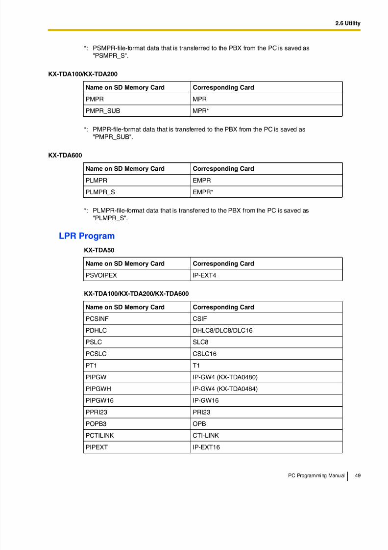
8/11/2019 TDA ProgrammingManual
http://slidepdf.com/reader/full/tda-programmingmanual 49/720
2.6 Utility
PC Programming Manual 49
LPR Program
*: PSMPR-file-format data that is transferred to the PBX from the PC is saved as"PSMPR_S".
KX-TDA100/KX-TDA200
Name on SD Memory Card Corresponding Card
PMPR MPR
PMPR_SUB MPR*
*: PMPR-file-format data that is transferred to the PBX from the PC is saved as"PMPR_SUB".
KX-TDA600
Name on SD Memory Card Corresponding Card
PLMPR EMPR
PLMPR_S EMPR*
*: PLMPR-file-format data that is transferred to the PBX from the PC is saved as"PLMPR_S".
KX-TDA50
Name on SD Memory Card Corresponding Card
PSVOIPEX IP-EXT4
KX-TDA100/KX-TDA200/KX-TDA600
Name on SD Memory Card Corresponding Card
PCSINF CSIF
PDHLC DHLC8/DLC8/DLC16
PSLC SLC8
PCSLC CSLC16
PT1 T1
PIPGW IP-GW4 (KX-TDA0480)
PIPGWH IP-GW4 (KX-TDA0484)
PIPGW16 IP-GW16
PPRI23 PRI23
POPB3 OPB
PCTILINK CTI-LINK
PIPEXT IP-EXT16
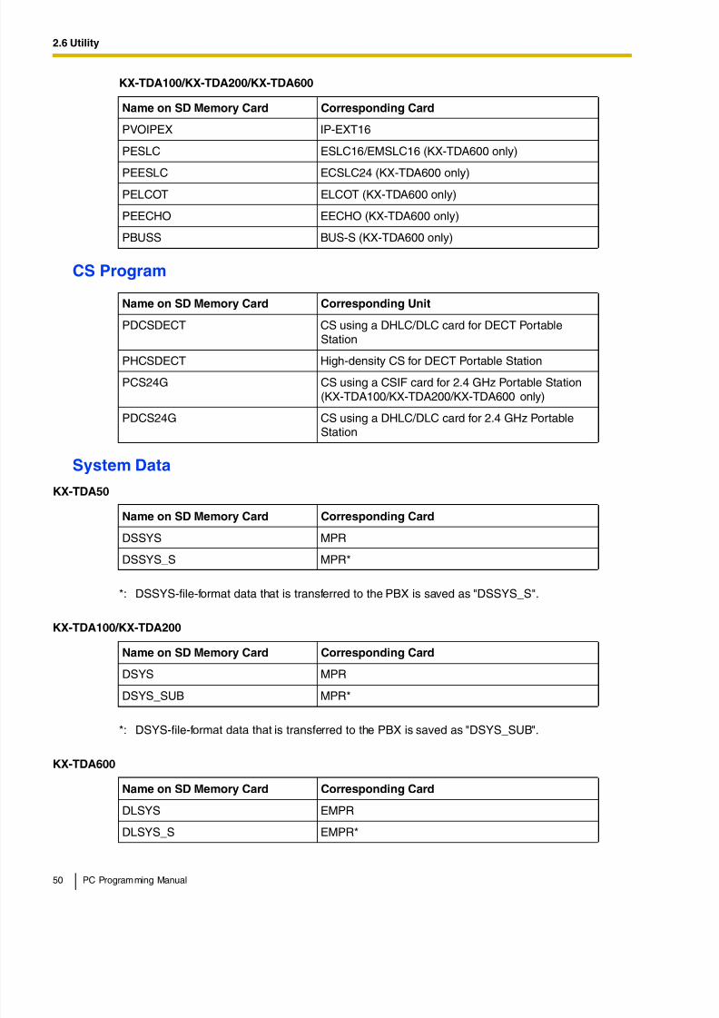
8/11/2019 TDA ProgrammingManual
http://slidepdf.com/reader/full/tda-programmingmanual 50/720
2.6 Utility
50 PC Programming Manual
CS Program
System Data
PVOIPEX IP-EXT16
PESLC ESLC16/EMSLC16 (KX-TDA600 only)
PEESLC ECSLC24 (KX-TDA600 only)PELCOT ELCOT (KX-TDA600 only)
PEECHO EECHO (KX-TDA600 only)
PBUSS BUS-S (KX-TDA600 only)
Name on SD Memory Card Corresponding Unit
PDCSDECT CS using a DHLC/DLC card for DECT PortableStation
PHCSDECT High-density CS for DECT Portable Station
PCS24G CS using a CSIF card for 2.4 GHz Portable Station(KX-TDA100/KX-TDA200/KX-TDA600 only)
PDCS24G CS using a DHLC/DLC card for 2.4 GHz PortableStation
KX-TDA50
Name on SD Memory Card Corresponding Card
DSSYS MPR
DSSYS_S MPR*
*: DSSYS-file-format data that is transferred to the PBX is saved as "DSSYS_S".
KX-TDA100/KX-TDA200
Name on SD Memory Card Corresponding Card
DSYS MPR
DSYS_SUB MPR*
*: DSYS-file-format data that is transferred to the PBX is saved as "DSYS_SUB".
KX-TDA600
Name on SD Memory Card Corresponding Card
DLSYS EMPR
DLSYS_S EMPR*
KX-TDA100/KX-TDA200/KX-TDA600
Name on SD Memory Card Corresponding Card
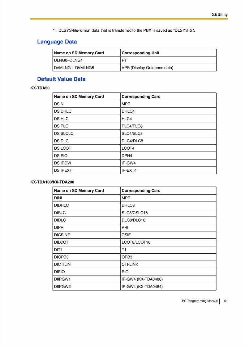
8/11/2019 TDA ProgrammingManual
http://slidepdf.com/reader/full/tda-programmingmanual 51/720
2.6 Utility
PC Programming Manual 51
Language Data
Default Value Data
*: DLSYS-file-format data that is transferred to the PBX is saved as "DLSYS_S".
Name on SD Memory Card Corresponding Unit
DLNG0–DLNG1 PT
DVMLNG1–DVMLNG5 VPS (Display Guidance data)
KX-TDA50
Name on SD Memory Card Corresponding Card
DSINI MPR
DSIDHLC DHLC4
DSIHLC HLC4
DSIPLC PLC4/PLC8
DSISLCLC SLC4/SLC8
DSIDLC DLC4/DLC8
DSILCOT LCOT4
DSIEIO DPH4
DSIIPGW IP-GW4
DSIIPEXT IP-EXT4
KX-TDA100/KX-TDA200
Name on SD Memory Card Corresponding Card
DINI MPR
DIDHLC DHLC8
DISLC SLC8/CSLC16
DIDLC DLC8/DLC16
DIPRI PRI
DICSINF CSIF
DILCOT LCOT8/LCOT16DIT1 T1
DIOPB3 OPB3
DICTILIN CTI-LINK
DIEIO EIO
DIIPGW1 IP-GW4 (KX-TDA0480)
DIIPGW2 IP-GW4 (KX-TDA0484)
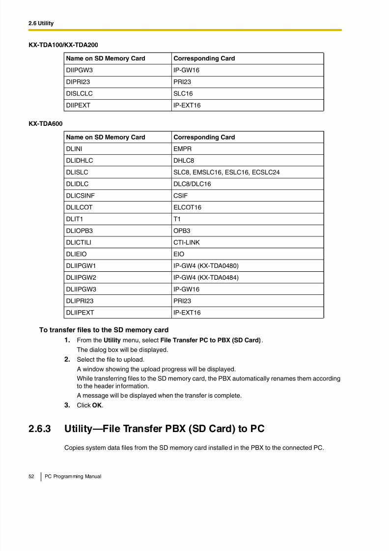
8/11/2019 TDA ProgrammingManual
http://slidepdf.com/reader/full/tda-programmingmanual 52/720
2.6 Utility
52 PC Programming Manual
To transfer files to the SD memory card
1. From the Utility menu, select File Transfer PC to PBX (SD Card).
The dialog box will be displayed.
2. Select the file to upload.
A window showing the upload progress will be displayed.
While transferring files to the SD memory card, the PBX automatically renames them according
to the header information.A message will be displayed when the transfer is complete.
3. Click OK.
2.6.3 Utility—File Transfer PBX (SD Card) to PC
Copies system data files from the SD memory card installed in the PBX to the connected PC.
DIIPGW3 IP-GW16
DIPRI23 PRI23
DISLCLC SLC16DIIPEXT IP-EXT16
KX-TDA600
Name on SD Memory Card Corresponding Card
DLINI EMPR
DLIDHLC DHLC8
DLISLC SLC8, EMSLC16, ESLC16, ECSLC24
DLIDLC DLC8/DLC16
DLICSINF CSIF
DLILCOT ELCOT16
DLIT1 T1
DLIOPB3 OPB3
DLICTILI CTI-LINK
DLIEIO EIO
DLIIPGW1 IP-GW4 (KX-TDA0480)
DLIIPGW2 IP-GW4 (KX-TDA0484)
DLIIPGW3 IP-GW16
DLIPRI23 PRI23
DLIIPEXT IP-EXT16
KX-TDA100/KX-TDA200
Name on SD Memory Card Corresponding Card
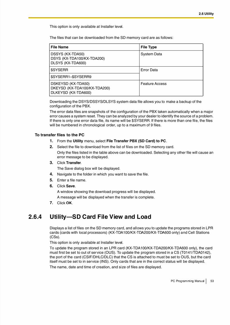
8/11/2019 TDA ProgrammingManual
http://slidepdf.com/reader/full/tda-programmingmanual 53/720
2.6 Utility
PC Programming Manual 53
This option is only available at Installer level.
The files that can be downloaded from the SD memory card are as follows:
Downloading the DSYS/DSSYS/DLSYS system data file allows you to make a backup of theconfiguration of the PBX.
The error data files are snapshots of the configuration of the PBX taken automatically when a majorerror causes a system reset. They can be analyzed by your dealer to identify the source of a problem.If there is only one error data file, its name will be $SYSERR. If there is more than one file, the fileswill be numbered in chronological order, up to a maximum of 9 files.
To transfer files to the PC
1. From the Utility menu, select File Transfer PBX (SD Card) to PC.
2. Select the file to download from the list of files on the SD memory card.
Only the files listed in the table above can be downloaded. Selecting any other file will cause anerror message to be displayed.
3. Click Transfer.
The Save dialog box will be displayed.
4. Navigate to the folder in which you want to save the file.
5. Enter a file name.
6. Click Save.
A window showing the download progress will be displayed.
A message will be displayed when the transfer is complete.
7. Click OK.
2.6.4 Utility—SD Card File View and Load
Displays a list of files on the SD memory card, and allows you to update the programs stored in LPRcards (cards with local processors) (KX-TDA100/KX-TDA200/KX-TDA600 only) and Cell Stations(CSs).
This option is only available at Installer level.
To update the program stored in an LPR card (KX-TDA100/KX-TDA200/KX-TDA600 only), the cardmust first be set to out of service (OUS). To update the program stored in a CS (T0141/TDA0142),the port of the card (CSIF/DHLC/DLC) that the CS is attached to must be set to OUS, but the carditself must be set to in service (INS). Only cards that are in the correct status will be displayed.
The name, date and time of creation, and size of files are displayed.
File Name File Type
DSSYS (KX-TDA50)DSYS (KX-TDA100/KX-TDA200)DLSYS (KX-TDA600)
System Data
$SYSERR Error Data
$SYSERR1–$SYSERR9
DSKEYSD (KX-TDA50)DKEYSD (KX-TDA100/KX-TDA200)DLKEYSD (KX-TDA600)
Feature Access
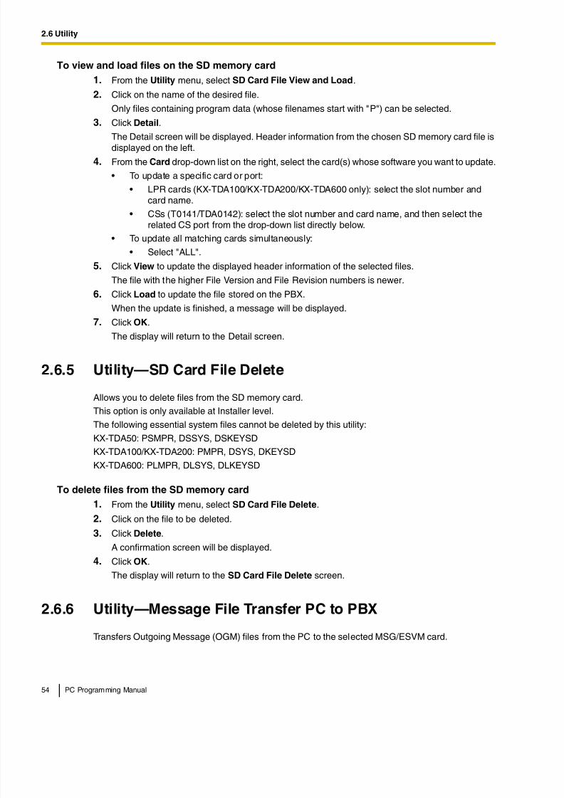
8/11/2019 TDA ProgrammingManual
http://slidepdf.com/reader/full/tda-programmingmanual 54/720
2.6 Utility
54 PC Programming Manual
To view and load files on the SD memory card
1. From the Utility menu, select SD Card File View and Load.
2. Click on the name of the desired file.
Only files containing program data (whose filenames start with "P") can be selected.
3. Click Detail.
The Detail screen will be displayed. Header information from the chosen SD memory card file isdisplayed on the left.
4. From the Card drop-down list on the right, select the card(s) whose software you want to update.
• To update a specific card or port:
• LPR cards (KX-TDA100/KX-TDA200/KX-TDA600 only): select the slot number andcard name.
• CSs (T0141/TDA0142): select the slot number and card name, and then select therelated CS port from the drop-down list directly below.
• To update all matching cards simultaneously:
• Select "ALL".
5. Click View to update the displayed header information of the selected files.
The file with the higher File Version and File Revision numbers is newer.6. Click Load to update the file stored on the PBX.
When the update is finished, a message will be displayed.
7. Click OK.
The display will return to the Detail screen.
2.6.5 Utility—SD Card File Delete
Allows you to delete files from the SD memory card.
This option is only available at Installer level.
The following essential system files cannot be deleted by this utility:
KX-TDA50: PSMPR, DSSYS, DSKEYSD
KX-TDA100/KX-TDA200: PMPR, DSYS, DKEYSD
KX-TDA600: PLMPR, DLSYS, DLKEYSD
To delete files from the SD memory card
1. From the Utility menu, select SD Card File Delete.
2. Click on the file to be deleted.
3. Click Delete.
A confirmation screen will be displayed.
4. Click OK.
The display will return to the SD Card File Delete screen.
2.6.6 Utility—Message File Transfer PC to PBX
Transfers Outgoing Message (OGM) files from the PC to the selected MSG/ESVM card.
8/11/2019 TDA ProgrammingManual
http://slidepdf.com/reader/full/tda-programmingmanual 55/720
2.6 Utility
PC Programming Manual 55
This option is only available at Installer level, and requires that at least 1 MSG/ESVM card is installed.For the KX-TDA100/KX-TDA200/KX-TDA600, the OPB card that it is mounted on must be set to OUSstatus. For the KX-TDA50, the MSG card must be set to OUS status.
Files are stored on the MSG/ESVM card in the location specified by the file's header information.Uploaded files are automatically renamed as necessary. If this location already contains an OGM, itwill be overwritten by the newly uploaded message.
To transfer OGMs to an MSG/ESVM card
1. From the Utility menu, select Message File Transfer PC to PBX.
2. Select the target MSG/ESVM card, or "ALL", from the drop-down list, and click OK.
The Open dialog box will be displayed.
3. Select the message files to upload.
It is possible to select multiple files.
4. Click OK.
The files will be uploaded. Files that do not contain message data will be ignored.
When complete, the display will return to the main screen.
2.6.7 Utility—Message File Transfer PBX to PC
Transfers Outgoing Message (OGM) files from the MSG/ESVM card to the PC.
This option is only available at Installer level, and requires that at least 1 MSG/ESVM card is installed.For the KX-TDA100/KX-TDA200/KX-TDA600, the OPB card that it is mounted on must be set to OUSstatus. For the KX-TDA50, the MSG card must be set to OUS status.
To transfer OGMs to the PC
1. From the Utility menu, select Message File Transfer PBX to PC.
2. From the upper drop-down list, select the target MSG/ESVM card.
3. From the lower drop-down list, select the messages to transfer.
• To transfer a certain message, select the number of that message.
• To transfer all messages at once, select "ALL".
The Save dialog box will be displayed.
4. Enter a file name.
5. Click Save.
6. Click OK.
When you choose to transfer all messages, each message is saved as an individual file, with anumber appended to the file name corresponding to that message's location on the MSG/ESVMcard.
When complete, the display will return to the main screen.
2.6.8 Utility—Error Log
Collects and displays system error information.
Whenever there is a system failure, the PBX stores the error code generated. The connected PCcollects all of these codes, along with other information, and displays an explanatory error message.
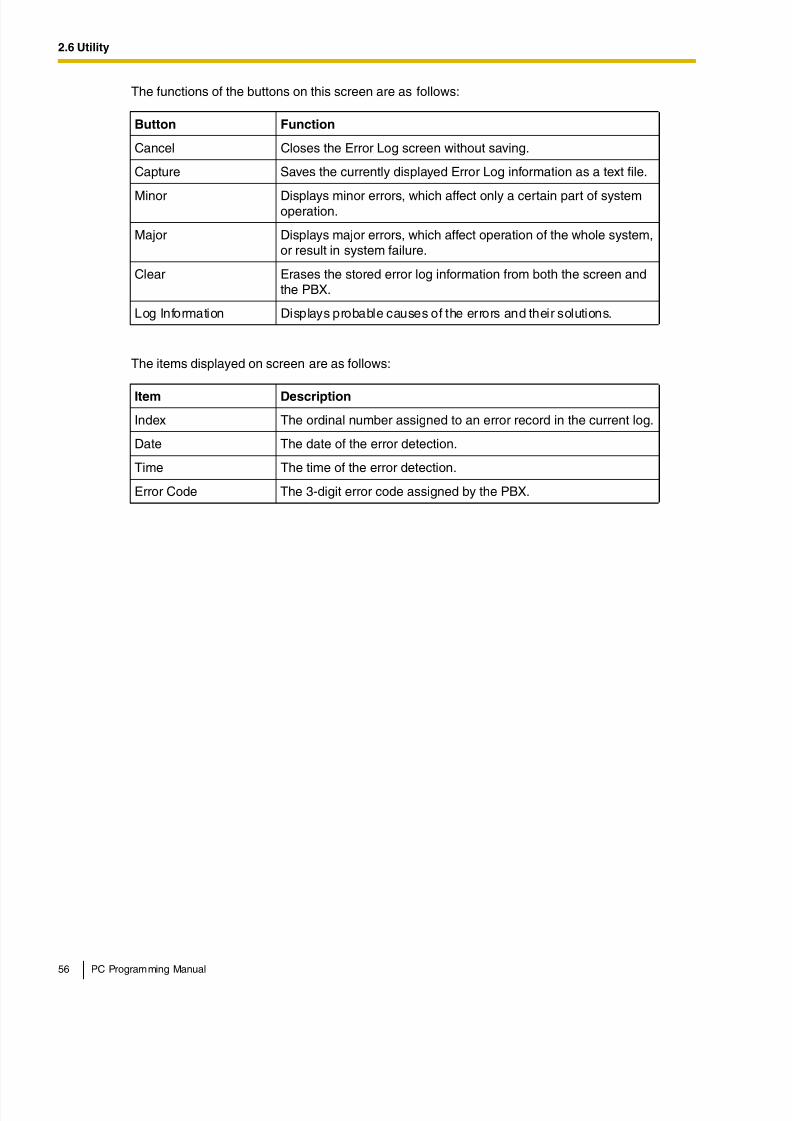
8/11/2019 TDA ProgrammingManual
http://slidepdf.com/reader/full/tda-programmingmanual 56/720
2.6 Utility
56 PC Programming Manual
The functions of the buttons on this screen are as follows:
The items displayed on screen are as follows:
Button Function
Cancel Closes the Error Log screen without saving.
Capture Saves the currently displayed Error Log information as a text file.
Minor Displays minor errors, which affect only a certain part of systemoperation.
Major Displays major errors, which affect operation of the whole system,or result in system failure.
Clear Erases the stored error log information from both the screen andthe PBX.
Log Information Displays probable causes of the errors and their solutions.
Item Description
Index The ordinal number assigned to an error record in the current log.
Date The date of the error detection.
Time The time of the error detection.
Error Code The 3-digit error code assigned by the PBX.
8/11/2019 TDA ProgrammingManual
http://slidepdf.com/reader/full/tda-programmingmanual 57/720
2.6 Utility
PC Programming Manual 57
To view the error log
• From the Utility menu, select Error Log.
2.6.9 Utility—T1 Signaling Bit Monitor (KX-TDA100/KX-TDA200/ KX-TDA600 only)
Displays reference signaling bit information for all channels of the T1 card, by monitoring sent andreceived A, B, C and D bits. This utility is intended for use by dealers.
This option is only available at Installer level, and requires that the target T1 card be set to INS status.While monitoring is being performed, any displayed bits whose value changes from 0 to 1 or viceversa will be highlighted in red until the next screen refresh is performed.
To view signaling bit information
1. From the Utility menu, select T1 Signaling Bit Monitor.
2. From the Slot No drop-down list, select the target slot.
3. From the Interval Timer drop-down list, select the number of seconds between each automaticscreen refresh.
Sub Code The 5-digit sub code of the relevant hardware. (XYYZZ)
• X: Shelf numberKX-TDA50/KX-TDA100/KX-TDA200: 1KX-TDA600:
• 1: Basic Shelf• 2: Expansion Shelf 1
• 3: Expansion Shelf 2
• 4: Expansion Shelf 3
• YY: Slot number
KX-TDA50: 00 to 11 (00: MPR slot; 01: Fixed slot, 02 to04: Free slot type A, 05 to 07: Free slot type B, 08 to 11:Option slot)
KX-TDA100: 00 to 06 (00: MPR slot; 01 to 06: Free slot)
KX-TDA200: 00 to 11 (00: MPR slot; 01 to 11: Free slot)KX-TDA600:
• Basic Shelf: 00 to 10(00: EMPR Card Slot; 01 to 10: Free Slots)
• Expansion Shelf: 01 to 12
(01 to 11: Free Slots; 12: BUS-S Card Slot)
• ZZ: Physical port number (01 to 16)
For OPB3 card, sub slot number (1 to 3) + port number (1to 4) will be displayed as follows:
• Sub slot 1 of OPB3: 11 to 14
• Sub slot 2 of OPB3: 21 to 24
• Sub slot 3 of OPB3: 31 to 34
Error Message A description of the error.
Item Description
8/11/2019 TDA ProgrammingManual
http://slidepdf.com/reader/full/tda-programmingmanual 58/720
2.6 Utility
58 PC Programming Manual
4. Click Start.
Monitoring will be performed and the screen will refresh according to the interval specified.
5. Click Stop to end monitoring.
To refresh the screen at any time while monitoring is stopped, click Refresh.
2.6.10 Utility—T1 Line Trace (KX-TDA100/KX-TDA200/KX-TDA600only)
Traces the sent and received signaling bits and dial numbers on the specified channel of the T1 line.This utility is intended for use by dealers.
This option is only available at Installer level, and requires that the target T1 card be set to INS status.
To view T1 trace data
1. From the Utility menu, select T1 Line Trace.
2. From the Slot No drop-down list, select the target slot.
3. From the CH No drop-down list, select the target channel.4. Click Start.
Trace information will be displayed. The information is automatically updated whenever the databeing monitored changes.
5. Click Stop to end the trace.
6. Select an option:
• Click Capture to save the displayed trace information.
Information is saved as a text-format file.
• Click Clear to erase the information.
2.6.11 Utility—ISDN/QSIG Protocol Trace
This utility collects protocol trace data from PRI or IP-GW cards, and displays it on the PC.
This option is only available at Installer level, and requires that the target PRI or IP-GW card be setto INS status.
Protocol trace data is continually accumulated on ISDN and IP-GW cards, and 3 types of data can bedownloaded:
• Real Time Trace (not available when connecting via LAN): Pseudo-real-time data is collectedthrough data polling at one-second intervals. The displayed information is updated beginningwhen the Start button is clicked.
• Accumulation Trace: Previously accumulated data is retrieved and displayed.
• Error Accumulation Trace: Previously accumulated error data is retrieved and displayed. Thistrace shows the data snapshot that is taken just before a card resets.
To view trace data
1. From the Utility menu, select ISDN/QSIG Protocol Trace.
2. From the Slot No drop-down list, select the target slot.
3. From the Trace Data Type drop-down list, select the type of data to view.
4. Click Start.

8/11/2019 TDA ProgrammingManual
http://slidepdf.com/reader/full/tda-programmingmanual 59/720
2.6 Utility
PC Programming Manual 59
Trace information will be displayed.
5. Select an option:
• Click Capture to save the displayed trace information.
• Click Clear to clear the screen display.
6. Click Cancel to return to the main screen.
2.6.12 Utility—Digital Trunk Error Report (KX-TDA100/KX-TDA200/KX-TDA600 only)
Displays accumulated information on various types of errors occurring on digital CO lines.
This option is only available at Installer level.
The value displayed for each error item is the number of times that each error occurred during thetime period selected. Average values for these items vary depending upon many factors, such as theequipment being used, and the distance from the telephone company.
The displayed items are as follows:
To view digital CO line information1. From the Utility menu, select Digital Trunk Error Report.
2. From the Slot No drop-down list, select the target slot.
• To generate a report on a specific card, select the slot number and card name.
• To generate a report on all matching cards simultaneously, select "ALL".
3. From the Display form drop-down list, select the time period to view.
4. Click Execute.
The error report will be displayed.
Item Description
Time Time of error
Slot Relevant slot and card type
Counter of Digital TrunkError Logs logged inMinor Error Log
Out of SYNC (#300) Digital CO line out of sync (Loss ofSignal)
RAI (#301) Digital CO line RAI signal reception
AIS (#302) Digital CO line Alarm Indication Signalreception
Frame Failure (#300) Digital CO line frame failure (Loss ofFrame)
Counter of minorcommunication error
CRC Cyclic Redundancy Check error
SF Severely errored frame (or SevereFraming Error)
FE Frame synchronization bit-error
LV Line Code Violation
SL Controlled slip
8/11/2019 TDA ProgrammingManual
http://slidepdf.com/reader/full/tda-programmingmanual 60/720
2.6 Utility
60 PC Programming Manual
2.6.13 Utility—IP Extension Statistical Information
Displays accumulated statistical information on both IP extensions and IP-EXT cards.
The displayed items are as follows:
To view IP extension information
1. From the Utility menu, select IP Extension Statistical Information.
2. From the Card Selection drop-down list, select the slot number.
3. Click Execute.
The statistical information will be displayed.
4. Select an option:
• Click Capture if you want to save the displayed information.
1. Enter a file name, or select a file to overwrite.
2. Click Save.
• Click Clear to erase the information and reset the Collection Started Time.
5. Click Cancel to return to the main screen.
2.6.14 Utility—CS Information
Displays information stored by the PBX regarding each Cell Station (CS).
This option is only available at Installer level, and requires that the target CSIF, DHLC or DLC card beset to INS status.
The displayed items are as follows:
Item Description
Collection Started Time Date and time the port was last reset.
Port No. Number of the port.
RTP Receive Packet Counter Total number of packets received.
RTP Receive Lost Packet Counter Total number of packets lost.
RTP Receive Abandoned Packet Counter Total number of packets abandoned.
RTP Arrive Packet Interval (MAX.) [ms] Maximum time taken for a packet toarrive.
RTP Arrive Packet Interval (MIN.) [ms] Minimum time taken for a packet toarrive.
Item Description
Shelf-Slot Number of the slot (for KX-TDA600, shelf and slot)
Port Number of the port
CS Name Name of the attached CS

8/11/2019 TDA ProgrammingManual
http://slidepdf.com/reader/full/tda-programmingmanual 61/720
2.6 Utility
PC Programming Manual 61
To view CS information
1. From the Utility menu, select CS Information.
2. From the Target CSI/F Slot No drop-down list, select the target slot.
• To display information on a single card, select the slot number and name of that card.
• To display information on all matching cards, select "ALL".
3. From the Interval Timer drop-down list, select the number of seconds between each automaticscreen refresh.
4. Click Start to begin monitoring.Monitoring will be performed and the screen will refresh according to the interval specified.
To refresh the screen manually at any time, click Refresh.
5. Click Stop to end monitoring.
6. Select an option:
• Click Capture if you want to save the displayed information.
1. Enter a file name, or select a file to overwrite.
2. Click Save.
• Click Cancel to return to the main screen.
2.6.15 Utility—PS Information
Displays Portable Station (PS) registration information, including the associated Cell Station (CS).
This option is only available at Installer level.
The displayed items are as follows:
Status Service status of the attached CS: INS, OUS, or FAULT.
If the status is FAULT, subsequent data items for that port will be leftblank.
Version Version number of the program file stored in the CS
Revision Revision number of the program file stored in the CS
CSID 12-digit ID number of the CS
Path Number of the wireless extension currently using each path. In thecase of a group, several extensions may be using the same floatingextension number.
When an extension number is not registered, the display shows"OFF". 2.4 GHz PSs can use up to 3 paths (KX-TDA100/KX-TDA200/KX-TDA600) or 2 paths (KX-TDA50). DECT PSs can useup to 4 paths (KX-TDA100/KX-TDA200/KX-TDA600) or 2 paths(KX-TDA50). When using high-density CSs, DECT PSs can use upto 8 paths.
Group Call Number of PSs registered to the attached CS that are members ofa PS Ring Group.
Item Description
8/11/2019 TDA ProgrammingManual
http://slidepdf.com/reader/full/tda-programmingmanual 62/720
2.6 Utility
62 PC Programming Manual
To view PS information
1. From the Utility menu, select PS Information.
2. Click Refresh.
2.6.16 Utility—Timed Update (KX-TDA100/KX-TDA200/KX-TDA600 only)
Updates programs in the LPR cards (optional service cards with local processors) by comparing themwith files found on the SD memory card on a preset schedule, and downloading newer files to thecards.
This option is only available at Installer level.
It is recommended to set the timed update to take place during the least active time period, forexample late at night.
Cards are automatically set to OUS status during an update, and returned to INS status when theupdate is complete.
This utility does not apply to CS programs. These must be updated manually using the SD Card FileView and Load utility (see 2.6.4 Utility—SD Card File View and Load).
When this utility has been set, all commands that would affect the status of cards are prevented fromoperating.
The list of these commands is as follows:
• Card status change (INS/OUS)
• Diagnosis commands
• Card installation
• Card deletion
• Remote reset
• LPR program download requests
• Signaling Bit Monitor requests (T1)• Line trace start requests (T1)
• ISDN/QSIG Protocol Data Trace start requests
• Time setting
• CS program download requests
• File deletion
When a function other than those listed above, that cannot be performed while Timed Update hasbeen set, is selected, an error message will be displayed.
Item Description
PS No. PS location number.
Only registered PSs will be displayed.
Extension Number Extension number of the PS.
Location—Slot Slot number of the CS that the PS is registered with.
Location—Port Port number of the CS that the PS is registered with.
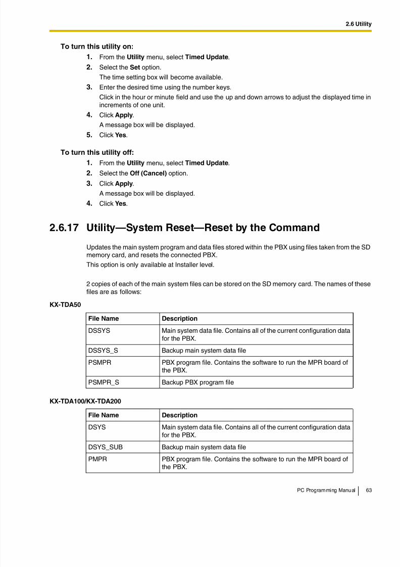
8/11/2019 TDA ProgrammingManual
http://slidepdf.com/reader/full/tda-programmingmanual 63/720
2.6 Utility
PC Programming Manual 63
To turn this utility on:
1. From the Utility menu, select Timed Update.
2. Select the Set option.
The time setting box will become available.
3. Enter the desired time using the number keys.
Click in the hour or minute field and use the up and down arrows to adjust the displayed time inincrements of one unit.
4. Click Apply.
A message box will be displayed.
5. Click Yes.
To turn this utility off:
1. From the Utility menu, select Timed Update.
2. Select the Off (Cancel) option.
3. Click Apply.
A message box will be displayed.
4. Click Yes.
2.6.17 Utility—System Reset—Reset by the Command
Updates the main system program and data files stored within the PBX using files taken from the SDmemory card, and resets the connected PBX.
This option is only available at Installer level.
2 copies of each of the main system files can be stored on the SD memory card. The names of thesefiles are as follows:
KX-TDA50
File Name Description
DSSYS Main system data file. Contains all of the current configuration datafor the PBX.
DSSYS_S Backup main system data file
PSMPR PBX program file. Contains the software to run the MPR board ofthe PBX.
PSMPR_S Backup PBX program file
KX-TDA100/KX-TDA200
File Name Description
DSYS Main system data file. Contains all of the current configuration datafor the PBX.
DSYS_SUB Backup main system data file
PMPR PBX program file. Contains the software to run the MPR board ofthe PBX.
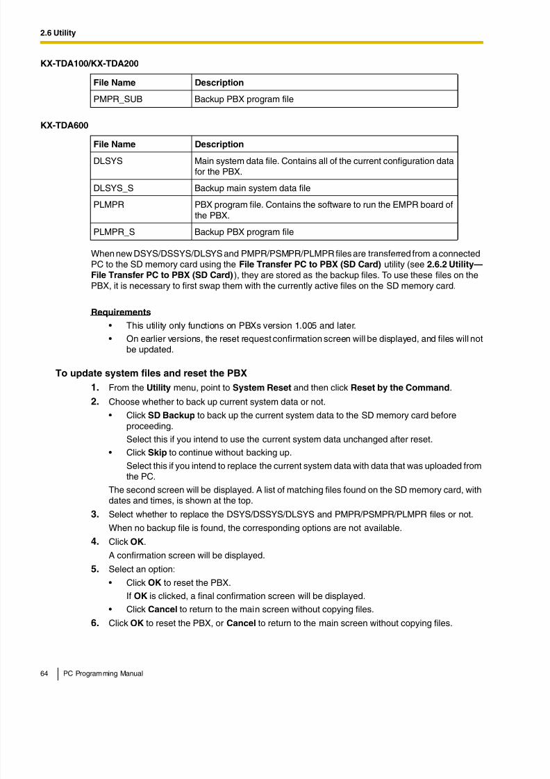
8/11/2019 TDA ProgrammingManual
http://slidepdf.com/reader/full/tda-programmingmanual 64/720
8/11/2019 TDA ProgrammingManual
http://slidepdf.com/reader/full/tda-programmingmanual 65/720

8/11/2019 TDA ProgrammingManual
http://slidepdf.com/reader/full/tda-programmingmanual 66/720
2.7 Help
66 PC Programming Manual
2.7 Help
2.7.1 Frequently Asked Questions (FAQ)
This section provides answers to some common questions about using the Maintenance Consolesoftware to program the PBX. The information is divided into the following topics:
Connection
Title Description
Connection Connecting to the PBX using Maintenance Console.
Maintenance Console Software Using the Maintenance Console software.
Card Status Changing the status (INS/OUS) of cards.
Portable Stations Setting up portable stations, including registration andderegistration.
Numbering Changing the numbering plan for the PBX, or numbers of individual
extensions or features.Saving Modified Data Safely saving PBX data edited with Maintenance Console.
Setting Features Setting up individual features.
Q The Maintenance Console cannot connect to the PBX via RS-232C cable.
A • Is the cable firmly connected to both the PC and the PBX?
• Is the serial port that the PC uses correctly specified?
• Is the baud rate correct?The default setting, and a safe rate, is 19 200 bps.
• Is the password correct?• Is the Maintenance Console not connected to the PBX by another connection method?
Q The Maintenance Console cannot connect to the PBX via USB.
A • Is the USB cable firmly connected to both the PC and the PBX?
• Is the USB driver on the PC running?To confirm, open the Windows Device Manager, and look for "Panasonic KX-TDA USBMain Unit driver" in the USB Controllers section. If it is not present, re-install the USBdriver.
• Is the password correct?
• Is the Maintenance Console not connected to the PBX by another connection method?
Q The Maintenance Console cannot connect to the PBX via LAN.
A • Is the PC connected to the LAN?
• Have the IP address and port number of the PBX been set correctly? For more details,see 2.8.28 [1-1] Slot—Card Property - CTILINK (KX-TDA100/KX-TDA200/KX-TDA600 only).
• Is the password correct?
• Is the Maintenance Console not connected to the PBX by another connection method?
8/11/2019 TDA ProgrammingManual
http://slidepdf.com/reader/full/tda-programmingmanual 67/720
2.7 Help
PC Programming Manual 67
Maintenance Console Software
Card Status
Q The Maintenance Console cannot connect to the PBX via modem.
A • Is the dial number of the modem correct? For more details, see 2.18.1 [11-1] Main.
• Has a modem been installed to the PBX?
• Are the modem settings of the PBX and Maintenance Console correct? For more details,see 2.18.1 [11-1] Main.
• Is the password correct?
• Is the Maintenance Console not connected to the PBX by another connection method?
Q Can I perform initial setup of the PBX without being connected to the PBX?
A • Yes. This is possible in Batch mode.Create a new system data file using 2.2.1 Start Menu—New, edit settings as required,and then upload this file to the PBX later (see 2.6.2 Utility—File Transfer PC to PBX(SD Card)).
Q How do I confirm the software version of the PBX or installed cards?
A • From 2.8.1 [1-1] Slot, click Summary. Summary information, including softwareversions, is displayed for all cards installed in the PBX.
Q Not all of the characters of a setting can be displayed because the column istoo narrow.
A • Move the mouse to the line between the names of 2 setting items, at the top of the table.The pointer will change to a double arrow. Click and drag the line to the right until allcharacters are displayed.
Q The status of a new card will not change to "INS".
A • With the new card installed, does the total number of extensions or CO lines exceed themaximum supported by the PBX?
• Is the type of card installed in the slot different from the card type set as "Pre-install" forthat slot? Confirm that the correct card is installed in the slot.
• Is the card firmly and fully installed in the slot? Confirm that the card is installed correctlyin the slot.
• Confirm that the card is not damaged.
Q I want to set the status of only 1 port of the IP-GW4 card to "OUS".
A • This cannot be done, since the IP-GW4 card requires both channels of a port to be setto "OUS"/"INS" together.
Q I cannot change an LCO port to INS status.
8/11/2019 TDA ProgrammingManual
http://slidepdf.com/reader/full/tda-programmingmanual 68/720
2.7 Help
68 PC Programming Manual
Portable Stations
A • Is the card installed in the appropriate slot?
• Is the card installed in the correct slot, but not functioning correctly?Check the condition of the card.
• Is the card itself in INS status?Set it to INS status.
• Is a CO line line connected to the appropriate port?
• Is the port in FAULT status, even though a CO line is connected?Run diagnosis on the relevant slot.
Q How do I prevent newly installed cards automatically being changed to "INS"?
A • Change New Card Installation—Card Status for any Card in 2.8.32 [1-3] Option from"In Service (INS)" to "Out of Service (OUS)".
Q I cannot register Portable Stations using the method described in PortableStation [1-2].
A • Is the status of the CSIF, DHLC or DLC card set to "INS"?
• Is a CS connected to the CSIF, DHLC or DLC card? If not, connect one.
• Do the PINs (Personal Identification Numbers) of the PBX and the Portable Stationmatch? Confirm that they are the same.
• Is the Portable Station within transmission range of the CS?
• Has the Portable Station previously been registered at another location?It is not possible to register a Portable Station at 2 locations, so use the Forced De-
registration option to delete the previous registration.
Q I cannot delete the extension number of a Portable Station.
A • First, de-register the Portable Station itself, and then delete the extension number.
Q I cannot de-register a Portable Station.
A • Is the Portable Station turned on? If not, turn it on.
• Is the Portable Station within transmission range of the CS? If not, move it closer to theCS and try the de-registration operation again.
Q The Portable Station I want to de-register is broken, and will not turn on, or isnot available, or the registration information was deleted first from the PortableStation, so it cannot be de-registered.
A • The Portable Station can be forcibly de-registered by the following the procedure shownin Forced De-registration of 2.8.31 [1-2] Portable Station.
Q I changed the extension number of a Portable Station, but the display of thePortable Station still shows the old extension number.
A • Turn the Portable Station off and back on again, to force it to re-register its location.
Q I changed the FCO of a Portable Station, but the display of the Portable Stationstill shows the old FCO.
A • Turn the Portable Station off and back on again, to force it to re-register its location.
8/11/2019 TDA ProgrammingManual
http://slidepdf.com/reader/full/tda-programmingmanual 69/720
2.7 Help
PC Programming Manual 69
Numbering
Q If I delete the extension number of a Portable Station, and then turn thePortable Station off and back on again, it does not function correctly.
A • Do not delete the extension number of the Portable Station, as this information isnecessary for it to operate.
Q How do I change the extension number of a wired extension?
A • Change the extension number of the target port to the new number, and click Apply.Next, set the port to OUS status, and then back to INS status.
Q I changed the extension number of a wired extension while the extension was
engaged in a call, but the display still shows the previous extension number.
A • The extension number will not change while the extension is in use. When theconversation is finished, set the port to OUS status, and then back to INS status.
Q How do I change the extension numbering plan from 3-digit numbers to 4-digit
numbers?A • Perform the following steps:
1. Open the 2.9.8 [2-6-1] Numbering Plan—Main screen.
2. Enter a 2-digit number in Leading Number, or change No. of Additional Digits from "x" to "xx".For more details, see What is the procedure to modify the Numbering Plan?.
Q How do I set a 3-digit numbering plan?
A • There are 2 methods of creating a 3-digit numbering plan, using 2.9.8 [2-6-1]
Numbering Plan—Main:
1. Set the leading number to be 2 digits, with one additional digit. This method allows
a maximum of 10 extensions.Example: Leading Number = 10; No. of Additional Digits = x
In this example, extension numbers 100 to 109 can be used.
2. Set the leading number to be one digit, with 2 additional digits. This method allowsa maximum of 100 extensions.
Example: Leading Number = 1; No. of Additional Digits = xx
In this example, extension numbers 100 to 199 can be used.
For more details, see What is the procedure to modify the Numbering Plan?.
Q What is the procedure to modify the Numbering Plan?
8/11/2019 TDA ProgrammingManual
http://slidepdf.com/reader/full/tda-programmingmanual 70/720
2.7 Help
70 PC Programming Manual
A • Perform the following steps:
1. Confirm that the Numbering Plan you will change is not currently being used by anyextensions (see 2.5.6 Tool—Extension List View).
If it is being used by extensions, temporarily change the extension numbers of thoseextensions to that of another numbering plan, or delete the extension number (see2.11.1 [4-1-1] Wired Extension—Extension Settings and 2.11.10 [4-2-1]
Portable Station—Extension Settings).2. Clear the Leading Number cell.
3. Click Apply.
4. Modify the No. of Additional Digits cell as required.
5. Click Apply.
6. Enter the desired value in the Leading Number cell.
7. Click Apply.
8. Set all extension ports to OUS status.
9. On the relevant screens, set the extension numbers of extensions to the desiredvalues.
10. Set all extension ports back to INS status.
Q When modifying the Numbering Plan, I cannot change the Leading Number.
A • It is not possible to use the same Leading Number for 2 extension blocks, or to use anumber that could possibly overlap with another Leading Number.So, for example, if "2" is already set as a Leading Number it is not possible to set "21" asanother Leading Number because of the possible overlap of extension numbers.The number you are trying to store cannot be used if it is already being used by:
• A feature number
• Another extension block
• A Dial setting (see 2.16.1 [9-1] TIE Table)
• Quick Dialing (see 2.9.9 [2-6-2] Numbering Plan—Quick Dial)In any of these cases, choose another number.
Q When modifying the Numbering Plan, how do I set a 1-digit extension number?
A • Perform the following steps:
1. Clear the Leading Number cell.
2. Click Apply.
3. Set No. of Additional Digits to "None".
4. Click Apply.
5. Enter the desired value in the Leading Number cell.
6. Click Apply.7. Set all extension ports to OUS status.
8. On the relevant screens, set the extension numbers of extensions to the desiredvalues.
9. Set all extension ports back to INS status.
Q How do I change a feature number?
8/11/2019 TDA ProgrammingManual
http://slidepdf.com/reader/full/tda-programmingmanual 71/720
2.7 Help
PC Programming Manual 71
Saving Modified Data
A • Perform the following steps:
1. Open the 2.9.8 [2-6-1] Numbering Plan—Main screen.
2. Change the value in the Dial cell of the desired feature.
3. Click Apply.
Q I cannot change a feature number.A • It is not possible to use the same number for 2 items.The number you are trying to store cannot be used if it is already being used by:
• A feature number
• An extension
• A Dial setting (see 2.16.1 [9-1] TIE Table)
• Quick Dialing (see 2.9.9 [2-6-2] Numbering Plan—Quick Dial)
In any of these cases, choose another number.
Q How do I change the code used to access another PBX?
A • Perform the following steps:
1. Open the 2.9.8 [2-6-1] Numbering Plan—Main screen.2. Select the Other PBX Extension tab.
3. Change the value in the Dial cell of the desired feature.
4. Click Apply.
Q I cannot change an Other PBX Extension code.
A • It is not possible to use the same number for 2 items.The number you are trying to store cannot be used if it is already being used by:
• A feature number
• An extension
• A Dial setting (see 2.16.1 [9-1] TIE Table)• Quick Dialing (see 2.9.9 [2-6-2] Numbering Plan—Quick Dial)
In any of these cases, choose another number.
Q I cannot change a feature number on the B/NA DND Call Feature screen.
A • The number you are trying to store is already being used by another call feature.Please choose a different number.
Q How do I prevent extension numbers being automatically assigned to a newlyinstalled card?
A • Change New Card Installation—Automatic Extension Number Set for Extension
Card in the 2.8.32 [1-3] Option screen from "Automatic" to "Manual".
Q Modified settings have not been updated in the PBX.
A • Click Apply or OK in the sub-menu screen.
Q Modified settings are not saved even when I press the Apply button.
A • To save the system data files, choose Save from the File menu.
8/11/2019 TDA ProgrammingManual
http://slidepdf.com/reader/full/tda-programmingmanual 72/720
2.7 Help
72 PC Programming Manual
Q If I reset the PBX directly after modifying settings, the modified settings are notupdated in the PBX.
A • When you click Apply, the settings are updated in the PBX, but are not yet saved to theSD memory card. If system data is not saved to the SD memory card, the PBX will restorethe data that was last saved to the card in the event that the PBX is reset, or power isturned off and back on again.
Therefore, before resetting the PBX, click the SD memory backup icon to save thesystem data to the SD memory card. Alternatively, exit the Maintenance Console. Thisautomatically saves system data to the SD memory card.
Note
Do not remove the SD memory card while power is supplied to the PBX. Doing so maycause the PBX to fail to start when you try to restart the system.
Q After reinitializing the PBX, I restored system data from a previous backup.However, some of the settings have not been restored to their previous values.
8/11/2019 TDA ProgrammingManual
http://slidepdf.com/reader/full/tda-programmingmanual 73/720
2.7 Help
PC Programming Manual 73
Setting Features
A • The following setting data is not saved to the SD memory card, so will be deleted whenthe PBX is initialized. This data is stored in the PBX's battery backup memory.
• Incoming Call Log
• Outgoing Call Log (including Last Number Redial)
• Message Waiting
• SMDR
• ICD Group monitor log for supervisor
• PBX date and time
• Timed Reminder
• LPR Timed Update time
• PT handset/headset volume
• PT SP-PHONE volume
• PT ring volume
• PT display contrast
• ICD Group login status
(All extensions are set to Login by default.)
• ICD Group Ready/Not Ready status(All extensions are set to Ready by default.)
• Live Call Screening (LCS) On/Off
• Hands-free Answerback status
• Absent Message status of extensions
(Absent Message data itself is not cleared.)
• FWD/DND status
(FWD destinations are not cleared.)
• Extension Dial Lock/Remote Extension Dial Lock
• Extension PIN Lock/Extension PIN Lock counter
• Verification Code PIN Lock/Verification Code PIN Lock counter• Password Lock counter for Remote System Programming
• PBX Error Log
• Digital Trunk Error Report data
In addition, the following data cannot be restored:
• SVM Log and messages (both greeting messages and voice messages left bycallers) recorded in an SVM/ESVM card
Q How do I change the dialing mode of an analog CO line?
A • From the 2.8.11 [1-1] Slot—Port Property - LCO Port screen, change the DialingMode setting of the target port to "DTMF" or "Pulse", as required.
Q How do I set disconnect detection (CPC Detection) for an analog CO line?
A • From the 2.8.11 [1-1] Slot—Port Property - LCO Port screen, modify the CPC SignalDetection Time—Outgoing, Incoming setting of the target port.The required value varies by carrier. Transmission and reception can be set separately.
Q How do I connect to another PBX using QSIG?
8/11/2019 TDA ProgrammingManual
http://slidepdf.com/reader/full/tda-programmingmanual 74/720
2.7 Help
74 PC Programming Manual
A • From the 2.8.14 [1-1] Slot—Port Property - PRI Port (KX-TDA100/KX-TDA200/KX-
TDA600 only) screen, set the Port Type of the port you want to use to either "QSIG-Slave" or "QSIG-Master".
Q How do I change the type of an extension port?
A • Set the port to OUS status. Then, change DPT Type—Type in the 2.8.5 [1-1] Slot—Port
Property - Extension Port window.
Q I have set the type of an extension port to "DSS Console", but I cannot apply
this setting. (Error E000402)
A • The number entered in DPT Type—Location No. on the 2.8.5 [1-1] Slot—Port
Property - Extension Port screen is the same as that entered for another DSS Console.Change this so that the numbers do not overlap.
Q I have set the type of an extension port to "VM (DPT)", but I cannot apply thissetting. (Error E000403)
A • The DPT Type—VM Unit No. and DPT Type—VM Port No. settings entered on the 2.8.5
[1-1] Slot—Port Property - Extension Port screen are the same as those entered foranother VM (DPT). Change this so that the numbers do not overlap.
Q I have set the type of an extension port to "PC Console", but I cannot apply thissetting. (Error E000402)
A • The number entered in DPT Type—Location No. on the 2.8.5 [1-1] Slot—PortProperty - Extension Port screen is the same as that entered for another PC Console.Change this so that the numbers do not overlap.
Q What programming do I have to perform to use a headset with an extension?
A • Set Headset OFF/ON on the 2.8.5 [1-1] Slot—Port Property - Extension Port screento "Headset ON".
Q What programming do I have to perform to use XDP with an extension port?
A • Set XDP Mode on the 2.8.5 [1-1] Slot—Port Property - Extension Port screen to "On".
Q How do I edit a Class of Service, or create a new Class of Service?
A • Class of Service feature restrictions can be set from the 2.9.11 [2-7-1] Class ofService—COS Settings screen.
Q How do I restrict calls between 2 extensions?
A • Calls between extensions can be restricted from the 2.9.13 [2-7-3] Class of Service—Internal Call Block screen. Click in the relevant cells to select the COS levels whose
extensions are blocked from calling each other.
Q How do I restrict CO line calls made by extensions?
A • CO line calls made by extensions can be restricted from the 2.9.12 [2-7-2] Class of
Service—External Call Block screen. Click in the relevant cells to select the trunkgroups that cannot be used by extensions associated with a particular COS in each timemode.To prevent extensions associated with a COS from making CO line calls, set all trunkgroups for that COS to "Block" (blue).
8/11/2019 TDA ProgrammingManual
http://slidepdf.com/reader/full/tda-programmingmanual 75/720
8/11/2019 TDA ProgrammingManual
http://slidepdf.com/reader/full/tda-programmingmanual 76/720
2.7 Help
76 PC Programming Manual
A • Set the COS of the extension to which PC Console is connected to Manager class, bysetting Manager on the Extension Feature tab of the 2.9.11 [2-7-1] Class of Service—COS Settings screen to "Enable".
• System speed dialing numbers can only be edited by one PC Console at a time.
Q I have set FWD through system programming, but calls are still not being
forwarded.A • Perform the following steps:
1. Check that the Call from CO—Present Button Status or Call from Extension—
Present Button Status of the target extension on the 2.11.3 [4-1-2] WiredExtension—FWD/DND or 2.11.12 [4-2-2] Portable Station—FWD / DND screen isset to "FWD".
2. Create a FWD button on the target extension if one does not already exist.
3. Press the FWD button so that it changes to FWD status.
8/11/2019 TDA ProgrammingManual
http://slidepdf.com/reader/full/tda-programmingmanual 77/720
2.8 [1] Configuration
PC Programming Manual 77
2.8 [1] Configuration
2.8.1 [1-1] Slot
The operating characteristics associated with each service card can be programmed.Move the mouse pointer over an installed card to display the menu of options for that card. To view asummary of status and MPR versions for all cards installed in the PBX, click the Summary button(see 2.8.2 [1-1] Slot—Summary).
To install a new card to the PBX
1. Click on the name of the card to install in the list on the right.An image of the card will be displayed to the left of the list, and information about the card will beshown below.
2. Click and drag the image of the card to the free slot it is to be installed in, and release it.The card will move into the slot space.
3. Click Yes to confirm.
To install a new shelf to the PBX (KX-TDA600 only)
1. Move the mouse pointer over the first greyed PBX image at the bottom of the screen.Pre-Install will be shown under the mouse pointer.
2. Click Pre-Install.
3. Click Yes to confirm.
To select a different shelf of the PBX (KX-TDA600 only)
1. Move the mouse pointer over the white PBX image at the bottom of the screen you wish to select.Select Shelf will be shown under the mouse pointer.
2. Click Select Shelf.
To access card properties
1. Move the mouse pointer over a card.A menu will be shown under the mouse pointer.
2. Select Card Property.The property screen for that card will be displayed.
To access port properties
1. Move the mouse pointer over a card.A menu will be shown under the mouse pointer.
2. Select Port Property.The property screen for that card's port or ports will be displayed.
To remove a card from the PBX
1. Move the mouse pointer over the card to remove.A menu will be shown under the mouse pointer.
2. Select Delete.
8/11/2019 TDA ProgrammingManual
http://slidepdf.com/reader/full/tda-programmingmanual 78/720
2.8 [1] Configuration
78 PC Programming Manual
3. Click Yes to confirm.The card will be removed.
To change the status (INS/OUS) of a card (Interactive mode only)
1. Move the mouse pointer over the card.A menu will be shown under the mouse pointer.
2. Select the desired status:
• Click INS to set the card to in-service status.
• Click OUS to set the card to out-of-service status.
To install an option card on an OPB3 card
1. Move the mouse pointer over the card.A menu will be shown under the mouse pointer.
2. Select Option Card.The OPB3 Option Card Setup screen will be displayed. See 2.8.27 [1-1] Slot—OPB3 Option
Card Setup (KX-TDA100/KX-TDA200/KX-TDA600 only).
Supported Card Types
KX-TDA50
Card MaximumQuantity
Supported SlotNumbers
Card Programming
MPR: Main Processing Card 1 00 2.8.3 [1-1] Slot—Card Property - MPR
DHLC4: Pre-installed Super HybridPorts
1 01
2.8.4 [1-1] Slot—Card Property -Extension Type
DLC4: 4-Port Digital Extension Card
102–04 (Type A
Slots)
HLC4: 4-Port Hybrid Extension Card
PLC4: 4-Port Proprietary ExtensionCard
SLC4: 4-Port Single Line TelephoneExtension Card
LCOT4: 4-Port Analog CO Line Card3
2.8.10 [1-1] Slot—Card Property - LCOtype
DLC8: 8-Port Digital Extension Card
2
05–07 (Type BSlots)
2.8.4 [1-1] Slot—Card Property -Extension Type
PLC8: 8-Port Proprietary Extension
Card
SLC8: 8-Port Single Line TelephoneExtension Card
IP-GW4: 4-Channel VoIP GatewayCard
12.8.19 [1-1] Slot—Card Property - IP
Gateway
IP-EXT4: 4-Channel VoIP ExtensionCard
12.8.22 [1-1] Slot—Card Property - IP
Extension
8/11/2019 TDA ProgrammingManual
http://slidepdf.com/reader/full/tda-programmingmanual 79/720
2.8 [1] Configuration
PC Programming Manual 79
For more information on cards and card installation, see "1.3.1 Optional Equipment" in the KX-TDA50Installation Manual.
DPH4: 4-Port Doorphone Card1
08–09 (OptionSlots)
2.8.29 [1-1] Slot—Card Property - DPHtype (KX-TDA50 only)
MSG2: 2-Channel Message Card 2
08–11 (OptionSlots)
None
ECHO8: 8-Channel Echo CancellerCard
1
EXT-CID: Extension Caller ID Card 1
SVM2: 2-Channel Simplified VoiceMessage Card
2
KX-TDA100/KX-TDA200
Card Maximum Quantity Card Programming
MPR: Main Processing Card 1 (fixed in Slot 00) 2.8.3 [1-1] Slot—Card Property - MPR
DHLC8: 8-Port Digital Hybrid ExtensionCard
KX-TDA100: 6KX-TDA200: 8
2.8.4 [1-1] Slot—Card Property -
Extension Type
DLC8: 8-Port Digital Extension Card
DLC16: 16-Port Digital Extension Card
MSLC16: 16-Port Single Line TelephoneExtension with Message Lamp Card
SLC8: 8-Port Single Line TelephoneExtension Card
SLC16: 16-Port Single Line TelephoneExtension Card
CSLC16: 16-Port Single Line TelephoneExtension Card with Caller ID
IP-EXT16: 16-Channel VoIP Extension Card 2.8.22 [1-1] Slot—Card Property - IPExtension
CSIF4: 4 Cell Station Interface Card KX-TDA100: 4KX-TDA200: 4
NoneCSIF8: 8 Cell Station Interface Card
LCOT8: 8-Port Analog CO Line Card KX-TDA100: 6KX-TDA200: 8
2.8.10 [1-1] Slot—Card Property - LCOtypeLCOT16: 16-Port Analog CO Line Card
KX-TDA50
Card MaximumQuantity
Supported SlotNumbers
Card Programming
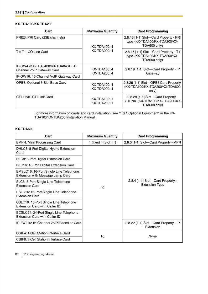
8/11/2019 TDA ProgrammingManual
http://slidepdf.com/reader/full/tda-programmingmanual 80/720
2.8 [1] Configuration
80 PC Programming Manual
For more information on cards and card installation, see "1.3.1 Optional Equipment" in the KX-TDA100/KX-TDA200 Installation Manual.
PRI23: PRI Card (23B channels)
KX-TDA100: 4
KX-TDA200: 4
2.8.13 [1-1] Slot—Card Property - PRItype (KX-TDA100/KX-TDA200/KX-
TDA600 only)
T1: T-1 CO Line Card 2.8.16 [1-1] Slot—Card Property - T1type (KX-TDA100/KX-TDA200/KX-
TDA600 only)
IP-GW4 (KX-TDA0480/KX-TDA0484): 4-Channel VoIP Gateway Card KX-TDA100: 4
KX-TDA200: 42.8.19 [1-1] Slot—Card Property - IP
GatewayIP-GW16: 16-Channel VoIP Gateway Card
OPB3: Optional 3-Slot Base CardKX-TDA100: 4KX-TDA200: 4
2.8.25 [1-1] Slot—OPB3 Card Property(KX-TDA100/KX-TDA200/KX-TDA600
only)
CTI-LINK: CTI Link CardKX-TDA100: 1
KX-TDA200: 1
2.8.28 [1-1] Slot—Card Property -CTILINK (KX-TDA100/KX-TDA200/KX-
TDA600 only)
KX-TDA600
Card Maximum Quantity Card Programming
EMPR: Main Processing Card 1 (fixed in Slot 11) 2.8.3 [1-1] Slot—Card Property - MPR
DHLC8: 8-Port Digital Hybrid Extension
Card
40
2.8.4 [1-1] Slot—Card Property -Extension Type
DLC8: 8-Port Digital Extension Card
DLC16: 16-Port Digital Extension Card
EMSLC16: 16-Port Single Line TelephoneExtension with Message Lamp Card
SLC8: 8-Port Single Line TelephoneExtension Card
ESLC16: 16-Port Single Line TelephoneExtension Card
CSLC16: 16-Port Single Line Telephone
Extension Card with Caller ID
ECSLC24: 24-Port Single Line TelephoneExtension Card with Caller ID
IP-EXT16: 16-Channel VoIP Extension Card 2.8.22 [1-1] Slot—Card Property - IPExtension
CSIF4: 4 Cell Station Interface Card16 None
CSIF8: 8 Cell Station Interface Card
KX-TDA100/KX-TDA200
Card Maximum Quantity Card Programming
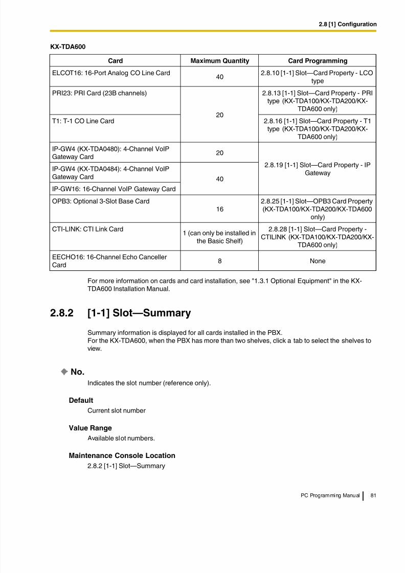
8/11/2019 TDA ProgrammingManual
http://slidepdf.com/reader/full/tda-programmingmanual 81/720
2.8 [1] Configuration
PC Programming Manual 81
For more information on cards and card installation, see "1.3.1 Optional Equipment" in the KX-TDA600 Installation Manual.
2.8.2 [1-1] Slot—Summary
Summary information is displayed for all cards installed in the PBX.For the KX-TDA600, when the PBX has more than two shelves, click a tab to select the shelves toview.
No.
Indicates the slot number (reference only).
DefaultCurrent slot number
Value Range
Available slot numbers.
Maintenance Console Location
2.8.2 [1-1] Slot—Summary
ELCOT16: 16-Port Analog CO Line Card40
2.8.10 [1-1] Slot—Card Property - LCOtype
PRI23: PRI Card (23B channels)
20
2.8.13 [1-1] Slot—Card Property - PRI
type (KX-TDA100/KX-TDA200/KX-TDA600 only)
T1: T-1 CO Line Card 2.8.16 [1-1] Slot—Card Property - T1type (KX-TDA100/KX-TDA200/KX-
TDA600 only)
IP-GW4 (KX-TDA0480): 4-Channel VoIPGateway Card
20
2.8.19 [1-1] Slot—Card Property - IPGateway
IP-GW4 (KX-TDA0484): 4-Channel VoIPGateway Card 40
IP-GW16: 16-Channel VoIP Gateway Card
OPB3: Optional 3-Slot Base Card16
2.8.25 [1-1] Slot—OPB3 Card Property(KX-TDA100/KX-TDA200/KX-TDA600
only)
CTI-LINK: CTI Link Card1 (can only be installed in
the Basic Shelf)
2.8.28 [1-1] Slot—Card Property -CTILINK (KX-TDA100/KX-TDA200/KX-
TDA600 only)
EECHO16: 16-Channel Echo CancellerCard
8 None
KX-TDA600
Card Maximum Quantity Card Programming

8/11/2019 TDA ProgrammingManual
http://slidepdf.com/reader/full/tda-programmingmanual 82/720
2.8 [1] Configuration
82 PC Programming Manual
Programming Manual References
None
Feature Manual References
None
Card Type
Indicates the type of service card installed in each slot of the PBX (reference only).Note that for MPR cards, the PBX model code is displayed in parentheses after the name.
Default
Slot 00: MPR (Main Processing Card: fixed)
Other slots: Not stored.
Value Range
Card Type for KX-TDA50:
DLC4: 4-Port Digital Extension CardDLC8: 8-Port Digital Extension Card
HLC4: 4-Port Hybrid Extension Card
PLC4: 4-Port Proprietary Extension Card
PLC8: 8-Port Proprietary Extension Card
SLC4: 4-Port Single Line Telephone Extension Card
SLC8: 8-Port Single Line Telephone Extension Card
LCOT4: 4-Port Analog CO Line Card
IP-GW4: 4-Channel VoIP Gateway Card
IP-EXT4: 4-Channel VoIP Extension Card
MSG2: 2-Channel Message CardDPH4: 4-Port Doorphone Card
ECHO8: 8-Channel Echo Canceller Card
EXT-CID: Extension Caller ID Card
SVM2: 2-Channel Simplified Voice Message Card
MPR: MPR Card
Card Type for KX-TDA100/KX-TDA200:
DHLC8: 8-Port Digital Hybrid Extension Card
DLC16: 16-Port Digital Extension Card
DLC8: 8-Port Digital Extension Card
MSLC16: 16-Port Single Line Telephone Extension with Message Lamp Card
SLC8: 8-Port Single Line Telephone Extension Card
SLC16: 16-Port Single Line Telephone Extension Card
CSLC16: 16-Port Single Line Telephone Extension Card with Caller ID
CSI/F: 4 or 8 Cell Station Interface Card
LCOT16: 16-Port Analog CO Line Card
LCOT8: 8-Port Analog CO Line Card
PRI23: PRI Card (23B channels)
8/11/2019 TDA ProgrammingManual
http://slidepdf.com/reader/full/tda-programmingmanual 83/720
2.8 [1] Configuration
PC Programming Manual 83
T1: T-1 CO Line Card
IP-GW4 (KX-TDA0480/KX-TDA0484): 4-Channel VoIP Gateway Card
OPB3: Optional 3-Slot Base Card
CTI-LINK: CTI Link Card
IP-GW16: 16-Channel VoIP Gateway Card
IP-EXT16: 16-Channel VoIP Extension Card
MPR: MPR Card
Card Type for KX-TDA600:
DHLC8: 8-Port Digital Hybrid Extension Card
DLC16: 16-Port Digital Extension Card
DLC8: 8-Port Digital Extension Card
EMSLC16: 16-Port Single Line Telephone Extension with Message Lamp Card
SLC8: 8-Port Single Line Telephone Extension Card
ESLC16: 16-Port Single Line Telephone Extension Card
CSLC16: 16-Port Single Line Telephone Extension Card with Caller ID
ECSLC24: 24-Port Single Line Telephone Extension Card with Caller IDCSI/F: 4 or 8 Cell Station Interface Card
ELCOT16: 16-Port Analog CO Line Card
PRI23: PRI Card (23B channels)
T1: T-1 CO Line Card
IP-GW4 (KX-TDA0480/KX-TDA0484): 4-Channel VoIP Gateway Card
OPB3: Optional 3-Slot Base Card
CTI-LINK: CTI Link Card
IP-GW16: 16-Channel VoIP Gateway Card
IP-EXT16: 16-Channel VoIP Extension Card
EECHO16: 16-Channel Echo Canceller CardEMPR: MPR Card
Maintenance Console Location
2.8.2 [1-1] Slot—Summary
Programming Manual References
2.8.1 [1-1] Slot
2.8.4 [1-1] Slot—Card Property - Extension Type
2.8.10 [1-1] Slot—Card Property - LCO type
2.8.13 [1-1] Slot—Card Property - PRI type (KX-TDA100/KX-TDA200/KX-TDA600 only)
2.8.16 [1-1] Slot—Card Property - T1 type (KX-TDA100/KX-TDA200/KX-TDA600 only)2.8.19 [1-1] Slot—Card Property - IP Gateway
2.8.22 [1-1] Slot—Card Property - IP Extension
2.8.25 [1-1] Slot—OPB3 Card Property (KX-TDA100/KX-TDA200/KX-TDA600 only)
2.8.28 [1-1] Slot—Card Property - CTILINK (KX-TDA100/KX-TDA200/KX-TDA600 only)
2.8.29 [1-1] Slot—Card Property - DPH type (KX-TDA50 only)
8/11/2019 TDA ProgrammingManual
http://slidepdf.com/reader/full/tda-programmingmanual 84/720
2.8 [1] Configuration
84 PC Programming Manual
Feature Manual References
None
Status
Indicates the card status (reference only).
Note that MPR card status is always displayed as "-".
Default
Slot 00: - (fixed)
Other slots: Current status
Value Range
INS: The port is in service.
OUS: The port is out of service.
Fault: The port is not communicating with the network.
Pre-Install: A card has been added to the slot.
Idle: No card in installed in the slot.
Maintenance Console Location
2.8.2 [1-1] Slot—Summary
Programming Manual References
2.8.1 [1-1] Slot
Feature Manual References
None
Version
Indicates the LPR version of the installed card (reference only).For IP-EXT16 cards, both the LPR version and the VoIP version are displayed. The LPR version isshown on the left, and the VoIP version on the right, as follows:(Example) 1.002 / 1.001For IP-EXT4 cards, only the VoIP version is displayed.
Default
Current version number
Value Range
Version number
Maintenance Console Location
2.8.2 [1-1] Slot—Summary
Programming Manual References
2.6.2 Utility—File Transfer PC to PBX (SD Card)
8/11/2019 TDA ProgrammingManual
http://slidepdf.com/reader/full/tda-programmingmanual 85/720
8/11/2019 TDA ProgrammingManual
http://slidepdf.com/reader/full/tda-programmingmanual 86/720
2.8 [1] Configuration
86 PC Programming Manual
Default
Current version
Value Range
- (not mounted), 1–15
Maintenance Console Location
2.8.3 [1-1] Slot—Card Property - MPR
Programming Manual References
None
Feature Manual References
1.18.1 Upgrading the Software
2.8.4 [1-1] Slot—Card Property - Extension Type
The property for the extension cards can be specified.
SLT Pulse Dial Mode
Selects the type of pulse dial transmission appropriate to your area.
Default
Normal
Value Range
Normal, Sweden, New Zealand
Maintenance Console Location
2.8.4 [1-1] Slot—Card Property - Extension Type
Programming Manual References
None
Feature Manual References
None
SLT Off Hook Time
Specifies the minimum length that a pulse dial sent from an SLT must be for the PBX to recognize itas an off-hook signal.
Default
160 ms
8/11/2019 TDA ProgrammingManual
http://slidepdf.com/reader/full/tda-programmingmanual 87/720
2.8 [1] Configuration
PC Programming Manual 87
Value Range
8 × n (n=3–255) ms
Maintenance Console Location
2.8.4 [1-1] Slot—Card Property - Extension Type
Programming Manual References
None
Feature Manual References
None
SLT Off Hook Guard Time
Specifies the length of guard time used for off-hook signals from SLTs, to prevent the PBX mistakingthem for pulse dials.
Default504 ms
Value Range
8 × n (n=12–63) ms
Maintenance Console Location
2.8.4 [1-1] Slot—Card Property - Extension Type
Programming Manual References
None
Feature Manual References
None
SLT Pulse Maximum Break Width
Specifies the maximum length of the break signal in a pulse dial.
Default
96 ms
Value Range8 × n (n=9–20) ms
Maintenance Console Location
2.8.4 [1-1] Slot—Card Property - Extension Type
Programming Manual References
None
8/11/2019 TDA ProgrammingManual
http://slidepdf.com/reader/full/tda-programmingmanual 88/720
2.8 [1] Configuration
88 PC Programming Manual
Feature Manual References
None
SLT Pulse Minimum Make Width
Specifies the minimum length of the make signal in a pulse dial.
Default
8 ms
Value Range
8 × n (n=1–5) ms
Maintenance Console Location
2.8.4 [1-1] Slot—Card Property - Extension Type
Programming Manual References
None
Feature Manual References
None
SLT Flash Detection
Enables the PBX to detect the flash signal sent when an SLT user presses the hookswitch or theFlash/Recall button.
Default
Enable
Value Range
Disable: The PBX disconnects the line to prevent placing the call on hold.
Enable: The PBX places the call on consultation hold.
Maintenance Console Location
2.8.4 [1-1] Slot—Card Property - Extension Type
Programming Manual References
None
Feature Manual References
1.3.7 Call Splitting
Flash Timing - Min.
Specifies the minimum length that a signal sent from an SLT must be for the PBX to recognize it asa hookswitch flash signal.
8/11/2019 TDA ProgrammingManual
http://slidepdf.com/reader/full/tda-programmingmanual 89/720
2.8 [1] Configuration
PC Programming Manual 89
Default
112 ms
Value Range
8 × n (n=3–63) ms
Maintenance Console Location
2.8.4 [1-1] Slot—Card Property - Extension Type
Programming Manual References
None
Feature Manual References
None
Flash Timing - Range
Specifies the maximum length that a signal sent from an SLT can be for the PBX to recognize it as ahookswitch flash signal.
Default
904 ms
Value Range
8 × n (n=3–191) ms
Maintenance Console Location
2.8.4 [1-1] Slot—Card Property - Extension Type
Programming Manual References
None
Feature Manual References
None
DTMF-R STD Detection Time
Specifies the minimum length that a DTMF tone must be for the PBX to recognize it as a DTMF tone.
Default30 ms
Value Range
2 × n (n=1–31) ms
Maintenance Console Location
2.8.4 [1-1] Slot—Card Property - Extension Type
8/11/2019 TDA ProgrammingManual
http://slidepdf.com/reader/full/tda-programmingmanual 90/720
2.8 [1] Configuration
90 PC Programming Manual
Programming Manual References
None
Feature Manual References
None
SLT Power Supply (KX-TDA100/KX-TDA200/KX-TDA600 only)
Selects the voltage that enables an SLT to activate the Message Waiting lamp. This setting is onlyavailable with MSLC/EMSLC cards.
Default
85 V
Value Range
85 V, 145 V
Maintenance Console Location2.8.4 [1-1] Slot—Card Property - Extension Type
Programming Manual References
None
Feature Manual References
1.11.3 Message Waiting
Optional Equipment (KX-TDA100/KX-TDA200/KX-TDA600 only)
Indicates whether an Extension Caller ID card is mounted on the SLC8 card (reference only). This isonly available with SLC8 cards.
Default
Current status
Value Range
None, Caller ID
Maintenance Console Location
2.8.4 [1-1] Slot—Card Property - Extension Type
Installation Manual References
For KX-TDA100/KX-TDA200:
2.5.6 EXT-CID Card (KX-TDA0168)
For KX-TDA600:
2.7.6 EXT-CID Card (KX-TDA0168)
8/11/2019 TDA ProgrammingManual
http://slidepdf.com/reader/full/tda-programmingmanual 91/720

8/11/2019 TDA ProgrammingManual
http://slidepdf.com/reader/full/tda-programmingmanual 92/720
2.8 [1] Configuration
92 PC Programming Manual
Feature Manual References
None
Slot
Indicates the slot position (reference only).
Default
Current slot number
Value Range
Slot number
Maintenance Console Location
2.8.5 [1-1] Slot—Port Property - Extension Port
Programming Manual References
None
Feature Manual References
None
Port
Indicates the port or channel number (reference only).
Default
Current port or channel number
Value Range
Port or channel number
Maintenance Console Location
2.8.5 [1-1] Slot—Port Property - Extension Port
Programming Manual References
None
Feature Manual References
1.5.7 Extension Port Configuration
Port Type
Indicates the port type (reference only).
Default
Current port type
8/11/2019 TDA ProgrammingManual
http://slidepdf.com/reader/full/tda-programmingmanual 93/720
2.8 [1] Configuration
PC Programming Manual 93
Value Range
DPT: DPT port (DLC)APT: APT port (PLC) (KX-TDA50 only)SLT: SLT port (SLC/ESLC/EMSLC/CSLC/ECSLC)S-Hybrid: Super Hybrid port (DHLC)Hybrid: Hybrid port (HLC) (KX-TDA50 only)S-Hybrid(SLT): XDP port of Super Hybrid port (DHLC)S-Hybrid(S-DPT): Digital XDP port of Super Hybrid port (DHLC)DPT(S-DPT): Digital XDP port of DPT port (DLC)
Maintenance Console Location
2.8.5 [1-1] Slot—Port Property - Extension Port
Programming Manual References
None
Feature Manual References
1.5.7 Extension Port Configuration
Telephone Type
Indicates the connected telephone type (reference only).The number of all connected telephones and Cell Stations can be viewed by clicking Port Type View.
Default
Current connected telephone type
Value Range
DPT (15V)/DPT (40V): DPT is connected.
APT (15V): APT is connected.DSS: DSS Console is connected.VM: VPS is connected.SLT: SLT is connected (or no telephone is connected to the Super Hybrid or SLT port).CS: CS is connected.CS-M: High-density CS is connected with its master port.CS-S1–3: High-density CS is connected with its slave port.
Maintenance Console Location
2.8.5 [1-1] Slot—Port Property - Extension Port
Programming Manual References
2.8.7 [1-1] Slot—Port Property - Extension Port—Port Type View
Feature Manual References
1.5.7 Extension Port Configuration
Connection
Indicates the port status (reference only).This column offers two ways to open the screen to select the port command as follows:
8/11/2019 TDA ProgrammingManual
http://slidepdf.com/reader/full/tda-programmingmanual 94/720
8/11/2019 TDA ProgrammingManual
http://slidepdf.com/reader/full/tda-programmingmanual 95/720
8/11/2019 TDA ProgrammingManual
http://slidepdf.com/reader/full/tda-programmingmanual 96/720
2.8 [1] Configuration
96 PC Programming Manual
Parallel Telephone Ringing
Specifies whether the sub telephone (SLT) rings at the same time as the main telephone (DPT) foran incoming call. This setting is only available when Port Type on this screen is set to S-Hybrid.
Default
Yes
Value Range
Yes, No
Maintenance Console Location
2.8.5 [1-1] Slot—Port Property - Extension Port
Programming Manual References
None
Feature Manual References
1.13.2 Paralleled Telephone
DPT Type—Type
Selects the port type.
To change the port type of an extension port, follow the steps below:
1. Set the status of the extension port to "OUS".
2. Change the port type of the extension port, then click Apply.
3. Set the status of the extension port to "INS".
When changing the port type of an extension port for which Wireless XDP has been set on the
2.11.1 [4-1-1] Wired Extension—Extension Settings screen, the Wireless XDP setting mustbe deleted first.When changing the type of a port for which one or more SDN buttons are set (except whenchanging between PC Console and Telephone), all SDN buttons customized for that device willbe deleted. When you attempt to apply the new settings, a warning message is displayedshowing the slot and port number for which SDN buttons will be deleted. If you do not wish todelete SDN buttons for this port, click Cancel.
Default
Normal
Value Range
Normal: For connecting a DPTDSS: For connecting a DSS Console (A maximum of 4 [with the KX-TDA50], 8 [with the KX-TDA100/ KX-TDA200] or 64 [with the KX-TDA600] DSS Consoles can be connected to the PBX.)VM (DPT): For connecting a Panasonic VPS through DPT IntegrationPC Console: For connecting a PC Console (A maximum of 2 [with the KX-TDA50] or 8 [with the KX-TDA100/KX-TDA200/KX-TDA600] PC Consoles can be connected to the PBX.)
Maintenance Console Location
2.8.5 [1-1] Slot—Port Property - Extension Port
8/11/2019 TDA ProgrammingManual
http://slidepdf.com/reader/full/tda-programmingmanual 97/720
2.8 [1] Configuration
PC Programming Manual 97
Programming Manual References
2.8.6 [1-1] Slot—Port Property - Extension Port—Connection Command
Feature Manual References
1.3.21 CTI (Computer Telephony Integration)
1.13.5 PC Console/PC Phone
1.19.3 Voice Mail (VM) Group
DPT Type—Location No.
Specifies the location number of the connected DSS Console or PC Console. This setting is onlyavailable when DPT Type—Type on this screen is set to DSS.Note that, depending on system traffic, there may be a limit to the number of PC Consoles that canbe supported by a single DLC/DHLC card.
When changing the location number of a DSS Console for which one or more SDN buttons are set,all SDN buttons customized for that device will be deleted. When you attempt to apply the newsettings, a warning message is displayed showing the slot and port number for which SDN buttonswill be deleted. If you do not wish to delete SDN buttons for this port, click Cancel.
Default
1
Value Range
For KX-TDA50:Location number for DSS Console: 1–4Location number for PC Console: 1, 2
For KX-TDA100/KX-TDA200:
1–8
For KX-TDA600:Location number for DSS Console: 1–64Location number for PC Console: 1–8
Maintenance Console Location
2.8.5 [1-1] Slot—Port Property - Extension Port
Programming Manual References
None
Feature Manual References
1.3.21 CTI (Computer Telephony Integration)
1.13.5 PC Console/PC Phone
DPT Type—VM Unit No.
Selects the unit number of the connected VPS. This setting is only available when DPT Type—Type on this screen is set to VM (DPT).
8/11/2019 TDA ProgrammingManual
http://slidepdf.com/reader/full/tda-programmingmanual 98/720
2.8 [1] Configuration
98 PC Programming Manual
Default
1
Value Range
For KX-TDA50:1
For KX-TDA100/KX-TDA200:
1, 2
For KX-TDA600:
1–8
Maintenance Console Location
2.8.5 [1-1] Slot—Port Property - Extension Port
Programming Manual References
None
Feature Manual References
1.19.3 Voice Mail (VM) Group
DPT Type—VM Port No.
Specifies the VM port number for the port. This setting is only available when DPT Type—Type onthis screen is set to VM (DPT).
Default
1
Value Range
For KX-TDA50:
1–4
For KX-TDA100/KX-TDA200/KX-TDA600:
1–12
Maintenance Console Location
2.8.5 [1-1] Slot—Port Property - Extension Port
Programming Manual References
None
Feature Manual References
1.19.3 Voice Mail (VM) Group
8/11/2019 TDA ProgrammingManual
http://slidepdf.com/reader/full/tda-programmingmanual 99/720
2.8 [1] Configuration
PC Programming Manual 99
Headset OFF/ON
Turns on or off the use of a headset with a DPT. This setting is only available when Port Type on thisscreen is set to DPT, DPT(S-DPT), S-Hybrid, or S-Hybrid(S-DPT).
Default
Headset OFF
Value Range
Headset OFF, Headset ON
Maintenance Console Location
2.8.5 [1-1] Slot—Port Property - Extension Port
Programming Manual References
None
Feature Manual References
1.8.3 Headset Operation
Ringing Tone
Selects the dual-tone switching pattern of the ring tone for incoming calls. This setting is only availablewhen Port Type on this screen is set to DPT, DPT(S-DPT), S-Hybrid, S-Hybrid(XDP), S-Hybrid(SLT) or S-Hybrid(S-DPT). This setting is not available for the KX-T7200, the KX-T7451,APTs, or SLTs.
Default
A
Value Range
A: 64 ms (697 Hz), 64 ms (852 Hz)B: 32 ms (697 Hz), 32 ms (852 Hz)C: 128 ms (697 Hz), 128 ms (852 Hz)D: 32 ms (697 Hz), 96 ms (852 Hz)
Maintenance Console Location
2.8.5 [1-1] Slot—Port Property - Extension Port
Programming Manual References
None
Feature Manual References
None
8/11/2019 TDA ProgrammingManual
http://slidepdf.com/reader/full/tda-programmingmanual 100/720
8/11/2019 TDA ProgrammingManual
http://slidepdf.com/reader/full/tda-programmingmanual 101/720
2.8 [1] Configuration
PC Programming Manual 101
2.8.7 [1-1] Slot—Port Property - Extension Port—Port Type View
Displays the number of connected telephones and Cell Stations (CSs).This screen can only be accessed in Interactive mode.
TypeIndicates the types of telephone (reference only).
Default
Not applicable.
Value Range
New-DPT (KX-T7600 series DPTs), Old-DPT (DPTs other than KX-T7600 series), APT, SLT, DSSConsole, VM, Other, CS, High-density CS, IP-EXT
Maintenance Console Location
2.8.7 [1-1] Slot—Port Property - Extension Port—Port Type View
Programming Manual References
2.8.5 [1-1] Slot—Port Property - Extension Port
Feature Manual References
None
Total Count
Indicates the total number of each type of telephone and CS connected to the PBX (reference only).
With the KX-TDA50, CSs are counted on the basis of the number of extension ports to which they areconnected; with the KX-TDA100/KX-TDA200/KX-TDA600, CSs are counted on the basis of thenumber of CSIF ports in service plus the number of extension ports to which CSs are connected.
Default
Not applicable.
Value Range
Not applicable.
Maintenance Console Location
2.8.7 [1-1] Slot—Port Property - Extension Port—Port Type View
Programming Manual References
2.8.5 [1-1] Slot—Port Property - Extension Port
2.8.8 [1-1] Slot—Port Property - CSI/F Port (KX-TDA100/KX-TDA200/KX-TDA600 only)
Feature Manual References
None
8/11/2019 TDA ProgrammingManual
http://slidepdf.com/reader/full/tda-programmingmanual 102/720
2.8 [1] Configuration
102 PC Programming Manual
2.8.8 [1-1] Slot—Port Property - CSI/F Port (KX-TDA100/KX-TDA200/KX-TDA600 only)
The status of the CSIF ports can be referred to, or set to INS (in-service) or OUS (out-of-service).To change the status of ports, click Command.
Shelf (KX-TDA600 only)
Indicates the shelf position (reference only).
Default
Current shelf number
Value Range
Shelf number
Maintenance Console Location
2.8.8 [1-1] Slot—Port Property - CSI/F Port (KX-TDA100/KX-TDA200/KX-TDA600 only)
Programming Manual References
None
Feature Manual References
None
Slot
Indicates the slot position (reference only).
Default
Current slot number
Value Range
Slot number
Maintenance Console Location
2.8.8 [1-1] Slot—Port Property - CSI/F Port (KX-TDA100/KX-TDA200/KX-TDA600 only)
Programming Manual References
None
Feature Manual References
None
Port
Indicates the port number (reference only).
8/11/2019 TDA ProgrammingManual
http://slidepdf.com/reader/full/tda-programmingmanual 103/720
8/11/2019 TDA ProgrammingManual
http://slidepdf.com/reader/full/tda-programmingmanual 104/720
2.8 [1] Configuration
104 PC Programming Manual
Value Range
Max. 20 characters
Maintenance Console Location
2.8.8 [1-1] Slot—Port Property - CSI/F Port (KX-TDA100/KX-TDA200/KX-TDA600 only)
Programming Manual References
None
Feature Manual References
None
2.8.9 [1-1] Slot—Port Property - CSI/F Port—ConnectionCommand (KX-TDA100/KX-TDA200/KX-TDA600 only)
Commands for the CSIF ports can be programmed.
INS
Puts the Cell Station (CS) in service.
Default
Not applicable.
Value Range
Not applicable.
Maintenance Console Location
2.8.9 [1-1] Slot—Port Property - CSI/F Port—Connection Command (KX-TDA100/KX-TDA200/KX-TDA600 only)
Programming Manual References
2.8.8 [1-1] Slot—Port Property - CSI/F Port (KX-TDA100/KX-TDA200/KX-TDA600 only)
Feature Manual References
None
OUSTakes the CS out of service. This enables a temporary non-use of the CS, for example, for thepurpose of repair.
Default
Not applicable.
Value Range
Not applicable.
8/11/2019 TDA ProgrammingManual
http://slidepdf.com/reader/full/tda-programmingmanual 105/720
2.8 [1] Configuration
PC Programming Manual 105
Maintenance Console Location
2.8.9 [1-1] Slot—Port Property - CSI/F Port—Connection Command (KX-TDA100/KX-TDA200/KX-TDA600 only)
Programming Manual References
2.8.8 [1-1] Slot—Port Property - CSI/F Port (KX-TDA100/KX-TDA200/KX-TDA600 only)
Feature Manual References
None
2.8.10 [1-1] Slot—Card Property - LCO type
The properties of the analog CO line cards can be specified.
Outgoing Guard Time
Specifies the length of time after a CO line is disconnected, during which the PBX cannot seize theline.
Default
3 s
Value Range
3–6 s
Maintenance Console Location
2.8.10 [1-1] Slot—Card Property - LCO type
Programming Manual References
None
Feature Manual References
None
First Dial Timer (CO)
Specifies the minimum time that the PBX waits after seizing a CO line, before sending the dialed digitsto the telephone company. This allows the telephone company to have enough time to accept thedialed digits correctly.
Default
1.0 s
Value Range
0.5 × n (n=1–16) s
8/11/2019 TDA ProgrammingManual
http://slidepdf.com/reader/full/tda-programmingmanual 106/720
2.8 [1] Configuration
106 PC Programming Manual
Maintenance Console Location
2.8.10 [1-1] Slot—Card Property - LCO type
Programming Manual References
None
Feature Manual References
None
CO Feed Back Tone
Specifies whether the pulse feedback tone is turned on or not. For outgoing CO line calls, audibletones can be heard as the dialed number is sent out, which informs the extension user that thenumber has been dialed.
Default
Yes
Value Range
No, Yes
Maintenance Console Location
2.8.10 [1-1] Slot—Card Property - LCO type
Programming Manual References
None
Feature Manual References
None
Bell Detection—Bell Start Detection Timer
Specifies the minimum length of a bell signal that can be recognized by the PBX as the bell signalsent from the telephone company, before the PBX detects an arriving call.
Default
144 ms
Value Range
24 × n (n=1–50) ms
Maintenance Console Location
2.8.10 [1-1] Slot—Card Property - LCO type
Programming Manual References
None
8/11/2019 TDA ProgrammingManual
http://slidepdf.com/reader/full/tda-programmingmanual 107/720
2.8 [1] Configuration
PC Programming Manual 107
Feature Manual References
None
Bell Detection—Bell Off Detection Timer
Specifies the duration of the bell off detection timer. If the PBX receives no bell signal from the
telephone company for the length of time specified here, the PBX treats the call as lost.
Default
6.0 s
Value Range
1.0 s–15.0 s
Maintenance Console Location
2.8.10 [1-1] Slot—Card Property - LCO type
Programming Manual ReferencesNone
Feature Manual References
None
Pulse / DTMF Dial—DTMF Inter-digit Pause
Specifies the length of the DTMF inter-digit pause. This allows the telephone company to haveenough time to accept the dialed digits correctly.
Default112 ms
Value Range
64 + 16 × n (n=0–11) ms
Maintenance Console Location
2.8.10 [1-1] Slot—Card Property - LCO type
Programming Manual References
None
Feature Manual References
None
Pulse / DTMF Dial—Pulse Inter-digit Pause
Specifies the length of the pulse inter-digit pause. This allows the telephone company to have enoughtime to accept the dialed digits correctly.
8/11/2019 TDA ProgrammingManual
http://slidepdf.com/reader/full/tda-programmingmanual 108/720
2.8 [1] Configuration
108 PC Programming Manual
Default
830 ms
Value Range
630 ms, 830 ms, 1030 ms
Maintenance Console Location
2.8.10 [1-1] Slot—Card Property - LCO type
Programming Manual References
None
Feature Manual References
None
Low Speed Pulse Dial—Pulse % Break
Specifies the % break for a low speed pulse dial. This is the ratio between the break (on-hook) signaland make (off-hook) signal in a pulse dial.
Default
60 %
Value Range
Other, 60 %, 67 %
Maintenance Console Location
2.8.10 [1-1] Slot—Card Property - LCO type
Programming Manual References
2.8.11 [1-1] Slot—Port Property - LCO Port
Feature Manual References
None
Low Speed Pulse Dial—Break Width
Specifies the maximum length of the break signal in a low speed pulse dial. Low Speed Pulse Dial—Pulse % Break on this screen determines the value that can be specified here.
Default
60 ms
Value Range
4 × n (n=6–20) ms
Maintenance Console Location
2.8.10 [1-1] Slot—Card Property - LCO type
8/11/2019 TDA ProgrammingManual
http://slidepdf.com/reader/full/tda-programmingmanual 109/720
2.8 [1] Configuration
PC Programming Manual 109
Programming Manual References
2.8.11 [1-1] Slot—Port Property - LCO Port
Feature Manual References
None
Low Speed Pulse Dial—Make Width
Specifies the minimum length of the make signal in a low speed pulse dial. Low Speed Pulse Dial—Pulse % Break on this screen determines the value that can be specified here.
Default
40 ms
Value Range
4 × n (n=3–15) ms
Maintenance Console Location2.8.10 [1-1] Slot—Card Property - LCO type
Programming Manual References
2.8.11 [1-1] Slot—Port Property - LCO Port
Feature Manual References
None
High Speed Pulse Dial—Pulse % Break
Specifies the % break for a high speed pulse dial. This is the ratio between the break (on-hook) signaland make (off-hook) signal in a pulse dial.
Default
60 %
Value Range
Other, 60 %, 67 %
Maintenance Console Location
2.8.10 [1-1] Slot—Card Property - LCO type
Programming Manual References
2.8.11 [1-1] Slot—Port Property - LCO Port
Feature Manual References
None
8/11/2019 TDA ProgrammingManual
http://slidepdf.com/reader/full/tda-programmingmanual 110/720
2.8 [1] Configuration
110 PC Programming Manual
High Speed Pulse Dial—Break Width
Specifies the maximum length of the break signal in a high speed pulse dial. High Speed Pulse
Dial—Pulse % Break on this screen determines the value that can be specified here.
Default
32 ms
Value Range
4 × n (n=4–18) ms
Maintenance Console Location
2.8.10 [1-1] Slot—Card Property - LCO type
Programming Manual References
2.8.11 [1-1] Slot—Port Property - LCO Port
Feature Manual References
None
High Speed Pulse Dial—Make Width
Specifies the minimum length of the make signal in a high speed pulse dial. High Speed Pulse Dial—
Pulse % Break on this screen determines the value that can be specified here.
Default
20 ms
Value Range
4 × n (n=3–15) ms
Maintenance Console Location
2.8.10 [1-1] Slot—Card Property - LCO type
Programming Manual References
2.8.11 [1-1] Slot—Port Property - LCO Port
Feature Manual References
None
Pulse Type
Selects the type of pulse dial transmission appropriate to your area.
Default
Normal

8/11/2019 TDA ProgrammingManual
http://slidepdf.com/reader/full/tda-programmingmanual 111/720
2.8 [1] Configuration
PC Programming Manual 111
Value Range
Normal, Sweden, New Zealand
Maintenance Console Location
2.8.10 [1-1] Slot—Card Property - LCO type
Programming Manual References
None
Feature Manual References
None
Option Card Equipment—Option 1 and Option 2
Indicates the type of the card that is installed on the LCOT/ELCOT card (reference only).
Default
Current option card type
Value Range
None, Caller ID Card
Maintenance Console Location
2.8.10 [1-1] Slot—Card Property - LCO type
Programming Manual References
2.8.11 [1-1] Slot—Port Property - LCO Port—Caller ID Detection
Feature Manual References1.3.1 Caller ID
Caller ID—Caller ID Signaling
Selects the type of Caller ID signaling provided by the telephone company.
Default
FSK
Value Range
FSK, FSK (with Visual Caller ID), DTMF
Maintenance Console Location
2.8.10 [1-1] Slot—Card Property - LCO type
Programming Manual References
None
8/11/2019 TDA ProgrammingManual
http://slidepdf.com/reader/full/tda-programmingmanual 112/720
8/11/2019 TDA ProgrammingManual
http://slidepdf.com/reader/full/tda-programmingmanual 113/720
2.8 [1] Configuration
PC Programming Manual 113
Value Range
Length + Timer, Timer
Maintenance Console Location
2.8.10 [1-1] Slot—Card Property - LCO type
Programming Manual References
None
Feature Manual References
1.3.1 Caller ID
Caller ID—Caller ID (FSK) Header Examination
Enables the PBX to check the header of received Caller ID information. To enable this setting, CallerID—Caller ID Signaling on this screen should be set to FSK.
DefaultEnable
Value Range
Disable, Enable
Maintenance Console Location
2.8.10 [1-1] Slot—Card Property - LCO type
Programming Manual References
None
Feature Manual References
1.3.1 Caller ID
Caller ID—Caller ID (FSK) Detection Start Timer
Specifies the length of time that the PBX waits before attempting to detect Caller ID information, afterreceiving a call. To enable this setting, Caller ID—Caller ID Signaling on this screen should be setto FSK.
Default
80 ms
Value Range
None, 80 × n (n=1–15) ms
Maintenance Console Location
2.8.10 [1-1] Slot—Card Property - LCO type
8/11/2019 TDA ProgrammingManual
http://slidepdf.com/reader/full/tda-programmingmanual 114/720
8/11/2019 TDA ProgrammingManual
http://slidepdf.com/reader/full/tda-programmingmanual 115/720
8/11/2019 TDA ProgrammingManual
http://slidepdf.com/reader/full/tda-programmingmanual 116/720
2.8 [1] Configuration
116 PC Programming Manual
Default
Current status
Value Range
INS: The port is in service.
OUS: The port is out of service.
Maintenance Console Location
2.8.11 [1-1] Slot—Port Property - LCO Port
Programming Manual References
2.8.12 [1-1] Slot—Port Property - LCO Port—Connection Command
Feature Manual References
None
Dialing ModeSelects the type of signal used to dial out to the analog CO line.
Default
DTMF
Value Range
DTMF, Pulse
Maintenance Console Location
2.8.11 [1-1] Slot—Port Property - LCO Port
Programming Manual References
None
Feature Manual References
1.4.2 Dial Mode Selection
CPC Signal Detection Time—Outgoing, Incoming
Specifies the length of time required by the PBX to detect a CPC signal on outgoing or incoming COline calls before disconnecting the line. When None is selected here, the line will not be disconnected
when a CPC signal is not detected.
Default
400 ms
Value Range
None, 6.5 ms, 8 × n (n=1–112) ms
8/11/2019 TDA ProgrammingManual
http://slidepdf.com/reader/full/tda-programmingmanual 117/720
2.8 [1] Configuration
PC Programming Manual 117
Maintenance Console Location
2.8.11 [1-1] Slot—Port Property - LCO Port
Programming Manual References
None
Feature Manual References
1.3.20 CPC (Calling Party Control) Signal Detection
DTMF Width
Selects the length of the DTMF tone sent to the analog CO line.
Default
80 ms
Value Range
80 ms, 160 ms
Maintenance Console Location
2.8.11 [1-1] Slot—Port Property - LCO Port
Programming Manual References
None
Feature Manual References
None
Pulse Speed
Selects the speed at which pulse dials are sent to the analog CO line.
Default
Low
Value Range
Low, High
Maintenance Console Location
2.8.11 [1-1] Slot—Port Property - LCO Port
Programming Manual References
None
Feature Manual References
None
8/11/2019 TDA ProgrammingManual
http://slidepdf.com/reader/full/tda-programmingmanual 118/720
2.8 [1] Configuration
118 PC Programming Manual
Reverse Detection (KX-TDA100/KX-TDA200/KX-TDA600 only)
Selects the type of CO line call for which the reverse signal from the telephone company is detected.
Default
Disable
Value Range
Disable: For no CO line callOutgoing: For outgoing CO line calls onlyBoth Call: For both outgoing and incoming CO line calls
Maintenance Console Location
2.8.11 [1-1] Slot—Port Property - LCO Port
Programming Manual References
None
Feature Manual ReferencesNone
Caller ID Detection
Enables the PBX to detect a Caller ID signal from the analog CO line.
Default
Enable
Value Range
Disable, Enable
Maintenance Console Location
2.8.11 [1-1] Slot—Port Property - LCO Port
Programming Manual References
2.8.10 [1-1] Slot—Card Property - LCO type
Feature Manual References
1.3.1 Caller ID
Paytone Detection (KX-TDA100/KX-TDA200/KX-TDA600 only)
Enables the PBX to receive a pay tone signal from the telephone company.
Default
Disable
8/11/2019 TDA ProgrammingManual
http://slidepdf.com/reader/full/tda-programmingmanual 119/720
8/11/2019 TDA ProgrammingManual
http://slidepdf.com/reader/full/tda-programmingmanual 120/720
2.8 [1] Configuration
120 PC Programming Manual
Programming Manual References
None
Feature Manual References
1.5.1 EFA (External Feature Access)
Disconnect Time
Specifies the length of time after a CO line is disconnected, during which the PBX cannot seize theline.
Default
1.5 s
Value Range
0.5 s, 1.5 s, 2.0 s, 4.0 s, 12.0 s
Maintenance Console Location2.8.11 [1-1] Slot—Port Property - LCO Port
Programming Manual References
None
Feature Manual References
1.6.2 Flash/Recall/Terminate
2.8.12 [1-1] Slot—Port Property - LCO Port—Connection
Command
Commands for the LCO ports can be programmed.
INS
Puts the port in service.
Default
Not applicable.
Value RangeNot applicable.
Maintenance Console Location
2.8.12 [1-1] Slot—Port Property - LCO Port—Connection Command
Programming Manual References
2.8.11 [1-1] Slot—Port Property - LCO Port
8/11/2019 TDA ProgrammingManual
http://slidepdf.com/reader/full/tda-programmingmanual 121/720
2.8 [1] Configuration
PC Programming Manual 121
Feature Manual References
None
OUS
Takes the port out of service. This enables a temporary non-use of the port, for example, for the
purpose of repair.
Default
Not applicable.
Value Range
Not applicable.
Maintenance Console Location
2.8.12 [1-1] Slot—Port Property - LCO Port—Connection Command
Programming Manual References2.8.11 [1-1] Slot—Port Property - LCO Port
Feature Manual References
None
2.8.13 [1-1] Slot—Card Property - PRI type (KX-TDA100/KX-TDA200/KX-TDA600 only)
The properties of the PRI card can be specified.
ISDN CO / QSIG Master / QSIG Slave—T200
Specifies the maximum time that the PBX waits for a reply after sending the L2 command to ISDN.
Default
10 × 100 ms
Value Range
0–600 × 100 ms
Maintenance Console Location2.8.13 [1-1] Slot—Card Property - PRI type (KX-TDA100/KX-TDA200/KX-TDA600 only)
Programming Manual References
None
Feature Manual References
None
8/11/2019 TDA ProgrammingManual
http://slidepdf.com/reader/full/tda-programmingmanual 122/720
2.8 [1] Configuration
122 PC Programming Manual
ISDN CO / QSIG Master / QSIG Slave—T202
Specifies the maximum time that the PBX waits for a reply after resending the request to use an ISDNline as a TIE line.
Default
20 × 100 ms
Value Range
0–600 × 100 ms
Maintenance Console Location
2.8.13 [1-1] Slot—Card Property - PRI type (KX-TDA100/KX-TDA200/KX-TDA600 only)
Programming Manual References
None
Feature Manual References
1.13.13 PRIVATE NETWORK FEATURES
ISDN CO / QSIG Master / QSIG Slave—T203
Specifies the length of time to detect no communication status of L2.
Default
100 × 100 ms
Value Range
0–600 × 100 ms
Maintenance Console Location
2.8.13 [1-1] Slot—Card Property - PRI type (KX-TDA100/KX-TDA200/KX-TDA600 only)
Programming Manual References
None
Feature Manual References
None
ISDN CO / QSIG Master / QSIG Slave—T301Specifies the maximum time that the PBX waits for a reply after making a call to ISDN.
Default
0 × 100 ms
Value Range
0–18000 × 100 ms
8/11/2019 TDA ProgrammingManual
http://slidepdf.com/reader/full/tda-programmingmanual 123/720
2.8 [1] Configuration
PC Programming Manual 123
Maintenance Console Location
2.8.13 [1-1] Slot—Card Property - PRI type (KX-TDA100/KX-TDA200/KX-TDA600 only)
Programming Manual References
None
Feature Manual References
None
ISDN CO / QSIG Master / QSIG Slave—T302
Specifies the maximum time allowed between each digit on an incoming call. Applies to overlapreceiving.
Default
150 × 100 ms
Value Range0–600 × 100 ms
Maintenance Console Location
2.8.13 [1-1] Slot—Card Property - PRI type (KX-TDA100/KX-TDA200/KX-TDA600 only)
Programming Manual References
None
Feature Manual References
None
ISDN CO / QSIG Master / QSIG Slave—T303
Specifies the maximum time that the PBX waits for a reply after sending the SETUP (call setting)message to ISDN.
Default
40 × 100 ms
Value Range
0–600 × 100 ms
Maintenance Console Location
2.8.13 [1-1] Slot—Card Property - PRI type (KX-TDA100/KX-TDA200/KX-TDA600 only)
Programming Manual References
None
Feature Manual References
None

8/11/2019 TDA ProgrammingManual
http://slidepdf.com/reader/full/tda-programmingmanual 124/720
2.8 [1] Configuration
124 PC Programming Manual
ISDN CO / QSIG Master / QSIG Slave—T304
Specifies the maximum time allowed between each digit on an outgoing call. Applies to overlapsending.
Default
300 × 100 ms
Value Range
0–3000 × 100 ms
Maintenance Console Location
2.8.13 [1-1] Slot—Card Property - PRI type (KX-TDA100/KX-TDA200/KX-TDA600 only)
Programming Manual References
None
Feature Manual References
None
ISDN CO / QSIG Master / QSIG Slave—T305
Specifies the maximum time that the PBX waits for a reply after sending the DISC (disconnection)message to ISDN.
Default
300 × 100 ms
Value Range
0–3000 × 100 ms
Maintenance Console Location
2.8.13 [1-1] Slot—Card Property - PRI type (KX-TDA100/KX-TDA200/KX-TDA600 only)
Programming Manual References
None
Feature Manual References
None
ISDN CO / QSIG Master / QSIG Slave—T308
Specifies the maximum time that the PBX waits for a reply after receiving the Release message fromISDN.
Default
40 × 100 ms
8/11/2019 TDA ProgrammingManual
http://slidepdf.com/reader/full/tda-programmingmanual 125/720
2.8 [1] Configuration
PC Programming Manual 125
Value Range
0–600 × 100 ms
Maintenance Console Location
2.8.13 [1-1] Slot—Card Property - PRI type (KX-TDA100/KX-TDA200/KX-TDA600 only)
Programming Manual References
None
Feature Manual References
None
ISDN CO / QSIG Master / QSIG Slave—T309
Specifies the length of time that the PBX tries to disconnect the data link, before disconnecting thecall.
Default120 × 100 ms
Value Range
0–3000 × 100 ms
Maintenance Console Location
2.8.13 [1-1] Slot—Card Property - PRI type (KX-TDA100/KX-TDA200/KX-TDA600 only)
Programming Manual References
None
Feature Manual References
None
ISDN CO / QSIG Master / QSIG Slave—T310
Specifies the maximum time that the PBX waits for a continuance message after receiving theIncoming Call Proceeding message.
Default
1100 × 100 ms
Value Range
0–3000 × 100 ms
Maintenance Console Location
2.8.13 [1-1] Slot—Card Property - PRI type (KX-TDA100/KX-TDA200/KX-TDA600 only)
Programming Manual References
None
8/11/2019 TDA ProgrammingManual
http://slidepdf.com/reader/full/tda-programmingmanual 126/720
2.8 [1] Configuration
126 PC Programming Manual
Feature Manual References
None
ISDN CO / QSIG Master / QSIG Slave—T313
Specifies the maximum time that the PBX waits for a reply after sending the Connect message.
Default
40 × 100 ms
Value Range
0–600 × 100 ms
Maintenance Console Location
2.8.13 [1-1] Slot—Card Property - PRI type (KX-TDA100/KX-TDA200/KX-TDA600 only)
Programming Manual References
None
Feature Manual References
None
ISDN CO / QSIG Master / QSIG Slave—T316
Specifies the maximum time that the PBX waits for a reply after sending the Restart message.
Default
0 × 100 ms
Value Range
0–3000 × 100 ms
Maintenance Console Location
2.8.13 [1-1] Slot—Card Property - PRI type (KX-TDA100/KX-TDA200/KX-TDA600 only)
Programming Manual References
None
Feature Manual References
None
ISDN CO / QSIG Master / QSIG Slave—T318
Specifies the maximum time that the PBX waits for a reply after sending the Resume message.
Default
0 × 100 ms
8/11/2019 TDA ProgrammingManual
http://slidepdf.com/reader/full/tda-programmingmanual 127/720
2.8 [1] Configuration
PC Programming Manual 127
Value Range
0–600 × 100 ms
Maintenance Console Location
2.8.13 [1-1] Slot—Card Property - PRI type (KX-TDA100/KX-TDA200/KX-TDA600 only)
Programming Manual References
None
Feature Manual References
None
ISDN CO / QSIG Master / QSIG Slave—T319
Specifies the maximum time that the PBX waits for a reply after sending the Suspend message.
Default
0 × 100 ms
Value Range
0–600 × 100 ms
Maintenance Console Location
2.8.13 [1-1] Slot—Card Property - PRI type (KX-TDA100/KX-TDA200/KX-TDA600 only)
Programming Manual References
None
Feature Manual ReferencesNone
ISDN CO / QSIG Master / QSIG Slave—T322
Specifies the maximum time that the PBX waits for a reply after sending the Status enquiry message.
Default
40 × 100 ms
Value Range
0–600 × 100 ms
Maintenance Console Location
2.8.13 [1-1] Slot—Card Property - PRI type (KX-TDA100/KX-TDA200/KX-TDA600 only)
Programming Manual References
None
8/11/2019 TDA ProgrammingManual
http://slidepdf.com/reader/full/tda-programmingmanual 128/720
2.8 [1] Configuration
128 PC Programming Manual
Feature Manual References
None
ISDN CO / QSIG Master / QSIG Slave—T3D3
Specifies the length of time that the PBX tries to establish L2 in "Permanent" mode.
Default
100 × 100 ms
Value Range
0–3000 × 100 ms
Maintenance Console Location
2.8.13 [1-1] Slot—Card Property - PRI type (KX-TDA100/KX-TDA200/KX-TDA600 only)
Programming Manual References
None
Feature Manual References
None
ISDN CO / QSIG Master / QSIG Slave—T3D9
Specifies the length of time that the PBX tries to disconnect L2 in "Call by Call" mode.
Default
200 × 100 ms
Value Range
0–3000 × 100 ms
Maintenance Console Location
2.8.13 [1-1] Slot—Card Property - PRI type (KX-TDA100/KX-TDA200/KX-TDA600 only)
Programming Manual References
None
Feature Manual References
None
ISDN Extension—T200
Specifies the maximum time that the PBX waits for a reply after sending the L2 command to ISDN.
Default
10 × 100 ms

8/11/2019 TDA ProgrammingManual
http://slidepdf.com/reader/full/tda-programmingmanual 129/720
2.8 [1] Configuration
PC Programming Manual 129
Value Range
0–600 × 100 ms
Maintenance Console Location
2.8.13 [1-1] Slot—Card Property - PRI type (KX-TDA100/KX-TDA200/KX-TDA600 only)
Programming Manual References
None
Feature Manual References
None
ISDN Extension—T201
Specifies the maximum time that the PBX waits for a reply after resending the TEI check request toISDN.
Default10 × 100 ms
Value Range
0–600 × 100 ms
Maintenance Console Location
2.8.13 [1-1] Slot—Card Property - PRI type (KX-TDA100/KX-TDA200/KX-TDA600 only)
Programming Manual References
None
Feature Manual References
None
ISDN Extension—T203
Specifies the length of time to detect no communication status of L2.
Default
100 × 100 ms
Value Range0–600 × 100 ms
Maintenance Console Location
2.8.13 [1-1] Slot—Card Property - PRI type (KX-TDA100/KX-TDA200/KX-TDA600 only)
Programming Manual References
None
8/11/2019 TDA ProgrammingManual
http://slidepdf.com/reader/full/tda-programmingmanual 130/720
2.8 [1] Configuration
130 PC Programming Manual
Feature Manual References
None
ISDN Extension—T301
Specifies the maximum time that the PBX waits for a reply after making a call to ISDN.
Default
0 × 100 ms
Value Range
0–18000 × 100 ms
Maintenance Console Location
2.8.13 [1-1] Slot—Card Property - PRI type (KX-TDA100/KX-TDA200/KX-TDA600 only)
Programming Manual References
None
Feature Manual References
None
ISDN Extension—T302
Specifies the maximum time allowed between each digit on an incoming call. Applies to overlapreceiving.
Default
150 × 100 ms
Value Range
0–600 × 100 ms
Maintenance Console Location
2.8.13 [1-1] Slot—Card Property - PRI type (KX-TDA100/KX-TDA200/KX-TDA600 only)
Programming Manual References
None
Feature Manual ReferencesNone
ISDN Extension—T303
Specifies the maximum time that the PBX waits for a reply after sending the SETUP (call setting)message to ISDN.
8/11/2019 TDA ProgrammingManual
http://slidepdf.com/reader/full/tda-programmingmanual 131/720
2.8 [1] Configuration
PC Programming Manual 131
Default
40 × 100 ms
Value Range
0–600 × 100 ms
Maintenance Console Location
2.8.13 [1-1] Slot—Card Property - PRI type (KX-TDA100/KX-TDA200/KX-TDA600 only)
Programming Manual References
None
Feature Manual References
None
ISDN Extension—T304
Specifies the maximum time allowed between each digit on an outgoing call. Applies to overlapsending.
Default
200 × 100 ms
Value Range
0–3000 × 100 ms
Maintenance Console Location
2.8.13 [1-1] Slot—Card Property - PRI type (KX-TDA100/KX-TDA200/KX-TDA600 only)
Programming Manual References
None
Feature Manual References
None
ISDN Extension—T305
Specifies the maximum time that the PBX waits for a reply after sending the DISC (disconnection)message to ISDN.
Default
300 × 100 ms
Value Range
0–3000 × 100 ms
Maintenance Console Location
2.8.13 [1-1] Slot—Card Property - PRI type (KX-TDA100/KX-TDA200/KX-TDA600 only)

8/11/2019 TDA ProgrammingManual
http://slidepdf.com/reader/full/tda-programmingmanual 132/720
2.8 [1] Configuration
132 PC Programming Manual
Programming Manual References
None
Feature Manual References
None
ISDN Extension—T306
Specifies the maximum time that the PBX waits for a reply after sending the DISC (disconnection)message to ISDN. This setting is used when inband tones are supplied.
Default
300 × 100 ms
Value Range
0–3000 × 100 ms
Maintenance Console Location2.8.13 [1-1] Slot—Card Property - PRI type (KX-TDA100/KX-TDA200/KX-TDA600 only)
Programming Manual References
None
Feature Manual References
None
ISDN Extension—T307
Specifies the maximum time that the PBX maintains a suspended call, before restarting.
Default
1800 × 100 ms
Value Range
0–6000 × 100 ms
Maintenance Console Location
2.8.13 [1-1] Slot—Card Property - PRI type (KX-TDA100/KX-TDA200/KX-TDA600 only)
Programming Manual ReferencesNone
Feature Manual References
None
8/11/2019 TDA ProgrammingManual
http://slidepdf.com/reader/full/tda-programmingmanual 133/720
2.8 [1] Configuration
PC Programming Manual 133
ISDN Extension—T308
Specifies the maximum time that the PBX waits for a reply after receiving the Release message fromISDN.
Default
40 × 100 ms
Value Range
0–600 × 100 ms
Maintenance Console Location
2.8.13 [1-1] Slot—Card Property - PRI type (KX-TDA100/KX-TDA200/KX-TDA600 only)
Programming Manual References
None
Feature Manual References
None
ISDN Extension—T309
Specifies the length of time that the PBX tries to disconnect the data link, before disconnecting thecall.
Default
120 × 100 ms
Value Range
0–3000 × 100 ms
Maintenance Console Location
2.8.13 [1-1] Slot—Card Property - PRI type (KX-TDA100/KX-TDA200/KX-TDA600 only)
Programming Manual References
None
Feature Manual References
None
ISDN Extension—T310
Specifies the maximum time that the PBX waits for a reply after receiving the Incoming CallProceeding message.
Default
400 × 100 ms
8/11/2019 TDA ProgrammingManual
http://slidepdf.com/reader/full/tda-programmingmanual 134/720
2.8 [1] Configuration
134 PC Programming Manual
Value Range
0–3000 × 100 ms
Maintenance Console Location
2.8.13 [1-1] Slot—Card Property - PRI type (KX-TDA100/KX-TDA200/KX-TDA600 only)
Programming Manual References
None
Feature Manual References
None
ISDN Extension—T312
Specifies the maximum time that the PBX waits for a reply after sending the SETUP (call setting)message to ISDN.
Default60 × 100 ms
Value Range
0–600 × 100 ms
Maintenance Console Location
2.8.13 [1-1] Slot—Card Property - PRI type (KX-TDA100/KX-TDA200/KX-TDA600 only)
Programming Manual References
None
Feature Manual References
None
ISDN Extension—T316
Specifies the maximum time that the PBX waits for a reply after sending the Restart message.
Default
0 × 100 ms
Value Range0–3000 × 100 ms
Maintenance Console Location
2.8.13 [1-1] Slot—Card Property - PRI type (KX-TDA100/KX-TDA200/KX-TDA600 only)
Programming Manual References
None
8/11/2019 TDA ProgrammingManual
http://slidepdf.com/reader/full/tda-programmingmanual 135/720
2.8 [1] Configuration
PC Programming Manual 135
Feature Manual References
None
ISDN Extension—T320
Specifies the maximum time that the PBX waits for packet protocol.
Default
0 × 100 ms
Value Range
0–3000 × 100 ms
Maintenance Console Location
2.8.13 [1-1] Slot—Card Property - PRI type (KX-TDA100/KX-TDA200/KX-TDA600 only)
Programming Manual References
None
Feature Manual References
None
ISDN Extension—T322
Specifies the maximum time that the PBX waits for a reply after sending the Status enquiry message.
Default
40 × 100 ms
Value Range
0–600 × 100 ms
Maintenance Console Location
2.8.13 [1-1] Slot—Card Property - PRI type (KX-TDA100/KX-TDA200/KX-TDA600 only)
Programming Manual References
None
Feature Manual References
None
ISDN Extension—T3D3
Specifies the length of time that the PBX tries to establish L2 in "Permanent" mode.
Default
300 × 100 ms
8/11/2019 TDA ProgrammingManual
http://slidepdf.com/reader/full/tda-programmingmanual 136/720
2.8 [1] Configuration
136 PC Programming Manual
Value Range
0–3000 × 100 ms
Maintenance Console Location
2.8.13 [1-1] Slot—Card Property - PRI type (KX-TDA100/KX-TDA200/KX-TDA600 only)
Programming Manual References
None
Feature Manual References
None
ISDN Extension—T3D9
Specifies the length of time that the PBX tries to disconnect L2 in "Call by Call" mode.
Default
200 × 100 ms
Value Range
0–3000 × 100 ms
Maintenance Console Location
2.8.13 [1-1] Slot—Card Property - PRI type (KX-TDA100/KX-TDA200/KX-TDA600 only)
Programming Manual References
None
Feature Manual ReferencesNone
2.8.14 [1-1] Slot—Port Property - PRI Port (KX-TDA100/KX-TDA200/KX-TDA600 only)
Various settings can be programmed for each PRI port.
Main
Shelf (KX-TDA600 only)
Indicates the shelf position (reference only).
Default
Current shelf number
8/11/2019 TDA ProgrammingManual
http://slidepdf.com/reader/full/tda-programmingmanual 137/720
2.8 [1] Configuration
PC Programming Manual 137
Value Range
Shelf number
Maintenance Console Location
2.8.14 [1-1] Slot—Port Property - PRI Port (KX-TDA100/KX-TDA200/KX-TDA600 only)
Programming Manual References
None
Feature Manual References
None
Slot
Indicates the slot position (reference only).
Default
Current slot number
Value Range
Slot number
Maintenance Console Location
2.8.14 [1-1] Slot—Port Property - PRI Port (KX-TDA100/KX-TDA200/KX-TDA600 only)
Programming Manual References
None
Feature Manual ReferencesNone
Port
Indicates the port number (reference only).
Default
Current port number
Value Range
Port number
Maintenance Console Location
2.8.14 [1-1] Slot—Port Property - PRI Port (KX-TDA100/KX-TDA200/KX-TDA600 only)
Programming Manual References
None
8/11/2019 TDA ProgrammingManual
http://slidepdf.com/reader/full/tda-programmingmanual 138/720
2.8 [1] Configuration
138 PC Programming Manual
Feature Manual References
None
Port Type
Selects the port type.
Notes
• Each ISDN connection in a QSIG network must have a master port on one PBX and a slaveport on another PBX.
• ISDN extensions can belong to an incoming call distribution group or idle extension huntinggroup. In this case, an MSN can be assigned.
Default
CO
Value Range
CO: For connecting to public networkExtension: For connecting to extensionQSIG-Slave: For connecting to private network (slave port)QSIG-Master: For connecting to private network (master port)
Maintenance Console Location
2.8.14 [1-1] Slot—Port Property - PRI Port (KX-TDA100/KX-TDA200/KX-TDA600 only)
Programming Manual References
None
Feature Manual References
1.9.16 ISDN (INTEGRATED SERVICES DIGITAL NETWORK) FEATURES1.13.18 PRIVATE NETWORK FEATURES—QSIG
Connection
Indicates the port status (reference only).This column offers two ways to open the screen to select the port command:
• Click the desired cell in the column.
• Select the desired cell in the column, and then click Command.
Default
Current status
Value Range
INS: The port is in service.
OUS: The port is out of service.
Fault: The port is not communicating with the network.
8/11/2019 TDA ProgrammingManual
http://slidepdf.com/reader/full/tda-programmingmanual 139/720
2.8 [1] Configuration
PC Programming Manual 139
Maintenance Console Location
2.8.14 [1-1] Slot—Port Property - PRI Port (KX-TDA100/KX-TDA200/KX-TDA600 only)
Programming Manual References
2.8.15 [1-1] Slot—Port Property - PRI Port—Connection Command (KX-TDA100/KX-TDA200/KX-TDA600 only)
Feature Manual References
None
Status Message
Specifies whether the Status Message is sent to the network.
Default
No Transmission
Value RangeNo Transmission: Status Message is not sent.When error detection (Mandatory): Send the Status Message when an error (Mandatory) is detected.When error detection (Option / Mandatory): Send the Status Message when an error (Option orMandatory) is detected.
Maintenance Console Location
2.8.14 [1-1] Slot—Port Property - PRI Port (KX-TDA100/KX-TDA200/KX-TDA600 only)
Programming Manual References
None
Feature Manual References
None
Status Receive
Selects what happens to a call when the Status Message from the network does not match the actualstatus of the call.
Default
Ignore
Value Range
Ignore: Ignore the Status Message from the network.Disconnect: Disconnect the call.
Maintenance Console Location
2.8.14 [1-1] Slot—Port Property - PRI Port (KX-TDA100/KX-TDA200/KX-TDA600 only)
8/11/2019 TDA ProgrammingManual
http://slidepdf.com/reader/full/tda-programmingmanual 140/720
8/11/2019 TDA ProgrammingManual
http://slidepdf.com/reader/full/tda-programmingmanual 141/720
2.8 [1] Configuration
PC Programming Manual 141
Shelf (KX-TDA600 only)
Indicates the shelf position (reference only).
Default
Current shelf number
Value Range
Shelf number
Maintenance Console Location
2.8.14 [1-1] Slot—Port Property - PRI Port (KX-TDA100/KX-TDA200/KX-TDA600 only)
Programming Manual References
None
Feature Manual References
None
Slot
Indicates the slot position (reference only).
Default
Current slot number
Value Range
Slot number
Maintenance Console Location
2.8.14 [1-1] Slot—Port Property - PRI Port (KX-TDA100/KX-TDA200/KX-TDA600 only)
Programming Manual References
None
Feature Manual References
None
Port
Indicates the port number (reference only).
Default
Current port number
Value Range
Port number
8/11/2019 TDA ProgrammingManual
http://slidepdf.com/reader/full/tda-programmingmanual 142/720
2.8 [1] Configuration
142 PC Programming Manual
Maintenance Console Location
2.8.14 [1-1] Slot—Port Property - PRI Port (KX-TDA100/KX-TDA200/KX-TDA600 only)
Programming Manual References
None
Feature Manual References
None
Port Type
Selects the port type.
Notes
• Each ISDN connection in a QSIG network must have a master port on one PBX and a slaveport on another PBX.
• ISDN extensions can belong to an incoming call distribution group or idle extension huntinggroup. In this case, an MSN can be assigned.
Default
CO
Value Range
CO: For connecting to public networkExtension: For connecting to extensionQSIG-Slave: For connecting to private network (slave port)QSIG-Master: For connecting to private network (master port)
Maintenance Console Location
2.8.14 [1-1] Slot—Port Property - PRI Port (KX-TDA100/KX-TDA200/KX-TDA600 only)
Programming Manual References
None
Feature Manual References
None
Connection
Indicates the port status (reference only).
This column offers two ways to open the screen to select the port command:• Click the desired cell in the column.
• Select the desired cell in the column, and then click Command.
Default
Current status

8/11/2019 TDA ProgrammingManual
http://slidepdf.com/reader/full/tda-programmingmanual 143/720
2.8 [1] Configuration
PC Programming Manual 143
Value Range
INS: The port is in service.
OUS: The port is out of service.
Fault: The port is not communicating with the network.
Maintenance Console Location
2.8.14 [1-1] Slot—Port Property - PRI Port (KX-TDA100/KX-TDA200/KX-TDA600 only)
Programming Manual References
2.8.15 [1-1] Slot—Port Property - PRI Port—Connection Command (KX-TDA100/KX-TDA200/KX-TDA600 only)
Feature Manual References
None
Subscriber Number
Specifies the number used as the CLIP number.
Default
Not stored.
Value Range
Max. 16 digits (consisting of 0–9, *, and #)
Maintenance Console Location
2.8.14 [1-1] Slot—Port Property - PRI Port (KX-TDA100/KX-TDA200/KX-TDA600 only)
Programming Manual ReferencesNone
Feature Manual References
1.3.13 CLIP (Calling Line Identification Presentation)
Ringback Tone to Outside Caller
Enables the PBX to send a ringback tone to an outside caller when the network cannot send the tone.
Default
Enable
Value Range
Disable, Enable
Maintenance Console Location
2.8.14 [1-1] Slot—Port Property - PRI Port (KX-TDA100/KX-TDA200/KX-TDA600 only)
8/11/2019 TDA ProgrammingManual
http://slidepdf.com/reader/full/tda-programmingmanual 144/720
2.8 [1] Configuration
144 PC Programming Manual
Programming Manual References
None
Feature Manual References
None
ISDN In/Out Call Type
Selects the method used to send dialed digits to the network.
Default
CO port: En-blocQSIG (slave/master) port: Overlap
Value Range
En-bloc: The PBX sends all of the dialed digits at once after the extension user completes dialing.The PBX recognizes the end of dialing when (1) # is dialed, if programmed, (2) a preprogrammed
telephone number is dialed, or (3) the inter-digit timer expires.Overlap: The PBX sends dialed digits one at a time.
Maintenance Console Location
2.8.14 [1-1] Slot—Port Property - PRI Port (KX-TDA100/KX-TDA200/KX-TDA600 only)
Programming Manual References
2.9.4 [2-3] Timers & Counters—Dial / IRNA / Recall / Tone—Dial—Extension Inter-digit
2.9.17 [2-9] System Options—Option 2—End of Dial Plan—[#] as End of Dial for en Bloc mode (KX-TDA100/KX-TDA200/KX-TDA600 only)
2.10.4 [3-1-4] Dialing Plan
Feature Manual References
1.9.16 ISDN (INTEGRATED SERVICES DIGITAL NETWORK) FEATURES
Networking Data Transfer
Enables transmission of extension status data to connected PBXs in a network. This setting is onlyavailable when Port Type on this screen has been set to QSIG-Slave or QSIG-Master.
Default
No
Value Range
No, Yes
Maintenance Console Location
2.8.14 [1-1] Slot—Port Property - PRI Port (KX-TDA100/KX-TDA200/KX-TDA600 only)
Programming Manual References
2.16 [9] Private Network
8/11/2019 TDA ProgrammingManual
http://slidepdf.com/reader/full/tda-programmingmanual 145/720
2.8 [1] Configuration
PC Programming Manual 145
Feature Manual References
1.13.15 Private Network Features—NDSS (Network Direct Station Selection)
Loopback Test started by Network
Enables a loopback test started from the network side, to be performed on the PRI23 card.
Note
The version of the PRI23 card must be 2.000 or later.
Default
Disable
Value Range
Disable, Enable
Maintenance Console Location
2.8.14 [1-1] Slot—Port Property - PRI Port (KX-TDA100/KX-TDA200/KX-TDA600 only)
Programming Manual References
Network Loopback Test (KX-TDA100/KX-TDA200/KX-TDA600 only)
Feature Manual References
None
Extension SettingExtension Setting parameters are applicable only for the PRI extension port.
Shelf (KX-TDA600 only)
Indicates the shelf position (reference only).
Default
Current shelf number
Value Range
Shelf number
Maintenance Console Location
2.8.14 [1-1] Slot—Port Property - PRI Port (KX-TDA100/KX-TDA200/KX-TDA600 only)
Programming Manual References
None
Feature Manual References
None
8/11/2019 TDA ProgrammingManual
http://slidepdf.com/reader/full/tda-programmingmanual 146/720
2.8 [1] Configuration
146 PC Programming Manual
Slot
Indicates the slot position (reference only).
Default
Current slot number
Value Range
Slot number
Maintenance Console Location
2.8.14 [1-1] Slot—Port Property - PRI Port (KX-TDA100/KX-TDA200/KX-TDA600 only)
Programming Manual References
None
Feature Manual References
None
Port
Indicates the port number (reference only).
Default
Current port number
Value Range
Port number
Maintenance Console Location
2.8.14 [1-1] Slot—Port Property - PRI Port (KX-TDA100/KX-TDA200/KX-TDA600 only)
Programming Manual References
None
Feature Manual References
None
Port Type
Selects the type of the port.
Notes
• Each ISDN connection in a QSIG network must have a master port on one PBX and a slaveport on another PBX.
• ISDN extensions can belong to an incoming call distribution group or idle extension huntinggroup. In this case, an MSN can be assigned.
8/11/2019 TDA ProgrammingManual
http://slidepdf.com/reader/full/tda-programmingmanual 147/720
2.8 [1] Configuration
PC Programming Manual 147
Default
CO
Value Range
CO: For connecting to public networkExtension: For connecting to extension
QSIG-Slave: For connecting to private network (slave port)QSIG-Master: For connecting to private network (master port)
Maintenance Console Location
2.8.14 [1-1] Slot—Port Property - PRI Port (KX-TDA100/KX-TDA200/KX-TDA600 only)
Programming Manual References
None
Feature Manual References
None
Connection
Indicates the port status (reference only).This column offers two ways to open the screen to select the port command:
• Click the desired cell in the column.
• Select the desired cell in the column, and then click Command.
Default
Current status
Value RangeINS: The port is in service.
OUS: The port is out of service.
Fault: The port is not communicating with the network.
Maintenance Console Location
2.8.14 [1-1] Slot—Port Property - PRI Port (KX-TDA100/KX-TDA200/KX-TDA600 only)
Programming Manual References
2.8.15 [1-1] Slot—Port Property - PRI Port—Connection Command (KX-TDA100/KX-TDA200/KX-TDA600 only)
Feature Manual References
None
Ring Mode (ISDN MSN Last No. 0 or 00)
Selects the ring mode when receiving an incoming call with an MSN ending with "0" or "00".

8/11/2019 TDA ProgrammingManual
http://slidepdf.com/reader/full/tda-programmingmanual 148/720
2.8 [1] Configuration
148 PC Programming Manual
Default
Ring All Extension for MSN
Value Range
Ring All Extension for MSN: Ring all ISDN extensions that are addressed with MSN.Ring an Extension for MSN: Ring only one of the ISDN extensions that are addressed with MSN.
Maintenance Console Location
2.8.14 [1-1] Slot—Port Property - PRI Port (KX-TDA100/KX-TDA200/KX-TDA600 only)
Programming Manual References
None
Feature Manual References
None
Network Configuration
Shelf (KX-TDA600 only)
Indicates the shelf position (reference only).
Default
Current shelf number
Value Range
Shelf number
Maintenance Console Location2.8.14 [1-1] Slot—Port Property - PRI Port (KX-TDA100/KX-TDA200/KX-TDA600 only)
Programming Manual References
None
Feature Manual References
None
Slot
Indicates the slot position (reference only).
Default
Current slot number
Value Range
Slot number
8/11/2019 TDA ProgrammingManual
http://slidepdf.com/reader/full/tda-programmingmanual 149/720
8/11/2019 TDA ProgrammingManual
http://slidepdf.com/reader/full/tda-programmingmanual 150/720
2.8 [1] Configuration
150 PC Programming Manual
Maintenance Console Location
2.8.14 [1-1] Slot—Port Property - PRI Port (KX-TDA100/KX-TDA200/KX-TDA600 only)
Programming Manual References
None
Feature Manual References
None
Connection
Indicates the port status (reference only).This column offers two ways to open the screen to select the port command:
• Click the desired cell in the column.
• Select the desired cell in the column, and then click Command.
Default
Current status
Value Range
INS: The port is in service.
OUS: The port is out of service.
Fault: The port is not communicating with the network.
Maintenance Console Location
2.8.14 [1-1] Slot—Port Property - PRI Port (KX-TDA100/KX-TDA200/KX-TDA600 only)
Programming Manual References
2.8.15 [1-1] Slot—Port Property - PRI Port—Connection Command (KX-TDA100/KX-TDA200/KX-TDA600 only)
Feature Manual References
None
Network Type
Selects the network type of the port.
Default
51 US National ISDN 2
Value Range
0–56(2 UK (Domestic), 5 Netherlands, 6 SwissNET2, 7 SwissNET3, 8 Euro ISDN (Standard), 14 France(Domestic), 19 Finland, 20 Norway, 27 Australia, 51 US National ISDN 2)
Maintenance Console Location
2.8.14 [1-1] Slot—Port Property - PRI Port (KX-TDA100/KX-TDA200/KX-TDA600 only)
8/11/2019 TDA ProgrammingManual
http://slidepdf.com/reader/full/tda-programmingmanual 151/720
8/11/2019 TDA ProgrammingManual
http://slidepdf.com/reader/full/tda-programmingmanual 152/720
8/11/2019 TDA ProgrammingManual
http://slidepdf.com/reader/full/tda-programmingmanual 153/720
2.8 [1] Configuration
PC Programming Manual 153
Connection
Indicates the port status (reference only).This column offers two ways to open the screen to select the port command:
• Click the desired cell in the column.
• Select the desired cell in the column, and then click Command.
Default
Current status
Value Range
INS: The port is in service.
OUS: The port is out of service.
Fault: The port is not communicating with the network.
Maintenance Console Location
2.8.14 [1-1] Slot—Port Property - PRI Port (KX-TDA100/KX-TDA200/KX-TDA600 only)
Programming Manual References
None
Feature Manual References
None
Trunk Property
Selects the CO line property of the port.
Default
Public
Value Range
Public: Public networkVPN: Virtual Private Network
Maintenance Console Location
2.8.14 [1-1] Slot—Port Property - PRI Port (KX-TDA100/KX-TDA200/KX-TDA600 only)
Programming Manual References
None
Feature Manual References
1.13.13 PRIVATE NETWORK FEATURES
Calling Party number—Numbering Plan ID—Public, Private
Selects the numbering plan ID that applies to outgoing CO line calls routed through public and privatenetworks.
8/11/2019 TDA ProgrammingManual
http://slidepdf.com/reader/full/tda-programmingmanual 154/720
2.8 [1] Configuration
154 PC Programming Manual
Default
Public: UnknownPrivate: Private
Value Range
Unknown, ISDN-Telephony, National Standard, Private
Maintenance Console Location
2.8.14 [1-1] Slot—Port Property - PRI Port (KX-TDA100/KX-TDA200/KX-TDA600 only)
Programming Manual References
None
Feature Manual References
None
Calling Party number—Type of Number—Public, PrivateSelects the type of number that applies to outgoing CO line calls routed through public or privatenetworks.
Default
Unknown
Value Range
Unknown, International, National, Network, Subscriber
Maintenance Console Location
2.8.14 [1-1] Slot—Port Property - PRI Port (KX-TDA100/KX-TDA200/KX-TDA600 only)
Programming Manual References
None
Feature Manual References
None
Called Party number—Numbering Plan ID—Public, Private
Selects the numbering plan ID that applies to incoming CO line calls routed through public and private
networks.
Default
Public: UnknownPrivate: Private
Value Range
Unknown, ISDN-Telephony, National Standard, Private

8/11/2019 TDA ProgrammingManual
http://slidepdf.com/reader/full/tda-programmingmanual 155/720
2.8 [1] Configuration
PC Programming Manual 155
Maintenance Console Location
2.8.14 [1-1] Slot—Port Property - PRI Port (KX-TDA100/KX-TDA200/KX-TDA600 only)
Programming Manual References
None
Feature Manual References
None
Called Party number—Type of Number—Public, Private
Selects the type of number that applies to incoming CO line calls routed through public and privatenetworks.
Default
Unknown
Value RangeUnknown, International, National, Network, Subscriber
Maintenance Console Location
2.8.14 [1-1] Slot—Port Property - PRI Port (KX-TDA100/KX-TDA200/KX-TDA600 only)
Programming Manual References
None
Feature Manual References
None
Supplementary Service
Shelf (KX-TDA600 only)
Indicates the shelf position (reference only).
Default
Current shelf number
Value Range
Shelf number
Maintenance Console Location
2.8.14 [1-1] Slot—Port Property - PRI Port (KX-TDA100/KX-TDA200/KX-TDA600 only)
Programming Manual References
None
8/11/2019 TDA ProgrammingManual
http://slidepdf.com/reader/full/tda-programmingmanual 156/720
2.8 [1] Configuration
156 PC Programming Manual
Feature Manual References
None
Slot
Indicates the slot position (reference only).
Default
Current slot number
Value Range
Slot number
Maintenance Console Location
2.8.14 [1-1] Slot—Port Property - PRI Port (KX-TDA100/KX-TDA200/KX-TDA600 only)
Programming Manual References
None
Feature Manual References
None
Port
Indicates the port number (reference only).
Default
Current port number
Value Range
Port number
Maintenance Console Location
2.8.14 [1-1] Slot—Port Property - PRI Port (KX-TDA100/KX-TDA200/KX-TDA600 only)
Programming Manual References
None
Feature Manual References
None
Port Type
Selects the port type.
Notes
• Each ISDN connection in a QSIG network must have a master port on one PBX and a slaveport on another PBX.
8/11/2019 TDA ProgrammingManual
http://slidepdf.com/reader/full/tda-programmingmanual 157/720
2.8 [1] Configuration
PC Programming Manual 157
• ISDN extensions can belong to an incoming call distribution group or idle extension huntinggroup. In this case, an MSN can be assigned.
Default
CO
Value RangeCO: For connecting to public networkExtension: For connecting to extensionQSIG-Slave: For connecting to private network (slave port)QSIG-Master: For connecting to private network (master port)
Maintenance Console Location
2.8.14 [1-1] Slot—Port Property - PRI Port (KX-TDA100/KX-TDA200/KX-TDA600 only)
Programming Manual References
None
Feature Manual References
None
Connection
Indicates the port status (reference only).This column offers two ways to open the screen to select the port command:
• Click the desired cell in the column.
• Select the desired cell in the column, and then click Command.
Default
Current status
Value Range
INS: The port is in service.
OUS: The port is out of service.
Fault: The port is not communicating with the network.
Maintenance Console Location
2.8.14 [1-1] Slot—Port Property - PRI Port (KX-TDA100/KX-TDA200/KX-TDA600 only)
Programming Manual ReferencesNone
Feature Manual References
None
8/11/2019 TDA ProgrammingManual
http://slidepdf.com/reader/full/tda-programmingmanual 158/720
2.8 [1] Configuration
158 PC Programming Manual
COLP, CLIR, COLR, CNIP, CONP, CNIR, CONR, CF (Rerouting), CT, CCBS,E911
Specifies whether each ISDN or QSIG supplementary service is used.The available services depend on the setting of Port Type on this screen.When using the Centralized VM feature, set CF (Rerouting) to "No".
DefaultCLIR, E911: YesOther services: No
Value Range
No, Yes
Maintenance Console Location
2.8.14 [1-1] Slot—Port Property - PRI Port (KX-TDA100/KX-TDA200/KX-TDA600 only)
Programming Manual References
None
Feature Manual References
1.3.13 CLIP (Calling Line Identification Presentation)
1.13.20 Private Network Features—QSIG—CF (Call Forwarding)
1.13.21 Private Network Features—QSIG—CLIP/COLP (Calling/Connected Line IdentificationPresentation) and CNIP/CONP (Calling/Connected Name Identification Presentation)
1.13.22 Private Network Features—QSIG—CT (Call Transfer)
1.13.19 Private Network Features—QSIG—CCBS (Completion of Calls to Busy Subscriber)
2.8.15 [1-1] Slot—Port Property - PRI Port—ConnectionCommand (KX-TDA100/KX-TDA200/KX-TDA600 only)
Commands for the PRI ports can be programmed.
INS
Puts the port in service.
Default
Not applicable.
Value Range
Not applicable.
Maintenance Console Location
2.8.15 [1-1] Slot—Port Property - PRI Port—Connection Command (KX-TDA100/KX-TDA200/KX-TDA600 only)
8/11/2019 TDA ProgrammingManual
http://slidepdf.com/reader/full/tda-programmingmanual 159/720
2.8 [1] Configuration
PC Programming Manual 159
Programming Manual References
2.8.14 [1-1] Slot—Port Property - PRI Port (KX-TDA100/KX-TDA200/KX-TDA600 only)
Feature Manual References
None
OUS
Takes the port out of service. This enables a temporary non-use of the port, for example, for thepurpose of repair.
Default
Not applicable.
Value Range
Not applicable.
Maintenance Console Location2.8.15 [1-1] Slot—Port Property - PRI Port—Connection Command (KX-TDA100/KX-TDA200/KX-TDA600 only)
Programming Manual References
2.8.14 [1-1] Slot—Port Property - PRI Port (KX-TDA100/KX-TDA200/KX-TDA600 only)
Feature Manual References
None
2.8.16 [1-1] Slot—Card Property - T1 type (KX-TDA100/KX-TDA200/KX-TDA600 only)
The properties of the T1 card can be specified.
Line Coding
Selects the line coding type of T1 PCM (Pulse Code Modulation) used.
Default
B8ZS
Value Range
B8ZS, AMI
Maintenance Console Location
2.8.16 [1-1] Slot—Card Property - T1 type (KX-TDA100/KX-TDA200/KX-TDA600 only)
Programming Manual References
None
8/11/2019 TDA ProgrammingManual
http://slidepdf.com/reader/full/tda-programmingmanual 160/720
2.8 [1] Configuration
160 PC Programming Manual
Feature Manual References
None
Frame Sequence
Selects the type of frame sequence used for communications.
Default
ESF
Value Range
D4, ESF
Maintenance Console Location
2.8.16 [1-1] Slot—Card Property - T1 type (KX-TDA100/KX-TDA200/KX-TDA600 only)
Programming Manual References
None
Feature Manual References
None
ESF Frame Sequence
Selects the values for C-bit and D-bit. To enable this setting, Frame Sequence on this screen shouldbe set to ESF.
Default
C=A, D=B
Value Range
C=A, D=B; C=0, D=0; C=0, D=1; C=1, D=0; C=1, D=1
Maintenance Console Location
2.8.16 [1-1] Slot—Card Property - T1 type (KX-TDA100/KX-TDA200/KX-TDA600 only)
Programming Manual References
None
Feature Manual ReferencesNone
LIU Send Option
Selects the transmitting level (Transmit Pulse Amplitude) of LIU.
Default
Mode-1
8/11/2019 TDA ProgrammingManual
http://slidepdf.com/reader/full/tda-programmingmanual 161/720
2.8 [1] Configuration
PC Programming Manual 161
Value Range
Mode-1–Mode-8
Maintenance Console Location
2.8.16 [1-1] Slot—Card Property - T1 type (KX-TDA100/KX-TDA200/KX-TDA600 only)
Programming Manual References
None
Feature Manual References
None
LIU Receive Option
Selects the receiving level (Receive Equalization) of LIU.
Default
Automatic
Value Range
Automatic, 6 dB, 12 dB, 18 dB, 24 dB
Maintenance Console Location
2.8.16 [1-1] Slot—Card Property - T1 type (KX-TDA100/KX-TDA200/KX-TDA600 only)
Programming Manual References
None
Feature Manual ReferencesNone
First Dial Timer (CO)
Specifies the minimum time that the PBX waits after seizing a CO line, before sending the dialed digitsto the telephone company. This allows the telephone company to have enough time to accept thedialed digits correctly.
Default
1.0 s
Value Range
0.5 × n (n=1–16) s
Maintenance Console Location
2.8.16 [1-1] Slot—Card Property - T1 type (KX-TDA100/KX-TDA200/KX-TDA600 only)
Programming Manual References
None
8/11/2019 TDA ProgrammingManual
http://slidepdf.com/reader/full/tda-programmingmanual 162/720
8/11/2019 TDA ProgrammingManual
http://slidepdf.com/reader/full/tda-programmingmanual 163/720
2.8 [1] Configuration
PC Programming Manual 163
Default
224 ms
Value Range
32 × n (n=4–9) ms
Maintenance Console Location
2.8.16 [1-1] Slot—Card Property - T1 type (KX-TDA100/KX-TDA200/KX-TDA600 only)
Programming Manual References
None
Feature Manual References
None
DTMF Tone—DTMF Inter-digit Pause
Specifies the length of the DTMF inter-digit pause. This allows the telephone company to haveenough time to accept the dialed digits correctly.
Default
112 ms
Value Range
64 + 16 × n (n=0–11) ms
Maintenance Console Location
2.8.16 [1-1] Slot—Card Property - T1 type (KX-TDA100/KX-TDA200/KX-TDA600 only)
Programming Manual References
None
Feature Manual References
None
DTMF Tone—DTMF Transmit
Specifies the volume of the DTMF tone to be transmitted.
Default-3 dB
Value Range
3-n (n=0–15) dB
Maintenance Console Location
2.8.16 [1-1] Slot—Card Property - T1 type (KX-TDA100/KX-TDA200/KX-TDA600 only)
8/11/2019 TDA ProgrammingManual
http://slidepdf.com/reader/full/tda-programmingmanual 164/720
8/11/2019 TDA ProgrammingManual
http://slidepdf.com/reader/full/tda-programmingmanual 165/720
8/11/2019 TDA ProgrammingManual
http://slidepdf.com/reader/full/tda-programmingmanual 166/720
2.8 [1] Configuration
166 PC Programming Manual
Maintenance Console Location
2.8.16 [1-1] Slot—Card Property - T1 type (KX-TDA100/KX-TDA200/KX-TDA600 only)
Programming Manual References
None
Feature Manual References
None
Pulse Dial—Maximum BREAK Width
Specifies the maximum length of the break signal in a pulse dial.
Default
112 ms
Value Range
8 × n (n=9–20) ms
Maintenance Console Location
2.8.16 [1-1] Slot—Card Property - T1 type (KX-TDA100/KX-TDA200/KX-TDA600 only)
Programming Manual References
None
Feature Manual References
None
Pulse Dial—Minimum MAKE Width
Specifies the minimum length of the make signal in a pulse dial.
Default
8 ms
Value Range
8 × n (n=1–5) ms
Maintenance Console Location
2.8.16 [1-1] Slot—Card Property - T1 type (KX-TDA100/KX-TDA200/KX-TDA600 only)
Programming Manual References
None
Feature Manual References
None
8/11/2019 TDA ProgrammingManual
http://slidepdf.com/reader/full/tda-programmingmanual 167/720
2.8 [1] Configuration
PC Programming Manual 167
Flash—Flash Signal Detection (OPX)
Enables the PBX to detect hookswitch flash signals from an SLT connected to an OPX.
Default
Enable
Value Range
Disable, Enable
Maintenance Console Location
2.8.16 [1-1] Slot—Card Property - T1 type (KX-TDA100/KX-TDA200/KX-TDA600 only)
Programming Manual References
None
Feature Manual References
None
Flash—Minimum BREAK Width (OPX)
Specifies the minimum length of the break signal in a flash signal from an SLT connected to an OPX.
Default
200 ms
Value Range
8 × n (n=3–63) ms
Maintenance Console Location
2.8.16 [1-1] Slot—Card Property - T1 type (KX-TDA100/KX-TDA200/KX-TDA600 only)
Programming Manual References
None
Feature Manual References
None
Flash—Flash Width (OPX)
Specifies the maximum length of a flash signal sent from an SLT connected to an OPX that the PBXcan recognize as a hookswitch flash signal.
Default
800 ms
Value Range
8 × n (n=3–191) ms
8/11/2019 TDA ProgrammingManual
http://slidepdf.com/reader/full/tda-programmingmanual 168/720
2.8 [1] Configuration
168 PC Programming Manual
Maintenance Console Location
2.8.16 [1-1] Slot—Card Property - T1 type (KX-TDA100/KX-TDA200/KX-TDA600 only)
Programming Manual References
None
Feature Manual References
None
Flash—Flash Signal Detection (TIE)
Enables the PBX to detect a hookswitch flash signal sent from a TIE line.
Default
Enable
Value Range
Disable, Enable
Maintenance Console Location
2.8.16 [1-1] Slot—Card Property - T1 type (KX-TDA100/KX-TDA200/KX-TDA600 only)
Programming Manual References
None
Feature Manual References
None
Flash—Minimum BREAK Width (TIE)
Specifies the minimum length of the break signal in a flash signal sent from a TIE line.
Default
200 ms
Value Range
8 × n (n=3–63) ms
Maintenance Console Location
2.8.16 [1-1] Slot—Card Property - T1 type (KX-TDA100/KX-TDA200/KX-TDA600 only)
Programming Manual References
None
Feature Manual References
None
8/11/2019 TDA ProgrammingManual
http://slidepdf.com/reader/full/tda-programmingmanual 169/720
8/11/2019 TDA ProgrammingManual
http://slidepdf.com/reader/full/tda-programmingmanual 170/720
2.8 [1] Configuration
170 PC Programming Manual
Maintenance Console Location
2.8.16 [1-1] Slot—Card Property - T1 type (KX-TDA100/KX-TDA200/KX-TDA600 only)
Programming Manual References
None
Feature Manual References
1.3.1 Caller ID
Caller ID—Caller ID End Code
Selects the DTMF code used to detect the end of a Caller ID series.
Default
*
Value Range
*, #, A–D
Maintenance Console Location
2.8.16 [1-1] Slot—Card Property - T1 type (KX-TDA100/KX-TDA200/KX-TDA600 only)
Programming Manual References
None
Feature Manual References
1.3.1 Caller ID
2.8.17 [1-1] Slot—Port Property - T1 Port (KX-TDA100/KX-TDA200/KX-TDA600 only)
Various settings can be programmed for each T1 channel.To change the status of ports, click Command.
Shelf (KX-TDA600 only)
Indicates the shelf position (reference only).
DefaultCurrent shelf number
Value Range
Shelf number
Maintenance Console Location
2.8.17 [1-1] Slot—Port Property - T1 Port (KX-TDA100/KX-TDA200/KX-TDA600 only)
8/11/2019 TDA ProgrammingManual
http://slidepdf.com/reader/full/tda-programmingmanual 171/720
2.8 [1] Configuration
PC Programming Manual 171
Programming Manual References
None
Feature Manual References
None
Slot
Indicates the slot position (reference only).
Default
Current slot number
Value Range
Slot number
Maintenance Console Location
2.8.17 [1-1] Slot—Port Property - T1 Port (KX-TDA100/KX-TDA200/KX-TDA600 only)
Programming Manual References
None
Feature Manual References
None
CH
Indicates the channel number (reference only).
Default
Current channel number
Value Range
Channel number
Maintenance Console Location
2.8.17 [1-1] Slot—Port Property - T1 Port (KX-TDA100/KX-TDA200/KX-TDA600 only)
Programming Manual References
None
Feature Manual References
None
Connection
Indicates the channel status (reference only).This column offers two ways to open the screen to select the channel command:
8/11/2019 TDA ProgrammingManual
http://slidepdf.com/reader/full/tda-programmingmanual 172/720
8/11/2019 TDA ProgrammingManual
http://slidepdf.com/reader/full/tda-programmingmanual 173/720
2.8 [1] Configuration
PC Programming Manual 173
Value Range
DTMF, Pulse
Maintenance Console Location
2.8.17 [1-1] Slot—Port Property - T1 Port (KX-TDA100/KX-TDA200/KX-TDA600 only)
Programming Manual References
None
Feature Manual References
1.4.2 Dial Mode Selection
Channel Type
Selects the channel type.
Default
Undefined
Value Range
Undefined: Not assignedGCOT: Ground Start Central OfficeLCOT: Loop Start Central OfficeDID: Direct Inward DialingTIE (E & M): TIE LineOPX: Off Premise Extension
Maintenance Console Location
2.8.17 [1-1] Slot—Port Property - T1 Port (KX-TDA100/KX-TDA200/KX-TDA600 only)
Programming Manual References
None
Feature Manual References
1.17.1 T1 Line Service
Trunk Property
Selects the CO line property of the TIE channel.
Default
Private
Value Range
Public: Use the DIL/DID method to distribute incoming CO line calls.Private: Use the TIE line service between two or more PBXs.
8/11/2019 TDA ProgrammingManual
http://slidepdf.com/reader/full/tda-programmingmanual 174/720
2.8 [1] Configuration
174 PC Programming Manual
Maintenance Console Location
2.8.17 [1-1] Slot—Port Property - T1 Port (KX-TDA100/KX-TDA200/KX-TDA600 only)
Programming Manual References
None
Feature Manual References
1.9.10 INCOMING CALL FEATURES
1.9.16 ISDN (INTEGRATED SERVICES DIGITAL NETWORK) FEATURES
1.13.13 PRIVATE NETWORK FEATURES
CPC Signal Detection (DID)—Outgoing, Incoming
Specifies the length of time required by the PBX to detect a CPC signal on outgoing or incoming COline calls before disconnecting the line. When None is selected here, the line will not be disconnectedwhen a CPC signal is not detected.
This setting is only available when Channel Type on this screen is set to DID.
Default
160 ms
Value Range
None, 80 × n (n=2–75) ms
Maintenance Console Location
2.8.17 [1-1] Slot—Port Property - T1 Port (KX-TDA100/KX-TDA200/KX-TDA600 only)
Programming Manual References
None
Feature Manual References
1.3.20 CPC (Calling Party Control) Signal Detection
CPC Signal Detection (LCO/GCO)—Outgoing, Incoming
Specifies the length of time required by the PBX to detect a CPC signal on outgoing or incoming COline calls before disconnecting the line. When None is selected here, the line will not be disconnectedwhen a CPC signal is not detected.
This setting is only available when Channel Type on this screen is set to GCOT or LCOT.
Default
160 ms
Value Range
None, 8 × n (n=2–112) ms
Maintenance Console Location
2.8.17 [1-1] Slot—Port Property - T1 Port (KX-TDA100/KX-TDA200/KX-TDA600 only)
8/11/2019 TDA ProgrammingManual
http://slidepdf.com/reader/full/tda-programmingmanual 175/720
2.8 [1] Configuration
PC Programming Manual 175
Programming Manual References
None
Feature Manual References
1.3.20 CPC (Calling Party Control) Signal Detection
DTMF Width
Selects the length of the DTMF tone sent to the T1 channel.
Default
80 ms
Value Range
80 ms, 160 ms
Maintenance Console Location
2.8.17 [1-1] Slot—Port Property - T1 Port (KX-TDA100/KX-TDA200/KX-TDA600 only)
Programming Manual References
None
Feature Manual References
None
CO Pulse Speed
Selects the speed at which pulse dials are sent to the T1 channel.
Default
10 pulse/s
Value Range
10 pulse/s, 20 pulse/s
Maintenance Console Location
2.8.17 [1-1] Slot—Port Property - T1 Port (KX-TDA100/KX-TDA200/KX-TDA600 only)
Programming Manual References
None
Feature Manual References
1.4.2 Dial Mode Selection
Wink Signal Time Out
Specifies the length of time that the PBX waits to receive a wink signal after seizing a CO line. If awink signal is not received before this timer expires, the CO line is released.
8/11/2019 TDA ProgrammingManual
http://slidepdf.com/reader/full/tda-programmingmanual 176/720
2.8 [1] Configuration
176 PC Programming Manual
Default
1024 ms
Value Range
64 × n (n=1–128) ms
Maintenance Console Location
2.8.17 [1-1] Slot—Port Property - T1 Port (KX-TDA100/KX-TDA200/KX-TDA600 only)
Programming Manual References
None
Feature Manual References
None
Start Signal Type
Selects the type of the start signal.
Default
Wink
Value Range
Immediate: Sends the dialed digits to the CO line when the First Dial Timer expires.Wink: Sends the dialed digits to the CO line when the wink signal is received.
Maintenance Console Location
2.8.17 [1-1] Slot—Port Property - T1 Port (KX-TDA100/KX-TDA200/KX-TDA600 only)
Programming Manual References
None
Feature Manual References
None
Sending Caller ID to TIE
Specifies whether Caller ID information is sent when the channel type is TIE.
DefaultNo
Value Range
Yes, No
Maintenance Console Location
2.8.17 [1-1] Slot—Port Property - T1 Port (KX-TDA100/KX-TDA200/KX-TDA600 only)
8/11/2019 TDA ProgrammingManual
http://slidepdf.com/reader/full/tda-programmingmanual 177/720
2.8 [1] Configuration
PC Programming Manual 177
Programming Manual References
None
Feature Manual References
None
Receiving Caller ID from TIE
Specifies whether Caller ID information is received when the channel type is TIE.
Default
Yes
Value Range
Yes, No
Maintenance Console Location
2.8.17 [1-1] Slot—Port Property - T1 Port (KX-TDA100/KX-TDA200/KX-TDA600 only)
Programming Manual References
None
Feature Manual References
None
Ringback Tone to Outside Caller
Enables the PBX to send a ringback tone to an outside caller when the network cannot send the tone.
This setting is only available when Channel Type on this screen is set to DID.
Default
Enable
Value Range
Disable, Enable
Maintenance Console Location
2.8.17 [1-1] Slot—Port Property - T1 Port (KX-TDA100/KX-TDA200/KX-TDA600 only)
Programming Manual ReferencesNone
Feature Manual References
None
8/11/2019 TDA ProgrammingManual
http://slidepdf.com/reader/full/tda-programmingmanual 178/720
2.8 [1] Configuration
178 PC Programming Manual
Dial Tone to Extension
Enables the PBX to send a dial tone to an extension making a call when the network cannot send thetone.
Default
Disable
Value Range
Disable, Enable
Maintenance Console Location
2.8.17 [1-1] Slot—Port Property - T1 Port (KX-TDA100/KX-TDA200/KX-TDA600 only)
Programming Manual References
None
Feature Manual References
None
Pause Time
Specifies the length of a pause.
Default
1.5 s
Value Range
1.5 s , 2.5 s , 3.5 s , 4.5 s
Maintenance Console Location
2.8.17 [1-1] Slot—Port Property - T1 Port (KX-TDA100/KX-TDA200/KX-TDA600 only)
Programming Manual References
None
Feature Manual References
1.8.5 Host PBX Access Code (Access Code to the Telephone Company from a Host PBX)
1.13.4 Pause Insertion
1.16.2 Special Carrier Access Code
Flash Time
Specifies the length of a flash signal.
Default
608 ms
8/11/2019 TDA ProgrammingManual
http://slidepdf.com/reader/full/tda-programmingmanual 179/720
2.8 [1] Configuration
PC Programming Manual 179
Value Range
None, 16 × n (n=1–255) ms
Maintenance Console Location
2.8.17 [1-1] Slot—Port Property - T1 Port (KX-TDA100/KX-TDA200/KX-TDA600 only)
Programming Manual References
None
Feature Manual References
1.5.1 EFA (External Feature Access)
Disconnect Time
Specifies the length of time after a CO line is disconnected, during which the PBX cannot seize theline.
Default1.5 s
Value Range
0.5 s, 1.5 s, 2.0 s, 4.0 s, 12.0 s
Maintenance Console Location
2.8.17 [1-1] Slot—Port Property - T1 Port (KX-TDA100/KX-TDA200/KX-TDA600 only)
Programming Manual References
None
Feature Manual References
1.6.2 Flash/Recall/Terminate
2.8.18 [1-1] Slot—Port Property - T1 Port—Connection Command(KX-TDA100/KX-TDA200/KX-TDA600 only)
Commands for the T1 channels can be programmed.
INSPuts the channel in service.
Default
Not applicable.
Value Range
Not applicable.
8/11/2019 TDA ProgrammingManual
http://slidepdf.com/reader/full/tda-programmingmanual 180/720
8/11/2019 TDA ProgrammingManual
http://slidepdf.com/reader/full/tda-programmingmanual 181/720
2.8 [1] Configuration
PC Programming Manual 181
Maintenance Console Location
2.8.19 [1-1] Slot—Card Property - IP Gateway
Programming Manual References
2.9.4 [2-3] Timers & Counters—Dial / IRNA / Recall / Tone—Dial—Extension Inter-digit
2.9.17 [2-9] System Options—Option 2—End of Dial Plan—[#] as End of Dial for en Bloc mode (KX-
TDA100/KX-TDA200/KX-TDA600 only)
2.10.4 [3-1-4] Dialing Plan
Feature Manual References
1.13.23 Private Network Features—VoIP (Voice over Internet Protocol)
QSIG-CT
Enables a call to be transferred to a destination extension at another PBX in a QSIG network.
Default
Yes
Value Range
Yes, No
Maintenance Console Location
2.8.19 [1-1] Slot—Card Property - IP Gateway
Programming Manual References
None
Feature Manual References1.13.22 Private Network Features—QSIG—CT (Call Transfer)
QSIG-CF
Enables a call to be forwarded to a destination extension at another PBX in a QSIG network.When using the Centralized VM feature, set this to "No".
Default
Yes
Value RangeYes, No
Maintenance Console Location
2.8.19 [1-1] Slot—Card Property - IP Gateway
Programming Manual References
None
8/11/2019 TDA ProgrammingManual
http://slidepdf.com/reader/full/tda-programmingmanual 182/720
2.8 [1] Configuration
182 PC Programming Manual
Feature Manual References
1.13.20 Private Network Features—QSIG—CF (Call Forwarding)
Maintenance Port Number (KX-TDA50 only)
Specifies the default maintenance port number of the IP network.
Default
35300
Value Range
10000–65535
Maintenance Console Location
2.8.19 [1-1] Slot—Card Property - IP Gateway
Programming Manual References
None
Feature Manual References
1.3.21 CTI (Computer Telephony Integration)
CTI Port Number (KX-TDA50 only)
Specifies the default CTI port number of the IP network.
Default
33333
Value Range
10000–65535
Maintenance Console Location
2.8.19 [1-1] Slot—Card Property - IP Gateway
Programming Manual References
None
Feature Manual References
1.3.21 CTI (Computer Telephony Integration)
2.8.20 [1-1] Slot—Port Property - IP-GW Port
Status of the IP-GW ports can be referred to, or set to INS (in service) or OUS (out of service).To change the status of ports, click Command.
8/11/2019 TDA ProgrammingManual
http://slidepdf.com/reader/full/tda-programmingmanual 183/720
2.8 [1] Configuration
PC Programming Manual 183
Shelf (KX-TDA600 only)
Indicates the shelf position (reference only).
Default
Current shelf number
Value Range
Shelf number
Maintenance Console Location
2.8.20 [1-1] Slot—Port Property - IP-GW Port
Programming Manual References
None
Feature Manual References
None
Slot
Indicates the slot position (reference only).
Default
Current slot number
Value Range
Slot number
Maintenance Console Location
2.8.20 [1-1] Slot—Port Property - IP-GW Port
Programming Manual References
None
Feature Manual References
None
Port
Indicates the port number (reference only).
Default
Current port number
Value Range
Port number
8/11/2019 TDA ProgrammingManual
http://slidepdf.com/reader/full/tda-programmingmanual 184/720
2.8 [1] Configuration
184 PC Programming Manual
Maintenance Console Location
2.8.20 [1-1] Slot—Port Property - IP-GW Port
Programming Manual References
None
Feature Manual References
None
Connection
Indicates the port status (reference only).This column offers two ways to open the screen to select the port command:
• Click the desired cell in the column.
• Select the desired cell in the column, and then click Command.
Default
Current status
Value Range
INS: The port is in service.
OUS: The port is out of service.
Fault: The port is not communicating with the network.
Maintenance Console Location
2.8.20 [1-1] Slot—Port Property - IP-GW Port
Programming Manual References
2.8.21 [1-1] Slot—Port Property - IP-GW Port—Connection Command
Feature Manual References
None
2.8.21 [1-1] Slot—Port Property - IP-GW Port—ConnectionCommand
Commands for the IP-GW ports can be programmed.
INS
Puts the port in service.
Default
Not applicable.
8/11/2019 TDA ProgrammingManual
http://slidepdf.com/reader/full/tda-programmingmanual 185/720
2.8 [1] Configuration
PC Programming Manual 185
Value Range
Not applicable.
Maintenance Console Location
2.8.21 [1-1] Slot—Port Property - IP-GW Port—Connection Command
Programming Manual References
2.8.20 [1-1] Slot—Port Property - IP-GW Port
Feature Manual References
None
OUS
Takes the port out of service. This enables a temporary non-use of the port, for example, for thepurpose of repair.
DefaultNot applicable.
Value Range
Not applicable.
Maintenance Console Location
2.8.21 [1-1] Slot—Port Property - IP-GW Port—Connection Command
Programming Manual References
2.8.20 [1-1] Slot—Port Property - IP-GW Port
Feature Manual References
None
2.8.22 [1-1] Slot—Card Property - IP Extension
The properties of the VoIP Extension card can be specified.To adjust settings related to IP-PT network data transmission, click Common Settings.
IP Address
Specifies the IP address of the card.
Default
0.0.0.0
Value Range
1.0.0.0–223.255.255.255
8/11/2019 TDA ProgrammingManual
http://slidepdf.com/reader/full/tda-programmingmanual 186/720
2.8 [1] Configuration
186 PC Programming Manual
Maintenance Console Location
2.8.22 [1-1] Slot—Card Property - IP Extension
Programming Manual References
None
Feature Manual References
1.9.15 IP-PT (IP Proprietary Telephone)
Subnet Mask
Specifies the subnet mask of the card.
Default
0.0.0.0
Value Range
0–255.0–255.0–255.0–255 (except 0.0.0.0 and 255.255.255.255)
Maintenance Console Location
2.8.22 [1-1] Slot—Card Property - IP Extension
Programming Manual References
None
Feature Manual References
1.9.15 IP-PT (IP Proprietary Telephone)
Gateway Address [Common Settings]
Displays the default gateway address of the network for IP-PTs (reference only).To change the value displayed here, click Common Settings, and set the desired value for GatewayAddress.
Default
0.0.0.0
Value Range
0.0.0.0–223.255.255.255
Maintenance Console Location
2.8.22 [1-1] Slot—Card Property - IP Extension
Programming Manual References
2.8.23 [1-1] Slot—Card Property - IP Extension—Common Settings
Feature Manual References
1.9.15 IP-PT (IP Proprietary Telephone)
8/11/2019 TDA ProgrammingManual
http://slidepdf.com/reader/full/tda-programmingmanual 187/720
2.8 [1] Configuration
PC Programming Manual 187
Keep Alive Time Out
Specifies the length of time that the PBX will continue to consider an IP-PT to be active even if itreceives no transmissions from that IP-PT. The PBX constantly confirms the status of IP-PTs. If nocommunications are received from an IP-PT for the duration specified here, the PBX considers theIP-PT to be unreachable, and sets the port status to Fault.During operation, set between 10 s and 60 s. Settings over 60 s, and Disable, are used for debugging
purposes, and IP-PTs cannot be guaranteed to function normally in these circumstances. Do not usedebugging settings unless instructed to do so.
Default
10 s
Value Range
Disable, 10–120 s
Maintenance Console Location
2.8.22 [1-1] Slot—Card Property - IP Extension
Programming Manual References
None
Feature Manual References
1.9.15 IP-PT (IP Proprietary Telephone)
Echo Canceller Ability
Specifies the echo canceller ability time.
Default
48 ms
Value Range
OFF, 48 ms, 128 ms
Maintenance Console Location
2.8.22 [1-1] Slot—Card Property - IP Extension
Programming Manual References
None
Feature Manual References
1.9.15 IP-PT (IP Proprietary Telephone)
DSP Digital Gain (Down)
Specifies the DSP Digital Gain for the down voice path.
8/11/2019 TDA ProgrammingManual
http://slidepdf.com/reader/full/tda-programmingmanual 188/720
2.8 [1] Configuration
188 PC Programming Manual
Default
-6 dB
Value Range
-14–6 dB
Maintenance Console Location
2.8.22 [1-1] Slot—Card Property - IP Extension
Programming Manual References
None
Feature Manual References
1.9.15 IP-PT (IP Proprietary Telephone)
DSP Digital Gain (Up)
Specifies the DSP Digital Gain for the up voice path.
Default
-6 dB
Value Range
-14–6 dB
Maintenance Console Location
2.8.22 [1-1] Slot—Card Property - IP Extension
Programming Manual ReferencesNone
Feature Manual References
1.9.15 IP-PT (IP Proprietary Telephone)
EC Gain
Specifies the Echo Canceller Gain.
Default
2 dB
Value Range
-14–6 dB
Maintenance Console Location
2.8.22 [1-1] Slot—Card Property - IP Extension
8/11/2019 TDA ProgrammingManual
http://slidepdf.com/reader/full/tda-programmingmanual 189/720
2.8 [1] Configuration
PC Programming Manual 189
Programming Manual References
None
Feature Manual References
1.9.15 IP-PT (IP Proprietary Telephone)
NLP Setting
Selects whether the NLP (Non-Linear Processor) is used to control echo sound quality.
Default
Use Non-Linear Processor
Value Range
Use Non-Linear Processor, Use Fixed TX Gain
Maintenance Console Location
2.8.22 [1-1] Slot—Card Property - IP Extension
Programming Manual References
None
Feature Manual References
1.9.15 IP-PT (IP Proprietary Telephone)
2.8.23 [1-1] Slot—Card Property - IP Extension—CommonSettings
IP network data transmission settings can be programmed. To activate any changes made to settingson this screen, it is necessary to set all installed IP-EXT cards to OUS, then back to INS.
Gateway Address
Specifies the default gateway address of the IP network.
Default
0.0.0.0
Value Range0.0.0.0–223.255.255.255
Maintenance Console Location
2.8.23 [1-1] Slot—Card Property - IP Extension—Common Settings
Programming Manual References
2.8.22 [1-1] Slot—Card Property - IP Extension—Gateway Address [Common Settings]
8/11/2019 TDA ProgrammingManual
http://slidepdf.com/reader/full/tda-programmingmanual 190/720
8/11/2019 TDA ProgrammingManual
http://slidepdf.com/reader/full/tda-programmingmanual 191/720
2.8 [1] Configuration
PC Programming Manual 191
2.8.24 [1-1] Slot—Port Property - IP-Extension Port
Various settings can be programmed for each IP extension port.To change the status of extension ports, click Command.
IP-PT Registration and De-registrationAn IP-PT must be registered to the PBX by programming both the PBX and IP-PT before it can beused. Programming instructions of the PBX are given below.It is possible to de-register the IP-PT later.
Preparation
Follow the steps below to prepare before registering an IP-PT.
1. Open 2.8.22 [1-1] Slot—Card Property - IP Extension, and confirm that the IP addressand subnet mask settings of the IP-EXT card are correct.
2. Open 2.8.23 [1-1] Slot—Card Property - IP Extension—Common Settings and set thegateway address.
Registration
Follow the steps below to register the IP-PT.
1. Connect the IP-PT to be registered to the network and, if necessary, the power supply.
2. Click Registration.A dialog box will appear. Non-registered (available) extension numbers are displayed on theleft.
3. Highlight numbers and click the right arrow to select them for registration. Click Next.A screen will appear with information on the current IP-PT extension number and indexnumber for programming.
4. Program the relevant IP-PT.5. Click Next.
• If the registration is still in process, the dialog box will show "Waiting for IP-PT toregister...". Click OK.
• If the registration is successful, the dialog box will show "Registration Succeed".If there are more IP-PTs to be registered, click Continue to resume or Cancel toterminate the registration. If not, click Close.
Once the IP-PT is successfully registered, the status of the IP-PT will update to show"Registered".
De-registration
Follow the steps below to de-register the IP-PT.
1. Click De-registration.A dialog box will appear. Registered extension numbers are displayed on the left.
2. Highlight numbers and click the right arrow to select them for de-registration. Click Next.A dialog box will appear.
3. Click Confirm.
• If the de-registration is successful, the dialog box will show "De-registration Succeed".
8/11/2019 TDA ProgrammingManual
http://slidepdf.com/reader/full/tda-programmingmanual 192/720
8/11/2019 TDA ProgrammingManual
http://slidepdf.com/reader/full/tda-programmingmanual 193/720
2.8 [1] Configuration
PC Programming Manual 193
Value Range
Slot number
Maintenance Console Location
2.8.24 [1-1] Slot—Port Property - IP-Extension Port
Programming Manual References
None
Feature Manual References
1.9.15 IP-PT (IP Proprietary Telephone)
Port
Indicates the port number (reference only).
Default
Current port number
Value Range
Port number
Maintenance Console Location
2.8.24 [1-1] Slot—Port Property - IP-Extension Port
Programming Manual References
None
Feature Manual References1.9.15 IP-PT (IP Proprietary Telephone)
Extension Number
Specifies the extension number of the port.
To change the extension number of an extension, follow the steps below:
1. Type the new extension number, then click Apply.
2. Set the status of the extension port to "OUS", then "INS".
When changing the extension number, make sure that the extension port is not in use. If the extensionnumber is changed while the port is in use, the new extension number will not come into effect.
Default
For KX-TDA100/KX-TDA200:Starting at 101
For KX-TDA600:
Starting at 1001(For port 01 of the first extension card that is installed. Extension numbers are preset for subsequentextensions by adding one to the previous extension number.)
8/11/2019 TDA ProgrammingManual
http://slidepdf.com/reader/full/tda-programmingmanual 194/720
2.8 [1] Configuration
194 PC Programming Manual
Value Range
Max. 5 digits (consisting of 0–9)
Maintenance Console Location
2.8.24 [1-1] Slot—Port Property - IP-Extension Port
Programming Manual References
None
Feature Manual References
1.9.15 IP-PT (IP Proprietary Telephone)
Connection
Indicates the port status (reference only).This column offers two ways to open the screen to select the port command:
• Click the desired cell in the column.
• Select the desired cell in the column, and then click Command.This cell is only active when Status on this screen shows Registered.
Default
Current status
Value Range
INS: The port is in service.
OUS: The port is out of service.
Fault: The port is not communicating with the network.
Maintenance Console Location
2.8.24 [1-1] Slot—Port Property - IP-Extension Port
Programming Manual References
None
Feature Manual References
1.9.15 IP-PT (IP Proprietary Telephone)
Status
Indicates whether a certain IP-PT is registered (reference only).
Default
None
Value Range
None, Registered
8/11/2019 TDA ProgrammingManual
http://slidepdf.com/reader/full/tda-programmingmanual 195/720
8/11/2019 TDA ProgrammingManual
http://slidepdf.com/reader/full/tda-programmingmanual 196/720
2.8 [1] Configuration
196 PC Programming Manual
Ringing Tone
Selects the dual-tone switching pattern of the ring tone for incoming calls.
Default
A
Value Range
A: 64 ms (697 Hz), 64 ms (852 Hz)B: 32 ms (697 Hz), 32 ms (852 Hz)C: 128 ms (697 Hz), 128 ms (852 Hz)D: 32 ms (697 Hz), 96 ms (852 Hz)
Maintenance Console Location
2.8.24 [1-1] Slot—Port Property - IP-Extension Port
Programming Manual References
None
Feature Manual References
1.9.15 IP-PT (IP Proprietary Telephone)
IP Codec
Specifies the codec used for compression and decompression of transmitted data.
Default
G.711
Value RangeG.711, G.729
Maintenance Console Location
2.8.24 [1-1] Slot—Port Property - IP-Extension Port
Programming Manual References
None
Feature Manual References
1.9.15 IP-PT (IP Proprietary Telephone)
Packet Sampling Time
Specifies the time interval between measurements (samples) of sound data during a conversation.The smaller this number, the higher the quality of the transmitted sound.When IP Codec on this screen is set to G.711, only 20 ms and 30 ms are available.
Default
20 ms
8/11/2019 TDA ProgrammingManual
http://slidepdf.com/reader/full/tda-programmingmanual 197/720
8/11/2019 TDA ProgrammingManual
http://slidepdf.com/reader/full/tda-programmingmanual 198/720
2.8 [1] Configuration
198 PC Programming Manual
Maintenance Console Location
2.8.25 [1-1] Slot—OPB3 Card Property (KX-TDA100/KX-TDA200/KX-TDA600 only)
Programming Manual References
None
Feature Manual References
None
Sub-slot
Indicates the sub-slot number (reference only).
Default
Current sub-slot number
Value Range
Sub-slot number
Maintenance Console Location
2.8.25 [1-1] Slot—OPB3 Card Property (KX-TDA100/KX-TDA200/KX-TDA600 only)
Programming Manual References
None
Feature Manual References
None
Feature Card Type
Indicates the type of option card that is installed or pre-installed in each sub-slot (reference only).Note that for KX-TDA100/KX-TDA200, only one ECHO16 card can be installed per OPB3 card.
Default
Current card type
Value Range
MSG4: 4-Channel Message Card
DPH4: 4-Port Doorphone Card
ECHO16: 16-Channel Echo Canceller Card (KX-TDA100/KX-TDA200 only)EIO4: 4-Port External Input/Output Card
ESVM4: 4-Channel Simplified Voice Message Card
Maintenance Console Location
2.8.25 [1-1] Slot—OPB3 Card Property (KX-TDA100/KX-TDA200/KX-TDA600 only)
8/11/2019 TDA ProgrammingManual
http://slidepdf.com/reader/full/tda-programmingmanual 199/720
2.8 [1] Configuration
PC Programming Manual 199
Installation Manual References
For KX-TDA100/KX-TDA200:
1.3.1 Optional Equipment
For KX-TDA600:
1.3.1 Optional Equipment
Programming Manual References
2.8.27 [1-1] Slot—OPB3 Option Card Setup (KX-TDA100/KX-TDA200/KX-TDA600 only)
Feature Manual References
None
Status
Indicates the status of the option card in each slot (reference only).This column offers two ways to open the screen to select the card command:
• Click the desired cell in the column.
• Select the desired cell in the column, and then click Command.
Default
Current status
Value Range
INS: The card is in service.
OUS: The card is out of service.
Fault: The card has been removed from the sub-slot, or is not communicating with the PBX.
Pre-Install: There is no card in the sub-slot, but the card type is programmed for the sub-slot.
Idle: There is no card in the sub-slot, no programming of the card type for the sub-slot.
Maintenance Console Location
2.8.25 [1-1] Slot—OPB3 Card Property (KX-TDA100/KX-TDA200/KX-TDA600 only)
Programming Manual References
2.8.26 [1-1] Slot—OPB3 Card Property—Card Command (KX-TDA100/KX-TDA200/KX-TDA600only)
Feature Manual References
None
Port Number
Indicates the port number of the mounted option card (reference only).
Default
Current port number
8/11/2019 TDA ProgrammingManual
http://slidepdf.com/reader/full/tda-programmingmanual 200/720
8/11/2019 TDA ProgrammingManual
http://slidepdf.com/reader/full/tda-programmingmanual 201/720
2.8 [1] Configuration
PC Programming Manual 201
Programming Manual References
2.12.7 [5-5] External Sensor
Feature Manual References
1.5.9 External Sensor
Input Signal Detection Reopening Time
Specifies the length of time after the sensor has been triggered during which any further input fromthe sensor will be ignored.
Default
10 s
Value Range
10 × n (n=1–255) s
Maintenance Console Location2.8.25 [1-1] Slot—OPB3 Card Property (KX-TDA100/KX-TDA200/KX-TDA600 only)
Programming Manual References
2.12.7 [5-5] External Sensor
Feature Manual References
1.5.9 External Sensor
SVM Feature
Specifies whether or not to use the ESVM card as an SVM card. It is possible to use the ESVM cardas an SVM card, MSG card, or both.
Default
Disable
Value Range
Enable, Disable
Maintenance Console Location
2.8.25 [1-1] Slot—OPB3 Card Property (KX-TDA100/KX-TDA200/KX-TDA600 only)
Programming Manual References
None
Feature Manual References
1.16.5 SVM (Simplified Voice Message)
8/11/2019 TDA ProgrammingManual
http://slidepdf.com/reader/full/tda-programmingmanual 202/720
8/11/2019 TDA ProgrammingManual
http://slidepdf.com/reader/full/tda-programmingmanual 203/720
2.8 [1] Configuration
PC Programming Manual 203
OUS
Takes the card out of service.
Default
Not applicable.
Value Range
Not applicable.
Maintenance Console Location
2.8.26 [1-1] Slot—OPB3 Card Property—Card Command (KX-TDA100/KX-TDA200/KX-TDA600only)
Programming Manual References
None
Feature Manual References
None
Pre-INS
Assigns the card type to a certain sub-slot (Pre-installation).
Default
Not applicable.
Value Range
MSG4: 4-Channel Message Card
DPH4: 4-Port Doorphone Card
ECHO16: 16-Channel Echo Canceller Card (KX-TDA100/KX-TDA200 only)
EIO4: 4-Port External Input/Output Card
ESVM4: 4-Channel Simplified Voice Message Card
Maintenance Console Location
2.8.26 [1-1] Slot—OPB3 Card Property—Card Command (KX-TDA100/KX-TDA200/KX-TDA600only)
Installation Manual References
For KX-TDA100/KX-TDA200:
1.3.1 Optional Equipment
For KX-TDA600:
1.3.1 Optional Equipment
Programming Manual References
None
8/11/2019 TDA ProgrammingManual
http://slidepdf.com/reader/full/tda-programmingmanual 204/720
2.8 [1] Configuration
204 PC Programming Manual
Feature Manual References
None
Delete
Assigns the card type to be deleted from the sub-slot.
Default
Not applicable.
Value Range
Not applicable.
Maintenance Console Location
2.8.26 [1-1] Slot—OPB3 Card Property—Card Command (KX-TDA100/KX-TDA200/KX-TDA600only)
Programming Manual ReferencesNone
Feature Manual References
None
2.8.27 [1-1] Slot—OPB3 Option Card Setup (KX-TDA100/KX-TDA200/KX-TDA600 only)
Option cards can be installed to and removed from the OPB3 cards installed in the PBX.
Click the right and left arrow buttons (">", "<") to add or remove option cards.
Option Card Type
Selects the type of option card to install to the OPB3 card.
Default
MSG4
Value Range
MSG4: 4-Channel Message Card
DPH4: 4-Port Doorphone CardECHO16: 16-Channel Echo Canceller Card (KX-TDA100/KX-TDA200 only)
EIO4: 4-Port External Input/Output Card
ESVM4: 4-Channel Simplified Voice Message Card
Maintenance Console Location
2.8.27 [1-1] Slot—OPB3 Option Card Setup (KX-TDA100/KX-TDA200/KX-TDA600 only)
8/11/2019 TDA ProgrammingManual
http://slidepdf.com/reader/full/tda-programmingmanual 205/720
2.8 [1] Configuration
PC Programming Manual 205
Installation Manual References
For KX-TDA100/KX-TDA200:
1.3.1 Optional Equipment
For KX-TDA600:
1.3.1 Optional Equipment
Programming Manual References
2.8.25 [1-1] Slot—OPB3 Card Property (KX-TDA100/KX-TDA200/KX-TDA600 only)
Feature Manual References
None
Slot 1–Slot 3
Selects the slot on the OPB3 card to install or remove the option card for.
Default
Slot 1
Value Range
Not applicable.
Maintenance Console Location
2.8.27 [1-1] Slot—OPB3 Option Card Setup (KX-TDA100/KX-TDA200/KX-TDA600 only)
Programming Manual References
2.8.25 [1-1] Slot—OPB3 Card Property (KX-TDA100/KX-TDA200/KX-TDA600 only)
Feature Manual References
None
Card Inserted
Displays the type of option card currently installed to each slot of the OPB3 card.
Default
Not stored.
Value Range
MSG4: 4-Channel Message Card
DPH4: 4-Port Doorphone Card
ECHO16: 16-Channel Echo Canceller Card (KX-TDA100/KX-TDA200 only)
EIO4: 4-Port External Input/Output Card
ESVM4: 4-Channel Simplified Voice Message Card
Maintenance Console Location
2.8.27 [1-1] Slot—OPB3 Option Card Setup (KX-TDA100/KX-TDA200/KX-TDA600 only)
8/11/2019 TDA ProgrammingManual
http://slidepdf.com/reader/full/tda-programmingmanual 206/720
2.8 [1] Configuration
206 PC Programming Manual
Programming Manual References
2.8.25 [1-1] Slot—OPB3 Card Property (KX-TDA100/KX-TDA200/KX-TDA600 only)
Feature Manual References
None
2.8.28 [1-1] Slot—Card Property - CTILINK (KX-TDA100/KX-TDA200/KX-TDA600 only)
The properties of the CTI-LINK card can be specified.Note that the IP address information must be specified in accordance with the settings of the networkthat it will be used on.
IP Address
Specifies the IP address of the PBX.
Default
192.168.0.1
Value Range
1.0.0.0–223.255.255.255
Maintenance Console Location
2.8.28 [1-1] Slot—Card Property - CTILINK (KX-TDA100/KX-TDA200/KX-TDA600 only)
Programming Manual References
None
Feature Manual References
1.3.21 CTI (Computer Telephony Integration)
Subnet Mask
Specifies the subnet mask of the PBX.
Default
255.255.255.0
Value Range
0–255.0–255.0–255.0–255 (except 0.0.0.0 and 255.255.255.255)
Maintenance Console Location
2.8.28 [1-1] Slot—Card Property - CTILINK (KX-TDA100/KX-TDA200/KX-TDA600 only)
Programming Manual References
None
8/11/2019 TDA ProgrammingManual
http://slidepdf.com/reader/full/tda-programmingmanual 207/720
2.8 [1] Configuration
PC Programming Manual 207
Feature Manual References
1.3.21 CTI (Computer Telephony Integration)
Gateway
Specifies the gateway address.
Default
192.168.0.1
Value Range
0.0.0.0–223.255.255.255
Maintenance Console Location
2.8.28 [1-1] Slot—Card Property - CTILINK (KX-TDA100/KX-TDA200/KX-TDA600 only)
Programming Manual References
None
Feature Manual References
1.3.21 CTI (Computer Telephony Integration)
Maintenance Port Number
Specifies a port number used to operate Maintenance Console via LAN.
Default
35300
Value Range
10000–65535
Maintenance Console Location
2.8.28 [1-1] Slot—Card Property - CTILINK (KX-TDA100/KX-TDA200/KX-TDA600 only)
Programming Manual References
2.2.5 Start Menu—Connect—LAN
Feature Manual References
1.3.21 CTI (Computer Telephony Integration)
CTI Port Number
Specifies a port number used to operate CTI via LAN.
Default
33333
8/11/2019 TDA ProgrammingManual
http://slidepdf.com/reader/full/tda-programmingmanual 208/720
8/11/2019 TDA ProgrammingManual
http://slidepdf.com/reader/full/tda-programmingmanual 209/720
2.8 [1] Configuration
PC Programming Manual 209
Programming Manual References
None
Feature Manual References
None
Port Status
Indicates the port status (reference only).This column offers two ways to open the screen to select the port command:
• Click the desired cell in the column.
• Select the desired cell in the column, and then click Command.
Default
Current status
Value Range
INS: The port is in service.OUS: The port is out of service.
Fault: The port is not communicating with the network.
Maintenance Console Location
2.8.29 [1-1] Slot—Card Property - DPH type (KX-TDA50 only)
Programming Manual References
2.8.30 [1-1] Slot—Card Property - DPH type—Connection Command (KX-TDA50 only)
Feature Manual References
None
For Output (EIO)—Device Type
Selects the type of connected output device (for output ports only).
Default
Door Opener
Value Range
Relay, Ringer, Door Opener
Maintenance Console Location
2.8.29 [1-1] Slot—Card Property - DPH type (KX-TDA50 only)
Programming Manual References
2.12.6 [5-4] External Relay
8/11/2019 TDA ProgrammingManual
http://slidepdf.com/reader/full/tda-programmingmanual 210/720
2.8 [1] Configuration
210 PC Programming Manual
Feature Manual References
1.4.10 Door Open
1.5.8 External Relay
For Sensor (EIO)—Input Signal Decision Time
Specifies the minimum duration of continuous input from the triggered sensor before the PBXrecognizes the input and makes a sensor call.
Default
1024 ms
Value Range
32 × n (n=2–255) ms
Maintenance Console Location
2.8.29 [1-1] Slot—Card Property - DPH type (KX-TDA50 only)
Programming Manual References
None
Feature Manual References
1.5.9 External Sensor
For Sensor (EIO)—Input Signal Detection Reopening Time
Specifies the length of time after the sensor has been triggered during which any further input fromthe sensor will be ignored.
Default
10 s
Value Range
10 × n (n=1–255) s
Maintenance Console Location
2.8.29 [1-1] Slot—Card Property - DPH type (KX-TDA50 only)
Programming Manual References
None
Feature Manual References
1.5.9 External Sensor
8/11/2019 TDA ProgrammingManual
http://slidepdf.com/reader/full/tda-programmingmanual 211/720
2.8 [1] Configuration
PC Programming Manual 211
2.8.30 [1-1] Slot—Card Property - DPH type—ConnectionCommand (KX-TDA50 only)
Commands for the DPH ports can be programmed.
INSPuts the port in service.
Default
Not applicable.
Value Range
Not applicable.
Maintenance Console Location
2.8.30 [1-1] Slot—Card Property - DPH type—Connection Command (KX-TDA50 only)
Programming Manual References
2.8.29 [1-1] Slot—Card Property - DPH type (KX-TDA50 only)
Feature Manual References
None
OUS
Takes the port out of service. This enables a temporary non-use of the port, for example, for thepurpose of repair.
Default
Not applicable.
Value Range
Not applicable.
Maintenance Console Location
2.8.30 [1-1] Slot—Card Property - DPH type—Connection Command (KX-TDA50 only)
Programming Manual References
2.8.29 [1-1] Slot—Card Property - DPH type (KX-TDA50 only)
Feature Manual References
None
8/11/2019 TDA ProgrammingManual
http://slidepdf.com/reader/full/tda-programmingmanual 212/720
2.8 [1] Configuration
212 PC Programming Manual
2.8.31 [1-2] Portable Station
Various portable station (PS) settings can be programmed. A maximum of 28 (with the KX-TDA50),128 (with the KX-TDA100/KX-TDA200), 256 (with the KX-TDA600) or 512 (with the KX-TDA600 withEMEC card installed) PSs can be registered.Information on 32 PSs is displayed at a time. To display other PSs, click the applicable tab.
PS Registration and De-registrationA PS must be registered to the PBX by programming both the PBX and PS before it can be used.Programming instructions of the PBX are given below; programming instructions of the PS are foundin the Installation Manual.It is possible to de-register the PS later.
Registration
Follow the steps below to register the PS.
1. Click Registration.
A dialog box will appear. Non-registered (available) extension numbers are displayed on theleft.
2. Highlight numbers and click the right arrow to select them for registration. Click Next.A screen will appear with information on the current PS extension number and index numberfor programming.
3. Register the relevant PS.
For details, refer to the Installation Manual.
4. Click Next.
• If the PS registration is still in progress, the dialog box will show "Waiting for portablestation to register...". Click OK.
• If the registration is successful, the dialog box will show "Registration Succeed".
If there are more PSs to be registered, click Continue to resume. If not, click Close.Once a PS is successfully registered, the status of the PS will update to show "Registered".
De-registration
Follow the steps below to de-register the PS.
1. Click De-registration.A dialog box will appear. Registered extension numbers are displayed on the left.
2. Highlight numbers and click the right arrow to select them for de-registration. Click Next.A dialog box will appear.
3. Click Confirm.
• If the de-registration is successful, the dialog box will show "De-registration Succeed".• If the de-registration is unsuccessful, the dialog box will show "De-registration Error".
De-registration will be terminated.
4. Click Close.
If the PS is successfully de-registered, the status of the PS will update to show "None".
8/11/2019 TDA ProgrammingManual
http://slidepdf.com/reader/full/tda-programmingmanual 213/720
8/11/2019 TDA ProgrammingManual
http://slidepdf.com/reader/full/tda-programmingmanual 214/720
2.8 [1] Configuration
214 PC Programming Manual
Index
Indicates the PS number (reference only).
Default
Not applicable.
Value Range
For KX-TDA50:
1–28
For KX-TDA100/KX-TDA200:1–128
For KX-TDA600:
1–512
Maintenance Console Location
2.8.31 [1-2] Portable Station
Programming Manual References
None
Feature Manual References
1.13.24 PS Connection
Extension No.
Specifies the extension number of the PS.In Wireless XDP Parallel Mode, the PS can be used as a sub telephone with a wired main telephone
(PT/SLT), and two of them will share one extension number of the main telephone. However, note thatthe PS extension number specified here will not be altered by the extension number of the maintelephone even if the PS is in Wireless XDP Parallel Mode.
Default
Not stored.
Value Range
Max. 4 digits (consisting of 0–9)
Maintenance Console Location
2.8.31 [1-2] Portable Station
Programming Manual References
2.11.10 [4-2-1] Portable Station—Extension Settings—Main—Extension Number
Feature Manual References
1.13.24 PS Connection
1.20.4 Wireless XDP Parallel Mode
8/11/2019 TDA ProgrammingManual
http://slidepdf.com/reader/full/tda-programmingmanual 215/720
2.8 [1] Configuration
PC Programming Manual 215
Extension Name
Specifies the name of the PS.
Default
Not stored.
Value Range
Max. 20 characters
Maintenance Console Location
2.8.31 [1-2] Portable Station
Programming Manual References
2.11.10 [4-2-1] Portable Station—Extension Settings—Main—Extension Name
Feature Manual References
1.13.24 PS Connection
Status
Indicates whether a certain PS is registered (reference only).
Default
None
Value Range
None, Registered
Maintenance Console Location
2.8.31 [1-2] Portable Station
Programming Manual References
None
Feature Manual References
1.13.24 PS Connection
2.8.32 [1-3] Option
System options can be programmed.
It is possible to clear the master CS information (Master CS Port and Radio System ID) by followingthe procedure below in batch mode:
1. Click Clear Master CS.
2. Click Yes. To abort the procedure, click No.
If the system data is downloaded to the PBX after the master CS information has been cleared, it isnecessary to register all PSs again in the interactive mode. Master CS information will be assigned
8/11/2019 TDA ProgrammingManual
http://slidepdf.com/reader/full/tda-programmingmanual 216/720
2.8 [1] Configuration
216 PC Programming Manual
automatically when a CS is connected to the PBX. Without the Radio System ID, PSs cannot beregistered.
System Wireless—System ID
Indicates the radio system ID used to register a PS (reference only).
Default
Not stored.
Value Range
Not applicable.
Maintenance Console Location
2.8.32 [1-3] Option
Programming Manual References
None
Feature Manual References
None
New Card Installation—Card Status for any Card
Selects the initial status of cards after installation.
Default
In Service
Value Range
In Service, Out of Service
Maintenance Console Location
2.8.32 [1-3] Option
Programming Manual References
None
Feature Manual References
None
New Card Installation—Automatic Extension Number Set for Extension Card
Selects whether extension numbers are assigned to extension ports automatically or manually.
Default
Enable

8/11/2019 TDA ProgrammingManual
http://slidepdf.com/reader/full/tda-programmingmanual 217/720
2.8 [1] Configuration
PC Programming Manual 217
Value Range
Disable, Enable
Maintenance Console Location
2.8.32 [1-3] Option
Programming Manual References
None
Feature Manual References
None
New Card Installation—ISDN Standard Mode for PRI23 Card (KX-TDA100/KX-TDA200/KX-TDA600 only)
Specifies whether a PRI23 card is automatically set to ISDN Standard mode or T1-LCOT mode whenit is installed for the first time.
Default
ISDN Standard mode
Value Range
ISDN Standard mode: The CCBS, CF, CT, and Centralized VM features are supported. DIL and DIDcall distribution are available for the D channel.T1-LCOT mode: DIL and DID call distribution are available for all 23B channels. The CCBS, CF, CT,and Centralized VM features are not available in this mode.
Maintenance Console Location
2.8.32 [1-3] Option
Programming Manual References
None
Feature Manual References
1.13.14 Private Network Features—Centralized Voice Mail
1.4.6 DIL (Direct In Line)
1.4.5 DID (Direct Inward Dialing)
1.13.20 Private Network Features—QSIG—CF (Call Forwarding)
1.13.22 Private Network Features—QSIG—CT (Call Transfer)
1.13.19 Private Network Features—QSIG—CCBS (Completion of Calls to Busy Subscriber)
8/11/2019 TDA ProgrammingManual
http://slidepdf.com/reader/full/tda-programmingmanual 218/720
2.8 [1] Configuration
218 PC Programming Manual
2.8.33 [1-4] Clock Priority (KX-TDA100/KX-TDA200/KX-TDA600)
Slot Number (KX-TDA100/KX-TDA200), Shelf-Slot Number (KX-TDA600)
Selects and prioritizes slot numbers for the PRI and T1 cards that are used to forward a clock pulsefrom an external source to the PBX.
Obtain the master clock time from the outside line that the telephone company provides.To change Clock Priority, follow the steps below:
1. Assign a Clock Priority to each PRI and/or T1 card.
2. Set the status of the present clock source card to "OUS", then "INS".
Note
If multiple PBXs are used to establish a private network (TIE line service, QSIG network, etc.)without being connected through the telephone company, assign only one PBX as the clocksource on the network. That PBX should have a card connected to a telephone company lineselected as its clock source. All other PBXs should have cards connected to the network selectedas the clock source. This enables all PBXs on the network to synchronize their timing.
Default
None
Value Range
None, PRI23, T1
Maintenance Console Location
2.8.33 [1-4] Clock Priority (KX-TDA100/KX-TDA200/KX-TDA600)
Programming Manual References
2.16 [9] Private Network
Feature Manual References
None
8/11/2019 TDA ProgrammingManual
http://slidepdf.com/reader/full/tda-programmingmanual 219/720
2.9 [2] System
PC Programming Manual 219
2.9 [2] System
2.9.1 [2-1] Date & Time/Daylight Saving
The date and time of the PBX, and Summer time (daylight saving time) can be programmed. Summertime sets the clock one hour forward at 2:00 AM on the start date, and one hour back at 2:00 AM onthe end date. The start and end dates of a maximum of 20 different summer times can beprogrammed.To set the system date and time of the PBX, click 2.9.2 [2-1] Date & Time/Daylight Saving—Date& Time Setting.
Setting
Enables Summer time.
Default
Enable
Value Range
Enable, Disable
Maintenance Console Location
2.9.1 [2-1] Date & Time/Daylight Saving
Programming Manual References
None
Feature Manual References1.1.7 Automatic Time Adjustment
Start Date—Year, Month, Day
Specifies the start date of daylight savings time.
Default
Year: 2005 (For Daylight Saving Time number 1. The year advances by one for the subsequentDaylight Saving Times.)Month: 4Day: Day of the first Sunday of the month
Value Range
Year: 2000–2099Month: 1–12Day: 1–31
Maintenance Console Location
2.9.1 [2-1] Date & Time/Daylight Saving
8/11/2019 TDA ProgrammingManual
http://slidepdf.com/reader/full/tda-programmingmanual 220/720
2.9 [2] System
220 PC Programming Manual
Programming Manual References
None
Feature Manual References
1.1.7 Automatic Time Adjustment
End Date—Year, Month, Day
Specifies the end date of daylight savings time.
Default
Year: 2005 (For Daylight Saving Time number 1. The year advances by one for the subsequentDaylight Saving Times.)Month: 10Day: Day of the last Sunday of the month
Value Range
Year: 2000–2099Month: 1–12Day: 1–31
Maintenance Console Location
2.9.1 [2-1] Date & Time/Daylight Saving
Programming Manual References
None
Feature Manual References
1.1.7 Automatic Time Adjustment
2.9.2 [2-1] Date & Time/Daylight Saving—Date & Time Setting
The date and time of the PBX can be programmed. The date and time will be shown on the displayof extensions (e.g., PT, PS).
Date & Time
Indicates the current date and time. Values can be entered by clicking the parameter you want tochange and typing the new value, or by clicking the up/down arrows beside the date and time.
Default
Current date and time
Value Range
Year: 2000–2099Month: 01–12Day: 01–31
8/11/2019 TDA ProgrammingManual
http://slidepdf.com/reader/full/tda-programmingmanual 221/720
2.9 [2] System
PC Programming Manual 221
Hour: 00–23Minute: 00–59Second: 00–59
Maintenance Console Location
2.9.2 [2-1] Date & Time/Daylight Saving—Date & Time Setting
Programming Manual References
2.9.1 [2-1] Date & Time/Daylight Saving
Feature Manual References
None
2.9.3 [2-2] Operator & BGM
Settings related to the PBX operator and audio sources can be specified.
PBX Operator—Day, Lunch, Break, Night
Specifies the extension number or floating extension number of incoming call distribution group to bedesignated as the PBX operator in each time mode (day/lunch/break/night). To select an extensionnumber, click Destination Setting (see 2.1.6 Extension Number Setting).
Default
For KX-TDA50/KX-TDA100/KX-TDA200:
101
For KX-TDA600:
1001
Value Range
Max. 5 digits (consisting of 0–9)
Maintenance Console Location
2.9.3 [2-2] Operator & BGM
Programming Manual References
2.9.5 [2-4] Week Table
2.9.8 [2-6-1] Numbering Plan—Main
2.10.12 [3-5-1] Incoming Call Distribution Group—Group Settings
Feature Manual References
1.12.5 Operator Features
BGM and Music on Hold—Music Source of BGM2 (KX-TDA100/KX-TDA200/ KX-TDA600 only)
Selects the audio source of BGM2.
8/11/2019 TDA ProgrammingManual
http://slidepdf.com/reader/full/tda-programmingmanual 222/720
8/11/2019 TDA ProgrammingManual
http://slidepdf.com/reader/full/tda-programmingmanual 223/720
2.9 [2] System
PC Programming Manual 223
For KX-TDA100/KX-TDA200/KX-TDA600:
Tone, BGM 1 (External BGM Port 1), BGM 2 (Internal 1/2 or External 2)
Maintenance Console Location
2.9.3 [2-2] Operator & BGM
Programming Manual ReferencesNone
Feature Manual References
1.11.4 Music on Hold
BGM and Music on Hold—Sound on Transfer
Selects the audio source for Music for Transfer (either the same music source chosen for the Musicon Hold, or ringback tone).
DefaultSame as Music on Hold
Value Range
Same as Music on Hold, Ringback Tone
Maintenance Console Location
2.9.3 [2-2] Operator & BGM
Programming Manual References
None
Feature Manual References
1.3.8 Call Transfer
2.9.4 [2-3] Timers & Counters
Various system timers and counters can be programmed.
Dial / IRNA / Recall / Tone
Automatic Redial—Repeat Counter (KX-TDA100/KX-TDA200/KX-TDA600only)
Specifies the number of times Automatic Redial is attempted before being canceled.
Default
0
8/11/2019 TDA ProgrammingManual
http://slidepdf.com/reader/full/tda-programmingmanual 224/720
2.9 [2] System
224 PC Programming Manual
Value Range
0–15
Maintenance Console Location
2.9.4 [2-3] Timers & Counters
Programming Manual References
None
Feature Manual References
1.15.1 Redial, Last Number
Automatic Redial—Redial Call Ring Duration (KX-TDA100/KX-TDA200/KX-TDA600 only)
Specifies the length of time that the PBX waits for the called party to answer an Automatic Redialattempt. This is the length of time that the called party's extension will ring for each attempt.
Default
30 s
Value Range
10 × n (n=1–30) s
Maintenance Console Location
2.9.4 [2-3] Timers & Counters
Programming Manual References
None
Feature Manual References
1.15.1 Redial, Last Number
Automatic Redial—Analog CO Mute / Busy Detection Timer (KX-TDA100/KX-TDA200/KX-TDA600 only)
Specifies the length of time before the PBX stops muting the caller's voice and cancels busy tonedetection when Automatic Redial to analog CO line is performed.
Default8 s
Value Range
0–15 s
Maintenance Console Location
2.9.4 [2-3] Timers & Counters
8/11/2019 TDA ProgrammingManual
http://slidepdf.com/reader/full/tda-programmingmanual 225/720
2.9 [2] System
PC Programming Manual 225
Programming Manual References
None
Feature Manual References
1.15.1 Redial, Last Number
Dial—Hot Line (Pickup Dial) Start
Specifies the length of time between going off-hook and the start of automatic dialing when the HotLine feature is set.
Default
1 s
Value Range
0–15 s
Maintenance Console Location2.9.4 [2-3] Timers & Counters
Programming Manual References
None
Feature Manual References
1.8.6 Hot Line
Dial—Extension First Digit
Specifies the length of time after going off-hook within which the first digit of a feature number ordestination must be dialed before a reorder tone is heard.
Default
10 s
Value Range
1–15 s
Maintenance Console Location
2.9.4 [2-3] Timers & Counters
Programming Manual References
None
Feature Manual References
1.1.5 Automatic Extension Release
8/11/2019 TDA ProgrammingManual
http://slidepdf.com/reader/full/tda-programmingmanual 226/720
2.9 [2] System
226 PC Programming Manual
Dial—Extension Inter-digit
Specifies the length of time within which subsequent digits must be dialed before the PBX sends areorder tone.
Default
10 s
Value Range
1–15 s
Maintenance Console Location
2.9.4 [2-3] Timers & Counters
Programming Manual References
None
Feature Manual References
1.1.5 Automatic Extension Release
Dial—Analog CO First Digit
Specifies the length of time within which the first digit of a telephone number must be sent to ananalog CO line. If no digit is sent before this time expires, the PBX recognizes end of dialing and stopsmuting the caller's voice over the analog CO line.
Default
10 s
Value Range1–15 s
Maintenance Console Location
2.9.4 [2-3] Timers & Counters
Programming Manual References
None
Feature Manual References
None
Dial—Analog CO Inter-digit
Specifies the length of time within which subsequent digits of a telephone number must be sent to ananalog CO line. If no digit is sent before this time expires, the PBX recognizes end of dialing and stopsmuting the caller's voice over the analog CO line.
Default
5 s
8/11/2019 TDA ProgrammingManual
http://slidepdf.com/reader/full/tda-programmingmanual 227/720
2.9 [2] System
PC Programming Manual 227
Value Range
1–15 s
Maintenance Console Location
2.9.4 [2-3] Timers & Counters
Programming Manual References
None
Feature Manual References
None
Dial—Analog CO Call Duration Start
Specifies the length of time between the end of dialing and the start of the SMDR timer for outgoinganalog CO line calls.
Default0 s
Value Range
0–60 s
Maintenance Console Location
2.9.4 [2-3] Timers & Counters
Programming Manual References
None
Feature Manual References
1.16.1 SMDR (Station Message Detail Recording)
Intercept Routing No Answer (IRNA)—Day, Lunch, Break, Night
Specifies the length of time until an unanswered call is redirected to the intercept routing destinationin each time mode.Note that this setting is only valid for extensions whose Intercept No Answer Time—Day, Lunch,
Break, Night is set to "0".
Default
40 s
Value Range
1–240 s
Maintenance Console Location
2.9.4 [2-3] Timers & Counters
8/11/2019 TDA ProgrammingManual
http://slidepdf.com/reader/full/tda-programmingmanual 228/720
2.9 [2] System
228 PC Programming Manual
Programming Manual References
2.11.1 [4-1-1] Wired Extension—Extension Settings—Intercept No Answer Time—Intercept NoAnswer Time—Day, Lunch, Break, Night
Feature Manual References
1.9.11 Intercept Routing
Recall—Hold Recall
Specifies the length of time until the holding extension receives a Hold Recall ring or alarm tone whena held call remains unretrieved.
Default
60 s
Value Range
0 (disable the Hold Recall)–240 s
Maintenance Console Location
2.9.4 [2-3] Timers & Counters
Programming Manual References
None
Feature Manual References
1.3.2 Call Hold
Recall—Transfer RecallSpecifies the length of time that a transferred call waits to be answered, before being redirected tothe Transfer Recall destination assigned to the original transferring extension.
Default
60 s
Value Range
1–240 s
Maintenance Console Location
2.9.4 [2-3] Timers & Counters
Programming Manual References
2.11.1 [4-1-1] Wired Extension—Extension Settings
2.11.10 [4-2-1] Portable Station—Extension Settings
Feature Manual References
1.3.8 Call Transfer
8/11/2019 TDA ProgrammingManual
http://slidepdf.com/reader/full/tda-programmingmanual 229/720
2.9 [2] System
PC Programming Manual 229
Recall—Call Park Recall
Specifies the length of time that a parked call waits to be retrieved, before the Transfer Recalldestination assigned to the extension that parked the call hears a Call Park Recall ring.
Default
60 s
Value Range
1–240 s
Maintenance Console Location
2.9.4 [2-3] Timers & Counters
Programming Manual References
2.11.1 [4-1-1] Wired Extension—Extension Settings
2.11.10 [4-2-1] Portable Station—Extension Settings
Feature Manual References
1.3.5 Call Park
Recall—Disconnect after Recall
Specifies the length of time after an extension with a CO line call on hold receives a Hold Recall tonethat the held call is disconnected.
Default
30 min
Value Range1–30 min
Maintenance Console Location
2.9.4 [2-3] Timers & Counters
Programming Manual References
None
Feature Manual References
1.3.2 Call Hold
Tone Length—Busy Tone / DND Tone
Specifies the length of time that a busy/DND tone is heard when a call is made to an extension inbusy status or DND mode. A reorder tone will be sent when this timer expires. (For a call throughDISA, the call will be disconnected when this timer expires.)
Default
10 s
8/11/2019 TDA ProgrammingManual
http://slidepdf.com/reader/full/tda-programmingmanual 230/720
2.9 [2] System
230 PC Programming Manual
Value Range
0 (continuous)–15 s
Maintenance Console Location
2.9.4 [2-3] Timers & Counters
Programming Manual References
None
Feature Manual References
1.4.9 DND (Do Not Disturb)
Tone Length—Reorder Tone for PT Handset
Specifies the length of time that a reorder tone is heard when using a PT handset. The PT will returnto idle status when this timer expires.
Default10 s
Value Range
1–15 s
Maintenance Console Location
2.9.4 [2-3] Timers & Counters
Programming Manual References
None
Feature Manual References
1.1.5 Automatic Extension Release
Tone Length—Reorder Tone for PT Hands-free
Specifies the length of time that a reorder tone is heard from the built-in speaker of a PT in hands-free mode. The PT will return to idle status when this timer expires. This setting is applied to PSs aswell as PTs.
Default
3 s
Value Range
1–15 s
Maintenance Console Location
2.9.4 [2-3] Timers & Counters
8/11/2019 TDA ProgrammingManual
http://slidepdf.com/reader/full/tda-programmingmanual 231/720
8/11/2019 TDA ProgrammingManual
http://slidepdf.com/reader/full/tda-programmingmanual 232/720
2.9 [2] System
232 PC Programming Manual
DISA—No Dial Intercept Timer
Specifies the length of time after the OGM finishes playing in which the caller must begin dialingbefore the call is redirected to the operator.
Default
10 s
Value Range
0–120 s
Maintenance Console Location
2.9.4 [2-3] Timers & Counters
Programming Manual References
2.9.3 [2-2] Operator & BGM
2.12.4 [5-3-2] Voice Message—DISA Message
2.13.6 [6-6] Tenant—Operator (Extension Number)
Feature Manual References
1.4.7 DISA (Direct Inward System Access)
DISA—2nd Dial Timer for AA
Specifies the length of time in which the caller must dial the second digit before the DISA AA Serviceactivates.
Default
2 s
Value Range
0–5 s
Maintenance Console Location
2.9.4 [2-3] Timers & Counters
Programming Manual References
2.12.4 [5-3-2] Voice Message—DISA Message
Feature Manual References
1.4.7 DISA (Direct Inward System Access)
DISA—Intercept Timer—Day, Lunch, Break, Night
Specifies the length of time until an unanswered DISA call is intercepted and redirected to theintercept routing destination after the original destination receives the call in each time mode.
8/11/2019 TDA ProgrammingManual
http://slidepdf.com/reader/full/tda-programmingmanual 233/720
8/11/2019 TDA ProgrammingManual
http://slidepdf.com/reader/full/tda-programmingmanual 234/720
2.9 [2] System
234 PC Programming Manual
Value Range
0–15
Maintenance Console Location
2.9.4 [2-3] Timers & Counters
Programming Manual References
2.12.4 [5-3-2] Voice Message—DISA Message
Feature Manual References
1.4.7 DISA (Direct Inward System Access)
DISA—CO-to-CO Call Prolong Time
Specifies the length of time that a CO-to-CO line call on a DISA line is prolonged each time that thecaller prolongs the call. (Selecting "0" prevents the caller from prolonging the CO-to-CO line call.)
Default3 min
Value Range
0–7 min
Maintenance Console Location
2.9.4 [2-3] Timers & Counters
Programming Manual References
2.12.4 [5-3-2] Voice Message—DISA Message
Feature Manual References
1.4.7 DISA (Direct Inward System Access)
DISA—Progress Tone Continuation Time before Recording Message
Specifies the length of time that a progress tone is sent to the manager extension before recordingan OGM.
Default
5 s
Value Range
0–7 s
Maintenance Console Location
2.9.4 [2-3] Timers & Counters
Programming Manual References
2.12.4 [5-3-2] Voice Message—DISA Message
8/11/2019 TDA ProgrammingManual
http://slidepdf.com/reader/full/tda-programmingmanual 235/720
2.9 [2] System
PC Programming Manual 235
Feature Manual References
1.12.2 OGM (Outgoing Message)
DISA—Reorder Tone Duration
Specifies the length of time that a reorder tone is sent to the caller before the call is disconnected.
Default
10 s
Value Range
1–15 s
Maintenance Console Location
2.9.4 [2-3] Timers & Counters
Programming Manual References
2.12.4 [5-3-2] Voice Message—DISA Message
Feature Manual References
1.4.7 DISA (Direct Inward System Access)
Doorphone—Call Ring Duration
Specifies the length of time that a call from a doorphone rings until the call is canceled when there isno answer.
Default
30 s
Value Range
10 × n (n=1–15) s
Maintenance Console Location
2.9.4 [2-3] Timers & Counters
Programming Manual References
2.12.1 [5-1] Doorphone
Feature Manual References1.4.11 Doorphone Call
Doorphone—Call Duration
Specifies the length of time until an answered doorphone call is disconnected.
Default
60 s

8/11/2019 TDA ProgrammingManual
http://slidepdf.com/reader/full/tda-programmingmanual 236/720
2.9 [2] System
236 PC Programming Manual
Value Range
10 × n (n=0–30) s
Maintenance Console Location
2.9.4 [2-3] Timers & Counters
Programming Manual References
2.12.1 [5-1] Doorphone
Feature Manual References
1.4.11 Doorphone Call
Doorphone—Open Duration
Specifies the length of time that a door stays unlocked after being opened from an extension.
Default
5 s
Value Range
2–7 s
Maintenance Console Location
2.9.4 [2-3] Timers & Counters
Programming Manual References
2.12.1 [5-1] Doorphone
Feature Manual References1.4.10 Door Open
Timed Reminder—Repeat Counter
Specifies the number of times that an alarm is repeated.
Default
3
Value Range
1–15
Maintenance Console Location
2.9.4 [2-3] Timers & Counters
Programming Manual References
None
8/11/2019 TDA ProgrammingManual
http://slidepdf.com/reader/full/tda-programmingmanual 237/720
2.9 [2] System
PC Programming Manual 237
Feature Manual References
1.17.4 Timed Reminder
Timed Reminder—Interval Time
Specifies the length of time between the repeated alarms.
Default
30 s
Value Range
10 × n (n=1–120) s
Maintenance Console Location
2.9.4 [2-3] Timers & Counters
Programming Manual References
None
Feature Manual References
1.17.4 Timed Reminder
Timed Reminder—Alarm Ringing Duration
Specifies the length of time that an alarm rings.
Default
30 s
Value Range
10 × n (n=1–30) s
Maintenance Console Location
2.9.4 [2-3] Timers & Counters
Programming Manual References
None
Feature Manual References
1.17.4 Timed Reminder
Unattended Conference—Recall Start Timer
Specifies the length of time until the conference originator receives an Unattended Conference Recalltone.
Default
10 min
8/11/2019 TDA ProgrammingManual
http://slidepdf.com/reader/full/tda-programmingmanual 238/720
2.9 [2] System
238 PC Programming Manual
Value Range
0–60 min
Maintenance Console Location
2.9.4 [2-3] Timers & Counters
Programming Manual References
None
Feature Manual References
1.3.16 Conference
Unattended Conference—Warning Tone Start Timer
Specifies the length of time until the parties involved in an Unattended Conference receive a warningtone after the conference originator receives the Unattended Conference Recall tone but does notreturn to the conference.
Default
30 s
Value Range
0–240 s
Maintenance Console Location
2.9.4 [2-3] Timers & Counters
Programming Manual References
None
Feature Manual References
1.3.16 Conference
Unattended Conference—Disconnect Timer
Specifies the length of time until an Unattended Conference is disconnected after the parties involvedin the conference receive a warning tone but the conference originator does not return to theconference.
Default
15 s
Value Range
0–240 s
Maintenance Console Location
2.9.4 [2-3] Timers & Counters
8/11/2019 TDA ProgrammingManual
http://slidepdf.com/reader/full/tda-programmingmanual 239/720

8/11/2019 TDA ProgrammingManual
http://slidepdf.com/reader/full/tda-programmingmanual 240/720
2.9 [2] System
240 PC Programming Manual
Feature Manual References
1.3.1 Caller ID
1.3.9 CALL WAITING FEATURES
1.3.10 Call Waiting Tone
Extension PIN—Lock CounterSpecifies the number of successive incorrect PIN entries allowed before the extension PIN is locked.A locked extension PIN can not be used until reset from the extension assigned as manager.(Specifying "None" disables this counter.)
Default
None
Value Range
None, 1–15
Maintenance Console Location2.9.4 [2-3] Timers & Counters
Programming Manual References
None
Feature Manual References
1.5.6 Extension PIN (Personal Identification Number)
1.19.1 Verification Code Entry
1.20.1 Walking COS
External Sensor—Ring Duration
Specifies the length of time that the PBX waits for the called party to answer before canceling asensor call.
Default
30 s
Value Range
10 × n (n=1–15) s
Maintenance Console Location2.9.4 [2-3] Timers & Counters
Programming Manual References
None
Feature Manual References
1.5.9 External Sensor
8/11/2019 TDA ProgrammingManual
http://slidepdf.com/reader/full/tda-programmingmanual 241/720
2.9 [2] System
PC Programming Manual 241
Incoming Call Inter-digit Timer—DID (KX-TDA100/KX-TDA200/KX-TDA600only)
Specifies the length of time between digits when receiving a DID number from a public network. Thecall will be redirected to a PBX operator when this timer expires.
Default
10 s
Value Range
0–30 s
Maintenance Console Location
2.9.4 [2-3] Timers & Counters
Programming Manual References
2.17.3 [10-3] DID Table (KX-TDA100/KX-TDA200/KX-TDA600 only)
Feature Manual References
1.4.5 DID (Direct Inward Dialing)
Incoming Call Inter-digit Timer—TIE
Specifies the length of time between digits when receiving a dialed number from a TIE line. The callwill be redirected to a PBX operator when this timer expires.
Default
10 s
Value Range3–30 s
Maintenance Console Location
2.9.4 [2-3] Timers & Counters
Programming Manual References
2.16.1 [9-1] TIE Table
Feature Manual References
1.13.13 PRIVATE NETWORK FEATURES
PT Display—PT Last Display Duration in Idle Mode
Specifies the length of time that the current information remains on the display after the extensionreturns to idle status.
Default
5 s

8/11/2019 TDA ProgrammingManual
http://slidepdf.com/reader/full/tda-programmingmanual 242/720
2.9 [2] System
242 PC Programming Manual
Value Range
1–15 s
Maintenance Console Location
2.9.4 [2-3] Timers & Counters
Programming Manual References
None
Feature Manual References
None
Voice Mail (Caller from VM to CO)—On-hook Wait Time
Specifies the length of time from when the VPS seizes a CO line (for example, to transfer a call) untilthe VPS goes on hook. If the time specified here is too short, the VPS will be unable to dial thenumber and make a connection.
Default
10 s
Value Range
1–30 s
Maintenance Console Location
2.9.4 [2-3] Timers & Counters
Programming Manual References
None
Feature Manual References
1.19.3 Voice Mail (VM) Group
During Conversation—DTMF Signal Length
Specifies the length of time that a DTMF signal is sent when a number is dialed from a PT or PSduring a conversation.
Default
160 ms
Value Range
80 ms, 160 ms, 240 ms, 320 ms
Maintenance Console Location
2.9.4 [2-3] Timers & Counters
8/11/2019 TDA ProgrammingManual
http://slidepdf.com/reader/full/tda-programmingmanual 243/720
2.9 [2] System
PC Programming Manual 243
Programming Manual References
None
Feature Manual References
None
During Conversation—DTMF Inter-digit Pause
Specifies the length of time between DTMF signals when numbers are dialed in succession from aPT or PS during a conversation.
Default
112 ms
Value Range
64 + 16 × n (n=0–15) ms
Maintenance Console Location2.9.4 [2-3] Timers & Counters
Programming Manual References
None
Feature Manual References
None
During Conversation—Pause Signal Time
Specifies the length of the pause inserted when the PAUSE button is pressed during a conversation.
Default
1.5 s
Value Range
1.5 s, 2.5 s, 3.5 s, 4.5 s
Maintenance Console Location
2.9.4 [2-3] Timers & Counters
Programming Manual ReferencesNone
Feature Manual References
1.13.4 Pause Insertion

8/11/2019 TDA ProgrammingManual
http://slidepdf.com/reader/full/tda-programmingmanual 244/720
2.9 [2] System
244 PC Programming Manual
System Wireless—PS Out of Range Timer
When the destination of an incoming call is a PS, specifies the length of time the PBX searches forthe PS before setting its status to Out of Range.If "0" is assigned, the timer is controlled by the cell station.
Default
0 s
Value Range
0 s, 4 s, 8 s
Maintenance Console Location
2.9.4 [2-3] Timers & Counters
Programming Manual References
2.9.17 [2-9] System Options—System Wireless—Out of Range Registration
Feature Manual References1.13.17 Private Network Features—PS Roaming by Network ICD Group
SVM—Recording Time
Specifies the maximum length of a message recorded by the SVM feature.
Default
120 s
Value Range
1–600 s
Maintenance Console Location
2.9.4 [2-3] Timers & Counters
Programming Manual References
2.11.9 [4-1-7] Wired Extension—Simplified Voice Message
2.11.16 [4-2-5] Portable Station—Simplified Voice Message
Feature Manual References
1.16.5 SVM (Simplified Voice Message)
SVM—Dial Tone Continuous Time
Specifies the length of time that dial tone 3 is heard after all messages stored by the SVM feature foran extension are finished playing.
Default
5 s
8/11/2019 TDA ProgrammingManual
http://slidepdf.com/reader/full/tda-programmingmanual 245/720
2.9 [2] System
PC Programming Manual 245
Value Range
1–60 s
Maintenance Console Location
2.9.4 [2-3] Timers & Counters
Programming Manual References
2.11.9 [4-1-7] Wired Extension—Simplified Voice Message
2.11.16 [4-2-5] Portable Station—Simplified Voice Message
Feature Manual References
1.16.5 SVM (Simplified Voice Message)
2.9.5 [2-4] Week Table
A specific time mode (day, night, lunch, or break) can be selected for operation depending on the time
of day. The time mode can be switched either automatically or manually. Select the desired switchingmode from the Time Service Switching Mode option.Time Table numbers correspond to tenant numbers (for example, Tenant 1 uses Time Table 1). Selectthe desired Time Table from the Time Table No. list.When in Automatic Switching mode, the time modes of the tenant are switched as programmed in thecorresponding Time Table. Manual switching is possible only from an authorized extension(determined by COS).
• To adjust the currently displayed Time Table, click and drag the divisions between two timeperiods.
• To program the time blocks of the currently displayed Time Table, including adding ordeleting time blocks, click Time Setting.
2.9.6 [2-4] Week Table—Time Setting
The start times of 4 different time blocks can be programmed for each day of the week, for theselected Time Table, as well as the start and end times of up to 3 break periods.
1. Day/Lunch/Night—Day1 Start, Lunch Start, Day2 Start, Night Start—Setting
Enables the setting of the start time for each time block.
DefaultDay 1 Start, Night Start: EnableLunch Start, Day 2 Start: Disable
Value Range
Disable, Enable
Maintenance Console Location
2.9.6 [2-4] Week Table—Time Setting
8/11/2019 TDA ProgrammingManual
http://slidepdf.com/reader/full/tda-programmingmanual 246/720
2.9 [2] System
246 PC Programming Manual
Programming Manual References
None
Feature Manual References
1.17.3 Tenant Service
1.17.5 Time Service
1. Day/Lunch/Night—Day1 Start, Lunch Start, Day2 Start, Night Start—Hour,Minute
Specifies the start time for each time block. Times can only be set when 1. Day/Lunch/Night—Day1
Start, Lunch Start, Day2 Start, Night Start—Setting is set to Enable.
Default
Day1: 9:00Lunch: 12:00Day2: 13:00
Night: 17:00
Value Range
00:00–23:59
Maintenance Console Location
2.9.6 [2-4] Week Table—Time Setting
Programming Manual References
None
Feature Manual References1.17.3 Tenant Service
1.17.5 Time Service
2. Break—Break 1–3 Start—Setting
Enables the setting of the start time for each break period.
Default
Disable
Value RangeDisable, Enable
Maintenance Console Location
2.9.6 [2-4] Week Table—Time Setting
Programming Manual References
None

8/11/2019 TDA ProgrammingManual
http://slidepdf.com/reader/full/tda-programmingmanual 247/720
8/11/2019 TDA ProgrammingManual
http://slidepdf.com/reader/full/tda-programmingmanual 248/720
8/11/2019 TDA ProgrammingManual
http://slidepdf.com/reader/full/tda-programmingmanual 249/720
2.9 [2] System
PC Programming Manual 249
Default
1
Value Range
1–31
Maintenance Console Location
2.9.7 [2-5] Holiday Table
Programming Manual References
None
Feature Manual References
1.17.5 Time Service
Holiday Table—End Date—Month
Specifies the month of the holiday end date.
Default
1
Value Range
1–12
Maintenance Console Location
2.9.7 [2-5] Holiday Table
Programming Manual ReferencesNone
Feature Manual References
1.17.5 Time Service
Holiday Table—End Date—Day
Specifies the day of the holiday end date.
Default
1
Value Range
1–31
Maintenance Console Location
2.9.7 [2-5] Holiday Table
8/11/2019 TDA ProgrammingManual
http://slidepdf.com/reader/full/tda-programmingmanual 250/720
2.9 [2] System
250 PC Programming Manual
Programming Manual References
None
Feature Manual References
1.17.5 Time Service
2.9.8 [2-6-1] Numbering Plan—Main
Details of the extension numbering schemes, feature access numbers, and numbers to access otherPBXs in a network can be programmed here.For more information on flexible numbering, see "1.6.4 Flexible Numbering/Fixed Numbering" in theFeature Manual.
ExtensionThe leading numbers and the number of additional digits of the extension numbers for a maximum of64 different extension numbering schemes can be programmed.
Leading Number
Specifies the leading number of extension numbers and floating extension numbers.
Default
For KX-TDA50/KX-TDA100/KX-TDA200:
Extension Numbering Scheme 01: 1Extension Numbering Scheme 02: 2Extension Numbering Scheme 03: 3Extension Numbering Scheme 04: 4Extension Numbering Scheme 21: 5
Extension Numbering Scheme 22: 6Extension Numbering Scheme 05–20, 23–64: Not stored.
For KX-TDA600:
Extension Numbering Scheme 01: 10Extension Numbering Scheme 02: 11Extension Numbering Scheme 03: 12Extension Numbering Scheme 04: 13Extension Numbering Scheme 05: 14Extension Numbering Scheme 06: 15Extension Numbering Scheme 07: 16Extension Numbering Scheme 08: 17Extension Numbering Scheme 09: 18
Extension Numbering Scheme 10: 19Extension Numbering Scheme 11: 20Extension Numbering Scheme 12: 21Extension Numbering Scheme 13: 22Extension Numbering Scheme 14: 23Extension Numbering Scheme 15: 24Extension Numbering Scheme 16: 25Extension Numbering Scheme 17: 26Extension Numbering Scheme 18: 27Extension Numbering Scheme 19: 28
8/11/2019 TDA ProgrammingManual
http://slidepdf.com/reader/full/tda-programmingmanual 251/720
2.9 [2] System
PC Programming Manual 251
Extension Numbering Scheme 20: 29Extension Numbering Scheme 21: 5Extension Numbering Scheme 22: 6Extension Numbering Scheme 23–64: Not stored.
Value Range
Max. 3 digits (consisting of 0–9)
Maintenance Console Location
2.9.8 [2-6-1] Numbering Plan—Main
Programming Manual References
2.10.12 [3-5-1] Incoming Call Distribution Group—Group Settings
2.10.19 [3-7-2] VM(DPT) Group—Unit Settings
2.10.22 [3-8-2] VM(DTMF) Group—Group Settings
2.11.1 [4-1-1] Wired Extension—Extension Settings
2.11.10 [4-2-1] Portable Station—Extension Settings
2.12.4 [5-3-2] Voice Message—DISA Message2.18.1 [11-1] Main
Feature Manual References
1.6.4 Flexible Numbering/Fixed Numbering
No. of Additional Digits
Specifies the number of additional digits following the leading number.
Default
XX
Value Range
None: 0 digitX: 1 digitXX: 2 digits
Maintenance Console Location
2.9.8 [2-6-1] Numbering Plan—Main
Programming Manual References
None
Feature Manual References
1.6.4 Flexible Numbering/Fixed Numbering
FeaturesFeature numbers to access various PBX features can be programmed. The following features areavailable while hearing a dial tone.
8/11/2019 TDA ProgrammingManual
http://slidepdf.com/reader/full/tda-programmingmanual 252/720
2.9 [2] System
252 PC Programming Manual
Operator Call
Specifies the feature number used to call the operator.
Default
0
Value Range
Max. 4 digits (consisting of 0–9, *, and #)
Maintenance Console Location
2.9.8 [2-6-1] Numbering Plan—Main
Programming Manual References
2.9.3 [2-2] Operator & BGM
2.13.6 [6-6] Tenant
Feature Manual References
1.12.5 Operator Features
Idle Line Access (Local Access)
Specifies the feature number used to make a CO line call by Idle Line Access (selects an idle CO lineautomatically).
Default
9
Value Range
Max. 4 digits (consisting of 0–9, *, and #)
Maintenance Console Location
2.9.8 [2-6-1] Numbering Plan—Main
Programming Manual References
2.10.2 [3-1-2] Trunk Group—Local Access Priority
Feature Manual References
1.3.14 CO Line Access
Trunk Group Access
Specifies the feature number used to make a CO line call using an idle CO line from a certain trunkgroup.
Default
8
8/11/2019 TDA ProgrammingManual
http://slidepdf.com/reader/full/tda-programmingmanual 253/720
2.9 [2] System
PC Programming Manual 253
Value Range
Max. 4 digits (consisting of 0–9, *, and #)
Maintenance Console Location
2.9.8 [2-6-1] Numbering Plan—Main
Programming Manual References
2.17.1 [10-1] CO Line Settings
Feature Manual References
1.3.14 CO Line Access
TIE Line Access
Specifies the feature number used to make a TIE line call.
Default
7
Value Range
Max. 4 digits (consisting of 0–9, *, and #)
Maintenance Console Location
2.9.8 [2-6-1] Numbering Plan—Main
Programming Manual References
2.16.1 [9-1] TIE Table
Feature Manual References1.13.13 PRIVATE NETWORK FEATURES
Redial
Specifies the feature number used to redial the last number dialed.
Default
#
Value Range
Max. 4 digits (consisting of 0–9, *, and #)
Maintenance Console Location
2.9.8 [2-6-1] Numbering Plan—Main
Programming Manual References
None
8/11/2019 TDA ProgrammingManual
http://slidepdf.com/reader/full/tda-programmingmanual 254/720
2.9 [2] System
254 PC Programming Manual
Feature Manual References
1.15.1 Redial, Last Number
System Speed Dialing / Personal Speed Dialing
Specifies the feature number used to make a call using a System/Personal Speed Dialing number.
Default
**
Value Range
Max. 4 digits (consisting of 0–9, *, and #)
Maintenance Console Location
2.9.8 [2-6-1] Numbering Plan—Main
Programming Manual References
2.11.4 [4-1-3] Wired Extension—Speed Dial2.13.1 [6-1] System Speed Dial
Feature Manual References
1.16.3 Speed Dialing, Personal
1.16.4 Speed Dialing, System
Personal Speed Dialing - Programming
Specifies the feature number used to program Personal Speed Dialing numbers at an extension.
Default*30
Value Range
Max. 4 digits (consisting of 0–9, *, and #)
Maintenance Console Location
2.9.8 [2-6-1] Numbering Plan—Main
Programming Manual References
None
Feature Manual References
1.16.3 Speed Dialing, Personal
Doorphone Call
Specifies the feature number used to make a call to a doorphone.
8/11/2019 TDA ProgrammingManual
http://slidepdf.com/reader/full/tda-programmingmanual 255/720
2.9 [2] System
PC Programming Manual 255
Default
*31
Value Range
Max. 4 digits (consisting of 0–9, *, and #)
Maintenance Console Location
2.9.8 [2-6-1] Numbering Plan—Main
Programming Manual References
2.12.1 [5-1] Doorphone
Feature Manual References
1.4.11 Doorphone Call
Group Paging
Specifies the feature number used to page a certain paging group.
Default
*33
Value Range
Max. 4 digits (consisting of 0–9, *, and #)
Maintenance Console Location
2.9.8 [2-6-1] Numbering Plan—Main
Programming Manual References2.10.9 [3-4] Paging Group
Feature Manual References
1.13.1 Paging
External BGM On / Off
Specifies the feature number, available for manager extensions, used to turn on or off the externalBGM.
Default*35
Value Range
Max. 4 digits (consisting of 0–9, *, and #)
Maintenance Console Location
2.9.8 [2-6-1] Numbering Plan—Main

8/11/2019 TDA ProgrammingManual
http://slidepdf.com/reader/full/tda-programmingmanual 256/720
2.9 [2] System
256 PC Programming Manual
Programming Manual References
2.9.3 [2-2] Operator & BGM
2.9.11 [2-7-1] Class of Service—COS Settings—Programming & Manager—Manager
Feature Manual References
1.2.1 BGM (Background Music)
OGM Record / Clear / Playback
Specifies the feature number, available for manager extensions, used to record, clear, or play back acertain OGM.
Default
*36
Value Range
Max. 4 digits (consisting of 0–9, *, and #)
Maintenance Console Location
2.9.8 [2-6-1] Numbering Plan—Main
Programming Manual References
2.9.11 [2-7-1] Class of Service—COS Settings—Programming & Manager—Manager
2.12.4 [5-3-2] Voice Message—DISA Message
Feature Manual References
1.12.2 OGM (Outgoing Message)
Single CO Line Access
Specifies the feature number used to make a CO line call using a certain CO line.
Default
*37
Value Range
Max. 4 digits (consisting of 0–9, *, and #)
Maintenance Console Location
2.9.8 [2-6-1] Numbering Plan—Main
Programming Manual References
2.17.1 [10-1] CO Line Settings
Feature Manual References
1.3.14 CO Line Access
8/11/2019 TDA ProgrammingManual
http://slidepdf.com/reader/full/tda-programmingmanual 257/720
8/11/2019 TDA ProgrammingManual
http://slidepdf.com/reader/full/tda-programmingmanual 258/720
2.9 [2] System
258 PC Programming Manual
Maintenance Console Location
2.9.8 [2-6-1] Numbering Plan—Main
Programming Manual References
2.11.1 [4-1-1] Wired Extension—Extension Settings—Option 3—Call Pickup Deny
2.11.10 [4-2-1] Portable Station—Extension Settings—Option 3—Call Pickup Deny
Feature Manual References
1.3.6 Call Pickup
TAFAS Answer
Specifies the feature number used to answer a CO line call notified through an external pager.
Default
*42
Value RangeMax. 4 digits (consisting of 0–9, *, and #)
Maintenance Console Location
2.9.8 [2-6-1] Numbering Plan—Main
Programming Manual References
2.12.2 [5-2] External Pager
Feature Manual References
1.17.2 TAFAS (Trunk Answer From Any Station)
Group Paging Answer
Specifies the feature number used to answer a page to a paging group.
Default
*43
Value Range
Max. 4 digits (consisting of 0–9, *, and #)
Maintenance Console Location2.9.8 [2-6-1] Numbering Plan—Main
Programming Manual References
2.10.9 [3-4] Paging Group
Feature Manual References
1.13.1 Paging

8/11/2019 TDA ProgrammingManual
http://slidepdf.com/reader/full/tda-programmingmanual 259/720
2.9 [2] System
PC Programming Manual 259
Automatic Callback Busy Cancel
Specifies the feature number used to cancel Automatic Callback Busy.
Default
*46
Value Range
Max. 4 digits (consisting of 0–9, *, and #)
Maintenance Console Location
2.9.8 [2-6-1] Numbering Plan—Main
Programming Manual References
None
Feature Manual References
1.1.4 Automatic Callback Busy (Camp-on)
User Remote Operation / Walking COS / Verification Code
Specifies the feature number used to change the COS of an extension temporarily, and also changethe feature settings (for example, FWD, DND) of an extension from another extension or throughDISA.
Default
*47
Value Range
Max. 4 digits (consisting of 0–9, *, and #)
Maintenance Console Location
2.9.8 [2-6-1] Numbering Plan—Main
Programming Manual References
2.9.11 [2-7-1] Class of Service—COS Settings—Optional Device & Other Extensions—RemoteOperation by Other Extension
Feature Manual References
1.19.1 Verification Code Entry
1.20.1 Walking COS
Wireless XDP Parallel Mode Set / Cancel
Specifies the feature number used to set or cancel Wireless XDP Parallel mode.
Default
*48
8/11/2019 TDA ProgrammingManual
http://slidepdf.com/reader/full/tda-programmingmanual 260/720
2.9 [2] System
260 PC Programming Manual
Value Range
Max. 4 digits (consisting of 0–9, *, and #)
Maintenance Console Location
2.9.8 [2-6-1] Numbering Plan—Main
Programming Manual References
2.9.11 [2-7-1] Class of Service—COS Settings—Optional Device & Other Extensions—AcceptWireless XDP Parallel Mode Set by PS
Feature Manual References
1.20.4 Wireless XDP Parallel Mode
Account Code Entry
Specifies the feature number used to enter an Account Code.
Default*49
Value Range
Max. 4 digits (consisting of 0–9, *, and #)
Maintenance Console Location
2.9.8 [2-6-1] Numbering Plan—Main
Programming Manual References
None
Feature Manual References
1.1.2 Account Code Entry
Call Hold / Call Hold Retrieve
Specifies the feature number used to hold a call or retrieve a call on hold from the holding extension.
Default
*50
Value RangeMax. 4 digits (consisting of 0–9, *, and #)
Maintenance Console Location
2.9.8 [2-6-1] Numbering Plan—Main
Programming Manual References
None
8/11/2019 TDA ProgrammingManual
http://slidepdf.com/reader/full/tda-programmingmanual 261/720
8/11/2019 TDA ProgrammingManual
http://slidepdf.com/reader/full/tda-programmingmanual 262/720
2.9 [2] System
262 PC Programming Manual
Default
*53
Value Range
Max. 4 digits (consisting of 0–9, *, and #)
Maintenance Console Location
2.9.8 [2-6-1] Numbering Plan—Main
Programming Manual References
None
Feature Manual References
1.3.2 Call Hold
Door Open
Specifies the feature number used to open a door.
Default
*55
Value Range
Max. 4 digits (consisting of 0–9, *, and #)
Maintenance Console Location
2.9.8 [2-6-1] Numbering Plan—Main
Programming Manual References2.12.1 [5-1] Doorphone
Feature Manual References
1.4.10 Door Open
External Relay Access
Specifies the feature number used to activate a relay.
Default
*56
Value Range
Max. 4 digits (consisting of 0–9, *, and #)
Maintenance Console Location
2.9.8 [2-6-1] Numbering Plan—Main
8/11/2019 TDA ProgrammingManual
http://slidepdf.com/reader/full/tda-programmingmanual 263/720
2.9 [2] System
PC Programming Manual 263
Programming Manual References
2.12.6 [5-4] External Relay
Feature Manual References
1.5.8 External Relay
External Feature Access
Specifies the feature number used to access the features of a host PBX or the telephone company.
Default
*60
Value Range
Max. 4 digits (consisting of 0–9, *, and #)
Maintenance Console Location
2.9.8 [2-6-1] Numbering Plan—Main
Programming Manual References
None
Feature Manual References
1.5.1 EFA (External Feature Access)
COLR Set / Cancel
Specifies the feature number used to set or cancel COLR, which suppresses the presentation of the
called party's number to the caller.
Default
*7*0
Value Range
Max. 4 digits (consisting of 0–9, *, and #)
Maintenance Console Location
2.9.8 [2-6-1] Numbering Plan—Main
Programming Manual References2.8.14 [1-1] Slot—Port Property - PRI Port (KX-TDA100/KX-TDA200/KX-TDA600 only)—Supplementary Service—COLP, CLIR, COLR, CNIP, CONP, CNIR, CONR, CF (Rerouting), CT,CCBS, E911
Feature Manual References
1.3.13 CLIP (Calling Line Identification Presentation)
1.13.21 Private Network Features—QSIG—CLIP/COLP (Calling/Connected Line IdentificationPresentation) and CNIP/CONP (Calling/Connected Name Identification Presentation)
8/11/2019 TDA ProgrammingManual
http://slidepdf.com/reader/full/tda-programmingmanual 264/720
2.9 [2] System
264 PC Programming Manual
CLIR Set / Cancel
Specifies the feature number used to set or cancel CLIR, which suppresses the presentation of thecaller's number to the called party.
Default
*7*1
Value Range
Max. 4 digits (consisting of 0–9, *, and #)
Maintenance Console Location
2.9.8 [2-6-1] Numbering Plan—Main
Programming Manual References
2.8.14 [1-1] Slot—Port Property - PRI Port (KX-TDA100/KX-TDA200/KX-TDA600 only)—Supplementary Service—COLP, CLIR, COLR, CNIP, CONP, CNIR, CONR, CF (Rerouting), CT,CCBS, E911
Feature Manual References
1.3.13 CLIP (Calling Line Identification Presentation)
1.13.21 Private Network Features—QSIG—CLIP/COLP (Calling/Connected Line IdentificationPresentation) and CNIP/CONP (Calling/Connected Name Identification Presentation)
Switch CLIP of CO Line / Extension (KX-TDA100/KX-TDA200/KX-TDA600only)
Specifies the feature number used to send either the CLIP number of the CO line in use (subscriber'snumber) or the extension to the network.
Default
*7*2
Value Range
Max. 4 digits (consisting of 0–9, *, and #)
Maintenance Console Location
2.9.8 [2-6-1] Numbering Plan—Main
Programming Manual References
2.8.14 [1-1] Slot—Port Property - PRI Port (KX-TDA100/KX-TDA200/KX-TDA600 only)—COSetting—Subscriber Number
2.11.1 [4-1-1] Wired Extension—Extension Settings—Option 1—CLIP ID
2.11.10 [4-2-1] Portable Station—Extension Settings—Option 1—CLIP ID
Feature Manual References
1.3.13 CLIP (Calling Line Identification Presentation)
8/11/2019 TDA ProgrammingManual
http://slidepdf.com/reader/full/tda-programmingmanual 265/720
2.9 [2] System
PC Programming Manual 265
MCID
Specifies the feature number used to ask the telephone company to trace a malicious call. Thisfeature can be used during a call or while hearing a reorder tone after the caller hangs up.
Default
Not stored.
Value Range
Max. 4 digits (consisting of 0–9, *, and #)
Maintenance Console Location
2.9.8 [2-6-1] Numbering Plan—Main
Programming Manual References
None
Feature Manual References
None
Message Waiting Set / Cancel / Call Back
Specifies the feature number used to set or cancel Message Waiting, or call back the caller.
Default
*70
Value Range
Max. 4 digits (consisting of 0–9, *, and #)
Maintenance Console Location
2.9.8 [2-6-1] Numbering Plan—Main
Programming Manual References
None
Feature Manual References
1.11.3 Message Waiting
FWD/DND Set / Cancel: Call from CO & ExtensionSpecifies the feature number used to set or cancel FWD/DND for incoming CO line and intercomcalls.
Default
*710
8/11/2019 TDA ProgrammingManual
http://slidepdf.com/reader/full/tda-programmingmanual 266/720
2.9 [2] System
266 PC Programming Manual
Value Range
Max. 4 digits (consisting of 0–9, *, and #)
Maintenance Console Location
2.9.8 [2-6-1] Numbering Plan—Main
Programming Manual References
2.11.3 [4-1-2] Wired Extension—FWD/DND
2.11.12 [4-2-2] Portable Station—FWD / DND
Feature Manual References
1.6.6 FWD (Call Forwarding)
FWD/DND Set / Cancel: Call from CO
Specifies the feature number used to set or cancel FWD/DND for incoming CO line calls.
Default*711
Value Range
Max. 4 digits (consisting of 0–9, *, and #)
Maintenance Console Location
2.9.8 [2-6-1] Numbering Plan—Main
Programming Manual References
2.11.3 [4-1-2] Wired Extension—FWD/DND
2.11.12 [4-2-2] Portable Station—FWD / DND
Feature Manual References
1.6.6 FWD (Call Forwarding)
FWD/DND Set / Cancel: Call from Extension
Specifies the feature number used to set or cancel FWD/DND for incoming intercom calls.
Default
*712
Value Range
Max. 4 digits (consisting of 0–9, *, and #)
Maintenance Console Location
2.9.8 [2-6-1] Numbering Plan—Main
8/11/2019 TDA ProgrammingManual
http://slidepdf.com/reader/full/tda-programmingmanual 267/720
2.9 [2] System
PC Programming Manual 267
Programming Manual References
2.11.3 [4-1-2] Wired Extension—FWD/DND
2.11.12 [4-2-2] Portable Station—FWD / DND
Feature Manual References
1.6.6 FWD (Call Forwarding)
FWD No Answer Timer Set
Specifies the feature number used to set the length of time before a call is forwarded.
Default
*713
Value Range
Max. 4 digits (consisting of 0–9, *, and #)
Maintenance Console Location2.9.8 [2-6-1] Numbering Plan—Main
Programming Manual References
2.11.3 [4-1-2] Wired Extension—FWD/DND
2.11.12 [4-2-2] Portable Station—FWD / DND
Feature Manual References
1.6.6 FWD (Call Forwarding)
Group FWD Set / Cancel: Call from CO & ExtensionSpecifies the feature number used to set or cancel FWD for incoming CO line and intercom calls toan incoming call distribution group.
Default
*714
Value Range
Max. 4 digits (consisting of 0–9, *, and #)
Maintenance Console Location
2.9.8 [2-6-1] Numbering Plan—Main
Programming Manual References
2.10.12 [3-5-1] Incoming Call Distribution Group—Group Settings
Feature Manual References
1.6.6 FWD (Call Forwarding)
8/11/2019 TDA ProgrammingManual
http://slidepdf.com/reader/full/tda-programmingmanual 268/720
2.9 [2] System
268 PC Programming Manual
Group FWD Set / Cancel: Call from CO
Specifies the feature number used to set or cancel FWD for incoming CO line calls to an incomingcall distribution group.
Default
*715
Value Range
Max. 4 digits (consisting of 0–9, *, and #)
Maintenance Console Location
2.9.8 [2-6-1] Numbering Plan—Main
Programming Manual References
2.10.12 [3-5-1] Incoming Call Distribution Group—Group Settings
Feature Manual References
1.6.6 FWD (Call Forwarding)
Group FWD Set / Cancel: Call from Extension
Specifies the feature number used to set or cancel FWD for incoming intercom calls to an incomingcall distribution group.
Default
*716
Value Range
Max. 4 digits (consisting of 0–9, *, and #)
Maintenance Console Location
2.9.8 [2-6-1] Numbering Plan—Main
Programming Manual References
2.10.12 [3-5-1] Incoming Call Distribution Group—Group Settings
Feature Manual References
1.6.6 FWD (Call Forwarding)
Call Pickup Deny Set / Cancel
Specifies the feature number used to set or cancel Call Pickup Deny (i.e., preventing other extensionsfrom picking up calls to your extension).
Default
*720
8/11/2019 TDA ProgrammingManual
http://slidepdf.com/reader/full/tda-programmingmanual 269/720
2.9 [2] System
PC Programming Manual 269
Value Range
Max. 4 digits (consisting of 0–9, *, and #)
Maintenance Console Location
2.9.8 [2-6-1] Numbering Plan—Main
Programming Manual References
None
Feature Manual References
1.3.6 Call Pickup
Paging Deny Set / Cancel
Specifies the feature number used to set or cancel Paging Deny (i.e., preventing other extensionsfrom paging your extension).
Default*721
Value Range
Max. 4 digits (consisting of 0–9, *, and #)
Maintenance Console Location
2.9.8 [2-6-1] Numbering Plan—Main
Programming Manual References
2.10.9 [3-4] Paging Group
Feature Manual References
1.13.1 Paging
Walking Extension
Specifies the feature number used to use the same extension settings at a new extension.
Default
*727
Value RangeMax. 4 digits (consisting of 0–9, *, and #)
Maintenance Console Location
2.9.8 [2-6-1] Numbering Plan—Main
Programming Manual References
None
8/11/2019 TDA ProgrammingManual
http://slidepdf.com/reader/full/tda-programmingmanual 270/720
2.9 [2] System
270 PC Programming Manual
Feature Manual References
1.20.2 Walking Extension
Data Line Security Set / Cancel
Specifies the feature number used to set or cancel Data Line Security (i.e., preventing signals from
other extensions during data transmission).
Default
*730
Value Range
Max. 4 digits (consisting of 0–9, *, and #)
Maintenance Console Location
2.9.8 [2-6-1] Numbering Plan—Main
Programming Manual ReferencesNone
Feature Manual References
1.4.1 Data Line Security
Manual Call Waiting for Extension Call
Specifies the feature number used to set or change the method of receiving a Call Waiting notificationfrom an extension.
Default*731
Value Range
Max. 4 digits (consisting of 0–9, *, and #)
Maintenance Console Location
2.9.8 [2-6-1] Numbering Plan—Main
Programming Manual References
None
Feature Manual References
1.3.9 CALL WAITING FEATURES
Automatic Call Waiting
Specifies the feature number used to set or cancel a Call Waiting notification from a CO line,doorphone, or a call via an incoming call distribution group.
8/11/2019 TDA ProgrammingManual
http://slidepdf.com/reader/full/tda-programmingmanual 271/720
2.9 [2] System
PC Programming Manual 271
Default
*732
Value Range
Max. 4 digits (consisting of 0–9, *, and #)
Maintenance Console Location
2.9.8 [2-6-1] Numbering Plan—Main
Programming Manual References
None
Feature Manual References
1.3.9 CALL WAITING FEATURES
Executive Override Deny Set / Cancel
Specifies the feature number used to set or cancel Executive Busy Override (i.e., preventing otherextensions from joining your conversation).
Default
*733
Value Range
Max. 4 digits (consisting of 0–9, *, and #)
Maintenance Console Location
2.9.8 [2-6-1] Numbering Plan—Main
Programming Manual References
2.9.11 [2-7-1] Class of Service—COS Settings—Extension Feature—Executive Busy Override
2.9.11 [2-7-1] Class of Service—COS Settings—Programming & Manager—Executive Busy OverrideDeny
Feature Manual References
1.5.3 Executive Busy Override
Not Ready (Manual Wrap-up) Mode On / Off
Specifies the feature number used to enter or leave Not Ready mode.
Default
*735
Value Range
Max. 4 digits (consisting of 0–9, *, and #)
8/11/2019 TDA ProgrammingManual
http://slidepdf.com/reader/full/tda-programmingmanual 272/720
2.9 [2] System
272 PC Programming Manual
Maintenance Console Location
2.9.8 [2-6-1] Numbering Plan—Main
Programming Manual References
2.10.12 [3-5-1] Incoming Call Distribution Group—Group Settings
Feature Manual References
1.9.3 ICD Group Features—Log-in/Log-out
Log-in / Log-out
Specifies the feature number used to join or leave an incoming call distribution group.
Default
*736
Value Range
Max. 4 digits (consisting of 0–9, *, and #)
Maintenance Console Location
2.9.8 [2-6-1] Numbering Plan—Main
Programming Manual References
2.10.12 [3-5-1] Incoming Call Distribution Group—Group Settings
Feature Manual References
1.9.3 ICD Group Features—Log-in/Log-out
Incoming Call Queue Monitor
Specifies the feature number, available only for extensions assigned as a supervisor, used to monitorthe status of an incoming call distribution group with the extension display.
Default
*739
Value Range
Max. 4 digits (consisting of 0–9, *, and #)
Maintenance Console Location2.9.8 [2-6-1] Numbering Plan—Main
Programming Manual References
2.10.12 [3-5-1] Incoming Call Distribution Group—Group Settings—Miscellaneous—SupervisorExtension Number
Feature Manual References
1.9.7 ICD Group Features—Supervisory
8/11/2019 TDA ProgrammingManual
http://slidepdf.com/reader/full/tda-programmingmanual 273/720
2.9 [2] System
PC Programming Manual 273
Hot Line (Pickup Dial) Program Set / Cancel
Specifies the feature number used to set/cancel the Hot Line feature, or program the number to beautomatically dialed.
Default
*740
Value Range
Max. 4 digits (consisting of 0–9, *, and #)
Maintenance Console Location
2.9.8 [2-6-1] Numbering Plan—Main
Programming Manual References
2.9.4 [2-3] Timers & Counters—Dial / IRNA / Recall / Tone—Dial—Hot Line (Pickup Dial) Start
Feature Manual References
1.8.6 Hot Line
Absent Message Set / Cancel
Specifies the feature number used to set or cancel the display of an Absent Message.
Default
*750
Value Range
Max. 4 digits (consisting of 0–9, *, and #)
Maintenance Console Location
2.9.8 [2-6-1] Numbering Plan—Main
Programming Manual References
None
Feature Manual References
1.1.1 Absent Message
BGM Set / CancelSpecifies the feature number used to set or cancel the BGM heard through the telephone speakerwhile on-hook.
Default
*751
8/11/2019 TDA ProgrammingManual
http://slidepdf.com/reader/full/tda-programmingmanual 274/720
2.9 [2] System
274 PC Programming Manual
Value Range
Max. 4 digits (consisting of 0–9, *, and #)
Maintenance Console Location
2.9.8 [2-6-1] Numbering Plan—Main
Programming Manual References
2.9.3 [2-2] Operator & BGM
Feature Manual References
1.2.1 BGM (Background Music)
Remote Timed Reminder (Remote Wakeup Call)
Specifies the feature number used to set or cancel a Timed Reminder remotely (Wake-up Call).
Default
*76*
Value Range
Max. 4 digits (consisting of 0–9, *, and #)
Maintenance Console Location
2.9.8 [2-6-1] Numbering Plan—Main
Programming Manual References
None
Feature Manual References1.17.4 Timed Reminder
Timed Reminder Set / Cancel
Specifies the feature number used to set or cancel a Timed Reminder.
Default
*760
Value Range
Max. 4 digits (consisting of 0–9, *, and #)
Maintenance Console Location
2.9.8 [2-6-1] Numbering Plan—Main
Programming Manual References
None
8/11/2019 TDA ProgrammingManual
http://slidepdf.com/reader/full/tda-programmingmanual 275/720
2.9 [2] System
PC Programming Manual 275
Feature Manual References
1.17.4 Timed Reminder
Printing Message
Specifies the feature number used to select a Printing Message to be output on SMDR.
Default
*761
Value Range
Max. 4 digits (consisting of 0–9, *, and #)
Maintenance Console Location
2.9.8 [2-6-1] Numbering Plan—Main
Programming Manual References
2.13.2 [6-2] Hotel—Main—SMDR for External Hotel Application 2—Printing Message 1–8
Feature Manual References
1.13.11 Printing Message
Extension Dial Lock Set / Cancel
Specifies the feature number used to lock or unlock an extension to make certain CO line calls andchange the forwarding destination, using the Extension Dial Lock feature.
Default
*77
Value Range
Max. 4 digits (consisting of 0–9, *, and #)
Maintenance Console Location
2.9.8 [2-6-1] Numbering Plan—Main
Programming Manual References
None
Feature Manual References1.5.4 Extension Dial Lock
Time Service (Day / Lunch / Break / Night) Switch
Specifies the feature number, available for manager extensions, used to change the time modemanually.
8/11/2019 TDA ProgrammingManual
http://slidepdf.com/reader/full/tda-programmingmanual 276/720
2.9 [2] System
276 PC Programming Manual
Default
*780
Value Range
Max. 4 digits (consisting of 0–9, *, and #)
Maintenance Console Location
2.9.8 [2-6-1] Numbering Plan—Main
Programming Manual References
2.9.11 [2-7-1] Class of Service—COS Settings—Programming & Manager—Time Service Switch
2.9.11 [2-7-1] Class of Service—COS Settings—Programming & Manager—Manager
Feature Manual References
1.17.5 Time Service
Remote Extension Dial Lock OffSpecifies the feature number, available for manager extensions, used to unlock other extensionsusing the Extension Dial Lock feature.
Default
*782
Value Range
Max. 4 digits (consisting of 0–9, *, and #)
Maintenance Console Location
2.9.8 [2-6-1] Numbering Plan—Main
Programming Manual References
2.9.11 [2-7-1] Class of Service—COS Settings—Programming & Manager—Manager
Feature Manual References
1.5.4 Extension Dial Lock
Remote Extension Dial Lock On
Specifies the feature number, available for manager extensions, used to lock other extensions using
the Extension Dial Lock feature.
Default
*783
Value Range
Max. 4 digits (consisting of 0–9, *, and #)
8/11/2019 TDA ProgrammingManual
http://slidepdf.com/reader/full/tda-programmingmanual 277/720
2.9 [2] System
PC Programming Manual 277
Maintenance Console Location
2.9.8 [2-6-1] Numbering Plan—Main
Programming Manual References
2.9.11 [2-7-1] Class of Service—COS Settings—Programming & Manager—Manager
Feature Manual References
1.5.4 Extension Dial Lock
Extension Feature Clear
Specifies the feature number used to reset certain features of an extension to the default values.
Default
*790
Value Range
Max. 4 digits (consisting of 0–9, *, and #)
Maintenance Console Location
2.9.8 [2-6-1] Numbering Plan—Main
Programming Manual References
None
Feature Manual References
1.5.5 Extension Feature Clear
Extension PIN Set / Cancel
Specifies the feature number used to set a PIN for an extension.
Default
*799
Value Range
Max. 4 digits (consisting of 0–9, *, and #)
Maintenance Console Location
2.9.8 [2-6-1] Numbering Plan—Main
Programming Manual References
None
Feature Manual References
1.5.6 Extension PIN (Personal Identification Number)
8/11/2019 TDA ProgrammingManual
http://slidepdf.com/reader/full/tda-programmingmanual 278/720
2.9 [2] System
278 PC Programming Manual
Dial Information (CTI)
Specifies the feature number used to send dial information to the CTI feature instead of the PBX.
Default
Not stored.
Value Range
Max. 4 digits (consisting of 0–9, *, and #)
Maintenance Console Location
2.9.8 [2-6-1] Numbering Plan—Main
Programming Manual References
None
Feature Manual References
1.3.21 CTI (Computer Telephony Integration)
Centralized BLF Monitor Cancel
Specifies the feature number used to cancel monitoring of an extension using an NDSS button.
Default
*784
Value Range
Max. 4 digits (consisting of 0–9, *, and #)
Maintenance Console Location
2.9.8 [2-6-1] Numbering Plan—Main
Programming Manual References
2.16.1 [9-1] TIE Table
Feature Manual References
1.13.15 Private Network Features—NDSS (Network Direct Station Selection)
1.6.4 Flexible Numbering/Fixed Numbering
Simplified Voice Message AccessSpecifies the feature number used to access the SVM feature to record, listen to and deletemessages.
Default
*38
8/11/2019 TDA ProgrammingManual
http://slidepdf.com/reader/full/tda-programmingmanual 279/720
8/11/2019 TDA ProgrammingManual
http://slidepdf.com/reader/full/tda-programmingmanual 280/720
2.9 [2] System
280 PC Programming Manual
For more information on flexible numbering, see "1.6.4 Flexible Numbering/Fixed Numbering" in theFeature Manual.
Use quick dial for rerouting to public CO when TIE line does not work
Specifies whether to check if the quick dial numbering plan is compatible (does not overlap) with the
main numbering plan.
Default
Disable
Value Range
Disable: Checks whether the quick dial numbering plan is compatible with the main numbering plan.Enable: Does not check whether the quick dial numbering plan is compatible with the main numberingplan.
Maintenance Console Location
2.9.9 [2-6-2] Numbering Plan—Quick Dial
Programming Manual References
None
Feature Manual References
1.6.4 Flexible Numbering/Fixed Numbering
1.13.23 Private Network Features—VoIP (Voice over Internet Protocol)
1.14.1 Quick Dialing
Dial
Specifies the Quick Dialing number.
Default
Not stored.
Value Range
Basic Memory: Max. 4 digits (consisting of 0–9, *, and #)MEC expansion memory: Max. 8 digits (consisting of 0–9, *, and #)
Maintenance Console Location
2.9.9 [2-6-2] Numbering Plan—Quick Dial
Programming Manual References
None
Feature Manual References
1.14.1 Quick Dialing
1.13.23 Private Network Features—VoIP (Voice over Internet Protocol)
8/11/2019 TDA ProgrammingManual
http://slidepdf.com/reader/full/tda-programmingmanual 281/720
2.9 [2] System
PC Programming Manual 281
Phone Number
Specifies the number to be dialed when the corresponding Quick Dialing number is used.
Default
Not stored.
Value Range
Max. 32 digits (consisting of 0–9, *, #, T [Transfer], [ ] [Secret], P [Pause], and F [Flash])
Maintenance Console Location
2.9.9 [2-6-2] Numbering Plan—Quick Dial
Programming Manual References
None
Feature Manual References
1.14.1 Quick Dialing
1.13.23 Private Network Features—VoIP (Voice over Internet Protocol)
2.9.10 [2-6-3] Numbering Plan—B/NA DND Call Feature
Feature numbers used to access various PBX features can be programmed. The following featuresare available while hearing a busy, DND, or r ingback tone. Each feature must have a unique featurenumber.For more information on flexible numbering, see "1.6.4 Flexible Numbering/Fixed Numbering" in theFeature Manual.
BSS / OHCA / Whisper OHCA / DND Override
Specifies the feature number used to notify a busy extension of a second call by Call Waiting, or callan extension in DND mode.
Default
1
Value Range
1 digit (0–9, *, or #)
Maintenance Console Location
2.9.10 [2-6-3] Numbering Plan—B/NA DND Call Feature
Programming Manual References
2.11.1 [4-1-1] Wired Extension—Extension Settings—Option 2—Manual C. Waiting for ExtensionCall
2.11.10 [4-2-1] Portable Station—Extension Settings—Option 2—Manual C. Waiting for ExtensionCall
8/11/2019 TDA ProgrammingManual
http://slidepdf.com/reader/full/tda-programmingmanual 282/720
2.9 [2] System
282 PC Programming Manual
Feature Manual References
1.3.9 CALL WAITING FEATURES
1.3.10 Call Waiting Tone
1.4.9 DND (Do Not Disturb)
1.12.3 OHCA (Off-hook Call Announcement)
1.20.3 Whisper OHCA
Executive Busy Override
Specifies the feature number used to interrupt an existing call to establish a three-party conferencecall.
Default
3
Value Range
1 digit (0–9, *, or #)
Maintenance Console Location
2.9.10 [2-6-3] Numbering Plan—B/NA DND Call Feature
Programming Manual References
2.9.11 [2-7-1] Class of Service—COS Settings—Extension Feature—Executive Busy Override
2.11.1 [4-1-1] Wired Extension—Extension Settings—Option 3—Executive Override Deny
2.11.10 [4-2-1] Portable Station—Extension Settings—Option 3—Executive Override Deny
Feature Manual References
1.5.3 Executive Busy Override
Alternate Calling - Ring / Voice
Specifies the feature number used to allow a caller to change the called extension's preset callreceiving method to ring tone or voice.
Default
*
Value Range
1 digit (0–9, *, or #)
Maintenance Console Location
2.9.10 [2-6-3] Numbering Plan—B/NA DND Call Feature
Programming Manual References
None
8/11/2019 TDA ProgrammingManual
http://slidepdf.com/reader/full/tda-programmingmanual 283/720
2.9 [2] System
PC Programming Manual 283
Feature Manual References
1.9.13 Intercom Call
Message Waiting Set
Specifies the feature number used to leave a Message Waiting notification.
Default
4
Value Range
1 digit (0–9, *, or #)
Maintenance Console Location
2.9.10 [2-6-3] Numbering Plan—B/NA DND Call Feature
Programming Manual References
None
Feature Manual References
1.11.3 Message Waiting
Call Monitor
Specifies the feature number used to listen to a busy extension's conversation.
Default
5
Value Range
1 digit (0–9, *, or #)
Maintenance Console Location
2.9.10 [2-6-3] Numbering Plan—B/NA DND Call Feature
Programming Manual References
2.9.11 [2-7-1] Class of Service—COS Settings—Extension Feature—Call Monitor
2.11.1 [4-1-1] Wired Extension—Extension Settings—Option 3—Executive Override Deny
2.11.10 [4-2-1] Portable Station—Extension Settings—Option 3—Executive Override Deny
Feature Manual References
1.3.4 Call Monitor
Automatic Callback Busy
Specifies the feature number used to reserve a busy line and receive callback ringing when the linebecomes idle.
8/11/2019 TDA ProgrammingManual
http://slidepdf.com/reader/full/tda-programmingmanual 284/720
2.9 [2] System
284 PC Programming Manual
Default
6
Value Range
1 digit (0–9, *, or #)
Maintenance Console Location
2.9.10 [2-6-3] Numbering Plan—B/NA DND Call Feature
Programming Manual References
None
Feature Manual References
1.1.4 Automatic Callback Busy (Camp-on)
BSS / OHCA / Whisper OHCA / DND Override-2
Specifies the feature number used to notify a busy extension of a second call by Call Waiting, or callan extension in DND mode. This is the same setting as BSS / OHCA / Whisper OHCA / DNDOverride on this screen, and can be used to provide two methods of activating the specified features.This can be useful, for example, if users prefer to use a separate feature number to activate DNDOverride.
Default
2
Value Range
1 digit (0–9, *, or #)
Maintenance Console Location
2.9.10 [2-6-3] Numbering Plan—B/NA DND Call Feature
Programming Manual References
2.11.1 [4-1-1] Wired Extension—Extension Settings—Option 2—Manual C. Waiting for ExtensionCall
2.11.10 [4-2-1] Portable Station—Extension Settings—Option 2—Manual C. Waiting for ExtensionCall
Feature Manual References
1.3.9 CALL WAITING FEATURES
1.3.10 Call Waiting Tone
1.4.9 DND (Do Not Disturb)
1.12.3 OHCA (Off-hook Call Announcement)
1.20.3 Whisper OHCA
8/11/2019 TDA ProgrammingManual
http://slidepdf.com/reader/full/tda-programmingmanual 285/720
2.9 [2] System
PC Programming Manual 285
2.9.11 [2-7-1] Class of Service—COS Settings
Each extension, doorphone port, incoming call distribution group, and trunk group is assigned a Classof Service (COS). Certain features can be programmed to behave differently depending on the COS.A maximum of 64 COS levels can be programmed.
TRSRestrictions to features related to making CO line calls can be programmed for each COS.
COS Name
Specifies the name of the COS.
Default
Not stored.
Value Range
Max. 20 characters
Maintenance Console Location
2.9.11 [2-7-1] Class of Service—COS Settings
Programming Manual References
None
Feature Manual References
1.3.19 COS (Class of Service)
TRS Level—Day, Lunch, Break, Night
Specifies the Toll Restriction (TRS) level for making CO line calls in each time mode.
Default
COS No.1: 1COS No.2: 2COS No.3: 3COS No.4: 4COS No.5: 5COS No.6: 6COS No.7: 7
COS No.8–64: 1
Value Range
1: Allows all CO line calls2–6: Restricts CO line calls according to the combination of the Denied and Exception Code Tables7: Restricts all CO line calls
Maintenance Console Location
2.9.11 [2-7-1] Class of Service—COS Settings
8/11/2019 TDA ProgrammingManual
http://slidepdf.com/reader/full/tda-programmingmanual 286/720
2.9 [2] System
286 PC Programming Manual
Programming Manual References
2.9.5 [2-4] Week Table
2.10.1 [3-1-1] Trunk Group—TRG Settings—Main—COS
2.10.12 [3-5-1] Incoming Call Distribution Group—Group Settings—Main—COS
2.11.1 [4-1-1] Wired Extension—Extension Settings—Main—COS
2.11.10 [4-2-1] Portable Station—Extension Settings—Main—COS
2.12.1 [5-1] Doorphone—COS
2.14.1 [7-1] Denied Code
2.14.2 [7-2] Exception Code
Feature Manual References
1.17.6 TRS (Toll Restriction)
TRS Level on Extension Lock
Specifies the TRS level for making CO line calls when an extension is locked using the Extension DialLock feature.
Default
7
Value Range
1: Allows all CO line calls2–6: Restricts CO line calls according to the combination of the Denied and Exception Code Tables7: Restricts all CO line calls
Maintenance Console Location
2.9.11 [2-7-1] Class of Service—COS Settings
Programming Manual References
2.11.1 [4-1-1] Wired Extension—Extension Settings—Main—COS
2.11.10 [4-2-1] Portable Station—Extension Settings—Main—COS
2.14.1 [7-1] Denied Code
2.14.2 [7-2] Exception Code
Feature Manual References
1.5.4 Extension Dial Lock
TRS Level for System Speed DialingSpecifies the TRS level for making a CO line call using System Speed Dialing numbers, whichoverrides the TRS set for the current time mode.
Default
1
8/11/2019 TDA ProgrammingManual
http://slidepdf.com/reader/full/tda-programmingmanual 287/720
2.9 [2] System
PC Programming Manual 287
Value Range
1: Allows all CO line calls2–6: Restricts CO line calls according to the combination of the Denied and Exception Code Tables7: Restricts all CO line calls
Maintenance Console Location
2.9.11 [2-7-1] Class of Service—COS Settings
Programming Manual References
2.11.1 [4-1-1] Wired Extension—Extension Settings—Main—COS
2.11.10 [4-2-1] Portable Station—Extension Settings—Main—COS
2.13.1 [6-1] System Speed Dial
2.14.5 [7-5] Miscellaneous—TRS Override by System Speed Dialing
Feature Manual References
1.16.4 Speed Dialing, System
1.17.6 TRS (Toll Restriction)
CO & SMDR
COS Name
Specifies the name of the COS.
Default
Not stored.
Value Range
Max. 20 characters
Maintenance Console Location
2.9.11 [2-7-1] Class of Service—COS Settings
Programming Manual References
None
Feature Manual References
1.3.19 COS (Class of Service)
Extension-CO Line Call Duration Limit
Enables the extension-to-CO line call duration feature. The maximum call duration can be set usingExtension-CO Duration Time on 2.10.1 [3-1-1] Trunk Group—TRG Settings.
Default
Disable
8/11/2019 TDA ProgrammingManual
http://slidepdf.com/reader/full/tda-programmingmanual 288/720
2.9 [2] System
288 PC Programming Manual
Value Range
Disable, Enable
Maintenance Console Location
2.9.11 [2-7-1] Class of Service—COS Settings
Programming Manual References
2.9.17 [2-9] System Options—Option 2—Extension - CO Call Limitation—For Incoming Call
2.10.1 [3-1-1] Trunk Group—TRG Settings—Main—COS
2.11.1 [4-1-1] Wired Extension—Extension Settings—Main—COS
2.11.10 [4-2-1] Portable Station—Extension Settings—Main—COS
Feature Manual References
1.3.15 CO Line Call Limitation
Transfer to CO
Enables the transferring of calls to CO lines.
Default
Enable
Value Range
Disable, Enable
Maintenance Console Location
2.9.11 [2-7-1] Class of Service—COS Settings
Programming Manual References
2.11.1 [4-1-1] Wired Extension—Extension Settings—Main—COS
2.11.10 [4-2-1] Portable Station—Extension Settings—Main—COS
Feature Manual References
1.3.8 Call Transfer
Call Forward to CO
Enables the forwarding of calls to CO lines.
Default
Disable
Value Range
Disable, Enable
Maintenance Console Location
2.9.11 [2-7-1] Class of Service—COS Settings
8/11/2019 TDA ProgrammingManual
http://slidepdf.com/reader/full/tda-programmingmanual 289/720
2.9 [2] System
PC Programming Manual 289
Programming Manual References
2.11.1 [4-1-1] Wired Extension—Extension Settings—Main—COS
2.11.3 [4-1-2] Wired Extension—FWD/DND
2.11.10 [4-2-1] Portable Station—Extension Settings—Main—COS
2.11.12 [4-2-2] Portable Station—FWD / DND
Feature Manual References
1.6.6 FWD (Call Forwarding)
Account Code Mode
Specifies whether the entry of an account code is optional or mandatory when making a CO line call.
Default
Option
Value Range
Option, Forced
Maintenance Console Location
2.9.11 [2-7-1] Class of Service—COS Settings
Programming Manual References
2.11.1 [4-1-1] Wired Extension—Extension Settings—Main—COS
2.11.10 [4-2-1] Portable Station—Extension Settings—Main—COS
Feature Manual References
1.1.2 Account Code Entry
Outgoing CO Call Printout (SMDR)
Enables the automatic recording of information about outgoing CO line calls on SMDR.
Default
Enable
Value Range
Disable, Enable
Maintenance Console Location
2.9.11 [2-7-1] Class of Service—COS Settings
Programming Manual References
2.11.1 [4-1-1] Wired Extension—Extension Settings—Main—COS
2.11.10 [4-2-1] Portable Station—Extension Settings—Main—COS
2.18.1 [11-1] Main
8/11/2019 TDA ProgrammingManual
http://slidepdf.com/reader/full/tda-programmingmanual 290/720
2.9 [2] System
290 PC Programming Manual
Feature Manual References
1.16.1 SMDR (Station Message Detail Recording)
Extension FeatureThe use of features related to extension operations can be programmed for each COS.
COS Name
Specifies the name of the COS.
Default
Not stored.
Value Range
Max. 20 characters
Maintenance Console Location
2.9.11 [2-7-1] Class of Service—COS Settings
Programming Manual References
None
Feature Manual References
1.3.19 COS (Class of Service)
Executive Busy Override
Enables interrupting an existing call to establish a three-party conference call.
Default
Disable
Value Range
Disable, Enable
Maintenance Console Location
2.9.11 [2-7-1] Class of Service—COS Settings
Programming Manual References
2.11.1 [4-1-1] Wired Extension—Extension Settings—Main—COS
2.11.10 [4-2-1] Portable Station—Extension Settings—Main—COS
Feature Manual References
1.5.3 Executive Busy Override
8/11/2019 TDA ProgrammingManual
http://slidepdf.com/reader/full/tda-programmingmanual 291/720
2.9 [2] System
PC Programming Manual 291
DND Override
Enables making a call to an extension in DND mode by entering the feature number.
Default
Disable
Value Range
Disable, Enable
Maintenance Console Location
2.9.11 [2-7-1] Class of Service—COS Settings
Programming Manual References
2.11.1 [4-1-1] Wired Extension—Extension Settings—Main—COS
2.11.3 [4-1-2] Wired Extension—FWD/DND
2.11.10 [4-2-1] Portable Station—Extension Settings—Main—COS
2.11.12 [4-2-2] Portable Station—FWD / DND
Feature Manual References
1.4.9 DND (Do Not Disturb)
OHCA / Whisper OHCA
Enables using OHCA/Whisper OHCA as a method of second call notification by entering the featurenumber.
Default
Enable
Value Range
Disable, Enable
Maintenance Console Location
2.9.11 [2-7-1] Class of Service—COS Settings
Programming Manual References
2.11.1 [4-1-1] Wired Extension—Extension Settings—Main—COS
2.11.10 [4-2-1] Portable Station—Extension Settings—Main—COS
Feature Manual References
1.12.3 OHCA (Off-hook Call Announcement)
1.20.3 Whisper OHCA
Call Monitor
Enables listening to a busy extension's conversation.
8/11/2019 TDA ProgrammingManual
http://slidepdf.com/reader/full/tda-programmingmanual 292/720
2.9 [2] System
292 PC Programming Manual
Default
Disable
Value Range
Disable, Enable
Maintenance Console Location
2.9.11 [2-7-1] Class of Service—COS Settings
Programming Manual References
2.11.1 [4-1-1] Wired Extension—Extension Settings—Main—COS
2.11.10 [4-2-1] Portable Station—Extension Settings—Main—COS
Feature Manual References
1.3.4 Call Monitor
Call Pickup by DSSEnables using a DSS button to pick up a call to a specified extension.
Default
Enable
Value Range
Disable, Enable
Maintenance Console Location
2.9.11 [2-7-1] Class of Service—COS Settings
Programming Manual References
2.11.1 [4-1-1] Wired Extension—Extension Settings—Main—COS
2.11.5 [4-1-4] Wired Extension—Flexible Button
2.11.10 [4-2-1] Portable Station—Extension Settings—Main—COS
2.11.13 [4-2-3] Portable Station—Flexible Button
2.11.17 [4-3] DSS Console
Feature Manual References
1.3.6 Call Pickup
Programming & Manager
COS Name
Specifies the name of the COS.
Default
Not stored.
8/11/2019 TDA ProgrammingManual
http://slidepdf.com/reader/full/tda-programmingmanual 293/720
2.9 [2] System
PC Programming Manual 293
Value Range
Max. 20 characters
Maintenance Console Location
2.9.11 [2-7-1] Class of Service—COS Settings
Programming Manual References
None
Feature Manual References
1.3.19 COS (Class of Service)
Executive Busy Override Deny
Enables preventing other extensions from interrupting calls.
Default
Disable
Value Range
Disable, Enable
Maintenance Console Location
2.9.11 [2-7-1] Class of Service—COS Settings
Programming Manual References
2.11.1 [4-1-1] Wired Extension—Extension Settings—Main—COS
2.11.10 [4-2-1] Portable Station—Extension Settings—Main—COS
Feature Manual References
1.3.19 COS (Class of Service)
Group Forward Set
Enables setting call forwarding for calls to an incoming call distribution group.
Default
Enable-Group
Value RangeDisable: An extension cannot set call forwarding for any group.Enable-All: An extension can set call forwarding for all groups.Enable-Group: An extension can only set call forwarding for the group to which the extension belongs.
Maintenance Console Location
2.9.11 [2-7-1] Class of Service—COS Settings
8/11/2019 TDA ProgrammingManual
http://slidepdf.com/reader/full/tda-programmingmanual 294/720
2.9 [2] System
294 PC Programming Manual
Programming Manual References
2.10.13 [3-5-1] Incoming Call Distribution Group—Member List
2.11.1 [4-1-1] Wired Extension—Extension Settings—Main—COS
2.11.10 [4-2-1] Portable Station—Extension Settings—Main—COS
Feature Manual References
1.6.6 FWD (Call Forwarding)
Programming Mode Level
Specifies the level of authorization for performing PT programming.
Default
PROG Only
Value Range
Disable: A PT user cannot perform any programming.
PROG Only: A PT user can perform only personal programming.PROG and PROG **/*#: A PT user can perform both personal and system programming.
Maintenance Console Location
2.9.11 [2-7-1] Class of Service—COS Settings
Programming Manual References
2.11.1 [4-1-1] Wired Extension—Extension Settings—Main—COS
2.11.10 [4-2-1] Portable Station—Extension Settings—Main—COS
Feature Manual References
1.13.28 PT Programming
Manager
Specifies the authorization to use manager features.
Default
Disable
Value Range
Disable, Enable
Maintenance Console Location
2.9.11 [2-7-1] Class of Service—COS Settings
Programming Manual References
2.11.1 [4-1-1] Wired Extension—Extension Settings—Main—COS
2.11.10 [4-2-1] Portable Station—Extension Settings—Main—COS
8/11/2019 TDA ProgrammingManual
http://slidepdf.com/reader/full/tda-programmingmanual 295/720
2.9 [2] System
PC Programming Manual 295
Feature Manual References
1.11.1 Manager Features
Time Service Switch
Enables manual switching of time modes.
Default
Disable
Value Range
Disable, Enable
Maintenance Console Location
2.9.11 [2-7-1] Class of Service—COS Settings
Programming Manual References
2.9.5 [2-4] Week Table2.11.1 [4-1-1] Wired Extension—Extension Settings—Main—COS
2.11.10 [4-2-1] Portable Station—Extension Settings—Main—COS
Feature Manual References
1.17.5 Time Service
PDN/SDN (KX-TDA100/KX-TDA200/KX-TDA600 only)An SDN button allows a PT user to see the current status of the corresponding PDN extension, andto pick up or transfer calls to that extension easily. The settings here control how SDN buttons operatefor extensions at each COS level.
COS Name
Specifies the name of the COS.
Default
Not stored.
Value Range
Max. 20 characters
Maintenance Console Location2.9.11 [2-7-1] Class of Service—COS Settings
Programming Manual References
None
Feature Manual References
1.3.19 COS (Class of Service)

8/11/2019 TDA ProgrammingManual
http://slidepdf.com/reader/full/tda-programmingmanual 296/720
2.9 [2] System
296 PC Programming Manual
SDN Key Mode
Selects what happens when an extension user presses an SDN button while on hook.
Default
Enhanced DSS
Value Range
Enhanced DSS: The registered (owner) extension is called.Standard SDN: A dial tone is heard.
Maintenance Console Location
2.9.11 [2-7-1] Class of Service—COS Settings
Programming Manual References
None
Feature Manual References
1.13.7 PDN (Primary Directory Number)/SDN (Secondary Directory Number) Extension
Making call by COS of SDN Key's Owner
Selects whether an extension that uses an SDN button to make calls is given the COS of the SDNbutton's registered (owner) extension.This setting is only available when SDN Key Mode above is set to "Standard SDN".
Default
Disable
Value RangeDisable, Enable
Maintenance Console Location
2.9.11 [2-7-1] Class of Service—COS Settings
Programming Manual References
2.9.11 [2-7-1] Class of Service—COS Settings—PDN/SDN (KX-TDA100/KX-TDA200/KX-TDA600only)—COS Name
Feature Manual References
1.13.7 PDN (Primary Directory Number)/SDN (Secondary Directory Number) Extension
SDN Key Assignment by PT Program
Selects whether PT users can create SDN buttons on their own extensions using PT programming.
Default
Enable
8/11/2019 TDA ProgrammingManual
http://slidepdf.com/reader/full/tda-programmingmanual 297/720
2.9 [2] System
PC Programming Manual 297
Value Range
Disable, Enable
Maintenance Console Location
2.9.11 [2-7-1] Class of Service—COS Settings
Programming Manual References
None
Feature Manual References
1.13.7 PDN (Primary Directory Number)/SDN (Secondary Directory Number) Extension
Optional Device & Other Extensions
COS Name
Specifies the name of the COS.
Default
Not stored.
Value Range
Max. 20 characters
Maintenance Console Location
2.9.11 [2-7-1] Class of Service—COS Settings
Programming Manual References
None
Feature Manual References
1.3.19 COS (Class of Service)
Door Unlock
Enables using the door opener feature.
Default
Enable
Value Range
Disable, Enable
Maintenance Console Location
2.9.11 [2-7-1] Class of Service—COS Settings
8/11/2019 TDA ProgrammingManual
http://slidepdf.com/reader/full/tda-programmingmanual 298/720
2.9 [2] System
298 PC Programming Manual
Programming Manual References
2.11.1 [4-1-1] Wired Extension—Extension Settings—Main—COS
2.11.10 [4-2-1] Portable Station—Extension Settings—Main—COS
Feature Manual References
1.4.10 Door Open
External Relay Access
Enables access to external relays.
Default
Enable
Value Range
Disable, Enable
Maintenance Console Location2.9.11 [2-7-1] Class of Service—COS Settings
Programming Manual References
2.12.6 [5-4] External Relay
Feature Manual References
1.5.8 External Relay
Accept the Call from DISA
Enables reception of calls from DISA.
Default
Enable
Value Range
Disable, Enable
Maintenance Console Location
2.9.11 [2-7-1] Class of Service—COS Settings
Programming Manual References2.11.1 [4-1-1] Wired Extension—Extension Settings—Main—COS
2.11.10 [4-2-1] Portable Station—Extension Settings—Main—COS
2.12.4 [5-3-2] Voice Message—DISA Message
Feature Manual References
1.4.7 DISA (Direct Inward System Access)
8/11/2019 TDA ProgrammingManual
http://slidepdf.com/reader/full/tda-programmingmanual 299/720
2.9 [2] System
PC Programming Manual 299
Remote Operation by Other Extension
Allows the Walking COS feature to be used from a remote location (inside the PBX, or outside thePBX using DISA).
Default
Allow
Value Range
Allow, Deny
Maintenance Console Location
2.9.11 [2-7-1] Class of Service—COS Settings
Programming Manual References
2.11.1 [4-1-1] Wired Extension—Extension Settings—Main—COS
2.11.10 [4-2-1] Portable Station—Extension Settings—Main—COS
Feature Manual References
1.20.1 Walking COS
Accept Wireless XDP Parallel Mode Set by PS
Allows Wireless XDP Parallel Mode to be set by a PS.
Default
Allow
Value Range
Allow, Deny
Maintenance Console Location
2.9.11 [2-7-1] Class of Service—COS Settings
Programming Manual References
2.11.1 [4-1-1] Wired Extension—Extension Settings—Main—COS
Feature Manual References
1.20.4 Wireless XDP Parallel Mode
2.9.12 [2-7-2] Class of Service—External Call Block
Each COS can have different trunk groups available for making CO line calls, depending on the timemode (day/lunch/break/night). Select the desired time mode from the list.
8/11/2019 TDA ProgrammingManual
http://slidepdf.com/reader/full/tda-programmingmanual 300/720
2.9 [2] System
300 PC Programming Manual
Outgoing Trunk Group 1–64 (KX-TDA50/KX-TDA100/KX-TDA200) or 1–96(KX-TDA600)
Specifies the available trunk groups.
Default
All Trunk groups: Non Block
Value Range
Block (blue), Non Block
Maintenance Console Location
2.9.12 [2-7-2] Class of Service—External Call Block
Programming Manual References
2.9.5 [2-4] Week Table
2.11.1 [4-1-1] Wired Extension—Extension Settings
2.11.10 [4-2-1] Portable Station—Extension Settings2.17.1 [10-1] CO Line Settings
Feature Manual References
1.3.14 CO Line Access
2.9.13 [2-7-3] Class of Service—Internal Call Block
Internal Call Block determines the restrictions placed on making intercom calls. The extensions,incoming call distribution groups, and doorphones belonging to a certain COS can be programmedto not receive intercom calls from those belonging to a certain COS.
COS Number of the Extension Which Receive the Call from Other Extension1–64
Specifies the combinations of COS levels for which intercom calls are blocked.
Default
All extensions: Non Block
Value Range
Block (blue), Non Block
Maintenance Console Location
2.9.13 [2-7-3] Class of Service—Internal Call Block
Programming Manual References
2.10.12 [3-5-1] Incoming Call Distribution Group—Group Settings—Main—COS
2.11.1 [4-1-1] Wired Extension—Extension Settings—Main—COS
2.11.10 [4-2-1] Portable Station—Extension Settings—Main—COS

8/11/2019 TDA ProgrammingManual
http://slidepdf.com/reader/full/tda-programmingmanual 301/720
2.9 [2] System
PC Programming Manual 301
2.12.1 [5-1] Doorphone—COS
Feature Manual References
1.9.14 Internal Call Block
2.9.14 [2-8-1] Ring Tone Patterns—Call from CODifferent ring tone patterns can be selected for incoming CO line calls depending on the trunk groupthat the calls are received on. A maximum of 8 Ring Tone Pattern Tables can be programmed, andany pattern table can be selected for use by an extension.
Ring Tone Pattern Plan 1–8
Specifies the ring tone pattern for incoming CO line calls.
Default
Single
Value Range
Single, Double, Triple
Maintenance Console Location
2.9.14 [2-8-1] Ring Tone Patterns—Call from CO
Programming Manual References
2.17.1 [10-1] CO Line Settings—Trunk Group Number
2.11.1 [4-1-1] Wired Extension—Extension Settings—Option 1—Ring Pattern Table
2.11.10 [4-2-1] Portable Station—Extension Settings—Option 1—Ring Pattern Table
Feature Manual References
1.15.2 Ring Tone Pattern Selection
2.9.15 [2-8-2] Ring Tone Patterns—Call from Doorphone
Different ring tone patterns can be selected for incoming doorphone calls depending on thedoorphone port that the calls originate from. A maximum of 8 Ring Tone Pattern Tables can beprogrammed, and any pattern table can be selected for use by an extension.
Ring Tone Pattern Plan 1–8
Specifies the ring tone pattern for incoming doorphone calls.
Default
Triple
8/11/2019 TDA ProgrammingManual
http://slidepdf.com/reader/full/tda-programmingmanual 302/720
2.9 [2] System
302 PC Programming Manual
Value Range
Single, Double, Triple, S-Double
Maintenance Console Location
2.9.15 [2-8-2] Ring Tone Patterns—Call from Doorphone
Programming Manual References
2.11.1 [4-1-1] Wired Extension—Extension Settings—Option 1—Ring Pattern Table
2.11.10 [4-2-1] Portable Station—Extension Settings—Option 1—Ring Pattern Table
2.12.1 [5-1] Doorphone
Feature Manual References
1.4.11 Doorphone Call
1.15.2 Ring Tone Pattern Selection
2.9.16 [2-8-3] Ring Tone Patterns—Call from Others
Different ring tone patterns can be selected for incoming intercom calls and ringing triggered bycertain PBX features (Timed Reminder, Call Back, and Live Call Screening). A maximum of 8 RingTone Pattern Tables can be programmed, and any pattern table can be selected for use by anextension.For more information on ring tone patterns, see "1.15.2 Ring Tone Pattern Selection" in the FeatureManual.
Extension—Ring Tone Pattern Plan 1–8
Specifies the ring tone pattern for incoming intercom calls.
Default
Double
Value Range
Single, Double, Triple
Maintenance Console Location
2.9.16 [2-8-3] Ring Tone Patterns—Call from Others
Programming Manual References
2.11.1 [4-1-1] Wired Extension—Extension Settings—Option 1—Ring Pattern Table
2.11.10 [4-2-1] Portable Station—Extension Settings—Option 1—Ring Pattern Table
Feature Manual References
None
Timed Reminder—Ring Tone Pattern Plan 1–8
Specifies the ring tone pattern for Timed Reminder alarms.
8/11/2019 TDA ProgrammingManual
http://slidepdf.com/reader/full/tda-programmingmanual 303/720
2.9 [2] System
PC Programming Manual 303
Default
Triple
Value Range
Single, Double, Triple
Maintenance Console Location
2.9.16 [2-8-3] Ring Tone Patterns—Call from Others
Programming Manual References
2.11.1 [4-1-1] Wired Extension—Extension Settings—Option 1—Ring Pattern Table
2.11.10 [4-2-1] Portable Station—Extension Settings—Option 1—Ring Pattern Table
Feature Manual References
1.17.4 Timed Reminder
Call Back—Ring Tone Pattern Plan 1–8Specifies the ring tone pattern for callback ringing by Automatic Callback Busy.
Default
S-Double
Value Range
Single, Double, Triple, S-Double
Maintenance Console Location
2.9.16 [2-8-3] Ring Tone Patterns—Call from Others
Programming Manual References
2.11.1 [4-1-1] Wired Extension—Extension Settings—Option 1—Ring Pattern Table
2.11.10 [4-2-1] Portable Station—Extension Settings—Option 1—Ring Pattern Table
Feature Manual References
1.1.4 Automatic Callback Busy (Camp-on)
Live Call Screening—Ring Tone Pattern Plan 1–8
Specifies the ring tone pattern for LCS warning tones.
Default
Triple
Value Range
Single, Double, Triple
8/11/2019 TDA ProgrammingManual
http://slidepdf.com/reader/full/tda-programmingmanual 304/720
2.9 [2] System
304 PC Programming Manual
Maintenance Console Location
2.9.16 [2-8-3] Ring Tone Patterns—Call from Others
Programming Manual References
2.11.1 [4-1-1] Wired Extension—Extension Settings—Option 1—Ring Pattern Table
2.11.10 [4-2-1] Portable Station—Extension Settings—Option 1—Ring Pattern Table
Feature Manual References
1.19.4 Voice Mail DPT (Digital) Integration
External Sensor—Ring Tone Pattern Plan 1–8
Specifies the ring tone pattern for calls from an external sensor.
Default
Triple
Value RangeSingle, Double, Triple
Maintenance Console Location
2.9.16 [2-8-3] Ring Tone Patterns—Call from Others
Programming Manual References
2.11.1 [4-1-1] Wired Extension—Extension Settings—Option 1—Ring Pattern Table
2.11.10 [4-2-1] Portable Station—Extension Settings—Option 1—Ring Pattern Table
Feature Manual References
1.5.9 External Sensor
2.9.17 [2-9] System Options
Various system settings can be programmed.
Option 1
PT LCD—Date Display
Selects the order that the month and date are shown on the displays of extensions.
Default
Month-Date
Value Range
Date-Month, Month-Date
8/11/2019 TDA ProgrammingManual
http://slidepdf.com/reader/full/tda-programmingmanual 305/720
2.9 [2] System
PC Programming Manual 305
Maintenance Console Location
2.9.17 [2-9] System Options
Programming Manual References
None
Feature Manual References
None
PT LCD—Time Display
Selects the time format shown on the displays of extensions. The time display format assigned hereapplies when setting the Timed Reminder feature.
Default
12H
Value Range12H, 24H
Maintenance Console Location
2.9.17 [2-9] System Options
Programming Manual References
None
Feature Manual References
1.17.4 Timed Reminder
PT LCD—Password / PIN Display
Selects whether passwords and PINs (Personal Identification Number) are hidden or shown on thedisplays of extensions while being entered.
Default
Hide
Value Range
Hide, Display
Maintenance Console Location
2.9.17 [2-9] System Options
Programming Manual References
None
Feature Manual References
1.5.6 Extension PIN (Personal Identification Number)
8/11/2019 TDA ProgrammingManual
http://slidepdf.com/reader/full/tda-programmingmanual 306/720
2.9 [2] System
306 PC Programming Manual
PT Fwd / DND—Fwd LED
Selects the light pattern of the FWD/DND button while the FWD feature is activated.
Default
Flash
Value Range
On (Solid): Red onFlash: Slow red flashing
Maintenance Console Location
2.9.17 [2-9] System Options
Programming Manual References
2.11.3 [4-1-2] Wired Extension—FWD/DND
2.11.12 [4-2-2] Portable Station—FWD / DND
Feature Manual References
1.6.7 FWD/DND Button, Group FWD Button
1.10.1 LED Indication
PT Fwd / DND—DND LED
Selects the light pattern of the FWD/DND button while the DND feature is activated.
Default
On (Solid)
Value Range
On (Solid): Red onFlash: Slow red flashing
Maintenance Console Location
2.9.17 [2-9] System Options
Programming Manual References
2.11.3 [4-1-2] Wired Extension—FWD/DND
2.11.12 [4-2-2] Portable Station—FWD / DND
Feature Manual References
1.6.7 FWD/DND Button, Group FWD Button
1.10.1 LED Indication
PT Fwd / DND—Fwd/DND key mode when Idle
Selects the function of the FWD/DND button (fixed button) when it is pressed in idle status. (A FWD/ DND button customized on a flexible button is always in FWD/DND Cycle Switch mode, and the modecannot be changed.)
8/11/2019 TDA ProgrammingManual
http://slidepdf.com/reader/full/tda-programmingmanual 307/720
2.9 [2] System
PC Programming Manual 307
Default
FWD/DND Setting Mode
Value Range
FWD/DND Setting Mode: Enter programming mode for the FWD/DND setting.FWD/DND Cycle Switch Mode: Switch the FWD on/DND on/Off mode instead of entering the
programming mode for the FWD/DND setting. (When there are separate FWD/DND settings for callsfrom CO lines and calls from extensions, mode switching cannot be performed.)
Maintenance Console Location
2.9.17 [2-9] System Options
Programming Manual References
2.11.3 [4-1-2] Wired Extension—FWD/DND
2.11.12 [4-2-2] Portable Station—FWD / DND
Feature Manual References
1.6.7 FWD/DND Button, Group FWD Button
PT Fwd / DND—Paging to DND Extension
Specifies whether extensions can receive paging when in DND mode.
Default
Do Not Page
Value Range
Do Not Page, Page
Maintenance Console Location
2.9.17 [2-9] System Options
Programming Manual References
2.11.3 [4-1-2] Wired Extension—FWD/DND
2.11.12 [4-2-2] Portable Station—FWD / DND
2.10.9 [3-4] Paging Group
Feature Manual References
1.13.1 Paging
PT Operation—Off Hook Monitor for KX-T74xx/T76xx
Enables the use of Off-Hook Monitor with KX-T7400 or KX-T7600 series telephones and IP-PTs.
Default
Enable
8/11/2019 TDA ProgrammingManual
http://slidepdf.com/reader/full/tda-programmingmanual 308/720
2.9 [2] System
308 PC Programming Manual
Value Range
Disable: The PT user's voice is sent through the handsfree microphone. The other party's voice isheard through the hands-free speaker.Enable: The PT user's voice is sent through the handset microphone. The other party's voice is heardthrough both the hands-free speaker and the handset.
Maintenance Console Location2.9.17 [2-9] System Options
Programming Manual References
None
Feature Manual References
1.12.1 Off-hook Monitor
PT Operation—Privacy Release by SCO key
Selects the function of the S-CO button during a CO line call.
Default
Enable
Value Range
Enable: Pressing the S-CO button activates the Privacy Release featureDisable: Pressing the S-CO button switches the information shown on the PT display.
Maintenance Console Location
2.9.17 [2-9] System Options
Programming Manual References
None
Feature Manual References
1.13.12 Privacy Release
PT Operation—JOG Dial Speed
Selects the speed at which items scroll on the display when the Jog Dial is used.
Default
Normal
Value Range
Normal, High Speed
Maintenance Console Location
2.9.17 [2-9] System Options
8/11/2019 TDA ProgrammingManual
http://slidepdf.com/reader/full/tda-programmingmanual 309/720
2.9 [2] System
PC Programming Manual 309
Programming Manual References
None
Feature Manual References
None
PT Operation—PT Ring Off Setting
Specifies whether incoming call ringing can be turned off at individual extensions. If disabled, userscannot prevent incoming calls from ringing.
Default
Enable
Value Range
Disable, Enable
Maintenance Console Location2.9.17 [2-9] System Options
Programming Manual References
None
Feature Manual References
1.15.2 Ring Tone Pattern Selection
PT Operation—Automatic Answer for Call from CO after
Specifies the number of times a PT in Hands-free Answerback mode will ring before a conversationis established automatically when it receives a call from a CO line.
Default
1 Ring
Value Range
No Ring, 1 Ring, 2 Rings, 3 Rings
Maintenance Console Location
2.9.17 [2-9] System Options
Programming Manual References
None
Feature Manual References
1.8.1 Hands-free Answerback
8/11/2019 TDA ProgrammingManual
http://slidepdf.com/reader/full/tda-programmingmanual 310/720
2.9 [2] System
310 PC Programming Manual
PT Operation—Automatic Hold by ICM / CO / ICD Group key
Selects whether calls are disconnected or held when an INTERCOM, PDN, CO, or ICD Group buttonis pressed while having a conversation.
Default
Disconnect
Value Range
Disable (Disconnect), Enable
Maintenance Console Location
2.9.17 [2-9] System Options
Programming Manual References
2.11.5 [4-1-4] Wired Extension—Flexible Button
2.11.13 [4-2-3] Portable Station—Flexible Button
Feature Manual References
1.3.2 Call Hold
PT Operation—Hold Key Mode
Selects which extensions can retrieve a held call or a call that is transferred by Call Transfer withoutAnnouncement feature.
Default
Hold
Value RangeHold: Any extension can retrieve a held call.Exclusive Hold: Only the holding extension can retrieve a held call.
Maintenance Console Location
2.9.17 [2-9] System Options
Programming Manual References
None
Feature Manual References
1.3.2 Call Hold
Option 2
Extension Clear—Call Waiting
Specifies whether the Call Waiting setting is cleared when Extension Feature Clear is performed.
8/11/2019 TDA ProgrammingManual
http://slidepdf.com/reader/full/tda-programmingmanual 311/720
2.9 [2] System
PC Programming Manual 311
Default
Clear
Value Range
Clear, Do not clear
Maintenance Console Location
2.9.17 [2-9] System Options
Programming Manual References
None
Feature Manual References
1.5.5 Extension Feature Clear
Extension Clear—Fwd/DND
Specifies whether the FWD/DND setting is cleared when Extension Feature Clear is performed.
Default
Clear
Value Range
Clear, Do not clear
Maintenance Console Location
2.9.17 [2-9] System Options
Programming Manual ReferencesNone
Feature Manual References
1.5.5 Extension Feature Clear
Extension Clear—Hot Line (Pickup Dial)
Specifies whether the Hot Line setting is cleared when Extension Feature Clear is performed.
Default
Clear
Value Range
Clear, Do not clear
Maintenance Console Location
2.9.17 [2-9] System Options
8/11/2019 TDA ProgrammingManual
http://slidepdf.com/reader/full/tda-programmingmanual 312/720
2.9 [2] System
312 PC Programming Manual
Programming Manual References
None
Feature Manual References
1.5.5 Extension Feature Clear
CODEC—System CODEC
Selects the CODEC type for DPTs and PSs.
Default
µ-Law
Value Range
A-Law, µ-Law
Maintenance Console Location
2.9.17 [2-9] System Options
Programming Manual References
None
Feature Manual References
None
CODEC—Network CODEC (KX-TDA100/KX-TDA200/KX-TDA600 only)
Selects the CODEC type for ISDN or T1 lines.
Default
µ-Law
Value Range
A-Law, µ-Law
Maintenance Console Location
2.9.17 [2-9] System Options
Programming Manual References
None
Feature Manual References
None
8/11/2019 TDA ProgrammingManual
http://slidepdf.com/reader/full/tda-programmingmanual 313/720
2.9 [2] System
PC Programming Manual 313
End of Dial Plan—[#] as End of Dial for en Bloc mode (KX-TDA100/KX-TDA200/KX-TDA600 only)
Specifies whether to automatically send "#" as an end code when dialing to an ISDN line; if used asthe end code, "#" will not be dialed out as part of a number even when the "#" key is pressed.
Default
Enable
Value Range
Disable, Enable
Maintenance Console Location
2.9.17 [2-9] System Options
Programming Manual References
2.8.14 [1-1] Slot—Port Property - PRI Port (KX-TDA100/KX-TDA200/KX-TDA600 only)—COSetting—ISDN In/Out Call Type
Feature Manual References
1.9.16 ISDN (INTEGRATED SERVICES DIGITAL NETWORK) FEATURES
Redial—Automatic Redial when No Answer (ISDN) (KX-TDA100/KX-TDA200/ KX-TDA600 only)
Selects whether Automatic Redial to an ISDN line is performed when the called party does notanswer within a preprogrammed time period.
Default
Enable
Value Range
Disable, Enable
Maintenance Console Location
2.9.17 [2-9] System Options
Programming Manual References
2.9.4 [2-3] Timers & Counters—Automatic Redial—Redial Call Ring Duration (KX-TDA100/KX-TDA200/KX-TDA600 only)
Feature Manual References
1.15.1 Redial, Last Number
Redial—Save Dial After Connection to Redial Memory
Specifies whether any digits dialed after the called party answers (for example, to access a specificextension within another company) are also saved as part of the redial number.

8/11/2019 TDA ProgrammingManual
http://slidepdf.com/reader/full/tda-programmingmanual 314/720
2.9 [2] System
314 PC Programming Manual
Default
Enable
Value Range
Disable, Enable
Maintenance Console Location
2.9.17 [2-9] System Options
Programming Manual References
None
Feature Manual References
1.15.1 Redial, Last Number
Redial—Call Log by Redial key
Enables display of the Outgoing Call Log on a DPT by pressing the REDIAL button while on hook.
Default
Disable
Value Range
Disable, Enable
Maintenance Console Location
2.9.17 [2-9] System Options
Programming Manual ReferencesNone
Feature Manual References
1.15.1 Redial, Last Number
Extension - CO Call Limitation—For Incoming Call
Selects whether the time limit for extension-to-CO line calls applies to outgoing calls only or for bothoutgoing and incoming calls. COS determines the use of this feature, and the length of the time limitcan be assigned on a trunk group basis.
Default
Disable
Value Range
Disable, Enable
Maintenance Console Location
2.9.17 [2-9] System Options

8/11/2019 TDA ProgrammingManual
http://slidepdf.com/reader/full/tda-programmingmanual 315/720
2.9 [2] System
PC Programming Manual 315
Programming Manual References
2.9.11 [2-7-1] Class of Service—COS Settings—CO & SMDR—Extension-CO Line Call DurationLimit
2.10.1 [3-1-1] Trunk Group—TRG Settings—Main—Extension-CO Duration Time
Feature Manual References
1.3.15 CO Line Call Limitation
Automatic Time Adjustment—by ISDN & Caller ID (FSK)
Enables the PBX to adjust its clock every day according to the time information that the networkprovides with the first call after 3:05 AM.With the KX-TDA50, this parameter is shown as Automatic Time Adjustment—by Caller ID (FSK).
Default
Enable
Value RangeDisable, Enable
Maintenance Console Location
2.9.17 [2-9] System Options
Programming Manual References
None
Feature Manual References
1.1.7 Automatic Time Adjustment
Option 3
Confirmation Tone—Tone 1 : Called by Voice
Enables the PBX to send Confirmation Tone 1. Confirmation Tone 1 is heard from a PT when itreceives a call in voice-calling mode.
Default
Enable
Value RangeDisable, Enable
Maintenance Console Location
2.9.17 [2-9] System Options
Programming Manual References
None
8/11/2019 TDA ProgrammingManual
http://slidepdf.com/reader/full/tda-programmingmanual 316/720
2.9 [2] System
316 PC Programming Manual
Feature Manual References
1.3.17 Confirmation Tone
1.4.11 Doorphone Call
Confirmation Tone—Tone 2 : Paged / Automatic Answer
Enables the PBX to send Confirmation Tone 2. Confirmation Tone 2 is heard from a PT when itreceives a call in Hands-free Answerback mode, or paging.
Default
Enable
Value Range
Disable, Enable
Maintenance Console Location
2.9.17 [2-9] System Options
Programming Manual References
None
Feature Manual References
1.3.17 Confirmation Tone
1.8.1 Hands-free Answerback
1.13.1 Paging
Confirmation Tone—Tone 3-1 : Start Talking after making call / Call from
DoorphoneEnables the PBX to send Confirmation Tone 3-1. Confirmation Tone 3-1 is heard from an extensionwhen, for example, it pages another extension, or from a doorphone when the doorphone button ispressed.
Default
Enable
Value Range
Disable, Enable
Maintenance Console Location2.9.17 [2-9] System Options
Programming Manual References
None
Feature Manual References
1.3.17 Confirmation Tone
8/11/2019 TDA ProgrammingManual
http://slidepdf.com/reader/full/tda-programmingmanual 317/720
2.9 [2] System
PC Programming Manual 317
Confirmation Tone—Tone 3-2 : Start Talking after answering call
Enables the PBX to send Confirmation Tone 3-2. Confirmation Tone 3-2 is heard from an extensionwhen answering a call by, for example, the Call Pickup feature.
Default
Enable
Value Range
Disable, Enable
Maintenance Console Location
2.9.17 [2-9] System Options
Programming Manual References
None
Feature Manual References
1.3.17 Confirmation Tone
Confirmation Tone—Tone 4-1 : Start Conference
Enables the PBX to send Confirmation Tone 4-1. Confirmation Tone 4-1 is heard from an extensionwhen a new party joins a conference call.
Default
Enable
Value Range
Disable, Enable
Maintenance Console Location
2.9.17 [2-9] System Options
Programming Manual References
None
Feature Manual References
1.3.16 Conference
1.3.17 Confirmation Tone
Confirmation Tone—Tone 4-2 : Finish Conference
Enables the PBX to send Confirmation Tone 4-2. Confirmation Tone 4-2 is heard from an extensionwhen a party leaves a conference call.
Default
Enable
8/11/2019 TDA ProgrammingManual
http://slidepdf.com/reader/full/tda-programmingmanual 318/720
8/11/2019 TDA ProgrammingManual
http://slidepdf.com/reader/full/tda-programmingmanual 319/720
2.9 [2] System
PC Programming Manual 319
Programming Manual References
None
Feature Manual References
1.4.3 Dial Tone
Dial Tone—Dial Tone for Extension
Selects the dial tone the PBX sends to extensions to inform about the features activated on them.
Default
Type A
Value Range
Type A, Type B
Maintenance Console Location
2.9.17 [2-9] System Options
Programming Manual References
None
Feature Manual References
1.4.3 Dial Tone
Dial Tone—Dial Tone for ARS
Selects the dial tone the PBX (instead of the network) sends to the caller when a call is made using
the ARS feature, or ISDN En Bloc dialing.
Default
Type A
Value Range
Type A, Type B
Maintenance Console Location
2.9.17 [2-9] System Options
Programming Manual References2.8.14 [1-1] Slot—Port Property - PRI Port (KX-TDA100/KX-TDA200/KX-TDA600 only)
2.15.1 [8-1] System Setting
Feature Manual References
1.1.3 ARS (Automatic Route Selection)
1.4.3 Dial Tone
8/11/2019 TDA ProgrammingManual
http://slidepdf.com/reader/full/tda-programmingmanual 320/720
2.9 [2] System
320 PC Programming Manual
Echo Cancel—Conference
Enables the use of the ECHO/EECHO card for conference calls.
Default
Enable
Value Range
Disable, Enable
Maintenance Console Location
2.9.17 [2-9] System Options
Programming Manual References
None
Feature Manual References
1.3.16 Conference
Echo Cancel—CO-to-CO
Enables the use of the ECHO/EECHO card for CO-to-CO line calls.
Default
Enable
Value Range
Disable, Enable
Maintenance Console Location
2.9.17 [2-9] System Options
Programming Manual References
None
Feature Manual References
None
Echo Cancel—Extension to Analog Line
Enables the use of the ECHO/EECHO card for extension-to-analog CO line calls.
Default
Disable
Value Range
Disable, Enable
8/11/2019 TDA ProgrammingManual
http://slidepdf.com/reader/full/tda-programmingmanual 321/720
2.9 [2] System
PC Programming Manual 321
Maintenance Console Location
2.9.17 [2-9] System Options
Programming Manual References
None
Feature Manual References
None
Echo Cancel—Extension to Digital Line
Enables the use of the ECHO/EECHO card for extension-to-ISDN/T1 line calls.If set to "Enable", the echo canceller card is used for extension-to-ISDN/T1 line calls.If set to "Disable", the echo canceller card is not used for extension-to-ISDN/T1 line calls.
Default
Disable
Value Range
Disable, Enable
Maintenance Console Location
2.9.17 [2-9] System Options
Programming Manual References
None
Feature Manual References
None
Option 4
DSS Key—DSS Key mode for Incoming Call
Enables the use of a DSS button to pick up an incoming call to another extension or an ICD group.
Default
OFF
Value RangeON or Flash, OFF
Maintenance Console Location
2.9.17 [2-9] System Options
Programming Manual References
None
8/11/2019 TDA ProgrammingManual
http://slidepdf.com/reader/full/tda-programmingmanual 322/720
2.9 [2] System
322 PC Programming Manual
Feature Manual References
1.3.6 Call Pickup
1.10.1 LED Indication
DSS Key—Call Pick-up by DSS key for Direct Incoming Call
Specifies whether a DSS button will light up or flash when a call rings at the specified extension. Toenable this setting, DSS Key—DSS Key mode for Incoming Call on this screen must be set to ONor Flash.
Default
Enable
Value Range
Disable: The DSS button will light up when a call arrives, but pressing it will not pick up the call.Enable: The DSS button will flash when a call arrives, and pressing it will pick up the call.
Maintenance Console Location2.9.17 [2-9] System Options
Programming Manual References
None
Feature Manual References
1.3.6 Call Pickup
DSS Key—Call Pick-up by DSS key for ICD Group Call
Specifies whether a DSS button will light up or flash when a call rings at the specified incoming calldistribution group.To enable this setting, DSS Key—DSS Key mode for Incoming Call on this screen must be set toON or Flash.
Default
Disable
Value Range
Disable: The DSS button will light up when a call arrives, but pressing it will not pick up the call.Enable: The DSS button will flash when a call arrives, and pressing it will pick up the call.
Maintenance Console Location2.9.17 [2-9] System Options
Programming Manual References
None
Feature Manual References
1.3.6 Call Pickup
8/11/2019 TDA ProgrammingManual
http://slidepdf.com/reader/full/tda-programmingmanual 323/720
2.9 [2] System
PC Programming Manual 323
DSS Key—Automatic Transfer for Extension Call
Specifies whether pressing a DSS or SDN button during an extension-to-extension call disconnectsthe current call or places the call on consultation hold.
Default
Disable
Value Range
Disable: The PBX disconnects the current call, and calls the extension assigned to the DSS or SDNbutton.Enable: The PBX places the current call on consultation hold.
Maintenance Console Location
2.9.17 [2-9] System Options
Programming Manual References
None
Feature Manual References
1.3.8 Call Transfer
Transfer—Transfer to busy Extension without BSS Operation
Enables a transferred call to be queued when the transfer destination is busy.
Default
Disable
Value RangeDisable: The call is not transferred. (If the transfer destination has enabled the call waiting notificationfeature, it is possible to inform the destination about the call transfer.)Enable: The transferred call is queued for the time period specified in Recall—Transfer Recall in2.9.4 [2-3] Timers & Counters.
Maintenance Console Location
2.9.17 [2-9] System Options
Programming Manual References
2.9.4 [2-3] Timers & Counters—Recall—Transfer Recall
Feature Manual References
1.3.8 Call Transfer
1.9.6 ICD Group Features—Queuing
Transfer—Automatic Answer for Transferred Call
Enables transferred calls (including direct extension calls) to be automatically answered, when usingthe Hands-free Answerback feature.
8/11/2019 TDA ProgrammingManual
http://slidepdf.com/reader/full/tda-programmingmanual 324/720
2.9 [2] System
324 PC Programming Manual
Default
Disable
Value Range
Disable, Enable
Maintenance Console Location
2.9.17 [2-9] System Options
Programming Manual References
None
Feature Manual References
1.8.1 Hands-free Answerback
Send CLIP of CO Caller to ISDN—when Transfer (CLIP of Held Party)
Enables the transfer of related CLIP information when a party on hold is transferred. When set to"Enable", the transfer destination will receive the original caller's CLIP information, not the informationof the extension that performed the transfer.
Default
Disable
Value Range
Disable, Enable
Maintenance Console Location
2.9.17 [2-9] System Options
Programming Manual References
None
Feature Manual References
1.3.13 CLIP (Calling Line Identification Presentation)
Send CLIP of CO Caller to ISDN—when ICD Group with Cellular Phone (KX-TDA100/KX-TDA200/KX-TDA600 only)
Selects whether the CLIP number of the calling party or of the virtual PS is sent to the vir tual PS'sforwarding destination to identify the origin of a CO line call received at an ICD Group containing avirtual PS.This setting only applies to calls automatically forwarded to public CO lines using the virtual PSfeature.
Default
Disable
8/11/2019 TDA ProgrammingManual
http://slidepdf.com/reader/full/tda-programmingmanual 325/720
2.9 [2] System
PC Programming Manual 325
Value Range
Disable: The CLIP number assigned to the virtual PS is sent.Enable: The CLIP number of the calling party is sent.
Maintenance Console Location
2.9.17 [2-9] System Options
Programming Manual References
None
Feature Manual References
1.13.16 Private Network Features—Network ICD Group
1.9.4 ICD Group Features—Outside Destinations
Private Network—Public Call through Private Network—Minimum PublicCaller ID Digits
Specifies the minimum length of Caller ID required for a call from a private network to be consideredas a call from a public network.
Default
9
Value Range
0–15
Maintenance Console Location
2.9.17 [2-9] System Options
Programming Manual References
None
Feature Manual References
1.3.1 Caller ID
Private Network—TIE Call by Extension Numbering (Optional SD CardRequired)
Enables extensions at PBXs connected in a network to have the same extension numbering scheme
and make TIE line calls to each other. For example, extension 101 is registered at PBX 1, andextension 102 is registered at PBX 2. The user of extension 1 dials 102 and the dialed number is notfound at the local PBX, so the call is redirected to the specified TIE Line and connected to extension102.If disabled, different leading numbers need to be assigned for extensions at each PBX.
Default
Disable
8/11/2019 TDA ProgrammingManual
http://slidepdf.com/reader/full/tda-programmingmanual 326/720
2.9 [2] System
326 PC Programming Manual
Value Range
Disable, Enable
Maintenance Console Location
2.9.17 [2-9] System Options
Programming Manual References
2.16.1 [9-1] TIE Table—Leading Number
Feature Manual References
1.13.13 PRIVATE NETWORK FEATURES
System Wireless—Out of Range Registration
Selects whether the PBX can set the status of a PS to Out of Range if no signal is received from thePS for a preset length of time. This feature must be enabled to allow PS roaming.
DefaultDisable
Value Range
Disable, Enable
Maintenance Console Location
2.9.17 [2-9] System Options
Programming Manual References
2.9.4 [2-3] Timers & Counters—System Wireless—PS Out of Range Timer
Feature Manual References
1.13.17 Private Network Features—PS Roaming by Network ICD Group
System Wireless—SDN Delayed Ringing with LCD (KX-TDA100/KX-TDA200/ KX-TDA600 only)
Selects whether call information (such as Caller ID) is shown on the display of a PDN extension PS(i.e., a PS with one or more PDN buttons) when a call is received while delayed ringing is set.
Default
Disable
Value Range
Disable, Enable
Maintenance Console Location
2.9.17 [2-9] System Options
8/11/2019 TDA ProgrammingManual
http://slidepdf.com/reader/full/tda-programmingmanual 327/720
2.9 [2] System
PC Programming Manual 327
Programming Manual References
2.11.13 [4-2-3] Portable Station—Flexible Button—Parameter Selection (for SDN) (KX-TDA100/KX-TDA200/KX-TDA600 only)
Feature Manual References
1.13.7 PDN (Primary Directory Number)/SDN (Secondary Directory Number) Extension
Option 5
SLT—SLT Hold Mode
Selects how to hold a line and transfer a call with an SLT. For details of each mode, see "1.3.2 CallHold" in the Feature Manual.
Default
Mode 2
Value RangeMode 1, Mode 2, Mode 3, Mode 4
Maintenance Console Location
2.9.17 [2-9] System Options
Programming Manual References
None
Feature Manual References
1.3.2 Call Hold
SLT—Message Waiting Lamp Pattern (KX-TDA100/KX-TDA200/KX-TDA600only)
Specifies the Message Waiting Lamp light pattern of SLTs.
Default
11
Value Range
1–12
Maintenance Console Location
2.9.17 [2-9] System Options
Programming Manual References
None
8/11/2019 TDA ProgrammingManual
http://slidepdf.com/reader/full/tda-programmingmanual 328/720
2.9 [2] System
328 PC Programming Manual
Feature Manual References
1.11.3 Message Waiting
Whisper OHCA—for SLT / APT / KX-T72xx
Enables the use of Whisper OHCA to SLTs and IP-PTs, and DPTs other than KX-T7400 series, or
KX-T7600 series.
Default
Disable
Value Range
Disable, Enable
Maintenance Console Location
2.9.17 [2-9] System Options
Programming Manual ReferencesNone
Feature Manual References
1.20.3 Whisper OHCA
Call Waiting—Automatic Call Waiting for Extension Call
Selects whether Busy Station Signaling (BSS) is automatically performed when an extension usercalls a busy extension.
DefaultDisable
Value Range
Disable, Enable
Maintenance Console Location
2.9.17 [2-9] System Options
Programming Manual References
None
Feature Manual References
1.3.9 CALL WAITING FEATURES
PT Feature Access—No. 1–8
Specifies the System Feature Access Menu (1–8) shown on the display of an extension.
8/11/2019 TDA ProgrammingManual
http://slidepdf.com/reader/full/tda-programmingmanual 329/720
2.9 [2] System
PC Programming Manual 329
Default
System Feature Access Menu 1: Call Back CancelSystem Feature Access Menu 2: Call Pickup DirectSystem Feature Access Menu 3: Call Pickup GroupSystem Feature Access Menu 4: Doorphone CallSystem Feature Access Menu 5: Door OpenSystem Feature Access Menu 6: External BGMSystem Feature Access Menu 7: PagingSystem Feature Access Menu 8: Relay ON
Value Range
None, Call Back Cancel, Call Pickup Direct, Call Pickup Group, Doorphone Call, Door Open, RelayON, External BGM, Paging
Maintenance Console Location
2.9.17 [2-9] System Options
Programming Manual References
None
Feature Manual References
None
ISDN Option—Fwd from ISDN to ISDN
Specifies whether alert messages are sent to the ISDN network. This setting should be enabled fornetworks that disconnect a call if an alert message is not received.
Default
Mode1
Value Range
Mode1: DisableMode2: Enable
Maintenance Console Location
2.9.17 [2-9] System Options
Programming Manual References
None
Feature Manual References
None
8/11/2019 TDA ProgrammingManual
http://slidepdf.com/reader/full/tda-programmingmanual 330/720
2.9 [2] System
330 PC Programming Manual
Option 6 (CTI)
1st Party CTI—System status retry interval timer
Specifies the length of time until the alive check is retried when no response is received, for First PartyCall Control CTI.
Default
60 s
Value Range
0–60 s
Maintenance Console Location
2.9.17 [2-9] System Options
Programming Manual References
None
Feature Manual References
1.3.21 CTI (Computer Telephony Integration)
1st Party CTI—System status retry counter
Specifies the number of times that the alive check is repeated for First Party Call Control CTI. Whenthe alive check has been attempted the programmed number times without success, the PBXassumes that the logical connection with the CTI application software has been lost.
Default5
Value Range
0–10
Maintenance Console Location
2.9.17 [2-9] System Options
Programming Manual References
None
Feature Manual References
1.3.21 CTI (Computer Telephony Integration)
1st Party CTI—CDR retry interval timer
Specifies the length of time until the alive check of CDR (Call Detail Recording) is retried when noresponse is received, for First Party Call Control CTI.
8/11/2019 TDA ProgrammingManual
http://slidepdf.com/reader/full/tda-programmingmanual 331/720
2.9 [2] System
PC Programming Manual 331
Default
20 s
Value Range
0–60 s
Maintenance Console Location
2.9.17 [2-9] System Options
Programming Manual References
None
Feature Manual References
1.3.21 CTI (Computer Telephony Integration)
3rd Party CTI—System status retry interval timer
Specifies the length of time until the alive check is retried when no response is received, for ThirdParty Call Control CTI.
Default
60 s
Value Range
0–60 s
Maintenance Console Location
2.9.17 [2-9] System Options
Programming Manual References
None
Feature Manual References
1.3.21 CTI (Computer Telephony Integration)
3rd Party CTI—System status retry counter
Specifies the number of times that the alive check is repeated for Third Party Call Control CTI. Whenthe alive check has been attempted the programmed number of times without success, the PBX
assumes that the logical connection with the CTI application software has been lost.
Default
5
Value Range
0–10
8/11/2019 TDA ProgrammingManual
http://slidepdf.com/reader/full/tda-programmingmanual 332/720
2.9 [2] System
332 PC Programming Manual
Maintenance Console Location
2.9.17 [2-9] System Options
Programming Manual References
None
Feature Manual References
1.3.21 CTI (Computer Telephony Integration)
3rd Party CTI—CDR retry interval timer
Specifies the length of time until the alive check of CDR is retried when no response is received, forThird Party Call Control CTI.
Default
20 s
Value Range0–60 s
Maintenance Console Location
2.9.17 [2-9] System Options
Programming Manual References
None
Feature Manual References
1.3.21 CTI (Computer Telephony Integration)
3rd Party CTI—CDR retry counter
Specifies the number of times that the alive check of CDR is repeated for Third Party Call Control CTI.When the alive check has been attempted the programmed number times, the association is releasedautomatically.
Default
1
Value Range
0–10
Maintenance Console Location
2.9.17 [2-9] System Options
Programming Manual References
None
8/11/2019 TDA ProgrammingManual
http://slidepdf.com/reader/full/tda-programmingmanual 333/720
2.9 [2] System
PC Programming Manual 333
Feature Manual References
1.3.21 CTI (Computer Telephony Integration)
CTI Multi PBX Control—PBX Name
Specifies the name of the PBX, for network programming reference.
Default
Not stored.
Value Range
Max. 20 characters
Maintenance Console Location
2.9.17 [2-9] System Options
Programming Manual References
None
Feature Manual References
None
CTI Multi PBX Control—USB Serial Number
Specifies the serial number assigned to this PBX's USB data transfers, used when multiple PBXs areconnected via USB to one PC (for example, for CTI).
Default
1
Value Range
1–8
Maintenance Console Location
2.9.17 [2-9] System Options
Programming Manual References
None
Feature Manual ReferencesNone
CTI Make Call—SLT Ring
Specifies whether to ring an SLT when a call is made from CTI, instead of the SLT.
Default
Disable
8/11/2019 TDA ProgrammingManual
http://slidepdf.com/reader/full/tda-programmingmanual 334/720
2.9 [2] System
334 PC Programming Manual
Value Range
Disable, Enable
Maintenance Console Location
2.9.17 [2-9] System Options
Programming Manual References
None
Feature Manual References
None
2.9.18 [2-10] Extension CID Settings
Various settings for extension Caller ID can be programmed.
Extension Caller ID Resource-1, 2 (KX-TDA50 only)
Specifies a group of 4 SLT ports that can transfer Caller ID information to connected SLTs.When the port to which an extension is connected has this feature activated, there will be a shor tdelay before the extension rings for incoming calls.
Default
Disable
Value Range
Disable: No portSlot 01:DHLC4: Initially installed 4 Super Hybrid portsSlot nn:SLC4: Ports 1 to 4 of the SLC4 card (nn=slot number)Slot nn:SLC8 1-4: Ports 1 to 4 of the SLC8 card (nn=slot number)Slot nn:SLC8 5-8: Ports 5 to 8 of the SLC8 card (nn=slot number)
Maintenance Console Location
2.9.18 [2-10] Extension CID Settings
Programming Manual References
2.11.1 [4-1-1] Wired Extension—Extension Settings—Option 8—Extension Caller ID Sending
Feature Manual References
1.3.1 Caller ID
Extension Caller ID Modulation Type
Specifies the modulation frequency to be used when sending Caller ID information to an SLT.
Default
Bell202(Bellcore)
8/11/2019 TDA ProgrammingManual
http://slidepdf.com/reader/full/tda-programmingmanual 335/720
2.9 [2] System
PC Programming Manual 335
Value Range
V.23(ETSI), Bell202(Bellcore)
Maintenance Console Location
2.9.18 [2-10] Extension CID Settings
Programming Manual References
None
Feature Manual References
1.3.1 Caller ID
Channel Seizure Signal bits
Specifies the number of seizure bits to send when sending Caller ID information to an SLT.
Default
300 bits
Value Range
10 × n (n=3–40) bits
Maintenance Console Location
2.9.18 [2-10] Extension CID Settings
Programming Manual References
None
Feature Manual References1.3.1 Caller ID
Mark Signal bits
Specifies the number of mark bits to send when sending Caller ID information to an SLT.
Default
180 bits
Value Range
10 × n (n=3–40) bits
Maintenance Console Location
2.9.18 [2-10] Extension CID Settings
Programming Manual References
None
8/11/2019 TDA ProgrammingManual
http://slidepdf.com/reader/full/tda-programmingmanual 336/720
2.9 [2] System
336 PC Programming Manual
Feature Manual References
1.3.1 Caller ID
Channel Seizure Wait Time
Specifies the length of time that the PBX waits before starting to send the seizure signal following the
first ring when sending Caller ID information to an SLT.
Default
512 ms
Value Range
64 × n (n=5–35) ms
Maintenance Console Location
2.9.18 [2-10] Extension CID Settings
Programming Manual ReferencesNone
Feature Manual References
1.3.1 Caller ID
Caller ID Signal Type (KX-TDA100/KX-TDA200/KX-TDA600 only)
Specifies the type of signal modulation to be used when sending Caller ID information to an SLT(reference only).
DefaultFSK
Value Range
FSK
Maintenance Console Location
2.9.18 [2-10] Extension CID Settings
Programming Manual References
None
Feature Manual References
1.3.1 Caller ID
Additional Local Trunk Access Code to Extension Caller ID
Enables the PBX to automatically add a CO Line Access number to the received telephone numberwhen sending the Caller ID number of an incoming CO line call to an SLT.
8/11/2019 TDA ProgrammingManual
http://slidepdf.com/reader/full/tda-programmingmanual 337/720
2.9 [2] System
PC Programming Manual 337
Default
Enable
Value Range
Disable, Enable
Maintenance Console Location
2.9.18 [2-10] Extension CID Settings
Programming Manual References
None
Feature Manual References
1.3.1 Caller ID
Send Caller ID Date & Time to Extension
Enables the PBX to send the date and time of an incoming call when sending Caller ID informationto an SLT.
Default
Enable
Value Range
Disable, Enable
Maintenance Console Location
2.9.18 [2-10] Extension CID Settings
Programming Manual References
None
Feature Manual References
1.3.1 Caller ID
Send Caller ID Name to Extension
Enables the PBX to send the caller's name when sending Caller ID information to an SLT.
DefaultEnable
Value Range
Disable, Enable
Maintenance Console Location
2.9.18 [2-10] Extension CID Settings
8/11/2019 TDA ProgrammingManual
http://slidepdf.com/reader/full/tda-programmingmanual 338/720
2.9 [2] System
338 PC Programming Manual
Programming Manual References
None
Feature Manual References
1.3.1 Caller ID
Send Caller ID Long Distance to Extension
Enables the PBX to send a call qualifier (Long Distance) (if received from the CO line) when sendingCaller ID information to an SLT.
Default
Enable
Value Range
Disable, Enable
Maintenance Console Location2.9.18 [2-10] Extension CID Settings
Programming Manual References
None
Feature Manual References
1.3.1 Caller ID
FSK Transmission Level
Specifies the transmission level for FSK signal modulation.
Default
0 dB
Value Range
-14 dB, -12 dB, -10 dB, -8 dB, -6 dB, -4 dB, -2 dB, 0 dB
Maintenance Console Location
2.9.18 [2-10] Extension CID Settings
Programming Manual ReferencesNone
Feature Manual References
1.3.1 Caller ID
8/11/2019 TDA ProgrammingManual
http://slidepdf.com/reader/full/tda-programmingmanual 339/720
2.9 [2] System
PC Programming Manual 339
2.9.19 [2-11-1] Audio Gain—Paging/MOH
Gain levels for the External Pager/External BGM ports can be programmed.
Paging—EPG 1 (External Pager 1) (KX-TDA100/KX-TDA200/KX-TDA600 only)
Specifies the paging volume for External Pager port 1.
Default
3 dB
Value Range
-15–15 dB
Maintenance Console Location
2.9.19 [2-11-1] Audio Gain—Paging/MOH
Programming Manual References
2.10.9 [3-4] Paging Group
Feature Manual References
1.13.1 Paging
Paging—EPG 2 (External Pager 2) (KX-TDA100/KX-TDA200/KX-TDA600 only)
Specifies the paging volume for External Pager port 2.
Default
3 dB
Value Range
-15–15 dB
Maintenance Console Location
2.9.19 [2-11-1] Audio Gain—Paging/MOH
Programming Manual References
2.10.9 [3-4] Paging Group
Feature Manual References1.13.1 Paging
Paging—EPG (External Pager) (KX-TDA50 only)
Specifies the paging volume for the External Pager.
8/11/2019 TDA ProgrammingManual
http://slidepdf.com/reader/full/tda-programmingmanual 340/720
2.9 [2] System
340 PC Programming Manual
Default
-2 dB
Value Range
-15–15 dB
Maintenance Console Location
2.9.19 [2-11-1] Audio Gain—Paging/MOH
Programming Manual References
2.10.9 [3-4] Paging Group
Feature Manual References
1.13.1 Paging
Paging—Paging Level from PT Speaker
Specifies the volume when paging is broadcast through the speaker of a PT.
Default
0 dB
Value Range
-15dB, -12dB, -9dB, -6dB, -3dB, 0dB, 3dB, 6dB
Maintenance Console Location
2.9.19 [2-11-1] Audio Gain—Paging/MOH
Programming Manual References2.10.9 [3-4] Paging Group
Feature Manual References
1.13.1 Paging
MOH—MOH 1 (Music On Hold 1) (KX-TDA100/KX-TDA200/KX-TDA600 only)
Specifies the music volume for External BGM port 1.
Default
0 dB
Value Range
-11–11 dB
Maintenance Console Location
2.9.19 [2-11-1] Audio Gain—Paging/MOH
8/11/2019 TDA ProgrammingManual
http://slidepdf.com/reader/full/tda-programmingmanual 341/720
2.9 [2] System
PC Programming Manual 341
Programming Manual References
2.9.3 [2-2] Operator & BGM
Feature Manual References
1.2.1 BGM (Background Music)
1.11.4 Music on Hold
MOH—MOH 2 (Music On Hold 2) (KX-TDA100/KX-TDA200/KX-TDA600 only)
Specifies the music volume for External BGM port 2.
Default
0 dB
Value Range
-11–11 dB
Maintenance Console Location2.9.19 [2-11-1] Audio Gain—Paging/MOH
Programming Manual References
2.9.3 [2-2] Operator & BGM
Feature Manual References
1.2.1 BGM (Background Music)
1.11.4 Music on Hold
MOH—MOH (Music On Hold) (KX-TDA50 only)Specifies the music volume for the External BGM.
Default
9 dB
Value Range
-11–11 dB
Maintenance Console Location
2.9.19 [2-11-1] Audio Gain—Paging/MOH
Programming Manual References
2.9.3 [2-2] Operator & BGM
Feature Manual References
1.2.1 BGM (Background Music)
1.11.4 Music on Hold
8/11/2019 TDA ProgrammingManual
http://slidepdf.com/reader/full/tda-programmingmanual 342/720
2.9 [2] System
342 PC Programming Manual
2.9.20 [2-11-2] Audio Gain—Card
Gain levels can be programmed for each type of card.
Up Gain (To PBX)
Specifies the volume for audio signals from the selected type of card to the PBX.
Default
Depends on card type.
Value Range
-15–15 dB
Maintenance Console Location
2.9.20 [2-11-2] Audio Gain—Card
Programming Manual References
None
Feature Manual References
None
Down Gain (From PBX)
Specifies the volume for audio signals from the PBX to the selected type of card.
Default
Depends on card type.
Value Range
-15–15 dB
Maintenance Console Location
2.9.20 [2-11-2] Audio Gain—Card
Programming Manual References
None
Feature Manual ReferencesNone
8/11/2019 TDA ProgrammingManual
http://slidepdf.com/reader/full/tda-programmingmanual 343/720
2.10 [3] Group
PC Programming Manual 343
2.10 [3] Group
2.10.1 [3-1-1] Trunk Group—TRG Settings
CO lines can be organized into trunk groups. The settings of each trunk group determine the settingsof the CO lines within that group. A maximum of 64 (with the KX-TDA50/KX-TDA100/KX-TDA200) or96 (with the KX-TDA600) trunk groups can be programmed.For more information on trunk groups, see "1.7.1 GROUP FEATURES" in the Feature Manual.
Main
Group Name
Specifies the name of the trunk group for programming reference.
Default
Not stored.
Value Range
Max. 20 characters
Maintenance Console Location
2.10.1 [3-1-1] Trunk Group—TRG Settings
Programming Manual References
2.17.1 [10-1] CO Line Settings
Feature Manual References
None
COS
Specifies the COS of the trunk group, applied when making a call from a CO line to another CO linewith TIE Line Service.If you wish to prevent such calls from being made, ensure that the COS specified here has a TRSlevel of "7" assigned for all relevant time modes in 2.9.11 [2-7-1] Class of Service—COS Settings.
Default
7
Value Range
1–64
Maintenance Console Location
2.10.1 [3-1-1] Trunk Group—TRG Settings
8/11/2019 TDA ProgrammingManual
http://slidepdf.com/reader/full/tda-programmingmanual 344/720
2.10 [3] Group
344 PC Programming Manual
Programming Manual References
2.9.11 [2-7-1] Class of Service—COS Settings
2.17.1 [10-1] CO Line Settings
Feature Manual References
1.13.13 PRIVATE NETWORK FEATURES
Line Hunting Order
Specifies the CO line hunting sequence for the trunk group. The hunting sequence can beprogrammed to start from the lowest or highest numbered CO lines, or to rotate uniformly among allCO lines.
Default
High -> Low
Value Range
High -> Low, Low -> High, Rotation
Maintenance Console Location
2.10.1 [3-1-1] Trunk Group—TRG Settings
Programming Manual References
2.17.1 [10-1] CO Line Settings
Feature Manual References
1.3.14 CO Line Access
CO-CO Duration Time
Specifies the length of time that a CO-to-CO line call can be maintained before being disconnected.
Default
10 min
Value Range
None, 1–60 min
Maintenance Console Location
2.10.1 [3-1-1] Trunk Group—TRG Settings
Programming Manual References
2.17.1 [10-1] CO Line Settings
Feature Manual References
1.3.15 CO Line Call Limitation

8/11/2019 TDA ProgrammingManual
http://slidepdf.com/reader/full/tda-programmingmanual 345/720
2.10 [3] Group
PC Programming Manual 345
Extension-CO Duration Time
Specifies the length of time that an extension-to-CO line call can be maintained before beingdisconnected.
Default
10 min
Value Range
None, 1–60 min
Maintenance Console Location
2.10.1 [3-1-1] Trunk Group—TRG Settings
Programming Manual References
2.9.11 [2-7-1] Class of Service—COS Settings
2.9.17 [2-9] System Options
2.17.1 [10-1] CO Line Settings
Feature Manual References
1.3.15 CO Line Call Limitation
Caller-ID Modification Table
Specifies the table to be used for modifying caller information (telephone number).
Default
1
Value Range
1–4
Maintenance Console Location
2.10.1 [3-1-1] Trunk Group—TRG Settings
Programming Manual References
2.10.3 [3-1-3] Caller ID Modification
2.17.1 [10-1] CO Line Settings
Feature Manual References
1.3.1 Caller ID
Dialing Plan Table (MPR Software File Version 4.0000 or later)
Specifies the table to be used for en-bloc dialing.
Default
1
8/11/2019 TDA ProgrammingManual
http://slidepdf.com/reader/full/tda-programmingmanual 346/720
2.10 [3] Group
346 PC Programming Manual
Value Range
1–4
Maintenance Console Location
2.10.1 [3-1-1] Trunk Group—TRG Settings
Programming Manual References
2.10.4 [3-1-4] Dialing Plan
Feature Manual References
None
Tone Detection
Group Name
Specifies the name of the trunk group for programming reference.
Default
Not stored.
Value Range
Max. 20 characters
Maintenance Console Location
2.10.1 [3-1-1] Trunk Group—TRG Settings
Programming Manual References
2.17.1 [10-1] CO Line Settings
Feature Manual References
None
DISA Tone Detection—Silence
Enables the disconnection of a DISA-originated CO-to-CO line call by silence detection.
Default
Disable
Value Range
Disable, Enable
Maintenance Console Location
2.10.1 [3-1-1] Trunk Group—TRG Settings
8/11/2019 TDA ProgrammingManual
http://slidepdf.com/reader/full/tda-programmingmanual 347/720
2.10 [3] Group
PC Programming Manual 347
Programming Manual References
2.12.3 [5-3-1] Voice Message—DISA System
2.17.1 [10-1] CO Line Settings
Feature Manual References
1.4.7 DISA (Direct Inward System Access)
DISA Tone Detection—Continuous
Enables the disconnection of a DISA-originated CO-to-CO line call by continuous signal detection.
Default
Enable
Value Range
Disable, Enable
Maintenance Console Location2.10.1 [3-1-1] Trunk Group—TRG Settings
Programming Manual References
2.12.3 [5-3-1] Voice Message—DISA System
2.17.1 [10-1] CO Line Settings
Feature Manual References
1.4.7 DISA (Direct Inward System Access)
DISA Tone Detection—CyclicEnables the disconnection of a DISA-originated CO-to-CO line call by cyclic signal detection.
Default
Enable
Value Range
Disable, Enable
Maintenance Console Location
2.10.1 [3-1-1] Trunk Group—TRG Settings
Programming Manual References
2.12.3 [5-3-1] Voice Message—DISA System
2.17.1 [10-1] CO Line Settings
Feature Manual References
1.4.7 DISA (Direct Inward System Access)
8/11/2019 TDA ProgrammingManual
http://slidepdf.com/reader/full/tda-programmingmanual 348/720
2.10 [3] Group
348 PC Programming Manual
Simplified Voice Message Tone Detection—Silence
Enables the disconnection of an SVM-originated CO-to-CO line call by silence detection.
Default
Enable
Value Range
Disable, Enable
Maintenance Console Location
2.10.1 [3-1-1] Trunk Group—TRG Settings
Programming Manual References
None
Feature Manual References
1.16.5 SVM (Simplified Voice Message)
Simplified Voice Message Tone Detection—Continuous
Enables the disconnection of an SVM-originated CO-to-CO line call by continuous signal detection.
Default
Enable
Value Range
Disable, Enable
Maintenance Console Location
2.10.1 [3-1-1] Trunk Group—TRG Settings
Programming Manual References
None
Feature Manual References
1.16.5 SVM (Simplified Voice Message)
Simplified Voice Message Tone Detection—Cyclic
Enables the disconnection of an SVM-originated CO-to-CO line call by cyclic signal detection.
Default
Enable
Value Range
Disable, Enable
8/11/2019 TDA ProgrammingManual
http://slidepdf.com/reader/full/tda-programmingmanual 349/720
2.10 [3] Group
PC Programming Manual 349
Maintenance Console Location
2.10.1 [3-1-1] Trunk Group—TRG Settings
Programming Manual References
None
Feature Manual References
1.16.5 SVM (Simplified Voice Message)
Host PBX Access Code
Group Name
Specifies the name of the trunk group for programming reference.
Default
Not stored.
Value Range
Max. 20 characters
Maintenance Console Location
2.10.1 [3-1-1] Trunk Group—TRG Settings
Programming Manual References
2.17.1 [10-1] CO Line Settings
Feature Manual References
None
Host PBX Access Code 1–10
Specifies the feature number used to access a CO line from the host PBX.
Default
Not stored.
Value Range
Max. 10 digits (consisting of 0–9, *, and #)
Maintenance Console Location
2.10.1 [3-1-1] Trunk Group—TRG Settings
Programming Manual References
2.17.1 [10-1] CO Line Settings
8/11/2019 TDA ProgrammingManual
http://slidepdf.com/reader/full/tda-programmingmanual 350/720
2.10 [3] Group
350 PC Programming Manual
Feature Manual References
1.8.5 Host PBX Access Code (Access Code to the Telephone Company from a Host PBX)
2.10.2 [3-1-2] Trunk Group—Local Access Priority
Trunk groups can be assigned a priority for Idle Line Access. When making a CO line call by Idle LineAccess, the PBX will search trunk groups for an idle CO line according to the priority assigned here.
Trunk Group No. & Name
Specifies the trunk group assigned to the corresponding priority level.Select the blank option to not assign a trunk group to the priority.
Default
Priority 1–64 = Trunk Group No. 1–64
Value Range
For KX-TDA50/KX-TDA100/KX-TDA200:
Trunk Group No. 1–64
For KX-TDA600:
Trunk Group No. 1–96
Maintenance Console Location
2.10.2 [3-1-2] Trunk Group—Local Access Priority
Programming Manual References
2.17.1 [10-1] CO Line Settings
Feature Manual References
1.3.14 CO Line Access
1.7.1 GROUP FEATURES
2.10.3 [3-1-3] Caller ID Modification
The telephone numbers of incoming callers can be modified automatically by a Caller ID ModificationTable, and then recorded for calling back.
Caller ID ModificationThe PBX looks for incoming telephone numbers that begin with an area code programmed in theCaller ID Modification Table assigned to that trunk group. If it finds such a code, it removes digits andadds a number to the telephone number. If this modified telephone number is stored as a SystemSpeed Dialing number, the caller's name can be shown on a PT display and the call can be routed toa certain extension (CLI destination). A maximum of 4 Caller ID Modification Tables, each containing10 local/international call data and 1 long distance code, can be programmed. Each trunk group canselect a table for use. Select the desired table from the Modification Table list.
8/11/2019 TDA ProgrammingManual
http://slidepdf.com/reader/full/tda-programmingmanual 351/720
2.10 [3] Group
PC Programming Manual 351
If the telephone number does not contain an area code programmed here, it is modified based on theLong Distance Code settings.
Area Code (for Local / International Call Data 1–10)
Specifies the leading number (area code) to look for in the incoming caller's number.
Default
Not stored.
Value Range
Max. 6 digits (consisting of 0–9, *, and #)
Maintenance Console Location
2.10.3 [3-1-3] Caller ID Modification
Programming Manual References
2.10.1 [3-1-1] Trunk Group—TRG Settings—Caller-ID Modification Table2.13.1 [6-1] System Speed Dial
Feature Manual References
1.3.1 Caller ID
Removed Number of Digits
Specifies the number of digits to be removed from the beginning of the incoming caller's number.
Default
Local / International Call Data 1–10: 3Long Distance Code: 0
Value Range
0–9
Maintenance Console Location
2.10.3 [3-1-3] Caller ID Modification
Programming Manual References
2.10.1 [3-1-1] Trunk Group—TRG Settings—Caller-ID Modification Table
2.13.1 [6-1] System Speed Dial
Feature Manual References
1.3.1 Caller ID
Added Number
Specifies the number to be added to the incoming caller's number in the place of the removed digits.
8/11/2019 TDA ProgrammingManual
http://slidepdf.com/reader/full/tda-programmingmanual 352/720
2.10 [3] Group
352 PC Programming Manual
Default
Local / International Call Data 1–10: Not stored.Long Distance Code: 1 (fixed)
Value Range
Max. 4 digits (consisting of 0–9, *, and #)
Maintenance Console Location
2.10.3 [3-1-3] Caller ID Modification
Programming Manual References
2.10.1 [3-1-1] Trunk Group—TRG Settings—Caller-ID Modification Table
2.13.1 [6-1] System Speed Dial
Feature Manual References
1.3.1 Caller ID
ISDN CLIP Modification (KX-TDA100/KX-TDA200/KX-TDA600 only)When incoming caller information is sent through an ISDN line and the type of the network numberingplan is International, National, or Subscriber, the caller's number can be modified as programmed inthe Modification Tables assigned to the trunk group. The modified number will then be recorded, andit is used for sending to the network as a CLIP number.A maximum of 4 ISDN CLIP Modification Tables can be programmed. Select the desired table fromthe Modification Table list.
Removed Number of Digits
Specifies the number of leading digits to be removed from the incoming caller's number for each typeof network numbering plan.
Default
International: 0National: 0Subscriber: 0
Value Range
0–9
Maintenance Console Location
2.10.3 [3-1-3] Caller ID Modification
Programming Manual References
2.8.14 [1-1] Slot—Port Property - PRI Port (KX-TDA100/KX-TDA200/KX-TDA600 only)—CallingParty number—Type of Number—Public, Private
2.8.14 [1-1] Slot—Port Property - PRI Port (KX-TDA100/KX-TDA200/KX-TDA600 only)—Called Partynumber—Type of Number—Public, Private
8/11/2019 TDA ProgrammingManual
http://slidepdf.com/reader/full/tda-programmingmanual 353/720
2.10 [3] Group
PC Programming Manual 353
Feature Manual References
1.3.1 Caller ID
Added Number
Specifies the number to be added to the incoming caller's number in the place of the removed digits
for each type of network numbering plan.
Default
International: 011National: 1Subscriber: Not stored.
Value Range
Max. 4 digits (consisting of 0–9, *, and #)
Maintenance Console Location
2.10.3 [3-1-3] Caller ID Modification
Programming Manual References
2.8.14 [1-1] Slot—Port Property - PRI Port (KX-TDA100/KX-TDA200/KX-TDA600 only)—CallingParty number—Type of Number—Public, Private
2.8.14 [1-1] Slot—Port Property - PRI Port (KX-TDA100/KX-TDA200/KX-TDA600 only)—Called Partynumber—Type of Number—Public, Private
Feature Manual References
1.3.1 Caller ID
2.10.4 [3-1-4] Dialing Plan
The PBX sends all of the dialed digits at once after an extension user completes dialing. The PBXcan recognize the end of dialing when the dialed telephone number starts with the programmedleading number and contains the programmed total number of digits.When the PBX recognizes the end of dialing to an analog CO line, the PBX cancels the muting of thecaller's voice sent to the analog CO line immediately. If the PBX cannot recognize the end of dialing,the PBX mutes the caller's voice sent to an analog CO line from the time at which the last digit isdialed until the analog CO line inter-digit timer expires.4 tables can be programmed, each with a maximum of 50 leading numbers. Select the table toprogram from the Dialing Plan Table list.
To assign a set of leading numbers automatically, click Auto Assign.
Leading Number
Specifies the leading number to be regarded as the beginning of dialing.
Default
No. 1 in Dialing Plan Table 1: N11No. 2 in Dialing Plan Table 1: NXX NXX XXXX
8/11/2019 TDA ProgrammingManual
http://slidepdf.com/reader/full/tda-programmingmanual 354/720
2.10 [3] Group
354 PC Programming Manual
No. 3 in Dialing Plan Table 1: 1NXX NXX XXXXOthers: Not stored.
Value Range
Max. 32 digits (consisting of 0–9, *, #, N [2,3,4,5,6,7,8,9], P [0, 1], and X [0-9, *, and #])
Maintenance Console Location2.10.4 [3-1-4] Dialing Plan
Programming Manual References
2.9.4 [2-3] Timers & Counters—Dial / IRNA / Recall / Tone—Dial—Analog CO First Digit
2.9.4 [2-3] Timers & Counters—Dial / IRNA / Recall / Tone—Dial—Analog CO Inter-digit
2.10.1 [3-1-1] Trunk Group—TRG Settings—Main—Dialing Plan Table (MPR Software File Version4.0000 or later)
Feature Manual References
1.9.16 ISDN (INTEGRATED SERVICES DIGITAL NETWORK) FEATURES
Removed Number of Digits
Specifies the number of leading digits of the dialed number to be removed.
Default
0
Value Range
0–15
Maintenance Console Location2.10.4 [3-1-4] Dialing Plan
Programming Manual References
None
Feature Manual References
1.9.16 ISDN (INTEGRATED SERVICES DIGITAL NETWORK) FEATURES
Added Number
Specifies the number to be added to the dialed number in place of the removed digits.
Default
Not stored.
Value Range
Max. 32 digits (consisting of 0–9, *, #, and P [Pause])
8/11/2019 TDA ProgrammingManual
http://slidepdf.com/reader/full/tda-programmingmanual 355/720
2.10 [3] Group
PC Programming Manual 355
Maintenance Console Location
2.10.4 [3-1-4] Dialing Plan
Programming Manual References
None
Feature Manual References
1.9.16 ISDN (INTEGRATED SERVICES DIGITAL NETWORK) FEATURES
2.10.5 [3-1-4] Dialing Plan—Auto Assign
It is possible to assign a set of leading numbers automatically.
Select Auto Assigning Table
Selects the set of preset leading number values to assign to the active dialing plan table. When Type
D is selected, you will be prompted to enter a 3-digit area code, and 7 "X"s, in cells 1 through 47 ofthe dialing plan table.
Default
Type A
Value Range
Type A: 1:N11, 2:NXX XXXX, 3:1NXX NXX XXXX, 4-50: Not storedType B: 1:N11, 2:NNX XXXX, 3:1NPX NXX XXXX, 4-50: Not storedType C: 1:N11, 2:NXX XXXX, 3:1NNX XXXX, 4:1NPX NXX XXXX, 5-50: Not storedType D: 1-47: Not stored, 48:N11, 49:NXX XXXX, 50:1NXX NXX XXXXType E: 1:N11, 2:NXX NXX XXXX, 3:1NXX NXX XXXX, 4-50: Not stored
Maintenance Console Location
2.10.5 [3-1-4] Dialing Plan—Auto Assign
Programming Manual References
2.10.4 [3-1-4] Dialing Plan
Feature Manual References
None
2.10.6 [3-2] Extension Group
Extensions can be assigned to a tenant according to their extension user groups. An extension usergroup can belong to only one tenant. However, one extension user group can belong to several callpickup groups and several paging groups. A maximum of 8 (with KX-TDA50/KX-TDA100/KX-TDA200) or 32 (with KX-TDA600) tenants can be programmed.
8/11/2019 TDA ProgrammingManual
http://slidepdf.com/reader/full/tda-programmingmanual 356/720
2.10 [3] Group
356 PC Programming Manual
Extension Group Name
Specifies the name of the extension user group.
Default
For KX-TDA50/KX-TDA100/KX-TDA200:Extension User Group 1-32: Extension Group 01-32
For KX-TDA600:
Extension User Group 1-96: Extension Group 01-96
Value Range
Max. 20 characters
Maintenance Console Location
2.10.6 [3-2] Extension Group
Programming Manual References
2.10.7 [3-3] Call Pickup Group2.10.9 [3-4] Paging Group
2.11.1 [4-1-1] Wired Extension—Extension Settings—Main—Extension Group
2.11.10 [4-2-1] Portable Station—Extension Settings—Main—Extension Group
Feature Manual References
1.7.1 GROUP FEATURES
Tenant Number
Specifies the tenant to which the extension user group belongs.
Default
1
Value Range
For KX-TDA50/KX-TDA100/KX-TDA200:
1-8
For KX-TDA600:
1-32
Maintenance Console Location
2.10.6 [3-2] Extension Group
Programming Manual References
2.9.5 [2-4] Week Table
Feature Manual References
1.7.1 GROUP FEATURES
1.17.3 Tenant Service
8/11/2019 TDA ProgrammingManual
http://slidepdf.com/reader/full/tda-programmingmanual 357/720
2.10 [3] Group
PC Programming Manual 357
2.10.7 [3-3] Call Pickup Group
Extensions can be assigned to a call pickup group according to their extension user groups. Oneextension user group can belong to up to 8 call pickup groups. A maximum of 64 (with the KX-TDA50/ KX-TDA100/KX-TDA200) or 96 (with the KX-TDA600) call pickup groups can be programmed.To assign extension user groups to call pickup groups easily, click All Setting.
Extension Group Name
Indicates the name of the extension user group (reference only).
Default
For KX-TDA50/KX-TDA100/KX-TDA200:Extension User Group 1-32: Extension Group 01-32
For KX-TDA600:
Extension User Group 1-96: Extension Group 01-96
Value Range
Max. 20 characters
Maintenance Console Location
2.10.7 [3-3] Call Pickup Group
Programming Manual References
2.11.1 [4-1-1] Wired Extension—Extension Settings
2.11.10 [4-2-1] Portable Station—Extension Settings
Feature Manual References
1.3.6 Call Pickup
1.7.1 GROUP FEATURES
Pickup Group—1st–8th
Selects the call pickup groups that the extension user group belongs to. One extension user groupcan be assigned to a maximum of 8 call pickup groups on this screen. To assign an extension usergroup to more than 8 call pickup groups, click All Setting.
Default
Same as extension user group number
Value Range
For KX-TDA50/KX-TDA100/KX-TDA200:
None, 01–64
For KX-TDA600:
None, 01–96

8/11/2019 TDA ProgrammingManual
http://slidepdf.com/reader/full/tda-programmingmanual 358/720
8/11/2019 TDA ProgrammingManual
http://slidepdf.com/reader/full/tda-programmingmanual 359/720
2.10 [3] Group
PC Programming Manual 359
Maintenance Console Location
2.10.8 [3-3] Call Pickup Group—All Setting
Programming Manual References
2.10.6 [3-2] Extension Group
2.10.7 [3-3] Call Pickup Group
Feature Manual References
1.3.6 Call Pickup
1.7.1 GROUP FEATURES
2.10.9 [3-4] Paging Group
Extensions can be assigned to a paging group according to their extension user groups. Externalpagers can also be assigned to a paging group. One extension user group or external pager canbelong to multiple paging groups. A maximum of 32 (with the KX-TDA50/KX-TDA100/KX-TDA200) or
96 (with the KX-TDA600) paging groups can be programmed.To assign external pagers to paging groups, click External Pager. To assign extension user groupsto paging groups easily, click All Setting.
Extension Group Name
Indicates the name of the extension user group (reference only).
Default
For KX-TDA50/KX-TDA100/KX-TDA200:
Extension User Group 1-32: Extension Group 01-32
For KX-TDA600:Extension User Group 1-96: Extension Group 01-96
Value Range
Max. 20 characters
Maintenance Console Location
2.10.9 [3-4] Paging Group
Programming Manual References
2.10.6 [3-2] Extension Group—Extension Group Name
Feature Manual References
1.7.1 GROUP FEATURES
1.13.1 Paging
8/11/2019 TDA ProgrammingManual
http://slidepdf.com/reader/full/tda-programmingmanual 360/720
2.10 [3] Group
360 PC Programming Manual
Paging Group—1st–8th
Selects the paging groups that the extension user group belongs to. One extension user group canbe assigned to a maximum of 8 paging groups on this screen. To assign an extension user group tomore than 8 paging groups, click All Setting.
Default
Same as extension user group number
Value Range
For KX-TDA50/KX-TDA100/KX-TDA200:
None, 01–32
For KX-TDA600:
None, 01–96
Maintenance Console Location
2.10.9 [3-4] Paging Group
Programming Manual References
2.10.6 [3-2] Extension Group
2.10.10 [3-4] Paging Group—All Setting
Feature Manual References
1.7.1 GROUP FEATURES
1.13.1 Paging
2.10.10 [3-4] Paging Group—All Setting
Extensions can be assigned to a paging group according to their extension user groups. Oneextension user group or external pager can belong to multiple paging groups.
Paging Group Name
Specifies the name of the paging group.
Default
Not stored.
Value Range
Max. 20 characters
Maintenance Console Location
2.10.10 [3-4] Paging Group—All Setting
Programming Manual References
2.10.9 [3-4] Paging Group
8/11/2019 TDA ProgrammingManual
http://slidepdf.com/reader/full/tda-programmingmanual 361/720
8/11/2019 TDA ProgrammingManual
http://slidepdf.com/reader/full/tda-programmingmanual 362/720
2.10 [3] Group
362 PC Programming Manual
Feature Manual References
1.7.1 GROUP FEATURES
1.13.1 Paging
External Pager 1
Specifies whether the external pager belongs to the corresponding paging group.
Default
ON
Value Range
ON (blue), OFF
Maintenance Console Location
2.10.11 [3-4] Paging Group—External Pager
Programming Manual References2.11.1 [4-1-1] Wired Extension—Extension Settings
2.11.10 [4-2-1] Portable Station—Extension Settings
Feature Manual References
1.7.1 GROUP FEATURES
1.13.1 Paging
External Pager 2 (KX-TDA100/KX-TDA200/KX-TDA600 only)
Specifies whether the external pager belongs to the corresponding paging group.
Default
ON
Value Range
ON (blue), OFF
Maintenance Console Location
2.10.11 [3-4] Paging Group—External Pager
Programming Manual References
2.11.1 [4-1-1] Wired Extension—Extension Settings
2.11.10 [4-2-1] Portable Station—Extension Settings
Feature Manual References
1.7.1 GROUP FEATURES
1.13.1 Paging
8/11/2019 TDA ProgrammingManual
http://slidepdf.com/reader/full/tda-programmingmanual 363/720
2.10 [3] Group
PC Programming Manual 363
2.10.12 [3-5-1] Incoming Call Distribution Group—Group Settings
Extensions can be assigned as members of an incoming call distribution group. Calls to an incomingcall distribution group are distributed to its member extensions as programmed. A maximum of 128incoming call distribution groups can be programmed.To view a list of all programmed extension numbers and types, click Extension List View (see 2.5.6
Tool—Extension List View). To assign extensions to ICD groups and change extension settings,click Member List.For more information on ICD Groups, see "1.9.1 ICD GROUP FEATURES" in the Feature Manual.
Main
Floating Extension Number
Specifies the floating extension number of the incoming call distribution group.
Default
Groups 001-064: 601–664Groups 065-128: Not stored
Value Range
Max. 5 digits (consisting of 0–9)
Maintenance Console Location
2.10.12 [3-5-1] Incoming Call Distribution Group—Group Settings
Programming Manual References
None
Feature Manual References
None
Group Name
Specifies the name of the incoming call distribution group.
Default
ICD Group 001–ICD Group 128
Value Range
Max. 20 characters
Maintenance Console Location
2.10.12 [3-5-1] Incoming Call Distribution Group—Group Settings
Programming Manual References
None
8/11/2019 TDA ProgrammingManual
http://slidepdf.com/reader/full/tda-programmingmanual 364/720
2.10 [3] Group
364 PC Programming Manual
Feature Manual References
None
Distribution Method
Selects the method for distributing calls to idle extensions of the incoming call distribution group.
Default
Ring
Value Range
Ring, UCD, Priority Hunting
Maintenance Console Location
2.10.12 [3-5-1] Incoming Call Distribution Group—Group Settings
Programming Manual References
None
Feature Manual References
1.9.2 ICD Group Features—Group Call Distribution
Call Waiting Distribution
Selects the call waiting distribution method for busy extensions of the incoming call distribution group.
Default
Distribution
Value Range
All, Distribution
Maintenance Console Location
2.10.12 [3-5-1] Incoming Call Distribution Group—Group Settings
Programming Manual References
None
Feature Manual References
1.9.2 ICD Group Features—Group Call Distribution
FWD Mode
Specifies whether extensions in FWD mode ring when a call is received at the incoming calldistribution group.
Default
Ring
8/11/2019 TDA ProgrammingManual
http://slidepdf.com/reader/full/tda-programmingmanual 365/720
2.10 [3] Group
PC Programming Manual 365
Value Range
No Ring, Ring
Maintenance Console Location
2.10.12 [3-5-1] Incoming Call Distribution Group—Group Settings
Programming Manual References
2.11.3 [4-1-2] Wired Extension—FWD/DND
2.11.12 [4-2-2] Portable Station—FWD / DND
Feature Manual References
1.6.6 FWD (Call Forwarding)
1.9.2 ICD Group Features—Group Call Distribution
DND Mode
Specifies whether extensions in DND mode ring when a call is received at the incoming call
distribution group.
Default
No Ring
Value Range
No Ring, Ring
Maintenance Console Location
2.10.12 [3-5-1] Incoming Call Distribution Group—Group Settings
Programming Manual References2.11.3 [4-1-2] Wired Extension—FWD/DND
2.11.12 [4-2-2] Portable Station—FWD / DND
Feature Manual References
1.4.9 DND (Do Not Disturb)
1.9.2 ICD Group Features—Group Call Distribution
Tenant Number
Specifies the tenant to which the incoming call distribution group belongs, to determine the Time
Table and the audio source for the group. (The tenant number corresponds to the Time Tablenumber.)
Default
1
Value Range
For KX-TDA50/KX-TDA100/KX-TDA200:
1-8
8/11/2019 TDA ProgrammingManual
http://slidepdf.com/reader/full/tda-programmingmanual 366/720
2.10 [3] Group
366 PC Programming Manual
For KX-TDA600:
1-32
Maintenance Console Location
2.10.12 [3-5-1] Incoming Call Distribution Group—Group Settings
Programming Manual References2.9.3 [2-2] Operator & BGM
2.9.5 [2-4] Week Table
2.13.6 [6-6] Tenant—Music On Hold
Feature Manual References
1.11.4 Music on Hold
1.17.3 Tenant Service
COS
Specifies the COS of the incoming call distribution group. Depending on the COS, calls from certainextensions are restricted as determined by the Internal Call Block feature. Also, when calls areforwarded or overflowed to a CO line, the TRS assigned for the COS of the incoming call distributiongroup applies.
Default
1
Value Range
1–64
Maintenance Console Location2.10.12 [3-5-1] Incoming Call Distribution Group—Group Settings
Programming Manual References
2.9.11 [2-7-1] Class of Service—COS Settings
2.9.12 [2-7-2] Class of Service—External Call Block
2.9.13 [2-7-3] Class of Service—Internal Call Block
Feature Manual References
1.3.19 COS (Class of Service)
1.9.14 Internal Call Block
1.17.6 TRS (Toll Restriction)
CLIP on G-DN Button (KX-TDA100/KX-TDA200/KX-TDA600 only)
Specifies the CLIP number sent to the network when making calls using the ICD Group button.
Default
Not stored.

8/11/2019 TDA ProgrammingManual
http://slidepdf.com/reader/full/tda-programmingmanual 367/720
2.10 [3] Group
PC Programming Manual 367
Value Range
Max. 16 digits (consisting of 0–9, *, and #)
Maintenance Console Location
2.10.12 [3-5-1] Incoming Call Distribution Group—Group Settings
Programming Manual References
None
Feature Manual References
1.3.13 CLIP (Calling Line Identification Presentation)
Overflow Queuing Busy
Floating Extension Number
Specifies the floating extension number of the incoming call distribution group.
Default
Groups 001-064: 601–664Groups 065-128: Not stored
Value Range
Max. 5 digits (consisting of 0–9)
Maintenance Console Location
2.10.12 [3-5-1] Incoming Call Distribution Group—Group Settings
Programming Manual ReferencesNone
Feature Manual References
None
Group Name
Specifies the name of the incoming call distribution group.
Default
ICD Group 001–ICD Group 128
Value Range
Max. 20 characters
Maintenance Console Location
2.10.12 [3-5-1] Incoming Call Distribution Group—Group Settings
8/11/2019 TDA ProgrammingManual
http://slidepdf.com/reader/full/tda-programmingmanual 368/720
2.10 [3] Group
368 PC Programming Manual
Programming Manual References
None
Feature Manual References
None
Queuing Busy—Destination-Day, Lunch, Break, Night
Specifies the overflow destination of calls that cannot be queued in each time mode.
Default
Not stored.
Value Range
Max. 32 digits (consisting of 0–9, *, #, [ ] [Secret], and P [Pause])
Maintenance Console Location
2.10.12 [3-5-1] Incoming Call Distribution Group—Group Settings
Programming Manual References
2.9.5 [2-4] Week Table
Feature Manual References
1.9.5 ICD Group Features—Overflow
Queuing Busy—Queue Call Capacity
Specifies the number of calls that can wait in a queue.
Default
30
Value Range
None, 1–30
Maintenance Console Location
2.10.12 [3-5-1] Incoming Call Distribution Group—Group Settings
Programming Manual References
None
Feature Manual References
1.9.6 ICD Group Features—Queuing
8/11/2019 TDA ProgrammingManual
http://slidepdf.com/reader/full/tda-programmingmanual 369/720
2.10 [3] Group
PC Programming Manual 369
Overflow No Answer
Floating Extension Number
Specifies the floating extension number of the incoming call distribution group.
DefaultGroups 001-064: 601–664Groups 065-128: Not stored
Value Range
Max. 5 digits (consisting of 0–9)
Maintenance Console Location
2.10.12 [3-5-1] Incoming Call Distribution Group—Group Settings
Programming Manual References
None
Feature Manual References
None
Group Name
Specifies the name of the incoming call distribution group.
Default
ICD Group 001–ICD Group 128
Value Range
Max. 20 characters
Maintenance Console Location
2.10.12 [3-5-1] Incoming Call Distribution Group—Group Settings
Programming Manual References
None
Feature Manual References
None
Time out & Manual Queue Redirection—Destination-Day, Lunch, Break,Night
Specifies the overflow destination of queued calls when they are not answered or are redirected byManual Queue Redirection in each time mode.
8/11/2019 TDA ProgrammingManual
http://slidepdf.com/reader/full/tda-programmingmanual 370/720
2.10 [3] Group
370 PC Programming Manual
Default
Not stored.
Value Range
Max. 32 digits (consisting of 0–9, *, #, [ ] [Secret], and P [Pause])
Maintenance Console Location
2.10.12 [3-5-1] Incoming Call Distribution Group—Group Settings
Programming Manual References
2.9.5 [2-4] Week Table
Feature Manual References
1.9.5 ICD Group Features—Overflow
1.9.6 ICD Group Features—Queuing
Time out & Manual Queue Redirection—Overflow TimeSpecifies the length of time calls wait in a queue before they are redirected to the overflow destination.
Default
None
Value Range
None, 10 × n (n=1–125) s
Maintenance Console Location
2.10.12 [3-5-1] Incoming Call Distribution Group—Group Settings
Programming Manual References
None
Feature Manual References
1.9.5 ICD Group Features—Overflow
1.9.6 ICD Group Features—Queuing
Hurry-up Level
Specifies the number of calls to hold in the queue before prompting Manual Queue Redirection by
flashing the Hurry-up button.
Default
None
Value Range
None, 1–30
8/11/2019 TDA ProgrammingManual
http://slidepdf.com/reader/full/tda-programmingmanual 371/720
2.10 [3] Group
PC Programming Manual 371
Maintenance Console Location
2.10.12 [3-5-1] Incoming Call Distribution Group—Group Settings
Programming Manual References
2.11.5 [4-1-4] Wired Extension—Flexible Button
2.11.13 [4-2-3] Portable Station—Flexible Button
Feature Manual References
1.9.6 ICD Group Features—Queuing
Queuing Time Table
Floating Extension Number
Specifies the floating extension number of the incoming call distribution group.
Default
Groups 001-064: 601–664Groups 065-128: Not stored
Value Range
Max. 5 digits (consisting of 0–9)
Maintenance Console Location
2.10.12 [3-5-1] Incoming Call Distribution Group—Group Settings
Programming Manual References
None
Feature Manual References
None
Group Name
Specifies the name of the incoming call distribution group.
Default
ICD Group 001–ICD Group 128
Value RangeMax. 20 characters
Maintenance Console Location
2.10.12 [3-5-1] Incoming Call Distribution Group—Group Settings
Programming Manual References
None
8/11/2019 TDA ProgrammingManual
http://slidepdf.com/reader/full/tda-programmingmanual 372/720
2.10 [3] Group
372 PC Programming Manual
Feature Manual References
None
Queuing Time Table—Day, Lunch, Break, Night
Specifies the Queuing Time Table to be used in each time mode.
Default
None
Value Range
For KX-TDA50/KX-TDA100/KX-TDA200:
None, Table 1–Table 64
For KX-TDA600:
None, Table 1–Table 128
Maintenance Console Location
2.10.12 [3-5-1] Incoming Call Distribution Group—Group Settings
Programming Manual References
2.9.5 [2-4] Week Table
Feature Manual References
1.9.6 ICD Group Features—Queuing
Queuing Time Table When Extension Ringing
Enables the PBX to play messages/BGM to the caller according to the Queuing Time Table, when the
call arrives at an extension without being queued or after being queued.
Default
Enable
Value Range
Disable (Ringback Tone), Enable
Maintenance Console Location
2.10.12 [3-5-1] Incoming Call Distribution Group—Group Settings
Programming Manual References
None
Feature Manual References
1.9.6 ICD Group Features—Queuing
8/11/2019 TDA ProgrammingManual
http://slidepdf.com/reader/full/tda-programmingmanual 373/720
2.10 [3] Group
PC Programming Manual 373
Miscellaneous
Floating Extension Number
Specifies the floating extension number of the incoming call distribution group.
DefaultGroups 001-064: 601–664Groups 065-128: Not stored
Value Range
Max. 5 digits (consisting of 0–9)
Maintenance Console Location
2.10.12 [3-5-1] Incoming Call Distribution Group—Group Settings
Programming Manual References
None
Feature Manual References
None
Group Name
Specifies the name of the incoming call distribution group.
Default
ICD Group 001–ICD Group 128
Value Range
Max. 20 characters
Maintenance Console Location
2.10.12 [3-5-1] Incoming Call Distribution Group—Group Settings
Programming Manual References
None
Feature Manual References
None
Extension No Answer Redirection Time
Specifies the length of time that a call queues at an extension before it is redirected to the nextmember extension of the incoming call distribution group, in UCD or Priority Hunting distributionmethod.
8/11/2019 TDA ProgrammingManual
http://slidepdf.com/reader/full/tda-programmingmanual 374/720
2.10 [3] Group
374 PC Programming Manual
Default
None
Value Range
None, 10 × n (n=1–15) s
Maintenance Console Location
2.10.12 [3-5-1] Incoming Call Distribution Group—Group Settings
Programming Manual References
None
Feature Manual References
1.9.2 ICD Group Features—Group Call Distribution
1.9.6 ICD Group Features—Queuing
No. of Unanswered Calls for Automatic Log-outSpecifies the number of consecutive unanswered calls before a member extension is automaticallylogged out from the incoming call distribution group.
Default
None
Value Range
None, 1–15
Maintenance Console Location
2.10.12 [3-5-1] Incoming Call Distribution Group—Group Settings
Programming Manual References
None
Feature Manual References
1.9.3 ICD Group Features—Log-in/Log-out
Maximum No. of Busy Extensions
Specifies the number of extensions that can accept calls simultaneously in the incoming call
distribution group.
Default
Max.
Value Range
Max: Call arrives at an idle extension.1–32 : Call will not arrive at an idle extension when the number of busy extensions exceeds theassigned number.
8/11/2019 TDA ProgrammingManual
http://slidepdf.com/reader/full/tda-programmingmanual 375/720
2.10 [3] Group
PC Programming Manual 375
Maintenance Console Location
2.10.12 [3-5-1] Incoming Call Distribution Group—Group Settings
Programming Manual References
None
Feature Manual References
1.9.2 ICD Group Features—Group Call Distribution
Last Extension Log-out
Specifies whether the last extension logged-in to the incoming call distribution group is allowed to logout.
Default
Enable
Value RangeDisable, Enable
Maintenance Console Location
2.10.12 [3-5-1] Incoming Call Distribution Group—Group Settings
Programming Manual References
None
Feature Manual References
1.9.3 ICD Group Features—Log-in/Log-out
VIP Call Mode
Enables VIP Call mode, to prioritize calls received from multiple incoming call distribution groups.
Default
Disable
Value Range
Disable, Enable
Maintenance Console Location2.10.12 [3-5-1] Incoming Call Distribution Group—Group Settings
Programming Manual References
None
Feature Manual References
1.9.8 ICD Group Features—VIP Call

8/11/2019 TDA ProgrammingManual
http://slidepdf.com/reader/full/tda-programmingmanual 376/720
2.10 [3] Group
376 PC Programming Manual
Supervisor Extension Number
Specifies the extension number of the incoming call distribution group's supervisor. The supervisorcan monitor and control the status of each member of the group using a 6-line display PT. Thesupervisor extension need not belong to the group.
Default
Not stored.
Value Range
Max. 5 digits (consisting of 0–9)
Maintenance Console Location
2.10.12 [3-5-1] Incoming Call Distribution Group—Group Settings
Programming Manual References
None
Feature Manual References1.9.7 ICD Group Features—Supervisory
Programmed Mailbox No.
Specifies the mailbox number of the incoming call distribution group's mailbox for Voice ProcessingSystems (VPS) with DTMF Integration.
Default
Not stored.
Value RangeMax. 16 digits (consisting of 0–9, *, and #)
Maintenance Console Location
2.10.12 [3-5-1] Incoming Call Distribution Group—Group Settings
Programming Manual References
None
Feature Manual References
1.19.5 Voice Mail DTMF Integration
Group Log / Group FWDTo set extension numbers easily, click Destination Setting (see 2.1.6 Extension Number Setting).
Floating Extension Number
Specifies the floating extension number of the incoming call distribution group.
8/11/2019 TDA ProgrammingManual
http://slidepdf.com/reader/full/tda-programmingmanual 377/720
2.10 [3] Group
PC Programming Manual 377
Default
Groups 001-064: 601–664Groups 065-128: Not stored
Value Range
Max. 5 digits (consisting of 0–9)
Maintenance Console Location
2.10.12 [3-5-1] Incoming Call Distribution Group—Group Settings
Programming Manual References
None
Feature Manual References
None
Group NameSpecifies the name of the incoming call distribution group.
Default
ICD Group 001–ICD Group 128
Value Range
Max. 20 characters
Maintenance Console Location
2.10.12 [3-5-1] Incoming Call Distribution Group—Group Settings
Programming Manual References
None
Feature Manual References
None
Incoming Call Log Memory
Specifies the number of unanswered calls to the incoming call distribution group that can be loggedin the call log memory.
Default
10
Value Range
0–100
Maintenance Console Location
2.10.12 [3-5-1] Incoming Call Distribution Group—Group Settings
8/11/2019 TDA ProgrammingManual
http://slidepdf.com/reader/full/tda-programmingmanual 378/720
2.10 [3] Group
378 PC Programming Manual
Programming Manual References
None
Feature Manual References
1.3.3 Call Log, Incoming
Group FWD Call from CO—Setting
Indicates the current FWD status for incoming CO line calls (reference only).
Default
Off
Value Range
Off, On
Maintenance Console Location
2.10.12 [3-5-1] Incoming Call Distribution Group—Group Settings
Programming Manual References
None
Feature Manual References
1.6.6 FWD (Call Forwarding)
Group FWD Call from CO—Destination
Specifies the forward destination of incoming CO line calls directed to the incoming call distribution
group.
Default
Not stored.
Value Range
Max. 32 digits (consisting of 0–9, *, #, [ ] [Secret], and P [Pause])
Maintenance Console Location
2.10.12 [3-5-1] Incoming Call Distribution Group—Group Settings
Programming Manual ReferencesNone
Feature Manual References
1.6.6 FWD (Call Forwarding)
Group FWD Call from Extension—Setting
Indicates the current FWD status for incoming intercom calls (reference only).
8/11/2019 TDA ProgrammingManual
http://slidepdf.com/reader/full/tda-programmingmanual 379/720
2.10 [3] Group
PC Programming Manual 379
Default
Off
Value Range
Off, On
Maintenance Console Location
2.10.12 [3-5-1] Incoming Call Distribution Group—Group Settings
Programming Manual References
None
Feature Manual References
1.6.6 FWD (Call Forwarding)
Group FWD Call from Extension—Destination
Specifies the forward destination of incoming intercom calls directed to the incoming call distributiongroup.
Default
Not stored.
Value Range
Max. 32 digits (consisting of 0–9, *, #, [ ] [Secret] and P [Pause])
Maintenance Console Location
2.10.12 [3-5-1] Incoming Call Distribution Group—Group Settings
Programming Manual References
None
Feature Manual References
1.6.6 FWD (Call Forwarding)
2.10.13 [3-5-1] Incoming Call Distribution Group—Member List
Each incoming call distribution group can have a maximum of 32 (with the KX-TDA50/KX-TDA100/
KX-TDA200) or 128 (with the KX-TDA600) members (extensions) assigned to it, and each membercan have its own delayed ringing and Wrap-up time settings. An extension can be a member ofmultiple incoming call distribution groups. An ICD Group can also contain cellular phones, andnetwork ICD groups (ICD groups at other PBXs in a network) using virtual PS (see "1.19.2 VirtualPS" in the Feature Manual). The forward destination assigned to a virtual PS (e.g., a cellular phone)can act as a member of an ICD group. Select the desired ICD group (1–128) from the ICD Group No. list.To assign members to the group, enter directly or click Extension Number Setting (see 2.1.6
Extension Number Setting). To copy the members to another group, click Member List Copy,select the group, and click OK.
8/11/2019 TDA ProgrammingManual
http://slidepdf.com/reader/full/tda-programmingmanual 380/720
2.10 [3] Group
380 PC Programming Manual
Extension Number
Specifies the extension number of each member. In addition to the extension numbers of PT, SLT, PS,and T1-OPX extensions, floating extension numbers of PS Ring groups can also be specified.
Default
Not stored.
Value Range
Max. 5 digits (consisting of 0–9)
Maintenance Console Location
2.10.13 [3-5-1] Incoming Call Distribution Group—Member List
Programming Manual References
2.10.24 [3-9] PS Ring Group—Floating Extension Number
Feature Manual References
1.9.1 ICD GROUP FEATURES
Extension Name
Indicates the name of the extension (reference only).
Default
Not stored.
Value Range
Max. 20 characters
Maintenance Console Location
2.10.13 [3-5-1] Incoming Call Distribution Group—Member List
Programming Manual References
2.10.24 [3-9] PS Ring Group—Group Name
2.11.1 [4-1-1] Wired Extension—Extension Settings—Main—Extension Name
2.11.10 [4-2-1] Portable Station—Extension Settings—Main—Extension Name
Feature Manual References
1.9.1 ICD GROUP FEATURES
Delayed Ring
Specifies the delayed ringing setting of each member. (Applicable when the call distribution methodof the incoming call distribution group is set to Ring.)
Default
Immediate
8/11/2019 TDA ProgrammingManual
http://slidepdf.com/reader/full/tda-programmingmanual 381/720
2.10 [3] Group
PC Programming Manual 381
Value Range
Immediate, 1–6 Rings, No Ring
Maintenance Console Location
2.10.13 [3-5-1] Incoming Call Distribution Group—Member List
Programming Manual References
2.10.12 [3-5-1] Incoming Call Distribution Group—Group Settings—Main—Distribution Method
Feature Manual References
1.9.2 ICD Group Features—Group Call Distribution
Wrap-up Timer
Specifies the length of time that must pass after completing a call before the member extension canaccept another call.This timer is used when "Options—Wrap-up Timer based on" is set to "ICD Group Member" in
2.10.15 [3-5-3] Incoming Call Distribution Group—Miscellaneous.
Default
0 s
Value Range
10 × n (n=0–300) s
Maintenance Console Location
2.10.13 [3-5-1] Incoming Call Distribution Group—Member List
Programming Manual References2.10.15 [3-5-3] Incoming Call Distribution Group—Miscellaneous—Options—Wrap-up Timer basedon
2.11.1 [4-1-1] Wired Extension—Extension Settings—Option 8—Wrap-up Timer
2.11.10 [4-2-1] Portable Station—Extension Settings—Option 8—Wrap-up Timer
Feature Manual References
1.9.3 ICD Group Features—Log-in/Log-out
2.10.14 [3-5-2] Incoming Call Distribution Group—Queuing Time
TableA Queuing Time Table can contain up to 16 sequences which control how calls waiting in a queue arehandled. A maximum of 64 (with the KX-TDA50/KX-TDA100/KX-TDA200) or 128 (with the KX-TDA600) Queuing Time Tables can be programmed.
Queuing Sequence—Sequence 01–16
Specifies the command activated by the corresponding sequence.
8/11/2019 TDA ProgrammingManual
http://slidepdf.com/reader/full/tda-programmingmanual 382/720
2.10 [3] Group
382 PC Programming Manual
Default
None
Value Range
None: Redirects the call to the next sequenceOverflow: Redirects the call to the overflow destination when there is no answer
Disconnect: Disconnects the lineSequence 01–16: Redirects the call to a different sequenceWait 5 × n (n=1–16) s: If preceded by an OGM, plays the Music on Hold for the specified period oftime; if not preceded by an OGM, sends a ringback tone for the specified period of time.
KX-TDA50:OGM 01–32: Sends a certain OGM
KX-TDA100/KX-TDA200/KX-TDA600:
OGM 01–64: Sends a certain OGM
Maintenance Console Location
2.10.14 [3-5-2] Incoming Call Distribution Group—Queuing Time Table
Programming Manual References
None
Feature Manual References
1.11.4 Music on Hold
1.12.2 OGM (Outgoing Message)
1.9.5 ICD Group Features—Overflow
1.9.6 ICD Group Features—Queuing
2.10.15 [3-5-3] Incoming Call Distribution Group—Miscellaneous
Optional settings related to Incoming Call Distribution Groups can be programmed.
Options—Call Log to ICD Group for Answered Call
Selects whether answered calls to an ICD Group are also logged in the Incoming Call Log for thegroup, in addition to the log of the extension that answered the call.
Default
Enable
Value Range
Disable, Enable
Maintenance Console Location
2.10.15 [3-5-3] Incoming Call Distribution Group—Miscellaneous
8/11/2019 TDA ProgrammingManual
http://slidepdf.com/reader/full/tda-programmingmanual 383/720
2.10 [3] Group
PC Programming Manual 383
Programming Manual References
None
Feature Manual References
1.9.1 ICD GROUP FEATURES
Options—ICD Group Key Mode
Selects whether ICD Group buttons at extensions operate as normal or in Enhanced Phantom buttonmode.When set to Enhanced Phantom mode, creating an ICD Group button at an extension using PTpersonal programming automatically registers the extension as a member of the relevant ICD Group.The extension user can also specify the delayed ringing settings.
Default
Group DN
Value Range
Group DN, Enhanced Phantom
Maintenance Console Location
2.10.15 [3-5-3] Incoming Call Distribution Group—Miscellaneous
Programming Manual References
2.10.13 [3-5-1] Incoming Call Distribution Group—Member List—Delayed Ring
Feature Manual References
1.9.1 ICD GROUP FEATURES
Options—Longest Idle Distribution (Optional SD Card Required)
Selects whether incoming calls are distributed to idle extensions evenly in order (UCD), or to theextension that has been idle the longest (ACD).
Default
Enable (ACD)
Value Range
Disable (UCD), Enable (ACD)
Maintenance Console Location
2.10.15 [3-5-3] Incoming Call Distribution Group—Miscellaneous
Programming Manual References
None
Feature Manual References
1.9.2 ICD Group Features—Group Call Distribution
8/11/2019 TDA ProgrammingManual
http://slidepdf.com/reader/full/tda-programmingmanual 384/720
2.10 [3] Group
384 PC Programming Manual
Options—Wrap-up Timer based on
Selects whether the ICD Group member wrap-up timer or extension wrap-up timer is used.If Extension is selected here, Wrap-up Timer on 2.10.13 [3-5-1] Incoming Call DistributionGroup—Member List becomes unavailable. If ICD Group Member is selected, Wrap-up Timer on2.11.1 [4-1-1] Wired Extension—Extension Settings and 2.11.10 [4-2-1] Portable Station—
Extension Settings become unavailable.
Default
Extension
Value Range
Extension: The timer is activated after all calls to or from the extension, including a retrieved call onhold.ICD Group Member: The timer is only activated after calls to the extension through an ICD Group.
Maintenance Console Location
2.10.15 [3-5-3] Incoming Call Distribution Group—Miscellaneous
Programming Manual References
2.10.13 [3-5-1] Incoming Call Distribution Group—Member List—Wrap-up Timer
2.11.1 [4-1-1] Wired Extension—Extension Settings—Option 8—Wrap-up Timer
2.11.10 [4-2-1] Portable Station—Extension Settings—Option 8—Wrap-up Timer
Feature Manual References
1.9.3 ICD Group Features—Log-in/Log-out
2.10.16 [3-6] Extension Hunting Group
If an extension within an idle extension hunting group is called when it is busy or in DND mode, thecall can be redirected to another extension in the same hunting group, according to a preprogrammedhunting type. If there is no idle extension in the group, the call can then be redirected to the overflowdestination, which can be different depending on the time mode (day/lunch/break/night). A maximumof 64 (with the KX-TDA50/KX-TDA100/KX-TDA200) or 128 (with the KX-TDA600) hunting groups canbe programmed, each containing up to 16 extensions.To assign members to the group, click Member List. To assign extensions as overflow destinationseasily, click Destination Setting (see 2.1.6 Extension Number Setting).
Hunting Group Name
Specifies the name of the hunting group.
Default
Not stored.
Value Range
Max. 20 characters
8/11/2019 TDA ProgrammingManual
http://slidepdf.com/reader/full/tda-programmingmanual 385/720
2.10 [3] Group
PC Programming Manual 385
Maintenance Console Location
2.10.16 [3-6] Extension Hunting Group
Programming Manual References
None
Feature Manual References
1.9.9 Idle Extension Hunting
Hunting Type
Specifies the hunting type for the hunting group.
Default
Circular
Value Range
Circular: Circulates until the call is answered or overflowedTerminated: Terminates at the last extension
Maintenance Console Location
2.10.16 [3-6] Extension Hunting Group
Programming Manual References
None
Feature Manual References
1.7.1 GROUP FEATURES
1.9.9 Idle Extension Hunting
Overflow—Day, Lunch, Break, Night
Specifies the overflow destination of an unanswered call in each time mode.
Default
Not stored.
Value Range
Max. 32 digits (consisting of 0–9, *, #, T [Transfer], [ ] [Secret], P [Pause], and F [Flash])
Maintenance Console Location
2.10.16 [3-6] Extension Hunting Group
Programming Manual References
None
8/11/2019 TDA ProgrammingManual
http://slidepdf.com/reader/full/tda-programmingmanual 386/720
2.10 [3] Group
386 PC Programming Manual
Feature Manual References
1.9.9 Idle Extension Hunting
2.10.17 [3-6] Extension Hunting Group—Member List
Each hunting group can contain up to 16 extensions. Select the hunting group to program from theHunting Group No. list.To assign members to the group, enter the extension numbers in Extension Number or clickExtension Number Setting (see 2.1.6 Extension Number Setting). To copy numbers to anothergroup, click Member List Copy, select the group, and click OK.
Extension Number
Specifies the extension number of the hunting group member.
Default
Not stored.
Value Range
Max. 5 digits (consisting of 0–9)
Maintenance Console Location
2.10.17 [3-6] Extension Hunting Group—Member List
Programming Manual References
2.10.16 [3-6] Extension Hunting Group
Feature Manual References
1.9.9 Idle Extension Hunting
Extension Name
Indicates the name of the extension, when an extension number is specified in Extension Number above (reference only).
Default
Not stored.
Value Range
Max. 20 characters
Maintenance Console Location
2.10.17 [3-6] Extension Hunting Group—Member List
Programming Manual References
2.10.16 [3-6] Extension Hunting Group
2.11.1 [4-1-1] Wired Extension—Extension Settings—Main—Extension Name
8/11/2019 TDA ProgrammingManual
http://slidepdf.com/reader/full/tda-programmingmanual 387/720
2.10 [3] Group
PC Programming Manual 387
2.11.10 [4-2-1] Portable Station—Extension Settings—Main—Extension Name
Feature Manual References
1.9.9 Idle Extension Hunting
2.10.18 [3-7-1] VM(DPT) Group—System SettingsA Panasonic Voice Processing System (VPS) with DPT Integration can be connected to DPT portsof the PBX. The DPT ports that are connected to the VPS are called a VM (DPT) Group.With the KX-TDA50, a maximum of 1 VM (DPT) Group can be programmed; with the KX-TDA100/ KX-TDA200, 2 VM (DPT) Groups can be programmed; and with the KX-TDA600, 8 VM (DPT) groupscan be programmed.
Call Waiting on VM Group
Enables the queuing of calls when all extension ports of the VM (DPT) group are busy. (Call Waitingtone is not sent to any VM port.)
Default
Enable
Value Range
Disable, Enable
Maintenance Console Location
2.10.18 [3-7-1] VM(DPT) Group—System Settings
Programming Manual References
2.8.5 [1-1] Slot—Port Property - Extension Port
Feature Manual References
1.9.6 ICD Group Features—Queuing
1.19.3 Voice Mail (VM) Group
Intercept to Mailbox
Enables the PBX to send the mailbox number of the called extension to the VPS when a call isredirected to the VM (DPT) group by Intercept Routing. When the VPS receives the mailbox number,the VPS answers the call with the appropriate mailbox.
Default
Enable
Value Range
Disable, Enable
Maintenance Console Location
2.10.18 [3-7-1] VM(DPT) Group—System Settings

8/11/2019 TDA ProgrammingManual
http://slidepdf.com/reader/full/tda-programmingmanual 388/720
2.10 [3] Group
388 PC Programming Manual
Programming Manual References
2.8.5 [1-1] Slot—Port Property - Extension Port
2.11.1 [4-1-1] Wired Extension—Extension Settings—Intercept Destination—Intercept Destination—When called party does not answer—Day, Lunch, Break, Night
2.11.10 [4-2-1] Portable Station—Extension Settings—Intercept Destination—InterceptDestination—When called party does not answer—Day, Lunch, Break, Night
Feature Manual References
1.19.3 Voice Mail (VM) Group
1.19.4 Voice Mail DPT (Digital) Integration
Transfer Recall to Mailbox
Enables the PBX to send the mailbox number of the transfer destination extension to the VPS in thesesituations: (1) when a call is transferred to an extension by the Call Transfer without Announcementfeature using the Automated Attendant (AA) service of the VPS, and the call is not answered withina programmed time period; (2) when the VPS is assigned as the Transfer Recall destination of acertain extension. When the VPS receives the mailbox number, the VPS answers the call with theappropriate mailbox.
Default
Enable
Value Range
Disable, Enable
Maintenance Console Location
2.10.18 [3-7-1] VM(DPT) Group—System Settings
Programming Manual References
2.8.5 [1-1] Slot—Port Property - Extension Port
Feature Manual References
1.19.3 Voice Mail (VM) Group
1.19.4 Voice Mail DPT (Digital) Integration
2.10.19 [3-7-2] VM(DPT) Group—Unit Settings
A VM (DPT) group has a floating extension number, which can be assigned as the destination for
redirected calls and incoming calls.To assign extension numbers to the group, click Member List. To view a list of all programmedextension numbers and types, click Extension List View.
Floating Extension No.
Specifies the floating extension number of the VM (DPT) group.
8/11/2019 TDA ProgrammingManual
http://slidepdf.com/reader/full/tda-programmingmanual 389/720
2.10 [3] Group
PC Programming Manual 389
Default
VM Unit No. 1: 500
Value Range
Max. 5 digits (consisting of 0–9)
Maintenance Console Location
2.10.19 [3-7-2] VM(DPT) Group—Unit Settings
Programming Manual References
2.8.5 [1-1] Slot—Port Property - Extension Port
Feature Manual References
1.19.3 Voice Mail (VM) Group
1.19.4 Voice Mail DPT (Digital) Integration
Group NameSpecifies the name of the VM (DPT) group, which will be shown on the display of extensions that callthe VM (DPT) group.
Default
VM Unit No. x: Voicemail x
Value Range
Max. 20 characters
Maintenance Console Location
2.10.19 [3-7-2] VM(DPT) Group—Unit Settings
Programming Manual References
2.8.5 [1-1] Slot—Port Property - Extension Port
Feature Manual References
1.19.3 Voice Mail (VM) Group
1.19.4 Voice Mail DPT (Digital) Integration
2.10.20 [3-7-2] VM(DPT) Group—Unit Settings—Member List
Displays information on the settings of all relevant ports. Only ports set to VM(DPT) in DPT Type—
Type of 2.8.5 [1-1] Slot—Port Property - Extension Port will be displayed. In addition, the otherinformation displayed here can also be set in 2.8.5 [1-1] Slot—Port Property - Extension Port.
Slot
Indicates the slot position (reference only).

8/11/2019 TDA ProgrammingManual
http://slidepdf.com/reader/full/tda-programmingmanual 390/720
2.10 [3] Group
390 PC Programming Manual
Default
Current slot number
Value Range
Slot number
Maintenance Console Location
2.10.20 [3-7-2] VM(DPT) Group—Unit Settings—Member List
Programming Manual References
DPT Type—Type
2.10.19 [3-7-2] VM(DPT) Group—Unit Settings
Feature Manual References
None
PortIndicates the port number (reference only).
Default
Current port number
Value Range
Port number
Maintenance Console Location
2.10.20 [3-7-2] VM(DPT) Group—Unit Settings—Member List
Programming Manual References
DPT Type—Type
2.10.19 [3-7-2] VM(DPT) Group—Unit Settings
Feature Manual References
1.5.7 Extension Port Configuration
VM Unit No.
Indicates the unit number of the connected VPS (reference only).
Default
Current unit number
Value Range
For KX-TDA50:1
For KX-TDA100/KX-TDA200:
8/11/2019 TDA ProgrammingManual
http://slidepdf.com/reader/full/tda-programmingmanual 391/720
2.10 [3] Group
PC Programming Manual 391
1, 2
For KX-TDA600:
1–8
Maintenance Console Location
2.10.20 [3-7-2] VM(DPT) Group—Unit Settings—Member List
Programming Manual References
2.8.5 [1-1] Slot—Port Property - Extension Port—DPT Type—VM Unit No.
2.10.19 [3-7-2] VM(DPT) Group—Unit Settings
Feature Manual References
1.19.3 Voice Mail (VM) Group
VM Port No.
Indicates the VM port number for the port (reference only).
Default
1
Value Range
For KX-TDA50:
1–4
For KX-TDA100/KX-TDA200/KX-TDA600:1–12
Maintenance Console Location2.10.20 [3-7-2] VM(DPT) Group—Unit Settings—Member List
Programming Manual References
2.8.5 [1-1] Slot—Port Property - Extension Port—DPT Type—VM Port No.
2.10.19 [3-7-2] VM(DPT) Group—Unit Settings
Feature Manual References
1.19.3 Voice Mail (VM) Group
Extension No.Indicates the extension number assigned to the VM port (reference only).
Default
Not stored.
Value Range
Max. 5 digits (consisting of 0–9)
8/11/2019 TDA ProgrammingManual
http://slidepdf.com/reader/full/tda-programmingmanual 392/720
2.10 [3] Group
392 PC Programming Manual
Maintenance Console Location
2.10.20 [3-7-2] VM(DPT) Group—Unit Settings—Member List
Programming Manual References
2.8.5 [1-1] Slot—Port Property - Extension Port—Extension Number
2.10.19 [3-7-2] VM(DPT) Group—Unit Settings
2.10.22 [3-8-2] VM(DTMF) Group—Group Settings
Feature Manual References
1.19.3 Voice Mail (VM) Group
1.19.4 Voice Mail DPT (Digital) Integration
Extension Name
Indicates the name of the extension (reference only).
Default
Not stored.
Value Range
Max. 20 characters
Maintenance Console Location
2.10.20 [3-7-2] VM(DPT) Group—Unit Settings—Member List
Programming Manual References
2.8.5 [1-1] Slot—Port Property - Extension Port—Extension Name
2.10.19 [3-7-2] VM(DPT) Group—Unit Settings
Feature Manual References
1.19.3 Voice Mail (VM) Group
1.19.4 Voice Mail DPT (Digital) Integration
2.10.21 [3-8-1] VM(DTMF) Group—System Settings
A Panasonic Voice Processing System (VPS) with DTMF Integration can be connected to SLT portsof the PBX. The SLT ports that are connected to the VPS are called a VM (DTMF) Group. A maximumof 2 (with the KX-TDA50/KX-TDA100/KX-TDA200) or 8 (with the KX-TDA600) VM (DTMF) Groups
can be programmed.For more information on Voice Mail groups and DTMF integration, see "1.19.3 Voice Mail (VM) Group"and "1.19.5 Voice Mail DTMF Integration" in the Feature Manual.
VM DTMF Status Signal—Ringback Tone
Specifies the DTMF status signal the PBX sends to the VPS when the called extension is ringing.
8/11/2019 TDA ProgrammingManual
http://slidepdf.com/reader/full/tda-programmingmanual 393/720
2.10 [3] Group
PC Programming Manual 393
Default
1
Value Range
Max. 4 digits (consisting of 0–9, *, #, and P [pause])
Maintenance Console Location
2.10.21 [3-8-1] VM(DTMF) Group—System Settings
Programming Manual References
None
Feature Manual References
None
VM DTMF Status Signal—Busy Tone
Specifies the DTMF status signal the PBX sends to the VPS when the called extension is busy.
Default
2
Value Range
Max. 4 digits (consisting of 0–9, *, #, and P [pause])
Maintenance Console Location
2.10.21 [3-8-1] VM(DTMF) Group—System Settings
Programming Manual ReferencesNone
Feature Manual References
None
VM DTMF Status Signal—Reorder Tone
Specifies the DTMF status signal the PBX sends to the VPS when the dialed number is invalid.
Default
3
Value Range
Max. 4 digits (consisting of 0–9, *, #, and P [pause])
Maintenance Console Location
2.10.21 [3-8-1] VM(DTMF) Group—System Settings
8/11/2019 TDA ProgrammingManual
http://slidepdf.com/reader/full/tda-programmingmanual 394/720
8/11/2019 TDA ProgrammingManual
http://slidepdf.com/reader/full/tda-programmingmanual 395/720
2.10 [3] Group
PC Programming Manual 395
VM DTMF Status Signal—Confirm
Specifies the DTMF status signal the PBX sends to the VPS when a certain feature (e.g., MessageWaiting) has been successfully set or canceled on an extension.
Default
9
Value Range
Max. 4 digits (consisting of 0–9, *, #, and P [pause])
Maintenance Console Location
2.10.21 [3-8-1] VM(DTMF) Group—System Settings
Programming Manual References
None
Feature Manual References
None
VM DTMF Status Signal—Disconnect
Specifies the DTMF status signal the PBX sends to the VPS when the caller hangs up.
Default
#9
Value Range
Max. 4 digits (consisting of 0–9, *, #, and P [pause])
Maintenance Console Location
2.10.21 [3-8-1] VM(DTMF) Group—System Settings
Programming Manual References
None
Feature Manual References
None
VM DTMF Status Signal—FWD to VM Ringback ToneSpecifies the DTMF status signal the PBX sends to the VPS when the call has been forwarded to theVPS and the PBX is calling another port of the VPS.
Default
6
8/11/2019 TDA ProgrammingManual
http://slidepdf.com/reader/full/tda-programmingmanual 396/720
2.10 [3] Group
396 PC Programming Manual
Value Range
Max. 4 digits (consisting of 0–9, *, #, and P [pause])
Maintenance Console Location
2.10.21 [3-8-1] VM(DTMF) Group—System Settings
Programming Manual References
None
Feature Manual References
1.6.6 FWD (Call Forwarding)
VM DTMF Status Signal—FWD to VM Busy Tone
Specifies the DTMF status signal the PBX sends to the VPS when the call has been forwarded to theVPS and all por ts of the VPS are busy.
Default7
Value Range
Max. 4 digits (consisting of 0–9, *, #, and P [pause])
Maintenance Console Location
2.10.21 [3-8-1] VM(DTMF) Group—System Settings
Programming Manual References
None
Feature Manual References
1.6.6 FWD (Call Forwarding)
VM DTMF Status Signal—FWD to Extension Ringback Tone
Specifies the DTMF status signal the PBX sends to the VPS when the call has been forwarded toanother extension and the PBX is calling the destination extension.
Default
8
Value Range
Max. 4 digits (consisting of 0–9, *, #, and P [pause])
Maintenance Console Location
2.10.21 [3-8-1] VM(DTMF) Group—System Settings
Programming Manual References
None
8/11/2019 TDA ProgrammingManual
http://slidepdf.com/reader/full/tda-programmingmanual 397/720
2.10 [3] Group
PC Programming Manual 397
Feature Manual References
1.6.6 FWD (Call Forwarding)
VM DTMF Command—Recording Message
Specifies the DTMF command the PBX sends to the VPS when a call is forwarded, intercepted, or
transferred to the VPS, so that the caller can leave a message in a certain mailbox.
Default
H
Value Range
Max. 16 digits (consisting of 0–9, *, #, H [mailbox number], and P [pause])
Maintenance Console Location
2.10.21 [3-8-1] VM(DTMF) Group—System Settings
Programming Manual ReferencesNone
Feature Manual References
None
VM DTMF Command—Listening Message
Specifies the DTMF command the PBX sends to the VPS when an extension user answers amessage waiting notification from the VPS, so that the extension user can retrieve a new message ina certain mailbox without having to dial the mailbox number manually.
Default
*H
Value Range
Max. 16 digits (consisting of 0–9, *, #, H [mailbox number], and P [pause])
Maintenance Console Location
2.10.21 [3-8-1] VM(DTMF) Group—System Settings
Programming Manual References
None
Feature Manual References
1.11.3 Message Waiting
VM DTMF Command—Switching to AA
Specifies the DTMF command the PBX sends to the VPS to switch from VM Service Mode to AAService Mode.

8/11/2019 TDA ProgrammingManual
http://slidepdf.com/reader/full/tda-programmingmanual 398/720
2.10 [3] Group
398 PC Programming Manual
Default
#8
Value Range
Max. 16 digits (consisting of 0–9, *, #, H [mailbox number], and P [pause])
Maintenance Console Location
2.10.21 [3-8-1] VM(DTMF) Group—System Settings
Programming Manual References
None
Feature Manual References
None
VM DTMF Command—Switching to VM
Specifies the DTMF command the PBX sends to the VPS to switch from AA Service Mode to VMService Mode.
Default
#6
Value Range
Max. 16 digits (consisting of 0–9, *, #, H [mailbox number], and P [pause])
Maintenance Console Location
2.10.21 [3-8-1] VM(DTMF) Group—System Settings
Programming Manual References
None
Feature Manual References
None
Timing—DTMF Length for VM
Specifies the length of DTMF signals the PBX sends to the VPS.
Default80 ms
Value Range
80 ms, 160 ms
Maintenance Console Location
2.10.21 [3-8-1] VM(DTMF) Group—System Settings
8/11/2019 TDA ProgrammingManual
http://slidepdf.com/reader/full/tda-programmingmanual 399/720
8/11/2019 TDA ProgrammingManual
http://slidepdf.com/reader/full/tda-programmingmanual 400/720
2.10 [3] Group
400 PC Programming Manual
Timing—Waiting Time before Sending VM DTMF Status Signal
Specifies the length of time that the PBX waits before sending the DTMF status signal to the VPSafter the VPS has finished dialing.
Default
1.5 s
Value Range
0.5 s, 1.0 s, 1.5 s, 2.0 s
Maintenance Console Location
2.10.21 [3-8-1] VM(DTMF) Group—System Settings
Programming Manual References
None
Feature Manual References
None
Others—Call Waiting on VM Group
Enables the queuing of calls when all extension ports of the VM (DTMF) group are busy. (Call Waitingtone is not sent to any VM port.)
Default
Enable
Value Range
Disable, Enable
Maintenance Console Location
2.10.21 [3-8-1] VM(DTMF) Group—System Settings
Programming Manual References
None
Feature Manual References
1.9.6 ICD Group Features—Queuing
Others—FWD to the VPS Sequence
Specifies which DTMF commands the VPS receives from the PBX when a call is forwarded to theVPS, so that the VPS can answer the call either with a mailbox or in the AA service mode. It is alsopossible to send no DTMF signal to the VPS.
Default
Answer by Mailbox
8/11/2019 TDA ProgrammingManual
http://slidepdf.com/reader/full/tda-programmingmanual 401/720
2.10 [3] Group
PC Programming Manual 401
Value Range
None, Answer by Mailbox, AA
Maintenance Console Location
2.10.21 [3-8-1] VM(DTMF) Group—System Settings
Programming Manual References
None
Feature Manual References
1.6.6 FWD (Call Forwarding)
Others—Intercept Routing to the VPS Sequence
Specifies which DTMF commands the VPS receives from the PBX when a call is intercepted to theVPS, so that the VPS can answer the call either with a mailbox or in the AA service mode. It is alsopossible to send no DTMF signal to the VPS.
Default
None
Value Range
None, Answer by Mailbox, AA
Maintenance Console Location
2.10.21 [3-8-1] VM(DTMF) Group—System Settings
Programming Manual References
None
Feature Manual References
1.9.11 Intercept Routing
Others—Mailbox for Extension
Specifies whether the mailboxes use the same numbers as the extensions and incoming calldistribution groups, or use different numbers as programmed for each extension or incoming calldistribution group.
Default
Extension Number
Value Range
Extension Number, Programmed Mailbox Number
Maintenance Console Location
2.10.21 [3-8-1] VM(DTMF) Group—System Settings
8/11/2019 TDA ProgrammingManual
http://slidepdf.com/reader/full/tda-programmingmanual 402/720
2.10 [3] Group
402 PC Programming Manual
Programming Manual References
2.10.12 [3-5-1] Incoming Call Distribution Group—Group Settings—Miscellaneous—ProgrammedMailbox No.
2.11.1 [4-1-1] Wired Extension—Extension Settings—Option 1—Programmed Mailbox No.
2.11.10 [4-2-1] Portable Station—Extension Settings—Option 1—Programmed Mailbox No.
Feature Manual References
None
Others—Message Waiting Lamp Control
Specifies whether the PBX or VPS cancels the Message Waiting feature (e.g., turning off theMESSAGE button light) when an extension user answers the message waiting notification from theVPS.
Default
By PBX
Value Range
By PBX, By VM
Maintenance Console Location
2.10.21 [3-8-1] VM(DTMF) Group—System Settings
Programming Manual References
None
Feature Manual References
1.11.3 Message Waiting
2.10.22 [3-8-2] VM(DTMF) Group—Group Settings
A VM (DTMF) group has a floating extension number, and can be assigned as the destination forredirected calls and incoming calls.To assign members to the group, click Member List. To view a list of all programmed extensionnumbers and types, click Extension List View.
Floating Ext. No.
Specifies the floating extension number of the VM (DTMF) group.
Default
Not stored.
Value Range
Max. 5 digits (consisting of 0–9)
8/11/2019 TDA ProgrammingManual
http://slidepdf.com/reader/full/tda-programmingmanual 403/720
2.10 [3] Group
PC Programming Manual 403
Maintenance Console Location
2.10.22 [3-8-2] VM(DTMF) Group—Group Settings
Programming Manual References
None
Feature Manual References
1.19.3 Voice Mail (VM) Group
Group Name
Specifies the name of the VM (DTMF) group, which will be shown on the display of extensions thatcall the VM (DTMF) group.
Default
Not stored.
Value RangeMax. 20 characters
Maintenance Console Location
2.10.22 [3-8-2] VM(DTMF) Group—Group Settings
Programming Manual References
None
Feature Manual References
1.19.3 Voice Mail (VM) Group
Type
Specifies the initial service mode in which the VPS answers calls.
Default
AA
Value Range
AA, VM
Maintenance Console Location2.10.22 [3-8-2] VM(DTMF) Group—Group Settings
Programming Manual References
None
Feature Manual References
1.19.5 Voice Mail DTMF Integration
8/11/2019 TDA ProgrammingManual
http://slidepdf.com/reader/full/tda-programmingmanual 404/720
2.10 [3] Group
404 PC Programming Manual
2.10.23 [3-8-2] VM(DTMF) Group—Group Settings—Member List
Select the group to program from the VM(DTMF) Group Number list.To assign members to the group, enter directly or click Extension Number Setting (see 2.1.6
Extension Number Setting). To copy members to another group, click Member List Copy, selectthe group, and click OK.
Extension Number of the SLT Port Connected to VM
Specifies the extension number assigned to the SLT port that is connected to the VPS.
Default
Not stored.
Value Range
Max. 5 digits (consisting of 0–9)
Maintenance Console Location2.10.23 [3-8-2] VM(DTMF) Group—Group Settings—Member List
Programming Manual References
2.8.5 [1-1] Slot—Port Property - Extension Port—Extension Number
2.10.22 [3-8-2] VM(DTMF) Group—Group Settings
Feature Manual References
1.19.5 Voice Mail DTMF Integration
Extension NameIndicates the name of the extension (reference only).
Default
Not stored.
Value Range
Max. 20 characters
Maintenance Console Location
2.10.23 [3-8-2] VM(DTMF) Group—Group Settings—Member List
Programming Manual References
2.8.5 [1-1] Slot—Port Property - Extension Port—Extension Name
2.10.22 [3-8-2] VM(DTMF) Group—Group Settings
Feature Manual References
1.19.5 Voice Mail DTMF Integration
8/11/2019 TDA ProgrammingManual
http://slidepdf.com/reader/full/tda-programmingmanual 405/720
2.10 [3] Group
PC Programming Manual 405
2.10.24 [3-9] PS Ring Group
A PS ring group is a group of PS extensions that receives incoming calls. Each group has a floatingextension number and name. One PS can belong to multiple PS ring groups. A maximum of 32 PSring groups can be programmed, each containing up to 28 (with the KX-TDA50), 128 (with the KX-TDA100/KX-TDA200) or 512 (with the KX-TDA600) PS extensions.
To add PSs to the PS Ring Group, click Member List.
Floating Extension Number
Specifies the floating extension number of the PS ring group.
Default
Not stored.
Value Range
Max. 5 digits (consisting of 0–9)
Maintenance Console Location
2.10.24 [3-9] PS Ring Group
Programming Manual References
None
Feature Manual References
1.13.27 PS Ring Group
Group Name
Specifies the name of the PS ring group, which will be shown on the display of extensions that callthe PS ring group when Incoming Trunk Call Information Display on this screen is set to CalledNumber.
Default
Not stored.
Value Range
Max. 20 characters
Maintenance Console Location
2.10.24 [3-9] PS Ring Group
Programming Manual References
None
Feature Manual References
1.13.27 PS Ring Group
8/11/2019 TDA ProgrammingManual
http://slidepdf.com/reader/full/tda-programmingmanual 406/720
2.10 [3] Group
406 PC Programming Manual
Incoming Trunk Call Information Display
Specifies the information of the incoming CO line call to be shown on the displays of the PSs thatbelong to the PS ring group. If the caller's name or called party's name is not recognized, thetelephone number will be shown.
Default
Caller ID
Value Range
Caller ID, Called Number
Maintenance Console Location
2.10.24 [3-9] PS Ring Group
Programming Manual References
None
Feature Manual References1.13.27 PS Ring Group
2.10.25 [3-9] PS Ring Group—Member List
Each PS Ring Group can have up to 28 (with the KX-TDA50), 128 (with the KX-TDA100/KX-TDA200)or 512 (with the KX-TDA600) PS extensions assigned. Select the group to program from the PS Ring
Group Number list.To assign members to the PS Ring Group, enter directly or click Extension Number Setting (see2.1.6 Extension Number Setting). To copy members to another group, click Member List Copy,select the group, and click OK.
Extension Number
Specifies the extension number of the PS assigned to the PS Ring Group.
Default
Not stored.
Value Range
Max. 4 digits
Maintenance Console Location2.10.25 [3-9] PS Ring Group—Member List
Programming Manual References
2.10.24 [3-9] PS Ring Group
2.8.31 [1-2] Portable Station—Extension No.
8/11/2019 TDA ProgrammingManual
http://slidepdf.com/reader/full/tda-programmingmanual 407/720
2.10 [3] Group
PC Programming Manual 407
Feature Manual References
1.13.27 PS Ring Group
Extension Name
Indicates the name of the PS (reference only).
Default
Not stored.
Value Range
Max. 20 characters
Maintenance Console Location
2.10.25 [3-9] PS Ring Group—Member List
Programming Manual References
2.10.24 [3-9] PS Ring Group2.11.10 [4-2-1] Portable Station—Extension Settings—Main—Extension Name
Feature Manual References
1.13.27 PS Ring Group
8/11/2019 TDA ProgrammingManual
http://slidepdf.com/reader/full/tda-programmingmanual 408/720
2.11 [4] Extension
408 PC Programming Manual
2.11 [4] Extension
2.11.1 [4-1-1] Wired Extension—Extension Settings
For each slot in which an extension card is installed, a certain number of extension ports aredisplayed. For each extension port, various extension settings can be assigned.To assign a set of CLIP numbers automatically, click CLIP Generate. To assign names and tenantsto extension user groups, click Extension User Group Table. See 2.10.6 [3-2] Extension Group formore details.
Main
Shelf (KX-TDA600 only)
Indicates the shelf position (reference only).
DefaultCurrent shelf number
Value Range
Shelf number
Maintenance Console Location
2.11.1 [4-1-1] Wired Extension—Extension Settings
Programming Manual References
None
Feature Manual References
None
Slot
Indicates the slot position of each extension card (reference only).
Default
Current slot number
Value RangeSlot number
Maintenance Console Location
2.11.1 [4-1-1] Wired Extension—Extension Settings
Programming Manual References
None
8/11/2019 TDA ProgrammingManual
http://slidepdf.com/reader/full/tda-programmingmanual 409/720
2.11 [4] Extension
PC Programming Manual 409
Feature Manual References
None
Port
Indicates the port number (reference only).
Default
Current port number
Value Range
Port number
Maintenance Console Location
2.11.1 [4-1-1] Wired Extension—Extension Settings
Programming Manual References
2.8.5 [1-1] Slot—Port Property - Extension Port
Feature Manual References
None
Extension Number
Specifies the extension number of the extension.
To change the extension number of a wired extension, follow the steps below:
1. Type the new extension number, then click Apply.
2. Set the status of the extension port to "OUS", then "INS".
When changing the extension number, make sure that the extension port is not in use. If the extensionnumber is changed while the port is in use, the new extension number will not come into effect.
Default
For KX-TDA50/KX-TDA100/KX-TDA200:
Starting at 101
For KX-TDA600:
Starting at 1001(For port 01 of the first extension card that is installed. Extension numbers are preset for subsequentextensions by adding one to the previous extension number.)
Value Range
Max. 5 digits (consisting of 0–9)
Maintenance Console Location
2.11.1 [4-1-1] Wired Extension—Extension Settings
Programming Manual References
2.8.6 [1-1] Slot—Port Property - Extension Port—Connection Command

8/11/2019 TDA ProgrammingManual
http://slidepdf.com/reader/full/tda-programmingmanual 410/720
2.11 [4] Extension
410 PC Programming Manual
Feature Manual References
None
Extension Name
Specifies the name of the extension.
Default
Not stored.
Value Range
Max. 20 characters
Maintenance Console Location
2.11.1 [4-1-1] Wired Extension—Extension Settings
Programming Manual References
None
Feature Manual References
None
Port Type
Indicates the extension port type (reference only).
Default
Current port type
Value Range
DPT: DPT port (DLC)SLT: SLT port (SLC/ESLC/EMSLC/CSLC/ECSLC)S-Hybrid: Super Hybrid port (DHLC)S-Hybrid(SLT): XDP port of Super Hybrid port (DHLC)S-Hybrid(S-DPT): Digital XDP port of Super Hybrid port (DHLC)DPT(S-DPT): Digital XDP port of DPT port (DLC)IP-EXT: IP-Extension port (IP-EXT)
For KX-TDA100/KX-TDA200/KX-TDA600 only:
ISDN: ISDN port (PRI)
OPX: T1-OPX port (T1)
Maintenance Console Location
2.11.1 [4-1-1] Wired Extension—Extension Settings
Programming Manual References
None
8/11/2019 TDA ProgrammingManual
http://slidepdf.com/reader/full/tda-programmingmanual 411/720
2.11 [4] Extension
PC Programming Manual 411
Feature Manual References
1.5.7 Extension Port Configuration
Telephone Type
Indicates the type of telephone connected to the extension port (reference only).
Default
Current connected telephone type
Value Range
DPT (15V)/DPT (40V): DPT is connected.APT (15V): APT is connected.DSS: DSS Console is connected.VM: VPS is connected.SLT: SLT is connected (or no telephone is connected to the Super Hybrid or SLT port).ISDN-Ext: ISDN telephone is connected.No Connection: No telephone is connected.
CS: CS is connected.CS-M: High-density CS is connected with its master port.CS-S1–3: High-density CS is connected with its slave port.IP-EXT: IP-PT is connected.
Maintenance Console Location
2.11.1 [4-1-1] Wired Extension—Extension Settings
Programming Manual References
None
Feature Manual ReferencesNone
Extension Group
Specifies the extension user group to which the extension belongs. Extension user groups are usedto compose tenants, call pickup groups and paging groups.
Default
1
Value Range
For KX-TDA50/KX-TDA100/KX-TDA200:
1–32
For KX-TDA600:
1–96
Maintenance Console Location
2.11.1 [4-1-1] Wired Extension—Extension Settings
8/11/2019 TDA ProgrammingManual
http://slidepdf.com/reader/full/tda-programmingmanual 412/720
2.11 [4] Extension
412 PC Programming Manual
Programming Manual References
None
Feature Manual References
1.7.1 GROUP FEATURES
1.17.3 Tenant Service
COS
Specifies the COS of the extension.
Default
1
Value Range
1–64
Maintenance Console Location2.11.1 [4-1-1] Wired Extension—Extension Settings
Programming Manual References
2.9.11 [2-7-1] Class of Service—COS Settings
Feature Manual References
1.3.19 COS (Class of Service)
Extension PIN
Specifies the PIN of the extension.
Default
Not stored.
Value Range
Max. 10 digits (consisting of 0–9)
Maintenance Console Location
2.11.1 [4-1-1] Wired Extension—Extension Settings
Programming Manual ReferencesNone
Feature Manual References
1.5.6 Extension PIN (Personal Identification Number)
8/11/2019 TDA ProgrammingManual
http://slidepdf.com/reader/full/tda-programmingmanual 413/720
2.11 [4] Extension
PC Programming Manual 413
WARNING
There is a risk that fraudulent telephone calls will be made if a third partydiscovers a personal identification number (PIN) (verification code PIN orextension PIN) of the PBX.The cost of such calls will be billed to the owner/renter of the PBX.To protect the PBX from this kind of fraudulent use, we strongly recommend:
a) Keeping PINs secret.
b) Selecting complex, random PINs that cannot be easily guessed.
c) Changing PINs frequently.
Intercept Destination
Shelf (KX-TDA600 only)
Indicates the shelf position (reference only).
DefaultCurrent shelf number
Value Range
Shelf number
Maintenance Console Location
2.11.1 [4-1-1] Wired Extension—Extension Settings
Programming Manual References
None
Feature Manual References
None
Slot
Indicates the slot position of each extension card (reference only).
Default
Current slot number
Value RangeSlot number
Maintenance Console Location
2.11.1 [4-1-1] Wired Extension—Extension Settings
Programming Manual References
None
8/11/2019 TDA ProgrammingManual
http://slidepdf.com/reader/full/tda-programmingmanual 414/720
2.11 [4] Extension
414 PC Programming Manual
Feature Manual References
None
Port
Indicates the port number (reference only).
Default
Current port number
Value Range
Port number
Maintenance Console Location
2.11.1 [4-1-1] Wired Extension—Extension Settings
Programming Manual References
2.8.5 [1-1] Slot—Port Property - Extension Port
Feature Manual References
None
Extension Number
Specifies the extension number of the extension.
To change the extension number of a wired extension, follow the steps below:
1. Type the new extension number, then click Apply.
2. Set the status of the extension port to "OUS", then "INS".
When changing the extension number, make sure that the extension port is not in use. If the extensionnumber is changed while the port is in use, the new extension number will not come into effect.
Default
For KX-TDA50/KX-TDA100/KX-TDA200:
Starting at 101
For KX-TDA600:
Starting at 1001(For port 01 of the first extension card that is installed. Extension numbers are preset for subsequentextensions by adding one to the previous extension number.)
Value Range
Max. 5 digits (consisting of 0–9)
Maintenance Console Location
2.11.1 [4-1-1] Wired Extension—Extension Settings
Programming Manual References
2.8.6 [1-1] Slot—Port Property - Extension Port—Connection Command
8/11/2019 TDA ProgrammingManual
http://slidepdf.com/reader/full/tda-programmingmanual 415/720
2.11 [4] Extension
PC Programming Manual 415
Feature Manual References
None
Extension Name
Specifies the name of the extension.
Default
Not stored.
Value Range
Max. 20 characters
Maintenance Console Location
2.11.1 [4-1-1] Wired Extension—Extension Settings
Programming Manual References
None
Feature Manual References
None
Intercept Destination—When called party does not answer—Day, Lunch,Break, Night
Specifies the Intercept Routing destination of calls in each time mode for Intercept Routing–NoAnswer and Intercept Routing–DND.Note that Intercept Routing–Busy calls are routed using Intercept Destination—When Called Party
is Busy below.
Default
Not stored.
Value Range
Max. 32 digits (consisting of 0–9, *, #, [ ] [Secret], and P [Pause])
Maintenance Console Location
2.11.1 [4-1-1] Wired Extension—Extension Settings
Programming Manual References2.11.1 [4-1-1] Wired Extension—Extension Settings—Intercept Destination—Intercept Destination—When Called Party is Busy
Feature Manual References
1.9.11 Intercept Routing
8/11/2019 TDA ProgrammingManual
http://slidepdf.com/reader/full/tda-programmingmanual 416/720
2.11 [4] Extension
416 PC Programming Manual
Intercept Destination—When Called Party is Busy
Specifies the Intercept Routing destination of calls when the extension is busy.
Default
Not stored.
Value Range
Max. 32 digits (consisting of 0–9, *, #, [ ] [Secret], and P [Pause])
Maintenance Console Location
2.11.1 [4-1-1] Wired Extension—Extension Settings
Programming Manual References
None
Feature Manual References
1.9.11 Intercept Routing
Intercept No Answer Time
Shelf (KX-TDA600 only)
Indicates the shelf position (reference only).
Default
Current shelf number
Value Range
Shelf number
Maintenance Console Location
2.11.1 [4-1-1] Wired Extension—Extension Settings
Programming Manual References
None
Feature Manual References
None
Slot
Indicates the slot position of each extension card (reference only).
Default
Current slot number
8/11/2019 TDA ProgrammingManual
http://slidepdf.com/reader/full/tda-programmingmanual 417/720
2.11 [4] Extension
PC Programming Manual 417
Value Range
Slot number
Maintenance Console Location
2.11.1 [4-1-1] Wired Extension—Extension Settings
Programming Manual References
None
Feature Manual References
None
Port
Indicates the port number (reference only).
Default
Current port number
Value Range
Port number
Maintenance Console Location
2.11.1 [4-1-1] Wired Extension—Extension Settings
Programming Manual References
2.8.5 [1-1] Slot—Port Property - Extension Port
Feature Manual ReferencesNone
Extension Number
Specifies the extension number of the extension.
To change the extension number of a wired extension, follow the steps below:
1. Type the new extension number, then click Apply.
2. Set the status of the extension port to "OUS", then "INS".
When changing the extension number, make sure that the extension port is not in use. If the extensionnumber is changed while the port is in use, the new extension number will not come into effect.
Default
For KX-TDA50/KX-TDA100/KX-TDA200:Starting at 101
For KX-TDA600:
Starting at 1001(For port 01 of the first extension card that is installed. Extension numbers are preset for subsequentextensions by adding one to the previous extension number.)
8/11/2019 TDA ProgrammingManual
http://slidepdf.com/reader/full/tda-programmingmanual 418/720
2.11 [4] Extension
418 PC Programming Manual
Value Range
Max. 5 digits (consisting of 0–9)
Maintenance Console Location
2.11.1 [4-1-1] Wired Extension—Extension Settings
Programming Manual References
2.8.6 [1-1] Slot—Port Property - Extension Port—Connection Command
Feature Manual References
None
Extension Name
Specifies the name of the extension.
Default
Not stored.
Value Range
Max. 20 characters
Maintenance Console Location
2.11.1 [4-1-1] Wired Extension—Extension Settings
Programming Manual References
None
Feature Manual ReferencesNone
Intercept No Answer Time—Day, Lunch, Break, Night
Specifies the length of time until an unanswered call is redirected to the intercept routing destinationin each time mode.When this setting is set to "0", the system timer is used.
Default
0
Value Range
0–240 s
Maintenance Console Location
2.11.1 [4-1-1] Wired Extension—Extension Settings
8/11/2019 TDA ProgrammingManual
http://slidepdf.com/reader/full/tda-programmingmanual 419/720
2.11 [4] Extension
PC Programming Manual 419
Programming Manual References
2.9.4 [2-3] Timers & Counters—Dial / IRNA / Recall / Tone—Intercept Routing No Answer (IRNA)—Day, Lunch, Break, Night
Feature Manual References
1.9.11 Intercept Routing
ISDN CLIP
Shelf (KX-TDA600 only)
Indicates the shelf position (reference only).
Default
Current shelf number
Value Range
Shelf number
Maintenance Console Location
2.11.1 [4-1-1] Wired Extension—Extension Settings
Programming Manual References
None
Feature Manual References
None
Slot
Indicates the slot position of each extension card (reference only).
Default
Current slot number
Value Range
Slot number
Maintenance Console Location
2.11.1 [4-1-1] Wired Extension—Extension Settings
Programming Manual References
None
Feature Manual References
None
8/11/2019 TDA ProgrammingManual
http://slidepdf.com/reader/full/tda-programmingmanual 420/720
2.11 [4] Extension
420 PC Programming Manual
Port
Indicates the port number (reference only).
Default
Current port number
Value Range
Port number
Maintenance Console Location
2.11.1 [4-1-1] Wired Extension—Extension Settings
Programming Manual References
2.8.5 [1-1] Slot—Port Property - Extension Port
Feature Manual References
None
Extension Number
Specifies the extension number of the extension.
To change the extension number of a wired extension, follow the steps below:
1. Type the new extension number, then click Apply.
2. Set the status of the extension port to "OUS", then "INS".
When changing the extension number, make sure that the extension port is not in use. If the extensionnumber is changed while the port is in use, the new extension number will not come into effect.
Default
For KX-TDA50/KX-TDA100/KX-TDA200:
Starting at 101
For KX-TDA600:
Starting at 1001(For port 01 of the first extension card that is installed. Extension numbers are preset for subsequentextensions by adding one to the previous extension number.)
Value Range
Max. 5 digits (consisting of 0–9)
Maintenance Console Location2.11.1 [4-1-1] Wired Extension—Extension Settings
Programming Manual References
2.8.6 [1-1] Slot—Port Property - Extension Port—Connection Command
Feature Manual References
None
8/11/2019 TDA ProgrammingManual
http://slidepdf.com/reader/full/tda-programmingmanual 421/720
2.11 [4] Extension
PC Programming Manual 421
Extension Name
Specifies the name of the extension.
Default
Not stored.
Value Range
Max. 20 characters
Maintenance Console Location
2.11.1 [4-1-1] Wired Extension—Extension Settings
Programming Manual References
None
Feature Manual References
None
CLIP ID
Specifies the CLIP number sent to the public network to show on the called party's telephone displaywhen making a CO line call.
Default
Not stored.
Value Range
Max. 16 digits (consisting of 0–9, *, and #)
Maintenance Console Location
2.11.1 [4-1-1] Wired Extension—Extension Settings
Programming Manual References
None
Feature Manual References
1.3.13 CLIP (Calling Line Identification Presentation)
CLIP on Extension/CO (KX-TDA100/KX-TDA200/KX-TDA600 only)Selects the CLIP number to show on the called party's telephone.
Default
Extension
8/11/2019 TDA ProgrammingManual
http://slidepdf.com/reader/full/tda-programmingmanual 422/720
2.11 [4] Extension
422 PC Programming Manual
Value Range
Extension: Show the CLIP number specified in CLIP ID on the ISDN CLIP tab.CO: Show the CLIP number specified in Subscriber Number in 2.8.14 [1-1] Slot—Port Property -PRI Port (KX-TDA100/KX-TDA200/KX-TDA600 only).
Maintenance Console Location
2.11.1 [4-1-1] Wired Extension—Extension Settings
Programming Manual References
2.8.14 [1-1] Slot—Port Property - PRI Port (KX-TDA100/KX-TDA200/KX-TDA600 only)—COSetting—Subscriber Number
2.11.1 [4-1-1] Wired Extension—Extension Settings—ISDN CLIP—CLIP ID
Feature Manual References
1.3.13 CLIP (Calling Line Identification Presentation)
CLIRSpecifies whether to restrict the display of the CLIP number on the called party's telephone whenmaking a public network CO line call.
Default
Disable
Value Range
Disable, Enable
Maintenance Console Location
2.11.1 [4-1-1] Wired Extension—Extension Settings
Programming Manual References
None
Feature Manual References
1.3.13 CLIP (Calling Line Identification Presentation)
COLR
Specifies whether to restrict the display of the CLIP number of the extension on the caller's telephonedisplay when answering a call.
Default
Disable
Value Range
Disable, Enable

8/11/2019 TDA ProgrammingManual
http://slidepdf.com/reader/full/tda-programmingmanual 423/720
2.11 [4] Extension
PC Programming Manual 423
Maintenance Console Location
2.11.1 [4-1-1] Wired Extension—Extension Settings
Programming Manual References
None
Feature Manual References
1.3.13 CLIP (Calling Line Identification Presentation)
Option 1
Shelf (KX-TDA600 only)
Indicates the shelf position (reference only).
Default
Current shelf number
Value Range
Shelf number
Maintenance Console Location
2.11.1 [4-1-1] Wired Extension—Extension Settings
Programming Manual References
None
Feature Manual References
None
Slot
Indicates the slot position of each extension card (reference only).
Default
Current slot number
Value Range
Slot number
Maintenance Console Location
2.11.1 [4-1-1] Wired Extension—Extension Settings
Programming Manual References
None

8/11/2019 TDA ProgrammingManual
http://slidepdf.com/reader/full/tda-programmingmanual 424/720
2.11 [4] Extension
424 PC Programming Manual
Feature Manual References
None
Port
Indicates the port number (reference only).
Default
Current port number
Value Range
Port number
Maintenance Console Location
2.11.1 [4-1-1] Wired Extension—Extension Settings
Programming Manual References
2.8.5 [1-1] Slot—Port Property - Extension Port
Feature Manual References
None
Extension Number
Specifies the extension number of the extension.
To change the extension number of a wired extension, follow the steps below:
1. Type the new extension number, then click Apply.
2. Set the status of the extension port to "OUS", then "INS".
When changing the extension number, make sure that the extension port is not in use. If the extensionnumber is changed while the port is in use, the new extension number will not come into effect.
Default
For KX-TDA50/KX-TDA100/KX-TDA200:
Starting at 101
For KX-TDA600:
Starting at 1001(For port 01 of the first extension card that is installed. Extension numbers are preset for subsequentextensions by adding one to the previous extension number.)
Value Range
Max. 5 digits (consisting of 0–9)
Maintenance Console Location
2.11.1 [4-1-1] Wired Extension—Extension Settings
Programming Manual References
2.8.6 [1-1] Slot—Port Property - Extension Port—Connection Command
8/11/2019 TDA ProgrammingManual
http://slidepdf.com/reader/full/tda-programmingmanual 425/720
2.11 [4] Extension
PC Programming Manual 425
Feature Manual References
None
Extension Name
Specifies the name of the extension.
Default
Not stored.
Value Range
Max. 20 characters
Maintenance Console Location
2.11.1 [4-1-1] Wired Extension—Extension Settings
Programming Manual References
None
Feature Manual References
None
Wireless XDP
Specifies the extension number of the PS with which Wireless XDP Parallel Mode is established. Toenable Wireless XDP Parallel Mode, the PS must be turned off once and then turned on afterassigning this setting.
This setting is not available when the software is in Batch mode. In addition, a PS with PDN or SDN
buttons cannot be used for Wireless XDP Parallel Mode.When changing the port type of an extension port in DPT Type—Type on the 2.8.5 [1-1] Slot—PortProperty - Extension Port screen, the Wireless XDP setting must be deleted first.
Default
Not stored.
Value Range
Max. 4 digits (consisting of 0–9)
Maintenance Console Location
2.11.1 [4-1-1] Wired Extension—Extension Settings
Programming Manual References
2.8.5 [1-1] Slot—Port Property - Extension Port—DPT Type—Type
Feature Manual References
1.20.4 Wireless XDP Parallel Mode
8/11/2019 TDA ProgrammingManual
http://slidepdf.com/reader/full/tda-programmingmanual 426/720
2.11 [4] Extension
426 PC Programming Manual
Ring Pattern Table
Specifies the Ring Tone Pattern Table to be used by the extension.
Default
1
Value Range
1–8
Maintenance Console Location
2.11.1 [4-1-1] Wired Extension—Extension Settings
Programming Manual References
2.9.14 [2-8-1] Ring Tone Patterns—Call from CO
2.9.15 [2-8-2] Ring Tone Patterns—Call from Doorphone
2.9.16 [2-8-3] Ring Tone Patterns—Call from Others
Feature Manual References
1.15.2 Ring Tone Pattern Selection
Programmed Mailbox No.
Specifies the mailbox number of the extension's mailbox for Voice Processing Systems (VPS) withDTMF Integration.
Default
Same number as the corresponding extension number.
Value Range
Max. 16 digits (consisting of 0–9, *, and #)
Maintenance Console Location
2.11.1 [4-1-1] Wired Extension—Extension Settings
Programming Manual References
None
Feature Manual References
1.19.5 Voice Mail DTMF Integration
Transfer Recall Destination
Specifies the transfer recall destination when an extension user transfers a call with the Call Transferwithout Announcement feature and the transferred call is not answered within a certain time period.
Default
Not stored.
8/11/2019 TDA ProgrammingManual
http://slidepdf.com/reader/full/tda-programmingmanual 427/720
2.11 [4] Extension
PC Programming Manual 427
Value Range
Max. 5 digits (consisting of 0–9)
Maintenance Console Location
2.11.1 [4-1-1] Wired Extension—Extension Settings
Programming Manual References
None
Feature Manual References
1.3.8 Call Transfer
ARS Itemized Code
Specifies the itemized billing code used by the ARS feature for identifying calls made from theextension for accounting and billing purposes.
DefaultNot stored.
Value Range
Max. 10 digits (consisting of 0–9, *, and #)
Maintenance Console Location
2.11.1 [4-1-1] Wired Extension—Extension Settings
Programming Manual References
2.15.6 [8-5] Carrier
Feature Manual References
1.1.3 ARS (Automatic Route Selection)
1.19.1 Verification Code Entry
Option 2
Shelf (KX-TDA600 only)
Indicates the shelf position (reference only).
DefaultCurrent shelf number
Value Range
Shelf number
Maintenance Console Location
2.11.1 [4-1-1] Wired Extension—Extension Settings
8/11/2019 TDA ProgrammingManual
http://slidepdf.com/reader/full/tda-programmingmanual 428/720
2.11 [4] Extension
428 PC Programming Manual
Programming Manual References
None
Feature Manual References
None
Slot
Indicates the slot position of each extension card (reference only).
Default
Current slot number
Value Range
Slot number
Maintenance Console Location
2.11.1 [4-1-1] Wired Extension—Extension Settings
Programming Manual References
None
Feature Manual References
None
Port
Indicates the port number (reference only).
Default
Current port number
Value Range
Port number
Maintenance Console Location
2.11.1 [4-1-1] Wired Extension—Extension Settings
Programming Manual References
2.8.5 [1-1] Slot—Port Property - Extension Port
Feature Manual References
None
Extension Number
Specifies the extension number of the extension.
To change the extension number of a wired extension, follow the steps below:
8/11/2019 TDA ProgrammingManual
http://slidepdf.com/reader/full/tda-programmingmanual 429/720
2.11 [4] Extension
PC Programming Manual 429
1. Type the new extension number, then click Apply.
2. Set the status of the extension port to "OUS", then "INS".
When changing the extension number, make sure that the extension port is not in use. If the extensionnumber is changed while the port is in use, the new extension number will not come into effect.
Default
For KX-TDA50/KX-TDA100/KX-TDA200:Starting at 101
For KX-TDA600:
Starting at 1001(For port 01 of the first extension card that is installed. Extension numbers are preset for subsequentextensions by adding one to the previous extension number.)
Value Range
Max. 5 digits (consisting of 0–9)
Maintenance Console Location
2.11.1 [4-1-1] Wired Extension—Extension Settings
Programming Manual References
2.8.6 [1-1] Slot—Port Property - Extension Port—Connection Command
Feature Manual References
None
Extension Name
Specifies the name of the extension.
Default
Not stored.
Value Range
Max. 20 characters
Maintenance Console Location
2.11.1 [4-1-1] Wired Extension—Extension Settings
Programming Manual References
None
Feature Manual References
None
Manual C. Waiting for Extension Call
Selects the method of receiving call waiting notification from other extensions.
8/11/2019 TDA ProgrammingManual
http://slidepdf.com/reader/full/tda-programmingmanual 430/720
2.11 [4] Extension
430 PC Programming Manual
Default
BSS
Value Range
Off: No notificationBSS: Tone from the handset or built-in speaker
OHCA: Voice from the built-in speakerW-OHCA: Voice from the handset
Maintenance Console Location
2.11.1 [4-1-1] Wired Extension—Extension Settings
Programming Manual References
None
Feature Manual References
1.3.9 CALL WAITING FEATURES
Automatic C. Waiting
Specifies whether to receive call waiting notifications for calls from a CO line, doorphone calls, andcalls via an incoming call distribution group.
Default
On
Value Range
Off, On
Maintenance Console Location
2.11.1 [4-1-1] Wired Extension—Extension Settings
Programming Manual References
None
Feature Manual References
1.3.9 CALL WAITING FEATURES
Pickup Dial Set
Sets or cancels the Hot Line feature. The number specified in Pickup Dial Number on this screen isdialed automatically after going off-hook when the Hot Line feature is active.
Default
Off
Value Range
Off, On
8/11/2019 TDA ProgrammingManual
http://slidepdf.com/reader/full/tda-programmingmanual 431/720
2.11 [4] Extension
PC Programming Manual 431
Maintenance Console Location
2.11.1 [4-1-1] Wired Extension—Extension Settings
Programming Manual References
2.9.4 [2-3] Timers & Counters—Dial / IRNA / Recall / Tone—Dial—Hot Line (Pickup Dial) Start
Feature Manual References
1.8.6 Hot Line
Pickup Dial Number
Specifies the number to be dialed automatically after going off-hook when the Hot Line feature isactive.
Default
Not stored.
Value RangeMax. 32 digits (consisting of 0–9, *, #, T [Transfer], [ ] [Secret], P [Pause], and F [Flash])
Maintenance Console Location
2.11.1 [4-1-1] Wired Extension—Extension Settings
Programming Manual References
None
Feature Manual References
1.8.6 Hot Line
Data Mode
Sets or cancels the protection against tones or interruptions from other extensions duringcommunication.
Default
Off
Value Range
Off, On
Maintenance Console Location
2.11.1 [4-1-1] Wired Extension—Extension Settings
Programming Manual References
None
Feature Manual References
1.4.1 Data Line Security
8/11/2019 TDA ProgrammingManual
http://slidepdf.com/reader/full/tda-programmingmanual 432/720
2.11 [4] Extension
432 PC Programming Manual
Option 3
Shelf (KX-TDA600 only)
Indicates the shelf position (reference only).
DefaultCurrent shelf number
Value Range
Shelf number
Maintenance Console Location
2.11.1 [4-1-1] Wired Extension—Extension Settings
Programming Manual References
None
Feature Manual References
None
Slot
Indicates the slot position of each extension card (reference only).
Default
Current slot number
Value RangeSlot number
Maintenance Console Location
2.11.1 [4-1-1] Wired Extension—Extension Settings
Programming Manual References
None
Feature Manual References
None
Port
Indicates the port number (reference only).
Default
Current port number
8/11/2019 TDA ProgrammingManual
http://slidepdf.com/reader/full/tda-programmingmanual 433/720
2.11 [4] Extension
PC Programming Manual 433
Value Range
Port number
Maintenance Console Location
2.11.1 [4-1-1] Wired Extension—Extension Settings
Programming Manual References
2.8.5 [1-1] Slot—Port Property - Extension Port
Feature Manual References
None
Extension Number
Specifies the extension number of the extension.
To change the extension number of a wired extension, follow the steps below:
1. Type the new extension number, then click Apply.
2. Set the status of the extension port to "OUS", then "INS".
When changing the extension number, make sure that the extension port is not in use. If the extensionnumber is changed while the port is in use, the new extension number will not come into effect.
Default
For KX-TDA50/KX-TDA100/KX-TDA200:
Starting at 101
For KX-TDA600:
Starting at 1001(For port 01 of the first extension card that is installed. Extension numbers are preset for subsequent
extensions by adding one to the previous extension number.)
Value Range
Max. 5 digits (consisting of 0–9)
Maintenance Console Location
2.11.1 [4-1-1] Wired Extension—Extension Settings
Programming Manual References
2.8.6 [1-1] Slot—Port Property - Extension Port—Connection Command
Feature Manual ReferencesNone
Extension Name
Specifies the name of the extension.
Default
Not stored.
8/11/2019 TDA ProgrammingManual
http://slidepdf.com/reader/full/tda-programmingmanual 434/720
2.11 [4] Extension
434 PC Programming Manual
Value Range
Max. 20 characters
Maintenance Console Location
2.11.1 [4-1-1] Wired Extension—Extension Settings
Programming Manual References
None
Feature Manual References
None
Call Pickup Deny
Specifies whether calls can be picked up by other extensions.
Default
Disable
Value Range
Disable: Allows other extension users to pick up calls to your extensionEnable: Prevents other extension users from picking up calls to your extension
Maintenance Console Location
2.11.1 [4-1-1] Wired Extension—Extension Settings
Programming Manual References
None
Feature Manual References
1.3.6 Call Pickup
Executive Override Deny
Specifies whether calls can be interrupted by other extensions.
Default
Disable
Value RangeDisable: Allows other extension users to interrupt an existing callEnable: Prevents other extension users from interrupting an existing call
Maintenance Console Location
2.11.1 [4-1-1] Wired Extension—Extension Settings
Programming Manual References
None

8/11/2019 TDA ProgrammingManual
http://slidepdf.com/reader/full/tda-programmingmanual 435/720
2.11 [4] Extension
PC Programming Manual 435
Feature Manual References
1.5.3 Executive Busy Override
Absent Message
Specifies the Personal Absent Message which, unlike the System Absent Message, can be
customized for each extension.
Default
Not stored.
Value Range
Max. 16 characters
Maintenance Console Location
2.11.1 [4-1-1] Wired Extension—Extension Settings
Programming Manual ReferencesNone
Feature Manual References
1.1.1 Absent Message
Intercom Call by Voice
Selects the method of receiving intercom calls. When Deny Voice Call is selected, the extension willalways ring when receiving calls, regardless of how the caller wants to make the call.
DefaultTone Call
Value Range
Tone Call, Voice Call, Deny Voice Call
Maintenance Console Location
2.11.1 [4-1-1] Wired Extension—Extension Settings
Programming Manual References
None
Feature Manual References
1.9.13 Intercom Call
Option 4
Shelf (KX-TDA600 only)
Indicates the shelf position (reference only).
8/11/2019 TDA ProgrammingManual
http://slidepdf.com/reader/full/tda-programmingmanual 436/720
2.11 [4] Extension
436 PC Programming Manual
Default
Current shelf number
Value Range
Shelf number
Maintenance Console Location
2.11.1 [4-1-1] Wired Extension—Extension Settings
Programming Manual References
None
Feature Manual References
None
Slot
Indicates the slot position of each extension card (reference only).
Default
Current slot number
Value Range
Slot number
Maintenance Console Location
2.11.1 [4-1-1] Wired Extension—Extension Settings
Programming Manual ReferencesNone
Feature Manual References
None
Port
Indicates the port number (reference only).
Default
Current port number
Value Range
Port number
Maintenance Console Location
2.11.1 [4-1-1] Wired Extension—Extension Settings
8/11/2019 TDA ProgrammingManual
http://slidepdf.com/reader/full/tda-programmingmanual 437/720
2.11 [4] Extension
PC Programming Manual 437
Programming Manual References
2.8.5 [1-1] Slot—Port Property - Extension Port
Feature Manual References
None
Extension Number
Specifies the extension number of the extension.
To change the extension number of a wired extension, follow the steps below:
1. Type the new extension number, then click Apply.
2. Set the status of the extension port to "OUS", then "INS".
When changing the extension number, make sure that the extension port is not in use. If the extensionnumber is changed while the port is in use, the new extension number will not come into effect.
Default
For KX-TDA50/KX-TDA100/KX-TDA200:
Starting at 101
For KX-TDA600:
Starting at 1001(For port 01 of the first extension card that is installed. Extension numbers are preset for subsequentextensions by adding one to the previous extension number.)
Value Range
Max. 5 digits (consisting of 0–9)
Maintenance Console Location
2.11.1 [4-1-1] Wired Extension—Extension Settings
Programming Manual References
2.8.6 [1-1] Slot—Port Property - Extension Port—Connection Command
Feature Manual References
None
Extension Name
Specifies the name of the extension.
Default
Not stored.
Value Range
Max. 20 characters
Maintenance Console Location
2.11.1 [4-1-1] Wired Extension—Extension Settings
8/11/2019 TDA ProgrammingManual
http://slidepdf.com/reader/full/tda-programmingmanual 438/720
2.11 [4] Extension
438 PC Programming Manual
Programming Manual References
None
Feature Manual References
None
Outgoing Preferred Line
Selects the line to be seized after going off-hook to make a call.
Default
For KX-TDA50:
ICM
For KX-TDA100/KX-TDA200/KX-TDA600:
ICM/PDN
Value Range
For KX-TDA50:No Line: No line is seized.Idle: An idle CO line is seized automatically from the programmed trunk groups.ICM: An extension line is seized.F-1–F-36: A CO line programmed for a flexible button (F-1–F-36) is seized. A flexible buttoncustomized as a Single-CO, Group-CO, Loop-CO, or ICD Group button must be selected.
For KX-TDA100/KX-TDA200/KX-TDA600:
No Line: No line is seized.Idle: An idle CO line is seized automatically from the programmed trunk groups.ICM/PDN: An extension line is seized, or, for a PDN extension, an idle PDN button is selected.F-1–F-36: A CO line programmed for a flexible button (F-1–F-36) is seized. A flexible button
customized as a Single-CO, Group-CO, Loop-CO, or ICD Group button must be selected.
Maintenance Console Location
2.11.1 [4-1-1] Wired Extension—Extension Settings
Programming Manual References
2.11.5 [4-1-4] Wired Extension—Flexible Button
Feature Manual References
1.10.3 Line Preference—Outgoing
Incoming Preferred Line
Selects the line on which an incoming call is answered after going off-hook.Note that even if a specific PDN button is selected here, a call ringing at any PDN button on theextension will be answered when going off-hook.
Default
Ringing Line
8/11/2019 TDA ProgrammingManual
http://slidepdf.com/reader/full/tda-programmingmanual 439/720
2.11 [4] Extension
PC Programming Manual 439
Value Range
No Line: No line is selected. Select a line by pressing the desired Line Access button to answer a call.Ringing Line: The longest ringing call is selected.PDN (KX-TDA100/KX-TDA200/KX-TDA600 only): The call arriving at any PDN button is selected.F-1–F-36: The call arriving at a flexible button (F-1–F-36) is selected. A flexible button customized asa Single-CO, Group-CO, Loop-CO, or ICD Group button must be selected.
Maintenance Console Location
2.11.1 [4-1-1] Wired Extension—Extension Settings
Programming Manual References
2.11.5 [4-1-4] Wired Extension—Flexible Button
Feature Manual References
1.10.2 Line Preference—Incoming
Call Waiting Tone Type
Selects the type of Call Waiting tone sent to the busy extension.
Default
CW Tone 1
Value Range
CW Tone 1, CW Tone 2
Maintenance Console Location
2.11.1 [4-1-1] Wired Extension—Extension Settings
Programming Manual References
None
Feature Manual References
1.3.10 Call Waiting Tone
LCS Recording Mode
Specifies whether to continue or stop recording the message in the extension's mailbox when theextension user answers a call that was being monitored.
Default
Stop Record
Value Range
Stop Record, Keep Record
Maintenance Console Location
2.11.1 [4-1-1] Wired Extension—Extension Settings
8/11/2019 TDA ProgrammingManual
http://slidepdf.com/reader/full/tda-programmingmanual 440/720
2.11 [4] Extension
440 PC Programming Manual
Programming Manual References
None
Feature Manual References
1.19.4 Voice Mail DPT (Digital) Integration
LCS Answer Mode
Specifies whether the extension's mailbox is monitored in Hands-free or Private mode.
Default
Hands free
Value Range
Hands free: Monitor through the built-in speakerPrivate: Monitor through the handset or the built-in speaker after hearing a warning tone
Maintenance Console Location2.11.1 [4-1-1] Wired Extension—Extension Settings
Programming Manual References
None
Feature Manual References
1.8.2 Hands-free Operation
1.19.4 Voice Mail DPT (Digital) Integration
Option 5
Shelf (KX-TDA600 only)
Indicates the shelf position (reference only).
Default
Current shelf number
Value Range
Shelf number
Maintenance Console Location2.11.1 [4-1-1] Wired Extension—Extension Settings
Programming Manual References
None
Feature Manual References
None
8/11/2019 TDA ProgrammingManual
http://slidepdf.com/reader/full/tda-programmingmanual 441/720
2.11 [4] Extension
PC Programming Manual 441
Slot
Indicates the slot position of each extension card (reference only).
Default
Current slot number
Value Range
Slot number
Maintenance Console Location
2.11.1 [4-1-1] Wired Extension—Extension Settings
Programming Manual References
None
Feature Manual References
None
Port
Indicates the port number (reference only).
Default
Current port number
Value Range
Port number
Maintenance Console Location
2.11.1 [4-1-1] Wired Extension—Extension Settings
Programming Manual References
2.8.5 [1-1] Slot—Port Property - Extension Port
Feature Manual References
None
Extension Number
Specifies the extension number of the extension.
To change the extension number of a wired extension, follow the steps below:
1. Type the new extension number, then click Apply.
2. Set the status of the extension port to "OUS", then "INS".
When changing the extension number, make sure that the extension port is not in use. If the extensionnumber is changed while the port is in use, the new extension number will not come into effect.
8/11/2019 TDA ProgrammingManual
http://slidepdf.com/reader/full/tda-programmingmanual 442/720
2.11 [4] Extension
442 PC Programming Manual
Default
For KX-TDA50/KX-TDA100/KX-TDA200:
Starting at 101
For KX-TDA600:
Starting at 1001(For port 01 of the first extension card that is installed. Extension numbers are preset for subsequentextensions by adding one to the previous extension number.)
Value Range
Max. 5 digits (consisting of 0–9)
Maintenance Console Location
2.11.1 [4-1-1] Wired Extension—Extension Settings
Programming Manual References
2.8.6 [1-1] Slot—Port Property - Extension Port—Connection Command
Feature Manual References
None
Extension Name
Specifies the name of the extension.
Default
Not stored.
Value Range
Max. 20 characters
Maintenance Console Location
2.11.1 [4-1-1] Wired Extension—Extension Settings
Programming Manual References
None
Feature Manual References
None
Display Language
Selects the display language of the extension telephone.
Default
Language1
8/11/2019 TDA ProgrammingManual
http://slidepdf.com/reader/full/tda-programmingmanual 443/720
2.11 [4] Extension
PC Programming Manual 443
Value Range
Language1–Language5
Maintenance Console Location
2.11.1 [4-1-1] Wired Extension—Extension Settings
Programming Manual References
None
Feature Manual References
1.4.8 Display Information
Incoming Call Display
Selects which caller information is shown on the first line of the extension's display.
Default
Caller ID Name
Value Range
For KX-TDA50:
Caller ID Name, CO Line Name
For KX-TDA100/KX-TDA200/KX-TDA600:
Caller ID Name, CO Line Name, DID Name
Maintenance Console Location
2.11.1 [4-1-1] Wired Extension—Extension Settings
Programming Manual References
None
Feature Manual References
1.4.8 Display Information
Automatic LCD Switch when Start Talking
Enables the first line of the display to show the call duration automatically after answering a CO linecall.
Default
Enable
Value Range
Disable, Enable
Maintenance Console Location
2.11.1 [4-1-1] Wired Extension—Extension Settings
8/11/2019 TDA ProgrammingManual
http://slidepdf.com/reader/full/tda-programmingmanual 444/720
2.11 [4] Extension
444 PC Programming Manual
Programming Manual References
None
Feature Manual References
1.4.8 Display Information
Key Pad Tone
Specifies whether key pad tones are heard when dialing.
Default
On
Value Range
Off, On
Maintenance Console Location
2.11.1 [4-1-1] Wired Extension—Extension Settings
Programming Manual References
None
Feature Manual References
None
Automatic Answer for CO Call
Enables the extension to answer an incoming CO line call automatically after a certain number of
rings without going off-hook, when Hands-free Answerback has been set on the extension. Thissetting is only effective when Forced Automatic Answer on this screen has been set to Off.
Default
Disable
Value Range
Disable, Enable
Maintenance Console Location
2.11.1 [4-1-1] Wired Extension—Extension Settings
Programming Manual References
None
Feature Manual References
1.8.1 Hands-free Answerback
8/11/2019 TDA ProgrammingManual
http://slidepdf.com/reader/full/tda-programmingmanual 445/720
2.11 [4] Extension
PC Programming Manual 445
Option 6
Shelf (KX-TDA600 only)
Indicates the shelf position (reference only).
DefaultCurrent shelf number
Value Range
Shelf number
Maintenance Console Location
2.11.1 [4-1-1] Wired Extension—Extension Settings
Programming Manual References
None
Feature Manual References
None
Slot
Indicates the slot position of each extension card (reference only).
Default
Current slot number
Value RangeSlot number
Maintenance Console Location
2.11.1 [4-1-1] Wired Extension—Extension Settings
Programming Manual References
None
Feature Manual References
None
Port
Indicates the port number (reference only).
Default
Current port number
8/11/2019 TDA ProgrammingManual
http://slidepdf.com/reader/full/tda-programmingmanual 446/720
2.11 [4] Extension
446 PC Programming Manual
Value Range
Port number
Maintenance Console Location
2.11.1 [4-1-1] Wired Extension—Extension Settings
Programming Manual References
2.8.5 [1-1] Slot—Port Property - Extension Port
Feature Manual References
None
Extension Number
Specifies the extension number of the extension.
To change the extension number of a wired extension, follow the steps below:
1. Type the new extension number, then click Apply.
2. Set the status of the extension port to "OUS", then "INS".
When changing the extension number, make sure that the extension port is not in use. If the extensionnumber is changed while the port is in use, the new extension number will not come into effect.
Default
For KX-TDA50/KX-TDA100/KX-TDA200:
Starting at 101
For KX-TDA600:
Starting at 1001(For port 01 of the first extension card that is installed. Extension numbers are preset for subsequent
extensions by adding one to the previous extension number.)
Value Range
Max. 5 digits (consisting of 0–9)
Maintenance Console Location
2.11.1 [4-1-1] Wired Extension—Extension Settings
Programming Manual References
2.8.6 [1-1] Slot—Port Property - Extension Port—Connection Command
Feature Manual ReferencesNone
Extension Name
Specifies the name of the extension.
Default
Not stored.
8/11/2019 TDA ProgrammingManual
http://slidepdf.com/reader/full/tda-programmingmanual 447/720
2.11 [4] Extension
PC Programming Manual 447
Value Range
Max. 20 characters
Maintenance Console Location
2.11.1 [4-1-1] Wired Extension—Extension Settings
Programming Manual References
None
Feature Manual References
None
Forced Automatic Answer
Specifies whether the extension automatically answers all incoming calls (both intercom and CO linecalls) without going off-hook, regardless of the Hands-free Answerback setting.
DefaultOff
Value Range
Off, On
Maintenance Console Location
2.11.1 [4-1-1] Wired Extension—Extension Settings
Programming Manual References
None
Feature Manual References
None
Flexible Button Programming Mode
Specifies whether the extension user can modify all flexible buttons without limitation, or only the One-touch Dialing buttons. When the mode is set to One-touch Dial, there is no need to enter "2" beforethe number when customizing a One-touch Dialing button.
Default
No Limitation
Value Range
No Limitation, One-touch Dial
Maintenance Console Location
2.11.1 [4-1-1] Wired Extension—Extension Settings
8/11/2019 TDA ProgrammingManual
http://slidepdf.com/reader/full/tda-programmingmanual 448/720
2.11 [4] Extension
448 PC Programming Manual
Programming Manual References
None
Feature Manual References
None
ICM Tone
Selects the ring tone for incoming calls arriving at the INTERCOM button or PDN buttons.Note that the ring tone specified here is applied to all PDN buttons on an extension.
Default
1
Value Range
KX-T7600 series/IP-PT (except KX-NT265/KX-NT321): 1–30KX-NT265/KX-NT321: 1–8 (Even if ring tone 9–30 is selected, ring tone 1 is heard.)
Other telephones: 1–8 (Even if ring tone 9–30 is selected, ring tone 2 is heard.)
Maintenance Console Location
2.11.1 [4-1-1] Wired Extension—Extension Settings
Programming Manual References
None
Feature Manual References
None
Display Lock / SVM Lock
Locks or unlocks the Incoming Call Log and Simplified Voice Message Log display (i.e., specifieswhether other extension users can see the Incoming Call Log and SVM Log information at theextension).
Default
Unlock
Value Range
Unlock, Lock
Maintenance Console Location
2.11.1 [4-1-1] Wired Extension—Extension Settings
Programming Manual References
2.11.9 [4-1-7] Wired Extension—Simplified Voice Message
Feature Manual References
1.3.3 Call Log, Incoming
8/11/2019 TDA ProgrammingManual
http://slidepdf.com/reader/full/tda-programmingmanual 449/720
2.11 [4] Extension
PC Programming Manual 449
1.16.5 SVM (Simplified Voice Message)
Paging Deny
Specifies whether paging of the extension from other extensions is enabled.
DefaultDisable
Value Range
Disable, Enable
Maintenance Console Location
2.11.1 [4-1-1] Wired Extension—Extension Settings
Programming Manual References
None
Feature Manual References
1.13.1 Paging
Option 7
Shelf (KX-TDA600 only)
Indicates the shelf position (reference only).
Default
Current shelf number
Value Range
Shelf number
Maintenance Console Location
2.11.1 [4-1-1] Wired Extension—Extension Settings
Programming Manual References
None
Feature Manual ReferencesNone
Slot
Indicates the slot position of each extension card (reference only).
Default
Current slot number
8/11/2019 TDA ProgrammingManual
http://slidepdf.com/reader/full/tda-programmingmanual 450/720
2.11 [4] Extension
450 PC Programming Manual
Value Range
Slot number
Maintenance Console Location
2.11.1 [4-1-1] Wired Extension—Extension Settings
Programming Manual References
None
Feature Manual References
None
Port
Indicates the port number (reference only).
Default
Current port number
Value Range
Port number
Maintenance Console Location
2.11.1 [4-1-1] Wired Extension—Extension Settings
Programming Manual References
2.8.5 [1-1] Slot—Port Property - Extension Port
Feature Manual ReferencesNone
Extension Number
Specifies the extension number of the extension.
To change the extension number of a wired extension, follow the steps below:
1. Type the new extension number, then click Apply.
2. Set the status of the extension port to "OUS", then "INS".
When changing the extension number, make sure that the extension port is not in use. If the extensionnumber is changed while the port is in use, the new extension number will not come into effect.
Default
For KX-TDA50/KX-TDA100/KX-TDA200:Starting at 101
For KX-TDA600:
Starting at 1001(For port 01 of the first extension card that is installed. Extension numbers are preset for subsequentextensions by adding one to the previous extension number.)
8/11/2019 TDA ProgrammingManual
http://slidepdf.com/reader/full/tda-programmingmanual 451/720
2.11 [4] Extension
PC Programming Manual 451
Value Range
Max. 5 digits (consisting of 0–9)
Maintenance Console Location
2.11.1 [4-1-1] Wired Extension—Extension Settings
Programming Manual References
2.8.6 [1-1] Slot—Port Property - Extension Port—Connection Command
Feature Manual References
None
Extension Name
Specifies the name of the extension.
Default
Not stored.
Value Range
Max. 20 characters
Maintenance Console Location
2.11.1 [4-1-1] Wired Extension—Extension Settings
Programming Manual References
None
Feature Manual ReferencesNone
Character Input Mode
Selects the character table to be used for entering characters.
Default
Table 1
Value Range
Table 1: Standard modeTable 2: Option mode
Maintenance Console Location
2.11.1 [4-1-1] Wired Extension—Extension Settings
Programming Manual References
None
8/11/2019 TDA ProgrammingManual
http://slidepdf.com/reader/full/tda-programmingmanual 452/720
2.11 [4] Extension
452 PC Programming Manual
Feature Manual References
None
Flash Mode during CO Conversation
Selects the function of the FLASH/RECALL button during a CO line conversation.
Default
Flash Recall
Value Range
EFA, Terminate, Flash Recall
Maintenance Console Location
2.11.1 [4-1-1] Wired Extension—Extension Settings
Programming Manual References
None
Feature Manual References
1.5.1 EFA (External Feature Access)
1.6.2 Flash/Recall/Terminate
Incoming Call Log Memory
Specifies the number of incoming CO line calls that are retained in the extension's Incoming Call Logmemory.
Default10
Value Range
0–100
Maintenance Console Location
2.11.1 [4-1-1] Wired Extension—Extension Settings
Programming Manual References
None
Feature Manual References
1.3.3 Call Log, Incoming
Outgoing Call Log Memory
Specifies the number of telephone numbers dialed by the extension that are retained in theextension's Outgoing Call Log memory.
8/11/2019 TDA ProgrammingManual
http://slidepdf.com/reader/full/tda-programmingmanual 453/720
2.11 [4] Extension
PC Programming Manual 453
Default
5
Value Range
1–100
Maintenance Console Location
2.11.1 [4-1-1] Wired Extension—Extension Settings
Programming Manual References
None
Feature Manual References
1.15.1 Redial, Last Number
ISDN Bearer (KX-TDA100/KX-TDA200/KX-TDA600 only)
Selects the ISDN bearer mode. When Automatic is selected, the bearer mode is set automaticallydepending on the extension's telephone type as follows:PT: SpeechSLT: Audio
Default
Automatic
Value Range
Automatic, Speech, Audio
Maintenance Console Location2.11.1 [4-1-1] Wired Extension—Extension Settings
Programming Manual References
None
Feature Manual References
1.9.16 ISDN (INTEGRATED SERVICES DIGITAL NETWORK) FEATURES
Option 8
Shelf (KX-TDA600 only)
Indicates the shelf position (reference only).
Default
Current shelf number
Value Range
Shelf number
8/11/2019 TDA ProgrammingManual
http://slidepdf.com/reader/full/tda-programmingmanual 454/720
2.11 [4] Extension
454 PC Programming Manual
Maintenance Console Location
2.11.1 [4-1-1] Wired Extension—Extension Settings
Programming Manual References
None
Feature Manual References
None
Slot
Indicates the slot position of each extension card (reference only).
Default
Current slot number
Value Range
Slot number
Maintenance Console Location
2.11.1 [4-1-1] Wired Extension—Extension Settings
Programming Manual References
None
Feature Manual References
None
Port
Indicates the port number (reference only).
Default
Current port number
Value Range
Port number
Maintenance Console Location
2.11.1 [4-1-1] Wired Extension—Extension Settings
Programming Manual References
2.8.5 [1-1] Slot—Port Property - Extension Port
Feature Manual References
None
8/11/2019 TDA ProgrammingManual
http://slidepdf.com/reader/full/tda-programmingmanual 455/720
2.11 [4] Extension
PC Programming Manual 455
Extension Number
Specifies the extension number of the extension.
To change the extension number of a wired extension, follow the steps below:
1. Type the new extension number, then click Apply.
2. Set the status of the extension port to "OUS", then "INS".
When changing the extension number, make sure that the extension port is not in use. If the extensionnumber is changed while the port is in use, the new extension number will not come into effect.
Default
For KX-TDA50/KX-TDA100/KX-TDA200:
Starting at 101
For KX-TDA600:
Starting at 1001(For port 01 of the first extension card that is installed. Extension numbers are preset for subsequentextensions by adding one to the previous extension number.)
Value RangeMax. 5 digits (consisting of 0–9)
Maintenance Console Location
2.11.1 [4-1-1] Wired Extension—Extension Settings
Programming Manual References
2.8.6 [1-1] Slot—Port Property - Extension Port—Connection Command
Feature Manual References
None
Extension Name
Specifies the name of the extension.
Default
Not stored.
Value Range
Max. 20 characters
Maintenance Console Location2.11.1 [4-1-1] Wired Extension—Extension Settings
Programming Manual References
None
Feature Manual References
None
8/11/2019 TDA ProgrammingManual
http://slidepdf.com/reader/full/tda-programmingmanual 456/720
2.11 [4] Extension
456 PC Programming Manual
Group CW w/o Tone (Ring after Call)
Enables an incoming call to an incoming call distribution group to arrive at a previously busy extensionat the moment that the extension goes on-hook for the previous call.
Default
Enable
Value Range
Disable, Enable
Maintenance Console Location
2.11.1 [4-1-1] Wired Extension—Extension Settings
Programming Manual References
None
Feature Manual References
None
Extension Caller ID Sending
Enables the extension to send Caller ID information to an SLT.Note that for KX-TDA50, the setting of this parameter is only effective when a resource for sendingextension Caller ID is assigned in Extension Caller ID Resource-1, 2 (KX-TDA50 only) for the portin 2.9.18 [2-10] Extension CID Settings.
Default
Enable
Value Range
Disable, Enable
Maintenance Console Location
2.11.1 [4-1-1] Wired Extension—Extension Settings
Programming Manual References
2.9.18 [2-10] Extension CID Settings—Extension Caller ID Resource-1, 2 (KX-TDA50 only)
Feature Manual References
1.3.1 Caller ID
Incoming Call Wait Timer for Extension Caller ID
Specifies the length of time that the ringing for a call is delayed when the call follows immediately afterthe previous unanswered call. When receiving two calls in quick succession (e.g., when a call waitingin a queue is directed to an extension immediately after the previous unanswered call stops ringing),some SLTs require a pause, after the first call stops ringing, to receive the second call's Caller IDinformation.
8/11/2019 TDA ProgrammingManual
http://slidepdf.com/reader/full/tda-programmingmanual 457/720
2.11 [4] Extension
PC Programming Manual 457
Note that for the KX-TDA50, the setting of this parameter is only effective when a resource for sendingextension Caller ID is assigned in Extension Caller ID Resource-1, 2 (KX-TDA50 only) for the portin 2.9.18 [2-10] Extension CID Settings.
Default
0
Value Range
0–15 s
Maintenance Console Location
2.11.1 [4-1-1] Wired Extension—Extension Settings
Programming Manual References
2.9.18 [2-10] Extension CID Settings—Extension Caller ID Resource-1, 2 (KX-TDA50 only)
Feature Manual References
1.3.1 Caller ID
SLT MW Mode (KX-TDA100/KX-TDA200/KX-TDA600 only)
Enables the use of the Message Waiting Lamp on an SLT extension connected to the extension port.
Default
Disable
Value Range
Disable, MW-Lamp
Maintenance Console Location
2.11.1 [4-1-1] Wired Extension—Extension Settings
Programming Manual References
None
Feature Manual References
1.11.3 Message Waiting
Wrap-up Timer
Specifies the length of time that must pass after completing a call before an extension will acceptanother call when logged in as a member of an Incoming Call Distribution Group.This timer is used when "Options—Wrap-up Timer based on" is set to "Extension" in 2.10.15 [3-5-3] Incoming Call Distribution Group—Miscellaneous.
Default
0 s
8/11/2019 TDA ProgrammingManual
http://slidepdf.com/reader/full/tda-programmingmanual 458/720
2.11 [4] Extension
458 PC Programming Manual
Value Range
0–3000 s
Maintenance Console Location
2.11.1 [4-1-1] Wired Extension—Extension Settings
Programming Manual References
2.10.13 [3-5-1] Incoming Call Distribution Group—Member List—Wrap-up Timer
2.10.15 [3-5-3] Incoming Call Distribution Group—Miscellaneous—Options—Wrap-up Timer basedon
Feature Manual References
1.9.3 ICD Group Features—Log-in/Log-out
Option 9
Shelf (KX-TDA600 only)Indicates the shelf position (reference only).
Default
Current shelf number
Value Range
Shelf number
Maintenance Console Location
2.11.1 [4-1-1] Wired Extension—Extension Settings
Programming Manual References
None
Feature Manual References
None
Slot
Indicates the slot position of each extension card (reference only).
DefaultCurrent slot number
Value Range
Slot number
Maintenance Console Location
2.11.1 [4-1-1] Wired Extension—Extension Settings
8/11/2019 TDA ProgrammingManual
http://slidepdf.com/reader/full/tda-programmingmanual 459/720
2.11 [4] Extension
PC Programming Manual 459
Programming Manual References
None
Feature Manual References
None
Port
Indicates the port number (reference only).
Default
Current port number
Value Range
Port number
Maintenance Console Location
2.11.1 [4-1-1] Wired Extension—Extension Settings
Programming Manual References
2.8.5 [1-1] Slot—Port Property - Extension Port
Feature Manual References
None
Extension Number
Specifies the extension number of the extension.
To change the extension number of a wired extension, follow the steps below:1. Type the new extension number, then click Apply.
2. Set the status of the extension port to "OUS", then "INS".
When changing the extension number, make sure that the extension port is not in use. If the extensionnumber is changed while the port is in use, the new extension number will not come into effect.
Default
For KX-TDA50/KX-TDA100/KX-TDA200:Starting at 101
For KX-TDA600:
Starting at 1001(For port 01 of the first extension card that is installed. Extension numbers are preset for subsequentextensions by adding one to the previous extension number.)
Value Range
Max. 5 digits (consisting of 0–9)
Maintenance Console Location
2.11.1 [4-1-1] Wired Extension—Extension Settings
8/11/2019 TDA ProgrammingManual
http://slidepdf.com/reader/full/tda-programmingmanual 460/720
2.11 [4] Extension
460 PC Programming Manual
Programming Manual References
2.8.6 [1-1] Slot—Port Property - Extension Port—Connection Command
Feature Manual References
None
Extension Name
Specifies the name of the extension.
Default
Not stored.
Value Range
Max. 20 characters
Maintenance Console Location
2.11.1 [4-1-1] Wired Extension—Extension Settings
Programming Manual References
None
Feature Manual References
None
PDN Delayed Ringing (KX-TDA100/KX-TDA200/KX-TDA600 only)
Specifies the delayed ringing setting for calls to a PDN extension (an extension with one or more PDN
buttons).
Default
Immediate
Value Range
Immediate, 1 Ring, 2 Rings, 3 Rings, 4 Rings, 5 Rings, 6 Rings
Maintenance Console Location
2.11.1 [4-1-1] Wired Extension—Extension Settings
Programming Manual ReferencesNone
Feature Manual References
1.13.7 PDN (Primary Directory Number)/SDN (Secondary Directory Number) Extension
8/11/2019 TDA ProgrammingManual
http://slidepdf.com/reader/full/tda-programmingmanual 461/720
2.11 [4] Extension
PC Programming Manual 461
FWD / DND ReferenceCall Forwarding (FWD) and Do Not Disturb (DND) settings for each extension can be referred. FWDand DND settings can be programmed separately for each extension in 2.11.3 [4-1-2] WiredExtension—FWD/DND.
Shelf (KX-TDA600 only)Indicates the shelf position (reference only).
Default
Current shelf number
Value Range
Shelf number
Maintenance Console Location
2.11.1 [4-1-1] Wired Extension—Extension Settings
Programming Manual References
None
Feature Manual References
None
Slot
Indicates the slot position of each extension card (reference only).
DefaultCurrent slot number
Value Range
Slot number
Maintenance Console Location
2.11.1 [4-1-1] Wired Extension—Extension Settings
Programming Manual References
None
Feature Manual References
None
Port
Indicates the port number (reference only).
8/11/2019 TDA ProgrammingManual
http://slidepdf.com/reader/full/tda-programmingmanual 462/720
2.11 [4] Extension
462 PC Programming Manual
Default
Current port number
Value Range
Port number
Maintenance Console Location
2.11.1 [4-1-1] Wired Extension—Extension Settings
Programming Manual References
2.8.5 [1-1] Slot—Port Property - Extension Port
Feature Manual References
None
Extension Number
Specifies the extension number of the extension.To change the extension number of a wired extension, follow the steps below:
1. Type the new extension number, then click Apply.
2. Set the status of the extension port to "OUS", then "INS".
When changing the extension number, make sure that the extension port is not in use. If the extensionnumber is changed while the port is in use, the new extension number will not come into effect.
Default
For KX-TDA50/KX-TDA100/KX-TDA200:
Starting at 101
For KX-TDA600:Starting at 1001(For port 01 of the first extension card that is installed. Extension numbers are preset for subsequentextensions by adding one to the previous extension number.)
Value Range
Max. 5 digits (consisting of 0–9)
Maintenance Console Location
2.11.1 [4-1-1] Wired Extension—Extension Settings
Programming Manual References2.8.6 [1-1] Slot—Port Property - Extension Port—Connection Command
Feature Manual References
None
Extension Name
Specifies the name of the extension.
8/11/2019 TDA ProgrammingManual
http://slidepdf.com/reader/full/tda-programmingmanual 463/720
2.11 [4] Extension
PC Programming Manual 463
Default
Not stored.
Value Range
Max. 20 characters
Maintenance Console Location
2.11.1 [4-1-1] Wired Extension—Extension Settings
Programming Manual References
None
Feature Manual References
None
FWD Set for Call from CO
Indicates the current FWD status for incoming CO line calls (reference only).
Default
Off
Value Range
Off, On
Maintenance Console Location
2.11.1 [4-1-1] Wired Extension—Extension Settings
Programming Manual References2.11.3 [4-1-2] Wired Extension—FWD/DND
Feature Manual References
1.6.6 FWD (Call Forwarding)
DND Set for Call from CO
Indicates the current DND status for incoming CO line calls (reference only).
Default
Off
Value Range
Off, On
Maintenance Console Location
2.11.1 [4-1-1] Wired Extension—Extension Settings
8/11/2019 TDA ProgrammingManual
http://slidepdf.com/reader/full/tda-programmingmanual 464/720
2.11 [4] Extension
464 PC Programming Manual
Programming Manual References
2.11.3 [4-1-2] Wired Extension—FWD/DND
Feature Manual References
1.4.9 DND (Do Not Disturb)
FWD Mode for Call from CO
Indicates the forwarding type of incoming CO line calls (reference only).
Default
None
Value Range
None, FWD All, FWD Busy, FWD N/A, FWD Busy N/A
Maintenance Console Location
2.11.1 [4-1-1] Wired Extension—Extension Settings
Programming Manual References
2.11.3 [4-1-2] Wired Extension—FWD/DND
Feature Manual References
1.6.6 FWD (Call Forwarding)
FWD Destination for Call from CO
Indicates the forwarding destination of incoming CO line calls (reference only).
Default
Not stored.
Value Range
Max. 32 digits (consisting of 0–9, *, #, [ ] [Secret], and P [Pause])
Maintenance Console Location
2.11.1 [4-1-1] Wired Extension—Extension Settings
Programming Manual References
2.11.3 [4-1-2] Wired Extension—FWD/DND
Feature Manual References
1.6.6 FWD (Call Forwarding)
FWD Set for Call from Extension
Indicates the current FWD status for incoming intercom calls (reference only).
8/11/2019 TDA ProgrammingManual
http://slidepdf.com/reader/full/tda-programmingmanual 465/720
2.11 [4] Extension
PC Programming Manual 465
Default
Off
Value Range
Off, On
Maintenance Console Location
2.11.1 [4-1-1] Wired Extension—Extension Settings
Programming Manual References
2.11.3 [4-1-2] Wired Extension—FWD/DND
Feature Manual References
1.6.6 FWD (Call Forwarding)
DND Set for Call from Extension
Indicates the current DND status for incoming intercom calls (reference only).
Default
Off
Value Range
Off, On
Maintenance Console Location
2.11.1 [4-1-1] Wired Extension—Extension Settings
Programming Manual References2.11.3 [4-1-2] Wired Extension—FWD/DND
Feature Manual References
1.4.9 DND (Do Not Disturb)
FWD Mode for Call from Extension
Indicates the forwarding type of incoming intercom calls (reference only).
Default
None
Value Range
None, FWD All, FWD Busy, FWD N/A, FWD Busy N/A
Maintenance Console Location
2.11.1 [4-1-1] Wired Extension—Extension Settings
8/11/2019 TDA ProgrammingManual
http://slidepdf.com/reader/full/tda-programmingmanual 466/720
2.11 [4] Extension
466 PC Programming Manual
Programming Manual References
2.11.3 [4-1-2] Wired Extension—FWD/DND
Feature Manual References
1.6.6 FWD (Call Forwarding)
FWD Destination for Call from Extension
Indicates the forwarding destination of incoming intercom calls (reference only).
Default
Not stored.
Value Range
Max. 32 digits (consisting of 0–9, *, #, [ ] [Secret], and P [Pause])
Maintenance Console Location
2.11.1 [4-1-1] Wired Extension—Extension Settings
Programming Manual References
2.11.3 [4-1-2] Wired Extension—FWD/DND
Feature Manual References
1.6.6 FWD (Call Forwarding)
FWD No Answer Time
Indicates the length of time that an incoming call rings at the extension before the call is forwarded
(reference only).
Default
15 s
Value Range
0–120 s
Maintenance Console Location
2.11.1 [4-1-1] Wired Extension—Extension Settings
Programming Manual References2.11.3 [4-1-2] Wired Extension—FWD/DND
Feature Manual References
1.6.6 FWD (Call Forwarding)
8/11/2019 TDA ProgrammingManual
http://slidepdf.com/reader/full/tda-programmingmanual 467/720
2.11 [4] Extension
PC Programming Manual 467
2.11.2 [4-1-1] Wired Extension—Extension Settings—CLIPGenerate
CLIP Generate allows the CLIP numbers for a set of locations in series to be programmed together.Pre-assigned CLIP numbers for those locations will be overwritten.If a number generated here is longer than 16 digits, the additional digits will be discarded.
Location Entry—Beginning Entry Location (Ext. Number)
Specifies the extension number of the first location to be programmed.
Default
Extension number of port 01 of the first extension card that is installed.
Value Range
Wired extension number
Maintenance Console Location
2.11.2 [4-1-1] Wired Extension—Extension Settings—CLIP Generate
Programming Manual References
2.11.1 [4-1-1] Wired Extension—Extension Settings
Feature Manual References
1.3.13 CLIP (Calling Line Identification Presentation)
Location Entry—Number to Generate
Specifies the number of locations to be programmed.A CLIP number will only be assigned to connected wired extensions, even if the number entered hereis larger than the total number of wired extensions.
Default
Depends on installed cards
Value Range
1–total number of connected wired extensions
Maintenance Console Location
2.11.2 [4-1-1] Wired Extension—Extension Settings—CLIP Generate
Programming Manual References
2.11.1 [4-1-1] Wired Extension—Extension Settings
Feature Manual References
1.3.13 CLIP (Calling Line Identification Presentation)
8/11/2019 TDA ProgrammingManual
http://slidepdf.com/reader/full/tda-programmingmanual 468/720
2.11 [4] Extension
468 PC Programming Manual
Parameter—Deleting Digits
Specifies the number of digits to be deleted from the start of an extension number when using it aspart of the CLIP number.
Default
0
Value Range
0–5
Maintenance Console Location
2.11.2 [4-1-1] Wired Extension—Extension Settings—CLIP Generate
Programming Manual References
2.11.1 [4-1-1] Wired Extension—Extension Settings
Feature Manual References
1.3.13 CLIP (Calling Line Identification Presentation)
Parameter—Head of ID
Specifies a prefix number to be applied to all generated CLIP numbers.
Default
Not stored
Value Range
Max. 16 digits (consisting of 0–9, *, and #)
Maintenance Console Location
2.11.2 [4-1-1] Wired Extension—Extension Settings—CLIP Generate
Programming Manual References
2.11.1 [4-1-1] Wired Extension—Extension Settings
Feature Manual References
1.3.13 CLIP (Calling Line Identification Presentation)
Parameter—Tail of IDSpecifies a suffix number to be applied to all generated CLIP numbers.
Default
Not stored
Value Range
Max. 16 digits (consisting of 0–9, *, and #)

8/11/2019 TDA ProgrammingManual
http://slidepdf.com/reader/full/tda-programmingmanual 469/720
2.11 [4] Extension
PC Programming Manual 469
Maintenance Console Location
2.11.2 [4-1-1] Wired Extension—Extension Settings—CLIP Generate
Programming Manual References
2.11.1 [4-1-1] Wired Extension—Extension Settings
Feature Manual References
1.3.13 CLIP (Calling Line Identification Presentation)
2.11.3 [4-1-2] Wired Extension—FWD/DND
For each extension, separate Call Forwarding (FWD) and Do Not Disturb (DND) settings can beprogrammed for incoming intercom and CO line calls. Select the desired extension from theExtension Number / Name list.
Call from CO—Present Button Status
Specifies the status of the FWD/DND—External button.
Default
Current status
Value Range
OFF, FWD, DND
Maintenance Console Location
2.11.3 [4-1-2] Wired Extension—FWD/DND
Programming Manual References
None
Feature Manual References
1.6.7 FWD/DND Button, Group FWD Button
Call from CO—FWD Status Availability
Enables or disables the FWD feature for incoming CO line calls.
Default
OFF
Value Range
OFF: Enables extensions to switch to FWD mode by pressing the FWD/DND button, if forwardsettings have been programmed.ON: Prevents extensions from switching to FWD mode by pressing the FWD/DND button.
8/11/2019 TDA ProgrammingManual
http://slidepdf.com/reader/full/tda-programmingmanual 470/720
2.11 [4] Extension
470 PC Programming Manual
Maintenance Console Location
2.11.3 [4-1-2] Wired Extension—FWD/DND
Programming Manual References
None
Feature Manual References
1.6.6 FWD (Call Forwarding)
Call from CO—DND Status Availability
Enables or disables the DND feature for incoming CO line calls.
Default
OFF
Value Range
OFF: Enables extensions to switch to DND mode by pressing the FWD/DND button.ON: Prevents extensions from switching to DND mode by pressing the FWD/DND button.
Maintenance Console Location
2.11.3 [4-1-2] Wired Extension—FWD/DND
Programming Manual References
None
Feature Manual References
1.4.9 DND (Do Not Disturb)
Call from CO—FWD Mode
Specifies the circumstances when incoming CO line calls are forwarded.
Default
None
Value Range
None, FWD All, FWD Busy, FWD N/A, FWD Busy N/A
Maintenance Console Location2.11.3 [4-1-2] Wired Extension—FWD/DND
Programming Manual References
None
Feature Manual References
1.6.6 FWD (Call Forwarding)
8/11/2019 TDA ProgrammingManual
http://slidepdf.com/reader/full/tda-programmingmanual 471/720
2.11 [4] Extension
PC Programming Manual 471
Call from CO—FWD Destination
Specifies the forwarding destination of incoming CO line calls.
Default
Not stored.
Value Range
Max. 32 digits (consisting of 0–9, *, #, [ ] [Secret], and P [Pause])
Maintenance Console Location
2.11.3 [4-1-2] Wired Extension—FWD/DND
Programming Manual References
None
Feature Manual References
1.6.6 FWD (Call Forwarding)
Call from Extension—Present Button Status
Specifies the status of the FWD/DND—Internal button.
Default
Current status
Value Range
OFF, FWD, DND
Maintenance Console Location
2.11.3 [4-1-2] Wired Extension—FWD/DND
Programming Manual References
None
Feature Manual References
1.6.7 FWD/DND Button, Group FWD Button
Call from Extension—FWD Status Availability
Enables or disables the FWD feature for incoming intercom calls.
Default
OFF
8/11/2019 TDA ProgrammingManual
http://slidepdf.com/reader/full/tda-programmingmanual 472/720
2.11 [4] Extension
472 PC Programming Manual
Value Range
OFF: Enables extensions to switch to FWD mode by pressing the FWD/DND button, if forwardsettings have been programmed.ON: Prevents extensions from switching to FWD mode by pressing the FWD/DND button.
Maintenance Console Location
2.11.3 [4-1-2] Wired Extension—FWD/DND
Programming Manual References
None
Feature Manual References
1.6.6 FWD (Call Forwarding)
Call from Extension—DND Status Availability
Enables or disables the DND feature for incoming intercom calls.
Default
OFF
Value Range
OFF: Enables extensions to switch to DND mode by pressing the FWD/DND button.ON: Prevents extensions from switching to DND mode by pressing the FWD/DND button.
Maintenance Console Location
2.11.3 [4-1-2] Wired Extension—FWD/DND
Programming Manual ReferencesNone
Feature Manual References
1.4.9 DND (Do Not Disturb)
Call from Extension—FWD Mode
Specifies the circumstances when incoming intercom calls are forwarded.
Default
None
Value Range
None, FWD All, FWD Busy, FWD N/A, FWD Busy N/A
Maintenance Console Location
2.11.3 [4-1-2] Wired Extension—FWD/DND
8/11/2019 TDA ProgrammingManual
http://slidepdf.com/reader/full/tda-programmingmanual 473/720
2.11 [4] Extension
PC Programming Manual 473
Programming Manual References
None
Feature Manual References
1.6.6 FWD (Call Forwarding)
Call from Extension—FWD Destination
Specifies the forwarding destination of incoming intercom calls.
Default
Not stored.
Value Range
Max. 32 digits (consisting of 0–9, *, #, [ ] [Secret], and P [Pause])
Maintenance Console Location
2.11.3 [4-1-2] Wired Extension—FWD/DND
Programming Manual References
None
Feature Manual References
1.6.6 FWD (Call Forwarding)
FWD No Answer Timer
Specifies the length of time that an incoming call rings at the extension before the call is forwarded.
Default
15 s
Value Range
0–120 s
Maintenance Console Location
2.11.3 [4-1-2] Wired Extension—FWD/DND
Programming Manual References
None
Feature Manual References
1.6.6 FWD (Call Forwarding)
8/11/2019 TDA ProgrammingManual
http://slidepdf.com/reader/full/tda-programmingmanual 474/720
2.11 [4] Extension
474 PC Programming Manual
2.11.4 [4-1-3] Wired Extension—Speed Dial
Personal Speed Dialing allows extension users to dial frequently dialed numbers using two-digitspeed dialing numbers (00–99). A maximum of 10 Personal Speed Dialing numbers can beprogrammed for each extension, or 100 when an MEC (KX-TDA50/KX-TDA100/KX-TDA200) orEMEC (KX-TDA600) card is installed. Select the desired extension from the Extension Number /
Name list.If an MEC/EMEC card is installed, the available speed dialing numbers are shown in sets of 20. Selectthe desired set from the Personal Speed Dialing No. list.
Speed Dialing Name
Specifies the name of the Personal Speed Dialing number to call using the Personal Speed DialingDirectory shown on the extension's display.
Default
Not stored.
Value Range
Max. 20 characters
Maintenance Console Location
2.11.4 [4-1-3] Wired Extension—Speed Dial
Programming Manual References
None
Feature Manual References
1.16.3 Speed Dialing, Personal
Dialing Number
Specifies the number to be dialed by the Personal Speed Dialing number.
Default
Not stored.
Value Range
Max. 32 digits (consisting of 0–9, *, #, T [Transfer], [ ] [Secret], P [Pause], and F [Flash])
Maintenance Console Location2.11.4 [4-1-3] Wired Extension—Speed Dial
Programming Manual References
None
Feature Manual References
1.16.3 Speed Dialing, Personal
8/11/2019 TDA ProgrammingManual
http://slidepdf.com/reader/full/tda-programmingmanual 475/720
2.11 [4] Extension
PC Programming Manual 475
2.11.5 [4-1-4] Wired Extension—Flexible Button
Each flexible button can be customized to allow one-touch access to a certain feature. A maximumof 36 flexible buttons can be customized for each extension. The settings can then be printed out asa key label template and attached to your extension for quick reference. Select the desired extensionfrom the Extension Number / Name list.
To copy the flexible button settings of an extension to another extension, click Copy to.To print the flexible button settings of an extension, click Key Label Print.The key label settings related to display - Label, Color of Font, Color of Background, Font Size, andTelephone Type - can be saved for future use. Select an action from the Key Label File drop-downlist. Note that it is necessary to save these settings separately from system data.For more information on flexible buttons, see "1.6.3 Flexible Buttons" in the Feature Manual.
Display Option—Key Setting
Type
Specifies the feature to be assigned to the flexible button.
Default
KX-TDA50
Key Location 1–16: Single COKey Location 17–36: Not Stored
KX-TDA100/KX-TDA200/KX-TDA600Single CO
Value Range
Not Stored, Loop CO, Single CO, Group CO, DSS, One-touch, ICD Group, Message Waiting, FWD/ DND (Both), FWD/DND (External), FWD/DND (Internal), Group Fwd (Both), Group Fwd (External),
Group Fwd (Internal), Account, Conference, Terminate, EFA, Call Park, Call Log, Log-in/Log-out,Hurry-up, Wrap-up, System Alarm, Time Service, Answer, Release, TRS Level Change, CLIR,COLR, Headset, Time Service - Automatic/Manual, Check In, Check Out, Two-way Record, Two-wayTransfer, LCS, Voice Mail Transfer, NDSS, CTI, PDN (KX-TDA100/KX-TDA200/KX-TDA600 only),SDN (KX-TDA100/KX-TDA200/KX-TDA600 only)
Maintenance Console Location
2.11.5 [4-1-4] Wired Extension—Flexible Button
Programming Manual References
2.11.6 [4-1-4] Wired Extension—Flexible Button—Flexible button data copy
Feature Manual References
1.6.3 Flexible Buttons
Parameter Selection (for Single CO)
Specifies the CO line to be accessed.
8/11/2019 TDA ProgrammingManual
http://slidepdf.com/reader/full/tda-programmingmanual 476/720
2.11 [4] Extension
476 PC Programming Manual
Default
1
Value Range
For KX-TDA50:1–16
For KX-TDA100/KX-TDA200:
1–128
For KX-TDA600:
1–640
Maintenance Console Location
2.11.5 [4-1-4] Wired Extension—Flexible Button
Programming Manual References
None
Feature Manual References
1.3.14 CO Line Access
Parameter Selection (for Group CO)
Specifies the trunk group to be accessed.
Default
1
Value RangeFor KX-TDA50/KX-TDA100/KX-TDA200:1–64
For KX-TDA600:
1–96
Maintenance Console Location
2.11.5 [4-1-4] Wired Extension—Flexible Button
Programming Manual References
2.10.1 [3-1-1] Trunk Group—TRG Settings
Feature Manual References
1.3.14 CO Line Access
Parameter Selection (for Call Park)
Specifies whether a call is parked in an idle parking zone automatically or in a specific parking zone.
8/11/2019 TDA ProgrammingManual
http://slidepdf.com/reader/full/tda-programmingmanual 477/720
2.11 [4] Extension
PC Programming Manual 477
Default
Automatic
Value Range
Automatic, Specific
Maintenance Console Location
2.11.5 [4-1-4] Wired Extension—Flexible Button
Programming Manual References
None
Feature Manual References
1.3.5 Call Park
Parameter Selection (for Log-in/Log-out)
Specifies which incoming call distr ibution groups that the extension belongs to are logged in to orlogged out from.
Default
None
Value Range
None: The incoming call distribution group is selected manually.All: All incoming call distribution groups that the extension belongs to.Incoming Group: A pre-specified incoming call distribution group
Maintenance Console Location2.11.5 [4-1-4] Wired Extension—Flexible Button
Programming Manual References
None
Feature Manual References
1.9.3 ICD Group Features—Log-in/Log-out
Parameter Selection (for Time Service)
Selects which time modes are switched manually.
Default
All
Value Range
All (Day/Night/Lunch/Break), Day/Night/Break, Day/Night/Lunch, Day/Night
8/11/2019 TDA ProgrammingManual
http://slidepdf.com/reader/full/tda-programmingmanual 478/720
2.11 [4] Extension
478 PC Programming Manual
Maintenance Console Location
2.11.5 [4-1-4] Wired Extension—Flexible Button
Programming Manual References
2.9.5 [2-4] Week Table
Feature Manual References
1.17.5 Time Service
Parameter Selection (for TRS Level Change)
Specifies the TRS level to be used temporarily on a certain extension.
Default
1
Value Range
1–7
Maintenance Console Location
2.11.5 [4-1-4] Wired Extension—Flexible Button
Programming Manual References
2.9.11 [2-7-1] Class of Service—COS Settings—TRS
2.14 [7] TRS
Feature Manual References
1.4.4 Dial Tone Transfer
1.17.6 TRS (Toll Restriction)
Parameter Selection (for Time Service - Automatic/Manual)
Specifies the Time Table to be used when the Time Service Switching Mode is set to automatic.
Default
1
Value Range
1–8
Maintenance Console Location
2.11.5 [4-1-4] Wired Extension—Flexible Button
Programming Manual References
2.9.5 [2-4] Week Table
8/11/2019 TDA ProgrammingManual
http://slidepdf.com/reader/full/tda-programmingmanual 479/720
2.11 [4] Extension
PC Programming Manual 479
Feature Manual References
1.17.5 Time Service
Parameter Selection (for SDN) (KX-TDA100/KX-TDA200/KX-TDA600 only)
Specifies the delayed ringing setting for calls arriving at an SDN button.
Default
Immediate
Value Range
Immediate, 1 Ring, 2 Rings, 3 Rings, 4 Rings, 5 Rings, 6 Rings, No Ring
Maintenance Console Location
2.11.5 [4-1-4] Wired Extension—Flexible Button
Programming Manual References
None
Feature Manual References
1.13.7 PDN (Primary Directory Number)/SDN (Secondary Directory Number) Extension
Ext. No. / Floating Ext. No. (for DSS)
Specifies the number of an extension to be accessed.
Default
Not stored.
Value Range
Max. 5 digits (consisting of 0–9)
Maintenance Console Location
2.11.5 [4-1-4] Wired Extension—Flexible Button
Programming Manual References
None
Feature Manual References
None
Ext. No. / Floating Ext. No. (for ICD Group)
Specifies the floating extension number of an incoming call distribution group to be accessed.
Default
Not stored.
8/11/2019 TDA ProgrammingManual
http://slidepdf.com/reader/full/tda-programmingmanual 480/720
2.11 [4] Extension
480 PC Programming Manual
Value Range
Max. 5 digits (consisting of 0–9)
Maintenance Console Location
2.11.5 [4-1-4] Wired Extension—Flexible Button
Programming Manual References
2.10.12 [3-5-1] Incoming Call Distribution Group—Group Settings
Feature Manual References
1.9.1 ICD GROUP FEATURES
Ext. No. / Floating Ext. No. (for Message Waiting)
Specifies the number of an extension or floating extension number of an incoming call distributiongroup for which messages are checked. If this cell is left empty, the extension will check its ownmessages only.
Default
Not stored.
Value Range
Max. 5 digits (consisting of 0–9)
Maintenance Console Location
2.11.5 [4-1-4] Wired Extension—Flexible Button
Programming Manual References
None
Feature Manual References
1.11.3 Message Waiting
Ext. No. / Floating Ext. No. (for Group FWD (Both))
Specifies the floating extension number of an incoming call distribution group for which both intercomand CO line calls are forwarded.
Default
Not stored.
Value Range
Max. 5 digits (consisting of 0–9)
Maintenance Console Location
2.11.5 [4-1-4] Wired Extension—Flexible Button
8/11/2019 TDA ProgrammingManual
http://slidepdf.com/reader/full/tda-programmingmanual 481/720
2.11 [4] Extension
PC Programming Manual 481
Programming Manual References
2.10.12 [3-5-1] Incoming Call Distribution Group—Group Settings—Group Log / Group FWD
Feature Manual References
1.6.6 FWD (Call Forwarding)
Ext. No. / Floating Ext. No. (for Group FWD (External))
Specifies the floating extension number of an incoming call distribution group for which CO line callsare forwarded.
Default
Not stored.
Value Range
Max. 5 digits (consisting of 0–9)
Maintenance Console Location2.11.5 [4-1-4] Wired Extension—Flexible Button
Programming Manual References
2.10.12 [3-5-1] Incoming Call Distribution Group—Group Settings—Group Log / Group FWD
Feature Manual References
1.6.6 FWD (Call Forwarding)
Ext. No. / Floating Ext. No. (for Group FWD (Internal))
Specifies the floating extension number of an incoming call distribution group for which intercom callsare forwarded.
Default
Not stored.
Value Range
Max. 5 digits (consisting of 0–9)
Maintenance Console Location
2.11.5 [4-1-4] Wired Extension—Flexible Button
Programming Manual References
2.10.12 [3-5-1] Incoming Call Distribution Group—Group Settings—Group Log / Group FWD
Feature Manual References
1.6.6 FWD (Call Forwarding)
8/11/2019 TDA ProgrammingManual
http://slidepdf.com/reader/full/tda-programmingmanual 482/720
2.11 [4] Extension
482 PC Programming Manual
Ext. No. / Floating Ext. No. (for Call Log)
Specifies the extension's own number or the floating extension number of an incoming call distributiongroup for which call log information is displayed. If the cell is left empty, the extension will display itsown call log information.
Default
Not stored.
Value Range
Max. 5 digits (consisting of 0–9)
Maintenance Console Location
2.11.5 [4-1-4] Wired Extension—Flexible Button
Programming Manual References
None
Feature Manual References1.3.3 Call Log, Incoming
Ext. No. / Floating Ext. No. (for Log-in/Log-out)
Specifies the floating extension number of an incoming call distr ibution group to log-in to or log-outfrom.
Default
Not stored.
Value RangeMax. 5 digits (consisting of 0–9)
Maintenance Console Location
2.11.5 [4-1-4] Wired Extension—Flexible Button
Programming Manual References
2.10.12 [3-5-1] Incoming Call Distribution Group—Group Settings
Feature Manual References
1.9.3 ICD Group Features—Log-in/Log-out
Ext. No. / Floating Ext. No. (for Hurry-up)
Specifies the floating extension number of the incoming call distribution group whose longest waitingcall will be redirected (Manual Queue Redirection).
Default
Not stored.
8/11/2019 TDA ProgrammingManual
http://slidepdf.com/reader/full/tda-programmingmanual 483/720
2.11 [4] Extension
PC Programming Manual 483
Value Range
Max. 5 digits (consisting of 0–9)
Maintenance Console Location
2.11.5 [4-1-4] Wired Extension—Flexible Button
Programming Manual References
2.10.12 [3-5-1] Incoming Call Distribution Group—Group Settings—Overflow No Answer
Feature Manual References
1.9.6 ICD Group Features—Queuing
Ext. No. / Floating Ext. No. (for Two-way Record)
Specifies the floating extension number of the VM (DPT) group containing the extension's mailbox.
Default
Not stored.
Value Range
Max. 5 digits (consisting of 0–9)
Maintenance Console Location
2.11.5 [4-1-4] Wired Extension—Flexible Button
Programming Manual References
2.10.19 [3-7-2] VM(DPT) Group—Unit Settings
Feature Manual References1.19.4 Voice Mail DPT (Digital) Integration
Ext. No. / Floating Ext. No. (for Two-way Transfer)
Specifies the floating extension number of the VM (DPT) group containing the desired mailbox.
Default
Not stored.
Value Range
Max. 5 digits (consisting of 0–9)
Maintenance Console Location
2.11.5 [4-1-4] Wired Extension—Flexible Button
Programming Manual References
2.10.19 [3-7-2] VM(DPT) Group—Unit Settings
8/11/2019 TDA ProgrammingManual
http://slidepdf.com/reader/full/tda-programmingmanual 484/720
2.11 [4] Extension
484 PC Programming Manual
Feature Manual References
1.19.4 Voice Mail DPT (Digital) Integration
Ext. No. / Floating Ext. No. (for Voice Mail Transfer)
Specifies the floating extension number of the VM (DTMF/DPT) group containing the desired mailbox.
Default
Not stored.
Value Range
Max. 5 digits (consisting of 0–9)
Maintenance Console Location
2.11.5 [4-1-4] Wired Extension—Flexible Button
Programming Manual References
2.10.19 [3-7-2] VM(DPT) Group—Unit Settings2.10.22 [3-8-2] VM(DTMF) Group—Group Settings
Feature Manual References
1.19.4 Voice Mail DPT (Digital) Integration
1.19.5 Voice Mail DTMF Integration
Ext. No. / Floating Ext. No. (for SDN) (KX-TDA100/KX-TDA200/KX-TDA600only)
Specifies the floating extension number of the PDN extension corresponding to this SDN button.
Note that the extension specified here must have a PDN button registered for the SDN button tofunction.
Default
Not stored.
Value Range
Max. 5 digits (consisting of 0–9)
Maintenance Console Location
2.11.5 [4-1-4] Wired Extension—Flexible Button
Programming Manual References
None
Feature Manual References
1.13.7 PDN (Primary Directory Number)/SDN (Secondary Directory Number) Extension
8/11/2019 TDA ProgrammingManual
http://slidepdf.com/reader/full/tda-programmingmanual 485/720
2.11 [4] Extension
PC Programming Manual 485
Dial (for One-touch)
Specifies the number to be dialed. The PBX can have a maximum of 2000 (with the KX-TDA50/KX-TDA100/KX-TDA200) or 5000 (with the KX-TDA600) One-touch Dialing buttons for extensions andDSS Consoles.
Default
Not stored.
Value Range
Max. 32 digits (consisting of 0–9, *, #, T [Transfer], [ ] [Secret], P [Pause], and F [Flash])
Maintenance Console Location
2.11.5 [4-1-4] Wired Extension—Flexible Button
Programming Manual References
None
Feature Manual References1.12.4 One-touch Dialing
Dial (for NDSS)
Specifies the network extension number of the extension to be accessed using Network Direct StationSelection.Note that only extension numbers that have been previously registered in 2.16.4 [9-4] NDSS KeyTable can be specified here.
Default
Not stored.
Value Range
Max. 16 digits (consisting of 0–9, *, #, T [Transfer], [ ] [Secret], P [Pause], and F [Flash])
Maintenance Console Location
2.11.5 [4-1-4] Wired Extension—Flexible Button
Programming Manual References
2.16.4 [9-4] NDSS Key Table
Feature Manual References1.13.15 Private Network Features—NDSS (Network Direct Station Selection)
Optional Parameter (Ringing Tone Type Number) (for Time Service)
Specifies the Time Table to be used for changing time modes in the Automatic Switching mode.
Default
1
8/11/2019 TDA ProgrammingManual
http://slidepdf.com/reader/full/tda-programmingmanual 486/720
2.11 [4] Extension
486 PC Programming Manual
Value Range
1–8
Maintenance Console Location
2.11.5 [4-1-4] Wired Extension—Flexible Button
Programming Manual References
2.9.5 [2-4] Week Table
Feature Manual References
1.17.5 Time Service
Optional Parameter (Ringing Tone Type Number) (for Loop CO, Single CO,Group CO, ICD Group, SDN)
Specifies the ring tone type.
Default1
Value Range
KX-T7600 series/IP-PT (except KX-NT265/KX-NT321): 1–30KX-NT265/KX-NT321: 1–8 (Even if ring tone 9–30 is selected, ring tone 1 is heard.)Other telephones: 1–8 (Even if ring tone 9–30 is selected, ring tone 2 is heard.)
Maintenance Console Location
2.11.5 [4-1-4] Wired Extension—Flexible Button
Programming Manual ReferencesNone
Feature Manual References
1.15.2 Ring Tone Pattern Selection
Optional Parameter (Ringing Tone Type Number) (for Call Park)
Specifies the number of the parking zone a call is to be parked in when a Call Park button withParameter Selection (for Call Park) on this screen set to Specific is pressed.
Default0
Value Range
0–99
Maintenance Console Location
2.11.5 [4-1-4] Wired Extension—Flexible Button
8/11/2019 TDA ProgrammingManual
http://slidepdf.com/reader/full/tda-programmingmanual 487/720
2.11 [4] Extension
PC Programming Manual 487
Programming Manual References
None
Feature Manual References
1.3.5 Call Park
Ext No. of Mailbox (for Two-way Transfer)
Specifies the number of the extension whose mailbox will be used to record conversations using One-touch Two-way Transfer. (For example, a secretary can record a conversation into the mailbox of aboss.) If the cell is left empty, the extension user must specify the number of an extension each time.
Default
Not stored.
Value Range
Max. 8 digits (consisting of 0–9)
Maintenance Console Location
2.11.5 [4-1-4] Wired Extension—Flexible Button
Programming Manual References
None
Feature Manual References
1.19.4 Voice Mail DPT (Digital) Integration
Display Option—Key Setting & Key Label Name
The Key Label Name function allows you to print out a key label template for flexible buttons,according to the telephone you are using. Click a flexible button to display a Change—Flexible
Button 01–36 screen and edit the button's settings.
Type
This parameter is equivalent to Type on the Key Setting screen.
Maintenance Console Location
2.11.5 [4-1-4] Wired Extension—Flexible Button
Programming Manual References2.11.5 [4-1-4] Wired Extension—Flexible Button—Display Option—Key Setting—Type
Feature Manual References
None
Extension Number
This parameter is equivalent to Ext. No. / Floating Ext. No. on the Key Setting screen.
8/11/2019 TDA ProgrammingManual
http://slidepdf.com/reader/full/tda-programmingmanual 488/720
2.11 [4] Extension
488 PC Programming Manual
Maintenance Console Location
2.11.5 [4-1-4] Wired Extension—Flexible Button
Programming Manual References
2.11.5 [4-1-4] Wired Extension—Flexible Button—Display Option—Key Setting—Ext. No. / FloatingExt. No. (for DSS)
2.11.5 [4-1-4] Wired Extension—Flexible Button—Display Option—Key Setting—Ext. No. / FloatingExt. No. (for ICD Group)
2.11.5 [4-1-4] Wired Extension—Flexible Button—Display Option—Key Setting—Ext. No. / FloatingExt. No. (for Message Waiting)
2.11.5 [4-1-4] Wired Extension—Flexible Button—Display Option—Key Setting—Ext. No. / FloatingExt. No. (for Group FWD (Both))
2.11.5 [4-1-4] Wired Extension—Flexible Button—Display Option—Key Setting—Ext. No. / FloatingExt. No. (for Group FWD (External))
2.11.5 [4-1-4] Wired Extension—Flexible Button—Display Option—Key Setting—Ext. No. / FloatingExt. No. (for Group FWD (Internal))
2.11.5 [4-1-4] Wired Extension—Flexible Button—Display Option—Key Setting—Ext. No. / Floating
Ext. No. (for Call Log)2.11.5 [4-1-4] Wired Extension—Flexible Button—Display Option—Key Setting—Ext. No. / FloatingExt. No. (for Log-in/Log-out)
2.11.5 [4-1-4] Wired Extension—Flexible Button—Display Option—Key Setting—Ext. No. / FloatingExt. No. (for Hurry-up)
2.11.5 [4-1-4] Wired Extension—Flexible Button—Display Option—Key Setting—Ext. No. / FloatingExt. No. (for Two-way Record)
2.11.5 [4-1-4] Wired Extension—Flexible Button—Display Option—Key Setting—Ext. No. / FloatingExt. No. (for Two-way Transfer)
2.11.5 [4-1-4] Wired Extension—Flexible Button—Display Option—Key Setting—Ext. No. / FloatingExt. No. (for Voice Mail Transfer)
2.11.5 [4-1-4] Wired Extension—Flexible Button—Display Option—Key Setting—Ext. No. / FloatingExt. No. (for SDN) (KX-TDA100/KX-TDA200/KX-TDA600 only)
Feature Manual References
None
Dial
This parameter is equivalent to Dial on the Key Setting screen.
Maintenance Console Location
2.11.5 [4-1-4] Wired Extension—Flexible Button
Programming Manual References
2.11.5 [4-1-4] Wired Extension—Flexible Button—Display Option—Key Setting—Dial (for One-touch)
2.11.5 [4-1-4] Wired Extension—Flexible Button—Display Option—Key Setting—Dial (for NDSS)
Feature Manual References
None
8/11/2019 TDA ProgrammingManual
http://slidepdf.com/reader/full/tda-programmingmanual 489/720
2.11 [4] Extension
PC Programming Manual 489
Parameter 1
This parameter is equivalent to Parameter Selection on the Key Setting screen.
Maintenance Console Location
2.11.5 [4-1-4] Wired Extension—Flexible Button
Programming Manual References
2.11.5 [4-1-4] Wired Extension—Flexible Button—Display Option—Key Setting—ParameterSelection (for Single CO)
2.11.5 [4-1-4] Wired Extension—Flexible Button—Display Option—Key Setting—ParameterSelection (for Group CO)
2.11.5 [4-1-4] Wired Extension—Flexible Button—Display Option—Key Setting—ParameterSelection (for Call Park)
2.11.5 [4-1-4] Wired Extension—Flexible Button—Display Option—Key Setting—ParameterSelection (for Log-in/Log-out)
2.11.5 [4-1-4] Wired Extension—Flexible Button—Display Option—Key Setting—ParameterSelection (for Time Service)
2.11.5 [4-1-4] Wired Extension—Flexible Button—Display Option—Key Setting—ParameterSelection (for TRS Level Change)
2.11.5 [4-1-4] Wired Extension—Flexible Button—Display Option—Key Setting—ParameterSelection (for Time Service - Automatic/Manual)
2.11.5 [4-1-4] Wired Extension—Flexible Button—Display Option—Key Setting—ParameterSelection (for SDN) (KX-TDA100/KX-TDA200/KX-TDA600 only)
Feature Manual References
None
Parameter 2
This parameter is equivalent to Optional Parameter (Ringing Tone Type Number) on the Key
Setting screen.
Maintenance Console Location
2.11.5 [4-1-4] Wired Extension—Flexible Button
Programming Manual References
2.11.5 [4-1-4] Wired Extension—Flexible Button—Display Option—Key Setting—Optional Parameter(Ringing Tone Type Number) (for Time Service)
2.11.5 [4-1-4] Wired Extension—Flexible Button—Display Option—Key Setting—Optional Parameter(Ringing Tone Type Number) (for Loop CO, Single CO, Group CO, ICD Group, SDN)
2.11.5 [4-1-4] Wired Extension—Flexible Button—Display Option—Key Setting—Optional Parameter(Ringing Tone Type Number) (for Call Park)
Feature Manual References
None
8/11/2019 TDA ProgrammingManual
http://slidepdf.com/reader/full/tda-programmingmanual 490/720
2.11 [4] Extension
490 PC Programming Manual
Mailbox Number
This parameter is equivalent to Ext No. of Mailbox on the Key Setting screen.
Maintenance Console Location
2.11.5 [4-1-4] Wired Extension—Flexible Button
Programming Manual References
2.11.5 [4-1-4] Wired Extension—Flexible Button—Display Option—Key Setting—Ext No. of Mailbox(for Two-way Transfer)
Feature Manual References
None
Label
Specifies the label that will be printed next to the corresponding button.
DefaultNot stored.
Value Range
Max. 20 characters
Maintenance Console Location
2.11.5 [4-1-4] Wired Extension—Flexible Button
Programming Manual References
None
Feature Manual References
None
Color of Font
Specifies the color used for the label text for the corresponding button. Click Choose to select a color.
Default
Black.
Value RangeAny color
Maintenance Console Location
2.11.5 [4-1-4] Wired Extension—Flexible Button
Programming Manual References
None
8/11/2019 TDA ProgrammingManual
http://slidepdf.com/reader/full/tda-programmingmanual 491/720
2.11 [4] Extension
PC Programming Manual 491
Feature Manual References
None
Color of Background
Specifies the color used for the label background for the corresponding button. Click Choose to select
a color.
Default
White
Value Range
Any color
Maintenance Console Location
2.11.5 [4-1-4] Wired Extension—Flexible Button
Programming Manual ReferencesNone
Feature Manual References
None
Font Size
Specifies the size of the font on the label for the corresponding button.
Default
8
Value Range
4–15
Maintenance Console Location
2.11.5 [4-1-4] Wired Extension—Flexible Button
Programming Manual References
None
Feature Manual ReferencesNone
Telephone Type
Telephone Type
Selects the type of telephone for which you want to print a key label template.
8/11/2019 TDA ProgrammingManual
http://slidepdf.com/reader/full/tda-programmingmanual 492/720
2.11 [4] Extension
492 PC Programming Manual
Default
T7633/T7636
Value Range
T7633/T7636, T7625/T7630/NT136, NT265, T7667, Other
Maintenance Console Location
2.11.5 [4-1-4] Wired Extension—Flexible Button
Programming Manual References
None
Feature Manual References
None
2.11.6 [4-1-4] Wired Extension—Flexible Button—Flexible button
data copy
The flexible button settings (including key label settings) of an extension can be copied to differentextensions.
Destination Extension Line
Select the number and name of the extension that will receive the copied settings. Multiple extensionscan be selected. To select all extensions at once, click Select All.When selecting multiple extensions, note that if the source extension has an SDN button, the copyoperation cannot be performed.
Maintenance Console Location
2.11.6 [4-1-4] Wired Extension—Flexible Button—Flexible button data copy
Programming Manual References
2.11.5 [4-1-4] Wired Extension—Flexible Button
Feature Manual References
None
2.11.7 [4-1-5] Wired Extension—PF ButtonEach Programmable Feature (PF) button can be customized to access a certain feature with onetouch. A maximum of 12 PF buttons can be customized for each extension. Select the desiredextension from the Extension Number / Name list.
Type
Specifies whether to store a dialing number for the one-touch access.
8/11/2019 TDA ProgrammingManual
http://slidepdf.com/reader/full/tda-programmingmanual 493/720
2.11 [4] Extension
PC Programming Manual 493
Default
Not stored.
Value Range
Not Stored, One Touch
Maintenance Console Location
2.11.7 [4-1-5] Wired Extension—PF Button
Programming Manual References
None
Feature Manual References
1.6.3 Flexible Buttons
Dial
Specifies the number to be dialed.
Default
Not stored.
Value Range
Max. 32 digits (consisting of 0–9, *, #, T [Transfer], [ ] [Secret], P [Pause], and F [Flash])
Maintenance Console Location
2.11.7 [4-1-5] Wired Extension—PF Button
Programming Manual ReferencesNone
Feature Manual References
1.6.3 Flexible Buttons
2.11.8 [4-1-6] Wired Extension—NDSS Link Data - Send
It is possible to cancel the transmission of an extension's status data over the network. Select thedesired extension from the Extension Number / Name list.
Network BLF Data to NDSS Key of Other PBX - Other PBX (Network PBXID=1)
Selects whether extension status data is transmitted over the network for the selected extension. Thissetting is automatically set to ON when the feature is used, and can only be manually changed fromON to OFF, to cancel data transmission.
8/11/2019 TDA ProgrammingManual
http://slidepdf.com/reader/full/tda-programmingmanual 494/720
2.11 [4] Extension
494 PC Programming Manual
Default
OFF
Value Range
OFF, ON
Maintenance Console Location
2.11.8 [4-1-6] Wired Extension—NDSS Link Data - Send
Programming Manual References
2.16.1 [9-1] TIE Table
Feature Manual References
1.13.15 Private Network Features—NDSS (Network Direct Station Selection)
2.11.9 [4-1-7] Wired Extension—Simplified Voice Message
When an SVM/ESVM card is installed in the PBX, Simplified Voice Message features can be providedfor each extension.This screen allows you to specify which card each extension belongs to, and the maximum numberof messages that can be stored for each extension.For more information on Simplified Voice Message, see "1.16.5 SVM (Simplified Voice Message)" inthe Feature Manual.
Slot
Indicates the slot position (reference only).
Default
Current slot number
Value Range
Slot number
Maintenance Console Location
2.11.9 [4-1-7] Wired Extension—Simplified Voice Message
Programming Manual References
None
Feature Manual References
None
Port
Indicates the port number (reference only).
8/11/2019 TDA ProgrammingManual
http://slidepdf.com/reader/full/tda-programmingmanual 495/720
2.11 [4] Extension
PC Programming Manual 495
Default
Current port number
Value Range
Port number
Maintenance Console Location
2.11.9 [4-1-7] Wired Extension—Simplified Voice Message
Programming Manual References
None
Feature Manual References
None
Extension Number
Indicates the extension number (reference only).
Default
Not stored.
Value Range
Max. 5 digits (consisting of 0–9)
Maintenance Console Location
2.11.9 [4-1-7] Wired Extension—Simplified Voice Message
Programming Manual References2.11.1 [4-1-1] Wired Extension—Extension Settings—Main—Extension Number
Feature Manual References
None
Extension Name
Indicates the name of the extension (reference only).
Default
Not stored.
Value Range
Max. 20 characters
Maintenance Console Location
2.11.9 [4-1-7] Wired Extension—Simplified Voice Message

8/11/2019 TDA ProgrammingManual
http://slidepdf.com/reader/full/tda-programmingmanual 496/720
2.11 [4] Extension
496 PC Programming Manual
Programming Manual References
2.11.1 [4-1-1] Wired Extension—Extension Settings—Main—Extension Name
Feature Manual References
None
Simplified Voice Message
Selects which SVM/ESVM card to use to store and play back greetings and messages for theextension.Each extension must be assigned to a specific SVM/ESVM card and block within the card, and canonly use the assigned card. If two SVM/ESVM cards are installed in the PBX, you should assign anumber of extensions to each card, to ensure that the necessary resources, such as messagerecording space, are available for each extension.
Default
Card1(A)
Value Range
None, Card1(A), Card1(B), Card2(A), Card2(B)
Maintenance Console Location
2.11.9 [4-1-7] Wired Extension—Simplified Voice Message
Programming Manual References
None
Feature Manual References
None
Maximum SVM Log
Specifies the maximum number of voice messages (not including greeting messages) that can bestored for the extension.
Default
10
Value Range
1–100
Maintenance Console Location
2.11.9 [4-1-7] Wired Extension—Simplified Voice Message
Programming Manual References
None
8/11/2019 TDA ProgrammingManual
http://slidepdf.com/reader/full/tda-programmingmanual 497/720
2.11 [4] Extension
PC Programming Manual 497
Feature Manual References
None
2.11.10 [4-2-1] Portable Station—Extension Settings
For each Portable Station (PS), various extension settings can be assigned. A maximum of 28 (withthe KX-TDA50), 128 (with the KX-TDA100/KX-TDA200), or 512 (with the KX-TDA600) PSs can beprogrammed.To assign names and tenants to extension user groups, click Extension User Group Table. See2.10.6 [3-2] Extension Group for more details.
Main
Extension Number
Indicates the extension number of the PS (reference only).
Default
Not stored.
Value Range
Max. 4 digits (consisting of 0–9)
Maintenance Console Location
2.11.10 [4-2-1] Portable Station—Extension Settings
Programming Manual References
2.8.31 [1-2] Portable Station—Extension No.
Feature Manual References
None
Extension Name
Specifies the name of the PS.
Default
Not stored.
Value Range
Max. 20 characters
Maintenance Console Location
2.11.10 [4-2-1] Portable Station—Extension Settings
Programming Manual References
2.8.31 [1-2] Portable Station—Extension Name
8/11/2019 TDA ProgrammingManual
http://slidepdf.com/reader/full/tda-programmingmanual 498/720
2.11 [4] Extension
498 PC Programming Manual
Feature Manual References
None
Property
Indicates the property (reference only).
Default
Portable Station
Value Range
Portable Station
Maintenance Console Location
2.11.10 [4-2-1] Portable Station—Extension Settings
Programming Manual References
None
Feature Manual References
None
Extension Group
Specifies the extension user group to which the PS belongs. The extension user group is used tocompose tenants, call pickup groups and paging groups.
Default
1
Value Range
For KX-TDA50/KX-TDA100/KX-TDA200:1–32
For KX-TDA600:
1–96
Maintenance Console Location
2.11.10 [4-2-1] Portable Station—Extension Settings
Programming Manual References
None
Feature Manual References
1.7.1 GROUP FEATURES
1.17.3 Tenant Service
8/11/2019 TDA ProgrammingManual
http://slidepdf.com/reader/full/tda-programmingmanual 499/720
2.11 [4] Extension
PC Programming Manual 499
COS
Specifies the COS of the PS.
Default
1
Value Range
1–64
Maintenance Console Location
2.11.10 [4-2-1] Portable Station—Extension Settings
Programming Manual References
2.9.11 [2-7-1] Class of Service—COS Settings
Feature Manual References
1.3.19 COS (Class of Service)
Extension PIN
Specifies the PIN of the PS.
Default
Not stored.
Value Range
Max. 10 digits (consisting of 0–9)
Maintenance Console Location
2.11.10 [4-2-1] Portable Station—Extension Settings
Programming Manual References
None
Feature Manual References
1.5.6 Extension PIN (Personal Identification Number)
WARNING
There is a risk that fraudulent telephone calls will be made if a third partydiscovers a personal identification number (PIN) (verification code PIN orextension PIN) of the PBX.The cost of such calls will be billed to the owner/renter of the PBX.
To protect the PBX from this kind of fraudulent use, we strongly recommend:
a) Keeping PINs secret.
b) Selecting complex, random PINs that cannot be easily guessed.
c) Changing PINs frequently.
8/11/2019 TDA ProgrammingManual
http://slidepdf.com/reader/full/tda-programmingmanual 500/720
2.11 [4] Extension
500 PC Programming Manual
Intercept Destination
Extension Number
Indicates the extension number of the PS (reference only).
DefaultNot stored.
Value Range
Max. 4 digits (consisting of 0–9)
Maintenance Console Location
2.11.10 [4-2-1] Portable Station—Extension Settings
Programming Manual References
2.8.31 [1-2] Portable Station—Extension No.
Feature Manual References
None
Extension Name
Specifies the name of the PS.
Default
Not stored.
Value RangeMax. 20 characters
Maintenance Console Location
2.11.10 [4-2-1] Portable Station—Extension Settings
Programming Manual References
2.8.31 [1-2] Portable Station—Extension Name
Feature Manual References
None
Intercept Destination—When called party does not answer—Day, Lunch,Break, Night
Specifies the Intercept Routing destination of calls in each time mode for Intercept Routing–NoAnswer and Intercept Routing–DND.Note that Intercept Routing–Busy calls are routed using Intercept Destination—When Called Party
is Busy below.
8/11/2019 TDA ProgrammingManual
http://slidepdf.com/reader/full/tda-programmingmanual 501/720
2.11 [4] Extension
PC Programming Manual 501
Default
Not stored.
Value Range
Max. 32 digits (consisting of 0–9, *, #, [ ] [Secret], and P [Pause])
Maintenance Console Location
2.11.10 [4-2-1] Portable Station—Extension Settings
Programming Manual References
2.11.10 [4-2-1] Portable Station—Extension Settings—Intercept Destination—InterceptDestination—When Called Party is Busy
Feature Manual References
1.9.11 Intercept Routing
Intercept Destination—When Called Party is BusySpecifies the Intercept Routing destination of calls when the extension is busy.
Default
Not stored.
Value Range
Max. 32 digits (consisting of 0–9, *, #, [ ] [Secret], and P [Pause])
Maintenance Console Location
2.11.10 [4-2-1] Portable Station—Extension Settings
Programming Manual References
None
Feature Manual References
1.9.11 Intercept Routing
Intercept No Answer Time
Extension Number
Indicates the extension number of the PS (reference only).
Default
Not stored.
Value Range
Max. 4 digits (consisting of 0–9)
8/11/2019 TDA ProgrammingManual
http://slidepdf.com/reader/full/tda-programmingmanual 502/720
2.11 [4] Extension
502 PC Programming Manual
Maintenance Console Location
2.11.10 [4-2-1] Portable Station—Extension Settings
Programming Manual References
2.8.31 [1-2] Portable Station—Extension No.
Feature Manual References
None
Extension Name
Specifies the name of the PS.
Default
Not stored.
Value Range
Max. 20 characters
Maintenance Console Location
2.11.10 [4-2-1] Portable Station—Extension Settings
Programming Manual References
2.8.31 [1-2] Portable Station—Extension Name
Feature Manual References
None
Intercept No Answer Time—Day, Lunch, Break, Night
Specifies the length of time until an unanswered call is redirected to the intercept routing destinationin each time mode.When this setting is set to "0", the system timer is used.
Default
0
Value Range
0–240 s
Maintenance Console Location
2.11.10 [4-2-1] Portable Station—Extension Settings
Programming Manual References
2.9.4 [2-3] Timers & Counters—Dial / IRNA / Recall / Tone—Intercept Routing No Answer (IRNA)—Day, Lunch, Break, Night
8/11/2019 TDA ProgrammingManual
http://slidepdf.com/reader/full/tda-programmingmanual 503/720
2.11 [4] Extension
PC Programming Manual 503
Feature Manual References
1.9.11 Intercept Routing
ISDN CLIP
Extension NumberIndicates the extension number of the PS (reference only).
Default
Not stored.
Value Range
Max. 4 digits (consisting of 0–9)
Maintenance Console Location
2.11.10 [4-2-1] Portable Station—Extension Settings
Programming Manual References
2.8.31 [1-2] Portable Station—Extension No.
Feature Manual References
None
Extension Name
Specifies the name of the PS.
DefaultNot stored.
Value Range
Max. 20 characters
Maintenance Console Location
2.11.10 [4-2-1] Portable Station—Extension Settings
Programming Manual References
2.8.31 [1-2] Portable Station—Extension Name
Feature Manual References
None
CLIP ID
Specifies the CLIP number sent to the public network to show on the called party's telephone displaywhen making a CO line call.
8/11/2019 TDA ProgrammingManual
http://slidepdf.com/reader/full/tda-programmingmanual 504/720
2.11 [4] Extension
504 PC Programming Manual
Default
Not stored.
Value Range
Max. 16 digits (consisting of 0–9, *, and #)
Maintenance Console Location
2.11.10 [4-2-1] Portable Station—Extension Settings
Programming Manual References
None
Feature Manual References
1.3.13 CLIP (Calling Line Identification Presentation)
CLIP on Extension/CO (KX-TDA100/KX-TDA200/KX-TDA600 only)
Selects the CLIP number to show on the called party's telephone.
Default
Extension
Value Range
Extension: Show the CLIP number specified in CLIP ID on the Option 1 tab.CO: Show the CLIP number specified in Subscriber Number in 2.8.14 [1-1] Slot—Port Property -PRI Port (KX-TDA100/KX-TDA200/KX-TDA600 only).
Maintenance Console Location
2.11.10 [4-2-1] Portable Station—Extension Settings
Programming Manual References
2.8.14 [1-1] Slot—Port Property - PRI Port (KX-TDA100/KX-TDA200/KX-TDA600 only)—COSetting—Subscriber Number
2.11.10 [4-2-1] Portable Station—Extension Settings—Option 1—CLIP ID
Feature Manual References
1.3.13 CLIP (Calling Line Identification Presentation)
CLIRSpecifies whether to restrict the display of the CLIP number on the called party's telephone whenmaking a public network CO line call.
Default
Disable
Value Range
Disable, Enable
8/11/2019 TDA ProgrammingManual
http://slidepdf.com/reader/full/tda-programmingmanual 505/720
2.11 [4] Extension
PC Programming Manual 505
Maintenance Console Location
2.11.10 [4-2-1] Portable Station—Extension Settings
Programming Manual References
None
Feature Manual References
1.3.13 CLIP (Calling Line Identification Presentation)
COLR
Specifies whether to restrict the display of the CLIP number of the PS on the caller's telephone displaywhen answering a call.
Default
Disable
Value RangeDisable, Enable
Maintenance Console Location
2.11.10 [4-2-1] Portable Station—Extension Settings
Programming Manual References
None
Feature Manual References
1.3.13 CLIP (Calling Line Identification Presentation)
Option 1
Extension Number
Indicates the extension number of the PS (reference only).
Default
Not stored.
Value Range
Max. 4 digits (consisting of 0–9)
Maintenance Console Location
2.11.10 [4-2-1] Portable Station—Extension Settings
Programming Manual References
2.8.31 [1-2] Portable Station—Extension No.
8/11/2019 TDA ProgrammingManual
http://slidepdf.com/reader/full/tda-programmingmanual 506/720
2.11 [4] Extension
506 PC Programming Manual
Feature Manual References
None
Extension Name
Specifies the name of the PS.
Default
Not stored.
Value Range
Max. 20 characters
Maintenance Console Location
2.11.10 [4-2-1] Portable Station—Extension Settings
Programming Manual References
2.8.31 [1-2] Portable Station—Extension Name
Feature Manual References
None
Ring Pattern Table
Specifies the Ring Tone Pattern Table to be used by the PS.
Default
1
Value Range
1–8
Maintenance Console Location
2.11.10 [4-2-1] Portable Station—Extension Settings
Programming Manual References
2.9.14 [2-8-1] Ring Tone Patterns—Call from CO
2.9.15 [2-8-2] Ring Tone Patterns—Call from Doorphone
2.9.16 [2-8-3] Ring Tone Patterns—Call from Others
Feature Manual References
1.15.2 Ring Tone Pattern Selection
Programmed Mailbox No.
Specifies the mailbox number of the PS's mailbox for Voice Processing Systems (VPS) with DTMFIntegration.
8/11/2019 TDA ProgrammingManual
http://slidepdf.com/reader/full/tda-programmingmanual 507/720
2.11 [4] Extension
PC Programming Manual 507
Default
Not stored.
Value Range
Max. 16 digits (consisting of 0–9, *, and #)
Maintenance Console Location
2.11.10 [4-2-1] Portable Station—Extension Settings
Programming Manual References
None
Feature Manual References
1.19.5 Voice Mail DTMF Integration
Transfer Recall Destination
Specifies the transfer recall destination when an extension user transfers a call with the Call Transferwithout Announcement feature and the transferred call is not answered within a certain time period.
Default
Not stored.
Value Range
Max. 5 digits (consisting of 0–9)
Maintenance Console Location
2.11.10 [4-2-1] Portable Station—Extension Settings
Programming Manual References
None
Feature Manual References
1.3.8 Call Transfer
ARS Itemized Code
Specifies the itemized billing code used by the ARS feature for identifying the calls made from the PSfor accounting and billing purposes.
Default
Not stored.
Value Range
Max. 10 digits (consisting of 0–9, *, and #)
Maintenance Console Location
2.11.10 [4-2-1] Portable Station—Extension Settings
8/11/2019 TDA ProgrammingManual
http://slidepdf.com/reader/full/tda-programmingmanual 508/720
2.11 [4] Extension
508 PC Programming Manual
Programming Manual References
2.15.6 [8-5] Carrier
Feature Manual References
1.1.3 ARS (Automatic Route Selection)
1.19.1 Verification Code Entry
Option 2
Extension Number
Indicates the extension number of the PS (reference only).
Default
Not stored.
Value Range
Max. 4 digits (consisting of 0–9)
Maintenance Console Location
2.11.10 [4-2-1] Portable Station—Extension Settings
Programming Manual References
2.8.31 [1-2] Portable Station—Extension No.
Feature Manual References
None
Extension Name
Specifies the name of the PS.
Default
Not stored.
Value Range
Max. 20 characters
Maintenance Console Location
2.11.10 [4-2-1] Portable Station—Extension Settings
Programming Manual References
2.8.31 [1-2] Portable Station—Extension Name
Feature Manual References
None
8/11/2019 TDA ProgrammingManual
http://slidepdf.com/reader/full/tda-programmingmanual 509/720
2.11 [4] Extension
PC Programming Manual 509
Manual C. Waiting for Extension Call
Selects the method of receiving call waiting notification from other extensions.
Default
BSS
Value Range
Off: No notificationBSS: Tone from the handset or built-in speaker
Maintenance Console Location
2.11.10 [4-2-1] Portable Station—Extension Settings
Programming Manual References
None
Feature Manual References
1.3.9 CALL WAITING FEATURES
Automatic C. Waiting
Specifies whether to receive call waiting notification for a call from CO line, a doorphone call or a callvia an incoming call distribution group.
Default
On
Value Range
Off, On
Maintenance Console Location
2.11.10 [4-2-1] Portable Station—Extension Settings
Programming Manual References
None
Feature Manual References
1.3.9 CALL WAITING FEATURES
Pickup Dial Set
Sets or cancels the Hot Line feature. The number specified in Pickup Dial No. on this screen is dialedautomatically after going off-hook when the Hot Line feature is active.
Default
Off
8/11/2019 TDA ProgrammingManual
http://slidepdf.com/reader/full/tda-programmingmanual 510/720
2.11 [4] Extension
510 PC Programming Manual
Value Range
Off, On
Maintenance Console Location
2.11.10 [4-2-1] Portable Station—Extension Settings
Programming Manual References
2.9.4 [2-3] Timers & Counters—Dial / IRNA / Recall / Tone—Dial—Hot Line (Pickup Dial) Start
Feature Manual References
1.8.6 Hot Line
Pickup Dial No.
Specifies the number to be dialed automatically after going off-hook when the Hot Line feature isactive.
DefaultNot stored.
Value Range
Max. 32 digits (consisting of 0–9, *, #, T [Transfer], [ ] [Secret], P [Pause], and F [Flash])
Maintenance Console Location
2.11.10 [4-2-1] Portable Station—Extension Settings
Programming Manual References
None
Feature Manual References
1.8.6 Hot Line
Option 3
Extension Number
Indicates the extension number of the PS (reference only).
Default
Not stored.
Value Range
Max. 4 digits (consisting of 0–9)
Maintenance Console Location
2.11.10 [4-2-1] Portable Station—Extension Settings
8/11/2019 TDA ProgrammingManual
http://slidepdf.com/reader/full/tda-programmingmanual 511/720
2.11 [4] Extension
PC Programming Manual 511
Programming Manual References
2.8.31 [1-2] Portable Station—Extension No.
Feature Manual References
None
Extension Name
Specifies the name of the PS.
Default
Not stored.
Value Range
Max. 20 characters
Maintenance Console Location
2.11.10 [4-2-1] Portable Station—Extension Settings
Programming Manual References
2.8.31 [1-2] Portable Station—Extension Name
Feature Manual References
None
Call Pickup Deny
Specifies whether calls can be picked up by other extensions.
Default
Disable
Value Range
Disable: Allows other extension users to pick up calls to your PSEnable: Prevents other extension users from picking up calls to your PS
Maintenance Console Location
2.11.10 [4-2-1] Portable Station—Extension Settings
Programming Manual ReferencesNone
Feature Manual References
1.3.6 Call Pickup
Executive Override Deny
Specifies whether calls can be interrupted by other extensions.
8/11/2019 TDA ProgrammingManual
http://slidepdf.com/reader/full/tda-programmingmanual 512/720
2.11 [4] Extension
512 PC Programming Manual
Default
Disable
Value Range
Disable: Allows other extension users to interrupt an existing callEnable: Prevents other extension users from interrupting an existing call
Maintenance Console Location
2.11.10 [4-2-1] Portable Station—Extension Settings
Programming Manual References
None
Feature Manual References
1.5.3 Executive Busy Override
Absent MessageSpecifies the Personal Absent Message which, unlike the System Absent Message, can becustomized for each PS.
Default
Not stored.
Value Range
Max. 16 characters
Maintenance Console Location
2.11.10 [4-2-1] Portable Station—Extension Settings
Programming Manual References
None
Feature Manual References
1.1.1 Absent Message
Option 4
Extension NumberIndicates the extension number of the PS (reference only).
Default
Not stored.
Value Range
Max. 4 digits (consisting of 0–9)
8/11/2019 TDA ProgrammingManual
http://slidepdf.com/reader/full/tda-programmingmanual 513/720
2.11 [4] Extension
PC Programming Manual 513
Maintenance Console Location
2.11.10 [4-2-1] Portable Station—Extension Settings
Programming Manual References
2.8.31 [1-2] Portable Station—Extension No.
Feature Manual References
None
Extension Name
Specifies the name of the PS.
Default
Not stored.
Value Range
Max. 20 characters
Maintenance Console Location
2.11.10 [4-2-1] Portable Station—Extension Settings
Programming Manual References
2.8.31 [1-2] Portable Station—Extension Name
Feature Manual References
None
Outgoing Preferred Line
Selects the line to be seized after going off-hook to make a call.
Default
For KX-TDA50:
ICM
For KX-TDA100/KX-TDA200/KX-TDA600:
ICM/PDN
Value Range
For KX-TDA50:
No Line: No line is seized.Idle: An idle CO line is seized automatically from the programmed trunk groups.ICM: An extension line is seized.F-1–F-12: A CO line programmed for a flexible button (F-1–F-12) is seized. A flexible buttoncustomized as a Single-CO, Group-CO, Loop-CO, or ICD Group button must be selected.
For KX-TDA100/KX-TDA200/KX-TDA600:
No Line: No line is seized.

8/11/2019 TDA ProgrammingManual
http://slidepdf.com/reader/full/tda-programmingmanual 514/720
2.11 [4] Extension
514 PC Programming Manual
Idle: An idle CO line is seized automatically from the programmed trunk groups.ICM/PDN: An extension line is seized, or, for a PDN extension, an idle PDN button is selected.F-1–F-12: A CO line programmed for a flexible button (F-1–F-12) is seized. A flexible buttoncustomized as a Single-CO, Group-CO, Loop-CO, or ICD Group button must be selected.
Maintenance Console Location
2.11.10 [4-2-1] Portable Station—Extension Settings
Programming Manual References
2.11.13 [4-2-3] Portable Station—Flexible Button
Feature Manual References
1.10.3 Line Preference—Outgoing
Incoming Preferred Line
Selects the line on which an incoming call is answered after going off-hook.Note that even if a specific PDN button is selected here, a call ringing at any PDN button on theextension will be answered when going off-hook.
Default
Ringing Line
Value Range
No Line: No line is selected. Select a line by pressing the desired Line Access button to answer a call.Ringing Line: The longest ringing call is selected.PDN (KX-TDA100/KX-TDA200/KX-TDA600 only): The call arriving at any PDN button is selected.F-1–F-12: The call arriving at a flexible button (F-1–F-12) is selected. A flexible button customized asa Single-CO, Group-CO, Loop-CO, or ICD Group button must be selected.
Maintenance Console Location
2.11.10 [4-2-1] Portable Station—Extension Settings
Programming Manual References
2.11.13 [4-2-3] Portable Station—Flexible Button
Feature Manual References
1.10.2 Line Preference—Incoming
Call Waiting Tone Type
Selects the type of Call Waiting tone sent to the busy extension.
Default
CW Tone 1
Value Range
CW Tone 1, CW Tone 2
8/11/2019 TDA ProgrammingManual
http://slidepdf.com/reader/full/tda-programmingmanual 515/720
2.11 [4] Extension
PC Programming Manual 515
Maintenance Console Location
2.11.10 [4-2-1] Portable Station—Extension Settings
Programming Manual References
None
Feature Manual References
1.3.10 Call Waiting Tone
LCS Recording Mode
Specifies whether to continue or stop recording the message in the PS's mailbox when the PS useranswers a call that was being monitored.
Default
Stop Record
Value RangeStop Record, Keep Record
Maintenance Console Location
2.11.10 [4-2-1] Portable Station—Extension Settings
Programming Manual References
None
Feature Manual References
1.19.4 Voice Mail DPT (Digital) Integration
Option 5
Extension Number
Indicates the extension number of the PS (reference only).
Default
Not stored.
Value Range
Max. 4 digits (consisting of 0–9)
Maintenance Console Location
2.11.10 [4-2-1] Portable Station—Extension Settings
Programming Manual References
2.8.31 [1-2] Portable Station—Extension No.
8/11/2019 TDA ProgrammingManual
http://slidepdf.com/reader/full/tda-programmingmanual 516/720
2.11 [4] Extension
516 PC Programming Manual
Feature Manual References
None
Extension Name
Specifies the name of the PS.
Default
Not stored.
Value Range
Max. 20 characters
Maintenance Console Location
2.11.10 [4-2-1] Portable Station—Extension Settings
Programming Manual References
2.8.31 [1-2] Portable Station—Extension Name
Feature Manual References
None
Display Language
Selects the display language of the PS.
Default
Language1
Value Range
Language1–Language5
Maintenance Console Location
2.11.10 [4-2-1] Portable Station—Extension Settings
Programming Manual References
None
Feature Manual References
1.4.8 Display Information
Incoming Call Display
Selects which caller information is shown on the first line of the PS's display.
Default
Caller ID Name
8/11/2019 TDA ProgrammingManual
http://slidepdf.com/reader/full/tda-programmingmanual 517/720
2.11 [4] Extension
PC Programming Manual 517
Value Range
For KX-TDA50:
Caller ID Name, CO Line Name
For KX-TDA100/KX-TDA200/KX-TDA600:
Caller ID Name, CO Line Name, DID Name
Maintenance Console Location
2.11.10 [4-2-1] Portable Station—Extension Settings
Programming Manual References
None
Feature Manual References
1.4.8 Display Information
Automatic LCD Switch when Start Talking
Enables the first line of the display to show the call duration automatically after answering a CO linecall.
Default
Enable
Value Range
Disable, Enable
Maintenance Console Location
2.11.10 [4-2-1] Portable Station—Extension Settings
Programming Manual References
None
Feature Manual References
1.4.8 Display Information
Option 6
Extension Number
Indicates the extension number of the PS (reference only).
Default
Not stored.
Value Range
Max. 4 digits (consisting of 0–9)
8/11/2019 TDA ProgrammingManual
http://slidepdf.com/reader/full/tda-programmingmanual 518/720
2.11 [4] Extension
518 PC Programming Manual
Maintenance Console Location
2.11.10 [4-2-1] Portable Station—Extension Settings
Programming Manual References
2.8.31 [1-2] Portable Station—Extension No.
Feature Manual References
None
Extension Name
Specifies the name of the PS.
Default
Not stored.
Value Range
Max. 20 characters
Maintenance Console Location
2.11.10 [4-2-1] Portable Station—Extension Settings
Programming Manual References
2.8.31 [1-2] Portable Station—Extension Name
Feature Manual References
None
SVM Lock
Selects whether Simplified Voice Message Log information can be displayed at the extension or otherextensions.
Default
Unlock
Value Range
Lock, Unlock
Maintenance Console Location2.11.10 [4-2-1] Portable Station—Extension Settings
Programming Manual References
2.11.16 [4-2-5] Portable Station—Simplified Voice Message
Feature Manual References
1.16.5 SVM (Simplified Voice Message)
8/11/2019 TDA ProgrammingManual
http://slidepdf.com/reader/full/tda-programmingmanual 519/720
2.11 [4] Extension
PC Programming Manual 519
Flexible Button Programming Mode
Specifies whether the PS user can modify all flexible buttons without limitation, or only the One-touchDialing buttons. When the mode is set to One-touch Dial, there is no need to enter "2" before thenumber when customizing a One-touch Dialing button.
Default
No Limitation
Value Range
No Limitation, One-touch Dial
Maintenance Console Location
2.11.10 [4-2-1] Portable Station—Extension Settings
Programming Manual References
None
Feature Manual References1.12.4 One-touch Dialing
Option 7
Extension Number
Indicates the extension number of the PS (reference only).
Default
Not stored.
Value Range
Max. 4 digits (consisting of 0–9)
Maintenance Console Location
2.11.10 [4-2-1] Portable Station—Extension Settings
Programming Manual References
2.8.31 [1-2] Portable Station—Extension No.
Feature Manual References
None
Extension Name
Specifies the name of the PS.
Default
Not stored.
8/11/2019 TDA ProgrammingManual
http://slidepdf.com/reader/full/tda-programmingmanual 520/720
2.11 [4] Extension
520 PC Programming Manual
Value Range
Max. 20 characters
Maintenance Console Location
2.11.10 [4-2-1] Portable Station—Extension Settings
Programming Manual References
2.8.31 [1-2] Portable Station—Extension Name
Feature Manual References
None
Character Input Mode
Selects the character table to be used for entering characters.
Default
Table 1
Value Range
Table 1: Standard modeTable 2: Option mode
Maintenance Console Location
2.11.10 [4-2-1] Portable Station—Extension Settings
Programming Manual References
None
Feature Manual References
None
Flash Mode during CO Conversation
Selects the function of the FLASH/RECALL button during a CO line conversation.
Default
Flash Recall
Value RangeEFA, Terminate, Flash Recall
Maintenance Console Location
2.11.10 [4-2-1] Portable Station—Extension Settings
Programming Manual References
None
8/11/2019 TDA ProgrammingManual
http://slidepdf.com/reader/full/tda-programmingmanual 521/720
2.11 [4] Extension
PC Programming Manual 521
Feature Manual References
1.5.1 EFA (External Feature Access)
1.6.2 Flash/Recall/Terminate
Incoming Call Log Memory
Specifies the number of incoming CO line calls that are retained in the PS's Incoming Call Logmemory.
Default
10
Value Range
0–100
Maintenance Console Location
2.11.10 [4-2-1] Portable Station—Extension Settings
Programming Manual References
None
Feature Manual References
1.3.3 Call Log, Incoming
Outgoing Call Log Memory
Specifies the number of telephone numbers dialed by the PS that are retained in the PS's OutgoingCall Log memory.
Default
5
Value Range
1–100
Maintenance Console Location
2.11.10 [4-2-1] Portable Station—Extension Settings
Programming Manual References
None
Feature Manual References
1.15.1 Redial, Last Number
ISDN Bearer
Selects the ISDN bearer mode. When Automatic is selected, the bearer mode is set automaticallydepending on the type of the PS.
8/11/2019 TDA ProgrammingManual
http://slidepdf.com/reader/full/tda-programmingmanual 522/720
2.11 [4] Extension
522 PC Programming Manual
Default
Automatic
Value Range
Automatic, Speech, Audio
Maintenance Console Location
2.11.10 [4-2-1] Portable Station—Extension Settings
Programming Manual References
None
Feature Manual References
1.9.16 ISDN (INTEGRATED SERVICES DIGITAL NETWORK) FEATURES
Option 8
Extension Number
Indicates the extension number of the PS (reference only).
Default
Not stored.
Value Range
Max. 4 digits (consisting of 0–9)
Maintenance Console Location
2.11.10 [4-2-1] Portable Station—Extension Settings
Programming Manual References
2.8.31 [1-2] Portable Station—Extension No.
Feature Manual References
None
Extension Name
Specifies the name of the PS.
Default
Not stored.
Value Range
Max. 20 characters
8/11/2019 TDA ProgrammingManual
http://slidepdf.com/reader/full/tda-programmingmanual 523/720
2.11 [4] Extension
PC Programming Manual 523
Maintenance Console Location
2.11.10 [4-2-1] Portable Station—Extension Settings
Programming Manual References
2.8.31 [1-2] Portable Station—Extension Name
Feature Manual References
None
Group CW w/o Tone (Ring after Call)
Enables an incoming call to an incoming call distribution group to arrive at a previously busy extensionat the moment that the extension goes on-hook for the previous call.
Default
Enable
Value RangeDisable, Enable
Maintenance Console Location
2.11.10 [4-2-1] Portable Station—Extension Settings
Programming Manual References
None
Feature Manual References
None
Wrap-up Timer
Specifies the length of time that must pass after completing a call before a PS will accept another callwhen logged in as a member of an Incoming Call Distribution Group.This timer is used when "Options—Wrap-up Timer based on" is set to "Extension" in 2.10.15 [3-5-3] Incoming Call Distribution Group—Miscellaneous.
Default
0 s
Value Range
0–3000 s
Maintenance Console Location
2.11.10 [4-2-1] Portable Station—Extension Settings
Programming Manual References
2.10.13 [3-5-1] Incoming Call Distribution Group—Member List—Wrap-up Timer
8/11/2019 TDA ProgrammingManual
http://slidepdf.com/reader/full/tda-programmingmanual 524/720
2.11 [4] Extension
524 PC Programming Manual
2.10.15 [3-5-3] Incoming Call Distribution Group—Miscellaneous—Options—Wrap-up Timer basedon
Feature Manual References
1.9.3 ICD Group Features—Log-in/Log-out
Option 9
Extension Number
Indicates the extension number of the PS (reference only).
Default
Not stored.
Value Range
Max. 4 digits (consisting of 0–9)
Maintenance Console Location
2.11.10 [4-2-1] Portable Station—Extension Settings
Programming Manual References
2.8.31 [1-2] Portable Station—Extension No.
Feature Manual References
None
Extension NameSpecifies the name of the PS.
Default
Not stored.
Value Range
Max. 20 characters
Maintenance Console Location
2.11.10 [4-2-1] Portable Station—Extension Settings
Programming Manual References
2.8.31 [1-2] Portable Station—Extension Name
Feature Manual References
None
8/11/2019 TDA ProgrammingManual
http://slidepdf.com/reader/full/tda-programmingmanual 525/720
2.11 [4] Extension
PC Programming Manual 525
PDN Delayed Ringing (KX-TDA100/KX-TDA200/KX-TDA600 only)
Specifies the delayed ringing setting for calls to a PDN extension (an extension with one or more PDNbuttons).
Default
Immediate
Value Range
Immediate, 1 Ring, 2 Rings, 3 Rings, 4 Rings, 5 Rings, 6 Rings
Maintenance Console Location
2.11.10 [4-2-1] Portable Station—Extension Settings
Programming Manual References
None
Feature Manual References
1.13.7 PDN (Primary Directory Number)/SDN (Secondary Directory Number) Extension
FWD / DND ReferenceCall Forwarding (FWD) and Do Not Disturb (DND) settings for each PS can be referred. FWD andDND settings can be programmed separately for each PS in 2.11.12 [4-2-2] Portable Station—FWD
/ DND.
Extension Number
Indicates the extension number of the PS (reference only).
DefaultNot stored.
Value Range
Max. 4 digits (consisting of 0–9)
Maintenance Console Location
2.11.10 [4-2-1] Portable Station—Extension Settings
Programming Manual References
2.8.31 [1-2] Portable Station—Extension No.
Feature Manual References
None
Extension Name
Specifies the name of the PS.
8/11/2019 TDA ProgrammingManual
http://slidepdf.com/reader/full/tda-programmingmanual 526/720
2.11 [4] Extension
526 PC Programming Manual
Default
Not stored.
Value Range
Max. 20 characters
Maintenance Console Location
2.11.10 [4-2-1] Portable Station—Extension Settings
Programming Manual References
2.8.31 [1-2] Portable Station—Extension Name
Feature Manual References
None
FWD Set for Call from CO
Indicates the current FWD status for incoming CO line calls (reference only).
Default
Off
Value Range
Off, On
Maintenance Console Location
2.11.10 [4-2-1] Portable Station—Extension Settings
Programming Manual References2.11.12 [4-2-2] Portable Station—FWD / DND
Feature Manual References
1.6.6 FWD (Call Forwarding)
DND Set for Call from CO
Indicates the current DND status for incoming CO line calls (reference only).
Default
Off
Value Range
Off, On
Maintenance Console Location
2.11.10 [4-2-1] Portable Station—Extension Settings
8/11/2019 TDA ProgrammingManual
http://slidepdf.com/reader/full/tda-programmingmanual 527/720
2.11 [4] Extension
PC Programming Manual 527
Programming Manual References
2.11.12 [4-2-2] Portable Station—FWD / DND
Feature Manual References
1.4.9 DND (Do Not Disturb)
FWD Mode for Call from CO
Indicates the forwarding type of incoming CO line calls (reference only).
Default
None
Value Range
None, FWD All, FWD Busy, FWD N/A, FWD Busy N/A
Maintenance Console Location
2.11.10 [4-2-1] Portable Station—Extension Settings
Programming Manual References
2.11.12 [4-2-2] Portable Station—FWD / DND
Feature Manual References
1.6.6 FWD (Call Forwarding)
FWD Destination for Call from CO
Indicates the forwarding destination of incoming CO line calls (reference only).
Default
Not stored.
Value Range
Max. 32 digits (consisting of 0–9, *, #, [ ] [Secret], and P [Pause])
Maintenance Console Location
2.11.10 [4-2-1] Portable Station—Extension Settings
Programming Manual References
2.11.12 [4-2-2] Portable Station—FWD / DND
Feature Manual References
1.6.6 FWD (Call Forwarding)
FWD Set for Call from Extension
Indicates the current FWD status for incoming intercom calls (reference only).
8/11/2019 TDA ProgrammingManual
http://slidepdf.com/reader/full/tda-programmingmanual 528/720
2.11 [4] Extension
528 PC Programming Manual
Default
Off
Value Range
Off, On
Maintenance Console Location
2.11.10 [4-2-1] Portable Station—Extension Settings
Programming Manual References
2.11.12 [4-2-2] Portable Station—FWD / DND
Feature Manual References
1.6.6 FWD (Call Forwarding)
DND Set for Call from Extension
Indicates the current DND status for incoming intercom calls (reference only).
Default
Off
Value Range
Off, On
Maintenance Console Location
2.11.10 [4-2-1] Portable Station—Extension Settings
Programming Manual References2.11.12 [4-2-2] Portable Station—FWD / DND
Feature Manual References
1.4.9 DND (Do Not Disturb)
FWD Mode for Call from Extension
Indicates the forwarding type of incoming intercom calls (reference only).
Default
None
Value Range
None, FWD All, FWD Busy, FWD N/A, FWD Busy N/A
Maintenance Console Location
2.11.10 [4-2-1] Portable Station—Extension Settings
8/11/2019 TDA ProgrammingManual
http://slidepdf.com/reader/full/tda-programmingmanual 529/720
2.11 [4] Extension
PC Programming Manual 529
Programming Manual References
2.11.12 [4-2-2] Portable Station—FWD / DND
Feature Manual References
1.6.6 FWD (Call Forwarding)
FWD Destination for Call from Extension
Indicates the forwarding destination of incoming intercom calls (reference only).
Default
Not stored.
Value Range
Max. 32 digits (consisting of 0–9, *, #, [ ] [Secret], and P [Pause])
Maintenance Console Location
2.11.10 [4-2-1] Portable Station—Extension Settings
Programming Manual References
2.11.12 [4-2-2] Portable Station—FWD / DND
Feature Manual References
1.6.6 FWD (Call Forwarding)
FWD No Answer Time
Indicates the length of time that an incoming call rings at the PS before the call is forwarded (reference
only).
Default
15 s
Value Range
0–120 s
Maintenance Console Location
2.11.10 [4-2-1] Portable Station—Extension Settings
Programming Manual References2.11.12 [4-2-2] Portable Station—FWD / DND
Feature Manual References
1.6.6 FWD (Call Forwarding)
8/11/2019 TDA ProgrammingManual
http://slidepdf.com/reader/full/tda-programmingmanual 530/720
2.11 [4] Extension
530 PC Programming Manual
2.11.11 [4-2-1] Portable Station—Extension Settings—CLIPGenerate
CLIP Generate allows the CLIP numbers for a set of locations in series to be programmed together.Pre-assigned CLIP numbers for those locations will be overwritten.If a number generated here is longer than 16 digits, the additional digits will be discarded.
Location Entry—Beginning Entry Location (Ext. Number)
Specifies the extension number of the first location to be programmed.
Default
Not stored.
Value Range
PS extension number
Maintenance Console Location
2.11.11 [4-2-1] Portable Station—Extension Settings—CLIP Generate
Programming Manual References
2.11.10 [4-2-1] Portable Station—Extension Settings
Feature Manual References
1.3.13 CLIP (Calling Line Identification Presentation)
Location Entry—Number to Generate
Specifies the number of locations to be programmed.A CLIP number will only be assigned to registered PS extensions, even if the number entered here islarger than the total number of PS extensions.
Default
1
Value Range
1–total number of connected wired extensions
Maintenance Console Location
2.11.11 [4-2-1] Portable Station—Extension Settings—CLIP Generate
Programming Manual References
2.11.10 [4-2-1] Portable Station—Extension Settings
Feature Manual References
1.3.13 CLIP (Calling Line Identification Presentation)
8/11/2019 TDA ProgrammingManual
http://slidepdf.com/reader/full/tda-programmingmanual 531/720
2.11 [4] Extension
PC Programming Manual 531
Parameter—Deleting Digits
Specifies the number of digits to be deleted from the start of an extension number when using it aspart of the CLIP number.
Default
0
Value Range
0–4
Maintenance Console Location
2.11.11 [4-2-1] Portable Station—Extension Settings—CLIP Generate
Programming Manual References
2.11.10 [4-2-1] Portable Station—Extension Settings
Feature Manual References
1.3.13 CLIP (Calling Line Identification Presentation)
Parameter—Head of ID
Specifies a prefix number to be applied to all generated CLIP numbers.
Default
Not stored.
Value Range
Max. 16 digits (consisting of 0–9, *, and #)
Maintenance Console Location
2.11.11 [4-2-1] Portable Station—Extension Settings—CLIP Generate
Programming Manual References
2.11.10 [4-2-1] Portable Station—Extension Settings
Feature Manual References
1.3.13 CLIP (Calling Line Identification Presentation)
Parameter—Tail of IDSpecifies a suffix number to be applied to all generated CLIP numbers.
Default
Not stored.
Value Range
Max. 16 digits (consisting of 0–9, *, and #)
8/11/2019 TDA ProgrammingManual
http://slidepdf.com/reader/full/tda-programmingmanual 532/720
2.11 [4] Extension
532 PC Programming Manual
Maintenance Console Location
2.11.11 [4-2-1] Portable Station—Extension Settings—CLIP Generate
Programming Manual References
2.11.10 [4-2-1] Portable Station—Extension Settings
Feature Manual References
1.3.13 CLIP (Calling Line Identification Presentation)
2.11.12 [4-2-2] Portable Station—FWD / DND
For each PS, separate Call Forwarding (FWD) and Do Not Disturb (DND) settings can beprogrammed for incoming intercom and CO line calls. Select the desired PS from the ExtensionNumber / Name list.
Call from CO—Present Button Status
Specifies the status of the FWD/DND—External button.
Default
Current status
Value Range
OFF, FWD, DND
Maintenance Console Location
2.11.12 [4-2-2] Portable Station—FWD / DND
Programming Manual References
None
Feature Manual References
1.6.7 FWD/DND Button, Group FWD Button
Call from CO—FWD Status Availability
Enables or disables the FWD feature for incoming CO line calls.
Default
OFF
Value Range
OFF: Enables extensions to switch to FWD mode by pressing the FWD/DND button, if forwardsettings have been programmed.ON: Prevents extensions from switching to FWD mode by pressing the FWD/DND button.
8/11/2019 TDA ProgrammingManual
http://slidepdf.com/reader/full/tda-programmingmanual 533/720
2.11 [4] Extension
PC Programming Manual 533
Maintenance Console Location
2.11.12 [4-2-2] Portable Station—FWD / DND
Programming Manual References
None
Feature Manual References
1.6.6 FWD (Call Forwarding)
Call from CO—DND Status Availability
Enables or disables the DND feature for incoming CO line calls.
Default
OFF
Value Range
OFF: Enables extensions to switch to DND mode by pressing the FWD/DND button.ON: Prevents extensions from switching to DND mode by pressing the FWD/DND button.
Maintenance Console Location
2.11.12 [4-2-2] Portable Station—FWD / DND
Programming Manual References
None
Feature Manual References
1.4.9 DND (Do Not Disturb)
Call from CO—FWD Mode
Specifies the circumstances when incoming CO line calls are forwarded.
Default
None
Value Range
None, FWD All, FWD Busy, FWD N/A, FWD Busy N/A
Maintenance Console Location2.11.12 [4-2-2] Portable Station—FWD / DND
Programming Manual References
None
Feature Manual References
1.6.6 FWD (Call Forwarding)
8/11/2019 TDA ProgrammingManual
http://slidepdf.com/reader/full/tda-programmingmanual 534/720
2.11 [4] Extension
534 PC Programming Manual
Call from CO—FWD Destination
Specifies the forwarding destination of incoming CO line calls.
Default
Not stored.
Value Range
Max. 32 digits (consisting of 0–9, *, #, [ ] [Secret], and P [Pause])
Maintenance Console Location
2.11.12 [4-2-2] Portable Station—FWD / DND
Programming Manual References
None
Feature Manual References
1.6.6 FWD (Call Forwarding)
Call from Extension—Present Button Status
Specifies the status of the FWD/DND—Internal button.
Default
Current status
Value Range
OFF, FWD, DND
Maintenance Console Location
2.11.12 [4-2-2] Portable Station—FWD / DND
Programming Manual References
None
Feature Manual References
1.6.7 FWD/DND Button, Group FWD Button
Call from Extension—FWD Status Availability
Enables or disables the FWD feature for incoming intercom calls.
Default
OFF
8/11/2019 TDA ProgrammingManual
http://slidepdf.com/reader/full/tda-programmingmanual 535/720
2.11 [4] Extension
PC Programming Manual 535
Value Range
OFF: Enables extensions to switch to FWD mode by pressing the FWD/DND button, if forwardsettings have been programmed.ON: Prevents extensions from switching to FWD mode by pressing the FWD/DND button.
Maintenance Console Location
2.11.12 [4-2-2] Portable Station—FWD / DND
Programming Manual References
None
Feature Manual References
1.6.6 FWD (Call Forwarding)
Call from Extension—DND Status Availability
Enables or disables the DND feature for incoming intercom calls.
Default
OFF
Value Range
OFF: Enables extensions to switch to DND mode by pressing the FWD/DND button.ON: Prevents extensions from switching to DND mode by pressing the FWD/DND button.
Maintenance Console Location
2.11.12 [4-2-2] Portable Station—FWD / DND
Programming Manual ReferencesNone
Feature Manual References
1.4.9 DND (Do Not Disturb)
Call from Extension—FWD Mode
Specifies the circumstances when incoming intercom calls are forwarded.
Default
None
Value Range
None, FWD All, FWD Busy, FWD N/A, FWD Busy N/A
Maintenance Console Location
2.11.12 [4-2-2] Portable Station—FWD / DND
8/11/2019 TDA ProgrammingManual
http://slidepdf.com/reader/full/tda-programmingmanual 536/720
2.11 [4] Extension
536 PC Programming Manual
Programming Manual References
None
Feature Manual References
1.6.6 FWD (Call Forwarding)
Call from Extension—FWD Destination
Specifies the forwarding destination of incoming intercom calls.
Default
Not stored.
Value Range
Max. 32 digits (consisting of 0–9, *, #, [ ] [Secret], and P [Pause])
Maintenance Console Location
2.11.12 [4-2-2] Portable Station—FWD / DND
Programming Manual References
None
Feature Manual References
1.6.6 FWD (Call Forwarding)
FWD No Answer Timer
Specifies the length of time that an incoming call rings at the PS before the call is forwarded.
Default
15 s
Value Range
0–120 s
Maintenance Console Location
2.11.12 [4-2-2] Portable Station—FWD / DND
Programming Manual References
None
Feature Manual References
1.6.6 FWD (Call Forwarding)
8/11/2019 TDA ProgrammingManual
http://slidepdf.com/reader/full/tda-programmingmanual 537/720
2.11 [4] Extension
PC Programming Manual 537
2.11.13 [4-2-3] Portable Station—Flexible Button
Each flexible button can be customized to allow one-touch access to a certain feature. A maximumof 12 flexible buttons can be customized for each PS. Select the desired PS from the Extension
Number / Name list.To copy values from one location to another, click the Copy to button.
For more information on flexible buttons, see "1.6.3 Flexible Buttons" in the Feature Manual.
Display Option—Key Setting
Type
Specifies the feature to be assigned to the flexible button.
Default
Single CO
Value RangeNot Stored, Loop CO, Single CO, Group CO, DSS, One-touch, ICD Group, Message Waiting, FWD/ DND (Both), FWD/DND (External), FWD/DND (Internal), Group Fwd (Both), Group Fwd (External),Group Fwd (Internal), Account, Conference, Terminate, EFA, Call Park, Log-in/Log-out, Hurry-up,Wrap-up, Time Service, TRS Level Change, CLIR, COLR, Time Service - Automatic/Manual, Two-way Record, Two-way Transfer, LCS, Voice Mail Transfer, NDSS, CTI, PDN (KX-TDA100/KX-TDA200/ KX-TDA600 only), SDN (KX-TDA100/KX-TDA200/KX-TDA600 only)
Maintenance Console Location
2.11.13 [4-2-3] Portable Station—Flexible Button
Programming Manual References
2.11.14 [4-2-3] Portable Station—Flexible Button—Flexible button data copy
Feature Manual References
1.6.3 Flexible Buttons
Parameter Selection (for Single CO)
Specifies the CO line to be accessed.
Default
1
Value Range
For KX-TDA50:
1–16
For KX-TDA100/KX-TDA200:1–128
8/11/2019 TDA ProgrammingManual
http://slidepdf.com/reader/full/tda-programmingmanual 538/720
2.11 [4] Extension
538 PC Programming Manual
For KX-TDA600:
1–640
Maintenance Console Location
2.11.13 [4-2-3] Portable Station—Flexible Button
Programming Manual ReferencesNone
Feature Manual References
1.3.14 CO Line Access
Parameter Selection (for Group CO)
Specifies the trunk group to be accessed.
Default
1
Value Range
For KX-TDA50/KX-TDA100/KX-TDA200:1–64
For KX-TDA600:
1–96
Maintenance Console Location
2.11.13 [4-2-3] Portable Station—Flexible Button
Programming Manual References
2.10.1 [3-1-1] Trunk Group—TRG Settings
Feature Manual References
1.3.14 CO Line Access
Parameter Selection (for Call Park)
Specifies whether a call is parked in an idle parking zone automatically, or in a specific parking zone.
Default
Automatic
Value Range
Automatic, Specific
Maintenance Console Location
2.11.13 [4-2-3] Portable Station—Flexible Button
8/11/2019 TDA ProgrammingManual
http://slidepdf.com/reader/full/tda-programmingmanual 539/720
2.11 [4] Extension
PC Programming Manual 539
Programming Manual References
None
Feature Manual References
1.3.5 Call Park
Parameter Selection (for Log-in/Log-out)
Specifies which incoming call distribution groups that the PS belongs to are logged in to or logged outfrom.
Default
None
Value Range
None: The incoming call distribution group is selected manually.All: All incoming call distribution groups that the PS belongs to.
Incoming Group: A pre-specified incoming call distribution group
Maintenance Console Location
2.11.13 [4-2-3] Portable Station—Flexible Button
Programming Manual References
None
Feature Manual References
1.9.3 ICD Group Features—Log-in/Log-out
Parameter Selection (for Time Service)
Selects which time modes are switched manually.
Default
All
Value Range
All (Day/Night/Lunch/Break), Day/Night/Break, Day/Night/Lunch, Day/Night
Maintenance Console Location
2.11.13 [4-2-3] Portable Station—Flexible Button
Programming Manual References
2.9.5 [2-4] Week Table
Feature Manual References
1.17.5 Time Service
8/11/2019 TDA ProgrammingManual
http://slidepdf.com/reader/full/tda-programmingmanual 540/720
2.11 [4] Extension
540 PC Programming Manual
Parameter Selection (for TRS Level Change)
Specifies the TRS level to be used temporarily on a certain PS.
Default
1
Value Range
1–7
Maintenance Console Location
2.11.13 [4-2-3] Portable Station—Flexible Button
Programming Manual References
2.9.11 [2-7-1] Class of Service—COS Settings—TRS
2.14 [7] TRS
Feature Manual References
1.4.4 Dial Tone Transfer
1.17.6 TRS (Toll Restriction)
Parameter Selection (for Time Service - Automatic / Manual)
Specifies the Time Table to be used when the Time Service Switching Mode is set to automatic.
Default
1
Value Range
1–8
Maintenance Console Location
2.11.13 [4-2-3] Portable Station—Flexible Button
Programming Manual References
2.9.5 [2-4] Week Table
Feature Manual References
1.17.5 Time Service
Parameter Selection (for SDN) (KX-TDA100/KX-TDA200/KX-TDA600 only)
Specifies the delayed ringing setting for calls arriving at an SDN button.The value specified here is only used when System Wireless—SDN Delayed Ringing with LCD(KX-TDA100/KX-TDA200/KX-TDA600 only) on 2.9.17 [2-9] System Options is set to "Enable".
Default
Immediate
8/11/2019 TDA ProgrammingManual
http://slidepdf.com/reader/full/tda-programmingmanual 541/720
2.11 [4] Extension
PC Programming Manual 541
Value Range
Immediate, 1 Ring, 2 Rings, 3 Rings, 4 Rings, 5 Rings, 6 Rings, No Ring
Maintenance Console Location
2.11.13 [4-2-3] Portable Station—Flexible Button
Programming Manual References
2.9.17 [2-9] System Options—Option 4—System Wireless—SDN Delayed Ringing with LCD (KX-TDA100/KX-TDA200/KX-TDA600 only)
Feature Manual References
1.13.7 PDN (Primary Directory Number)/SDN (Secondary Directory Number) Extension
Ext. No. / Floating Ext. No. (for DSS)
Specifies the number of an extension to be accessed.
DefaultNot stored.
Value Range
Max. 5 digits (consisting of 0–9)
Maintenance Console Location
2.11.13 [4-2-3] Portable Station—Flexible Button
Programming Manual References
None
Feature Manual References
None
Ext. No. / Floating Ext. No. (for ICD Group)
Specifies the floating extension number of an incoming call distribution group to be accessed.
Default
Not stored.
Value RangeMax. 5 digits (consisting of 0–9)
Maintenance Console Location
2.11.13 [4-2-3] Portable Station—Flexible Button
Programming Manual References
2.10.12 [3-5-1] Incoming Call Distribution Group—Group Settings
8/11/2019 TDA ProgrammingManual
http://slidepdf.com/reader/full/tda-programmingmanual 542/720
2.11 [4] Extension
542 PC Programming Manual
Feature Manual References
1.9.1 ICD GROUP FEATURES
Ext. No. / Floating Ext. No. (for Message Waiting)
Specifies the number of an extension or floating extension number of an incoming call distribution
group for which messages are checked. If this cell is left empty, the PS will check its own messagesonly.
Default
Not stored.
Value Range
Max. 5 digits (consisting of 0–9)
Maintenance Console Location
2.11.13 [4-2-3] Portable Station—Flexible Button
Programming Manual References
None
Feature Manual References
1.11.3 Message Waiting
Ext. No. / Floating Ext. No. (for Group Fwd (Both))
Specifies the floating extension number of an incoming call distribution group for which both intercomand CO line calls are forwarded.
Default
Not stored.
Value Range
Max. 5 digits (consisting of 0–9)
Maintenance Console Location
2.11.13 [4-2-3] Portable Station—Flexible Button
Programming Manual References
2.10.12 [3-5-1] Incoming Call Distribution Group—Group Settings—Group Log / Group FWD
Feature Manual References
1.6.6 FWD (Call Forwarding)
Ext. No. / Floating Ext. No. (for Group Fwd (External))
Specifies the floating extension number of an incoming call distribution group for which CO line callsare forwarded.
8/11/2019 TDA ProgrammingManual
http://slidepdf.com/reader/full/tda-programmingmanual 543/720

8/11/2019 TDA ProgrammingManual
http://slidepdf.com/reader/full/tda-programmingmanual 544/720
2.11 [4] Extension
544 PC Programming Manual
Programming Manual References
2.10.12 [3-5-1] Incoming Call Distribution Group—Group Settings
Feature Manual References
1.9.3 ICD Group Features—Log-in/Log-out
Ext. No. / Floating Ext. No. (for Hurry-up)
Specifies the floating extension number of the incoming call distribution group whose longest waitingcall will be redirected (Manual Queue Redirection).
Default
Not stored.
Value Range
Max. 5 digits (consisting of 0–9)
Maintenance Console Location2.11.13 [4-2-3] Portable Station—Flexible Button
Programming Manual References
2.10.12 [3-5-1] Incoming Call Distribution Group—Group Settings—Overflow No Answer
Feature Manual References
1.9.6 ICD Group Features—Queuing
Ext. No. / Floating Ext. No. (for Two-way Record)
Specifies the floating extension number of the VM (DPT) group containing the PS's mailbox.
Default
Not stored.
Value Range
Max. 5 digits (consisting of 0–9)
Maintenance Console Location
2.11.13 [4-2-3] Portable Station—Flexible Button
Programming Manual References2.10.19 [3-7-2] VM(DPT) Group—Unit Settings
Feature Manual References
1.19.4 Voice Mail DPT (Digital) Integration
Ext. No. / Floating Ext. No. (for Two-way Transfer)
Specifies the floating extension number of the VM (DPT) group containing the desired mailbox.
8/11/2019 TDA ProgrammingManual
http://slidepdf.com/reader/full/tda-programmingmanual 545/720
2.11 [4] Extension
PC Programming Manual 545
Default
Not stored.
Value Range
Max. 5 digits (consisting of 0–9)
Maintenance Console Location
2.11.13 [4-2-3] Portable Station—Flexible Button
Programming Manual References
2.10.19 [3-7-2] VM(DPT) Group—Unit Settings
Feature Manual References
1.19.4 Voice Mail DPT (Digital) Integration
Ext. No. / Floating Ext. No. (for Voice Mail Transfer)
Specifies the floating extension number of the VM (DTMF/DPT) group containing the desired mailbox.
Default
Not stored.
Value Range
Max. 5 digits (consisting of 0–9)
Maintenance Console Location
2.11.13 [4-2-3] Portable Station—Flexible Button
Programming Manual References2.10.19 [3-7-2] VM(DPT) Group—Unit Settings
2.10.22 [3-8-2] VM(DTMF) Group—Group Settings
Feature Manual References
1.19.4 Voice Mail DPT (Digital) Integration
1.19.5 Voice Mail DTMF Integration
Ext. No. / Floating Ext. No. (for SDN) (KX-TDA100/KX-TDA200/KX-TDA600only)
Specifies the floating extension number of the corresponding (owner) extension for the SDN button.Note that the extension specified here must have a PDN button registered for the SDN button tofunction.
Default
Not stored.
8/11/2019 TDA ProgrammingManual
http://slidepdf.com/reader/full/tda-programmingmanual 546/720
2.11 [4] Extension
546 PC Programming Manual
Value Range
Max. 5 digits (consisting of 0–9)
Maintenance Console Location
2.11.13 [4-2-3] Portable Station—Flexible Button
Programming Manual References
None
Feature Manual References
1.13.7 PDN (Primary Directory Number)/SDN (Secondary Directory Number) Extension
Dial (for One-touch)
Specifies the number to be dialed. The PBX can have a maximum of 500 (with the KX-TDA50/KX-TDA100/KX-TDA200) or 1000 (with the KX-TDA600) One-touch Dialing buttons for PSs.
DefaultNot stored.
Value Range
Max. 32 digits (consisting of 0–9, *, #, T [Transfer], [ ] [Secret], P [Pause], and F [Flash])
Maintenance Console Location
2.11.13 [4-2-3] Portable Station—Flexible Button
Programming Manual References
None
Feature Manual References
1.12.4 One-touch Dialing
Dial (for NDSS)
Specifies the network extension number of the extension to be accessed using Network Direct StationSelection.Note that only extension numbers that have been previously registered in 2.16.4 [9-4] NDSS Key
Table can be specified here.
Default
Not stored.
Value Range
Max. 16 digits (consisting of 0–9, *, #, T [Transfer], [ ] [Secret], P [Pause], and F [Flash])
Maintenance Console Location
2.11.13 [4-2-3] Portable Station—Flexible Button
8/11/2019 TDA ProgrammingManual
http://slidepdf.com/reader/full/tda-programmingmanual 547/720
2.11 [4] Extension
PC Programming Manual 547
Programming Manual References
2.16.4 [9-4] NDSS Key Table
Feature Manual References
1.13.15 Private Network Features—NDSS (Network Direct Station Selection)
Optional Parameter (or Ringing Tone Type Number) (for Time Service)
Specifies the Time Table to be used for changing time modes in the Automatic Switching mode.
Default
1
Value Range
1–8
Maintenance Console Location
2.11.13 [4-2-3] Portable Station—Flexible Button
Programming Manual References
2.9.5 [2-4] Week Table
Feature Manual References
1.17.5 Time Service
Optional Parameter (or Ringing Tone Type Number) (for Call Park)
Specifies the number of the parking zone a call is to be parked in when a Call Park button with
Parameter Selection (for Call Park) on this screen set to Specific is pressed.
Default
0
Value Range
0–99
Maintenance Console Location
2.11.13 [4-2-3] Portable Station—Flexible Button
Programming Manual ReferencesNone
Feature Manual References
1.3.5 Call Park
8/11/2019 TDA ProgrammingManual
http://slidepdf.com/reader/full/tda-programmingmanual 548/720
2.11 [4] Extension
548 PC Programming Manual
Ext No. of Mailbox (for Two-way Transfer)
Specifies the number of the extension whose mailbox will be used to record conversations using One-touch Two-way Transfer. (For example, a secretary can record a conversation into the mailbox of aboss.) If the cell is left empty, the extension user must specify the number of an extension each time.
Default
Not stored.
Value Range
Max. 8 digits (consisting of 0–9)
Maintenance Console Location
2.11.13 [4-2-3] Portable Station—Flexible Button
Programming Manual References
None
Feature Manual References1.19.4 Voice Mail DPT (Digital) Integration
Display Option—Key Setting & Key Label Name
Type
This parameter is equivalent to Type on the Key Setting screen.
Maintenance Console Location
2.11.13 [4-2-3] Portable Station—Flexible Button
Programming Manual References
2.11.13 [4-2-3] Portable Station—Flexible Button—Display Option—Key Setting—Type
Feature Manual References
None
Extension Number
This parameter is equivalent to Ext. No. / Floating Ext. No. on the Key Setting screen.
Maintenance Console Location2.11.13 [4-2-3] Portable Station—Flexible Button
Programming Manual References
2.11.13 [4-2-3] Portable Station—Flexible Button—Display Option—Key Setting—Ext. No. / FloatingExt. No. (for DSS)
2.11.13 [4-2-3] Portable Station—Flexible Button—Display Option—Key Setting—Ext. No. / FloatingExt. No. (for ICD Group)
8/11/2019 TDA ProgrammingManual
http://slidepdf.com/reader/full/tda-programmingmanual 549/720
2.11 [4] Extension
PC Programming Manual 549
2.11.13 [4-2-3] Portable Station—Flexible Button—Display Option—Key Setting—Ext. No. / FloatingExt. No. (for Message Waiting)
2.11.13 [4-2-3] Portable Station—Flexible Button—Display Option—Key Setting—Ext. No. / FloatingExt. No. (for Group Fwd (Both))
2.11.13 [4-2-3] Portable Station—Flexible Button—Display Option—Key Setting—Ext. No. / FloatingExt. No. (for Group Fwd (External))
2.11.13 [4-2-3] Portable Station—Flexible Button—Display Option—Key Setting—Ext. No. / FloatingExt. No. (for Group Fwd (Internal))
2.11.13 [4-2-3] Portable Station—Flexible Button—Display Option—Key Setting—Ext. No. / FloatingExt. No. (for Log-in/Log-out)
2.11.13 [4-2-3] Portable Station—Flexible Button—Display Option—Key Setting—Ext. No. / FloatingExt. No. (for Hurry-up)
2.11.13 [4-2-3] Portable Station—Flexible Button—Display Option—Key Setting—Ext. No. / FloatingExt. No. (for Two-way Record)
2.11.13 [4-2-3] Portable Station—Flexible Button—Display Option—Key Setting—Ext. No. / FloatingExt. No. (for Two-way Transfer)
2.11.13 [4-2-3] Portable Station—Flexible Button—Display Option—Key Setting—Ext. No. / FloatingExt. No. (for Voice Mail Transfer)
2.11.13 [4-2-3] Portable Station—Flexible Button—Display Option—Key Setting—Ext. No. / FloatingExt. No. (for SDN) (KX-TDA100/KX-TDA200/KX-TDA600 only)
Feature Manual References
None
Dial
This parameter is equivalent to Dial on the Key Setting screen.
Maintenance Console Location
2.11.13 [4-2-3] Portable Station—Flexible Button
Programming Manual References
2.11.13 [4-2-3] Portable Station—Flexible Button—Display Option—Key Setting—Dial (for One-touch)
2.11.13 [4-2-3] Portable Station—Flexible Button—Display Option—Key Setting—Dial (for NDSS)
Feature Manual References
None
Parameter 1This parameter is equivalent to Parameter Selection on the Key Setting screen.
Maintenance Console Location
2.11.13 [4-2-3] Portable Station—Flexible Button
Programming Manual References
2.11.13 [4-2-3] Portable Station—Flexible Button—Display Option—Key Setting—ParameterSelection (for Single CO)
8/11/2019 TDA ProgrammingManual
http://slidepdf.com/reader/full/tda-programmingmanual 550/720
2.11 [4] Extension
550 PC Programming Manual
2.11.13 [4-2-3] Portable Station—Flexible Button—Display Option—Key Setting—ParameterSelection (for Group CO)
2.11.13 [4-2-3] Portable Station—Flexible Button—Display Option—Key Setting—ParameterSelection (for Call Park)
2.11.13 [4-2-3] Portable Station—Flexible Button—Display Option—Key Setting—ParameterSelection (for Log-in/Log-out)
2.11.13 [4-2-3] Portable Station—Flexible Button—Display Option—Key Setting—ParameterSelection (for Time Service)
2.11.13 [4-2-3] Portable Station—Flexible Button—Display Option—Key Setting—ParameterSelection (for TRS Level Change)
2.11.13 [4-2-3] Portable Station—Flexible Button—Display Option—Key Setting—ParameterSelection (for Time Service - Automatic / Manual)
2.11.13 [4-2-3] Portable Station—Flexible Button—Display Option—Key Setting—ParameterSelection (for SDN) (KX-TDA100/KX-TDA200/KX-TDA600 only)
Feature Manual References
None
Parameter 2
This parameter is equivalent to Optional Parameter (or Ringing Tone Type Number) on the Key
Setting screen.
Maintenance Console Location
2.11.13 [4-2-3] Portable Station—Flexible Button
Programming Manual References
2.11.13 [4-2-3] Portable Station—Flexible Button—Display Option—Key Setting—OptionalParameter (or Ringing Tone Type Number) (for Time Service)
2.11.13 [4-2-3] Portable Station—Flexible Button—Display Option—Key Setting—OptionalParameter (or Ringing Tone Type Number) (for Call Park)
Feature Manual References
None
Mailbox Number
This parameter is equivalent to Ext No. of Mailbox on the Key Setting screen.
Maintenance Console Location
2.11.13 [4-2-3] Portable Station—Flexible Button
Programming Manual References
2.11.13 [4-2-3] Portable Station—Flexible Button—Display Option—Key Setting—Ext No. of Mailbox(for Two-way Transfer)
Feature Manual References
None
8/11/2019 TDA ProgrammingManual
http://slidepdf.com/reader/full/tda-programmingmanual 551/720
2.11 [4] Extension
PC Programming Manual 551
2.11.14 [4-2-3] Portable Station—Flexible Button—Flexible buttondata copy
The flexible button settings of a PS can be copied to different PSs.
Destination Extension LineSelect the number and name of the PS that will receive the copied settings. Multiple PSs can beselected. To select all PSs at once, click Select All.When selecting multiple extensions, note that if the source extension has an SDN button, the copyoperation cannot be performed.
Maintenance Console Location
2.11.14 [4-2-3] Portable Station—Flexible Button—Flexible button data copy
Programming Manual References
2.11.13 [4-2-3] Portable Station—Flexible Button
Feature Manual References
None
2.11.15 [4-2-4] Portable Station—NDSS Link Data - Send
It is possible to cancel the transmission of an extension's status data over the network. Select thedesired extension from the Extension Number / Name list.
Network BLF Data to NDSS Key of Other PBX - Other PBX (Network PBXID=1)
Selects whether extension status data is transmitted over the network for the selected extension. Thissetting is automatically set to ON when the feature is used, and can only be manually changed fromON to OFF, to cancel data transmission.
Default
OFF
Value Range
OFF, ON
Maintenance Console Location
2.11.15 [4-2-4] Portable Station—NDSS Link Data - Send
Programming Manual References
2.16.4 [9-4] NDSS Key Table
Feature Manual References
1.13.15 Private Network Features—NDSS (Network Direct Station Selection)
8/11/2019 TDA ProgrammingManual
http://slidepdf.com/reader/full/tda-programmingmanual 552/720
2.11 [4] Extension
552 PC Programming Manual
2.11.16 [4-2-5] Portable Station—Simplified Voice Message
When an SVM/ESVM card is installed in the PBX, Simplified Voice Message features can be providedfor each PS.This screen allows you to specify which card each extension belongs to, and the maximum numberof messages that can be stored for each extension.
For more information on Simplified Voice Message, see "1.16.5 SVM (Simplified Voice Message)" inthe Feature Manual.
Extension Number
Indicates the extension number (reference only).
Default
Not stored.
Value Range
Max. 4 digits (consisting of 0–9)
Maintenance Console Location
2.11.16 [4-2-5] Portable Station—Simplified Voice Message
Programming Manual References
2.8.31 [1-2] Portable Station—Extension No.
Feature Manual References
None
Extension NameIndicates the name of the extension (reference only).
Default
Not stored.
Value Range
Max. 20 characters
Maintenance Console Location
2.11.16 [4-2-5] Portable Station—Simplified Voice Message
Programming Manual References
2.8.31 [1-2] Portable Station—Extension Name
2.11.10 [4-2-1] Portable Station—Extension Settings—Extension Name
Feature Manual References
None
8/11/2019 TDA ProgrammingManual
http://slidepdf.com/reader/full/tda-programmingmanual 553/720
2.11 [4] Extension
PC Programming Manual 553
Simplified Voice Message
Selects which SVM/ESVM card to use to store and play back greetings and messages for theextension.Each extension must be assigned to a specific SVM/ESVM card and block within the card, and canonly use the assigned card. If two SVM/ESVM cards are installed in the PBX, you should assign anumber of extensions to each card, to ensure that the necessary resources, such as message
recording space, are available for each extension.
Default
Card1(A)
Value Range
None, Card1(A), Card1(B), Card2(A), Card2(B)
Maintenance Console Location
2.11.16 [4-2-5] Portable Station—Simplified Voice Message
Programming Manual ReferencesNone
Feature Manual References
1.16.5 SVM (Simplified Voice Message)
Maximum of SVM Log
Specifies the maximum number of voice messages (not including greeting messages) that can bestored for the extension.
Default
10
Value Range
1–100
Maintenance Console Location
2.11.16 [4-2-5] Portable Station—Simplified Voice Message
Programming Manual References
None
Feature Manual References
1.16.5 SVM (Simplified Voice Message)
2.11.17 [4-3] DSS Console
A DSS Console can be used in conjunction with a PT. A maximum of 4 (with the KX-TDA50), 8 (withthe KX-TDA100/KX-TDA200), or 64 (with the KX-TDA600) DSS Consoles can be programmed. The
8/11/2019 TDA ProgrammingManual
http://slidepdf.com/reader/full/tda-programmingmanual 554/720
2.11 [4] Extension
554 PC Programming Manual
DPT Type—Type of the extension port that the DSS Console is connected to must be set to DSS in2.8.5 [1-1] Slot—Port Property - Extension Port.
Each flexible DSS button can be customized to access a certain feature. A maximum of 66 flexibleDSS buttons can be customized for each DSS Console. The settings can then be printed out as a keylabel template and attached to your DSS Console for quick reference. Select the desired DSSConsole from the DSS Console No. list.To copy the flexible DSS button settings from one location to another, click the Copy to button.To print the flexible DSS button settings, click Key Label Print.The key label settings related to display - Label, Color of Font, Color of Background, Font Size, andDSS Type - can be saved for future use. Select an action from the Key Label File drop-down list. Notethat it is necessary to save these settings separately from system data.For more information on flexible buttons, see "1.6.3 Flexible Buttons" in the Feature Manual.
Pair Extension
Specifies the extension number of the PT to be used in pair with the DSS Console.Note that if one or more SDN buttons have been set at the DSS Console, they must be deleted beforethis setting can be changed.
Default
None
Value Range
None, Max. 5 digits (consisting of 0–9)
Maintenance Console Location
2.11.17 [4-3] DSS Console
Programming Manual References
None
Feature Manual References
1.5.7 Extension Port Configuration
Display Option—Key Setting
Type
Specifies the feature to be assigned to the flexible DSS button.
Default
Not Stored
Value Range
Not Stored, Loop CO, Single CO, Group CO, DSS, One-touch, ICD Group, Message Waiting, FWD/ DND (Both), FWD/DND (External), FWD/DND (Internal), Group Fwd (Both), Group Fwd (External),Group Fwd (Internal), Account, Conference, Terminate, EFA, Call Park, Call Log, Log-in/Log-out,Hurry-up, Wrap-up, System Alarm, Time Service, Answer, Release, TRS Level Change, CLIR,COLR, Headset, Time Service - Automatic/Manual, Check In, Check Out, Two-way Record, Two-wayTransfer, LCS, Voice Mail Transfer, NDSS, CTI, SDN (KX-TDA100/KX-TDA200/KX-TDA600 only)
8/11/2019 TDA ProgrammingManual
http://slidepdf.com/reader/full/tda-programmingmanual 555/720
2.11 [4] Extension
PC Programming Manual 555
Maintenance Console Location
2.11.17 [4-3] DSS Console
Programming Manual References
2.11.18 [4-3] DSS Console—DSS key data copy
Feature Manual References
1.6.3 Flexible Buttons
Parameter Selection (for Single CO)
Specifies the CO line to be accessed.
Default
1
Value Range
For KX-TDA50:1–16
For KX-TDA100/KX-TDA200:
1–128
For KX-TDA600:
1–640
Maintenance Console Location
2.11.17 [4-3] DSS Console
Programming Manual References2.11.18 [4-3] DSS Console—DSS key data copy
Feature Manual References
1.3.14 CO Line Access
Parameter Selection (for Group CO)
Specifies the trunk group to be accessed.
Default
1
Value Range
For KX-TDA50/KX-TDA100/KX-TDA200:
1–64
For KX-TDA600:1–96
8/11/2019 TDA ProgrammingManual
http://slidepdf.com/reader/full/tda-programmingmanual 556/720
2.11 [4] Extension
556 PC Programming Manual
Maintenance Console Location
2.11.17 [4-3] DSS Console
Programming Manual References
2.10.1 [3-1-1] Trunk Group—TRG Settings
Feature Manual References
1.3.14 CO Line Access
Parameter Selection (for Call Park)
Specifies whether a call is parked in an idle parking zone automatically or in a specific parking zone.
Default
Automatic
Value Range
Automatic, Specific
Maintenance Console Location
2.11.17 [4-3] DSS Console
Programming Manual References
None
Feature Manual References
1.3.5 Call Park
Parameter Selection (for Log-in/Log-out)
Specifies which incoming call distribution groups that the paired extension belongs to are logged into or logged out from.
Default
None
Value Range
None: The incoming call distribution group is selected manually.All: All incoming call distribution groups that the paired extension belongs to.
Incoming Group: A pre-specified incoming call distribution group
Maintenance Console Location
2.11.17 [4-3] DSS Console
Programming Manual References
None
8/11/2019 TDA ProgrammingManual
http://slidepdf.com/reader/full/tda-programmingmanual 557/720
2.11 [4] Extension
PC Programming Manual 557
Feature Manual References
1.9.3 ICD Group Features—Log-in/Log-out
Parameter Selection (for Time Service)
Selects which time modes are switched manually.
Default
All
Value Range
All (Day/Night/Lunch/Break), Day/Night/Break, Day/Night/Lunch, Day/Night
Maintenance Console Location
2.11.17 [4-3] DSS Console
Programming Manual References
2.9.5 [2-4] Week Table
Feature Manual References
1.17.5 Time Service
Parameter Selection (for TRS Level Change)
Specifies the TRS level to be used temporarily on a certain extension.
Default
1
Value Range
1–7
Maintenance Console Location
2.11.17 [4-3] DSS Console
Programming Manual References
2.9.11 [2-7-1] Class of Service—COS Settings—TRS
2.14 [7] TRS
Feature Manual References1.4.4 Dial Tone Transfer
1.17.6 TRS (Toll Restriction)
Parameter Selection (for Time Service - Automatic/Manual)
Specifies the Time Table to be used when the Time Service Switching Mode is set to automatic.
8/11/2019 TDA ProgrammingManual
http://slidepdf.com/reader/full/tda-programmingmanual 558/720
2.11 [4] Extension
558 PC Programming Manual
Default
1
Value Range
1–8
Maintenance Console Location
2.11.17 [4-3] DSS Console
Programming Manual References
2.9.5 [2-4] Week Table
Feature Manual References
1.17.5 Time Service
Parameter Selection (for SDN) (KX-TDA100/KX-TDA200/KX-TDA600 only)
Specifies the delayed ringing setting for calls arriving at an SDN button.
Default
Immediate
Value Range
Immediate, 1 Ring, 2 Rings, 3 Rings, 4 Rings, 5 Rings, 6 Rings, No Ring
Maintenance Console Location
2.11.17 [4-3] DSS Console
Programming Manual ReferencesNone
Feature Manual References
1.13.7 PDN (Primary Directory Number)/SDN (Secondary Directory Number) Extension
Ext. No. / Floating Ext. No. (for DSS)
Specifies the number of an extension to be accessed.
Default
Not stored.
Value Range
Max. 5 digits (consisting of 0–9)
Maintenance Console Location
2.11.17 [4-3] DSS Console
8/11/2019 TDA ProgrammingManual
http://slidepdf.com/reader/full/tda-programmingmanual 559/720
2.11 [4] Extension
PC Programming Manual 559
Programming Manual References
None
Feature Manual References
None
Ext. No. / Floating Ext. No. (for ICD Group)
Specifies the floating extension number of an incoming call distribution group to be accessed.
Default
Not stored.
Value Range
Max. 5 digits (consisting of 0–9)
Maintenance Console Location
2.11.17 [4-3] DSS Console
Programming Manual References
2.10.12 [3-5-1] Incoming Call Distribution Group—Group Settings
Feature Manual References
1.9.1 ICD GROUP FEATURES
Ext. No. / Floating Ext. No. (for Message Waiting)
Specifies the number of an extension or floating extension number of an incoming call distribution
group for which messages are checked. If this cell is left empty, the paired extension will check its ownmessages only.
Default
Not stored.
Value Range
Max. 5 digits (consisting of 0–9)
Maintenance Console Location
2.11.17 [4-3] DSS Console
Programming Manual References
None
Feature Manual References
1.11.3 Message Waiting
8/11/2019 TDA ProgrammingManual
http://slidepdf.com/reader/full/tda-programmingmanual 560/720
2.11 [4] Extension
560 PC Programming Manual
Ext. No. / Floating Ext. No. (for Group Fwd (Both))
Specifies the floating extension number of an incoming call distribution group for which both intercomand CO line calls are forwarded.
Default
Not stored.
Value Range
Max. 5 digits (consisting of 0–9)
Maintenance Console Location
2.11.17 [4-3] DSS Console
Programming Manual References
2.10.12 [3-5-1] Incoming Call Distribution Group—Group Settings—Group Log / Group FWD
Feature Manual References
1.6.6 FWD (Call Forwarding)
Ext. No. / Floating Ext. No. (for Group Fwd (External))
Specifies the floating extension number of an incoming call distribution group for which CO line callsare forwarded.
Default
Not stored.
Value Range
Max. 5 digits (consisting of 0–9)
Maintenance Console Location
2.11.17 [4-3] DSS Console
Programming Manual References
2.10.12 [3-5-1] Incoming Call Distribution Group—Group Settings—Group Log / Group FWD
Feature Manual References
1.6.6 FWD (Call Forwarding)
Ext. No. / Floating Ext. No. (for Group Fwd (Internal))
Specifies the floating extension number of an incoming call distribution group for which intercom callsare forwarded.
Default
Not stored.
8/11/2019 TDA ProgrammingManual
http://slidepdf.com/reader/full/tda-programmingmanual 561/720
2.11 [4] Extension
PC Programming Manual 561
Value Range
Max. 5 digits (consisting of 0–9)
Maintenance Console Location
2.11.17 [4-3] DSS Console
Programming Manual References
2.10.12 [3-5-1] Incoming Call Distribution Group—Group Settings—Group Log / Group FWD
Feature Manual References
1.6.6 FWD (Call Forwarding)
Ext. No. / Floating Ext. No. (for Call Log)
Specifies the paired extension's number or the floating extension number of an incoming calldistribution group for which call log information is displayed. If the cell is left empty, the pairedextension will display its own call log information.
Default
Not stored.
Value Range
Max. 5 digits (consisting of 0–9)
Maintenance Console Location
2.11.17 [4-3] DSS Console
Programming Manual References
None
Feature Manual References
1.3.3 Call Log, Incoming
Ext. No. / Floating Ext. No. (for Log-in/Log-out)
Specifies the floating extension number of an incoming call distribution group to log-in to or log-outfrom.
Default
Not stored.
Value Range
Max. 5 digits (consisting of 0–9)
Maintenance Console Location
2.11.17 [4-3] DSS Console
8/11/2019 TDA ProgrammingManual
http://slidepdf.com/reader/full/tda-programmingmanual 562/720
2.11 [4] Extension
562 PC Programming Manual
Programming Manual References
2.10.12 [3-5-1] Incoming Call Distribution Group—Group Settings
Feature Manual References
1.9.3 ICD Group Features—Log-in/Log-out
Ext. No. / Floating Ext. No. (for Hurry-up)
Specifies the floating extension number of the incoming call distribution group whose longest waitingcall will be redirected (Manual Queue Redirection).
Default
Not stored.
Value Range
Max. 5 digits (consisting of 0–9)
Maintenance Console Location2.11.17 [4-3] DSS Console
Programming Manual References
2.10.12 [3-5-1] Incoming Call Distribution Group—Group Settings—Overflow No Answer
Feature Manual References
1.9.6 ICD Group Features—Queuing
Ext. No. / Floating Ext. No. (for Two-way Record)
Specifies the floating extension number of the VM (DPT) group containing the paired extension'smailbox.
Default
Not stored.
Value Range
Max. 5 digits (consisting of 0–9)
Maintenance Console Location
2.11.17 [4-3] DSS Console
Programming Manual References
2.10.19 [3-7-2] VM(DPT) Group—Unit Settings
Feature Manual References
1.19.4 Voice Mail DPT (Digital) Integration

8/11/2019 TDA ProgrammingManual
http://slidepdf.com/reader/full/tda-programmingmanual 563/720
2.11 [4] Extension
PC Programming Manual 563
Ext. No. / Floating Ext. No. (for Two-way Transfer)
Specifies the floating extension number of the VM (DPT) group containing the desired mailbox.
Default
Not stored.
Value Range
Max. 5 digits (consisting of 0–9)
Maintenance Console Location
2.11.17 [4-3] DSS Console
Programming Manual References
2.10.19 [3-7-2] VM(DPT) Group—Unit Settings
Feature Manual References
1.19.4 Voice Mail DPT (Digital) Integration
Ext. No. / Floating Ext. No. (for Voice Mail Transfer)
Specifies the floating extension number of the VM (DTMF/DPT) group containing the desired mailbox.
Default
Not stored.
Value Range
Max. 5 digits (consisting of 0–9)
Maintenance Console Location
2.11.17 [4-3] DSS Console
Programming Manual References
2.10.19 [3-7-2] VM(DPT) Group—Unit Settings
2.10.22 [3-8-2] VM(DTMF) Group—Group Settings
Feature Manual References
1.19.4 Voice Mail DPT (Digital) Integration
1.19.5 Voice Mail DTMF Integration
Ext. No. / Floating Ext. No. (for SDN) (KX-TDA100/KX-TDA200/KX-TDA600only)
Specifies the floating extension number of the PDN extension corresponding to the SDN button.Note that the extension specified here must have a PDN button registered for the SDN button tofunction.
8/11/2019 TDA ProgrammingManual
http://slidepdf.com/reader/full/tda-programmingmanual 564/720
2.11 [4] Extension
564 PC Programming Manual
Default
Not stored.
Value Range
Max. 5 digits (consisting of 0–9)
Maintenance Console Location
2.11.17 [4-3] DSS Console
Programming Manual References
None
Feature Manual References
1.4.6 DIL (Direct In Line)
Dial (for One-touch)
Specifies the number to be dialed. The PBX can have a maximum of 2000 (with the KX-TDA50/KX-TDA100/KX-TDA200) or 5000 (with the KX-TDA600) One-touch Dialing buttons for extensions andDSS Consoles.
Default
Not stored.
Value Range
Max. 32 digits (consisting of 0–9, *, #, T [Transfer], [ ] [Secret], P [Pause], and F [Flash])
Maintenance Console Location
2.11.17 [4-3] DSS Console
Programming Manual References
None
Feature Manual References
1.12.4 One-touch Dialing
Dial (for NDSS)
Specifies the network extension number of the extension to be accessed using Network Direct Station
Selection.Note that only extension numbers that have been previously registered in 2.16.4 [9-4] NDSS Key
Table can be specified here.
Default
Not stored.
Value Range
Max. 16 digits (consisting of 0–9, *, #, T [Transfer], [ ] [Secret], P [Pause], and F [Flash])
8/11/2019 TDA ProgrammingManual
http://slidepdf.com/reader/full/tda-programmingmanual 565/720
2.11 [4] Extension
PC Programming Manual 565
Maintenance Console Location
2.11.17 [4-3] DSS Console
Programming Manual References
2.16.4 [9-4] NDSS Key Table
Feature Manual References
1.13.15 Private Network Features—NDSS (Network Direct Station Selection)
Optional Parameter (Ringing Tone Type Number) (for Time Service)
Specifies the Time Table to be used for changing time modes in the Automatic Switching mode.
Default
1
Value Range
1–8
Maintenance Console Location
2.11.17 [4-3] DSS Console
Programming Manual References
2.9.5 [2-4] Week Table
Feature Manual References
1.17.5 Time Service
Optional Parameter (Ringing Tone Type Number) (for Loop CO, Single CO,Group CO, ICD Group, SDN)
Specifies the ring tone type.
Default
1
Value Range
KX-T7600 series/IP-PT (except KX-NT265/KX-NT321): 1–30KX-NT265/KX-NT321: 1–8 (Even if ring tone 9–30 is selected, ring tone 1 is heard.)
Other telephones: 1–8 (Even if ring tone 9–30 is selected, ring tone 2 is heard.)
Maintenance Console Location
2.11.17 [4-3] DSS Console
Programming Manual References
None
8/11/2019 TDA ProgrammingManual
http://slidepdf.com/reader/full/tda-programmingmanual 566/720
2.11 [4] Extension
566 PC Programming Manual
Feature Manual References
1.15.2 Ring Tone Pattern Selection
Optional Parameter (Ringing Tone Type Number) (for Call Park)
Specifies the number of the parking zone a call is to be parked in when a Call Park button with
Parameter Selection (for Call Park) on this screen set to Specific is pressed.
Default
0
Value Range
0–99
Maintenance Console Location
2.11.17 [4-3] DSS Console
Programming Manual ReferencesNone
Feature Manual References
1.3.5 Call Park
Ext No. of Mailbox (for Two-way Transfer)
Specifies the number of the extension whose mailbox will be used to record conversations using One-touch Two-way Transfer. (For example, a secretary can record a conversation into the mailbox of aboss.) If the cell is left empty, the extension user must specify the number of an extension each time.
Default
Not stored.
Value Range
Max. 8 digits (consisting of 0–9)
Maintenance Console Location
2.11.17 [4-3] DSS Console
Programming Manual References
None
Feature Manual References
1.19.4 Voice Mail DPT (Digital) Integration
Display Option—Key Setting & Key Label NameThe Key Label Name function allows you to print out a key label template for flexible DSS buttons,according to the DSS Console you are using. Click a flexible button to display a Change—Flexible
Button 01–66 screen and edit the button's settings.
8/11/2019 TDA ProgrammingManual
http://slidepdf.com/reader/full/tda-programmingmanual 567/720
2.11 [4] Extension
PC Programming Manual 567
Type
This parameter is equivalent to Type on the Key Setting screen.
Maintenance Console Location
2.11.17 [4-3] DSS Console
Programming Manual References
2.11.17 [4-3] DSS Console—Display Option—Key Setting—Type
Feature Manual References
None
Extension Number
This parameter is equivalent to Ext. No. / Floating Ext. No. on the Key Setting screen.
Maintenance Console Location
2.11.17 [4-3] DSS Console
Programming Manual References
2.11.17 [4-3] DSS Console—Display Option—Key Setting—Ext. No. / Floating Ext. No. (for DSS)
2.11.17 [4-3] DSS Console—Display Option—Key Setting—Ext. No. / Floating Ext. No. (for ICDGroup)
2.11.17 [4-3] DSS Console—Display Option—Key Setting—Ext. No. / Floating Ext. No. (for MessageWaiting)
2.11.17 [4-3] DSS Console—Display Option—Key Setting—Ext. No. / Floating Ext. No. (for GroupFwd (Both))
2.11.17 [4-3] DSS Console—Display Option—Key Setting—Ext. No. / Floating Ext. No. (for Group
Fwd (External))2.11.17 [4-3] DSS Console—Display Option—Key Setting—Ext. No. / Floating Ext. No. (for GroupFwd (Internal))
2.11.17 [4-3] DSS Console—Display Option—Key Setting—Ext. No. / Floating Ext. No. (for Call Log)
2.11.17 [4-3] DSS Console—Display Option—Key Setting—Ext. No. / Floating Ext. No. (for Log-in/ Log-out)
2.11.17 [4-3] DSS Console—Display Option—Key Setting—Ext. No. / Floating Ext. No. (for Hurry-up)
2.11.17 [4-3] DSS Console—Display Option—Key Setting—Ext. No. / Floating Ext. No. (for Two-wayRecord)
2.11.17 [4-3] DSS Console—Display Option—Key Setting—Ext. No. / Floating Ext. No. (for Two-wayTransfer)
2.11.17 [4-3] DSS Console—Display Option—Key Setting—Ext. No. / Floating Ext. No. (for Voice MailTransfer)
2.11.17 [4-3] DSS Console—Display Option—Key Setting—Ext. No. / Floating Ext. No. (for SDN)(KX-TDA100/KX-TDA200/KX-TDA600 only)
Feature Manual References
None
8/11/2019 TDA ProgrammingManual
http://slidepdf.com/reader/full/tda-programmingmanual 568/720
2.11 [4] Extension
568 PC Programming Manual
Dial
This parameter is equivalent to Dial on the Key Setting screen.
Maintenance Console Location
2.11.17 [4-3] DSS Console
Programming Manual References
2.11.17 [4-3] DSS Console—Display Option—Key Setting—Dial (for One-touch)
2.11.17 [4-3] DSS Console—Display Option—Key Setting—Dial (for NDSS)
Feature Manual References
None
Parameter 1
This parameter is equivalent to Parameter Selection on the Key Setting screen.
Maintenance Console Location
2.11.17 [4-3] DSS Console
Programming Manual References
2.11.17 [4-3] DSS Console—Display Option—Key Setting—Parameter Selection (for Single CO)
2.11.17 [4-3] DSS Console—Display Option—Key Setting—Parameter Selection (for Group CO)
2.11.17 [4-3] DSS Console—Display Option—Key Setting—Parameter Selection (for Call Park)
2.11.17 [4-3] DSS Console—Display Option—Key Setting—Parameter Selection (for Log-in/Log-out)
2.11.17 [4-3] DSS Console—Display Option—Key Setting—Parameter Selection (for Time Service)
2.11.17 [4-3] DSS Console—Display Option—Key Setting—Parameter Selection (for TRS LevelChange)
2.11.17 [4-3] DSS Console—Display Option—Key Setting—Parameter Selection (for Time Service -Automatic/Manual)
2.11.17 [4-3] DSS Console—Display Option—Key Setting—Parameter Selection (for SDN) (KX-TDA100/KX-TDA200/KX-TDA600 only)
Feature Manual References
None
Parameter 2
This parameter is equivalent to Optional Parameter (Ringing Tone Type Number) on the Key
Setting screen.
Maintenance Console Location
2.11.17 [4-3] DSS Console
Programming Manual References
2.11.17 [4-3] DSS Console—Display Option—Key Setting—Optional Parameter (Ringing Tone TypeNumber) (for Time Service)
8/11/2019 TDA ProgrammingManual
http://slidepdf.com/reader/full/tda-programmingmanual 569/720
2.11 [4] Extension
PC Programming Manual 569
2.11.17 [4-3] DSS Console—Display Option—Key Setting—Optional Parameter (Ringing Tone TypeNumber) (for Loop CO, Single CO, Group CO, ICD Group, SDN)
2.11.17 [4-3] DSS Console—Display Option—Key Setting—Optional Parameter (Ringing Tone TypeNumber) (for Call Park)
Feature Manual References
None
Mailbox Number
This parameter is equivalent to Ext No. of Mailbox on the Key Setting screen.
Maintenance Console Location
2.11.17 [4-3] DSS Console
Programming Manual References
2.11.17 [4-3] DSS Console—Display Option—Key Setting—Ext No. of Mailbox (for Two-way Transfer)
Feature Manual References
None
Label
Specifies the label that will be printed next to the corresponding button.
Default
Not stored.
Value Range
Max. 20 characters
Maintenance Console Location
2.11.17 [4-3] DSS Console
Programming Manual References
None
Feature Manual References
None
Color of Font
Specifies the color used for the label text for the corresponding button. Click Choose to select a color.
Default
Black
8/11/2019 TDA ProgrammingManual
http://slidepdf.com/reader/full/tda-programmingmanual 570/720
2.11 [4] Extension
570 PC Programming Manual
Value Range
Any color
Maintenance Console Location
2.11.17 [4-3] DSS Console
Programming Manual References
None
Feature Manual References
None
Color of Background
Specifies the color used for the label background for the corresponding button. Click Choose to selecta color.
DefaultWhite
Value Range
Any color
Maintenance Console Location
2.11.17 [4-3] DSS Console
Programming Manual References
None
Feature Manual References
None
Font Size
Specifies the size of the font on the label for the corresponding button.
Default
8
Value Range4–15
Maintenance Console Location
2.11.17 [4-3] DSS Console
Programming Manual References
None
8/11/2019 TDA ProgrammingManual
http://slidepdf.com/reader/full/tda-programmingmanual 571/720
2.11 [4] Extension
PC Programming Manual 571
Feature Manual References
None
DSS Type
DSS TypeSelects the type of DSS Console for which you want to print a key label template.
Default
Other
Value Range
T7640, Other
Maintenance Console Location
2.11.17 [4-3] DSS Console
Programming Manual References
None
Feature Manual References
None
2.11.18 [4-3] DSS Console—DSS key data copy
The flexible DSS button settings (including key label settings) of a DSS Console can be copied to
different DSS Consoles. Select the DSS Console that has the setting to copy to other DSS Consolesfrom the DSS Console No./ Pair Extension list, then click Copy to.
Destination DSS Console
Select the number of the DSS Console and paired extension. Multiple DSS Consoles can beselected. To select all DSS Consoles at once, click Select All.When selecting multiple extensions, note that if the source extension has an SDN button, the copyoperation cannot be performed.
Maintenance Console Location
2.11.18 [4-3] DSS Console—DSS key data copy
Programming Manual References
2.11.17 [4-3] DSS Console
Feature Manual References
None
8/11/2019 TDA ProgrammingManual
http://slidepdf.com/reader/full/tda-programmingmanual 572/720
2.12 [5] Optional Device
572 PC Programming Manual
2.12 [5] Optional Device
2.12.1 [5-1] Doorphone
The settings to establish doorphone calls can be programmed.To assign destinations for doorphone calls easily, click Destination Setting (see 2.1.6 ExtensionNumber Setting).
Physical Location—Shelf (KX-TDA600 only)
Indicates the shelf to which the doorphone is connected (reference only).
Default
Current shelf number
Value Range
Shelf number
Maintenance Console Location
2.12.1 [5-1] Doorphone
Programming Manual References
None
Feature Manual References
1.4.11 Doorphone Call
Physical Location—Slot
Indicates the slot to which the doorphone is connected (reference only).
Default
Current slot number
Value Range
For KX-TDA50:
Slot number
For KX-TDA100/KX-TDA200/KX-TDA600:Slot and sub-slot number
Maintenance Console Location
2.12.1 [5-1] Doorphone
Programming Manual References
None
8/11/2019 TDA ProgrammingManual
http://slidepdf.com/reader/full/tda-programmingmanual 573/720
2.12 [5] Optional Device
PC Programming Manual 573
Feature Manual References
1.4.11 Doorphone Call
Physical Location—Port
Indicates the port number to which the doorphone is connected (reference only).
Default
Current port number
Value Range
Port number
Maintenance Console Location
2.12.1 [5-1] Doorphone
Programming Manual References
None
Feature Manual References
1.4.11 Doorphone Call
Name
Specifies the doorphone name.
Default
Door
Value Range
Max. 20 characters
Maintenance Console Location
2.12.1 [5-1] Doorphone
Programming Manual References
None
Feature Manual References
1.4.11 Doorphone Call
Destination—Day, Lunch, Break, Night
Specifies the destination number of doorphone calls for each port in each time mode.
Default
Not stored.
8/11/2019 TDA ProgrammingManual
http://slidepdf.com/reader/full/tda-programmingmanual 574/720
2.12 [5] Optional Device
574 PC Programming Manual
Value Range
Max. 32 digits (consisting of 0–9, *, #, [ ] [Secret], and P [Pause])
Maintenance Console Location
2.12.1 [5-1] Doorphone
Programming Manual References
2.9.5 [2-4] Week Table
Feature Manual References
1.4.11 Doorphone Call
Tenant Number
Specifies the tenant number for the doorphone port in order to apply the Time Table (day/lunch/break/ night).
Default1
Value Range
For KX-TDA50/KX-TDA100/KX-TDA200:
1-8
For KX-TDA600:1-32
Maintenance Console Location
2.12.1 [5-1] Doorphone
Programming Manual References
2.9.5 [2-4] Week Table
Feature Manual References
1.4.11 Doorphone Call
1.17.3 Tenant Service
COS
Specifies the Class of Service (COS) number. COS programming determines the doorphone portsthat are able to make CO line calls, and sets restrictions on intercom calls from certain extensions(Internal Call Block).
Default
1
Value Range
1–64
8/11/2019 TDA ProgrammingManual
http://slidepdf.com/reader/full/tda-programmingmanual 575/720
2.12 [5] Optional Device
PC Programming Manual 575
Maintenance Console Location
2.12.1 [5-1] Doorphone
Programming Manual References
2.9.11 [2-7-1] Class of Service—COS Settings—TRS—TRS Level—Day, Lunch, Break, Night
2.9.13 [2-7-3] Class of Service—Internal Call Block
Feature Manual References
1.4.11 Doorphone Call
1.9.14 Internal Call Block
VM Trunk Group Number
Specifies the number of the VM trunk group sent to the VPS when the doorphone call destination isthe floating extension number of a VM (DPT) group.The VM trunk group number is used to allow the VPS to send the applicable greeting message to thecaller.
Default
1
Value Range
1–48
Maintenance Console Location
2.12.1 [5-1] Doorphone
Programming Manual References
None
Feature Manual References
1.4.11 Doorphone Call
1.19.4 Voice Mail DPT (Digital) Integration
2.12.2 [5-2] External Pager
Settings for external pagers (external speakers) can be specified.Click Extension List View to view a list of all programmed extension numbers and types (see 2.5.6
Tool—Extension List View).
Page Number 1, Page Number 2—Floating Extension Number
Specifies the floating extension number of the external pager.
Default
600
8/11/2019 TDA ProgrammingManual
http://slidepdf.com/reader/full/tda-programmingmanual 576/720
2.12 [5] Optional Device
576 PC Programming Manual
Value Range
Max. 5 digits (consisting of 0–9)
Maintenance Console Location
2.12.2 [5-2] External Pager
Programming Manual References
None
Feature Manual References
1.2.1 BGM (Background Music)
1.13.1 Paging
1.17.2 TAFAS (Trunk Answer From Any Station)
Page Number 1, Page Number 2—Name
Specifies the name of the external pager.
Default
Not stored.
Value Range
Max. 20 characters
Maintenance Console Location
2.12.2 [5-2] External Pager
Programming Manual References
None
Feature Manual References
1.2.1 BGM (Background Music)
1.13.1 Paging
1.17.2 TAFAS (Trunk Answer From Any Station)
2.12.3 [5-3-1] Voice Message—DISA System
Direct Inward System Access (DISA) enables outside callers to access specific PBX features as if the
caller were using an SLT extension of the PBX.For more information on DISA, see "1.4.7 DISA (Direct Inward System Access)" in the FeatureManual.

8/11/2019 TDA ProgrammingManual
http://slidepdf.com/reader/full/tda-programmingmanual 577/720
2.12 [5] Optional Device
PC Programming Manual 577
Option 1
DISA Security—DISA Security Mode
Selects the DISA security mode to prevent unauthorized access to the PBX. In CO Line or All Securitymode, the caller is required to override security by Walking COS or Verification Code Entry in order
to enable the restricted feature temporarily.
Default
Trunk
Value Range
None: Intercom calls, TIE line calls, and CO line calls can be made.
Trunk: Intercom calls and TIE line calls without PBX code can be made. TIE line calls with PBX codeand CO line calls are restricted.
All: All calls are restricted.
Maintenance Console Location2.12.3 [5-3-1] Voice Message—DISA System
Programming Manual References
None
Feature Manual References
1.19.1 Verification Code Entry
1.20.1 Walking COS
DISA Security—Remote Walking COS through DISA without PIN (OptionalSD Card Required)
Enables registered caller ID numbers to be automatically recognized as PBX extensions when callingthrough DISA, and to use the Walking COS features without entering a PIN.
Default
Disable
Value Range
Disable, Enable (Get DISA)
Maintenance Console Location2.12.3 [5-3-1] Voice Message—DISA System
Programming Manual References
None
Feature Manual References
1.20.1 Walking COS
8/11/2019 TDA ProgrammingManual
http://slidepdf.com/reader/full/tda-programmingmanual 578/720
2.12 [5] Optional Device
578 PC Programming Manual
DISA Intercept—Intercept when Destination through DISA sets DND
Selects how DISA calls are handled if the destination sets DND, and disables Idle Extension Hunting.
Default
Busy Tone
Value Range
Busy Tone, Enable, Busy Message
Maintenance Console Location
2.12.3 [5-3-1] Voice Message—DISA System
Programming Manual References
None
Feature Manual References
None
DISA Intercept—Intercept when all DISA ports are busy
Selects how DISA calls are handled if all DISA ports are currently in use.
Default
to Operator
Value Range
to Operator, to AA-0, to AA-9, Disable (Busy Tone)
Maintenance Console Location
2.12.3 [5-3-1] Voice Message—DISA System
Programming Manual References
None
Feature Manual References
None
DISA Intercept—Intercept when No Dial after DISA answers
Selects how DISA calls are handled if the caller does not select any option from the menu.
Default
to Operator
Value Range
to Operator, to AA-0, to AA-9, Disable (Reorder Tone)
8/11/2019 TDA ProgrammingManual
http://slidepdf.com/reader/full/tda-programmingmanual 579/720
2.12 [5] Optional Device
PC Programming Manual 579
Maintenance Console Location
2.12.3 [5-3-1] Voice Message—DISA System
Programming Manual References
None
Feature Manual References
None
CO-CO with DISA—DISA to Public CO
Specifies whether the DISA port of the message card is released when a CO-to-CO line call usingDISA is established. To enable this setting, "CO-CO with DISA—Fwd/Transfer to Public CO" on thisscreen should be set to "Enable".Setting this to "Disable" will free up DISA ports faster, but prevent DISA being used to detect the endof a call and disconnect the CO line quickly.
Default
Enable
Value Range
Disable (Release DISA): The DISA port of the message card is released when a CO-to-CO line callusing DISA is established.Enable: DISA stays connected for the duration of the call, to allow detection of the end of the call.
Maintenance Console Location
2.12.3 [5-3-1] Voice Message—DISA System
Programming Manual References
2.12.3 [5-3-1] Voice Message—DISA System—Option 1—CO-CO with DISA—Fwd/Transfer to PublicCO
Feature Manual References
None
CO-CO with DISA—DISA to Private Network
Specifies whether the DISA port of the message card is released when a CO-to-TIE line call usingDISA is established.To enable this setting, "CO-CO with DISA—Fwd/Transfer to Private Network " on this screen should
be set to "Enable".Setting this to "Disable" will free up DISA ports faster, but prevent DISA being used to detect the endof a call and disconnect the CO line quickly.
Default
Disable (Release DISA)
8/11/2019 TDA ProgrammingManual
http://slidepdf.com/reader/full/tda-programmingmanual 580/720
2.12 [5] Optional Device
580 PC Programming Manual
Value Range
Disable (Release DISA): The DISA port of the message card is released when a CO-to-TIE line callusing DISA is established.Enable: DISA stays connected for the duration of the call, to allow detection of the end of the call.
Maintenance Console Location
2.12.3 [5-3-1] Voice Message—DISA System
Programming Manual References
2.12.3 [5-3-1] Voice Message—DISA System—Option 1—CO-CO with DISA—Fwd/Transfer toPrivate Network
Feature Manual References
None
CO-CO with DISA—Fwd/Transfer to Public CO
Enables CO-to-CO line calls to be established using DISA.
Default
Disable
Value Range
Disable: CO-to-CO line calls are established without using DISA.Enable (Get DISA): CO-to-CO line calls are established using DISA, and DISA can be used to detectthe end of the call.
Maintenance Console Location
2.12.3 [5-3-1] Voice Message—DISA System
Programming Manual References
2.12.3 [5-3-1] Voice Message—DISA System—Option 1—CO-CO with DISA—DISA to Public CO
Feature Manual References
None
CO-CO with DISA—Fwd/Transfer to Private Network
Enables CO-to-TIE line calls to be established using DISA.
Default
Disable
Value Range
Disable: CO-to-TIE line calls are established without using DISA.Enable (Get DISA): CO-to-TIE line calls are established using DISA, and DISA can be used to detectthe end of the call.

8/11/2019 TDA ProgrammingManual
http://slidepdf.com/reader/full/tda-programmingmanual 581/720
2.12 [5] Optional Device
PC Programming Manual 581
Maintenance Console Location
2.12.3 [5-3-1] Voice Message—DISA System
Programming Manual References
2.12.3 [5-3-1] Voice Message—DISA System—Option 1—CO-CO with DISA—DISA to PrivateNetwork
Feature Manual References
None
CO-CO with DISA—Transfer by DTMF "#" (Optional SD Card Required)
Specifies whether an outside party such as a cellular phone can transfer a CO line call to an extensionwithin the PBX by dialing "#" + extension number.
Default
Disable
Value Range
Disable: "#" is ignored if dialed.Enable (as "Flash"): The current CO line call will be placed on hold, then transferred to the extensionwhose number is entered.
Maintenance Console Location
2.12.3 [5-3-1] Voice Message—DISA System
Programming Manual References
None
Feature Manual References
None
CO-CO with DISA—Return to DISA Top Menu by DTMF "*"
Enables a CO line caller to return to the DISA top menu by pressing " " while hearing a ringback,
reorder, or busy tone. If disabled, retrying the call is possible by pressing " ".
Default
Enable
Value Range
Disable, Enable
Maintenance Console Location
2.12.3 [5-3-1] Voice Message—DISA System
Programming Manual References
None
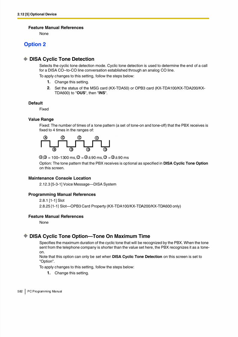
8/11/2019 TDA ProgrammingManual
http://slidepdf.com/reader/full/tda-programmingmanual 582/720
2.12 [5] Optional Device
582 PC Programming Manual
Feature Manual References
None
Option 2
DISA Cyclic Tone DetectionSelects the cyclic tone detection mode. Cyclic tone detection is used to determine the end of a callfor a DISA CO--to-CO line conversation established through an analog CO line.
To apply changes to this setting, follow the steps below:
1. Change this setting.
2. Set the status of the MSG card (KX-TDA50) or OPB3 card (KX-TDA100/KX-TDA200/KX-TDA600) to "OUS", then "INS".
Default
Fixed
Value Range
Fixed: The number of times of a tone pattern (a set of tone-on and tone-off) that the PBX receives isfixed to 4 times in the ranges of:
, = 100–1300 ms, = 90 ms, = 90 ms
Option: The tone pattern that the PBX receives is optional as specified in DISA Cyclic Tone Option on this screen.
Maintenance Console Location
2.12.3 [5-3-1] Voice Message—DISA System
Programming Manual References
2.8.1 [1-1] Slot
2.8.25 [1-1] Slot—OPB3 Card Property (KX-TDA100/KX-TDA200/KX-TDA600 only)
Feature Manual References
None
DISA Cyclic Tone Option—Tone On Maximum TimeSpecifies the maximum duration of the cyclic tone that will be recognized by the PBX. When the tonesent from the telephone company is shorter than the value set here, the PBX recognizes it as a tone-on.Note that this option can only be set when DISA Cyclic Tone Detection on this screen is set to"Option".
To apply changes to this setting, follow the steps below:
1. Change this setting.
A
B
C
D
C C
D D
A B C A D B
8/11/2019 TDA ProgrammingManual
http://slidepdf.com/reader/full/tda-programmingmanual 583/720
2.12 [5] Optional Device
PC Programming Manual 583
2. Set the status of the MSG card (KX-TDA50) or OPB3 card (KX-TDA100/KX-TDA200/KX-TDA600) card to "OUS", then "INS".
Default
600 ms
Value Range10 × n (n=11–400) ms
Maintenance Console Location
2.12.3 [5-3-1] Voice Message—DISA System
Programming Manual References
2.8.1 [1-1] Slot
2.8.25 [1-1] Slot—OPB3 Card Property (KX-TDA100/KX-TDA200/KX-TDA600 only)
Feature Manual References
None
DISA Cyclic Tone Option—Tone Off Maximum Time
Specifies the maximum time that the PBX waits for a cyclic tone to be sent from the telephonecompany before recognizing it as a tone-off. When no tone is detected within the time set here, thePBX recognizes it as a tone-off.Note that this option can only be set when DISA Cyclic Tone Detection on this screen is set to"Option".
To apply changes to this setting, follow the steps below:
1. Change this setting
2. Set the status of the MSG card (KX-TDA50) or OPB3 card (KX-TDA100/KX-TDA200/KX-TDA600) card to "OUS", then "INS".
Default
600 ms
Value Range
10 × n (n=11–400) ms
Maintenance Console Location
2.12.3 [5-3-1] Voice Message—DISA System
Programming Manual References
2.8.1 [1-1] Slot
2.8.25 [1-1] Slot—OPB3 Card Property (KX-TDA100/KX-TDA200/KX-TDA600 only)
Feature Manual References
None
8/11/2019 TDA ProgrammingManual
http://slidepdf.com/reader/full/tda-programmingmanual 584/720
2.12 [5] Optional Device
584 PC Programming Manual
DISA Cyclic Tone Option—Repeating Times of On/Off for Detection
Specifies the number of times the tone pattern (a set of tone-on and tone-off) must be received toestablish reception of the cyclic tone. This determines the end of call.Note that this option can only be set when DISA Cyclic Tone Detection on this screen is set to"Option".
Default3
Value Range
3–16
Maintenance Console Location
2.12.3 [5-3-1] Voice Message—DISA System
Programming Manual References
None
Feature Manual References
None
Timed Reminder Message - Day, Lunch, Break, Night
Specifies the prerecorded message to play when a Timed Reminder call is answered in each timemode.
Default
None
Value Range
For KX-TDA50:None, 1–32
For KX-TDA100/KX-TDA200/KX-TDA600:
None, 1–64
Maintenance Console Location
2.12.3 [5-3-1] Voice Message—DISA System
Programming Manual References
2.12.4 [5-3-2] Voice Message—DISA Message
Feature Manual References
1.17.4 Timed Reminder
8/11/2019 TDA ProgrammingManual
http://slidepdf.com/reader/full/tda-programmingmanual 585/720
2.12 [5] Optional Device
PC Programming Manual 585
Recording Mode
Specifies the sound quality of messages recorded on the ESVM card when using it as a MSG card.Increasing the recording quality reduces the total length of recording time available on the card.
To apply changes to this setting, follow the steps below:
1. Change this setting.
2. Set the status of the OPB3 card to "OUS", then "INS".
Default
High
Value Range
Low: About 120 minutes of messages can be recorded per card.Middle: About 60 minutes of messages can be recorded per card.High: About 40 minutes of messages can be recorded per card.
Maintenance Console Location
2.12.3 [5-3-1] Voice Message—DISA System
Programming Manual References
None
Feature Manual References
1.16.5 SVM (Simplified Voice Message)
2.12.4 [5-3-2] Voice Message—DISA Message
Outgoing messages (OGM) for DISA calls can be specified. A maximum of 32 (with the KX-TDA50)
or 64 (with the KX-TDA100/KX-TDA200/KX-TDA600) OGMs can be programmed.To view a list of all programmed extension numbers and types, click Extension List View (see 2.5.6Tool—Extension List View). To assign AA destinations easily, click Extension Number Setting (see 2.1.6 Extension Number Setting).
Floating Extension Number
Specifies the floating extension number of the OGM.
Default
For KX-TDA50:
OGM 01–32: 501–532
For KX-TDA100/KX-TDA200/KX-TDA600:OGM 01–64: 501–564
Value Range
Max. 5 digits (consisting of 0–9)
8/11/2019 TDA ProgrammingManual
http://slidepdf.com/reader/full/tda-programmingmanual 586/720
2.12 [5] Optional Device
586 PC Programming Manual
Maintenance Console Location
2.12.4 [5-3-2] Voice Message—DISA Message
Programming Manual References
None
Feature Manual References
1.4.7 DISA (Direct Inward System Access)
1.12.2 OGM (Outgoing Message)
Name
Specifies the name of the OGM.
Default
OGM 01–xx: DISA 01–DISA xx
Value RangeMax. 20 characters
Maintenance Console Location
2.12.4 [5-3-2] Voice Message—DISA Message
Programming Manual References
None
Feature Manual References
1.4.7 DISA (Direct Inward System Access)
1.12.2 OGM (Outgoing Message)
1 Digit AA Destination (Extension Number)—Dial 0–9
Specifies the destination for each DISA Automated Attendant (AA) number. After listening to an OGM,the caller can be directed to the destination by dialing a 1-digit DISA AA number.
Default
Not stored.
Value Range
Max. 5 digits (consisting of 0–9, *, and #)
Maintenance Console Location
2.12.4 [5-3-2] Voice Message—DISA Message
Programming Manual References
None
8/11/2019 TDA ProgrammingManual
http://slidepdf.com/reader/full/tda-programmingmanual 587/720
2.12 [5] Optional Device
PC Programming Manual 587
Feature Manual References
1.4.7 DISA (Direct Inward System Access)
1.12.2 OGM (Outgoing Message)
Busy / DND Message No.
Selects the OGM to be played for the caller when the destination party is busy or sets DND.
Default
None
Value Range
For KX-TDA50:
None, 1–32
For KX-TDA100/KX-TDA200/KX-TDA600:
None, 1–64
Maintenance Console Location
2.12.4 [5-3-2] Voice Message—DISA Message
Programming Manual References
2.12.3 [5-3-1] Voice Message—DISA System
Feature Manual References
1.4.7 DISA (Direct Inward System Access)
Fax Extension (KX-TDA50 only)
Specifies the extension number to which to transfer a call when the MSG card detects a fax signal.
Default
Not stored.
Value Range
Max. 4 digits (consisting of 0–9)
Maintenance Console Location
2.12.4 [5-3-2] Voice Message—DISA Message
Programming Manual References
None
Feature Manual References
1.1.6 Automatic Fax Transfer
1.4.7 DISA (Direct Inward System Access)
8/11/2019 TDA ProgrammingManual
http://slidepdf.com/reader/full/tda-programmingmanual 588/720
2.12 [5] Optional Device
588 PC Programming Manual
2.12.5 [5-3-3] Voice Message—SVM
Settings related to the SVM/ESVM cards can be specified, for use with the Simplified Voice Messagefeature.
SVM Card No. 1, 2—Slot No.Indicates the slot position (reference only).
Default
Current slot number
Value Range
Slot number
Maintenance Console Location
2.12.5 [5-3-3] Voice Message—SVM
Programming Manual References
None
Feature Manual References
1.16.5 SVM (Simplified Voice Message)
SVM Card No. 1, 2—Floating Extension Number
Specifies the floating extension number used to access the SVM/ESVM card.
DefaultCard No. 1: 591Card No. 2: 592
Value Range
Max. 5 digits (consisting of 0–9)
Maintenance Console Location
2.12.5 [5-3-3] Voice Message—SVM
Programming Manual References
None
Feature Manual References
1.16.5 SVM (Simplified Voice Message)
SVM Card No. 1, 2—Card Name
Specifies the name of the SVM/ESVM card, for programming reference.
8/11/2019 TDA ProgrammingManual
http://slidepdf.com/reader/full/tda-programmingmanual 589/720
2.12 [5] Optional Device
PC Programming Manual 589
Default
Card No. 1: Voice Msg 1Card No. 2: Voice Msg 2
Value Range
Max. 20 characters
Maintenance Console Location
2.12.5 [5-3-3] Voice Message—SVM
Programming Manual References
None
Feature Manual References
1.16.5 SVM (Simplified Voice Message)
Recording ModeSpecifies the sound quality of messages recorded on the SVM/ESVM card. Increasing the recordingquality reduces the total length of recording time available on the card.
Default
Middle
Value Range
Low: About 120 minutes of messages can be recorded per card.Middle: About 60 minutes of messages can be recorded per card.High: About 40 minutes (SVM)/20 minutes (ESVM) of messages can be recorded per card.
Maintenance Console Location
2.12.5 [5-3-3] Voice Message—SVM
Programming Manual References
2.11.9 [4-1-7] Wired Extension—Simplified Voice Message
2.11.16 [4-2-5] Portable Station—Simplified Voice Message
Feature Manual References
1.16.5 SVM (Simplified Voice Message)
Remote Access
Selects whether the Walking COS feature can be used while listening to a greeting message from theSVM feature. Using Walking COS, a user can access his or her message box remotely.
Default
Disable
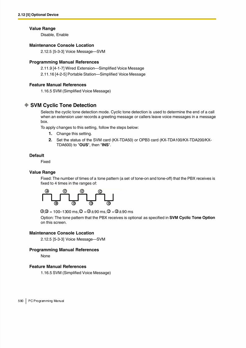
8/11/2019 TDA ProgrammingManual
http://slidepdf.com/reader/full/tda-programmingmanual 590/720
2.12 [5] Optional Device
590 PC Programming Manual
Value Range
Disable, Enable
Maintenance Console Location
2.12.5 [5-3-3] Voice Message—SVM
Programming Manual References
2.11.9 [4-1-7] Wired Extension—Simplified Voice Message
2.11.16 [4-2-5] Portable Station—Simplified Voice Message
Feature Manual References
1.16.5 SVM (Simplified Voice Message)
SVM Cyclic Tone Detection
Selects the cyclic tone detection mode. Cyclic tone detection is used to determine the end of a callwhen an extension user records a greeting message or callers leave voice messages in a message
box.To apply changes to this setting, follow the steps below:
1. Change this setting.
2. Set the status of the SVM card (KX-TDA50) or OPB3 card (KX-TDA100/KX-TDA200/KX-TDA600) to "OUS", then "INS".
Default
Fixed
Value Range
Fixed: The number of times of a tone pattern (a set of tone-on and tone-off) that the PBX receives is
fixed to 4 times in the ranges of:
, = 100–1300 ms, = 90 ms, = 90 ms
Option: The tone pattern that the PBX receives is optional as specified in SVM Cyclic Tone Option on this screen.
Maintenance Console Location
2.12.5 [5-3-3] Voice Message—SVM
Programming Manual References
None
Feature Manual References
1.16.5 SVM (Simplified Voice Message)
A
B
C
D
C C
D D
A B C A D B
8/11/2019 TDA ProgrammingManual
http://slidepdf.com/reader/full/tda-programmingmanual 591/720
2.12 [5] Optional Device
PC Programming Manual 591
SVM Cyclic Tone Option—Tone On Maximum Time
Specifies the maximum duration of the cyclic tone that will be recognized by the PBX. When the tonesent from the telephone company is shorter than the value set here, the PBX recognizes it as a tone-on.Note that this option can only be set when SVM Cyclic Tone Detection on this screen is set to"Option".
To apply changes to this setting, follow the steps below:1. Change this setting.
2. Set the status of the SVM card (KX-TDA50) or OPB3 card (KX-TDA100/KX-TDA200/KX-TDA600) to "OUS", then "INS".
Default
600 ms
Value Range
20 × n (n=6–200) ms
Maintenance Console Location2.12.5 [5-3-3] Voice Message—SVM
Programming Manual References
2.8.1 [1-1] Slot
Feature Manual References
1.16.5 SVM (Simplified Voice Message)
SVM Cyclic Tone Option—Tone Off Maximum Time
Specifies the maximum time that the PBX waits for a cyclic tone to be sent from the telephonecompany before recognizing it as a tone-off. When no tone is detected within the time set here, thePBX recognizes it as a tone-off.Note that this option can only be set when SVM Cyclic Tone Detection on this screen is set to"Option".
To apply changes to this setting, follow the steps below:
1. Change this setting.
2. Set the status of the SVM card (KX-TDA50) or OPB3 card (KX-TDA100/KX-TDA200/KX-TDA600) to "OUS", then "INS".
Default
600 ms
Value Range
20 × n (n=6–200) ms
Maintenance Console Location
2.12.5 [5-3-3] Voice Message—SVM
8/11/2019 TDA ProgrammingManual
http://slidepdf.com/reader/full/tda-programmingmanual 592/720
2.12 [5] Optional Device
592 PC Programming Manual
Programming Manual References
2.8.1 [1-1] Slot
Feature Manual References
1.16.5 SVM (Simplified Voice Message)
SVM Cyclic Tone Option—Repeating Times of On/Off for Detection
Specifies the number of times the tone pattern (a set of tone-on and tone-off) must be received toestablish reception of the cyclic tone. This determines the end of call.Note that this option can only be set when SVM Cyclic Tone Detection on this screen is set to"Option".
Default
3
Value Range
3–16
Maintenance Console Location
2.12.5 [5-3-3] Voice Message—SVM
Programming Manual References
None
Feature Manual References
1.16.5 SVM (Simplified Voice Message)
2.12.6 [5-4] External Relay
Settings related to external relays can be programmed.
External Relay No.
Indicates the number of the external relay (reference only).
Default
Current external relay number.
Value Range
For KX-TDA50:1–4
For KX-TDA100/KX-TDA200:
1–16
KX-TDA600:
1–64
8/11/2019 TDA ProgrammingManual
http://slidepdf.com/reader/full/tda-programmingmanual 593/720
2.12 [5] Optional Device
PC Programming Manual 593
Maintenance Console Location
2.12.6 [5-4] External Relay
Programming Manual References
None
Feature Manual References
1.5.8 External Relay
Physical Location—Shelf (KX-TDA600 only)
Indicates the shelf position (reference only).
Default
Current shelf number
Value Range
Shelf number
Maintenance Console Location
2.12.6 [5-4] External Relay
Programming Manual References
None
Feature Manual References
1.5.8 External Relay
Physical Location—Slot
Indicates the slot position (reference only).
Default
Current slot and sub-slot number.
Value Range
For KX-TDA50:
Slot number
For KX-TDA100/KX-TDA200/KX-TDA600:Slot and sub-slot number
Maintenance Console Location
2.12.6 [5-4] External Relay
Programming Manual References
None
8/11/2019 TDA ProgrammingManual
http://slidepdf.com/reader/full/tda-programmingmanual 594/720
2.12 [5] Optional Device
594 PC Programming Manual
Feature Manual References
1.5.8 External Relay
Physical Location—Port
Indicates the port number (reference only).
Default
Current port number.
Value Range
Port number
Maintenance Console Location
2.12.6 [5-4] External Relay
Programming Manual References
None
Feature Manual References
1.5.8 External Relay
Name
Specifies the relay name.
Default
Not stored.
Value Range
Max. 20 characters
Maintenance Console Location
2.12.6 [5-4] External Relay
Programming Manual References
None
Feature Manual References
1.5.8 External Relay
Relay Activate Time
Specifies the length of time that the relay stays on when activated.
Default
5 s
8/11/2019 TDA ProgrammingManual
http://slidepdf.com/reader/full/tda-programmingmanual 595/720
2.12 [5] Optional Device
PC Programming Manual 595
Value Range
1–7 s
Maintenance Console Location
2.12.6 [5-4] External Relay
Programming Manual References
None
Feature Manual References
1.5.8 External Relay
COS Number
Specifies the Class of Service (COS) number. COS programming determines the extensions that areable to activate relays.
Default1
Value Range
1–64
Maintenance Console Location
2.12.6 [5-4] External Relay
Programming Manual References
2.9.11 [2-7-1] Class of Service—COS Settings—Optional Device & Other Extensions—External
Relay Access
Feature Manual References
1.3.19 COS (Class of Service)
1.5.8 External Relay
1.9.14 Internal Call Block
2.12.7 [5-5] External Sensor
Settings related to external sensors can be programmed.
To assign destinations for sensor calls easily, click Destination Setting (see 2.1.6 ExtensionNumber Setting).
External Sensor No.
Indicates the number of the external sensor (reference only).
Default
Current external sensor number.
8/11/2019 TDA ProgrammingManual
http://slidepdf.com/reader/full/tda-programmingmanual 596/720
2.12 [5] Optional Device
596 PC Programming Manual
Value Range
For KX-TDA50:
1–4
For KX-TDA100/KX-TDA200:
1–16
KX-TDA600:1–64
Maintenance Console Location
2.12.7 [5-5] External Sensor
Programming Manual References
None
Feature Manual References
1.5.9 External Sensor
Physical Location—Shelf (KX-TDA600 only)
Indicates the shelf position (reference only).
Default
Current shelf number
Value Range
Shelf number
Maintenance Console Location2.12.7 [5-5] External Sensor
Programming Manual References
None
Feature Manual References
1.5.9 External Sensor
Physical Location—Slot
Indicates the slot position (reference only).
Default
Current slot and sub-slot number.
Value Range
For KX-TDA50:
Slot number
8/11/2019 TDA ProgrammingManual
http://slidepdf.com/reader/full/tda-programmingmanual 597/720
2.12 [5] Optional Device
PC Programming Manual 597
For KX-TDA100/KX-TDA200/KX-TDA600:
Slot and sub-slot number
Maintenance Console Location
2.12.7 [5-5] External Sensor
Programming Manual ReferencesNone
Feature Manual References
1.5.9 External Sensor
Physical Location—Port
Indicates the port number (reference only).
Default
Current port number.
Value Range
Port number
Maintenance Console Location
2.12.7 [5-5] External Sensor
Programming Manual References
None
Feature Manual References1.5.9 External Sensor
Name
Specifies the sensor name.
Default
Sensor
Value Range
Max. 20 characters
Maintenance Console Location
2.12.7 [5-5] External Sensor
Programming Manual References
None
8/11/2019 TDA ProgrammingManual
http://slidepdf.com/reader/full/tda-programmingmanual 598/720
2.12 [5] Optional Device
598 PC Programming Manual
Feature Manual References
1.5.9 External Sensor
Destination—Day, Lunch, Break, Night
Specifies the destination number of sensor calls for each port in each time mode.
Default
Not stored.
Value Range
Max. 32 digits (consisting of 0–9, *, #, [ ] [Secret], and P [Pause])
Maintenance Console Location
2.12.7 [5-5] External Sensor
Programming Manual References
None
Feature Manual References
1.5.9 External Sensor
Tenant No.
Specifies the tenant to which the sensor belongs, to determine the Time Table for the sensor. (Thetenant number corresponds to the Time Table number.)
Default
1
Value Range
For KX-TDA50/KX-TDA100/KX-TDA200:1-8
For KX-TDA600:
1-32
Maintenance Console Location
2.12.7 [5-5] External Sensor
Programming Manual References
2.9.5 [2-4] Week Table
Feature Manual References
1.5.9 External Sensor
1.17.3 Tenant Service
8/11/2019 TDA ProgrammingManual
http://slidepdf.com/reader/full/tda-programmingmanual 599/720
2.13 [6] Feature
PC Programming Manual 599
2.13 [6] Feature
2.13.1 [6-1] System Speed Dial
The System Speed Dialing Table is used to store frequently dialed numbers as well as callers whoshould be automatically routed to certain extensions when they call (Calling Line Identification [CLI]distribution). The System Speed Dialing Table is available for all extension users when making orreceiving a call.A maximum of 1000 System Speed Dialing numbers (e.g., telephone numbers, feature numbers) canbe programmed with other related parameters. 100 numbers are displayed at a time. To display othersets of numbers, click the applicable tab.
Memory
Selects the System Speed Dialing Table to be programmed. Whether a tenant uses the basic SystemSpeed Dialing Table or the additional table (with MEC [KX-TDA50/KX-TDA100/KX-TDA200] or EMEC[KX-TDA600] card) depends on the setting of System Speed Dial in 2.13.6 [6-6] Tenant.
Default
Basic Memory
Value Range
For KX-TDA50:
Basic Memory: the standard tableExpanded Memory: additional table (only available when an MEC card is installed to the PBX)
For KX-TDA100/KX-TDA200:
Basic Memory: the standard tableExpanded Memory for Tenant 1–8: additional tables (only available when an MEC card is installed tothe PBX)
For KX-TDA600:
Basic Memory: the standard tableExpanded Memory for Tenant 1–32: additional tables (only available when an EMEC card is installedto the PBX)
Maintenance Console Location
2.13.1 [6-1] System Speed Dial
Programming Manual References
2.13.6 [6-6] Tenant—System Speed Dial
Feature Manual References
1.16.4 Speed Dialing, System
1.17.3 Tenant Service
Name
Specifies a name for the System Speed Dialing number.
8/11/2019 TDA ProgrammingManual
http://slidepdf.com/reader/full/tda-programmingmanual 600/720
2.13 [6] Feature
600 PC Programming Manual
Default
Not stored.
Value Range
Max. 20 characters
Maintenance Console Location
2.13.1 [6-1] System Speed Dial
Programming Manual References
None
Feature Manual References
1.16.4 Speed Dialing, System
CO Line Access Number + Telephone Number
Specifies the telephone number (including the CO Line Access number) or feature number assignedto the System Speed Dialing number.
Default
Not stored.
Value Range
Max. 32 digits (consisting of 0–9, *, #, T [Transfer], [ ] [Secret], P [Pause], and F [Flash])
Maintenance Console Location
2.13.1 [6-1] System Speed Dial
Programming Manual References
None
Feature Manual References
1.16.4 Speed Dialing, System
CLI Destination
Specifies the CLI destination (extension) to which incoming calls from the programmed telephonenumber are routed. If a Caller ID Modification Table is being used, the modified number must match
the telephone number above (CO Line Access Number + Telephone Number) in order for the callto be routed correctly.
Default
Not stored.
Value Range
Max. 5 digits (consisting of 0–9)
8/11/2019 TDA ProgrammingManual
http://slidepdf.com/reader/full/tda-programmingmanual 601/720
2.13 [6] Feature
PC Programming Manual 601
Maintenance Console Location
2.13.1 [6-1] System Speed Dial
Programming Manual References
2.17.2 [10-2] DIL Table & Port Settings—CLI for DIL—CLI Ring for DIL—Day, Lunch, Break, Night
2.17.3 [10-3] DID Table (KX-TDA100/KX-TDA200/KX-TDA600 only)—CLI Ring for DID—Day, Lunch,
Break, Night
Feature Manual References
1.3.1 Caller ID
1.3.12 CLI (Calling Line Identification) Distribution
2.13.2 [6-2] Hotel
Various settings related to the hospitality features of the PBX can be set.
Main
Hotel Operator—Extension 1–4
Specifies the numbers of the extensions designated as hotel operators.
Default
For KX-TDA50/KX-TDA100/KX-TDA200:
Extension 1: 101
For KX-TDA600:Extension 1: 1001
Value Range
Max. 5 digits (consisting of 0–9)
Maintenance Console Location
2.13.2 [6-2] Hotel
Programming Manual References
None
Feature Manual References
1.8.4 HOSPITALITY FEATURES
1.15.3 Room Status Control
SMDR for External Hotel Application 1—Room Status Control
Selects whether check-in and check-out data is output on SMDR.
8/11/2019 TDA ProgrammingManual
http://slidepdf.com/reader/full/tda-programmingmanual 602/720
2.13 [6] Feature
602 PC Programming Manual
Default
No Print
Value Range
No Print, Print
Maintenance Console Location
2.13.2 [6-2] Hotel
Programming Manual References
2.18.1 [11-1] Main
Feature Manual References
1.15.3 Room Status Control
1.16.1 SMDR (Station Message Detail Recording)
SMDR for External Hotel Application 1—Timed Reminder (Wake-up Call)Selects whether Timed Reminder data is output on SMDR.
Default
No Print
Value Range
No Print, Print
Maintenance Console Location
2.13.2 [6-2] Hotel
Programming Manual References
2.18.1 [11-1] Main
Feature Manual References
1.16.1 SMDR (Station Message Detail Recording)
1.17.4 Timed Reminder
SMDR for External Hotel Application 2—Printing Message 1–8
Specifies the text of the message output on SMDR when this Printing Message is selected from an
extension.The "%" character can be used in a message, and requires a number to be entered in its place whenthe message is selected from an extension. This character can be used a maximum of seven timesin a Printing Message.
Default
Not stored.
8/11/2019 TDA ProgrammingManual
http://slidepdf.com/reader/full/tda-programmingmanual 603/720
2.13 [6] Feature
PC Programming Manual 603
Value Range
Max. 16 characters
Maintenance Console Location
2.13.2 [6-2] Hotel
Programming Manual References
2.18.1 [11-1] Main
Feature Manual References
1.13.11 Printing Message
1.16.1 SMDR (Station Message Detail Recording)
2.13.3 [6-3] Verification Code
A verification code is used to override the Toll Restriction (TRS) of the extension in use to make a
certain CO line call, or to identify the call for accounting and billing purposes.A maximum of 1000 verification codes can be programmed with other related parameters. 100 codesare displayed at a time. To display other sets of codes, click the applicable tab.
Verification Code
Specifies the verification code.
Default
Not stored.
Value Range
Max. 4 digits (consisting of 0–9, *, and #)
Maintenance Console Location
2.13.3 [6-3] Verification Code
Programming Manual References
None
Feature Manual References
1.19.1 Verification Code Entry
User Name
Specifies the user name assigned to the verification code.
Default
Not stored.
8/11/2019 TDA ProgrammingManual
http://slidepdf.com/reader/full/tda-programmingmanual 604/720
2.13 [6] Feature
604 PC Programming Manual
Value Range
Max. 20 characters
Maintenance Console Location
2.13.3 [6-3] Verification Code
Programming Manual References
None
Feature Manual References
1.19.1 Verification Code Entry
Verification Code PIN
Specifies the PIN to be entered when making a CO line call with the verification code.
Default
Not stored.
Value Range
Max. 10 digits (consisting of 0–9)
Maintenance Console Location
2.13.3 [6-3] Verification Code
Programming Manual References
None
Feature Manual References1.19.1 Verification Code Entry
WARNING
There is a risk that fraudulent telephone calls will be made if a third partydiscovers a personal identification number (PIN) (verification code PIN orextension PIN) of the PBX.The cost of such calls will be billed to the owner/renter of the PBX.
To protect the PBX from this kind of fraudulent use, we strongly recommend:
a) Keeping PINs secret.
b) Selecting complex, random PINs that cannot be easily guessed.
c) Changing PINs frequently.
COS Number
Specifies the COS that applies when making a CO line call with the verification code.
8/11/2019 TDA ProgrammingManual
http://slidepdf.com/reader/full/tda-programmingmanual 605/720
2.13 [6] Feature
PC Programming Manual 605
Default
1
Value Range
1–64
Maintenance Console Location
2.13.3 [6-3] Verification Code
Programming Manual References
2.9.11 [2-7-1] Class of Service—COS Settings
Feature Manual References
1.3.19 COS (Class of Service)
1.19.1 Verification Code Entry
Itemized Billing Code for ARSSpecifies the itemized billing code used by the ARS feature for identifying calls made with averification code for accounting and billing purposes.
Default
Not stored.
Value Range
Max. 10 digits (consisting of 0–9, *, and #)
Maintenance Console Location
2.13.3 [6-3] Verification Code
Programming Manual References
2.15.6 [8-5] Carrier
Feature Manual References
1.1.3 ARS (Automatic Route Selection)
2.13.4 [6-4] Second Dial Tone
A programmed Pause time can be inserted automatically between the Second Dial Tone Waitingcode and the following digits. When a programmed Second Dial Tone Waiting code is dialed afterseizing a CO line, a preprogrammed number of pauses are inserted after the code.A maximum of 100 Second Dial Tone Waiting codes can be programmed. 20 codes are displayed ata time. To display other sets of codes, click the applicable tab.
Second Dial Tone Waiting Code
Specifies the Second Dial Tone Waiting code.

8/11/2019 TDA ProgrammingManual
http://slidepdf.com/reader/full/tda-programmingmanual 606/720
2.13 [6] Feature
606 PC Programming Manual
Default
Not stored.
Value Range
Max. 4 digits (consisting of 0–9, *, and #)
Maintenance Console Location
2.13.4 [6-4] Second Dial Tone
Programming Manual References
None
Feature Manual References
1.13.4 Pause Insertion
Pause Repeating Counter
Specifies the number of pauses to be inserted when waiting for the second dial tone.
Default
1
Value Range
0–20
Maintenance Console Location
2.13.4 [6-4] Second Dial Tone
Programming Manual ReferencesNone
Feature Manual References
1.13.4 Pause Insertion
2.13.5 [6-5] Absent Message
When a display PT user calls an extension, a message is shown on the caller's telephone displaydescribing the reason for absence. A maximum of 8 Absent Messages can be programmed, and any
extension user can select one of them.
Absent Message
Specifies the message for display.
Default
1: Will Return Soon
2: Gone Home
8/11/2019 TDA ProgrammingManual
http://slidepdf.com/reader/full/tda-programmingmanual 607/720
2.13 [6] Feature
PC Programming Manual 607
3: At Ext %%%% (Extension Number)
4: Back at %%:%% (Hour:Minute)
5: Out until %%/%% (Month/Day)
6: In a Meeting
7 and 8: Not stored.
Value Range
Max. 16 characters
Maintenance Console Location
2.13.5 [6-5] Absent Message
Programming Manual References
None
Feature Manual References
1.1.1 Absent Message
2.13.6 [6-6] Tenant
A maximum of 8 (KX-TDA50/KX-TDA100/KX-TDA200)/32 (KX-TDA600) tenants can share the PBX.Each tenant is composed of specified extension user groups. The PBX offers each tenant its ownTime Table and system resources.To assign extensions as operators easily, click Extension Number Setting (see 2.1.6 Extension
Number Setting).
Music On Hold
Specifies the audio source to be used for Music on Hold.
Default
Same as System Setting
Value Range
For KX-TDA50:
Same as System Setting, BGM, Tone
For KX-TDA100/KX-TDA200/KX-TDA600:
Same as System Setting, BGM 1, BGM 2, Tone
Maintenance Console Location
2.13.6 [6-6] Tenant
Programming Manual References
2.9.3 [2-2] Operator & BGM
8/11/2019 TDA ProgrammingManual
http://slidepdf.com/reader/full/tda-programmingmanual 608/720
2.13 [6] Feature
608 PC Programming Manual
Feature Manual References
1.11.4 Music on Hold
1.17.3 Tenant Service
Operator (Extension Number)
Specifies the extension number or the floating extension number of an incoming call distribution groupto be designated as the tenant operator. When this parameter is left unspecified, the PBX operatorserves as the tenant operator.
Default
Not stored.
Value Range
Max. 5 digits (consisting of 0–9)
Maintenance Console Location
2.13.6 [6-6] Tenant
Programming Manual References
2.9.3 [2-2] Operator & BGM
Feature Manual References
1.12.5 Operator Features
1.17.3 Tenant Service
ARS Mode
Specifies the ARS mode used when making a CO line call.
Default
Same as System Setting
Value Range
Off: ARS is disabled.
On for Local Access Operation: ARS operates when an extension user makes a call using any IdleLine Access method.
On for Any CO Access Operation: ARS operates when an extension user makes a call using any COLine Access method.
Same as System Setting: The setting specified in ARS Mode in 2.15.1 [8-1] System Setting isapplied.
Maintenance Console Location
2.13.6 [6-6] Tenant
Programming Manual References
2.15.1 [8-1] System Setting
8/11/2019 TDA ProgrammingManual
http://slidepdf.com/reader/full/tda-programmingmanual 609/720
2.13 [6] Feature
PC Programming Manual 609
Feature Manual References
1.1.3 ARS (Automatic Route Selection)
1.17.3 Tenant Service
System Speed Dial
Specifies which system speed dialing table is used by the tenant. This setting is only available whenan MEC (KX-TDA50/KX-TDA100/KX-TDA200) or EMEC (KX-TDA600) card is installed.
Default
For KX-TDA50:
Basic Memory
For KX-TDA100/KX-TDA200/KX-TDA600:
Same as System Setting
Value Range
For KX-TDA50:
Basic Memory: PBX basic system speed dialing numbers are used.Expanded Memory: Expansion system speed dialing numbers are used.
For KX-TDA100/KX-TDA200/KX-TDA600:
Same as System Setting: PBX common system speed dialing numbers are used.Tenant Exclusive: Individual tenant system speed dialing numbers are used.
Maintenance Console Location
2.13.6 [6-6] Tenant
Programming Manual References
2.13.1 [6-1] System Speed Dial
Feature Manual References
1.16.4 Speed Dialing, System
1.17.3 Tenant Service
8/11/2019 TDA ProgrammingManual
http://slidepdf.com/reader/full/tda-programmingmanual 610/720
2.14 [7] TRS
610 PC Programming Manual
2.14 [7] TRS
2.14.1 [7-1] Denied Code
Toll Restriction (TRS) prohibits an extension from making certain CO line calls. Each time mode ofevery COS is assigned one of the seven TRS levels. TRS level 7 provides the maximum restriction(all CO line calls are prohibited) and level 1 provides the minimum (all CO line calls are allowed). TRSlevels 2–6 are used to restrict calls according to the codes programmed in the Denied Code Tables here and Exception Code Tables in 2.14.2 [7-2] Exception Code. If the leading digits of the dialednumber are not found in the applicable Denied Code Tables, the call is made.A maximum of 100 denied codes can be programmed for each level. 20 codes are displayed at a time.To display other sets of codes, click the applicable tab.
Denied Code Tables—Level 2–Level 6
Specifies the leading digits of toll restricted numbers for each level.
Default
Not stored.
Value Range
Max. 16 digits (consisting of 0–9, *, #, and X)
Maintenance Console Location
2.14.1 [7-1] Denied Code
Programming Manual References
2.9.11 [2-7-1] Class of Service—COS Settings—TRS—TRS Level—Day, Lunch, Break, Night
2.14.2 [7-2] Exception Code
Feature Manual References
1.17.6 TRS (Toll Restriction)
2.14.2 [7-2] Exception Code
Toll Restriction (TRS) prohibits an extension from making certain CO line calls. Each time mode ofevery COS is assigned one of the seven TRS levels. TRS level 7 provides the maximum restriction(all CO line calls are prohibited) and level 1 provides the minimum (all CO line calls are allowed). TRS
levels 2–6 are used to restrict calls according to the codes programmed in the Denied Code Tables in 2.14.1 [7-1] Denied Code and Exception Code Tables here. A call denied by the applicableDenied Code Tables is checked against the applicable Exception Code Tables, and if a match isfound, the call is made.A maximum of 100 exception codes can be programmed for each level. 20 codes are displayed at atime. To display other sets of codes, click the applicable tab.
8/11/2019 TDA ProgrammingManual
http://slidepdf.com/reader/full/tda-programmingmanual 611/720
2.14 [7] TRS
PC Programming Manual 611
Exception Code Tables—Level 2–Level 6
Specifies the leading digits of the numbers to be exempted from Toll Restriction for each level.
Default
Not stored.
Value Range
Max. 16 digits (consisting of 0–9, *, #, and X)
Maintenance Console Location
2.14.2 [7-2] Exception Code
Programming Manual References
2.9.11 [2-7-1] Class of Service—COS Settings—TRS—TRS Level—Day, Lunch, Break, Night
2.14.1 [7-1] Denied Code
Feature Manual References
1.17.6 TRS (Toll Restriction)
2.14.3 [7-3] Special Carrier
If the PBX has access to multiple telephone companies, a Special Carrier Access Code is requiredeach time a CO line call is made. By programming these Special Carrier Access Codes here, TollRestriction (TRS) can restrict or allow calls to be made by ignoring the codes and looking at thetelephone number only. If a Special Carrier Access Code is found in the dialed number, TRS will lookonly at the following digits.A maximum of 20 (with the KX-TDA50/KX-TDA100/KX-TDA200) or 100 (with the KX-TDA600)
Special Carrier Access Codes can be programmed. With the KX-TDA600, 20 codes are displayed ata time. To show other sets of codes, click the applicable tab.
Special Carrier Access Code
Specifies a Special Carrier Access Code. Special Carrier Access Codes and Host PBX Access codesshould be unique.
Default
Not stored.
Value Range
Max. 16 digits (consisting of 0–9, *, and #)
Maintenance Console Location
2.14.3 [7-3] Special Carrier
Programming Manual References
None
8/11/2019 TDA ProgrammingManual
http://slidepdf.com/reader/full/tda-programmingmanual 612/720
2.14 [7] TRS
612 PC Programming Manual
Feature Manual References
1.16.2 Special Carrier Access Code
1.17.6 TRS (Toll Restriction)
2.14.4 [7-4] Emergency Dial
Any extension user can dial the programmed emergency numbers at any time after seizing a CO line.The restrictions imposed on the extension, such as Toll Restriction (TRS), Account Code—Forcedmode, and Extension Dial Lock are disregarded.A maximum of 10 emergency numbers can be programmed.
Emergency Number
Specifies the numbers used for making emergency calls. It is not necessary to start the emergencynumber with a CO Line Access number.
Default
1: 911, 2–10: Not stored.
Value Range
Max. 32 digits (consisting of 0–9, *, #, T [Transfer], P [Pause], and F [Flash])
Maintenance Console Location
2.14.4 [7-4] Emergency Dial
Programming Manual References
None
Feature Manual References
1.5.2 Emergency Call
2.14.5 [7-5] Miscellaneous
Toll Restriction (TRS) prohibits an extension from making certain CO line calls. The following optionalsettings can be programmed to activate a TRS check, override TRS, or switch between TRSmethods.
TRS Override by System Speed DialingEnables an outgoing CO line call to override TRS when the call is made using System Speed Dialing.
Default
Enable
Value Range
Disable, Enable

8/11/2019 TDA ProgrammingManual
http://slidepdf.com/reader/full/tda-programmingmanual 613/720
2.14 [7] TRS
PC Programming Manual 613
Maintenance Console Location
2.14.5 [7-5] Miscellaneous
Programming Manual References
2.13.1 [6-1] System Speed Dial
Feature Manual References
1.17.6 TRS (Toll Restriction)
TRS Check for dial "* #"
Enables a TRS check for the user-dialed " " and "#". This is useful in preventing unauthorized callswhich could possibly be made through certain telephone company exchanges.
Default
No Check
Value RangeNo Check, Check
Maintenance Console Location
2.14.5 [7-5] Miscellaneous
Programming Manual References
None
Feature Manual References
1.17.6 TRS (Toll Restriction)
Mode when Dial Time-out before TRS Check
Selects whether a CO line is disconnected if the TRS check has not been completed when the COline Inter-digit timer expires.
Default
Disconnect
Value Range
Disconnect: The CO line is disconnected as soon as the timer expires.
Keep: The TRS check is performed when the timer expires.
Maintenance Console Location
2.14.5 [7-5] Miscellaneous
Programming Manual References
2.9.4 [2-3] Timers & Counters
8/11/2019 TDA ProgrammingManual
http://slidepdf.com/reader/full/tda-programmingmanual 614/720
2.14 [7] TRS
614 PC Programming Manual
Feature Manual References
1.17.6 TRS (Toll Restriction)
Dial Digits Limitation After Answering—Dial Digits
Specifies a limit to be placed on the number of digits which can be dialed after an extension user
receives a CO line call. If the number of dialed digits exceeds the programmed limit, the line will bedisconnected.
Default
None
Value Range
None, 1–7
Maintenance Console Location
2.14.5 [7-5] Miscellaneous
Programming Manual References
None
Feature Manual References
1.3.15 CO Line Call Limitation
1.17.6 TRS (Toll Restriction)
TRS Check after EFA
Enables TRS to check the digits dialed after External Feature Access (EFA) during a CO line call.
Default
Enable
Value Range
Disable, Enable
Maintenance Console Location
2.14.5 [7-5] Miscellaneous
Programming Manual References
None
Feature Manual References
1.5.1 EFA (External Feature Access)
1.17.6 TRS (Toll Restriction)
8/11/2019 TDA ProgrammingManual
http://slidepdf.com/reader/full/tda-programmingmanual 615/720
2.14 [7] TRS
PC Programming Manual 615
TRS Table Mode for Level N (N=2_6)
Selects the method of TRS to be used for restricting calls. The level of TRS is determined by thetelephone codes set in the Denied Code Tables and Exception Code Tables.
Default
Deny Table 2_N + Except Table N_6
Value Range
Deny Table 2_N + Except Table N_6: The Denied Code Tables for the higher levels are applied to alllevels below it, and the Exception Code Tables for the lower levels are applied to all levels above it.Deny Table N + Except Table N: Each level has its own separate set of denied codes and exceptioncodes, which are only applied to that level.
Maintenance Console Location
2.14.5 [7-5] Miscellaneous
Programming Manual References
None
Feature Manual References
1.17.6 TRS (Toll Restriction)
8/11/2019 TDA ProgrammingManual
http://slidepdf.com/reader/full/tda-programmingmanual 616/720
2.15 [8] ARS
616 PC Programming Manual
2.15 [8] ARS
2.15.1 [8-1] System Setting
Automatic Route Selection (ARS) automatically selects the appropriate carrier at the time a CO linecall is made, according to the programmed settings. The user-dialed number will be checked andmodified in order to connect it to the appropriate carrier.
ARS Mode
Selects the condition to determine when to operate ARS.
Default
Off
Value Range
Off: ARS is disabled.
On for Local Access Operation: ARS operates when an extension user makes a call using Idle LineAccess method.
On for Any CO Access Operation: ARS operates when an extension user makes a call using Idle LineAccess, CO Line Access, or S-CO Line Access method.
Maintenance Console Location
2.15.1 [8-1] System Setting
Programming Manual References
None
Feature Manual References
1.1.3 ARS (Automatic Route Selection)
1.3.14 CO Line Access
Mode When Any Carrier is not programmed for the Dial
Selects what happens when the dialed number is not found in Leading Number in 2.15.2 [8-2]
Leading Number.
Default
Local Access
Value Range
Disconnect: the line will be disconnected.
Local Access: the dialed number will be handled by Idle Line Access method.
Maintenance Console Location
2.15.1 [8-1] System Setting
8/11/2019 TDA ProgrammingManual
http://slidepdf.com/reader/full/tda-programmingmanual 617/720
2.15 [8] ARS
PC Programming Manual 617
Programming Manual References
None
Feature Manual References
1.1.3 ARS (Automatic Route Selection)
2.15.2 [8-2] Leading Number
Specifies the area codes and/or telephone numbers as leading numbers that will be routed by theARS feature. A maximum of 1000 different leading numbers can be programmed, and each leadingnumber can select a Routing Plan Table number, which determines the ARS procedure.The additional (remaining) number of digits can also be specified for each leading number. Theadditional (remaining) number of digits must be specified only when "#", for example, is needed afterthe dialed number. The "#" will be added after the programmed number of digits of the user-dialednumber (excluding the leading number).100 leading numbers are displayed at a time. To display other sets of leading numbers, click theapplicable tab.
Leading Number
Specifies the leading number.
Default
Not stored.
Value Range
Max. 16 digits (consisting of 0–9, *, #, and X)
Maintenance Console Location2.15.2 [8-2] Leading Number
Programming Manual References
None
Feature Manual References
1.1.3 ARS (Automatic Route Selection)
Additional Number of Digits
Specifies the additional (remaining) number of digits following each leading number.
Default
0
Value Range
0–15
8/11/2019 TDA ProgrammingManual
http://slidepdf.com/reader/full/tda-programmingmanual 618/720
2.15 [8] ARS
618 PC Programming Manual
Maintenance Console Location
2.15.2 [8-2] Leading Number
Programming Manual References
None
Feature Manual References
1.1.3 ARS (Automatic Route Selection)
Routing Plan Number
Specifies the Routing Plan Table number used for each leading number.
Default
1
Value Range
For KX-TDA50/KX-TDA100/KX-TDA200:1–16
For KX-TDA600:
1–48
Maintenance Console Location
2.15.2 [8-2] Leading Number
Programming Manual References
None
Feature Manual References
1.1.3 ARS (Automatic Route Selection)
2.15.3 [8-3] Routing Plan Time
The start and end times of a maximum of 4 different time blocks are shown for each day of the week.There are 16 (with the KX-TDA50/KX-TDA100/KX-TDA200) or 48 (with the KX-TDA600) RoutingPlan Tables, and each Routing Plan Table can have its own time blocks. Select the desired RoutingPlan Table number from the Routing Plan list.
• To adjust the currently displayed Routing Plan, click and drag the divisions between two time
periods.• To program the time blocks of the currently displayed Routing Plan, including adding or
deleting time blocks, click Time Setting.
2.15.4 [8-3] Routing Plan Time—Time Setting
The start times of a maximum of 4 different time blocks can be programmed for each day of the week,for the selected Routing Plan. Each time block automatically ends when the subsequent block begins.
8/11/2019 TDA ProgrammingManual
http://slidepdf.com/reader/full/tda-programmingmanual 619/720
2.15 [8] ARS
PC Programming Manual 619
Time-A–D—Setting
Enables the setting of the start time for each time block.
Default
Time-A–Time-C: Enable
Time-D: Disable
Value Range
Disable, Enable
Maintenance Console Location
2.15.4 [8-3] Routing Plan Time—Time Setting
Programming Manual References
None
Feature Manual References
1.1.3 ARS (Automatic Route Selection)
Time-A–D—Hour, Minute
Specifies the start time for each time block.
Default
Time-A: 8:00, Time-B: 17:00, Time-C: 21:00, Time-D: Not applicable.
Value Range
00:00–23:59
Maintenance Console Location
2.15.4 [8-3] Routing Plan Time—Time Setting
Programming Manual References
None
Feature Manual References
1.1.3 ARS (Automatic Route Selection)
2.15.5 [8-4] Routing Plan Priority
The carrier priority (1 through 6) in a Routing Plan Table can be programmed for each time zone ofeach day of the week. Select the desired Routing Plan Table number from the Routing Plan list.Select the desired day of the week by clicking the applicable tab.
Time-A–Time-D
Specifies the carrier to be given priority for each time zone.
8/11/2019 TDA ProgrammingManual
http://slidepdf.com/reader/full/tda-programmingmanual 620/720
2.15 [8] ARS
620 PC Programming Manual
Default
Priority 1: 1Priority 2–6: None
Value Range
For KX-TDA50/KX-TDA100/KX-TDA200:
None, 1–10
For KX-TDA600:
None, 1–48
Maintenance Console Location
2.15.5 [8-4] Routing Plan Priority
Programming Manual References
None
Feature Manual References1.1.3 ARS (Automatic Route Selection)
2.15.6 [8-5] Carrier
CarrierIt is possible to specify how user-dialed numbers are modified for connecting to the appropriatecarrier. A maximum of 10 (with the KX-TDA50/KX-TDA100/KX-TDA200) or 48 (with the KX-TDA600)different carriers can be programmed to be used with the ARS feature.
Carrier NameSpecifies the carrier name.
Default
Not stored.
Value Range
Max. 20 characters
Maintenance Console Location
2.15.6 [8-5] Carrier
Programming Manual References
None
Feature Manual References
1.1.3 ARS (Automatic Route Selection)
8/11/2019 TDA ProgrammingManual
http://slidepdf.com/reader/full/tda-programmingmanual 621/720
2.15 [8] ARS
PC Programming Manual 621
Removed Number of Digits
Specifies the number of leading digits to remove from the user-dialed number.
Default
0
Value Range
0–15
Maintenance Console Location
2.15.6 [8-5] Carrier
Programming Manual References
None
Feature Manual References
1.1.3 ARS (Automatic Route Selection)
Modify Command
Specifies the commands to modify the user-dialed number to access the carrier. For details of eachcommand, see the Feature Manual.
Default
CH
Value Range
Max. 16 characters (consisting of 0–9, *, #, C, P, A, G, I and H)
Maintenance Console Location
2.15.6 [8-5] Carrier
Programming Manual References
None
Feature Manual References
1.1.3 ARS (Automatic Route Selection)
Carrier Access CodeSpecifies the carrier access code. The carrier access code can be added to the user-dialed numberby specifying "C" in Modify Command on this screen.
Default
Not stored.

8/11/2019 TDA ProgrammingManual
http://slidepdf.com/reader/full/tda-programmingmanual 622/720
2.15 [8] ARS
622 PC Programming Manual
Value Range
Max. 32 digits (consisting of 0–9, *, #, and P [Pause])
Maintenance Console Location
2.15.6 [8-5] Carrier
Programming Manual References
None
Feature Manual References
1.1.3 ARS (Automatic Route Selection)
TRG 01–TRG 64 (KX-TDA50/KX-TDA100/KX-TDA200), or TRG 01–TRG 96(KX-TDA600)
Selects the trunk groups that connect to the carrier.
TRG 01–TRG 64 (KX-TDA50/KX-TDA100/KX-TDA200), or TRG 01–TRG 96(KX-TDA600)
Enables each trunk group for each carrier. If a cell is highlighted in blue, that trunk group is enabledfor use with that carrier.
Default
Trunk groups 01–04: ONAll other trunk groups: OFF
Value Range
OFF (white), ON (blue)
Maintenance Console Location
2.15.6 [8-5] Carrier
Programming Manual References
None
Feature Manual References
1.1.3 ARS (Automatic Route Selection)
Authorization Code for TenantSpecifies an Authorization code for each tenant. The Authorization codes can be added to the user-dialed number by specifying "A" command in Modify Command on the Carrier tab.
Authorization Code for Tenant—Tenant 1–Tenant 32
Specifies the Authorization code of each carrier for each tenant.
Note
For the KX-TDA50/KX-TDA100/KX-TDA200, only up to 8 tenants are available.
8/11/2019 TDA ProgrammingManual
http://slidepdf.com/reader/full/tda-programmingmanual 623/720
2.15 [8] ARS
PC Programming Manual 623
Default
Not stored.
Value Range
Max. 16 digits (consisting of 0–9, *, and #)
Maintenance Console Location
2.15.6 [8-5] Carrier
Programming Manual References
None
Feature Manual References
1.1.3 ARS (Automatic Route Selection)
1.17.3 Tenant Service
2.15.7 [8-6] Leading Number Exception
Specifies telephone numbers that will not be connected using the ARS feature. When the user-dialednumber includes a leading number exception, the PBX sends the number to a CO line by the Idle LineAccess method if ARS Mode in 2.15.1 [8-1] System Setting is "on".A maximum of 200 different leading number exceptions can be programmed. 40 leading numberexception entries are displayed on the screen at a time. To display other sets, click the applicable tab.
Leading Number Exception
Specifies the leading number exception.
Default
Not stored.
Value Range
Max. 16 digits (consisting of 0–9, *, #, and X)
Maintenance Console Location
2.15.7 [8-6] Leading Number Exception
Programming Manual References
None
Feature Manual References
1.1.3 ARS (Automatic Route Selection)
8/11/2019 TDA ProgrammingManual
http://slidepdf.com/reader/full/tda-programmingmanual 624/720
2.15 [8] ARS
624 PC Programming Manual
2.15.8 [8-7] Authorization Code for TRG
An Authorization code can be specified for each trunk group. The Authorization codes entered herecan be added to user-dialed numbers by adding "G" to the Modify Command specified on theCarrier tab of screen 2.15.6 [8-5] Carrier.8 trunk groups are displayed on the screen at a time. To display other groups, click the applicable tab.
Authorization Code for Trunk Group—TRG 01–TRG 64 (KX-TDA50/KX-TDA100/KX-TDA200), or TRG 01–TRG 96 (KX-TDA600)
Specifies the Authorization code of each carrier for each trunk group.
Default
Not stored.
Value Range
Max. 10 digits (consisting of 0–9, *, and #)
Maintenance Console Location
2.15.8 [8-7] Authorization Code for TRG
Programming Manual References
2.15.6 [8-5] Carrier—Carrier—Modify Command
Feature Manual References
1.1.3 ARS (Automatic Route Selection)
8/11/2019 TDA ProgrammingManual
http://slidepdf.com/reader/full/tda-programmingmanual 625/720
2.16 [9] Private Network
PC Programming Manual 625
2.16 [9] Private Network
2.16.1 [9-1] TIE Table
A TIE line is a privately leased communication line between two or more PBXs, which provides costeffective communications between company members at different locations.A maximum of 32 TIE Line Routing and Modification Tables can be programmed. It is necessary tomake unified tables with all PBXs at different locations in a TIE line network in order to identify theCO line route to be used when an extension makes or receives a TIE line call.There are two types of routing methods: the Extension Number Method, where all extensions in thenetwork are given a unique extension number; and the PBX Code Method, where each PBX is givena unique code, which is dialed before the extension number to call an extension at another PBX.Two priority sets (from a total of 8) are displayed at a time. To display other priority sets, click theapplicable tab.Using a private network, up to 8 PBXs can share one VPS (centralized VM) connected to anotherPBX. This VPS can provide voice mail for extensions attached to any of the PBXs in the network.
Own PBX Code
Specifies the PBX code of the local PBX, when using PBX Code Method numbering on a TIE linenetwork. If this cell is left empty, the Extension Number Method is used.
Default
Not stored.
Value Range
Max. 7 digits (consisting of 0–9)
Maintenance Console Location2.16.1 [9-1] TIE Table
Programming Manual References
None
Feature Manual References
1.13.13 PRIVATE NETWORK FEATURES
Priority 1–Priority 8
Leading Number
Specifies the leading number for other PBX extension numbers or the PBX code of others in the TIEline network.
Default
Not stored.
8/11/2019 TDA ProgrammingManual
http://slidepdf.com/reader/full/tda-programmingmanual 626/720
2.16 [9] Private Network
626 PC Programming Manual
Value Range
Max. 3 digits (consisting of 0–9, *, and #)
Maintenance Console Location
2.16.1 [9-1] TIE Table
Programming Manual References
None
Feature Manual References
1.13.13 PRIVATE NETWORK FEATURES
Removed Number of Digits
Specifies the number of leading digits of the dialed number to be removed for each priority.
Default
0
Value Range
0–15
Maintenance Console Location
2.16.1 [9-1] TIE Table
Programming Manual References
None
Feature Manual References1.13.13 PRIVATE NETWORK FEATURES
Added Number
Specifies the number to be added to the dialed number in place of the removed digits for each priority.
Default
Not stored.
Value Range
Max. 32 digits (consisting of 0–9, *, #, and P [Pause])
Maintenance Console Location
2.16.1 [9-1] TIE Table
Programming Manual References
None
8/11/2019 TDA ProgrammingManual
http://slidepdf.com/reader/full/tda-programmingmanual 627/720
2.16 [9] Private Network
PC Programming Manual 627
Feature Manual References
1.13.13 PRIVATE NETWORK FEATURES
Trunk Group
Specifies the trunk group to be used for TIE line calls for each priority.
Default
None
Value Range
For KX-TDA50/KX-TDA100/KX-TDA200:
None, 1–64
For KX-TDA600:
None, 1–96
Maintenance Console Location
2.16.1 [9-1] TIE Table
Programming Manual References
None
Feature Manual References
1.13.13 PRIVATE NETWORK FEATURES
Centralized VM
Leading Number
Specifies the leading number for other PBX extension numbers or the PBX code of other PBXs in theTIE line network.
Default
Not stored.
Value Range
Max. 3 digits (consisting of 0–9, *, and #)
Maintenance Console Location
2.16.1 [9-1] TIE Table
Programming Manual References
None
Feature Manual References
1.13.13 PRIVATE NETWORK FEATURES
8/11/2019 TDA ProgrammingManual
http://slidepdf.com/reader/full/tda-programmingmanual 628/720
2.16 [9] Private Network
628 PC Programming Manual
Enhanced QSIG Call Information (Optional SD Card Required)
Enables Network Message Waiting information to be sent from the PBX to which the VPS is attachedto extensions connected to other PBXs in the network.
Default
Enable
Value Range
Disable, Enable
Maintenance Console Location
2.16.1 [9-1] TIE Table
Programming Manual References
None
Feature Manual References
1.13.14 Private Network Features—Centralized Voice Mail
2.16.2 [9-2] Network Data Transmission
Settings related to the transmission of extension BLF (Busy Line Field) data or Message Waitingnotifications over a network of PBXs can be programmed.Extension BLF data is used to show the status of a monitored extension attached to another PBX ona Network DSS (NDSS) button. Network Message Waiting notifications are used for the CentralizedVM feature, and a VPS can send notifications to extensions connected to any PBX in the network.
Network Data Transmission for Centralized Operator Feature—Network PBXID
Specifies the Network ID of the PBX, for Network Direct Station Selection (NDSS). This parametermust be set in correspondence with the Network IDs assigned to other PBXs in the network.Network IDs 1-8 can only be assigned to one PBX each within a network. Assigning the sameNetwork ID to two PBXs will cause network data transmission problems.Changing this value in Interactive mode will automatically clear any NDSS Link Data.
Default
0
Value Range0: The PBX retransmits BLF data sent by other PBXs.1: The PBX receives BLF data sent by other PBXs.2–8: The PBX transmits BLF data over the network.
Maintenance Console Location
2.16.2 [9-2] Network Data Transmission

8/11/2019 TDA ProgrammingManual
http://slidepdf.com/reader/full/tda-programmingmanual 629/720
2.16 [9] Private Network
PC Programming Manual 629
Programming Manual References
None
Feature Manual References
1.13.15 Private Network Features—NDSS (Network Direct Station Selection)
Network Data Transmission for Centralized Operator Feature—DataTransmission VoIP->ISDN
Selects whether to re-send BLF data received from a VoIP port through any ISDN ports that are setto transmit BLF data.
Default
Disable
Value Range
Disable, Enable
Maintenance Console Location
2.16.2 [9-2] Network Data Transmission
Programming Manual References
2.8.14 [1-1] Slot—Port Property - PRI Port (KX-TDA100/KX-TDA200/KX-TDA600 only)—COSetting—Networking Data Transfer
Feature Manual References
1.13.15 Private Network Features—NDSS (Network Direct Station Selection)
Network Data Transmission for Centralized Operator Feature—DataTransmission ISDN->VoIP
Selects whether to re-send BLF data received from an ISDN port through any VoIP ports that are setto transmit BLF data.
Default
Disable
Value Range
Disable, Enable
Maintenance Console Location
2.16.2 [9-2] Network Data Transmission
Programming Manual References
2.16.3 [9-3] Network Operator (VoIP)—IP-GW Card Slot No. to notify BLF data to Network Operator
Feature Manual References
1.13.15 Private Network Features—NDSS (Network Direct Station Selection)
8/11/2019 TDA ProgrammingManual
http://slidepdf.com/reader/full/tda-programmingmanual 630/720
2.16 [9] Private Network
630 PC Programming Manual
Network Data Transmission for Centralized Operator Feature—DataTransmission Counter
Specifies the maximum number of "hops", or transmissions between two PBXs, before a packet ofBLF data is discarded.
Default
8
Value Range
1–63
Maintenance Console Location
2.16.2 [9-2] Network Data Transmission
Programming Manual References
None
Feature Manual References
1.13.15 Private Network Features—NDSS (Network Direct Station Selection)
Network Data Transmission for Centralized Operator Feature—DataBroadcasting Interval Timer
Specifies the frequency of BLF data transmission. The PBX will send data over the networkperiodically according to the interval specified here.
Default
3000 ms
Value Range
100 × n (n=0–30) ms
Maintenance Console Location
2.16.2 [9-2] Network Data Transmission
Programming Manual References
None
Feature Manual References
1.13.15 Private Network Features—NDSS (Network Direct Station Selection)
Network MSW Data Transmission for Centralized VM Feature—Data Re-transmission : Repeat Counter
Specifies the number of times re-transmission of network message waiting notifications is repeatedbefore being canceled.
8/11/2019 TDA ProgrammingManual
http://slidepdf.com/reader/full/tda-programmingmanual 631/720
2.16 [9] Private Network
PC Programming Manual 631
Default
3
Value Range
0–10
Maintenance Console Location
2.16.2 [9-2] Network Data Transmission
Programming Manual References
2.16.1 [9-1] TIE Table—Enhanced QSIG Call Information (Optional SD Card Required)
Feature Manual References
1.13.14 Private Network Features—Centralized Voice Mail
Network MSW Data Transmission for Centralized VM Feature—Data Re-
transmission : Repeat TimerSpecifies the length of time between repeated re-transmission of network message waitingnotifications.
Default
30 s
Value Range
10–240 s
Maintenance Console Location
2.16.2 [9-2] Network Data Transmission
Programming Manual References
2.16.1 [9-1] TIE Table—Enhanced QSIG Call Information (Optional SD Card Required)
Feature Manual References
1.13.14 Private Network Features—Centralized Voice Mail
2.16.3 [9-3] Network Operator (VoIP)
This screen allows network operators to be programmed. A network operator is an extension at aremote PBX that will monitor other PBX extensions using Network Direct Station Selection (NDSS).The settings on this screen should be programmed at the PBX that is to be monitored (Network DataTransmission for Centralized Operator Feature—Network PBX ID 2–8). Up to 8 network operatorscan be programmed.

8/11/2019 TDA ProgrammingManual
http://slidepdf.com/reader/full/tda-programmingmanual 632/720
2.16 [9] Private Network
632 PC Programming Manual
Network Operator Extension No.
Specifies the number of an extension at the monitor PBX (the PBX whose Network Data
Transmission for Centralized Operator Feature—Network PBX ID is set to 1 in 2.16.2 [9-2]Network Data Transmission). Any extension at the monitor PBX can be specified here.
Default
Not stored.
Value Range
Max. 16 digits (consisting of 0–9, *, and #)
Maintenance Console Location
2.16.3 [9-3] Network Operator (VoIP)
Programming Manual References
2.16.2 [9-2] Network Data Transmission—Network Data Transmission for Centralized OperatorFeature—Network PBX ID
Feature Manual References
1.13.15 Private Network Features—NDSS (Network Direct Station Selection)
IP-GW Card Slot No. to notify BLF data to Network Operator
Specifies the slot number (with the KX-TDA600, shelf and slot number) of the card used to sendextension status data. This setting is only required when using VoIP to transmit data.
Default
Undefined
Value Range
For KX-TDA50:Undefined, 5–7
For KX-TDA100/KX-TDA200:
Undefined, 1–11
For KX-TDA600:
Undefined, 1-1–4-11
Maintenance Console Location
2.16.3 [9-3] Network Operator (VoIP)
Programming Manual References
None
Feature Manual References
1.13.15 Private Network Features—NDSS (Network Direct Station Selection)
8/11/2019 TDA ProgrammingManual
http://slidepdf.com/reader/full/tda-programmingmanual 633/720
2.16 [9] Private Network
PC Programming Manual 633
2.16.4 [9-4] NDSS Key Table
Extensions at up to 7 other PBXs that will be monitored using Network Direct Station Selection(NDSS) can be registered. A maximum of 250 extensions can be registered. To create an NDSSbutton to monitor an extension, the extension must be registered here first.To clear NDSS link data, click the NDSS Clear button.
Note that the parameters on this screen can only be set when the Network Data Transmission forCentralized Operator Feature—Network PBX ID is set to 1 in the 2.16.2 [9-2] Network Data
Transmission screen.
Network Extension No.
Specifies the number of the remote extension (attached to another PBX) that will be monitored. Thenumber input here can use either Extension Number Method or PBX Code Method.
Default
Not stored.
Value Range
Max. 16 digits (consisting of 0–9, *, and #)
Maintenance Console Location
2.16.4 [9-4] NDSS Key Table
Programming Manual References
None
Feature Manual References
1.13.15 Private Network Features—NDSS (Network Direct Station Selection)
1.13.13 PRIVATE NETWORK FEATURES
Network Extension Name for Programming Reference
Specifies the name of the network extension. This name is only shown here, not on the displays ofextensions.
Default
Not stored.
Value Range
Max. 20 characters
Maintenance Console Location
2.16.4 [9-4] NDSS Key Table
Programming Manual References
None
8/11/2019 TDA ProgrammingManual
http://slidepdf.com/reader/full/tda-programmingmanual 634/720
2.16 [9] Private Network
634 PC Programming Manual
Feature Manual References
1.13.15 Private Network Features—NDSS (Network Direct Station Selection)
Network PBX ID of Network Extension to be monitored
Indicates the Network Data Transmission for Centralized Operator Feature—Network PBX ID of the
PBX that the extension is connected to (reference only).
Default
Not stored.
Value Range
None, 1–8
Maintenance Console Location
2.16.4 [9-4] NDSS Key Table
Programming Manual References2.16.2 [9-2] Network Data Transmission—Network Data Transmission for Centralized OperatorFeature—Network PBX ID
Feature Manual References
1.13.15 Private Network Features—NDSS (Network Direct Station Selection)
8/11/2019 TDA ProgrammingManual
http://slidepdf.com/reader/full/tda-programmingmanual 635/720
2.17 [10] CO & Incoming Call
PC Programming Manual 635
2.17 [10] CO & Incoming Call
2.17.1 [10-1] CO Line Settings
CO lines can be assigned a name, and grouped into a maximum of 64 (with the KX-TDA50/KX-TDA100/KX-TDA200) or 96 (with the KX-TDA600) trunk groups.For KX-TDA600, all supported cards are displayed in the Select Shelf & Slot list. Select the shelfand slot and card type to program, or select "All" to display all matching cards.
Physical—Shelf (KX-TDA600 only)
Indicates the shelf position of each CO line card (reference only).
Default
Current shelf position
Value RangeShelf number
Maintenance Console Location
2.17.1 [10-1] CO Line Settings
Programming Manual References
None
Feature Manual References
None
Physical—Slot
Indicates the slot position of each CO line card (reference only).
Default
Current slot number
Value Range
Slot number
Maintenance Console Location2.17.1 [10-1] CO Line Settings
Programming Manual References
None
Feature Manual References
None
8/11/2019 TDA ProgrammingManual
http://slidepdf.com/reader/full/tda-programmingmanual 636/720
2.17 [10] CO & Incoming Call
636 PC Programming Manual
Physical—Port
Indicates the port number (reference only).
Default
Current port number
Value Range
Port number
Maintenance Console Location
2.17.1 [10-1] CO Line Settings
Programming Manual References
None
Feature Manual References
None
CO Name
Specifies the CO line name which is shown on the extension's display when receiving a call from theCO line.
Default
Not stored.
Value Range
Max. 20 characters
Maintenance Console Location
2.17.1 [10-1] CO Line Settings
Programming Manual References
None
Feature Manual References
1.4.8 Display Information
Trunk Group NumberSpecifies the trunk group number to which the CO line belongs.
Default
1
8/11/2019 TDA ProgrammingManual
http://slidepdf.com/reader/full/tda-programmingmanual 637/720
2.17 [10] CO & Incoming Call
PC Programming Manual 637
Value Range
KX-TDA50/KX-TDA100/KX-TDA200:
1–64
KX-TDA600:
1–96
Maintenance Console Location
2.17.1 [10-1] CO Line Settings
Programming Manual References
None
Feature Manual References
1.7.1 GROUP FEATURES
2.17.2 [10-2] DIL Table & Port SettingsDirect In Line (DIL) or Direct Inward Dialing (DID) can be selected for each CO line as the method ofdistributing incoming CO line calls to certain destinations. For each CO line to which DIL distributionis set, different destinations can be programmed depending on the time mode (day/lunch/break/ night). If desired, Calling Line Identification (CLI) distribution can be used in conjunction with DILdistribution.For KX-TDA600, all supported cards are displayed in the Select Shelf & Slot list with their shelf andslot numbers. Select the card to program, or select "All" to display all matching cards.DID distribution is only available for the KX-TDA100, KX-TDA200 and KX-TDA600.
DIL
For each CO line to which DIL distribution is set, different DIL destinations can be programmeddepending on the time mode (day/lunch/break/night). Generally, DIL distribution is used for CO linecalls from analog CO lines. Tenant number and VM trunk group number can also be programmed foreach CO line.To assign DIL destination numbers, enter directly or click Destination Setting (see 2.1.6 Extension
Number Setting).
Shelf (KX-TDA600 only)
Indicates the shelf position (reference only).
Default
Current shelf number
Value Range
Shelf number
Maintenance Console Location
2.17.2 [10-2] DIL Table & Port Settings
8/11/2019 TDA ProgrammingManual
http://slidepdf.com/reader/full/tda-programmingmanual 638/720
2.17 [10] CO & Incoming Call
638 PC Programming Manual
Programming Manual References
None
Feature Manual References
None
Slot
Indicates the slot position of each CO line card (reference only).
Default
Current slot number
Value Range
Slot number
Maintenance Console Location
2.17.2 [10-2] DIL Table & Port Settings
Programming Manual References
None
Feature Manual References
None
Port
Indicates the port number (reference only).
Default
Current port number
Value Range
Port number
Maintenance Console Location
2.17.2 [10-2] DIL Table & Port Settings
Programming Manual References
None
Feature Manual References
None
Card Type
Indicates the CO line card type (reference only).
8/11/2019 TDA ProgrammingManual
http://slidepdf.com/reader/full/tda-programmingmanual 639/720
2.17 [10] CO & Incoming Call
PC Programming Manual 639
Default
Current card type
Value Range
Card type
Maintenance Console Location
2.17.2 [10-2] DIL Table & Port Settings
Programming Manual References
None
Feature Manual References
1.9.10 INCOMING CALL FEATURES
Trunk Property
Indicates the networking type of each CO line (reference only).
Default
Current networking type
Value Range
Public, Private(TIE), VPN
Maintenance Console Location
2.17.2 [10-2] DIL Table & Port Settings
Programming Manual ReferencesNone
Feature Manual References
1.9.10 INCOMING CALL FEATURES
1.13.13 PRIVATE NETWORK FEATURES
Distribution Method (KX-TDA100/KX-TDA200/KX-TDA600 only)
Selects the distribution method for incoming CO line calls. The value range of this setting dependson the card type and Trunk Property assigned for each CO line.
Default
DIL
Value Range
DIL: Distribution depends on the CO line through which the calls arriveDID: Distribution depends on the DID number of the calls
8/11/2019 TDA ProgrammingManual
http://slidepdf.com/reader/full/tda-programmingmanual 640/720
2.17 [10] CO & Incoming Call
640 PC Programming Manual
Maintenance Console Location
2.17.2 [10-2] DIL Table & Port Settings
Programming Manual References
None
Feature Manual References
1.9.10 INCOMING CALL FEATURES
DIL Destination—Day, Lunch, Break, Night
Specifies the DIL destination in each time mode.
Default
Not stored.
Value Range
Max. 5 digits (consisting of 0–9)
Maintenance Console Location
2.17.2 [10-2] DIL Table & Port Settings
Programming Manual References
2.9.8 [2-6-1] Numbering Plan—Main
Feature Manual References
1.4.6 DIL (Direct In Line)
1.13.13 PRIVATE NETWORK FEATURES
Tenant Number
Specifies the tenant number, to determine the Time Table by which calls are distributed dependingon the time of day.
Default
1
Value Range
For KX-TDA50/KX-TDA100/KX-TDA200:
1-8
For KX-TDA600:1-32
Maintenance Console Location
2.17.2 [10-2] DIL Table & Port Settings
8/11/2019 TDA ProgrammingManual
http://slidepdf.com/reader/full/tda-programmingmanual 641/720
2.17 [10] CO & Incoming Call
PC Programming Manual 641
Programming Manual References
2.9.5 [2-4] Week Table
Feature Manual References
1.4.6 DIL (Direct In Line)
1.17.3 Tenant Service
1.17.5 Time Service
VM Trunk Group No.
Specifies the number of the VM trunk group sent to the VPS when the DIL destination is the floatingextension number of a VM (DPT) Group.The VM trunk group number is used to allow the VPS to send the applicable greeting message to thecaller.
Default
1
Value Range
1–48
Maintenance Console Location
2.17.2 [10-2] DIL Table & Port Settings
Programming Manual References
None
Feature Manual References
1.4.6 DIL (Direct In Line)1.19.4 Voice Mail DPT (Digital) Integration
CLI for DILWhen CLI distribution is enabled for a CO line to which DIL distribution is set, incoming CO line callswill be distributed to the CLI destinations (instead of the DIL destinations) if the caller's identificationnumber is found in the System Speed Dialing Table.CLI distribution can be enabled or disabled for each time mode (day/lunch/break/night) on a CO linebasis.
Shelf (KX-TDA600 only)
Indicates the shelf position (reference only).
Default
Current shelf number
Value Range
Shelf number
8/11/2019 TDA ProgrammingManual
http://slidepdf.com/reader/full/tda-programmingmanual 642/720
2.17 [10] CO & Incoming Call
642 PC Programming Manual
Maintenance Console Location
2.17.2 [10-2] DIL Table & Port Settings
Programming Manual References
None
Feature Manual References
None
Slot
Indicates the slot position of each CO line card (reference only).
Default
Current slot number
Value Range
Slot number
Maintenance Console Location
2.17.2 [10-2] DIL Table & Port Settings
Programming Manual References
None
Feature Manual References
None
Port
Indicates the port number (reference only).
Default
Current port number
Value Range
Port number
Maintenance Console Location
2.17.2 [10-2] DIL Table & Port Settings
Programming Manual References
None
Feature Manual References
None
8/11/2019 TDA ProgrammingManual
http://slidepdf.com/reader/full/tda-programmingmanual 643/720
2.17 [10] CO & Incoming Call
PC Programming Manual 643
Card Type
Indicates the CO line card type (reference only).
Default
Current card type
Value Range
Card type
Maintenance Console Location
2.17.2 [10-2] DIL Table & Port Settings
Programming Manual References
None
Feature Manual References
1.9.10 INCOMING CALL FEATURES
Trunk Property
Indicates the networking type of each CO line (reference only).
Default
Current networking type
Value Range
Public, Private(TIE), VPN
Maintenance Console Location
2.17.2 [10-2] DIL Table & Port Settings
Programming Manual References
None
Feature Manual References
1.9.10 INCOMING CALL FEATURES
1.13.13 PRIVATE NETWORK FEATURES
Distribution Method (KX-TDA100/KX-TDA200/KX-TDA600 only)Selects the distribution method for incoming CO line calls. The value range of this setting dependson the card type and Trunk Property assigned for each CO line.
Default
DIL

8/11/2019 TDA ProgrammingManual
http://slidepdf.com/reader/full/tda-programmingmanual 644/720
2.17 [10] CO & Incoming Call
644 PC Programming Manual
Value Range
DIL: Distribution depends on the CO line through which the calls arriveDID: Distribution depends on the DID number of the calls
Maintenance Console Location
2.17.2 [10-2] DIL Table & Port Settings
Programming Manual References
None
Feature Manual References
1.9.10 INCOMING CALL FEATURES
CLI Ring for DIL—Day, Lunch, Break, Night
Enables CLI distribution in each time mode.
DefaultDisable
Value Range
Disable, Enable
Maintenance Console Location
2.17.2 [10-2] DIL Table & Port Settings
Programming Manual References
None
Feature Manual References
1.3.12 CLI (Calling Line Identification) Distribution
1.4.6 DIL (Direct In Line)
DID/TIEFor each CO line to which DID distribution is set, or for each CO line whose Trunk Property on thisscreen is Private (TIE), modification parameters for DID number and TIE line call numbers can beprogrammed.
Shelf (KX-TDA600 only)Indicates the shelf position (reference only).
Default
Current shelf number
Value Range
Shelf number
8/11/2019 TDA ProgrammingManual
http://slidepdf.com/reader/full/tda-programmingmanual 645/720
2.17 [10] CO & Incoming Call
PC Programming Manual 645
Maintenance Console Location
2.17.2 [10-2] DIL Table & Port Settings
Programming Manual References
None
Feature Manual References
None
Slot
Indicates the slot position of each CO line card (reference only).
Default
Current slot number
Value Range
Slot number
Maintenance Console Location
2.17.2 [10-2] DIL Table & Port Settings
Programming Manual References
None
Feature Manual References
None
Port
Indicates the port number (reference only).
Default
Current port number
Value Range
Port number
Maintenance Console Location
2.17.2 [10-2] DIL Table & Port Settings
Programming Manual References
None
Feature Manual References
None
8/11/2019 TDA ProgrammingManual
http://slidepdf.com/reader/full/tda-programmingmanual 646/720
2.17 [10] CO & Incoming Call
646 PC Programming Manual
Card Type
Indicates the CO line card type (reference only).
Default
Current card type
Value Range
Card type
Maintenance Console Location
2.17.2 [10-2] DIL Table & Port Settings
Programming Manual References
None
Feature Manual References
1.9.10 INCOMING CALL FEATURES
Trunk Property
Indicates the networking type of each CO line (reference only).
Default
Current networking type
Value Range
Public, Private(TIE), VPN
Maintenance Console Location
2.17.2 [10-2] DIL Table & Port Settings
Programming Manual References
None
Feature Manual References
1.9.10 INCOMING CALL FEATURES
1.13.13 PRIVATE NETWORK FEATURES
Distribution Method (KX-TDA100/KX-TDA200/KX-TDA600 only)Selects the distribution method for incoming CO line calls. The value range of this setting dependson the card type and Trunk Property assigned for each CO line.
Default
DIL
8/11/2019 TDA ProgrammingManual
http://slidepdf.com/reader/full/tda-programmingmanual 647/720
2.17 [10] CO & Incoming Call
PC Programming Manual 647
Value Range
DIL: Distribution depends on the CO line through which the calls arriveDID: Distribution depends on the DID number of the calls
Maintenance Console Location
2.17.2 [10-2] DIL Table & Port Settings
Programming Manual References
None
Feature Manual References
1.4.5 DID (Direct Inward Dialing)
1.9.10 INCOMING CALL FEATURES
DID/TIE—Remove Digit
Specifies the number of leading digits to be removed from the incoming called number for DID
distribution (KX-TDA100/KX-TDA200/KX-TDA600) or for TIE line service.With the KX-TDA50, this parameter is shown as TIE—Remove Digit.
Default
0
Value Range
0–15
Maintenance Console Location
2.17.2 [10-2] DIL Table & Port Settings
Programming Manual References
None
Feature Manual References
1.4.5 DID (Direct Inward Dialing)
1.13.13 PRIVATE NETWORK FEATURES
DID/TIE—Additional Dial
Specifies the number to be added to the incoming called number in the place of the removed digits
for DID distribution or for TIE line service.With the KX-TDA50, this parameter is shown as TIE—Remove Digit.
Default
Not stored.
Value Range
Max. 8 digits (consisting of 0–9, *, and #)
8/11/2019 TDA ProgrammingManual
http://slidepdf.com/reader/full/tda-programmingmanual 648/720
2.17 [10] CO & Incoming Call
648 PC Programming Manual
Maintenance Console Location
2.17.2 [10-2] DIL Table & Port Settings
Programming Manual References
None
Feature Manual References
1.4.5 DID (Direct Inward Dialing)
1.13.13 PRIVATE NETWORK FEATURES
2.17.3 [10-3] DID Table (KX-TDA100/KX-TDA200/KX-TDA600 only)
Incoming CO line calls with DID numbers can be distributed to specific destinations. Each DIDnumber has a destination programmed for each time mode (day/lunch/break/night).When CLI distribution is enabled for a DID number, incoming CO line calls with that DID number willbe distributed to the CLI destinations (instead of the DID destinations) if the caller's identification
number is found in the System Speed Dialing Table, which is used as the Caller ID Table. CLIdistribution can be enabled or disabled for each time mode (day/lunch/break/night) on a DID numberbasis.A maximum of 1000 DID numbers can be programmed with other related parameters. 100 numbersare displayed at a time. To display other sets of numbers, click the applicable tab.To assign DID destination numbers, enter directly or click Destination Setting (see 2.1.6 Extension
Number Setting). It is possible to program DID numbers and DID destinations in each time mode(day/lunch/break/night) for a set of locations in series at once by clicking Automatic Registration, orto program DID names for a set of locations in series at once by clicking Name Generate.
DID Number
Specifies the DID number.
Default
Not stored.
Value Range
Max. 32 digits (consisting of 0–9, *, and #)
Maintenance Console Location
2.17.3 [10-3] DID Table (KX-TDA100/KX-TDA200/KX-TDA600 only)
Programming Manual References
2.17.4 [10-3] DID Table—Automatic Registration (KX-TDA100/KX-TDA200/KX-TDA600 only)
Feature Manual References
1.4.5 DID (Direct Inward Dialing)
8/11/2019 TDA ProgrammingManual
http://slidepdf.com/reader/full/tda-programmingmanual 649/720
2.17 [10] CO & Incoming Call
PC Programming Manual 649
DID Name
Specifies the name for the DID number which is shown on the extension's display when receiving acall with the DID number. The name of the DID number can be printed out on SMDR.
Default
Not stored.
Value Range
Max. 20 characters
Maintenance Console Location
2.17.3 [10-3] DID Table (KX-TDA100/KX-TDA200/KX-TDA600 only)
Programming Manual References
2.17.5 [10-3] DID Table—Name Generate (KX-TDA100/KX-TDA200/KX-TDA600 only)
2.18.1 [11-1] Main—SMDR Options—SMDR Options—DID Number & Name (KX-TDA100/KX-TDA200/KX-TDA600)
Feature Manual References
1.4.5 DID (Direct Inward Dialing)
DID Destination—Day, Lunch, Break, Night
Specifies the DID destination in each time mode.
Default
Not stored.
Value RangeMax. 5 digits (consisting of 0–9)
Maintenance Console Location
2.17.3 [10-3] DID Table (KX-TDA100/KX-TDA200/KX-TDA600 only)
Programming Manual References
2.9.8 [2-6-1] Numbering Plan—Main
2.17.4 [10-3] DID Table—Automatic Registration (KX-TDA100/KX-TDA200/KX-TDA600 only)
Feature Manual References
1.4.5 DID (Direct Inward Dialing)
1.13.13 PRIVATE NETWORK FEATURES
Tenant Number
Specifies the tenant number, to determine the Time Table by which calls are distributed dependingon the time of day.
8/11/2019 TDA ProgrammingManual
http://slidepdf.com/reader/full/tda-programmingmanual 650/720
2.17 [10] CO & Incoming Call
650 PC Programming Manual
Default
1
Value Range
For KX-TDA50/KX-TDA100/KX-TDA200:1-8
For KX-TDA600:
1-32
Maintenance Console Location
2.17.3 [10-3] DID Table (KX-TDA100/KX-TDA200/KX-TDA600 only)
Programming Manual References
2.9.5 [2-4] Week Table
Feature Manual References
1.4.5 DID (Direct Inward Dialing)
VM Trunk Group No.
Specifies the number of the VM trunk group sent to the VPS when the DID destination is the floatingextension number of a VM (DPT) Group.The VM trunk group number is used to allow the VPS to send the applicable greeting message to thecaller.
Default
1
Value Range1–48
Maintenance Console Location
2.17.3 [10-3] DID Table (KX-TDA100/KX-TDA200/KX-TDA600 only)
Programming Manual References
None
Feature Manual References
1.4.5 DID (Direct Inward Dialing)
1.19.4 Voice Mail DPT (Digital) Integration
CLI Ring for DID—Day, Lunch, Break, Night
Enables CLI distribution in each time mode.
Default
Disable
8/11/2019 TDA ProgrammingManual
http://slidepdf.com/reader/full/tda-programmingmanual 651/720
2.17 [10] CO & Incoming Call
PC Programming Manual 651
Value Range
Disable, Enable
Maintenance Console Location
2.17.3 [10-3] DID Table (KX-TDA100/KX-TDA200/KX-TDA600 only)
Programming Manual References
2.13.1 [6-1] System Speed Dial
Feature Manual References
1.3.12 CLI (Calling Line Identification) Distribution
1.4.5 DID (Direct Inward Dialing)
2.17.4 [10-3] DID Table—Automatic Registration (KX-TDA100/KX-TDA200/KX-TDA600 only)
Automatic Registration allows DID numbers and DID destinations in each time mode (day/lunch/ break/night) to be programmed at once for a set of locations in series.
Beginning Entry Location
Specifies the number of the first location to be programmed.
Default
1
Value Range
1–1000
Maintenance Console Location
2.17.4 [10-3] DID Table—Automatic Registration (KX-TDA100/KX-TDA200/KX-TDA600 only)
Programming Manual References
2.17.3 [10-3] DID Table (KX-TDA100/KX-TDA200/KX-TDA600 only)
Feature Manual References
1.4.5 DID (Direct Inward Dialing)
Generate DID Number (From)
Specifies the DID number of the first location to be programmed. DID numbers for subsequentlocations will be generated automatically, by adding one to the value of the previous location.
Default
Not stored.
8/11/2019 TDA ProgrammingManual
http://slidepdf.com/reader/full/tda-programmingmanual 652/720
2.17 [10] CO & Incoming Call
652 PC Programming Manual
Value Range
Max. 32 digits (consisting of 0–9)
Maintenance Console Location
2.17.4 [10-3] DID Table—Automatic Registration (KX-TDA100/KX-TDA200/KX-TDA600 only)
Programming Manual References
2.17.3 [10-3] DID Table (KX-TDA100/KX-TDA200/KX-TDA600 only)
Feature Manual References
1.4.5 DID (Direct Inward Dialing)
Number of Registration
Specifies the number of locations to be programmed.
Default
100
Value Range
1–1000
Maintenance Console Location
2.17.4 [10-3] DID Table—Automatic Registration (KX-TDA100/KX-TDA200/KX-TDA600 only)
Programming Manual References
2.17.3 [10-3] DID Table (KX-TDA100/KX-TDA200/KX-TDA600 only)
Feature Manual References1.4.5 DID (Direct Inward Dialing)
Destination—Day, Lunch, Break, Night
Specifies the number of the DID destination in each time mode for the first location to be programmed.If the same destination is to be used for all locations for a certain time mode, click the appropriateSame all check box. If the Same all check box for a certain time mode is not clicked, the destinationnumbers for subsequent locations will be generated automatically, by adding one to the value of theprevious location for that time mode.
Default
Not stored.
Value Range
Max. 5 digits (consisting of 0–9)
Maintenance Console Location
2.17.4 [10-3] DID Table—Automatic Registration (KX-TDA100/KX-TDA200/KX-TDA600 only)
8/11/2019 TDA ProgrammingManual
http://slidepdf.com/reader/full/tda-programmingmanual 653/720
2.17 [10] CO & Incoming Call
PC Programming Manual 653
Programming Manual References
2.17.3 [10-3] DID Table (KX-TDA100/KX-TDA200/KX-TDA600 only)
Feature Manual References
1.4.5 DID (Direct Inward Dialing)
2.17.5 [10-3] DID Table—Name Generate (KX-TDA100/KX-TDA200/KX-TDA600 only)
Name Generate allows DID names to be programmed at once for a set of locations in series.If a name generated here is longer than 20 characters, the additional characters will be discarded.
Beginning Entry Location
Specifies the number of the first location to be programmed.
Default1
Value Range
1–1000
Maintenance Console Location
2.17.5 [10-3] DID Table—Name Generate (KX-TDA100/KX-TDA200/KX-TDA600 only)
Programming Manual References
2.17.3 [10-3] DID Table (KX-TDA100/KX-TDA200/KX-TDA600 only)
Feature Manual References
1.4.5 DID (Direct Inward Dialing)
Number to Generate
Specifies the number of locations to be programmed.
Default
Not stored.
Value Range1–1000
Maintenance Console Location
2.17.5 [10-3] DID Table—Name Generate (KX-TDA100/KX-TDA200/KX-TDA600 only)
Programming Manual References
2.17.3 [10-3] DID Table (KX-TDA100/KX-TDA200/KX-TDA600 only)
8/11/2019 TDA ProgrammingManual
http://slidepdf.com/reader/full/tda-programmingmanual 654/720
2.17 [10] CO & Incoming Call
654 PC Programming Manual
Feature Manual References
1.4.5 DID (Direct Inward Dialing)
No. of Digits to Delete
Specifies the number of digits to be deleted from the start of a DID number when using it as part of
the DID name.
Default
0
Value Range
0–32
Maintenance Console Location
2.17.5 [10-3] DID Table—Name Generate (KX-TDA100/KX-TDA200/KX-TDA600 only)
Programming Manual References2.17.3 [10-3] DID Table (KX-TDA100/KX-TDA200/KX-TDA600 only)
Feature Manual References
1.4.5 DID (Direct Inward Dialing)
Name Prefix
Specifies the text to be included at the start of each DID name.
Default
Not stored.
Value Range
Max. 20 characters
Maintenance Console Location
2.17.5 [10-3] DID Table—Name Generate (KX-TDA100/KX-TDA200/KX-TDA600 only)
Programming Manual References
2.17.3 [10-3] DID Table (KX-TDA100/KX-TDA200/KX-TDA600 only)
Feature Manual References1.4.5 DID (Direct Inward Dialing)
Name Suffix
Specifies the text to be included at the end of each DID name.
Default
Not stored.
8/11/2019 TDA ProgrammingManual
http://slidepdf.com/reader/full/tda-programmingmanual 655/720
2.17 [10] CO & Incoming Call
PC Programming Manual 655
Value Range
Max. 20 characters
Maintenance Console Location
2.17.5 [10-3] DID Table—Name Generate (KX-TDA100/KX-TDA200/KX-TDA600 only)
Programming Manual References
2.17.3 [10-3] DID Table (KX-TDA100/KX-TDA200/KX-TDA600 only)
Feature Manual References
1.4.5 DID (Direct Inward Dialing)
2.17.6 [10-4] Miscellaneous
The Intercept Routing feature can activate when the destination of an incoming call is unavailable, orwhen there is no destination for the call, to reroute the call to an alternate destination.
Intercept—Intercept Routing - DND (Destination sets DND)
Enables the Intercept Routing—DND feature to activate when the original destination is in DNDmode.
Default
Enable
Value Range
Disable (Busy Tone): Sends a busy tone to the caller. (However, a call through an LCOT/ELCOT orT1 [LCOT/GCOT] card will ring at the original destination while the caller hears a ringback tone.)Enable: Redirects the call to the intercept destination
Maintenance Console Location
2.17.6 [10-4] Miscellaneous
Programming Manual References
None
Feature Manual References
1.4.9 DND (Do Not Disturb)
1.9.11 Intercept Routing
Intercept—Routing to Operator - No Destination (Destination is notprogrammed)
Enables the Intercept Routing—No Destination feature to activate when there is no destination for thecall. (The Intercept Routing—No Destination feature always works for calls through an LCOT/ELCOTor T1 [LCOT/GCOT] card, even when this feature is disabled.)
8/11/2019 TDA ProgrammingManual
http://slidepdf.com/reader/full/tda-programmingmanual 656/720
2.17 [10] CO & Incoming Call
656 PC Programming Manual
Default
Enable
Value Range
Disable (Reorder Tone): Sends a reorder tone to the callerEnable: Redirects the call to an operator
Maintenance Console Location
2.17.6 [10-4] Miscellaneous
Programming Manual References
None
Feature Manual References
1.9.12 Intercept Routing—No Destination
Intercept—Intercept Routing for Extension CallEnables the Intercept Routing feature to operate for extension calls.
Default
Enable
Value Range
Disable, Enable
Maintenance Console Location
2.17.6 [10-4] Miscellaneous
Programming Manual References
None
Feature Manual References
1.9.12 Intercept Routing—No Destination
8/11/2019 TDA ProgrammingManual
http://slidepdf.com/reader/full/tda-programmingmanual 657/720
2.18 [11] Maintenance
PC Programming Manual 657
2.18 [11] Maintenance
2.18.1 [11-1] Main
SMDRStation Message Detail Recording (SMDR) automatically records detailed information aboutincoming and outgoing calls.
SMDR Format—Type
Selects the format of SMDR output.
Default
Type A
Value RangeType A: 80 digits without call charge informationType B: 80 digits with call charge informationType C: 120 digits
Maintenance Console Location
2.18.1 [11-1] Main
Programming Manual References
None
Feature Manual References
1.16.1 SMDR (Station Message Detail Recording)
SMDR Format—Port
Selects the Serial Interface (RS-232C) port that is used to output the SMDR data.
Default
RS-232C
Value Range
None, RS-232C
Maintenance Console Location
2.18.1 [11-1] Main
Programming Manual References
None
8/11/2019 TDA ProgrammingManual
http://slidepdf.com/reader/full/tda-programmingmanual 658/720
2.18 [11] Maintenance
658 PC Programming Manual
Feature Manual References
1.16.1 SMDR (Station Message Detail Recording)
SMDR Format—Page Length (Number of Lines)
Specifies the number of lines on a page of output paper. Match the SMDR output to the paper size
being used in the printer.
Default
66
Value Range
4–99
Maintenance Console Location
2.18.1 [11-1] Main
Programming Manual ReferencesNone
Feature Manual References
1.16.1 SMDR (Station Message Detail Recording)
SMDR Format—Blank Footer Length (Number of Lines)
Specifies the number of lines to be skipped at the end of every page. The number of lines for the skipperforation should be shorter than the page length.
Default0
Value Range
0–95
Maintenance Console Location
2.18.1 [11-1] Main
Programming Manual References
None
Feature Manual References
1.16.1 SMDR (Station Message Detail Recording)
SMDR Format—Date Format
Selects the printed date format.
8/11/2019 TDA ProgrammingManual
http://slidepdf.com/reader/full/tda-programmingmanual 659/720
2.18 [11] Maintenance
PC Programming Manual 659
Default
MM-DD-YY
Value Range
MM-DD-YY, DD-MM-YY, YY-MM-DD, YY-DD-MM
Maintenance Console Location
2.18.1 [11-1] Main
Programming Manual References
None
Feature Manual References
1.16.1 SMDR (Station Message Detail Recording)
SMDR Format—Time Format (12H / 24H)
Selects whether times are displayed using the 12- or 24-hour format.
Default
12H
Value Range
12H, 24H
Maintenance Console Location
2.18.1 [11-1] Main
Programming Manual ReferencesNone
Feature Manual References
1.16.1 SMDR (Station Message Detail Recording)
Print Information—Outgoing Call
Specifies whether the dialed digits of outgoing CO line calls are printed. Class of Service (COS)programming determines the printable records.
DefaultPrint
Value Range
No Print, Print
Maintenance Console Location
2.18.1 [11-1] Main
8/11/2019 TDA ProgrammingManual
http://slidepdf.com/reader/full/tda-programmingmanual 660/720
2.18 [11] Maintenance
660 PC Programming Manual
Programming Manual References
2.9.11 [2-7-1] Class of Service—COS Settings—CO & SMDR—Outgoing CO Call Printout (SMDR)
Feature Manual References
1.16.1 SMDR (Station Message Detail Recording)
Print Information—Incoming Call
Specifies whether the information relating to incoming CO line calls, such as caller's identificationname and number, is printed.
Default
No Print
Value Range
No Print, Print
Maintenance Console Location2.18.1 [11-1] Main
Programming Manual References
None
Feature Manual References
1.16.1 SMDR (Station Message Detail Recording)
Print Information—Intercom Call
Specifies whether the dialed digits of outgoing intercom calls are printed.
Default
No Print
Value Range
No Print, Print
Maintenance Console Location
2.18.1 [11-1] Main
Programming Manual ReferencesNone
Feature Manual References
1.16.1 SMDR (Station Message Detail Recording)
Print Information—Log-in / Log-out
Specifies whether the log-in/log-out status is printed.
8/11/2019 TDA ProgrammingManual
http://slidepdf.com/reader/full/tda-programmingmanual 661/720
2.18 [11] Maintenance
PC Programming Manual 661
Default
No Print
Value Range
No Print, Print
Maintenance Console Location
2.18.1 [11-1] Main
Programming Manual References
None
Feature Manual References
1.9.3 ICD Group Features—Log-in/Log-out
1.16.1 SMDR (Station Message Detail Recording)
Print Information—Hotel Room StatusSelects whether check-in and check-out data is output on SMDR.
Default
No Print
Value Range
No Print, Print
Maintenance Console Location
2.18.1 [11-1] Main
Programming Manual References
2.13.2 [6-2] Hotel
Feature Manual References
1.15.3 Room Status Control
1.16.1 SMDR (Station Message Detail Recording)
Print Information—Error Log
Specifies whether PBX error log information is output to SMDR.
Default
No Print
Value Range
No Print, Print
8/11/2019 TDA ProgrammingManual
http://slidepdf.com/reader/full/tda-programmingmanual 662/720
2.18 [11] Maintenance
662 PC Programming Manual
Maintenance Console Location
2.18.1 [11-1] Main
Programming Manual References
None
Feature Manual References
1.10.4 Local Alarm Information
1.16.1 SMDR (Station Message Detail Recording)
SMDR Options
SMDR Options—ARS Dial
Selects the type of the dialed number to be printed for a call with the ARS feature.
Default
Dial after ARS Modification
Value Range
Dial before ARS Modification: The user-dialed number
Dial after ARS Modification: The ARS modified number
Maintenance Console Location
2.18.1 [11-1] Main
Programming Manual References
None
Feature Manual References
1.1.3 ARS (Automatic Route Selection)
1.8.5 Host PBX Access Code (Access Code to the Telephone Company from a Host PBX)
1.16.1 SMDR (Station Message Detail Recording)
SMDR Options—Caller ID Number & Name
Selects the printing format of caller identifications for incoming CO line calls.
Default
Number
Value Range
None, Number, Name, Name + Number
Maintenance Console Location
2.18.1 [11-1] Main
8/11/2019 TDA ProgrammingManual
http://slidepdf.com/reader/full/tda-programmingmanual 663/720
2.18 [11] Maintenance
PC Programming Manual 663
Programming Manual References
None
Feature Manual References
1.16.1 SMDR (Station Message Detail Recording)
SMDR Options—DID Number & Name (KX-TDA100/KX-TDA200/KX-TDA600)
Selects the printing format of incoming CO line calls with a DID number.
Default
None
Value Range
None, Number, Name, Name + Number
Maintenance Console Location
2.18.1 [11-1] Main
Programming Manual References
None
Feature Manual References
1.16.1 SMDR (Station Message Detail Recording)
SMDR Options—Secret Dial
Selects the printing format of calls with a secret dial. The secret dial conceals all or part of the dialed
number.Note that selecting Dial before ARS Modification in SMDR Options—ARS Dial on this screenindicates the dialed numbers as dots regardless of this setting.
Default
Print "...." (Secret)
Value Range
Print "...." (Secret), Print Dialed Number
Maintenance Console Location
2.18.1 [11-1] Main
Programming Manual References
None
Feature Manual References
1.11.2 MEMORY DIALING FEATURES
1.16.1 SMDR (Station Message Detail Recording)
8/11/2019 TDA ProgrammingManual
http://slidepdf.com/reader/full/tda-programmingmanual 664/720
2.18 [11] Maintenance
664 PC Programming Manual
SMDR Options—Condition Code "RC/VR"
Specifies whether the time of receiving an incoming CO line call is printed.
Default
No Print
Value Range
No Print, Print
Maintenance Console Location
2.18.1 [11-1] Main
Programming Manual References
None
Feature Manual References
1.16.1 SMDR (Station Message Detail Recording)
SMDR Options—Condition Code "AN/VA"
Specifies whether the time of answering an incoming CO line call is printed.
Default
No Print
Value Range
No Print, Print
Maintenance Console Location
2.18.1 [11-1] Main
Programming Manual References
None
Feature Manual References
1.16.1 SMDR (Station Message Detail Recording)
SMDR Options—Caller ID Modification
Specifies whether Caller ID numbers are recorded on SMDR as received (before being modified bythe PBX) or after being modified.
Default
Before Modification
Value Range
Before Modification, After Modification
8/11/2019 TDA ProgrammingManual
http://slidepdf.com/reader/full/tda-programmingmanual 665/720
2.18 [11] Maintenance
PC Programming Manual 665
Maintenance Console Location
2.18.1 [11-1] Main
Programming Manual References
2.10.3 [3-1-3] Caller ID Modification
Feature Manual References
1.16.1 SMDR (Station Message Detail Recording)
RS-232C
Communication—Baud Rate
Specifies the data transmission speed from the PBX to the printer or personal computer.To ensure stable transmission, when changing this setting to 57600 or 115200 bps, setCommunication—Flow on this screen to Hardware.
Default19200 bps
Value Range
2400 bps, 4800 bps, 9600 bps, 19200 bps, 38400 bps, 57600 bps, 115200 bps
Maintenance Console Location
2.18.1 [11-1] Main
Programming Manual References
2.18.1 [11-1] Main—RS-232C—Communication—Flow
Feature Manual References
1.16.1 SMDR (Station Message Detail Recording)
Communication—NL Code
Specifies the NL (New Line) code for the printer or personal computer.If the printer or personal computer automatically feeds lines with a carriage return, select CR (Carriage Return). If not, select CR+LF (Line Feed).
Default
CR+LF
Value Range
CR+LF, CR
Maintenance Console Location
2.18.1 [11-1] Main
8/11/2019 TDA ProgrammingManual
http://slidepdf.com/reader/full/tda-programmingmanual 666/720
2.18 [11] Maintenance
666 PC Programming Manual
Programming Manual References
None
Feature Manual References
1.16.1 SMDR (Station Message Detail Recording)
Communication—Parity Bit
Selects a parity bit code that indicates what type of parity is used to detect an error in the string ofbits composing a character.Make an appropriate selection depending on the requirements of the printer or personal computer.
Default
None
Value Range
None, Mark, Space, Even, Odd
Maintenance Console Location
2.18.1 [11-1] Main
Programming Manual References
None
Feature Manual References
1.16.1 SMDR (Station Message Detail Recording)
Communication—Word LengthSpecifies the number of bits in each byte of a character.When connecting the Maintenance Console to the PBX using an RS-232C cable, assign the followingvalues to the Serial Interface (RS-232C) port of the PBX:Word Length: 8 bit, Parity Bit: None, Stop Bit: 1 bit
CAUTION
Do not use the following combinations:
• Word Length: 8 bit, Parity Bit: Space, Stop Bit: 1 bit
• Word Length: 8 bit, Parity Bit: Mark, Stop Bit: 2 bit
• Word Length: 8 bit, Parity Bit: Space, Stop Bit: 2 bit
Default
8 bit
Value Range
7 bit, 8 bit
Maintenance Console Location
2.18.1 [11-1] Main
8/11/2019 TDA ProgrammingManual
http://slidepdf.com/reader/full/tda-programmingmanual 667/720
2.18 [11] Maintenance
PC Programming Manual 667
Programming Manual References
None
Feature Manual References
1.16.1 SMDR (Station Message Detail Recording)
Communication—Flow
Enables the hardware flow control.
Default
None
Value Range
None, Hardware
Maintenance Console Location
2.18.1 [11-1] Main
Programming Manual References
None
Feature Manual References
None
Communication—Stop Bit
Selects a stop bit code that indicates the end of a bit string which composes a character.
Select an appropriate value depending on the requirements of the printer or personal computer.
Default
1 bit
Value Range
1 bit, 2 bit
Maintenance Console Location
2.18.1 [11-1] Main
Programming Manual ReferencesNone
Feature Manual References
1.16.1 SMDR (Station Message Detail Recording)
8/11/2019 TDA ProgrammingManual
http://slidepdf.com/reader/full/tda-programmingmanual 668/720
2.18 [11] Maintenance
668 PC Programming Manual
External Modem Command—Automatic Initialization
Specifies the command to automatically initialize an external modem when it is plugged into the SerialInterface (RS-232C) port of the PBX.
Default
AT&F0Q0E0V1S0=1X0&D0
Value Range
Max. 30 characters
Maintenance Console Location
2.18.1 [11-1] Main
Programming Manual References
None
Feature Manual References
1.13.6 PC Programming
External Modem Command—Manual Initialization 1–Manual Initialization 5
Specifies the command to manually initialize an external modem. The command specified here iscontrolled by PT system programming (External Modem Control [801]).
Default
Not stored.
Value Range
Max. 30 characters
Maintenance Console Location
2.18.1 [11-1] Main
Programming Manual References
None
Feature Manual References
1.13.6 PC Programming
Maintenance
Local Alarm Display—Extension 1, Extension 2
Specifies the extension numbers of PTs that will be notified by the PBX about local alarms. When thePBX detects a PBX error, the System Alarm button on the PT turns on red. When this button ispressed, the display will show the error number, and the button light will turn off automatically.
8/11/2019 TDA ProgrammingManual
http://slidepdf.com/reader/full/tda-programmingmanual 669/720
2.18 [11] Maintenance
PC Programming Manual 669
Default
Not stored.
Value Range
Max. 5 digits (consisting of 0–9)
Maintenance Console Location
2.18.1 [11-1] Main
Programming Manual References
None
Feature Manual References
1.10.4 Local Alarm Information
Daily Test Start Time—Set
Enables the daily self check of the PBX for local alarm and error log.
Default
Disable
Value Range
Disable, Enable
Maintenance Console Location
2.18.1 [11-1] Main
Programming Manual ReferencesNone
Feature Manual References
1.10.4 Local Alarm Information
Daily Test Start Time—Hour
Specifies the hour of the PBX daily self check start time.
Default
0
Value Range
0–23
Maintenance Console Location
2.18.1 [11-1] Main
8/11/2019 TDA ProgrammingManual
http://slidepdf.com/reader/full/tda-programmingmanual 670/720
2.18 [11] Maintenance
670 PC Programming Manual
Programming Manual References
None
Feature Manual References
1.10.4 Local Alarm Information
Daily Test Start Time—Minute
Specifies the minute of the PBX daily self check start time.
Default
0
Value Range
0–59
Maintenance Console Location
2.18.1 [11-1] Main
Programming Manual References
None
Feature Manual References
1.10.4 Local Alarm Information
Error Log for Centralized VM—Network MSW Transmission (Counter)
Enables error information to be logged in the PBX if network message waiting information is deleted
after re-transmission is repeated for the number of times specified in Network MSW DataTransmission for Centralized VM Feature—Data Re-transmission : Repeat Counter in 2.16.2 [9-2] Network Data Transmission.
Default
Disable
Value Range
Disable, Enable
Maintenance Console Location
2.18.1 [11-1] Main
Programming Manual References
2.16.1 [9-1] TIE Table—Enhanced QSIG Call Information (Optional SD Card Required)
2.16.2 [9-2] Network Data Transmission—Network MSW Data Transmission for Centralized VMFeature—Data Re-transmission : Repeat Counter
Feature Manual References
1.13.14 Private Network Features—Centralized Voice Mail
8/11/2019 TDA ProgrammingManual
http://slidepdf.com/reader/full/tda-programmingmanual 671/720
2.18 [11] Maintenance
PC Programming Manual 671
Error Log for Centralized VM—Network MSW Transmission (Buffer)
Enables error information to be logged in the PBX if the quantity of network message waitinginformation being re-transmitted is larger than the transmission buffer.
Default
Disable
Value Range
Disable, Enable
Maintenance Console Location
2.18.1 [11-1] Main
Programming Manual References
2.16.1 [9-1] TIE Table—Enhanced QSIG Call Information (Optional SD Card Required)
Feature Manual References
1.13.14 Private Network Features—Centralized Voice Mail
Remote
Remote—Analog Remote (Modem) Floating Extension Number
Specifies the floating extension number for analog remote maintenance. To enable this setting, anRMT card must be installed, and Remote—Remote Programming on this screen must be enabled.
Default
599
Value Range
Max. 5 digits (consisting of 0–9)
Maintenance Console Location
2.18.1 [11-1] Main
Programming Manual References
None
Feature Manual References
1.13.6 PC Programming
Remote—Remote Programming
Enables system programming, diagnosis, and data upload from a remote location.
Default
Enable
8/11/2019 TDA ProgrammingManual
http://slidepdf.com/reader/full/tda-programmingmanual 672/720
2.18 [11] Maintenance
672 PC Programming Manual
Value Range
Disable, Enable
Maintenance Console Location
2.18.1 [11-1] Main
Programming Manual References
None
Feature Manual References
1.13.6 PC Programming
Remote—Password Lock Counter for Remote Programming
Specifies the number of successive incorrect password entries allowed before remote access islocked.
DefaultNone
Value Range
None, 1–15
Maintenance Console Location
2.18.1 [11-1] Main
Programming Manual References
None
Feature Manual References
1.13.6 PC Programming
Remote—Remote Maintenance Dial Number (Own Telephone number forreference)
Specifies the telephone number of the PBX used to access the PBX from a remote location formaintenance purposes.This number can be specified by Quick Setup.
DefaultNot stored.
Value Range
Max. 32 digits (consisting of 0–9, *, and #)
Maintenance Console Location
2.18.1 [11-1] Main
8/11/2019 TDA ProgrammingManual
http://slidepdf.com/reader/full/tda-programmingmanual 673/720
2.18 [11] Maintenance
PC Programming Manual 673
Programming Manual References
None
Feature Manual References
1.14.2 Quick Setup
PasswordPasswords authorize the user to program the extension and the PBX by a PT or a personal computer.
System Password - PT Programming—Prog ** : User Level
Specifies the user level system password to authorize the PT user to access only the permittedsystem programming.
Default
1234
Value Range4–10 digits (consisting of 0–9, *, and #)
Maintenance Console Location
2.18.1 [11-1] Main
Programming Manual References
None
Feature Manual References
1.13.28 PT Programming
System Password - PT Programming—Prog *# : Administrator Level
Specifies the administrator level system password to authorize the PT user to access all systemprogramming.
Default
1234
Value Range
4–10 digits (consisting of 0–9, *, and #)
Maintenance Console Location
2.18.1 [11-1] Main
Programming Manual References
None
8/11/2019 TDA ProgrammingManual
http://slidepdf.com/reader/full/tda-programmingmanual 674/720
2.18 [11] Maintenance
674 PC Programming Manual
Feature Manual References
1.13.28 PT Programming
Manager Password - PT Programming—Prog *1
Specifies the manager password to authorize the PT user to access manager programming.
Default
1234
Value Range
4–10 digits (consisting of 0–9, *, and #)
Maintenance Console Location
2.18.1 [11-1] Main
Programming Manual References
None
Feature Manual References
1.11.1 Manager Features
System Password - PC Programming—User Level
Specifies the system password used to access the Maintenance Console at User Level.
Default
1234
Value Range
4–10 characters
Maintenance Console Location
2.18.1 [11-1] Main
Programming Manual References
None
Feature Manual References
1.13.6 PC Programming
System Password - PC Programming—Administrator Level
Specifies the system password used to access the Maintenance Console at Administrator Level.
Default
1234
8/11/2019 TDA ProgrammingManual
http://slidepdf.com/reader/full/tda-programmingmanual 675/720
2.18 [11] Maintenance
PC Programming Manual 675
Value Range
4–10 characters
Maintenance Console Location
2.18.1 [11-1] Main
Programming Manual References
None
Feature Manual References
1.13.6 PC Programming
System Password - PC Programming—Installer Level
Specifies the system password used to access the Maintenance Console at Installer Level.
Default
1234
Value Range
4–10 characters
Maintenance Console Location
2.18.1 [11-1] Main
Programming Manual References
None
Feature Manual References1.13.6 PC Programming
2.18.2 [11-2] PT Programming Access
The programming items accessible at User and Administrator level can be specified.100 programming item numbers are displayed at a time. To display other sets of numbers, click theapplicable tab.
Program Number
Indicates the programming item number (reference only).
Default
Current programming item number
Value Range
000–999
8/11/2019 TDA ProgrammingManual
http://slidepdf.com/reader/full/tda-programmingmanual 676/720
2.18 [11] Maintenance
676 PC Programming Manual
Maintenance Console Location
2.18.2 [11-2] PT Programming Access
Programming Manual References
None
Feature Manual References
1.13.28 PT Programming
PROG**
Selects whether User Level PT users can access each system programming item.
Default
000–009, 020–099: Enable
010–019, 100–999: Disable
Value RangeDisable, Enable
Maintenance Console Location
2.18.2 [11-2] PT Programming Access
Programming Manual References
None
Feature Manual References
1.13.28 PT Programming
2.18.3 [11-3] Power Failure Transfer (KX-TDA100/KX-TDA200/KX-TDA600 only)
When the power supply to the PBX fails, power failure transfer (PFT) switches the current connectionsto Auxiliary Connections, so that certain SLTs and CO lines can be connected. Auxiliary Connectionsallow CO line calls to be made during a power failure. Up to 6 pairs of CO line cards and extensioncards that are physically connected by RJ11 cable can be specified. The conversations through thelines specified here will be maintained even when the power returns.For the KX-TDA600, select the shelf for which to set connections from the Shelf list. Note that PFTconnections can only be made within the same shelf.
Trunk Card Slot No.
Specifies the position of the CO line card to be used.
Default
Current slot number
8/11/2019 TDA ProgrammingManual
http://slidepdf.com/reader/full/tda-programmingmanual 677/720
2.18 [11] Maintenance
PC Programming Manual 677
Value Range
None, 1–11
Maintenance Console Location
2.18.3 [11-3] Power Failure Transfer (KX-TDA100/KX-TDA200/KX-TDA600 only)
Programming Manual References
None
Feature Manual References
1.13.9 Power Failure Transfer
Extension Card Slot No.
Specifies the position of the extension card to be used.
Default
Current slot number
Value Range
None, 1–11
Maintenance Console Location
2.18.3 [11-3] Power Failure Transfer (KX-TDA100/KX-TDA200/KX-TDA600 only)
Programming Manual References
None
Feature Manual References1.13.9 Power Failure Transfer

8/11/2019 TDA ProgrammingManual
http://slidepdf.com/reader/full/tda-programmingmanual 678/720
2.18 [11] Maintenance
678 PC Programming Manual

8/11/2019 TDA ProgrammingManual
http://slidepdf.com/reader/full/tda-programmingmanual 679/720
PC Programming Manual 679
Section 3
Appendix
8/11/2019 TDA ProgrammingManual
http://slidepdf.com/reader/full/tda-programmingmanual 680/720
3.1 Revision History
680 PC Programming Manual
3.1 Revision History
3.1.1 KX-TDA600 PLMPR Software File Version 5.0xxx
New Contents• 2.2 Start Menu
Changed Contents• 1.2.1 Installing and Starting the Maintenance Console
• 2.1 Introduction
• 2.3 File
• 2.4 Disconnect
• 2.5 Tool
• 2.6 Utility
• 2.8.1 [1-1] Slot
• 2.8.25 [1-1] Slot—OPB3 Card Property (KX-TDA100/KX-TDA200/KX-TDA600 only)
• 2.10.12 [3-5-1] Incoming Call Distribution Group—Group Settings
• 2.11.1 [4-1-1] Wired Extension—Extension Settings
• 2.11.9 [4-1-7] Wired Extension—Simplified Voice Message
• 2.11.16 [4-2-5] Portable Station—Simplified Voice Message
• 2.12.3 [5-3-1] Voice Message—DISA System
• 2.12.5 [5-3-3] Voice Message—SVM
• 2.13.6 [6-6] Tenant
• 2.15.6 [8-5] Carrier—Authorization Code for Tenant

8/11/2019 TDA ProgrammingManual
http://slidepdf.com/reader/full/tda-programmingmanual 681/720
3.1 Revision History
PC Programming Manual 681
3.1.2 KX-TDA100/KX-TDA200 PMPR Software File Version3.2xxx
New Contents• 2.6.1 Utility—Diagnosis—Network Loopback Test (KX-TDA100/KX-TDA200/KX-TDA600 only)
• 2.8.14 [1-1] Slot—Port Property - PRI Port (KX-TDA100/KX-TDA200/KX-TDA600 only)—COSetting—Loopback Test started by Network
• 2.9.9 [2-6-2] Numbering Plan—Quick Dial—Use quick dial for rerouting to public CO when TIEline does not work
• 2.14.5 [7-5] Miscellaneous—TRS Table Mode for Level N (N=2_6)
Changed Contents• 1.1.2 Entering Characters
• 2.2.6 Start Menu—Connect—Modem
• 2.6.1 Utility—Diagnosis
• 2.6.2 Utility—File Transfer PC to PBX (SD Card)
• 2.8.1 [1-1] Slot—Supported Card Types
• 2.8.2 [1-1] Slot—Summary—Card Type
• 2.9.17 [2-9] System Options—Option 4—Private Network—TIE Call by Extension Numbering(Optional SD Card Required)
• 2.11.1 [4-1-1] Wired Extension—Extension Settings—Extension Number
8/11/2019 TDA ProgrammingManual
http://slidepdf.com/reader/full/tda-programmingmanual 682/720
3.1 Revision History
682 PC Programming Manual
3.1.3 KX-TDA50 PSMPR Software File Version 4.0xxx
New Contents• 2.2.5 Start Menu—Connect—LAN
• 2.6.13 Utility—IP Extension Statistical Information
• 2.8.22 [1-1] Slot—Card Property - IP Extension
• 2.8.23 [1-1] Slot—Card Property - IP Extension—Common Settings
• 2.8.24 [1-1] Slot—Port Property - IP-Extension Port
• 2.9.9 [2-6-2] Numbering Plan—Quick Dial—Use quick dial for rerouting to public CO when TIEline does not work
• 2.9.20 [2-11-2] Audio Gain—Card
• 2.14.5 [7-5] Miscellaneous—TRS Table Mode for Level N (N=2_6)
Changed Contents• 1.1.2 Entering Characters
• 2.2.6 Start Menu—Connect—Modem
• 2.6.1 Utility—Diagnosis
• 2.6.2 Utility—File Transfer PC to PBX (SD Card)
• 2.8.1 [1-1] Slot—Supported Card Types
• 2.8.2 [1-1] Slot—Summary—Card Type
• 2.8.19 [1-1] Slot—Card Property - IP Gateway
• 2.9.17 [2-9] System Options—Option 4—Private Network—TIE Call by Extension Numbering(Optional SD Card Required)
• 2.11.1 [4-1-1] Wired Extension—Extension Settings—Extension Number
• 2.11.5 [4-1-4] Wired Extension—Flexible Button
• 2.11.13 [4-2-3] Portable Station—Flexible Button

8/11/2019 TDA ProgrammingManual
http://slidepdf.com/reader/full/tda-programmingmanual 683/720
3.1 Revision History
PC Programming Manual 683
• 2.11.17 [4-3] DSS Console
• 2.12.5 [5-3-3] Voice Message—SVM—SVM Cyclic Tone Option—Tone On Maximum Time
• 2.12.5 [5-3-3] Voice Message—SVM—SVM Cyclic Tone Option—Tone Off Maximum Time
• 2.10.4 [3-1-4] Dialing Plan

8/11/2019 TDA ProgrammingManual
http://slidepdf.com/reader/full/tda-programmingmanual 684/720
3.2 Feature Programming References
684 PC Programming Manual
3.2 Feature Programming References
A
Absent Message
• 2.9.8 [2-6-1] Numbering Plan—Main—Features—Absent Message Set / Cancel• 2.11.1 [4-1-1] Wired Extension—Extension Settings—Option 3—Absent Message
• 2.11.10 [4-2-1] Portable Station—Extension Settings—Option 3—Absent Message
• 2.13.5 [6-5] Absent Message
Feature Manual Reference
1.1.1 Absent Message
Account Code Entry
• 2.9.8 [2-6-1] Numbering Plan—Main—Features—Account Code Entry
• 2.9.11 [2-7-1] Class of Service—COS Settings—CO & SMDR—Account Code Mode
Feature Manual Reference
1.1.2 Account Code Entry
ARS (Automatic Route Selection)
• 2.5.7 Tool—Import
– ARS - Leading Digit
– ARS - Except Code
– ARS - Routing Plan
• 2.5.8 Tool—Export
• 2.9.4 [2-3] Timers & Counters—Dial / IRNA / Recall / Tone—Dial—Extension Inter-digit
• 2.9.17 [2-9] System Options—Option 3—Dial Tone—Dial Tone for ARS
• 2.11.1 [4-1-1] Wired Extension—Extension Settings—Option 1—ARS Itemized Code• 2.11.10 [4-2-1] Portable Station—Extension Settings—Option 1—ARS Itemized Code
• 2.13.3 [6-3] Verification Code—Itemized Billing Code for ARS
• 2.15 [8] ARS
• 2.18.1 [11-1] Main—SMDR—SMDR Options—ARS Dial
Feature Manual Reference
1.1.3 ARS (Automatic Route Selection)
Automatic Callback Busy (Camp-on)
• 2.9.8 [2-6-1] Numbering Plan—Main—Features—Automatic Callback Busy Cancel
• 2.9.10 [2-6-3] Numbering Plan—B/NA DND Call Feature—Automatic Callback BusyFeature Manual Reference
1.1.4 Automatic Callback Busy (Camp-on)
Automatic Extension Release
• 2.9.4 [2-3] Timers & Counters—Dial / IRNA / Recall / Tone
– Dial—Extension First Digit
– Dial—Extension Inter-digit
8/11/2019 TDA ProgrammingManual
http://slidepdf.com/reader/full/tda-programmingmanual 685/720
3.2 Feature Programming References
PC Programming Manual 685
– Tone Length—Reorder Tone for PT Handset
– Tone Length—Reorder Tone for PT Hands-free
Feature Manual Reference
1.1.5 Automatic Extension Release
Automatic Fax Transfer
• 2.12.4 [5-3-2] Voice Message—DISA Message—Fax Extension (KX-TDA50 only)
Feature Manual Reference
1.1.6 Automatic Fax Transfer
Automatic Time Adjustment
• 2.9.1 [2-1] Date & Time/Daylight Saving
• 2.9.17 [2-9] System Options—Option 2—Automatic Time Adjustment—by ISDN & Caller ID(FSK)
Feature Manual Reference
1.1.7 Automatic Time Adjustment
B
BGM (Background Music)
• 2.9.3 [2-2] Operator & BGM
– BGM and Music on Hold—Music Source of BGM2 (KX-TDA100/KX-TDA200/KX-TDA600 only)
– BGM and Music on Hold—Music Source of BGM (KX-TDA50 only)
• 2.9.8 [2-6-1] Numbering Plan—Main—Features
– External BGM On / Off
– BGM Set / Cancel
• 2.9.19 [2-11-1] Audio Gain—Paging/MOH– MOH—MOH 1 (Music On Hold 1) (KX-TDA100/KX-TDA200/KX-TDA600 only)
– MOH—MOH 2 (Music On Hold 2) (KX-TDA100/KX-TDA200/KX-TDA600 only)
– MOH—MOH (Music On Hold) (KX-TDA50 only)
• 2.12.2 [5-2] External Pager
Feature Manual Reference
1.2.1 BGM (Background Music)
C
Caller ID
• 2.9.4 [2-3] Timers & Counters—Miscellaneous
– Caller ID—Waiting to receive
– Caller ID—Visual Caller ID Display
• 2.9.17 [2-9] System Options—Option 4—Private Network—Public Call through PrivateNetwork—Minimum Public Caller ID Digits
• 2.9.18 [2-10] Extension CID Settings
• 2.10.1 [3-1-1] Trunk Group—TRG Settings—Main—Caller-ID Modification Table
• 2.11.1 [4-1-1] Wired Extension—Extension Settings—Option 8
8/11/2019 TDA ProgrammingManual
http://slidepdf.com/reader/full/tda-programmingmanual 686/720
3.2 Feature Programming References
686 PC Programming Manual
– Extension Caller ID Sending
– Incoming Call Wait Timer for Extension Caller ID
• 2.13.1 [6-1] System Speed Dial
• 2.10.3 [3-1-3] Caller ID Modification
Feature Manual Reference
1.3.1 Caller ID
Call Hold
• 2.9.4 [2-3] Timers & Counters—Dial / IRNA / Recall / Tone
– Recall—Hold Recall
– Recall—Disconnect after Recall
• 2.9.8 [2-6-1] Numbering Plan—Main—Features
– Call Hold / Call Hold Retrieve
– Call Hold Retrieve : Specified with a Holding Extension Number
– Hold Retrieve : Specified with a Held CO Line Number
• 2.9.17 [2-9] System Options
– Option 1—PT Operation—Automatic Hold by ICM / CO / ICD Group key– Option 1—PT Operation—Hold Key Mode
– Option 4—SLT—SLT Hold Mode
Feature Manual Reference
1.3.2 Call Hold
Call Log, Incoming
• 2.10.12 [3-5-1] Incoming Call Distribution Group—Group Settings—Group Log / GroupFWD—Supervisor Extension Number
• 2.11.1 [4-1-1] Wired Extension—Extension Settings
– Option 5—Incoming Call Display
– Option 6—Display Lock / SVM Lock
– Option 7—Incoming Call Log Memory
• 2.11.5 [4-1-4] Wired Extension—Flexible Button—Type
• 2.11.10 [4-2-1] Portable Station—Extension Settings
– Option 5—Incoming Call Display
– Option 7—Incoming Call Log Memory
• 2.11.17 [4-3] DSS Console—Type
Feature Manual Reference
1.3.3 Call Log, Incoming
Call Monitor• 2.9.10 [2-6-3] Numbering Plan—B/NA DND Call Feature—Call Monitor
• 2.9.11 [2-7-1] Class of Service—COS Settings—CO & SMDR—Call Monitor
• 2.11.1 [4-1-1] Wired Extension—Extension Settings
– Option 2—Data Mode
– Option 3—Executive Override Deny
• 2.11.10 [4-2-1] Portable Station—Extension Settings—Option 3—Executive Override Deny
Feature Manual Reference
8/11/2019 TDA ProgrammingManual
http://slidepdf.com/reader/full/tda-programmingmanual 687/720
3.2 Feature Programming References
PC Programming Manual 687
1.3.4 Call Monitor
Call Park
• 2.9.4 [2-3] Timers & Counters
– Recall—Call Park Recall
– Recall—Disconnect after Recall
• 2.9.8 [2-6-1] Numbering Plan—Main—Features—Call Park / Call Park Retrieve
• 2.11.5 [4-1-4] Wired Extension—Flexible Button
– Type
– Parameter Selection (for Call Park)
– Optional Parameter (Ringing Tone Type Number) (for Call Park)
• 2.11.13 [4-2-3] Portable Station—Flexible Button
– Type
– Parameter Selection (for Call Park)
– Optional Parameter (or Ringing Tone Type Number) (for Call Park)
• 2.11.17 [4-3] DSS Console
– Type– Parameter Selection (for Call Park)
– Optional Parameter (Ringing Tone Type Number) (for Call Park)
Feature Manual Reference
1.3.5 Call Park
Call Pickup
• 2.9.8 [2-6-1] Numbering Plan—Main—Features
– Group Call Pickup
– Directed Call Pickup
– Call Pickup Deny Set / Cancel
• 2.9.11 [2-7-1] Class of Service—COS Settings—CO & SMDR—Call Pickup by DSS
• 2.9.17 [2-9] System Options—Option 4
– DSS Key—DSS Key mode for Incoming Call
– DSS Key—Call Pick-up by DSS key for Direct Incoming Call
– DSS Key—Call Pick-up by DSS key for ICD Group Call
• 2.10.7 [3-3] Call Pickup Group
• 2.11.1 [4-1-1] Wired Extension—Extension Settings—Option 3—Call Pickup Deny
• 2.11.10 [4-2-1] Portable Station—Extension Settings—Option 3—Call Pickup Deny
Feature Manual Reference
1.3.6 Call Pickup
Call Transfer
• 2.9.3 [2-2] Operator & BGM—BGM and Music on Hold—Sound on Transfer
• 2.9.4 [2-3] Timers & Counters—Dial / IRNA / Recall / Tone—Recall—Transfer Recall
• 2.9.11 [2-7-1] Class of Service—COS Settings—TRS—Transfer to CO
• 2.9.17 [2-9] System Options—Option 4
– DSS Key—Automatic Transfer for Extension Call
– Transfer—Transfer to busy Extension without BSS Operation
8/11/2019 TDA ProgrammingManual
http://slidepdf.com/reader/full/tda-programmingmanual 688/720
3.2 Feature Programming References
688 PC Programming Manual
• 2.11.1 [4-1-1] Wired Extension—Extension Settings—Option 1—Transfer Recall Destination
• 2.11.10 [4-2-1] Portable Station—Extension Settings—Option 1—Transfer RecallDestination
Feature Manual Reference
1.3.8 Call Transfer
Call Waiting Features• 2.8.10 [1-1] Slot—Card Property - LCO type—Caller ID—Caller ID Signaling
• 2.9.8 [2-6-1] Numbering Plan—Main—Features
– Manual Call Waiting for Extension Call
– Automatic Call Waiting
• 2.9.10 [2-6-3] Numbering Plan—B/NA DND Call Feature
– BSS / OHCA / Whisper OHCA / DND Override
– BSS / OHCA / Whisper OHCA / DND Override-2
• 2.9.17 [2-9] System Options—Option 5—Call Waiting—Automatic Call Waiting for ExtensionCall
• 2.11.1 [4-1-1] Wired Extension—Extension Settings– Option 2—Manual C. Waiting for Extension Call
– Option 2—Automatic C. Waiting
– Option 4—Call Waiting Tone Type
• 2.11.10 [4-2-1] Portable Station—Extension Settings
– Option 2—Manual C. Waiting for Extension Call
– Option 2—Automatic C. Waiting
– Option 4—Call Waiting Tone Type
Feature Manual Reference
1.3.9 CALL WAITING FEATURES
Call Waiting Tone• 2.9.4 [2-3] Timers & Counters—Miscellaneous—Caller ID—Visual Caller ID Display
• 2.9.10 [2-6-3] Numbering Plan—B/NA DND Call Feature
– BSS / OHCA / Whisper OHCA / DND Override
– BSS / OHCA / Whisper OHCA / DND Override-2
• 2.11.1 [4-1-1] Wired Extension—Extension Settings
– Option 2—Manual C. Waiting for Extension Call
– Option 2—Automatic C. Waiting
– Option 4—Call Waiting Tone Type
• 2.11.10 [4-2-1] Portable Station—Extension Settings
– Option 2—Manual C. Waiting for Extension Call– Option 2—Automatic C. Waiting
– Option 4—Call Waiting Tone Type
Feature Manual Reference
1.3.10 Call Waiting Tone
CLI (Calling Line Identification) Distribution
• 2.13.1 [6-1] System Speed Dial
8/11/2019 TDA ProgrammingManual
http://slidepdf.com/reader/full/tda-programmingmanual 689/720
3.2 Feature Programming References
PC Programming Manual 689
– Name
– CO Line Access Number + Telephone Number
– CLI Destination
• 2.17.2 [10-2] DIL Table & Port Settings—DIL—CLI Ring for DIL—Day, Lunch, Break, Night
• 2.17.3 [10-3] DID Table (KX-TDA100/KX-TDA200/KX-TDA600 only)—CLI Ring for DID—Day, Lunch, Break, Night
Feature Manual Reference
1.3.12 CLI (Calling Line Identification) Distribution
CLIP (Calling Line Identification Presentation)
• 2.8.14 [1-1] Slot—Port Property - PRI Port (KX-TDA100/KX-TDA200/KX-TDA600 only)
– CO Setting—Subscriber Number
– Supplementary Service—COLP, CLIR, COLR, CNIP, CONP, CNIR, CONR, CF(Rerouting), CT, CCBS, E911
• 2.8.17 [1-1] Slot—Port Property - T1 Port (KX-TDA100/KX-TDA200/KX-TDA600 only)—Subscriber Number
• 2.9.8 [2-6-1] Numbering Plan—Main—Features
– COLR Set / Cancel
– CLIR Set / Cancel
– Switch CLIP of CO Line / Extension (KX-TDA100/KX-TDA200/KX-TDA600 only)
• 2.9.17 [2-9] System Options—Option 4—Send CLIP of CO Caller to ISDN—when Transfer(CLIP of Held Party)
• 2.10.12 [3-5-1] Incoming Call Distribution Group—Group Settings—Main—CLIP on G-DNButton (KX-TDA100/KX-TDA200/KX-TDA600 only)
• 2.11.1 [4-1-1] Wired Extension—Extension Settings
– Main—Extension Number
– ISDN CLIP—CLIP ID
– ISDN CLIP—CLIP on Extension/CO (KX-TDA100/KX-TDA200/KX-TDA600 only)– ISDN CLIP—CLIR
– ISDN CLIP—COLR
• 2.11.5 [4-1-4] Wired Extension—Flexible Button—Type
• 2.11.10 [4-2-1] Portable Station—Extension Settings
– ISDN CLIP—CLIP ID
– ISDN CLIP—CLIP on Extension/CO (KX-TDA100/KX-TDA200/KX-TDA600 only)
– ISDN CLIP—CLIR
– ISDN CLIP—COLR
• 2.11.13 [4-2-3] Portable Station—Flexible Button—Type
• 2.11.17 [4-3] DSS Console—Type
Feature Manual Reference
1.3.13 CLIP (Calling Line Identification Presentation)
CO Line Access
• 2.8.5 [1-1] Slot—Port Property - Extension Port—Connection
• 2.8.11 [1-1] Slot—Port Property - LCO Port—Connection
• 2.8.14 [1-1] Slot—Port Property - PRI Port (KX-TDA100/KX-TDA200/KX-TDA600 only)—Connection

8/11/2019 TDA ProgrammingManual
http://slidepdf.com/reader/full/tda-programmingmanual 690/720
3.2 Feature Programming References
690 PC Programming Manual
• 2.8.17 [1-1] Slot—Port Property - T1 Port (KX-TDA100/KX-TDA200/KX-TDA600 only)—Connection
• 2.8.20 [1-1] Slot—Port Property - IP-GW Port—Connection
• 2.8.24 [1-1] Slot—Port Property - IP-Extension Port—Connection
• 2.9.8 [2-6-1] Numbering Plan—Main—Features
– Idle Line Access (Local Access)
– Trunk Group Access
– Single CO Line Access
• 2.9.12 [2-7-2] Class of Service—External Call Block
• 2.10.1 [3-1-1] Trunk Group—TRG Settings—Main—Line Hunting Order
• 2.10.2 [3-1-2] Trunk Group—Local Access Priority
• 2.11.5 [4-1-4] Wired Extension—Flexible Button
– Type
– Parameter Selection (for Single CO)
– Parameter Selection (for Group CO)
• 2.11.13 [4-2-3] Portable Station—Flexible Button
– Type– Parameter Selection (for Single CO)
– Parameter Selection (for Group CO)
• 2.11.17 [4-3] DSS Console
– Type
– Parameter Selection (for Single CO)
– Parameter Selection (for Group CO)
• 2.15.1 [8-1] System Setting—ARS Mode
• 2.17.1 [10-1] CO Line Settings—CO Name
Feature Manual Reference
1.3.14 CO Line Access
CO Line Call Limitation
• 2.9.11 [2-7-1] Class of Service—COS Settings—TRS—Extension-CO Line Call DurationLimit
• 2.9.17 [2-9] System Options—Option 2—Extension - CO Call Limitation—For Incoming Call
• 2.10.1 [3-1-1] Trunk Group—TRG Settings—Main
– CO-CO Duration Time
– Extension-CO Duration Time
• 2.14.5 [7-5] Miscellaneous—Dial Digits Limitation After Answering—Dial Digits
Feature Manual Reference
1.3.15 CO Line Call Limitation
Conference
• 2.9.4 [2-3] Timers & Counters—Dial / IRNA / Recall / Tone
– Unattended Conference—Recall Start Timer
– Unattended Conference—Warning Tone Start Timer
– Unattended Conference—Disconnect Timer
• 2.9.11 [2-7-1] Class of Service—COS Settings—TRS—Transfer to CO
8/11/2019 TDA ProgrammingManual
http://slidepdf.com/reader/full/tda-programmingmanual 691/720
3.2 Feature Programming References
PC Programming Manual 691
• 2.9.17 [2-9] System Options—Option 3
– Confirmation Tone—Tone 4-1 : Start Conference
– Confirmation Tone—Tone 4-2 : Finish Conference
– Echo Cancel—Conference
• 2.11.5 [4-1-4] Wired Extension—Flexible Button—Type
• 2.11.13 [4-2-3] Portable Station—Flexible Button—Type
• 2.11.17 [4-3] DSS Console—Type
Feature Manual Reference
1.3.16 Conference
Confirmation Tone
• 2.9.17 [2-9] System Options—Option 3
– Confirmation Tone—Tone 1 : Called by Voice
– Confirmation Tone—Tone 2 : Paged / Automatic Answer
– Confirmation Tone—Tone 3-1 : Start Talking after making call / Call from Doorphone
– Confirmation Tone—Tone 3-2 : Start Talking after answering call
– Confirmation Tone—Tone 4-1 : Start Conference– Confirmation Tone—Tone 4-2 : Finish Conference
– Confirmation Tone—Tone 5 : Hold
Feature Manual Reference
1.3.17 Confirmation Tone
COS (Class of Service)
• 2.9.11 [2-7-1] Class of Service—COS Settings
• 2.11.1 [4-1-1] Wired Extension—Extension Settings—Main—COS
• 2.11.10 [4-2-1] Portable Station—Extension Settings—Main—COS
Feature Manual Reference
1.3.19 COS (Class of Service)
CPC (Calling Party Control) Signal Detection
• 2.8.11 [1-1] Slot—Port Property - LCO Port—CPC Signal Detection Time—Outgoing,Incoming
• 2.8.17 [1-1] Slot—Port Property - T1 Port (KX-TDA100/KX-TDA200/KX-TDA600 only)
– CPC Signal Detection (DID)—Outgoing, Incoming
– CPC Signal Detection (LCO/GCO)—Outgoing, Incoming
Feature Manual Reference
1.3.20 CPC (Calling Party Control) Signal Detection
CTI (Computer Telephony Integration)
• 2.8.28 [1-1] Slot—Card Property - CTILINK (KX-TDA100/KX-TDA200/KX-TDA600 only)
• 2.9.8 [2-6-1] Numbering Plan—Main—Features—Dial Information (CTI)
• 2.9.17 [2-9] System Options—Option 6 (CTI)
Feature Manual Reference
1.3.21 CTI (Computer Telephony Integration)
8/11/2019 TDA ProgrammingManual
http://slidepdf.com/reader/full/tda-programmingmanual 692/720
3.2 Feature Programming References
692 PC Programming Manual
D
Data Line Security
• 2.9.8 [2-6-1] Numbering Plan—Main—Features—Data Line Security Set / Cancel
• 2.11.1 [4-1-1] Wired Extension—Extension Settings—Option 2—Data Mode
Feature Manual Reference
1.4.2 Dial Mode Selection
Dial Mode Selection
• 2.8.11 [1-1] Slot—Port Property - LCO Port
– Dialing Mode
– DTMF Width
– Pulse Speed
• 2.8.17 [1-1] Slot—Port Property - T1 Port (KX-TDA100/KX-TDA200/KX-TDA600 only)
– CO Dial Mode
– DTMF Width
– CO Pulse SpeedFeature Manual Reference
1.4.1 Data Line Security
Dial Tone
• 2.9.17 [2-9] System Options—Option 3
– Dial Tone—Distinctive Dial Tone
– Dial Tone—Dial Tone for Extension
– Dial Tone—Dial Tone for ARS
Feature Manual Reference
1.4.3 Dial Tone
Dial Tone Transfer
• 2.11.5 [4-1-4] Wired Extension—Flexible Button
– Type
– Parameter Selection (for TRS Level Change)
• 2.11.13 [4-2-3] Portable Station—Flexible Button
– Type
– Parameter Selection (for TRS Level Change)
• 2.11.17 [4-3] DSS Console
– Type
– Parameter Selection (for TRS Level Change)
Feature Manual Reference
1.4.4 Dial Tone Transfer
DID (Direct Inward Dialing)
• 2.9.4 [2-3] Timers & Counters—Miscellaneous—Incoming Call Inter-digit Timer—DID (KX-TDA100/KX-TDA200/KX-TDA600 only)
• 2.17.2 [10-2] DIL Table & Port Settings—DID/TIE
8/11/2019 TDA ProgrammingManual
http://slidepdf.com/reader/full/tda-programmingmanual 693/720
3.2 Feature Programming References
PC Programming Manual 693
– Distribution Method (KX-TDA100/KX-TDA200/KX-TDA600 only)
– DID/TIE—Remove Digit
– DID/TIE—Additional Dial
• 2.17.3 [10-3] DID Table (KX-TDA100/KX-TDA200/KX-TDA600 only)
Feature Manual Reference
1.4.5 DID (Direct Inward Dialing)
DIL (Direct In Line)
• 2.17.2 [10-2] DIL Table & Port Settings—DIL
– DIL Destination—Day, Lunch, Break, Night
– Tenant Number
– VM Trunk Group No.
Feature Manual Reference
1.4.6 DIL (Direct In Line)
DISA (Direct Inward System Access)
• 2.9.4 [2-3] Timers & Counters—DISA / Door / Reminder / U. Conf– DISA—Delayed Answer Timer
– DISA—Mute & OGM Start Timer after Answering
– DISA—No Dial Intercept Timer
– DISA—2nd Dial Timer for AA
– DISA—Intercept Timer—Day, Lunch, Break, Night
– DISA—Disconnect Timer after Intercept
– DISA—CO-to-CO Call Prolong Counter
– DISA—CO-to-CO Call Prolong Time
– DISA—Progress Tone Continuation Time before Recording Message
– DISA—Reorder Tone Duration
• 2.9.4 [2-3] Timers & Counters—Miscellaneous—Extension PIN—Lock Counter
• 2.9.11 [2-7-1] Class of Service—COS Settings—Extension Feature—Accept the Call fromDISA
• 2.10.1 [3-1-1] Trunk Group—TRG Settings—Tone Detection
– DISA Tone Detection—Silence
– DISA Tone Detection—Continuous
– DISA Tone Detection—Cyclic
• 2.11.1 [4-1-1] Wired Extension—Extension Settings—Intercept Destination—InterceptDestination—When called party does not answer—Day, Lunch, Break, Night
• 2.11.10 [4-2-1] Portable Station—Extension Settings—Intercept Destination—Intercept
Destination—When called party does not answer—Day, Lunch, Break, Night• 2.12.3 [5-3-1] Voice Message—DISA System
• 2.12.4 [5-3-2] Voice Message—DISA Message
• 2.13.1 [6-1] System Speed Dial
– CO Line Access Number + Telephone Number
– CLI Destination
• 2.17.2 [10-2] DIL Table & Port Settings
– DIL—DIL Destination—Day, Lunch, Break, Night
8/11/2019 TDA ProgrammingManual
http://slidepdf.com/reader/full/tda-programmingmanual 694/720
3.2 Feature Programming References
694 PC Programming Manual
– CLI for DIL—CLI Ring for DIL—Day, Lunch, Break, Night
Feature Manual Reference
1.4.7 DISA (Direct Inward System Access)
Display Information
• 2.9.17 [2-9] System Options—Option 5—PT Feature Access—No. 1–8
• 2.11.1 [4-1-1] Wired Extension—Extension Settings—Option 5
– Display Language
– Incoming Call Display
– Automatic LCD Switch when Start Talking
• 2.11.10 [4-2-1] Portable Station—Extension Settings—Option 5
– Display Language
– Incoming Call Display
– Automatic LCD Switch when Start Talking
• 2.17.1 [10-1] CO Line Settings—CO Name
Feature Manual Reference
1.4.8 Display Information
DND (Do Not Disturb)
• 2.9.4 [2-3] Timers & Counters—Dial / IRNA / Recall / Tone—Tone Length—Busy Tone / DNDTone
• 2.9.10 [2-6-3] Numbering Plan—B/NA DND Call Feature
– BSS / OHCA / Whisper OHCA / DND Override
– BSS / OHCA / Whisper OHCA / DND Override-2
• 2.9.11 [2-7-1] Class of Service—COS Settings—CO & SMDR—DND Override
• 2.11.3 [4-1-2] Wired Extension—FWD/DND
– Call from CO—DND Status Availability
– Call from Extension—DND Status Availability
Feature Manual Reference
1.4.9 DND (Do Not Disturb)
Door Open
• 2.9.4 [2-3] Timers & Counters—DISA / Door / Reminder / U. Conf—Doorphone—OpenDuration
• 2.9.8 [2-6-1] Numbering Plan—Main—Features—Door Open
• 2.9.11 [2-7-1] Class of Service—COS Settings—CO & SMDR—Door Unlock
Feature Manual Reference
1.4.10 Door Open
Doorphone Call
• 2.9.4 [2-3] Timers & Counters—DISA / Door / Reminder / U. Conf
– Doorphone—Call Ring Duration
– Doorphone—Call Duration
• 2.9.8 [2-6-1] Numbering Plan—Main—Features—Doorphone Call
• 2.9.11 [2-7-1] Class of Service—COS Settings—TRS—TRS Level—Day, Lunch, Break,Night
8/11/2019 TDA ProgrammingManual
http://slidepdf.com/reader/full/tda-programmingmanual 695/720
3.2 Feature Programming References
PC Programming Manual 695
• 2.9.15 [2-8-2] Ring Tone Patterns—Call from Doorphone
• 2.9.17 [2-9] System Options—Option 3—Confirmation Tone—Tone 1 : Called by Voice
• 2.12.1 [5-1] Doorphone
Feature Manual Reference
1.4.11 Doorphone Call
E
EFA (External Feature Access)
• 2.8.11 [1-1] Slot—Port Property - LCO Port—Flash Time
• 2.8.17 [1-1] Slot—Port Property - T1 Port (KX-TDA100/KX-TDA200/KX-TDA600 only)—Flash Time
• 2.9.8 [2-6-1] Numbering Plan—Main—Features—External Feature Access
• 2.11.1 [4-1-1] Wired Extension—Extension Settings—Option 7—Flash Mode during COConversation
• 2.11.5 [4-1-4] Wired Extension—Flexible Button—Type
• 2.11.10 [4-2-1] Portable Station—Extension Settings—Option 7—Flash Mode during COConversation
• 2.11.13 [4-2-3] Portable Station—Flexible Button—Type
• 2.11.17 [4-3] DSS Console—Type
• 2.14.5 [7-5] Miscellaneous—TRS Check after EFA
Feature Manual Reference
1.5.1 EFA (External Feature Access)
Emergency Call
• 2.14.4 [7-4] Emergency Dial
Feature Manual Reference
1.5.2 Emergency Call
Executive Busy Override
• 2.9.8 [2-6-1] Numbering Plan—Main—Features—Executive Override Deny Set / Cancel
• 2.9.10 [2-6-3] Numbering Plan—B/NA DND Call Feature—Executive Busy Override
• 2.9.11 [2-7-1] Class of Service—COS Settings
– CO & SMDR—Executive Busy Override
– Extension Feature—Executive Busy Override Deny
• 2.11.1 [4-1-1] Wired Extension—Extension Settings—Option 3—Executive Override Deny
• 2.11.10 [4-2-1] Portable Station—Extension Settings—Option 3—Executive Override Deny
Feature Manual Reference
1.5.3 Executive Busy Override
Extension Dial Lock
• 2.9.8 [2-6-1] Numbering Plan—Main—Features
– Extension Dial Lock Set / Cancel
– Remote Extension Dial Lock Off
– Remote Extension Dial Lock On
• 2.9.11 [2-7-1] Class of Service—COS Settings—TRS—TRS Level on Extension Lock
8/11/2019 TDA ProgrammingManual
http://slidepdf.com/reader/full/tda-programmingmanual 696/720
3.2 Feature Programming References
696 PC Programming Manual
Feature Manual Reference
1.5.4 Extension Dial Lock
Extension Feature Clear
• 2.9.8 [2-6-1] Numbering Plan—Main—Features—Extension Feature Clear
• 2.9.17 [2-9] System Options—Option 2
– Extension Clear—Call Waiting
– Extension Clear—Fwd/DND
– Extension Clear—Hot Line (Pickup Dial)
Feature Manual Reference
1.5.5 Extension Feature Clear
Extension PIN (Personal Identification Number)
• 2.9.4 [2-3] Timers & Counters—Miscellaneous—Extension PIN—Lock Counter
• 2.9.8 [2-6-1] Numbering Plan—Main—Features—Extension PIN Set / Cancel
• 2.9.17 [2-9] System Options—Option 1—PT LCD—Password / PIN Display
• 2.11.1 [4-1-1] Wired Extension—Extension Settings—Main—Extension PIN• 2.11.10 [4-2-1] Portable Station—Extension Settings—Main—Extension PIN
Feature Manual Reference
1.5.6 Extension PIN (Personal Identification Number)
Extension Port Configuration
• 2.8.5 [1-1] Slot—Port Property - Extension Port
• 2.11.17 [4-3] DSS Console—Pair Extension
Feature Manual Reference
1.5.7 Extension Port Configuration
External Relay
• 2.8.29 [1-1] Slot—Card Property - DPH type (KX-TDA50 only)—For Output (EIO)—DeviceType
• 2.9.8 [2-6-1] Numbering Plan—Main—Features—External Relay Access
• 2.9.11 [2-7-1] Class of Service—COS Settings—Extension Feature—External RelayAccess
• 2.12.6 [5-4] External Relay
Feature Manual Reference
1.5.8 External Relay
External Sensor
• 2.8.25 [1-1] Slot—OPB3 Card Property (KX-TDA100/KX-TDA200/KX-TDA600 only)
– Input Signal Decision Time
– Input Signal Detection Reopening Time
• 2.8.29 [1-1] Slot—Card Property - DPH type (KX-TDA50 only)
– For Sensor (EIO)—Input Signal Decision Time
– For Sensor (EIO)—Input Signal Detection Reopening Time
• 2.9.4 [2-3] Timers & Counters—Miscellaneous—External Sensor—Ring Duration
8/11/2019 TDA ProgrammingManual
http://slidepdf.com/reader/full/tda-programmingmanual 697/720
3.2 Feature Programming References
PC Programming Manual 697
• 2.9.16 [2-8-3] Ring Tone Patterns—Call from Others—External Sensor—Ring Tone PatternPlan 1–8
• 2.12.7 [5-5] External Sensor
Feature Manual Reference
1.5.9 External Sensor
F
Flash/Recall/Terminate
• 2.8.11 [1-1] Slot—Port Property - LCO Port—Disconnect Time
• 2.8.17 [1-1] Slot—Port Property - T1 Port (KX-TDA100/KX-TDA200/KX-TDA600 only)—Disconnect Time
• 2.11.1 [4-1-1] Wired Extension—Extension Settings—Option 7—Flash Mode during COConversation
• 2.11.5 [4-1-4] Wired Extension—Flexible Button—Type
• 2.11.10 [4-2-1] Portable Station—Extension Settings—Option 7—Flash Mode during COConversation
• 2.11.13 [4-2-3] Portable Station—Flexible Button—Type
• 2.11.17 [4-3] DSS Console—Type
Feature Manual Reference
1.6.2 Flash/Recall/Terminate
Flexible Buttons
• 2.9.4 [2-3] Timers & Counters—Miscellaneous—PT Display—PT Last Display Duration inIdle Mode
• 2.11.5 [4-1-4] Wired Extension—Flexible Button
• 2.11.6 [4-1-4] Wired Extension—Flexible Button—Flexible button data copy
• 2.11.7 [4-1-5] Wired Extension—PF Button• 2.11.13 [4-2-3] Portable Station—Flexible Button
• 2.11.17 [4-3] DSS Console
Feature Manual Reference
1.6.3 Flexible Buttons
Flexible Numbering/Fixed Numbering
• 2.9.8 [2-6-1] Numbering Plan—Main
– Extension
– Features
– Other PBX Extension
• 2.9.9 [2-6-2] Numbering Plan—Quick Dial
• 2.9.10 [2-6-3] Numbering Plan—B/NA DND Call Feature
Feature Manual Reference
1.6.4 Flexible Numbering/Fixed Numbering
Floating Extension
• 2.9.8 [2-6-1] Numbering Plan—Main—Extension
• 2.10.12 [3-5-1] Incoming Call Distribution Group—Group Settings—Main
8/11/2019 TDA ProgrammingManual
http://slidepdf.com/reader/full/tda-programmingmanual 698/720
3.2 Feature Programming References
698 PC Programming Manual
– Floating Extension Number
– Group Name
• 2.10.19 [3-7-2] VM(DPT) Group—Unit Settings—Floating Extension No.
• 2.10.22 [3-8-2] VM(DTMF) Group—Group Settings—Floating Ext. No.
• 2.10.24 [3-9] PS Ring Group—Floating Extension Number
• 2.12.2 [5-2] External Pager—Page Number 1, Page Number 2—Floating Extension Number
• 2.12.4 [5-3-2] Voice Message—DISA Message—Floating Extension Number
• 2.18.1 [11-1] Main—Remote—Remote—Analog Remote (Modem) Floating ExtensionNumber
Feature Manual Reference
1.6.5 Floating Extension
FWD (Call Forwarding)
• 2.9.8 [2-6-1] Numbering Plan—Main—Features—FWD No Answer Timer Set
• 2.9.11 [2-7-1] Class of Service—COS Settings
– TRS—Call Forward to CO
– Extension Feature—Group Forward Set– Extension Feature—Remote Operation by Other Extension
• 2.10.1 [3-1-1] Trunk Group—TRG Settings—Main
– CO-CO Duration Time
– Extension-CO Duration Time
• 2.10.12 [3-5-1] Incoming Call Distribution Group—Group Settings—Group Log / GroupFWD
• 2.11.3 [4-1-2] Wired Extension—FWD/DND
• 2.11.12 [4-2-2] Portable Station—FWD / DND
Feature Manual Reference
1.6.6 FWD (Call Forwarding)
FWD/DND Button, Group FWD Button
• 2.9.8 [2-6-1] Numbering Plan—Main—Features
– FWD/DND Set / Cancel: Call from CO & Extension
– FWD/DND Set / Cancel: Call from CO
– FWD/DND Set / Cancel: Call from Extension
– Group FWD Set / Cancel: Call from CO & Extension
– Group FWD Set / Cancel: Call from CO
– Group FWD Set / Cancel: Call from Extension
• 2.9.17 [2-9] System Options—Option 1
– PT Fwd / DND—Fwd LED– PT Fwd / DND—DND LED
– PT Fwd / DND—Fwd/DND key mode when Idle
• 2.11.1 [4-1-1] Wired Extension—Extension Settings—FWD / DND Reference
• 2.11.5 [4-1-4] Wired Extension—Flexible Button
– Type
– Ext. No. / Floating Ext. No. (for Group FWD (Both))
– Ext. No. / Floating Ext. No. (for Group FWD (External))
8/11/2019 TDA ProgrammingManual
http://slidepdf.com/reader/full/tda-programmingmanual 699/720
3.2 Feature Programming References
PC Programming Manual 699
– Ext. No. / Floating Ext. No. (for Group FWD (Internal))
• 2.11.10 [4-2-1] Portable Station—Extension Settings—FWD / DND Reference
• 2.11.13 [4-2-3] Portable Station—Flexible Button
– Type
– Ext. No. / Floating Ext. No. (for Group Fwd (Both))
– Ext. No. / Floating Ext. No. (for Group Fwd (External))
– Ext. No. / Floating Ext. No. (for Group Fwd (Internal))
• 2.11.17 [4-3] DSS Console
– Type
– Ext. No. / Floating Ext. No. (for Group Fwd (Both))
– Ext. No. / Floating Ext. No. (for Group Fwd (External))
– Ext. No. / Floating Ext. No. (for Group Fwd (Internal))
Feature Manual Reference
1.6.7 FWD/DND Button, Group FWD Button
G
Group Features
• 2.10 [3] Group
Feature Manual Reference
1.7.1 GROUP FEATURES
H
Hands-free Answerback
• 2.9.4 [2-3] Timers & Counters—Dial / IRNA / Recall / Tone—Tone Length—Reorder Tone forPT Hands-free
• 2.9.17 [2-9] System Options
– Option 1—PT Operation—Automatic Answer for Call from CO after
– Option 3—Confirmation Tone—Tone 2 : Paged / Automatic Answer
– Option 4—Transfer—Automatic Answer for Transferred Call
• 2.11.1 [4-1-1] Wired Extension—Extension Settings—Option 5
– Automatic Answer for CO Call
– Forced Automatic Answer
Feature Manual Reference
1.8.1 Hands-free Answerback
Hands-free Operation• 2.9.4 [2-3] Timers & Counters—Dial / IRNA / Recall / Tone—Tone Length—Reorder Tone for
PT Hands-free
• 2.11.1 [4-1-1] Wired Extension—Extension Settings—Option 4—LCS Answer Mode
Feature Manual Reference
1.8.2 Hands-free Operation
8/11/2019 TDA ProgrammingManual
http://slidepdf.com/reader/full/tda-programmingmanual 700/720
3.2 Feature Programming References
700 PC Programming Manual
Headset Operation
• 2.8.5 [1-1] Slot—Port Property - Extension Port—Headset OFF/ON
• 2.8.24 [1-1] Slot—Port Property - IP-Extension Port—IP-PT Registration and De-registration—Headset OFF/ON
• 2.11.5 [4-1-4] Wired Extension—Flexible Button—Type
• 2.11.17 [4-3] DSS Console—Type
Feature Manual Reference
1.8.3 Headset Operation
Host PBX Access Code (Access Code to the Telephone Company from a Host PBX)
• 2.10.1 [3-1-1] Trunk Group—TRG Settings—Host PBX Access Code
• 2.18.1 [11-1] Main—SMDR—SMDR Options—ARS Dial
Feature Manual Reference
1.8.5 Host PBX Access Code (Access Code to the Telephone Company from a Host PBX)
Hot Line
• 2.9.4 [2-3] Timers & Counters—Dial / IRNA / Recall / Tone—Dial—Hot Line (Pickup Dial)Start
• 2.9.8 [2-6-1] Numbering Plan—Main—Features—Hot Line (Pickup Dial) Program Set /Cancel
• 2.11.1 [4-1-1] Wired Extension—Extension Settings—Option 2
– Pickup Dial Set
– Pickup Dial Number
• 2.11.10 [4-2-1] Portable Station—Extension Settings—Option 2
– Pickup Dial Set
– Pickup Dial No.
Feature Manual Reference
1.8.6 Hot Line
I
ICD Group Features
• 2.9.11 [2-7-1] Class of Service—COS Settings
– CO & SMDR—Call Forward to CO
– Programming & Manager—Group Forward Set
• 2.10.12 [3-5-1] Incoming Call Distribution Group—Group Settings
– Main
– Overflow Queuing Busy– Overflow No Answer
– Miscellaneous
• 2.10.15 [3-5-3] Incoming Call Distribution Group—Miscellaneous
• 2.10.13 [3-5-1] Incoming Call Distribution Group—Member List
Feature Manual Reference
1.9.1 ICD GROUP FEATURES
8/11/2019 TDA ProgrammingManual
http://slidepdf.com/reader/full/tda-programmingmanual 701/720
3.2 Feature Programming References
PC Programming Manual 701
ICD Group Features—Group Call Distribution
• 2.10.1 [3-1-1] Trunk Group—TRG Settings—Main—Line Hunting Order
• 2.10.12 [3-5-1] Incoming Call Distribution Group—Group Settings
– Main—Distribution Method
– Main—Call Waiting Distribution
– Miscellaneous—Extension No Answer Redirection Time
– Miscellaneous—Maximum No. of Busy Extensions
• 2.10.15 [3-5-3] Incoming Call Distribution Group—Miscellaneous
– Options—Wrap-up Timer based on
– Options—Longest Idle Distribution (Optional SD Card Required)
• 2.10.13 [3-5-1] Incoming Call Distribution Group—Member List—Delayed Ring
• 2.11.1 [4-1-1] Wired Extension—Extension Settings—Option 8—Wrap-up Timer
• 2.11.10 [4-2-1] Portable Station—Extension Settings—Option 8—Wrap-up Timer
Feature Manual Reference
1.9.2 ICD Group Features—Group Call Distribution
ICD Group Features—Log-in/Log-out• 2.9.8 [2-6-1] Numbering Plan—Main—Features
– Log-in / Log-out
– Not Ready (Manual Wrap-up) Mode On / Off
• 2.10.12 [3-5-1] Incoming Call Distribution Group—Group Settings—Miscellaneous
– No. of Unanswered Calls for Automatic Log-out
– Last Extension Log-out
• 2.10.13 [3-5-1] Incoming Call Distribution Group—Member List—Wrap-up Timer
• 2.10.15 [3-5-3] Incoming Call Distribution Group—Miscellaneous—Options—Wrap-upTimer based on
• 2.11.1 [4-1-1] Wired Extension—Extension Settings—Option 8—Wrap-up Timer
• 2.11.5 [4-1-4] Wired Extension—Flexible Button
– Type
– Parameter Selection (for Log-in/Log-out)
– Ext. No. / Floating Ext. No. (for Log-in/Log-out)
• 2.11.10 [4-2-1] Portable Station—Extension Settings—Option 8—Wrap-up Timer
• 2.11.13 [4-2-3] Portable Station—Flexible Button
– Type
– Parameter Selection (for Log-in/Log-out)
– Ext. No. / Floating Ext. No. (for Log-in/Log-out)
• 2.11.17 [4-3] DSS Console
– Type
– Parameter Selection (for Log-in/Log-out)
– Ext. No. / Floating Ext. No. (for Log-in/Log-out)
• 2.18.1 [11-1] Main—SMDR—Print Information—Log-in / Log-out
Feature Manual Reference
1.9.3 ICD Group Features—Log-in/Log-out
8/11/2019 TDA ProgrammingManual
http://slidepdf.com/reader/full/tda-programmingmanual 702/720
3.2 Feature Programming References
702 PC Programming Manual
ICD Group Features—Outside Destinations
• 2.8.31 [1-2] Portable Station—PS Registration and De-registration
• 2.9.11 [2-7-1] Class of Service—COS Settings—CO & SMDR—Call Forward to CO
• 2.9.17 [2-9] System Options—Option 4—Send CLIP of CO Caller to ISDN—when ICDGroup with Cellular Phone (KX-TDA100/KX-TDA200/KX-TDA600 only)
• 2.10.12 [3-5-1] Incoming Call Distribution Group—Group Settings—Main
– Floating Extension Number
– Distribution Method
• 2.10.13 [3-5-1] Incoming Call Distribution Group—Member List
– Extension Number
– Delayed Ring
• 2.11.12 [4-2-2] Portable Station—FWD / DND
– Call from CO—FWD Mode
– Call from CO—FWD Destination
– Call from Extension—FWD Mode
– Call from Extension—FWD Destination
Feature Manual Reference
1.9.4 ICD Group Features—Outside Destinations
ICD Group Features—Overflow
• 2.10.12 [3-5-1] Incoming Call Distribution Group—Group Settings
– Overflow Queuing Busy
– Overflow No Answer
• 2.10.14 [3-5-2] Incoming Call Distribution Group—Queuing Time Table
Feature Manual Reference
1.9.5 ICD Group Features—Overflow
ICD Group Features—Queuing
• 2.9.8 [2-6-1] Numbering Plan—Main—Features—Incoming Call Queue Monitor
• 2.9.17 [2-9] System Options—Option 4—Transfer—Transfer to busy Extension without BSSOperation
• 2.10.12 [3-5-1] Incoming Call Distribution Group—Group Settings
– Overflow Queuing Busy
– Overflow No Answer
– Queuing Time Table
– Miscellaneous—Extension No Answer Redirection Time
– Miscellaneous—Maximum No. of Busy Extensions
• 2.10.14 [3-5-2] Incoming Call Distribution Group—Queuing Time Table• 2.10.18 [3-7-1] VM(DPT) Group—System Settings—Call Waiting on VM Group
• 2.10.21 [3-8-1] VM(DTMF) Group—System Settings—Others—Call Waiting on VM Group
• 2.11.5 [4-1-4] Wired Extension—Flexible Button
– Type
– Ext. No. / Floating Ext. No. (for Hurry-up)
• 2.11.13 [4-2-3] Portable Station—Flexible Button
– Type
8/11/2019 TDA ProgrammingManual
http://slidepdf.com/reader/full/tda-programmingmanual 703/720
3.2 Feature Programming References
PC Programming Manual 703
– Ext. No. / Floating Ext. No. (for Hurry-up)
• 2.11.17 [4-3] DSS Console
– Type
– Ext. No. / Floating Ext. No. (for Hurry-up)
Feature Manual Reference
1.9.6 ICD Group Features—Queuing
ICD Group Features—Supervisory
• 2.9.8 [2-6-1] Numbering Plan—Main—Features—Incoming Call Queue Monitor
• 2.10.12 [3-5-1] Incoming Call Distribution Group—Group Settings—Miscellaneous—Supervisor Extension Number
Feature Manual Reference
1.9.7 ICD Group Features—Supervisory
ICD Group Features—VIP Call
• 2.10.12 [3-5-1] Incoming Call Distribution Group—Group Settings—Miscellaneous—VIPCall Mode
Feature Manual Reference
1.9.8 ICD Group Features—VIP Call
Idle Extension Hunting
• 2.10.16 [3-6] Extension Hunting Group
• 2.10.17 [3-6] Extension Hunting Group—Member List
Feature Manual Reference
1.9.9 Idle Extension Hunting
Incoming Call Features
• 2.8.17 [1-1] Slot—Port Property - T1 Port (KX-TDA100/KX-TDA200/KX-TDA600 only)—Trunk Property
• 2.17.2 [10-2] DIL Table & Port Settings—DIL—Trunk Property
Feature Manual Reference
1.9.10 INCOMING CALL FEATURES
Intercept Routing
• 2.9.4 [2-3] Timers & Counters—Dial / IRNA / Recall / Tone—Intercept Routing No Answer(IRNA)—Day, Lunch, Break, Night
• 2.9.4 [2-3] Timers & Counters—DISA / Door / Reminder / U. Conf—DISA—InterceptTimer—Day, Lunch, Break, Night
• 2.10.12 [3-5-1] Incoming Call Distribution Group—Group Settings—Overflow No Answer—Time out & Manual Queue Redirection—Destination-Day, Lunch, Break, Night
• 2.11.1 [4-1-1] Wired Extension—Extension Settings
– Intercept Destination
– Intercept No Answer Time
• 2.11.10 [4-2-1] Portable Station—Extension Settings
– Intercept Destination
– Intercept No Answer Time
8/11/2019 TDA ProgrammingManual
http://slidepdf.com/reader/full/tda-programmingmanual 704/720
3.2 Feature Programming References
704 PC Programming Manual
• 2.17.6 [10-4] Miscellaneous
Feature Manual Reference
1.9.11 Intercept Routing
Intercept Routing—No Destination
• 2.9.3 [2-2] Operator & BGM—PBX Operator—Day, Lunch, Break, Night
• 2.17.6 [10-4] Miscellaneous—Intercept—Routing to Operator - No Destination (Destinationis not programmed)
Feature Manual Reference
1.9.12 Intercept Routing—No Destination
Intercom Call
• 2.9.10 [2-6-3] Numbering Plan—B/NA DND Call Feature—Alternate Calling - Ring / Voice
• 2.11.1 [4-1-1] Wired Extension—Extension Settings
– Main—Extension Number
– Main—Extension Name
– Option 3—Intercom Call by Voice• 2.11.10 [4-2-1] Portable Station—Extension Settings—Main
– Extension Number
– Extension Name
Feature Manual Reference
1.9.13 Intercom Call
Internal Call Block
• 2.9.13 [2-7-3] Class of Service—Internal Call Block—COS Number of the Extension WhichReceive the Call from Other Extension 1–64
• 2.10.12 [3-5-1] Incoming Call Distribution Group—Group Settings—Main—COS
• 2.11.1 [4-1-1] Wired Extension—Extension Settings—Main—COS• 2.11.10 [4-2-1] Portable Station—Extension Settings—Main—COS
• 2.12.1 [5-1] Doorphone—COS
• 2.12.6 [5-4] External Relay—COS Number
Feature Manual Reference
1.9.14 Internal Call Block
ISDN (Integrated Services Digital Network) Features
• 2.8.13 [1-1] Slot—Card Property - PRI type (KX-TDA100/KX-TDA200/KX-TDA600 only)
• 2.8.14 [1-1] Slot—Port Property - PRI Port (KX-TDA100/KX-TDA200/KX-TDA600 only)
• 2.8.15 [1-1] Slot—Port Property - PRI Port—Connection Command (KX-TDA100/KX-TDA200/KX-TDA600 only)
• 2.9.4 [2-3] Timers & Counters—Dial / IRNA / Recall / Tone—Dial—Extension Inter-digit
• 2.9.17 [2-9] System Options—Option 2—End of Dial Plan—[#] as End of Dial for en Blocmode (KX-TDA100/KX-TDA200/KX-TDA600 only)
• 2.11.1 [4-1-1] Wired Extension—Extension Settings
– Main—Extension Number
– Option 7—ISDN Bearer (KX-TDA100/KX-TDA200/KX-TDA600 only)
• 2.11.10 [4-2-1] Portable Station—Extension Settings—Option 7—ISDN Bearer
8/11/2019 TDA ProgrammingManual
http://slidepdf.com/reader/full/tda-programmingmanual 705/720
3.2 Feature Programming References
PC Programming Manual 705
• 2.10.5 [3-1-4] Dialing Plan—Auto Assign
Feature Manual Reference
1.9.16 ISDN (INTEGRATED SERVICES DIGITAL NETWORK) FEATURES
IP-PT (IP Proprietary Telephone)
• 2.8.22 [1-1] Slot—Card Property - IP Extension
• 2.8.23 [1-1] Slot—Card Property - IP Extension—Common Settings
• 2.8.24 [1-1] Slot—Port Property - IP-Extension Port
Feature Manual Reference
1.9.15 IP-PT (IP Proprietary Telephone)
L
LED Indication
• 2.9.17 [2-9] System Options
– Option 1—PT Fwd / DND—Fwd LED
– Option 1—PT Fwd / DND—DND LED– Option 4—DSS Key—DSS Key mode for Incoming Call
Feature Manual Reference
1.10.1 LED Indication
Line Preference—Incoming
• 2.11.1 [4-1-1] Wired Extension—Extension Settings—Option 4—Incoming Preferred Line
• 2.11.10 [4-2-1] Portable Station—Extension Settings—Option 4—Incoming Preferred Line
Feature Manual Reference
1.10.2 Line Preference—Incoming
Line Preference—Outgoing
• 2.9.12 [2-7-2] Class of Service—External Call Block
• 2.10.2 [3-1-2] Trunk Group—Local Access Priority
• 2.11.1 [4-1-1] Wired Extension—Extension Settings—Option 4—Outgoing Preferred Line
• 2.11.10 [4-2-1] Portable Station—Extension Settings—Option 4—Outgoing Preferred Line
Feature Manual Reference
1.10.3 Line Preference—Outgoing
Local Alarm Information
• 2.6.7 Utility—Message File Transfer PBX to PC
• 2.11.5 [4-1-4] Wired Extension—Flexible Button—Type• 2.11.13 [4-2-3] Portable Station—Flexible Button—Type
• 2.11.17 [4-3] DSS Console—Type
• 2.18.1 [11-1] Main
– SMDR—Print Information—Error Log
– Maintenance—Local Alarm Display—Extension 1, Extension 2
– Maintenance—Daily Test Start Time—Set
– Maintenance—Daily Test Start Time—Hour
8/11/2019 TDA ProgrammingManual
http://slidepdf.com/reader/full/tda-programmingmanual 706/720
3.2 Feature Programming References
706 PC Programming Manual
– Maintenance—Daily Test Start Time—Minute
Feature Manual Reference
1.10.4 Local Alarm Information
M
Manager Features
• 2.9.11 [2-7-1] Class of Service—COS Settings—Extension Feature—Manager
• 2.18.1 [11-1] Main—Password—Manager Password - PT Programming—Prog *1
Feature Manual Reference
1.11.1 Manager Features
Message Waiting
• 2.8.4 [1-1] Slot—Card Property - Extension Type—SLT Power Supply (KX-TDA100/KX-TDA200/KX-TDA600 only)
• 2.9.8 [2-6-1] Numbering Plan—Main—Features—Message Waiting Set / Cancel / Call Back
• 2.9.10 [2-6-3] Numbering Plan—B/NA DND Call Feature—Message Waiting Set• 2.9.17 [2-9] System Options
– Option 3—Dial Tone—Distinctive Dial Tone
– Option 4—SLT—Message Waiting Lamp Pattern (KX-TDA100/KX-TDA200/KX-TDA600 only)
• 2.10.21 [3-8-1] VM(DTMF) Group—System Settings—VM DTMF Command—ListeningMessage
• 2.11.1 [4-1-1] Wired Extension—Extension Settings—Option 8—SLT MW Mode (KX-TDA100/KX-TDA200/KX-TDA600 only)
• 2.11.5 [4-1-4] Wired Extension—Flexible Button—Type
• 2.11.13 [4-2-3] Portable Station—Flexible Button—Type
• 2.11.17 [4-3] DSS Console—TypeFeature Manual Reference
1.11.3 Message Waiting
Music on Hold
• 2.9.3 [2-2] Operator & BGM
– BGM and Music on Hold—Music Source of BGM2 (KX-TDA100/KX-TDA200/KX-TDA600 only)
– BGM and Music on Hold—Music Source of BGM (KX-TDA50 only)
– BGM and Music on Hold—Music on Hold
• 2.9.19 [2-11-1] Audio Gain—Paging/MOH
– MOH—MOH 1 (Music On Hold 1) (KX-TDA100/KX-TDA200/KX-TDA600 only)
– MOH—MOH 2 (Music On Hold 2) (KX-TDA100/KX-TDA200/KX-TDA600 only)
– MOH—MOH (Music On Hold) (KX-TDA50 only)
Feature Manual Reference
1.11.4 Music on Hold
8/11/2019 TDA ProgrammingManual
http://slidepdf.com/reader/full/tda-programmingmanual 707/720
3.2 Feature Programming References
PC Programming Manual 707
O
Off-hook Monitor
• 2.9.17 [2-9] System Options—Option 1—PT Operation—Off Hook Monitor for KX-T74xx/ T76xx
Feature Manual Reference
1.12.1 Off-hook Monitor
OGM (Outgoing Message)
• 2.6.6 Utility—Message File Transfer PC to PBX
• 2.6.7 Utility—Message File Transfer PBX to PC
• 2.9.4 [2-3] Timers & Counters—DISA / Door / Reminder / U. Conf—DISA—Progress ToneContinuation Time before Recording Message
• 2.9.8 [2-6-1] Numbering Plan—Main—Features—OGM Record / Clear / Playback
• 2.10.14 [3-5-2] Incoming Call Distribution Group—Queuing Time Table—QueuingSequence—Sequence 01–16
• 2.12.4 [5-3-2] Voice Message—DISA Message
– Floating Extension Number
– Delayed Ring
Feature Manual Reference
1.12.2 OGM (Outgoing Message)
OHCA (Off-hook Call Announcement)
• 2.9.10 [2-6-3] Numbering Plan—B/NA DND Call Feature
– BSS / OHCA / Whisper OHCA / DND Override
– BSS / OHCA / Whisper OHCA / DND Override-2
• 2.9.11 [2-7-1] Class of Service—COS Settings—CO & SMDR—OHCA / Whisper OHCA
Feature Manual Reference
1.12.3 OHCA (Off-hook Call Announcement)
One-touch Dialing
• 2.11.1 [4-1-1] Wired Extension—Extension Settings—Option 6—Flexible ButtonProgramming Mode
• 2.11.5 [4-1-4] Wired Extension—Flexible Button
– Type
– Dial (for One-touch)
• 2.11.10 [4-2-1] Portable Station—Extension Settings—Option 6—Flexible ButtonProgramming Mode
• 2.11.13 [4-2-3] Portable Station—Flexible Button
– Type
– Dial (for One-touch)
• 2.11.17 [4-3] DSS Console
– Type
– Dial (for One-touch)
Feature Manual Reference
1.12.4 One-touch Dialing
8/11/2019 TDA ProgrammingManual
http://slidepdf.com/reader/full/tda-programmingmanual 708/720
3.2 Feature Programming References
708 PC Programming Manual
Operator Features
• 2.9.3 [2-2] Operator & BGM—PBX Operator—Day, Lunch, Break, Night
• 2.13.6 [6-6] Tenant—Operator (Extension Number)
Feature Manual Reference
1.12.5 Operator Features
P
Paging
• 2.9.8 [2-6-1] Numbering Plan—Main—Features
– Group Paging
– Group Paging Answer
– Paging Deny Set / Cancel
• 2.9.17 [2-9] System Options
– Option 1—PT Fwd / DND—Paging to DND Extension
– Option 3—Confirmation Tone—Tone 2 : Paged / Automatic Answer
• 2.9.19 [2-11-1] Audio Gain—Paging/MOH– Paging—EPG 1 (External Pager 1) (KX-TDA100/KX-TDA200/KX-TDA600 only)
– Paging—EPG 2 (External Pager 2) (KX-TDA100/KX-TDA200/KX-TDA600 only)
– Paging—EPG (External Pager) (KX-TDA50 only)
– Paging—Paging Level from PT Speaker
• 2.10.9 [3-4] Paging Group
• 2.10.10 [3-4] Paging Group—All Setting
• 2.10.11 [3-4] Paging Group—External Pager
• 2.11.1 [4-1-1] Wired Extension—Extension Settings—Option 6—Paging Deny
Feature Manual Reference
1.13.1 Paging
Paralleled Telephone
• 2.8.4 [1-1] Slot—Card Property - Extension Type—APT/SLT Parallel Ring
• 2.8.5 [1-1] Slot—Port Property - Extension Port
– XDP Mode
– Parallel Telephone Ringing
• 2.9.8 [2-6-1] Numbering Plan—Main—Features—Parallel Telephone (Ring) Mode Set /Cancel
Feature Manual Reference
1.13.2 Paralleled Telephone
Password Security
• 2.1.2 Access Levels
• 2.18.1 [11-1] Main—Password
Feature Manual Reference
1.13.3 Password Security
8/11/2019 TDA ProgrammingManual
http://slidepdf.com/reader/full/tda-programmingmanual 709/720
3.2 Feature Programming References
PC Programming Manual 709
Pause Insertion
• 2.8.11 [1-1] Slot—Port Property - LCO Port—Pause Time
• 2.8.17 [1-1] Slot—Port Property - T1 Port (KX-TDA100/KX-TDA200/KX-TDA600 only)—Pause Time
• 2.9.4 [2-3] Timers & Counters—Miscellaneous—During Conversation—Pause Signal Time
• 2.13.4 [6-4] Second Dial Tone
Feature Manual Reference
1.13.4 Pause Insertion
PC Console/PC Phone
• 2.8.5 [1-1] Slot—Port Property - Extension Port
– DPT Type—Type
– DPT Type—Location No.
Feature Manual Reference
1.13.5 PC Console/PC Phone
PC Programming• 2.18.1 [11-1] Main
– Password—System Password - PC Programming—User Level
– Password—System Password - PC Programming—Administrator Level
– Password—System Password - PC Programming—Installer Level
Feature Manual Reference
1.13.6 PC Programming
PDN (Primary Directory Number)/SDN (Secondary Directory Number) Extension
• 2.9.11 [2-7-1] Class of Service—COS Settings—PDN/SDN (KX-TDA100/KX-TDA200/KX-TDA600 only)
• 2.9.17 [2-9] System Options—Option 4—System Wireless—SDN Delayed Ringing withLCD (KX-TDA100/KX-TDA200/KX-TDA600 only)
• 2.11.5 [4-1-4] Wired Extension—Flexible Button
– Type
– Parameter Selection (for SDN) (KX-TDA100/KX-TDA200/KX-TDA600 only)
– Ext. No. / Floating Ext. No. (for SDN) (KX-TDA100/KX-TDA200/KX-TDA600 only)
– Optional Parameter (Ringing Tone Type Number) (for Loop CO, Single CO, Group CO,ICD Group, SDN)
• 2.11.13 [4-2-3] Portable Station—Flexible Button
– Type
– Parameter Selection (for SDN) (KX-TDA100/KX-TDA200/KX-TDA600 only)
– Ext. No. / Floating Ext. No. (for SDN) (KX-TDA100/KX-TDA200/KX-TDA600 only)
• 2.11.17 [4-3] DSS Console
– Type
– Parameter Selection (for SDN) (KX-TDA100/KX-TDA200/KX-TDA600 only)
– Ext. No. / Floating Ext. No. (for SDN) (KX-TDA100/KX-TDA200/KX-TDA600 only)
– Optional Parameter (Ringing Tone Type Number) (for Loop CO, Single CO, Group CO,ICD Group, SDN)
Feature Manual Reference
8/11/2019 TDA ProgrammingManual
http://slidepdf.com/reader/full/tda-programmingmanual 710/720
3.2 Feature Programming References
710 PC Programming Manual
1.13.7 PDN (Primary Directory Number)/SDN (Secondary Directory Number) Extension
Power Failure Transfer
• 2.18.3 [11-3] Power Failure Transfer (KX-TDA100/KX-TDA200/KX-TDA600 only)
Feature Manual Reference
1.13.9 Power Failure Transfer
Printing Message
• 2.9.8 [2-6-1] Numbering Plan—Main—Features—Printing Message
• 2.13.2 [6-2] Hotel—Main—SMDR for External Hotel Application 2—Printing Message 1–8
Feature Manual Reference
1.13.11 Printing Message
Privacy Release
• 2.9.17 [2-9] System Options—Option 1—PT Operation—Privacy Release by SCO key
• 2.11.5 [4-1-4] Wired Extension—Flexible Button—Type
• 2.11.13 [4-2-3] Portable Station—Flexible Button—Type• 2.11.17 [4-3] DSS Console—Type
Feature Manual Reference
1.13.12 Privacy Release
Private Network Features
• 2.8.14 [1-1] Slot—Port Property - PRI Port (KX-TDA100/KX-TDA200/KX-TDA600 only)—Network Numbering Plan—Trunk Property
• 2.8.17 [1-1] Slot—Port Property - T1 Port (KX-TDA100/KX-TDA200/KX-TDA600 only)—Trunk Property
• 2.9.4 [2-3] Timers & Counters—Miscellaneous—Incoming Call Inter-digit Timer—TIE
• 2.9.8 [2-6-1] Numbering Plan—Main—Features– Idle Line Access (Local Access)
– Trunk Group Access
– TIE Line Access
• 2.9.8 [2-6-1] Numbering Plan—Main—Other PBX Extension
• 2.9.9 [2-6-2] Numbering Plan—Quick Dial—Use quick dial for rerouting to public CO whenTIE line does not work
• 2.9.11 [2-7-1] Class of Service—COS Settings—TRS—TRS Level—Day, Lunch, Break,Night
• 2.9.17 [2-9] System Options—Option 4—Private Network—TIE Call by ExtensionNumbering (Optional SD Card Required)
• 2.10.1 [3-1-1] Trunk Group—TRG Settings—Main—COS• 2.16.1 [9-1] TIE Table
• 2.17.2 [10-2] DIL Table & Port Settings
– DIL—Trunk Property
– DIL—DIL Destination—Day, Lunch, Break, Night
– DID/TIE
• 2.17.3 [10-3] DID Table (KX-TDA100/KX-TDA200/KX-TDA600 only)—DID Destination—Day, Lunch, Break, Night

8/11/2019 TDA ProgrammingManual
http://slidepdf.com/reader/full/tda-programmingmanual 711/720
3.2 Feature Programming References
PC Programming Manual 711
Feature Manual Reference
1.13.13 PRIVATE NETWORK FEATURES
Private Network Features—Centralized Voice Mail
• 2.8.32 [1-3] Option—New Card Installation—ISDN Standard Mode for PRI23 Card (KX-TDA100/KX-TDA200/KX-TDA600 only)
• 2.16.1 [9-1] TIE Table—Centralized VM
• 2.16.2 [9-2] Network Data Transmission
– Network MSW Data Transmission for Centralized VM Feature—Data Re-transmission :Repeat Counter
– Network MSW Data Transmission for Centralized VM Feature—Data Re-transmission :Repeat Timer
• 2.18.1 [11-1] Main—Maintenance
– Error Log for Centralized VM—Network MSW Transmission (Counter)
– Error Log for Centralized VM—Network MSW Transmission (Buffer)
Feature Manual Reference
1.13.14 Private Network Features—Centralized Voice Mail
Private Network Features—NDSS (Network Direct Station Selection)
• 2.8.14 [1-1] Slot—Port Property - PRI Port (KX-TDA100/KX-TDA200/KX-TDA600 only)—CO Setting—Networking Data Transfer
• 2.9.11 [2-7-1] Class of Service—COS Settings—Extension Feature—Manager
• 2.11.5 [4-1-4] Wired Extension—Flexible Button
– Type
– Dial (for NDSS)
• 2.11.8 [4-1-6] Wired Extension—NDSS Link Data - Send
• 2.11.13 [4-2-3] Portable Station—Flexible Button
– Type– Dial (for NDSS)
• 2.11.15 [4-2-4] Portable Station—NDSS Link Data - Send
• 2.11.17 [4-3] DSS Console
– Type
– Dial (for NDSS)
• 2.16.2 [9-2] Network Data Transmission
• 2.16.3 [9-3] Network Operator (VoIP)
• 2.16.4 [9-4] NDSS Key Table
Feature Manual Reference
1.13.15 Private Network Features—NDSS (Network Direct Station Selection)
Private Network Features—Network ICD Group
• 2.9.17 [2-9] System Options—Option 4—Send CLIP of CO Caller to ISDN—when ICDGroup with Cellular Phone (KX-TDA100/KX-TDA200/KX-TDA600 only)
Feature Manual Reference
1.13.16 Private Network Features—Network ICD Group
8/11/2019 TDA ProgrammingManual
http://slidepdf.com/reader/full/tda-programmingmanual 712/720
3.2 Feature Programming References
712 PC Programming Manual
Private Network Features—PS Roaming by Network ICD Group
• 2.9.4 [2-3] Timers & Counters—Miscellaneous—System Wireless—PS Out of Range Timer
• 2.9.17 [2-9] System Options—Option 4—System Wireless—Out of Range Registration
Feature Manual Reference
1.13.17 Private Network Features—PS Roaming by Network ICD Group
Private Network Features—QSIG
• 2.8.14 [1-1] Slot—Port Property - PRI Port (KX-TDA100/KX-TDA200/KX-TDA600 only)—Supplementary Service—COLP, CLIR, COLR, CNIP, CONP, CNIR, CONR, CF (Rerouting),CT, CCBS, E911
• 2.9.8 [2-6-1] Numbering Plan—Main—Features
– COLR Set / Cancel
– CLIR Set / Cancel
• 2.11.1 [4-1-1] Wired Extension—Extension Settings—Main
– Extension Number
– Extension Name
• 2.11.10 [4-2-1] Portable Station—Extension Settings—Main– Extension Number
– Extension Name
Feature Manual Reference
1.13.21 Private Network Features—QSIG—CLIP/COLP (Calling/Connected Line IdentificationPresentation) and CNIP/CONP (Calling/Connected Name Identification Presentation)
Private Network Features—QSIG—CCBS (Completion of Calls to Busy Subscriber)
• 2.8.14 [1-1] Slot—Port Property - PRI Port (KX-TDA100/KX-TDA200/KX-TDA600 only)—Supplementary Service
– COLP, CLIR, COLR, CNIP, CONP, CNIR, CONR, CF (Rerouting), CT, CCBS, E911
• 2.8.32 [1-3] Option—New Card Installation—ISDN Standard Mode for PRI23 Card (KX-TDA100/KX-TDA200/KX-TDA600 only)
Feature Manual Reference
1.13.19 Private Network Features—QSIG—CCBS (Completion of Calls to Busy Subscriber)
Private Network Features—QSIG—CF (Call Forwarding)
• 2.8.14 [1-1] Slot—Port Property - PRI Port (KX-TDA100/KX-TDA200/KX-TDA600 only)—Supplementary Service—COLP, CLIR, COLR, CNIP, CONP, CNIR, CONR, CF (Rerouting),CT, CCBS, E911
Feature Manual Reference
1.13.20 Private Network Features—QSIG—CF (Call Forwarding)
Private Network Features—QSIG—CLIP/COLP (Calling/Connected Line IdentificationPresentation) and CNIP/CONP (Calling/Connected Name Identification Presentation)
• 2.8.14 [1-1] Slot—Port Property - PRI Port (KX-TDA100/KX-TDA200/KX-TDA600 only)—Supplementary Service—COLP, CLIR, COLR, CNIP, CONP, CNIR, CONR, CF (Rerouting),CT, CCBS, E911
• 2.9.8 [2-6-1] Numbering Plan—Main—Features
– COLR Set / Cancel
– CLIR Set / Cancel
8/11/2019 TDA ProgrammingManual
http://slidepdf.com/reader/full/tda-programmingmanual 713/720
3.2 Feature Programming References
PC Programming Manual 713
• 2.11.1 [4-1-1] Wired Extension—Extension Settings—Main
– Extension Number
– Extension Name
• 2.11.10 [4-2-1] Portable Station—Extension Settings—Main
– Extension Number
– Extension Name
Feature Manual Reference
1.13.19 Private Network Features—QSIG—CCBS (Completion of Calls to Busy Subscriber)
Private Network Features—QSIG—CT (Call Transfer)
• 2.8.14 [1-1] Slot—Port Property - PRI Port (KX-TDA100/KX-TDA200/KX-TDA600 only)—Supplementary Service—COLP, CLIR, COLR, CNIP, CONP, CNIR, CONR, CF (Rerouting),CT, CCBS, E911
• 2.8.19 [1-1] Slot—Card Property - IP Gateway—QSIG-CT
Feature Manual Reference
1.13.22 Private Network Features—QSIG—CT (Call Transfer)
Private Network Features—VoIP (Voice over Internet Protocol) Network
• 2.8.23 [1-1] Slot—Card Property - IP Extension—Common Settings—Gateway Address
Feature Manual Reference
1.13.23 Private Network Features—VoIP (Voice over Internet Protocol)
PS Connection
• 2.8.31 [1-2] Portable Station
Feature Manual Reference
1.13.24 PS Connection
PS Directory• 2.13.1 [6-1] System Speed Dial
– Name
– CO Line Access Number + Telephone Number
• 2.11.1 [4-1-1] Wired Extension—Extension Settings—Main—Extension Name
• 2.11.10 [4-2-1] Portable Station—Extension Settings—Main—Extension Name
Feature Manual Reference
1.13.25 PS Directory
PS Ring Group
• 2.10.12 [3-5-1] Incoming Call Distribution Group—Group Settings—Main—Distribution
Method
• 2.10.24 [3-9] PS Ring Group
• 2.10.25 [3-9] PS Ring Group—Member List
Feature Manual Reference
1.13.27 PS Ring Group
8/11/2019 TDA ProgrammingManual
http://slidepdf.com/reader/full/tda-programmingmanual 714/720
3.2 Feature Programming References
714 PC Programming Manual
PT Programming
• 2.9.11 [2-7-1] Class of Service—COS Settings—Extension Feature—Programming ModeLevel
• 2.18.1 [11-1] Main—Password
– System Password - PT Programming—Prog ** : User Level
– System Password - PT Programming—Prog *# : Administrator Level
– Manager Password - PT Programming—Prog *1
Feature Manual Reference
1.13.28 PT Programming
Q
Quick Dialing
• 2.9.9 [2-6-2] Numbering Plan—Quick Dial
Feature Manual Reference
1.14.1 Quick Dialing
R
Redial, Last Number
• 2.9.4 [2-3] Timers & Counters—Dial / IRNA / Recall / Tone
– Automatic Redial—Repeat Counter (KX-TDA100/KX-TDA200/KX-TDA600 only)
– Automatic Redial—Redial Call Ring Duration (KX-TDA100/KX-TDA200/KX-TDA600only)
– Automatic Redial—Analog CO Mute / Busy Detection Timer (KX-TDA100/KX-TDA200/ KX-TDA600 only)
• 2.9.8 [2-6-1] Numbering Plan—Main—Features—Redial
• 2.9.17 [2-9] System Options—Option 2– Redial—Automatic Redial when No Answer (ISDN) (KX-TDA100/KX-TDA200/KX-
TDA600 only)
– Redial—Save Dial After Connection to Redial Memory
– Redial—Call Log by Redial key
• 2.11.1 [4-1-1] Wired Extension—Extension Settings—Option 7—Outgoing Call Log Memory
• 2.11.10 [4-2-1] Portable Station—Extension Settings—Option 7—Outgoing Call LogMemory
Feature Manual Reference
1.15.1 Redial, Last Number
Ring Tone Pattern Selection
• 2.9.14 [2-8-1] Ring Tone Patterns—Call from CO—Ring Tone Pattern Plan 1–8
• 2.9.15 [2-8-2] Ring Tone Patterns—Call from Doorphone—Ring Tone Pattern Plan 1–8
• 2.9.16 [2-8-3] Ring Tone Patterns—Call from Others—Extension—Ring Tone Pattern Plan1–8
• 2.9.17 [2-9] System Options—Option 1—PT Operation—PT Ring Off Setting
• 2.11.1 [4-1-1] Wired Extension—Extension Settings—Option 1—Ring Pattern Table
• 2.11.10 [4-2-1] Portable Station—Extension Settings—Option 1—Ring Pattern Table
8/11/2019 TDA ProgrammingManual
http://slidepdf.com/reader/full/tda-programmingmanual 715/720
3.2 Feature Programming References
PC Programming Manual 715
Feature Manual Reference
1.15.2 Ring Tone Pattern Selection
Room Status Control
• 2.11.5 [4-1-4] Wired Extension—Flexible Button—Type
• 2.11.17 [4-3] DSS Console—Type
• 2.13.2 [6-2] Hotel—Main—Hotel Operator—Extension 1–4
Feature Manual Reference
1.15.3 Room Status Control
S
SMDR (Station Message Detail Recording)
• 2.9.4 [2-3] Timers & Counters—Dial / IRNA / Recall / Tone—Dial—Analog CO Call DurationStart
• 2.9.11 [2-7-1] Class of Service—COS Settings—CO & SMDR—Outgoing CO Call Printout(SMDR)
• 2.13.2 [6-2] Hotel
– Main—SMDR for External Hotel Application 2—Printing Message 1–8
• 2.18.1 [11-1] Main
– SMDR
– SMDR Options
– RS-232C—Communication—Baud Rate
– RS-232C—Communication—NL Code
– RS-232C—Communication—Parity Bit
– RS-232C—Communication—Word Length
– RS-232C—Communication—Flow
– RS-232C—Communication—Stop Bit
Feature Manual Reference
1.16.1 SMDR (Station Message Detail Recording)
Special Carrier Access Code
• 2.14.3 [7-3] Special Carrier
Feature Manual Reference
1.16.2 Special Carrier Access Code
Speed Dialing, Personal
• 2.9.8 [2-6-1] Numbering Plan—Main—Features
– System Speed Dialing / Personal Speed Dialing
– Personal Speed Dialing - Programming
• 2.11.4 [4-1-3] Wired Extension—Speed Dial
Feature Manual Reference
1.16.3 Speed Dialing, Personal

8/11/2019 TDA ProgrammingManual
http://slidepdf.com/reader/full/tda-programmingmanual 716/720
3.2 Feature Programming References
716 PC Programming Manual
Speed Dialing, System
• 2.9.8 [2-6-1] Numbering Plan—Main—Features—System Speed Dialing / Personal SpeedDialing
• 2.9.11 [2-7-1] Class of Service—COS Settings—TRS—TRS Level for System Speed Dialing
• 2.13.1 [6-1] System Speed Dial
• 2.13.6 [6-6] Tenant—System Speed Dial
Feature Manual Reference
1.16.4 Speed Dialing, System
SVM (Simplified Voice Message)
• 2.5.4 Tool—Simplified Voice Message—Delete All Recording
• 2.5.5 Tool—Simplified Voice Message—Check Current Usage
• 2.9.4 [2-3] Timers & Counters—Miscellaneous
– SVM—Recording Time
– SVM—Dial Tone Continuous Time
• 2.9.8 [2-6-1] Numbering Plan—Main—Features—Simplified Voice Message Access
• 2.10.1 [3-1-1] Trunk Group—TRG Settings—Tone Detection– Simplified Voice Message Tone Detection—Silence
– Simplified Voice Message Tone Detection—Continuous
– Simplified Voice Message Tone Detection—Cyclic
• 2.11.1 [4-1-1] Wired Extension—Extension Settings—Option 6—Display Lock / SVM Lock
• 2.11.9 [4-1-7] Wired Extension—Simplified Voice Message
• 2.11.10 [4-2-1] Portable Station—Extension Settings—Option 6—SVM Lock
• 2.11.16 [4-2-5] Portable Station—Simplified Voice Message
• 2.12.3 [5-3-1] Voice Message—DISA System
– Recording Mode
– Remote Access
• 2.12.5 [5-3-3] Voice Message—SVM
Feature Manual Reference
1.16.5 SVM (Simplified Voice Message)
T
T1 Line Service
• 2.8.17 [1-1] Slot—Port Property - T1 Port (KX-TDA100/KX-TDA200/KX-TDA600 only)
• 2.8.18 [1-1] Slot—Port Property - T1 Port—Connection Command (KX-TDA100/KX-TDA200/KX-TDA600 only)
Feature Manual Reference1.17.1 T1 Line Service
TAFAS (Trunk Answer From Any Station)
• 2.9.8 [2-6-1] Numbering Plan—Main—Features—TAFAS Answer
• 2.9.19 [2-11-1] Audio Gain—Paging/MOH
– Paging—EPG 1 (External Pager 1) (KX-TDA100/KX-TDA200/KX-TDA600 only)
– Paging—EPG 2 (External Pager 2) (KX-TDA100/KX-TDA200/KX-TDA600 only)
8/11/2019 TDA ProgrammingManual
http://slidepdf.com/reader/full/tda-programmingmanual 717/720
3.2 Feature Programming References
PC Programming Manual 717
– Paging—EPG (External Pager) (KX-TDA50 only)
• 2.12.2 [5-2] External Pager
Feature Manual Reference
1.17.2 TAFAS (Trunk Answer From Any Station)
Tenant Service
• 2.9.3 [2-2] Operator & BGM
– PBX Operator—Day, Lunch, Break, Night
– BGM and Music on Hold—Music on Hold
• 2.9.5 [2-4] Week Table
• 2.9.7 [2-5] Holiday Table
• 2.9.13 [2-7-3] Class of Service—Internal Call Block
• 2.10.6 [3-2] Extension Group
• 2.10.12 [3-5-1] Incoming Call Distribution Group—Group Settings—Main—Tenant Number
• 2.11.1 [4-1-1] Wired Extension—Extension Settings—Main—Extension Group
• 2.11.10 [4-2-1] Portable Station—Extension Settings—Main—Extension Group
• 2.12.1 [5-1] Doorphone—Tenant Number• 2.12.7 [5-5] External Sensor—Tenant No.
• 2.13.6 [6-6] Tenant
• 2.15 [8] ARS
• 2.15.6 [8-5] Carrier—Authorization Code for Tenant
• 2.17.2 [10-2] DIL Table & Port Settings—DIL—Tenant Number
• 2.17.3 [10-3] DID Table (KX-TDA100/KX-TDA200/KX-TDA600 only)—Tenant Number
Feature Manual Reference
1.17.3 Tenant Service
Timed Reminder
• 2.9.4 [2-3] Timers & Counters—DISA / Door / Reminder / U. Conf
– Timed Reminder—Repeat Counter
– Timed Reminder—Interval Time
– Timed Reminder—Alarm Ringing Duration
• 2.9.8 [2-6-1] Numbering Plan—Main—Features
– Remote Timed Reminder (Remote Wakeup Call)
– Timed Reminder Set / Cancel
• 2.9.16 [2-8-3] Ring Tone Patterns—Call from Others—Timed Reminder—Ring Tone PatternPlan 1–8
• 2.9.17 [2-9] System Options—Option 1—PT LCD—Time Display
• 2.12.3 [5-3-1] Voice Message—DISA System—Timed Reminder Message - Day, Lunch,Break, Night
• 2.13.2 [6-2] Hotel—Main—SMDR for External Hotel Application 1—Timed Reminder (Wake-up Call)
Feature Manual Reference
1.17.4 Timed Reminder
8/11/2019 TDA ProgrammingManual
http://slidepdf.com/reader/full/tda-programmingmanual 718/720
3.2 Feature Programming References
718 PC Programming Manual
Time Service
• 2.9.5 [2-4] Week Table
• 2.9.7 [2-5] Holiday Table
• 2.9.8 [2-6-1] Numbering Plan—Main—Features—Time Service (Day / Lunch / Break / Night)Switch
• 2.9.11 [2-7-1] Class of Service—COS Settings—Extension Feature—Time Service Switch
• 2.11.5 [4-1-4] Wired Extension—Flexible Button
– Type
– Parameter Selection (for Time Service)
– Parameter Selection (for Time Service - Automatic/Manual)
– Optional Parameter (Ringing Tone Type Number) (for Time Service)
• 2.11.13 [4-2-3] Portable Station—Flexible Button
– Type
– Parameter Selection (for Time Service)
– Parameter Selection (for Time Service - Automatic / Manual)
– Optional Parameter (or Ringing Tone Type Number) (for Time Service)
• 2.11.17 [4-3] DSS Console– Type
– Parameter Selection (for Time Service)
– Parameter Selection (for Time Service - Automatic/Manual)
– Optional Parameter (Ringing Tone Type Number) (for Time Service)
Feature Manual Reference
1.17.5 Time Service
TRS (Toll Restriction)
• 2.9.11 [2-7-1] Class of Service—COS Settings—TRS
– TRS Level—Day, Lunch, Break, Night
– TRS Level for System Speed Dialing
• 2.11.1 [4-1-1] Wired Extension—Extension Settings—Main—COS
• 2.11.5 [4-1-4] Wired Extension—Flexible Button
– Type
– Parameter Selection (for TRS Level Change)
• 2.11.10 [4-2-1] Portable Station—Extension Settings—Main—COS
• 2.11.13 [4-2-3] Portable Station—Flexible Button
– Type
– Parameter Selection (for TRS Level Change)
• 2.11.17 [4-3] DSS Console
– Type
– Parameter Selection (for TRS Level Change)
• 2.14.1 [7-1] Denied Code
• 2.14.2 [7-2] Exception Code
• 2.14.3 [7-3] Special Carrier
• 2.14.5 [7-5] Miscellaneous
Feature Manual Reference
1.17.6 TRS (Toll Restriction)
8/11/2019 TDA ProgrammingManual
http://slidepdf.com/reader/full/tda-programmingmanual 719/720
3.2 Feature Programming References
PC Programming Manual 719
U
Upgrading the Software
• 2.8.3 [1-1] Slot—Card Property - MPR—Memory Version:
Feature Manual Reference
1.18.1 Upgrading the Software
V
Verification Code Entry
• 2.9.4 [2-3] Timers & Counters—Miscellaneous—Extension PIN—Lock Counter
• 2.9.8 [2-6-1] Numbering Plan—Main—Features—User Remote Operation / Walking COS /Verification Code
• 2.11.1 [4-1-1] Wired Extension—Extension Settings
– Option 1—ARS Itemized Code
• 2.11.10 [4-2-1] Portable Station—Extension Settings
– Option 1—ARS Itemized Code• 2.13.3 [6-3] Verification Code
Feature Manual Reference
1.19.1 Verification Code Entry
Virtual PS
• 2.8.31 [1-2] Portable Station—Registration
Feature Manual Reference
1.19.2 Virtual PS
Voice Mail (VM) Group
• 2.8.5 [1-1] Slot—Port Property - Extension Port—DPT Type—Type
• 2.8.5 [1-1] Slot—Port Property - Extension Port—DPT Type—VM Unit No.
• 2.8.5 [1-1] Slot—Port Property - Extension Port—DPT Type—VM Port No.
• 2.10.18 [3-7-1] VM(DPT) Group—System Settings
• 2.10.19 [3-7-2] VM(DPT) Group—Unit Settings
• 2.10.21 [3-8-1] VM(DTMF) Group—System Settings
• 2.10.22 [3-8-2] VM(DTMF) Group—Group Settings
Feature Manual Reference
1.19.3 Voice Mail (VM) Group
Voice Mail DPT (Digital) Integration• 2.9.4 [2-3] Timers & Counters—Dial / IRNA / Recall / Tone—Recall—Transfer Recall
• 2.10.18 [3-7-1] VM(DPT) Group—System Settings
• 2.10.19 [3-7-2] VM(DPT) Group—Unit Settings
• 2.11.1 [4-1-1] Wired Extension—Extension Settings—Option 4
– LCS Recording Mode
– LCS Answer Mode
• 2.11.5 [4-1-4] Wired Extension—Flexible Button
8/11/2019 TDA ProgrammingManual
http://slidepdf.com/reader/full/tda-programmingmanual 720/720
3.2 Feature Programming References
– Type
– Ext. No. / Floating Ext. No. (for Two-way Record)
– Ext. No. / Floating Ext. No. (for Two-way Transfer)
– Ext. No. / Floating Ext. No. (for Voice Mail Transfer)
– Ext No. of Mailbox (for Two-way Transfer)
• 2.11.10 [4-2-1] Portable Station—Extension Settings—Option 4—LCS Recording Mode
• 2.11.13 [4-2-3] Portable Station—Flexible Button
– Type
– Ext. No. / Floating Ext. No. (for Two-way Record)
– Ext. No. / Floating Ext. No. (for Two-way Transfer)
– Ext. No. / Floating Ext. No. (for Voice Mail Transfer)
– Ext No. of Mailbox (for Two-way Transfer)
• 2.11.17 [4-3] DSS Console
– Type
– Ext. No. / Floating Ext. No. (for Two-way Record)
– Ext. No. / Floating Ext. No. (for Two-way Transfer)
– Ext. No. / Floating Ext. No. (for Voice Mail Transfer)
– Ext No. of Mailbox (for Two-way Transfer)
• 2.12.1 [5-1] Doorphone—VM Trunk Group Number
• 2.17.2 [10-2] DIL Table & Port Settings—DIL
– Tenant Number
– VM Trunk Group No.
• 2.17.3 [10-3] DID Table (KX-TDA100/KX-TDA200/KX-TDA600 only)
– Tenant Number
– VM Trunk Group No.
Feature Manual Reference
1.19.4 Voice Mail DPT (Digital) Integration
Voice Mail DTMF Integration
• 2.9.4 [2-3] Timers & Counters—Miscellaneous—Voice Mail (Caller from VM to CO)—On-hook Wait Time
• 2.10.12 [3-5-1] Incoming Call Distribution Group—Group Settings—Miscellaneous—Programmed Mailbox No.
• 2.10.21 [3-8-1] VM(DTMF) Group—System Settings
• 2.10.22 [3-8-2] VM(DTMF) Group—Group Settings
• 2.11.1 [4-1-1] Wired Extension—Extension Settings—Option 1—Programmed Mailbox No.
• 2.11.5 [4-1-4] Wired Extension—Flexible Button