tcp-ip fundamentals
TRANSCRIPT

TCP/IP Fundamentals for Microsoft Windows
Microsoft Corporation
Published: May 21, 2006
Updated: Jan 9, 2012
Author: Joseph Davies
Editor: Anne Taussig
Abstract
This online book is a structured, introductory approach to the basic concepts and principles of the
Transmission Control Protocol/Internet Protocol (TCP/IP) protocol suite, how the most important
protocols function, and their basic configuration in the Microsoft® Windows Vista™, Windows
Server® 2008, Windows® XP, and Windows Server 2003 families of operating systems. This
book is primarily a discussion of concepts and principles to lay a conceptual foundation for the
TCP/IP protocol suite and provides an integrated discussion of both Internet Protocol version 4
(IPv4) and Internet Protocol version 6 (IPv6).

The information contained in this document represents the current view of
Microsoft Corporation on the issues discussed as of the date of
publication. Because Microsoft must respond to changing market
conditions, it should not be interpreted to be a commitment on the part of
Microsoft, and Microsoft cannot guarantee the accuracy of any
information presented after the date of publication.
This content is for informational purposes only. MICROSOFT MAKES NO
WARRANTIES, EXPRESS, IMPLIED OR STATUTORY, AS TO THE
INFORMATION IN THIS DOCUMENT.
Complying with all applicable copyright laws is the responsibility of the
user. The terms of use of this document can be found at
http://www.microsoft.com/info/cpyright.mspx.
Microsoft may have patents, patent applications, trademarks, copyrights,
or other intellectual property rights covering subject matter in this
document. Except as expressly provided in any written license
agreement from Microsoft, the furnishing of this document does not give
you any license to these patents, trademarks, copyrights, or other
intellectual property.
Unless otherwise noted, the example companies, organizations, products,
domain names, e-mail addresses, logos, people, places, and events
depicted herein are fictitious, and no association with any real company,
organization, product, domain name, email address, logo, person, place,
or event is intended or should be inferred.
© 2008 Microsoft Corporation. All rights reserved.
Microsoft, Active Directory, Windows, Windows NT 4.0, Windows Vista,
and Windows Server are either registered trademarks or trademarks of
Microsoft Corporation in the United States and/or other countries.
All other trademarks are property of their respective owners.

TCP/IP Fundamentals for Microsoft Windows Page: i
Contents
Chapter 1 – Introduction to TCP/IP ........................................................................................................ 1
Chapter Objectives ................................................................................................................................ 2
History of TCP/IP ................................................................................................................................... 3
The Internet Standards Process ............................................................................................................ 5
Requests for Comments (RFCs) ........................................................................................................ 5
TCP/IP Terminology ............................................................................................................................... 7
TCP/IP Components in Windows........................................................................................................... 9
Configuring the IPv4-based TCP/IP Component in Windows ............................................................ 9
Automatic Configuration ............................................................................................................... 10
Manual Configuration .................................................................................................................... 11
Installing and Configuring the IPv6-based TCP/IP Component in Windows ................................... 12
Windows Vista and Windows Server 2008 ................................................................................... 12
Windows XP and Windows Server 2003 ...................................................................................... 13
Name Resolution Files in Windows .................................................................................................. 14
TCP/IP Tools in Windows ................................................................................................................. 14
The Ipconfig Tool .......................................................................................................................... 15
The Ping Tool ............................................................................................................................... 16
Network Monitor ............................................................................................................................... 17
Chapter Summary ................................................................................................................................ 19
Chapter Glossary ................................................................................................................................. 20
Chapter 2 – Architectural Overview of the TCP/IP Protocol Suite .................................................... 23
Chapter Objectives .............................................................................................................................. 24
The TCP/IP Protocol Suite ................................................................................................................... 25
Network Interface Layer ................................................................................................................... 25
Internet Layer ................................................................................................................................... 26
Transport Layer ................................................................................................................................ 26
Application Layer .............................................................................................................................. 27
IPv4 Internet Layer ............................................................................................................................... 28
ARP .................................................................................................................................................. 28
ARP Cache ................................................................................................................................... 28

TCP/IP Fundamentals for Microsoft Windows Page: ii
ARP Process ................................................................................................................................ 29
Internet Protocol version 4 (IPv4) ..................................................................................................... 30
Fragmentation and Reassembly ................................................................................................... 31
Internet Control Message Protocol (ICMP) ...................................................................................... 31
Internet Group Management Protocol (IGMP) ................................................................................. 32
IPv6 Internet Layer ............................................................................................................................... 34
IPv6 .................................................................................................................................................. 34
IPv6 Extension Headers ............................................................................................................... 35
Fragmentation in IPv6 ................................................................................................................... 35
Internet Control Message Protocol for IPv6 (ICMPv6) ..................................................................... 36
Neighbor Discovery (ND) ................................................................................................................. 37
Address Resolution ....................................................................................................................... 38
Router Discovery .......................................................................................................................... 39
Address Autoconfiguration............................................................................................................ 39
Multicast Listener Discovery (MLD) ................................................................................................. 39
Transmission Control Protocol (TCP) .................................................................................................. 41
TCP Ports ......................................................................................................................................... 41
TCP Three-Way Handshake ............................................................................................................ 42
User Datagram Protocol (UDP) ........................................................................................................... 43
UDP Ports......................................................................................................................................... 43
Packet Multiplexing and Demultiplexing .............................................................................................. 44
Application Programming Interfaces .................................................................................................... 46
Windows Sockets ............................................................................................................................. 46
NetBIOS ........................................................................................................................................... 47
TCP/IP Naming Schemes in Windows ................................................................................................ 48
Host Names ...................................................................................................................................... 48
NetBIOS Names ............................................................................................................................... 48
Chapter Summary ................................................................................................................................ 50
Chapter Glossary ................................................................................................................................. 51
Chapter 3 – IP Addressing .................................................................................................................... 53
Chapter Objectives .............................................................................................................................. 54
IPv4 Addressing ................................................................................................................................... 55

TCP/IP Fundamentals for Microsoft Windows Page: iii
IPv4 Address Syntax ........................................................................................................................ 55
Converting from Binary to Decimal ............................................................................................... 56
Converting from Decimal to Binary ............................................................................................... 57
IPv4 Address Prefixes ...................................................................................................................... 58
Prefix Length Notation .................................................................................................................. 58
Dotted Decimal Notation ............................................................................................................... 59
Types of IPv4 Addresses ................................................................................................................. 59
IPv4 Unicast Addresses ................................................................................................................... 60
Internet Address Classes .............................................................................................................. 60
Modern Internet Addresses .......................................................................................................... 62
Public Addresses .......................................................................................................................... 63
Illegal Addresses .......................................................................................................................... 63
Private Addresses ......................................................................................................................... 63
Automatic Private IP Addressing .................................................................................................. 64
Special IPv4 Addresses ................................................................................................................ 65
Unicast IPv4 Addressing Guidelines ............................................................................................ 65
IPv4 Multicast Addresses ................................................................................................................. 66
IPv4 Broadcast Addresses ............................................................................................................... 66
IPv6 Addressing ................................................................................................................................... 68
IPv6 Address Syntax ........................................................................................................................ 68
Converting Between Binary and Hexadecimal ............................................................................. 69
Compressing Zeros ...................................................................................................................... 70
IPv6 Address Prefixes ...................................................................................................................... 70
Types of IPv6 Addresses ................................................................................................................. 70
IPv6 Unicast Addresses ................................................................................................................... 71
Global Unicast Addresses ............................................................................................................ 71
Link-Local Addresses ................................................................................................................... 73
Site-Local Addresses .................................................................................................................... 73
Zone IDs for Local-Use Addresses ............................................................................................... 74
Unique Local Addresses ............................................................................................................... 74
Special IPv6 Addresses ................................................................................................................ 75
Transition Addresses .................................................................................................................... 75

TCP/IP Fundamentals for Microsoft Windows Page: iv
IPv6 Interface Identifiers ................................................................................................................... 76
EUI-64 Address-based Interface Identifiers .................................................................................. 77
IEEE 802 Address Conversion Example ...................................................................................... 79
Temporary Address Interface Identifiers ...................................................................................... 79
IPv6 Multicast Addresses ................................................................................................................. 80
Solicited-Node Multicast Address ................................................................................................. 81
IPv6 Anycast Addresses .................................................................................................................. 82
IPv6 Addresses for a Host ................................................................................................................ 82
IPv6 Addresses for a Router ............................................................................................................ 83
Comparing IPv4 and IPv6 Addressing ................................................................................................. 84
Chapter Summary ................................................................................................................................ 85
Chapter Glossary ................................................................................................................................. 86
Chapter 4 – Subnetting ......................................................................................................................... 89
Chapter Objectives .............................................................................................................................. 90
Subnetting for IPv4 .............................................................................................................................. 91
Determining the Subnet Prefix of an IPv4 Address Configuration ................................................... 92
Prefix Length Notation .................................................................................................................. 93
Subnet Mask Notation .................................................................................................................. 94
Defining a Prefix Length ................................................................................................................... 95
Subnetting Within an Octet ............................................................................................................... 97
Defining the Subnetted Address Prefixes ..................................................................................... 98
Defining the Range of IPv4 Addresses for Each Subnet .............................................................. 99
Subnetting Across an Octet Boundary ........................................................................................... 102
Defining the Subnetted address prefixes .................................................................................... 102
Defining the Range of IPv4 Addresses for Each Subnet ............................................................ 104
Variable Length Subnetting ............................................................................................................ 105
Variable Length Subnetting Example ......................................................................................... 106
Variable Length Subnetting and Routing .................................................................................... 108
Subnetting for IPv6 ............................................................................................................................ 109
Subnetting a Global or Unique Local Address Prefix ..................................................................... 109
Determining the Number of Subnetting Bits ............................................................................... 109
Enumerating Subnetted Address Prefixes .................................................................................. 110
TCP/IP Fundamentals for Microsoft Windows Page: v
Variable Length Subnetting ............................................................................................................ 113
Chapter Summary .............................................................................................................................. 114
Chapter Glossary ............................................................................................................................... 115
Chapter 5 – IP Routing ........................................................................................................................ 117
Chapter Objectives ............................................................................................................................ 118
IP Routing Overview .......................................................................................................................... 119
Direct and Indirect Delivery ............................................................................................................ 119
IP Routing Table ............................................................................................................................. 120
Routing Table Entries ................................................................................................................. 120
Static and Dynamic Routing ........................................................................................................... 121
Dynamic Routing ........................................................................................................................ 122
Routing Protocol Technologies ................................................................................................... 122
IPv4 Routing ....................................................................................................................................... 124
IPv4 Routing with Windows ............................................................................................................ 124
Contents of the IPv4 Routing Table ............................................................................................ 124
Route Determination Process ..................................................................................................... 125
Determining the Next-Hop Address and Interface ...................................................................... 126
Example Routing Table for an IPv4 Host Running Windows ..................................................... 127
Static IPv4 Routing ......................................................................................................................... 129
Configuring Static IPv4 Routers.................................................................................................. 130
Dynamic IPv4 Routing .................................................................................................................... 130
RIP .............................................................................................................................................. 131
OSPF .......................................................................................................................................... 131
BGP-4 ......................................................................................................................................... 131
Integrating Static and Dynamic Routing ......................................................................................... 132
IPv4 Route Aggregation and Summarization ................................................................................. 133
Route Summarization for Internet Address Classes: Supernetting ............................................ 134
IPv4 Routing Support in Windows .................................................................................................. 135
Static Routing ............................................................................................................................. 135
Dynamic Routing with RIP and OSPF ........................................................................................ 135
Configuring Hosts for IPv4 Routing ................................................................................................ 135
Default Gateway Setting ............................................................................................................. 136

TCP/IP Fundamentals for Microsoft Windows Page: vi
Default Route Metric ................................................................................................................... 137
ICMP Router Discovery .............................................................................................................. 137
Static Routes .............................................................................................................................. 138
Persistent Static Routes ............................................................................................................. 138
RIP Listener ................................................................................................................................ 138
Routing for Disjoint Networks ......................................................................................................... 138
Network Address Translation ......................................................................................................... 140
How Network Address Translation Works .................................................................................. 141
IPv6 Routing ....................................................................................................................................... 144
IPv6 Routing Tables ....................................................................................................................... 144
IPv6 Routing Table Entry Types ................................................................................................. 144
Route Determination Process ..................................................................................................... 145
Example Windows IPv6 Routing Table ...................................................................................... 145
IPv6 Routing Protocols ................................................................................................................... 147
RIPng for IPv6 ............................................................................................................................ 147
OSPF for IPv6 ............................................................................................................................. 147
Integrated IS-IS for IPv6 ............................................................................................................. 147
BGP-4 ......................................................................................................................................... 148
IPv6 Route Aggregation and Summarization ................................................................................. 148
Windows Support for IPv6 Static Routing ...................................................................................... 149
Configuring Hosts for IPv6 Routing ................................................................................................ 153
Routing Tools ..................................................................................................................................... 154
Chapter Summary .............................................................................................................................. 155
Chapter Glossary ............................................................................................................................... 156
Chapter 6 – Dynamic Host Configuration Protocol .......................................................................... 159
Chapter Objectives ............................................................................................................................ 160
DHCP Overview ................................................................................................................................. 161
Benefits of Using DHCP ................................................................................................................. 162
Configuring TCP/IP Manually ..................................................................................................... 162
Configuring TCP/IP Using DHCP ............................................................................................... 162
How DHCP Works.............................................................................................................................. 163
DHCP Messages and Client States ............................................................................................... 163

TCP/IP Fundamentals for Microsoft Windows Page: vii
The Initializing State ................................................................................................................... 165
The Selecting State .................................................................................................................... 166
The Requesting State ................................................................................................................. 168
The Bound State ......................................................................................................................... 169
The Renewing State ................................................................................................................... 170
The Rebinding State ................................................................................................................... 171
Restarting a Windows DHCP Client ........................................................................................... 172
The Windows DHCP Server Service ................................................................................................. 174
Installing the DHCP Server Service ............................................................................................... 174
DHCP and Active Directory Integration .......................................................................................... 175
BOOTP Support ............................................................................................................................. 175
DHCP Server Service Configuration .................................................................................................. 176
Properties of the DHCP Server ...................................................................................................... 176
DHCP Scopes ................................................................................................................................ 177
Configuring a DHCP Scope ........................................................................................................ 177
Deploying Multiple DHCP Servers .............................................................................................. 178
Superscopes................................................................................................................................... 179
Options ........................................................................................................................................... 179
Client Reservations ........................................................................................................................ 181
Fault Tolerance for Client Reservations ..................................................................................... 182
DHCP Options Classes .................................................................................................................. 182
Vendor Classes .......................................................................................................................... 183
User Classes .............................................................................................................................. 183
The DHCP Relay Agent ..................................................................................................................... 185
Installing the DHCP Relay Agent ................................................................................................... 185
Address Autoconfiguration for IPv6 ................................................................................................... 187
Autoconfigured Address States ...................................................................................................... 187
Types of Autoconfiguration ............................................................................................................. 188
Autoconfiguration Process ............................................................................................................. 188
DHCPv6 .......................................................................................................................................... 189
DHCPv6 Messages and Message Exchanges ........................................................................... 190
DHCPv6 Support in Windows ........................................................................................................ 192

TCP/IP Fundamentals for Microsoft Windows Page: viii
Configuring DHCPv6 Scopes and Options ................................................................................. 192
Installing and Configuring the DHCPv6 Relay Agent ................................................................. 193
Using the Ipconfig Tool ...................................................................................................................... 195
Verifying the IP Configuration......................................................................................................... 195
Renewing a Lease .......................................................................................................................... 195
Releasing a Lease .......................................................................................................................... 196
Setting and Displaying the Class ID ............................................................................................... 196
Chapter Summary .............................................................................................................................. 197
Chapter Glossary ............................................................................................................................... 198
Chapter 7 – Host Name Resolution.................................................................................................... 201
Chapter Objectives ............................................................................................................................ 202
TCP/IP Naming Schemes .................................................................................................................. 203
Host Names Defined ...................................................................................................................... 203
Host Name Resolution Process ......................................................................................................... 204
Resolving Names with a Hosts File ................................................................................................ 205
Resolving Names with LLMNR....................................................................................................... 206
Resolving Names with a DNS Server ............................................................................................ 206
Windows Methods of Resolving Host Names ................................................................................ 207
The Hosts File .................................................................................................................................... 208
IPv4 Entries .................................................................................................................................... 208
IPv6 Entries .................................................................................................................................... 209
The DNS Client Resolver Cache ....................................................................................................... 210
Chapter Summary .............................................................................................................................. 212
Chapter Glossary ............................................................................................................................... 213
Chapter 8 – Domain Name System Overview ................................................................................... 215
Chapter Objectives ............................................................................................................................ 216
The Domain Name System ................................................................................................................ 217
DNS Components .......................................................................................................................... 217
DNS Names.................................................................................................................................... 218
Domains and Subdomains ............................................................................................................. 218
DNS Servers and the Internet ........................................................................................................ 219
Zones .............................................................................................................................................. 220

TCP/IP Fundamentals for Microsoft Windows Page: ix
Name Resolution................................................................................................................................ 222
DNS Name Resolution Example .................................................................................................... 222
Reverse Queries ............................................................................................................................ 223
Reverse Queries for IPv4 Addresses ......................................................................................... 224
Reverse Queries for IPv6 Addresses ......................................................................................... 225
Caching and TTL ............................................................................................................................ 225
Negative Caching ........................................................................................................................... 225
Round Robin Load Balancing ........................................................................................................ 225
Name Server Roles ............................................................................................................................ 227
Forwarders ..................................................................................................................................... 228
Forwarders in Non-exclusive Mode ............................................................................................ 229
Forwarders in Exclusive Mode.................................................................................................... 229
Caching-Only Name Servers.......................................................................................................... 230
Resource Records and Zones ........................................................................................................... 231
Resource Record Format ............................................................................................................... 231
Resource Record Types ................................................................................................................. 232
Delegation and Glue Records..................................................................................................... 232
The Root Hints File ......................................................................................................................... 233
Zone Transfers ................................................................................................................................... 234
Full Zone Transfer .......................................................................................................................... 234
Incremental Zone Transfer ............................................................................................................. 235
DNS Notify ...................................................................................................................................... 235
DNS Dynamic Update ........................................................................................................................ 237
Chapter Summary .............................................................................................................................. 238
Chapter Glossary ............................................................................................................................... 239
Chapter 9 – Windows Support for DNS ............................................................................................. 241
Chapter Objectives ............................................................................................................................ 242
The DNS Client Service ..................................................................................................................... 243
DNS Client Configuration ............................................................................................................... 243
DHCP Configuration of the DNS Client Service ......................................................................... 243
Manual Configuration of the DNS Client Service Using Network Connections .......................... 243
Manual Configuration Using Netsh ............................................................................................. 246

TCP/IP Fundamentals for Microsoft Windows Page: x
Configuration for Remote Access Clients ................................................................................... 247
Configuration of DNS Settings Using Group Policy .................................................................... 247
Name Resolution Behavior ............................................................................................................. 248
Name Resolution for FQDNs ...................................................................................................... 248
Name Resolution for Single-Label, Unqualified Domain Names ................................................ 248
Name Resolution for Multiple-Label, Unqualified Domain Names ............................................. 249
The DNS Server Service .................................................................................................................... 250
Installing the DNS Server Service .................................................................................................. 251
DNS and Active Directory ............................................................................................................... 252
Active Directory Location Service ............................................................................................... 252
Storage of Zones Integrated with Active Directory ..................................................................... 253
DNS Server Service Configuration .................................................................................................... 255
Properties of the DNS Server ......................................................................................................... 255
Maintaining Zones .......................................................................................................................... 256
Forward Lookup Zones ............................................................................................................... 256
Reverse Lookup Zones ............................................................................................................... 257
Delegation ................................................................................................................................... 258
Zone Transfers ........................................................................................................................... 259
Resource Records .......................................................................................................................... 259
IPv4 Address Records ................................................................................................................ 259
IPv6 Address Records ................................................................................................................ 260
Pointer Records .......................................................................................................................... 260
DNS Traffic Over IPv6 .................................................................................................................... 260
Using Locally Configured Unicast Addresses............................................................................. 260
Using Well-Known Unicast Addresses ....................................................................................... 261
Dynamic Update and Secure Dynamic Update.............................................................................. 261
How Computers Running Windows Update their DNS Names .................................................. 262
DNS Dynamic Update Process .................................................................................................. 263
Configuring DNS Dynamic Update ............................................................................................. 263
Secure Dynamic Update ................................................................................................................ 265
DNS and WINS Integration ............................................................................................................ 265
How WINS Lookup Works .......................................................................................................... 265

TCP/IP Fundamentals for Microsoft Windows Page: xi
WINS Reverse Lookup ............................................................................................................... 266
Using the Nslookup Tool .................................................................................................................... 267
Nslookup Modes ............................................................................................................................. 267
Nslookup Syntax ............................................................................................................................ 267
Examples of Nslookup Usage ........................................................................................................ 267
Example 1: Nslookup in Interactive Mode .................................................................................. 267
Example 2: Nslookup and Forward Queries ............................................................................... 268
Example 3: Nslookup Forward Query Using Another DNS Server ............................................ 268
Example 4: Nslookup Debug Information ................................................................................... 268
Example 5: Nslookup Reverse Query ........................................................................................ 269
Chapter Summary .............................................................................................................................. 270
Chapter Glossary ............................................................................................................................... 271
Chapter 10 – TCP/IP End-to-End Delivery ......................................................................................... 273
Chapter Objectives ............................................................................................................................ 274
End-to-End IPv4 Delivery Process ..................................................................................................... 275
IPv4 on the Source Host ................................................................................................................ 275
IPv4 on the Router ......................................................................................................................... 276
IPv4 on the Destination Host .......................................................................................................... 279
Step-by-Step IPv4 Traffic Example .................................................................................................... 281
Network Configuration .................................................................................................................... 281
Web Client .................................................................................................................................. 282
Router 1 ...................................................................................................................................... 283
Router 2 ...................................................................................................................................... 283
Router 3 ...................................................................................................................................... 283
DNS Server ................................................................................................................................. 283
Web Server ................................................................................................................................. 283
Web Traffic Example ...................................................................................................................... 284
DNS Name Query Request Message to the DNS Server .......................................................... 284
DNS Name Query Response Message to the Web Client ......................................................... 286
TCP SYN Segment to the Web Server ....................................................................................... 288
TCP SYN-ACK Segment to the Web Client ............................................................................... 290
TCP ACK Segment to the Web Server ....................................................................................... 291

TCP/IP Fundamentals for Microsoft Windows Page: xii
HTTP Get Message to the Web Server ...................................................................................... 292
HTTP Get-Response Message to the Web Client ...................................................................... 293
End-to-End IPv6 Delivery Process ..................................................................................................... 295
IPv6 on the Source Host ................................................................................................................ 295
IPv6 on the Router ......................................................................................................................... 296
IPv6 on the Destination Host .......................................................................................................... 299
Step-by-Step IPv6 Traffic Example .................................................................................................... 301
Network Configuration .................................................................................................................... 301
Web Client .................................................................................................................................. 302
Router 1 ...................................................................................................................................... 302
Router 2 ...................................................................................................................................... 302
Router 3 ...................................................................................................................................... 302
DNS Server ................................................................................................................................. 303
Web Server ................................................................................................................................. 303
Web Traffic Example ...................................................................................................................... 303
DNS Name Query Request Message to the DNS Server .......................................................... 303
DNS Name Query Response Message to the Web Client ......................................................... 306
TCP SYN-ACK Segment to the Web Client ............................................................................... 309
TCP ACK Segment to the Web Server ....................................................................................... 310
HTTP Get Segment to the Web Server ...................................................................................... 311
HTTP Get-Response Segment to the Web Client ...................................................................... 312
Chapter Summary .............................................................................................................................. 314
Chapter Glossary ............................................................................................................................... 315
Chapter 11 – NetBIOS over TCP/IP .................................................................................................... 317
Chapter Objectives ............................................................................................................................ 318
NetBIOS over TCP/IP Overview ........................................................................................................ 319
Enabling NetBIOS over TCP/IP...................................................................................................... 320
NetBIOS Names ............................................................................................................................. 321
Common NetBIOS Names .......................................................................................................... 322
NetBIOS Name Registration, Resolution, and Release ................................................................. 323
Name Registration ...................................................................................................................... 323
Name Resolution ........................................................................................................................ 323
TCP/IP Fundamentals for Microsoft Windows Page: xiii
Name Release ............................................................................................................................ 324
Segmenting NetBIOS Names with the NetBIOS Scope ID ............................................................ 324
NetBIOS Name Resolution ................................................................................................................ 326
Resolving Local NetBIOS Names Using a Broadcast .................................................................... 326
Limitations of Broadcasts ............................................................................................................ 327
Resolving Names with a NetBIOS Name Server ........................................................................... 327
Windows Methods of Resolving NetBIOS Names ......................................................................... 327
NetBIOS Node Types ........................................................................................................................ 329
Using the Lmhosts File ...................................................................................................................... 330
Predefined Keywords ..................................................................................................................... 330
Using a Centralized Lmhosts File .................................................................................................. 331
Creating Lmhosts Entries for Specific NetBIOS Names ................................................................ 332
Name Resolution Problems Using Lmhosts ................................................................................... 333
The Nbtstat Tool................................................................................................................................. 334
Chapter Summary .............................................................................................................................. 335
Chapter Glossary ............................................................................................................................... 336
Chapter 12 – Windows Internet Name Service Overview ................................................................ 339
Chapter Objectives ............................................................................................................................ 340
Introduction to WINS .......................................................................................................................... 341
How WINS Works .............................................................................................................................. 342
Name Registration .......................................................................................................................... 342
When a Duplicate Name Is Found .............................................................................................. 342
When WINS Servers are Unavailable ........................................................................................ 343
Name Renewal ............................................................................................................................... 343
Name Refresh Request .............................................................................................................. 343
Name Refresh Response ........................................................................................................... 343
Name Release ................................................................................................................................ 343
Name Resolution ............................................................................................................................ 344
The WINS Client ................................................................................................................................ 345
DHCP Configuration of a WINS Client ........................................................................................... 345
Manual Configuration of the WINS Client Using Network Connections ......................................... 345
Manual Configuration of the WINS Client Using Netsh .................................................................. 346
TCP/IP Fundamentals for Microsoft Windows Page: xiv
Configuration of the WINS Client for Remote Access Clients ........................................................ 347
The WINS Server Service .................................................................................................................. 348
Installing the WINS Server Service ................................................................................................ 348
Properties of the WINS Server ....................................................................................................... 349
Static Entries for Non-WINS Clients ............................................................................................... 350
Database Replication Between WINS Servers .............................................................................. 351
Push and Pull Operations ........................................................................................................... 353
Configuring a WINS Server as a Push or Pull Partner ............................................................... 354
Configuring Database Replication .............................................................................................. 354
WINS Automatic Replication Partners ........................................................................................ 356
The WINS Proxy ................................................................................................................................ 357
How WINS Proxies Resolve Names .............................................................................................. 357
WINS Proxies and Name Registration ........................................................................................... 358
Configuration of a WINS Proxy ...................................................................................................... 359
Chapter Summary .............................................................................................................................. 360
Chapter Glossary ............................................................................................................................... 361
Chapter 13 – Internet Protocol Security and Packet Filtering ........................................................ 363
Chapter Objectives ............................................................................................................................ 364
IPsec and Packet Filtering Overview ................................................................................................. 365
IPsec .................................................................................................................................................. 366
Security Properties of IPsec-protected Communications ............................................................... 366
IPsec Protocols .............................................................................................................................. 367
IPsec Modes ................................................................................................................................... 367
Transport Mode .......................................................................................................................... 367
Tunnel Mode ............................................................................................................................... 369
Negotiation Phases ........................................................................................................................ 370
Phase I or Main Mode Negotiation ............................................................................................. 371
Phase II or Quick Mode Negotiation ........................................................................................... 372
Connection Security Rules ............................................................................................................. 372
IPsec Policy Settings ...................................................................................................................... 373
General IPsec Policy Settings .................................................................................................... 373
Rules ........................................................................................................................................... 375
TCP/IP Fundamentals for Microsoft Windows Page: xv
Default Response Rule ............................................................................................................... 376
Filter List ..................................................................................................................................... 376
Filter Settings .............................................................................................................................. 377
Filter Action ................................................................................................................................. 377
IPsec Security Methods .............................................................................................................. 379
Custom Security Methods ........................................................................................................... 380
Authentication ............................................................................................................................. 381
Tunnel Endpoint .......................................................................................................................... 382
Connection Type ......................................................................................................................... 382
IPsec for IPv6 Traffic ...................................................................................................................... 383
Packet Filtering .................................................................................................................................. 384
Windows Firewall ........................................................................................................................... 384
Configuring Rules with the Windows Firewall with Advanced Security Snap-in ........................ 385
Configuring Windows Firewall with Control Panel ...................................................................... 385
How Windows Firewall Works .................................................................................................... 386
Internet Connection Firewall (ICF) ................................................................................................. 387
TCP/IP Filtering .............................................................................................................................. 388
Packet Filtering with Routing and Remote Access ........................................................................ 389
Basic Firewall .............................................................................................................................. 390
IP Packet Filtering ....................................................................................................................... 391
IPv6 Packet Filtering ...................................................................................................................... 392
Windows Firewall ........................................................................................................................ 393
IPv6 Packet Filtering with Routing and Remote Access ............................................................ 393
Basic IPv6 Firewall ..................................................................................................................... 393
IPv6 ICF ...................................................................................................................................... 393
Chapter Summary .............................................................................................................................. 395
Chapter Glossary ............................................................................................................................... 396
Chapter 14 – Virtual Private Networking ........................................................................................... 399
Chapter Objectives ............................................................................................................................ 400
Virtual Private Networking Overview.................................................................................................. 401
Components of a VPN .................................................................................................................... 401
Attributes of a VPN Connection...................................................................................................... 402

TCP/IP Fundamentals for Microsoft Windows Page: xvi
User Authentication .................................................................................................................... 403
Encapsulation ............................................................................................................................. 403
Encryption ................................................................................................................................... 403
Types of VPN Connections ............................................................................................................ 403
Remote Access ........................................................................................................................... 403
Site-to-Site .................................................................................................................................. 405
VPN Protocols .................................................................................................................................... 407
Point-to-Point Protocol (PPP) ......................................................................................................... 407
Phase 1: PPP Link Establishment .............................................................................................. 407
Phase 2: User Authentication ..................................................................................................... 407
Phase 3: PPP Callback Control .................................................................................................. 409
Phase 4: Invoking Network Layer Protocol(s) ............................................................................ 409
Data-Transfer Phase .................................................................................................................. 409
Point-to-Point Tunneling Protocol (PPTP) ...................................................................................... 409
Layer Two Tunneling Protocol with IPsec (L2TP/IPsec) ................................................................ 410
Secure Socket Tunneling Protocol (SSTP) .................................................................................... 410
Remote Access VPN Connections .................................................................................................... 412
VPN Client Support ........................................................................................................................ 412
Network Connections Folder ...................................................................................................... 412
Connection Manager .................................................................................................................. 412
VPN Server Support ....................................................................................................................... 413
VPN Server Support in Windows Vista ....................................................................................... 414
VPN Server Support in Windows XP .......................................................................................... 415
IP Address Assignment and Routing and Remote Access ............................................................ 415
Obtaining IPv4 Addresses via DHCP ......................................................................................... 415
Obtaining IPv4 Addresses from a Static Address Pool .............................................................. 416
The Process for Setting Up a Remote Access VPN Connection ................................................... 417
Step 1: Logical Link Setup .......................................................................................................... 417
Step 2: PPP Connection Setup .................................................................................................. 419
Step 3: Remote Access VPN Client Registration ....................................................................... 419
Site-to-Site VPN Connections ............................................................................................................ 420
Configuring a Site-to-Site VPN Connection ................................................................................... 421

TCP/IP Fundamentals for Microsoft Windows Page: xvii
Configuring a Demand-dial Interface .......................................................................................... 421
Connection Example for a Site-to-Site VPN ................................................................................... 422
The Connection Process for Site-to-Site VPNs .............................................................................. 424
Using RADIUS for Network Access Authentication ........................................................................... 425
RADIUS Components .................................................................................................................... 425
Access Clients ............................................................................................................................ 426
Access Servers ........................................................................................................................... 426
RADIUS Servers ......................................................................................................................... 426
User Account Databases ............................................................................................................ 426
RADIUS Proxies ......................................................................................................................... 427
NPS or IAS as a RADIUS Server ................................................................................................... 427
Network and Remote Access Policies ........................................................................................ 429
Network or Remote Access Policy Conditions and Restrictions ................................................ 429
NPS or IAS as a RADIUS Proxy .................................................................................................... 430
Connection Request Processing ................................................................................................ 431
Chapter Summary .............................................................................................................................. 432
Chapter Glossary ............................................................................................................................... 433
Chapter 15 – IPv6 Transition Technologies ...................................................................................... 435
Chapter Objectives ............................................................................................................................ 436
Introduction to IPv6 Transition Technologies ..................................................................................... 437
IPv6 Transition Mechanisms .............................................................................................................. 438
Dual Stack or Dual IP Layer Architectures ..................................................................................... 438
DNS Infrastructure .......................................................................................................................... 439
Address Selection Rules ............................................................................................................. 439
IPv6 Over IPv4 Tunneling .............................................................................................................. 440
Tunneling Configurations ............................................................................................................ 440
Types of Tunnels ........................................................................................................................ 441
ISATAP .............................................................................................................................................. 442
Using an ISATAP Router ................................................................................................................ 443
Resolving the ISATAP Name...................................................................................................... 444
Using the netsh interface isatap set router Command ............................................................... 445
Setting up an ISATAP Router......................................................................................................... 445

TCP/IP Fundamentals for Microsoft Windows Page: xviii
6to4 .................................................................................................................................................... 446
6to4 Support in Windows ............................................................................................................... 448
Teredo ................................................................................................................................................ 452
Teredo Components ....................................................................................................................... 452
Teredo Addresses .......................................................................................................................... 454
How Teredo Works ......................................................................................................................... 455
Initial Configuration ..................................................................................................................... 455
Initial Communication Between Two Teredo Clients in Different Sites ...................................... 455
Migrating to IPv6 ................................................................................................................................ 458
Chapter Summary .............................................................................................................................. 459
Chapter Glossary ............................................................................................................................... 460
Chapter 16 – Troubleshooting TCP/IP ............................................................................................... 463
Chapter Objectives ............................................................................................................................ 464
Identifying the Problem Source .......................................................................................................... 465
Windows Troubleshooting Tools ........................................................................................................ 466
Troubleshooting IPv4 ......................................................................................................................... 468
Verifying IPv4 Connectivity ............................................................................................................. 468
Repair the Connection ................................................................................................................ 468
Verify Configuration .................................................................................................................... 469
Manage Configuration ................................................................................................................ 469
Verify Reachability ...................................................................................................................... 470
Check Packet Filtering ................................................................................................................ 471
View and Manage the Local IPv4 Routing Table........................................................................ 472
Verify Router Reliability .............................................................................................................. 472
Verifying DNS Name Resolution for IPv4 Addresses .................................................................... 472
Verify DNS Configuration ............................................................................................................ 472
Display and Flush the DNS Client Resolver Cache ................................................................... 473
Test DNS Name Resolution with Ping ........................................................................................ 473
Use the Nslookup Tool to View DNS Server Responses ........................................................... 473
Verifying NetBIOS Name Resolution ............................................................................................. 473
Verify NetBIOS over TCP/IP Configuration ................................................................................ 473
Display and Reload the NetBIOS Name Cache ......................................................................... 474
TCP/IP Fundamentals for Microsoft Windows Page: xix
Test NetBIOS Name Resolution with Nbtstat ............................................................................. 474
Verifying IPv4-based TCP Sessions .............................................................................................. 474
Check for Packet Filtering ........................................................................................................... 474
Verify TCP Session Establishment ............................................................................................. 475
Verify NetBIOS Sessions ............................................................................................................ 475
Troubleshooting IPv6 ......................................................................................................................... 476
Verifying IPv6 Connectivity ............................................................................................................. 476
Verify Configuration .................................................................................................................... 476
Manage Configuration ................................................................................................................ 477
Verify Reachability ...................................................................................................................... 477
Check Packet Filtering ................................................................................................................ 478
View and Manage the IPv6 Routing Table ................................................................................. 479
Verify Router Reliability .............................................................................................................. 479
Verifying DNS Name Resolution for IPv6 Addresses .................................................................... 479
Verify DNS Configuration ............................................................................................................ 479
Display and Flush the DNS Client Resolver Cache ................................................................... 480
Test DNS Name Resolution with the Ping Tool .......................................................................... 480
Use the Nslookup Tool to View DNS Server Responses ........................................................... 480
Verifying IPv6-based TCP Connections ......................................................................................... 480
Check for Packet Filtering ........................................................................................................... 480
Verify TCP Connection Establishment ....................................................................................... 481
Chapter Summary .............................................................................................................................. 482
Chapter Glossary ............................................................................................................................... 483
Appendix A – IP Multicast ................................................................................................................... 485
Overview of IP Multicast .................................................................................................................... 486
IP Multicast-Enabled Intranet ......................................................................................................... 486
Host Support for IP Multicast ...................................................................................................... 487
Router Support for IP Multicast .................................................................................................. 487
Multicast Addresses ........................................................................................................................... 490
IPv4 Multicast Addresses ............................................................................................................... 490
Mapping IPv4 Multicast to MAC-Layer Multicast ........................................................................ 490
IPv6 Multicast Addresses ............................................................................................................... 491

TCP/IP Fundamentals for Microsoft Windows Page: xx
Solicited-Node Address .............................................................................................................. 492
Mapping IPv6 Multicast to MAC-Layer Multicast ........................................................................ 493
Multicast Subnet Membership Management .................................................................................. 493
IGMP for IPv4 ............................................................................................................................. 494
MLD for IPv6 ............................................................................................................................... 494
IPv4 Multicast Forwarding Support in Windows Server 2008 and Windows Server 2003 ................ 496
IPv4 Multicast Forwarding .............................................................................................................. 496
IGMP Routing Protocol Component ............................................................................................... 496
IGMP Router Mode ..................................................................................................................... 497
IGMP Proxy Mode ...................................................................................................................... 498
IPv4 Multicast Address Allocation with MADCAP .............................................................................. 500
Using Multicast Scopes .................................................................................................................. 500
Reliable Multicast with Pragmatic General Multicast (PGM) ............................................................. 502
PGM Overview ............................................................................................................................... 502
Adding and Using the Reliable Multicast Protocol ......................................................................... 503
Adding the Reliable Multicast Protocol ....................................................................................... 503
Writing PGM-enabled Applications ............................................................................................. 503
How PGM and the Reliable Multicast Protocol Works ................................................................... 503
Appendix B – Simple Network Management Protocol ..................................................................... 505
SNMP Overview ................................................................................................................................. 506
The Management Information Base ............................................................................................... 507
The Hierarchical Name Tree ....................................................................................................... 507
SNMP Messages ............................................................................................................................ 508
SNMP Communities ....................................................................................................................... 509
How SNMP Works .......................................................................................................................... 510
Windows SNMP Service .................................................................................................................... 512
Installing and Configuring the SNMP Service ................................................................................ 513
Agent Tab ................................................................................................................................... 513
Traps Tab.................................................................................................................................... 514
Security Tab ................................................................................................................................ 514
Evntcmd Tool.................................................................................................................................. 515
Appendix C – Computer Browser Service ........................................................................................ 517

TCP/IP Fundamentals for Microsoft Windows Page: xxi
Computer Browsing Overview ........................................................................................................... 518
Browsing Collection and Distribution .............................................................................................. 519
The Collection Process ............................................................................................................... 519
The Distribution Process ............................................................................................................. 520
Servicing Browse Client Requests ................................................................................................. 521
Obtaining the List of Servers Within its LAN Group ................................................................... 521
Obtaining the List of Servers Within Another LAN Group .......................................................... 522
Obtaining the List of Shares on a Server .................................................................................... 523
The Computer Browser Service on Computers Running Windows Server 2008 .......................... 523
Computer Browser Service Operation on an IPv4 Network .............................................................. 525
Domain Spanning an IPv4 Router .................................................................................................. 525
Collection and Distribution Process ............................................................................................ 526
Servicing Browse Client Requests ............................................................................................. 527
Configuring the Lmhosts File for an Domain that Spans IPv4 Routers ...................................... 528
Multiple Domains Separated By IPv4 Routers ............................................................................... 528
Collection and Distribution Process ............................................................................................ 529
Servicing WINS-enabled Client Requests for Remote Domains ................................................ 530
Servicing non-WINS Client Requests for Remote Domains ....................................................... 532
Workgroup Spanning an IPv4 Router ............................................................................................ 533
Multiple Workgroups Separated By IPv4 Routers .......................................................................... 534

TCP/IP Fundamentals for Microsoft Windows Page: xxii

Chapter 1 – Introduction to TCP/IP
TCP/IP Fundamentals for Microsoft Windows Page: 1
Chapter 1 – Introduction to TCP/IP
Abstract
This chapter introduces Transmission Control Protocol/Internet Protocol (TCP/IP), both as an industry standard protocol
suite and as it is supported in the Microsoft Windows Vista, Windows Server 2008, Windows Server 2003, and
Windows XP families of operating systems. For the TCP/IP protocol suite, network administrators must understand its
past, the current standards process, and the common terms used to describe network devices and portions of a
network. For the TCP/IP components in Windows, network administrators must understand the installation and
configuration differences of the Internet Protocol version 4 (IPv4)-based and Internet Protocol version 6 (IPv6)-based
components and the primary tools for troubleshooting.

Chapter 1 – Introduction to TCP/IP
TCP/IP Fundamentals for Microsoft Windows Page: 2
Chapter Objectives
After completing this chapter, you will be able to:
Describe the purpose and history of the TCP/IP protocol suite.
Describe the Internet standards process and the purpose of a Request for Comments (RFC) document.
Define common terms used in TCP/IP.
Describe the advantages of including TCP/IP components in Windows.
Describe how to configure the IPv4-based TCP/IP component in Windows.
Describe how to install and configure the IPv6-based TCP/IP component in Windows.
List and define the set of name resolution files and diagnostic tools used by the TCP/IP components in
Windows.
Test the TCP/IP components of Windows with the Ipconfig and Ping tools.
Install and use Network Monitor.

Chapter 1 – Introduction to TCP/IP
TCP/IP Fundamentals for Microsoft Windows Page: 3
History of TCP/IP
Transmission Control Protocol/Internet Protocol (TCP/IP) is an industry standard suite of protocols that
is designed for large networks consisting of network segments that are connected by routers. TCP/IP is
the protocol that is used on the Internet, which is the collection of thousands of networks worldwide that
connect research facilities, universities, libraries, government agencies, private companies, and
individuals.
The roots of TCP/IP can be traced back to research conducted by the United States Department of
Defense (DoD) Advanced Research Projects Agency (DARPA) in the late 1960s and early 1970s. The
following list highlights some important TCP/IP milestones:
In 1970, ARPANET hosts started to use Network Control Protocol (NCP), a preliminary form of what
would become the Transmission Control Protocol (TCP).
In 1972, the Telnet protocol was introduced. Telnet is used for terminal emulation to connect dissimilar
systems. In the early 1970s, these systems were different types of mainframe computers.
In 1973, the File Transfer Protocol (FTP) was introduced. FTP is used to exchange files between
dissimilar systems.
In 1974, the Transmission Control Protocol (TCP) was specified in detail. TCP replaced NCP and
provided enhanced reliable communication services.
In 1981, the Internet Protocol (IP) (also known as IP version 4 [IPv4]) was specified in detail. IP
provides addressing and routing functions for end-to-end delivery.
In 1982, the Defense Communications Agency (DCA) and ARPA established the Transmission Control
Protocol (TCP) and Internet Protocol (IP) as the TCP/IP protocol suite.
In 1983, ARPANET switched from NCP to TCP/IP.
In 1984, the Domain Name System (DNS) was introduced. DNS resolves domain names (such as
www.example.com) to IP addresses (such as 192.168.5.18).
In 1995, Internet service providers (ISPs) began to offer Internet access to businesses and individuals.
In 1996, the Hypertext Transfer Protocol (HTTP) was introduced. The World Wide Web uses HTTP.
In 1996, the first set of IP version 6 (IPv6) standards were published.
For more information about these protocols and the layers of the TCP/IP protocol architecture, see
Chapter 2, "Architectural Overview of the TCP/IP Protocol Suite."
With the refinement of the IPv6 standards and their growing acceptance, the chapters of this online
book make the following definitions:
TCP/IP is the entire suite of protocols defined for use on private networks and the Internet. TCP/IP
includes both the IPv4 and IPv6 sets of protocols.
IPv4 is the Internet layer of the TCP/IP protocol suite originally defined for use on the Internet. IPv4 is in
widespread use today.
IPv6 is the Internet layer of the TCP/IP protocol suite that has been recently developed. IPv6 is gaining
acceptance today.

Chapter 1 – Introduction to TCP/IP
TCP/IP Fundamentals for Microsoft Windows Page: 4
IP is the term used to describe features or attributes that apply to both IPv4 and IPv6. For example, an
IP address is either an IPv4 address or an IPv6 address.
Note Because the term IP indicates IPv4 in most of the TCP/IP implementations today, the term IP will be
used for IPv4 in some instances. These references will be made clear in the context of the discussion.
When possible, the chapters of this online book will use the term IP (IPv4).

Chapter 1 – Introduction to TCP/IP
TCP/IP Fundamentals for Microsoft Windows Page: 5
The Internet Standards Process
Because TCP/IP is the protocol of the Internet, it has evolved based on fundamental standards that
have been created and adopted over more than 30 years. The future of TCP/IP is closely associated
with the advances and administration of the Internet as additional standards continue to be developed.
Although no one organization owns the Internet or its technologies, several organizations oversee and
manage these new standards, such as the Internet Society and the Internet Architecture Board.
The Internet Society (ISOC) was created in 1992 and is a global organization responsible for the
internetworking technologies and applications of the Internet. Although the society’s principal purpose is
to encourage the development and availability of the Internet, it is also responsible for the further
development of the standards and protocols that allow the Internet to function.
The ISOC sponsors the Internet Architecture Board (IAB), a technical advisory group that sets Internet
standards, publishes RFCs, and oversees the Internet standards process. The IAB governs the
following bodies:
The Internet Assigned Number Authority (IANA) oversees and coordinates the assignment of protocol
identifiers used on the Internet.
The Internet Research Task Force (IRTF) coordinates all TCP/IP-related research projects.
The Internet Engineering Task Force (IETF) solves technical problems and needs as they arise on the
Internet and develops Internet standards and protocols. IETF working groups define standards known
as RFCs.
Requests for Comments (RFCs)
The standards for TCP/IP are published in a series of documents called Requests for Comments
(RFCs). RFCs describe the internal workings of the Internet. TCP/IP standards are always published as
RFCs, although not all RFCs specify standards. Some RFCs provide informational, experimental, or
historical information only.
An RFC begins as an Internet draft, which is typically developed by one or more authors in an IETF
working group. An IETF working group is a group of individuals that has a specific charter for an area of
technology in the TCP/IP protocol suite. For example, the IPv6 working group devotes its efforts to
furthering the standards of IPv6. After a period of review and a consensus of acceptance, the IETF
publishes the final version of the Internet draft as an RFC and assigns it an RFC number.
RFCs also receive one of five requirement levels, as listed in Table 1-1.

Chapter 1 – Introduction to TCP/IP
TCP/IP Fundamentals for Microsoft Windows Page: 6
Requirement level Description
Required Must be implemented on all TCP/IP-based hosts and
gateways.
Recommended Encouraged that all TCP/IP-based hosts and
gateways implement the RFC specifications.
Recommended RFCs are usually implemented.
Elective Implementation is optional. Its application has been
agreed to but never widely used.
Limited use Not intended for general use.
Not recommended Not recommended for implementation.
Table 1-1 Requirement Levels of RFCs
If an RFC is being considered as a standard, it goes through stages of development, testing, and
acceptance. Within the Internet standards process, these stages are formally known as maturity levels.
Internet standards have one of three maturity levels, as listed in Table 1-2. Maturity levels are
determined by the RFC's IETF working group and are independent of requirement levels.
Maturity level Description
Proposed Standard A Proposed Standard specification is generally stable,
has resolved known design choices, is believed to be
well understood, has received significant community
review, and appears to enjoy enough community
interest to be considered valuable.
Draft Standard A Draft Standard specification must be well
understood and known to be quite stable, both in its
semantics and as a basis for developing an
implementation.
Internet Standard An Internet Standard specification (which may simply
be referred to as a Standard) is characterized by a
high degree of technical maturity and by a generally
held belief that the specified protocol or service
provides significant benefit to the Internet community.
Table 1-2 Maturity Levels of Internet Standards
If an RFC-based standard must change, the IETF publishes a new Internet draft and, after a period of
review, a new RFC with a new number. The original RFC is never updated. Therefore, you should verify
that you have the most recent RFC on a particular topic or standard. For example, we reference RFCs
throughout the chapters of this online book. If you decide to look up the technical details of an Internet
standard in its RFC, make sure that you have the latest RFC that describes the standard.
You can obtain RFCs from http://www.ietf.org/rfc.html.

Chapter 1 – Introduction to TCP/IP
TCP/IP Fundamentals for Microsoft Windows Page: 7
TCP/IP Terminology
The Internet standards use a specific set of terms when referring to network elements and concepts
related to TCP/IP networking. These terms provide a foundation for subsequent chapters. Figure 1-1
illustrates the components of an IP network.
Figure 1-1 Elements of an IP network
Common terms and concepts in TCP/IP are defined as follows:
Node Any device, including routers and hosts, which runs an implementation of IP.
Router A node that can forward IP packets not explicitly addressed to itself. On an IPv6 network, a
router also typically advertises its presence and host configuration information.
Host A node that cannot forward IP packets not explicitly addressed to itself (a non-router). A host is
typically the source and the destination of IP traffic. A host silently discards traffic that it receives but
that is not explicitly addressed to itself.
Upper-layer protocol A protocol above IP that uses IP as its transport. Examples include Internet
layer protocols such as the Internet Control Message Protocol (ICMP) and Transport layer protocols
such as the Transmission Control Protocol (TCP) and User Datagram Protocol (UDP). (However,
Application layer protocols that use TCP and UDP as their transports are not considered upper-layer
protocols. File Transfer Protocol [FTP] and Domain Name System [DNS] fall into this category). For

Chapter 1 – Introduction to TCP/IP
TCP/IP Fundamentals for Microsoft Windows Page: 8
details of the layers of the TCP/IP protocol suite, see Chapter 2, "Architectural Overview of the TCP/IP
Protocol Suite."
LAN segment A portion of a subnet consisting of a single medium that is bounded by bridges or Layer
2 switches.
Subnet One or more LAN segments that are bounded by routers and use the same IP address prefix.
Other terms for subnet are network segment and link.
Network Two or more subnets connected by routers. Another term for network is internetwork.
Neighbor A node connected to the same subnet as another node.
Interface The representation of a physical or logical attachment of a node to a subnet. An example of
a physical interface is a network adapter. An example of a logical interface is a tunnel interface that is
used to send IPv6 packets across an IPv4 network.
Address An identifier that can be used as the source or destination of IP packets and that is assigned
at the Internet layer to an interface or set of interfaces.
Packet The protocol data unit (PDU) that exists at the Internet layer and comprises an IP header and
payload.

Chapter 1 – Introduction to TCP/IP
TCP/IP Fundamentals for Microsoft Windows Page: 9
TCP/IP Components in Windows
Table 1-3 lists the advantages of the TCP/IP protocol suite and the inclusion of TCP/IP components in
Windows.
Advantages of the TCP/IP protocol suite Advantages of TCP/IP components in Windows
A standard, routable enterprise networking protocol
that is the most complete and accepted protocol
available. All modern operating systems support
TCP/IP, and most large private networks rely on
TCP/IP for much of their traffic.
TCP/IP components in Windows enable enterprise
networking and connectivity for Windows and non-
Windows–based computers.
A technology for connecting dissimilar systems. Many
TCP/IP application protocols were designed to access
and transfer data between dissimilar systems. These
protocols include HTTP, FTP, and Telnet.
TCP/IP components in Windows allow standards-
based connectivity to other operating system
platforms.
A robust, scaleable, cross-platform client/server
framework.
TCP/IP components in Windows support the Windows
Sockets application programming interface, which
developers use to create client/server applications.
A method of gaining access to the Internet. Windows-based computers are Internet-ready.
Table 1-3 Advantages of the TCP/IP protocol suite and TCP/IP components in Windows
Windows includes both an IPv4-based and an IPv6-based TCP/IP component.
Configuring the IPv4-based TCP/IP Component in Windows
The IPv4-based TCP/IP component in Windows Server 2008 and Windows Vista is installed by default
and appears as the Internet Protocol Version 4 (TCP/IPv4) component in the Network Connections
folder. Unlike Windows XP and Windows Server 2003, you can uninstall the IPv4-based TCP/IP
component with the netsh interface ipv4 uninstall command.
The IPv4-based TCP/IP component in Windows Server 2003 and Windows XP is installed by default
and appears as the Internet Protocol (TCP/IP) component in the Network Connections folder. You
cannot uninstall the Internet Protocol (TCP/IP) component. However, you can restore its default
configuration by using the netsh interface ip reset command.
The Internet Protocol Version 4 (TCP/IPv4) or Internet Protocol (TCP/IP) component can be configured
to obtain its configuration automatically or from manually specified settings. By default, this component
is configured to obtain an address configuration automatically. Figure 1-2 shows the General tab of the
Internet Protocol Version 4 (TCP/IPv4) Properties dialog box.

Chapter 1 – Introduction to TCP/IP
TCP/IP Fundamentals for Microsoft Windows Page: 10
Figure 1-2 The General tab of the properties dialog box for the Internet Protocol Version 4 (TCP/IPv4) component
Automatic Configuration
If you specify automatic configuration, the Internet Protocol Version 4 (TCP/IPv4) or Internet Protocol
(TCP/IP) component attempts to locate a Dynamic Host Configuration Protocol (DHCP) server and
obtain a configuration when Windows starts. Many TCP/IP networks use DHCP servers that are
configured to allocate TCP/IP configuration information to clients on the network. For more information
about DHCP, see Chapter 6, "Dynamic Host Configuration Protocol."
If the Internet Protocol Version 4 (TCP/IPv4) or Internet Protocol (TCP/IP) component fails to locate a
DHCP server, TCP/IP checks the setting on the Alternate Configuration tab. Figure 1-3 shows this
tab.
Figure 1-3 The Alternate Configuration tab of the Internet Protocol Version 4 (TCP/IPv4) component
This tab contains two options:

Chapter 1 – Introduction to TCP/IP
TCP/IP Fundamentals for Microsoft Windows Page: 11
Automatic Private IP Address If you choose this option, Automatic Private IP Addressing (APIPA) is
used. TCP/IP in Windows automatically chooses an IPv4 address from the range 169.254.0.1 to
169.254.255.254, using the subnet mask of 255.255.0.0. The DHCP client ensures that the IPv4
address that TCP/IP in Windows has chosen is not already in use. If the address is in use, TCP/IP in
Windows chooses another IPv4 address and repeats this process for up to 10 addresses. When
TCP/IP in Windows has chosen an address that the DHCP client has verified as not in use, TCP/IP in
Windows configures the interface with this address. With APIPA, users on single-subnet Small
Office/Home Office (SOHO) networks can use TCP/IP without having to perform manual configuration
or set up a DHCP server. APIPA does not configure a default gateway. Therefore, only local subnet
traffic is possible.
User Configured If you choose this option, TCP/IP in Windows uses the configuration that you
specify. This option is useful when a computer is used on more than one network, not all of the
networks have a DHCP server, and an APIPA configuration is not wanted. For example, you might want
to choose this option if you have a laptop computer that you use both at the office and at home. At the
office, the laptop uses a TCP/IP configuration from a DHCP server. At home, where no DHCP server is
present, the laptop automatically uses the alternate manual configuration. This option provides easy
access to home network devices and the Internet and allows seamless operation on both networks,
without requiring you to manually reconfigure TCP/IP in Windows.
If you specify an APIPA configuration or an alternate manual configuration, TCP/IP in Windows
continues to check for a DHCP server in the background every 5 minutes. If TCP/IP finds a DHCP
server, it stops using the APIPA or alternate manual configuration and uses the IPv4 address
configuration offered by the DHCP server.
Manual Configuration
To configure the Internet Protocol Version 4 (TCP/IPv4) or Internet Protocol (TCP/IP) component
manually, also known as creating a static configuration, you must at a minimum assign the following:
IP address An IP (IPv4) address is a logical 32-bit address that is used to identify the interface of an
IPv4-based TCP/IP node. Each IPv4 address has two parts: the subnet prefix and the host ID. The
subnet prefix identifies all hosts that are on the same physical network. The host ID identifies a host on
the network. Each interface on an IPv4-based TCP/IP network requires a unique IPv4 address, such as
131.107.2.200.
Subnet mask A subnet mask allows the Internet Protocol Version 4 (TCP/IPv4) or Internet Protocol
(TCP/IP) component to distinguish the subnet prefix from the host ID. An example of a subnet mask is
255.255.255.0.
For more information about IPv4 addresses and subnet masks, see Chapter 3, "IP Addressing," and
Chapter 4, "Subnetting."
You must configure these parameters for each network adapter in the node that uses the Internet
Protocol Version 4 (TCP/IPv4) or Internet Protocol (TCP/IP) component. If you want to connect to
nodes beyond the local subnet, you must also assign the IPv4 address of a default gateway, which is a
router on the local subnet to which the node is attached. The Internet Protocol Version 4 (TCP/IPv4) or
Internet Protocol (TCP/IP) component sends packets that are destined for remote networks to the
default gateway, if no other routes are configured on the local host.

Chapter 1 – Introduction to TCP/IP
TCP/IP Fundamentals for Microsoft Windows Page: 12
You can also manually configure the IPv4 addresses of primary and alternate DNS servers. The
Internet Protocol Version 4 (TCP/IPv4) or Internet Protocol (TCP/IP) component uses DNS servers to
resolve names, such as www.example.com, to IPv4 or IPv6 addresses.
Figure 1-4 shows an example of a manual configuration for the Internet Protocol Version 4 (TCP/IPv4)
component.
Figure 1-4 An example of a manual configuration for the Internet Protocol Version 4 (TCP/IPv4) component
You can also manually configure the Internet Protocol Version 4 (TCP/IPv4) component using netsh
interface ipv4 commands and the Internet Protocol (TCP/IP) component using netsh interface ip
commands at a command prompt.
Installing and Configuring the IPv6-based TCP/IP Component in Windows
The procedure for installing and manually configuring the IPv6-based TCP/IP component in Windows
depends on the version of Windows. All versions of IPv6 in Windows support IPv6 address
autoconfiguration. All IPv6 nodes automatically create unique IPv6 addresses for use between
neighboring nodes on a subnet. To reach remote locations, each IPv6 host upon startup sends a
Router Solicitation message in an attempt to discover the local routers on the subnet. An IPv6 router on
the subnet responds with a Router Advertisement message, which the IPv6 host uses to automatically
configure IPv6 addresses, the default router, and other IPv6 settings.
Windows Vista and Windows Server 2008
In Windows Vista and Windows Server 2008, the Internet Protocol Version 6 (TCP/IPv6) component is
installed by default and cannot be uninstalled. You do not need to configure the typical IPv6 host
manually. However, you can manually configure the Internet Protocol Version 6 (TCP/IPv6) component
through the Windows graphical user interface or with commands in the netsh interface ipv6 context.
To manually configure IPv6 settings through the Windows graphical user interface, do the following:
1. From the Network Connections folder, right-click the connection or adapter on which you want to
manually configure IPv6, and then click Properties.
2. On the Networking tab for the properties of the connection or adapter, double-click Internet

Chapter 1 – Introduction to TCP/IP
TCP/IP Fundamentals for Microsoft Windows Page: 13
Protocol Version 6 (TCP/IPv6) in the list under This connection uses the following items.
Figure 1-5 shows an example of the Internet Protocol Version 6 (TCP/IPv6) Properties dialog box.
Figure 1-5 An example of Internet Protocol Version 6 (TCP/IPv6) Properties dialog box
For a manually configured address, you must specify an IPv6 address and subnet prefix length (almost
always 64). You can also specify the IPv6 addresses of a default gateway and primary and secondary
DNS servers.
Alternately, you can use the netsh interface ipv6 commands to add addresses or routes and configure
other settings. For more information, see Configuring IPv6 with Windows Vista.
Windows XP and Windows Server 2003
Windows XP with Service Pack 1 (SP1) and Windows Server 2003 were the first versions of Windows
to support IPv6 for production use. You install IPv6 as a component in Network Connections; the
component is named Microsoft TCP/IP Version 6 in Windows Server 2003 and Microsoft IPv6
Developer Edition in Windows XP with SP1.
Unlike the Internet Protocol (TCP/IP) component, the IPv6 component is not installed by default, and
you can uninstall it. You can install the IPv6 component in the following ways:
Using the Network Connections folder.
Using the netsh interface ipv6 install command.
To install the IPv6 component in Windows Server 2003 using the Network Connections folder, do the
following:
1. From the Network Connections folder, right-click any local area connection, and then click
Properties.
2. Click Install.
3. In the Select Network Component Type dialog box, click Protocol, and then click Add.
4. In the Select Network Protocol dialog box, click Microsoft TCP/IP Version 6, and then click OK.

Chapter 1 – Introduction to TCP/IP
TCP/IP Fundamentals for Microsoft Windows Page: 14
5. Click Close to save changes.
The IPv6 component in Windows XP and Windows Server 2003 has no properties dialog box from
which you can configure IPv6 addresses and settings. Configuration should be automatic for IPv6 hosts
and manual for IPv6 routers.
If a host does require manual configuration, use the netsh interface ipv6 commands to add addresses
or routes and configure other settings. If you are configuring a computer running Windows XP with SP1
or later or Windows Server 2003 to be an IPv6 router, then you must use the netsh interface ipv6
commands to manually configure the IPv6 component with address prefixes.
For more information about configuring an IPv6 router, see Chapter 5, "IP Routing."
Name Resolution Files in Windows
The IPv4 and IPv6 components in Windows support the use of name resolution files to resolve the
names of destinations, networks, protocols, and services. Table 1-4 lists these name resolution files,
which are stored in the Systemroot\System32\Drivers\Etc folder.
File name Description
Hosts Resolves host names to IPv4 or IPv6 addresses. For
more information, see Chapter 7, "Host Name
Resolution."
Lmhosts Resolves network basic input/output system
(NetBIOS) names to IPv4 addresses. A sample
Lmhosts file (Lmhosts.sam) is included by default. You
can create a different file named Lmhosts or you can
rename or copy Lmhosts.sam to Lmhosts in this
folder. For more information, see Chapter 11,
"NetBIOS over TCP/IP."
Networks Resolves network names to IPv4 address prefixes.
Protocol Resolves protocol names to RFC-defined protocol
numbers. A protocol number is a field in the IPv4
header that identifies the upper-layer protocol (such as
TCP or UDP) to which the IPv4 packet payload should
be passed.
Services Resolves service names to port numbers and protocol
names. Port numbers correspond to fields in the TCP
or UDP headers that identify the application using TCP
or UDP.
Table 1-4 Name Resolution Files in Windows
TCP/IP Tools in Windows
Table 1-5 lists the TCP/IP diagnostic tools that are included with Windows. You can use these tools to
help identify or resolve TCP/IP networking problems.
Tool Description
Arp Allows you to view and edit the Address Resolution
Protocol (ARP) cache. The ARP cache maps IPv4
addresses to media access control (MAC) addresses.

Chapter 1 – Introduction to TCP/IP
TCP/IP Fundamentals for Microsoft Windows Page: 15
Windows uses these mappings to send data on the
local network.
Hostname Displays the host name of the computer.
Ipconfig Displays current TCP/IP configuration values for both
IPv4 and IPv6. Also used to manage DHCP
configuration and the DNS client resolver cache.
Lpq Displays the status of print queues on print servers
running Line Printer Daemon (LPD) software.
Nbtstat Checks the state of current NetBIOS over TCP/IP
connections, updates the Lmhosts cache, and
determines the registered names and scope ID.
Netsh Displays and allows you to administer settings for IPv4
or IPv6 on either the local computer or a remote
computer.
Netstat Displays statistics and other information about current
IPv4 and IPv6 connections.
Nslookup Queries a DNS server.
Ping Tests IPv4 or IPv6 connectivity to other IP nodes.
Route Allows you to view the local IPv4 and IPv6 routing
tables and to modify the local IPv4 routing table.
Tracert Traces the route that an IPv4 or IPv6 packet takes to a
destination.
Pathping Traces the route that an IPv4 or IPv6 packet takes to a
destination and displays information on packet losses
for each router and subnet in the path.
Table 1-5 TCP/IP diagnostic tools in Windows
After you have configured TCP/IP, you can use the Ipconfig and Ping tools to verify and test the
configuration and connectivity to other TCP/IP hosts and networks.
The Ipconfig Tool
You can use the Ipconfig tool to verify the TCP/IP configuration parameters on a host, including the
following:
For IPv4, the IPv4 address, subnet mask, and default gateway.
For IPv6, the IPv6 addresses and the default router.
Ipconfig is useful in determining whether the configuration is initialized and whether a duplicate IP
address is configured. To view this information, type ipconfig at a command prompt.
Here is an example of the display of the Ipconfig tool for a computer running Windows XP that is using
both IPv4 and IPv6:
C:\>ipconfig
Windows IP Configuration

Chapter 1 – Introduction to TCP/IP
TCP/IP Fundamentals for Microsoft Windows Page: 16
Ethernet adapter Local Area Connection:
Connection-specific DNS Suffix . : wcoast.example.com
IP Address. . . . . . . . . . . . : 157.60.139.77
Subnet Mask . . . . . . . . . . . : 255.255.252.0
IP Address. . . . . . . . . . . . : 2001:db8:ffff:f282:204:76ff:fe36:7363
IP Address. . . . . . . . . . . . : fec0::f282:204:76ff:fe36:7363%2
IP Address. . . . . . . . . . . . : fe80::204:76ff:fe36:7363
Default Gateway . . . . . . . . . : 157.60.136.1
2001:db8:1:21ad:210:ffff:fed6:58c0
Tunnel adapter Automatic Tunneling Pseudo-Interface:
Connection-specific DNS Suffix . : wcoast.example.com
IP Address. . . . . . . . . . . . : 2001:db8:ffff:f70f:0:5efe:157.60.139.77
IP Address. . . . . . . . . . . . : fe80::5efe:157.60.139.77%2
Default Gateway . . . . . . . . . : fe80::5efe:157.54.253.9%2
Type ipconfig /all at a command prompt to view the IPv4 and IPv6 addresses of DNS servers, the IPv4
addresses of Windows Internet Name Service (WINS) servers (which resolve NetBIOS names to IP
addresses), the IPv4 address of the DHCP server, and lease information for DHCP-configured IPv4
addresses.
The Ping Tool
After you verify the configuration with the Ipconfig tool, use the Ping tool to test connectivity. The Ping
tool is a diagnostic tool that tests TCP/IP configurations and diagnoses connection failures. For IPv4,
Ping uses ICMP Echo and Echo Reply messages to determine whether a particular IPv4-based host is
available and functional. For IPv6, Ping uses ICMP for IPv6 (ICMPv6) Echo Request and Echo Reply
messages. The basic command syntax is ping Destination, in which Destination is either an IPv4 or
IPv6 address or a name that can be resolved to an IPv4 or IPv6 address.
Here is an example of the display of the Ping tool for an IPv4 destination:
C:\>ping 157.60.136.1
Pinging 157.60.136.1 with 32 bytes of data:
Reply from 157.60.136.1: bytes=32 time<1ms TTL=255
Reply from 157.60.136.1: bytes=32 time<1ms TTL=255
Reply from 157.60.136.1: bytes=32 time<1ms TTL=255
Reply from 157.60.136.1: bytes=32 time<1ms TTL=255
Ping statistics for 157.60.136.1:
Packets: Sent = 4, Received = 4, Lost = 0 (0% loss),

Chapter 1 – Introduction to TCP/IP
TCP/IP Fundamentals for Microsoft Windows Page: 17
Approximate round trip times in milli-seconds:
Minimum = 0ms, Maximum = 0ms, Average = 0ms
Here is an example of the display of the Ping tool for an IPv6 destination:
C:\>ping 2001:db8:1:21ad:210:ffff:fed6:58c0
Pinging 2001:db8:1:21ad:210:ffff:fed6:58c0 from 2001:DB8:1:21ad:204:76ff:fe36:7363 with 32 bytes of data:
Reply from 2001:db8:1:21ad:210:ffff:fed6:58c0: time<1ms
Reply from 2001:db8:1:21ad:210:ffff:fed6:58c0: time<1ms
Reply from 2001:db8:1:21ad:210:ffff:fed6:58c0: time<1ms
Reply from 2001:db8:1:21ad:210:ffff:fed6:58c0: time<1ms
Ping statistics for 2001:db8:1:21ad:210:ffff:fed6:58c0:
Packets: Sent = 4, Received = 4, Lost = 0 (0% loss),
Approximate round trip times in milli-seconds:
Minimum = 0ms, Maximum = 1ms, Average = 0ms
To verify a computer’s configuration and to test for router connections, do the following:
1. Type ipconfig at a command prompt to verify whether the TCP/IP configuration has initialized.
2. Ping the IPv4 address of the default gateway or the IPv6 address of the default router to verify
whether they are functioning and whether you can communicate with a node on the local network.
3. Ping the IPv4 or IPv6 address of a remote node to verify whether you can communicate through a
router.
If you start with step 3 and you are successful, then you can assume that you would be successful with
steps 1 and 2.
Note You cannot use the Ping tool to troubleshoot connections if packet filtering routers and host-based
firewalls are dropping ICMP and ICMPv6 traffic. For more information, see Chapter 13, "Internet Protocol
Security (IPsec) and Packet Filtering."
Network Monitor
You can use Microsoft Network Monitor to simplify troubleshooting complex network problems by
monitoring and capturing network traffic for analysis. Network Monitor works by configuring a network
adapter to capture all incoming and outgoing packets.
You can define capture filters so that only specific frames are saved. Filters can save frames based on
source and destination MAC addresses, source and destination protocol addresses, and pattern
matches. After a packet is captured, you can use display filtering to further isolate a problem. When a
packet has been captured and filtered, Network Monitor interprets and displays the packet data in
readable terms.
Network Monitor 3.1 is a free download from Microsoft.
Windows Server 2003 includes a version of Network Monitor that can capture data for the local
computer only. To install Network Monitor in Windows Server 2003, do the following:

Chapter 1 – Introduction to TCP/IP
TCP/IP Fundamentals for Microsoft Windows Page: 18
1. Click Start, point to Control Panel, click Add or Remove Programs, and then click Add/Remove
Windows Components.
2. In the Windows Components wizard, click Management and Monitoring Tools, and then click
Details.
3. In Management And Monitoring Tools, select the Network Monitor Tools check box, and then
click OK.
4. If you are prompted for additional files, insert the product CD, or type a path to the location of the files
on the network.
Note To perform this procedure, you must be logged on as a member of the Administrators group on the
local computer, or you must have been delegated the appropriate authority. If the computer is joined to a
domain, members of the Domain Admins group might also be able to perform this procedure.
To analyze network traffic with Network Monitor, you must start the capture, generate the network traffic
you want to observe, stop the capture, and then view the data. The procedures for capturing and
analyzing network traffic vary with the version of Network Monitor. For more information, see the
Network Monitor help topics.

Chapter 1 – Introduction to TCP/IP
TCP/IP Fundamentals for Microsoft Windows Page: 19
Chapter Summary
The chapter includes the following pieces of key information:
TCP/IP is an industry-standard suite of protocols that are designed for large-scale networks. The
TCP/IP protocol suite includes both the IPv4 and IPv6 sets of protocols.
The standards for TCP/IP are published in a series of documents called RFCs.
On a TCP/IP-based network, a router can forward packets that are not addressed to the router, a host
cannot, and a node is either a host or a router.
On a TCP/IP-based network, a subnet is one or more LAN segments that are bounded by routers and
that use the same IP address prefix, and a network is two or more subnets connected by routers.
The IPv4-based TCP/IP component in Windows is the Internet Protocol Version 4 (TCP/IPv4) or
Internet Protocol (TCP/IP) component in Network Connections. This component is installed by default,
and you cannot uninstall it. You configure it either automatically (by using DHCP or an alternate
configuration) or manually (by using Network Connections or the Netsh tool).
The IPv6-based TCP/IP component in Windows is the Internet Protocol Version 6 (TCP/IPv6), Microsoft
TCP/IP Version 6, or Microsoft IPv6 Developer Edition component in the Network Connections folder.
For Windows Server 2008 and Windows Vista, the Internet Protocol Version 6 (TCP/IPv6) component is
installed by default. For Windows Server 2003 and Windows XP, the IPv6-based TCP/IP component is
not installed by default, and you can uninstall it. You configure it either automatically (with IPv6 address
autoconfiguration) or manually (by using the Network Connections folder or the Netsh tool).
Ipconfig and ping are the primary tools for troubleshooting basic IP configuration and connectivity.
You can use Network Monitor to troubleshoot complex network problems by capturing and viewing
network traffic for analysis.

Chapter 1 – Introduction to TCP/IP
TCP/IP Fundamentals for Microsoft Windows Page: 20
Chapter Glossary
address – An identifier that specifies the source or destination of IP packets and that is assigned at the
IP layer to an interface or set of interfaces.
APIPA – See Automatic Private IP Addressing.
Automatic Private IP Addressing – A feature in Windows that automatically configures a unique IPv4
address from the range 169.254.0.1 through 169.254.255.254 and a subnet mask of 255.255.0.0.
APIPA is used when TCP/IP in Windows is configured for automatic addressing, no DHCP server is
available, and the Automatic Private IP Address alternate configuration option is chosen.
host – A node that is typically the source and a destination of IP traffic. Hosts silently discard received
packets that are not addressed to an IP address of the host.
interface – The representation of a physical or logical attachment of a node to a subnet. An example of
a physical interface is a network adapter. An example of a logical interface is a tunnel interface that is
used to send IPv6 packets across an IPv4 network.
IP – Features or attributes that apply to both IPv4 and IPv6. For example, an IP address is either an
IPv4 address or an IPv6 address.
IPv4 – The Internet layer protocols of the TCP/IP protocol suite as defined in RFC 791. IPv4 is in
widespread use today.
IPv6 – The Internet layer protocols of the TCP/IP protocol suite as defined in RFC 2460. IPv6 is gaining
acceptance today.
LAN segment – A portion of a subnet that consists of a single medium that is bounded by bridges or
Layer 2 switches.
neighbor – A node that is connected to the same subnet as another node.
network – Two or more subnets that are connected by routers. Another term for network is internetwork.
node – Any device, including routers and hosts, which runs an implementation of IP.
packet – The protocol data unit (PDU) that exists at the Internet layer and comprises an IP header and
payload.
Request for Comments (RFC) - An official document that specifies the details for protocols included in
the TCP/IP protocol suite. The Internet Engineering Task Force (IETF) creates and maintains RFCs for
TCP/IP.
RFC – See Request for Comments (RFC).
router – A node that can be a source and destination for IP traffic and can also forward IP packets that
are not addressed to an IP address of the router. On an IPv6 network, a router also typically advertises
its presence and host configuration information.
subnet – One or more LAN segments that are bounded by routers and that use the same IP address
prefix. Other terms for subnet are network segment and link.
TCP/IP – See Transmission Control Protocol/Internet Protocol (TCP/IP).

Chapter 1 – Introduction to TCP/IP
TCP/IP Fundamentals for Microsoft Windows Page: 21
Transmission Control Protocol/Internet Protocol (TCP/IP) – A suite of networking protocols, including
both IPv4 and IPv6, that are widely used on the Internet and that provide communication across
interconnected networks of computers with diverse hardware architectures and various operating
systems.
upper-layer protocol – A protocol above IP that uses IP as its transport. Examples of upper-layer
protocols include Internet layer protocols such as the Internet Control Message Protocol (ICMP) and
Transport layer protocols such as the Transmission Control Protocol (TCP) and User Datagram
Protocol (UDP).

Chapter 1 – Introduction to TCP/IP
TCP/IP Fundamentals for Microsoft Windows Page: 22

Chapter 2 – Architectural Overview of the TCP/IP Protocol Suite
TCP/IP Fundamentals for Microsoft Windows Page: 23
Chapter 2 – Architectural Overview of the TCP/IP Protocol Suite
Abstract
This chapter examines the Transmission Control Protocol/Internet Protocol (TCP/IP) protocol suite in greater detail,
analyzing its four layers and the core protocols used within each layer. Network administrators must have an
understanding of the core protocols in the various layers and their functions to understand how networking applications
work, how data is sent from one application to another, and how to interpret network captures. This chapter also
discusses the two main application programming interfaces (APIs) that networking applications for the Microsoft
Windows operating systems use and the APIs’ naming schemes.

Chapter 2 – Architectural Overview of the TCP/IP Protocol Suite
TCP/IP Fundamentals for Microsoft Windows Page: 24
Chapter Objectives
After completing this chapter, you will be able to:
Describe how the TCP/IP protocol suite maps to the Department of Defense Advanced Research
Projects Agency (DARPA) and Open System Interconnection (OSI) models.
List the main protocols in the Network Interface, Internet, Transport, and Application layers of the
DARPA model.
Describe the purpose of the core protocols of the IPv4 Internet layer.
Describe the purpose of the core protocols of the IPv6 Internet layer.
Describe the purpose and characteristics of the TCP and User Datagram Protocol (UDP) protocols.
Explain how IP uses the information in IP packets to deliver data to the correct application on a
destination node.
Describe the purpose and characteristics of the Windows Sockets and Network Basic Input/Output
System (NetBIOS) APIs.
Describe the purpose and characteristics of the host name and NetBIOS naming schemes used by
TCP/IP components in Windows.

Chapter 2 – Architectural Overview of the TCP/IP Protocol Suite
TCP/IP Fundamentals for Microsoft Windows Page: 25
The TCP/IP Protocol Suite
The TCP/IP protocol suite maps to a four-layer conceptual model known as the DARPA model, which
was named after the U.S. government agency that initially developed TCP/IP. The four layers of the
DARPA model are: Application, Transport, Internet, and Network Interface. Each layer in the DARPA
model corresponds to one or more layers of the seven-layer OSI model.
Figure 2-1 shows the architecture of the TCP/IP protocol suite.
Figure 2-1 The architecture of the TCP/IP protocol suite
The TCP/IP protocol suite has two sets of protocols at the Internet layer:
IPv4, also known as IP, is the Internet layer in common use today on private intranets and the Internet.
IPv6 is the new Internet layer that will eventually replace the existing IPv4 Internet layer.
Network Interface Layer
The Network Interface layer (also called the Network Access layer) sends TCP/IP packets on the
network medium and receives TCP/IP packets off the network medium. TCP/IP was designed to be
independent of the network access method, frame format, and medium. Therefore, you can use TCP/IP
to communicate across differing network types that use LAN technologies—such as Ethernet and
802.11 wireless LAN—and WAN technologies—such as Frame Relay and Asynchronous Transfer
Mode (ATM). By being independent of any specific network technology, TCP/IP can be adapted to new
technologies.
The Network Interface layer of the DARPA model encompasses the Data Link and Physical layers of
the OSI model. The Internet layer of the DARPA model does not take advantage of sequencing and
Chapter 2 – Architectural Overview of the TCP/IP Protocol Suite
TCP/IP Fundamentals for Microsoft Windows Page: 26
acknowledgment services that might be present in the Data Link layer of the OSI model. The Internet
layer assumes an unreliable Network Interface layer and that reliable communications through session
establishment and the sequencing and acknowledgment of packets is the responsibility of either the
Transport layer or the Application layer.
Internet Layer
The Internet layer responsibilities include addressing, packaging, and routing functions. The Internet
layer is analogous to the Network layer of the OSI model.
The core protocols for the IPv4 Internet layer consist of the following:
The Address Resolution Protocol (ARP) resolves the Internet layer address to a Network Interface layer
address such as a hardware address.
The Internet Protocol (IP) is a routable protocol that addresses, routes, fragments, and reassembles
packets.
The Internet Control Message Protocol (ICMP) reports errors and other information to help you
diagnose unsuccessful packet delivery.
The Internet Group Management Protocol (IGMP) manages IP multicast groups.
For more information about the core protocols for the IPv4 Internet layer, see "IPv4 Internet Layer" later
in this chapter.
The core protocols for the IPv6 Internet layer consist of the following:
IPv6 is a routable protocol that addresses and routes packets.
The Internet Control Message Protocol for IPv6 (ICMPv6) reports errors and other information to help
you diagnose unsuccessful packet delivery.
The Neighbor Discovery (ND) protocol manages the interactions between neighboring IPv6 nodes.
The Multicast Listener Discovery (MLD) protocol manages IPv6 multicast groups.
For more information about the core protocols for the IPv6 Internet layer, see "IPv6 Internet Layer" later
in this chapter.
Transport Layer
The Transport layer (also known as the Host-to-Host Transport layer) provides the Application layer
with session and datagram communication services. The Transport layer encompasses the
responsibilities of the OSI Transport layer. The core protocols of the Transport layer are TCP and UDP.
TCP provides a one-to-one, connection-oriented, reliable communications service. TCP establishes
connections, sequences and acknowledges packets sent, and recovers packets lost during
transmission.
In contrast to TCP, UDP provides a one-to-one or one-to-many, connectionless, unreliable
communications service. UDP is used when the amount of data to be transferred is small (such as the
data that would fit into a single packet), when an application developer does not want the overhead
associated with TCP connections, or when the applications or upper-layer protocols provide reliable
delivery.

Chapter 2 – Architectural Overview of the TCP/IP Protocol Suite
TCP/IP Fundamentals for Microsoft Windows Page: 27
TCP and UDP operate over both IPv4 and IPv6 Internet layers.
The Internet Protocol (TCP/IP) component of Windows Server 2003 and Windows XP contains
separate versions of the TCP and UDP protocols than the Microsoft TCP/IP Version 6 component does.
The versions in the Microsoft TCP/IP Version 6 component are functionally equivalent to those provided
with the Microsoft Windows NT® 4.0 operating systems and contain all the most recent security
updates. The existence of separate protocol stacks with their own versions of TCP and UDP is known
as a dual stack architecture.
The Next Generation TCP/IP stack in Windows Server 2008 and Windows Vista is a single protocol
stack that supports the dual IP layer architecture, in which both IPv4 and IPv6 share common Transport
and Network Interface layers (as Figure 2-1 shows). Because there is a single implementation of TCP,
TCP traffic over IPv6 can take advantage of all the performance features of the Next Generation
TCP/IP stack. These features include all of the performance enhancements of the IPv4 protocol stack
of Windows XP and Windows Server 2003 and additional enhancements new to the Next Generation
TCP/IP stack, such as Receive Window Auto Tuning and Compound TCP.
Application Layer
The Application layer allows applications to access the services of the other layers, and it defines the
protocols that applications use to exchange data. The Application layer contains many protocols, and
more are always being developed.
The most widely known Application layer protocols help users exchange information:
The Hypertext Transfer Protocol (HTTP) transfers files that make up pages on the World Wide Web.
The File Transfer Protocol (FTP) transfers individual files, typically for an interactive user session.
The Simple Mail Transfer Protocol (SMTP) transfers mail messages and attachments.
Additionally, the following Application layer protocols help you use and manage TCP/IP networks:
The Domain Name System (DNS) protocol resolves a host name, such as www.microsoft.com, to an IP
address and copies name information between DNS servers.
The Routing Information Protocol (RIP) is a protocol that routers use to exchange routing information on
an IP network.
The Simple Network Management Protocol (SNMP) collects and exchanges network management
information between a network management console and network devices such as routers, bridges,
and servers.
Windows Sockets and NetBIOS are examples of Application layer interfaces for TCP/IP applications.
For more information, see “Application Programming Interfaces” later in this chapter.

Chapter 2 – Architectural Overview of the TCP/IP Protocol Suite
TCP/IP Fundamentals for Microsoft Windows Page: 28
IPv4 Internet Layer
The IPv4 Internet layer consists of the following protocols:
ARP
IP (IPv4)
ICMP
IGMP
The following sections describe each of these protocols in more detail.
ARP
When IP sends packets over a shared access, broadcast-based networking technology such as
Ethernet or 802.11 wireless LAN, the protocol must resolve the media access control (MAC) addresses
corresponding to the IPv4 addresses of the nodes to which the packets are being forwarded, also
known as the next-hop IPv4 addresses. As RFC 826 defines, ARP uses MAC-level broadcasts to
resolve next-hop IPv4 addresses to their corresponding MAC addresses.
Based on the destination IPv4 address and the route determination process, IPv4 determines the next-
hop IPv4 address and interface for forwarding the packet. IPv4 then hands the IPv4 packet, the next-
hop IPv4 address, and the next-hop interface to ARP.
If the IPv4 address of the packet’s next hop is the same as the IPv4 address of the packet’s destination,
ARP performs a direct delivery to the destination. In a direct delivery, ARP must resolve the IPv4
address of the packet’s destination to its MAC address.
If the IPv4 address of the packet’s next hop is not the same as the IPv4 address of the packet’s
destination, ARP performs an indirect delivery to a router. In an indirect delivery, ARP must resolve the
IPv4 address of the router to its MAC address
To resolve the IPv4 address of a packet’s next hop to its MAC address, ARP uses the broadcasting
facility on shared access networking technologies (such as Ethernet or 802.11) to send out a broadcast
ARP Request frame. In response, the sender receives an ARP Reply frame, which contains the MAC
address that corresponds to the IPv4 address of the packet’s next hop.
ARP Cache
To minimize the number of broadcast ARP Request frames, many TCP/IP protocol implementations
incorporate an ARP cache, which is a table of recently resolved IPv4 addresses and their
corresponding MAC addresses. ARP checks this cache before sending an ARP Request frame. Each
interface has its own ARP cache.
Depending on the vendor implementation, the ARP cache can have the following qualities:
ARP cache entries can be dynamic (based on ARP replies) or static. Static ARP cache entries are
permanent, and you add them manually using a TCP/IP tool, such as the Arp tool provided with
Windows. Static ARP cache entries prevent nodes from sending ARP requests for commonly used local
IPv4 addresses, such as those for routers and servers. The problem with static ARP cache entries is
that you must manually update them when network adapter equipment changes.

Chapter 2 – Architectural Overview of the TCP/IP Protocol Suite
TCP/IP Fundamentals for Microsoft Windows Page: 29
Dynamic ARP cache entries have time-out values associated with them so that they are removed from
the cache after a specified period of time. For example, dynamic ARP cache entries for Windows
Server 2003 and Windows XP are removed after no more than 10 minutes.
To view the ARP cache on a Windows–based computer, type arp -a at a command prompt. You can
also use the Arp tool to add or delete static ARP cache entries.
ARP Process
When sending the initial packet as the sending host or forwarding the packet as a router, IPv4 sends
the IPv4 packet, the next-hop IPv4 address, and the next-hop interface to ARP. Whether performing a
direct or indirect delivery, ARP performs the following process:
1. Based on the next-hop IPv4 address and interface, ARP checks the appropriate ARP cache for an
entry that matches the next-hop IPv4 address. If ARP finds an entry, ARP skips to step 6.
2. If ARP does not find an entry, ARP builds an ARP Request frame. This frame contains the MAC and
IPv4 addresses of the interface from which the ARP request is being sent and the IPv4 packet's next-
hop IPv4 address. ARP then broadcasts the ARP Request frame from the appropriate interface.
3. All nodes on the subnet receive the broadcasted frame and process the ARP request. If the next-hop
address in the ARP request corresponds to the IPv4 address assigned to an interface on the subnet,
the receiving node updates its ARP cache with the IPv4 and MAC addresses of the ARP requestor.
All other nodes silently discard the ARP request.
4. The receiving node that is assigned the IPv4 packet’s next-hop address formulates an ARP reply that
contains the requested MAC address and sends the reply directly to the ARP requestor.
5. When the ARP requestor receives the ARP reply, the requestor updates its ARP cache with the
address mapping. With the exchange of the ARP request and the ARP reply, both the ARP requestor
and ARP responder have each other's address mappings in their ARP caches.
6. The ARP requestor sends the IPv4 packet to the next-hop node by addressing it to the resolved MAC
address.
Figure 2-2 shows this process.

Chapter 2 – Architectural Overview of the TCP/IP Protocol Suite
TCP/IP Fundamentals for Microsoft Windows Page: 30
Figure 2-2 The ARP address resolution process
Internet Protocol version 4 (IPv4)
IPv4 is a datagram protocol primarily responsible for addressing and routing packets between hosts.
IPv4 is connectionless, which means that it does not establish a connection before exchanging data,
and unreliable, which means that it does not guarantee packet delivery. IPv4 always makes a “best
effort” attempt to deliver a packet. An IPv4 packet might be lost, delivered out of sequence, duplicated,
or delayed. IPv4 does not attempt to recover from these types of errors. A higher-layer protocol, such
as TCP or an application protocol, must acknowledge delivered packets and recover lost packets if
needed. IPv4 is defined in RFC 791.
An IPv4 packet consists of an IPv4 header and an IPv4 payload. An IPv4 payload, in turn, consists of
an upper layer protocol data unit, such as a TCP segment or a UDP message. Figure 2-3 shows the
basic structure of an IPv4 packet.
Figure 2-3 The basic structure of an IPv4 packet
Table 2-1 lists and describes the key fields in the IPv4 header.
IP Header Field Description
Source IP Address The IPv4 address of the source of the IP packet.
Destination IP Address The IPv4 address of the intermediate or final
destination of the IPv4 packet.
Identification An identifier for all fragments of a specific IPv4 packet,
if fragmentation occurs.
Protocol An identifier of the upper-layer protocol to which the

Chapter 2 – Architectural Overview of the TCP/IP Protocol Suite
TCP/IP Fundamentals for Microsoft Windows Page: 31
IPv4 payload must be passed.
Checksum A simple mathematical computation used to check for
bit-level errors in the IPv4 header.
Time-to-Live (TTL) The number of network segments on which the
datagram is allowed to travel before a router should
discard it. The sending host sets the TTL, and routers
decrease the TTL by one when forwarding an IPv4
packet. This field prevents packets from endlessly
circulating on an IPv4 network.
Table 2-1 Key Fields in the IPv4 Header
Fragmentation and Reassembly
If a router receives an IPv4 packet that is too large for the network segment on which the packet is
being forwarded, IPv4 on the router fragments the original packet into smaller packets that fit on the
forwarding network segment. When the packets arrive at their final destination, IPv4 on the destination
host reassembles the fragments into the original payload. This process is referred to as fragmentation
and reassembly. Fragmentation can occur in environments that have a mix of networking technologies,
such as Ethernet or Token Ring.
Fragmentation and reassembly work as follows:
1. Before an IPv4 packet is sent, the source places a unique value in the Identification field.
2. A router in the path between the sending host and the destination receives the IPv4 packet and notes
that it is larger than the maximum transmission unit (MTU) of the network onto which the packet is to
be forwarded.
3. IPv4 divides the original IPv4 payload into fragments that fit on the next network. Each fragment
receives its own IPv4 header containing:
The original Identification field, which identifies all fragments that belong together.
The More Fragments flag, which indicates that other fragments follow. The More Fragments flag is
not set on the last fragment, because no other fragments follow it.
The Fragment Offset field, which indicates the position of the fragment relative to the original IPv4
payload.
When the remote host receives the fragments, it uses the Identification field to identify which fragments
belong together and the Fragment Offset field to reassemble the fragments in their proper order to
recreate the original IPv4 payload.
Internet Control Message Protocol (ICMP)
ICMP, defined in RFC 792, reports and helps troubleshoot errors for packets that are undeliverable. For
example, if IPv4 cannot deliver a packet to the destination host, ICMP on the router or the destination
host sends a Destination Unreachable message to the sending host. Table 2-2 lists and describes the
most common ICMP messages.
ICMP Message Description
Echo The Ping tool sends ICMP Echo messages to

Chapter 2 – Architectural Overview of the TCP/IP Protocol Suite
TCP/IP Fundamentals for Microsoft Windows Page: 32
troubleshoot network problems by checking IPv4
connectivity to a particular node.
Echo Reply Nodes send Echo Reply messages to respond to
ICMP Echo messages.
Redirect Routers send Redirect messages to inform sending
hosts of better routes to destination IPv4 addresses.
Source Quench Routers send Source Quench messages to inform
sending hosts that their IPv4 packets are being
dropped due to congestion at the router. The sending
hosts then send packets less frequently.
Destination Unreachable Routers and destination hosts send Destination
Unreachable messages to inform sending hosts that
their packets cannot be delivered.
Table 2-3 Common ICMP Messages
ICMP contains a series of defined Destination Unreachable messages. Table 2-3 lists and describes
the most common messages.
Destination Unreachable Message Description
Host Unreachable Routers send Host Unreachable messages when they
cannot find routes to destination IPv4 addresses.
Protocol Unreachable Destination IPv4 nodes send Protocol Unreachable
messages when they cannot match the Protocol field
in the IPv4 header with an IPv4 client protocol that is
currently in use.
Port Unreachable IPv4 nodes send Port Unreachable messages when
they cannot match the Destination Port field in the
UDP header with an application using that UDP port.
Fragmentation Needed and DF Set IPv4 routers send Fragmentation Needed and DF Set
messages when fragmentation must occur but the
sending node has set the Don’t Fragment (DF) flag in
the IPv4 header.
Table 2-3 Common ICMP Destination Unreachable Messages
ICMP does not make IPv4 a reliable protocol. ICMP attempts to report errors and provide feedback on
specific conditions. ICMP messages are carried as unacknowledged IPv4 packets and are themselves
unreliable.
Internet Group Management Protocol (IGMP)
Routers and hosts use IGMP to manage membership in IPv4 multicast groups on a subnet. An IPv4
multicast group, also known as a host group, is a set of hosts that listen for IPv4 traffic destined for a
specific IPv4 multicast address. IPv4 multicast traffic on a given subnet is sent to a single MAC address
but received and processed by multiple IPv4 hosts. A host group member listens on a specific IPv4
multicast address and receives all packets sent to that IPv4 address.
For a host to receive IPv4 multicasts, an application must inform IPv4 that it will receive multicasts at a
specified IPv4 multicast address. IPv4 then informs the routers on locally attached subnets that it
Chapter 2 – Architectural Overview of the TCP/IP Protocol Suite
TCP/IP Fundamentals for Microsoft Windows Page: 33
should receive multicasts sent to the specified IPv4 multicast address. IGMP is the protocol to register
host group membership information.
IGMP messages take the following forms:
Host group members use the IGMP Host Membership Report message to declare their membership in
a specific host group.
Routers use the IGMP Host Membership Query message to poll subnets for information about
members of host groups.
Host group members use the IGMP Leave Group message when they leave a group of which they
might be the last member on the subnet.
For IPv4 multicasting to span routers across an IPv4 network, routers use multicast routing protocols to
communicate host group information. Each router that supports multicast forwarding can then
determine how to forward IPv4 multicast traffic.
For more information about IP multicasting for both IPv4 and IPv6 networks, see Appendix A, "IP
Multicast."
Windows Server 2008, Windows Vista, Windows Server 2003, and Windows XP support IGMP, IGMP
version 2, and IGMP version 3, which RFC 1112, RFC 2236, and RFC 3376 define respectively.

Chapter 2 – Architectural Overview of the TCP/IP Protocol Suite
TCP/IP Fundamentals for Microsoft Windows Page: 34
IPv6 Internet Layer
IPv6 will eventually replace the IPv4 Internet layer protocols in the DARPA model. IPv6 replaces:
IPv4 with IPv6 IPv6 is a routable protocol that addresses, routes, fragments, and reassembles
packets.
ICMP with ICMPv6 ICMPv6 provides diagnostic functions and reports errors when IPv6 packets
cannot be delivered.
IGMP with MLD MLD manages IPv6 multicast group membership.
ARP with ND ND manages interaction between neighboring nodes, including automatically configuring
addresses and resolving next-hop IPv6 addresses to MAC addresses.
Software developers do not need to change the protocols at the Transport and Application layers to
support operation over an IPv6 Internet layer, except when addresses are part of the payload or part of
the data structures maintained by the protocol. For example, software developers must update both
TCP and UDP to perform a new checksum, and they must update RIP to send and receive IPv6-based
routing information.
The IPv6 Internet layer consists of the following protocols:
IPv6
ICMPv6
ND
MLD
The following sections describe these protocols in more detail.
IPv6
Like IPv4, IPv6 is a connectionless, unreliable datagram protocol that is primarily responsible for
addressing and routing packets between hosts.
RFC 2460 defines IPv6 packet structure. An IPv6 packet consists of an IPv6 header and an IPv6
payload. The IPv6 payload consists of zero or more IPv6 extension headers and an upper layer
protocol data unit, such as an ICMPv6 message, a TCP segment, or a UDP message. Figure 2-4
shows the basic structure of an IPv6 packet.
Figure 2-4 Basic structure of an IPv6 packet
Table 2-4 lists and describes the key fields in the IPv6 header.

Chapter 2 – Architectural Overview of the TCP/IP Protocol Suite
TCP/IP Fundamentals for Microsoft Windows Page: 35
IPv6 Header Field Description
Source Address A 128-bit IPv6 address to identify the original source of
the IPv6 packet.
Destination Address A 128-bit IPv6 address to identify the intermediate or
final destination of the IPv6 packet.
Next Header An identifier for either the IPv6 extension header
immediately following the IPv6 header or an upper
layer protocol, such as ICMPv6, TCP, or UDP.
Hop Limit The number of links on which the packet is allowed to
travel before being discarded by a router. The
sending host sets the hop limit, and routers decrease
the hop limit by one when forwarding an IPv6 packet.
This field prevents packets from endlessly circulating
on an IPv6 network.
Table 2-4 Key Fields in the IPv6 Header
IPv6 Extension Headers
IPv6 payloads can contain zero or more extension headers, which can vary in length. A Next Header
field in the IPv6 header indicates the next extension header. Each extension header contains another
Next Header field that indicates the next extension header. The last extension header indicates the
upper layer protocol (such as TCP, UDP, or ICMPv6), if any, that the upper layer protocol data unit
contains.
The IPv6 header and extension headers replace the existing IPv4 header and its capability to include
options. The new format for extension headers allows IPv6 to be augmented to support future needs
and capabilities. Unlike options in the IPv4 header, IPv6 extension headers have no maximum size and
can expand to accommodate all the extension data needed for IPv6 communication.
RFC 2460 defines the following IPv6 extension headers that all IPv6 nodes must support:
Hop-by-Hop Options header
Destination Options header
Routing header
Fragment header
Authentication header
Encapsulating Security Payload header
Typical IPv6 packets contain no extension headers. Sending hosts add one or more extension headers
only if intermediate routers or the destination need to handle a packet in a particular way.
Fragmentation in IPv6
In IPv4, if a router receives a packet that is too large for the network segment to which the packet is
being forwarded and fragmentation of the packet is allowed, IPv4 on the router fragments the original
packet into smaller packets that fit on the forwarding network segment. In IPv6, only the sending host
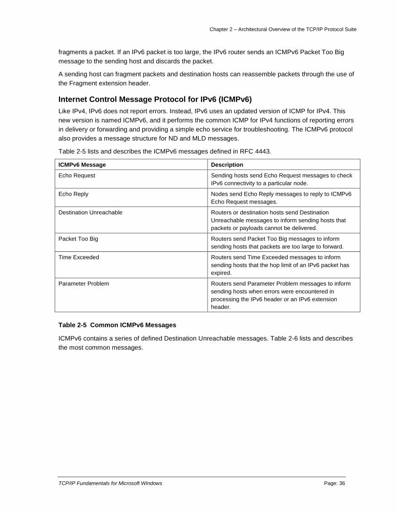
Chapter 2 – Architectural Overview of the TCP/IP Protocol Suite
TCP/IP Fundamentals for Microsoft Windows Page: 36
fragments a packet. If an IPv6 packet is too large, the IPv6 router sends an ICMPv6 Packet Too Big
message to the sending host and discards the packet.
A sending host can fragment packets and destination hosts can reassemble packets through the use of
the Fragment extension header.
Internet Control Message Protocol for IPv6 (ICMPv6)
Like IPv4, IPv6 does not report errors. Instead, IPv6 uses an updated version of ICMP for IPv4. This
new version is named ICMPv6, and it performs the common ICMP for IPv4 functions of reporting errors
in delivery or forwarding and providing a simple echo service for troubleshooting. The ICMPv6 protocol
also provides a message structure for ND and MLD messages.
Table 2-5 lists and describes the ICMPv6 messages defined in RFC 4443.
ICMPv6 Message Description
Echo Request Sending hosts send Echo Request messages to check
IPv6 connectivity to a particular node.
Echo Reply Nodes send Echo Reply messages to reply to ICMPv6
Echo Request messages.
Destination Unreachable Routers or destination hosts send Destination
Unreachable messages to inform sending hosts that
packets or payloads cannot be delivered.
Packet Too Big Routers send Packet Too Big messages to inform
sending hosts that packets are too large to forward.
Time Exceeded Routers send Time Exceeded messages to inform
sending hosts that the hop limit of an IPv6 packet has
expired.
Parameter Problem Routers send Parameter Problem messages to inform
sending hosts when errors were encountered in
processing the IPv6 header or an IPv6 extension
header.
Table 2-5 Common ICMPv6 Messages
ICMPv6 contains a series of defined Destination Unreachable messages. Table 2-6 lists and describes
the most common messages.

Chapter 2 – Architectural Overview of the TCP/IP Protocol Suite
TCP/IP Fundamentals for Microsoft Windows Page: 37
Destination Unreachable Message Description
No Route Found Routers send this message when they cannot find
routes to the destination IPv6 addresses in their local
IPv6 routing tables.
Communication Prohibited by Administrative Policy Routers send this message when a policy configured
on the router prohibits communication with the
destination. For example, this type of message is sent
when a firewall discards a packet.
Destination Address Unreachable IPv6 routers send this message when they cannot
resolve a destination’s MAC address.
Destination Port Unreachable Destination hosts send this message when an IPv6
packet containing a UDP message to a destination
UDP port does not correspond to a listening
application.
Table 2-6 Common ICMPv6 Destination Unreachable Messages
ICMPv6 does not make IPv6 a reliable protocol. ICMPv6 attempts to report errors and provide feedback
on specific conditions. ICMPv6 messages are carried as unacknowledged IPv6 packets and are
themselves unreliable.
Neighbor Discovery (ND)
ND is a set of ICMPv6 messages and processes that determine relationships between neighboring
nodes. ND replaces ARP, ICMP Router Discovery, and ICMP Redirect used in IPv4 and provides
additional functionality.
Hosts use ND to:
Discover neighboring routers.
Discover and automatically configure addresses and other configuration parameters.
Routers use ND to:
Advertise their presence, host addresses, and other configuration parameters.
Inform hosts of a better next-hop address to forward packets for a specific destination.
Nodes (both hosts and routers) use ND to:
Resolve the link-layer address (also known as a MAC address) of a neighboring node to which an IPv6
packet is being forwarded
Dynamically advertise changes in MAC addresses.
Determine whether a neighbor is still reachable.
Table 2-7 lists and describes the ND processes described in RFC 4861.

Chapter 2 – Architectural Overview of the TCP/IP Protocol Suite
TCP/IP Fundamentals for Microsoft Windows Page: 38
Neighbor Discovery Process Description
Router discovery The process by which a host discovers its neighboring
routers. For more information, see "Router Discovery"
later in this chapter.
Prefix discovery The process by which hosts discover the subnet
prefixes for local subnet destinations. For more
information about IPv6 subnet prefixes, see Chapter 3,
"IP Addressing."
Address autoconfiguration The process for configuring IPv6 addresses for
interfaces in either the presence or absence of an
address configuration server such as one running
Dynamic Host Configuration Protocol version 6
(DHCPv6). For more information, see "Address
Autoconfiguration" later in this chapter.
Address resolution The process by which nodes resolve a neighbor’s IPv6
address to its MAC address. Address resolution in
IPv6 is equivalent to ARP in IPv4. For more
information, see "Address Resolution" in this chapter.
Next-hop determination The process by which a node determines the next-hop
IPv6 address to which a packet is being forwarded
based on the destination address. The next-hop
address is either the destination address or the
address of a neighboring router.
Neighbor unreachability detection The process by which a node determines that the IPv6
layer of a neighbor is not capable of sending or
receiving packets.
Duplicate address detection The process by which a node determines that an
address considered for use is not already in use by a
neighboring node.
Redirect function The process of informing a host of a better first-hop
IPv6 address to reach a destination.
Table 2-7 IPv6 Neighbor Discovery Processes
Address Resolution
IPv6 address resolution consists of exchanging Neighbor Solicitation and Neighbor Advertisement
messages to resolve the next-hop IPv6 address to its corresponding MAC address. The sending host
sends a multicast Neighbor Solicitation message on the appropriate interface. The Neighbor Solicitation
message includes the MAC address of the sending node.
When the target node receives the Neighbor Solicitation message, it updates its neighbor cache
(equivalent to the ARP cache) with an entry for the source address and MAC address included in the
Neighbor Solicitation message. Next, the target node sends a unicast Neighbor Advertisement
message with its MAC address to the sender of the Neighbor Solicitation message.
Chapter 2 – Architectural Overview of the TCP/IP Protocol Suite
TCP/IP Fundamentals for Microsoft Windows Page: 39
After receiving the Neighbor Advertisement from the target, the sending host updates its neighbor
cache with an entry for the target node based upon the included MAC address. At this point, the
sending host and the target of the neighbor solicitation can send unicast IPv6 traffic.
Router Discovery
Router discovery is the process through which hosts attempt to discover the set of routers on the local
subnet. In addition to configuring a default router, IPv6 router discovery also configures the following:
The default setting for the Hop Limit field in the IPv6 header.
A determination of whether the node should use an address configuration protocol, such as Dynamic
Host Configuration Protocol for IPv6 (DHCPv6), for addresses and other configuration parameters.
The list of subnet prefixes defined for the link. Each subnet prefix contains both the IPv6 subnet prefix
and its valid and preferred lifetimes. If indicated, the host uses the subnet prefix to create an IPv6
address configuration without using an address configuration protocol. A subnet prefix also defines the
range of addresses for nodes on the local link.
The IPv6 router discovery processes are the following:
IPv6 routers periodically send multicast Router Advertisement messages on the subnet advertising their
existence as routers and other configuration parameters such as address prefixes and the default hop
limit.
IPv6 hosts on the local subnet receive the Router Advertisement messages and use their contents to
configure addresses, a default router, and other configuration parameters.
A host that is starting up sends a multicast Router Solicitation message. Upon receipt of a Router
Solicitation message, all routers on the local subnet send a unicast Router Advertisement message to
the host that sent the router solicitation. The host receives the Router Advertisement messages and
uses their contents to configure addresses, a default router, and other configuration parameters.
Address Autoconfiguration
A highly useful aspect of IPv6 is its ability to automatically configure itself without the use of an address
configuration protocol, such as Dynamic Host Configuration Protocol for IPv6 (DHCPv6). By default, an
IPv6 host can configure an address for use on the subnet for each interface. By using router discovery,
a host can also determine the addresses of routers, additional addresses, and other configuration
parameters. Router Advertisement messages indicate whether an address configuration protocol
should be used. RFC 4862 defines IPv6 address autoconfiguration.
For more information about IPv6 address autoconfiguration, see Chapter 6 “Dynamic Host
Configuration Protocol.”
Multicast Listener Discovery (MLD)
MLD is the IPv6 equivalent of IGMP version 2 for IPv4. MLD is a set of ICMPv6 messages exchanged
by routers and nodes, enabling routers to discover the set of IPv6 multicast addresses for which there
are listening nodes for each attached interface. Like IGMPv2, MLD discovers only those multicast
addresses that include at least one listener, not the list of individual multicast listeners for each
multicast address. RFC 2710 defines MLD.

Chapter 2 – Architectural Overview of the TCP/IP Protocol Suite
TCP/IP Fundamentals for Microsoft Windows Page: 40
Unlike IGMPv2, MLD uses ICMPv6 messages instead of defining its own message structure. The three
types of MLD messages are:
Multicast Listener Query Routers use Multicast Listener Query messages to query a subnet for
multicast listeners.
Multicast Listener Report Multicast listeners use Multicast Listener Report messages to either report
interest in receiving multicast traffic for a specific multicast address or to respond to a Multicast Listener
Query message.
Multicast Listener Done Multicast listeners use Multicast Listener Done messages to report that they
might be the last multicast group member on the subnet.
Windows Server 2008 and Windows Vista also support MLD version 2 (MLDv2), specified in RFC 3810,
which allows IPv6 hosts to register interest in source-specific multicast traffic with their local multicast
routers. A host running Windows Server 2008 or Windows Vista can register interest in receiving IPv6
multicast traffic from only specific source addresses (an include list) or from any source except specific
source addresses (an exclude list).
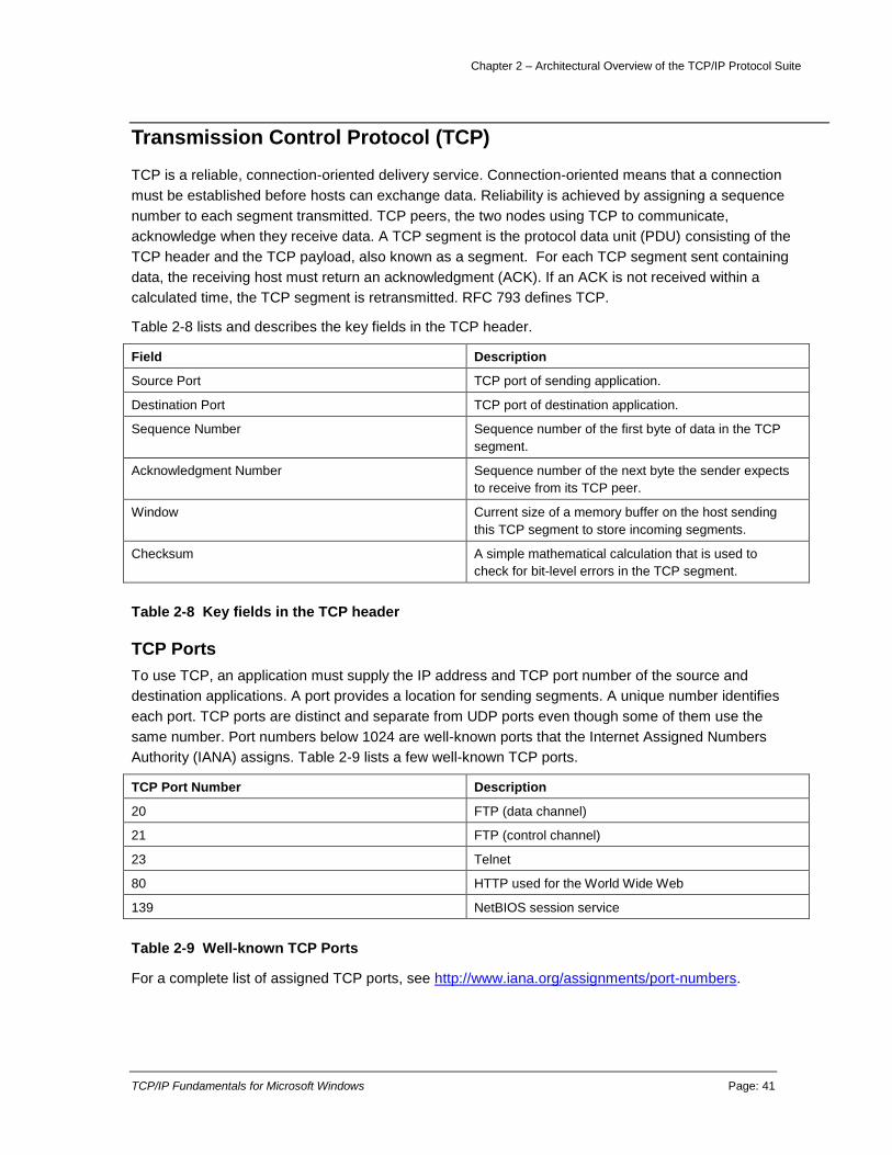
Chapter 2 – Architectural Overview of the TCP/IP Protocol Suite
TCP/IP Fundamentals for Microsoft Windows Page: 41
Transmission Control Protocol (TCP)
TCP is a reliable, connection-oriented delivery service. Connection-oriented means that a connection
must be established before hosts can exchange data. Reliability is achieved by assigning a sequence
number to each segment transmitted. TCP peers, the two nodes using TCP to communicate,
acknowledge when they receive data. A TCP segment is the protocol data unit (PDU) consisting of the
TCP header and the TCP payload, also known as a segment. For each TCP segment sent containing
data, the receiving host must return an acknowledgment (ACK). If an ACK is not received within a
calculated time, the TCP segment is retransmitted. RFC 793 defines TCP.
Table 2-8 lists and describes the key fields in the TCP header.
Field Description
Source Port TCP port of sending application.
Destination Port TCP port of destination application.
Sequence Number Sequence number of the first byte of data in the TCP
segment.
Acknowledgment Number Sequence number of the next byte the sender expects
to receive from its TCP peer.
Window Current size of a memory buffer on the host sending
this TCP segment to store incoming segments.
Checksum A simple mathematical calculation that is used to
check for bit-level errors in the TCP segment.
Table 2-8 Key fields in the TCP header
TCP Ports
To use TCP, an application must supply the IP address and TCP port number of the source and
destination applications. A port provides a location for sending segments. A unique number identifies
each port. TCP ports are distinct and separate from UDP ports even though some of them use the
same number. Port numbers below 1024 are well-known ports that the Internet Assigned Numbers
Authority (IANA) assigns. Table 2-9 lists a few well-known TCP ports.
TCP Port Number Description
20 FTP (data channel)
21 FTP (control channel)
23 Telnet
80 HTTP used for the World Wide Web
139 NetBIOS session service
Table 2-9 Well-known TCP Ports
For a complete list of assigned TCP ports, see http://www.iana.org/assignments/port-numbers.

Chapter 2 – Architectural Overview of the TCP/IP Protocol Suite
TCP/IP Fundamentals for Microsoft Windows Page: 42
TCP Three-Way Handshake
A TCP connection is initialized through a three-way handshake. The purpose of the three-way
handshake is to synchronize the sequence number and acknowledgment numbers of both sides of the
connection and to exchange TCP window sizes. The following steps outline the process for the
common situation when a client computer contacts a server computer:
1. The client sends a TCP segment to the server with an initial sequence number for the connection and
a window size indicating the size of a buffer on the client to store incoming segments from the server.
2. The server sends back a TCP segment containing its chosen initial sequence number, an
acknowledgment of the client’s sequence number, and a window size indicating the size of a buffer
on the server to store incoming segments from the client.
3. The client sends a TCP segment to the server containing an acknowledgment of the server’s
sequence number.
TCP uses a similar handshake process to end a connection. This guarantees that both hosts have
finished transmitting and that all data was received.

Chapter 2 – Architectural Overview of the TCP/IP Protocol Suite
TCP/IP Fundamentals for Microsoft Windows Page: 43
User Datagram Protocol (UDP)
UDP provides a connectionless datagram service that offers unreliable, best-effort delivery of data
transmitted in messages. This means that neither the arrival of datagrams nor the correct sequencing of
delivered packets is guaranteed. UDP does not retransmit lost data. UDP messages consist of a UDP
header and a UDP payload, also known as a message. RFC 768 defines UDP.
Applications use UDP if they do not require an acknowledgment of receipt of data, and they typically
transmit small amounts of data at one time. NetBIOS name service, NetBIOS datagram service, and
SNMP are examples of services and applications that use UDP.
Table 2-10 lists and describes the key fields in the UDP header.
Field Description
Source Port UDP port of sending application.
Destination Port UDP port of destination application.
Checksum A simple mathematical calculation that is used to
check for bit-level errors in the UDP message.
Table 2-10 Key Fields in the UDP Header
UDP Ports
To use UDP, an application must supply the IP address and UDP port number of the source and
destination applications. A port provides a location for sending messages. A unique number identifies
each port. UDP ports are distinct and separate from TCP ports even though some of them use the
same number. Just like TCP ports, UDP port numbers below 1024 are well-known ports that IANA
assigns. Table 2-11 lists a few well-known UDP ports.
UDP Port Number Description
53 Domain Name System (DNS) name queries
69 Trivial File Transfer Protocol (TFTP)
137 NetBIOS name service
138 NetBIOS datagram service
161 SNMP
Table 2-11 Well-known UDP ports
For a complete list of assigned UDP ports, see http://www.iana.org/assignments/port-numbers.

Chapter 2 – Architectural Overview of the TCP/IP Protocol Suite
TCP/IP Fundamentals for Microsoft Windows Page: 44
Packet Multiplexing and Demultiplexing
When a sending host sends an IPv4 or IPv6 packet, it includes information in the packet so that the
data within the packet can be delivered to the correct application on the destination. The inclusion of
identifiers so that data can be delivered to one of multiple entities in each layer of a layered architecture
is known as multiplexing. Multiplexing information for IP packets consists of identifying the node on the
network, the IP upper layer protocol, and for TCP and UDP, the port corresponding to the application to
which the data is destined. The destination host uses these identifiers to demultiplex, or deliver the data
layer by layer, to the correct destination application. The IP packet also includes information for the
destination host to send a response.
IP contains multiplexing information to do the following:
Identify the sending node (the Source IP Address field in the IPv4 header or the Source Address field in
the IPv6 header).
Identify the destination node (the Destination IP Address field in the IPv4 header or the Destination
Address in the IPv6 header).
Identify the upper layer protocol above the IPv4 or IPv6 Internet layer (the Protocol field in the IPv4
header or the Next Header field of the IPv6 header).
For TCP segments and UDP messages, identify the application from which the message was sent (the
Source Port in the TCP or UDP header).
For TCP segments and UDP messages, identify the application to which the message is destined (the
Destination Port in the TCP or UDP header).
TCP and UDP ports can use any number between 0 and 65,535. Port numbers for client-side
applications are typically dynamically assigned when there is a request for service, and IANA pre-
assigns port numbers for well-known server-side applications. The complete list of pre-assigned port
numbers is listed on http://www.iana.org/assignments/port-numbers.
All of this information is used to provide multiplexing information so that:
The packet can be forwarded to the correct destination.
The destination can use the packet payload to deliver the data to the correct application.
The receiving application can send a response.
When a packet is sent, this information is used in the following ways:
The routers that forward IPv4 or IPv6 packets use the Destination IP Address field in the IPv4 header or
the Destination Address in the IPv6 header to deliver the packet to the correct node on the network.
The destination node uses the Protocol field in the IPv4 header or the Next Header field of the IPv6
header to deliver the packet payload to the correct upper-layer protocol.
For TCP segments and UDP messages, the destination node uses the Destination Port field in the TCP
or UDP header to demultiplex the data within the TCP segment or UDP message to the correct
application.

Chapter 2 – Architectural Overview of the TCP/IP Protocol Suite
TCP/IP Fundamentals for Microsoft Windows Page: 45
Figure 2-5 shows an example of a DNS Name Query Request message in an IPv4 packet with a
destination IP address of 131.107.89.223 being demultiplexed to the DNS service.
Figure 2-5 Example of IPv4 packet demultiplexing

Chapter 2 – Architectural Overview of the TCP/IP Protocol Suite
TCP/IP Fundamentals for Microsoft Windows Page: 46
Application Programming Interfaces
Windows networking applications use two main application programming interfaces (APIs) to access
TCP/IP services in Windows: Windows Sockets and NetBIOS. Figure 2-6 shows these APIs and the
possible data flows when using them.
Figure 2-6 Architecture of the Windows Sockets and NetBIOS APIs
Some architectural differences between the Windows Sockets and NetBIOS APIs are the following:
NetBIOS over TCP/IP (NetBT) is defined for operation over IPv4. Windows Sockets operates over both
IPv4 and IPv6.
Windows Sockets applications can operate directly over the IPv4 or IPv6 Internet layers, without the
use of TCP or UDP. NetBIOS operates over TCP and UDP only.
Windows Sockets
Windows Sockets is a commonly used, modern API for networking applications in Windows. The
TCP/IP services and tools supplied with Windows are examples of Windows Sockets applications.
Windows Sockets provides services that allow applications to use a specific IP address and port, initiate
and accept a connection to a specific destination IP address and port, send and receive data, and close
a connection.

Chapter 2 – Architectural Overview of the TCP/IP Protocol Suite
TCP/IP Fundamentals for Microsoft Windows Page: 47
There are three types of sockets:
A stream socket, which provides a two-way, reliable, sequenced, and unduplicated flow of data using
TCP.
A datagram socket, which provides bidirectional flow of data using UDP.
A raw socket, which allows protocols to access IP directly, without using TCP or UDP.
A socket functions as an endpoint for network communication. An application creates a stream or
datagram socket by specifying three items: the IP address of the host, the type of service (TCP for
connection-based service and UDP for connectionless), and the port the application is using. Two
sockets, one for each end of the connection, form a bidirectional communications path. For raw
sockets, the application must specify the entire IP payload.
NetBIOS
NetBIOS is an older API that provides name management, datagram, and session services to NetBIOS
applications. An application program that uses the NetBIOS interface API for network communication
can be run on any protocol implementation that supports the NetBIOS interface. Examples of Windows
applications and services that use NetBIOS are file and printer sharing and the Computer Browser
service.
NetBIOS also defines a protocol that functions at the OSI Session layer. This layer is implemented by
the underlying protocol implementation, such as NetBIOS over TCP/IP (NetBT), which RFCs 1001 and
1002 define. The NetBIOS name service uses UDP port 137. The NetBIOS datagram service uses
UDP port 138. The NetBIOS session service uses TCP port 139.
For more information about NetBIOS and NetBT, see Chapter 11, "NetBIOS over TCP/IP."

Chapter 2 – Architectural Overview of the TCP/IP Protocol Suite
TCP/IP Fundamentals for Microsoft Windows Page: 48
TCP/IP Naming Schemes in Windows
Although IP is designed to work with the 32-bit (IPv4) and 128-bit (IPv6) addresses of sending and
destination hosts, computers users are much better at using and remembering names than IP
addresses. If a name is used as an alias for an IP address, mechanisms must exist for assigning
names to IP addresses, ensuring their uniqueness, and for resolving the name to its IP address.
TCP/IP components of Windows use separate mechanisms for assigning and resolving host names
(used by Windows Sockets applications) and NetBIOS names (used by NetBIOS applications).
Host Names
A host name is an alias assigned to an IP node to identify it as a TCP/IP host. The host name can be
up to 255 characters long and can contain alphabetic and numeric characters and the “-” and “.”
characters. Multiple host names can be assigned to the same host.
Windows Sockets applications, such as Internet Explorer and the Ping tool, can use one of two values
to refer to the destination: the IP address or a host name. When the user specifies an IP address, name
resolution is not needed. When the user specifies a host name, the host name must be resolved to an
IP address before IP-based communication with the target resource can begin.
Host names can take various forms. The two most common forms are a nickname and a fully qualified
domain name (FQDN). A nickname is an alias to an IP address that individual people can assign and
use. An FQDN is a structured name, such as www.microsoft.com, that follows the Internet conventions
used in DNS.
For information about how TCP/IP components in Windows resolve host names, see Chapter 7, “Host
Name Resolution.” For more information about DNS, see Chapter 8, “Domain Name System Overview.”
NetBIOS Names
A NetBIOS name is a 16-byte name that identifies a NetBIOS application on the network. A NetBIOS
name is either a unique (exclusive) or group (nonexclusive) name. When a NetBIOS application
communicates with a specific NetBIOS application on a specific computer, a unique name is used.
When a NetBIOS process communicates with multiple NetBIOS applications on multiple computers, a
group name is used.
The NetBIOS name identifies applications at the Session layer of the OSI model. For example, the
NetBIOS Session service operates over TCP port 139. Because all NetBT session requests are
addressed to TCP destination port 139, a NetBIOS application must use the destination NetBIOS name
when it establishes a NetBIOS session.
An example of a process using a NetBIOS name is the file and print sharing server service on a
Windows–based computer. When your computer starts up, the server service registers a unique
NetBIOS name based on your computer’s name. The exact name used by the server service is the 15-
character computer name plus a 16th character of 0x20. If the computer name is not 15 characters
long, it is padded with spaces up to 15 characters long. Other network services also use the computer
name to build their NetBIOS names, and the 16th character is typically used to identify each service.
When you attempt to make a file-sharing connection to a computer running Windows by specifying the
computer’s name, the Server service on the file server that you specify corresponds to a specific

Chapter 2 – Architectural Overview of the TCP/IP Protocol Suite
TCP/IP Fundamentals for Microsoft Windows Page: 49
NetBIOS name. For example, when you attempt to connect to the computer called CORPSERVER, the
NetBIOS name corresponding to the Server service is CORPSERVER <20>. (Note the padding using
the space character.) Before a file and print sharing connection can be established, a TCP connection
must be created. For a TCP connection to be created, the NetBIOS name CORPSERVER <20> must
be resolved to an IPv4 address. NetBIOS name resolution is the process of mapping a NetBIOS name
to an IPv4 address.
For more information about NetBT and NetBIOS name resolution methods, see Chapter 11, “NetBIOS
over TCP/IP.”

Chapter 2 – Architectural Overview of the TCP/IP Protocol Suite
TCP/IP Fundamentals for Microsoft Windows Page: 50
Chapter Summary
The key information in this chapter is the following:
The TCP/IP protocol suite maps to the four layers of the DARPA model: Application, Transport,
Internet, and Network Interface.
The protocols of the IPv4 Internet layer consist of ARP, IP (IPv4), ICMP, and IGMP.
The protocols of the IPv6 Internet layer consist of IPv6, ICMPv6, ND, and MLD.
The protocols of the Transport layer include TCP and UDP. TCP is a reliable, connection-oriented
delivery service. UDP provides a connectionless datagram service that offers unreliable, best-effort
delivery of data transmitted in messages.
IP packets are multiplexed and demultiplexed between applications based on fields in the IPv4, IPv6,
TCP, and UDP headers.
TCP/IP components in Windows support two main APIs for networking applications: Windows Sockets
and NetBIOS. Windows Sockets is a modern API that allows applications to manage stream sockets,
datagram sockets, and raw sockets. NetBIOS is an older API that allows applications to manage
NetBIOS names, datagrams, and sessions.
TCP/IP components in Windows support two naming schemes for networking applications: host names
(used by Windows Sockets applications) and NetBIOS names (used by NetBIOS applications).

Chapter 2 – Architectural Overview of the TCP/IP Protocol Suite
TCP/IP Fundamentals for Microsoft Windows Page: 51
Chapter Glossary
address autoconfiguration – The IPv6 ND process of automatically configuring IPv6 addresses on an
interface.
address resolution – The IPv4 (using ARP) or IPv6 (using ND) process that resolves the MAC address
for a next-hop IP address.
Address Resolution Protocol (ARP) – A protocol that uses broadcast traffic on the local network to
resolve an IPv4 address to its MAC address.
ARP – See Address Resolution Protocol.
ARP cache – A table for each interface of static or dynamically resolved IPv4 addresses and their
corresponding MAC addresses.
ICMP – See Internet Control Message Protocol.
ICMPv6 – Internet Control Message Protocol for IPv6.
IGMP – See Internet Group Management Protocol.
Internet Control Message Protocol (ICMP) – A protocol in the IPv4 Internet layer that reports errors and
provides troubleshooting facilities.
Internet Control Message Protocol for IPv6 (ICMPv6) – A protocol in the IPv6 Internet layer that reports
errors, provides troubleshooting facilities, and hosts ND and MLD messages.
Internet Group Management Protocol (IGMP) – A protocol in the IPv4 Internet layer that manages
multicast group membership on a subnet.
Internet Protocol (IP) – For IPv4, a routable protocol in the IPv4 Internet layer that addresses, routes,
fragments, and reassembles IPv4 packets. Also used to denote both IPv4 and IPv6 sets of protocols.
IP – See Internet Protocol.
IPv4 – The Internet layer in widespread use on the Internet and on private intranets. Another term for
IP.
IPv6 – The new Internet layer that will eventually replace the IPv4 Internet layer.
MLD – See Multicast Listener Discovery.
Multicast Listener Discovery (MLD) – A set of three ICMPv6 messages that hosts and routers use to
manage multicast group membership on a subnet.
name resolution – The process of resolving a name to an address.
ND – See Neighbor Discovery.
neighbor cache – A cache maintained by every IPv6 node that stores the IPv6 address of a neighbor
and its corresponding MAC address. The neighbor cache is equivalent to the ARP cache in IPv4.
Neighbor Discovery (ND) – A set of ICMPv6 messages and processes that determine relationships
between neighboring nodes. Neighbor Discovery replaces ARP, ICMP router discovery, and the ICMP
Redirect message used in IPv4.

Chapter 2 – Architectural Overview of the TCP/IP Protocol Suite
TCP/IP Fundamentals for Microsoft Windows Page: 52
Network Basic Input/Output System (NetBIOS) – A standard API for user applications to manage
NetBIOS names and access NetBIOS datagram and session services.
NetBIOS – See Network Basic Input/Output System.
router discovery – A Neighbor Discovery process in which a host discovers the local routers on an
attached subnet.
TCP – See Transmission Control Protocol.
Transmission Control Protocol (TCP) – A reliable, connection-oriented Transport layer protocol that
runs on top of IP.
UDP – See User Datagram Protocol
User Datagram Protocol (UDP) – An unreliable, connectionless Transport layer protocol that runs on
top of IP.
Windows Sockets – A commonly used application programming interface (API) that Windows
applications use to transfer data using TCP/IP.

Chapter 3 – IP Addressing
TCP/IP Fundamentals for Microsoft Windows Page: 53
Chapter 3 – IP Addressing
Abstract
This chapter describes the details of addressing for both IPv4 and IPv6. Network administrators need a thorough
understanding of both types of addressing to administer Transmission Control Protocol/Internet Protocol (TCP/IP)
networks and troubleshoot TCP/IP-based communication. This chapter discusses in detail the types of Internet Protocol
version 4 (IPv4) and Internet Protocol version 6 (IPv6) addresses, how they are expressed, and the types of unicast
addresses assigned to network node interfaces.
Chapter 3 – IP Addressing
TCP/IP Fundamentals for Microsoft Windows Page: 54
Chapter Objectives
After completing this chapter, you will be able to:
Describe the syntax for IPv4 addresses and address prefixes, and convert between binary and decimal
numbers.
List the three types of IPv4 addresses, and give examples of each type.
Describe the differences between public, private, and illegal IPv4 addresses.
Describe the syntax for IPv6 addresses and address prefixes, and convert between binary and
hexadecimal numbers.
List the three types of IPv6 addresses, and give examples of each type.
Describe the differences between global, unique local, and link-local unicast IPv6 addresses.
Convert an Institute of Electrical and Electronics Engineers (IEEE) 802 address to an IPv6 interface
identifier.
Compare addresses and addressing concepts between IPv4 and IPv6.

Chapter 3 – IP Addressing
TCP/IP Fundamentals for Microsoft Windows Page: 55
IPv4 Addressing
An IP address is an identifier that is assigned at the Internet layer to an interface or a set of interfaces.
Each IP address can identify the source or destination of IP packets. For IPv4, every node on a network
has one or more interfaces, and you can enable TCP/IP on each of those interfaces. When you enable
TCP/IP on an interface, you assign it one or more logical IPv4 addresses, either automatically or
manually. The IPv4 address is a logical address because it is assigned at the Internet layer and has no
relation to the addresses that are used at the Network Interface layer. IPv4 addresses are 32 bits long.
IPv4 Address Syntax
If network administrators expressed IPv4 addresses using binary notation, each address would appear
as a 32-digit string of 1s and 0s. Because such strings are cumbersome to express and remember,
administrators use dotted decimal notation, in which periods (or dots) separate four decimal numbers
(from 0 to 255). Each decimal number, known as an octet, represents 8 bits (1 byte) of the 32-bit
address.
For example, the IPv4 address 11000000101010000000001100011000 is expressed as 192.168.3.24
in dotted decimal notation. To convert an IPv4 address from binary notation to dotted decimal notation,
you:
Segment it into 8-bit blocks: 11000000 10101000 00000011 00011000
Convert each block to decimal: 192 168 3 24
Separate the blocks with periods: 192.168.3.24
When referring to an IPv4 address, use the notation w.x.y.z. Figure 3-1 shows the IPv4 address
structure.
Figure 3-1 The IPv4 address in dotted decimal notation
To become adept at moving between binary and decimal formats, you can review the binary (Base2)
and decimal (Base10) numbering systems and how to convert between them. Although you can use the

Chapter 3 – IP Addressing
TCP/IP Fundamentals for Microsoft Windows Page: 56
calculator in Windows to convert between decimal and binary, you will better understand the
conversions if you can do them manually.
Converting from Binary to Decimal
The decimal numbering system uses the digits 0 through 9 and the exponential powers of 10 to express
a number. For example, the decimal number 207 is the sum of 2102 + 010
1 + 710
0. The binary
numbering system uses the digits 1 and 0 and the exponential powers of 2 to express a number. The
binary number 11001 is the sum of 124 + 12
3 + 02
2 + 02
1 + 12
0. Dotted decimal notation never
includes numbers that are larger than 255 because each decimal number represents 8 bits of a 32-bit
address. The largest number that 8 bits can express is 11111111 in binary, which is 255 in decimal.
Figure 3-2 shows an 8-bit binary number, the bit positions, and their decimal values.
Figure 3-2 An 8-bit binary number
To manually convert an 8-bit number from binary to decimal (starting at the top of Figure 3-2), do the
following:
1. If the eighth bit position equals 1, add 128 to the total.
2. If the seventh bit position equals 1, add 64 to the total.
3. If the sixth bit position equals 1, add 32 to the total.
4. If the fifth bit position equals 1, add 16 to the total.
5. If the fourth bit position equals 1, add 8 to the total.

Chapter 3 – IP Addressing
TCP/IP Fundamentals for Microsoft Windows Page: 57
6. If the third bit position equals to 1, add 4 to the total.
7. If the second bit position equals 1, add 2 to the total.
8. If the first bit position equals to 1, add 1 to the total.
For example, for the 8-bit binary number 10111001:
1. The eighth bit position equals 1. Add 128 to the total. The total is now 128.
2. The seventh bit position equals 0.
3. The sixth bit position equals 1. Add 32 to the total. The total is now 160.
4. The fifth bit position equals 1. Add 16 to the total. The total is now 176.
5. The fourth bit position equals 1. Add 8 to the total. The total is now 184.
6. The third bit position equals 0.
7. The second bit position equals 0.
8. The first bit position equals 1. Add 1 to the total. The total is now 185.
Therefore, 10111001 in binary is 185 in decimal.
In summary, to convert a binary number to its decimal equivalent, total the decimal equivalents for the
bit positions that are set to 1. If all 8 bits are set to 1, add 128 + 64 + 32 + 16 + 8 + 4 + 2 + 1 to get 255.
Converting from Decimal to Binary
To manually convert a number up to 255 from decimal notation to binary format (starting at the decimal
column of Figure 3-2), do the following:
1. If the number is larger than 127, place a 1 in the eighth bit position, and subtract 128 from the
number. Otherwise, place a 0 in the eighth bit position.
2. If the remaining number is larger than 63, place a 1 in the seventh bit position, and subtract 64 from
the number. Otherwise, place a 0 in the seventh bit position.
3. If the remaining number is larger than 31, place a 1 in the sixth bit position, and subtract 32 from the
number. Otherwise, place a 0 in the sixth bit position.
4. If the remaining number is larger than 15, place a 1 in the fifth bit position, and subtract 16 from the
number. Otherwise, place a 0 in the fifth bit position.
5. If the remaining number is larger than 7, place a 1 in the fourth bit position, and subtract 8 from the
number. Otherwise, place a 0 in the fourth bit position.
6. If the remaining number is larger than 3, place a 1 in the third bit position, and subtract 4 from the
number. Otherwise, place a 0 in the third bit position.
7. If the remaining number is larger than 1, place a 1 in the second bit position, and subtract 2 from the
number. Otherwise, place a 0 in the second bit position.
8. If the remaining number equals 1, place a 1 in the first bit position. Otherwise, place a 0 in the first bit
position.
Here is an example of converting the number 197 from decimal to binary:

Chapter 3 – IP Addressing
TCP/IP Fundamentals for Microsoft Windows Page: 58
1. Because 197 is larger than 127, place a 1 in the eighth bit position, and subtract 128 from 197,
leaving 69. The binary number so far is 1xxxxxxx.
2. Because 69 is larger than 63, place a 1 in the seventh bit position, and subtract 64 from 69, leaving
5. The binary number so far is 11xxxxxx.
3. Because 5 is not larger than 31, place a 0 in the sixth bit position. The binary number so far is
110xxxxx.
4. Because 5 is not larger than 15, place a 0 in the fifth bit position. The binary number so far is
1100xxxx.
5. Because 5 is not larger than 7, place a 0 in the fourth bit position. The binary number so far is
11000xxx.
6. Because 5 is larger than 3, place a 1 in the third bit position, and subtract 4 from 5, leaving 1. The
binary number so far is 110001xx.
7. Because 1 is not larger than 1, place a 0 in the second bit position. The binary number so far is
1100010x.
8. Because 1 equals 1, place a 1 in the first bit position. The final binary number is 11000101. The
decimal number 197 is equal to the binary number 11000101.
In summary, to convert from decimal to binary, verify whether the decimal number contains the
quantities represented by the bit positions from the eighth bit to the first bit. Starting from the eighth bit
quantity (128), if each quantity is present, set the bit in that bit position to 1. For example, the decimal
number 211 contains 128, 64, 16, 2, and 1. Therefore, 211 is 11010011 in binary notation.
IPv4 Address Prefixes
Each bit of a unique IPv4 address has a defined value. However, IPv4 address prefixes express ranges
of IPv4 addresses in which zero or more of the high-order bits are fixed at specific values and the rest
of the low-order variable bits are set to zero. Address prefixes are routinely used to express a range of
allowable addresses, subnet prefixes assigned to subnets, and routes.
To express an IPv4 address prefix, you must identify the number of high-order bits that are fixed and
their value. Then you can use prefix length notation or dotted decimal notation.
Prefix Length Notation
If you use prefix length notation, you express address prefixes as StartingAddress/PrefixLength, in
which:
StartingAddress is the dotted decimal expression of the first mathematically possible address in the
range. To form the starting address, set the fixed bits at their defined values, and set the remaining bits
to 0.
PrefixLength is the number of high-order bits in the address that are fixed.
For example, the IPv4 address prefix 131.107.0.0/16 specifies a range of 65,536 addresses. The prefix
length, 16, specifies that all addresses in the range begin with the same 16 bits as the starting address.
Because the first 16 bits of the starting address are fixed at 10000011 01101011 (131 107 in decimal),

Chapter 3 – IP Addressing
TCP/IP Fundamentals for Microsoft Windows Page: 59
all addresses in the range have 131 as the first octet and 107 as the second octet. With 16 variable bits
in the last two octets, there is a total of 216
or 65,536 possible addresses.
To specify an address prefix using prefix length notation, you create the starting address by setting all
variable bits to 0, you convert the address to dotted decimal notation, and then you add a slash and the
number of fixed bits (the prefix length) after the starting address.
The IPv4 address prefix 131.107.0.0/16 has 16 fixed bits (10000011 01101011). The starting address is
the first 16 bits that are fixed and then the last 16 bits that are set to 0, which is 10000011 01101011
00000000 00000000 or 131.107.0.0. Next, you would add a slash and specify the number of fixed bits
(/16) to express the address prefix as 131.107.0.0/16.
Prefix length notation is also known as Classless Inter-Domain Routing (CIDR) notation.
Dotted Decimal Notation
You can also express an IPv4 address prefix length as a 32-bit number in dotted decimal notation. To
use this method, set all fixed bits to 1, set all variable bits to 0, and convert the result to dotted decimal
notation. Continuing our previous example, set the 16 fixed bits to 1 and the 16 variable bits to 0. The
result is 11111111 11111111 00000000 00000000, or 255.255.0.0. The address prefix is expressed as
131.107.0.0, 255.255.0.0. Expressing the prefix length as a dotted decimal number in this way is also
known as network mask or subnet mask notation.
Table 3-1 lists the decimal value of an octet when you set the successive high-order bits of an 8-bit
number to 1.
Number of Bits Binary Decimal
0 00000000 0
1 10000000 128
2 11000000 192
3 11100000 224
4 11110000 240
5 11111000 248
6 11111100 252
7 11111110 254
8 11111111 255
Table 3-1 Decimal Values for Prefix Lengths
When you configure IPv4 address prefixes in Windows, you will use subnet mask notation more
commonly than prefix length notation. However, you must be familiar with both types of notation
because some Windows configuration dialog boxes require you to use prefix length notation rather than
subnet mask notation and because IPv6 supports prefix length notation only.
Types of IPv4 Addresses
Internet standards define the following types of IPv4 addresses:
Unicast

Chapter 3 – IP Addressing
TCP/IP Fundamentals for Microsoft Windows Page: 60
Assigned to a single network interface located on a specific subnet; used for one-to-one
communication.
Multicast
Assigned to one or more network interfaces located on various subnets; used for one-to-many
communication.
Broadcast
Assigned to all network interfaces located on a subnet; used for one-to-everyone on a subnet
communication.
The following sections describe these types of addresses in detail.
IPv4 Unicast Addresses
The IPv4 unicast address identifies an interface’s location on the network in the same way that a street
address identifies a house on a city block. Just as a street address must identify a unique residence, an
IPv4 unicast address must be globally unique and have a uniform format.
Each IPv4 unicast address includes a subnet prefix and a host ID portion.
The subnet prefix (also known as a network identifier or network address) portion of an IPv4 unicast
address identifies the set of interfaces that are located on the same physical or logical network
segment, whose boundaries are defined by IPv4 routers. A network segment on TCP/IP networks is
also known as a subnet or a link. All nodes on the same physical or logical subnet must use the same
subnet prefix, and the subnet prefix must be unique within the entire TCP/IP network.
The host ID (also known as a host address) portion of an IPv4 unicast address identifies a network
node's interface on a subnet. The host ID must be unique within the network segment.
Figure 3-3 illustrates the structure of an example unicast IPv4 address.
Figure 3-3 Structure of an example unicast IPv4 address
If the subnet prefix is unique to the TCP/IP network and the host ID is unique on the network segment,
the entire IPv4 unicast address is unique to the entire TCP/IP network.
Internet Address Classes
The Internet community originally defined address classes to systematically assign address prefixes to
networks of varying sizes. The class of address defined how many bits were used for the subnet prefix
and how many bits were used for the host ID. Address classes also defined the possible number of
networks and the number of hosts per network. Of five address classes, class A, B, and C addresses
were reserved for IPv4 unicast addresses. Class D addresses were reserved for IPv4 multicast
addresses, and class E addresses were reserved for experimental uses.
Class A address prefixes were assigned to networks with very large numbers of hosts. The prefix length
of Class A address prefixes is only 8 bits, allowing the remaining 24 bits to identify up to 16,777,214

Chapter 3 – IP Addressing
TCP/IP Fundamentals for Microsoft Windows Page: 61
host IDs. However, the short prefix length limits the number of networks that can receive class A
address prefixes to 126. First, the high-order bit in class A address prefixes is always set to 0. That
convention decreases the number of class A address prefixes from 256 to 128. Second, addresses in
which the first eight bits are set to 00000000 cannot be assigned because they constitute a reserved
address prefix. Third, addresses in which the first eight bits are set to 01111111 (127 in decimal) cannot
be assigned because they are reserved for loopback addresses. Those last two conventions decrease
the number of class A address prefixes from 128 to 126.
For any IPv4 address prefix, the two host IDs in which all the host bits are set to 0 (the all-zeros host
ID) or to 1 (the all-ones host ID) are reserved and cannot be assigned to network node interfaces. This
convention reduces the number of host IDs in each class A network from 16,777,216 (224
) to
16,777,214.
Figure 3-4 illustrates the structure of class A addresses.
Figure 3-4 Structure of class A addresses
Class B address prefixes were assigned to medium to large-sized networks. In addresses for these
networks, the first 16 bits specify a particular network, and the last 16 bits specify a particular host.
However, the two high-order bits in a class B address are always set to 10, which makes the address
prefix for all class B networks and addresses 128.0.0.0/2 (or 128.0.0.0, 192.0.0.0). With 14 bits to
express class B address prefixes and 16 bits to express host IDs, class B addresses can be assigned
to 16,384 networks with up to 65,534 hosts per network.
Figure 3-5 illustrates the structure of class B addresses.
Figure 3-5 Structure of class B addresses
Class C address prefixes were assigned to small networks. In addresses for these networks, the first 24
bits specify a particular network, and the last 8 bits specify particular hosts. However, the three high-
order bits in a class C address prefix are always set to 110, which makes the address prefix for all class
C networks and addresses 192.0.0.0/3 (or 192.0.0.0, 224.0.0.0). With 21 bits to express class C
address prefixes and 8 bits to express host IDs, class C addresses can be assigned to 2,097,152
networks with up to 254 hosts per network.
Figure 3-6 illustrates the structure of class C addresses.
Figure 3-6 Structure of class C addresses

Chapter 3 – IP Addressing
TCP/IP Fundamentals for Microsoft Windows Page: 62
Class D addresses are reserved for IPv4 multicast addresses. The four high-order bits in a class D
address are always set to 1110, which makes the address prefix for all class D addresses 224.0.0.0/4
(or 224.0.0.0, 240.0.0.0). For more information, see "IPv4 Multicast Addresses" in this chapter.
Class E addresses are reserved for experimental use. The high-order bits in a class E address are set
to 1111, which makes the address prefix for all class E addresses 240.0.0.0/4 (or 240.0.0.0, 240.0.0.0).
Table 3-2 summarizes the Internet address classes A, B, and C that can be used for IPv4 unicast
addresses.
Class Value for w Address Prefix
Portion
Host ID
Portion
Address
Prefixes
Host IDs
per
Address
Prefix
A 1-126 w x.y.z 126 16,277,214
B 128-191 w.x y.z 16,384 65,534
C 192-223 w.x.y z 2,097,152 254
Table 3-2 Internet Address Class Summary
Modern Internet Addresses
The Internet address classes are an obsolete method of allocating unicast addresses because it proved
inefficient. For example, a large organization with a class A address prefix can have up to 16,777,214
hosts. However, if the organization uses only 70,000 host IDs, 16,707,214 potential IPv4 unicast
addresses for the Internet are wasted.
Since 1993, IPv4 address prefixes are assigned to organizations based on the organization's actual
need for Internet-accessible IPv4 unicast addresses. This method is known as Classless Inter-Domain
Routing (CIDR). For example, an organization determines that it needs 2,000 Internet-accessible IPv4
unicast addresses. The Internet Corporation for Assigned Names and Numbers (ICANN) or an Internet
service provider (ISP) allocates an IPv4 address prefix in which 21 bits are fixed, leaving 11 bits for host
IDs. From the 11 bits for host IDs, you can create 2,046 possible IPv4 unicast addresses.
CIDR-based address allocations typically start at 24 bits for the address prefix and 8 bits for the host ID.
Table 3-3 lists the required number of host IDs and the corresponding prefix length for CIDR-based
address allocations.
Number of Host IDs Prefix Length Dotted Decimal
2–254 /24 255.255.255.0
255–510 /23 255.255.254.0
511–1,022 /22 255.255.252.0
1,021–2,046 /21 255.255.248.0
2,047–4,094 /20 255.255.240.0
4,095–8,190 /19 255.255.224.0
8,191–16,382 /18 255.255.192.0
16,383–32,766 /17 255.255.128.0
32,767–65,534 /16 255.255.0.0

Chapter 3 – IP Addressing
TCP/IP Fundamentals for Microsoft Windows Page: 63
Table 3-3 Host ID Requirements and CIDR-based Prefix Lengths
Public Addresses
If you want direct (routed) connectivity to the Internet, then you must use public addresses. If you want
indirect (proxied or translated) connectivity to the Internet, you can use either public or private
addresses. If your intranet is not connected to the Internet in any way, you can use any unicast IPv4
addresses that you want. However, you should use private addresses to avoid network renumbering if
your intranet ever directly connects to the Internet.
ICANN assigns public addresses, which consist of either historically allocated classful address prefixes
or, more recently, CIDR-based address prefixes that are guaranteed to be unique on the Internet. For
CIDR-based address prefixes, the value of w (the first octet) ranges from 1 to 126 and from 128 to 223,
with the exception of the private address prefixes described in the "Private Addresses" section of this
chapter.
When ICANN assigns a public address prefix to an organization, routes are added to the routers of the
Internet so that traffic matching the address prefix can reach the organization. For example, when an
organization is assigned an address prefix, that address prefix also exists as a route in the routers of
the Internet. IPv4 packets that are sent to an address within the assigned address prefix are routed to
the proper destination.
Illegal Addresses
Private organization intranets that do not need an Internet connection can choose any address scheme
they want, even using public address prefixes that ICANN has assigned to other networks. If the private
organization later decides to directly connect to the Internet, these addresses could conflict with existing
public addresses and become illegal addresses. Organizations with illegal addresses cannot receive
traffic at those addresses because the routers of the Internet send traffic destined to ICANN-allocated
address prefixes to the assigned organizations, not to the organizations using illegal addresses.
For example, a private organization chooses to use the 206.73.118.0/24 address prefix for its intranet.
ICANN has assigned that prefix to the Microsoft Corporation, and routes exist on the Internet routers to
send all packets for IPv4 addresses on 206.73.118.0/24 to Microsoft. As long as the private
organization does not connect to the Internet, it has no problem because the two address prefixes are
on separate IPv4 networks; therefore, the addresses are unique to each network. If the private
organization later connects directly to the Internet and continues to use the 206.73.118.0/24 address
prefix, any traffic sent through the Internet to those addresses will arrive at Microsoft, not the private
organization.
Private Addresses
Each IPv4 interface requires an IPv4 address that is unique within the IPv4 network. In the case of the
Internet, each IPv4 interface on a subnet connected to the Internet requires an IPv4 address that is
unique within the Internet. As the Internet grew, organizations connecting to it required a public address
for each interface on their intranets. This requirement placed a huge demand on the pool of available
public addresses.
When analyzing the addressing needs of organizations, the designers of the Internet noted that, for
many organizations, most of the hosts did not require direct connectivity to the Internet. Those hosts

Chapter 3 – IP Addressing
TCP/IP Fundamentals for Microsoft Windows Page: 64
that did require a specific set of Internet services, such as Web access and e-mail, typically accessed
the Internet services through Application layer gateways, such as proxy servers and e-mail servers. The
result is that most organizations required only a few public addresses for those nodes (such as proxies,
servers, routers, firewalls, and translators) that were directly connected to the Internet.
Hosts within the organization that do not require direct access to the Internet required IPv4 addresses
that do not duplicate already-assigned public addresses. To solve this addressing problem, the Internet
designers reserved a portion of the IPv4 address space for private addresses. IPv4 addresses in the
private address space are known as private addresses and never assigned as public addresses.
Because the public and private address spaces do not overlap, private addresses never duplicate
public addresses.
RFC 1918 defines the following address prefixes for the private address space:
10.0.0.0/8 (10.0.0.0, 255.0.0.0)
Allows the following range of valid IPv4 unicast addresses: 10.0.0.1 to 10.255.255.254. The
10.0.0.0/8 address prefix has 24 host bits that you can use for any addressing scheme within a
private organization.
172.16.0.0/12 (172.16.0.0, 255.240.0.0)
Allows the following range of valid IPv4 unicast addresses: 172.16.0.1 to 172.31.255.254. The
172.16.0.0/12 address prefix has 20 host bits that you can use for any addressing scheme within a
private organization.
192.168.0.0/16 (192.168.0.0, 255.255.0.0)
Allows the following range of valid IPv4 unicast addresses: 192.168.0.1 to 192.168.255.254. The
192.168.0.0/16 address prefix has 16 host bits that you can use for any addressing scheme within a
private organization.
Because ICANN will never assign the IPv4 addresses in the private address space to an organization
connected to the Internet, Internet routers will never contain routes to private addresses. You cannot
connect to a private address over the Internet. Therefore, a host that has a private address must send
its Internet traffic requests to an Application layer gateway (such as a proxy server) that has a valid
public address or through a network address translation (NAT) device that translates the private
address into a valid public address.
Automatic Private IP Addressing
As described in Chapter 1, "Introduction to TCP/IP," you can configure an interface on a computer
running Windows so that the interface obtains an IPv4 address configuration automatically. If the
computer does not contact a Dynamic Host Configuration Protocol (DHCP) server, the computer uses
its alternate configuration, as specified on the Alternate Configuration tab of the properties dialog box
for the Internet Protocol Version 4 (TCP/IPv4) or Internet Protocol (TCP/IP) component.
If the Automatic Private IP Address option is selected on the Alternate Configuration tab and a
DHCP server cannot be found, TCP/IP in Windows uses Automatic Private IP Addressing (APIPA). The
TCP/IP component randomly selects an IPv4 address from the 169.254.0.0/16 address prefix and
assigns the subnet mask of 255.255.0.0. ICANN has reserved this address prefix, and it is not
reachable on the Internet. APIPA allows single-subnet Small Office/Home Office (SOHO) networks to

Chapter 3 – IP Addressing
TCP/IP Fundamentals for Microsoft Windows Page: 65
use TCP/IP without requiring an administrator to configure and update static addresses or administer a
DHCP server. APIPA does not configure a default gateway. Therefore, you can exchange traffic only
with other nodes on the subnet.
Special IPv4 Addresses
The following are special IPv4 addresses:
0.0.0.0
Known as the unspecified IPv4 address, it indicates the absence of an address. The unspecified
address is used only as a source address when the IPv4 node is not configured with an IPv4
address configuration and is attempting to obtain an address through a configuration protocol such
as DHCP.
127.0.0.1
Known as the IPv4 loopback address, it is assigned to an internal loopback interface. This interface
enables a node to send packets to itself.
Unicast IPv4 Addressing Guidelines
When you assign subnet prefixes to the subnets of an organization, use the following guidelines:
The subnet prefix must be unique within the IPv4 network.
If hosts can directly access the Internet from the subnet, you must use a public IPv4 address prefix
assigned by ICANN or an Internet service provider. If hosts cannot directly access the Internet from
the subnet, use either a legal public address prefix or a private address prefix that is unique within
your private intranet.
The subnet prefix cannot begin with the numbers 0 or 127.
Both of these values for the first octet are reserved, and you cannot use them for IPv4 unicast
addresses.
When you assign host IDs to the interfaces of nodes on an IPv4 subnet, use the following guidelines:
The host ID must be unique within the subnet.
You cannot use the all-zeros or all-ones host IDs.
When defining the range of valid IPv4 unicast addresses for a given address prefix, use the following
standard practice:
For the first IPv4 unicast address in the range, set all the host bits in the address to 0, except for the
low-order bit, which you set to 1.
For the last IPv4 unicast address in the range, set all the host bits in the address to 1, except for the
low-order bit, which you set to 0.
For example, to express the range of addresses for the address prefix 192.168.16.0/20:
The first IPv4 unicast address in the range is 11000000 10101000 00010000 00000001 (host bits are
underlined), or 192.168.16.1.

Chapter 3 – IP Addressing
TCP/IP Fundamentals for Microsoft Windows Page: 66
The last IPv4 unicast address in the range is 11000000 10101000 00011111 11111110 (host bits are
underlined), or 192.168.31.254.
Therefore, the range of addresses for the address prefix 192.168.16.0/20 is 192.168.16.1 to
192.168.31.254.
IPv4 Multicast Addresses
IPv4 uses multicast addresses to deliver single packets from one source to many destinations. On an
IPv4 intranet that is enabled for multicast, routers forward an IPv4 packet addressed to an IPv4
multicast address to the subnets on which hosts are listening to the traffic sent to the IPv4 multicast
address. IPv4 multicast efficiently delivers many types of communication from one source to many
destinations.
IPv4 multicast addresses are defined by the class D Internet address class: 224.0.0.0/4. IPv4 multicast
addresses range from 224.0.0.0 through 239.255.255.255. IPv4 multicast addresses for the
224.0.0.0/24 address prefix (224.0.0.0 through 224.0.0.255) are reserved for multicast traffic on a local
subnet.
For more information about IPv4 multicast addresses and processes, see Appendix B, "IP Multicast."
IPv4 Broadcast Addresses
IPv4 uses a set of broadcast addresses to deliver packets from one source to all interfaces on the
subnet. All the interfaces on the subnet process packets sent to IPv4 broadcast addresses. The
following are the types of IPv4 broadcast addresses:
Network broadcast
Formed by setting all the host bits to 1 for a classful address prefix. For example, 131.107.255.255
is a network broadcast address for the classful address prefix 131.107.0.0/16. Network broadcasts
send packets to all interfaces of a classful network. IPv4 routers do not forward network broadcast
packets.
Subnet broadcast
Formed by setting all the host bits to 1 for a classless address prefix. For example, 131.107.26.255
is a network broadcast address for the classless address prefix 131.107.26.0/24. Subnet
broadcasts are used to send packets to all hosts of a classless network. IPv4 routers do not forward
subnet broadcast packets.
For a classful address prefix, there is no subnet broadcast address, only a network broadcast
address. For a classless address prefix, there is no network broadcast address, only a subnet
broadcast address.
All-subnets-directed broadcast
Formed by setting the classful address prefix host bits to 1 for a classless address prefix. The all-
subnets-directed broadcast address is deprecated in RFC 1812. A packet addressed to the all-
subnets-directed broadcast address was defined to reach all hosts on all of the subnets of a
classful address prefix that has been subnetted. For example, 131.107.255.255 is the all-subnets-
directed broadcast address for the subnetted address prefix 131.107.26.0/24. The all-subnets-
directed broadcast address is the network broadcast address of the original classful address prefix.

Chapter 3 – IP Addressing
TCP/IP Fundamentals for Microsoft Windows Page: 67
Limited broadcast
Formed by setting all 32 bits of the IPv4 address to 1 (255.255.255.255). The limited broadcast
address is used for one-to-everyone delivery on the local subnet when the local subnet prefix is
unknown. IPv4 nodes typically use the limited broadcast address only during an automated
configuration process such as Boot Protocol (BOOTP) or DHCP. For example, a DHCP client must
use the limited broadcast address for all traffic sent before the DHCP server acknowledges the use
of the offered IPv4 address configuration.
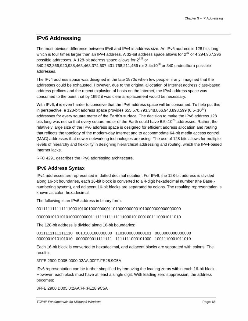
Chapter 3 – IP Addressing
TCP/IP Fundamentals for Microsoft Windows Page: 68
IPv6 Addressing
The most obvious difference between IPv6 and IPv4 is address size. An IPv6 address is 128 bits long,
which is four times larger than an IPv4 address. A 32-bit address space allows for 232
or 4,294,967,296
possible addresses. A 128-bit address space allows for 2128
or
340,282,366,920,938,463,463,374,607,431,768,211,456 (or 3.41038
or 340 undecillion) possible
addresses.
The IPv4 address space was designed in the late 1970s when few people, if any, imagined that the
addresses could be exhausted. However, due to the original allocation of Internet address class-based
address prefixes and the recent explosion of hosts on the Internet, the IPv4 address space was
consumed to the point that by 1992 it was clear a replacement would be necessary.
With IPv6, it is even harder to conceive that the IPv6 address space will be consumed. To help put this
in perspective, a 128-bit address space provides 655,570,793,348,866,943,898,599 (6.51023
)
addresses for every square meter of the Earth’s surface. The decision to make the IPv6 address 128
bits long was not so that every square meter of the Earth could have 6.51023
addresses. Rather, the
relatively large size of the IPv6 address space is designed for efficient address allocation and routing
that reflects the topology of the modern-day Internet and to accommodate 64-bit media access control
(MAC) addresses that newer networking technologies are using. The use of 128 bits allows for multiple
levels of hierarchy and flexibility in designing hierarchical addressing and routing, which the IPv4-based
Internet lacks.
RFC 4291 describes the IPv6 addressing architecture.
IPv6 Address Syntax
IPv4 addresses are represented in dotted decimal notation. For IPv6, the 128-bit address is divided
along 16-bit boundaries, each 16-bit block is converted to a 4-digit hexadecimal number (the Base16
numbering system), and adjacent 16-bit blocks are separated by colons. The resulting representation is
known as colon-hexadecimal.
The following is an IPv6 address in binary form:
0011111111111110001010010000000011010000000001010000000000000000
0000001010101010000000001111111111111110001010001001110001011010
The 128-bit address is divided along 16-bit boundaries:
0011111111111110 0010100100000000 1101000000000101 0000000000000000
0000001010101010 0000000011111111 1111111000101000 1001110001011010
Each 16-bit block is converted to hexadecimal, and adjacent blocks are separated with colons. The
result is:
3FFE:2900:D005:0000:02AA:00FF:FE28:9C5A
IPv6 representation can be further simplified by removing the leading zeros within each 16-bit block.
However, each block must have at least a single digit. With leading zero suppression, the address
becomes:
3FFE:2900:D005:0:2AA:FF:FE28:9C5A

Chapter 3 – IP Addressing
TCP/IP Fundamentals for Microsoft Windows Page: 69
Converting Between Binary and Hexadecimal
The hexadecimal numbering system uses the digits 0 through 9, A, B, C, D, E, and F and the
exponential powers of 16 to express a number. Table 3-4 lists decimal, hexadecimal, and binary
equivalents of the numbers 0-15.
Decimal Hexadecimal Binary
0 0 0000
1 1 0001
2 2 0010
3 3 0011
4 4 0100
5 5 0101
6 6 0110
7 7 0111
8 8 1000
9 9 1001
10 A 1010
11 B 1011
12 C 1100
13 D 1101
14 E 1110
15 F 1111
Table 3-4 Decimal, Hexadecimal, and Binary Conversions
To convert a hexadecimal number to a binary number, convert each hexadecimal digit to its 4-bit
equivalent. For example, to convert the hexadecimal number 0x03D8 to binary, convert each
hexadecimal digit (0, 3, D, and 8) to binary. Therefore, 0x03D8 is 0000 0011 1101 1000, or
0000001111011000.
To convert a binary number to a hexadecimal number, segment the binary number into 4-bit blocks
starting from the low-order bit. Then convert each 4-bit block to its hexadecimal equivalent. For
example, to convert the binary number 0110000110101110 to hexadecimal, first divide the entire
number into 4-bit blocks, which are 0110 0001 1010 1110. Then, convert each block to hexadecimal
digits, which are 0x61AE.
Although you can use the calculator in Windows Server 2003 or Windows XP to convert between
hexadecimal and binary, it helps you to better understand the conversions if you can do them manually.
To convert between decimal and hexadecimal, which you will not need often for IPv6 addresses, use
the Windows calculator.

Chapter 3 – IP Addressing
TCP/IP Fundamentals for Microsoft Windows Page: 70
Compressing Zeros
Some types of addresses contain long sequences of zeros. To further simplify the representation of
IPv6 addresses, you can compress a single contiguous sequence of 16-bit blocks set to 0 in the colon
hexadecimal format to “::”, known as double-colon.
For example, you can compress the unicast IPv6 address of FE80:0:0:0:2AA:FF:FE9A:4CA2 to
FE80::2AA:FF:FE9A:4CA2, and you can compress the multicast IPv6 address FF02:0:0:0:0:0:0:2 to
FF02::2.
You can use zero compression to compress only a single contiguous series of 16-bit blocks expressed
in colon hexadecimal notation. You cannot use zero compression to include part of a 16-bit block. For
example, you cannot express FF02:30:0:0:0:0:0:5 as FF02:3::5.
To determine how many 0 bits are represented by the “::”, you can count the number of blocks in the
compressed address, subtract this number from 8, and then multiply the result by 16. For example, the
address FF02::2 has two blocks (the “FF02” block and the “2” block), so the other six blocks of 16 bits
(96 bits total) have been compressed.
You can use zero compression only once in a given address. Otherwise, you could not determine the
number of 0 bits represented by each instance of “::”. If an address contains two series of zero blocks of
the same length and no series of zero blocks is longer, then by convention the left-most block is
expressed as “::”.
IPv6 Address Prefixes
You express IPv6 address ranges as address prefixes in the same manner as you express IPv4
address ranges using prefix length notation. For example, FF00::/8 is an address range, 2001:DB8::/32
is a route prefix, and 2001:DB8:0:2F3B::/64 is a subnet prefix. You do not express an address prefix
using a colon hexadecimal equivalent of an IPv4 subnet mask.
Types of IPv6 Addresses
IPv6 has three types of addresses:
Unicast
A unicast address identifies a single interface within the scope of the type of unicast address. With
the appropriate unicast routing topology, packets addressed to a unicast address are delivered to a
single interface. A unicast address is used for communication from one source to a single
destination.
Multicast
A multicast address identifies multiple interfaces. With the appropriate multicast routing topology,
packets addressed to a multicast address are delivered to all interfaces that are identified by the
address. A multicast address is used for communication from one source to many destinations, with
delivery to multiple interfaces.
Anycast
An anycast address identifies multiple interfaces. With the appropriate routing topology, packets
addressed to an anycast address are delivered to a single interface, the nearest interface that the
address identifies. The “nearest” interface is defined as being closest in terms of routing distance.

Chapter 3 – IP Addressing
TCP/IP Fundamentals for Microsoft Windows Page: 71
An anycast address is used for communication from one source to one of multiple destinations, with
delivery to a single interface.
IPv6 addresses always identify interfaces, not nodes. A node is identified by any unicast address
assigned to one of its interfaces.
RFC 4291 does not define any types of broadcast addresses. Instead, IPv6 multicast addresses are
used. For example, the subnet and limited broadcast addresses from IPv4 are replaced with the
reserved IPv6 multicast address of FF02::1.
IPv6 Unicast Addresses
The following types of addresses are unicast IPv6 addresses:
Global unicast addresses
Link-local addresses
Site-local addresses
Unique local addresses
Special IPv6 addresses
Transition addresses
Global Unicast Addresses
Global unicast addresses are equivalent to public IPv4 addresses. They are globally routable and
reachable on the IPv6 portion of the Internet, known as the IPv6 Internet.
Global unicast addresses can be aggregated or summarized to produce an efficient routing
infrastructure. The current IPv4-based Internet is a mixture of both flat and hierarchical routing, but the
IPv6-based Internet has been designed from its foundation to support efficient, hierarchical addressing
and routing. Global unicast addresses are unique across their scope, which is the entire IPv6 Internet.
For more information about routing infrastructure including route aggregation and summarization, see
Chapter 5, "IP Routing."
Figure 3-7 shows the general structure of a global unicast address as defined in RFC 3587.
Figure 3-7 Structure of a global unicast address as defined in RFC 3587
Figure 3-8 shows the structure of global unicast addresses being allocated by IANA at the time of this
writing, as defined in RFC 3587.
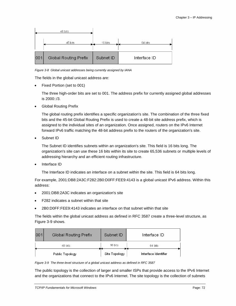
Chapter 3 – IP Addressing
TCP/IP Fundamentals for Microsoft Windows Page: 72
Figure 3-8 Global unicast addresses being currently assigned by IANA
The fields in the global unicast address are:
Fixed Portion (set to 001)
The three high-order bits are set to 001. The address prefix for currently assigned global addresses
is 2000::/3.
Global Routing Prefix
The global routing prefix identifies a specific organization's site. The combination of the three fixed
bits and the 45-bit Global Routing Prefix is used to create a 48-bit site address prefix, which is
assigned to the individual sites of an organization. Once assigned, routers on the IPv6 Internet
forward IPv6 traffic matching the 48-bit address prefix to the routers of the organization's site.
Subnet ID
The Subnet ID identifies subnets within an organization's site. This field is 16 bits long. The
organization's site can use these 16 bits within its site to create 65,536 subnets or multiple levels of
addressing hierarchy and an efficient routing infrastructure.
Interface ID
The Interface ID indicates an interface on a subnet within the site. This field is 64 bits long.
For example, 2001:DB8:2A3C:F282:2B0:D0FF:FEE9:4143 is a global unicast IPv6 address. Within this
address:
2001:DB8:2A3C indicates an organization's site
F282 indicates a subnet within that site
2B0:D0FF:FEE9:4143 indicates an interface on that subnet within that site
The fields within the global unicast address as defined in RFC 3587 create a three-level structure, as
Figure 3-9 shows.
Figure 3-9 The three-level structure of a global unicast address as defined in RFC 3587
The public topology is the collection of larger and smaller ISPs that provide access to the IPv6 Internet
and the organizations that connect to the IPv6 Internet. The site topology is the collection of subnets

Chapter 3 – IP Addressing
TCP/IP Fundamentals for Microsoft Windows Page: 73
within an organization’s site. The interface identifier identifies a specific interface on a subnet within an
organization’s site.
Local-use unicast addresses fall into two categories:
Link-local addresses are used between on-link neighbors and for Neighbor Discovery processes, which
define how nodes on an IPv6 subnet interact with hosts and routers.
Site-local addresses are used between nodes communicating with other nodes in the same site of an
organization’s intranet.
Link-Local Addresses
Nodes use link-local addresses when communicating with neighboring nodes on the same link, also
known as a subnet. For example, on a single-link IPv6 network with no router, link-local addresses are
used to communicate between hosts on the link. Link-local addresses are equivalent to APIPA IPv4
addresses autoconfigured on computers that are running Windows. The scope of a link-local address
(the region of the network across which the address is unique) is the local link.
A link-local address is required for Neighbor Discovery processes and is always automatically
configured, even in the absence of all other unicast addresses.
For more information about IPv6 address autoconfiguration for link-local addresses, see Chapter 6,
"Dynamic Host Configuration Protocol."
Figure 3-10 shows the structure of the link-local address.
Figure 3-10 Structure of the link-local address
Because the first 64 bits of the link-local address are fixed, the address prefix for all link-local addresses
is FE80::/64.
An IPv6 router never forwards link-local traffic beyond the link.
Site-Local Addresses
Site-local addresses are equivalent to the IPv4 private address space. Private intranets that do not
have a direct, routed connection to the IPv6 Internet can use site-local addresses without conflicting
with global addresses. Site-local addresses are not reachable from other sites, and routers must not
forward site-local traffic outside the site. Site-local addresses can be used in addition to global
addresses. The scope of a site-local address is a site (a portion of an organization network that has
defined geographical, topological, or network bandwidth boundaries).
Unlike link-local addresses, site-local addresses are not automatically configured and must be assigned
either through stateless or stateful address configuration.
Figure 3-11 shows the structure of the site-local address.
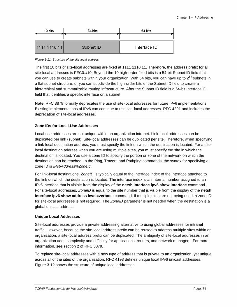
Chapter 3 – IP Addressing
TCP/IP Fundamentals for Microsoft Windows Page: 74
Figure 3-11 Structure of the site-local address
The first 10 bits of site-local addresses are fixed at 1111 1110 11. Therefore, the address prefix for all
site-local addresses is FEC0::/10. Beyond the 10 high-order fixed bits is a 54-bit Subnet ID field that
you can use to create subnets within your organization. With 54 bits, you can have up to 254
subnets in
a flat subnet structure, or you can subdivide the high-order bits of the Subnet ID field to create a
hierarchical and summarizable routing infrastructure. After the Subnet ID field is a 64-bit Interface ID
field that identifies a specific interface on a subnet.
Note RFC 3879 formally deprecates the use of site-local addresses for future IPv6 implementations.
Existing implementations of IPv6 can continue to use site-local addresses. RFC 4291 and includes the
deprecation of site-local addresses.
Zone IDs for Local-Use Addresses
Local-use addresses are not unique within an organization intranet. Link-local addresses can be
duplicated per link (subnet). Site-local addresses can be duplicated per site. Therefore, when specifying
a link-local destination address, you must specify the link on which the destination is located. For a site-
local destination address when you are using multiple sites, you must specify the site in which the
destination is located. You use a zone ID to specify the portion or zone of the network on which the
destination can be reached. In the Ping, Tracert, and Pathping commands, the syntax for specifying a
zone ID is IPv6Address%ZoneID.
For link-local destinations, ZoneID is typically equal to the interface index of the interface attached to
the link on which the destination is located. The interface index is an internal number assigned to an
IPv6 interface that is visible from the display of the netsh interface ipv6 show interface command.
For site-local addresses, ZoneID is equal to the site number that is visible from the display of the netsh
interface ipv6 show address level=verbose command. If multiple sites are not being used, a zone ID
for site-local addresses is not required. The ZoneID parameter is not needed when the destination is a
global unicast address.
Unique Local Addresses
Site-local addresses provide a private addressing alternative to using global addresses for intranet
traffic. However, because the site-local address prefix can be reused to address multiple sites within an
organization, a site-local address prefix can be duplicated. The ambiguity of site-local addresses in an
organization adds complexity and difficulty for applications, routers, and network managers. For more
information, see section 2 of RFC 3879.
To replace site-local addresses with a new type of address that is private to an organization, yet unique
across all of the sites of the organization, RFC 4193 defines unique local IPv6 unicast addresses.
Figure 3-12 shows the structure of unique local addresses.
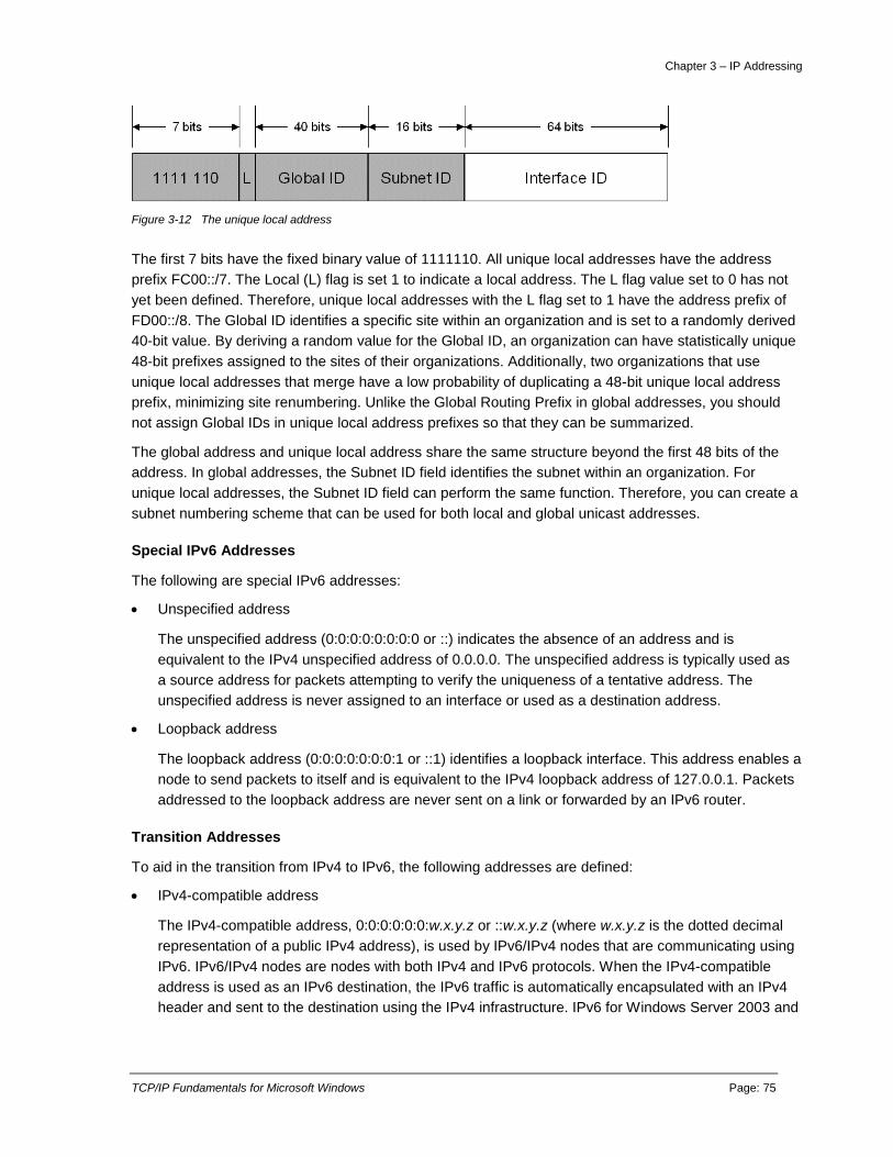
Chapter 3 – IP Addressing
TCP/IP Fundamentals for Microsoft Windows Page: 75
Figure 3-12 The unique local address
The first 7 bits have the fixed binary value of 1111110. All unique local addresses have the address
prefix FC00::/7. The Local (L) flag is set 1 to indicate a local address. The L flag value set to 0 has not
yet been defined. Therefore, unique local addresses with the L flag set to 1 have the address prefix of
FD00::/8. The Global ID identifies a specific site within an organization and is set to a randomly derived
40-bit value. By deriving a random value for the Global ID, an organization can have statistically unique
48-bit prefixes assigned to the sites of their organizations. Additionally, two organizations that use
unique local addresses that merge have a low probability of duplicating a 48-bit unique local address
prefix, minimizing site renumbering. Unlike the Global Routing Prefix in global addresses, you should
not assign Global IDs in unique local address prefixes so that they can be summarized.
The global address and unique local address share the same structure beyond the first 48 bits of the
address. In global addresses, the Subnet ID field identifies the subnet within an organization. For
unique local addresses, the Subnet ID field can perform the same function. Therefore, you can create a
subnet numbering scheme that can be used for both local and global unicast addresses.
Special IPv6 Addresses
The following are special IPv6 addresses:
Unspecified address
The unspecified address (0:0:0:0:0:0:0:0 or ::) indicates the absence of an address and is
equivalent to the IPv4 unspecified address of 0.0.0.0. The unspecified address is typically used as
a source address for packets attempting to verify the uniqueness of a tentative address. The
unspecified address is never assigned to an interface or used as a destination address.
Loopback address
The loopback address (0:0:0:0:0:0:0:1 or ::1) identifies a loopback interface. This address enables a
node to send packets to itself and is equivalent to the IPv4 loopback address of 127.0.0.1. Packets
addressed to the loopback address are never sent on a link or forwarded by an IPv6 router.
Transition Addresses
To aid in the transition from IPv4 to IPv6, the following addresses are defined:
IPv4-compatible address
The IPv4-compatible address, 0:0:0:0:0:0:w.x.y.z or ::w.x.y.z (where w.x.y.z is the dotted decimal
representation of a public IPv4 address), is used by IPv6/IPv4 nodes that are communicating using
IPv6. IPv6/IPv4 nodes are nodes with both IPv4 and IPv6 protocols. When the IPv4-compatible
address is used as an IPv6 destination, the IPv6 traffic is automatically encapsulated with an IPv4
header and sent to the destination using the IPv4 infrastructure. IPv6 for Windows Server 2003 and

Chapter 3 – IP Addressing
TCP/IP Fundamentals for Microsoft Windows Page: 76
Windows XP supports IPv4-compatible addresses, but they are disabled by default. IPv6 for
Windows Server 2008 and Windows Vista does not support IPv4-compatible addresses.
IPv4-mapped address
The IPv4-mapped address, 0:0:0:0:0:FFFF:w.x.y.z or ::FFFF:w.x.y.z, represents an IPv4-only node
to an IPv6 node. IPv4-mapped addresses are used for internal representation only. The IPv4-
mapped address is never used as a source or destination address of an IPv6 packet. IPv6 for
Windows Server 2003 and Windows XP does not support IPv4-mapped addresses. IPv6 for
Windows Server 2008 and Windows Vista supports IPv4-mapped addresses.
6to4 address
The 6to4 address is used for communicating between two nodes running both IPv4 and IPv6 over
the Internet. You form the 6to4 address by combining the global prefix 2002::/16 with the 32 bits of
a public IPv4 address of the node, forming a 48-bit prefix. 6to4 is an IPv6 transition technology
described in RFC 3056.
ISATAP address
The Intra-Site Automatic Tunnel Addressing Protocol (ISATAP) defines ISATAP addresses used
between two nodes running both IPv4 and IPv6 over a private intranet. ISATAP addresses use the
locally administered interface ID ::0:5EFE:w.x.y.z in which w.x.y.z is a private IPv4 address and
::200:5EFE:w.x.y.z in which w.x.y.z is a public IPv4 address. You can combine the ISATAP
interface ID with any 64-bit prefix that is valid for IPv6 unicast addresses, including the link-local
address prefix (FE80::/64), unique local prefixes, and global prefixes. ISATAP is an IPv6 transition
technology described in RFC 4214.
Teredo address
The Teredo address is used for communicating between two nodes running both IPv4 and IPv6
over the Internet when one or both of the endpoints are located behind an IPv4 network address
translation (NAT) device. You form the Teredo address by combining the 2001::/32-bit Teredo
prefix with the public IPv4 address of a Teredo server and other elements. Teredo is an IPv6
transition technology described in RFC 4380.
For more information about IPv4-compatible, 6to4, ISATAP, and Teredo addresses, see Chapter 15,
"IPv6 Transition Technologies."
IPv6 Interface Identifiers
The last 64 bits of a unicast IPv6 address are the interface identifier that is unique to the 64-bit prefix of
the IPv6 address. IPv6 interface identifiers are determined as follows:
A permanent interface identifier that is randomly derived. This is the default for Windows Server 2008
and Windows Vista.
An interface identifier that is derived from the Extended Unique Identifier (EUI)-64 address. This is the
default for Windows Server 2003 and Windows XP.
A randomly generated interface identifier that changes over time to provide a level of anonymity.
An interface identifier that is assigned during stateful address autoconfiguration (for example, through
Dynamic Host Configuration Protocol for IP version 6 [DHCPv6]).

Chapter 3 – IP Addressing
TCP/IP Fundamentals for Microsoft Windows Page: 77
EUI-64 Address-based Interface Identifiers
RFC 4291 states that all unicast addresses that use the prefixes 001 through 111 must also use a 64-
bit interface identifier derived from the EUI-64 address, a 64-bit address that is defined by the IEEE.
EUI-64 addresses are either assigned to a network adapter or derived from IEEE 802 addresses.
A traditional interface identifier for a network adapter uses a 48-bit address called an IEEE 802
address. It consists of a 24-bit company ID (also called the manufacturer ID) and a 24-bit extension ID
(also called the board ID). The combination of the company ID, which is uniquely assigned to each
manufacturer of network adapters, and the board ID, which is uniquely assigned to each network
adapter at the time of assembly, produces a globally unique 48-bit address. This 48-bit address is also
called the physical, hardware, or MAC address.
Figure 3-13 shows the structure of the 48-bit IEEE 802 address.
Figure 3-13 Structure of the 48-bit IEEE 802 address
Defined bits within the IEEE 802 address are:
Universal/Local (U/L)
The next-to-the-low-order bit in the first byte indicates whether the address is universally or locally
administered. If the U/L bit is set to 0, the IEEE (through the designation of a unique company ID)
has administered the address. If the U/L bit is set to 1, the address is locally administered. The
network administrator has overridden the manufactured address and specified a different address.
The U/L bit is designated by the u in Figure 3-13.
Individual/Group (I/G)
The low order bit of the first byte indicates whether the address is an individual address (unicast) or
a group address (multicast). When set to 0, the address is a unicast address. When set to 1, the
address is a multicast address. The I/G bit is designated by the g in Figure 3-13.
For a typical 802 network adapter address, both the U/L and I/G bits are set to 0, corresponding to a
universally administered, unicast MAC address.
The IEEE EUI-64 address represents a new standard for network interface addressing. The company
ID is still 24 bits long, but the extension ID is 40 bits, creating a much larger address space for a
network adapter manufacturer. The EUI-64 address uses the U/L and I/G bits in the same way as the
IEEE 802 address.
Figure 3-14 shows the structure of the EUI-64 address.
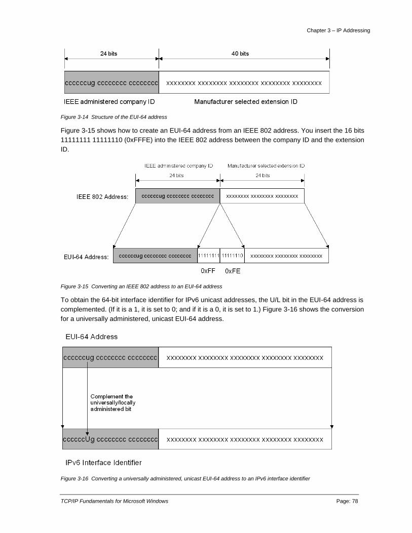
Chapter 3 – IP Addressing
TCP/IP Fundamentals for Microsoft Windows Page: 78
Figure 3-14 Structure of the EUI-64 address
Figure 3-15 shows how to create an EUI-64 address from an IEEE 802 address. You insert the 16 bits
11111111 11111110 (0xFFFE) into the IEEE 802 address between the company ID and the extension
ID.
Figure 3-15 Converting an IEEE 802 address to an EUI-64 address
To obtain the 64-bit interface identifier for IPv6 unicast addresses, the U/L bit in the EUI-64 address is
complemented. (If it is a 1, it is set to 0; and if it is a 0, it is set to 1.) Figure 3-16 shows the conversion
for a universally administered, unicast EUI-64 address.
Figure 3-16 Converting a universally administered, unicast EUI-64 address to an IPv6 interface identifier

Chapter 3 – IP Addressing
TCP/IP Fundamentals for Microsoft Windows Page: 79
To obtain an IPv6 interface identifier from an IEEE 802 address, you must first map the IEEE 802
address to an EUI-64 address, and then you complement the U/L bit. Figure 3-17 shows this
conversion for a universally administered, unicast IEEE 802 address.
Figure 3-17 Converting a universally administered, unicast IEEE 802 address to an IPv6 interface identifier
IEEE 802 Address Conversion Example
Host A has the Ethernet MAC address of 00-AA-00-3F-2A-1C. First, you convert it to EUI-64 format by
inserting FF-FE between the third and fourth bytes, yielding 00-AA-00-FF-FE-3F-2A-1C. Then you
complement the U/L bit, which is the seventh bit in the first byte. The first byte in binary form is
00000000. When you complement the seventh bit, it becomes 00000010 (0x02). When you convert the
final result, 02-AA-00-FF-FE-3F-2A-1C, to colon hexadecimal notation, it becomes the interface
identifier 2AA:FF:FE3F:2A1C. As a result, the link-local address that corresponds to the network
adapter with the MAC address of 00-AA-00-3F-2A-1C is FE80::2AA:FF:FE3F:2A1C.
When you complement the U/L bit, add 0x2 to the first byte if the address is universally administered,
and subtract 0x2 from the first byte if the address is locally administered.
Temporary Address Interface Identifiers
In today’s IPv4-based Internet, a typical Internet user connects to an Internet service provider (ISP) and
obtains an IPv4 address using the Point-to-Point Protocol (PPP) and the Internet Protocol Control
Protocol (IPCP). Each time the user connects, a different IPv4 address might be obtained, making it
difficult to track a dial-up user’s traffic on the Internet on the basis of an IPv4 address.
For IPv6-based dial-up connections, the user is assigned a 64-bit prefix after the connection is made
through router discovery and stateless address autoconfiguration. If the interface identifier is always
based on the EUI-64 address (as derived from the static IEEE 802 address), an attacker can identify
the traffic of a specific node regardless of the prefix, making it easy to track specific users and how they

Chapter 3 – IP Addressing
TCP/IP Fundamentals for Microsoft Windows Page: 80
use the Internet. To address this concern and provide a level of anonymity, RFC 4941 describes an
alternative IPv6 interface identifier that is randomly generated and changes over time.
The initial interface identifier is generated by using random numbers. For IPv6 systems that cannot
store any historical information for generating future interface identifier values, a new random interface
identifier is generated each time the IPv6 protocol is initialized. For IPv6 systems that have storage
capabilities, a history value is stored and, when the IPv6 protocol is initialized, a different interface
identifier is created through the following process:
1. Retrieve the history value from storage, and append the interface identifier based on the EUI-64
address of the adapter.
2. Compute the Message Digest-5 (MD5) hash algorithm over the quantity in step 1. A hash produces a
fixed size mathematical result from an input. Hashes are easy to compute, but it is computationally
difficult to determine the input from the hash result.
3. Save the last 64 bits of the MD5 hash computed in step 2 as the history value for the next interface
identifier computation.
4. Take the first 64 bits of the MD5 hash computed in Step 2, and set the seventh bit to 0. The seventh
bit corresponds to the U/L bit, which, when set to 0, indicates a locally administered IPv6 interface
identifier. The result is the IPv6 interface identifier.
The resulting IPv6 address, based on this random interface identifier, is known as a temporary address.
Temporary addresses are generated for public address prefixes that use stateless address
autoconfiguration.
IPv6 Multicast Addresses
IPv6 multicast addresses have the first eight bits fixed at 1111 1111. Therefore the address prefix for all
IPv6 multicast addresses is FF00::/8. Beyond the first eight bits, multicast addresses include additional
structure to identify flags, their scope, and the multicast group. Figure 3-18 shows the structure of the
IPv6 multicast address.
Figure 3-18 The structure of the IPv6 multicast address
The fields in the multicast address are:
Flags
Indicates flags set on the multicast address. The size of this field is 4 bits. RFC 4291defines the
Transient (T) flag, which uses the low-order bit of the Flags field. When set to 0, the T flag indicates
that the multicast address is a permanently assigned (well-known) multicast address allocated by
the IANA. When set to 1, the T flag indicates that the multicast address is a transient (non-
permanently-assigned) multicast address.
Scope

Chapter 3 – IP Addressing
TCP/IP Fundamentals for Microsoft Windows Page: 81
Indicates the scope of the IPv6 network for which the multicast traffic must be delivered. The size of
this field is 4 bits. Routers use the multicast scope and information provided by multicast routing
protocols to determine whether multicast traffic can be forwarded.
RFC 4291 defines the values for the Scope field. The most prevalent values for the Scope field are
1 (interface-local scope), 2 (link-local scope), and 5 (site-local scope).
Group ID
Identifies the multicast group and is unique within the scope. The size of this field is 112 bits.
Permanently assigned group IDs are independent of the scope. Transient group IDs are relevant
only to a specific scope.
To identify all nodes for the interface-local and link-local scopes, the following addresses are defined:
FF01::1 (interface-local scope, all-nodes multicast address)
FF02::1 (link-local scope, all-nodes multicast address)
To identify all routers for the interface-local, link-local, and site-local scopes, the following addresses
are defined:
FF01::2 (interface-local scope, all-routers multicast address)
FF02::2 (link-local scope, all-routers multicast address)
FF05::2 (site-local scope, all-routers multicast address)
For the current list of permanently assigned IPv6 multicast addresses, see
http://www.iana.org/assignments/ipv6-multicast-addresses.
IPv6 multicast addresses replace all forms of IPv4 broadcast addresses. The link-local scope, all-nodes
multicast address (FF02::1) in IPv6 replaces the IPv4 network broadcast address (in which all host bits
are set to 1 in a classful environment), the subnet broadcast address (in which all host bits are set to 1
in a classless environment), and the limited broadcast address (255.255.255.255).
For more information about IPv6 multicast addresses and processes, see Appendix A, "IP Multicast."
Solicited-Node Multicast Address
The solicited-node multicast address facilitates the efficient querying of network nodes to resolve a link-
layer address from a known IPv6 address, known as link-layer address resolution. In IPv4, the ARP
Request frame on Ethernet and 802.11 wireless network segments is sent to the broadcast address
0xFF-FF-FF-FF-FF-FF. This frame disturbs all nodes on the network segment, including those that are
not running IPv4. IPv6 uses the Neighbor Solicitation message to perform link-layer address resolution.
However, using the local-link scope, all-nodes multicast address as the Neighbor Solicitation message
destination would disturb all IPv6 nodes on the local link, so the solicited-node multicast address is
used. The solicited-node multicast address is constructed from the prefix FF02::1:FF00:0/104 and the
last 24 bits of a unicast IPv6 address. Figure 3-19 shows the mapping of a unicast IPv6 address to its
corresponding solicited-node multicast address.

Chapter 3 – IP Addressing
TCP/IP Fundamentals for Microsoft Windows Page: 82
Figure 3-19 Creating the solicited-node multicast address
For example, Node A is assigned the link-local address of FE80::2AA:FF:FE28:9C5A and is also
listening on the corresponding solicited-node multicast address of FF02::1:FF28:9C5A. (The underlines
highlight the correspondence of the last six hexadecimal digits.) Node B on the local link must resolve
Node A’s link-local address FE80::2AA:FF:FE28:9C5A to its corresponding link-layer address. Node B
sends a Neighbor Solicitation message to the solicited-node multicast address of FF02::1:FF28:9C5A.
Because Node A is listening on this multicast address, it processes the Neighbor Solicitation message
and replies with a unicast Neighbor Advertisement message, completing the address resolution
process.
By using the solicited-node multicast address, link-layer address resolution, a common occurrence on a
link, does not disturb all network nodes. As a result, very few nodes are disturbed during address
resolution. In practice, the relationship between the link-layer address, the IPv6 interface ID, and the
solicited-node address allows the solicited-node address to act as a pseudo-unicast address for very
efficient address resolution.
IPv6 Anycast Addresses
An anycast address is assigned to multiple interfaces. The routing structure forwards packets
addressed to an anycast address so that they reach the nearest interface to which the anycast address
is assigned. To facilitate delivery, the routing infrastructure must be aware of the interfaces assigned
anycast addresses and their “distance” in terms of routing metrics. At present, anycast addresses are
used as destination addresses only. Anycast addresses are assigned out of the unicast address space,
and their scope matches that of the type of unicast address from which the anycast address is
assigned.
The Subnet-Router anycast address is created from the subnet prefix for a given interface. To construct
the Subnet-Router anycast address, you fix the bits in the 64-bit subnet prefix at their appropriate
values, and you set to 0 the bits in the Interface ID portion of the address. All router interfaces attached
to a subnet are assigned the Subnet-Router anycast address for that subnet. The Subnet-Router
anycast address can be used to communicate with one of multiple routers attached to a remote subnet,
for example, to obtain network management statistics for traffic on the subnet.
IPv6 Addresses for a Host
An IPv4 host with a single network adapter typically has a single IPv4 address assigned to that adapter.
An IPv6 host, however, usually has multiple IPv6 addresses—even with a single interface. An IPv6 host
is assigned the following unicast addresses:
A link-local address for each interface.

Chapter 3 – IP Addressing
TCP/IP Fundamentals for Microsoft Windows Page: 83
Unicast addresses for each interface (which could be a site-local address and one or multiple global
unicast addresses).
The loopback address (::1) for the loopback interface.
IPv6 hosts typically have at least two addresses with which they can receive packets—a link-local
address for local link traffic and a routable site-local or global address.
Additionally, each host listens for traffic on the following multicast addresses:
The interface-local scope, all-nodes multicast address (FF01::1).
The link-local scope, all-nodes multicast address (FF02::1).
The solicited-node address for each unicast address on each interface.
The multicast addresses of joined groups on each interface.
IPv6 Addresses for a Router
An IPv6 router is assigned the following unicast and anycast addresses:
A link-local address for each interface.
Unicast addresses for each interface (which could be a site-local address and one or multiple global
unicast addresses).
A Subnet-Router anycast address.
Additional anycast addresses (optional).
The loopback address (::1) for the loopback interface.
Additionally, each router listens for traffic on the following multicast addresses:
The interface-local scope, all-nodes multicast address (FF01::1).
The interface-local scope, all-routers multicast address (FF01::2).
The link-local scope, all-nodes multicast address (FF02::1).
The link-local scope, all-routers multicast address (FF02::2).
The site-local scope, all-routers multicast address (FF05::2).
The solicited-node address for each unicast address on each interface.
The multicast addresses of joined groups on each interface.

Chapter 3 – IP Addressing
TCP/IP Fundamentals for Microsoft Windows Page: 84
Comparing IPv4 and IPv6 Addressing
Table 3-5 lists IPv4 addresses and addressing concepts and their IPv6 equivalents.
IPv4 Address IPv6 Address
Internet address classes Not applicable in IPv6
IPv4 multicast addresses (224.0.0.0/4) IPv6 multicast addresses (FF00::/8)
Broadcast addresses: network broadcast, subnet
broadcast, all-subnets directed broadcast, limited
broadcast
Not applicable in IPv6
Unspecified address is 0.0.0.0 Unspecified address is ::
Loopback address is 127.0.0.1 Loopback address is ::1
Public IPv4 addresses Global unicast addresses
Private IPv4 addresses (10.0.0.0/8, 172.16.0.0/12, and
192.168.0.0/16)
Site-local addresses (FEC0::/10)
APIPA addresses (169.254.0.0/16) Link-local addresses (FE80::/64)
Address syntax: dotted decimal notation Address syntax: colon hexadecimal format with
suppression of leading zeros and zero compression.
Embedded IPv4 addresses are expressed in dotted
decimal notation.
Address prefix syntax: prefix length or dotted decimal
(subnet mask) notation
Address prefix syntax: prefix length notation only
Table 3-5 Comparing IPv4 and IPv6 Addressing
Chapter 3 – IP Addressing
TCP/IP Fundamentals for Microsoft Windows Page: 85
Chapter Summary
The key information in this chapter is the following:
You express IPv4 addresses in dotted decimal format. You express IPv4 address prefixes as a dotted
decimal form of the starting address with the prefix length indicated by either an integer number or a
dotted decimal number, also known as a subnet mask.
IPv4 uses unicast addresses to deliver a packet from one source to one destination, multicast
addresses to deliver a packet from one source to many destinations, and broadcast addresses to
deliver a packet from one source to every destination on the subnet.
For IPv4, you can use public unicast addresses (if assigned by ICANN or an ISP) or private addresses
(10.0.0.0/8, 172.16.0.0/12, or 192.168.0.0/16). The TCP/IP components of Windows use APIPA
addresses to automatically configure hosts with addresses from the 169.254.0.0/16 address prefix on a
single subnet.
You express IPv6 addresses in colon hexadecimal format, suppressing leading zeros and compressing
a single set of contiguous blocks of zeros using double colon notation. You express IPv6 address
prefixes as a colon hexadecimal form of the starting address with a prefix length.
IPv6 uses unicast addresses, multicast addresses, and anycast addresses to deliver a packet from one
source to one of many destinations.
For unicast IPv6 addresses, you can use global addresses (if they are assigned by IANA or an ISP),
site-local addresses (FEC0::/10), or link-local addresses (FE80::/64). Link-local addresses require you
to specify a zone ID to identify the link for a destination. Site-local addresses require you to specify a
zone ID to identify the site for a destination if you are using multiple sites.
You typically derive IPv6 interface identifiers from IEEE 802 addresses or IEEE EUI-64 addresses.
The solicited-node multicast address is a special multicast address used for efficient link-layer address
resolution on a subnet.
Chapter 3 – IP Addressing
TCP/IP Fundamentals for Microsoft Windows Page: 86
Chapter Glossary
address – An identifier that is assigned at the Internet layer to an interface or a set of interfaces and
that identifies the source or destination of IP packets.
address class – A predefined grouping of IPv4 addresses used on the Internet. Addresses classes
defined networks of specific sizes and determined the range of numbers that can be assigned for the
first octet in the IPv4 address. Classless Inter-Domain Routing (CIDR) has made classful IPv4
addressing obsolete.
address prefix – An address range that is defined by setting high-order fixed bits to defined values and
low-order variable bits to 0. Address prefixes are routinely used to express a range of allowable
addresses, subnet prefixes assigned to subnets, and routes. In IPv4, you express address prefixes in
prefix length or dotted decimal (subnet mask) notation. In IPv6, you express address prefixes in prefix
length notation.
anycast address – An address that is assigned from the unicast address space, identifies multiple
interfaces, and is used to deliver packets from one source to one of many destinations. With the
appropriate routing topology, packets addressed to an anycast address are delivered to the nearest
interface that has the address assigned.
APIPA – See Automatic Private IP Addressing (APIPA).
Automatic Private IP Addressing (APIPA) – A feature of the TCP/IP component in Windows
Server 2003 and Windows XP. APIPA enables a computer to autoconfigure an IPv4 address and
subnet mask from the range 169.254.0.0/16 when the TCP/IP component is configured for automatic
configuration and no DHCP server is available.
CIDR – See Classless Inter-Domain Routing (CIDR).
Class A IPv4 address – A unicast IPv4 address that ranges from 1.0.0.1 through 127.255.255.254. The
first octet indicates the address prefix, and the last three octets indicate the host ID. Classless Inter-
Domain Routing (CIDR) made classful IPv4 addressing obsolete.
Class B IPv4 address – A unicast IPv4 address that ranges from 128.0.0.1 through 191.255.255.254.
The first two octets indicate the address prefix, and the last two octets indicate the host ID. Classless
Inter-Domain Routing (CIDR) made classful IPv4 addressing obsolete.
Class C IPv4 address – A unicast IPv4 address that ranges from 192.0.0.1 to 223.255.255.254. The
first three octets indicate the address prefix, and the last octet indicates the host ID. Classless Inter-
Domain Routing (CIDR) made classful IPv4 addressing obsolete.
Classless Inter-Domain Routing (CIDR) – A technique for aggregating routes and assigning IPv4
addresses on the modern-day Internet. CIDR expresses address prefixes in the form of an address
prefix and a prefix length, rather than in terms of the address classes that CIDR replaces.
colon hexadecimal notation – The notation used to express IPv6 addresses. The 128-bit IPv6 address
is divided into eight 16-bit blocks. Each block is expressed as a hexadecimal number, and adjacent
blocks are separated by colons. Within each block, leading zeros are suppressed. An example of an
IPv6 unicast address in colon hexadecimal notation is 2001:DB8:2A1D:48C:2AA:3CFF:FE21:81F9.

Chapter 3 – IP Addressing
TCP/IP Fundamentals for Microsoft Windows Page: 87
dotted decimal notation – The notation most commonly used to express IPv4 addresses. The 32-bit
IPv4 address is divided into four 8-bit blocks. Each block is expressed as a decimal number, and
adjacent blocks are separated by periods. An example of an IPv4 unicast address in dotted decimal
notation is 131.107.199.45.
double colon – The practice of compressing a single contiguous series of zero blocks of an IPv6
address to “::”. For example, the multicast address FF02:0:0:0:0:0:0:2 is expressed as FF02::2.
EUI – See Extended Unique Identifier.
EUI-64 address – A 64-bit link-layer address that is used as a basis for an IPv6 interface identifier.
Extended Unique Identifier – A link-layer address defined by the Institute of Electrical and Electronics
Engineers (IEEE).
global unicast address – An IPv6 unicast address that is globally routable and reachable on the IPv6
portion of the Internet. IPv6 global addresses are equivalent to public IPv4 addresses.
IEEE – Institute of Electrical and Electronics Engineers.
IEEE 802 address – A 48-bit link-layer address defined by the IEEE. Ethernet and Token Ring network
adapters use IEEE 802 addresses.
IEEE EUI-64 address – See EUI-64 address.
illegal address – A duplicate address that conflicts with a public IPv4 address that the ICANN has
already assigned to another organization.
link-local address – A local-use address with the prefix of FE80::/64 and whose scope is the local link.
Nodes use link-local addresses to communicate with neighboring nodes on the same link. Link-local
addresses are equivalent to Automatic Private IP Addressing (APIPA) IPv4 addresses.
loopback address – For IPv4, the address 127.0.0.1. For IPv6, the address 0:0:0:0:0:0:0:1 (or ::1).
Nodes use the loopback address to send packets to themselves.
multicast address – An address that identifies zero or multiple interfaces and is used to deliver packets
from one source to many destinations. With the appropriate multicast routing topology, packets
addressed to a multicast address are delivered to all interfaces identified by the address.
prefix length notation – The practice of expressing address prefixes as StartingAddress/PrefixLength, in
which PrefixLength is the number of high-order bits in the address that are fixed.
private addresses – IPv4 addresses that organizations use for private intranet addressing within one of
the following address prefixes: 10.0.0.0/8, 172.16.0.0/12, 192.168.0.0/16.
public addresses – IPv4 addresses that are assigned by the ICANN and that are guaranteed to be
globally unique and reachable on the IPv4 Internet.
site-local address – A local-use IPv6 address identified by the prefix FEC0::/10. The scope of a site-
local address is a site. Site-local addresses are equivalent to the IPv4 private address space. Site-local
addresses are not reachable from other sites, and routers must not forward site-local traffic outside the
site.
solicited-node multicast address – An IPv6 multicast address that nodes use to resolve addresses. The
solicited-node multicast address is constructed from the prefix FF02::1:FF00:0/104 and the last 24 bits

Chapter 3 – IP Addressing
TCP/IP Fundamentals for Microsoft Windows Page: 88
of a unicast IPv6 address. The solicited-node multicast address acts as a pseudo-unicast address to
efficiently resolve addresses on IPv6 links.
subnet mask – The expression of the length of an address prefix for IPv4 address ranges in dotted
decimal notation. For example, the address prefix 131.107.0.0/16 in subnet mask notation is
131.107.0.0, 255.255.0.0.
unicast address – An address that identifies a single interface and is used for delivering packets from
one source to a single destination. With the appropriate unicast routing topology, packets addressed to
a unicast address are delivered to a single interface.
unspecified address – For IPv4, the address 0.0.0.0. For IPv6, the address 0:0:0:0:0:0:0:0 (or ::). The
unspecified address indicates the absence of an address.
zone ID – An integer that specifies the zone of the destination for IPv6 traffic. In the Ping, Tracert, and
Pathping commands, the syntax for specifying a zone ID is IPv6Address%ZoneID. Typically, the
ZoneID value for link-local addresses is equal to the interface index. For site-local addresses, ZoneID is
equal to the site number. The ZoneID parameter is not needed when the destination is a global address
and when multiple sites are not being used.

Chapter 4 – Subnetting
TCP/IP Fundamentals for Microsoft Windows Page: 89
Chapter 4 – Subnetting
Abstract
This chapter describes the details of subnetting for both IPv4 and IPv6 address prefixes. Network administrators need
to thoroughly understand subnetting techniques for both types of address prefixes to efficiently allocate and administer
the unicast address spaces assigned and used on private intranets. This chapter includes detailed discussions of
different subnetting techniques for IPv4 and IPv6 address prefixes. By using these techniques, you can determine
subnetted address prefixes and, for IPv4, the range of usable IPv4 addresses for each new subnetted address prefix.

Chapter 4 – Subnetting
TCP/IP Fundamentals for Microsoft Windows Page: 90
Chapter Objectives
After completing this chapter, you will be able to:
Determine the subnet prefix of an IPv4 address when expressed in prefix length or subnet mask
notation.
Determine how many IPv4 host ID bits you need to create a particular number of subnets.
Subnet an IPv4 address prefix within an octet and across octet boundaries, enumerating the list of
subnetted address prefixes and the ranges of valid IPv4 addresses for each subnetted address prefix.
Define variable length subnetting and how you can use it to create subnetted address prefixes that
match the number of hosts on a particular subnet.
Subnet a global IPv6 address prefix, enumerating the list of subnetted address prefixes.

Chapter 4 – Subnetting
TCP/IP Fundamentals for Microsoft Windows Page: 91
Subnetting for IPv4
Subnetting is a set of techniques that you can use to efficiently divide the address space of a unicast
address prefix for allocation among the subnets of an organization network. The fixed portion of a
unicast address prefix includes the bits up to and including the prefix length that have a defined value.
The variable portion of a unicast address prefix includes the bits beyond the prefix length that are set to
0. Subnetting is the use of the variable portion of a unicast address prefix to create address prefixes
that are more efficient (that waste fewer possible addresses) for assignment to the subnets of an
organization network.
Subnetting for IPv4 was originally defined to make better use of the host bits for Class A and Class B
IPv4 public address prefixes. Consider the example network in Figure 4-1.
Figure 4-1 Network 157.60.0.0/16 before subnetting
The subnet using the class B address prefix of 157.60.0.0/16 can support up to 65,534 nodes, which is
far too many nodes to have on the same subnet. You want to better use the address space of
157.60.0.0/16 through subnetting. However, subnetting 157.60.0.0/16 should not require the
reconfiguration of the routers of the Internet.
In a simple example of subnetting, you can subnet 157.60.0.0/16 by using the first 8 host bits (the third
octet) for the new subnetted address prefix. If you subnetted 157.60.0.0/16 as shown in Figure 4-2, you
would create separate subnets with their own subnetted address prefixes (157.60.1.0/24,
157.60.2.0/24, 157.60.3.0/24), with up to 254 host IDs on each subnet. The router would become aware
of the separate subnetted address prefixes and route IPv4 packets to the appropriate subnet.
Figure 4-2 Network 157.60.0.0/16 after subnetting
The routers of the Internet would still regard all the nodes on the three subnets as being located on the
address prefix 157.60.0.0/16. The Internet routers would be unaware of the subnetting being done to

Chapter 4 – Subnetting
TCP/IP Fundamentals for Microsoft Windows Page: 92
157.60.0.0/16 and therefore require no reconfiguration. The subnetting of an address prefix is not
visible to the routers outside the network being subnetted.
When you assign IPv4 address prefixes in the form of subnet prefixes to the subnets of your
organization, you should begin with one or more public address prefixes assigned by the Internet
Corporation for Assigned Names and Numbers (ICANN) or an Internet service provider (ISP), the
private address space (10.0.0.0/8, 172.16.0.0/12, and 192.168.0.0/16), or both. The set of starting
address prefixes represent a fixed address space.
You can divide the variable portion of an IPv4 address prefix to represent additional subnets and the
host IDs on each subnet. For example, the IPv4 address prefix 131.107.192.0/18 has 18 fixed bits (as
the prefix length shows) and 14 variable bits (the bits in the host ID portion of the address prefix). You
might determine that your organization needs up to 50 subnets. Therefore, you divide the 14 variable
bits into 6 bits, which you will use to identify subnets (you can express up to 64 subnets with 6 bits) and
8 bits, which you will use to identify up to 254 host IDs on each subnet. The resulting address prefix for
each subnetted address prefix has a 24-bit prefix length (the original 18 bits plus 6 bits used for
subnetting).
Subnetting for IPv4 produces a set of subnetted address prefixes and their corresponding ranges of
valid IPv4 addresses, By assigning subnetted address prefixes that contain an appropriate number of
host IDs to the physical and logical subnets of an organization’s IPv4 network, network administrators
can use the available address space in the most efficient manner possible.
Before you begin IPv4 subnetting, you must determine your organization’s current requirements and
plan for future requirements. Follow these guidelines:
Determine how many subnets your network requires. Subnets include physical or logical subnets to
which hosts connect and possibly private wide area network (WAN) links between sites.
Determine how many host IDs each subnet requires. Each host and router interface running IPv4
requires at least one IPv4 address.
Based on those requirements, you will define a set of subnetted address prefixes with a range of valid
IPv4 addresses for each subnetted address prefix. Your subnets do not all need to have the same
number of hosts; most IPv4 networks include subnets of various sizes.
Although the concept of subnetting by using host ID bits is straightforward, the actual mechanics of
subnetting are a bit more complicated. Subnetting requires a three-step procedure:
1. Determine how many host bits to use for the subnetting.
2. Enumerate the new subnetted address prefixes.
3. Enumerate the range of IPv4 addresses for each new subnetted address prefix.
Determining the Subnet Prefix of an IPv4 Address Configuration
Before you begin the mechanics of IPv4 subnetting, you should be able to determine the subnet prefix
from an arbitrary IPv4 address configuration, which typically consists of an IPv4 address and a prefix
length or an IPv4 address and a subnet mask. The following sections show you how to determine the
subnet prefix for IPv4 address configurations when the prefix length is expressed in prefix length and
dotted decimal (subnet mask) notation.

Chapter 4 – Subnetting
TCP/IP Fundamentals for Microsoft Windows Page: 93
Prefix Length Notation
To determine the subnet prefix from an arbitrary IPv4 address using prefix length notation (w.x.y.z/n),
take the values of the high-order n bits of the address and combine them with 32-n zero bits. Then
convert the resulting 32-bit number to dotted decimal notation.
For example, for the IPv4 address configuration of 192.168.207.47/22, the high-order 22 bits are
11000000 10101000 110011. To obtain the subnet prefix, combine this result with the low-order 10 bits
of 00 00000000. The result is 11000000 10101000 11001100 00000000, or 192.168.204.0/22.
To determine the subnet prefix of an IPv4 address configuration in prefix length notation without having
to work entirely with binary numbers, use the following method:
1. Express the number n (the prefix length) as the sum of 4 numbers by successively subtracting 8 from
n. For example, 20 is 8+8+4+0.
2. Create a table with four columns and three rows. In the first row, place the decimal octets of the IPv4
address. In the second row, place the four digits of the sum you determined in step 1.
3. For the columns that have 8 in the second row, copy the octet from the first row to the third row. For
the columns that have 0 in the second row, place a 0 in the third row.
4. For the columns that have a number between 8 and 0 in the second row, convert the decimal number
in the first row to binary, take the high-order bits for the number of bits indicated in the second row, fill
the rest of the bits with zero, and then convert to a decimal number.
For example, for the IPv4 address configuration of 192.168.207.47/22, 22 is 8+8+6+0. From this,
construct the following table:
192 168 207 47
8 8 6 0
For the first and second octets, copy the octets from the first row. For the last octet, place a 0 in the
third row. The table becomes:
192 168 207 47
8 8 6 0
192 168 0
For the third octet, convert the number 207 to binary for the first 6 binary digits using the decimal to
binary conversion method described in Chapter 3, "IP Addressing." The decimal number 207 is
128+64+8+4+2+1, which is 11001111. Taking the first 6 digits 110011 and filling in the octet with 00
produces 11001100, or 204 in decimal. The table becomes:
192 168 207 47
8 8 6 0
192 168 204 0
Therefore, the subnet prefix for the IPv4 address configuration 192.168.207.47/22 is 192.168.204.0/22.

Chapter 4 – Subnetting
TCP/IP Fundamentals for Microsoft Windows Page: 94
Subnet Mask Notation
To extract the subnet prefix from an arbitrary IPv4 address configuration using an arbitrary subnet
mask, IPv4 uses a mathematical operation called a logical AND comparison. In an AND comparison,
the result of two items being compared is true only when both items being compared are true;
otherwise, the result is false. Table 4-1 shows the result of the AND operation for the four possible bit
combinations.
Bit Combination Result
1 AND 1 1
1 AND 0 0
0 AND 0 0
0 AND 1 0
Table 4-1 Result of AND Operation
Therefore, the result of the AND operation is 1 only when both bits being ANDed are 1. Otherwise, the
result is 0.
IPv4 performs a logical AND comparison with the 32-bit IPv4 address and the 32-bit subnet mask. This
operation is known as a bit-wise logical AND. The result of the bit-wise logical AND of the IPv4 address
and the subnet mask is the subnet prefix.
For example, to determine the subnet prefix of the IPv4 address configuration 131.107.189.41 with a
subnet mask of 255.255.240.0, turn both numbers into their binary equivalents, and line them up. Then
perform the AND operation on each bit, and write down the result.
IPv4 Address: 10000011 01101011 10111101 00101001
Subnet Mask: 11111111 11111111 11110000 00000000
Subnet Prefix: 10000011 01101011 10110000 00000000
The result of the bit-wise logical AND of the 32 bits of the IPv4 address and the subnet mask is the
subnet prefix 131.107.176.0, 255.255.240.0. The behavior of the bit-wise logical AND operation
between the IPv4 address and the subnet mask is the following:
For the bits in the fixed portion of the address (in which the bits in the subnet mask are set to 1), the
subnet prefix bits are copied from the IPv4 address, essentially extracting the subnet prefix of the IPv4
address.
For the bits in the variable portion of the address (in which the bits in the subnet mask are set to 0), the
subnet prefix bits are set to 0, essentially discarding the host ID portion of the IPv4 address.
To summarize, the bit-wise logical AND extracts the subnet prefix portion and discards the host ID
portion of an IPv4 address. The result is the subnet prefix.
To determine the subnet prefix of an IPv4 address configuration in subnet mask notation without having
to work entirely with binary numbers, use the following method:
1. Create a table with four columns and three rows. In the first row, place the decimal octets of the IPv4
address. In the second row, place the decimal octets of the subnet mask.
2. For the columns that have 255 in the second row, copy the octet from the first row to the third row.

Chapter 4 – Subnetting
TCP/IP Fundamentals for Microsoft Windows Page: 95
For the columns that have 0 in the second row, place a 0 in the third row.
3. For the columns that have a number between 255 and 0 in the second row, AND the decimal
numbers in the first two rows. You can do this by converting both numbers to binary, performing the
AND comparison for all 8 bits in the octet, and then converting the result back to decimal. Alternately,
you can use a calculator, such as the Windows Calculator, in scientific mode.
For example, for the IPv4 address configuration of 131.107.189.41, 255.255.240.0, construct the
following table:
131 107 189 41
255 255 240 0
For the first and second octets, copy the octets from the first row. For the last octet, place a 0 in the
third row. The table becomes:
131 107 189 41
255 255 240 0
131 107 0
For the third octet, compute 189 AND 240. In binary, this operation becomes:
10111101
AND 11110000
10110000
Converting 10110000 to decimal is 176. Alternately, use the Windows Calculator to compute 189 AND
240, which yields 176.
The table becomes:
131 107 189 41
255 255 240 0
131 107 176 0
Therefore, the subnet prefix for the IPv4 address configuration 131.107.189.41, 255.255.240.0 is
131.107.176.0, 255.255.240.0.
Defining a Prefix Length
The number of variable bits in the subnet prefix determines the maximum number of subnets and hosts
on each subnet that you can have.
Before you define a new prefix length based on your subnetting scheme, you should have a good idea
of the number of subnets and hosts you will have in the future. If you use more variable bits for the new
prefix length than required, you will save the time and administrative difficulty of renumbering your IPv4
network later.

Chapter 4 – Subnetting
TCP/IP Fundamentals for Microsoft Windows Page: 96
The more variable bits that you use, the more subnets you can have—but with fewer hosts on each
subnet. If you make the prefix too long, it will allow for growth in the number of subnets, but it will limit
the growth in the number of hosts on each subnet. If you make the prefix too short, it will allow for
growth in the number of hosts on each subnet, but it will limit the growth in the number of subnets.
Figure 4-3 shows an example of subnetting the third octet.
Figure 4-3 Tradeoff between number of subnets and number of hosts per subnet
Follow these guidelines to determine the number of bits to use for a new prefix length when subnetting:
1. Determine how many subnets you need now and will need in the future.
2. Use additional bits for subnetting if:
You will never require as many hosts per subnet as allowed by the remaining bits.
The number of subnets will increase, requiring additional bits from the host ID.
Defining a new prefix length depends on how many subnets you need. Table 4-2 shows how many
subnets you can create by using a particular number of variable bits (up to 16) to specify each subnet.

Chapter 4 – Subnetting
TCP/IP Fundamentals for Microsoft Windows Page: 97
Number of Subnets Number of Host Bits
1-2 1
3-4 2
5-8 3
9-16 4
17-32 5
33-64 6
65-128 7
129-256 8
257-512 9
513-1,024 10
1,025-2,048 11
2,049-4,096 12
4,097-8,192 13
8,193-16,384 14
16,385-32,768 15
32,769-65,536 16
Table 4-2 Number of Required Subnets and Host Bits
The maximum prefix length for unicast IPv4 addresses is 30. With 30 bits for the subnet prefix, the two
remaining bits can express up to 4 possible combinations. However, the all-zeros and all-ones host IDs
are reserved. Therefore, with two host ID bits, you can express only two usable host IDs (the 01 and 10
combinations).
To determine the maximum number of hosts per subnet for any subnetting scheme:
1. Determine m, the number of bits that remain for the host ID, by subtracting the subnetted prefix
length from 32.
2. Calculate the maximum number of hosts per subnet from 2m - 2.
Based on the address prefix you are subnetting and the number of bits that you need for subnetting,
you can determine whether you are subnetting within an octet or subnetting across an octet boundary.
For example, if you start with an 18-bit address prefix and then use 4 bits for subnetting, then you are
subnetting within the third octet. (The subnetted prefix length is 22, which is still within the third octet.)
However, if you start with a 20-bit address prefix and then use 6 bits for subnetting, then you are
subnetting across the third and fourth octets. (The original prefix length is 20, which is within the third
octet, and the subnetted prefix length is 26, which is within the fourth octet.)
As the following sections describe, the specific procedures for subnetting within an octet and subnetting
across an octet boundary are very different.
Subnetting Within an Octet
When you subnet within an octet, the subnetting procedure has two main steps:

Chapter 4 – Subnetting
TCP/IP Fundamentals for Microsoft Windows Page: 98
Defining the subnetted address prefixes
Defining the range of usable IPv4 addresses for each subnetted address prefix
The following sections describe these steps.
Defining the Subnetted Address Prefixes
You can use two methods to define the set of subnetted address prefixes:
Binary
Decimal
To create an enumerated list of subnetted address prefixes by using binary, perform the following
steps:
1. Based on n, the number of bits chosen for subnetting, create a three-column table with 2n rows. The
first column contains the subnet numbers (starting with 1), the second column contains binary
representations of the subnetted address prefixes, and the third column contains dotted decimal
representations of the subnetted address prefixes.
For each binary representation, the bits corresponding to the address prefix being subnetted are
fixed at their original values, and all host bits are always set to 0. Only the subnet bits vary as you set
them to each possible binary value.
2. In the first row, set the subnet bits to all 0s, and convert the entire subnetted address prefix to dotted
decimal notation. The result is the original address prefix with its new prefix length.
3. In the next row, increment the value within the subnet bits.
4. Convert the binary result to dotted decimal notation.
5. Repeat steps 3 and 4 until you complete the table.
For example, you can perform a 3-bit subnetting of the private address prefix 192.168.0.0/16. The
subnet mask for the new subnetted address prefixes is 255.255.224.0 or /19. Based on n = 3, construct
a table with 8 (= 23) rows, as Table 4-3 shows. In the row for subnet 1, set all subnet bits (those
underlined in the table) to 0, and increment them in each subsequent row.
Subnet Binary Representation Subnetted Address Prefix
1 11000000.10101000.00000000.00000000 192.168.0.0/19
2 11000000.10101000.00100000.00000000 192.168.32.0/19
3 11000000.10101000.01000000.00000000 192.168.64.0/19
4 11000000.10101000.01100000.00000000 192.168.96.0/19
5 11000000.10101000.10000000.00000000 192.168.128.0/19
6 11000000.10101000.10100000.00000000 192.168.160.0/19
7 11000000.10101000.11000000.00000000 192.168.192.0/19
8 11000000.10101000.11100000.00000000 192.168.224.0/19
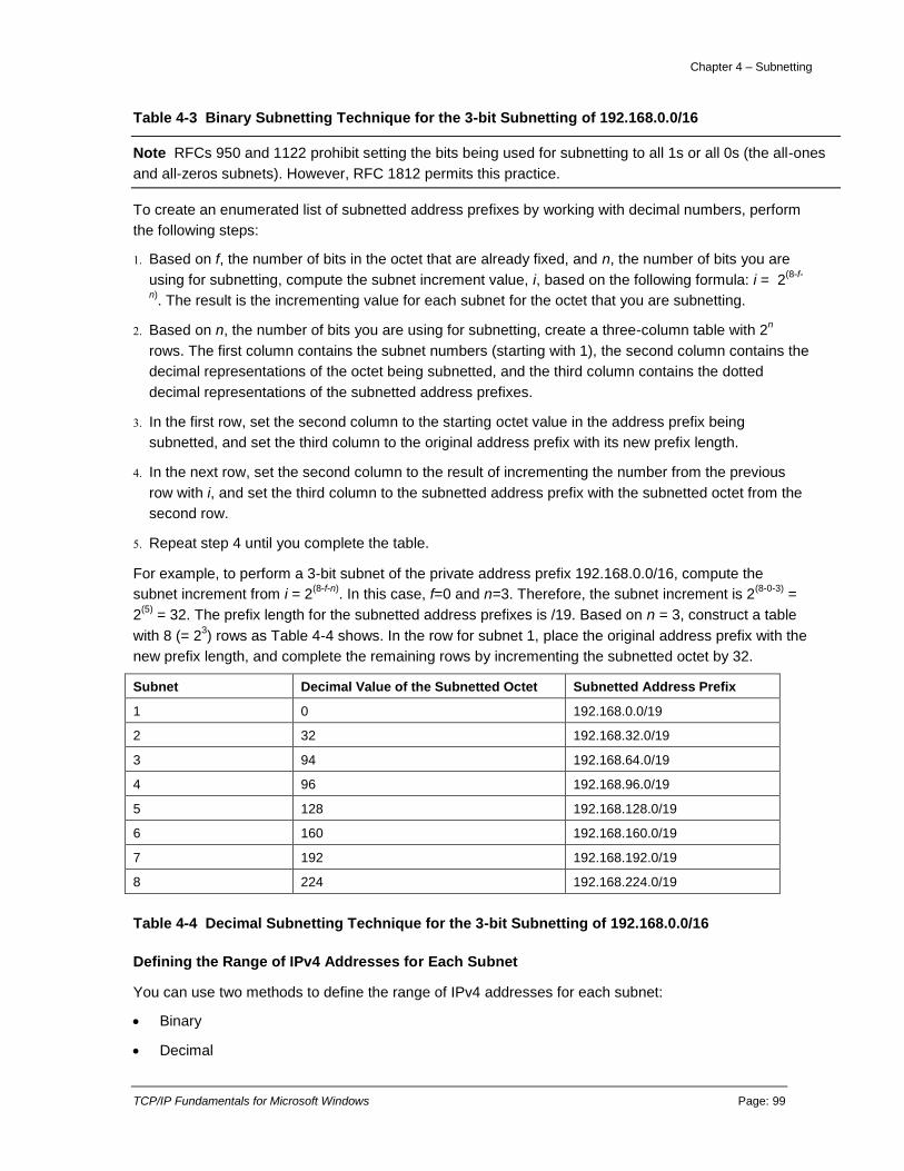
Chapter 4 – Subnetting
TCP/IP Fundamentals for Microsoft Windows Page: 99
Table 4-3 Binary Subnetting Technique for the 3-bit Subnetting of 192.168.0.0/16
Note RFCs 950 and 1122 prohibit setting the bits being used for subnetting to all 1s or all 0s (the all-ones
and all-zeros subnets). However, RFC 1812 permits this practice.
To create an enumerated list of subnetted address prefixes by working with decimal numbers, perform
the following steps:
1. Based on f, the number of bits in the octet that are already fixed, and n, the number of bits you are
using for subnetting, compute the subnet increment value, i, based on the following formula: i = 2(8-f-
n). The result is the incrementing value for each subnet for the octet that you are subnetting.
2. Based on n, the number of bits you are using for subnetting, create a three-column table with 2n
rows. The first column contains the subnet numbers (starting with 1), the second column contains the
decimal representations of the octet being subnetted, and the third column contains the dotted
decimal representations of the subnetted address prefixes.
3. In the first row, set the second column to the starting octet value in the address prefix being
subnetted, and set the third column to the original address prefix with its new prefix length.
4. In the next row, set the second column to the result of incrementing the number from the previous
row with i, and set the third column to the subnetted address prefix with the subnetted octet from the
second row.
5. Repeat step 4 until you complete the table.
For example, to perform a 3-bit subnet of the private address prefix 192.168.0.0/16, compute the
subnet increment from i = 2(8-f-n)
. In this case, f=0 and n=3. Therefore, the subnet increment is 2(8-0-3)
=
2(5)
= 32. The prefix length for the subnetted address prefixes is /19. Based on n = 3, construct a table
with 8 (= 23) rows as Table 4-4 shows. In the row for subnet 1, place the original address prefix with the
new prefix length, and complete the remaining rows by incrementing the subnetted octet by 32.
Subnet Decimal Value of the Subnetted Octet Subnetted Address Prefix
1 0 192.168.0.0/19
2 32 192.168.32.0/19
3 94 192.168.64.0/19
4 96 192.168.96.0/19
5 128 192.168.128.0/19
6 160 192.168.160.0/19
7 192 192.168.192.0/19
8 224 192.168.224.0/19
Table 4-4 Decimal Subnetting Technique for the 3-bit Subnetting of 192.168.0.0/16
Defining the Range of IPv4 Addresses for Each Subnet
You can use two methods to define the range of IPv4 addresses for each subnet:
Binary
Decimal

Chapter 4 – Subnetting
TCP/IP Fundamentals for Microsoft Windows Page: 100
To define the possible host IDs within each subnet, you keep the bits in the subnetted address prefix
fixed while setting the remaining bits (in the host portion of the IPv4 address) to all possible values
except all 1s and all 0s. Recall from Chapter 3, “IP Addressing,” that you should use the following
standard practice when defining the range of valid IPv4 unicast addresses for a given address prefix:
For the first IPv4 unicast address in the range, set all the host bits in the address to 0, except for the
lowest-order bit, which you set to 1.
For the last IPv4 unicast address in the range, set all the host bits in the address to 1, except for the
lowest-order bit, which you set to 0.
The result for each subnetted address prefix is a range of values that describe the possible unicast IPv4
addresses for that subnet.
To define the range of valid IPv4 addresses for a set of subnetted address prefixes using the binary
method, perform the following steps:
1. Based on n, the number of host bits chosen for subnetting, create a three-column table with 2n rows.
The first column contains the subnet numbers (starting with 1), the second column contains the
binary representations of the first and last IPv4 addresses for the subnetted address prefixes, and the
third column contains the dotted decimal representation of the first and last IPv4 addresses of the
subnetted address prefixes. Alternately, add two columns to the previous table used for enumerating
the subnetted address prefixes using the binary technique.
2. In the second column of the first row, the first IPv4 address is the address in which all the host bits
are set to 0 except for the last host bit. The last IPv4 address is the address in which all the host bits
are set to 1 except for the last host bit.
3. In the third column of the first row, convert the binary representation to dotted decimal notation.
4. Repeat steps 2 and 3 for each row until you complete the table.
For example, Table 4-5 shows the range of IPv4 addresses for the 3-bit subnetting of 192.168.0.0/16
with the host bits underlined.

Chapter 4 – Subnetting
TCP/IP Fundamentals for Microsoft Windows Page: 101
Subnet Binary Representation Range of IPv4 Addresses
1 11000000.10101000.00000000.00000001 –
11000000.10101000.00011111.11111110
192.168.0.1 –192.168.31.254
2 11000000.10101000.00100000.00000001 –
11000000.10101000.00111111.11111110
192.168.32.1 –192.168.63.254
3 11000000.10101000.01000000.00000001 –
11000000.10101000.01011111.11111110
192.168.64.1 –192.168.95.254
4 11000000.10101000.01100000.00000001 –
11000000.10101000.01111111.11111110
192.168.96.1 –192.168.127.254
5 11000000.10101000.10000000.00000001 –
11000000.10101000.10011111.11111110
192.168.128.1 –192.168.159.254
6 11000000.10101000.10100000.00000001 –
11000000.10101000.10111111.11111110
192.168.160.1 –192.168.191.254
7 11000000.10101000.11000000.00000001 –
11000000.10101000.11011111.11111110
192.168.192.1 –192.168.223.254
8 11000000.10101000.11100000.00000001 –
11000000.10101000.11111111.11111110
192.168.224.1 –192.168.255.254
Table 4-5 Binary Technique for Defining the Ranges of IPv4 Addresses for the 3-bit Subnetting of
192.168.0.0/16
To define the range of valid IPv4 addresses for a set of subnetted address prefixes using the decimal
method, perform the following steps:
1. Based on n, the number of host bits chosen for subnetting, create a three-column table with 2n rows.
The first column contains the subnet numbers (starting with 1), the second column contains the
dotted decimal representations of the subnetted address prefixes, and the third column contains the
dotted decimal representations of the first and last IPv4 addresses of the subnetted address prefix.
Alternately, add a column to the previous table used for enumerating the subnetted address prefixes
in decimal.
2. For each row, calculate the first IPv4 address in the range by adding 1 to the last octet of the
subnetted address prefix.
3. For each row except the last, calculate the last IPv4 address in the range using the following
formulas:
When you subnet within the first octet, the last value for a given subnet is [NextSubnetID -
1].255.255.254 (in which NextSubnetID is the value of the octet that is being subnetted for the next
subnetted address prefix).
When you subnet within the second octet, the last value for a given subnet is w.[NextSubnetID -
1].255.254.
When you subnet within the third octet, the last value for a given subnet is w.x.[NextSubnetID -
1].254.
When you subnet within the fourth octet, the last value for a given subnet is w.x.y.[NextSubnetID -
2].

Chapter 4 – Subnetting
TCP/IP Fundamentals for Microsoft Windows Page: 102
4. For the last row, calculate the last IPv4 address in the range using the following formulas:
When you subnet within the first octet, the last value is [SubnetID + i - 1].255.255.254 (in which
SubnetID is the value of the octet that is being subnetted for the current subnetted address prefix
and i is the increment value derived when determining the subnetted address prefixes).
When you subnet within the second octet, the last value is w.[SubnetID + i - 1].255.254.
When you subnet within the third octet, the last value is w.x.[SubnetID + i - 1].254.
When you subnet within the fourth octet, the last value is w.x.y.[SubnetID + i - 2].
For example, Table 4-6 shows the range of IPv4 addresses for the 3-bit subnetting of 192.168.0.0/16.
Subnet Subnetted address prefix Range of IPv4 Addresses
1 192.168.0.0/19 192.168.0.1 –192.168.31.254
2 192.168.32.0/19 192.168.32.1 –192.168.63.254
3 192.168.64.0/19 192.168.64.1 –192.168.95.254
4 192.168.96.0/19 192.168.96.1 –192.168.127.254
5 192.168.128.0/19 192.168.128.1 –192.168.159.254
6 192.168.160.0/19 192.168.160.1 –192.168.191.254
7 192.168.192.0/19 192.168.192.1 –192.168.223.254
8 192.168.224.0/19 192.168.224.1 –192.168.255.254
Table 4-6 Decimal Technique for Defining the Ranges of IPv4 Addresses for the 3-bit Subnetting of
192.168.0.0/16
Subnetting Across an Octet Boundary
Like the procedure for subnetting within an octet, the procedure for subnetting across an octet boundary
has two steps:
Defining the subnetted address prefixes
Defining the range of usable IPv4 addresses for each subnetted address prefix
The following sections describe these steps.
Defining the Subnetted address prefixes
To subnet across an octet boundary, do the following:
1. Based on n, the number of host bits you are using for subnetting, create a three-column table with 2n
rows. The first column contains the subnet numbers (starting with 1), the second column contains
representations of the 32-bit subnetted address prefixes as single decimal numbers, and the third
column contains the dotted decimal representations of the subnetted address prefixes.
2. Convert the address prefix (w.x.y.z) being subnetted from dotted decimal notation to N, a decimal
representation of the 32-bit address prefix, using the following formula:
N = w16777216 + x65536 + y256 + z
3. Compute the increment value I using I = 2h where h is the number of host bits remaining.

Chapter 4 – Subnetting
TCP/IP Fundamentals for Microsoft Windows Page: 103
4. In the first row, place N, the decimal representation of the subnetted address prefix, in the second
column, and place the subnetted address prefix w.x.y.z with its new prefix length in the third column.
5. In the next row, add I to the previous row’s decimal representation, and place the result in the second
column.
6. Convert the decimal representation of the subnetted address prefix to dotted decimal notation
(W.X.Y.Z) using the following formula (where s is the decimal representation of the subnetted
address prefix):
W = int(s/16777216)
X = int((s mod(16777216))/65536)
Y = int((s mod(65536))/256)
Z = s mod(256)
int( ) denotes integer division, and mod( ) denotes the modulus (the remainder upon division).
7. Repeat steps 5 and 6 until you complete the table.
For example, to perform a 4-bit subnetting of the address prefix 192.168.180.0/22, construct a table
with 16 (24) rows, as Table 4-7 shows. N, the decimal representation of 192.168.180.0, is 3232281600,
which is the result of 19216777216 + 16865536 + 180256. Because 6 host bits remain, the
increment I is 26 = 64. Additional rows in the table are successive increments of 64.

Chapter 4 – Subnetting
TCP/IP Fundamentals for Microsoft Windows Page: 104
Subnet Decimal Representation Subnetted Address
Prefix
1 3232281600 192.168.180.0/26
2 3232281664 192.168.180.64/26
3 3232281728 192.168.180.128/26
4 3232281792 192.168.180.192/26
5 3232281856 192.168.181.0/26
6 3232281920 192.168.181.64/26
7 3232281984 192.168.181.128/26
8 3232282048 192.168.181.192/26
9 3232282112 192.168.182.0/26
10 3232282176 192.168.182.64/26
11 3232282240 192.168.182.128/26
12 3232282304 192.168.182.192/26
13 3232282368 192.168.183.0/26
14 3232282432 192.168.183.64/26
15 3232282496 192.168.183.128/26
16 3232282560 192.168.183.192/26
Table 4-7 Decimal Subnetting Technique for the 4-bit Subnetting of 192.168.180.0/22
This method is a completely general technique for subnetting, and you can also use it within an octet
and across multiple octets.
Defining the Range of IPv4 Addresses for Each Subnet
To determine the range of usable host IDs for each subnetted address prefix, perform the following
steps:
1. Based on n, the number of host bits you are using for subnetting, create a three-column table with 2n
rows. The first column contains the subnet numbers (starting with 1), the second column contains the
decimal representation of the first and last IPv4 addresses for the subnetted address prefixes, and
the third column contains the dotted decimal representation of the first and last IPv4 addresses of the
subnetted address prefixes. Alternately, add two columns to the previous table used for enumerating
the subnetted address prefixes using the decimal subnetting technique.
2. Compute the increment value J based on h, the number of host bits remaining:
J = 2h – 2
3. The first IPv4 address is N + 1, in which N is the decimal representation of the subnetted address
prefix. The last IPv4 address is N + J.
4. Convert the decimal representation of the first and last IPv4 addresses to dotted decimal notation
(W.X.Y.Z) using the following formula (where s is the decimal representation of the first or last IPv4
address):

Chapter 4 – Subnetting
TCP/IP Fundamentals for Microsoft Windows Page: 105
W = int(s/16777216)
X = int((s mod(16777216))/65536)
Y = int((s mod(65536))/256)
Z = s mod(256)
int( ) denotes integer division, and mod( ) denotes the modulus (the remainder upon division).
5. Repeat steps 3 and 4 for each row of the table.
For example, Table 4-8 shows the range of IPv4 addresses for the 4-bit subnetting of
192.168.180.0/22. The increment J is 26 – 2 = 62.
Subnet Decimal Representation Range of IPv4 Addresses
1 3232281601-3232281662 192.168.180.1-192.168.180.62
2 3232281665-3232281726 192.168.180.65-192.168.180.126
3 3232281729-3232281790 192.168.180.129-192.168.180.190
4 3232281793-3232281854 192.168.180.193-192.168.180.254
5 3232281857-3232281918 192.168.181.1-192.168.181.62
6 3232281921-3232281982 192.168.181.65-192.168.181.126
7 3232281985-3232282046 192.168.181.129-192.168.181.190
8 3232282049-3232282110 192.168.181.193-192.168.181.254
9 3232282113-3232282174 192.168.182.1-192.168.182.62
10 3232282177-3232282238 192.168.182.65-192.168.182.126
11 3232282241-3232282302 192.168.182.129-192.168.182.190
12 3232282305-3232282366 192.168.182.193-192.168.182.254
13 3232282369-3232282430 192.168.183.1-192.168.183.62
14 3232282433-3232282494 192.168.183.65-192.168.183.126
15 3232282497-3232282558 192.168.183.129-192.168.183.190
16 3232282561-3232282622 192.168.183.193-192.168.183.254
Table 4-8 Decimal Enumeration of the Ranges of IPv4 Addresses for the 4-bit Subnetting of
192.168.180.0/22
Variable Length Subnetting
One of the original uses for subnetting was to subdivide a class-based address prefix into a series of
equal-sized subnets. For example, a 4-bit subnetting of a class B address prefix produces 16 equal-
sized subnets. However, subnetting is a general method of using host bits to express subnets and does
not require equal-sized subnets.
Subnets of different sizes can exist within a class-based or classless address prefix. This practice is
well suited to real-world environments, where networks of an organization contain different numbers of
hosts, and you need different-sized subnets to avoid wasting IPv4 addresses. The practice of creating
and deploying various-sized subnets from an IPv4 address prefix is known as variable length
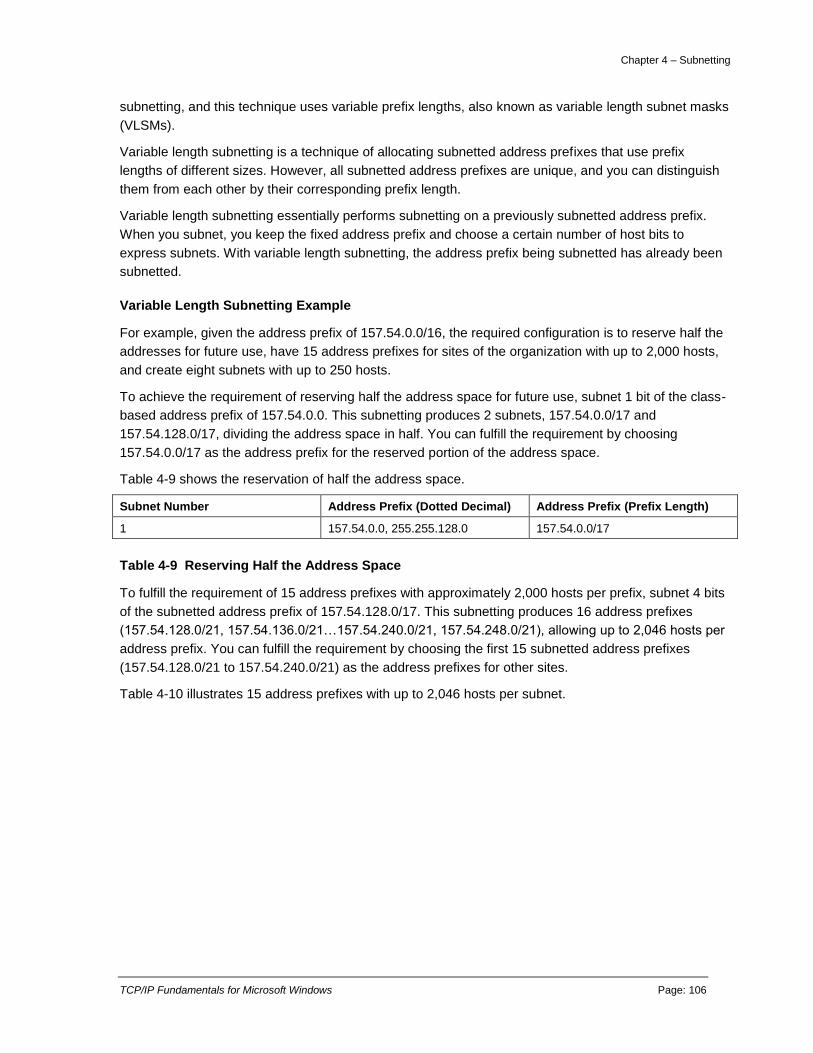
Chapter 4 – Subnetting
TCP/IP Fundamentals for Microsoft Windows Page: 106
subnetting, and this technique uses variable prefix lengths, also known as variable length subnet masks
(VLSMs).
Variable length subnetting is a technique of allocating subnetted address prefixes that use prefix
lengths of different sizes. However, all subnetted address prefixes are unique, and you can distinguish
them from each other by their corresponding prefix length.
Variable length subnetting essentially performs subnetting on a previously subnetted address prefix.
When you subnet, you keep the fixed address prefix and choose a certain number of host bits to
express subnets. With variable length subnetting, the address prefix being subnetted has already been
subnetted.
Variable Length Subnetting Example
For example, given the address prefix of 157.54.0.0/16, the required configuration is to reserve half the
addresses for future use, have 15 address prefixes for sites of the organization with up to 2,000 hosts,
and create eight subnets with up to 250 hosts.
To achieve the requirement of reserving half the address space for future use, subnet 1 bit of the class-
based address prefix of 157.54.0.0. This subnetting produces 2 subnets, 157.54.0.0/17 and
157.54.128.0/17, dividing the address space in half. You can fulfill the requirement by choosing
157.54.0.0/17 as the address prefix for the reserved portion of the address space.
Table 4-9 shows the reservation of half the address space.
Subnet Number Address Prefix (Dotted Decimal) Address Prefix (Prefix Length)
1 157.54.0.0, 255.255.128.0 157.54.0.0/17
Table 4-9 Reserving Half the Address Space
To fulfill the requirement of 15 address prefixes with approximately 2,000 hosts per prefix, subnet 4 bits
of the subnetted address prefix of 157.54.128.0/17. This subnetting produces 16 address prefixes
(157.54.128.0/21, 157.54.136.0/21…157.54.240.0/21, 157.54.248.0/21), allowing up to 2,046 hosts per
address prefix. You can fulfill the requirement by choosing the first 15 subnetted address prefixes
(157.54.128.0/21 to 157.54.240.0/21) as the address prefixes for other sites.
Table 4-10 illustrates 15 address prefixes with up to 2,046 hosts per subnet.

Chapter 4 – Subnetting
TCP/IP Fundamentals for Microsoft Windows Page: 107
Subnet Number Address Prefix (Dotted Decimal) Address Prefix (Prefix Length)
1 157.54.128.0, 255.255.248.0 157.54.128.0/21
2 157.54.136.0, 255.255.248.0 157.54.136.0/21
3 157.54.144.0, 255.255.248.0 157.54.144.0/21
4 157.54.152.0, 255.255.248.0 157.54.152.0/21
5 157.54.160.0, 255.255.248.0 157.54.160.0/21
6 157.54.168.0, 255.255.248.0 157.54.168.0/21
7 157.54.176.0, 255.255.248.0 157.54.176.0/21
8 157.54.184.0, 255.255.248.0 157.54.184.0/21
9 157.54.192.0, 255.255.248.0 157.54.192.0/21
10 157.54.200.0, 255.255.248.0 157.54.200.0/21
11 157.54.208.0, 255.255.248.0 157.54.208.0/21
12 157.54.216.0, 255.255.248.0 157.54.216.0/21
13 157.54.224.0, 255.255.248.0 157.54.224.0/21
14 157.54.232.0, 255.255.248.0 157.54.232.0/21
15 157.54.240.0, 255.255.248.0 157.54.240.0/21
Table 4-10 Fifteen Address Prefixes with up to 2,046 Hosts
To achieve the requirement of eight subnets with up to 250 hosts, subnet 3 bits of the subnetted
address prefix of 157.54.248.0/21. This subnetting produces eight subnets (157.54.248.0/24,
157.54.249.0/24…157.54.254.0/24, 157.54.255.0/24) and allows up to 254 hosts per subnet. You can
fulfill the requirement by choosing all eight subnetted address prefixes (157.54.248.0/24 through
157.54.255.0/24) as the subnet prefixes to assign to individual subnets.
Table 4-11 illustrates eight subnets with 254 hosts per subnet.
Subnet Number Subnet Prefix (Dotted Decimal) Subnet Prefix (Prefix length)
1 157.54.248.0, 255.255.255.0 157.54.248.0/24
2 157.54.249.0, 255.255.255.0 157.54.249.0/24
3 157.54.250.0, 255.255.255.0 157.54.250.0/24
4 157.54.251.0, 255.255.255.0 157.54.251.0/24
5 157.54.252.0, 255.255.255.0 157.54.252.0/24
6 157.54.253.0, 255.255.255.0 157.54.253.0/24
7 157.54.254.0, 255.255.255.0 157.54.254.0/24
8 157.54.255.0, 255.255.255.0 157.54.255.0/24
Table 4-11 Eight Subnets with up to 254 Hosts
Figure 4-4 shows the variable length subnetting of 157.54.0.0/16.
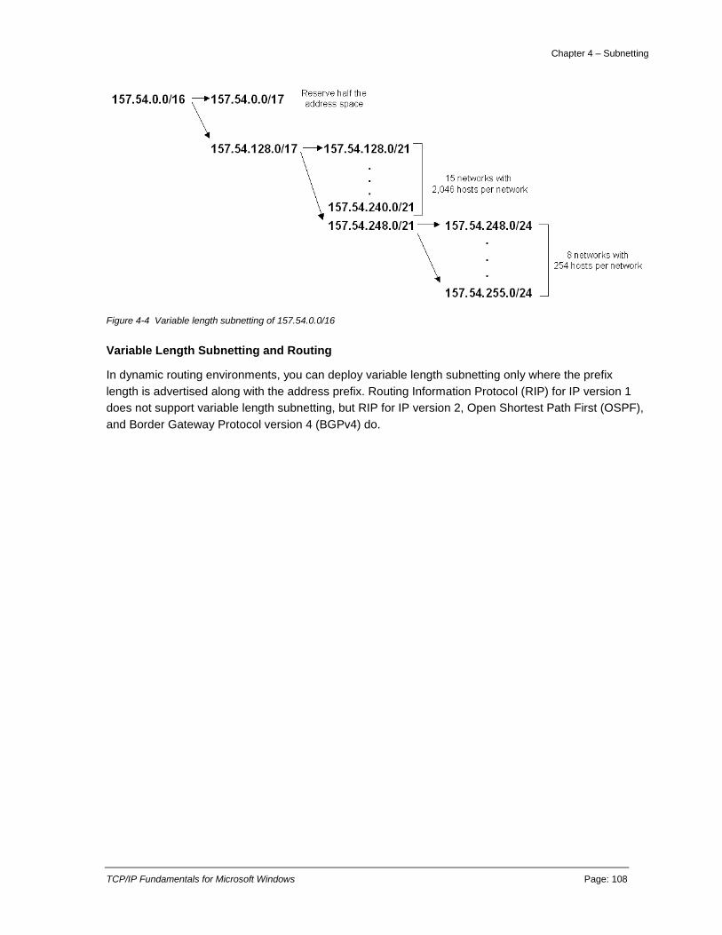
Chapter 4 – Subnetting
TCP/IP Fundamentals for Microsoft Windows Page: 108
Figure 4-4 Variable length subnetting of 157.54.0.0/16
Variable Length Subnetting and Routing
In dynamic routing environments, you can deploy variable length subnetting only where the prefix
length is advertised along with the address prefix. Routing Information Protocol (RIP) for IP version 1
does not support variable length subnetting, but RIP for IP version 2, Open Shortest Path First (OSPF),
and Border Gateway Protocol version 4 (BGPv4) do.

Chapter 4 – Subnetting
TCP/IP Fundamentals for Microsoft Windows Page: 109
Subnetting for IPv6
To subnet the IPv6 address space, you use subnetting techniques to divide the 16-bit Subnet ID field
for a 48-bit global or unique local address prefix in a manner that allows for route summarization and
delegation of the remaining address space to different portions of an IPv6 intranet.
You need not subnet in any specific fashion. The subnetting technique described here assumes that
you subnet by dividing the variable portions of the address space of the Subnet ID field using its high-
order bits. Although this method promotes hierarchical addressing and routing, it is not required. For
example, in a small organization with a small number of subnets, you can also easily create a flat
addressing space for global addresses by numbering the subnets starting from 0.
Subnetting a Global or Unique Local Address Prefix
For global addresses, Internet Assigned Numbers Authority (IANA) or an ISP assigns an IPv6 address
prefix in which the first 48 bits are fixed. For unique local addresses, the first 48 bits are fixed at
FD00::/8 and the random 40-bit global ID assigned to a site of an organization. Subnetting the Subnet
ID field for a 48-bit global or unique local address prefix requires a two-step procedure:
1. Determine the number of bits to be used for the subnetting.
2. Enumerate the new subnetted address prefixes.
Determining the Number of Subnetting Bits
The number of bits that you use for subnetting determines the possible number of new subnetted
address prefixes that you can allocate to portions of your network based on geographical or
departmental divisions. In a hierarchical routing infrastructure, you must determine how many address
prefixes, and therefore how many bits, you need at each level in the hierarchy. The more bits you
choose for the various levels of the hierarchy, the fewer bits you have to enumerate individual subnets
in the last level of the hierarchy.
Depending on the needs of your organization, your subnetting scheme might be along nibble
(hexadecimal digit) or bit boundaries. If you can subnet along nibble boundaries, your subnetting
scheme becomes simplified and each hexadecimal digit can represent a level in the subnetting
hierarchy. For example, a network administrator decides to implement a three-level hierarchy that uses
the first nibble for the site, the next nibble for a building within a site, and the last two nibbles for a
subnet within a building. An example subnet ID for this scheme is 142A, which indicates site 1, building
4, and subnet 42 (0x2A).
In some cases, bit-boundary subnetting is required. For example, a network administrator decides to
implement a two-level hierarchy reflecting a geographical/departmental structure and uses 4 bits for the
geographical level and 6 bits for the departmental level. This means that each department in each
geographical location has only 6 bits of subnetting space left (16 - 6 - 4), or only 64 (= 26) subnets per
department.
On any given level in the hierarchy, a number of bits are already fixed by the previous level in the
hierarchy (f), a number of bits are used for subnetting at the current level in the hierarchy (s), and a
number of bits remain for the next level down in the hierarchy (r). At all times, f+s+r = 16. Figure 4-5
shows this relationship.

Chapter 4 – Subnetting
TCP/IP Fundamentals for Microsoft Windows Page: 110
Figure 4-5 Subnetting the Subnet ID field of a global or unique local IPv6 address prefix
Enumerating Subnetted Address Prefixes
Based on the number of bits used for subnetting, you must list the new subnetted address prefixes, and
you can use the following approaches:
Enumerate new subnetted address prefixes by using binary representations of the subnet ID and
converting to hexadecimal.
Enumerate the new subnetted address prefixes by using hexadecimal representations of the subnet ID
and increment.
Enumerate the new subnetted address prefixes by using decimal representations of the subnet ID and
increment.
Any of these methods produce the same result: an enumerated list of subnetted address prefixes.
In the binary method, the 16-bit subnet ID is expressed as a 16-digit binary number. The bits within the
subnet ID that are being used for subnetting are incremented for all their possible values and for each
value, the 16-digit binary number is converted to hexadecimal and combined with the 48-bit site prefix,
producing the subnetted address prefixes.
To create the enumerated list of subnetted address prefixes using the binary method, perform the
following steps:
1. Based on s (the number of bits chosen for subnetting), m (the prefix length of the address prefix
being subnetted), and f (the number of bits already subnetted), calculate the following:
n = 2s, n is the number of address prefixes that are obtained.
l = 48 + f + s, l is the prefix length of the new subnetted address prefixes.
2. Create a three-column table with n entries. The first column is the address prefix number (starting
with 1), the second column is the binary representation of the subnet ID portion of the new address
prefix, and the third column is the subnetted address prefix (in hexadecimal), which includes the 48-
bit site prefix and the subnet ID.
3. In the first table entry, set all of the bits being used for subnetting to 0. Convert the resulting 16-digit
binary number to hexadecimal, combine with the 48-bit site prefix, and write the subnetted address
prefix. This first subnetted address prefix is just the original address prefix with the new prefix length.

Chapter 4 – Subnetting
TCP/IP Fundamentals for Microsoft Windows Page: 111
4. In the next table entry, increment the value within the subnet bits. Convert the 16-digit binary number
to hexadecimal, combine with the 48-bit site prefix, and write the resulting subnetted address prefix.
5. Repeat step 4 until the table is complete.
For example, to perform a 3-bit subnetting of the global address prefix 2001:DB8:0:C000::/51, we first
calculate the values for the number of prefixes and the new prefix length. Our starting values are s = 3,
and f = 51 - 48 = 3. The number of prefixes is 8 (n = 23). The new prefix length is 54 (l = 48 + 3 + 3).
The initial value for the subnet ID in binary is 1100 0000 0000 0000 (0xC000 converted to binary).
Next, we construct a table with 8 entries. The entry for the address prefix 1 is 2001:DB8:0:C000::/54.
Additional entries are increments of the subnet bits in the subnet ID portion of the address prefix, as
shown in Table 4-12.
Address Prefix Binary Representation of Subnet ID Subnetted Address Prefix
1 1100 0000 0000 0000 2001:DB8:0:C000::/54
2 1100 0100 0000 0000 2001:DB8:0:C400::/54
3 1100 1000 0000 0000 2001:DB8:0:C800::/54
4 1100 1100 0000 0000 2001:DB8:0:CC00::/54
5 1101 0000 0000 0000 2001:DB8:0:D000::/54
6 1101 0100 0000 0000 2001:DB8:0:D400::/54
7 1101 1000 0000 0000 2001:DB8:0:D800::/54
8 1101 1100 0000 0000 2001:DB8:0:DC00::/54
Table 4-12 The Binary Subnetting Technique for Address Prefix 2001:DB8:0:C000::/51
In Table 4-12, the underline in the second column shows the bits that are being used for subnetting.
To create the enumerated list of subnetted address prefixes using the hexadecimal method, perform
the following steps:
1. Based on s, the number of bits chosen for subnetting, and m, the prefix length of the address prefix
being subnetted, calculate the following:
f = m - 48
f is the number of bits within the subnet ID that are already fixed.
n = 2s
n is the number of address prefixes that you will obtain.
i = 216-(f+s)
i is the incremental value between each successive subnet ID expressed in hexadecimal.
p = m+s
p is the prefix length of the new subnetted address prefixes.
2. Create a two-column table with n rows. The first column contains the address prefix numbers
(starting with 1), and the second column contains the new subnetted address prefixes.
3. In the first row, place the original address prefix with the new prefix length in the second column. For

Chapter 4 – Subnetting
TCP/IP Fundamentals for Microsoft Windows Page: 112
example, based on F, the hexadecimal value of the subnet ID being subnetted, the subnetted
address prefix is [48-bit prefix]:F::/p.
4. In the next row, increment the value within the subnet ID portion of the global or unique local address
prefix by i, and place the result in the second column. For example, in the second row, the subnetted
prefix is [48-bit prefix]:F+i::/p.
5. Repeat step 4 until you complete the table.
For example, to perform a 3-bit subnetting of the global address prefix 2001:DB8:0:C000::/51, first
calculate the values of the number of prefixes, the increment, and the new prefix length. Your starting
values are F=0xC000, s=3, m=51, and therefore f=51-48=3. The number of prefixes is 8 (n=23). The
increment is 0x400 (i=216-(3+3)
=1024=0x400). The new prefix length is 54 (p=51+3).
Next, you construct a table with eight rows, as shown in Table 4-13. In the row for the address prefix 1,
place 2001:DB8:0:C000::/54 in the second column, and complete the remaining rows by incrementing
the Subnet ID portion of the address prefix by 0x400.
Address Prefix Subnetted Address Prefix
1 2001:DB8:0:C000::/54
2 2001:DB8:0:C400::/54
3 2001:DB8:0:C800::/54
4 2001:DB8:0:CC00::/54
5 2001:DB8:0:D000::/54
6 2001:DB8:0:D400::/54
7 2001:DB8:0:D800::/54
8 2001:DB8:0:DC00::/54
Table 4-13 Hexadecimal Technique for the 3-bit Subnetting of 2001:DB8:0:C000::/51
To create the enumerated list of subnetted address prefixes using the decimal method, do the following:
1. Based on s, the number of bits you are using for subnetting, m, the prefix length of the address prefix
being subnetted, and F, the hexadecimal value of the subnet ID being subnetted, calculate the
following:
f = m - 48
f is the number of bits within the Subnet ID that are already fixed.
n = 2s
n is the number of address prefixes that you will obtain.
i = 216-(f+s)
i is the incremental value between each successive subnet ID.
p = m+s
p is the prefix length of the new subnetted address prefixes.
D = decimal representation of F

Chapter 4 – Subnetting
TCP/IP Fundamentals for Microsoft Windows Page: 113
2. Create a three-column table with n rows. The first column contains the address prefix numbers
(starting with 1), the second column contains the decimal representations of the Subnet ID portions of
the new subnetted address prefixes, and the third column contains the new subnetted address
prefixes.
3. In the first row, place the decimal representation of the subnet ID (D) in the first column, and place
the subnetted prefix, [48-bit prefix]:F::/p, in the second column.
4. In the next row, increase the value of the decimal representation of the subnet ID by i, and place the
result in the second column. For example, in the second row, the decimal representation of the
subnet ID is D+i.
5. In the third column, convert the decimal representation of the subnet ID to hexadecimal, and
construct the prefix from [48-bit prefix]:[SubnetID]::/p. For example, in the second row, the subnetted
address prefix is [48-bit prefix]:[D+i (converted to hexadecimal)]::/p.
6. Repeat steps 4 and 5 until you complete the table.
For example, to perform a 3-bit subnetting of the site-local address prefix 2001:DB8:0:C000::/51, first
calculate the values of the number of prefixes, the increment, the new prefix length, and the decimal
representation of the starting subnet ID. Our starting values are F=0xC000, s=3, m=51, and therefore
f=51-48=3. The number of prefixes is 8 (n=23). The increment is 1024 (i=2
16-(3+3)). The new prefix length
is 54 (p=51+3). The decimal representation of the starting subnet ID is 49152 (D=0xC000=49152).
Next, construct a table with 8 rows as Table 4-14 shows. In the row for the address prefix 1, place
49192 in the first column and 2001:DB8:0:C000::/54 in the second column. In the remaining rows,
increment the subnet ID portion of the address prefix (the fourth hexadecimal block) by 1024 and
convert to hexadecimal.
Address Prefix Decimal Representation of Subnet ID Subnetted Address Prefix
1 49192 2001:DB8:0:C000::/54
2 50176 2001:DB8:0:C400::/54
3 51200 2001:DB8:0:C800::/54
4 52224 2001:DB8:0:CC00::/54
5 53248 2001:DB8:0:D000::/54
6 54272 2001:DB8:0:D400::/54
7 55296 2001:DB8:0:D800::/54
8 56320 2001:DB8:0:DC00::/54
Table 4-14 Decimal Technique for the 3-bit Subnetting of 2001:DB8:0:C000::/51
Variable Length Subnetting
Just as in IPv4, you can subnet IPv6 address prefixes recursively, up to the 64 bits that define the
address prefix for an individual subnet, to provide route summarization at various levels of an
organization intranet. Unlike IPv4, you cannot use variable-length subnetting to create different sized
subnets because all IPv6 subnets use a 64-bit subnet prefix and a 64-bit interface ID.

Chapter 4 – Subnetting
TCP/IP Fundamentals for Microsoft Windows Page: 114
Chapter Summary
The key information in this chapter is the following:
Subnetting is a set of techniques that you can use to efficiently allocate the address space of one or
more unicast address prefixes among the subnets of an organization network.
To determine the subnet prefix of an IPv4 address configuration in prefix length notation (w.x.y.z/n),
retain the n high-order bits, set all the remaining bits to 0, and then convert the result to dotted decimal
notation. To determine the subnet prefix of an IPv4 address configuration in subnet mask notation,
perform a bit-wise logical AND between the IPv4 address and its subnet mask.
When determining the number of host ID bits in an IPv4 address prefix to use for subnetting, choose
more subnets over more hosts per subnet if you have more possible host IDs than are practical to use
on a given subnet.
To subnet an IPv4 address prefix, use either binary or decimal methods as described in this chapter to
enumerate the subnetted address prefixes and the ranges of usable IPv4 addresses for each subnet.
Variable length subnetting is a technique of creating subnetted IPv4 address prefixes that use prefix
lengths of different sizes.
To subnet an IPv6 global or unique local address prefix, use either hexadecimal or decimal methods as
described in this chapter to enumerate the subnetted address prefixes.

Chapter 4 – Subnetting
TCP/IP Fundamentals for Microsoft Windows Page: 115
Chapter Glossary
subnetting – The act of subdividing the address space of an IPv4 or IPv6 address prefix.
subnetted address prefix – Either a new IPv4 address prefix that is the result of subnetting an IPv4
address prefix or a new IPv6 address prefix that is the result of subnetting an IPv6 address prefix.
variable length subnet masks (VLSMs) – The use of different subnet masks to produce subnets of
different sizes.
variable length subnetting – The practice of using variable length subnet masks.

Chapter 4 – Subnetting
TCP/IP Fundamentals for Microsoft Windows Page: 116

Chapter 5 – IP Routing
TCP/IP Fundamentals for Microsoft Windows Page: 117
Chapter 5 – IP Routing
Abstract
This chapter describes how IPv4 and IPv6 forward packets from a source to a destination and the basic concepts of
routing infrastructure. A network administrator must understand routing tables, route determination processes, and
routing infrastructure when designing IP networks and troubleshooting connectivity problems.

Chapter 5 – IP Routing
TCP/IP Fundamentals for Microsoft Windows Page: 118
Chapter Objectives
After completing this chapter, you will be able to:
Define the basic concepts of IP routing, including direct and indirect delivery, routing tables and their
contents, and static and dynamic routing.
Explain how IPv4 routing works in Windows, including routing table contents and the route
determination process.
Define IPv4 route aggregation and route summarization.
Configure Windows hosts, static routers, and dynamic routers for routing.
Define network address translation and how it is used on the Internet.
Explain how IPv6 routing works in Windows, including routing table contents and the route
determination process.
Configure hosts and static routers for the IPv6 component of Windows.
Define the use of the Route, Netsh, Ping, Tracert, and Pathping tools in IPv4 and IPv6 routing.

Chapter 5 – IP Routing
TCP/IP Fundamentals for Microsoft Windows Page: 119
IP Routing Overview
IP routing is the process of forwarding a packet based on the destination IP address. Routing occurs at
a sending TCP/IP host and at an IP router. In each case, the IP layer at the sending host or router must
decide where to forward the packet. For IPv4, routers are also commonly referred to as gateways.
To make these decisions, the IP layer consults a routing table stored in memory. Routing table entries
are created by default when TCP/IP initializes, and entries can be added either manually or
automatically.
Direct and Indirect Delivery
Forwarded IP packets use at least one of two types of delivery based on whether the IP packet is
forwarded to the final destination or whether it is forwarded to an IP router. These two types of delivery
are known as direct and indirect delivery.
Direct delivery occurs when the IP node (either the sending host or an IP router) forwards a packet to
the final destination on a directly attached subnet. The IP node encapsulates the IP datagram in a
frame for the Network Interface layer. For a LAN technology such as Ethernet or Institute of Electrical
and Electronic Engineers (IEEE) 802.11, the IP node addresses the frame to the destination’s media
access control (MAC) address.
Indirect delivery occurs when the IP node (either the sending host or an IP router) forwards a packet to
an intermediate node (an IP router) because the final destination is not on a directly attached subnet.
For a LAN technology such as Ethernet or IEEE 802.11, the IP node addresses the frame to the IP
router’s MAC address.
End-to-end IP routing across an IP network combines direct and indirect deliveries.
In Figure 5-1, when sending packets to Host B, Host A performs a direct delivery. When sending
packets to Host C, Host A performs an indirect delivery to Router 1, Router 1 performs an indirect
delivery to Router 2, and then Router 2 performs a direct delivery to Host C.

Chapter 5 – IP Routing
TCP/IP Fundamentals for Microsoft Windows Page: 120
Figure 5-1 Direct and indirect delivery
IP Routing Table
A routing table is present on every IP node. The routing table stores information about IP destinations
and how packets can reach them (either directly or indirectly). Because all IP nodes perform some form
of IP routing, routing tables are not exclusive to IP routers. Any node using the TCP/IP protocol has a
routing table. Each table contains a series of default entries according to the configuration of the node,
and additional entries can be added manually, for example by administrators that use TCP/IP tools, or
automatically, when nodes listen for routing information messages sent by routers.
When IP forwards a packet, it uses the routing table to determine:
The next-hop IP address
For a direct delivery, the next-hop IP address is the destination address in the IP packet. For an
indirect delivery, the next-hop IP address is the IP address of a router.
The next-hop interface
The interface identifies the physical or logical interface that forwards the packet.
Routing Table Entries
A typical IP routing table entry includes the following fields:
Destination
Either an IP address or an IP address prefix.
Prefix Length
The prefix length corresponding to the address or range of addresses in the destination.
Next-Hop

Chapter 5 – IP Routing
TCP/IP Fundamentals for Microsoft Windows Page: 121
The IP address to which the packet is forwarded.
Interface
The network interface that forwards the IP packet.
Metric
A number that indicates the cost of the route so that IP can select the best route, among potentially
multiple routes to the same destination. The metric sometimes indicates the number of hops (the
number of links to cross) in the path to the destination.
Routing table entries can store the following types of routes:
Directly-attached subnet routes
Routes for subnets to which the node is directly attached. For directly-attached subnet routes, the
Next-Hop field can either be blank or contain the IP address of the interface on that subnet.
Remote subnet routes
Routes for subnets that are available across routers and are not directly attached to the node. For
remote subnet routes, the Next-Hop field is the IP address of a neighboring router.
Host routes
A route to a specific IP address. Host routes allow routing to occur on a per-IP address basis.
Default route
Used when a more specific subnet or host route is not present. The next-hop address of the default
route is typically the default gateway or default router of the node.
Static and Dynamic Routing
For IP packets to be efficiently routed between routers on the IP network, routers must either have
explicit knowledge of remote subnet routes or be properly configured with a default route. On large IP
networks, one of the challenges that you face as a network administrator is how to maintain the routing
tables on your IP routers so that IP traffic travels along the best path and is fault tolerant.
Routing table entries on IP routers are maintained in two ways:
Manually
Static IP routers have routing tables that do not change unless a network administrator manually
changes them. Static routing requires manual maintenance of routing tables by network
administrators. Static routers do not discover remote routes and are not fault tolerant. If a static
router fails, neighboring routers do not detect the fault and inform other routers.
Automatically
Dynamic IP routers have routing tables that change automatically when the routers exchange
routing information. Dynamic routing uses routing protocols, such as Routing Information Protocol
(RIP) and Open Shortest Path First (OSPF), to dynamically update routing tables. Dynamic routers
discover remote routes and are fault tolerant. If a dynamic router fails, neighboring routers detect
the fault and propagate the changed routing information to the other routers on the network.

Chapter 5 – IP Routing
TCP/IP Fundamentals for Microsoft Windows Page: 122
Dynamic Routing
Dynamic routing is the automatic updating of routing table entries to reflect changes in network
topology. A router with dynamically configured routing tables is known as a dynamic router. Dynamic
routers build and maintain their routing tables automatically by using a routing protocol, a series of
periodic or on-demand messages that contain routing information. Except for their initial configuration,
typical dynamic routers require little ongoing maintenance and, therefore, can scale to larger networks.
The ability to scale and recover from network faults makes dynamic routing the better choice for
medium, large, and very large networks.
Some widely used routing protocols for IPv4 are RIP, OSPF, and Border Gateway Protocol 4 (BGP-4).
Routing protocols are used between routers and represent additional network traffic overhead on the
network. You should consider this additional traffic if you must plan WAN link usage.
When choosing a routing protocol, you should pay particular attention to its ability to sense and recover
from network faults. How quickly a routing protocol can recover depends on the type of fault, how it is
sensed, and how routers propagate information through the network. When all the routers on the
network have the correct routing information in their routing tables, the network has converged. When
convergence is achieved, the network is in a stable state, and all packets are routed along optimal
paths.
When a link or router fails, the network must reconfigure itself to reflect the new topology by updating
routing tables, possibly across the entire network. Until the network reconverges, it is in an unstable
state. The time it takes for the network to reconverge is known as the convergence time. The
convergence time varies based on the routing protocol and the type of failure, such as a downed link or
a downed router.
The Routing and Remote Access service supports the RIP (Windows Server 2008 and Windows
Server 2003) and OSPF (Windows Server 2003 only) IPv4 routing protocols but no IPv6 routing
protocols.
Routing Protocol Technologies
Typical IP routing protocols are based the following technologies:
Distance Vector
Distance vector routing protocols propagate routing information in the form of an address prefix and
its “distance” (hop count). Routers use these protocols to periodically advertise the routes in their
routing tables. Typical distance vector-based routers do not synchronize or acknowledge the
routing information they exchange. Distance vector-based routing protocols are easier to
understand and configure, but they also consume more network bandwidth, take longer to
converge, and do not scale to large or very large networks.
Link State
Routers using link state-based routing protocols exchange link state advertisements (LSAs)
throughout the network to update routing tables. LSAs consist of address prefixes for the networks
to which the router is attached and the assigned costs of those networks. LSAs are advertised upon
startup and when a router detects changes in the network topology. Link state-based routers build a
database of LSAs and use the database to calculate the optimal routes to add to the routing table.
Link state-based routers synchronize and acknowledge the routing information they exchange.

Chapter 5 – IP Routing
TCP/IP Fundamentals for Microsoft Windows Page: 123
Link state-based routing protocols consume less network bandwidth, converge more quickly, and
scale to large and very large networks. However, they can be more complex and difficult to
configure.
Path Vector
Routers use path vector–based routing protocols to exchange sequences of autonomous system
numbers that indicate the path for a route. An autonomous system is a portion of a network under
the same administrative authority. Autonomous systems are assigned a unique autonomous
system identifier. Path vector–based routers synchronize and acknowledge the routing information
they exchange. Path vector–based routing protocols consume less network bandwidth, converge
more quickly, and scale to networks the size of the Internet. However, they can also be complex
and difficult to configure.

Chapter 5 – IP Routing
TCP/IP Fundamentals for Microsoft Windows Page: 124
IPv4 Routing
IPv4 routing is the process of forwarding an IPv4 packet based on its destination IPv4 address. IPv4
routing occurs at a sending IPv4 host and at IPv4 routers. The forwarding decision is based on the
entries in the local IPv4 routing table.
IPv4 Routing with Windows
Computers running current versions of Windows and the supplied TCP/IP protocol use an IPv4 routing
table. The IPv4 routing table stores information about destinations and how packets can reach them.
The table contains a series of default entries based on the configuration of the node. You can add
entries with TCP/IP tools (such as the Route.exe tool) or use a routing protocol to dynamically add
routes.
When an IPv4 packet is sent or forwarded, IPv4 uses the IPv4 routing table to determine:
The next-hop IPv4 address
For a direct delivery (in which the destination is a neighboring node), the next-hop IPv4 address is
the destination IPv4 address in the packet. For an indirect delivery (in which the destination is not a
neighboring node), the next-hop address is the IPv4 address of a router.
The next-hop interface
The next-hop interface is either a physical interface (for example, a network adapter) or a logical
interface (for example, a tunneling interface) that IPv4 uses to forward the packet.
After the next-hop address and interface are determined, the packet is passed to the Address
Resolution Protocol (ARP) component of TCP/IP. For LAN technologies such as Ethernet and IEEE
802.11, ARP attempts to resolve the link-layer address (also known as the MAC address) for the next-
hop address and forward the packet by using the next-hop interface.
Contents of the IPv4 Routing Table
The following are the fields of an IPv4 routing table entry for the TCP/IP component of Windows:
Destination
Can be either an IPv4 address or an IPv4 address prefix. For the IPv4 routing table of the TCP/IP
component of Windows, this column is named Network Destination in the display of the route print
command.
Network Mask
The prefix length expressed in subnet mask (dotted decimal) notation. The subnet mask is used to
match the destination IPv4 address of the outgoing packet to the value in the Destination field. For
the IPv4 routing table of the TCP/IP component of Windows, this column is named Netmask in the
display of the route print command.
Next-Hop
The IPv4 address to which the packet is forwarded. For the IPv4 routing table of the TCP/IP
component of Windows, this column is named Gateway in the display of the route print command.
Chapter 5 – IP Routing
TCP/IP Fundamentals for Microsoft Windows Page: 125
For direct deliveries, the Gateway column lists the IPv4 address assigned to an interface on the
computer.
Interface
The network interface that is used to forward the IPv4 packet. For the IPv4 routing table of the
TCP/IP component of Windows, this column contains an IPv4 address assigned to the interface.
Metric
A number used to indicate the cost of the route so that the best route, among potentially multiple
routes to the same destination, can be selected. The metric can indicate either the number of links
in the path to the destination or the preferred route to use, regardless of number of links.
IPv4 routing table entries can store the following types of routes:
Directly attached subnet routes
For directly attached subnet routes, the Next-Hop field is the IPv4 address of the interface on that
subnet.
Remote subnet routes
For remote subnet routes, the Next-Hop field is the IPv4 address of a neighboring router.
Host routes
For IPv4 host routes, the destination is a specific IPv4 address, and the network mask is
255.255.255.255.
Default route
The default route is used when a more specific subnet or host route is not found. The default route
destination is 0.0.0.0 with the network mask of 0.0.0.0. The next-hop address of the default route is
typically the default gateway of the node.
Route Determination Process
IPv4 on a router uses the following process to determine which routing table entry to use for forwarding:
1. For each entry in the routing table, IPv4 performs a bit-wise logical AND operation between the
destination IPv4 address and the Network Mask field. The result is compared with the Destination
field of the entry for a match.
As described in Chapter 4, "IP Addressing," the result of the bit-wise logical AND operation is:
For each bit in the subnet mask that is set to 1, copy the corresponding bit from the destination IPv4
address to the result.
For each bit in the subnet mask that is set to 0, set the corresponding bit in the result to 0.
2. IPv4 compiles the list of matching routes and selects the route that has the longest match (that is, the
route with the highest number of bits set to 1 in the subnet mask). The longest matching route is the
most specific route to the destination IPv4 address. If the router finds multiple routes with the longest
matches (for example, multiple routes to the same address prefix), the router uses the lowest metric
to select the best route. If multiple entries exist that are the longest match and the lowest metric, IPv4
does the following:

Chapter 5 – IP Routing
TCP/IP Fundamentals for Microsoft Windows Page: 126
For Windows Server 2008 and later and Windows Vista and later, IPv4 can choose which
routing table entry to use.
For Windows Server 2003 and Windows XP, IPv4 chooses the interface that is first in the
binding order.
On an IPv4 sending host, the entries in the routing table that are used for route determination depend
on whether the host supports strong host send behavior. With strong host send behavior, the host can
only send packets on an interface if the interface is assigned the source IPv4 address of the packet. For
more information, see Strong and Weak Host Models.
You can view and modify the binding order from Network Connections by clicking Advanced and then
Advanced Settings. The binding order appears under Connections on the Adapters and Bindings
tab, as Figure 5-2 shows.
Figure 5-2 The binding order on the Adapters and Bindings tab
When the route determination process is complete, IPv4 has selected a single route in the routing table.
If this process fails to select a route, IPv4 indicates a routing error. A sending host internally indicates
an IPv4 routing error to an upper layer protocol, such as TCP or UDP. A router sends an Internet
Control Message Protocol (ICMP) Destination Unreachable-Host Unreachable message to the sending
host and discards the packet.
Determining the Next-Hop Address and Interface
After determining the single route in the routing table with which to forward the packet, IPv4 determines
the next-hop address and interface from the following:
If the address in the Next-Hop field is an address that is assigned to an interface on the forwarding
node (a direct delivery):
IPv4 sets the next-hop address to the destination IPv4 address of the IPv4 packet.
IPv4 sets the next-hop interface to the interface that is assigned the address in the Interface field.

Chapter 5 – IP Routing
TCP/IP Fundamentals for Microsoft Windows Page: 127
If the address in the Next-Hop field is not an address that is assigned to an interface on the forwarding
node (an indirect delivery):
IPv4 sets the next-hop address to the IPv4 address in the Next-Hop field.
IPv4 sets the next-hop interface to the interface that is assigned the address in the Interface field.
Example Routing Table for an IPv4 Host Running Windows
The following is the display of the route print or netstat –r command on a computer that is running
Windows Server 2003 or Microsoft Windows XP and that:
Has a single network adapter.
Is configured with the IPv4 address 157.60.136.41, subnet mask 255.255.252.0 (/22), and a default
gateway of 157.60.136.1.
Does not have IPv6 installed.
===========================================================================
Interface List
0x1 ........................... MS TCP Loopback interface
0x1000003 ...00 b0 d0 e9 41 43 ...... 3Com EtherLink PCI
===========================================================================
===========================================================================
Active Routes:
Network Destination Netmask Gateway Interface Metric
0.0.0.0 0.0.0.0 157.60.136.1 157.60.136.41 20
127.0.0.0 255.0.0.0 127.0.0.1 127.0.0.1 1
157.60.136.0 255.255.252.0 157.60.136.41 157.60.136.41 20
157.60.136.41 255.255.255.255 127.0.0.1 127.0.0.1 20
157.60.255.255 255.255.255.255 157.60.136.41 157.60.136.41 20
224.0.0.0 240.0.0.0 157.60.136.41 157.60.136.41 1
255.255.255.255 255.255.255.255 157.60.136.41 157.60.136.41 1
Default Gateway: 157.60.136.1
===========================================================================
Persistent Routes:
None
The display lists two interfaces. One interface corresponds to an installed network adapter (3Com
EtherLink PCI), and the other is an internal loopback interface (MS TCP Loopback Interface).
This routing table contains the following entries based on its configuration:
The first entry, network destination of 0.0.0.0 and network mask (netmask) of 0.0.0.0 (/0), is the default
route. Any destination IPv4 address that is bit-wise logically ANDed with 0.0.0.0 results in 0.0.0.0.
Therefore, the default route is a match for any destination IPv4 address. If the default route is the
longest matching route, the next-hop address is 157.60.136.1, and the next-hop interface is the network
adapter that is assigned the IPv4 address 157.60.136.41 (the 3Com EtherLink PCI adapter).

Chapter 5 – IP Routing
TCP/IP Fundamentals for Microsoft Windows Page: 128
The second entry, network destination of 127.0.0.0 and netmask of 255.0.0.0 (/8), is the loopback
network route. For all packets that are sent to an address of the form 127.x.y.z, the next-hop address is
set to 127.0.0.1 (the loopback address), and the next-hop interface is the interface that is assigned the
address 127.0.0.1 (the MS TCP Loopback interface).
The third entry, network destination of 157.60.136.0 and netmask of 255.255.252.0 (/22), is a directly
attached subnet route. If this route is the longest matching route, the next-hop address is set to the
destination address in the packet, and the next-hop interface is set to the 3Com EtherLink PCI adapter.
The fourth entry, network destination of 157.60.136.41 and netmask of 255.255.255.255 (/32), is a host
route for the IPv4 address of the host. For all IPv4 packets sent to 157.60.136.41, the next-hop address
is set to 127.0.0.1, and the next-hop interface is the MS TCP Loopback interface.
The fifth entry, network destination of 157.60.255.255 and netmask of 255.255.255.255 (/32), is a host
route that corresponds to the all-subnets directed broadcast address for the class B address prefix
157.60.0.0/16. For all IPv4 packets sent to 157.60.255.255, the next-hop address is set to
157.60.255.255, and the next-hop interface is the 3Com EtherLink PCI adapter.
The sixth entry, network destination of 224.0.0.0 and netmask of 240.0.0.0 (/4), is a route for multicast
traffic that this host sends. For all multicast packets, the next-hop address is set to the destination
address, and the next-hop interface is set to the 3Com EtherLink PCI adapter.
The seventh entry, network destination of 255.255.255.255 and netmask of 255.255.255.255 (/32), is a
host route that corresponds to the limited broadcast address. For all IPv4 packets sent to
255.255.255.255, the next-hop address is set to 255.255.255.255, and the next-hop interface is the
3Com EtherLink PCI adapter.
The routes associated with the IPv4 address configuration are automatically assigned a metric of 20,
based on the link speed of the 3Com EtherLink PCI adapter. For more information, see "Default Route
Metric" in this chapter.
The following are examples of how this routing table helps determine the next-hop IPv4 address and
interface for several destinations:
Unicast destination 157.60.136.48
The longest matching route is the route for the directly attached subnet (157.60.136.0/22). The
next-hop IPv4 address is the destination IPv4 address (157.60.136.48), and the next-hop interface
is the network adapter that is assigned the IPv4 address 157.60.136.41 (the 3Com EtherLink PCI
adapter).
Unicast destination 192.168.0.79
The longest matching route is the default route (0.0.0.0/0). The next-hop IPv4 address is the default
gateway address (157.60.136.1), and the next-hop interface is the 3Com EtherLink PCI adapter.
Multicast destination 224.0.0.1
The longest matching route is the 224.0.0.0/4 route. The next-hop IPv4 address is the destination
IP address (224.0.0.1), and the next-hop interface is the 3Com EtherLink PCI adapter.
Subnet broadcast destination 157.60.139.255

Chapter 5 – IP Routing
TCP/IP Fundamentals for Microsoft Windows Page: 129
The longest matching route is the route for the directly attached subnet (157.60.136.0/22). The
next-hop IPv4 address is the destination IPv4 address (157.60.139.255), and the next-hop interface
is the 3Com EtherLink PCI adapter.
Unicast destination 157.60.136.41
The longest matching route is the host route for the locally assigned IPv4 address
(157.60.136.41/32). The next-hop IPv4 address is the loopback address (127.0.0.1), and the next-
hop interface is the MS TCP Loopback interface.
Static IPv4 Routing
A static router uses manually configured routes to reach remote destinations. Figure 5-3 shows a
simple static routing configuration.
Figure 5-3 Simple static IPv4 routing configuration
In Figure 5-3:
Router A has only local connections to subnets 1 and 2. As a result, hosts on subnet 1 can
communicate with hosts on subnet 2 but not with hosts on subnet 3.
Router B has only local connections to subnets 2 and 3. Hosts on subnet 3 can communicate with hosts
on subnet 2 but not with hosts on subnet 1.
To route IPv4 packets to other subnets, you must configure each static router with one of the following:
An entry in the routing table for each subnet prefix in the network.
A default gateway address of a neighboring router.
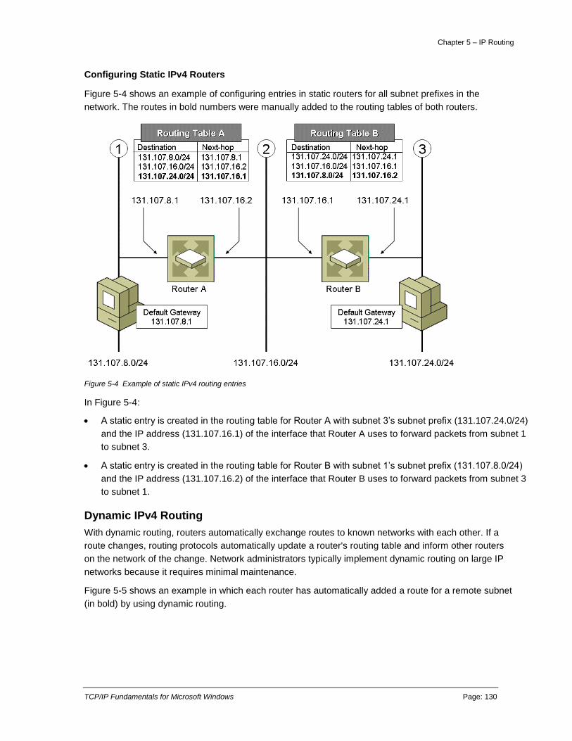
Chapter 5 – IP Routing
TCP/IP Fundamentals for Microsoft Windows Page: 130
Configuring Static IPv4 Routers
Figure 5-4 shows an example of configuring entries in static routers for all subnet prefixes in the
network. The routes in bold numbers were manually added to the routing tables of both routers.
Figure 5-4 Example of static IPv4 routing entries
In Figure 5-4:
A static entry is created in the routing table for Router A with subnet 3’s subnet prefix (131.107.24.0/24)
and the IP address (131.107.16.1) of the interface that Router A uses to forward packets from subnet 1
to subnet 3.
A static entry is created in the routing table for Router B with subnet 1’s subnet prefix (131.107.8.0/24)
and the IP address (131.107.16.2) of the interface that Router B uses to forward packets from subnet 3
to subnet 1.
Dynamic IPv4 Routing
With dynamic routing, routers automatically exchange routes to known networks with each other. If a
route changes, routing protocols automatically update a router's routing table and inform other routers
on the network of the change. Network administrators typically implement dynamic routing on large IP
networks because it requires minimal maintenance.
Figure 5-5 shows an example in which each router has automatically added a route for a remote subnet
(in bold) by using dynamic routing.

Chapter 5 – IP Routing
TCP/IP Fundamentals for Microsoft Windows Page: 131
Figure 5-5 Example of dynamic IPv4 routing entries
Dynamic routing for IPv4 requires an IPv4 routing protocol such as RIP, OSPF, or BGP-4.
RIP
RIP for IPv4 is a distance vector routing protocol that has its origins in the Xerox Network Services
(XNS) version of RIP. This routing protocol became popular due to its inclusion in Berkeley UNIX
(starting with BSD 4.2) as the RouteD server daemon. (A daemon is similar to a Windows service.) Two
versions of RIP support IPv4. RFC 1058 defines RIP version 1 (v1), and RFC 1723 defines RIP version
2 (v2).
OSPF
Open Shortest Path First (OSPF) is a link state routing protocol that runs as an Interior Gateway
Protocol (IGP) to a single autonomous system. In a link state routing protocol, each router maintains a
database of router advertisements (LSAs). LSAs for routers within the AS consist of information about a
router, its attached subnets, and their configured costs. An OSPF cost is a unitless metric that indicates
the preference of using a link. Summarized routes and routes outside of the AS also have LSAs. RFC
2328 defines OSPF.
The router distributes its LSAs to its neighboring routers, which gather them into a database called the
link state database (LSDB). By synchronizing LSDBs between all neighboring routers, each router has
each other router's LSA in its database. Therefore, every router has the same LSDB. From the LSDB,
OSPF calculates the entries for the router's routing table by determining the least cost path, which is the
path with the lowest accumulated cost, to each subnet in the network.
BGP-4
Border Gateway Protocol 4 (BGP-4) is a path vector routing protocol that RFC 4271 defines. Unlike RIP
and OSPF, which perform within an autonomous system, BGP-4 is designed to exchange information

Chapter 5 – IP Routing
TCP/IP Fundamentals for Microsoft Windows Page: 132
between autonomous systems. BGP-4 routing information is used to create a logical path tree, which
describes all the connections between autonomous systems. The path tree information is then used to
create loop-free routes in the routing tables of BGP-4 routers. BGP-4 messages use TCP port 179.
BGP-4 is the primary inter-domain protocol used to maintain routing tables on the IPv4 Internet.
Integrating Static and Dynamic Routing
A static router does not exchange routing information with dynamic routers. To route from a static router
through a dynamic router (such as an IPv4 router that is enabled for RIP or OSPF), you will need to add
a static route to the routing tables on both the static and dynamic routers. As Figure 5-6 shows:
To route packets from subnet 1 to the rest of the intranet, the routing table for Router A must include
manually configured routes for subnet 3 (131.107.24/0/8) and for the rest of the intranet (10.0.0.0/8).
To route packets from subnet 2 and 3 to the rest of the intranet, the routing table for Router B must
include manually configured routes for subnet 1 (131.107.8.0/24) and for the rest of the intranet
(10.0.0.0/8).
To route packets from subnet 3 and the rest of the intranet to subnets 1 and 2, the routing table for the
RIP router must include manually configured routes for subnet 1 (131.107.8.0/24) and subnet 2
(131.107.16.0/8).
Figure 5-6 Integrating static and dynamic routing
The routing tables in Figure 5-6 do not show the routes for directly attached subnets or other routes
learned by the RIP router.
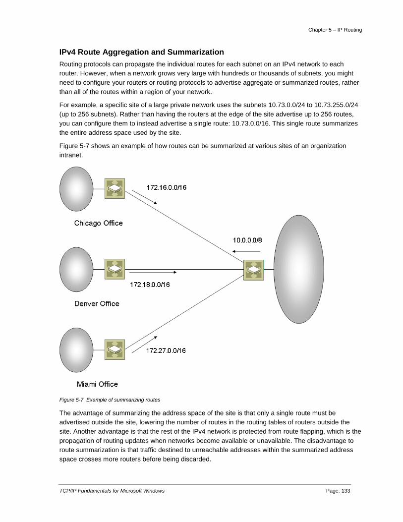
Chapter 5 – IP Routing
TCP/IP Fundamentals for Microsoft Windows Page: 133
IPv4 Route Aggregation and Summarization
Routing protocols can propagate the individual routes for each subnet on an IPv4 network to each
router. However, when a network grows very large with hundreds or thousands of subnets, you might
need to configure your routers or routing protocols to advertise aggregate or summarized routes, rather
than all of the routes within a region of your network.
For example, a specific site of a large private network uses the subnets 10.73.0.0/24 to 10.73.255.0/24
(up to 256 subnets). Rather than having the routers at the edge of the site advertise up to 256 routes,
you can configure them to instead advertise a single route: 10.73.0.0/16. This single route summarizes
the entire address space used by the site.
Figure 5-7 shows an example of how routes can be summarized at various sites of an organization
intranet.
Figure 5-7 Example of summarizing routes
The advantage of summarizing the address space of the site is that only a single route must be
advertised outside the site, lowering the number of routes in the routing tables of routers outside the
site. Another advantage is that the rest of the IPv4 network is protected from route flapping, which is the
propagation of routing updates when networks become available or unavailable. The disadvantage to
route summarization is that traffic destined to unreachable addresses within the summarized address
space crosses more routers before being discarded.

Chapter 5 – IP Routing
TCP/IP Fundamentals for Microsoft Windows Page: 134
For example, if the 10.73.252.0/24 address prefix was not assigned to any subnet (it was an address
prefix reserved for a future subnet) and the routers on the edge of the site advertised the 10.73.0.0/16
address prefix, then traffic destined to 10.73.252.19 would be forwarded all the way to the routers at the
edge of the site before being discarded. If the address space of the site was not summarized and the
individual routes for the subnets of the site were propagated to all the routers of the IPv4 network, the
router on the sending host's subnet would discard the traffic.
RIP, OSPF, and BGP-4 support route summarization. You can also summarize when configuring static
routes.
Route Summarization for Internet Address Classes: Supernetting
With the recent growth of the Internet, it became clear to the Internet authorities that the class B
address prefixes would soon be depleted. For most organizations, a class C address prefix does not
contain enough host IDs, and a class B address prefix has enough bits to provide a flexible subnetting
scheme within the organization.
To prevent the depletion of class B address prefixes, the Internet authorities devised a new method of
assigning address prefixes. Rather than assigning a class B address prefix, the Internet Corporation for
Assigned Names and Numbers (ICANN) assigns a range of class C address prefixes that contain
enough network and host IDs for the organization’s needs. This was known as supernetting, a route
summarization technique for class C address prefixes on the Internet. For example, rather than
allocating a class B address prefix to an organization that has up to 2,000 hosts, ICANN allocates a
range of eight class C address prefixes. Each class C address prefix accommodates 254 hosts, for a
total of 2,032 host IDs.
Although this technique helps conserve class B address prefixes, it creates a different problem. Using
class-based routing techniques, the routers on the Internet must have eight class C address prefix
entries in their routing tables to route IP packets to the organization. To prevent Internet routers from
becoming overwhelmed with routes, a technique called Classless Inter-Domain Routing (CIDR) is used
to collapse multiple address prefix entries into a single entry corresponding to all of the class C address
prefixes allocated to that organization.
For example, to express the situation where eight class C address prefixes are allocated starting with
address prefix 220.78.168.0:
The starting address prefix is 220.78.168.0, or 11011100 01001110 10101000 00000000
The ending address prefix is 220.78.175.0, or 11011100 01001110 10101111 00000000
Note that the first 21 bits (bolded) of all the above Class C address prefixes are the same. The last
three bits of the third octet vary from 000 to 111. The CIDR entry in the routing tables of the Internet
routers becomes 220.78.168.0/21, or 220.78.168.0, 255.255.248.0 in subnet mask notation.
A block of addresses using CIDR is known as a CIDR block. Because prefix lengths are used to
express the count, class-based address prefixes must be allocated in groups corresponding to powers
of 2.
To support CIDR, routers must be able to exchange routing information in the form of [Prefix, Prefix
Length or Subnet Mask] pairs. RIP for IP version 2, OSPF, and BGP-4 support CIDR, but RIP for IP
version 1 does not.

Chapter 5 – IP Routing
TCP/IP Fundamentals for Microsoft Windows Page: 135
On today's Internet, the term "supernetting" is obsolete. Because the Internet no longer uses Internet
address classes, distinguishing a block of Class C address prefixes as a supernetted address prefix is
no longer necessary. Instead, organizations are assigned an address space without regard to the
original Internet address class to which the address space originated. The address space is the
summarized route for all the public addresses within the organization, whether the organization decides
to subnet or not.
IPv4 Routing Support in Windows
Windows Server 2003 supports both static and dynamic IPv4 routing. Windows XP supports only static
IPv4 routing.
Static Routing
You can enable static routing through the following:
The IPEnableRouter registry entry
The Routing and Remote Access service
For computers running Windows Vista, Windows XP, Windows Server 2008, or Windows Server 2003,
you can enable static IPv4 routing by setting the
HKEY_LOCAL_MACHINE\SYSTEM\CurrentControlSet\ Services\Tcpip\Parameters\IPEnableRouter
registry entry to 1 (data type is REG_DWORD). Editing the registry is necessary only for computers
running Windows Vista or Windows XP.
For computers running Windows Server 2008 or Windows Server 2003, you should use the Routing
and Remote Access service to enable IPv4 routing rather than setting the IPEnableRouter registry
entry. To run the Routing and Remote Access Server Setup Wizard, do the following:
1. In the console tree of the Routing and Remote Access snap-in, right-click the server you want to
enable, and then click Configure And Enable Routing and Remote Access.
2. Follow the instructions in the Routing and Remote Access Server Setup Wizard.
To enable simple IPv4 routing, choose Custom Configuration on the Configuration page and LAN
Routing on the Custom Configuration page of the Routing and Remote Access Server Setup Wizard.
Dynamic Routing with RIP and OSPF
You can enable dynamic routing through the Routing and Remote Access service. To do so, first
configure and enable the Routing and Remote Access service as described in the previous section.
Then configure RIP or OSPF routing by adding the RIP and OSPF routing protocol components and
adding and configuring interfaces on which they are enabled. OSPF is not supported in Windows
Server 2008
For more information about configuring RIP and OSPF routing, see the Help and Support in Windows
Server 2008 and Windows Server 2003.
Configuring Hosts for IPv4 Routing
IPv4 hosts can use the following methods to reach remote destinations:

Chapter 5 – IP Routing
TCP/IP Fundamentals for Microsoft Windows Page: 136
Store a host-specific route to each remote destination. This method is obviously not practical or
possible, because the routing table might have to contains thousands or, in the case of the Internet,
millions of routes. The host routing table would have to change as addresses were added or removed.
Store a route to each remote subnet. Although more possible, this method is also not practical, because
the routing table would still have to contain possibly hundreds or, in the case of the Internet, tens of
thousands of routes. The host routing table would have to change as subnets were added or removed.
Store a single default route that effectively summarizes all of the locations that are not located on the
local subnet. This method is possible and practical. Only a single route is needed and does not need to
change for nodes or subnets that are added or removed from the network.
By using a default route, the knowledge of the topology of the network and the set of reachable
destinations is offloaded to the routers, rather than being a responsibility of the sending host. The
advantage to this method is ease of configuration.
The default gateway setting, which creates the default route in the IPv4 routing table, is a critical part of
the configuration of a TCP/IP host. The role of the default gateway is to provide the host with that next-
hop IPv4 address and interface for all destinations that are not located on its subnet. Without a default
gateway, communication with remote destinations is not possible, unless additional routes are added to
the IPv4 routing table.
Default Gateway Setting
You can configure a default gateway on a computer running Windows in the following ways:
When IPv4 obtains an address configuration using DHCP, the default gateway becomes the value of
the first IPv4 address in the Router DHCP option. A network administrator configures this option on the
DHCP server to specify an ordered list of one or more default gateways.
When the user specifies an alternate IPv4 address configuration, the default gateway is the IPv4
address typed in Default Gateway on the Alternate Configuration tab for the properties of the Internet
Protocol Version 4 (TCP/IPv4) or Internet Protocol (TCP/IP) component in Network Connections. You
can specify only a single default gateway.
When the IPv4 address configuration is manually specified, the default gateway is the IPv4 address
typed in Default Gateway on the General tab for the properties of the Internet Protocol Version 4
(TCP/IPv4) or Internet Protocol (TCP/IP) component. To specify multiple default gateways, you must
add them from the IP Settings tab in the advanced properties dialog box of the Internet Protocol
Version 4 (TCP/IPv4) or Internet Protocol (TCP/IP) component.
When the IPv4 address configuration is obtained using Automatic Private IP Addressing (APIPA), a
default gateway is not configured. APIPA supports only a single subnet.
The configuration of a default gateway creates a default route in the IPv4 routing table. The default
route has a destination of 0.0.0.0 with a subnet mask of 0.0.0.0. In prefix length notation, the default
route is 0.0.0.0/0, which is sometimes abbreviated to 0/0. The next-hop address, also known as the
Gateway address in the display of the route print command, is set to the IPv4 address of the default
gateway. The next-hop interface is the interface assigned the IPv4 address in the Interface column in
the display of the route print command.

Chapter 5 – IP Routing
TCP/IP Fundamentals for Microsoft Windows Page: 137
Based on the route determination process, the default route matches all destinations. If no other route
matches the destination more closely, IPv4 uses the default route to determine the next-hop address
and interface. Default route traffic is traffic destined to a remote network but that is forwarded to the
default gateway (rather than traffic destined for the default gateway's IPv4 address).
Default Route Metric
TCP/IP for Windows by default automatically calculates a metric for the default route that is based on
the speed of the adapter to which the default gateway is configured. For example, for a 100 megabit per
second (Mbps) Ethernet adapter, the default route metric is set to 20. For a 10 Mbps Ethernet adapter,
the default route metric is set to 30.
To override this behavior for DHCP-assigned default gateways, use the Default Router Metric Base
Microsoft-specific DHCP option, specifying Microsoft Windows 2000 Options as the vendor class. To
override this behavior for manually configured default gateways, open the advanced properties dialog
box for the Internet Protocol Version 4 (TCP/IPv4) or Internet Protocol (TCP/IP) component, click the IP
Settings tab, and then clear the Automatic metric check box on the TCP/IP Gateway Address dialog
box for the configured default gateways. Figure 5-8 shows the TCP/IP Gateway Address dialog box.
Figure 5-8 The TCP/IP Gateway Address dialog box
ICMP Router Discovery
ICMP Router Discovery provides an alternate method of configuring and detecting default gateways.
Instead of obtaining a default gateway configuration manually or using DHCP, IPv4 can also
dynamically discover the routers on a subnet. If the primary router fails, hosts can automatically switch
to a backup router. When a host that supports router discovery initializes, it joins the all-systems IP
multicast group (224.0.0.1) and then listens for the Router Advertisement messages that routers send
to that group. Hosts can also send Router Solicitation messages to the all-routers IP multicast address
(224.0.0.2) when an interface initializes to be configured immediately.
TCP/IP for Windows supports sending ICMP router solicitations and receiving ICMP router
advertisements, known as host-side router discovery. This capability is disabled by default and can be
enabled if you are using DHCP and the Perform Router Discovery DHCP option.
The Routing and Remote Access service in Windows Server 2008 and Windows Server 2003 supports
sending ICMP router advertisements, known as router-side router discovery. To enable router-side
ICMP router discovery, do the following:
1. In the console tree of the Routing and Remote Access snap-in, open Routing and Remote Access,
IP Routing or IPv4, and then General.
2. In the details pane, right-click the interface that you want to enable, and then click Properties.
3. On the General tab, select the Enable router discovery advertisements check box, and configure

Chapter 5 – IP Routing
TCP/IP Fundamentals for Microsoft Windows Page: 138
additional settings as needed.
Static Routes
The Route tool adds entries to the IPv4 routing table. You can add entries for hosts or networks, and
you can use IPv4 addresses or aliases. If you use aliases to specify hosts or gateways, the alias name
is looked up in the Hosts file. If you use an alias to specify an address prefix, the alias name is looked
up in the Networks file. Both of these files are in the %systemroot%\System32\Drivers\Etc folder.
The following are examples of how to use the Route tool to add entries to the host IPv4 routing table.
Example of adding an entry corresponding to a host IPv4 address:
route add 131.107.24.192 mask 255.255.255.255 131.107.1.1
or
route add 131.107.24.192 mask 255.255.255.255 router1
in which the Hosts file has the entry:
131.107.1.1 router1
Example of adding an entry corresponding to an address prefix:
route add 131.107.3.0 mask 255.255.255.0 131.107.1.2
or
route add network3 mask 255.255.255.255 131.107.1.2
in which the Networks file has the entry:
network3 131.107.3.0
Persistent Static Routes
Because the IPv4 routing table is maintained in memory, the table must be rebuilt every time the node
is restarted. To maintain static routes that are not based on the node's configuration when Windows is
restarted, the Route tool supports the -p option. The -p option makes the route persistent by storing it in
the registry at the following location:
HKEY_LOCAL_MACHINE\SYSTEM\CurrentControlSet\Services\TCPIP\PersistentRoutes
RIP Listener
RIP Listener is an optional networking component that you can install through the Programs and
Features item of Control Panel on computers running Windows Vista or the Add or Remove Programs
item of Control Panel on computers running Windows XP Professional. When installed, the RIP Listener
service listens for RIP v1 and RIP v2 traffic and uses the received RIP messages to update its IPv4
routing table. A computer using the RIP Listener service is known as a silent RIP host.
Routing for Disjoint Networks
If you have multiple interfaces and you configure a default gateway for each interface, the default route
metric, which is based on the speed of the interface, causes your fastest interface to be used for default
route traffic. This behavior might be desirable in some configurations in which the computer has
multiple adapters that are connected to the same network. For example, if you have a 100 Mbps
Chapter 5 – IP Routing
TCP/IP Fundamentals for Microsoft Windows Page: 139
Ethernet adapter and a 10 Mbps Ethernet adapter connected to the same organization intranet, you
would want the default route traffic to be sent using the 100 Mbps adapter.
However, this default behavior might be a problem when the computer is connected to two or more
disjoint networks (networks that do not provide symmetric reachability at the Network layer). Symmetric
reachability exists when packets can be sent to and received from an arbitrary destination. For
example, the Ping tool tests for symmetric reachability.
Examples of disjoint networks are the following:
Networks that have no Network layer connectivity, such as an organization intranet and a test lab that
have no IPv4 router forwarding packets between them. A computer can be connected to both networks,
but if no routes reach both networks and the computer connecting them is not forwarding packets, the
two networks are disjoint.
A privately addressed intranet that has a routed connection to the Internet. This configuration offers
asymmetric or one-way reachability. Intranet hosts can send packets to Internet hosts from private IPv4
addresses, but the return traffic cannot be delivered because routes for the private address space do
not exist in the routing infrastructure of the Internet.
Connectivity to disjoint networks is important when organizations use the following:
Either a proxy server, such as Microsoft Internet Security and Acceleration (ISA) Server, or a network
address translator (NAT) to connect their private intranets to the Internet. In either case, the address
space of the intranet is not directly accessible to Internet hosts, regardless of whether the organization
is using private or public addressing. Intranet hosts can access Internet locations indirectly through
proxy or translation, but Internet hosts cannot access arbitrary intranet locations directly. Therefore,
there is no symmetric reachability. This configuration is common for organizations that offer Internet
connectivity to their employees.
A virtual private networking (VPN) server to allow remote users or remote sites to connect to a private
intranet over the Internet. Although the VPN server is connected to both the Internet and a private
intranet and is acting as a router, the configuration of packet filters on the Internet interface prevents it
from accepting anything but VPN-based traffic. Internet hosts cannot directly reach intranet locations
without an authenticated VPN connection.
Because the TCP/IP protocol uses only a single default route in the routing table at any one time for
default route traffic, you can obtain undesirable results when default gateways are configured on
multiple interfaces that are connected to disjoint networks.
For the examples of the ISA or VPN server, the default route traffic is forwarded either to the Internet or
the intranet but not both. From the ISA or VPN server, all the locations on either the Internet or the
intranet are reachable, but you cannot reach both at the same time. However, ISA or VPN servers
require simultaneous symmetric reachability for all the locations on both the Internet and the intranet to
operate properly.
When default gateways are configured on multiple interfaces, the default route that IPv4 chooses for
current use is based on the following:
When the routing table contains multiple default routes with different metrics, the TCP/IP component of
Windows XP and Windows Server 2003 chooses the default route with the lowest metric. If the

Chapter 5 – IP Routing
TCP/IP Fundamentals for Microsoft Windows Page: 140
adapters are of different speeds, the adapter with the higher speed has the lower metric by default and
is used to forward default route traffic.
When the routing table contains multiple default routes with the lowest metric, the TCP/IP component of
Windows XP and Windows Server 2003 uses the default route that corresponds to the adapter that is
the highest in the binding order.
To prevent the problem of disjoint network unreachability, you must do the following on the ISA or VPN
server:
Configure a default gateway on the interface that is connected to the network with the largest number of
routes. In most configurations of disjoint networks, the Internet is the network with the largest number of
routes.
Do not configure a default gateway on any other interface. Instead use static routes or dynamic routing
protocols to add the routes that summarize the addresses of the other disjoint networks to the local
IPv4 routing table.
For example, an ISA server is connected to the Internet and a private intranet. The private intranet uses
the private IPv4 address space. To configure this server so that all locations on both disjoint networks
are reachable from the ISA server, you would do the following on the ISA server:
Configure a default gateway on the network adapter connected to the Internet. This step creates a
default route that points to the Internet, making all Internet locations reachable.
Add the 10.0.0.0/8, 172.16.0.0/12, and 192.168.0.0/16 routes using the intranet-connected adapter as
persistent static routes with the Route tool. This step creates the routes that summarize all the
addresses of the private intranet, making all intranet locations reachable.
In this example, static routes are added. You can also configure the ISA server as a RIP or OSPF
dynamic router so that, rather than summarizing the entire private IPv4 address space, subnet-specific
routes are dynamically added and removed from the IPv4 routing table based on the current intranet
routing topology. To use RIP or OSPF, enable and configure the Routing and Remote Access service.
Network Address Translation
A network address translator (NAT) is an IPv4 router defined in RFC 3022 that can translate the IPv4
addresses and TCP/UDP port numbers of packets as they are forwarded. For example, consider a
small business network with multiple computers that connect to the Internet. This business would
normally have to obtain a public IPv4 address for each computer on the network from an Internet
service provider (ISP). With a NAT, however, the small business can use private addressing and have
the NAT map its private addresses to a single or to multiple public IPv4 addresses.
NATs are a common solution for the following combination of requirements:
You want to leverage the use of a single connection, rather than connecting multiple computers, to the
Internet.
You want to use private addressing.
You want access to Internet resources without having to deploy a proxy server.

Chapter 5 – IP Routing
TCP/IP Fundamentals for Microsoft Windows Page: 141
How Network Address Translation Works
When a private user on the small business intranet connects to an Internet resource, the TCP/IP
protocol on the user’s computer creates an IPv4 packet with the following values set in the IPv4 and
TCP or UDP headers (bold text indicates the fields that are affected by the NAT):
Destination IP Address: Internet resource IPv4 address
Source IP Address: Private IPv4 address
Destination Port: Internet resource TCP or UDP port
Source Port: Source application TCP or UDP port
The sending host or another router forwards this IPv4 packet to the NAT, which translates the
addresses of the outgoing packet as follows:
Destination IP Address: Internet resource IPv4 address
Source IP Address: ISP-allocated public IPv4 address
Destination Port: Internet resource TCP or UDP port
Source Port: Remapped source application TCP or UDP port
The NAT sends the modified IPv4 packet over the Internet. The responding computer sends back a
response to the NAT. When the NAT receives the packet, it contains the following addressing
information:
Destination IP Address: ISP-allocated public IPv4 address
Source IP Address: Internet resource IPv4 address
Destination Port: Remapped source application TCP or UDP port
Source Port: Internet resource TCP or UDP port
When the NAT translates the addresses and forwards the packet to the intranet client, the packet
contains the following addressing information:
Destination IP Address: Private IPv4 address
Source IP Address: Internet resource IPv4 address
Destination Port: Source application TCP or UDP port
Source Port: Internet resource TCP or UDP port
For outgoing packets, the source IPv4 address and TCP/UDP port numbers are mapped to a public
source IPv4 address and a possibly changed TCP/UDP port number. For incoming packets, the
destination IPv4 address and TCP/UDP port numbers are mapped to the private IPv4 address and
original TCP/UDP port number.
For example a small business is using the 192.168.0.0/24 private address prefix for its intranet and its
ISP has allocated it a single public IPv4 address of 131.107.0.1. When a user with the private address
192.168.0.99 on the small business intranet connects to a Web server at the IPv4 address 157.60.0.1,
the user's TCP/IP protocol creates an IPv4 packet with the following values set in the IPv4 and TCP
headers:

Chapter 5 – IP Routing
TCP/IP Fundamentals for Microsoft Windows Page: 142
Destination IPv4 Address: 157.60.0.1
Source IPv4 Address: 192.168.0.99
TCP Destination Port: 80
TCP Source Port: 1025
The source host forwards this IPv4 packet to the NAT, which translates the addresses of the outgoing
packet as follows:
Destination IPv4 Address: 157.60.0.1
Source IPv4 Address: 131.107.0.1
TCP Destination Port: 80
TCP Source Port: 5000
The NAT sends the modified IPv4 packet over the Internet. The Web server sends back a response to
the NAT. When the NAT receives the response, the packet contains the following addressing
information:
Destination IPv4 Address: 131.107.0.1
Source IPv4 Address: 157.50.0.1
TCP Destination Port: 5000
TCP Source Port: 80
When the NAT translates the addresses and forwards the packet to the intranet client, the packet
contains the following addressing information:
Destination IPv4 Address: 192.168.0.99
Source IPv4 Address: 157.60.0.1
TCP Destination Port: 1025
TCP Source Port: 80
Figure 5-9 shows how the NAT translates incoming traffic for the configuration in this example.

Chapter 5 – IP Routing
TCP/IP Fundamentals for Microsoft Windows Page: 143
Figure 5-9 An example of how a NAT translates incoming traffic
The mappings for private to public traffic are stored in a NAT translation table, which can contain two
types of entries:
Dynamic mappings
Created when private network clients initiate communications. Dynamic mappings are removed
from the table after a specified amount of time, unless traffic that corresponds to an entry refreshes
it.
Static mappings
Configured manually so that communications initiated by Internet clients can be mapped to a
specific private network address and port. Static mappings are needed when there are servers (for
example, Web servers) or applications (for example, games) on the private network that you want
to make available to computers that are connected to the Internet. Static mappings are not
automatically removed from the NAT translation table.
The NAT forwards traffic from the Internet to the private network only if a mapping exists in the NAT
translation table. In this way, the NAT provides some protection for computers that are connected to
private network segments. However, you should not use a NAT in place of a fully featured firewall when
Internet security is a concern.
Windows Vista and Windows XP include network address translation capabilities with the Internet
Connection Sharing feature in the Network Connections folder. Windows Server 2008 also includes
network address translation capabilities with the NAT component of Routing and Remote Access.
Windows Server 2003 also includes network address translation capabilities with the NAT/Basic
Firewall component of Routing and Remote Access.

Chapter 5 – IP Routing
TCP/IP Fundamentals for Microsoft Windows Page: 144
IPv6 Routing
An IPv6 network consists of multiple IPv6 subnets interconnected by IPv6 routers. To provide
reachability to any arbitrary location on the IPv6 network, routes must exist on sending hosts and
routers to forward the traffic to the intended destination. These routes can either be general routes,
such as a default route that summarizes all locations, or specific routes, such as subnet routes that
summarize all locations on a specific subnet.
Hosts typically use directly attached subnet routes to reach neighboring nodes and a default route to
reach all other locations. Routers typically use specific routes to reach all locations within their sites and
summary routes to reach other sites or the Internet. Although Router Advertisement messages
automatically configure hosts with directly attached or remote subnet routes and a default route,
configuring routers is more complex. You can configure a router with static routes or with routing
protocols for dynamic routes.
Similar to IPv4 nodes, typical IPv6 nodes use a local IPv6 routing table to determine how to forward
packets. IPv6 routing table entries are created by default when IPv6 initializes, and entries are added
either through manual configuration or by the receipt of Router Advertisement messages containing on-
link prefixes and routes.
IPv6 Routing Tables
A routing table is present on all nodes running the IPv6 protocol component of Windows. The routing
table stores information about IPv6 address prefixes and how they can be reached (either directly or
indirectly). Before checking the IPv6 routing table, IPv6 checks the destination cache for an entry
matching the destination address in the IPv6 packet being forwarded. If the destination cache does not
contain an entry for the destination address, IPv6 uses the routing table to determine:
The interface used for the forwarding (the next-hop interface)
The interface identifies the physical or logical interface that is used to forward the packet to either
its destination or the next router.
The next-hop IPv6 address
For a direct delivery (in which the destination is on a local link), the next-hop address is the
destination IPv6 address in the packet. For an indirect delivery (in which the destination is not on a
local link), the next-hop IPv6 address is the address of a router.
After the next-hop interface and address are determined, IPv6 updates the destination cache. IPv6
forwards subsequent packets addressed to the destination by using the destination cache entry, rather
than checking the routing table.
IPv6 Routing Table Entry Types
IPv6 routing table entries can store the following types of routes:
Directly attached subnet routes
These routes are subnet prefixes for subnets that are directly attached and typically have a 64-bit
prefix length.

Chapter 5 – IP Routing
TCP/IP Fundamentals for Microsoft Windows Page: 145
Remote subnet routes
Remote subnet routes can be subnet prefixes (typically with a 64-bit prefix length) or prefixes that
summarize an address space (typically with a prefix length less than 64).
Host routes
For IPv6 host routes, the route prefix is a specific IPv6 address with a 128-bit prefix length. In
contrast, both types of subnet routes have prefixes that have a prefix length of 64 bits or less.
Default route
The IPv6 default route prefix is ::/0.
Route Determination Process
To determine which routing table entry is used for the forwarding decision, IPv6 on an IPv6 router uses
the following process:
1. For each entry in a routing table, compare the bits in the address prefix to the same bits in the
destination address for the number of bits indicated in the prefix length of the route. If all the bits in
the address prefix match all the bits in the destination IPv6 address, the route is a match for the
destination.
2. Compile the list of matching routes and choose the route that has the largest prefix length (the route
that matched the most high-order bits with the destination address). The longest matching route is
the most specific route to the destination. If multiple entries with the longest match are found (multiple
routes to the same address prefix, for example), the router uses the lowest metric to select the best
route. If multiple entries exist that are the longest match and the lowest metric, IPv6 can choose
which routing table entry to use.
For any given destination, this procedure finds matching routes in the following order:
1. A host route that matches the entire destination address
2. A subnet or summarized route with the longest prefix length that matches the destination
3. The default route (the address prefix ::/0)
When the route determination process is complete, IPv6 has selected a single route in the routing table.
The selected route yields a next-hop interface and address. If the sending host fails to find a route, IPv6
assumes that the destination is locally reachable. If a router fails to find a route, IPv6 sends an Internet
Control Message Protocol for IPv6 (ICMPv6) Destination Unreachable-No Route to Destination
message to the sending host and discards the packet.
On an IPv6 sending host, the entries in the routing table that are used for route determination depend
on whether the host supports strong host send behavior. Hosts running Windows Vista, Windows XP,
Windows Server 2008, or Windows Server 2003 support strong host sends. For more information, see
Strong and Weak Host Models.
Example Windows IPv6 Routing Table
To view the IPv6 routing table on a computer running Windows, type route print or netsh interface
ipv6 show routes at a command prompt. Here is the abbreviated display of the netsh interface ipv6
show routes command for a computer that has three network adapters, that is acting as a default

Chapter 5 – IP Routing
TCP/IP Fundamentals for Microsoft Windows Page: 146
router for two subnets configured with global address prefixes, and that has a default route pointing to a
default router on a third subnet:
Publish Type Met Prefix Idx Gateway/Interface Name
------- -------- ---- ------------------------ --- ------------------------
yes Autoconf 8 2001:db8:0:1::/64 4 Local Area Connection
yes Autoconf 8 2001:db8:0:2::/64 5 Local Area Connection 2
yes Autoconf 8 2001:db8:0:3::/64 6 Local Area Connection 3
yes Manual 256 ::/0 6 fe80::210:ffff:fed6:58c0
Each entry in the IPv6 routing table has the following fields:
Whether the route is published (advertised in a Routing Advertisement message).
The route type. Routes that user applications configure have the route type of Manual. Routes that the
IPv6 protocol configures have the route type of Autoconf.
A metric used to select between multiple routes with the same prefix. The lowest metric is the most
desirable closest matching route.
The prefix.
The interface index, which indicates the interface over which packets matching the address prefix are
reachable.
You can view the interface indexes from the display of the netsh interface ipv6 show interface
command.
A next-hop IPv6 address or an interface name.
For remote subnet routes, a next-hop IPv6 address is listed. For directly attached subnet routes,
the name of the interface from which the address prefix is directly reachable is listed.
The IPv6 routing table is built automatically, based on the current IPv6 configuration of your computer.
A route for the link-local prefix (FE80::/64) is never present in the IPv6 routing table.
The first, second, and third routes are for the 64-bit global address prefixes of locally attached subnets.
An Ethernet network adapter named Local Area Connection (interface index 4) is connected to the
subnet 2001:DB8:0:1::/64. A second Ethernet network adapter named Local Area Connection 2
(interface index 5) is connected to the subnet 2001:DB8:0:2::/64. A third Ethernet network adapter
named Local Area Connection 3 (interface index 6) is connected to the subnet 2001:DB8:0:3::/64.
The fourth route is the default route (prefix of ::/0). The default route matches all destinations. If the
default route is the longest matching route for the destination, the packet is forwarded to the IPv6
address FE80::210:FFFF:FED6:58C0 by using the Ethernet network adapter named Local Area
Connection 3 (interface index 6).
When determining the next-hop IPv6 address from a route in the routing table, IPv6 does the following:
If the Gateway/Interface Name column of the routing table entry indicates an interface name, the
destination is a neighbor, and IPv6 sets the next-hop address to the destination address of the IPv6
packet.
Chapter 5 – IP Routing
TCP/IP Fundamentals for Microsoft Windows Page: 147
If the Gateway/Interface Name column of the routing table entry indicates an address (the address of a
neighboring router), the destination is remote, and IPv6 sets the next-hop address to the address in the
Gateway/Interface Name column.
For example, when traffic is sent to 2001:DB8:0:2:2AA:FF:FE90:4D3C, the longest matching route is
the route for the directly attached subnet 2001:DB8:0:2::/64. The forwarding IP address is set to the
destination address of 2001:DB8:0:2:2AA:FF:FE90:4D3C, and the interface is the interface that
corresponds to interface index 5 (the Ethernet network adapter named Local Area Connection 2). When
traffic is sent to 2001:DB8:0:9:2AA:FF:FE03:21A6, the longest matching route is the default route (::/0).
The forwarding IP address is set to the router address of FE80::210:FFFF:FED6:58C0, and the
interface is the interface that corresponds to interface index 6 (the Ethernet network adapter named
Local Area Connection 3).
IPv6 Routing Protocols
The following routing protocols are defined for IPv6:
RIPng for IPv6
OSPF for IPv6
Integrated Intermediate System-to-Intermediate System (IS-IS) for IPv6
BGP-4
Inter-Domain Routing Protocol version 2 (IDRPv2)
RIPng for IPv6
RIP Next Generation (RIPng) is a distance vector routing protocol for IPv6 that is defined in RFC 2080.
RIPng for IPv6 is an adaptation of the RIP v2 protocol—defined in RFC 1723—to advertise IPv6
address prefixes. RIPng for IPv6 uses UDP port 521 to periodically advertise its routes, respond to
requests for routes, and advertise route changes.
RIPng for IPv6 has a maximum distance of 15, in which 15 is the accumulated cost (hop count).
Locations that are a distance of 16 or further are considered unreachable. RIPng for IPv6 is a simple
routing protocol with a periodic route-advertising mechanism designed for use in small- to medium-
sized IPv6 networks. RIPng for IPv6 does not scale well to a large or very large IPv6 network.
OSPF for IPv6
OSPF for IPv6 is a link state routing protocol defined in RFC 2740 and designed for routing table
maintenance within a single autonomous system. OSPF for IPv6 is an adaptation of the OSPF routing
protocol version 2 for IPv4 defined in RFC 2328. The OSPF cost of each router link is a unitless number
that the network administrator assigns, and it can include delay, bandwidth, and monetary cost factors.
The accumulated cost between network segments in an OSPF network must be less than 65,535.
OSPF messages are sent as upper layer protocol data units (PDUs) using the next header value of 89.
Integrated IS-IS for IPv6
Integrated IS-IS, also known as dual IS, is a link state routing protocol that is very similar to OSPF and
that is defined in International Standards Organization (ISO) document 10589. IS-IS supports both IPv4
and Connectionless Network Protocol (CLNP) (the Network layer of the Open Systems Interconnection

Chapter 5 – IP Routing
TCP/IP Fundamentals for Microsoft Windows Page: 148
[OSI] protocol suite). IS-IS allows two levels of hierarchical scaling, whereas OSPF allows only one
(areas).
A detailed explanation of Integrated IS-IS for IPv6 is beyond the scope of this chapter. For more
information, see ISO 10589 and the Internet draft titled "Routing IPv6 with IS-IS."
BGP-4
Border Gateway Protocol Version 4 (BGP-4) is a path vector routing protocol defined in RFC 4271.
Unlike RIPng for IPv6 and OSPF for IPv6, which are used within an autonomous system, BGP-4 is
designed to exchange routing information between autonomous systems. BGP-4 routing information is
used to create a logical path tree, which describes all the connections between autonomous systems.
The path tree information is then used to create loop-free routes in the routing tables of BGP-4 routers.
BGP-4 messages are sent using TCP port 179. BGP-4 is the primary inter-domain protocol used to
maintain routing tables on the IPv4 Internet.
BGP-4 has been defined to be independent of the address family for which routing information is being
propagated. For IPv6, BGP-4 has been extended to support IPv6 address prefixes as described in
RFCs 2545 and 4760.
A detailed explanation of BGP-4 for IPv6 is beyond the scope of this chapter. For more information, see
RFCs 4271, 2545, and 4760.
IPv6 Route Aggregation and Summarization
Just like in IPv4, you can aggregate or summarize IPv6 routing information at boundaries of address
spaces. The best examples are the 48-bit address prefixes that IANA or an ISP assigns to the individual
sites of an organization. The 48-bit prefix summarizes all the addresses used within the site. The 64-bit
prefixes that correspond to individual subnets within the site are not advertised outside the site.
Within the site, organizations are free to use any route aggregation scheme they want within the 16-bit
Subnet ID field of the IPv6 global address format. Figure 5-10 shows an example.

Chapter 5 – IP Routing
TCP/IP Fundamentals for Microsoft Windows Page: 149
Figure 5-10 An example of route aggregation for an IPv6 unicast address prefix
Windows Support for IPv6 Static Routing
The IPv6 protocol component of Windows supports static routing. You can configure a computer
running Windows as a static IPv6 router by enabling forwarding on the computer's interfaces and then
configuring it to advertise subnet prefixes to local hosts.
Figure 5-11 shows an example network using a simple static routing configuration. The configuration
consists of three subnets, three host computers running Windows (Host A, Host B, and Host C), and
two router computers running Windows (Router 1 and Router 2).

Chapter 5 – IP Routing
TCP/IP Fundamentals for Microsoft Windows Page: 150
Figure 5-11 Static routing example with the IPv6 protocol component of Windows
After the IPv6 protocol is installed on all computers on this example network, you must enable
forwarding and advertising over the two network adapters of Router 1 and Router 2. Use the following
command:
netsh interface ipv6 set interface InterfaceNameOrIndex forwarding=enabled advertise=enabled
in which InterfaceNameorIndex is the name of the network connection in the Network Connections
folder or the interface index number from the display of the netsh interface ipv6 show interface
command. You can use either the interface name or its index number. In Windows Server 2008, you
can also use the Routing and Remote Access snap-in to enable IPv6 routing.
For example, for Router 1, if the interface index of the network adapter connected to Subnet 1 is 4 and
the interface index of the network adapter connected to Subnet 2 is 5, the commands would be:
netsh int ipv6 set interface 4 forwarding=enabled advertise=enabled
netsh int ipv6 set interface 5 forwarding=enabled advertise=enabled
After you enable forwarding and advertising, you must configure the routers with the address prefixes
for their attached subnets. For the IPv6 in Windows, you do this by adding routes to the router's routing
table with instructions to advertise the route. Use the following command:
netsh interface ipv6 set route Address/PrefixLength InterfaceNameOrIndex publish=yes
in which Address is the address portion of the prefix and PrefixLength is the prefix length portion of the
prefix. To publish a route (to include it in a router advertisement), you must specify publish=yes.
For example, for Router 1 using the example interface indexes, the commands are:
netsh int ipv6 set route 2001:DB8:0:1::/64 4 publish=yes
netsh int ipv6 set route 2001:DB8:0:2::/64 5 publish=yes

Chapter 5 – IP Routing
TCP/IP Fundamentals for Microsoft Windows Page: 151
The result of this configuration is the following:
Router 1 sends Router Advertisement messages on Subnet 1. These messages contain a Prefix
Information option to autoconfigure addresses for Subnet 1 (2001:DB8:0:1::/64), a Maximum
Transmission Unit (MTU) option for the link MTU of Subnet 1, and a Route Information option for the
subnet prefix of Subnet 2 (2001:DB8:0:2::/64).
Router 1 sends Router Advertisement messages on Subnet 2. These messages contain a Prefix
Information option to autoconfigure addresses for Subnet 2 (2001:DB8:0:2::/64), an MTU option for the
link MTU of Subnet 2, and a Route Information option for the subnet prefix of Subnet 1
(2001:DB8:0:1::/64).
When Host A receives the Router Advertisement message, the host automatically configures a global
address on its network adapter interface with the prefix 2001:DB8:0:1::/64 and an Extended Unique
Identifier (EUI)-64-derived interface identifier. The host also adds a route for the locally attached Subnet
1 (2001:DB8:0:1::/64) and a route for Subnet 2 (2001:DB8:0:2::/64) with the next-hop address of the
link-local address of Router 1's interface on Subnet 1 to its routing table.
When Host B receives the Router Advertisement message, the host automatically configures a global
address on its network adapter interface with the prefix 2001:DB8:0:2::/64 and an EUI-64-derived
interface identifier. The host also adds a route for the locally attached Subnet 2 (2001:DB8:0:2::/64) and
a route for Subnet 1 (2001:DB8:0:1::/64) with the next-hop address of the link-local address of Router
1's interface on Subnet 2 to its routing table.
In this configuration, Router 1 does not advertise itself as a default router (the Router Lifetime field in
the Router Advertisement message is set to 0), and the routing tables of Host A and Host B do not
contain default routes. A computer running the IPv6 protocol component for Windows Server 2003 or
Windows XP will not advertise itself as a default router unless a default route is configured to be
published.
To continue this example configuration, the interface index of Router 2's network adapter connected to
Subnet 2 is 4, and the interface index of Router 2's network adapter connected to Subnet 3 is 5. To
provide connectivity between Subnet 2 and Subnet 3, you would issue the following commands on
Router 2:
netsh int ipv6 set interface 4 forwarding=enabled advertise=enabled
netsh int ipv6 set interface 5 forwarding=enabled advertise=enabled
netsh int ipv6 set route 2001:DB8:0:2::/64 4 publish=yes
netsh int ipv6 set route 2001:DB8:0:3::/64 5 publish=yes
The result of this configuration is the following:
Router 2 sends Router Advertisement messages on Subnet 2. These messages contain a Prefix
Information option to autoconfigure addresses for Subnet 2 (2001:DB8:0:2::/64), an MTU option for the
link MTU of Subnet 2, and a Route Information option for the subnet prefix of Subnet 3
(2001:DB8:0:3::/64).
Router 2 sends Router Advertisement messages on Subnet 3. These messages contain a Prefix
Information option to autoconfigure addresses for Subnet 3 (2001:DB8:0:3::/64), an MTU option for the

Chapter 5 – IP Routing
TCP/IP Fundamentals for Microsoft Windows Page: 152
link MTU of Subnet 3, and a Route Information option for the subnet prefix of Subnet 2
(2001:DB8:0:2::/64).
When Host B receives the Router Advertisement message from Router 2, the host does not
automatically configure a global address using the 2001:DB8:0:2::/64 prefix, because a global address
with that prefix already exists. Host B also adds a route for Subnet 3 (2001:DB8:0:3::/64) with the next-
hop address of the link-local address of Router 2's interface on Subnet 2 to its routing table.
When Host C receives the Router Advertisement message, the host automatically configures a global
address on its network adapter interface with the prefix 2001:DB8:0:3::/64 and an EUI-64-derived
interface identifier. It also adds a route for the locally attached subnet (Subnet 3) (2001:DB8:0:3::/64)
and a route for Subnet 2 (2001:DB8:0:2::/64) with the next-hop address of the link-local address of
Router 2's interface on Subnet 3 to its routing table.
The result of this configuration is that, although Host B can communicate with both Host A and Host C,
Host A and Host C cannot communicate because Host A has no routes to Subnet 3 and Host C has no
routes to Subnet 1. You can solve this problem in either of two ways:
Configure Router 1 to publish a route to Subnet 3 with the next-hop address of Router 2's link-local
address on Subnet 2, and configure Router 2 to publish a route to Subnet 1 with the next-hop address
of Router 1's link-local address on Subnet 2.
Configure Router 1 to publish a default route with the next-hop address of Router 2's link-local address
on Subnet 2, and configure Router 2 to publish a default route with the next-hop address of Router 1's
link-local address on Subnet 2.
For the first solution, Router 1 will advertise two Route Information options on Subnet 1—one for
Subnet 2 and one for Subnet 3. Therefore, Host A will add two routes to its routing table—one for
2001:DB8:0:2::/64 and 2001:DB8:0:3::/64. Router 1 will continue to advertise only one Route
Information option (for Subnet 1) on Subnet 2. Similarly, Router 2 will advertise two Route Information
options on Subnet 3—one for Subnet 1 and one for Subnet 2. Therefore, Host C will add two routes to
its routing table—one for 2001:DB8:0:1::/64 and 2001:DB8:0:2::/64. Router 2 will continue to advertise
only one Route Information option (for Subnet 3) on Subnet 2. The result of this configuration is that all
the hosts and all the routers have specific routes to all the subnets.
For the second solution, Router 1 will advertise itself as a default router with one Route Information
option (for Subnet 2) on Subnet 1. Therefore, Host A will add two routes to its routing table—one for the
default route ::/0 and one for 2001:DB8:0:2::/64. Similarly, Router 2 will advertise itself as a default
router with one Route Information option (for Subnet 2) on Subnet 3. Therefore, Host C will add two
routes to its routing table—one for the default route ::/0 and one for 2001:DB8:0:2::/64. The result of this
configuration is that all the hosts and all the routers have a combination of specific and general routes
to all the subnets, with the exception of Host B, which has only specific routes to all the subnets. The
problem with solution 2 is that Router 1 and Router 2 have default routes pointing to each other. Any
non-link-local traffic sent from Host A or Host C that does not match the prefix 2001:DB8:0:1::/64,
2001:DB8:0:2::/64, or 2001:DB8:0:3::/64 is sent in a routing loop between Router 1 and Router 2.
You could extend this network of three subnets and two routers to include more subnets and more
routers. However, the administrative overhead to manage the configuration of the static routers does
not scale. At some point, you would want to use an IPv6 routing protocol.

Chapter 5 – IP Routing
TCP/IP Fundamentals for Microsoft Windows Page: 153
Configuring Hosts for IPv6 Routing
IPv6 hosts are configured for routing through the router discovery process, which requires no
configuration. When an initializing IPv6 host receives a Router Advertisement message, IPv6
automatically configures the following:
On-link subnet prefixes that correspond to autoconfiguration address prefixes contained within the
Router Advertisement message.
Off-link subnet prefixes that correspond to specific routes contained within the Router Advertisement
message.
A default route, if the router sending the Router Advertisement message is advertising itself as a default
router.
Because the typical IPv6 host is automatically configuring all the routes that it typically needs to forward
packets to an arbitrary destination, you do not need to configure routes on IPv6 hosts.

Chapter 5 – IP Routing
TCP/IP Fundamentals for Microsoft Windows Page: 154
Routing Tools
Windows includes the following command-line utilities that you can use to test reachability and routing
and to maintain the routing tables:
Route
Displays the local IPv4 and IPv6 routing tables. You can use the Route tool to add temporary and
persistent routes, change existing routes, and remove routes from the IPv4 routing table. You can
use the Route tool in Windows Vista and Windows Server 2008 to add routes, change existing
routes, and remove routes from the IPv6 routing table.
Netsh interface ipv6
Displays the IPv6 routing table (netsh interface ipv6 show routes), adds routes (netsh interface
ipv6 add route), removes routes (netsh interface ipv6 delete route), and modifies existing routes
(netsh interface ipv6 set route).
Ping
Verifies IP-level connectivity to another TCP/IP computer by sending either ICMP Echo or ICMPv6
Echo Request messages. The tool displays the receipt of corresponding Echo Reply messages,
along with round-trip times. Ping is the primary TCP/IP tool used to troubleshoot connectivity,
reachability, and name resolution.
Tracert
Determines the path taken to a destination by sending ICMP Echo or ICMPv6 Echo Request
messages to the destination with incrementally increasing Time to Live (TTL) or Hop Count field
values. The path displayed is the list of near-side router interfaces of the routers in the path
between a source host and a destination. The near-side interface is the interface of the router that
is closest to the sending host in the path.
Pathping
Provides information about network latency and network loss at intermediate hops between a
source and a destination. Pathping sends multiple ICMP Echo or ICMPv6 Echo Request messages
to each router between a source and destination over a period of time and then computes results
based on the packets returned from each router. Because Pathping displays the degree of packet
loss at any given router or link, you can determine which routers or links might be having network
problems.

Chapter 5 – IP Routing
TCP/IP Fundamentals for Microsoft Windows Page: 155
Chapter Summary
The chapter includes the following pieces of key information:
IP routing is the process of forwarding a packet based on the destination IP address. IP uses a routing
table to determine the next-hop IP address and interface for a packet being sent or forwarded.
IP routing is a combination of direct and indirect deliveries. Direct delivery occurs when the IP node
forwards a packet to the final destination on a directly attached subnet, and indirect delivery occurs
when the IP node forwards a packet to an intermediate router.
Static routing relies on the manual administration of the routing table. Dynamic routing relies on routing
protocols, such as RIP and OSPF, to dynamically update the routing table through the exchange of
routing information between routers.
The TCP/IP component of Windows uses a local IPv4 routing table to determine the route used to
forward the packet. From the chosen route, the next-hop IPv4 address and interface are determined.
IPv4 hands the packet to ARP to resolve the next-hop address to a MAC address and send the packet.
You can use the route print command to view the IPv4 routing table for the TCP/IP component of
Windows.
Rather than use routes for the address prefixes of every subnet in your network, you can use route
summarization to advertise a summarized address prefix that includes all the subnets in a specific
region of your network.
An IPv4 host is configured with a default gateway. IPv4 static routers are configured with either subnet
routes or summarized routes. IPv4 dynamic routers are configured with the settings that allow them to
exchange routing information with neighboring routers.
A network address translator (NAT) is an IPv4 router that can translate the IP addresses and TCP/UDP
port numbers of packets as they are forwarded. A NAT allows a small network to share a single public
IPv4 address.
The IPv6 component of Windows uses a local IPv6 routing table to determine the route used to forward
the packet. From the chosen route, IPv6 determines the next-hop IPv6 address and interface. IPv6
hands the packet to the Neighbor Discovery process to resolve the next-hop address to a MAC address
and send the packet. You can use the route print or netsh interface ipv6 show routes command to
view the routing table for the IPv6 component of Windows.
IPv6 hosts automatically configure themselves with routing information based on the receipt of Router
Advertisement messages. You must use netsh interface ipv6 commands to manually enable and
configure routers running the IPv6 component of Windows to advertise address prefixes and routes.
You use the Route and Netsh tools to manage IP routing tables. You use the Ping tool to test basic
reachability. You use the Tracert tool to show the path that a packet takes from source to a destination.
You use the Pathping tool to test for link and router reliability in a path from a source to a destination.

Chapter 5 – IP Routing
TCP/IP Fundamentals for Microsoft Windows Page: 156
Chapter Glossary
default gateway – A configuration parameter for TCP/IP in Windows that is the IPv4 address of a
neighboring IPv4 router. Configuring a default gateway creates a default route in the IPv4 routing table.
default route – A route that summarizes all possible destinations and is used for forwarding when the
routing table does not contain any other more specific routes for the destination. For example, if a
router or sending host cannot find a subnet route, a summarized route, or a host route for the
destination, IP selects the default route. The default route is used to simplify the configuration of hosts
and routers. For IPv4 routing tables, the default route is the route with the network destination of 0.0.0.0
and netmask of 0.0.0.0. For IPv6 routing tables, the default route has the address prefix ::/0.
direct delivery – The delivery of an IP packet by an IP node to the final destination on a directly
attached subnet.
distance vector – A routing protocol technology that propagates routing information in the form of an
address prefix and its “distance” (hop count).
host route – A route to a specific IP address. Host routes allow packets to be routed on a per-IP
address basis. For IPv4 host routes, the route prefix is a specific IPv4 address with a 32-bit prefix
length. For IPv6 host routes, the route prefix is a specific IPv6 address with a 128-bit prefix length.
indirect delivery – The delivery of an IP packet by an IP node to an intermediate router.
link state – A routing protocol technology that exchanges routing information consisting of a router’s
attached subnet prefixes and their assigned costs. Link state information is advertised upon startup and
when changes in the network topology are detected.
longest matching route – The algorithm used to select the routes in the routing table that most closely
match the destination address of the packet being sent or forwarded.
NAT – See network address translator (NAT).
network address translator (NAT) – An IPv4 router that translates addresses and ports when forwarding
packets between a privately addressed network and the Internet.
next-hop determination – The process of determining the next-hop address and interface for sending or
forwarding a packet, based on the contents of the routing table.
Open Shortest Path First (OSPF) – A link state-based routing protocol for use within a single
autonomous system. An autonomous system is a portion of the network under the same administrative
authority.
OSPF – See Open Shortest Path First (OSPF).
path vector – A routing protocol technology that exchanges sequences of hop information that indicate
the path for a route. For example, BGP-4 exchanges sequences of autonomous system numbers.
RIP – See Routing Information Protocol (RIP).
route determination process – The process of determining which single route in the routing table to use
for forwarding a packet.
Chapter 5 – IP Routing
TCP/IP Fundamentals for Microsoft Windows Page: 157
route summarization – The practice of using address prefixes to summarize the address spaces of
regions of a network, rather than using the routes for individual subnets.
router – An IPv4 or IPv6 node that can forward received packets that are not addressed to itself (also
called a gateway for IPv4).
Router Advertisement – For IPv4, a message sent by a router that supports ICMP router discovery. For
IPv6, an IPv6 Neighbor Discovery message sent by a router that typically contains at least one Prefix
Information option, from which hosts create stateless autoconfigured unicast IPv6 addresses and
routes.
router discovery – For IPv4, the ability of hosts to automatically configure and reconfigure a default
gateway. For IPv6, a Neighbor Discovery process in which a host discovers the neighboring routers on
an attached link.
Routing Information Protocol (RIP) – A distance vector-based routing protocol used in small and
medium sized networks.
routing protocols – A series of periodic or on-demand messages that contain routing information that is
exchanged between dynamic routers.
routing table – The set of routes used to determine the next-hop address and interface for IP traffic sent
by a host or forwarded by a router.
static routing – The use of manually configured routes in the routing tables of routers.
supernetting – The obsolete use of route summarization to assign blocks of Class C address prefixes
on the Internet.

Chapter 5 – IP Routing
TCP/IP Fundamentals for Microsoft Windows Page: 158

Chapter 6 – Dynamic Host Configuration Protocol
TCP/IP Fundamentals for Microsoft Windows Page: 159
Chapter 6 – Dynamic Host Configuration Protocol
Abstract
This chapter describes the details of the Dynamic Host Configuration Protocol (DHCP) and its use to automatically
allocate unique IPv4 address configurations to DHCP client computers. Network administrators must understand how
DHCP works so that they can correctly configure the components of a DHCP infrastructure to allocate IPv4 addresses
and other configuration options for DHCP clients on one or more subnets. This chapter also describes how IPv6 hosts
use address autoconfiguration and the DHCP for IPv6 (DHCPv6) protocol and how you can manage IP configuration
with the Ipconfig tool.
Chapter 6 – Dynamic Host Configuration Protocol
TCP/IP Fundamentals for Microsoft Windows Page: 160
Chapter Objectives
After completing this chapter, you will be able to:
Describe the function of DHCP.
Explain how DHCP works.
Install and configure the DHCP Server service.
Configure a DHCP scope, a superscope, and scope options.
Describe the function of DHCP user and vendor classes.
Install and configure a DHCP relay agent.
Describe how IPv6 address autoconfiguration works.
Describe how DHCPv6 works.
Configure a DHCPv6 scope.
Install and configure a DHCPv6 relay agent.
Use the Ipconfig tool to view IP configurations and to manage DHCP-allocated IPv4 address
configurations.
Chapter 6 – Dynamic Host Configuration Protocol
TCP/IP Fundamentals for Microsoft Windows Page: 161
DHCP Overview
DHCP is a TCP/IP standard that reduces the complexity and administrative overhead of managing
network client IPv4 addresses and other configuration parameters. A properly configured DHCP
infrastructure eliminates the configuration problems associated with manually configuring TCP/IP.
A DHCP infrastructure consists of the following elements:
DHCP servers
Computers that offer dynamic configuration of IPv4 addresses and related configuration parameters
to DHCP clients.
DHCP clients
Network nodes that support the ability to communicate with a DHCP server to obtain a dynamically
leased IPv4 address and related configuration parameters.
DHCP relay agents
Network nodes, typically routers, that listen for broadcast and unicast DHCP messages and relay
them between DHCP servers and DHCP clients. Without DHCP relay agents, you would have to
install a DHCP server on each subnet that contains DHCP clients.
Each time a DHCP client starts, it requests IPv4 addressing information from a DHCP server, including:
IPv4 address
Subnet mask
Additional configuration parameters, such as a default gateway address, Domain Name System (DNS)
server addresses, a DNS domain name, and Windows Internet Name Service (WINS) server
addresses.
When a DHCP server receives a request, it selects an available IPv4 address from a pool of addresses
defined in its database (along with other configuration parameters) and offers it to the DHCP client. If
the client accepts the offer, the IPv4 addressing information is leased to the client for a specified period
of time.
The DHCP client will typically continue to attempt to contact a DHCP server if a response to its request
for an IPv4 address configuration is not received, either because the DHCP server cannot be reached
or because no more IPv4 addresses are available in the pool to lease to the client. For DHCP clients
that are based on Microsoft Windows XP or Windows Server 2003 operating systems, the DHCP Client
service uses the alternate configuration when it cannot contact a DHCP server. The alternate
configuration can be either an Automatic Private IP Addressing [APIPA] address or an alternate
configuration that has been configured manually.
Requests for Comments (RFCs) 2131 and 2132 define the operation of DHCP clients and servers. RFC
1542 defines the operation of DHCP relay agents. All DHCP messages are sent using the User
Datagram Protocol (UDP). DHCP clients listen on UDP port 67. DHCP servers listen on UDP port 68.
DHCP relay agents listen on both UDP ports.

Chapter 6 – Dynamic Host Configuration Protocol
TCP/IP Fundamentals for Microsoft Windows Page: 162
Benefits of Using DHCP
To understand why DHCP is beneficial in configuring TCP/IP on client computers, it is useful to contrast
the manual configuration method with the DHCP method.
Configuring TCP/IP Manually
Correct operation of TCP/IP on a host computer requires careful configuration of an IPv4 address,
subnet mask, and default gateway before the client can communicate with other network nodes. If the
configuration is incorrect, the following might happen:
A user who configures a random IPv4 address, instead of getting a valid IPv4 address from a network
administrator, can create network problems that are difficult to troubleshoot.
An error in typing one of the numbers for the IPv4 address, subnet mask, or default gateway can also
lead to problems. These problems can range from trouble communicating using TCP/IP (if the default
gateway or subnet mask is wrong) to problems with attempting to use a duplicate IPv4 address.
If the network node moves to another subnet, the IPv4 address, subnet mask, and default gateway are
no longer valid and cannot be used for TCP/IP-based connectivity.
Correct manual configuration is especially important for wireless LANs. For example, a wireless user
using a wireless-enabled laptop computer moves from one building to another in a corporate campus.
When the user and their laptop change buildings, they might switch to another subnet. Without
automated configuration, the user must manually type a different IPv4 address, subnet mask, and
default gateway for the new subnet to restore TCP/IP connectivity.
Configuring TCP/IP Using DHCP
Using DHCP to automatically configure IPv4 address configurations means the following:
Users no longer need to acquire IPv4 address configurations from a network administrator to properly
configure TCP/IP.
When a DHCP client is started, it automatically receives an IPv4 address configuration that is
correct for the attached subnet from a DHCP server. When the DHCP client moves to another
subnet, it automatically obtains a new IPv4 address configuration for that subnet.
The DHCP server supplies all of the necessary configuration information to all DHCP clients.
As long as the DHCP server has been correctly configured, all DHCP clients of the DHCP server
are configured correctly.
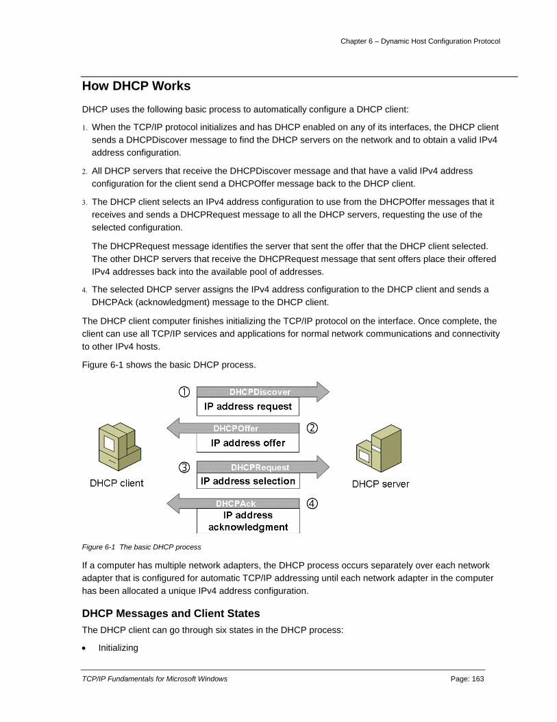
Chapter 6 – Dynamic Host Configuration Protocol
TCP/IP Fundamentals for Microsoft Windows Page: 163
How DHCP Works
DHCP uses the following basic process to automatically configure a DHCP client:
1. When the TCP/IP protocol initializes and has DHCP enabled on any of its interfaces, the DHCP client
sends a DHCPDiscover message to find the DHCP servers on the network and to obtain a valid IPv4
address configuration.
2. All DHCP servers that receive the DHCPDiscover message and that have a valid IPv4 address
configuration for the client send a DHCPOffer message back to the DHCP client.
3. The DHCP client selects an IPv4 address configuration to use from the DHCPOffer messages that it
receives and sends a DHCPRequest message to all the DHCP servers, requesting the use of the
selected configuration.
The DHCPRequest message identifies the server that sent the offer that the DHCP client selected.
The other DHCP servers that receive the DHCPRequest message that sent offers place their offered
IPv4 addresses back into the available pool of addresses.
4. The selected DHCP server assigns the IPv4 address configuration to the DHCP client and sends a
DHCPAck (acknowledgment) message to the DHCP client.
The DHCP client computer finishes initializing the TCP/IP protocol on the interface. Once complete, the
client can use all TCP/IP services and applications for normal network communications and connectivity
to other IPv4 hosts.
Figure 6-1 shows the basic DHCP process.
Figure 6-1 The basic DHCP process
If a computer has multiple network adapters, the DHCP process occurs separately over each network
adapter that is configured for automatic TCP/IP addressing until each network adapter in the computer
has been allocated a unique IPv4 address configuration.
DHCP Messages and Client States
The DHCP client can go through six states in the DHCP process:
Initializing

Chapter 6 – Dynamic Host Configuration Protocol
TCP/IP Fundamentals for Microsoft Windows Page: 164
Selecting
Requesting
Bound
Renewing
Rebinding
DHCP clients and servers use the following messages to communicate during the DHCP configuration
process:
DHCPDiscover (sent from client to server)
DHCPOffer (sent from server to client)
DHCPRequest (sent from client to server)
DHCPAck (sent from server to client)
DHCPNak (sent from server to client)
DHCPDecline (sent from client to server)
DHCPRelease (sent from client to server)
Figure 6-2 shows DHCP client states and messages, which are discussed in detail in the following
sections.
Figure 6-2 DHCP states and messages
Computers running Windows XP or Windows Server 2003 use an additional DHCP message, the
DHCPInform message, to request and obtain information from a DHCP server for the following
purposes:
To detect authorized DHCP servers in an environment that includes the Active Directory® directory
service.

Chapter 6 – Dynamic Host Configuration Protocol
TCP/IP Fundamentals for Microsoft Windows Page: 165
To obtain updated addresses for DNS servers and WINS servers and a DNS domain name when
making a remote access connection.
To obtain additional configuration parameters.
The Initializing State
In the Initializing state, the DHCP client is trying to initialize TCP/IP and it does not yet have an IPv4
address configuration. This state occurs the first time the TCP/IP protocol stack is initialized after being
configured for automatic configuration and when the DHCP client cannot renew the lease on an IPv4
address configuration.
When the DHCP client is in the Initializing state, its IPv4 address is 0.0.0.0, also known as the
unspecified address. The DHCP client's first task is to obtain an IPv4 address configuration by
broadcasting a DHCPDiscover message from UDP port 67 to UDP port 68. Because the DHCP client
does not yet have an IPv4 address and has not determined the IPv4 addresses of any DHCP servers,
the source IPv4 address for the DHCPDiscover broadcast is the unspecified address, 0.0.0.0, and the
destination is the limited broadcast address, 255.255.255.255. The DHCPDiscover message contains
the DHCP client’s media access control (MAC) address and computer name.
If a DHCP server is on the DHCP client's subnet, the server receives the broadcast DHCPDiscover
message. If no DHCP server on the DHCP client’s subnet (a more typical configuration), a DHCP relay
agent on the DHCP client’s subnet receives the broadcast DHCPDiscover message and relays it as a
unicast DHCPDiscover message from the DHCP relay agent to one or more DHCP servers. Before
forwarding the original DHCPDiscover message, the DHCP relay agent makes the following changes:
Increments the Hops field in the DHCP header of the DHCPDiscover message. The Hops field, which is
separate from the Time to Live (TTL) field in the IPv4 header, indicates how many DHCP relay agents
have handled this message. Typically, only one DHCP relay agent is located between any DHCP client
and any DHCP server.
If the value of the Giaddr (Gateway IP Address) field in the DHCP header of the DHCPDiscover
message is 0.0.0.0 (as set by the originating DHCP client), changes the value to the IPv4 address of
the interface on which the DHCPDiscover message was received. The Giaddr field records the IPv4
address of an interface on the subnet of the originating DHCP client. The DHCP server uses the value
of the Giaddr field to determine the address range, known as a scope, from which to allocate an IPv4
address to the DHCP client.
Changes the source IPv4 address of the DHCPDiscover message to an IPv4 address assigned to the
DHCP relay agent.
Changes the destination IPv4 address of the DHCPDiscover message to the unicast IPv4 address of a
DHCP server.
The DHCP relay agent sends the DHCPDiscover message as a unicast IPv4 packet rather than as an
IPv4 and MAC-level broadcast. If the DHCP relay agent is configured with multiple DHCP servers, it
sends each DHCP server a copy of the DHCPDiscover message.
Figure 6-3 shows the sending of the DHCPDiscover message by a DHCP relay agent that is configured
with two DHCP servers.

Chapter 6 – Dynamic Host Configuration Protocol
TCP/IP Fundamentals for Microsoft Windows Page: 166
Figure 6-3 Sending the DHCPDiscover message
The Selecting State
In the Initializing state, the DHCP client can select from the set of IPv4 address configurations that the
DHCP servers offered. All DHCP servers that receive the DHCPDiscover message and that have a
valid IPv4 address configuration for the DHCP client respond with a DHCPOffer message from UDP
port 68 to UDP port 67. A DHCP server can receive the DHCPDiscover message either as a broadcast
(because the DHCP server is on the same subnet as the DHCP client) or as a unicast from a DHCP
relay agent.
The DHCP server uses the following process to determine the scope on the DHCP server from which
an IPv4 address for the DHCP client is to be selected and included in the DHCPOffer message:
1. If the Giaddr field is set to 0.0.0.0, set the value of the Giaddr field to the IPv4 address of the
interface on which the DHCPDiscover message was received.
2. For each scope on the DHCP server, perform a bit-wise logical AND of the value in the Giaddr field
with the subnet mask of the scope. If the result matches the subnet prefix of the scope, the DHCP
server allocates an IPv4 address from that scope. To obtain the subnet prefix of the scope, the
DHCP server performs a bit-wise logical AND of the subnet mask of the scope with any address in
the scope.
If the DHCPDiscover message was received as a broadcast, the DHCP server sends the DHCPOffer
message to the DHCP client using the offered IPv4 address as the destination IPv4 address and the
client's MAC address as the destination MAC address. If the DHCPDiscover message was received as
a unicast, the DHCP server sends the DHCPOffer message to the DHCP relay agent. The DHCP relay
agent uses the Giaddr value to determine the interface to use to forward the DHCPOffer message. The

Chapter 6 – Dynamic Host Configuration Protocol
TCP/IP Fundamentals for Microsoft Windows Page: 167
DHCP relay agent then forwards the DHCPOffer message to the client using the offered IPv4 address
as the destination IPv4 address and the client's MAC address as the destination MAC address.
Figure 6-4 shows the sending of the DHCPOffer message.
Figure 6-4 Sending of DHCPOffer message
Note The discussion of how the DHCP server or DHCP relay agent sends DHCP messages to the DHCP
client during the Selecting, Bound, and Rebinding states assumes that the Broadcast bit in the DHCP
header of DHCP messages that the DHCP client sends is set to 0. The Broadcast bit indicates whether the
DHCP client must receive responses to broadcast DHCPDiscover, DHCPRequest, and DHCPDecline
messages as broadcasts, rather than as unicasts. The DHCP Client service in Windows Server 2003 and
Windows XP allows unicast responses and therefore always sets the Broadcast bit to 0. The DHCP Client
service in Windows Server 2008 and Windows Vista does not allow unicast responses and therefore always
sets the Broadcast bit to 1.
The DHCPOffer messages contain the DHCP client’s MAC address, an offered IPv4 address,
appropriate subnet mask, a server identifier (the IPv4 address of the offering DHCP server), the length
of the lease, and other configuration parameters. When a DHCP server sends a DHCPOffer message
offering an IPv4 address, the DHCP server reserves the IPv4 address so that it will not be offered to
another DHCP client.
The DHCP client selects the IPv4 address configuration of the first DHCPOffer message it receives. If
the DHCP client does not receive any DHCPOffer messages, it continues to retry sending
DHCPDiscover messages for up to one minute. After one minute, a DHCP client based on Windows
Server 2003 or Windows XP configures an alternate configuration, either through APIPA or an alternate
configuration that has been configured manually.

Chapter 6 – Dynamic Host Configuration Protocol
TCP/IP Fundamentals for Microsoft Windows Page: 168
The Requesting State
In the Requesting state, the DHCP client requests a specific IP address configuration by broadcasting a
DHCPRequest message. The client must use a broadcast because it does not yet have a confirmed
IPv4 address configuration. Just as in the DHCPDiscover message, the DHCP client sends the
DHCPRequest message from UDP port 67 to UDP port 68 using the source IPv4 address of 0.0.0.0
and the destination IPv4 address of 255.255.255.255.
If the DHCP client does not have a DHCP server on its subnet, a DHCP relay agent on its subnet
receives the broadcast DHCPRequest message and relays it as a unicast DHCPRequest message
from the DHCP relay agent to one or more DHCP servers.
The data in the DHCPRequest message varies in the following way, depending on how the requested
IPv4 address was obtained:
If the IPv4 address configuration of the DHCP client was just obtained with a
DHCPDiscover/DHCPOffer message exchange, the DHCP client includes the IPv4 address of the
server from which it received the offer in the DHCPRequest message. This server identifier causes the
specified DHCP server to respond to the request and all other DHCP servers to retract their DHCP
offers to the client. These retractions make the IPv4 addresses that the other DHCP servers offered
immediately available to the next DHCP client.
If the IPv4 address configuration of the client was previously known (for example, the computer was
restarted and is trying to renew its lease on its previous address), the DHCP client does not include the
IPv4 address of the server from which it received the IPv4 address configuration. This condition
ensures that when restarting, the DHCP client can renew its IPv4 address configuration from any DHCP
server.
Figure 6-5 shows the sending of the DHCPRequest message.

Chapter 6 – Dynamic Host Configuration Protocol
TCP/IP Fundamentals for Microsoft Windows Page: 169
Figure 6-5 Sending the DHCPRequest message
The Bound State
In the Bound state, the DHCP client receives confirmation that DHCP server has allocated and
reserved the offered IPv4 address configuration to the DHCP client. The DHCP server that leased the
requested IPv4 address responds with either a successful acknowledgment (DHCPAck) or a negative
acknowledgment (DHCPNak). The DHCP server sends the DHCPAck message from UDP port 68 to
UDP port 67, and the message contains a lease period for the requested IPv4 address configuration as
well as any additional configuration parameters.
If the DHCPRequest message was received as a broadcast, the DHCP server sends the DHCPAck
message to the DHCP client using the offered IPv4 address as the destination IPv4 address and the
client's MAC address as the destination MAC address. If the DHCPRequest was received as a unicast,
the DHCP server sends the DHCPAck message to the DHCP relay agent. The DHCP relay agent uses
the Giaddr value to determine the interface to use to forward the DHCPAck message. The DHCP relay
agent then forwards the DHCPAck message to the DHCP client using the offered IPv4 address as the
destination IPv4 address and the DHCP client's MAC address as the destination MAC address.
Figure 6-6 shows the sending of the DHCPAck message.

Chapter 6 – Dynamic Host Configuration Protocol
TCP/IP Fundamentals for Microsoft Windows Page: 170
Figure 6-6 Sending the DHCPAck message
When the DHCP client receives the DHCPAck message, it enters the Bound state. The DHCP client
completes the initialization of TCP/IP, which includes verifying that the IPv4 address is unique on the
subnet. If the IPv4 address is unique, the DHCP client computer can use TCP/IP to communicate. If the
IPv4 address is not unique, the DHCP client broadcasts a DHCPDecline message and returns to the
Initializing state. The DHCP server receives the DHCPDecline message either as a broadcast or as a
unicast through a DHCP relay agent. When the DHCP server receives the DHCPDecline message, it
marks the offered IPv4 address as unusable.
A DHCP server sends a DHCPNak (DHCP negative acknowledgement) message if:
The client is trying to lease its previous IPv4 address and the IPv4 address is no longer available.
The IPv4 address is invalid because the client has been physically moved to a different subnet.
The DHCPNak message is forwarded to the DHCP client's subnet using the same method as the
DHCPAck message. When the DHCP client receives a DHCPNak, it returns to the Initializing state.
The Renewing State
In the Renewing state, a DHCP client is attempting to renew the lease on its IPv4 address configuration
by communicating directly with its DHCP server. By default, DHCP clients first try to renew their lease
when 50 percent of the lease time has expired. To renew its lease, a DHCP client sends a unicast
DHCPRequest message to the DHCP server from which it obtained the lease.
The DHCP server automatically renews the lease by responding with a DHCPAck message. This
DHCPAck message contains the new lease and additional configuration parameters so that the DHCP
client can update its settings. For example, the network administrator might have updated settings on

Chapter 6 – Dynamic Host Configuration Protocol
TCP/IP Fundamentals for Microsoft Windows Page: 171
the DHCP server since the lease was acquired or last renewed. When the DHCP client has renewed its
lease, it returns to the Bound state.
Figure 6-7 shows the DHCP renewing process.
Figure 6-7 The DHCP renewing process
The Rebinding State
In the Rebinding state, a DHCP client is attempting to renew the lease on its IPv4 address configuration
by communicating directly with any DHCP server. When 87.5 percent of the lease time has expired and
the DHCP client has been unsuccessful in contacting its DHCP server to renew its lease, the DHCP
client attempts to contact any available DHCP server by broadcasting DHCPRequest messages. Any
DHCP server can respond with a DHCPAck message renewing the lease or a DHCPNak message
denying the continued use of the IPv4 address configuration.
If the lease expires or the DHCP client receives a DHCPNak message, it must immediately discontinue
using the IPv4 address configuration and return to the Initializing state. If the client loses its IPv4
address, communication over TCP/IP will stop until a different IPv4 address is assigned to the client.
This condition will cause network errors for any applications that attempt to communicate using the
invalid address.
Figure 6-8 shows the DHCP rebinding process.

Chapter 6 – Dynamic Host Configuration Protocol
TCP/IP Fundamentals for Microsoft Windows Page: 172
Figure 6-8 The DHCP rebinding process
Restarting a Windows DHCP Client
The DHCP Client service in Windows XP and Windows Server 2003 uses these states when leasing an
IPv4 address configuration from a DHCP server. However, when a Windows-based DHCP client is shut
down, by default it does not release the IPv4 address configuration and return to the Initializing state. It
does not send a DHCPRelease message and, from the perspective of the DHCP server, the client is
still in the Bound state. When the Windows DHCP Client service is restarted, it enters the Requesting
state and attempts to lease its previously allocated IPv4 address configuration through a broadcasted
DHCPRequest message. The DHCPRequest is sent to the limited IPv4 broadcast address
255.255.255.255 and to the MAC-level broadcast address and contains the MAC address and the
previously allocated IPv4 address of the DHCP client.
Note You can change the default behavior of a DHCP client running Windows XP or Windows Server 2003
so that the client sends a DHCPRelease message when it shuts down. To make this change, you use the
Microsoft vendor-specific DHCP option named Release DHCP Lease on Shutdown.
Figure 6-9 shows the DHCP states for a Windows-based DHCP client.

Chapter 6 – Dynamic Host Configuration Protocol
TCP/IP Fundamentals for Microsoft Windows Page: 173
Figure 6-9 DHCP states for a Windows-based DHCP client
When a DHCP relay agent on the subnet receives the DHCPRequest message, it makes the following
changes to the message before forwarding:
Increments the Hops field in the DHCP header.
Records the IPv4 address of the interface on which the DHCPRequest message was received in the
Giaddr field.
Changes the source IPv4 address of the DHCPRequest message to an IPv4 address assigned to the
DHCP relay agent.
Changes the destination IPv4 address to the IPv4 address of a DHCP server.
When the DHCP server receives the DHCPRequest message, it compares the subnet prefix of client's
previously allocated IPv4 address to the subnet prefix of the IPv4 address stored in the Giaddr field and
does the following:
If the two subnet prefixes are the same and the IPv4 address can be reallocated to the DHCP client, the
DHCP server sends a DHCPAck to the DHCP relay agent. When the DHCP relay agent receives the
DHCPAck, the agent re-addresses the message to the client's current IPv4 address and MAC address.
If the two subnet prefixes are the same and the IPv4 address cannot be reallocated to the DHCP client,
the DHCP server sends a DHCPNak to the DHCP relay agent. When the DHCP relay agent receives
the DHCPNak, it sends the message to the client's current IPv4 address and MAC address. At this
point, the DHCP client goes into the Initializing state.
If the two subnet prefixes are not the same, the DHCP client has moved to a different subnet, and the
DHCP server sends a DHCPNak to the DHCP relay agent. When the DHCP relay agent receives the
DHCPNak, the agent sends the message to the client's current IPv4 address and MAC address. At this
point, the DHCP client goes into the Initializing state.

Chapter 6 – Dynamic Host Configuration Protocol
TCP/IP Fundamentals for Microsoft Windows Page: 174
The Windows DHCP Server Service
Before you install a Windows-based DHCP server, ask yourself these questions:
What IPv4 configuration options will DHCP clients obtain from a DHCP server (such as default
gateway, DNS servers, a DNS domain name, or WINS servers)?
The IPv4 configuration options determine how you should configure the DHCP server and whether
the options should be created for all clients in the entire network, clients on a specific subnet, or
individual clients.
Will all computers become DHCP clients?
If not, consider that non-DHCP clients have static IPv4 addresses, and you might have to exclude
those addresses from the scopes that you create on DHCP servers. If a specific DHCP client
requires a specific IPv4 address, you must reserve the address.
Will a DHCP server supply IPv4 addresses to multiple subnets?
If so, each subnet must contain a DHCP relay agent. If a subnet does not have a DHCP relay
agent, you must install a separate DHCP server on the subnet.
How many DHCP servers do you require?
To ensure fault tolerance for DHCP configuration, you should use at least two DHCP servers. You
might need additional DHCP servers for branch offices of a large organization.
Installing the DHCP Server Service
To install the DHCP Server service on Windows Server 2008, do the following:
1. Click Start, point to Programs, point to Administrative Tools, and then click Server Manager.
2. In the console tree, right-click Roles, click Add Roles, and then click Next.
3. On the Select Server Roles page, select the DHCP Server check box, and then click Next.
4. Follow the pages of the Add Roles wizard to perform an initial configuration of the DHCP Server
service.
To install the DHCP Server service on Windows Server 2003, do the following:
1. Click Start, click Control Panel, double-click Add or Remove Programs, and then click
Add/Remove Windows Components.
2. Under Components, click Networking Services.
3. Click Details.
4. In Subcomponents of Networking Services, click Dynamic Host Configuration Protocol
(DHCP), and then click OK.
5. Click Next. If prompted, type the full path to the Windows Server 2003 installation files, and then click
Next.
The DHCP Server service starts automatically. The DHCP Server service must be running to
communicate with DHCP clients.

Chapter 6 – Dynamic Host Configuration Protocol
TCP/IP Fundamentals for Microsoft Windows Page: 175
The DHCP server cannot be a DHCP client. It must have a manually configured IPv4 address, subnet
mask, and default gateway address on all of its LAN interfaces.
DHCP and Active Directory Integration
The DHCP Server service is integrated with Active Directory to provide authorization for DHCP servers.
An unauthorized DHCP server on a network can disrupt network operations by allocating incorrect
addresses or configuration options. A DHCP server that is a domain controller or a member of an Active
Directory domain queries Active Directory for the list of authorized servers (identified by IPv4 address).
If its own IPv4 address is not in the list of authorized DHCP servers, the DHCP Server service does not
complete its startup sequence and automatically shuts down.
For a DHCP server that is not a member of the Active Directory domain, the DHCP Server service
sends a broadcast DHCPInform message to request information about the root Active Directory domain
in which other DHCP servers are installed and configured. Other DHCP servers on the network respond
with a DHCPAck message, which contains information that the querying DHCP server uses to locate
the Active Directory root domain. The starting DHCP server then queries Active Directory for a list of
authorized DHCP servers and starts the DHCP Server service only if its own address is in the list.
BOOTP Support
The bootstrap protocol (BOOTP) is a host configuration protocol that was developed before DHCP to
allow a diskless host computer to obtain an IPv4 address configuration, the name of a boot file, and the
location of a Trivial File Transfer Protocol (TFTP) server from which the computer loads the boot file.
The DHCP Server service supports BOOTP clients through the BOOTP Table folder in the console tree
of the DHCP snap-in. The display of this folder is disabled by default, but you can enable it from the
General tab in the properties of a DHCP server in the DHCP snap-in. After you enable the display of
that folder, you can add BOOTP image entries specifying the location of boot files and TFTP servers for
BOOTP clients from the BOOTP Table folder.

Chapter 6 – Dynamic Host Configuration Protocol
TCP/IP Fundamentals for Microsoft Windows Page: 176
DHCP Server Service Configuration
The configuration of the DHCP Server service consists of a set of properties for the DHCP server,
scopes, and DHCP options. This service is typically configured using the DHCP snap-in located in the
Administrative Tools folder. You can also use netsh dhcp commands to configure local or remote
DHCP servers.
Properties of the DHCP Server
To modify the properties of a DHCP server running Windows Server 2008, right-click either IPv4 or
IPv6 in the console tree of the DHCP snap-in, and click Properties. To modify the properties of a
DHCP server running Windows Server 2003, right-click the name of the server in the console tree of the
DHCP snap-in, and click Properties. A properties dialog box should appear with the following tabs:
General
On the General tab, you can enable the automatic update of statistics in the server statistics
window of the DHCP snap-in and specify how often the statistics are updated. You can also enable
DHCP audit logging to record DHCP server activity in a file and enable the display of the BOOTP
Table folder in the DHCP console tree.
DNS
On the DNS tab, you can specify the settings for DNS dynamic update.
Network Access Protection
For IPv4 properties for DHCP servers running Windows Server 2008, on the Network Access
Protection tab, you can specify the settings for DHCP Network Access Protection (NAP)
enforcement. For more information about NAP, see the NAP Web page.
Advanced
On the Advanced tab, you can configure server conflict detection (the DHCP Server service
attempts to ping each address it intends to offer before sending the DHCPOffer message);
configure paths for the audit log, database, and backup database; and specify which connections
(LAN interfaces) on which the DHCP Server service is listening for DHCP messages and
credentials for DNS dynamic updates.
Figure 6-10 shows the properties dialog box for a DHCP server running Windows Server 2008.

Chapter 6 – Dynamic Host Configuration Protocol
TCP/IP Fundamentals for Microsoft Windows Page: 177
Figure 6-10 The properties dialog box for a DHCP server running Windows Server 2008
DHCP Scopes
A DHCP scope is the consecutive range of possible IPv4 unicast addresses that DHCP clients on a
subnet can use. Scopes typically define a single physical subnet on your network to which DHCP
services are offered. Scopes are the primary way for the DHCP server to manage distribution and
assignment of IPv4 addresses and any related configuration parameters to DHCP clients on the
network.
The DHCP Server service also supports multicast scopes.
Configuring a DHCP Scope
After you have installed and started the DHCP Server service, your next step is to configure a scope.
Every DHCP server requires at least one scope with a pool of IPv4 addresses available for leasing to
DHCP clients. Typically, you create multiple scopes—one for each subnet for which the DHCP is
offering addresses.
If a subnet contains manually configured TCP/IP nodes, you should exclude their IPv4 addresses from
the scope. Otherwise, the DHCP server might allocate an address that is already in use on the subnet,
causing problems with duplicate addresses.
To create a DHCP scope, do the following:
1. In the console tree of the DHCP snap-in, right-click the IPv4 node or, for DHCP servers running
Windows Server 2003, the DHCP server on which you want to configure a scope, and then click New
scope.
2. Follow the instructions in the New Scope Wizard.
The New Scope Wizard guides you through naming the scope; specifying the address range,
exclusions, and lease duration; configuring DHCP options (default gateway, DNS settings, WINS
settings); and activating the scope. If you do not activate the scope from the New Scope Wizard, you
can manually activate it by right-clicking the scope name in the console tree, and then clicking Activate.

Chapter 6 – Dynamic Host Configuration Protocol
TCP/IP Fundamentals for Microsoft Windows Page: 178
Deploying Multiple DHCP Servers
To ensure that DHCP clients can lease IPv4 addresses even if a DHCP server becomes unavailable,
you should create multiple scopes for each subnet and distribute them among the DHCP servers in the
network. As a general rule, you should do the following for each subnet:
On a DHCP server that is designated the primary DHCP server for the subnet, create a scope
containing approximately 80 percent of the IPv4 addresses available to DHCP clients.
On a DHCP server that is designated as the secondary DHCP server for the subnet, create a scope
containing approximately 20 percent of the IPv4 addresses available to DHCP clients.
When the primary DHCP server for a subnet becomes unavailable, the secondary DHCP server can
still service DHCP clients on the subnet.
Figure 6-11 shows a simplified example DHCP configuration.
Figure 6-11 An example of subnet address distribution on multiple DHCP servers
Server1 has a scope for the local subnet with an IPv4 address range of 131.107.4.20 through
131.107.4.160, and Server2 has a scope with an IPv4 address range of 131.107.3.20 through
131.107.3.160. Each server can lease IPv4 addresses to clients on its own subnet.
Additionally, each server has a scope containing a small range of IPv4 addresses for the other subnet.
For example, Server1 has a scope for Subnet B with the IPv4 address range of 131.107.3.161 through
131.107.3.200. Server2 has a scope for Subnet A with the IPv4 address range of 131.107.4.161
through 131.107.4.200. If a client on Subnet A is unable to lease an address from Server1, it can lease
an address for its subnet from Server2, and vice versa.

Chapter 6 – Dynamic Host Configuration Protocol
TCP/IP Fundamentals for Microsoft Windows Page: 179
The primary DHCP server for a subnet does not have to be located on the subnet. In practice, most
subnets do not contain a DHCP server, but they do contain a DHCP relay agent. For a large network in
which the DHCP servers are located on network segments containing other servers, the primary DHCP
server for a given subnet is the DHCP server that is topologically closest to the subnet and contains
approximately 80 percent of the addresses for the subnet. The secondary DHCP server for a given
subnet is the DHCP server that is topologically farther from the subnet than the primary DHCP server
and contains approximately 20 percent of the addresses for the subnet.
Because DHCP servers do not share scope information, it is important that each scope contain a
unique range of IPv4 addresses. If the scopes of different DHCP servers contain the same IPv4
addresses (known as overlapping scopes), multiple servers can lease the same IPv4 addresses to
different DHCP clients on a subnet, causing problems with duplicate IPv4 addresses.
Superscopes
A superscope is an administrative grouping of scopes that you can use to support multiple logical IPv4
subnets on the same physical subnet. Superscopes contain a list of member scopes that can be
activated together. You cannot use superscopes to configure other details about scope usage. For
configuring most properties used within a superscope, you must configure individual properties of
member scopes.
By using a superscope, you can support DHCP clients on locally attached or remote networks that have
multiple logical subnets on one physical network segment (sometimes referred to as a multi-net).
To create a superscope, do the following:
1. In the console tree of the DHCP snap-in, right-click the IPv4 node or, for DHCP servers running
Windows Server 2003, the DHCP server on which you want to configure a superscope, and then
click New superscope.
2. Follow the instructions in the New Superscope Wizard.
The New Superscope Wizard guides you through naming the superscope and selecting the set of
previously created scopes to add to the superscope.
Options
Options are other TCP/IP configuration parameters that a DHCP server can assign when offering
leases to DHCP clients. For example, commonly used options include IPv4 addresses for default
gateways (routers), DNS servers, DNS domain names, and WINS servers. Options can apply to all the
scopes configured on the DHCP server or only to a specific scope. Most options are predefined in RFC
2132, but you can use the DHCP snap-in to define and add custom option types if needed.
You can manage options at the following levels:
Server options
These options apply to all scopes defined on a DHCP server. Server options are available to all
DHCP clients of the DHCP server. Server options are used when all clients on all subnets require
the same configuration information. For example, you might want to configure all DHCP clients to
use the same DNS domain name. Server options are always used, unless overridden by scope,
class, or reservation options.

Chapter 6 – Dynamic Host Configuration Protocol
TCP/IP Fundamentals for Microsoft Windows Page: 180
Scope options
These options apply to all DHCP clients that obtain a lease within a particular scope. For example,
each subnet has a different IPv4 address as its default gateway address. Therefore, the option for
assigning the default gateway must be a scope option. Scope options override global options for
the same configuration parameter.
Class options
These options apply only to clients that are identified as members of a specified vendor or user
class when obtaining a lease. For more information about vendor and user classes, see "DHCP
Options Classes" in this chapter.
Reservation options
These options apply only to a single reserved client computer and require a reservation to be used
in an active scope. Reservation options override server and scope options for the same
configuration parameter. For more information about reservations, see "Client Reservations" in this
chapter.
To configure a scope option:
1. In the console tree of the DHCP snap-in, open the IPv4 node or, for DHCP servers running Windows
Server 2003, the DHCP server on which you want to configure a scope option, and then open the
applicable scope.
2. Right-click Scope Options, and then click Configure Options.
3. In Available Options, select the check box for the first option that you want to configure.
4. Under Data entry, type the information required for this option, and then click OK.
5. Repeat the steps 3-4 for any other options you want to specify.
You can also click the Advanced tab, and specify additional scope options to apply only to members of
selected user or vendor classes.
Figure 6-12 shows an example of the configuration of the DNS Servers scope option.

Chapter 6 – Dynamic Host Configuration Protocol
TCP/IP Fundamentals for Microsoft Windows Page: 181
Figure 6-12 An example of configuring the DNS Servers scope option
Even though a DHCP server running Windows Server 2008 or Windows Server 2003 can offer all the
options in the options list, DHCP clients running Windows Vista, Windows XP, Windows Server 2008
and Windows Server 2003 request only the options listed in Table 6-1 during the DHCP configuration
process.
Option Description
001 Subnet Mask Specifies the subnet mask associated with the leased
IPv4 address. The subnet mask is configured with a
scope and does not need to be separately configured
as an option.
003 Router Specifies the IPv4 address of a host's default gateway.
006 DNS Servers Specifies the IPv4 addresses of DNS servers.
015 DNS Domain Name Specifies the connection-specific DNS domain suffix to
be used by the DHCP client.
031 Perform Router Discovery Specifies whether the DHCP client uses Internet
Control Message Protocol (ICMP) router discovery as
a host, as specified in RFC 1256.
033 Static Route Specifies a set of classful IPv4 network destinations
and their corresponding router IPv4 addresses that
DHCP clients add to their IPv4 routing tables.
043 Vendor-specific Information Specifies that vendor-specific options are requested.
044 WINS/NBNS Servers Specifies the IPv4 addresses of WINS servers.
046 WINS/NBT Node Type Specifies the type of network basic input/output
system (NetBIOS) over TCP/IP name resolution to be
used by the client.
047 NetBIOS Scope ID Specifies the NetBIOS scope ID. NetBIOS over
TCP/IP will communicate only with other NetBIOS
hosts using the same scope ID.
121 Classless Static Routes Specifies a set of classless routes that are added to
the IPv4 routing table of the DHCP client.
249 Classless Static Routes Specifies a set of classless routes that are added to
the IPv4 routing table of the DHCP client.
Table 6-1 DHCP options requested by a Windows-based DHCP client
Windows components can request additional DHCP options by using the DhcpRequestParams()
function call. For more information, see How to Request Additional DHCP Options from a DHCP
Server. DHCP clients that are not running Windows can request any DHCP option.
Client Reservations
You use a client reservation to ensure that a specified interface of a network node is always allocated
the same IPv4 address. Some DHCP clients cannot change their IPv4 address configuration. For
example, servers on a network that contains clients that are not WINS-enabled should always lease the
same IPv4 address. Clients that are not WINS-enabled must use the Lmhosts file to resolve NetBIOS
computer names of hosts on remote networks. If the IPv4 address of the server changes because it is

Chapter 6 – Dynamic Host Configuration Protocol
TCP/IP Fundamentals for Microsoft Windows Page: 182
not reserved, name resolution using Lmhosts will fail. Reserving an IPv4 address for the server ensures
that its IPv4 address will remain the same.
To configure a client reservation:
1. In the console tree of the DHCP snap-in, open the IPv4 node or, for DHCP servers running Windows
Server 2003, the DHCP server on which you want to configure a reservation, and then open the
applicable scope or superscope.
2. Right-click Reservations, and then click New Reservation.
3. In New Reservation, type the information required to complete the client reservation.
4. To add the client reservation to the scope, click Add.
5. Repeat steps 2-5 for any other client reservations that you want to add, and then click Close.
Figure 6-13 shows an example of configuring a reservation.
Figure 6-13 An example of configuring a reservation
The MAC address field is the most important entry in the reservation dialog box because DHCP clients
send their MAC addresses in the DHCPDiscover and DHCPRequest messages. If this value is
incorrectly typed, it will not match the value sent by the DHCP client. As a result, the DHCP server will
assign the client any available IPv4 address in the scope instead of the IPv4 address reserved for the
client. To obtain or verify a DHCP client’s MAC address, type ipconfig /all at the command prompt on
the DHCP client.
Fault Tolerance for Client Reservations
To provide fault tolerance for client reservations, the reservation must exist on at least two DHCP
servers. The client can receive its lease from any DHCP server and will be guaranteed the same IPv4
address. However, the only way to have the same client reservations on multiple DHCP servers is to
have overlapping scopes. If any dynamic addresses are allocated from these overlapping scopes,
addresses will conflict. Therefore, you should not use overlapping scopes unless all of the addresses in
the overlap of the scopes are client reservations.
DHCP Options Classes
An options class is a way for you to further manage options provided to DHCP clients. When you add
an options class to the DHCP server, it can provide DHCP clients of that class with class-specific option

Chapter 6 – Dynamic Host Configuration Protocol
TCP/IP Fundamentals for Microsoft Windows Page: 183
types for their configuration. DHCP client computers running Windows Vista, Windows XP, Windows
Server 2008, or Windows Server 2003 can also specify a class ID when they communicate with the
server. To support earlier DHCP clients that do not support class IDs, you can configure the DHCP
server with default classes. Options classes can be of two types: vendor classes and user classes.
Vendor Classes
DHCP clients can use vendor-defined options classes to identify the client's vendor type and
configuration to the DHCP server when the client obtains a lease. For a client to identify its vendor class
during the lease process, the client needs to include the Vendor Class ID option (option code 60) in the
DHCPDiscover and DHCPRequest messages.
The vendor class identifier is a string of character data that DHCP servers interpret. Vendors can define
specific vendor class identifiers to convey particular configuration or other identification information
about a client. For example, the identifier might encode the client's hardware or software configuration.
Most vendor types are derived from standard reserved hardware and operating system-type
abbreviation codes listed in RFC 1700.
When a client specifies vendor options, the DHCP server performs the following additional steps to
provide a lease to the client:
1. The server verifies whether the vendor class identified by the client request is also defined on the
server.
2. If the vendor class is defined, the server verifies whether any additional DHCP options are configured
for this class in the matching scope.
If the vendor class is not recognized, the server ignores the vendor class identified in the client request,
and the server returns options allocated to the default vendor class, known as the DHCP Standard
Options vendor class. If the scope contains options configured specifically for use with clients in this
vendor-defined class, the server returns those options using the Vendor-specific option type (option
code 43) in the DHCPAck message.
DHCP clients running Windows Server 2003 or Windows XP use the Microsoft Windows 2000 Options
vendor class, which the DHCP Server service adds by default. In most cases, the default vendor
class—DHCP Standard Options—provides a way to group any Windows-based DHCP clients or other
DHCP clients that do not specify a vendor class ID. In some cases, you might define additional vendor
classes for other DHCP clients, such as printers or some types of UNIX clients. When you add other
vendor classes for these purposes, the vendor class identifier that you use when you configure the
class at the server should match the identifier that the DHCP clients use.
User Classes
User classes allow DHCP clients to differentiate themselves by specifying what types of clients they
are, such as a remote access client computer or desktop computer. For DHCP clients running Windows
Vista, Windows XP, Windows Server 2008, or Windows Server 2003, you can define specific user class
identifiers to convey information about a client's software configuration, its physical location in a
building, or its user preferences. For example, an identifier can specify that DHCP clients are members
of a user-defined class called "2nd floor, West," which needs a special set of router, DNS, and WINS
server settings. An administrator can then configure the DHCP server to assign different option types
depending on the type of client receiving the lease.

Chapter 6 – Dynamic Host Configuration Protocol
TCP/IP Fundamentals for Microsoft Windows Page: 184
You can use user classes in the following ways:
DHCP client computers can identify themselves as part of a specific user class by including DHCP user
class options when sending DHCP request messages to the DHCP server.
DHCP servers running Windows Server 2008 or Windows Server 2003 and the DHCP Server service
can recognize and interpret the DHCP user class options from clients and provide additional options (or
a modified set of DHCP options) based on the client's user class identity.
For example, shorter leases should be assigned to remote access clients who connect to the network
over phone lines or the Internet. Different desktop clients on the same subnet might require special
settings, such as WINS and DNS server settings.
If the client specifies no user-defined option classes, the server assigns that client default settings (such
as server options or scope options).
You add vendor or user classes by right-clicking either the IPv4 node or the DHCP server name in the
DHCP snap-in and then clicking either Define Vendor Classes or Define User Classes. After you
have added the classes, you configure user and vendor class options on the Advanced tab of the
properties of a scope option. Figure 6-14 shows an example.
Figure 6-14 Configuring vendor and user classes
See "Setting and Displaying the Class ID" in this chapter for information about configuring the user
class ID on computers running Windows.

Chapter 6 – Dynamic Host Configuration Protocol
TCP/IP Fundamentals for Microsoft Windows Page: 185
The DHCP Relay Agent
The Routing and Remote Access service in Windows Server 2008 and Windows Server 2003 includes
the DHCP Relay Agent, a routing protocol component that can act as an RFC 1542-compliant DHCP
relay agent (also known as a BOOTP relay agent).
Installing the DHCP Relay Agent
Depending on your choices in the Routing and Remote Access Server Setup Wizard, you might have
already installed the DHCP Relay Agent routing protocol component. If you must install and enable the
DHCP Relay Agent, do the following:
1. In the console tree of the Routing and Remote Access snap-in, double-click the server name.
2. For Windows Server 2008, open IPv4, right-click General, and then click New Routing Protocol.
3. For Windows Server 2003, open IP Routing, right-click General, and then click New Routing
Protocol.
4. In the New Routing Protocol dialog box, click DHCP Relay Agent, and then click OK.
5. In the console tree, right-click DHCP Relay Agent, and then click Properties.
6. In the DHCP Relay Agent Properties dialog box, add the list of IPv4 addresses that correspond to
the DHCP servers on your network to which this computer will forward DHCPDiscover,
DHCPRequest, DHCPDecline, and DHCPInform messages.
Figure 6-15 shows an example of the DHCP Relay Agent Properties dialog box.
Figure 6-15 An example of the DHCP Relay Agent Properties dialog box
After you have installed the DHCP Relay Agent and configured the list of DHCP servers, you must
enable the DHCP Relay Agent on the appropriate interfaces. To enable the DHCP Relay Agent on an
additional interface, do the following:
1. In the console tree of the Routing and Remote Access snap-in, double-click the server name.

Chapter 6 – Dynamic Host Configuration Protocol
TCP/IP Fundamentals for Microsoft Windows Page: 186
2. For Windows Server 2008, open IPv4, right-click DHCP Relay Agent, and then click New Interface.
3. For Windows Server 2003, open IP Routing, right-click DHCP Relay Agent, and then click New
Interface.
4. Click the interface that you want to add, and then click OK.
5. In the DHCP Relay Properties dialog box, on the General tab, verify that the Relay DHCP packets
check box is selected.
6. If needed, in Hop-count threshold and Boot threshold (seconds), click the arrows to modify the
thresholds as needed.
7. Click OK.
Figure 6-16 shows an example of the DHCP Relay Properties dialog box for an interface.
Figure 6-16 An example of the DHCP Relay Properties dialog box for an interface
The Hop count threshold field is the maximum number of DHCP relay agents that can forward a
DHCP message before this DHCP relay agent receives it. When a DHCP relay agent receives a
DHCPDiscover, DHCPRequest, or DHCPDecline message, it checks the value of the Hops field in the
DHCP header of the message. If the value in the Hops field exceeds the value in the hop count
threshold, the DHCP relay agent silently discards the message. If not, the DHCP relay agent
increments the value of the Hops field before forwarding the message.
The Boot threshold (seconds) field is the amount of time that the DHCP relay agent waits before it
forwards broadcast DHCP request messages. This option is useful when you want a DHCP server on
the same subnet as the DHCP client to respond first. If the local DHCP server does not respond, you
want the DHCP relay agent to forward the messages to a remote DHCP server.

Chapter 6 – Dynamic Host Configuration Protocol
TCP/IP Fundamentals for Microsoft Windows Page: 187
Address Autoconfiguration for IPv6
A highly useful feature of IPv6 is its ability to perform address autoconfiguration (specified in RFC
4862). Using address autoconfiguration, an IPv6 host can automatically configure itself without using an
address configuration protocol, such as Dynamic Host Configuration Protocol for IPv6 (DHCPv6). By
default, an IPv6 host can configure a link-local address for each interface. By using router discovery, a
host can also determine the addresses of routers, additional addresses, and other configuration
parameters. The addresses configured using router discovery are known as stateless addresses. For
stateless addresses, the router does not record which IPv6 hosts are using which addresses. The
Router Advertisement message indicates whether an address configuration protocol should be used.
Autoconfigured Address States
Autoconfigured addresses are in one or more of the following states:
Tentative
The address is in the process of being verified as unique. Verification occurs through duplicate
address detection.
Valid
An address from which unicast traffic can be sent and received. The valid state covers both the
preferred and deprecated states. The Router Advertisement message includes the amount of time
that an address remains in the valid state. The valid lifetime must be greater than or equal to the
preferred lifetime.
Preferred
An address for which uniqueness has been verified. A node can send and receive unicast
traffic to and from a preferred address. The Router Advertisement message includes the period
of time that an address can remain in the tentative and preferred states.
Deprecated
An address that is still valid but whose use is discouraged for new communication. Existing
communication sessions can continue to use a deprecated address. A node can send and
receive unicast traffic to and from a deprecated address.
Invalid
An address for which a node can no longer send or receive unicast traffic. An address enters the
invalid state when the valid lifetime expires.
Figure 6-17 shows the relationship between the states of an autoconfigured address and the preferred
and valid lifetimes.

Chapter 6 – Dynamic Host Configuration Protocol
TCP/IP Fundamentals for Microsoft Windows Page: 188
Figure 6-17 States of an autoconfigured IPv6 address
With the exception of link-local addresses, address autoconfiguration is specified only for hosts. You
must manually configure addresses and other parameters on routers.
Types of Autoconfiguration
There are three types of autoconfiguration:
Stateless
Address configuration is based on the receipt of Router Advertisement messages. These messages
include stateless address prefixes and require hosts not to use a stateful address configuration
protocol.
Stateful
Configuration is based on the use of an address configuration protocol, such as DHCPv6, to obtain
addresses and other configuration options. A host uses stateful address configuration when it
receives Router Advertisement messages that do not include address prefixes and that require
hosts to use an address configuration protocol. A host can also use an address configuration
protocol when no routers are present on the local link.
Both
Configuration is based on receipt of Router Advertisement messages. These messages include
stateless address prefixes and require hosts to use a address configuration protocol.
For all autoconfiguration types, a link-local address is always configured.
Autoconfiguration Process
The address autoconfiguration process for an IPv6 node occurs as follows:
1. A tentative link-local address is derived from the link-local prefix of FE80::/64 and the 64-bit interface
identifier.
2. Duplicate address detection is performed to verify the uniqueness of the tentative link-local address.
If duplicate address detection fails, you must configure the node manually.
If duplicate address detection succeeds, the tentative link-local address is assumed to be unique and
valid. The link-local address is initialized for the interface.
For an IPv6 host, address autoconfiguration continues as follows:
1. The host sends a Router Solicitation message.

Chapter 6 – Dynamic Host Configuration Protocol
TCP/IP Fundamentals for Microsoft Windows Page: 189
2. If the host receives no Router Advertisement messages, it can use an address configuration protocol
to obtain addresses and other configuration parameters.
3. If the host receives a Router Advertisement message, the host is configured with the configuration
information that the message includes.
4. For each stateless address prefix that is included:
The address prefix and the appropriate 64-bit interface identifier are used to derive a tentative
address.
Duplicate address detection verifies the uniqueness of the tentative address.
If the tentative address is in use, the address is not initialized for the interface.
If the tentative address is not in use, the address is initialized. This initialization includes setting the
valid and preferred lifetimes based on information in the Router Advertisement message.
5. If specified in the Router Advertisement message, the host uses a stateful address configuration
protocol to obtain additional addresses or configuration parameters.
DHCPv6
DHCPv6 can provide stateful address configuration or stateless configuration settings to IPv6 hosts.
With stateful address autoconfiguration, hosts can use DHCPv6 to configure non-link-local addresses.
An IPv6 host performs stateless address autoconfiguration automatically based on the following flags in
the Router Advertisement message sent by a neighboring router:
Managed Address Configuration Flag, which is also known as the M flag. When set to 1, this flag
instructs the host to use DHCPv6 to obtain stateful addresses.
Other Stateful Configuration Flag , which is also known as the O flag. When set to 1, this flag instructs
the host to use DHCPv6 to obtain other configuration settings.
When both M and O Flags are set to 0, hosts use only router advertisements for non-link-local
addresses and other methods (such as manual configuration) to configure other settings. When both M
and O Flags are set to 1, the host uses DHCPv6 for both addresses and other configuration settings.
This combination is known as DHCPv6 stateful: DHCPv6 is assigning stateful addresses to IPv6 hosts.
When the M Flag is set to 0 and the O Flag is set to 1, the host uses DHCPv6 to obtain other
configuration settings. Neighboring routers are configured to advertise non-link-local address prefixes
from which IPv6 hosts derive stateless addresses. This combination is known as DHCPv6 stateless:
DHCPv6 is not assigning stateful addresses to IPv6 hosts, but stateless configuration settings. When
the M Flag is set to 1 and the O Flag is set to 0, hosts use DHCPv6 for address configuration but not for
other settings. Because IPv6 hosts typically need to be configured with other settings, such as the IPv6
addresses of DNS servers, this is an unlikely combination.
Like DHCP for IPv4, the components of a DHCPv6 infrastructure consist of DHCPv6 clients that
request configuration, DHCPv6 servers that provide configuration, and DHCPv6 relay agents that
convey messages between clients and servers when clients are located on subnets that do not have a
DHCPv6 server.

Chapter 6 – Dynamic Host Configuration Protocol
TCP/IP Fundamentals for Microsoft Windows Page: 190
DHCPv6 Messages and Message Exchanges
As with DHCP for IPv4, DHCPv6 uses User Datagram Protocol (UDP) messages. DHCPv6 clients
listen for DHCP messages on UDP port 546. DHCPv6 servers and relay agents listen for DHCPv6
messages on UDP port 547.
There are no broadcast addresses defined for IPv6. Therefore, the use of the limited broadcast address
for some DHCPv4 messages has been replaced with the use of the
All_DHCP_Relay_Agents_and_Servers multicast address of FF02::1:2 for DHCPv6. For example, a
DHCPv6 client attempting to discover the location of the DHCPv6 server on the network sends a Solicit
message from its link-local address to FF02::1:2. If there is a DHCPv6 server on the host's subnet, it
receives the Solicit message and sends an appropriate reply. More typically, a DHCPv6 relay agent on
the host's subnet receives the Solicit message and forwards it to a DHCPv6 server.
Table 6-2 lists the DHCPv6 messages.
DHCPv6 message Description DHCP equivalent
Solicit Sent by a client to locate
servers.
DHCPDiscover
Advertise Sent by a server in response to
a Solicit message to indicate
availability.
DHCPOffer
Request Sent by a client to request
addresses or configuration
settings from a specific server.
DHCPRequest
Confirm Sent by a client to all servers to
determine if a client's
configuration is valid for the
connected link.
DHCPRequest
Renew Sent by a client to a specific
server to extend the lifetimes of
assigned addresses and obtain
updated configuration settings.
DHCPRequest
Rebind Sent by a client to any server
when a response to the Renew
message is not received.
DHCPRequest
Reply Sent by a server to a specific
client in response to a Solicit,
Request, Renew, Rebind,
Information-Request, Confirm,
Release, or Decline message.
DHCPAck
Release Sent by a client to indicate that
the client is no longer using an
assigned address.
DHCPRelease
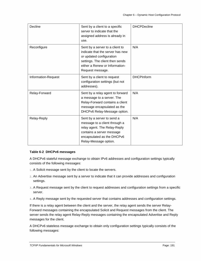
Chapter 6 – Dynamic Host Configuration Protocol
TCP/IP Fundamentals for Microsoft Windows Page: 191
Decline Sent by a client to a specific
server to indicate that the
assigned address is already in
use.
DHCPDecline
Reconfigure Sent by a server to a client to
indicate that the server has new
or updated configuration
settings. The client then sends
either a Renew or Information-
Request message.
N/A
Information-Request Sent by a client to request
configuration settings (but not
addresses).
DHCPInform
Relay-Forward Sent by a relay agent to forward
a message to a server. The
Relay-Forward contains a client
message encapsulated as the
DHCPv6 Relay-Message option.
N/A
Relay-Reply Sent by a server to send a
message to a client through a
relay agent. The Relay-Reply
contains a server message
encapsulated as the DHCPv6
Relay-Message option.
N/A
Table 6-2 DHCPv6 messages
A DHCPv6 stateful message exchange to obtain IPv6 addresses and configuration settings typically
consists of the following messages:
1. A Solicit message sent by the client to locate the servers.
2. An Advertise message sent by a server to indicate that it can provide addresses and configuration
settings.
3. A Request message sent by the client to request addresses and configuration settings from a specific
server.
4. A Reply message sent by the requested server that contains addresses and configuration settings.
If there is a relay agent between the client and the server, the relay agent sends the server Relay-
Forward messages containing the encapsulated Solicit and Request messages from the client. The
server sends the relay agent Relay-Reply messages containing the encapsulated Advertise and Reply
messages for the client.
A DHCPv6 stateless message exchange to obtain only configuration settings typically consists of the
following messages:
Chapter 6 – Dynamic Host Configuration Protocol
TCP/IP Fundamentals for Microsoft Windows Page: 192
1. An Information-Request message sent by the DHCPv6 client to request configuration settings from a
server.
2. A Reply message sent by a server containing the requested configuration settings.
For an IPv6 network that has routers configured to assign stateless address prefixes to IPv6 hosts, the
two-message DHCPv6 exchange can be used to assign DNS servers, DNS domain names, and other
configuration settings that are not included in router advertisement message.
DHCPv6 Support in Windows
Windows Vista and Windows Server 2008 include a DHCPv6 client. The DHCPv6 client attempts
DHCPv6-based configuration depending on the values of the M and O flags in received router
advertisement messages. Therefore, to use DHCPv6, you must configure DHCPv6 servers and relay
agents to service each IPv6 subnet and then configure your IPv6 routers to set these two flags to their
appropriate values. If there are multiple advertising routers for a given subnet, they should be
configured to advertise the same stateless address prefixes and values of the M and O flags. IPv6
hosts running Windows XP or Windows Server 2003 do not include a DHCPv6 client and ignore the
values of the M and O flags in received router advertisements.
You can configure an IPv6 router that is running Windows Vista or Windows Server 2008 to set the M
flag to 1 in router advertisements with the netsh interface ipv6 set interface InterfaceNameOrIndex
managedaddress=enabled command. Similarly, you can set the O flag to 1 in router advertisements
with the netsh interface ipv6 set interface InterfaceNameOrIndex otherstateful=enabled command.
Windows Server 2008 supports DHCPv6 stateful and stateless configuration with the DHCP Server
service and a DHCPv6 relay agent with the Routing and Remote Access service.
Configuring DHCPv6 Scopes and Options
To create a DHCPv6 scope, do the following:
1. In the console tree of the DHCP snap-in, right-click the IPv6 node, and then click New scope.
2. Follow the instructions in the New Scope Wizard.
To configure a DHCPv6 scope option, do the following:
1. In the console tree of the DHCP snap-in, open the IPv6 node, and then open the applicable scope.
2. Right-click Scope Options, and then click Configure Options.
3. In Available Options, select the check box for the first option that you want to configure.
4. Under Data entry, type the information required for this option, and then click OK.
5. Repeat the steps 3-4 for any other options you want to specify.
Figure 6-18 shows an example of the configuration of the DNS Recursive Name Server IPv6 Address
List scope option.
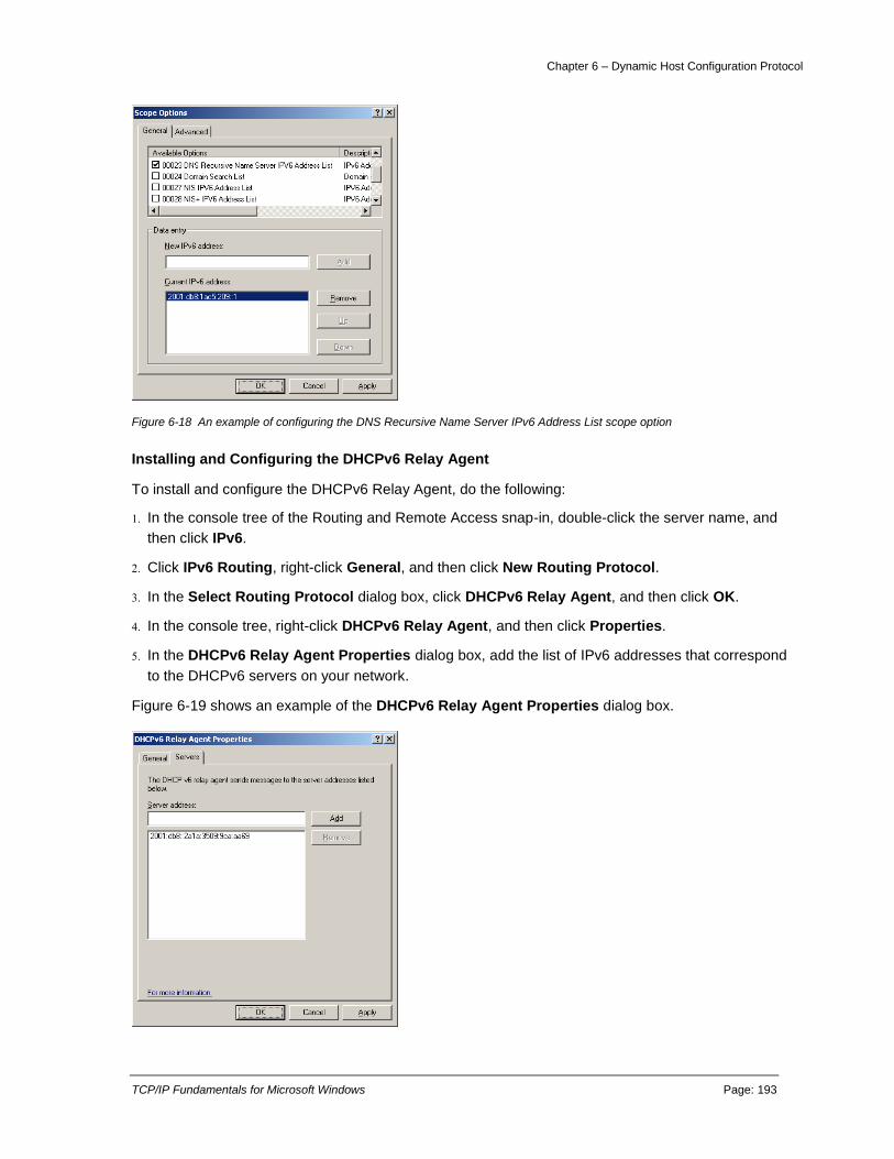
Chapter 6 – Dynamic Host Configuration Protocol
TCP/IP Fundamentals for Microsoft Windows Page: 193
Figure 6-18 An example of configuring the DNS Recursive Name Server IPv6 Address List scope option
Installing and Configuring the DHCPv6 Relay Agent
To install and configure the DHCPv6 Relay Agent, do the following:
1. In the console tree of the Routing and Remote Access snap-in, double-click the server name, and
then click IPv6.
2. Click IPv6 Routing, right-click General, and then click New Routing Protocol.
3. In the Select Routing Protocol dialog box, click DHCPv6 Relay Agent, and then click OK.
4. In the console tree, right-click DHCPv6 Relay Agent, and then click Properties.
5. In the DHCPv6 Relay Agent Properties dialog box, add the list of IPv6 addresses that correspond
to the DHCPv6 servers on your network.
Figure 6-19 shows an example of the DHCPv6 Relay Agent Properties dialog box.

Chapter 6 – Dynamic Host Configuration Protocol
TCP/IP Fundamentals for Microsoft Windows Page: 194
Figure 6-19 An example of the DHCPv6 Relay Agent Properties dialog box
After you have installed the DHCPv6 Relay Agent and configured the list of DHCPv6 servers, you must
enable the DHCPv6 Relay Agent on the appropriate interfaces. To enable the DHCPv6 Relay Agent on
an additional interface, do the following:
1. In the console tree of the Routing and Remote Access snap-in, double-click the server name, and
then click IPv6.
2. Double-click IPv6 Routing, right-click DHCPv6 Relay Agent, and then click New Interface.
3. Click the interface that you want to add, and then click OK.
4. In the DHCPv6 Relay Properties dialog box, on the General tab, verify that the Relay DHCPv6
packets check box is selected.
5. If needed, in Hop-count threshold and Boot threshold (seconds), click the arrows to modify the
thresholds as needed.
6. Click OK.
Figure 6-20 shows an example of the DHCPv6 Relay Properties dialog box for an interface.
Figure 6-20 An example of the DHCPv6 Relay Properties dialog box for an interface

Chapter 6 – Dynamic Host Configuration Protocol
TCP/IP Fundamentals for Microsoft Windows Page: 195
Using the Ipconfig Tool
You use the Ipconfig tool to display a computer’s TCP/IP configuration and to manage an IPv4 address
configuration that was allocated using DHCP.
Verifying the IP Configuration
To display basic information about the TCP/IP configuration of a computer that is running Windows,
type ipconfig at the command prompt. The basic TCP/IP configuration information includes the
following for each interface:
Connection-specific DNS suffix
IP addresses (IPv4 and IPv6)
Subnet mask (for IPv4 addresses)
Default gateway
To display detailed information about the TCP/IP configuration of a computer that is running Windows,
type ipconfig /all at the command prompt.
The detailed TCP/IP configuration information includes the following additional items for the computer:
The host name
The primary DNS suffix
The NetBIOS node type
Whether IP routing is enabled
Whether the WINS proxy is enabled
The DNS suffix search list
The detailed TCP/IP configuration information also includes the following additional items for each
interface:
Description of the network adapter
MAC address of the network adapter
Whether DHCP is enabled
Whether autoconfiguration (APIPA) is enabled
The IPv4 address of the DHCP server that allocated the IPv4 address of this interface
The IPv4 addresses of the primary and secondary WINS servers
For an IPv4 address that was allocated using DHCP, when the lease was obtained and when the lease
expires
Renewing a Lease
To renew a lease on an IPv4 address that was allocated using DHCP, type ipconfig /renew at the
command prompt. The /renew parameter causes the DHCP Client service to send a DHCPRequest

Chapter 6 – Dynamic Host Configuration Protocol
TCP/IP Fundamentals for Microsoft Windows Page: 196
message to the DHCP server to get updated options and a new lease time. If the DHCP server is
unavailable, the client continues to use the current configuration.
Releasing a Lease
To release the current IPv4 address configuration, type ipconfig /release at the command prompt. The
/release parameter causes the DHCP Client service to send a DHCPRelease message to the DHCP
server. This can be useful when the client is moving to a different network and will not need the
previous lease. After you issue this command, the interfaces that previously had IPv4 address
configurations allocated using DHCP are configured with the IPv4 unspecified address of 0.0.0.0, and
TCP/IP communications using that interface stops.
By default, DHCP clients running Windows do not initiate DHCPRelease messages when they shut
down. If a client remains shut down for the length of its lease (and the lease is not renewed), the DHCP
server can assign that client’s IPv4 address to a different client after the lease expires. By not sending a
DHCPRelease message, the client is more likely to receive the same IPv4 address during initialization.
Setting and Displaying the Class ID
To set the user class ID on a computer running Windows, type ipconfig /setclassid Adapter ClassID at
the command prompt, in which Adapter is the name of the interface in Network Connections and
ClassID is the class ID. To remove the class ID from an interface, omit the ClassID parameter.
To display the user class ID, type ipconfig /showclassid Adapter at the command prompt.
Chapter 6 – Dynamic Host Configuration Protocol
TCP/IP Fundamentals for Microsoft Windows Page: 197
Chapter Summary
The chapter includes the following pieces of key information:
DHCP is a TCP/IP standard described in RFCs 2131 and 2132, and it allows TPC/IP hosts to
automatically receive an IPv4 address and other configuration parameters (such as a subnet mask,
default gateway, and others) from a centrally administered DHCP server. Using DHCP eliminates the
administrative and technical support problems associated with users who manually configure their IPv4
address configurations.
DHCP clients exchange a set of messages with a DHCP server to discover the set of DHCP servers,
obtain a set of offered IPv4 address configurations, select a specific IPv4 address configuration, and
receive an acknowledgement. DHCP relay agents facilitate DHCP message exchanges between DHCP
clients and DHCP servers that are located on different subnets.
You can install the DHCP Server service in Windows Server 2003 as an optional networking
component, and you can configure server properties, scopes and superscopes, options, and client
reservations.
You can install and configure the DHCP Relay Agent in Windows Server 2008 and Windows
Server 2003 as a routing protocol component of the Routing and Remote Access service.
Stateless address autoconfiguration for an IPv6 host is done through the router discovery process, in
which IPv6 nodes on a subnet use Router Solicitation and Router Advertisement messages to
automatically configure IPv6 addresses and other configuration options.
Stateful address autoconfiguration for an IPv6 host is done through DHCPv6, based on the M and O
flags in the received Router Advertisement messages. With DHCPv6 stateful operation, both IPv6
address and other settings are assigned by the DHCPv6 server. With DHCPv6 stateless operation, only
IPv6 settings are assigned by the DHCPv6 server.
The DHCP Server service in Windows Server 2008 supports stateful and stateless DHCPv6 operation.
You can install and configure the DHCPv6 Relay Agent in Windows Server 2008 as a routing protocol
component of the Routing and Remote Access service.
You can use the Ipconfig tool to view a computer’s current IP configuration and to manage the IPv4
address configuration that was allocated using DHCP.

Chapter 6 – Dynamic Host Configuration Protocol
TCP/IP Fundamentals for Microsoft Windows Page: 198
Chapter Glossary
address autoconfiguration – The process of automatically configuring IPv6 addresses on an interface.
See also stateless autoconfiguration and stateful autoconfiguration.
BOOTP – See bootstrap protocol (BOOTP).
bootstrap protocol (BOOTP) – A protocol that is defined in RFCs 951 and 1542 and that is used
primarily on TCP/IP networks to configure diskless workstations.
deprecated state – The state of an autoconfigured IPv6 address in which the address is valid but its use
is discouraged for new communication.
DHCP – See Dynamic Host Configuration Protocol (DHCP)
DHCP client – Any network node that supports the ability to communicate with a DHCP server to obtain
a leased IPv4 configuration and related optional parameters information.
DHCP relay agent – An agent program or component that is responsible for relaying DHCP and
BOOTP messages between a DHCP server and a DHCP client. A DHCP relay agent supports
DHCP/BOOTP message relay as defined in RFC 1542. A DHCP relay agent can run on a router or a
host computer.
DHCP server – A computer that offers dynamic configuration of IPv4 addresses and related information
to DHCP-enabled clients.
DHCPv6 stateful – A DHCPv6 operating mode in which a DHCPv6 server assigns stateful addresses to
IPv6 hosts.
DHCPv6 stateless – A DHCPv6 operating mode in which a DHCPv6 server provides stateless
configuration settings but does not assign stateful addresses to IPv6 hosts.
Dynamic Host Configuration Protocol (DHCP) – A TCP/IP standard that offers dynamic leased
configuration of host IPv4 addresses and other configuration parameters to DHCP clients. DHCP
provides safe, reliable, and simple TCP/IP network configuration, prevents address conflicts, and helps
conserve the use of client IPv4 addresses on the network.
Dynamic Host Configuration Protocol for IPv6 (DHCPv6) – A stateful address configuration protocol that
can provide IPv6 hosts with a stateful IPv6 address and other configuration parameters.
exclusion range – A small range of one or more IPv4 addresses within a DHCP scope that are excluded
for allocation to DHCP clients. Exclusion ranges ensure that DHCP servers do not offer specific
addresses within a scope to DHCP clients.
invalid state – The state of an autoconfigured IPv6 address in which it can no longer be used to send or
receive unicast traffic. An IPv6 address enters the invalid state when its valid lifetime expires.
lease – The length of time for which a DHCP client can use a dynamically assigned IPv4 address
configuration. Before the lease time expires, the client must either renew or obtain a new lease with
DHCP.
option – An address configuration parameter that a DHCP server assigns to clients. Most DHCP
options are predefined, based on optional parameters defined in RFC 2132, although vendors or users
can add extended options.

Chapter 6 – Dynamic Host Configuration Protocol
TCP/IP Fundamentals for Microsoft Windows Page: 199
preferred lifetime – The amount of time in which a unicast IPv6 address configured through stateless
address autoconfiguration remains in the preferred state.
preferred state – The state of an autoconfigured IPv6 address for which the address is valid, its
uniqueness has been verified, and it can be used for unlimited communications.
reservation – A specific IPv4 address that is within a scope and that has been permanently reserved for
use by a specific DHCP client. Client reservations are based on a unique client device identifier
(typically its MAC address)
router discovery – An IPv6 Neighbor Discovery process in which a host discovers the routers on an
attached link.
scope – A range of IPv4 addresses that are available to be leased or assigned to DHCP clients by the
DHCP service.
stateful address configuration – The use of a stateful IPv6 address configuration protocol, such as
DHCPv6, to configure IPv6 addresses and configuration parameters.
stateless address configuration – The use of Router Solicitation and Router Advertisement messages to
automatically configure IPv6 addresses and configuration parameters.
superscope – An administrative grouping feature that supports a DHCP server's ability to use more than
scope for a physical network. Each superscope can contain one or more member scopes.
tentative address – A unicast IPv6 address whose uniqueness has not yet been verified.
tentative state – The state of an autoconfigured IPv6 address in which uniqueness has not yet been
verified.
user class – An administrative feature that allows DHCP clients to be grouped logically according to a
shared or common need. For example, you can define a user class and use it to allow similar DHCP
leased configuration for all client computers of a specific type or in a specific building or site location.
valid state – The state of an autoconfigured IPv6 address for which the address can be used for
sending and receiving unicast traffic. The valid state includes both the preferred and deprecated states.
vendor class – An administrative feature that allows DHCP clients to be identified and allocated
addresses and options according to their vendor and hardware configuration type. For example,
assigning a vendor class to a set of printers allows them to be managed as a single unit so they could
all obtain a custom set of DHCP options.

Chapter 6 – Dynamic Host Configuration Protocol
TCP/IP Fundamentals for Microsoft Windows Page: 200

Chapter 7 – Host Name Resolution
TCP/IP Fundamentals for Microsoft Windows Page: 201
Chapter 7 – Host Name Resolution
Abstract
This chapter describes the various mechanisms that Microsoft Windows-based computers use to resolve host names,
such as www.example.com, to their corresponding IP addresses. Network administrators must understand host name
resolution in Windows to troubleshoot issues with host name resolution and to prepare for the complexities of the
Domain Name System (DNS).

Chapter 7 – Host Name Resolution
TCP/IP Fundamentals for Microsoft Windows Page: 202
Chapter Objectives
After completing this chapter, you will be able to:
Define a host name.
Explain how a host name is resolved to an IP address using the Hosts file and the Windows DNS client
resolver cache.
Explain how a host name is resolved to an IP address using a DNS server.
Explain how a host name is resolved to an IP address using the Link-Local Multicast Name Resolution
(LLMNR) protocol.
Explain how a host name is resolved to an IP address using additional Windows-specific methods.
Describe how to modify the Hosts file so that host names are resolved to both Internet Protocol version
4 (IPv4) and Internet Protocol version 6 (IPv6) addresses.
Describe the characteristics of the DNS client resolver cache and how to display and flush the cache
with the Ipconfig tool.

Chapter 7 – Host Name Resolution
TCP/IP Fundamentals for Microsoft Windows Page: 203
TCP/IP Naming Schemes
Before communication can take place, each interface on each TCP/IP node must be assigned a unicast
IP address. A TCP/IP host and its interfaces can also be assigned names. However, the naming
scheme affects the way that a host or interface is referenced in applications. For example:
When using a Windows Sockets application, a user specifies either an IP address or a host name (also
known as a domain name). If the user specifies a host name, TCP/IP for Windows attempts to resolve
the name to an IP (IPv4 or IPv6) address. If the user specifies an IP address, name resolution is not
necessary.
When using a network basic input/output system (NetBIOS) application, a user specifies a computer
name, which the application converts into a 16-character NetBIOS name. TCP/IP for Windows attempts
to resolve the NetBIOS name to an IPv4 address.
With NetBIOS applications, users must always specify the NetBIOS name and not the IPv4 address.
Windows Sockets applications allow users to specify the destination host by its host name or IP
address.
Host Names Defined
A host name is an alias assigned to identify a TCP/IP host or its interfaces. Host names are used in all
TCP/IP environments. The following describes the attributes of a host name:
The host name does not have to match the NetBIOS computer name, and a host name can contain as
many as 255 characters.
Multiple host names can be assigned to the same host.
Host names are easier to remember than IP addresses.
A user can specify host name instead of an IP address when using Windows Sockets applications,
such as the Ping tool or Internet Explorer.
A host name should correspond to an IP address mapping that is stored either in the local Hosts file or
in a database on a DNS server. TCP/IP for Windows also use NetBIOS name resolution methods for
host names.
The Hostname tool displays the computer name of your Windows–based computer, as configured from
the Computer Name tab of the System item of Control Panel.

Chapter 7 – Host Name Resolution
TCP/IP Fundamentals for Microsoft Windows Page: 204
Host Name Resolution Process
Host name resolution is the process of resolving a host name to an IP address before the source host
sends the initial IP packet. Table 7-1 lists the standard methods of host name resolution for TCP/IP for
Windows.
Resolution Method Description
Local host name The configured host name for the computer as
displayed in the output of the Hostname tool. This
name is compared to the destination host name.
Hosts file A local text file in the same format as the 4.3 Berkeley
Software Distribution (BSD) UNIX \etc\hosts file. This
file maps host names to IP addresses. For TCP/IP for
Windows, the contents of the Hosts file are loaded into
the DNS client resolver cache. For more information,
see "The DNS Client Resolver Cache" in this chapter.
DNS server A server that maintains a database of IP address-to-
host name mappings and has the ability to query other
DNS servers for mappings that it does not contain.
Table 7-1 Standard Methods of Host Name Resolution
Table 7-2 lists the additional methods used by TCP/IP for Windows to resolve host names.

Chapter 7 – Host Name Resolution
TCP/IP Fundamentals for Microsoft Windows Page: 205
Resolution Method Description
DNS client resolver cache A random access memory (RAM)-based table of the
entries listed in the local Hosts file and the names that
were attempted for resolution by using a DNS server.
Link-local Multicast Name Resolution (LLMNR) A simple request-reply protocol to resolve names of
computers on the local subnet in the absence of a
DNS server. Only computers running Windows Vista
or Windows Server 2008 support LLMNR.
NetBIOS name cache A RAM-based table of recently resolved NetBIOS
names and their associated IPv4 addresses.
NetBIOS name server (NBNS) A server that resolves NetBIOS names to IPv4
addresses, as specified by Requests for Comments
(RFCs) 1001 and 1002. The Microsoft implementation
of an NBNS is a Windows Internet Name Service
(WINS) server.
Local broadcast Up to three NetBIOS Name Query Request messages
are broadcast on the local subnet to resolve the IPv4
address of a specified NetBIOS name.
Lmhosts file A local text file that maps NetBIOS names to IPv4
addresses for NetBIOS processes running on
computers located on remote subnets.
Table 7-2 Windows-Specific Methods of Host Name Resolution
Resolving Names with a Hosts File
TCP/IP for Windows does not search the Hosts file directly when performing name resolution. Rather,
the entries in the Hosts file are automatically loaded into the DNS client resolver cache. Therefore, the
process of resolving a host name with the Hosts file for a Windows-based computer is the following:
1. Host name resolution begins when a user uses a Windows Sockets application and specifies the host
name assigned to the destination host. Windows checks whether the host name matches the local
host name.
If the host name is the same as the local host name, the host name is resolved to an IP address that
is assigned to the local host, and the name resolution process stops.
2. If the host name is not the same as the local host name, Windows searches the DNS client resolver
cache for an entry containing the host name.
If Windows does not find the host name in the DNS client resolver cache and no other name
resolution methods are configured or enabled (such as DNS or NetBIOS name resolution methods),
the name resolution process stops, and an error condition is indicated to the Windows Sockets
application, which then typically displays an error message to the user.
If Windows finds the host name in the DNS client resolver cache, the host name is resolved to the IP
address that corresponds to the entry in the cache.
3. After the host name is resolved to a destination IP address, Windows forwards the packet to the next-
hop IP address for the destination (either the destination or a neighboring router).

Chapter 7 – Host Name Resolution
TCP/IP Fundamentals for Microsoft Windows Page: 206
Unlike the Lmhosts file, which is used for remote NetBIOS-based hosts and IPv4 addresses only, the
Hosts file maps host names of both neighboring and remote hosts to their IPv4 or IPv6 addresses.
Resolving Names with LLMNR
LLMNR is a new protocol defined in RFC 4795 that provides an additional method to resolve the names
of neighboring computers. LLMNR uses a simple exchange of request and reply messages to resolve
computer names to IPv4 or IPv6 addresses.
LLMNR allows name resolution on networks where a DNS server is not present or practical. A good
example is the temporary subnet formed by a group of computers that form an ad hoc IEEE 802.11
wireless network. With LLMNR, hosts in the ad hoc wireless network can resolve each other’s computer
names without having to configure one of the computers as a DNS server and the other computers with
the IP address of the computer acting as the DNS server.
For LLMNR messages sent over IPv4, a querying host sends a LLMNR Name Query Request message
to the IPv4 multicast address of 224.0.0.252. For LLMNR messages sent over IPv6, a querying host (a
requestor) sends an LLMNR Name Query Request message to the IPv6 multicast address of
FF02::1:3.
The typical LLMNR message exchange for a name query consists of a multicast query and, if a host on
the subnet is authoritative for the requested name, a unicast response to the requestor.
Resolving Names with a DNS Server
DNS is a distributed, hierarchical naming system that is used on the Internet and in most intranets to
resolve fully qualified domain names (FQDNs) to IP addresses. An example of an FQDN is
www.microsoft.com. A DNS server typically maintains information about a portion of the DNS
namespace, such as all the names ending with wcoast.example.com, and resolves DNS name queries
for DNS client computers, either itself or by querying other DNS servers. Computers running Windows
can act as DNS clients, and a computer running Windows Server 2008 or Windows Server 2003 can
act as a DNS server to resolve names on behalf of a DNS client or other DNS servers.
If TCP/IP for Windows is configured with the IP address of a DNS server, the name resolution process
is as follows:
1. When a user uses a Windows Sockets application and specifies an FQDN for the destination host
and the FQDN does not match the local host name or any entries in the DNS client resolver cache,
the DNS client component of TCP/IP for Windows constructs and sends a DNS Name Query
Request message to the DNS server.
2. The DNS server determines whether a mapping for the name to an IP address is stored either locally
or on another DNS server. Whether or not a mapping is found, the DNS server sends back a DNS
Name Query Response message to the DNS client.
If the DNS server does not respond to the request, the DNS client sends additional DNS Name
Query Request messages. If the DNS server does not respond to any of the attempts, no other DNS
servers are configured, and NetBIOS over TCP/IP is not enabled, an error condition is indicated to
the Windows Sockets application, which then typically displays an error message to the user.
3. After the FQDN is resolved to a destination IP address, Windows forwards the packet to the next-hop
IP address for the destination (either the destination or a neighboring router).

Chapter 7 – Host Name Resolution
TCP/IP Fundamentals for Microsoft Windows Page: 207
Windows Methods of Resolving Host Names
If NetBIOS over TCP/IP is enabled, Windows by default attempts to resolve host names using NetBIOS
methods when standard methods fail. NetBIOS name resolution methods include the NetBIOS name
cache, configured WINS servers, NetBIOS broadcasts, and the Lmhosts file.
When an application uses Windows Sockets and either the application or a user specifies a host name,
TCP/IP for Windows attempts to resolve the name in the following order when NetBIOS over TCP/IP is
enabled:
1. Windows checks whether the host name is the same as the local host name.
2. If the host name and local host name are not the same, Windows searches the DNS client resolver
cache.
3. If the host name cannot be resolved using the DNS client resolver cache, Windows sends DNS
Name Query Request messages to its configured DNS servers.
4. If the host name is a single-label name (such as server1) and cannot be resolved using the
configured DNS servers, computers running Windows Vista or Windows Server 2008 send up to two
sets of multicast LLMNR query messages over both IPv4 and IPv6.
5. If the host name is a single-label name and is still not resolved, Windows converts the host name to a
NetBIOS name and checks its local NetBIOS name cache.
Windows creates the 16-byte NetBIOS name by converting the host name, which must be less than
16 bytes long, to uppercase and padding it with space characters if needed to create the first 15
bytes of the NetBIOS name. Then, Windows adds 0x00 as the last byte. Every Windows-based
computer running the Workstation service registers its computer name with a 0x00 as the last byte.
Therefore, the NetBIOS form of the host name will typically resolve to the IPv4 address of the
computer that has a NetBIOS computer name that matches the host name.
If the host name is 16 characters or longer or an FQDN, Windows does not convert it to a NetBIOS
name or try to resolve the host name using NetBIOS techniques.
6. If Windows cannot find the NetBIOS name in the NetBIOS name cache, Windows contacts its
configured WINS servers.
7. If Windows cannot query the WINS servers to resolve the NetBIOS name that corresponds to the
host name, Windows broadcasts as many as three NetBIOS Name Query Request messages on the
directly attached subnet.
8. If Windows cannot use NetBIOS to resolve the NetBIOS name that corresponds to the host name,
Windows searches the local Lmhosts file.
The name resolution process stops when Windows finds the first IP address for the name. If Windows
cannot resolve the host name using any of these methods, name resolution fails, and the only way to
communicate with the destination host is to specify either its IP address or another name associated
with the host that Windows can resolve to an IP address.

Chapter 7 – Host Name Resolution
TCP/IP Fundamentals for Microsoft Windows Page: 208
The Hosts File
The Hosts file is a common way to resolve a host name to an IP address through a locally stored text
file that contains IP-address-to-host-name mappings. On most UNIX-based computers, this file is
/etc/hosts. On Windows-based computers, this file is the Hosts file in the
systemroot\System32\Drivers\Etc folder.
The following describes the attributes of the Hosts file for Windows:
A single entry consists of an IP (IPv4 or IPv6) address and one or more host names.
The Hosts file is dynamically loaded into the DNS client resolver cache, which Windows Sockets
applications use to resolve a host name to an IP address on both local and remote subnets.
When you create entries in the Hosts file and save it, its contents are automatically loaded into the DNS
client resolver cache.
The Hosts file contains a default entry for the host name localhost.
The Hosts file can be edited with any text editor.
Each host name is limited to 255 characters.
Entries in the Hosts file for Windows–based computers are not case sensitive.
The advantage of using a Hosts file is that users can customize it for themselves. Each user can create
whatever entries they want, including easy-to-remember nicknames for frequently accessed resources.
However, the individual maintenance required for the Hosts file does not scale well to storing large
numbers of FQDN mappings or reflecting changes to IP addresses for servers and network resources.
The solution for the large-scale storage and maintenance of FQDN mappings is DNS. The solution for
the maintenance of FQDN mappings for changing IP addresses is DNS dynamic update.
An entry in the Hosts file has the following format:
Address Names
The Address portion of the entry is either an IPv4 or IPv6 unicast address. The Names portion of the
entry is one or more names (nicknames or FQDNs) separated by at least one space character. One or
multiple space or tab characters must separate the address from the first name.
IPv4 Entries
For IPv4 entries, the address in the Hosts file entry is a unicast IPv4 address expressed in dotted
decimal notation. For example, the following Hosts file contains IPv4 entries:
#
# Table of IP addresses and host names
#
127.0.0.1 localhost
131.107.34.1 router
172.30.45.121 server1.central.example.com s1
In this example, you can refer to the server at the IPv4 address 172.30.45.121 by its FQDN
(server1.central.example.com) or by its nickname (s1). This example assumes that the IP address for
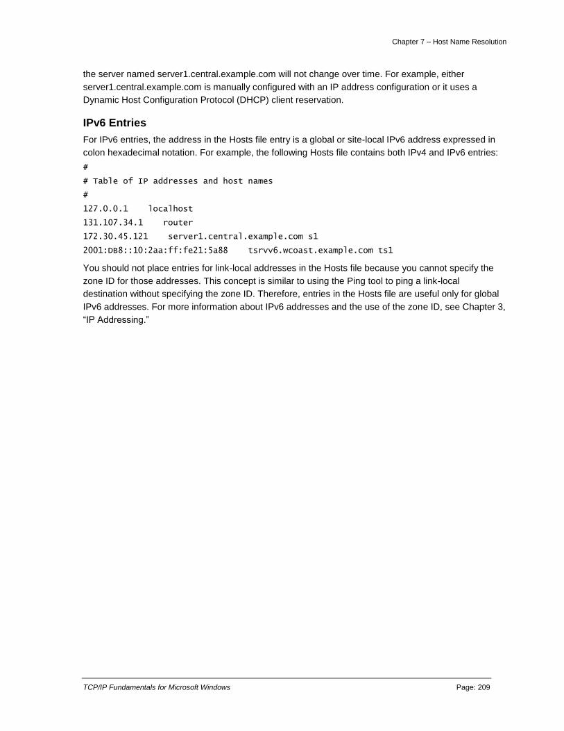
Chapter 7 – Host Name Resolution
TCP/IP Fundamentals for Microsoft Windows Page: 209
the server named server1.central.example.com will not change over time. For example, either
server1.central.example.com is manually configured with an IP address configuration or it uses a
Dynamic Host Configuration Protocol (DHCP) client reservation.
IPv6 Entries
For IPv6 entries, the address in the Hosts file entry is a global or site-local IPv6 address expressed in
colon hexadecimal notation. For example, the following Hosts file contains both IPv4 and IPv6 entries:
#
# Table of IP addresses and host names
#
127.0.0.1 localhost
131.107.34.1 router
172.30.45.121 server1.central.example.com s1
2001:DB8::10:2aa:ff:fe21:5a88 tsrvv6.wcoast.example.com ts1
You should not place entries for link-local addresses in the Hosts file because you cannot specify the
zone ID for those addresses. This concept is similar to using the Ping tool to ping a link-local
destination without specifying the zone ID. Therefore, entries in the Hosts file are useful only for global
IPv6 addresses. For more information about IPv6 addresses and the use of the zone ID, see Chapter 3,
“IP Addressing.”

Chapter 7 – Host Name Resolution
TCP/IP Fundamentals for Microsoft Windows Page: 210
The DNS Client Resolver Cache
The DNS client resolver cache is a RAM-based table that contains both the entries in the Hosts file and
the host names that Windows has tried to resolve through DNS. The DNS client resolver cache stores
entries for both successful and unsuccessful DNS name resolutions. A name that was queried but was
not successfully resolved is known as a negative cache entry.
The following list describes the attributes of the DNS client resolver cache:
It is built dynamically from the Hosts file and from DNS queries.
Entries obtained from DNS queries are kept only for a period of time known as the Time to Live (TTL),
which is set by the DNS server that has the name-to-IP address mapping stored in a local database.
Entries obtained from the Hosts file do not have a TTL and are kept until the entry is removed from the
Hosts file.
You can use the ipconfig /displaydns command to view the contents of the DNS client resolver cache.
You can use the ipconfig /flushdns command to flush and refresh the DNS client resolver cache with
just the entries in the Hosts file.
The following is an example display of the ipconfig /displaydns command:
C:\>ipconfig /displaydns
Windows IP Configuration
localhost.
------------------------------------------------------
Record Name . . . . . : localhost
Record Type . . . . . : 1
Time To Live . . . . : 31165698
Data Length . . . . . : 4
Section . . . . . . . : Answer
A (Host) Record . . . : 127.0.0.1
dc7.corp.example.com.
------------------------------------------------------
Record Name . . . . . : dc7.corp.example.com
Record Type . . . . . : 1
Time To Live . . . . : 852
Data Length . . . . . : 4
Section . . . . . . . : Answer
A (Host) Record . . . : 157.60.23.170

Chapter 7 – Host Name Resolution
TCP/IP Fundamentals for Microsoft Windows Page: 211
1.0.0.127.in-addr.arpa.
------------------------------------------------------
Record Name . . . . . : 1.0.0.127.in-addr.arpa
Record Type . . . . . : 12
Time To Live . . . . : 31165698
Data Length . . . . . : 4
Section . . . . . . . : Answer
PTR Record . . . . . : localhost
mailsrv15.corp.example.com.
------------------------------------------------------
Record Name . . . . . : mailsrv15.corp.example.com
Record Type . . . . . : 1
Time To Live . . . . : 2344
Data Length . . . . . : 4
Section . . . . . . . : Answer
A (Host) Record . . . : 157.54.16.83

Chapter 7 – Host Name Resolution
TCP/IP Fundamentals for Microsoft Windows Page: 212
Chapter Summary
The chapter includes the following pieces of key information:
Window Sockets applications use host names or IP addresses when specifying a destination. Host
names must be resolved to an IP address before communication with the destination can begin.
The standard methods of host name resolution include checking the local host name, checking the local
Hosts file, and querying DNS servers. Windows-based hosts also check the DNS client resolver cache,
which contains the entries in the Hosts file.
LLMNR uses multicast query and unicast reply messages to resolve single-label names on a subnet.
Windows-based hosts on which NetBIOS over TCP/IP is enabled also use NetBIOS methods to attempt
to resolve a host name to an IPv4 address.
The Hosts file on a Windows-based computer is stored in the systemroot\System32\Drivers\Etc folder
and can include entries that map IPv4 or IPv6 addresses to host names.
The Hosts file is dynamically loaded into the RAM-based DNS client resolver cache, which also
contains the results of recent DNS name queries.

Chapter 7 – Host Name Resolution
TCP/IP Fundamentals for Microsoft Windows Page: 213
Chapter Glossary
DNS – See Domain Name System (DNS).
DNS client resolver cache – A RAM-based table that contains both the entries in the Hosts file and the
results of recent DNS name queries.
DNS server – A server that maintains a database of mappings of DNS domain names to various types
of data, such as IP addresses.
Domain Name System (DNS) – A hierarchical, distributed database that contains mappings of DNS
domain names to various types of data, such as IP addresses. DNS enables the specification of
computers and services by user-friendly names, and it also enables the discovery of other information
stored in the database.
Host name – The name of a computer or device on a network. Users specify computers on the network
by their host names. To find another computer, its host name must either appear in the Hosts file or be
known by a DNS server. For most Windows-based computers, the host name and the computer name
are the same.
Host name resolution – The process of resolving a host name to a destination IP address.
Hosts file – A local text file in the same format as the 4.3 BSD UNIX /etc/hosts file. This file maps host
names to IP addresses, and it is stored in the systemroot\System32\Drivers\Etc folder.
Link-local Multicast Name Resolution (LLMNR) – A simple, multicast-based, request-reply protocol that
can resolve single-label host names to IPv4 or IPv6 addresses. LLMNR can be used in the absence of
DNS servers and NetBIOS over TCP/IP.
LLMNR – See Link-local Multicast Name Resolution (LLMNR).
Lmhosts file – A local text file that maps NetBIOS names to IP addresses for hosts that are located on
remote subnets. For Windows-based computers, this file is stored in the
systemroot\System32\Drivers\Etc folder.
negative cache entries – Host names added into the DNS client resolver cache that were queried but
that could not be resolved.
NBNS – See NetBIOS name server (NBNS).
NetBIOS name - A 16-byte name of a process using NetBIOS.
NetBIOS name cache – A dynamically maintained table that resides on a NetBIOS-enabled host and
that stores recently resolved NetBIOS names and their associated IPv4 addresses.
NetBIOS name resolution – The process of resolving a NetBIOS name to an IPv4 address.
NetBIOS name server (NBNS) – A server that stores NetBIOS name to IPv4 address mappings and
resolves NetBIOS names for NetBIOS-enabled hosts. WINS is the Microsoft implementation of a
NetBIOS name server.
Windows Internet Name Service (WINS) – The Microsoft implementation of a NetBIOS name server.
WINS – See Windows Internet Name Service (WINS).

Chapter 7 – Host Name Resolution
TCP/IP Fundamentals for Microsoft Windows Page: 214

Chapter 8 – Domain Name System Overview
TCP/IP Fundamentals for Microsoft Windows Page: 215
Chapter 8 – Domain Name System Overview
Abstract
This chapter describes the details of the Domain Name System (DNS) and its use for private intranets and the Internet.
DNS is required to provide name resolution for domain names such as www.example.com for all types of network
applications from Internet browsers to Active Directory. A network administrator's understanding of DNS names,
domains, zones, name server roles, and replication is vital to the configuration and maintenance of a properly
functioning private intranet and the Internet.

Chapter 8 – Domain Name System Overview
TCP/IP Fundamentals for Microsoft Windows Page: 216
Chapter Objectives
After completing this chapter you will be able to:
Define the components of DNS.
Describe the structure and architecture of DNS as it is used on the Internet.
Define the difference between domains and zones.
Define recursive and iterative queries and how DNS forward and reverse lookups work.
Define the various roles of DNS servers.
Describe the common types of DNS resource records.
Describe the different types of zone transfers.
Define DNS dynamic update.

Chapter 8 – Domain Name System Overview
TCP/IP Fundamentals for Microsoft Windows Page: 217
The Domain Name System
The initial solution for name resolution on the Internet was a file named Hosts.txt that was used on the
now obsolete Advanced Research Projects Agency network (ARPANET), the predecessor of the
modern day Internet. When the number of hosts on the ARPANET was small, the Hosts.txt file was
easy to manage because it consisted of unstructured names and their corresponding IPv4 addresses.
Computers on the ARPANET periodically downloaded Hosts.txt from a central location and used it for
local name resolution. As the ARPANET grew into the Internet, the number of hosts began to increase
dramatically and the centralized administration and manual distribution of a text file containing the
names for computers on the Internet became unwieldy.
The replacement for the Hosts.txt file needed to be distributed, to allow for a hierarchical name space,
and require minimal administrative overhead. The original design goal for DNS was to replace the
existing cumbersome, centrally administered text file with a lightweight, distributed database that would
allow for a hierarchical name space, delegation and distribution of administration, extensible data types,
virtually unlimited database size, and reasonable performance.
DNS defines a namespace and a protocol for name resolution and database replication:
The DNS namespace is based on a hierarchical and logical tree structure.
The DNS protocol defines a set of messages sent over either User Datagram Protocol (UDP) port 53 or
Transmission Control Protocol (TCP) port 53. Hosts that originate DNS queries send name resolution
queries to servers over UDP first because it’s faster. These hosts, known as DNS clients, resort to TCP
only if the returned data is truncated. Hosts that store portions of the DNS database, known as DNS
servers, use TCP when replicating database information.
Historically, the most popular implementation of the DNS protocol is Berkeley Internet Name Domain
(BIND), which was originally developed at the University of California at Berkeley for the 4.3 Berkeley
Software Distribution release of the UNIX operating system.
DNS Components
Requests for Comments (RFCs) 974, 1034, and 1035 define the primary specifications for DNS. From
RFC 1034, DNS comprises the following three components:
1. The domain namespace and resource records
DNS defines a specification for a structured namespace as an inverted tree in which each node and
leaf of the tree names a set of information.
Resource records are records in the DNS database that can be used to configure the DNS database
server (such as the Start of Authority [SOA] record) or to contain information of different types to
process client queries (such as Address [A] records or Mail Exchanger [MX] records). Typical
resource records contain resources by name and their IP addresses. Name queries to DNS database
servers are attempts to extract information of a certain type from the namespace. The name query
requests a name of interest and a specific type of record. For example, a name query would provide
a host name and ask for the corresponding IPv4 or IPv6 address.
2. Name servers
Chapter 8 – Domain Name System Overview
TCP/IP Fundamentals for Microsoft Windows Page: 218
Name servers store resource records and information about the domain tree structure and attempt to
resolve received client queries. DNS database servers, hereafter referred to as name servers or DNS
servers, either contain the requested information in their resource records or have pointer records to
other name servers that can help resolve the client query. If the name server contains the resource
records for a given part of the namespace, the server is said to be authoritative for that part of the
namespace. Authoritative information is organized into units called zones.
3. Resolvers
Resolvers are programs that run on DNS clients and DNS servers and that create queries to extract
information from name servers. A DNS client uses a resolver to create a DNS name query. A DNS
server uses a resolver to contact other DNS servers to resolve a name on a DNS client's behalf.
Resolvers are usually built into utility programs or are accessible through library functions, such as
the Windows Sockets getaddrinfo() or gethostbyname() functions.
DNS Names
DNS names have a very specific structure, which identifies the location of the name in the DNS
namespace. A fully qualified domain name (FQDN) is a DNS domain name that has been constructed
from its location relative to the root of the namespace (known as the root domain). FQDNs have the
following attributes:
FQDNs consist of the series of names from the name of the host or computer to the root domain.
A period character separates each name.
Each FQDN ends with the period character, which indicates the root domain.
Each name within the FQDN can be no more than 63 characters long.
The entire FQDN can be no more than 255 characters long.
FQDNs are not case-sensitive.
RFC 1034 requires the names that make up a FQDN to use only the characters a-z, A-Z, 0-9, and the
dash or minus sign (-). RFC 2181 allows additional characters and is supported by the DNS Server
service in Microsoft Windows Server 2003 operating systems.
Domains and Subdomains
The DNS namespace is in the form of a logical inverted tree structure. Each branch point (or node) in
the tree is given a name that is no more than 63 characters long. Each node of the tree is a portion of
the namespace called a domain. A domain is a branch of the tree and can occur at any point in the tree
structure. Domains can be further partitioned at node points within the domain into subdomains for the
purposes of administration or load balancing. The domain name identifies the domain's position in the
DNS hierarchy. The FQDN identifies the domain relative to the root. You create domain names and
FQDNs by combining the names of the nodes from the designated domain node back to the root and
separating each node with a period (.). The root of the tree has the special reserved name of "" (null),
which you indicate by placing a final period at the end of the domain name (such as
www.sales.example.com.). Domains and subdomains are grouped into zones to allow for distributed
administration of the DNS namespace.
Figure 8-1 shows the DNS namespace as it exists for the Internet.

Chapter 8 – Domain Name System Overview
TCP/IP Fundamentals for Microsoft Windows Page: 219
Figure 8-1 The DNS namespace
Figure 8-1 shows a few of the top-level domains and example hosts in the "microsoft.com." domain. A
trailing period designates a domain name of a host relative to the root domain. To connect to that host,
a user would specify the name "www.microsoft.com." If the user does not specify the final period, the
DNS resolver automatically adds it to the specified name. Individual organizations manage second-level
domains (subdomains of the top level domains) and their name servers. For example, Microsoft
manages the "microsoft.com." domain.
DNS Servers and the Internet
Domains define different levels of authority in a hierarchical structure. The top of the hierarchy is called
the root domain. The DNS namespace on the Internet, as shown in Figure 8-1, has the following
structure:
Root domain
Top-level domains
Second-level domains
The root domain uses a null label, which you write as a single period (.). In the United States, the
Internet Assigned Names Authority (IANA) manages several root domain name servers.
The next level in the hierarchy is divided into a series of nodes called the top-level domains. The top-
level domains are assigned by organization type and by country/region. Some of the more common top-
level domains are the following:
com – Commercial organizations in the United States (for example, microsoft.com for the Microsoft
Corporation).

Chapter 8 – Domain Name System Overview
TCP/IP Fundamentals for Microsoft Windows Page: 220
edu – Educational organizations in the United States.
gov – United States governmental organizations.
int – International organizations.
mil – United States military organizations.
net - Networking organizations.
org – Noncommercial organizations.
xx – Two-letter country code names that follow the International Standard 3166. For example, “.fr” is the
country code for France.
arpa – Used to store information for DNS reverse queries.
Each top-level domain has name servers that IANA administers. Top-level domains can contain
second-level domains and hosts.
Second-level domains contain the domains and names for organizations and countries/regions. The
names in second-level domains are administered by the organization or country/region either directly
(by placing its own DNS server on the Internet) or by using an Internet service provider (ISP) who
manages the names for an organization or country/region on its customer's behalf.
Zones
A zone is a contiguous portion of a domain of the DNS namespace whose database records exist and
are managed in a particular DNS database file stored on one or multiple DNS servers. You can
configure a single DNS server to manage one or multiple zones. Each zone is anchored at a specific
domain node, referred to as the zone's root domain. Zone files do not necessarily contain the complete
branch (that is, all subdomains) under the zone's root domain. For example, you can partition a domain
into several subdomains, which are controlled by separate DNS servers. You might break up domains
across multiple zone files if you want to distribute management of the domain across different groups or
make data replication more efficient.
Figure 8-2 shows the difference between domains and zones.

Chapter 8 – Domain Name System Overview
TCP/IP Fundamentals for Microsoft Windows Page: 221
Figure 8-2 Domains and zones
In the example, "microsoft.com" is a domain (the entire branch of the DNS namespace that starts with
the microsoft.com. node), but the entire domain is not controlled by one zone file. Part of the domain is
in a zone for "microsoft.com." and part of the domain is in a zone for the "dev.microsoft.com." domain.
These zones correspond to different DNS database files that can reside on the same or different DNS
servers.

Chapter 8 – Domain Name System Overview
TCP/IP Fundamentals for Microsoft Windows Page: 222
Name Resolution
The two types of queries that a DNS resolver (either a DNS client or another DNS server) can make to
a DNS server are the following:
Recursive queries
In a recursive query, the queried name server is requested to respond with the requested data or
with an error stating that data of the requested type or the specified domain name does not exist.
The name server cannot just refer the DNS resolver to a different name server. A DNS client
typically sends this type of query.
Iterative queries
In an iterative query, the queried name server can return the best answer it currently has back to
the DNS resolver. The best answer might be the resolved name or a referral to another name
server that is closer to fulfilling the DNS client's original request. DNS servers typically send
iterative queries to query other DNS servers.
DNS Name Resolution Example
To show how recursive and iterative queries are used for common DNS name resolutions, consider a
computer running Windows Vista, Windows XP, Windows Server 2008, or Windows Server 2003
connected to the Internet. A user types http://www.example.com in the Address field of their
Internet browser. When the user presses the ENTER key, the browser makes a Windows Sockets
function call, either gethostbyname() or getaddrinfo(), to resolve the name http://www.example.com
to an IP address. For the DNS portion of the Windows host name resolution process, the following
occurs:
1. The DNS resolver on the DNS client sends a recursive query to its configured DNS server,
requesting the IP address corresponding to the name "www.example.com". The DNS server for that
client is responsible for resolving the name and cannot refer the DNS client to another DNS server.
2. The DNS server that received the initial recursive query checks its zones and finds no zones
corresponding to the requested domain name; the DNS server is not authoritative for the
example.com domain. Because the DNS server has no information about the IP addresses of DNS
servers that are authoritative for example.com. or com., it sends an iterative query for
www.example.com. to a root name server.
3. The root name server is authoritative for the root domain and has information about name servers
that are authoritative for top-level domain names. It is not authoritative for the example.com. domain.
Therefore, the root name server replies with the IP address of a name server for the com. top-level
domain.
4. The DNS server of the DNS client sends an iterative query for www.example.com. to the name
server that is authoritative for the com. top-level domain.
5. The com. name server is authoritative for the com. domain and has information about the IP
addresses of name servers that are authoritative for second-level domain names of the com. domain.
It is not authoritative for the example.com. domain. Therefore, the com. name server replies with the
IP address of the name server that is authoritative for the example.com. domain.

Chapter 8 – Domain Name System Overview
TCP/IP Fundamentals for Microsoft Windows Page: 223
6. The DNS server of the DNS client sends an iterative query for www.example.com. to the name
server that is authoritative for the example.com. domain.
7. The example.com. name server replies with the IP address corresponding to the FQDN
www.example.com.
8. The DNS server of the DNS client sends the IP address of www.example.com to the DNS client.
Figure 8-3 shows this process.
Figure 8-3 Example of recursive and iterative queries in DNS name resolution
All DNS queries are DNS Name Query Request messages. All DNS replies are DNS Name Query
Response messages.
In practice, DNS servers cache the results of queries on an ongoing basis. If a DNS server finds an
entry matching the current request in its cache, it does not send an iterative DNS query. This example
assumes that no cache entries were in any of the DNS servers to prevent the sending of the iterative
name queries.
Forward lookups are queries in which a DNS client attempts to resolve an FQDN to its corresponding IP
address. Zones that contain FQDN-to-IP address mappings are known as forward lookup zones.
Reverse Queries
In a reverse query, instead of supplying a name and asking for an IP address, the DNS client provides
the IP address and requests the corresponding host name. Reverse queries are also known as reverse
lookups, and zones that contain IP address-to-FQDN mappings are known as reverse lookup zones.

Chapter 8 – Domain Name System Overview
TCP/IP Fundamentals for Microsoft Windows Page: 224
Because you cannot derive the IP address from a domain name in the DNS namespace, only a
thorough search of all domains could guarantee a correct answer. To prevent an exhaustive search of
all domains for a reverse query, reverse name domains and pointer (PTR) resource records were
created.
An example of an application that uses reverse queries is the Tracert tool, which by default uses
reverse queries to display the names of the routers in a routing path. If you are going to use reverse
queries, you must create reverse lookup zones and PTR records when you administer a DNS server so
that reverse queries can be satisfied.
Reverse Queries for IPv4 Addresses
To support reverse lookups for IPv4 addresses, a special domain named in-addr.arpa. was created.
Nodes in the in-addr.arpa domain are named after the numbers in the dotted decimal representation of
IPv4 addresses. But because IPv4 addresses get more specific from left to right and domain names get
more specific from right to left, the order of IPv4 address octets must be reversed when building the in-
addr.arpa domain name corresponding to the IPv4 address. For example, for the generalized IPv4
address w.x.y.z, the corresponding reverse query name is z.y.x.w.in-addr.arpa. IANA delegates
responsibility for administering the reverse query namespace below the in-addr.arpa domain to
organizations as they are assigned IPv4 address prefixes.
Figure 8-4 shows an example of the reverse lookup portion of the DNS namespace.
Figure 8-4 An example of a reverse lookup portion of the DNS namespace
Within the in-addr.arpa domain, special pointer (PTR) resource records are added to associate the IPv4
addresses to their corresponding host names. To find a host name for the IPv4 address 157.54.200.2, a
DNS client sends a DNS query for a PTR record for the name 2.200.54.157.in-addr.arpa. Reverse
queries use the same name resolution process previously described for forward lookups (a combination

Chapter 8 – Domain Name System Overview
TCP/IP Fundamentals for Microsoft Windows Page: 225
of recursive and iterative queries). The DNS server finds the PTR record that contains the FQDN that
corresponds to the IPv4 address 157.54.200.2 and sends that FQDN back to the DNS client.
Reverse Queries for IPv6 Addresses
IPv6 reverse lookups use the ip6.arpa. domain. To create the domains for reverse queries, each
hexadecimal digit in the fully expressed 32-digit IPv6 address becomes a separate level in the reverse
domain hierarchy in inverse order.
For example, the reverse lookup domain name for the address 2001:db8::1:2aa:ff:fe3f:2a1c (fully
expressed as 2001:0db8:0000:0001:02aa:00ff:fe3f:2a1c) is
c.1.a.2.f.3.e.f.f.f.0.0.a.a.2.0.1.0.0.0.0.0.0.0.8.b.d.0.1.0.0.2.ip6.arpa.
Just as in IPv4 addresses, PTR records in the reverse IPv6 domain map IPv6 addresses to FQDNs.
Caching and TTL
For each resolved query (either recursive or iterative), the DNS resolver caches the returned
information for a time that is specified in each resource record in the DNS response. This is known as
positive caching. The amount of time in seconds to store the record data in the cache is referred to as
the Time To Live (TTL). The network administrator of the zone that contains the record decides on the
default TTL for the data in the zone. Smaller TTL values help ensure that data about the domain is
more consistent across the network if the zone data changes often. However, this practice also
increases the load on name servers because positive cache entries time out more quickly.
After a DNS resolver caches data, it must start counting down from the received TTL so that it will know
when to remove the data from its cache. For queries that can be satisfied by this cached data, the TTL
that is returned is the current amount of time left before the data is flushed from the DNS cache. DNS
client resolvers also have data caches and honor the TTL value so that they know when to remove the
data.
The DNS Client service in Windows Vista, Windows XP, Windows Server 2008 and Windows
Server 2003 and the DNS Server service in Windows Server 2008 and Windows Server 2003 support
positive caching.
Negative Caching
As originally defined in RFC 1034, negative caching is the caching of failed name resolutions. A failed
name resolution occurs when a DNS server returns a DNS Name Query Response message with an
indication that the name was not found. Negative caching can reduce response times for names that
DNS cannot resolve for both the DNS client and DNS servers during an iterative query process. Like
positive caching, negative cache entries eventually time out and are removed from the cache based on
the TTL in the received DNS Name Query Response message.
The DNS Client service in Windows Vista, Windows XP, Windows Server 2008, and Windows
Server 2003 and the DNS Server service in Windows Server 2008 and Windows Server 2003 support
negative caching.
Round Robin Load Balancing
DNS Name Query Response messages can contain multiple resource records. For example, for a
simple forward lookup, the DNS Name Query Response message can contain multiple Address (A)

Chapter 8 – Domain Name System Overview
TCP/IP Fundamentals for Microsoft Windows Page: 226
records that contain the IPv4 addresses associated with the desired host. When multiple resource
records for the same resource record type exist, the following issues arise:
For the DNS server, how to order the resource records in the DNS Name Query Response message
For the DNS client, how to choose a specific resource record in the DNS Name Query Response
message
To address these issues, RFC 1794 describes a mechanism named round robin or load sharing to
share and distribute loads for network resources. The central assumption of RFC 1794 is that when
multiple resource records for the same resource record type and the same name exist, multiple servers
are offering the same type of service to multiple users. For example, the www.microsoft.com Web site
is actually hosted by multiple Web servers with different IPv4 addresses. To attempt to distribute the
load of servicing all the users who access www.microsoft.com, the DNS servers that are authoritative
for microsoft.com modify the order of the resource records for the www.microsoft.com name in
successive DNS Name Query Response messages. The DNS client uses the data in the first resource
record in the response.
For example, if there were three A records for www.microsoft.com with the IPv4 addresses of
131.107.0.99, 131.107.0.100, and 131.107.0.101, the round robin scheme works as follows:
For the first request, the order of the resource records in the DNS Name Query Response message is
131.107.0.99-131.107.0.100-131.107.0.101.
For the second request, the order of the resource records in the DNS Name Query Response message
is 131.107.0.100-131.107.0.101-131.107.0.99.
For the third request, the order of the resource records in the DNS Name Query Response message is
131.107.0.101-131.107.0.99-131.107.0.100.
The pattern repeats for subsequent queries. For an arbitrary number of resource records, the rotation
process cycles through the list of resource records.
A DNS server running Windows Server 2008 or Windows Server 2003 that is responding to a recursive
query by default attempts to order the resource records according to the addresses that most closely
match the IP address of the originating DNS client, and you can configure that server for round robin
according to RFC 1794. To determine the addresses that are the closest match to the IPv4 address of
the DNS client, the DNS Server service in Windows Server 2008 and Windows Server 2003 orders the
addresses by using a high-order bit-level comparison of the DNS client's IPv4 address and the IPv4
addresses associated with the queried host name. This comparison technique is similar to the route
determination process, in which IPv4 or IPv6 examines the IPv4 or IPv6 routing table to determine the
route that most closely matches the destination address of a packet being sent or forwarded.
Chapter 8 – Domain Name System Overview
TCP/IP Fundamentals for Microsoft Windows Page: 227
Name Server Roles
DNS servers store information about portions of the domain namespace. When name servers have one
or more zones for which they are responsible, they are said to be authoritative servers for those zones.
Using the example in Figure 8-2, the name server containing the dev.microsoft.com zone is an
authoritative server for dev.microsoft.com.
Configuration of a DNS server includes adding name server (NS) resource records for all the other
name servers that are in the same domain. Using the example on the previous page, if the two zones
were on different name servers, each would be configured with an NS record about the other. These
NS records provide pointers to the other authoritative servers for the domain.
DNS defines two types of name servers, each with different functions:
Primary
A primary name server gets the data for its zones from locally stored and maintained files. To
change a zone, such as adding subdomains or resource records, you change the zone file at the
primary name server.
Secondary
A secondary name server gets the data for its zones across the network from another name server
(either a primary name server or another secondary name server). The process of obtaining this
zone information (that is, the database file) across the network is referred to as a zone transfer.
Zone transfers occur over TCP port 53.
The following are reasons to have secondary name servers within an enterprise network:
Redundancy: At least two DNS servers, a primary and at least one secondary, serving each zone
are needed for fault tolerance.
Remote locations: Secondary name servers (or other primary servers for subdomains) are needed
in remote locations that have a large number of DNS clients. Clients should not have to
communicate across slower wide area network (WAN) links for DNS queries.
Load distribution: Secondary name servers reduce the load on the primary name server.
Because information for each zone is stored in separate files, the primary or secondary name server
designation is defined at a zone level. In other words, a specific name server may be a primary name
server for certain zones and a secondary name server for other zones.
When defining a zone on a secondary name server, you configure the zone with the name server from
which the zone information is to be obtained. The source of the zone information for a secondary name
server is referred to as a master name server. A master name server can be either a primary or
secondary name server for the requested zone. Figure 8-5 shows the relationship between primary,
secondary, and master name servers.

Chapter 8 – Domain Name System Overview
TCP/IP Fundamentals for Microsoft Windows Page: 228
Figure 8-5 Primary, secondary, and master name servers
When a secondary name server starts up, it contacts the master name server and initiates a zone
transfer for each zone for which it is acting as a secondary name server. Zone transfers also can occur
periodically (provided that data on the master name server has changed) as specified in the SOA
record of the zone file. The "Resource Records and Zones" section of this chapter describes the SOA
resource record.
Forwarders
When a DNS server receives a query, it attempts to locate the requested information within its own
zone files. If this attempt fails because the server is not authoritative for the domain of the requested
name and it does not have the record cached from a previous lookup, it must communicate with other
name servers to resolve the request. On a globally connected network such as the Internet, DNS
queries for names that do not use the second-level domain name of the organization might require
interaction with DNS servers across WAN links outside of the organization. To prevent all the DNS
servers in the organization from sending their queries over the Internet, you can configure forwarders. A
forwarder sends queries across the Internet. Other DNS servers in the organization are configured to
forward their queries to the forwarder.
Figure 8-6 shows an example of intranet servers using a forwarder to resolve Internet names.

Chapter 8 – Domain Name System Overview
TCP/IP Fundamentals for Microsoft Windows Page: 229
Figure 8-6 Using a forwarder to resolve Internet names
A name server can use a forwarder in non-exclusive or exclusive mode.
Forwarders in Non-exclusive Mode
In non-exclusive mode, when a name server receives a DNS query that it cannot resolve through its
own zone files, it sends a recursive query to its forwarder. The forwarder attempts to resolve the query
and returns the results to the requesting name server. If the forwarder is unable to resolve the query,
the name server that received the original query attempts to resolve the query using iterative queries.
A name server using a forwarder in non-exclusive mode does the following when attempting to resolve
a name:
1. Checks its local cache.
2. Checks its zone files.
3. Sends a recursive query to a forwarder.
4. Attempts to resolve the name through iterative queries to other DNS servers.
Forwarders in Exclusive Mode
In exclusive mode, name servers rely on the name-resolving ability of the forwarders. When a name
server in exclusive mode receives a DNS query that it cannot resolve through its own zone files, it
sends a recursive query to its designated forwarder. The forwarder then carries out whatever
communication is necessary to resolve the query and returns the results to the originating name server.
If the forwarder is unable to resolve the request, the originating name server returns a query failure to
the original DNS client. Name servers in exclusive mode make no attempt to resolve the query on their
own if the forwarder is unable to satisfy the request.
A name server using a forwarder in exclusive mode does the following when attempting to resolve a
name:
1. Checks its local cache.
2. Checks its zone files.

Chapter 8 – Domain Name System Overview
TCP/IP Fundamentals for Microsoft Windows Page: 230
3. Sends a recursive query to a forwarder.
Caching-Only Name Servers
Although all DNS servers cache queries that they have resolved, caching-only servers are DNS servers
that only perform queries, cache the answers, and return the results. Caching-only servers are not
authoritative for any domains and contain only the information that they have cached while attempting
to resolve queries.
When caching-only servers are started, they do not perform any zone transfers because they have no
zones and no entries exist in their caches. Initially, the caching-only server must forward queries until
the cache has been built up to a point where it can service commonly used queries by just using its
cache entries.

Chapter 8 – Domain Name System Overview
TCP/IP Fundamentals for Microsoft Windows Page: 231
Resource Records and Zones
If your organization is connected to the Internet, in many cases you do not need to maintain a DNS
infrastructure. For small networks, DNS name resolution is simpler and more efficient by having the
DNS client query a DNS server that is maintained by an ISP. Most ISPs will maintain domain
information for a fee. If your organization wants to have control over its domain or not incur the costs of
using an ISP, you can set up your organization's own DNS servers.
In both cases, either going through an ISP or setting up separate DNS servers, the IANA must be
informed of the domain name of the organization and the IP addresses of at least two DNS servers on
the Internet that service the domain. An organization can also set up DNS servers within itself
independent of the Internet.
At least two computers as DNS servers are recommended for reliability and redundancy—a primary
and a secondary name server. The primary name server maintains the database of information, which
is then replicated from the primary name server to the secondary name server. This replication allows
name queries to be serviced even if one of the name servers is unavailable. Replication is scheduled
based on how often names change in the domain. Replication should be frequent enough so that
changes are reflected on both servers. However, excessive replication can have a negative impact on
the performance of the network and name servers.
Resource Record Format
Resource records have the following format:
owner TTL type class RDATA
owner The domain name of the resource record.
TTL (Time to Live) The length of time in seconds that a DNS resolver should wait before it removes
from its cache an entry that corresponds to the resource record.
type The type of resource record.
class The protocol family in use, which is typically IN for the Internet class.
RDATA The resource data for the resource record type. For example, for an address (A) resource
record, RDATA is the 32-bit IPv4 address that corresponds to the FQDN in the owner field.
Resource records are represented in binary form in DNS request and response messages. In text-
based DNS database files, most resource records are represented as a single line of text. For
readability, blank lines and comments are often inserted in the database files and are ignored by the
DNS server. Comments always start with a semicolon (;) and end with a carriage return.
The following is an example A resource record stored in a DNS database file:
srv1.dev.microsoft.com. 3600 A IN 157.60.221.205
Each resource record starts with the owner in the first column (srv1.dev.microsoft.com.). If the first
column is blank, then it is assumed that the owner for this record is the owner of the previous record.
The owner is followed by the TTL (3600 seconds = 1 hour), type (A = Address record), class (IN =
Internet), and then the RDATA (Resource Data = 157.60.221.205). If the TTL value is not present, the
DNS server sets the value to the TTL specified in the SOA (Start of Authority) record of the zone.

Chapter 8 – Domain Name System Overview
TCP/IP Fundamentals for Microsoft Windows Page: 232
Resource Record Types
The DNS standards define many types of resource records. The most commonly used resource records
are the following:
SOA Identifies the start of a zone of authority. Every zone contains an SOA resource record at the
beginning of the zone file, which stores information about the zone, configures replication behavior, and
sets the default TTL for names in the zone.
A Maps an FQDN to an IPv4 address.
AAAA Maps an FQDN to an IPv6 address.
NS Indicates the servers that are authoritative for a zone. NS records indicate primary and secondary
servers for the zone specified in the SOA resource record, and they indicate the servers for any
delegated zones. Every zone must contain at least one NS record at the zone root.
PTR Maps an IP address to an FQDN for reverse lookups.
CNAME Specifies an alias (synonymous name).
MX Specifies a mail exchange server for a DNS domain name. A mail exchange server is a host that
receives mail for the DNS domain name.
SRV Specifies the IP addresses of servers for a specific service, protocol, and DNS domain.
RFCs 1035, 1034, 1183, and others define less frequently used resource records. The DNS Server
service in Windows Server 2008 and Windows Server 2003 is fully compliant with RFCs 1034, 1035,
and 1183.
The DNS Server service in Windows Server 2008 and Windows Server 2003 also supports the
following resource record types that are Microsoft-specific:
WINS Indicates the IPv4 address of a Windows Internet Name Service (WINS) server for WINS
forward lookup. The DNS Server service in Windows Server 2003 can use a WINS server for looking up
the host portion of a DNS name.
WINS-R Indicates the use of WINS reverse lookup, in which a DNS server uses a NetBIOS Adapter
Status message to find the host portion of the DNS name given its IPv4 address.
For detailed information about the structure and contents of various types of DNS resource records, see
Help and Support for Windows Server 2008 and Windows Server 2003.
Delegation and Glue Records
You add delegation and glue records to a zone file to indicate the delegation of a subdomain to a
separate zone. For example, in Figure 8-2, the DNS server that is authoritative for the microsoft.com
zone must be configured so that, when resolving names for the dev.microsoft.com, the DNS server can
determine the following:
That a separate zone for that domain exists.
A delegation is an NS record in the parent zone that lists the name server that is authoritative for
the delegated zone.
Where the zone for that domain resides.

Chapter 8 – Domain Name System Overview
TCP/IP Fundamentals for Microsoft Windows Page: 233
A glue record is an A record for the name server that is authoritative for the delegated zone.
For example, in Figure 8-2, the name server for the microsoft.com. domain has delegated authority for
the dev.microsoft.com zone to the name server devdns.dev.microsoft.com at the IPv4 address of
157.60.41.59. In the zone file for the microsoft.com. zone, the following records must be added:
dev.microsoft.com. IN NS devdns.dev.microsoft.com.
devdns.dev.microsoft.com. IN A 157.60.41.59
Without the delegation record for dev.microsoft.com, queries for all names ending in dev.microsoft.com
would fail. Glue records are needed when the name of the name server that is authoritative for the
delegated zone is in the domain of the name server attempting name resolution. In the example above,
we need the A record for devdns.dev.microsoft.com. because that FQDN is within the microsoft.com.
portion of the DNS namespace. Without this A record, the microsoft.com. DNS server would be unable
to locate the name server for the dev.microsoft.com. zone, and all name resolutions for names in the
dev.microsoft.com domain would fail. A glue record is not needed when the name of the authoritative
name server for the delegated zone is in a domain that is different than the domain of the zone file. In
this case, the DNS server would use normal iterative queries to resolve the name to an IP address.
The DNS Server service in Windows Server 2008 and Windows Server 2003 automatically adds
delegation and glue records when you delegate a subdomain.
The Root Hints File
The root hints file, also known as the cache file, contains the names and addresses of root name
servers. For resolving domain names on the Internet, the default file provided with the DNS Server
service in Windows Server 2008 and Windows Server 2003 has the records for the root servers of the
Internet. For installations not connected to the Internet, the file should be replaced to contain the name
servers authoritative for the root of the private network. This file is named Cache.dns and is stored in
the systemroot/System32/Dns folder.
For the current Internet cache file, see the FTP site for InterNIC.

Chapter 8 – Domain Name System Overview
TCP/IP Fundamentals for Microsoft Windows Page: 234
Zone Transfers
Secondary name servers obtain zone files from a master name server using a zone transfer. The zone
transfer replicates the set of records in the zone file from the master server to the secondary server.
Zone transfers occur for all zones for which a DNS server is a secondary name server upon startup and
on an ongoing basis to ensure that the most current information about the zone is reflected in the local
zone file. The two types of zone transfers are full and incremental.
Full Zone Transfer
The original DNS RFCs defined zone transfers as a transfer of the entire zone file, regardless of how
the file has changed since the last time it was transferred. In a full zone transfer, the following process
occurs:
1. The secondary server waits until the next refresh time (as specified in the SOA resource record) and
then queries the master server for the SOA resource record for the zone.
2. The master server responds with the SOA resource record.
3. The secondary server checks the Serial Number field of the returned SOA resource record. If the
serial number in the SOA resource record is higher than the serial number of the SOA resource
record of the locally stored zone file, then there have been changes to the zone file on the master
server and a zone transfer is needed. Whenever a resource record is changed on the master name
server, the serial number in the SOA resource record is updated.
The secondary server sends an AXFR request (a request for a full zone transfer) to the master
server.
4. The secondary server initiates a TCP connection with the master server and requests all of the
records in the zone database. After the zone transfer, the Serial Number field in the SOA record of
the local zone file matches the Serial Number field in the SOA record of the master server.
Figure 8-7 shows a full zone transfer.
Figure 8-7 A full zone transfer
If the secondary server does not receive a response to the SOA query, it retries SOA queries using a
retry time interval specified in the SOA resource record in the local zone file. The secondary server
continues to retry until the time elapsed since attempting to perform a zone transfer reaches an
expiration time specified in the SOA resource record in the local zone file. After the expiration time, the
secondary server closes the zone file and does not use it to answer subsequent queries. The
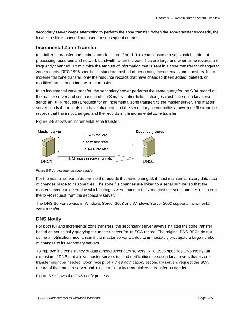
Chapter 8 – Domain Name System Overview
TCP/IP Fundamentals for Microsoft Windows Page: 235
secondary server keeps attempting to perform the zone transfer. When the zone transfer succeeds, the
local zone file is opened and used for subsequent queries.
Incremental Zone Transfer
In a full zone transfer, the entire zone file is transferred. This can consume a substantial portion of
processing resources and network bandwidth when the zone files are large and when zone records are
frequently changed. To minimize the amount of information that is sent in a zone transfer for changes to
zone records, RFC 1995 specifies a standard method of performing incremental zone transfers. In an
incremental zone transfer, only the resource records that have changed (been added, deleted, or
modified) are sent during the zone transfer.
In an incremental zone transfer, the secondary server performs the same query for the SOA record of
the master server and comparison of the Serial Number field. If changes exist, the secondary server
sends an IXFR request (a request for an incremental zone transfer) to the master server. The master
server sends the records that have changed, and the secondary server builds a new zone file from the
records that have not changed and the records in the incremental zone transfer.
Figure 8-8 shows an incremental zone transfer.
Figure 8-8 An incremental zone transfer
For the master server to determine the records that have changed, it must maintain a history database
of changes made to its zone files. The zone file changes are linked to a serial number so that the
master server can determine which changes were made to the zone past the serial number indicated in
the IXFR request from the secondary server.
The DNS Server service in Windows Server 2008 and Windows Server 2003 supports incremental
zone transfer.
DNS Notify
For both full and incremental zone transfers, the secondary server always initiates the zone transfer
based on periodically querying the master server for its SOA record. The original DNS RFCs do not
define a notification mechanism if the master server wanted to immediately propagate a large number
of changes to its secondary servers.
To improve the consistency of data among secondary servers, RFC 1996 specifies DNS Notify, an
extension of DNS that allows master servers to send notifications to secondary servers that a zone
transfer might be needed. Upon receipt of a DNS notification, secondary servers request the SOA
record of their master server and initiate a full or incremental zone transfer as needed.
Figure 8-9 shows the DNS notify process.

Chapter 8 – Domain Name System Overview
TCP/IP Fundamentals for Microsoft Windows Page: 236
Figure 8-9 The DNS notify process
To determine the secondary servers to which notifications should be sent, the master server maintains
a notify list (a list of IP addresses) for each zone. The master server sends notifications to only the
servers in the notify list when the zone is updated.
The DNS Server service in Windows Server 2008 and Windows Server 2003 supports the configuration
of a notify list (a list of IPv4 addresses) for each zone.

Chapter 8 – Domain Name System Overview
TCP/IP Fundamentals for Microsoft Windows Page: 237
DNS Dynamic Update
DNS was originally defined as a name resolution scheme for relatively static names and addresses;
DNS records contained information about servers, whose name and address configuration did not
change often. Therefore, the manual administration of resource records in zone files was manageable.
These original assumptions work well for an environment that is based on server and client computers
that are statically configured, in which the client computers communicate only with the server
computers and address configuration does not change. With the advent of peer-to-peer
communications and applications and the Dynamic Host Configuration Protocol (DHCP), both of the
assumptions of static DNS are challenged. In a Windows-based environment, client computers often
communicate directly with each other and are automatically configured using DHCP. To communicate
with each other, client computers must be able to resolve each other's names; therefore they must have
corresponding DNS resource records. With DHCP, the address configuration of client computers could
change every time they start. Manually administering DNS records for this environment is obviously
impractical.
Therefore, RFC 2136 defines DNS dynamic update to provide an automated method to populate the
DNS namespace with the current names and addresses for client and server computers by dynamically
updating zone data on a zone's primary server. With DNS dynamic update, DNS records are
automatically created, modified, and removed by either host computers or DHCP servers on their
behalf. For example, a client computer that supports DNS dynamic update sends UPDATE messages
to its DNS server to automatically add A, AAAA, and PTR records. The DNS server, which must also
support DNS dynamic update, verifies that the sender is permitted to make the updates and then
updates its local zone files.
The DNS Client service in Windows Vista, Windows XP, Windows Server 2008, and Windows Server
2003 and the DNS Server service in Windows Server 2008 and Windows Server 2003 support DNS
dynamic update.

Chapter 8 – Domain Name System Overview
TCP/IP Fundamentals for Microsoft Windows Page: 238
Chapter Summary
The chapter includes the following pieces of key information:
DNS is a namespace and a protocol for replicating databases and resolving FQDNs used on the
Internet and intranets. DNS consists of the domain namespace, name servers that store resource
records, and DNS resolvers.
A domain is a branch of the DNS namespace beginning at its root node. All of the resource records in a
domain are stored in zones on DNS servers. A zone is a contiguous portion of a DNS domain whose
information is stored in a file on a DNS server.
On the Internet, DNS consists of the root domain, top-level domains, and second-level domains. IANA
manages the names and DNS servers of the root domain and the top-level domains. Individual
organizations are responsible for managing the names in their second-level domains.
DNS resolvers use either recursive or iterative queries. A recursive query is used to request definitive
information about a name, and DNS clients typically use them for FQDN resolution. An iterative query is
used to request best-effort information about a name, and DNS servers typically use them to query
other DNS servers.
Forward lookups provide an IP address based on an FQDN. Reverse lookups provide an FQDN based
on an IP address.
DNS servers can have the role of a primary server (in which the records are modified by the DNS
administrator) or a secondary server (in which the records are obtained from another server) for each
zone for which they are authoritative. A master server is a server from which a secondary server
obtains a zone transfer.
DNS defines many types of resource records, the most common of which are SOA, A, AAAA, NS, PTR,
CNAME, MX, and SRV.
Zone transfers can transfer either the entire zone file (known as a full zone transfer) or just the records
that have changed (known as an incremental zone transfer). DNS Notify is a standard mechanism by
which a master name server notifies secondary name servers to check for changes in zone files.
DNS dynamic update is a standard method for hosts, or DHCP servers on behalf of hosts, to
automatically update the zones of primary DNS servers with resource records that correspond to
current names and address configurations.

Chapter 8 – Domain Name System Overview
TCP/IP Fundamentals for Microsoft Windows Page: 239
Chapter Glossary
DNS – See Domain Name System (DNS).
DNS dynamic update - An update to the DNS standard that permits DNS clients to dynamically register
and update their resource records in the zones of the primary server.
DNS server – A server that maintains a database of mappings of FQDNs to various types of data, such
as IP addresses.
domain – Any branch of the DNS namespace.
Domain Name System (DNS) – A hierarchical, distributed database that contains mappings of DNS
domain names to various types of data, such as IP addresses. DNS enables the location of computers
and services by user-friendly names and the discovery of other information stored in the database.
forward lookup – A DNS query that maps an FQDN to an IP address.
forwarder - A DNS server designated by other internal DNS servers to be used to forward queries for
resolving external or offsite DNS domain names, such as those used on the Internet.
FQDN – See fully qualified domain name.
fully qualified domain name (FQDN) - A DNS name that has been stated to indicate its absolute location
in the domain namespace tree. An FQDN has a trailing period (.) to qualify its position relative to the
root of the namespace. An example is host.example.microsoft.com.
host name – The DNS name of a host or interface on a network. For one computer to find another, the
name of the computer to locate must either appear in the Hosts file on the computer that is looking, or
the name must be known by a DNS server. For most Windows-based computers, the host name and
the computer name are the same.
Host name resolution – The process of resolving a host name to a destination IP address.
Hosts file – A local text file in the same format as the 4.3 BSD release of UNIX /etc/hosts file. This file
maps host names to IP addresses, and it is stored in the systemroot\System32\Drivers\Etc folder.
iterative query - A query made to a DNS server for the best answer the server can provide.
master server – A DNS server that is authoritative for a zone and that is also a source of zone
information for other secondary servers. A master server can be either a primary or secondary master
server, depending on how the server obtains its zone data.
primary server – A DNS server that is authoritative for a zone and that can be used as a point of update
for the zone. Only primary servers can be updated directly to process zone updates, which include
adding, removing, or modifying resource records that are stored as zone data.
recursive query – A query made to a DNS server in which the requester asks the server to assume the
full workload and responsibility for providing a complete answer to the query. The DNS server will then
use separate iterative queries to other DNS servers on behalf of the requester to assist in completing
an answer for the recursive query.
reverse lookup – A DNS query that maps an IP address to an FQDN.
root domain - The beginning of the DNS namespace.

Chapter 8 – Domain Name System Overview
TCP/IP Fundamentals for Microsoft Windows Page: 240
secondary server - A DNS server that is authoritative for a zone and that obtains its zone information
from a master server.
second-level domain – A DNS domain name that is rooted hierarchically at the second tier of the
domain namespace, directly beneath the top-level domain names. Top-level domain names include
.com and .org. When DNS is used on the Internet, second-level domains are names that are registered
and delegated to individual organizations and businesses.
subdomain - A DNS domain located directly beneath another domain (the parent domain) in the
namespace tree. For example, example.microsoft.com would be a subdomain of the domain
microsoft.com.
top-level domains – Domain names that are rooted hierarchically at the first tier of the domain
namespace directly beneath the root (.) of the DNS namespace. On the Internet, top-level domain
names such as .com and .org are used to classify and assign second-level domain names (such as
microsoft.com) to individual organizations and businesses according to their organizational purpose.
zone – A manageable unit of the DNS database that is administered by a DNS server. A zone stores
the domain names and data of the domain with a corresponding name, except for domain names stored
in delegated subdomains.
zone transfer - The synchronization of authoritative DNS data between DNS servers. A DNS server
configured with a secondary zone periodically queries its master server to synchronize its zone data.

Chapter 9 – Windows Support for DNS
TCP/IP Fundamentals for Microsoft Windows Page: 241
Chapter 9 – Windows Support for DNS
Abstract
This chapter describes the details of Domain Name System (DNS) support in Windows, which consists of the DNS
Client and DNS Server services. Windows Vista and Windows XP include the DNS Client service, and Windows Server
2008 and Windows Server 2003 include both the DNS Client and the DNS Server services. A network administrator
must understand the capabilities and configuration of both the DNS Client and DNS Server services to effectively
manage and troubleshoot a DNS name infrastructure and DNS name resolution behavior on a Windows network.

Chapter 9 – Windows Support for DNS
TCP/IP Fundamentals for Microsoft Windows Page: 242
Chapter Objectives
After completing this chapter, you will be able to:
Describe the capabilities and configuration of the DNS Client service.
Describe the name resolution process of the DNS Client service.
List and describe the features of the DNS Server service.
Install the DNS Server service, and configure its properties.
Configure DNS zones and zone transfers.
Delegate authority for zones.
Configure DNS dynamic update behavior for both the DNS Client service and the DNS Server service.
Configure Windows Internet Name Service (WINS) lookup and WINS reverse lookup.
Describe how to use the Nslookup tool.

Chapter 9 – Windows Support for DNS
TCP/IP Fundamentals for Microsoft Windows Page: 243
The DNS Client Service
The DNS Client service in Windows Vista, Windows XP, Windows Server 2008, and Windows
Server 2003 is responsible for name resolution, caching of name resolution attempts (including
negative caching), tracking connection-specific domain names, and prioritizing multiple resource
records of the same type based on their IP addresses.
The following sections describe how to configure the DNS Client service and how it resolves names.
DNS Client Configuration
You can configure the DNS Client service in the following ways:
Automatically, using Dynamic Host Configuration Protocol (DHCP) and DHCP options.
Manually, using either the Netsh tool or the properties of the Internet Protocol Version 4 (TCP/IPv4) or
Internet Protocol (TCP/IP) component in the Network Connections folder.
Automatically, for Point-to-Point Protocol (PPP) connections.
Automatically, using Computer Configuration Group Policy.
To determine the IP addresses of the DNS servers and the DNS domain name assigned to the
connections of your computer running Windows Vista, Windows XP, Windows Server 2008, or
Windows Server 2003, do one of the following:
Use the ipconfig /all command.
Use the netsh interface ipv4 show dns, netsh interface ipv6 show dns or netsh interface ip show
dns commands.
Open the Network Connections folder, right-click a connection, and click Status. Click the Support tab,
and then click Details.
The following sections describe how to configure the DNS Client service.
DHCP Configuration of the DNS Client Service
As described in Chapter 6, "Dynamic Host Configuration Protocol," DHCP provides IP configuration
information to DHCP clients. You can assign the IPv4 addresses of DNS servers to DHCP clients by
configuring the DNS Servers DHCP option (option 6). You can assign a DNS domain name to DHCP
clients by configuring the DNS Domain Name DHCP option (option 15). You can assign the IPv6
addresses of DNS servers to DHCPv6 clients by configuring the DNS Recursive Name Server IPv6
Address List option. If DNS servers or the connection-specific domain name are manually configured in
the properties of the Internet Protocol Version 4 (TCP/IPv4) or Internet Protocol (TCP/IP) component,
the DNS Client service ignores the DHCP-based DNS settings.
Manual Configuration of the DNS Client Service Using Network Connections
To manually configure the DNS Client service on a specific connection using the Network Connections
folder, obtain the properties of the Internet Protocol Version 4 (TCP/IPv4) or Internet Protocol (TCP/IP)
component for the network connection. You can configure the following DNS Client service settings

Chapter 9 – Windows Support for DNS
TCP/IP Fundamentals for Microsoft Windows Page: 244
from the properties of the Internet Protocol Version 4 (TCP/IPv4) or Internet Protocol (TCP/IP)
component:
Primary and alternate DNS server addresses for the connection.
Primary and alternate DNS server addresses for the alternate configuration for the connection.
Advanced DNS properties.
Figure 9-1 shows the configuration of primary and alternate DNS server addresses on the General tab.
Figure 9-1 Primary and alternate DNS servers on the General tab
In this example, IPv4 addresses for primary and alternate DNS servers are configured for a connection
with a static IPv4 address configuration. You can also configure addresses for primary and alternate
DNS servers even when the connection is configured to obtain an IPv4 address automatically (using
DHCP).
As Figure 9-2 shows, you can also specify the IPv4 addresses of a primary and an alternate DNS
server when you configure an alternate configuration (for example, so that you can seamlessly operate
your laptop computer on a work network that uses DHCP and on a home network that uses static IPv4
configuration).

Chapter 9 – Windows Support for DNS
TCP/IP Fundamentals for Microsoft Windows Page: 245
Figure 9-2 Primary and alternate DNS servers on the Alternate Configuration tab
The example in Figure 9-2 shows the configuration of a primary DNS server corresponding to an
Internet gateway device (IGD) on a home network. The IGD is acting as a DNS server for all of the
computers on the home network.
To manually configure the IPv4 addresses of more than two DNS servers or to configure additional
DNS Client service settings for a connection, open the Network Connections folder, right-click the
connection, and click Properties. Then click Internet Protocol Version 4 (TCP/IPv4) or Internet
Protocol (TCP/IP) without clearing its check box, click Properties, click Advanced, and click the DNS
tab. Figure 9-3 shows an example of the DNS tab.
Figure 9-3 The DNS tab from the advanced configuration of Internet Protocol Version 4 (TCP/IPv4)
From the DNS tab, you can configure the following:

Chapter 9 – Windows Support for DNS
TCP/IP Fundamentals for Microsoft Windows Page: 246
DNS server addresses, in order of use Lists one or more DNS servers that the computer queries, in
order. If you want to manually configure more than two DNS servers, you must add them to this list and
configure their order.
Append primary and connection-specific DNS suffixes Specifies whether you want to use the
primary and connection-specific DNS suffixes to attempt to resolve unqualified names. An unqualified
name has no trailing period, such as "dev.example". In contrast, a fully qualified name has a trailing
period, such as "dev.example.com." The primary DNS suffix is assigned to the computer and configured
from the Computer Name tab of the System item in Control Panel. Connection-specific DNS suffixes
are assigned to each connection, either manually or through the DNS Domain Name DHCP option. For
more information about the name resolution process, see the “Name Resolution Behavior” section of
this chapter.
Append parent suffixes of the primary DNS suffix Specifies that during name resolution, the DNS
Client service uses the parent suffixes of the primary DNS suffix, up to the second-level domain, in an
attempt to resolve unqualified host names.
Append these DNS suffixes Specifies a list of DNS suffixes to try during name resolution, instead of
the primary and connection-specific DNS suffixes.
DNS suffix for this connection Specifies a DNS suffix for this specific connection. The DNS Client
service uses the connection-specific suffix to identify this connection on the computer, whereas the
DNS Client service uses the primary suffix to identify the computer regardless of the connection. If you
specify a DNS suffix, the DNS Client service ignores the DNS suffix obtained through the DNS Domain
Name DHCP option.
Register this connection’s addresses in DNS Specifies that the DNS Client service uses DNS
dynamic update to register the IP addresses of this connection with the primary name of the computer,
which consists of the computer name combined with the primary suffix.
Use this connection’s DNS suffix in DNS registration Specifies that the DNS Client service uses
DNS dynamic update to register the IP addresses of this connection with the name of the connection—
the computer name combined with the connection-specific suffix—in addition to the primary name of the
computer.
To manually configure the DNS Client service in Windows Vista or Windows Server 2008 for the IPv6
addresses of DNS servers on a specific connection, obtain the properties of the Internet Protocol
Version 6 (TCP/IPv6) component for the network connection. You can configure the following DNS
Client service settings from the properties of the Internet Protocol Version 6 (TCP/IPv6) component:
Primary and alternate DNS server IPv6 addresses for the connection.
Advanced DNS client properties.
For the Internet Protocol Version 6 (TCP/IPv6) component, configuration of the IPv6 addresses of DNS
servers and advanced DNS client properties is very similar to IPv4.
Manual Configuration Using Netsh
You can also configure DNS server settings for the DNS Client service from the command line using
the netsh interface ipv4 set dnsserver or netsh interface ip set dns commands.

Chapter 9 – Windows Support for DNS
TCP/IP Fundamentals for Microsoft Windows Page: 247
By default, the DNS Client service uses IPv4 for all DNS messages. For computers running Windows
Vista or Windows Server 2008, use the following command:
netsh interface ipv6 set dnsserver [name=]String [source=]dhcp|static [addr=]IPv6Address|none
[[register=]none|primary|both]
Windows XP and Windows Server 2003 do not support DNS traffic over IPv6.
Configuration for Remote Access Clients
Dial-up or virtual private network-based remote access clients running Windows Vista, Windows Server
2008, Windows XP, or Windows Server 2003 obtain the initial configuration of a primary and alternate
DNS server during the negotiation of the Point-to-Point (PPP) connection. The PPP negotiation
includes the Primary DNS Server Address and Secondary DNS Server Address options in the Internet
Protocol Control Protocol (IPCP) as specified in RFC 1877.
Remote access clients running Windows Vista, Windows XP, Windows Server 2008, or Windows
Server 2003 also use a DHCPInform message to obtain an updated list of DNS servers and the DNS
domain name. If the remote access server running Windows Server 2008 or Windows Server 2003 is
correctly configured with the DHCP Relay Agent routing protocol component, it forwards the
DHCPInform message to a DHCP server and forwards the response (a DHCPAck message) back to
the remote access client.
If the remote access client receives a response to the DHCPInform message, the DNS servers
contained in the DHCPAck message replace the DNS servers configured during the PPP connection
negotiation.
Configuration of DNS Settings Using Group Policy
You can also configure DNS settings using Computer Configuration Group Policy and the Group Policy
Object Editor snap-in. By using this snap-in, you can modify Group Policy objects for system containers
(such as sites, domains, or organizational units) within Active Directory. To configure DNS settings,
open the Group Policy Object Editor snap-in, and click the Computer Configuration\Administrative
Templates\Network\DNS Client node in the tree, as Figure 9-4 shows.

Chapter 9 – Windows Support for DNS
TCP/IP Fundamentals for Microsoft Windows Page: 248
Figure 9-4 DNS settings in Computer Configuration Group Policy
Group Policy-based DNS settings override the equivalent settings configured on the local computer or
through DHCP.
Name Resolution Behavior
When an application uses the getaddrinfo() or gethostbyname() Windows Sockets functions, the
resolver component of the DNS Client service performs name resolution as described in Chapter 7,
“Host Name Resolution.” The DNS Client service checks the local host name and the local DNS client
resolver cache, and then the service sends out DNS Name Query Request messages.
If DNS name resolution fails and the name is longer than 15 bytes, name resolution fails and TCP/IP for
Windows indicates the error condition to the application. If the name is 15 bytes or shorter in length, the
resolver verifies whether NetBIOS over TCP/IP is enabled. If it is not enabled, name resolution fails. If
NetBIOS is enabled, the resolver converts the name to a NetBIOS name and attempts NetBIOS name
resolution.
Before the resolver sends any DNS Name Query Request messages, it determines the type of name to
resolve. An application can submit one of the following types of names:
Fully qualified domain name (FQDN)
Names that are terminated with a period, indicating the name relative to the root domain of the
DNS. For example, host7.example.com. is an FQDN.
Single-label, unqualified domain names
Names that consist of a single label and contain no periods. For example host7 is a single-label,
unqualified domain name.
Multiple-label, unqualified domain names
Names that contain more than one label and one or more periods but are not terminated with a
period. For example, host7.example or example.com are multiple-label, unqualified domain names.
Name Resolution for FQDNs
When the application specifies an FQDN, the resolver queries DNS using that name. No other
combinations are tried.
Name Resolution for Single-Label, Unqualified Domain Names
When the application specifies a single-label, unqualified domain name, the resolver systematically
appends different DNS suffixes to the single-label, unqualified domain name; adds periods to make
them FQDNs; and submits them to DNS for name resolution. The resolver appends the DNS suffixes to
the single-label, unqualified domain name based on the state of the Append primary and connection
specific DNS suffixes or Append these suffixes check boxes on the DNS tab in the Advanced
TCP/IP Settings dialog box of the Internet Protocol Version 4 (TCP/IPv4) or Internet Protocol (TCP/IP)
component.
If the Append primary and connection specific DNS suffixes check box is selected, the resolver
appends the following names and sends separate queries:

Chapter 9 – Windows Support for DNS
TCP/IP Fundamentals for Microsoft Windows Page: 249
The primary DNS suffix, as specified on the Computer Name tab of the System item of Control Panel.
Each connection-specific DNS suffix, assigned either through DHCP or specified in the DNS suffix for
this connection box on the DNS tab in the Advanced TCP/IP Settings dialog box for each
connection.
If resolution is still not successful and the Append parent suffixes of the primary DNS suffix check
box is selected, the resolver creates new FQDNs by appending the single-label, unqualified domain
name with the parent suffix of the primary DNS suffix name, and the parent of that suffix, and so on,
stopping at the second-level domain name. This process is known as name devolution. For example, if
the application specified the name emailsrv7 and the primary DNS suffix is central.example.com., the
resolver tries to resolve the FQDNs of emailsrv7.central.example.com. and emailsrv7.example.com.
If resolution is still not successful and the Append these suffixes check box is selected, the resolver
appends each suffix from the search list in order and submits the FQDN to the DNS server until the
resolver finds a match or reaches the end of the list. For example, if the application specified the name
filesrv11 and the DNS suffix list consists of admin.wcoast.example.com., admin.ecoast.example.com.,
and admin.central.example.com., the resolver tries the FQDNs of
filesrv11.admin.wcoast.example.com., filesrv11.admin.ecoast.example.com., and
filesrv11.admin.central.example.com.
Name Resolution for Multiple-Label, Unqualified Domain Names
When an application specifies a multiple-label, unqualified domain name, the DNS resolver uses the
same process as that for a single-label, unqualified domain name to resolve the name.

Chapter 9 – Windows Support for DNS
TCP/IP Fundamentals for Microsoft Windows Page: 250
The DNS Server Service
The DNS Server service in Windows Server 2008 and Windows Server 2003 supports the following
features:
An Internet standards-compliant DNS server
DNS is an open protocol and is standardized by a set of Internet Engineering Task Force (IETF)
RFCs. The DNS Server service in Windows Server 2003 supports and complies with these
standard specifications.
Interoperability with other DNS server implementations
Because the DNS Server service is RFC-compliant and uses standard DNS data file and resource
record formats, it can successfully work with most other DNS server implementations, such as
those that use the Berkeley Internet Name Domain (BIND) software.
Support for Active Directory
DNS is required to support Active Directory. If you make a server an Active Directory domain
controller, you can automatically install and configure the DNS Server service on that server.
Enhancements to DNS zone storage in Active Directory
DNS zones can be stored in the domain or application directory partitions of Active Directory. A
partition is a data structure stored in Active Directory that is used for different replication purposes.
You can specify in which Active Directory partition to store the zone and, consequently, the set of
domain controllers among which the zone's data is replicated.
Conditional forwarding
The DNS Server service extends standard forwarder support with additional capability as a
conditional forwarder. A conditional forwarder is a DNS server that forwards DNS queries according
to the DNS domain name in the query. For example, you can configure a DNS server to forward all
the queries it receives for names ending with wcoast.example.com to one or multiple DNS servers.
Stub zones
DNS supports a new zone type called a stub zone, which is a copy of a zone that contains only the
resource records required to identify the authoritative DNS servers for that zone. A DNS server that
hosts a parent zone and a stub zone for one of the parent zone's delegated child zones can receive
updates from the authoritative DNS servers for the child zone.
Integration with other Microsoft networking services
The DNS Server service offers integration with other services and contains features beyond those
specified in the DNS RFCs. These include integration with Active Directory, WINS, and DHCP.
Improved ease of administration
The DNS snap-in offers a graphical user interface for managing the DNS Server service. Also, you
can use several configuration wizards to perform common tasks for administering servers.

Chapter 9 – Windows Support for DNS
TCP/IP Fundamentals for Microsoft Windows Page: 251
You can also use the Dnscmd command-line tool to perform most of the tasks that you can perform
from the DNS snap-in. You can also use Dnscmd to write scripts and administer remote DNS
servers.
RFC-compliant support for the DNS dynamic update protocol
The DNS Server service allows clients to dynamically update address and pointer resource records,
based on the DNS dynamic update protocol that RFC 2136 defines. DNS dynamic update
eliminates the administration associated with manually managing DNS address and pointer
records. Computers running Windows can dynamically register their DNS names and IP addresses.
Support for secure dynamic updates in zones that are integrated with Active Directory
You can configure zones that are integrated with Active Directory for secure dynamic update. With
secure dynamic update, only authorized computers can make changes to a resource record.
Support for incremental zone transfer between servers
DNS servers use zone transfers to replicate information about a portion of the DNS namespace.
The DNS Server service uses incremental zone transfers to replicate only the changed portions of a
zone, conserving network bandwidth.
Support for new resource record types
The DNS Server service includes support for several new resource record (RR) types, such as
service location (SRV) and Asynchronous Transfer Mode address (ATMA) resource records. These
types expand the use of DNS as a name database service.
Support for aging and scavenging of records
The DNS service is capable of aging and scavenging records. When enabled, this feature can
remove stale records from DNS.
The DNS Server service in Windows Server 2008 supports the following additional features:
Background zone loading
Enhancements to support IPv6
Support for read-only domain controllers (RODCs)
The ability to host global single-label names
For more information, see DNS Enhancements in Windows Server 2008.
Installing the DNS Server Service
You can install the DNS Server service in Windows Server 2003 in the following ways:
As a Windows component using the Add or Remove Programs item of Control Panel (Windows Server
2003).
Using the Active Directory Installation Wizard (Dcpromo.exe).
Using the Manage Your Server Wizard (Windows Server 2003).
Using the Server Manager snap-in (Windows Server 2008)
To install the DNS Server service with Server Manager in Windows Server 2008, do the following:

Chapter 9 – Windows Support for DNS
TCP/IP Fundamentals for Microsoft Windows Page: 252
1. Click Start, point to Programs, point to Administrative Tools, and then click Server Manager.
2. In the console tree, right-click Roles, click Add Roles, and then click Next.
3. On the Select Server Roles page, select the DNS Server check box, and then click Next.
4. Follow the pages of the Add Roles wizard to perform an initial configuration of the DNS Server
service.
To install the DNS Server service with Add or Remove Programs in Windows Server 2003, do the
following:
1. Click Start, click Control Panel, double-click Add or Remove Programs, and then click
Add/Remove Windows Components.
2. In Components, select the Networking Services check box, and then click Details.
3. In Subcomponents of Networking Services, select the Domain Name System (DNS) check box,
click OK, and then click Next.
4. If prompted, in Copy files from, type the full path to the distribution files for Windows Server 2003,
and then click OK.
To install the DNS Server service, you must be logged on as a member of the Administrators group on
the local computer, or you must have been delegated the appropriate authority. If the computer is joined
to a domain, members of the Domain Admins group might be able to perform this procedure.
After you install the DNS Server service, you can decide how to configure it and its zones. Local text
files contain information about zones and the boot process for the DNS Server service, and you can
use a text editor to update that information. However, this method is not described in this chapter. The
DNS snap-in and the Dnscmd command-line tool simplify maintenance of the DNS Server service, and
you should use them whenever possible. After you begin to use snap-in-based or command-line
management of the DNS Server service, manually editing the text files is not recommended.
DNS and Active Directory
DNS and Active Directory are integrated to provide a location service for Active Directory operations
and to store DNS zones in Active Directory, taking advantage of Active Directory security and
replication.
A directory is a hierarchical structure that stores information about objects on the network. A directory
service, such as Active Directory, provides the methods for storing directory data and making this data
available to network users and administrators. For example, Active Directory stores information about
user accounts such as names, locations, phone numbers, and so on, and Active Directory enables
authorized users on the same network to access this information.
Active Directory Location Service
Active Directory requires the use of DNS to store various types of DNS resource records so that Active
Directory clients and domain controllers can locate one another and perform various types of domain
operations.
For example, an Active Directory client that starts up uses DNS queries to locate the nearest Active
Directory domain controller in its site to perform logon and authentication functions. To facilitate this
Chapter 9 – Windows Support for DNS
TCP/IP Fundamentals for Microsoft Windows Page: 253
location service for Active Directory clients, the following records must exist in the DNS servers that the
Active Directory clients use:
the _ldap._tcp.dc._msdcs.DNSDomainName service (SRV) resource record
the address (A) resource records for the DNS names of the domain controllers specified in the data
field of the _ldap._tcp.dc._msdcs.DNSDomainName SRV resource records
These records are automatically added when you install a DNS server using the Active Directory
Installation Wizard.
Storage of Zones Integrated with Active Directory
After you have installed Active Directory, you have two options for storing and replicating your zones
when the DNS Server service is running on a domain controller:
Standard zone storage, using a text-based file.
Zones are located in .Dns files that are stored in the systemroot\System32\Dns folder. Zone file
names correspond to the zone root name. For example, the wcoast.example.com. domain uses the
wcoast.example.com.dns file.
Directory-integrated zone storage, using the Active Directory database.
Zones are located in the Active Directory tree under the domain or application directory partition.
Each directory-integrated zone is stored in a dnsZone container object that corresponds to the zone
root name.
For networks deploying DNS to support Active Directory, directory-integrated primary zones are
strongly recommended and provide the following benefits:
Zones have multimaster update and enhanced security based on the capabilities of Active Directory.
In a standard zone storage model, DNS updates are conducted based on a single-master update
model. In this model, a single authoritative DNS server for a zone is designated as the primary
server for the zone, and that server maintains the master copy of the zone in a local file. With this
model, the primary server for the zone represents a single fixed point of failure. If this server is not
available, update requests from DNS clients are not processed for the zone.
With directory-integrated storage, updates to DNS are conducted based on a multimaster update
model. In this model, any authoritative DNS server, such as a domain controller running a DNS
server, is designated as a primary source for the zone. Because the master copy of the zone is
maintained in the Active Directory database, which is fully replicated to all domain controllers, the
DNS servers operating on any domain controller for the domain can update the zone.
Zones are replicated and synchronized to new domain controllers automatically whenever a zone is
added to an Active Directory domain.
Although you can selectively remove the DNS Server service from a domain controller, directory-
integrated zones are already stored at each domain controller, so zone storage and management is
not an additional resource. Also, the methods used to synchronize directory-stored information offer
performance improvement over standard zone update methods, which can potentially require
transfer of the entire zone.

Chapter 9 – Windows Support for DNS
TCP/IP Fundamentals for Microsoft Windows Page: 254
By integrating storage of your DNS zone databases in Active Directory, you can streamline database
replication planning for your network.
When your DNS namespace and Active Directory domains are stored and replicated separately,
you need to plan and potentially administer each separately. For example, when using standard
DNS zone storage and Active Directory together, you would need to design, implement, test, and
maintain two different database replication topologies. You need one replication topology for
replicating directory data between domain controllers, and you need another topology for replicating
zone databases between DNS servers. With integrated DNS zone storage in Active Directory, you
must design and maintain only an Active Directory replication.
Directory replication is faster and more efficient than standard DNS replication.
Because Active Directory replication processing is performed on a per-property basis, only relevant
changes are propagated. Therefore, directory-stored zones require less traffic to synchronize
changes across the replication topology.
Only primary zones can be stored in the directory. A DNS server cannot store secondary zones in
Active Directory. It must store them in standard text files. The multimaster replication model of
Active Directory removes the need for secondary zones when all the zones are stored in Active
Directory. When all of the DNS servers in your organization are also domain controllers, all of your
DNS servers are primary servers for all of your zones.

Chapter 9 – Windows Support for DNS
TCP/IP Fundamentals for Microsoft Windows Page: 255
DNS Server Service Configuration
The configuration of the DNS Server service consists of a set of properties for the DNS server and
forward and reverse lookup zone files.
Properties of the DNS Server
To modify the properties of a DNS server, open the DNS snap-in, right-click the name of the server in
the tree, and then click Properties. Figure 9-5 shows an example of the resulting ServerName
Properties dialog box.
Figure 9-5 The properties dialog box for a DNS server
From this dialog box, you can configure properties on the following tabs:
Interfaces You can specify the IPv4 or IPv6 addresses on which the DNS Server service is listening
for incoming DNS messages. You can specify all the IPv4 or IPv6 addresses assigned to the DNS
server, or you can specify individual addresses (and, therefore interfaces) on which you want to receive
DNS traffic as a DNS server.
Forwarders You can specify the forwarding behavior of this DNS server including the ability to forward
based on a specific domain name (conditional forwarding), the list of IP addresses to which the server
should forward DNS traffic, timeout behavior, and whether to use recursive queries for each domain.
Advanced You can enable various options (such as round robin and subnet prioritization), the data
format for checking names, the location of zone data (Active Directory or local files), and scavenging
settings.
Root Hints You can configure the set of root domain servers that this DNS server uses during iterative
queries. Changes that you make on the Root Hints tab are updated in the Cache.dns file, which is
stored in the systemroot\System32\Dns folder. Using the Root Hints tab is the recommended method
of maintaining the list of root domain servers, rather than using a text editor to modify the Cache.dns
file.
Chapter 9 – Windows Support for DNS
TCP/IP Fundamentals for Microsoft Windows Page: 256
Debug Logging You can enable and configure various options for the DNS debug log file, which you
can use when troubleshooting DNS issues. The DNS debug log file is stored in
systemroot\System32\Dns\Dns.log. By default, debug logging is disabled.
Event Logging You can specify the level of logging for information stored in the DNS event log, which
you can view with the Event Viewer snap-in. By default, logging is enabled for all events.
Monitoring You can perform simple diagnostic functions to ensure the correct configuration and
operation of the DNS server, such as performing recursive and iterative queries and electing to run
them as needed or at a specified interval.
Security You can specify access control lists (ACLs) for DNS server administration. For more
information about ACLs, see Help and Support for Windows Server 2008 or Windows Server 2003.
Maintaining Zones
You can use the DNS snap-in to administer two main types of zones:
Forward lookup zones
Reverse lookup zones
Forward Lookup Zones
To create a forward lookup zone by using the DNS snap-in, open the snap-in, right-click the Forward
Lookup Zones node in the tree, and click New Zone. The New Zone Wizard launches and guides you
through creating a forward lookup zone. In the New Zone Wizard, you must specify the following:
Whether to create a primary, secondary, or stub zone
Whether to store the zone in Active Directory
For Active Directory storage, whether to replicate the zone to all DNS servers in the forest, to all DNS
servers in the domain, or to all domain controllers in the domain
What the FQDN of the zone should be
Whether to allow dynamic updates, to require secure dynamic updates, or both
For secondary and stub zones, from which master name servers (as specified by IPv4 or IPv6 address)
the DNS Server service obtains the zone data
To modify the properties of a forward lookup zone, open the DNS snap-in, right-click the zone under the
Forward Lookup Zones folder in the tree, and click Properties. Figure 9-6 shows an example of the
resulting ForwardZoneName Properties dialog box.

Chapter 9 – Windows Support for DNS
TCP/IP Fundamentals for Microsoft Windows Page: 257
Figure 9-6 The properties dialog box for a forward lookup zone
From this dialog box, you can configure properties on the following tabs:
General You can specify the zone's state (running or paused), the type of zone (primary, secondary, or
stub), its replication scope, and behaviors for dynamic update and aging/scavenging.
Start of Authority (SOA) You can view or specify all of the parameters of the SOA resource record for
the zone.
Name Servers You can view and change all of the Name Server (NS) resource records for the zone.
WINS You can specify the WINS lookup behavior. For more information, see "DNS and WINS
Integration" in this chapter.
Zone Transfers You can specify the zone transfer behavior for the zone (whether to allow zone
transfers, to which servers, and the notify list).
Security You can specify ACLs for zone administration.
Reverse Lookup Zones
To create a reverse lookup zone in the DNS snap-in, open the snap-in, right-click the Reverse Lookup
Zones node in the tree, and click New Zone. The New Zone Wizard launches and guides you through
creating a reverse lookup zone. In the New Zone Wizard, you must specify the following:
Whether to create a primary, secondary, or stub zone
Whether to store the zone in Active Directory
For Active Directory storage, whether to replicate the zone to all DNS servers in the forest, to all DNS
servers in the domain, or to all domain controllers in the domain
Either the IPv4 address prefix (up to the third octet), the IPv6 address prefix, or the reverse lookup zone
name
Whether to allow dynamic updates, and whether to require secure dynamic updates

Chapter 9 – Windows Support for DNS
TCP/IP Fundamentals for Microsoft Windows Page: 258
For secondary and stub zones, from which master name servers (as specified by IPv4 or IPv6 address)
the DNS Server service obtains the zone data
To modify the properties of a reverse lookup zone, open the DNS snap-in, right-click the zone under the
Reverse Lookup Zones folder in the tree, and click Properties. Figure 9-6 shows an example of the
resulting ReverseZoneName Properties dialog box.
Figure 9-7 The properties dialog box for a reverse lookup zone
From this dialog box, you can configure properties on the following tabs:
General You can specify the zone's state (running or paused), the type of zone (primary, secondary, or
stub), its replication scope, and behaviors for dynamic update and aging/scavenging.
Start of Authority (SOA) You can view or specify all of the parameters of the SOA resource record for
the zone.
Name Servers You can view and change all of the Name Server (NS) resource records for the zone.
WINS-R You can specify the WINS reverse lookup behavior. For more information, see "DNS and
WINS Integration" in this chapter.
Zone Transfers You can specify the zone transfer behavior for the zone (whether to allow zone
transfers, to which servers, and the notify list).
Security You can specify ACLs for zone administration.
Delegation
To perform a delegation, open the DNS snap-in, right-click the parent zone in the tree, and then click
New Delegation. The New Delegation Wizard launches and guides you through creating delegation
and glue records for a subdomain of an existing domain. In the New Delegation Wizard, you must
specify:
The name of the domain to delegate.
The FQDN and IPv4 or IPv6 addresses of the DNS servers to which the domain is being delegated.

Chapter 9 – Windows Support for DNS
TCP/IP Fundamentals for Microsoft Windows Page: 259
To complete the delegation, you create the delegated domain zones on the servers specified in the
New Delegation Wizard.
Zone Transfers
You can configure zone transfers from the Zone Transfers tab in the properties dialog box for the
zone. Figure 9-8 shows an example of the Zone Transfers tab for a forward lookup zone.
Figure 9-8 The Zone Transfers tab for a forward lookup zone
From the Zone Transfers tab, you can configure the following:
Whether zone transfers for the zone are allowed.
The servers to which zone transfers are allowed. You can specify any server, only the servers listed on
the Name Servers tab, or specific servers listed by IPv4 or IPv6 address.
The notify list (click Notify), from which you can specify the servers on the Name Servers tab or
specific servers listed by IPv4 address.
Resource Records
The DNS Server service stores resource records in their respective containers in a zone. You might
manually configure the following typical resource records:
IPv4 address records
IPv6 address records
Pointer records
IPv4 Address Records
To manually add an IPv4 address record (also known as an Address [A] record), open the DNS snap-
in, right-click the appropriate forward lookup zone in the tree, and then click New Host (A or AAAA) or
New Host (A). In the New Host dialog box, type the host portion of the domain name and its IPv4

Chapter 9 – Windows Support for DNS
TCP/IP Fundamentals for Microsoft Windows Page: 260
address. You can also automatically create the associated PTR record, allow an unauthenticated
update to the record, and specify the Time-to-Live (TTL) for the A and PTR records.
Computers running Windows automatically add their IPv4 host address resource records using dynamic
update. For more information, see "Dynamic Update and Secure Dynamic Update" in this chapter.
IPv6 Address Records
To manually add an IPv6 address record (also known as a AAAA record) in Windows Server 2008,
open the DNS snap-in, right-click the appropriate forward lookup zone in the tree, and then click New
Host (A or AAAA). For Windows Server 2003, click Other New Records. In the Resource Record
Type dialog box, click IPv6 Host (AAAA), and then click Create Record. In the New Host dialog box,
type the host portion of the domain name and its IPv6 address. You can also automatically delete the
record if it becomes stale and specify its TTL.
A computer running Windows with the IPv6 protocol automatically adds AAAA resource records for site-
local and global IPv6 addresses using dynamic update. For more information, see "Dynamic Update
and Secure Dynamic Update" in this chapter. The IPv6 protocol does not register link-local addresses
or global addresses with temporary interface identifiers using dynamic update.
Pointer Records
To manually add a Pointer (PTR) resource record for an IP address, open the DNS snap-in, right-click
the appropriate reverse lookup zone in the tree, and then click New Pointer (PTR). In the New
Resource Record dialog box, type the host IP address (in reverse order, if needed) and the host's
FQDN. You can also automatically delete the record if it becomes stale, allow an unauthenticated
update to the record, and specify its TTL.
Computers running Windows automatically add their PTR records using dynamic update. For more
information, see "Dynamic Update and Secure Dynamic Update" in this chapter.
DNS Traffic Over IPv6
By default, the DNS Server service in Windows Server 2008 listens for DNS traffic sent over IPv6. By
default, the DNS Server service in Windows Server 2003 does not listen for DNS traffic sent over IPv6.
You can configure DNS servers running Windows Server 2003 and DNS clients running Windows Vista
or Windows Server 2008 to use DNS traffic over IPv6 through either locally configured or well-known
unicast addresses of DNS servers.
Using Locally Configured Unicast Addresses
In this method, DNS clients and servers send DNS traffic over IPv6 to a unicast address locally
assigned to the DNS server, such as a site-local or global address of the DNS server configured
through IPv6 address autoconfiguration. This method requires the following steps:
1. On each DNS server running Windows Server 2003, enable the DNS Server service for DNS traffic
by using the dnscmd /config /EnableIPv6 1 command and then restarting the DNS Server service.
2. Obtain the global or unique local addresses of each DNS server by using the ipconfig command.
3. Configure each Windows Vista or Windows Server 2008 DNS client computer with the unicast IPv6
addresses of your DNS servers using the netsh interface ipv6 add dnsserver
Chapter 9 – Windows Support for DNS
TCP/IP Fundamentals for Microsoft Windows Page: 261
interface=NameOrIndex address=IPv6Address index=PreferenceLevel command.
Using Well-Known Unicast Addresses
In this method, DNS clients and servers send DNS traffic over IPv6 to a set of well-known unicast
addresses that have been manually configured on the DNS server. Computers running Windows Vista
or Windows Server 2008 automatically attempt to use DNS servers at the well-known unicast
addresses of FEC0:0:0:FFFF::1, FEC0:0:0:FFFF::2, and FEC0:0:0:FFFF::3. This method requires the
following steps:
1. Determine which well-known unicast addresses to assign to which DNS servers.
2. On each DNS server, add one or more of the well-known unicast addresses using the netsh
interface ipv6 add address interface=NameOrIndex address=IPv6Address command.
3. Add host routes for the well-known unicast addresses to your routing infrastructure so that the DNS
servers are reachable from all of your IPv6-based DNS client computers. First, you must add host
routes for the DNS server addresses to the neighboring routers of the DNS servers. If you are using
an IPv6 routing protocol, configure it to propagate host routes to the non-neighboring IPv6 routers. If
you are using static IPv6 routers, add host routes with the appropriate next-hop and metric
information to all the non-neighboring routers.
Dynamic Update and Secure Dynamic Update
DHCP servers assign IPv4 addresses and other configuration settings to DHCP client computers.
These addresses are valid for a specific lease time. If the DHCP client computer cannot renew the
current lease or moves to another subnet, the DHCP server assigns a new IPv4 address configuration
to the client computer. This variability of IPv4 address configuration for DHCP client computers
complicates DNS administration because you must update A and PTR resource records.
RFC 2136 describes the DNS dynamic update protocol, which keeps DNS current in a DHCP
environment. DNS dynamic update allows DNS client computers to both register and dynamically
update their resource records with a DNS server whenever the client computers’ IP addresses or
names change. This process reduces the need for you to administer zone records manually, especially
for computers that use DHCP.
Windows supports DNS dynamic update for both the DNS clients and servers. For DNS servers, you
can use the DNS Server service to enable dynamic updates on a per-zone basis for either standard
primary zones or zones that are integrated with Active Directory.
DNS clients running Windows register A and PTR resource records for IPv4 addresses and AAAA
records for IPv6 addresses in DNS by default. Additionally, domain controllers and other service-
providing computers register service (SRV) resource records in DNS. Because SRV resource records
provide a way to resolve service names to IP addresses, registering them with DNS allows client
computers running Windows to locate domain controllers and other types of servers.
DNS clients that are running Windows send dynamic updates in the following circumstances:
For statically assigned IP addresses, when the computer is started or an IP address on any of the
computer’s network connections is added, removed, or modified.

Chapter 9 – Windows Support for DNS
TCP/IP Fundamentals for Microsoft Windows Page: 262
For dynamically assigned IP addresses, when an IP address lease on any of the computers’ network
connections changes or is renewed with the DHCP server (for example, when the computer is started
or the ipconfig /renew command is used).
When the Net Logon service is started on domain controllers.
When a member server is promoted to a domain controller.
When the user runs the ipconfig /registerdns command to manually force a refresh of name
registration in DNS.
Periodically after the initial dynamic update (by default, every seven days).
When one of these events triggers a dynamic update, the DHCP Client service on the computer running
Windows sends the update. For IPv4-based addresses, the DHCP Client service sends the updates,
rather than the DNS Client service, because the DHCP Client service provides IP address
configuration, whether static or dynamic, to TCP/IP in Windows and monitors changes in IP address
configuration.
For IPv6-based addresses, the IPv6 protocol component sends the updates when the computer is
started or an IPv6 address on any of the computer’s network connections is added, removed, or
modified.
How Computers Running Windows Update their DNS Names
The specific mechanism and types of records registered by a computer running Windows depends on
whether its IPv4 configuration is static (configured manually) or automatic (configured using DHCP):
By default, computers running Windows that are manually configured with static IPv4 addresses
attempt to dynamically register A and PTR resource records for all configured DNS names.
By default, computers running Windows that are automatically configured with IPv4 addresses allocated
by a DHCP server attempt to dynamically register A resource records. The DHCP server attempts to
dynamically register the PTR resource records on the DHCP client's behalf. This behavior is controlled
by:
The inclusion of the Client FQDN DHCP option (option 81) in the DHCPRequest message sent by
the DHCP client.
In the DHCP snap-in, the settings on the DNS tab (see Figure 9-9) for the properties of a DHCP
server or the properties of a DHCP scope.
For DHCP clients that do not send the Client FQDN option, the DHCP server does not automatically
register the A or PTR resource records on the DHCP client's behalf. To enable this support, you can
select the Dynamically update DNS A and PTR records for DHCP clients that do not request
updates check box on the DNS tab.
Figure 9-9 shows the DNS tab in the properties dialog box of a DHCP server.

Chapter 9 – Windows Support for DNS
TCP/IP Fundamentals for Microsoft Windows Page: 263
Figure 9-9 The DNS tab on the properties of a DHCP server
DNS Dynamic Update Process
A DNS client computer running Windows uses the following process to perform a DNS dynamic update:
1. The client queries its configured DNS server to find the Start of Authority (SOA) resource record for
the DNS zone of the DNS name that is being updated.
2. The DNS client's configured DNS server performs the standard name resolution process and sends
the SOA record, which contains the IP address of the primary name server for the queried DNS zone.
3. The client sends a dynamic update request to the primary name server for the zone of the DNS name
that is being updated.
This request might include a list of prerequisites that must be fulfilled before the update can be
completed. Types of prerequisites include the following:
The resource record set exists.
The resource record set does not exist.
The name is in use.
The name is not in use.
4. The primary name server determines whether the prerequisites have been fulfilled. If they have, the
primary DNS server performs the requested update. If they have not, the update fails. In either case,
the primary DNS server replies to the client, indicating whether the update succeeded.
If the DNS dynamic update is not successful, the DNS client records the event in the system event log.
Configuring DNS Dynamic Update
You configure DNS dynamic update behavior on DNS client computers running Windows, DNS servers
running Windows Server 2008 or Windows Server 2003, and DHCP servers running Windows Server
2008 or Windows Server 2003.
To configure DNS dynamic update on a DNS client computer running Windows, do the following:

Chapter 9 – Windows Support for DNS
TCP/IP Fundamentals for Microsoft Windows Page: 264
1. Click Start, point to Settings, and then click Network Connections.
2. Right-click the network connection that you want to configure, and then click Properties.
3. On the General tab (for a local area connection) or the Networking tab (for any other connection),
click Internet Protocol Version 4 (TCP/IPv4) or Internet Protocol (TCP/IP), and then click
Properties.
4. Click Advanced, and then click the DNS tab.
5. Do one or more of the following:
To use DNS dynamic update to register the IP addresses for this connection and the full computer
name of the computer, select the Register this connection's addresses in DNS check box. This
check box is selected by default.
To configure a DNS suffix for the specific connection, type the DNS suffix in DNS suffix for this
connection.
To use DNS dynamic update to register the IP addresses and the domain name that is specific for
this connection, select the Use this connection's DNS suffix in DNS registration check box. This
check box is not selected by default.
To enable DNS dynamic update on a DNS server that is running Windows Server 2008 or Windows
Server 2003, do the following:
1. In the console tree of the DNS snap-in, click the appropriate zone in the Forward Lookup Zones or
Reverse Lookup Zones node.
2. On the Action menu, click Properties.
3. On the General tab, verify that the zone type is either Primary or Active Directory-integrated.
4. If the zone type is Primary, in the Dynamic Updates list, click either Nonsecure and secure or
Secure only.
To configure DNS dynamic update for a DHCP server that is running Windows Server 2008 or Windows
Server 2003, do the following:
1. In the console tree of the DHCP snap-in, click the appropriate DHCP server or a scope on the
appropriate DHCP server.
2. Right click the IPv4 node, the server, or the scope, and then click Properties.
3. Click the DNS tab.
4. Do one of the following:
To enable DNS dynamic update for DHCP clients that support it, select the Enable DNS dynamic
updates according to the settings below check box and either the Dynamically update DNS A
and PTR only if requested by the DNS clients check box (selected by default) or the Always
dynamically update DNS A and PTR records check box.
To enable DNS dynamic update for DHCP clients that do not support it, select the Dynamically
update DNS A And PTR records for DHCP clients that do not request updates check box. This
check box is cleared by default.

Chapter 9 – Windows Support for DNS
TCP/IP Fundamentals for Microsoft Windows Page: 265
Secure Dynamic Update
Secure DNS dynamic update is available only for zones that are integrated into Active Directory. After
you integrate a zone, you can add or remove users or groups from the ACL for a specified zone or
resource record using the DNS snap-in.
After a zone becomes integrated with Active Directory, DNS servers running Windows Server 2008 or
Windows Server 2003 allow only secure dynamic updates by default. When configured for standard
zone storage, the DNS Server service by default blocks dynamic updates on its zones. For zones that
are either integrated with Active Directory or that use standard file-based storage, you can change the
zone to allow both secure and unsecured dynamic updates.
DNS clients attempt to use unsecured dynamic update first. If an unsecured update is refused, DNS
clients try to use secure dynamic update.
DNS and WINS Integration
If DNS and Windows Internet Name Service (WINS) are integrated, the DNS Server service can look up
DNS names in WINS if the service cannot be resolve the names by querying DNS servers. To perform
WINS lookup, the DNS Server service uses two specific resource record types that can be enabled for
any zone:
The WINS resource record, which you enable to integrate WINS lookup into forward lookup zones
The WINS resource record is specific to DNS servers that are running Windows and that you can
attach only to the root domain of a forward lookup zone by placing the record in the root zone file.
The presence of a WINS record instructs the DNS Server service to use WINS to look up any
requests for hosts in the zone root that do not have an A resource record. This functionality is
particularly useful for DNS clients that are not running Windows and that need to resolve the names
of NetBIOS and DHCP-enabled hosts that do not perform DNS dynamic update, such as computers
running older versions of Windows.
The WINS-R resource record, which you enable to perform IPv4 address-to-NetBIOS name lookups for
reverse lookup zones
The WINS-R resource record is also specific to DNS servers that are running Windows and that
you can attach only to the root domain of a reverse lookup zone by placing the record in the root
zone file. The presence of a WINS-R record instructs the DNS Server service to use WINS to look
up any requests for hosts that are in the zone root but that do not have an A resource record.
How WINS Lookup Works
When a DNS client sends a recursive or iterative query to a DNS server that is authoritative for the
domain portion of an FQDN, the DNS server first attempts to find a matching A record in its zone files. If
the DNS server does not find a matching A record and is configured for WINS lookup, the server does
the following:
1. The DNS server separates the host part of the FQDN contained in the DNS query and converts the
host part to a 16-byte NetBIOS name. The NetBIOS name consists of the host name, padded with
spaces up to 15 bytes, and 0x00 as the last byte.
2. The DNS server sends a NetBIOS Name Query Request message to the WINS server.

Chapter 9 – Windows Support for DNS
TCP/IP Fundamentals for Microsoft Windows Page: 266
3. If the WINS server can resolve the constructed NetBIOS name, it returns the IPv4 address to the
DNS server using a NetBIOS Name Query Response message.
4. The DNS server constructs an A resource record using the IPv4 address resolved through the WINS
server and sends a DNS Name Query Response message containing the A record to the requesting
DNS resolver.
The DNS Server service performs all of the steps for WINS lookup. The DNS resolver is not aware that
WINS lookup is being used—it sent a DNS Name Query Request message and received a DNS Name
Query Response message. The WINS server is not aware a DNS server is using WINS lookup—it
received a NetBIOS Name Query Request message and replied with a NetBIOS Name Query
Response message.
When you enable WINS lookup on a DNS zone, it is performed for only those names in the zone root
domain. For example, if a zone file contained names for the example.com domain and the
dev.example.com subdomain and WINS lookup was configured for that zone, then WINS lookup could
be performed on the name newssrv1.example.com but not for the name newssrv1.dev.example.com.
You can configure WINS lookup from the WINS tab for the properties of a forward lookup zone. To
enable WINS lookup, select the Use WINS forward lookup check box, and type the IPv4 addresses of
your WINS servers.
The TTL for a DNS name that is resolved through WINS lookup is not the default timeout value from the
SOA record for the zone. You configure the TTL for a name resolved through WINS lookup on the
WINS tab for the properties of a forward lookup zone.
WINS Reverse Lookup
Although WINS was not constructed to provide reverse lookup capabilities, this functionality can be
accomplished using a special NetBIOS message. The presence of a WINS-R record at the zone root
instructs the DNS Server service to send a NetBIOS Adapter Status message for any reverse lookup
requests for IPv4 addresses in the zone root domain for which PTR records were not found. The
response to the NetBIOS Adapter Status message contains the NetBIOS computer name of the queried
host.
You can configure WINS lookup on the WINS-R tab for the properties of a reverse lookup zone. Select
the Use WINS-R lookup check box, and type the domain name to be appended to the computer name
when the DNS Server service returns the response to the DNS resolver.
If a reverse query for a host name based on an IPv4 address is sent to a DNS server running Windows
Server 2008 or Windows Server 2003 for a zone in which WINS reverse lookup is enabled, the server
will first attempt to perform a reverse resolution using the local reverse lookup zone files. If the DNS
server does not find a PTR record, it sends a NetBIOS Adapter Status message to the IPv4 address in
the reverse query. The response to the NetBIOS Adapter Status message includes the NetBIOS name
table of the responder, from which the DNS server determines the computer name. The DNS Server
service appends the domain name configured on the WINS-R tab to the computer name and returns
the result to the requesting client.
Chapter 9 – Windows Support for DNS
TCP/IP Fundamentals for Microsoft Windows Page: 267
Using the Nslookup Tool
The Nslookup diagnostic tool allows you to interact with a DNS server using either individual command-
line queries or interactively as a name resolver or as another DNS server. The Nslookup tool is the
primary troubleshooting tool for DNS. You can use Nslookup to display any resource record on any
DNS server, including DNS servers that are not running Windows.
Nslookup Modes
Nslookup has two modes: interactive and noninteractive. If you need a single resource record, use non-
interactive or command-line mode. If you need more than one resource record, you can use interactive
mode, in which you issue successive commands from an Nslookup prompt. For interactive mode:
To interrupt interactive commands at any time, press CTRL+C.
To exit, use the exit command.
The command line must be less than 256 characters long.
To treat a built-in command as a computer name, precede it with the "\" character.
An unrecognized command is interpreted as a computer name.
Nslookup Syntax
Nslookup has the following syntax:
nslookup [-Options] [ComputerToFind | - [Server]]
The Nslookup command line can include the following parameters:
-Options Specifies one or more Nslookup commands as a command-line option. For a list of
commands, use the help option inside Nslookup. Each option consists of a hyphen (-) followed
immediately by the command name; in some cases, an equal sign (=); and then a value.
ComputerToFind Look up information for ComputerToFind using the current default server or using
Server if specified. If ComputerToFind is an IP address and the query type is A or PTR, the name of the
computer is returned. If ComputerToFind is a name and does not have a trailing period, the default
DNS domain name is appended to the name.
If you type a hyphen (-) instead of ComputerToFind, the command prompt changes to Nslookup
interactive mode with the ">" character as the command prompt.
Server Use this server as the DNS name server. If the server is omitted, Nslookup uses the currently
configured default DNS server.
Examples of Nslookup Usage
The following are usage examples for the Nslookup tool.
Example 1: Nslookup in Interactive Mode
The following is a usage example for Nslookup in interactive mode with the default DNS server:

Chapter 9 – Windows Support for DNS
TCP/IP Fundamentals for Microsoft Windows Page: 268
C:\USERS\DEFAULT>nslookup
Default Server: dnssrv1
Address: 157.54.9.193
>
Nslookup performs a reverse query on the IPv4 address of the default DNS server and displays its
name (dnssrv1 above). If the query fails, Nslookup displays the error message "*** Default servers are
not available" and shows the default server as "Unknown." From the ">" prompt, you can enter names
to be queried, IP addresses to be reverse queried, or commands to modify the behavior of Nslookup.
To exit the Nslookup command prompt, use the exit command.
Example 2: Nslookup and Forward Queries
The following is an example of how to use Nslookup to obtain the IP address of a host name using the
default DNS server:
C:\USERS\DEFAULT>nslookup filesrv17
server = dnssrv1
Address: 157.54.9.193
Name: filesrv17.example.com
Address: 131.107.21.19
Example 3: Nslookup Forward Query Using Another DNS Server
The following is an example of how to use Nslookup to obtain the IP address of a host name using
another DNS server:
C:\USERS\DEFAULT>nslookup msgsrv3 –dnssrv9
server = dnssrv9
Address: 157.60.10.41
Name: msgsrv3.central.example.com
Address: 157.60.10.201
Example 4: Nslookup Debug Information
The following is an example of how to use Nslookup to obtain the IP address of a host name using the
default DNS server. The example also shows how to modify the display option to include detailed
information about the contents of the DNS messages being exchanged between the DNS client and the
DNS server:
C:\USERS\DEFAULT>nslookup -debug=on emailsrv1
------------
Got answer:
HEADER:
opcode = QUERY, id = 1, rcode = NOERROR
header flags: response, auth. answer, want recursion, recursion avail.
questions = 1, answers = 1, authority records = 0, additional = 0

Chapter 9 – Windows Support for DNS
TCP/IP Fundamentals for Microsoft Windows Page: 269
QUESTIONS:
193.9.60.157.in-addr.arpa, type = PTR, class = IN
ANSWERS:
-> 193.9.60.157.in-addr.arpa
name = dnssrv1
ttl = 3600 (1 hour)
------------
server = dnssrv1
Address: 157.60.9.193
------------
Got answer:
HEADER:
opcode = QUERY, id = 2, rcode = NOERROR
header flags: response, auth. answer, want recursion, recursion avail.
questions = 1, answers = 1, authority records = 0, additional = 0
QUESTIONS:
emailsrv1.example.com, type = A, class = IN
ANSWERS:
-> emailsrv1.example.com
internet address = 157.54.9.193
ttl = 3600 (1 hour)
------------
Name: emailsrv1.example.com
Address: 157.54.9.193
Example 5: Nslookup Reverse Query
The following is an example of using Nslookup to perform a reverse query:
C:\USERS\DEFAULT>nslookup 157.60.13.46
server = dnssrv1
Address: 157.60.9.193
Name: emailsrv18.wcoast.example.com
Address: 157.54.13.46

Chapter 9 – Windows Support for DNS
TCP/IP Fundamentals for Microsoft Windows Page: 270
Chapter Summary
The chapter includes the following pieces of key information:
You can configure the DNS Client service manually using Network Connections or automatically using
DHCP, PPP, or Computer Configuration Group Policy.
To help resolve an unqualified name, the DNS Client service uses the primary or connection-specific
DNS suffixes (with name devolution on the primary suffix) or a configured list of DNS suffixes.
You can install the DNS Server service using the Server Manager snap-in, as a Windows component
using the Add or Remove Programs item in Control Panel, the Active Directory Installation Wizard
(Dcpromo.exe), or the Manage Your Server Wizard.
Active Directory requires DNS to locate domain resources for domain operations.
Storage of DNS zones in Active Directory can take advantage of multi-master administration, Active
Directory security, and the existing Active Directory replication topology.
To administer a DNS server that is running Windows Server 2003, you must configure server
properties, forward lookup zones, reverse lookup zones, delegation, and zone transfers.
Typical resource records to manually add to a DNS server running Windows are A, AAAA, and PTR.
To enable DNS traffic over IPv6, you must configure a Windows Server 2003-based DNS server to
listen for DNS traffic over IPv6. Then, you must either configure the Windows Vista or Windows Server
2008 DNS clients with the unicast IPv6 addresses of the DNS servers or configure the DNS server and
the routing infrastructure for the well-known unicast addresses assigned to IPv6 DNS servers.
With DNS dynamic update, DNS client computers that are running Windows dynamically update their A,
AAAA, and PTR records (for IPv4) addresses with the primary name server for the zone. For zones that
are integrated with Active Directory, DNS clients can use secure dynamic update.
WINS lookup allows a DNS server running Windows to use WINS for name resolution when no A
record for the host is found. WINS reverse lookup uses NetBIOS Adapter Status messages to perform
reverse lookups when no PTR record is found.

Chapter 9 – Windows Support for DNS
TCP/IP Fundamentals for Microsoft Windows Page: 271
Chapter Glossary
DNS – See Domain Name System.
DNS dynamic update - A DNS standard that permits DNS clients to dynamically register and update
their resource records in the zones of the primary name server.
DNS server – A server that maintains a database of mappings of DNS domain names to various types
of data, such as IP addresses.
domain – Any tree or subtree within the DNS namespace.
Domain Name System (DNS) – A hierarchical, distributed database that contains mappings of DNS
domain names to various types of data, such as IP addresses. DNS enables the location of computers
and services by user-friendly names, and it also enables the discovery of other information stored in the
database.
forward lookup – A DNS query that maps an FQDN to an IP address.
FQDN – See fully qualified domain name (FQDN).
fully qualified domain name (FQDN) - A DNS name that has been stated to indicate its absolute location
in the domain namespace tree. An FQDN has a trailing period (.) to qualify its position to the root of the
namespace (for example, host.example.microsoft.com.).
Host name – The DNS name of a device on a network. Host names are used to locate computers on
the network. To find another computer, its host name must either appear in the Hosts file or be known
by a DNS server. For most computers running Windows, the host name and the computer name are the
same.
Host name resolution – The process of resolving a host name to a destination IP address.
iterative query - A query made to a DNS server for the best answer the server can provide without
seeking further help from other DNS servers.
master server – An authoritative DNS server for a zone. Master servers are either primary or secondary
master servers, depending on how the server obtains its zone data.
primary server - An authoritative DNS server for a zone that can be used as a point of update for the
zone. Only primary servers can be updated directly to process zone updates, which include adding,
removing, or modifying resource records that are stored as zone data.
recursive query – A query made to a DNS server in which the requester asks the server to assume the
full workload and responsibility for providing a complete answer to the query. The DNS server then
uses separate iterative queries to other DNS servers on behalf of the requester to assist in finding a
complete answer for the recursive query.
reverse lookup – A DNS query that maps an IP address to an FQDN.
root domain - The beginning of the DNS namespace.
secondary server - An authoritative DNS server for a zone that obtains its zone information from a
master server.
Chapter 9 – Windows Support for DNS
TCP/IP Fundamentals for Microsoft Windows Page: 272
second-level domain – A DNS domain name that is rooted hierarchically at the second tier of the
domain namespace, directly beneath the top-level domain names. Top-level domain names include
.com and .org. When DNS is used on the Internet, second-level domains are names that are registered
and delegated to individual organizations and businesses.
stub zone – A copy of a zone that contains only the resource records required to identify the
authoritative DNS servers for that zone. A DNS server that hosts a parent zone and a stub zone for one
of the parent zone's delegated child zones can receive updates from the authoritative DNS servers for
the child zone.
top-level domains – Domain names that are rooted hierarchically at the first tier of the domain
namespace directly beneath the root (.) of the DNS namespace. On the Internet, top-level domain
names such as .com and .org are used to classify and assign second-level domain names (such as
microsoft.com) to individual organizations and businesses according to their organizational purpose.
zone – A manageable unit of the DNS database that is stored on a DNS server. A zone contains the
domain names and data of the domain with a corresponding name, except for domain names stored in
delegated subdomains.

Chapter 10 – TCP/IP End-to-End Delivery
TCP/IP Fundamentals for Microsoft Windows Page: 273
Chapter 10 – TCP/IP End-to-End Delivery
Abstract
This chapter describes the end-to-end delivery processes for IPv4 and IPv6 traffic. A network administrator must
understand these processes to determine how traffic flows on a network and troubleshoot connectivity problems. This
chapter also describes end-to-end delivery processes in further detail by analyzing the steps for typical IPv4 and IPv6
traffic on an example network.

Chapter 10 – TCP/IP End-to-End Delivery
TCP/IP Fundamentals for Microsoft Windows Page: 274
Chapter Objectives
After completing this chapter, you will be able to:
Describe the details of the end-to-end IPv4 delivery process for the source host, the intermediate
routers, and the destination host.
List the steps involved when IPv4 traffic is sent across an example network.
Describe the details of the end-to-end IPv6 delivery process for the source host, the intermediate
routers, and the destination host.
List the steps involved when IPv6 traffic is sent across an example network.

Chapter 10 – TCP/IP End-to-End Delivery
TCP/IP Fundamentals for Microsoft Windows Page: 275
End-to-End IPv4 Delivery Process
The end-to-end delivery process for IPv4 traffic consists of the following:
The source host sends the packet either to a router or to the final destination (if the destination is a
neighbor).
The router forwards the packet either to another router or to the final destination (if the destination is a
neighbor).
The destination host receives the packet and passes the data to the appropriate application.
Note The following processes assume that the IPv4 header contains no options.
IPv4 on the Source Host
When an IPv4 source host sends an IPv4 packet, the host uses a combination of local host tables and
the Address Resolution Protocol (ARP). An IPv4 source host uses the following algorithm when sending
a packet to an arbitrary destination:
1. Specify either a default or application-specified value for the Time-to-Live (TTL) field.
2. Check the route cache for an entry that matches the destination address. The route cache is a table
that stores the next-hop IPv4 address and interface for destinations to which traffic has been recently
sent. This step prevents IPv4 from performing the route determination process for every IPv4 packet
sent.
3. If the route cache contains an entry that matches the destination address, obtain the next-hop
address and interface from the entry, and go to step 7.
4. If the route cache does not contain an entry that matches the destination address, check the local
IPv4 routing table for the longest matching route with the lowest metric to the destination address. If
multiple longest matching routes have the lowest metric, choose the matching route for the interface
that is first in the binding order.
5. Based on the longest matching route with the lowest metric, determine the next-hop address and
interface to use for forwarding the packet.
If no route is found, indicate a routing error to the application that is sending the packet.
6. Update the route cache with an entry that contains the destination IPv4 address of the packet and its
corresponding next-hop address and interface.
7. Check the ARP cache of the next-hop interface for an entry that matches the next-hop IPv4 address.
You can view the ARP cache with the arp –a command.
8. If the ARP cache contains an entry that matches the next-hop address, obtain the corresponding
media access control (MAC) address, and go to step 10.
9. If the ARP cache does not contain an entry that matches the next-hop address, use ARP to obtain
the MAC address for the next-hop IPv4 address.
If ARP is successful, update the ARP cache with an entry that contains the next-hop IP address and
its corresponding MAC address.
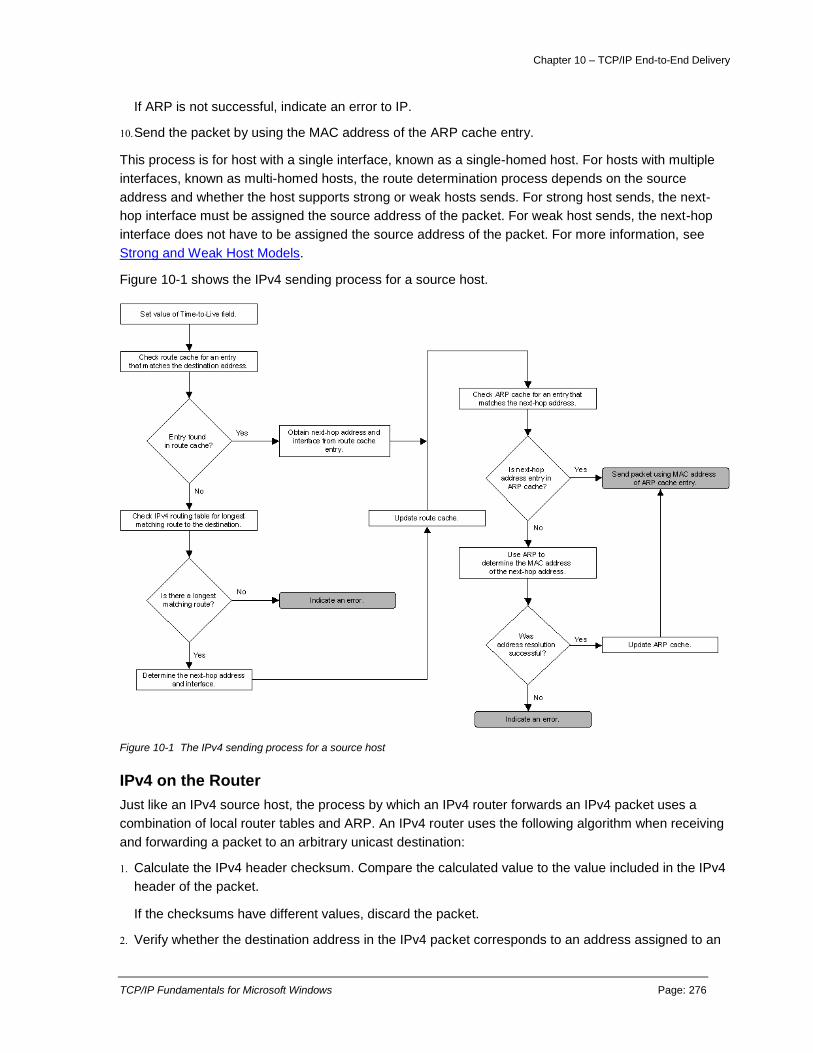
Chapter 10 – TCP/IP End-to-End Delivery
TCP/IP Fundamentals for Microsoft Windows Page: 276
If ARP is not successful, indicate an error to IP.
10. Send the packet by using the MAC address of the ARP cache entry.
This process is for host with a single interface, known as a single-homed host. For hosts with multiple
interfaces, known as multi-homed hosts, the route determination process depends on the source
address and whether the host supports strong or weak hosts sends. For strong host sends, the next-
hop interface must be assigned the source address of the packet. For weak host sends, the next-hop
interface does not have to be assigned the source address of the packet. For more information, see
Strong and Weak Host Models.
Figure 10-1 shows the IPv4 sending process for a source host.
Figure 10-1 The IPv4 sending process for a source host
IPv4 on the Router
Just like an IPv4 source host, the process by which an IPv4 router forwards an IPv4 packet uses a
combination of local router tables and ARP. An IPv4 router uses the following algorithm when receiving
and forwarding a packet to an arbitrary unicast destination:
1. Calculate the IPv4 header checksum. Compare the calculated value to the value included in the IPv4
header of the packet.
If the checksums have different values, discard the packet.
2. Verify whether the destination address in the IPv4 packet corresponds to an address assigned to an

Chapter 10 – TCP/IP End-to-End Delivery
TCP/IP Fundamentals for Microsoft Windows Page: 277
interface of the router.
If so, process the IPv4 packet as the destination host. (See step 3 in "IPv4 on the Destination Host"
in this chapter.)
3. Decrement the value of the TTL field by 1.
If the value of the TTL field is less than 1, send an Internet Control Message Protocol (ICMP) Time
Exceeded-TTL Exceeded in Transit message to the sender, and discard the packet.
If the value of the TTL field is greater than 0, recalculate the Checksum field, and then update the
TTL and the Checksum fields in the IPv4 header of the packet.
4. Check the route cache for an entry that matches the destination address.
5. If the route cache contains an entry that matches the destination address, obtain the next-hop IPv4
address and interface from the entry, and go to step 10.
6. If the route cache does not contain an entry that matches the destination address, check the local
IPv4 routing table for the longest matching route to the destination IPv4 address.
7. Based on the longest matching route, determine the next-hop IPv4 address and interface to use for
forwarding the packet.
If no route is found, send an ICMP Destination Unreachable-Host Unreachable message to the
source host, and discard the packet.
8. Update the route cache with an entry that contains the destination IPv4 address of the packet and its
corresponding next-hop address and interface.
9. Compare the IP maximum transmission unit (MTU) of the next-hop interface to the size of the IPv4
packet being forwarded. If the IP MTU of the next-hop interface is smaller than the packet size, check
the Don’t Fragment (DF) flag in the IPv4 header.
If DF flag is set to 1, send ICMP Destination Unreachable-Fragmentation Needed and DF Set
messages to the source host, and discard the packet.
If DF flag is set to 0, fragment the IPv4 packet payload.
10. Check the ARP cache of the next-hop interface for an entry that matches the next-hop IPv4 address.
11. If the ARP cache contains an entry that matches the next-hop IPv4 address, obtain the
corresponding MAC address, and go to step 13.
12. If the ARP cache does not contain an entry that matches the next-hop IPv4 address, use ARP to
obtain the MAC address for the next-hop IPv4 address.
If ARP is successful, update the ARP cache with an entry that contains the next-hop IP address and
its corresponding MAC address.
If ARP is not successful, send an ICMP Destination Unreachable-Host Unreachable message to the
source host, and discard the packet.
13. Send the packet by using the MAC address of the ARP cache entry.
Figures 10-2 and 10-3 show the router forwarding process.

Chapter 10 – TCP/IP End-to-End Delivery
TCP/IP Fundamentals for Microsoft Windows Page: 278
Figure 10-2 IPv4 router forwarding process (part 1)

Chapter 10 – TCP/IP End-to-End Delivery
TCP/IP Fundamentals for Microsoft Windows Page: 279
Figure 10-3 IPv4 router forwarding process (part 2)
Each IPv4 router in the path between the source host and the destination host repeats this process.
IPv4 on the Destination Host
A destination IPv4 host uses the following algorithm when receiving an IPv4 packet:
1. Calculate the IPv4 header checksum. Compare the calculated value to the value included in the IPv4
header of the packet.
If the checksums have different values, discard the packet.
2. Verify whether the destination address in the IPv4 packet corresponds to an IPv4 address assigned
to a local host interface.
If the destination address is not assigned to a local host interface, discard the packet.
3. Verify that the value of the Protocol field corresponds to an upper layer protocol in use on the host.
If the protocol does not exist, send an ICMP Destination Unreachable-Protocol Unreachable
message back to the sender, and discard the packet.
4. If the upper layer protocol data unit (PDU) is not a Transmission Control Protocol (TCP) segment or
User Datagram Protocol (UDP) message, pass the upper layer PDU to the appropriate protocol.
5. If the upper layer PDU is a TCP segment or UDP message, check the destination port.
If no application is listening on the UDP port number, send an ICMP Destination Unreachable-Port
Unreachable message back to the sender, and discard the packet. If no application is listening on the

Chapter 10 – TCP/IP End-to-End Delivery
TCP/IP Fundamentals for Microsoft Windows Page: 280
TCP port number, send a TCP Connection Reset segment back to the sender, and discard the
packet.
6. For the application listening on the UDP or TCP destination port, process the contents of the TCP
segment or UDP message.
This process is for a single-homed host. For multi-homed hosts, the receive process depends on
whether the host supports strong or weak hosts receives. For strong host receives, the receiving
interface must be assigned the destination address of the packet. For weak host receives, the receiving
interface does not have to be assigned the destination address of the packet. For more information, see
Strong and Weak Host Models.
Figure 10-4 shows the IPv4 receiving process on the destination host.
Figure 10-4 IPv4 receiving process on the destination host
Chapter 10 – TCP/IP End-to-End Delivery
TCP/IP Fundamentals for Microsoft Windows Page: 281
Step-by-Step IPv4 Traffic Example
To show the end-to-end delivery process, this section steps through an example of IPv4 traffic when a
user types the URL of a Web page in the Address bar of a Web browser and views a Web page from a
Web server. This example demonstrates the following aspects of IPv4 traffic:
Name resolution using the Domain Name System (DNS)
End-to-end delivery using a source host, intermediate routers, and a destination host
Creation of a TCP connection, including the three-way TCP handshake
Use of the Hypertext Transfer Protocol (HTTP) to download the Hypertext Markup Language (HTML)
text of a Web page
Network Configuration
Figure 10-5 shows a simple private IPv4 intranet consisting of four subnets connected with three
routers. The example intranet contains a Web client, a DNS server, and a Web server.

Chapter 10 – TCP/IP End-to-End Delivery
TCP/IP Fundamentals for Microsoft Windows Page: 282
Figure 10-5 An example IPv4 intranet
The following sections describe the IPv4 configuration of each of these components.
Web Client
The Web client is a single-homed computer connected to the 10.0.13.0/24 subnet and uses the IPv4
address of 10.0.13.110/24, the default gateway at 10.0.13.1, and the DNS server at 10.0.47.91. The
Web client has the following routes:
10.0.13.0/24 (directly attached network route)
0.0.0.0/0 with the next-hop address of 10.0.13.1 (default route)
Note To simplify the discussion for each component of the example IPv4 intranet, this example lists only
the most relevant routes.

Chapter 10 – TCP/IP End-to-End Delivery
TCP/IP Fundamentals for Microsoft Windows Page: 283
Router 1
Router 1 is connected to the 10.0.13.0/24 subnet using the IPv4 address 10.0.13.1 and the
10.0.21.0/24 subnet using the IPv4 address 10.0.21.1. Router 1 has the following routes:
10.0.13.0/24 (directly attached network route)
10.0.21.0/24 (directly attached network route)
10.0.47.0/24 with the next-hop address of 10.0.21.2
10.0.48.0/24 with the next-hop address of 10.0.21.3
Router 2
Router 2 is connected to the 10.0.21.0/24 subnet using the IPv4 address 10.0.21.2 and the
10.0.47.0/24 subnet using the IPv4 address 10.0.47.1. Router 2 has the following routes:
10.0.21.0/24 (directly attached network route)
10.0.47.0/24 (directly attached network route)
10.0.13.0/24 with the next-hop address of 10.0.21.1
10.0.48.0/24 with the next-hop address of 10.0.21.3
Router 3
Router 3 is connected to the 10.0.21.0/24 subnet using the IPv4 address 10.0.21.3 and the
10.0.48.0/24 subnet using the IPv4 address 10.0.48.1. Router 3 has the following routes:
10.0.21.0/24 (directly attached network route)
10.0.48.0/24 (directly attached network route)
10.0.13.0/24 with the next-hop address of 10.0.21.1
10.0.47.0/24 with the next-hop address of 10.0.21.2
DNS Server
The DNS server is a single-homed computer connected to the 10.0.47.0/24 subnet and uses the IPv4
address of 10.0.47.91/24 and the default gateway of 10.0.47.1. The DNS server has the following
routes:
10.0.47.0/24 (directly attached network route)
0.0.0.0/0 with the next-hop address of 10.0.47.1
The DNS server has an Address (A) resource record that maps the name web1.example.com to the
IPv4 address of 10.0.48.12.
Web Server
The Web server is a single-homed computer connected to the 10.0.48.0/24 subnet and uses the IPv4
address of 10.0.48.12/24, the default gateway of 10.0.48.1, and the DNS server of 10.0.47.91. The
Web server has the following routes:

Chapter 10 – TCP/IP End-to-End Delivery
TCP/IP Fundamentals for Microsoft Windows Page: 284
10.0.48.0/24 (directly attached network route)
0.0.0.0/0 with the next-hop address of 10.0.48.1
Web Traffic Example
This example assumes the following:
The ARP and route caches on all of the components of the network are empty.
The DNS client resolver cache on the Web client is empty.
The Web browser on the Web client has not cached the contents of the Web page on the Web server.
In this example, a user on the Web client runs a Web browser, types the address
http://web1.example.com/example.htm in the Web browser's Address bar, and presses ENTER. The
computers on this example intranet send the following set of messages:
1. The Web client sends a DNS Name Query Request message to the DNS server.
2. The DNS server sends a DNS Name Query Response message to the Web client.
3. The Web client sends a TCP Synchronize (SYN) segment to the Web server.
4. The Web server sends a TCP SYN-Acknowledgement (ACK) segment to the Web client.
5. The Web client sends a TCP ACK segment to the Web server.
6. The Web client sends an HTTP Get message to the Web server.
7. The Web server sends an HTTP Get-Response message to the Web client.
The following sections describe the end-to-end delivery of each of these messages.
DNS Name Query Request Message to the DNS Server
The following process occurs when the Web client sends the DNS Name Query Request message to
the DNS server:
1. The Web browser parses the address in the Address bar and uses a Windows Sockets
getaddrinfo()or gethostbyname()function to attempt to resolve the name web1.example.com to its
IPv4 address. For this example, the DNS server is only storing a single A record for the name
web1.example.com.
2. The Web client constructs a DNS Name Query Request message with the source IPv4 address of
10.0.13.110 and the destination IPv4 address of 10.0.47.91.
3. The Web client checks its route cache for an entry for the IPv4 address of 10.0.47.91 and does not
find a match.
4. The Web client performs the route determination process to find the closest matching route for the
destination IPv4 address of 10.0.47.91. The default route (0.0.0.0/0) is the closest matching route.
The Web client sets the next-hop IPv4 address to 10.0.13.1 and the next-hop interface to the network
adapter that is attached to the 10.0.13.0/24 subnet.
5. The Web client updates its route cache with an entry for 10.0.47.91 with the next-hop IPv4 address of
10.0.13.1 and the next-hop interface of the network adapter that is attached to the 10.0.13.0/24
subnet.

Chapter 10 – TCP/IP End-to-End Delivery
TCP/IP Fundamentals for Microsoft Windows Page: 285
6. The Web client checks its ARP cache for an entry with the IPv4 address of 10.0.13.1 and does not
find a match.
7. The Web client broadcasts an ARP Request message, querying all nodes on the 10.0.13.0/24 subnet
for the MAC address of the interface that is assigned the IPv4 address of 10.0.13.1.
8. Router 1 receives the ARP Request message. Because Router 1 is assigned the IPv4 address of
10.0.13.1, that router adds an entry to its ARP cache for the IPv4 address 10.0.13.110 and the MAC
address of the Web client's interface on the 10.0.13.0/24 subnet.
9. Router 1 sends a unicast ARP Reply message to the Web client.
10. The Web client updates its ARP cache with an entry for the IPv4 address of 10.0.13.1 and the MAC
address of Router 1's interface on the 10.0.13.0/24 subnet.
11. The Web client sends the unicast DNS Name Query Request message destined for 10.0.47.91 to the
MAC address of Router 1's interface on the 10.0.13.0/24 subnet.
12. Router 1 receives the DNS Name Query Request message.
13. Router 1 checks its route cache for an entry for 10.0.47.91 and does not find a match.
14. Router 1 performs the route determination process for the destination address 10.0.47.91. The
closest matching route is the route for 10.0.47.0/24. Router 1 sets the next-hop address to 10.0.21.2
and the next-hop interface to the network adapter that is attached to the 10.0.21.0/24 subnet.
15. Router 1 updates its route cache with an entry for 10.0.47.91 with the next-hop IPv4 address of
10.0.21.2 and the next-hop interface of the network adapter that is attached to the 10.0.21.0/24
subnet.
16. Router 1 checks its ARP cache for an entry with the IPv4 address of 10.0.21.2 and does not find a
match.
17. Router 1 broadcasts an ARP Request message, querying all nodes on the 10.0.21.0/24 subnet for
the MAC address of the interface that is assigned the IPv4 address of 10.0.21.2.
18. Router 2 receives the ARP Request message. Because it is assigned the IPv4 address of 10.0.21.2,
Router 2 adds an entry to its ARP cache for the IPv4 address 10.0.21.1 and the MAC address of
Router 1's interface on the 10.0.21.0/24 subnet.
19. Router 2 sends a unicast ARP Reply message to Router 1.
20. Router 1 updates its ARP cache with an entry for the IPv4 address of 10.0.21.2 and the MAC
address of Router 2's interface on the 10.0.21.0/24 subnet.
21. Router 1 forwards the unicast DNS Name Query Request message destined for 10.0.47.91 to Router
2's MAC address on the 10.0.21.0/24 subnet.
22. Router 2 receives the DNS Name Query Request message.
23. Router 2 checks its route cache for an entry for 10.0.47.91 and does not find a match.
24. Router 2 performs the route determination process for the destination address 10.0.47.91. The
closest matching route is the route for 10.0.47.0/24 (a directly attached network route). Router 2 sets
the next-hop address to the packet's destination address of 10.0.47.91 and the next-hop interface to
the network adapter that is attached to the 10.0.47.0/24 subnet.

Chapter 10 – TCP/IP End-to-End Delivery
TCP/IP Fundamentals for Microsoft Windows Page: 286
25. Router 2 updates its route cache with an entry for 10.0.47.91 with the next-hop IPv4 address of
10.0.47.91 and the next-hop interface of the network adapter that is attached to the 10.0.47.0/24
subnet.
26. Router 2 checks its ARP cache for an entry with the IPv4 address of 10.0.47.91 and does not find a
match.
27. Router 2 broadcasts an ARP Request message, querying all nodes on the 10.0.47.0/24 subnet for
the MAC address of the interface that is assigned the IPv4 address of 10.0.47.91.
28. The DNS server receives the ARP Request message. Because the DNS server is assigned the IPv4
address of 10.0.47.91, the server adds an entry to its ARP cache for the IPv4 address 10.0.47.1 and
the MAC address of Router 2's interface on the 10.0.47.0/24 subnet.
29. The DNS server sends a unicast ARP Reply message to Router 2.
30. Router 2 updates its ARP cache with an entry for the IPv4 address of 10.0.47.91 and the MAC
address of the DNS server's interface on the 10.0.47.0/24 subnet.
31. Router 2 forwards the unicast DNS Name Query Request message destined for 10.0.47.91 to the
MAC address of the DNS server's interface on the 10.0.47.0/24 subnet.
32. The DNS server receives the packet and passes the DNS Name Query Request message to the
DNS Server service.
33. The DNS Server service finds the A record for the name web1.example.com and resolves it to the
IPv4 address of 10.0.48.12.
For the end-to-end delivery of the DNS Name Query Request message, the following has occurred:
The Web client sent the DNS Name Query Request message, and Router 1 and Router 2 forwarded it
over the 10.0.13.0/24, 10.0.21.0/24, and 10.0.47.0/24 subnets to the DNS server.
The Web client's route cache has an entry for 10.0.47.91. The Web client's ARP cache has an entry for
10.0.13.1.
Router 1's route cache has an entry for 10.0.47.91. Router 1's ARP cache has entries for 10.0.13.110
and 10.0.21.2.
Router 2's route cache has an entry for 10.0.47.91. Router 2's ARP cache has entries for 10.0.21.1 and
10.0.47.91.
The DNS server's ARP cache has an entry for 10.0.47.1.
DNS Name Query Response Message to the Web Client
When the DNS server sends the DNS Name Query Response message to the Web client, the following
process occurs:
1. The DNS Server service constructs a DNS Name Query Response message with the source IPv4
address of 10.0.47.91 and the destination IPv4 address of 10.0.13.110.
2. The DNS server checks its route cache for an entry for the IPv4 address of 10.0.13.110 and does not
find a match.
3. The DNS server performs the route determination process to find the closest matching route for the
Chapter 10 – TCP/IP End-to-End Delivery
TCP/IP Fundamentals for Microsoft Windows Page: 287
destination IPv4 address of 10.0.13.110. The default route (0.0.0.0/0) is the closest matching route.
The DNS server set the next-hop IPv4 address to 10.0.47.1 and the next-hop interface to the network
adapter attached to the 10.0.47.0/24 subnet.
4. The DNS server updates its route cache with an entry for 10.0.13.110 with the next-hop IPv4 address
of 10.0.47.1 and the next-hop interface of the network adapter that is attached to the 10.0.47.0/24
subnet.
5. The DNS server checks its ARP cache for an entry with the IPv4 address of 10.0.47.1 and finds a
match.
6. Using the ARP cache entry for 10.0.47.1, the DNS server sends the unicast DNS Name Query
Response message destined for 10.0.13.110 to the MAC address of Router 2's interface on the
10.0.47.0/24 subnet.
7. Router 2 receives the DNS Name Query Response message.
8. Router 2 checks its route cache for an entry for 10.0.13.110 and does not find a match.
9. Router 2 performs the route determination process for the destination address 10.0.13.110. The
closest matching route is the route for 10.0.13.0/24. Router 2 sets the next-hop address to 10.0.21.1
and the next-hop interface to the network adapter that is attached to the 10.0.21.0/24 subnet.
10. Router 2 updates its route cache with an entry for 10.0.13.110 with the next-hop IPv4 address of
10.0.21.1 and the next-hop interface of the network adapter that is attached to the 10.0.21.0/24
subnet.
11. Router 2 checks its ARP cache for an entry with the IPv4 address of 10.0.21.1 and finds a match.
12. Using the ARP cache entry for 10.0.21.1, Router 2 forwards the unicast DNS Name Query Response
message destined for 10.0.13.110 to Router 1's MAC address on the 10.0.21.0/24 subnet.
13. Router 1 receives the DNS Name Query Response message.
14. Router 1 checks its route cache for an entry for 10.0.13.110 and does not find a match.
15. Router 1 performs the route determination process for the destination address 10.0.13.110. The
closest matching route is the route for 10.0.13.0/24 (a directly attached network route). Router 1 sets
the next-hop address to the packet's destination address of 10.0.13.110 and the next-hop interface to
the network adapter that is attached to the 10.0.13.0/24 subnet.
16. Router 1 updates its route cache with an entry for 10.0.13.110 with the next-hop IPv4 address of
10.0.13.110 and the next-hop interface of the network adapter that is attached to the 10.0.13.0/24
subnet.
17. Router 1 checks its ARP cache for an entry with the IPv4 address of 10.0.13.110 and finds a match.
18. Using the ARP cache entry for 10.0.13.110, Router 1 forwards the unicast DNS Name Query
Response message destined for 10.0.13.110 to the MAC address of the Web client's interface on the
10.0.13.0/24 subnet.
19. The Web client receives the packet and passes the DNS Name Query Response message to the
DNS Client service.
20. The DNS Client service on the Web client passes the resolved IPv4 address of 10.0.48.12 to
Windows Sockets.

Chapter 10 – TCP/IP End-to-End Delivery
TCP/IP Fundamentals for Microsoft Windows Page: 288
21. Windows Sockets passes the resolved IPv4 address of 10.0.48.12 to the Web browser.
For the end-to-end delivery of the DNS Name Query Response message, the following has occurred:
The DNS server sent the DNS Name Query Response message, and Router 2 and Router 1 forwarded
it over the 10.0.47.0/24, 10.0.21.0/24, and 10.0.13.0/24 subnets to the Web client.
The DNS server's route cache has a new entry for 10.0.13.110.
Router 2's route cache has a new entry for 10.0.13.110.
Router 1's route cache has a new entry for 10.0.13.110.
TCP SYN Segment to the Web Server
Now that the Web server's name has been resolved to an IPv4 address, the Web client must establish
a TCP connection with the Web server. TCP connections are initiated through a three-way handshake
consisting of the following:
A TCP SYN segment that the Web client sends
A TCP SYN-ACK segment that the Web server sends
A TCP ACK segment that the Web client sends
When the Web client sends the TCP SYN segment to the Web server, the following process occurs:
1. The Web browser, upon obtaining the resolved address of 10.0.48.12 from Windows Sockets, uses a
Windows Sockets connect() function to create a TCP connection between the Web client and the
Web server.
2. The Web client constructs a TCP SYN segment with the source IPv4 address of 10.0.13.110 and the
destination IPv4 address of 10.0.48.12.
3. The Web client checks its route cache for an entry for the IPv4 address of 10.0.48.12 and does not
find a match.
4. The Web client performs the route determination process to find the closest matching route for the
destination IPv4 address of 10.0.48.12. The default route (0.0.0.0/0) is the closest matching route.
The Web client sets the next-hop IPv4 address to 10.0.13.1 and the next-hop interface to the network
adapter attached to the 10.0.13.0/24 subnet.
5. The Web client updates its route cache with an entry for 10.0.48.12 with the next-hop IPv4 address of
10.0.13.1 and the next-hop interface of the network adapter that is attached to the 10.0.13.0/24
subnet.
6. The Web client checks its ARP cache for an entry with the IPv4 address of 10.0.13.1 and finds a
match.
7. Using the ARP cache entry for 10.0.13.1, the Web client sends the unicast TCP SYN segment
destined for 10.0.48.12 to the MAC address of Router 1's interface on the 10.0.13.0/24 subnet.
8. Router 1 receives the TCP SYN segment.
9. Router 1 checks its route cache for an entry for 10.0.48.12 and does not find a match.
10. Router 1 performs the route determination process for the destination address 10.0.48.12. The
Chapter 10 – TCP/IP End-to-End Delivery
TCP/IP Fundamentals for Microsoft Windows Page: 289
closest matching route is the route for 10.0.48.0/24. Router 1 sets the next-hop address to 10.0.21.3
and the next-hop interface to the network adapter that is attached to the 10.0.21.0/24 subnet.
11. Router 1 updates its route cache with an entry for 10.0.48.12 with the next-hop IPv4 address of
10.0.21.3 and the next-hop interface of the network adapter that is attached to the 10.0.21.0/24
subnet.
12. Router 1 checks its ARP cache for an entry with the IPv4 address of 10.0.21.3 and does not find a
match.
13. Router 1 broadcasts an ARP Request message, querying all nodes on the 10.0.21.0/24 subnet for
the MAC address of the interface that is assigned the IPv4 address of 10.0.21.3.
14. Router 3 receives the ARP Request message. Because it is assigned the IPv4 address of 10.0.21.3,
Router 3 adds an entry to its ARP cache for the IPv4 address 10.0.21.1 and the MAC address of
Router 1's interface on the 10.0.21.0/24 subnet.
15. Router 3 sends a unicast ARP Reply message to Router 1.
16. Router 1 updates its ARP cache with an entry for the IPv4 address of 10.0.21.3 and the MAC
address of Router 3's interface on the 10.0.21.0/24 subnet.
17. Router 1 forwards the unicast TCP SYN segment destined for 10.0.48.12 to Router 3's MAC address
on the 10.0.21.0/24 subnet.
18. Router 3 receives the TCP SYN segment.
19. Router 3 checks its route cache for an entry for 10.0.48.12 and does not find a match.
20. Router 3 performs the route determination process for the destination address 10.0.48.12. The
closest matching route is the route for 10.0.48.0/24 (a directly attached network route). Router 3 sets
the next-hop address to the packet's destination address of 10.0.48.12 and the next-hop interface to
the network adapter that is attached to the 10.0.48.0/24 subnet.
21. Router 3 updates its route cache with an entry for 10.0.48.12 with the next-hop IPv4 address of
10.0.48.12 and the next-hop interface of the network adapter that is attached to the 10.0.48.0/24
subnet.
22. Router 3 checks its ARP cache for an entry with the IPv4 address of 10.0.48.12 and does not find a
match.
23. Router 3 broadcasts an ARP Request message, querying all nodes on the 10.0.48.0/24 subnet for
the MAC address of the interface that is assigned the IPv4 address of 10.0.48.12.
24. The Web server receives the ARP Request message. Because it is assigned the IPv4 address of
10.0.48.12, the Web server adds an entry to its ARP cache for the IPv4 address 10.0.48.1 and the
MAC address of Router 3's interface on the 10.0.48.0/24 subnet.
25. The Web server sends a unicast ARP Reply message to Router 3.
26. Router 3 updates its ARP cache with an entry for the IPv4 address of 10.0.48.12 and the MAC
address of the Web server's interface on the 10.0.48.0/24 subnet.
27. Router 3 forwards the unicast TCP SYN segment destined for 10.0.48.12 to the MAC address of the
Web server's interface on the 10.0.48.0/24 subnet.

Chapter 10 – TCP/IP End-to-End Delivery
TCP/IP Fundamentals for Microsoft Windows Page: 290
28. The Web server receives the TCP SYN segment.
For the end-to-end delivery of the TCP SYN segment, the following has occurred:
The Web client sent the TCP SYN segment, and Router 1 and Router 3 forwarded it over the
10.0.13.0/24, 10.0.21.0/24, and 10.0.48.0/24 subnets to the Web server.
The Web client's route cache has a new entry for 10.0.48.12.
Router 1's route cache has a new entry for 10.0.48.12. Router 1's ARP cache has a new entry for
10.0.21.3.
Router 3's route cache has an entry for 10.0.48.12. Router 3's ARP cache has entries for 10.0.21.1 and
10.0.48.12.
The Web server's ARP cache has an entry for 10.0.48.1.
TCP SYN-ACK Segment to the Web Client
When the Web server sends the TCP SYN-ACK segment to the Web client, the following process
occurs:
1. The Web server constructs a TCP SYN-ACK segment with the source IPv4 address of 10.0.48.12
and the destination IPv4 address of 10.0.13.110.
2. The Web server checks its route cache for an entry for the IPv4 address of 10.0.13.110 and does not
find a match.
3. The Web server performs the route determination process to find the closest matching route for the
destination IPv4 address of 10.0.13.110. The default route (0.0.0.0/0) is the closest matching route.
The Web server sets the next-hop IPv4 address to 10.0.48.1 and the next-hop interface to the
network adapter that is attached to the 10.0.48.0/24 subnet.
4. The Web server updates its route cache with an entry for 10.0.13.110 with the next-hop IPv4 address
of 10.0.48.1 and the next-hop interface of the network adapter that is attached to the 10.0.48.0/24
subnet.
5. The Web server checks its ARP cache for an entry with the IPv4 address of 10.0.48.1 and finds a
match.
6. Using the ARP cache entry for 10.0.48.1, the Web server sends the unicast TCP SYN-ACK segment
destined for 10.0.13.110 to the MAC address of Router 3's interface on the 10.0.48.0/24 subnet.
7. Router 3 receives the TCP SYN-ACK segment.
8. Router 3 checks its route cache for an entry for 10.0.13.110 and does not find a match.
9. Router 3 performs the route determination process for the destination address 10.0.13.110. The
closest matching route is the route for 10.0.13.0/24. Router 3 sets the next-hop address to 10.0.21.1
and the next-hop interface to the network adapter that is attached to the 10.0.21.0/24 subnet.
10. Router 3 updates its route cache with an entry for 10.0.13.110 with the next-hop IPv4 address of
10.0.21.1 and the next-hop interface of the network adapter that is attached to the 10.0.21.0/24
subnet.
11. Router 3 checks its ARP cache for an entry with the IPv4 address of 10.0.21.1 and finds a match.

Chapter 10 – TCP/IP End-to-End Delivery
TCP/IP Fundamentals for Microsoft Windows Page: 291
12. Using the ARP cache entry for 10.0.21.1, Router 3 forwards the unicast TCP SYN-ACK segment
destined for 10.0.13.110 to Router 1's MAC address on the 10.0.21.0/24 subnet.
13. Router 1 receives the TCP SYN-ACK segment.
14. Router 1 checks its route cache for an entry for 10.0.13.110 and finds a match.
15. Using the route cache entry for 10.0.13.110, Router 1 sets the next-hop address to 10.0.13.110 and
the next-hop interface to the network adapter that is attached to the 10.0.13.0/24 subnet.
16. Router 1 checks its ARP cache for an entry with the IPv4 address of 10.0.13.110 and finds a match.
17. Using the ARP cache entry for 10.0.13.110, Router 1 forwards the unicast TCP SYN-ACK segment
destined for 10.0.13.110 to the MAC address of the Web client's interface on the 10.0.13.0/24
subnet.
18. The Web client receives the TCP SYN-ACK segment.
For the end-to-end delivery of the TCP SYN-ACK segment, the following has occurred:
The Web server sent the TCP SYN-ACK segment, and Router 3 and Router 1 forwarded it over the
10.0.48.0/24, 10.0.21.0/24, and 10.0.13.0/24 subnets to the Web client.
The Web server's route cache has a new entry for 10.0.13.110.
Router 3's route cache has a new entry for 10.0.13.110.
TCP ACK Segment to the Web Server
When the Web client sends the TCP ACK segment to the Web server, the following process occurs:
1. The Web client constructs a TCP ACK segment message with the source IPv4 address of
10.0.13.110 and the destination IPv4 address of 10.0.48.12.
2. The Web client checks its route cache for an entry for the IPv4 address of 10.0.48.12 and finds a
match.
3. Using the route cache entry for 10.0.48.12, the Web client sets the next-hop address to 10.0.13.1
and the next-hop interface to the network adapter that is attached to the 10.0.13.0/24 subnet.
4. The Web client checks its ARP cache for an entry with the IPv4 address of 10.0.13.1 and finds a
match.
5. Using the ARP cache entry for 10.0.13.1, the Web client sends the unicast TCP ACK segment
destined for 10.0.48.12 to the MAC address of Router 1's interface on the 10.0.13.0/24 subnet.
6. Router 1 receives the TCP ACK segment, checks its route cache for an entry for 10.0.48.12, and
finds a match.
7. Using the route cache entry for 10.0.48.12, Router 1 sets the next-hop address to 10.0.21.3 and the
next-hop interface to the network adapter that is attached to the 10.0.21.0/24 subnet.
8. Router 1 checks its ARP cache for an entry with the IPv4 address of 10.0.21.3 and finds a match.
9. Using the ARP cache entry for 10.0.21.3, Router 1 forwards the unicast TCP ACK segment destined
for 10.0.48.12 to Router 3's MAC address on the 10.0.21.0/24 subnet.
10. Router 3 receives the TCP ACK segment, checks its route cache for an entry for 10.0.48.12, and

Chapter 10 – TCP/IP End-to-End Delivery
TCP/IP Fundamentals for Microsoft Windows Page: 292
finds a match.
11. Using the route cache entry for 10.0.48.12, Router 3 sets the next-hop address to the packet's
destination address of 10.0.48.12 and the next-hop interface to the network adapter that is attached
to the 10.0.48.0/24 subnet.
12. Router 3 checks its ARP cache for an entry with the IPv4 address of 10.0.48.12 and finds a match.
13. Using the ARP cache entry for 10.0.48.12, Router 3 forwards the unicast TCP ACK segment
destined for 10.0.48.12 to the MAC address of the Web server's interface on the 10.0.47.0/24 subnet.
14. The Web server receives the TCP ACK segment.
15. Windows Sockets indicates to the Web browser that the requested TCP connection is complete.
The Web client sent the TCP ACK segment, which Router 1 and Router 3 forwarded over the
10.0.13.0/24, 10.0.21.0/24, and 10.0.48.0/24 subnets to the Web server.
HTTP Get Message to the Web Server
To download the contents of a Web page, a Web browser sends an HTTP Get message containing the
name of the page. When the Web client sends the HTTP Get message to the Web server, the following
process occurs:
1. When the Web browser receives the indication that the TCP connection is complete, the browser
constructs an HTTP Get message that requests the contents of the Web page from the Web server.
In the message, the source IPv4 address is 10.0.13.110, and the destination IPv4 address is
10.0.48.12.
2. The Web client checks its route cache for an entry for the IPv4 address of 10.0.48.12 and finds a
match.
3. Using the route cache entry for 10.0.48.12, the Web client sets the next-hop address to 10.0.13.1
and the next-hop interface to the network adapter that is attached to the 10.0.13.0/24 subnet.
4. The Web client checks its ARP cache for an entry with the IPv4 address of 10.0.13.1 and finds a
match.
5. Using the ARP cache entry for 10.0.13.1, the Web client sends the unicast HTTP Get message
destined for 10.0.48.12 to the MAC address of Router 1's interface on the 10.0.13.0/24 subnet.
6. Router 1 receives the HTTP Get message, checks its route cache for an entry for 10.0.48.12, and
finds a match.
7. Using the route cache entry for 10.0.48.12, Router 1 sets the next-hop address to 10.0.21.3 and the
next-hop interface to the network adapter that is attached to the 10.0.21.0/24 subnet.
8. Router 1 checks its ARP cache for an entry with the IPv4 address of 10.0.21.3 and finds a match.
9. Using the ARP cache entry for 10.0.21.3, Router 1 forwards the unicast HTTP Get message destined
for 10.0.48.12 to Router 3's MAC address on the 10.0.21.0/24 subnet.
10. Router 3 receives the HTTP Get message, checks its route cache for an entry for 10.0.48.12, and
finds a match.
11. Using the route cache entry for 10.0.48.12, Router 3 sets the next-hop address to the packet's

Chapter 10 – TCP/IP End-to-End Delivery
TCP/IP Fundamentals for Microsoft Windows Page: 293
destination address of 10.0.48.12 and the next-hop interface to the network adapter that is attached
to the 10.0.48.0/24 subnet.
12. Router 3 checks its ARP cache for an entry with the IPv4 address of 10.0.48.12 and finds a match.
13. Using the ARP cache entry for 10.0.48.12, Router 3 forwards the unicast HTTP Get message
destined for 10.0.48.12 to the MAC address of the Web server's interface on the 10.0.47.0/24 subnet.
14. The Web server receives the HTTP Get message.
The Web client sent the HTTP Get message, which Router 1 and Router 3 forwarded over the
10.0.13.0/24, 10.0.21.0/24, and 10.0.48.0/24 subnets to the Web server.
HTTP Get-Response Message to the Web Client
The response to an HTTP Get message is an HTTP Get-Response message containing the HTML text
of the Web page. To simplify this example, assume that the entire Web page can fit within a single TCP
segment. When the Web server sends the HTTP Get-Response message to the Web client, the
following occurs:
1. The Web server constructs an HTTP Get-Response message with the source IPv4 address of
10.0.48.12 and the destination IPv4 address of 10.0.13.110.
2. The Web server checks its route cache for an entry for the IPv4 address of 10.0.13.110 and finds a
match.
3. Using the route cache entry for 10.0.13.110, the Web server sets the next-hop IPv4 address to
10.0.48.1 and the next-hop interface to the network adapter attached to the 10.0.48.0/24 subnet.
4. The Web server checks its ARP cache for an entry with the IPv4 address of 10.0.48.1 and finds a
match.
5. Using the ARP cache entry for 10.0.48.1, the Web server sends the unicast HTTP Get-Response
message destined for 10.0.13.110 to the MAC address of Router 3's interface on the 10.0.48.0/24
subnet.
6. Router 3 receives the HTTP Get-Response message.
7. Router 3 checks its route cache for an entry for 10.0.13.110 and finds a match.
8. Using the route cache entry for 10.0.13.110, Router 3 sets the next-hop address to 10.0.21.1 and the
next-hop interface to the network adapter that is attached to the 10.0.21.0/24 subnet.
9. Router 3 checks its ARP cache for an entry with the IPv4 address of 10.0.21.1 and finds a match.
10. Using the ARP cache entry for 10.0.21.1, Router 3 forwards the unicast HTTP Get-Response
message destined for 10.0.13.110 to Router 1's MAC address on the 10.0.21.0/24 subnet.
11. Router 1 receives the HTTP Get-Response message.
12. Router 1 checks its route cache for an entry for 10.0.13.110 and finds a match.
13. Using the route cache entry for 10.0.13.110, Router 1 sets the next-hop address to 10.0.13.110 and
the next-hop interface to the network adapter that is attached to the 10.0.13.0/24 subnet.
14. Router 1 checks its ARP cache for an entry with the IPv4 address of 10.0.13.110 and finds a match.

Chapter 10 – TCP/IP End-to-End Delivery
TCP/IP Fundamentals for Microsoft Windows Page: 294
15. Using the ARP cache entry for 10.0.13.110, Router 1 forwards the unicast HTTP Get-Response
message destined for 10.0.13.110 to the MAC address of the Web client's interface on the
10.0.13.0/24 subnet.
16. The Web client receives the HTTP Get-Response message.
17. The Web browser constructs the visual representation of the Web page at
http://web1.example.com/example.htm.
The Web server sent the HTTP Get-Response message, which Router 3 and Router 1 forwarded over
the 10.0.48.0/24, 10.0.21.0/24, and 10.0.13.0/24 subnets to the Web client.

Chapter 10 – TCP/IP End-to-End Delivery
TCP/IP Fundamentals for Microsoft Windows Page: 295
End-to-End IPv6 Delivery Process
Similar to IPv4, the end-to-end delivery process for IPv6 traffic consists of the following:
The source host sends the packet either to a router or to the final destination (if the destination is a
neighbor).
The router forwards the packet either to another router or to the final destination (if the destination is a
neighbor).
The destination host receives the packet and passes the data to the appropriate application.
Note The following processes assume that the IPv6 header contains no extension headers.
IPv6 on the Source Host
The process by which an IPv6 host sends an IPv6 packet depends on a combination of the local host
data structures and the Neighbor Discovery protocol. An IPv6 host uses the following algorithm when
sending a packet to an arbitrary destination:
1. Specify either a default or application-specified value for the Hop Limit field.
2. Check the destination cache for an entry that matches the destination address. The destination
cache is a table that stores the next-hop IPv6 addresses and interfaces for destinations to which
traffic has been recently sent. You can view the destination cache with the netsh interface ipv6
show destinationcache command.
3. If the destination cache contains an entry that matches the destination address, obtain the next-hop
address and interface index from the destination cache entry, and go to step 7.
4. Check the local IPv6 routing table for the longest matching route with the lowest metric to the
destination address. If multiple longest matching routes have the lowest metric, choose a route to
use.
5. Based on chosen route, determine the next-hop interface and address used for forwarding the
packet.
6. If no route is found, assume that the destination is directly reachable and sets the next-hop IPv6
address to the destination address and chooses an interface.
7. Update the destination cache.
8. Check the neighbor cache for an entry that matches the next-hop address. The neighbor cache
stores neighboring IPv6 addresses and their corresponding MAC address. You can view the
neighbor cache with the netsh interface ipv6 show neighbors command.
9. If the neighbor cache contains an entry that matches the next-hop address, obtain the link-layer
address.
10. If the neighbor cache does not contain an entry that matches the next-hop address, use address
resolution (an exchange of multicast Neighbor Solicitation and unicast Neighbor Advertisement
messages) to obtain the link-layer address for the next-hop address.
11. If address resolution fails, indicate an error.

Chapter 10 – TCP/IP End-to-End Delivery
TCP/IP Fundamentals for Microsoft Windows Page: 296
12. Send the packet by using the link-layer address of the neighbor cache entry.
This process is for a single-homed host. For multi-homed hosts, the route determination process
depends on the source address and whether the host supports strong or weak hosts sends. For strong
host sends, the next-hop interface must be assigned the source address of the packet. For weak host
sends, the next-hop interface does not have to be assigned the source address of the packet.
Figure 10-6 shows the IPv6 sending process for a source host.
Figure 10-6 The IPv6 sending process for a source host
IPv6 on the Router
An IPv6 router uses the following algorithm when it receives and forwards a packet to an arbitrary
unicast or anycast destination:
1. Perform optional header error checks such as ensuring that the value of the Version field is 6 and
that the source address is not the loopback address (::1) or a multicast address.
2. Verify whether the destination address in the IPv6 packet corresponds to an address that is assigned
to a router interface.
If so, process the IPv6 packet as the destination host. (See step 3 in "IPv6 on the Destination Host"
in this chapter.)
3. Decrement the value of the Hop Limit field by 1.

Chapter 10 – TCP/IP End-to-End Delivery
TCP/IP Fundamentals for Microsoft Windows Page: 297
If the value of the Hop Limit field is less than 1, send an Internet Control Message Protocol for IPv6
(ICMPv6) Time Exceeded-Hop Limit Exceeded in Transit message to the sender, and discard the
packet.
4. If the value of the Hop Limit field is greater than 0, update the Hop Limit field in the IPv6 header of
the packet.
5. Check the destination cache for an entry that matches the destination address.
6. If the destination cache contains an entry that matches the destination address, obtain the next-hop
IPv6 address and interface from the destination cache entry, and go to step 10.
7. Check the local IPv6 routing table for the longest matching route to the destination IPv6 address.
8. Based on the longest matching route, determine the next hop IPv6 address and interface to use for
forwarding the packet.
If no route is found, send an ICMPv6 Destination Unreachable-No Route to Destination message to
the source host, and discard the packet.
9. Update the destination cache.
10. If the interface on which the packet was received is the same as the interface on which the packet is
being forwarded, the interface is a point-to-point link, and the Destination Address field matches a
prefix assigned to the interface, send an ICMPv6 Destination Unreachable-Address Unreachable
message to the source host, and discard the packet. This step prevents the needless circular
forwarding of IPv6 packets between the two interfaces on a point-to-point link for a packet whose
destination matches the prefix of the point-to-point link but does not match the address of either
interface.
11. If the interface on which the packet was received is the same as the interface on which the packet is
being forwarded and the Source Address field matches a prefix assigned to the interface, send a
Redirect message to the source host.
12. Compare the IP MTU of the next-hop interface to the size of the IPv6 packet being forwarded.
If the IP MTU of the next-hop interface is smaller than the packet size, send an ICMPv6 Packet Too
Big message to the source host, and discard the packet.
13. Check the neighbor cache for an entry that matches the next-hop IPv6 address.
14. If the neighbor cache contains an entry that matches the next-hop IPv6 address, obtain the link-layer
address.
15. If the neighbor cache does not contain an entry that matches the next-hop address, use address
resolution to obtain the link-layer address for the next-hop address.
If address resolution fails, send an ICMPv6 Destination Unreachable-Address Unreachable message
to the source host, and discard the packet.
16. Send the packet by using the link-layer address of the neighbor cache entry.
Figures 10-7 and 10-8 show the IPv6 router forwarding process.

Chapter 10 – TCP/IP End-to-End Delivery
TCP/IP Fundamentals for Microsoft Windows Page: 298
Figure 10-7 IPv6 router forwarding process (part 1)

Chapter 10 – TCP/IP End-to-End Delivery
TCP/IP Fundamentals for Microsoft Windows Page: 299
Figure 10-8 IPv6 router forwarding process (part 2)
Each IPv6 router in the path between the source host and the destination host repeats this process.
IPv6 on the Destination Host
A destination IPv6 host uses the following algorithm when it receives an IPv6 packet:
1. Perform optional header error checks such as ensuring that the value of the Version field is 6 and
that the source address is not the loopback address (::1) or a multicast address.
2. Verify whether the destination address in the IPv6 packet corresponds to an IPv6 address that is
assigned to a local host interface.
If the destination address is not assigned to a local host interface, discard the IPv6 packet.
3. Verify that the value of the Next Header field corresponds to an upper layer protocol in use on the
host.
If the protocol does not exist, send an ICMPv6 Parameter Problem-Unrecognized Next Header Type
Encountered message back to the sender, and discard the packet.
4. If the upper layer PDU is not a TCP segment or UDP message, pass the upper layer PDU to the
appropriate protocol.
5. If the upper layer PDU is a TCP segment or UDP message, check the destination port.

Chapter 10 – TCP/IP End-to-End Delivery
TCP/IP Fundamentals for Microsoft Windows Page: 300
If no application exists for the UDP port number, send an ICMPv6 Destination Unreachable-Port
Unreachable message back to the sender, and discard the packet. If no application exists for the
TCP port number, send a TCP Connection Reset segment back to the sender, and discard the
packet.
6. If an application exists for the UDP or TCP destination port, process the contents of the TCP
segment or UDP message.
This process is for a single-homed host. For multi-homed hosts, the receive process depends on
whether the host supports strong or weak hosts receives. For strong host receives, the receiving
interface must be assigned the destination address of the packet. For weak host receives, the receiving
interface does not have to be assigned the destination address of the packet.
Figure 10-9 shows the IPv6 receiving process on the destination host.
Figure 10-9 IPv6 receiving process on the destination host

Chapter 10 – TCP/IP End-to-End Delivery
TCP/IP Fundamentals for Microsoft Windows Page: 301
Step-by-Step IPv6 Traffic Example
To show the IPv6 end-to-end delivery process, this section steps through an example of IPv6 traffic
when a user types the URL of a Web page in the Address bar of a Web browser and views a Web
page from a Web server. This example demonstrates the following aspects of IPv6 traffic:
Name resolution using DNS
End-to-end delivery using a source host, intermediate routers, and a destination host
Creation of a TCP connection
Use of HTTP to download the HTML text of a Web page
Network Configuration
Figure 10-10 shows a simple private IPv6 intranet consisting of four subnets connected with three
routers. The example intranet contains a Web client, a DNS server, and a Web server.

Chapter 10 – TCP/IP End-to-End Delivery
TCP/IP Fundamentals for Microsoft Windows Page: 302
Figure 10-10 An example IPv6 intranet
The following sections describe the IPv6 configuration of each of these components.
Web Client
The Web client is connected to the 2001:DB8:0:13::/64 subnet and uses the IPv6 address of
2001:DB8:0:13::1, the default router of FE80::A (Router 1), and the DNS server of 2001:DB8:0:47::2.
The Web client has the following routes:
2001:DB8:0:13::/64 (directly attached network route)
::/0 with the next-hop address of FE80::A (default route)
Note To simplify the discussion for each component of the example IPv6 intranet, this example lists only
the most relevant routes.
Router 1
Router 1 is connected to the 2001:DB8:0:13::/64 subnet using the IPv6 address FE80::A and the
2001:DB8:0:21::/64 subnet using the IPv6 address FE80::B. Router 1 has the following routes:
2001:DB8:0:13::/64 (directly attached network route)
2001:DB8:0:21::/64 (directly attached network route)
2001:DB8:0:47::/64 with the next-hop address of FE80::C
2001:DB8:0:48::/64 with the next-hop address of FE80::E
Router 2
Router 2 is connected to the 2001:DB8:0:21::/64 subnet using the IPv6 address FE80::C and the
2001:DB8:0:47::/64 subnet using the IPv6 address FE80::D. Router 2 has the following routes:
2001:DB8:0:21::/64 (directly attached network route)
2001:DB8:0:47::/64 (directly attached network route)
2001:DB8:0:13::/64 with the next-hop address of FE80::B
2001:DB8:0:48::/64 with the next-hop address of FE80::E
Router 3
Router 3 is connected to the 2001:DB8:0:21::/64 subnet using the IPv6 address FE80::E and the
2001:DB8:0:48::/64 subnet using the IPv6 address FE80::F. Router 3 has the following routes:
2001:DB8:0:21::/64 (directly attached network route)
2001:DB8:0:48::/64 (directly attached network route)
2001:DB8:0:13::/64 with the next-hop address of FE80::B
2001:DB8:0:47::/64 with the next-hop address of FE80::C

Chapter 10 – TCP/IP End-to-End Delivery
TCP/IP Fundamentals for Microsoft Windows Page: 303
DNS Server
The DNS server is connected to the 2001:DB8:0:47::/64 subnet and uses the IPv6 address of
2001:DB8:0:47::2/24 and the default router of FE80::D (Router 2). The DNS server has the following
routes:
2001:DB8:0:47::/64 (directly attached network route)
::/0 with the next-hop address of FE80::D
The DNS server has an IPv6 Address (AAAA) resource record that maps the name web1.example.com
to the IPv6 address of 2001:DB8:0:48::3.
Web Server
The Web server is connected to the 2001:DB8:0:48::/64 subnet and uses the IPv6 address of
2001:DB8:0:48::3/24, the default router of FE80::F (Router 3), and the DNS server of 2001:DB8:0:47::2.
The Web server has the following routes:
2001:DB8:0:48::/64 (directly attached network route)
::/0 with the next-hop address of FE80::F
Web Traffic Example
This example assumes the following:
The neighbor and destination caches on all of the components of the network are empty.
The DNS client resolver cache on the Web client is empty.
The Web browser on the Web client has not cached the contents of the Web page on the Web server.
In this example, a user on the Web client opens a Web browser, types the address
http://web1.example.com/example.htm in the Web browser's Address bar, and presses ENTER. The
computers on this example intranet send the following set of messages:
1. The Web client sends a DNS Name Query Request message to the DNS server.
2. The DNS server sends a DNS Name Query Response message to the Web client.
3. The Web client sends a TCP Synchronize (SYN) segment to the Web server.
4. The Web server sends a TCP SYN-Acknowledgement (ACK) segment to the Web client.
5. The Web client sends a TCP ACK segment to the Web server.
6. The Web client sends an HTTP Get message to the Web server.
7. The Web server sends an HTTP Get-Response message to the Web client.
The following sections describe the end-to-end delivery of each of these messages.
DNS Name Query Request Message to the DNS Server
When the Web client sends the DNS Name Query Request message to the DNS server, the following
process occurs:
1. The Web browser parses the address in the Address bar and uses a Windows Sockets getaddrinfo()

Chapter 10 – TCP/IP End-to-End Delivery
TCP/IP Fundamentals for Microsoft Windows Page: 304
function to attempt to resolve the name web1.example.com to its IPv6 address. For this example, the
DNS server is storing only a single AAAA record for the name web1.example.com.
2. The Web client constructs a DNS Name Query Request message with the source IPv6 address of
2001:DB8:0:13::1 and the destination IPv6 address of 2001:DB8:0:47::2.
3. The Web client checks its destination cache for an entry for the IPv6 address of 2001:DB8:0:47::2
and does not find a match.
4. The Web client performs the route determination process to find the closest matching route for the
destination IPv6 address of 2001:DB8:0:47::2. The default route (::/0) is the closest matching route.
The Web client sets the next-hop IPv6 address to FE80::A and the next-hop interface to the network
adapter attached to the 2001:DB8:0:13::/64 subnet.
5. The Web client updates its destination cache with an entry for 2001:DB8:0:47::2 with the next-hop
IPv6 address of FE80::A and the next-hop interface of the network adapter that is attached to the
2001:DB8:0:13::/64 subnet.
6. The Web client checks its neighbor cache for an entry with the IPv6 address of FE80::A and does not
find a match.
7. The Web client sends a Neighbor Solicitation message to the solicited node multicast IPv6 address
FF02::1:FF00:A, querying the 2001:DB8:0:13::/64 subnet for the MAC address of the interface that is
assigned the IPv6 address of FE80::A.
8. Because Router 1 is listening on the solicited node multicast address of FF02::1:FF00:A, the router
receives the Neighbor Solicitation message. The router adds an entry to its neighbor cache for the
IPv6 address 2001:DB8:0:13::1 and the MAC address of the Web client's interface on the
2001:DB8:0:13::/64 subnet.
9. Router 1 sends a unicast Neighbor Advertisement message to the Web client.
10. The Web client updates its neighbor cache with an entry for the IPv6 address of FE80::A and the
MAC address of Router 1's interface on the 2001:DB8:0:13::/64 subnet.
11. The Web client sends the unicast DNS Name Query Request message destined for
2001:DB8:0:47::2 to the MAC address of Router 1's interface on the 2001:DB8:0:13::/64 subnet.
12. Router 1 receives the DNS Name Query Request message.
13. Router 1 checks its destination cache for an entry for 2001:DB8:0:47::2 and does not find a match.
14. Router 1 performs the route determination process for the destination address 2001:DB8:0:47::2. The
closest matching route is the route for 2001:DB8:0:47::/64. Router 1 sets the next-hop address to
FE80::C and the next-hop interface to the network adapter that is attached to the 2001:DB8:0:21::/64
subnet.
15. Router 1 updates its destination cache with an entry for 2001:DB8:0:47::2 with the next-hop IPv6
address of FE80::C and the next-hop interface of the network adapter that is attached to the
2001:DB8:0:21::/64 subnet.
16. Router 1 checks its neighbor cache for an entry with the IPv6 address of FE80::C and does not find a
match.
17. Router 1 sends a Neighbor Solicitation message to the solicited node multicast IPv6 address

Chapter 10 – TCP/IP End-to-End Delivery
TCP/IP Fundamentals for Microsoft Windows Page: 305
FF02::1:FF00:C, querying the 2001:DB8:0:21::/64 subnet for the MAC address of the interface that is
assigned the IPv6 address of FE80::C.
18. Because Router 2 is listening on the solicited node multicast address of FF02::1:FF00:C, it receives
the Neighbor Solicitation message and adds an entry to its neighbor cache for the IPv6 address
FE80::B and the MAC address of Router 1's interface on the 2001:DB8:0:21::/64 subnet.
19. Router 2 sends a unicast Neighbor Advertisement message to Router 1.
20. Router 1 updates its neighbor cache with an entry for the IPv6 address of FE80::C and the MAC
address of Router 2's interface on the 2001:DB8:0:21::/64 subnet.
21. Router 1 forwards the unicast DNS Name Query Request message destined for 2001:DB8:0:47::2 to
Router 2's MAC address on the 2001:DB8:0:21::/64 subnet.
22. Router 2 receives the DNS Name Query Request message, checks its destination cache for an entry
for 2001:DB8:0:47::2, and does not find a match.
23. Router 2 performs the route determination process for the destination address 2001:DB8:0:47::2. The
closest matching route is the route for 2001:DB8:0:47::/64 (a directly attached network route). Router
2 sets the next-hop address to the packet's destination address of 2001:DB8:0:47::2 and the next-
hop interface to the network adapter that is attached to the 2001:DB8:0:47::/64 subnet.
24. Router 2 updates its destination cache with an entry for 2001:DB8:0:47::2 with the next-hop IPv6
address of 2001:DB8:0:47::2 and the next-hop interface of the network adapter that is attached to the
2001:DB8:0:47::/64 subnet.
25. Router 2 checks its neighbor cache for an entry with the IPv6 address of 2001:DB8:0:47::2 and does
not find a match.
26. Router 2 sends a Neighbor Solicitation message to the solicited node multicast IPv6 address
FF02::1:FF00:2, querying the 2001:DB8:0:47::/64 subnet for the MAC address of the interface that is
assigned the IPv6 address of 2001:DB8:0:47::2.
27. Because the DNS server is listening on the solicited node multicast address of FF02::1:FF00:2, it
receives the Neighbor Solicitation message and adds an entry to its neighbor cache for the IPv6
address FE80::D and the MAC address of Router 2's interface on the 2001:DB8:0:47::/64 subnet.
28. The DNS server sends a unicast Neighbor Advertisement message to Router 2.
29. Router 2 updates its neighbor cache with an entry for the IPv6 address of 2001:DB8:0:47::2 and the
MAC address of the DNS server's interface on the 2001:DB8:0:47::/64 subnet.
30. Router 2 forwards the unicast DNS Name Query Request message destined for 2001:DB8:0:47::2 to
the MAC address of the DNS server's interface on the 2001:DB8:0:47::/64 subnet.
31. The DNS server receives the packet and passes the DNS Name Query Request message to the
DNS Server service.
32. The DNS Server service finds the AAAA record for the name web1.example.com and resolves it to
the IPv6 address of 2001:DB8:0:48::3.
For the end-to-end delivery of the DNS Name Query Request message, the following has occurred:
The Web client sent the DNS Name Query Request message, and Router 1 and Router 2 forwarded it
over the 2001:DB8:0:13::/64, 2001:DB8:0:21::/64, and 2001:DB8:0:47::/64 subnets to the DNS server.

Chapter 10 – TCP/IP End-to-End Delivery
TCP/IP Fundamentals for Microsoft Windows Page: 306
The Web client's destination cache has an entry for 2001:DB8:0:47::2. The Web client's neighbor cache
has an entry for FE80::A.
Router 1's destination cache has an entry for 2001:DB8:0:47::2. Router 1's neighbor cache has entries
for 2001:DB8:0:13::1 and FE80::C.
Router 2's destination cache has an entry for 2001:DB8:0:47::2. Router 2's neighbor cache has entries
for FE80::B and 2001:DB8:0:47::2.
The DNS server's neighbor cache has an entry for FE80::D.
DNS Name Query Response Message to the Web Client
When the DNS server sends the DNS Name Query Response message to the Web client, the following
process occurs:
1. The DNS Server service constructs a DNS Name Query Response message with the source IPv6
address of 2001:DB8:0:47::2 and the destination IPv6 address of 2001:DB8:0:13::1.
2. The DNS server checks its destination cache for an entry for the IPv6 address of 2001:DB8:0:13::1
and does not find a match.
3. The DNS server performs the route determination process to find the closest matching route for the
destination IPv6 address of 2001:DB8:0:13::1. The default route (::/0) is the closest matching route.
The DNS server sets the next-hop IPv6 address to FE80::D and the next-hop interface to the network
adapter attached to the 2001:DB8:0:47::/64 subnet.
4. The DNS server updates its destination cache with an entry for 2001:DB8:0:13::1 with the next-hop
IPv6 address of FE80::D and the next-hop interface of the network adapter that is attached to the
2001:DB8:0:47::/64 subnet.
5. The DNS server checks its neighbor cache for an entry with the IPv6 address of FE80::D and finds a
match.
6. Using the neighbor cache entry for FE80::D, the DNS server sends the unicast DNS Name Query
Response message destined for 2001:DB8:0:13::1 to the MAC address of Router 2's interface on the
2001:DB8:0:47::/64 subnet.
7. Router 2 receives the DNS Name Query Response message, checks its destination cache for an
entry for 2001:DB8:0:13::1, and does not find a match.
8. Router 2 performs the route determination process for the destination address 2001:DB8:0:13::1. The
closest matching route is the route for 2001:DB8:0:13::/64. Router 2 sets the next-hop address to
FE80::B and the next-hop interface to the network adapter that is attached to the 2001:DB8:0:21::/64
subnet.
9. Router 2 updates its destination cache with an entry for 2001:DB8:0:13::1 with the next-hop IPv6
address of FE80::B and the next-hop interface of the network adapter that is attached to the
2001:DB8:0:21::/64 subnet.
10. Router 2 checks its neighbor cache for an entry with the IPv6 address of FE80::B and finds a match.
11. Using the neighbor cache entry for FE80::B, Router 2 forwards the unicast DNS Name Query
Response message destined for 2001:DB8:0:13::1 to Router 1's MAC address on the
2001:DB8:0:21::/64 subnet.

Chapter 10 – TCP/IP End-to-End Delivery
TCP/IP Fundamentals for Microsoft Windows Page: 307
12. Router 1 receives the DNS Name Query Response message, checks its destination cache for an
entry for 2001:DB8:0:13::1, and does not find a match.
13. Router 1 performs the route determination process for the destination address 2001:DB8:0:13::1. The
closest matching route is the route for 2001:DB8:0:13::/64 (a directly attached network route). Router
1 sets the next-hop address to the packet's destination address of 2001:DB8:0:13::1 and the next-
hop interface to the network adapter that is attached to the 2001:DB8:0:13::/64 subnet.
14. Router 1 updates its destination cache with an entry for 2001:DB8:0:13::1 with the next-hop IPv6
address of 2001:DB8:0:13::1 and the next-hop interface of the network adapter that is attached to the
2001:DB8:0:13::/64 subnet.
15. Router 1 checks its neighbor cache for an entry with the IPv6 address of 2001:DB8:0:13::1 and finds
a match.
16. Using the neighbor cache entry for 2001:DB8:0:13::1, Router 1 forwards the unicast DNS Name
Query Response message destined for 2001:DB8:0:13::1 to the MAC address of the Web client's
interface on the 2001:DB8:0:13::/64 subnet.
17. The Web client receives the packet and passes the DNS Name Query Response message to the
DNS Client service.
18. The DNS Client service on the Web client passes the resolved IPv6 address of 2001:DB8:0:48::3 to
Windows Sockets.
19. Windows Sockets passes the resolved IPv6 address of 2001:DB8:0:48::3 to the Web browser.
For the end-to-end delivery of the DNS Name Query Response message, the following has occurred:
The DNS server sent the DNS Name Query Response message, and Router 2 and Router 1 forwarded
it over the 2001:DB8:0:47::/64, 2001:DB8:0:21::/64, and 2001:DB8:0:13::/64 subnets to the Web client.
The DNS server's destination cache has a new entry for 2001:DB8:0:13::1.
Router 2's destination cache has a new entry for 2001:DB8:0:13::1.
Router 1's destination cache has a new entry for 2001:DB8:0:13::1.
When the Web client sends the TCP SYN segment to the Web server, the following process occurs:
1. The Web browser, upon obtaining the resolved address of 2001:DB8:0:48::3 from Windows Sockets,
uses a Windows Sockets connect() function to create a TCP connection between the Web client and
the Web server.
2. The Web client constructs a TCP SYN segment message with the source IPv6 address of
2001:DB8:0:13::1 and the destination IPv6 address of 2001:DB8:0:48::3.
3. The Web client checks its destination cache for an entry for the IPv6 address of 2001:DB8:0:48::3
and does not find a match.
4. The Web client performs the route determination process to find the closest matching route for the
destination IPv6 address of 2001:DB8:0:48::3. The default route (::/0) is the closest matching route.
The Web client sets the next-hop IPv6 address to FE80::A and the next-hop interface to the network
adapter attached to the 2001:DB8:0:13::/64 subnet.
5. The Web client updates its destination cache with an entry for 2001:DB8:0:48::3 with the next-hop

Chapter 10 – TCP/IP End-to-End Delivery
TCP/IP Fundamentals for Microsoft Windows Page: 308
IPv6 address of FE80::A and the next-hop interface of the network adapter that is attached to the
2001:DB8:0:13::/64 subnet.
6. The Web client checks its neighbor cache for an entry with the IPv6 address of FE80::A and finds a
match.
7. Using the neighbor cache entry for FE80::A, the Web client sends the unicast TCP SYN segment
destined for 2001:DB8:0:48::3 to the MAC address of Router 1's interface on the 2001:DB8:0:13::/64
subnet.
8. Router 1 receives the TCP SYN segment, checks its destination cache for an entry for
2001:DB8:0:48::3, and does not find a match.
9. Router 1 performs the route determination process for the destination address 2001:DB8:0:48::3. The
closest matching route is the route for 2001:DB8:0:48::/64. Router 1 sets the next-hop address to
FE80::E and the next-hop interface to the network adapter that is attached to the 2001:DB8:0:21::/64
subnet.
10. Router 1 updates its destination cache with an entry for 2001:DB8:0:48::3 with the next-hop IPv6
address of FE80::E and the next-hop interface of the network adapter that is attached to the
2001:DB8:0:21::/64 subnet.
11. Router 1 checks its neighbor cache for an entry with the IPv6 address of FE80::E and does not find a
match.
12. Router 1 sends a Neighbor Solicitation message to the solicited node multicast IPv6 address
FF02::1:FF00:E, querying the 2001:DB8:0:21::/64 subnet for the MAC address of the interface that is
assigned the IPv6 address of FE80::E.
13. Because Router 3 is listening on the solicited node multicast address of FF02::1:FF00:E, the router
receives the Neighbor Solicitation message. The router adds an entry to its neighbor cache for the
IPv6 address FE80::B and the MAC address of Router 1's interface on the 2001:DB8:0:21::/64
subnet.
14. Router 3 sends a unicast Neighbor Advertisement message to Router 1.
15. Router 1 updates its neighbor cache with an entry for the IPv6 address of FE80::E and the MAC
address of Router 3's interface on the 2001:DB8:0:21::/64 subnet.
16. Router 1 forwards the unicast TCP SYN segment destined for 2001:DB8:0:48::3 to Router 3's MAC
address on the 2001:DB8:0:21::/64 subnet.
17. Router 3 receives the TCP SYN segment, checks its destination cache for an entry for
2001:DB8:0:48::3, and does not find a match.
18. Router 3 performs the route determination process for the destination address 2001:DB8:0:48::3. The
closest matching route is the route for 2001:DB8:0:48::/64 (a directly attached network route). Router
3 sets the next-hop address to the packet's destination address of 2001:DB8:0:48::3 and the next-
hop interface to the network adapter that is attached to the 2001:DB8:0:48::/64 subnet.
19. Router 3 updates its destination cache with an entry for 2001:DB8:0:48::3 with the next-hop IPv6
address of 2001:DB8:0:48::3 and the next-hop interface of the network adapter that is attached to the
2001:DB8:0:48::/64 subnet.
Chapter 10 – TCP/IP End-to-End Delivery
TCP/IP Fundamentals for Microsoft Windows Page: 309
20. Router 3 checks its neighbor cache for an entry with the IPv6 address of 2001:DB8:0:48::3 and does
not find a match.
21. Router 3 sends a Neighbor Solicitation message to the solicited node multicast IPv6 address
FF02::1:FF00:3, querying the 2001:DB8:0:48::/64 subnet for the MAC address of the interface that is
assigned the IPv6 address of 2001:DB8:0:48::3.
22. Because the Web server is listening on the solicited node multicast address of FF02::1:FF00:3, the
server receives the Neighbor Solicitation message. The server adds an entry to its neighbor cache
for the IPv6 address FE80::F and the MAC address of Router 3's interface on the 2001:DB8:0:48::/64
subnet.
23. The Web server sends a unicast Neighbor Advertisement message to Router 3.
24. Router 3 updates its neighbor cache with an entry for the IPv6 address of 2001:DB8:0:48::3 and the
MAC address of the Web server's interface on the 2001:DB8:0:48::/64 subnet.
25. Router 3 forwards the unicast TCP SYN segment destined for 2001:DB8:0:48::3 to the MAC address
of the Web server's interface on the 2001:DB8:0:48::/64 subnet.
26. The Web server receives the TCP SYN segment.
For the end-to-end delivery of the TCP SYN segment, the following has occurred:
The Web client sent the TCP SYN segment, and Router 1 and Router 3 forwarded it over the
2001:DB8:0:13::/64, 2001:DB8:0:21::/64, and 2001:DB8:0:48::/64 subnets to the Web server.
The Web client's destination cache has a new entry for 2001:DB8:0:48::3.
Router 1's destination cache has a new entry for 2001:DB8:0:48::3. Router 1's neighbor cache has a
new entry for FE80::E.
Router 3's destination cache has an entry for 2001:DB8:0:48::3. Router 3's neighbor cache has entries
for FE80::B and 2001:DB8:0:48::3.
The Web server's neighbor cache has an entry for FE80::F.
TCP SYN-ACK Segment to the Web Client
When the Web server sends the TCP SYN-ACK segment to the Web client, the following process
occurs:
1. The Web server constructs a TCP SYN-ACK segment with the source IPv6 address of
2001:DB8:0:48::3 and the destination IPv6 address of 2001:DB8:0:13::1.
2. The Web server checks its destination cache for an entry for the IPv6 address of 2001:DB8:0:13::1
and does not find a match.
3. The Web server performs the route determination process to find the closest matching route for the
destination IPv6 address of 2001:DB8:0:13::1. The default route (::/0) is the closest matching route.
The Web server sets the next-hop IPv6 address to FE80::F and the next-hop interface to the network
adapter attached to the 2001:DB8:0:48::/64 subnet.
4. The Web server updates its destination cache with an entry for 2001:DB8:0:13::1 with the next-hop
IPv6 address of FE80::F and the next-hop interface of the network adapter that is attached to the
2001:DB8:0:48::/64 subnet.
Chapter 10 – TCP/IP End-to-End Delivery
TCP/IP Fundamentals for Microsoft Windows Page: 310
5. The Web server checks its neighbor cache for an entry with the IPv6 address of FE80::F and finds a
match.
6. Using the neighbor cache entry for FE80::F, the Web server sends the unicast TCP SYN-ACK
segment destined for 2001:DB8:0:13::1 to the MAC address of Router 3's interface on the
2001:DB8:0:48::/64 subnet.
7. Router 3 receives the TCP SYN-ACK segment, checks its destination cache for an entry for
2001:DB8:0:13::1, and does not find a match.
8. Router 3 performs the route determination process for the destination address 2001:DB8:0:13::1. The
closest matching route is the route for 2001:DB8:0:13::/64. Router 3 sets the next-hop address to
FE80::B and the next-hop interface to the network adapter that is attached to the 2001:DB8:0:21::/64
subnet.
9. Router 3 updates its destination cache with an entry for 2001:DB8:0:13::1 with the next-hop IPv6
address of FE80::B and the next-hop interface of the network adapter that is attached to the
2001:DB8:0:21::/64 subnet.
10. Router 3 checks its neighbor cache for an entry with the IPv6 address of FE80::B and finds a match.
11. Using the neighbor cache entry for FE80::B, Router 3 forwards the unicast TCP SYN-ACK segment
destined for 2001:DB8:0:13::1 to Router 1's MAC address on the 2001:DB8:0:21::/64 subnet.
12. Router 1 receives the TCP SYN-ACK segment, checks its destination cache for an entry for
2001:DB8:0:13::1, and finds a match.
13. Using the destination cache entry for 2001:DB8:0:13::1, Router 1 sets the next-hop address to
2001:DB8:0:13::1 and the next-hop interface to the network adapter that is attached to the
2001:DB8:0:13::/64 subnet.
14. Router 1 checks its neighbor cache for an entry with the IPv6 address of 2001:DB8:0:13::1 and finds
a match.
15. Using the neighbor cache entry for 2001:DB8:0:13::1, Router 1 forwards the unicast TCP SYN-ACK
segment destined for 2001:DB8:0:13::1 to the MAC address of the Web client's interface on the
2001:DB8:0:13::/64 subnet.
16. The Web client receives the TCP SYN-ACK segment.
For the end-to-end delivery of the TCP SYN-ACK segment, the following has occurred:
The Web server sent the TCP SYN-ACK segment, and Router 3 and Router 1 forwarded it over the
2001:DB8:0:48::/64, 2001:DB8:0:21::/64, and 2001:DB8:0:13::/64 subnets to the Web client.
The Web server's destination cache has a new entry for 2001:DB8:0:13::1.
Router 3's destination cache has a new entry for 2001:DB8:0:13::1.
TCP ACK Segment to the Web Server
When the Web client sends the TCP ACK segment to the Web server, the following process occurs:
1. The Web client constructs a TCP ACK segment message with the source IPv6 address of
2001:DB8:0:13::1 and the destination IPv6 address of 2001:DB8:0:48::3.
Chapter 10 – TCP/IP End-to-End Delivery
TCP/IP Fundamentals for Microsoft Windows Page: 311
2. The Web client checks its destination cache for an entry for the IPv6 address of 2001:DB8:0:48::3
and finds a match.
3. Using the destination cache entry for 2001:DB8:0:48::3, the Web client sets the next-hop address to
FE80::A and the next-hop interface to the network adapter that is attached to the 2001:DB8:0:13::/64
subnet.
4. The Web client checks its neighbor cache for an entry with the IPv6 address of FE80::A and finds a
match.
5. Using the neighbor cache entry for FE80::A, the Web client sends the unicast TCP ACK segment
destined for 2001:DB8:0:48::3 to the MAC address of Router 1's interface on the 2001:DB8:0:13::/64
subnet.
6. Router 1 receives the TCP ACK segment, checks its destination cache for an entry for
2001:DB8:0:48::3, and finds a match.
7. Using the destination cache entry for 2001:DB8:0:48::3, Router 1 sets the next-hop address to
FE80::E and the next-hop interface to the network adapter that is attached to the 2001:DB8:0:21::/64
subnet.
8. Router 1 checks its neighbor cache for an entry with the IPv6 address of FE80::E and finds a match.
9. Using the neighbor cache entry for FE80::E, Router 1 forwards the unicast TCP ACK segment
destined for 2001:DB8:0:48::3 to Router 3's MAC address on the 2001:DB8:0:21::/64 subnet.
10. Router 3 receives the TCP ACK segment, checks its destination cache for an entry for
2001:DB8:0:48::3, and finds a match.
11. Using the destination cache entry for 2001:DB8:0:48::3, Router 3 sets the next-hop address to the
packet's destination address of 2001:DB8:0:48::3 and the next-hop interface to the network adapter
that is attached to the 2001:DB8:0:48::/64 subnet.
12. Router 3 checks its neighbor cache for an entry with the IPv6 address of 2001:DB8:0:48::3 and finds
a match.
13. Using the neighbor cache entry for 2001:DB8:0:48::3, Router 3 forwards the unicast TCP ACK
segment destined for 2001:DB8:0:48::3 to the MAC address of the Web server's interface on the
2001:DB8:0:47::/64 subnet.
14. The Web server receives the TCP ACK segment.
15. Windows Sockets indicates to the Web browser that the requested TCP connection is complete.
The Web client sent the TCP ACK segment, and Router 1 and Router 3 forwarded it over the
2001:DB8:0:13::/64, 2001:DB8:0:21::/64, and 2001:DB8:0:48::/64 subnets to the Web server.
HTTP Get Segment to the Web Server
When the Web client sends the HTTP Get message to the Web server, the following process occurs:
1. When the Web browser receives the indication that the TCP connection is complete, it constructs an
HTTP Get message with the source IPv6 address of 2001:DB8:0:13::1 and the destination IPv6
address of 2001:DB8:0:48::3, requesting the contents of the Web page from the Web server.
2. The Web client checks its destination cache for an entry for the IPv6 address of 2001:DB8:0:48::3

Chapter 10 – TCP/IP End-to-End Delivery
TCP/IP Fundamentals for Microsoft Windows Page: 312
and finds a match.
3. Using the destination cache entry for 2001:DB8:0:48::3, the Web client sets the next-hop address to
FE80::A and the next-hop interface to the network adapter that is attached to the 2001:DB8:0:13::/64
subnet.
4. The Web client checks its neighbor cache for an entry with the IPv6 address of FE80::A and finds a
match.
5. Using the neighbor cache entry for FE80::A, the Web client sends the unicast HTTP Get message
destined for 2001:DB8:0:48::3 to the MAC address of Router 1's interface on the 2001:DB8:0:13::/64
subnet.
6. Router 1 receives the HTTP Get message, checks its destination cache for an entry for
2001:DB8:0:48::3, and finds a match.
7. Using the destination cache entry for 2001:DB8:0:48::3, Router 1 sets the next-hop address to
FE80::E and the next-hop interface to the network adapter that is attached to the 2001:DB8:0:21::/64
subnet.
8. Router 1 checks its neighbor cache for an entry with the IPv6 address of FE80::E and finds a match.
9. Using the neighbor cache entry for FE80::E, Router 1 forwards the unicast HTTP Get message
destined for 2001:DB8:0:48::3 to Router 3's MAC address on the 2001:DB8:0:21::/64 subnet.
10. Router 3 receives the HTTP Get message, checks its destination cache for an entry for
2001:DB8:0:48::3, and finds a match.
11. Using the destination cache entry for 2001:DB8:0:48::3, Router 3 sets the next-hop address to the
packet's destination address of 2001:DB8:0:48::3 and the next-hop interface to the network adapter
that is attached to the 2001:DB8:0:48::/64 subnet.
12. Router 3 checks its neighbor cache for an entry with the IPv6 address of 2001:DB8:0:48::3 and finds
a match.
13. Using the neighbor cache entry for 2001:DB8:0:48::3, Router 3 forwards the unicast HTTP Get
message destined for 2001:DB8:0:48::3 to the MAC address of the Web server's interface on the
2001:DB8:0:47::/64 subnet.
14. The Web server receives the HTTP Get message.
The Web client sent the HTTP Get message, and Router 1 and Router 3 forwarded it over the
2001:DB8:0:13::/64, 2001:DB8:0:21::/64, and 2001:DB8:0:48::/64 subnets to the Web server.
HTTP Get-Response Segment to the Web Client
When the Web server sends the HTTP Get-Response message to the Web client, the following occurs:
1. The Web server constructs an HTTP Get-Response message with the source IPv6 address of
2001:DB8:0:48::3 and the destination IPv6 address of 2001:DB8:0:13::1.
2. The Web server checks its destination cache for an entry for the IPv6 address of 2001:DB8:0:13::1
and finds a match.
3. Using the destination cache entry for 2001:DB8:0:13::1, the Web server sets the next-hop IPv6
address to FE80::F and the next-hop interface to the network adapter attached to the
Chapter 10 – TCP/IP End-to-End Delivery
TCP/IP Fundamentals for Microsoft Windows Page: 313
2001:DB8:0:48::/64 subnet.
4. The Web server checks its neighbor cache for an entry with the IPv6 address of FE80::F and finds a
match.
5. Using the neighbor cache entry for FE80::F, the Web server sends the unicast HTTP Get-Response
message destined for 2001:DB8:0:13::1 to the MAC address of Router 3's interface on the
2001:DB8:0:48::/64 subnet.
6. Router 3 receives the HTTP Get-Response message, checks its destination cache for an entry for
2001:DB8:0:13::1, and finds a match.
7. Using the destination cache entry for 2001:DB8:0:13::1, Router 3 sets the next-hop address to
FE80::B and the next-hop interface to the network adapter that is attached to the 2001:DB8:0:21::/64
subnet.
8. Router 3 checks its neighbor cache for an entry with the IPv6 address of FE80::B and finds a match.
9. Using the neighbor cache entry for FE80::B, Router 3 forwards the unicast HTTP Get-Response
message destined for 2001:DB8:0:13::1 to Router 1's MAC address on the 2001:DB8:0:21::/64
subnet.
10. Router 1 receives the HTTP Get-Response message.
11. Router 1 checks its destination cache for an entry for 2001:DB8:0:13::1 and finds a match.
12. Using the destination cache entry for 2001:DB8:0:13::1, Router 1 sets the next-hop address to
2001:DB8:0:13::1 and the next-hop interface to the network adapter that is attached to the
2001:DB8:0:13::/64 subnet.
13. Router 1 checks its neighbor cache for an entry with the IPv6 address of 2001:DB8:0:13::1 and finds
a match.
14. Using the neighbor cache entry for 2001:DB8:0:13::1, Router 1 forwards the unicast HTTP Get-
Response message destined for 2001:DB8:0:13::1 to the MAC address of the Web client's interface
on the 2001:DB8:0:13::/64 subnet.
15. The Web client receives the HTTP Get-Response message.
16. The Web browser constructs the visual representation of the Web page at
http://web1.example.com/example.htm.
The Web server sent the HTTP Get-Response message, and Router 3 and Router 1 forwarded it over
the 2001:DB8:0:48::/64, 2001:DB8:0:21::/64, and 2001:DB8:0:13::/64 subnets to the Web client.

Chapter 10 – TCP/IP End-to-End Delivery
TCP/IP Fundamentals for Microsoft Windows Page: 314
Chapter Summary
The key information in this chapter is the following:
The end-to-end delivery process consists of a source host process, a router forwarding process, and a
destination host process.
To send an IPv4 packet, an IPv4 source host checks its route cache (performing route determination if
needed) and then checks its ARP cache (performing address resolution if needed). When the source
host has determined the MAC address that corresponds to the next-hop address for the IPv4 packet,
the host sends the packet to the destination or to an intermediate router.
To forward an IPv4 packet, an IPv4 router decrements the TTL, updates the checksum, checks its route
cache (performing route determination if needed) and then checks its ARP cache (performing address
resolution if needed). When the router has determined the MAC address that corresponds to the next-
hop address for the IPv4 packet, the router forwards the packet to the destination or to another router.
To receive an IPv4 packet, an IPv4 destination host verifies that the packet is addressed to an IPv4
address that has been assigned to the host and then passes the IPv4 payload to the appropriate upper
layer protocol. For TCP and UDP traffic, the host passes the data to the listening application.
To send an IPv6 packet, an IPv6 source host checks its destination cache (performing route
determination if needed) and then checks its neighbor cache (performing address resolution if needed).
When the source host has determined the MAC address that corresponds to the next-hop address for
the IPv6 packet, the host sends the packet to the destination or to an intermediate router.
To forward an IPv6 packet, an IPv6 router decrements the hop limit, checks its destination cache
(performing route determination if needed) and then checks its neighbor cache (performing address
resolution if needed). When the router has determined the MAC address that corresponds to the next-
hop address for the IPv6 packet, the router forwards the packet to the destination or to another router.
To receive an IPv6 packet, an IPv6 destination host verifies that the packet is addressed to an IPv6
address assigned to the host and then passes the IPv6 payload to the appropriate upper layer protocol.
For TCP and UDP traffic, the host passes the data to the listening application.

Chapter 10 – TCP/IP End-to-End Delivery
TCP/IP Fundamentals for Microsoft Windows Page: 315
Chapter Glossary
ARP cache – A table for each interface of static or dynamically resolved IPv4 addresses and their
corresponding MAC addresses.
default gateway – The IPv4 address of a neighboring IPv4 router. Configuring a default gateway
creates a default route in the IPv4 routing table. The default gateway is an important parameter for
TCP/IP in Windows.
default route – A route that is used when the routing table contains no other routes for the destination.
For example, if a router or end system cannot find a network route or host route for the destination, the
default route is used. The default route is used to simplify the configuration of end systems or routers.
For IPv4 routing tables, the default route is the route with the network destination of 0.0.0.0 and the
netmask of 0.0.0.0. For IPv6 routing tables, the default route has the prefix ::/0.
destination cache – A table in which IPv6 stores the next-hop IPv6 address and interface for recently
determined destination IPv6 addresses.
longest matching route – The algorithm by which the route determination process selects the routes in
the routing table that most closely match the destination address of the packet being sent or forwarded.
neighbor cache – A cache that every IPv6 node maintains to store the on-subnet IPv6 addresses of
neighbors and their corresponding MAC addresses. The neighbor cache is equivalent to the ARP cache
in IPv4.
next-hop determination – The process of determining the next-hop address and interface for sending or
forwarding a packet based on the contents of the routing table.
route determination process – The process of determining which single route in the routing table to use
for forwarding a packet.
route cache – A table in which IPv4 stores the next-hop IPv4 addresses and interfaces for recently
determined destination IPv4 addresses.
router – A TCP/IP node that can forward received packets that are not addressed to itself (also called a
gateway for IPv4).
routing table – The set of routes used to determine the next-hop address and interface for IPv6 traffic
that a host sends or a router forwards.

Chapter 10 – TCP/IP End-to-End Delivery
TCP/IP Fundamentals for Microsoft Windows Page: 316

Chapter 11 – NetBIOS over TCP/IP
TCP/IP Fundamentals for Microsoft Windows Page: 317
Chapter 11 – NetBIOS over TCP/IP
Abstract
This chapter describes the network basic input/output system (NetBIOS) over TCP/IP and its implementation in
Microsoft Windows operating systems. Although not required for a networking environment consisting of servers and
clients that are based on Active Directory, NetBIOS over TCP/IP is still used by NetBIOS applications that are included
with Windows. A network administrator must understand NetBIOS names and how they are resolved to troubleshoot
issues with NetBIOS name resolution.

Chapter 11 – NetBIOS over TCP/IP
TCP/IP Fundamentals for Microsoft Windows Page: 318
Chapter Objectives
After completing this chapter, you will be able to:
Define NetBIOS.
Define NetBIOS names.
Explain how computers running Windows resolve NetBIOS names.
List and describe the different NetBIOS over TCP/IP node types.
Explain how nodes use the Lmhosts file to resolve NetBIOS names of hosts on remote subnets.
Configure a local or a central Lmhosts file for resolving NetBIOS names of hosts on remote subnets.
Use the Nbtstat tool to gather NetBIOS name information.

Chapter 11 – NetBIOS over TCP/IP
TCP/IP Fundamentals for Microsoft Windows Page: 319
NetBIOS over TCP/IP Overview
NetBIOS was developed in the early 1980s to allow applications to communicate over a network.
NetBIOS defines:
A Session layer programming interface NetBIOS is a standard application programming interface
(API) at the Session layer of the Open Systems Interconnect (OSI) reference model so that user
applications can utilize the services of installed network protocol stacks. An application that uses the
NetBIOS interface API for network communication can be run on any protocol stack that supports a
NetBIOS interface.
A session management and data transport protocol NetBIOS is also a protocol that functions at the
Session and Transport layers and that provides commands and support for the following services:
Network name registration and verification.
Session establishment and termination.
Reliable connection-oriented session data transfer.
Unreliable connectionless datagram data transfer.
Protocol and adapter monitoring and management.
NetBIOS over TCP/IP (NetBT) sends the NetBIOS protocol over the Transmission Control Protocol
(TCP) or the User Datagram Protocol (UDP).
NetBT traffic includes the following:
NetBIOS session traffic over TCP port 139
NetBIOS name management traffic over UDP port 137
NetBIOS datagram traffic over UDP port 138
Figure 11-1 shows the architecture of NetBT components in the TCP/IP protocol suite.

Chapter 11 – NetBIOS over TCP/IP
TCP/IP Fundamentals for Microsoft Windows Page: 320
Figure 11-1 NetBT in the TCP/IP protocol suite
Requests for Comments (RFCs) 1001 and 1002 define NetBIOS operation over IPv4. NetBT is not
defined for IPv6. NetBIOS over TCP/IP is sometimes referred to as NBT.
Enabling NetBIOS over TCP/IP
You can enable NetBT for computers running Windows by opening Network Connections, right-clicking
a connection, clicking the Internet Protocol Version 4 (TCP/IPv4) or Internet Protocol (TCP/IP)
component, clicking Properties, clicking Advanced, clicking the WINS tab, and clicking the appropriate
option in NetBIOS setting. Figure 11-2 shows the WINS tab.
Figure 11-2 The WINS tab for the Internet Protocol Version 4 (TCP/IPv4) component

Chapter 11 – NetBIOS over TCP/IP
TCP/IP Fundamentals for Microsoft Windows Page: 321
For the NetBIOS setting, you can choose any of the following options:
Default Enables NetBT if the network connection has a static IPv4 address configuration. If the
network connection uses the Dynamic Host Configuration Protocol (DHCP), it uses the DHCP options
in the received DHCPOffer message to either disable NetBT or enable and configure NetBT. To disable
NetBT using DHCP, configure the Disable NetBIOS over TCP/IP (NetBT) Microsoft vendor-specific
option for the value of 2. This is the default setting for LAN connections.
Enable NetBIOS over TCP/IP Enables NetBT, regardless of the DHCP options received. This is the
default setting for remote connections (dial-up or virtual private network).
Disable NetBIOS over TCP/IP Disables NetBT, regardless of the DHCP options received.
NetBT is not required for computers running Windows unless you use NetBIOS applications on your
network, such as the Computer Browser service. The Computer Browser service maintains the list of
computers in the Network window and the Microsoft Windows Network window of My Network
Places. File and printer sharing with Windows Vista, Windows XP, Windows Server 2008, and Windows
Server 2003 can operate without the use of NetBT.
NetBIOS Names
A NetBIOS name is 16 bytes long and identifies a NetBIOS resource on the network. A NetBIOS name
is either a unique (exclusive) or group (non-exclusive) name. When communicating with a specific
process on a computer, NetBIOS applications typically use unique names. When communicating with
multiple computers at a time, NetBIOS applications use group names.
The File and Printer Sharing over Microsoft Networks component, also known as the Server service in
the Services snap-in, is an example of a service that uses a NetBIOS name. When the Server service
starts, it registers a unique NetBIOS name based on the computer name. The exact NetBIOS name
used by the Server service is the 15-byte computer name plus a sixteenth byte of 0x20. You configure
the computer name on the Computer Name tab of the System item in Control Panel. If the computer
name is not 15 bytes long, Windows pads it with spaces up to 15 bytes long. Computer names longer
than 15 bytes are truncated.
Other network services also use the computer name to build their NetBIOS names, so the sixteenth
byte typically identifies a specific service. Other services that use NetBIOS include the Client for
Microsoft Networks component (also known as the Workstation service in the Services snap-in) and the
Messenger service (not to be confused with Windows Messenger). The Workstation service, also
known as the redirector, uses the 15-byte computer name plus a sixteenth byte of 0x00. The
Messenger service uses the 15-byte computer name plus a sixteenth byte of 0x03.
Figure 11-3 shows the use of the NetBIOS names of the Server, Workstation, and Messenger services
in the NetBT architecture.

Chapter 11 – NetBIOS over TCP/IP
TCP/IP Fundamentals for Microsoft Windows Page: 322
Figure 11-3 Examples of NetBIOS names in the NetBT architecture
When you attempt to connect to a shared folder in Windows, NetBT attempts to resolve the NetBIOS
name for the Server service of the specified computer. After the IPv4 address that corresponds to the
NetBIOS name is resolved, the Workstation service on the client computer can initiate communication
with the Server service on the file server.
The Server, Workstation, and Messenger services and the services that rely on them—such as the
Computer Browser, Distributed File System, and Net Logon services—register NetBIOS names.
Windows network applications that access these services must use their corresponding NetBIOS
names. For example, workgroup and domain names that are used by the Computer Browser service to
collect and distribute the list of workgroups and domains are NetBIOS names. For more information
about workgroups and domains, see “Appendix C – Computer Browser Service.”
Common NetBIOS Names
Table 11-1 lists and describes common NetBIOS names that Windows network services use.

Chapter 11 – NetBIOS over TCP/IP
TCP/IP Fundamentals for Microsoft Windows Page: 323
Registered name Description
ComputerName0x00 The name registered for the Workstation service.
ComputerName0x03 The name registered for the Messenger service.
ComputerName0x20 The name registered for the Server service.
UserName0x03 The name of the user currently logged on to the
computer. The user name is registered by the
Messenger service so that the user can receive net
send commands sent to their user name. If more than
one user is logged on with the same user name (such
as Administrator), only the first computer from which a
user has logged on registers the name.
DomainName0x1B The domain name registered by a domain controller
that is running Windows Server 2008 or Windows
Server 2003.
Table 11-1 Common NetBIOS names
NetBIOS Name Registration, Resolution, and Release
All NetBT nodes use processes for name registration, name resolution, and name release to manage
NetBIOS names on an IPv4 network.
Name Registration
When a NetBT host initializes itself, it registers its NetBIOS names using a NetBIOS Name Registration
Request message. A NetBT host performs name registration by sending a broadcast message on the
local subnet or a unicast message to a NetBIOS name server (NBNS).
If the name being registered is a unique NetBIOS name and another host has registered that name,
either the host that previously registered the name or the NBNS responds with a negative name
registration response. After receiving the negative name registration response, the host typically
displays an error message to the user.
Name Resolution
A NetBIOS name is a Session layer application identifier. TCP/IP uses an IPv4 address as a Network
layer identifier of an interface. Therefore, when a NetBIOS application makes a NetBIOS
communication request of NetBT, NetBT must associate the NetBIOS name of the destination
application with the IPv4 address of the computer on which the application is running. The process of
mapping a NetBIOS name to an IPv4 address is known as NetBIOS name resolution.
When a NetBIOS application on a computer running Windows wants to communicate with another
TCP/IP host, the application broadcasts a NetBIOS Name Query Request message on the local
network or unicasts a NetBIOS Name Query Request message to an NBNS for resolution. In either
case, the NetBIOS Name Query Request message contains the NetBIOS name of the destination host.
Either the neighboring host that has registered the NetBIOS name or an NBNS responds by sending a
positive NetBIOS Name Query Response message. If the NBNS does not have a mapping for the
NetBIOS name, it sends a negative Name Query Response message.

Chapter 11 – NetBIOS over TCP/IP
TCP/IP Fundamentals for Microsoft Windows Page: 324
Name Release
Name release occurs whenever a NetBIOS application is stopped. For example, when the Workstation
service on a host running Windows is stopped, the host requests that the NBNS no longer respond to
queries for the Workstation service name. Additionally, the host no longer sends negative name
registration responses when another host on the local subnet tries to register the corresponding unique
NetBIOS name. The NetBIOS name is released and available for use by another host.
Segmenting NetBIOS Names with the NetBIOS Scope ID
The NetBIOS scope ID is a character string that is appended to the NetBIOS name and that isolates a
set of NetBT nodes. Without scopes, a unique NetBIOS name must be unique across all the NetBIOS
resources on the network. With the NetBIOS scope ID, a unique NetBIOS name must be unique only
within a specific NetBIOS scope ID. NetBIOS resources within a scope are isolated from all NetBIOS
resources outside the scope. The NetBIOS scope ID on two hosts must match, or the two hosts will not
be able to communicate with each other using NetBT.
Figure 11-4 shows an example organization that is using two NetBIOS scopes—APPS and MIS.
Figure 11-4 Example of using NetBIOS scopes
For this example, HOST1.APPS and HOST2.APPS are able to communicate with SERVER.APPS but
not with HOST3.MIS, HOST4.MIS, or SERVER.MIS.
The NetBIOS scope also allows computers to use the same 16-byte string as a unique NetBIOS name,
provided they have different scope IDs. The NetBIOS scope becomes part of the full NetBIOS name,
making the full NetBIOS name unique. In the example network in Figure 11-4, two servers have the
same computer name (SERVER) but different scope IDs. Therefore, they have different full NetBIOS
names.
You can configure a NetBIOS scope ID through the following:
By configuring the DHCP NetBIOS Scope ID option (option 47) (for DHCP clients)

Chapter 11 – NetBIOS over TCP/IP
TCP/IP Fundamentals for Microsoft Windows Page: 325
By configuring the HKEY_LOCAL_MACHINE\System\CurrentControlSet\Services\Netbt\ScopeID
registry value on the local computer
Unless you are using NetBIOS scopes to specifically isolate NetBT traffic for different sets of NetBT-
capable computers, the use of NetBIOS scopes is discouraged.

Chapter 11 – NetBIOS over TCP/IP
TCP/IP Fundamentals for Microsoft Windows Page: 326
NetBIOS Name Resolution
NetBIOS name resolution is the process of successfully mapping a NetBIOS name to an IPv4 address.
TCP/IP for Windows can use any of the methods listed in Table 11-2 and 11-3 to resolve NetBIOS
names.
Method Description
NetBIOS name cache A local table that is stored in random access memory
(RAM) and that contains the NetBIOS names and their
corresponding IPv4 addresses that the local computer
has recently resolved.
NBNS A server that complies with RFC 1001 and 1002and
that provides name resolution of NetBIOS names. The
Microsoft implementation of an NBNS is the Windows
Internet Name Service (WINS).
Local broadcast NetBIOS Name Query Request messages broadcast
on the local subnet.
Table 11-2 Standard methods of resolving NetBIOS names
Method Description
Lmhosts file A local text file that maps NetBIOS names to IPv4
addresses for NetBIOS applications running on
computers located on remote subnets.
Local host name The configured host name for the computer.
Domain Name System (DNS) resolver cache A local RAM-based table that contains domain name
and IP address mappings from entries listed in the
local HOSTS file and names attempted for resolution
by DNS.
DNS servers Servers that maintain databases of IP address-to-host
name mappings.
Table 11-3 Additional Microsoft-specific methods of resolving NetBIOS names
Resolving Local NetBIOS Names Using a Broadcast
NetBIOS names for NetBIOS applications running on hosts that are attached to a local subnet can be
resolved using a broadcast NetBIOS Name Query Request message. The process for using broadcasts
is the following:
1. When a NetBIOS application must resolve a NetBIOS name to an IPv4 address, NetBT checks the
NetBIOS name cache for the IPv4 address that corresponds to the NetBIOS name of the destination
application. If the name has been recently resolved, a mapping for the destination host is in the
sending host’s NetBIOS name cache, and the broadcast is not sent. The NetBIOS name cache
reduces extraneous broadcasts sent on the local subnet.
2. If the NetBIOS name cache does not contain the NetBIOS name, the sending host broadcasts up to

Chapter 11 – NetBIOS over TCP/IP
TCP/IP Fundamentals for Microsoft Windows Page: 327
three NetBIOS Name Query Request messages on the local subnet.
3. Each neighboring host on the local subnet receives each broadcast and checks its local NetBIOS
table, which is a list of NetBIOS names registered by NetBIOS applications running on the computer,
to see whether the host has registered the requested name.
4. The computer that has registered the queried NetBIOS name sends a positive NetBIOS Name Query
Response message to the node that sent the NetBIOS Name Query Request message.
When the sending host receives the positive NetBIOS Name Query Response message, it can begin to
communicate with the destination NetBIOS application using a NetBIOS datagram or a NetBIOS
session.
Limitations of Broadcasts
Routers do not forward broadcasts. Broadcast frames remain confined to the local subnet. Therefore,
NetBIOS name resolution using broadcasts can only resolve names of NetBIOS processes running on
nodes attached to the local subnet.
You can enable NetBT broadcast forwarding (UDP ports 137 and 138) on some routers. However, the
practice of enabling NetBT broadcast forwarding to simplify NetBIOS name resolution is highly
discouraged.
Resolving Names with a NetBIOS Name Server
To resolve the NetBIOS names of NetBIOS applications running on local or remote computers, NetBT
nodes commonly use an NBNS. When using an NBNS, the name resolution process is the following:
1. NetBT checks the NetBIOS name cache for the NetBIOS name-to-IPv4 address mapping.
2. If the name cannot be resolved using the NetBIOS name cache, NetBT sends a unicast NetBIOS
Name Query Request message containing the NetBIOS name of the destination application to the
NBNS.
3. If the NBNS can resolve the NetBIOS name to an IPv4 address, the NBNS returns the IPv4 address
to the sending host with a positive NetBIOS Name Query Response message. If the NBNS cannot
resolve the NetBIOS name to an IPv4 address, the NBNS sends a negative NetBIOS Name Query
Response message.
By default, a computer running Windows attempts to locate its primary NBNS server (a WINS server)
three times. If the computer receives no response or a negative NetBIOS Name Query Response
message indicating that the name was not found, the computer running Windows attempts to contact
additional WINS servers.
When the sending host receives the positive NetBIOS Name Query Response message, the host can
begin to communicate with the destination NetBIOS application using a NetBIOS datagram or a
NetBIOS session.
Windows Methods of Resolving NetBIOS Names
Computers running Windows can also attempt to resolve NetBIOS names using the Lmhosts file, the
local host name, the DNS client resolver cache, and DNS servers. NetBT in Windows uses the
following process:

Chapter 11 – NetBIOS over TCP/IP
TCP/IP Fundamentals for Microsoft Windows Page: 328
1. When a NetBIOS application needs to resolve a NetBIOS name to an IPv4 address, NetBT checks
the NetBIOS name cache for the NetBIOS name-to-IPv4 address mapping of the destination host. If
NetBT finds a mapping, the NetBIOS name is resolved without generating network activity.
2. If the name is not resolved from the entries in the NetBIOS name cache, NetBT attempts to resolve
the name through three NetBIOS name queries to each configured NBNS.
3. If the configured NBNSs do not send a positive name response, NetBT sends up to three broadcast
queries on the local network.
4. If there is no positive name response and the Use LMHOSTS lookup check box on the WINS tab is
selected, NetBT scans the local Lmhosts file. For more information, see "Using the Lmhosts File" in
this chapter.
5. If the NetBIOS name is not resolved from the Lmhosts file, Windows attempts to resolve the name
through host name resolution techniques. NetBT converts the NetBIOS name to a single-label,
unqualified domain name by taking the first 15 bytes of the NetBIOS name and removing spaces
from the end of the name. For example, for the NetBIOS name FILESRV1 [20], the
corresponding single-label, unqualified domain name is filesrv1. The first step in host name resolution
techniques is to check for a match against the local host name.
6. If the converted NetBIOS name does not match the local host name, the DNS Client service checks
the DNS client resolver cache.
7. If the name is not found in the DNS client resolver cache, the DNS Client service attempts to resolve
the name by sending queries to a DNS server. The DNS Client service creates fully qualified names
from the converted NetBIOS name—a single-label, unqualified domain name—using the techniques
described in Chapter 9, “Windows Support for DNS.”
8. If the name is not resolved through DNS, computers running Windows Vista or Windows Server 2008
use the Link-Local Multicast Name Resolution (LLMNR) protocol and send up to two sets of multicast
LLMNR query messages. For more information about LLMNR, see Chapter 8, “Host Name
Resolution.”
If none of these methods resolve the NetBIOS name, NetBT indicates an error to the requesting
NetBIOS application, which typically displays an error message to the user.

Chapter 11 – NetBIOS over TCP/IP
TCP/IP Fundamentals for Microsoft Windows Page: 329
NetBIOS Node Types
Windows Vista, Windows XP, Windows Server 2008, and Windows Server 2003 support all of the
NetBIOS node types defined in RFCs 1001 and 1002. Each node type resolves NetBIOS names
differently. Table 11-4 lists and describes the NetBIOS node types.
Node type Description
B-node (broadcast) Uses broadcasts for name registration and resolution.
Because routers typically do not forward NetBT
broadcasts, NetBIOS resources that are located on
remote subnets cannot be resolved.
P-node (peer-peer) Uses an NBNS such as WINS to resolve NetBIOS
names. P-node does not use broadcasts but queries
the NBNS directly. Because broadcasts are not used,
NetBIOS resources located on remote subnets can be
resolved. However, if the NBNS becomes unavailable,
NetBIOS name resolution fails for all NetBIOS names,
even for NetBIOS applications that are located on the
local subnet.
M-node (mixed) A combination of B-node and P-node. By default, an
M-node functions as a B-node. If the broadcast name
query is unsuccessful, NetBT uses an NBNS.
H-node (hybrid) A combination of P-node and B-node. By default, an
H-node functions as a P-node. If the unicast name
query to the NBNS is unsuccessful, NetBT uses a
broadcast.
Microsoft enhanced B-node A combination of B-node and the use of the local
Lmhosts file. If the broadcast name query is not
successful, NetBT checks the local Lmhosts file.
Table 11-4 NetBIOS node types
By default, NetBT on computers running Windows use the Microsoft enhanced B-node NetBIOS node
type if no WINS servers are configured. If at least one WINS server is configured, NetBT uses H-node.
You can override this default behavior and explicitly configure the NetBIOS node type in the following
ways:
By using the DHCP WINS/NBT Node Type option (option 46) and setting the value to 1 (Microsoft-
enhanced B-node), 2 (P-node), 4 (M-node), or 8 (H-node).
By setting the
HKEY_LOCAL_MACHINE\SYSTEM\CurrentControlSet\Services\Netbt\Parameters\NodeType registry
value to 1 (Microsoft-enhanced B-node), 2 (P-node), 4 (M-node), or 8 (H-node).

Chapter 11 – NetBIOS over TCP/IP
TCP/IP Fundamentals for Microsoft Windows Page: 330
Using the Lmhosts File
The Lmhosts file is a static text file of NetBIOS names and IPv4 addresses. NetBT uses an Lmhosts file
to resolve the NetBIOS names for NetBIOS applications that are running on remote computers on a
network that does not contain NBNSs. The Lmhosts file has the following characteristics:
Entries consist of an IPv4 address and a NetBIOS computer name. For example:
131.107.7.29 emailsrv1
Entries are not case-sensitive.
Each computer has its own file in the systemroot\System32\Drivers\Etc folder.
This folder includes a sample Lmhosts file (Lmhosts.sam). You can create another file named
Lmhosts or you can rename or copy Lmhosts.sam to Lmhosts in this folder.
By default, computers running Windows use the Lmhosts file, if it exists, in NetBIOS name resolution.
You can disable the use of the Lmhosts file by clearing the Use LMHOSTS Lookup check box on the
WINS tab of the Advanced TCP/IP Properties dialog box, as Figure 11-2 shows.
Predefined Keywords
The Lmhosts file can contain predefined keywords that are prefixed with the “#” character. Table 11-5
lists the possible Lmhosts keywords.

Chapter 11 – NetBIOS over TCP/IP
TCP/IP Fundamentals for Microsoft Windows Page: 331
Keyword Description
#PRE Defines which entries should be initially preloaded as
permanent entries in the NetBIOS name cache.
Preloaded entries reduce network broadcasts,
because names are resolved from the cache rather
than from broadcast queries. Entries with a #PRE tag
are loaded automatically when TCP/IP is started or
manually with the nbtstat –R command.
#DOM:DomainName Identifies computers for Windows domain activities
such as logon validation, account synchronization, and
computer browsing.
#NOFNR Avoids using NetBIOS unicast name queries for older
computers running LAN Manager for UNIX.
#INCLUDE Path\FileName Loads and searches entries in the Path\FileName file,
a centrally located and shared Lmhosts file. The
recommended way to specify file paths is using a
universal naming convention (UNC) path such as
\\fileserv1\public. You must have entries for the
computer names of remote servers hosting the shares
in the local Lmhosts file; otherwise, the shares will not
be accessible.
#BEGIN_ALTERNATE
#END_ALTERNATE
Defines a list of alternate locations for Lmhosts files.
#MH Adds multiple entries for a multihomed computer.
Table 11-5 Lmhosts keywords
Because the Lmhosts file is read sequentially, you should add the most frequently accessed computers
as the first entries of the file, and add the #PRE-tagged entries as the last entries of the file. Because
the #PRE entries are loaded into the NetBIOS name cache, they are not needed when NetBT scans the
Lmhosts file after startup. Placing them as the last entries of the file allows NetBT to scan the Lmhosts
file for other NetBIOS names more quickly.
Using a Centralized Lmhosts File
NetBT can also scan Lmhosts files that are located on other computers, which allows you to maintain a
centralized Lmhosts file that can be accessed through a user’s local Lmhosts file. Using a centralized
Lmhosts file still requires each computer to have a local Lmhosts file.
To access a centralized Lmhosts file, a computer’s local Lmhosts file must have an entry with the
#INCLUDE tag and the location of the centralized file. For example:
#INCLUDE \\Bootsrv3\Public\Lmhosts
In this example, NetBT includes the Lmhosts file on the Public shared folder of the server named
Bootsrv3 in its attempts to resolve a remote NetBIOS name to an IPv4 address.
NetBT scans the centralized Lmhosts file before a user logs on to the computer. Because no user name
is associated with the computer before a user logs on, NetBT uses a null user name for its credentials
when accessing the shared folder where the central Lmhosts file is located.

Chapter 11 – NetBIOS over TCP/IP
TCP/IP Fundamentals for Microsoft Windows Page: 332
To allow null access to a shared folder that contains an Lmhosts file, you must type the name of the
folder as the string value of the HKEY_LOCAL_MACHINE\SYSTEM\CurrentControlSet
\Services\Lanmanserver \Parameters\NullSessionShares registry value on the Windows-based server
that is hosting the shared folder, and then restart the Server service. If you do not set this registry value,
the remote Lmhosts file is not accessible until after a valid user logs on to the computer.
The #BEGIN_ALTERNATE and #END_ALTERNATE tags allow you to include a block of remote
Lmhosts file locations in the search for a NetBIOS name-to-IPv4 address mapping. This technique is
known as block inclusion. For example:
#BEGIN_ALTERNATE
#INCLUDE \\Bootsrv3\Public\Lmhosts
#INCLUDE \\Bootsrv4\Public\Lmhosts
#INCLUDE \\Bootsrv9\Public\Lmhosts
#END_ALTERNATE
When NetBT uses a block inclusion, it scans only the first accessible Lmhosts file in the block. NetBT
does not access additional Lmhosts files, even if the first accessible Lmhosts file does not contain the
desired name. Block inclusion provides fault tolerance for centralized Lmhosts files.
Creating Lmhosts Entries for Specific NetBIOS Names
A typical entry in the Lmhosts file for a NetBIOS computer name allows the resolution of the three
NetBIOS names:
ComputerName[00]
ComputerName[03]
ComputerName[20]
These names correspond to the Workstation, Server, and Messenger services, respectively.
However, you might need to resolve a specific 16-character NetBIOS name to a NetBIOS application
running on a remote computer. You can configure any arbitrary 16-byte NetBIOS name in the Lmhosts
file by using the following syntax:
IPv4Address "NameSpacePadding\0xN"
In which:
IPv4Address is the IPv4 address to which this NetBIOS name is resolved.
Name is the first part of the NetBIOS name (up to 15 bytes)
SpacePadding is needed to ensure that the full NetBIOS name is 16 bytes. If the Name portion has
fewer than 15 bytes, it must be padded with spaces up to 15 bytes.
N indicates the two-digit hexadecimal representation of the 16th byte of the NetBIOS name. The syntax
\0xN can represent any byte in the NetBIOS name but is most often used for the 16th character.
For example, you might create an entry so that a computer browsing client can resolve the NetBIOS
name Domain0x1B. Domain0x1B is a NetBIOS name that is registered by Domain Master Browse
Servers, and certain types of computer browsing situations require the successful resolution of the

Chapter 11 – NetBIOS over TCP/IP
TCP/IP Fundamentals for Microsoft Windows Page: 333
Domain0x1B NetBIOS name. For example, the Lmhosts file entry for the NetBIOS domain name of
EXAMPLE and IPv4 address of 131.107.4.31 is:
131.107.4.31 "EXAMPLE \0x1B"
For more information about the Lmhosts file and computer browsing, see Appendix C, “Computer
Browser Service.”
Name Resolution Problems Using Lmhosts
The most common problems with NetBIOS name resolution when using the Lmhosts file are the
following:
An entry for a remote NetBIOS name does not exist in the Lmhosts file.
Verify that the IPv4 address-to-NetBIOS name mappings of all remote hosts that a computer needs
to access are added to the Lmhosts file.
The NetBIOS name in the Lmhosts file is misspelled.
Verify the spelling of all names as you add them.
The IPv4 address is invalid for the NetBIOS name.
Verify that the IPv4 address is correct for the corresponding NetBIOS name.
The Lmhosts file contains multiple entries for the same NetBIOS name.
Verify that each entry in the Lmhosts file is unique. If the file contains duplicate names, NetBT uses
the first name listed in the file. NetBT will not read the Lmhosts file for any additional entries.
To test an entry in the Lmhosts file, use a NetBIOS application (such as the nbtstat -a command) to
verify whether the entry was added correctly.

Chapter 11 – NetBIOS over TCP/IP
TCP/IP Fundamentals for Microsoft Windows Page: 334
The Nbtstat Tool
The Nbtstat tool is your primary tool for collecting NetBT information when troubleshooting NetBIOS
name issues. Table 11-6 lists the most commonly used Nbtstat options.
Option Description
-n Displays the NetBIOS name table of the local computer. You use
this option to determine the NetBIOS applications that are running
on the local computer and their corresponding unique and group
NetBIOS names.
-a RemoteComputerName
-A IPv4Address
Displays the NetBIOS name table of a remote computer by its name
or IPv4 address. You use this option to determine the NetBIOS
applications that are running on a remote computer and their
corresponding unique and group NetBIOS names.
-c Displays the NetBIOS name cache of the local computer.
-R Manually flushes and reloads the NetBIOS name cache with the
entries in the Lmhosts file that use the #PRE parameter.
-RR Releases and reregisters all local NetBIOS names with the NBNS
(a WINS server). You use this option when troubleshooting WINS
registration issues.
Table 11-6 Common Nbtstat options

Chapter 11 – NetBIOS over TCP/IP
TCP/IP Fundamentals for Microsoft Windows Page: 335
Chapter Summary
The key information in this chapter is the following:
NetBIOS is a standard API at the Session layer for user applications to utilize the services of installed
network protocol stacks and a session management and data transport protocol.
A NetBIOS name is a 16-byte name that identifies a unique or group NetBIOS application on a network.
NetBIOS name management includes processes for NetBIOS name registration, resolution, and
release.
NetBT provides NetBIOS session, name management, and datagram services for NetBIOS applications
running on an IPv4 network. NetBT is required for computers running Windows Vista, Windows XP,
Windows Server 2008, or Windows Server 2003 only when running NetBIOS applications.
NetBT in Windows can use the NetBIOS name cache, an NBNS, broadcasts, the Lmhosts file, the local
host name, the DNS client resolver cache, and DNS servers to resolve NetBIOS names.
NetBT uses the Microsoft enhanced B-node NetBIOS node type (if no WINS servers are configured) or
the H-node NetBIOS node type (if at least one WINS server is configured).
The Lmhosts file is a static text file of NetBIOS names and IPv4 addresses that NetBT uses to resolve
the NetBIOS names for NetBIOS applications running on remote computers.
The Nbtstat tool is the primary tool for collecting NetBT information when troubleshooting NetBIOS
name issues.

Chapter 11 – NetBIOS over TCP/IP
TCP/IP Fundamentals for Microsoft Windows Page: 336
Chapter Glossary
DNS – See Domain Name System (DNS).
DNS client resolver cache – A RAM-based table that contains both the entries in the Hosts file and the
results of recent DNS name queries.
DNS server – A server that maintains a database of mappings of DNS domain names to various types
of data, such as IP addresses.
Domain Name System (DNS) – A hierarchical, distributed database that contains mappings of DNS
domain names to various types of data, such as IP addresses. With DNS, users can specify computers
and services by friendly names. DNS also enables the discovery of other information stored in its
database.
Host name – The name of a computer or device on a network. Users specify computers on the network
by their host names. For another computer to be found, its host name must either appear in the Hosts
file or be known by a DNS server. For most computers running Windows, the host name and the
computer name are the same.
Host name resolution – The process of resolving a host name to a destination IP address.
Hosts file – A local text file in the same format as the 4.3 Berkeley Software Distribution (BSD) UNIX
/etc/hosts file. This file maps host names to IP addresses, and it is stored in the
systemroot\System32\Drivers\Etc folder.
Lmhosts file – A local text file that maps NetBIOS names to IP addresses for hosts that are located on
remote subnets. For computers running Windows, this file is stored in the
systemroot\System32\Drivers\Etc folder.
NBNS – See NetBIOS name server (NBNS).
NetBIOS – See network basic input/output system (NetBIOS).
NetBIOS name - A 16-byte name for an application that uses the network basic input/output system
(NetBIOS).
NetBIOS name cache – A dynamically maintained table that stores recently resolved NetBIOS names
and their associated IPv4 addresses.
NetBIOS name resolution – The process of resolving a NetBIOS name to an IPv4 address.
NetBIOS name server (NBNS) – A server that stores NetBIOS name-to-IPv4 address mappings and
that resolves NetBIOS names for NetBIOS-enabled hosts. The WINS Server service is the Microsoft
implementation of an NBNS.
NetBIOS node type – A designation of the specific way that NetBIOS nodes resolve NetBIOS names.
NetBIOS over TCP/IP (NetBT) – The implementation of the NetBIOS session protocol over TCP/IP
(IPv4 only) that provides network name registration and verification, session establishment and
termination, and data transfer services for reliable connection-oriented sessions and unreliable
connectionless datagrams.
NetBT – See NetBIOS over TCP/IP (NetBT).

Chapter 11 – NetBIOS over TCP/IP
TCP/IP Fundamentals for Microsoft Windows Page: 337
Network basic input/output system (NetBIOS) – A standard API for user applications to submit network
I/O and control directives to underlying network protocol software and a protocol that functions at the
Session layer.
Windows Internet Name Service (WINS) – The Microsoft implementation of an NBNS.
WINS – See Windows Internet Name Service (WINS).

Chapter 11 – NetBIOS over TCP/IP
TCP/IP Fundamentals for Microsoft Windows Page: 338

Chapter 12 – Windows Internet Name Service Overview
TCP/IP Fundamentals for Microsoft Windows Page: 339
Chapter 12 – Windows Internet Name Service Overview
Abstract
This chapter describes the use of Windows Internet Name Service (WINS) in Microsoft Windows operating systems to
provide network basic input/output system (NetBIOS) name resolution on a TCP/IP network. A network administrator
must understand the role and configuration of WINS clients, WINS servers, and WINS proxies to successfully deploy a
NetBIOS name resolution infrastructure and to troubleshoot issues with NetBIOS name resolution.

Chapter 12 – Windows Internet Name Service Overview
TCP/IP Fundamentals for Microsoft Windows Page: 340
Chapter Objectives
After completing this chapter, you will be able to:
Describe the function of Windows Internet Name Service (WINS).
Explain how WINS clients perform name registration, name renewal, name refresh, and name
resolution.
Configure a WINS client to use primary and secondary WINS servers.
Install a WINS server and configure it for static mappings and to replicate its database with other WINS
servers.
Describe the function and configuration of a WINS proxy.
Chapter 12 – Windows Internet Name Service Overview
TCP/IP Fundamentals for Microsoft Windows Page: 341
Introduction to WINS
Windows Internet Name Service (WINS) is the Windows implementation of a NetBIOS name server
(NBNS), which provides a distributed database for registering and querying dynamic mappings of
NetBIOS names to IPv4 addresses used on your network. WINS is designed to provide NetBIOS name
resolution in routed TCP/IP networks with multiple subnets. Without WINS, you must maintain Lmhosts
files.
Before two hosts that use NetBIOS over TCP/IP (NetBT) can communicate, the destination NetBIOS
name must be resolved to an IPv4 address. TCP/IP cannot establish communication using a NetBIOS
computer name. The basic procedure for WINS-based NetBIOS name resolution is the following:
1. Each time a WINS client starts, it registers its NetBIOS name-to-IPv4 address mappings with a
configured WINS server.
2. When a NetBIOS application running on a WINS client initiates communication with another host,
NetBT sends a NetBIOS Name Query Request message with the destination NetBIOS name directly
to the WINS server, instead of broadcasting it on the local network.
3. If the WINS server finds a NetBIOS name-to-IPv4 address mapping for the queried name in its
database, it returns the corresponding IPv4 address to the WINS client.
Using WINS provides the following advantages:
Client requests for name resolution are sent directly to a WINS server. If the WINS server can resolve
the name, it sends the IPv4 address directly to the client. As a result, a broadcast is not needed and
broadcast traffic is reduced. However, if the WINS server is unavailable or does not have the
appropriate mapping, the WINS client can still use a broadcast in an attempt to resolve the name.
The WINS database is updated dynamically so that it is always current. This process allows NetBIOS
name resolution on networks using DHCP and eliminates the need for local or centralized Lmhosts
files.
WINS provides computer browsing capabilities across subnets and domains. Computer browsing
provides the list of computers in My Network Places. For more information, see Appendix C, "Computer
Browser Service."

Chapter 12 – Windows Internet Name Service Overview
TCP/IP Fundamentals for Microsoft Windows Page: 342
How WINS Works
The WINS Server service in Windows Server 2003 is an implementation of an NBNS as described in
Requests for Comments (RFCs) 1001 and 1002. WINS clients use a combination of the following
processes:
Name registration
Each WINS client is configured with the IPv4 address of a WINS server. When a WINS client starts,
it registers its NetBIOS names and their corresponding IPv4 addresses with its WINS server. The
WINS server stores the client’s NetBIOS name-to-IPv4 address mappings in its database.
Name renewal
All NetBIOS names are registered on a temporary basis so that if the original owner stops using a
name, a different host can use it later. At defined intervals, the WINS client renews the registration
for its NetBIOS names with the WINS server.
Name resolution
A WINS client can obtain the IPv4 addresses for NetBIOS names by querying the WINS server.
Name release
When a NetBIOS application no longer needs a NetBIOS name, such as when a NetBIOS-based
service is shut down, the WINS client sends a message to the WINS server to release the name.
These processes are described in greater detail in the following sections.
All WINS communications between WINS clients and WINS servers use unicast NetBIOS name
management messages over User Datagram Protocol (UDP) port 137, the reserved port for the
NetBIOS Name Service.
Name Registration
When a WINS client initializes, it registers its NetBIOS names by sending a NetBIOS Name
Registration Request message directly to its configured WINS server. NetBIOS names are registered
when NetBIOS services or applications start, such as the Workstation, Server, and Messenger
services.
If the NetBIOS name is unique and another WINS client has not already registered the name, the WINS
server sends a positive Name Registration Response message to the WINS client. This message
contains the amount of time, known as the Time to Live (TTL), that the NetBIOS name is registered to
the WINS client. The TTL is configured on the WINS server.
When a Duplicate Name Is Found
If a duplicate unique name is registered in the WINS database, the WINS server sends a challenge to
the currently registered owner of the name as a unicast NetBIOS Name Query Request message. The
WINS server sends the challenge three times at 500-millisecond intervals.
If the current registered owner responds to the challenge successfully, the WINS server sends a
negative Name Registration Response message to the WINS client that is attempting to register the

Chapter 12 – Windows Internet Name Service Overview
TCP/IP Fundamentals for Microsoft Windows Page: 343
duplicate name. If the current registered owner does not respond to the WINS server, the server sends
a positive Name Registration Response message to the WINS client that is attempting to register the
name and updates its database with the new owner.
When WINS Servers are Unavailable
A typical WINS client is configured with a primary and a secondary WINS server, although you can
configure more than two WINS servers. A WINS client makes three attempts to register its names with
its primary WINS server. If the third attempt gets no response, the WINS client sends name registration
requests to its secondary WINS server (if configured) and any additional servers that have been
configured. If none of the WINS servers are available, the WINS client uses local broadcasts to register
its NetBIOS names.
Name Renewal
To continue using the same NetBIOS name, a client must renew its registration before the TTL it
received in the last positive Name Registration Response message expires. If the client does not renew
the registration, the WINS server removes the NetBIOS name from its database. After that point, other
computers cannot resolve the NetBIOS name to the address of the former owner and another client can
register the name for itself.
Name Refresh Request
Every WINS client attempts to renew its NetBIOS names with its primary WINS server by sending a
NetBIOS Name Refresh message when half of the TTL has elapsed or when the computer or the
service restarts. If the WINS client does not receive a NetBIOS Name Registration Response message,
the client sends another refresh message to its primary WINS server every 10 minutes for one hour. If
none of these attempts is successful, the client then tries the secondary WINS server every 10 minutes
for one hour. The client continues to send refresh messages to the primary server for an hour and then
to the secondary server for an hour until either the name expires or a WINS server responds and
renews the name.
If the WINS client succeeds in refreshing its name, the WINS server that responds to the NetBIOS
Name Refresh message resets the renewal interval. If the WINS client fails to refresh the name on
either the primary or secondary WINS server during the renewal interval, the name is released.
Name Refresh Response
When a WINS server receives the NetBIOS Name Refresh message, the server sends the client a
positive Name Registration Response message with a new TTL.
Name Release
When a NetBIOS application running on a WINS client is closed, NetBT instructs the WINS server to
release the unique NetBIOS name used by the application. The WINS server then removes the
NetBIOS name mapping from its database.
The name release process uses the following types of messages:
Name Release Request

Chapter 12 – Windows Internet Name Service Overview
TCP/IP Fundamentals for Microsoft Windows Page: 344
The Name Release Request message includes the client’s IPv4 address and the NetBIOS name to
be removed from the WINS database.
Name Release Response
When the WINS server receives the Name Release Request message, the server checks its
database for the specified name. If the WINS server encounters a database error or if a different
IPv4 address maps to the registered name, the server sends a negative Name Release Response
message to NetBT on the WINS client.
Otherwise, the WINS server sends a positive Name Release Response message and then
designates the specified name as inactive in its database. The positive Name Release Response
message contains the released NetBIOS name and a TTL value of 0.
Name Resolution
Computers that are running Windows Server 2003 or Windows XP and that are configured with the
IPv4 addresses of WINS servers by default use the H-node NetBIOS node type. NetBT always checks
the WINS server for a NetBIOS name-to-IPv4 address mapping before sending a broadcast. The
NetBIOS name resolution process is the following:
1. NetBT checks the NetBIOS name cache for the NetBIOS name-to-IPv4 address mapping of the
destination.
2. If the name is not resolved from the NetBIOS name cache, NetBT sends a unicast NetBIOS Name
Query Request message to the configured primary WINS server.
If the primary WINS server can resolve the name, the server responds with a positive NetBIOS Name
Query Response message that contains the IPv4 address for the requested NetBIOS name.
If the primary WINS server does not respond after three separate attempts or responds with a
negative Name Query Response message, the client sends a NetBIOS Name Query Request
message to its configured secondary WINS server.
If additional WINS servers are configured and the secondary WINS server does not respond after
three separate attempts or responds with a negative Name Query Response message, the client
sends a NetBIOS Name Query Request message to the additional configured WINS server or
servers in configuration order.
3. If none of the servers respond with a positive Name Query Response message, the WINS client
broadcasts up to three Name Query Request messages on the local subnet.
If the name is not resolved from these methods, the WINS client might still resolve the name by parsing
the Lmhosts file; converting the NetBIOS name to a single-label, unqualified domain name; and
checking it against the local host name, the Domain Name System (DNS) client resolver cache, and
DNS. For more information, see Chapter 11, "NetBIOS Over TCP/IP."

Chapter 12 – Windows Internet Name Service Overview
TCP/IP Fundamentals for Microsoft Windows Page: 345
The WINS Client
You can configure the WINS client, known as the TCP/IP NetBIOS Helper service in the Services snap-
in, in the following ways:
Automatically, using the Dynamic Host Configuration Protocol (DHCP) and DHCP options
Manually, using either the Netsh tool or the properties of the Internet Protocol Version 4 (TCP/IPv4) or
Internet Protocol (TCP/IP) component in Network Connections.
Automatically, for Point-to-Point Protocol (PPP) connections.
To determine the IPv4 addresses of the WINS servers that are assigned to the connections of your
computer running Windows Server 2003 or Windows XP, do one of the following:
Use the ipconfig /all command.
Use the netsh interface ip show wins command.
Open the Network Connections folder, right-click a connection, and click Status. Click the Support tab,
and then click Details.
DHCP Configuration of a WINS Client
You can assign WINS servers to DHCP clients by configuring the WINS/NBNS Servers DHCP option
(option 44) on your DHCP server. If WINS servers are manually configured in the properties of the
Internet Protocol Version 4 (TCP/IPv4) or Internet Protocol (TCP/IP) component, the WINS client
ignores the DHCP-based WINS server settings.
WINS clients running Windows Server 2003 or Windows XP automatically use the H-node NetBIOS
node type when it is assigned IPv4 addresses of WINS servers. Because of this behavior, you do not
also need to configure the 046 WINS/NBT Node Type DHCP option (option 46) with a value of 0x8 (H-
node) on your DHCP server.
Manual Configuration of the WINS Client Using Network Connections
To manually configure the WINS client using Network Connections, you must obtain properties of the
Internet Protocol Version 4 (TCP/IPv4) or Internet Protocol (TCP/IP) component for your LAN
connection. You can then manually configure the IPv4 addresses of WINS servers in two ways:
Primary and alternate WINS server addresses for the alternate configuration for the connection
Advanced TCP/IP properties
If you have specified an alternate configuration, you can also specify the IPv4 addresses of a primary
and an alternate WINS server. Figure 12-1 shows an example of configuring a primary WINS server on
the Alternate Configuration tab.

Chapter 12 – Windows Internet Name Service Overview
TCP/IP Fundamentals for Microsoft Windows Page: 346
Figure 12-1 Primary and alternate WINS servers on the Alternate Configuration tab
To manually configure IPv4 addresses of WINS servers or to configure additional settings on a WINS
client, open the properties dialog box for the Internet Protocol Version 4 (TCP/IPv4) or Internet
Protocol (TCP/IP) component, click Advanced on the General tab, and then click the WINS tab.
Figure 12-2 shows an example.
Figure 12-2 The WINS tab from the advanced configuration of the Internet Protocol Version 4 (TCP/IPv4) component
On the WINS tab, you can configure an ordered list of WINS servers that the computer queries. The
WINS servers configured in WINS addresses, in order of use override the WINS server addresses
received through DHCP.
Manual Configuration of the WINS Client Using Netsh
You can also configure the IPv4 addresses of WINS servers from the command line using the Netsh
tool and the following command:

Chapter 12 – Windows Internet Name Service Overview
TCP/IP Fundamentals for Microsoft Windows Page: 347
netsh interface ip set wins [name=]ConnectionName [source=]dhcp|static
[addr=]IPv4Address|none
The netsh interface ip set wins command parameters are as follows:
ConnectionName is the name of the connection as it appears in the Network Connections folder.
source is either dhcp, which sets DHCP as the source for configuring WINS servers for the specific
connection, or static, which sets the source for configuring WINS servers to the WINS tab in the
advanced properties of the Internet Protocol Version 4 (TCP/IPv4) or Internet Protocol (TCP/IP)
component.
IPv4Address is either an IPv4 address for a WINS server or none, which clears the list of WINS
servers.
To configure a remote computer, use the –r RemoteComputer parameter as the last parameter in the
command line. You can specify RemoteComputer with either a computer name or an IPv4 address.
Configuration of the WINS Client for Remote Access Clients
Remote access clients (using either dial-up access or a virtual private network connection) obtain the
initial configuration of a primary and an alternate WINS server during the negotiation of the Point-to-
Point Protocol (PPP) connection. RFC 1877 defines the Internet Protocol Control Protocol (IPCP)
Primary NBNS Server Address and Secondary NBNS Server Address options. Computers running
Windows XP or Windows Server 2003 also use a DHCPInform message to obtain an updated list of
WINS servers. If a remote access server running Windows Server 2003 is correctly configured with the
DHCP Relay Agent routing protocol component, the remote access server forwards the DHCPInform
message to a DHCP server and forwards the response (a DHCPAck message) back to the remote
access client.
If the remote access client receives a response to the DHCPInform message, the WINS servers in the
DHCPAck message replace the WINS servers configured using IPCP.

Chapter 12 – Windows Internet Name Service Overview
TCP/IP Fundamentals for Microsoft Windows Page: 348
The WINS Server Service
The WINS Server service in Windows Server 2003 supports the following features:
An RFC-compliant NBNS
Static mapping maintenance
You can manually add entries to the WINS server database for the NetBIOS names of non-WINS
clients.
WINS server replication
To ensure that NetBT nodes can resolve any NetBIOS name on the network by querying any WINS
server, the WINS Server service supports database replication between WINS servers.
Installing the WINS Server Service
To install the WINS Server service on Windows Server 2008, do the following:
1. Click Start, point to Programs, point to Administrative Tools, and then click Server Manager.
2. In the console tree, right-click Features, and then click Add Features.
3. Under Features, select the WINS Server check box, and then click Next.
4. Click Install.
You can install the WINS Server service for Windows Server 2003 in the following ways:
As a Windows component using the Add or Remove Programs item in Control Panel.
With the Manage Your Server Wizard.
To install the WINS Server service with the Add or Remove Programs item in Control Panel, use the
following steps:
1. Click Start, click Control Panel, double-click Add or Remove Programs, and then click
Add/Remove Windows Components.
2. In Components, select the Networking Services check box, and then click Details.
3. In Subcomponents of Networking Services, select the Windows Internet Name Service (WINS)
check box, click OK, and then click Next.
4. If prompted, in Copy files from, type the full path to the installation files for Windows Server 2003,
and then click OK.
To install the WINS Server service, you must be a member of the Administrators group on the local
computer, or you must have been delegated the appropriate authority. If the computer is joined to a
domain, members of the Domain Admins group might be able to perform this procedure.
To configure the WINS Server service, you configure the properties for the WINS server, static
mappings, and replication.

Chapter 12 – Windows Internet Name Service Overview
TCP/IP Fundamentals for Microsoft Windows Page: 349
Properties of the WINS Server
To modify the properties of a WINS server, open the WINS snap-in, right-click the name of the server in
the tree, and then click Properties. Figure 12-3 shows an example of the resulting properties dialog
box.
Figure 12-3 The properties dialog box for a WINS server
From this dialog box, you can configure properties on the following tabs:
General You can specify how often to refresh the WINS statistics that appear in the Active
Registrations node in the WINS snap-in, what the path to the WINS backup database is, and whether
to backup the WINS database when the WINS Server service is shut down.
Intervals You can specify various WINS server timers that Table 12-1 lists.
Database Verification You can enable the periodic checking of database consistency to help maintain
database integrity among WINS servers in a large network.
Advanced You can enable the logging of detailed events to the system event log and enable and
configure burst handling to distribute peak loads during WINS client registration or renewal. You can
also specify the path for the WINS database, the starting version ID number (used to track changes in
the local WINS database), and whether to allow NetBIOS names that are compatible with Microsoft
LAN Manager.
Configuration option Description
Renewal Interval Specifies how often a client must reregister its name.
This is the TTL for the NetBIOS name registration or
renewal. The default value is six days.
Extinction Interval Specifies the interval between when a database entry
is marked as released and when it is marked as
extinct. The default depends on the renewal interval
and, if the WINS server has replication partners, on
the maximum replication time interval. You cannot
specify an interval that is longer than six days.
Extinction Timeout Specifies the interval between when an entry is

Chapter 12 – Windows Internet Name Service Overview
TCP/IP Fundamentals for Microsoft Windows Page: 350
marked extinct and when the entry is removed from
the database. The default depends on the renewal
interval and, if the WINS server has replication
partners, on the maximum replication time interval.
The default value is six days.
Verification Interval Specifies the interval after which the WINS server
must verify whether old names that it does not own are
still active. The default depends on the extinction
interval. You cannot specify an interval that is longer
than 24 days.
Table 12-1 WINS server timers
Static Entries for Non-WINS Clients
If a WINS client tries to connect to a non-WINS client on a remote subnet, the name of the non-WINS
client cannot be resolved because it is not registered with the WINS server. On a network that has
NetBT nodes that do not support WINS (non-WINS clients), you can configure static mappings of the
NetBIOS names used by each non-WINS client to its IPv4 address. By configuring these mappings in a
WINS server database, you ensure that a WINS client can resolve NetBIOS names of non-WINS clients
without having to maintain a local or central Lmhosts file.
To configure a static mapping, do the following:
1. Open the WINS snap-in, open a server name in the tree, right-click Active Registrations, and then
click New Static Mapping.
2. In the New Static Mapping dialog box, type the computer name of the non-WINS client in Computer
name.
3. In NetBIOS scope, type the NetBIOS scope ID for the computer name if needed. The use of a
NetBIOS scope ID is not recommended. For more information about NetBIOS scope IDs, see
Chapter 11, "NetBIOS over TCP/IP."
4. In Type, click the entry type to indicate whether the name is a unique name or a kind of group with a
special name, as described in Table 12-2.
5. In IP address, type the IPv4 address of the non-WINS client.
6. Click OK.
The mapping is immediately added as an entry in the WINS database.
Type option Description
Unique A unique name maps to a single IPv4 address.
Group Also referred to as a normal group. When adding an
entry to a group by using the WINS snap-in, you must
type the computer name and IPv4 address. However,
the WINS database does not store the IPv4 addresses
of individual members of a group. Because the
member addresses are not stored, you can add as
many members as you want to a group. Clients send
broadcast name packets to communicate with group

Chapter 12 – Windows Internet Name Service Overview
TCP/IP Fundamentals for Microsoft Windows Page: 351
members.
Domain Name A NetBIOS name-to-IPv4 address mapping that has
0x1C as the 16th byte of the NetBIOS name. A
domain name is a NetBIOS Internet group that stores
up to 25 addresses for group members. For
registrations after the 25th address, WINS overwrites
a replicated address or, if none exist, WINS overwrites
the oldest registration.
Internet Group Internet groups are user-defined groups that enable
you to group resources, such as printers, for easy
reference. An Internet group can store up to 25
addresses for members. A group member that was
added by a WINS client, however, does not replace a
group member added by using the WINS snap-in or by
importing an Lmhosts file.
Multihomed A unique name that can have more than one address.
This type of entry is used for a computer with multiple
network adapters or assigned IP addresses
(multihomed computers). You can register up to 25
addresses as multihomed. For registrations after the
25th address, WINS overwrites a replicated address
or, if none exist, WINS overwrites the oldest
registration.
Table 12-2 Static WINS mapping type options
Figure 12-4 shows an example of a static WINS mapping.
Figure 12-4 An example of a WINS static mapping
Database Replication Between WINS Servers
You can configure all WINS servers on a network to fully replicate their database entries with other
WINS servers. This functionality ensures that a name registered with one WINS server is eventually
replicated to all other WINS servers and allows any WINS client, regardless of which WINS server it is

Chapter 12 – Windows Internet Name Service Overview
TCP/IP Fundamentals for Microsoft Windows Page: 352
configured with, to resolve any valid NetBIOS name on the network. Database replication can occur
whenever the WINS database changes, including when a NetBIOS name is released.
Replicating databases allows a WINS server to resolve NetBIOS names that have been registered with
other WINS servers. For example, if Host A registered with WINS Server 1 and Host B registered with
WINS Server 2, NetBIOS applications on Host A and Host B cannot communicate unless WINS Server
1 and WINS Server 2 replicate their databases to each other.
To replicate database entries between a pair of WINS servers, you must configure each WINS server
as a pull partner, a push partner, or both with the other WINS server.
A push partner is a WINS server that sends a message to its pull partners, notifying them that it has
new WINS database entries. When a WINS server’s pull partner responds to the message with a
replication request, the WINS server sends (pushes) copies of its new WINS database entries (also
known as replicas) to the requesting pull partner.
A pull partner is a WINS server that pulls WINS database entries from its push partners by requesting
any new WINS database entries that the push partners have. The pull partner requests the new WINS
database entries that have a higher version number than the last entry the pull partner received during
the most recent replication.
Figure 12-5 shows an example replication configuration between WINS servers in Sydney and Seattle
and the resulting information flow.
Figure 12-5 Example push-and-pull partner configuration and resulting information flow
Although you configure push and pull partners separately, the typical configuration is to have two WINS
servers exchange information in both directions. In this case, both WINS servers will be push and pull
partners with each other.
WINS servers replicate only any new entries in their databases. Servers do not replicate their entire
WINS databases each time replication occurs.

Chapter 12 – Windows Internet Name Service Overview
TCP/IP Fundamentals for Microsoft Windows Page: 353
Push and Pull Operations
The initiation of information being exchanged between two WINS servers can happen through either a
push operation or a pull operation. In a push operation, a WINS server notifies its pull partners that it
has new entries that it wants to send. The WINS server sends out a directed “Have new entries”
notification to all pull partners. The pull partners respond with a “Send new entries” notification. The
originating WINS server then sends the new entries.
To initiate a push operation, the WINS Server service relies on a push trigger specified during the
configuration of WINS replication. A push trigger is based on a threshold of a certain number of entries
that have changed, regardless of the time it takes to reach the threshold.
Figure 12-6 shows the push operation.
Figure 12-6 The push operation
Using the example in Figure 12-6, the Sydney WINS server has been configured with a push trigger of
1000 entries. When 1000 entries in the Sydney WINS database have changed, it initiates a push
operation with the Seattle WINS server.
In a pull operation, pull partners send a “Send new entries” notification to their push partners. The push
partners then respond with all the new entries. To initiate a pull operation, the WINS Server service
relies on a pull trigger specified during the configuration of WINS replication. A pull trigger is based on
scheduled times, regardless of the number of entries to be sent.
Figure 12-7 shows the pull operation.
Figure 12-7 The pull operation
In the example in Figure 12-7, the Seattle WINS server has been configured with a pull trigger of every
day at 12:00 AM. At 12:00 AM each day, the Seattle WINS server initiates a pull operation with the
Sydney WINS server.
For both push and pull operations, the data flows from the push partner to the pull partner. The push
partner always pushes the actual replicated entries to the pull partner. The main difference between

Chapter 12 – Windows Internet Name Service Overview
TCP/IP Fundamentals for Microsoft Windows Page: 354
push and pull operations is the nature of the trigger (number of changed entries or a scheduled time)
and which replication partner sends the first notification.
Configuring a WINS Server as a Push or Pull Partner
Determining whether to configure a WINS server as a pull partner or a push partner depends on the
network environment. Keep these rules in mind when you configure WINS server replication:
Configure pull replication between sites, especially across slow links, because you can configure pull
replication to occur at specific intervals.
Configure push replication when servers are connected by fast links, because push replication occurs
when the configured number of updated WINS database entries is reached.
Figure 12-8 shows an example of WINS server replication.
Figure 12-8 Example of a WINS server replication configuration
In this example:
All WINS servers at each site use push replication to push their new database entries to a single server
at their site.
The servers that receive the push replication use pull replication between each other because the
network link between Sydney and Seattle is relatively slow. Replication should occur when the link is
the least busy, such as late at night.
Configuring Database Replication
To add a replication partner for a WINS server and to configure replication options, do the following:

Chapter 12 – Windows Internet Name Service Overview
TCP/IP Fundamentals for Microsoft Windows Page: 355
1. Open the WINS snap-in, and then open the appropriate server in the tree.
2. Right-click Replication Partners, and then click New Replication Partner.
3. In New Replication Partner, type the name or IPv4 address of the WINS server to add as a
replication partner.
4. In the details pane, double-click the newly added server.
5. In the ServerName Properties dialog box, click the Advanced tab.
6. Configure the replication partner type and the pull and push replication settings as needed, and then
click OK.
Figure 12-9 shows the Advanced tab for the properties of a WINS replication partner.
Figure 12-9 The Advanced tab for the properties of a WINS replication partner
Replication can be configured to occur at the following times:
During WINS Server service start-up.
When a replication partner is configured, the WINS Server service, by default, automatically
performs pull replication each time it is started. You can also configure the service to perform push
replication each time it is started.
At a configured time or interval, such as every five hours (pull trigger).
When a WINS server reaches a configured threshold for the number of registrations and changes to the
WINS database (push trigger).
When the server reaches the threshold, it notifies all of its pull partners, which request the new
entries.
When you manually initiate replication using the WINS snap-in.
To initiate replication with all replication partners, right-click the Replication Partners node of the
appropriate server in the WINS snap-in, and click Replicate now. To initiate replication with a

Chapter 12 – Windows Internet Name Service Overview
TCP/IP Fundamentals for Microsoft Windows Page: 356
specific replication partner, right-click the partner in the details pane and click either Start push
replication or Start pull replication.
When you manually initiate replication using the netsh wins server init replicate command.
WINS Automatic Replication Partners
If your IPv4 network supports multicast forwarding and routing, you can configure the WINS Server
service to automatically find other WINS servers on the network by sending WINS autoconfiguration
messages to the multicast IPv4 address 224.0.1.24. When enabled, this multicasting occurs by default
every 40 minutes. Any WINS servers found on the network are automatically configured as push and
pull replication partners, with pull replication set to occur every two hours. If your IPv4 network does not
support multicast forwarding and routing, the WINS server will find only other WINS servers on its local
subnet. For more information about IP multicast forwarding and routing, see Appendix A, "IP Multicast."
Automatic replication is disabled by default. To enable this feature, select the Enable Automatic
Partner Configuration check box on the Advanced tab for the properties of the Replication Partners
node in the WINS snap-in. On the Advanced tab, you can also configure the interval to check for new
partners and the TTL for the multicast packets sent, which determines how far the multicast packets
can travel before being discarded by routers.

Chapter 12 – Windows Internet Name Service Overview
TCP/IP Fundamentals for Microsoft Windows Page: 357
The WINS Proxy
A WINS proxy is a WINS client computer that is configured to act on behalf of other NetBT computers
that are not WINS clients. WINS proxies help resolve NetBIOS name queries from non-WINS clients.
By default, most non-WINS clients send broadcasts to register their NetBIOS names on the network
and to resolve NetBIOS name queries. A WINS proxy listens to broadcast NetBIOS name queries sent
on the subnet, queries a WINS server, and replies to the NetBIOS name query.
WINS proxies are useful or necessary only on subnets that contain NetBIOS broadcast-only (or B-
node) clients. For most Windows-based networks, WINS-capable clients are common and WINS
proxies are typically not needed.
You can use WINS proxies in the following ways:
When a non-WINS client registers a unique name, the WINS proxy checks the name against its
configured WINS server. If the unique name exists in the WINS server database, the WINS proxy sends
a negative Name Registration Response message back to the non-WINS client that is attempting to
register the name.
When a non-WINS client releases a NetBIOS name, the WINS proxy deletes the name from its
NetBIOS name cache.
When a non-WINS client sends a broadcast name query, the WINS proxy attempts to resolve the name
either by using information contained in its NetBIOS name cache or by sending its own NetBIOS Name
Query Request message to its WINS server.
How WINS Proxies Resolve Names
Figure 12-10 shows how a WINS proxy resolves a NetBIOS name requested by a non-WINS client.
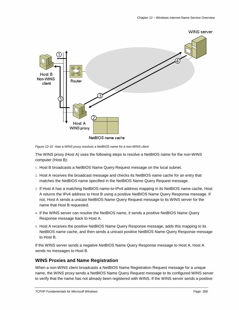
Chapter 12 – Windows Internet Name Service Overview
TCP/IP Fundamentals for Microsoft Windows Page: 358
Figure 12-10 How a WINS proxy resolves a NetBIOS name for a non-WINS client
The WINS proxy (Host A) uses the following steps to resolve a NetBIOS name for the non-WINS
computer (Host B):
1. Host B broadcasts a NetBIOS Name Query Request message on the local subnet.
2. Host A receives the broadcast message and checks its NetBIOS name cache for an entry that
matches the NetBIOS name specified in the NetBIOS Name Query Request message.
3. If Host A has a matching NetBIOS name-to-IPv4 address mapping in its NetBIOS name cache, Host
A returns the IPv4 address to Host B using a positive NetBIOS Name Query Response message. If
not, Host A sends a unicast NetBIOS Name Query Request message to its WINS server for the
name that Host B requested.
4. If the WINS server can resolve the NetBIOS name, it sends a positive NetBIOS Name Query
Response message back to Host A.
5. Host A receives the positive NetBIOS Name Query Response message, adds this mapping to its
NetBIOS name cache, and then sends a unicast positive NetBIOS Name Query Response message
to Host B.
If the WINS server sends a negative NetBIOS Name Query Response message to Host A, Host A
sends no messages to Host B.
WINS Proxies and Name Registration
When a non-WINS client broadcasts a NetBIOS Name Registration Request message for a unique
name, the WINS proxy sends a NetBIOS Name Query Request message to its configured WINS server
to verify that the name has not already been registered with WINS. If the WINS server sends a positive

Chapter 12 – Windows Internet Name Service Overview
TCP/IP Fundamentals for Microsoft Windows Page: 359
NetBIOS Name Query Response message to the WINS proxy, the proxy sends a negative NetBIOS
Name Registration Response message to the non-WINS client. If the WINS server sends a negative
NetBIOS Name Query Response message to the WINS proxy, the proxy does not respond to the non-
WINS client.
Configuration of a WINS Proxy
To enable a computer running Windows as a WINS proxy, set the
HKEY_LOCAL_MACHINE\System\CurrentControlSet\Services\NetBT\Parameters\EnableProxy registry
value to 1 (REG_DWORD), and then restart the TCP/IP NetBIOS Helper service.
Note Incorrectly editing the registry may severely damage your system. Before making changes to the
registry, you should back up any valued data on the computer.
To provide fault tolerance if a WINS proxy becomes unavailable, you should use two WINS proxies for
each subnet that contains non-WINS clients.

Chapter 12 – Windows Internet Name Service Overview
TCP/IP Fundamentals for Microsoft Windows Page: 360
Chapter Summary
The chapter includes the following pieces of key information:
WINS is the Windows implementation of a NetBIOS name server, which provides a database for
registering and querying dynamic mappings of NetBIOS names to IPv4 addresses used on your
network.
When a WINS client starts, it registers its NetBIOS names with its configured WINS server. A WINS
client renews the registration of its NetBIOS names on an ongoing basis.
WINS clients send their NetBIOS name queries to their configured WINS servers for NetBIOS name
resolution.
When a NetBIOS application on a WINS client is shut down, the WINS client releases the names
registered with its configured WINS server.
You can configure the WINS client for Windows by DHCP, through Network Connections, using the
Netsh tool, and during the establishment of a PPP connection.
The WINS Server service for
Windows Server 2008 and Windows Server 2003 supports static mappings for non-WINS clients and
WINS database replication with other WINS servers.
A pull partner is a WINS server that pulls or requests replication of updated WINS database entries
from other WINS servers (those configured to use it as a push partner) at a configured interval. Pull
partners request entries with a higher version ID than that of the last entry received from its configured
partner.
A push partner is a WINS server that pushes or notifies other WINS servers (those configured to use it
as a pull partner) of the need to replicate their database entries when a specified number of entries
have changed.
A WINS proxy is a WINS client computer configured to act on behalf of non-WINS clients. WINS
proxies help detect duplicate names and resolve NetBIOS name queries for NetBT computers.

Chapter 12 – Windows Internet Name Service Overview
TCP/IP Fundamentals for Microsoft Windows Page: 361
Chapter Glossary
DNS – See Domain Name System (DNS).
DNS client resolver cache – A RAM-based table that contains both the entries in the Hosts file and the
results of recent DNS name queries.
Domain Name System (DNS) – A hierarchical, distributed database that contains mappings of DNS
domain names to various types of data, such as IP addresses. DNS enables users to locate computers
and services by friendly names and to discover other information stored in the database.
Host name – The DNS name of a host or interface on a network. For one computer to find another, the
name of the computer to locate must either appear in the Hosts file on the computer that is looking or
be known by a DNS server. For most computers running Windows, the host name and the computer
name are the same.
Lmhosts file – A local text file that maps NetBIOS names to IP addresses for hosts that are located on
remote subnets. For computers running Windows, this file is stored in the
systemroot\System32\Drivers\Etc folder.
NBNS – See NetBIOS name server (NBNS).
NetBIOS name - A 16-byte name of a process using NetBIOS.
NetBIOS name cache – A dynamically maintained table on a NetBIOS-enabled host. The NetBIOS
name cache stores recently resolved NetBIOS names and their associated IPv4 addresses.
NetBIOS name resolution – The process of resolving a NetBIOS name to an IPv4 address.
NetBIOS name server (NBNS) – A server that stores mappings of NetBIOS names to IPv4 addresses
and that resolves NetBIOS names for NetBIOS-enabled hosts. The WINS Server service is the
Microsoft implementation of a NetBIOS name server.
NetBIOS node type – A designation of the specific way that NetBIOS nodes resolve NetBIOS names.
Network Basic Input/Output System (NetBIOS) – A standard Session layer API for user applications
and a protocol for session management and data transport.
pull partner – A WINS component that requests replication of updated WINS database entries from its
push partner.
push partner – A WINS component that notifies its pull partner when updated WINS database entries
are available for replication.
static mapping – A manually created entry in the database of a WINS server so that WINS clients can
resolve the NetBIOS names of non-WINS clients.
Time-to-Live – The amount of time that a NetBIOS name is stored on a WINS server. The TTL is
configured on the WINS server.
TTL – See Time-to-Live.
Windows Internet Name Service (WINS) – The Microsoft implementation of a NetBIOS name server.
WINS – See Windows Internet Name Service (WINS).
Chapter 12 – Windows Internet Name Service Overview
TCP/IP Fundamentals for Microsoft Windows Page: 362
WINS client – A component of the TCP/IP protocol for Windows that supports NetBIOS name
operations using a WINS server.
WINS proxy – A WINS client computer configured to act on behalf of non-WINS clients. WINS proxies
help detect duplicate NetBIOS names and resolve NetBIOS name queries for NetBT computers.
WINS server – A computer running the WINS Server service.

Chapter 13 – Internet Protocol Security and Packet Filtering
TCP/IP Fundamentals for Microsoft Windows Page: 363
Chapter 13 – Internet Protocol Security and Packet Filtering
Abstract
This chapter describes the support for Internet Protocol security (IPsec) and IP packet filtering in Microsoft Windows
operating systems. IPsec can provide cryptographic protection for IP packet payloads. Packet filtering can specify which
types of packets are received or dropped. A network administrator must understand IPsec and packet filtering and its
effect on IP network traffic to configure network security and troubleshoot connectivity problems.

Chapter 13 – Internet Protocol Security and Packet Filtering
TCP/IP Fundamentals for Microsoft Windows Page: 364
Chapter Objectives
After completing this chapter, you will be able to:
Describe the roles that IPsec and IP packet filtering play in helping to protect network nodes.
Define IPsec and its uses to block, permit, or help protect IP traffic.
Define packet filtering and its uses to block or permit IP traffic.
List and describe the security properties of IPsec-protected traffic.
Describe the functions of the Authentication Header, Encapsulating Security Payload, and Internet Key
Exchange IPsec protocols.
Distinguish between transport mode and tunnel mode.
Describe the purposes of main mode and quick mode IPsec negotiations.
Define an IPsec policy in terms of its general settings and rules.
List and describe the configuration elements of an IPsec rule.
Describe Windows Firewall and how you can use it to help protect against malicious users and
programs.
Describe Internet Connection Firewall.
Describe TCP/IP filtering and its configuration.
Describe what Basic Firewall does and how Routing and Remote Access can filter IPv4 packets.
Describe how the basic IPv6 firewall, the IPv6 Internet Connection Firewall, and Windows Firewall filter
IPv6 packets.
Chapter 13 – Internet Protocol Security and Packet Filtering
TCP/IP Fundamentals for Microsoft Windows Page: 365
IPsec and Packet Filtering Overview
The Internet was originally designed for wide-open communications between connected computers.
However, today's Internet is a hostile networking environment. Computers on the Internet must protect
themselves from malicious users and programs that attempt to disable, control, or improperly access
the resources of the computer. Private intranets can also contain malicious users and programs. On
either the Internet or a private intranet, sensitive data should be cryptographically protected before
being sent to its destination. In some cases, laws require you to cryptographically protect data sent over
the network.
To help protect traffic or prevent unwanted traffic, Windows Vista, Windows XP, Windows Server 2008,
and Windows Server 2003 include the following technologies:
IPsec A framework of open standards for helping ensure private, protected communications over
Internet Protocol (IP) networks through the use of cryptographic security services. The Windows
implementations of IPsec are based on standards developed by the IPsec working group of the Internet
Engineering Task Force (IETF).
Packet filtering The ability to configure interfaces to accept or discard incoming traffic based on a
variety of criteria such as Transmission Control Protocol (TCP) and User Datagram Protocol (UDP)
ports, source and destination IP addresses, and whether the incoming traffic was sent because the
receiving computer requested it.
This chapter describes these two technologies and how Windows Vista, Windows XP, Windows Server
2008, and Windows Server 2003 support them.

Chapter 13 – Internet Protocol Security and Packet Filtering
TCP/IP Fundamentals for Microsoft Windows Page: 366
IPsec
The original standards for the TCP/IP protocol suite were not designed to protect IP packets. By default,
IP packets are easy to interpret, modify, replay, and forge. Without protection for IP packet payloads,
both public and private networks are susceptible to unauthorized monitoring and access. Although
internal attacks might result from minimal or nonexistent intranet security, risks from outside a private
network stem from connections to both the Internet and extranets. Requiring passwords to access
network resources, such as permissions on a shared folder, does not protect data transmitted across a
network.
IPsec is the long-term direction for standards-based, protected, IP-based networking. It provides a key
line of defense against private network and Internet attacks, balancing ease of deployment with strong
security. IPsec has two goals:
1. To protect IP packets
2. To defend against network attacks
Both of these goals are met through the use of cryptography-based protection services, security
protocols, and dynamic key management. This foundation provides the strength and flexibility required
to help protect communications between private network computers, domains, sites, remote sites,
extranets, and dial-up clients. You can further use IPsec to block receipt or transmission of specific
traffic types.
IPsec is based on an end-to-end security model. The only computers that must be aware of IPsec are
the sending and receiving computers. Each handles security at its respective end and assumes that the
medium over which the communication takes place is not protected. Computers that only route data
from source to destination are not required to support IPsec, but they are required to forward IPsec
traffic.
Security Properties of IPsec-protected Communications
IPsec provides the following security properties to help protect communications:
Data integrity Helps protect data from unauthorized modification in transit. Data integrity helps ensure
that the data received is exactly the same as the data sent. Hash functions authenticate each packet
with a cryptographic checksum using a shared, secret key. Only the sender and receiver have the key
that is used to calculate the checksum. If the packet contents have changed, the cryptographic
checksum verification fails and the receiver discards the packet.
Data origin authentication Helps verify that the data could have been sent only from a computer that
has the shared, secret key. The sender includes a message authentication code with a calculation that
includes the shared, secret key. The receiver performs the same calculation and discards the message
if the receiver’s calculation does not match the message authentication code that is included in the
message. The message authentication code is the same as the cryptographic checksum that is used
for data integrity.
Confidentiality (encryption) Helps ensure that the data is disclosed only to intended recipients.
Confidentiality is achieved by encrypting the data before transmission. Encryption ensures that the data
cannot be interpreted during its transit across the network, even if a malicious user intercepts and

Chapter 13 – Internet Protocol Security and Packet Filtering
TCP/IP Fundamentals for Microsoft Windows Page: 367
captures the packet. Only the communicating computers with the shared, secret key can easily decrypt
the packet contents and determine the original data.
Anti-replay Helps ensure the uniqueness of each IP packet by placing a sequence number on each
packet. Anti-replay is also called replay prevention. Anti-replay helps ensure that a malicious user
cannot capture data and reuse or replay it, possibly months later, to establish a session or to gain
access to information or other resources.
IPsec Protocols
IPsec provides its security services by wrapping the payload of an IP packet with an additional header
or trailer that contains the information to provide data origin authentication, data integrity, data
confidentiality, and replay protection. IPsec headers consist of the following:
Authentication header (AH)
Provides data authentication, data integrity, and replay protection for an IP packet.
Encapsulating Security Payload (ESP) header and trailer
Provides data authentication, data integrity, replay protection, and data confidentiality for an IP
packet payload.
The result of applying the AH or the ESP header and trailer to an IP packet transforms the packet into a
protected packet.
To negotiate the set of security parameters to help protect the traffic, such as whether to use AH or
ESP and what types of encryption and authentication algorithms to use, IPsec peers use the Internet
Key Exchange (IKE) protocol.
IPsec Modes
IPsec supports two modes—transport mode and tunnel mode—that describe how the original IP packet
is transformed into a protected packet.
Transport Mode
Transport mode protects an IP payload through an AH or an ESP header. Typical IP payloads are TCP
segments (which contain a TCP header and TCP segment data), UDP messages (which contain a UDP
header and UDP message data), and Internet Control Message Protocol (ICMP) messages (which
contain an ICMP header and ICMP message data).
AH in transport mode provides data origin authentication, data integrity, and anti-replay for the entire
packet (both the IP header and the data payload carried in the packet, except for fields in the IP header
that must change in transit). This type of protection does not provide confidentiality, which means that it
does not encrypt the data. The data can be read but not easily modified or impersonated. AH uses
keyed hash algorithms for packet integrity.
For example, Computer A sends data to Computer B. The IP header, the AH header, and the IP
payload are protected with data integrity and data origin authentication. Computer B can determine that
Computer A really sent the packet and that the packet was not modified in transit.
AH is identified in the IP header with an IP protocol ID of 51. You can use AH alone or combine it with
ESP.

Chapter 13 – Internet Protocol Security and Packet Filtering
TCP/IP Fundamentals for Microsoft Windows Page: 368
The AH header contains a Security Parameters Index (SPI) field that IPsec uses in combination with
the destination address and the security protocol (AH or ESP) to identify the correct security association
(SA) for the communication. IPsec at the receiver uses the SPI value to determine with which SA the
packet is identified. To prevent replay attacks, the AH header also contains a Sequence Number field.
An Authentication Data field in the AH header contains the integrity check value (ICV), also known as
the message authentication code, which is used to verify both data integrity and data origin
authentication. The receiver calculates the ICV value and checks it against this value (which is
calculated by the sender) to verify integrity. The ICV is calculated over the IP header, the AH header,
and the IP payload.
AH authenticates the entire packet for data integrity and data origin authentication, with the exception of
some fields in the IP header that might change in transit (for example, the Time to Live and Checksum
fields). Figure 13-1 shows the original IP packet and how it is protected with AH in transport mode.
Figure 13-1 A packet protected with AH in transport mode
ESP in transport mode provides confidentiality (in addition to data origin authentication, data integrity,
and anti-replay) for an IP packet payload. ESP in transport mode does not authenticate the entire
packet. Only the IP payload (not the IP header) is protected. You can use ESP alone or combine it with
AH. For example, Computer A sends data to Computer B. The IP payload is encrypted and
authenticated. Upon receipt, IPsec verifies data integrity and data origin authentication and then
decrypts the payload.
ESP is identified in the IP header with the IP protocol ID of 50 and consists of an ESP header that is
placed before the IP payload, and an ESP and authentication data trailer that is placed after the IP
payload.
Like the AH header, the ESP header contains SPI and Sequence Number fields. The Authentication
Data field in the ESP trailer is used for message authentication and integrity for the ESP header, the
payload data, and the ESP trailer.
Figure 13-2 shows the original IP packet and how it is protected with ESP. The authenticated portion of
the packet indicates where the packet has been protected for data integrity and data origin
authentication. The encrypted portion of the packet indicates what information is confidential.

Chapter 13 – Internet Protocol Security and Packet Filtering
TCP/IP Fundamentals for Microsoft Windows Page: 369
Figure 13-2 A packet protected with ESP in transport mode
The IP header is not authenticated and is not protected from modification. To provide data integrity and
data origin authentication for the IP header, use ESP and AH.
Tunnel Mode
Tunnel mode helps protect an entire IP packet by treating it as an AH or ESP payload. With tunnel
mode, an IP packet is encapsulated with an AH or an ESP header and an additional IP header. The IP
addresses of the outer IP header are the tunnel endpoints, and the IP addresses of the encapsulated IP
header are the original source and final destination addresses.
As Figure 13-3 shows, AH tunnel mode encapsulates an IP packet with an AH and an IP header and
authenticates the entire packet for data integrity and data origin authentication.
Figure 13-3 A packet protected with AH in tunnel mode
As Figure 13-4 shows, ESP tunnel mode encapsulates an IP packet with both an ESP and IP header
and an ESP authentication trailer.

Chapter 13 – Internet Protocol Security and Packet Filtering
TCP/IP Fundamentals for Microsoft Windows Page: 370
Figure 13-4 A packet protected with ESP in tunnel mode
Because a new header for tunneling is added to the packet, everything that comes after the ESP
header is authenticated (except for the ESP Authentication Data field) because it is now encapsulated
in the tunneled packet. The original header is placed after the ESP header. The entire packet is
appended with an ESP trailer before encryption occurs. Everything that follows the ESP header is
encrypted, including the original header that is now part of the data portion of the packet but not
including the ESP authentication data field.
The entire ESP payload is then encapsulated within a new IP header, which is not encrypted. The
information in the new IP header is used only to route the packet to the tunnel endpoint.
If the packet is being sent across a public network, the packet is routed to the IP address of the tunnel
server for the receiving intranet. In most cases, the packet is destined for an intranet computer. The
tunnel server decrypts the packet, discards the ESP header, and uses the original IP header to route
the packet to the destination intranet computer.
In tunnel mode, you can combine ESP with AH, providing both confidentiality for the tunneled IP packet
and data integrity and data origin authentication for the entire packet.
Negotiation Phases
Before two computers can exchange protected data, they must establish a contract. In this contract,
called a security association (SA), both computers agree on how to protect information. An SA is the
combination of a negotiated encryption key, security protocol, and SPI, which together define the
security used to protect the communication from sender to receiver. The SPI is a unique, identifying
value in the SA that is used to distinguish among multiple SAs that exist at the receiving computer.
For example, multiple SAs might exist if a computer using IPsec protection is communicating with
multiple computers at the same time. This situation occurs frequently when the computer is a file server
or a remote access server that serves multiple clients. In these situations, the receiving computer uses
the SPI to determine which SA the computer should use to process the incoming packets.
To build this contract between the two computers, the IETF has defined IKE as the standard method of
SA and key determination. IKE does the following:
Centralizes SA management, reducing connection time.

Chapter 13 – Internet Protocol Security and Packet Filtering
TCP/IP Fundamentals for Microsoft Windows Page: 371
Generates and manages shared, secret keys that help protect the information.
This process not only helps protect communication between computers, it also helps protect remote
computers that request protected access to a corporate network. In addition, this process works
whenever a security gateway performs the negotiation for the final destination computer.
Phase I or Main Mode Negotiation
To help ensure successful and protected communication, IKE performs a two-phase operation. IKE
helps ensure confidentiality and authentication during each phase by using encryption and
authentication algorithms that the two computers agree on during security negotiations. With the duties
split between two phases, keys can be created rapidly.
During the first phase, the two computers establish a protected, authenticated channel. This phase is
called the phase I SA or main mode SA. IKE automatically protects the identities of the two computers
during this exchange.
A main mode negotiation consists of the following steps:
1. Policy negotiation
The following four mandatory parameters are negotiated as part of the main mode SA:
The encryption algorithm
The hash algorithm
The authentication method
The Diffie-Hellman (DH) group to be used for the base keying material
Different versions of Windows support different sets of encryption algorithms, hash algorithms,
authentication methods, and DH groups. For more information, see Windows Help and Support.
2. DH exchange
At no time do the two computers exchange actual keys. The computers exchange only the base
information that the DH key determination algorithm requires to generate the shared, secret key.
After this exchange, the IKE service on each computer generates the master key that the computers
use for subsequent communications.
3. Authentication
The computers attempt to authenticate the DH key exchange. A DH key exchange without
authentication is vulnerable to a man-in-the-middle attack. A man-in-the-middle attack occurs when a
computer masquerades as the endpoint between two communicating peers. Without successful
authentication, communication cannot proceed. The communicating peers use the master key, in
conjunction with the negotiation algorithms and methods, to authenticate identities. The
communicating peers hash and encrypt the entire identity payload (including the identity type, port,
and protocol) using the keys generated from the DH exchange in the second step. The identity
payload, regardless of which authentication method is used, is protected from both modification and
interpretation.

Chapter 13 – Internet Protocol Security and Packet Filtering
TCP/IP Fundamentals for Microsoft Windows Page: 372
The initiator offers a potential SA to the receiver. The responder cannot modify the offer. Should the
offer be modified, the initiator rejects the responder's message. The responder sends either a reply
accepting the offer or a reply with alternatives.
Phase II or Quick Mode Negotiation
In this phase, the IPsec peers negotiate the SAs to protect the actual data sent between them. A quick
mode negotiation consists of the following steps:
1. Policy negotiation occurs.
The IPsec peers exchange the following requirements to protect the data transfer:
The IPsec protocol (AH or ESP)
The hash algorithm
The algorithm for encryption, if requested
The computers reach a common agreement and establish two SAs. One SA is for inbound
communication, and the other is for outbound communication.
2. Session key material is refreshed or exchanged.
IKE refreshes the keying material, and new shared keys are generated for data integrity, data origin
authentication, and encryption (if negotiated). If rekeying is required, either a second DH exchange
(as described in main mode negotiation) occurs, or a refresh of the original DH key is used.
The main mode SA helps protect the quick mode negotiation of security settings and keying material
(for the purpose of securing data). The first phase helped protect the computers’ identities, and the
second phase helps protect the keying material by refreshing it before sending data. IKE can
accommodate a key exchange payload for an additional DH exchange if a rekey is necessary.
Otherwise, IKE refreshes the keying material from the DH exchange completed in main mode.
Windows Vista and Windows Server 2008 also support extended mode negotiation with Authenticated
IP (AuthIP), during which IPsec peers can perform a second round of authentication. For more
information, see The Authenticated Internet Protocol.
There are two ways to configure IPsec settings through the Windows graphical user interface:
Connection security rules through the Windows Firewall with Advanced Security snap-in (for Windows
Vista and Windows Server 2008)
IPsec policy settings through the IPsec Policy Management snap-in
Connection Security Rules
Connection security rules in the Windows Firewall with Advanced Security snap-in specify what traffic to
protect and how to protect it, and provide a highly simplified way to configure IPsec settings.
To configure a connection security rule, do the following:
1. From the console tree of the Windows Firewall with Advanced Security snap-in, right-click
Connection Security Rules, and then click New Rule.
2. Follow the pages of the New Connection Security Rule wizard to configure a rule for a common traffic
protection scenario or a custom rule.

Chapter 13 – Internet Protocol Security and Packet Filtering
TCP/IP Fundamentals for Microsoft Windows Page: 373
IPsec Policy Settings
An IPsec policy configured through the IPsec Policy Management snap-in consists of the following:
General IPsec policy settings
Settings that apply regardless of which rules are configured. These settings determine the name of
the policy, its description for administrative purposes, main mode key exchange settings, and main
mode key exchange methods.
Rules
One or more IPsec rules that determine which types of traffic IPsec must examine, how traffic is
treated (permitted, blocked, or protected), how to authenticate an IPsec peer, and other settings.
IPsec policies can be applied to local computers, domains, sites, or organizational units on any Group
Policy object in Active Directory. Your IPsec policies should be based on your organization's written
guidelines for protected traffic. Policies can store multiple rules, so one policy can govern multiple types
of traffic.
IPsec policies can be stored in two locations:
Active Directory
IPsec policies that are stored in Active Directory are part of Computer Configuration Group Policy
settings and are downloaded to an Active Directory domain member when it joins the domain and
on an ongoing basis. The Active Directory-based policy settings are locally cached. If the computer
has downloaded such policy settings but is not connected to a network that contains a trusted
Windows Server 2008 or Windows Server 2003 domain controller, IPsec uses the locally cached
Active Directory IPsec policy settings.
Local
Local IPsec policies are defined in the local computer's Computer Configuration Group Policy for
stand-alone computers and computers that are not always members of a trusted Windows
Server 2008 or Windows Server 2003 domain.
Windows Vista, Windows XP, Windows Server 2008, and Windows Server 2003 include default policies
that you can use as examples for your own custom policies.
General IPsec Policy Settings
You configure the general settings for an IPsec policy in the Group Policy snap-in (under Computer
Configuration-Windows Settings-Security Settings-IP Security Policies) by right-clicking an IPsec policy,
clicking Properties, clicking the General tab, and configuring the following:
Name The name for the policy.
Description Optional text that describes the purpose of the IPsec policy. You should type a description
to summarize the settings and rules for the policy.
Policy change poll interval The number of minutes between consecutive polls for changes in IPsec
policies that are based on Active Directory. This polling does not detect changes in domain or
organizational unit membership or the assigning or unassigning of a new policy. These events are

Chapter 13 – Internet Protocol Security and Packet Filtering
TCP/IP Fundamentals for Microsoft Windows Page: 374
detected when the Winlogon service polls for changes in Group Policy, which occurs by default every
90 minutes.
Figure 13-5 shows the General tab for the default Server (Request Security) IPsec policy.
Figure 13-5 The General tab of the properties of an IPsec policy
By clicking Settings, you can configure the following:
Key exchange settings
The way in which new keys are derived and how often they are renewed.
Key exchange methods
The ways in which identities are protected during the key exchange.
The default key exchange settings and methods are configured to work for most IPsec deployments.
Unless you have special security requirements, you should not need to change these default settings.
Figure 13-6 shows the Key Exchange Settings dialog box for the default Server (Request Security)
IPsec policy.
Figure 13-6 The Key Exchange Settings dialog box

Chapter 13 – Internet Protocol Security and Packet Filtering
TCP/IP Fundamentals for Microsoft Windows Page: 375
Rules
An IPsec policy consists of one or more rules that determine IPsec behavior. You configure IPsec rules
on the Rules tab in the properties of an IPsec policy. For each IPsec rule, you can configure the
following items:
Filter list
You specify a single filter list that contains one or more predefined packet filters that describe the
types of traffic to which the configured filter action for this rule is applied.
Filter action
You specify a single filter action that includes the type of action required (permit, block, or secure)
for packets that match the filter list. For the secure filter action, the negotiation data contains one or
more security methods that are used (in order of preference) during IKE negotiations and other
IPsec settings. Each security method determines the security protocol (such as AH or ESP), the
specific cryptographic algorithms, and the settings for regenerating session keys used.
Authentication methods
You configure one or more authentication methods (in order of preference) for authenticating IPsec
peers during main mode negotiations. You can specify the Kerberos V5 protocol, use of a certificate
issued from a specified certification authority, or a preshared key.
Tunnel endpoint
You can specify whether the traffic is using tunnel mode and, if so, the IP address of the tunnel
endpoint. For outbound traffic, the tunnel endpoint is the IP address of the IPsec tunnel peer. For
inbound traffic, the tunnel endpoint is a local IP address.
Connection type
You can specify whether the rule applies to local area network (LAN) connections, dial-up
connections, or both.
Figure 13-7 shows the properties of a rule for the default Server (Request Security) IPsec policy.

Chapter 13 – Internet Protocol Security and Packet Filtering
TCP/IP Fundamentals for Microsoft Windows Page: 376
Figure 13-7 Properties of an IPsec rule
The rules for a policy appear in reverse alphabetical order based on the name of the filter list selected
for each rule. You cannot specify an order in which to apply the rules in a policy. The Windows
implementation of IPsec automatically derives a set of IPsec filters that specify IP traffic and the action
that IPsec has been configured to take for the traffic. IPsec filters are ordered based on the most
specific to the least specific IP traffic. For example, an IPsec filter that specifies individual IP addresses
and TCP ports is ordered before an IPsec filter that specifies all addresses on a subnet.
Default Response Rule
The default response rule, which can be used for all policies, has the IP filter list of <Dynamic> and the
filter action of Default Response when the list of rules is viewed with IP Security Policies. You cannot
delete the default response rule, but you can deactivate it. It is activated for all of the default policies,
and you can enable it when you create IPsec policies.
The default response rule ensures that the computer responds to requests for protected
communication. If an active policy does not have a rule defined for a computer that is requesting
protected communication, the default response rule is applied, and protection is negotiated. For
example, the default response rule is used when Computer A communicates with protection with
Computer B and Computer B does not have an inbound filter defined for Computer A.
You can configure authentication methods and the connection type for the default response rule. The
filter list of <Dynamic> indicates that the filter list is not configured, but filters are created automatically
when IKE negotiation packets are received. The filter action of Default Response indicates that you
cannot configure the action of the filter (permit, block, or negotiate security). However, you can
configure:
The security methods and their preference order. To configure these settings, obtain properties on the
IPsec policy, click the Rules tab, click the default response rule, click Edit, and then click the Security
Methods tab.
The authentication methods and their preference order. To configure these settings, click the default
response rule, click Edit, and click the Authentication Methods tab.
Filter List
An IP filter list triggers a filter action based on a match with the source, destination, and type of IP
traffic. This type of IP packet filtering enables a network administrator to precisely define what IP traffic
to allow, block, or protect. Each IP filter list contains one or more filters, which define IP addresses and
traffic types. You can use one IP filter list for multiple types of IP traffic.
For protected packets, IPsec requires you to configure both an inbound and outbound filter between the
computers specified in the filter list. Inbound filters apply to incoming traffic, enabling the receiving
computer to respond to requests for protected communication or to match traffic against the IP filter list.
Outbound filters apply to traffic leaving a computer toward a destination, triggering a security
negotiation that takes place before traffic is sent. For example, if Computer A wants to exchange
protected data with Computer B:
The active IPsec policy on Computer A must have a filter that specifies any outbound packets to
Computer B.

Chapter 13 – Internet Protocol Security and Packet Filtering
TCP/IP Fundamentals for Microsoft Windows Page: 377
The active IPsec policy on Computer A must have a filter that specifies any inbound packets from
Computer B.
Each peer must also have the reverse filter. For example:
The active IPsec policy on Computer B must have a filter that specifies any inbound packets from
Computer A.
The active IPsec policy on Computer B must have a filter that specifies any outbound packets to
Computer A.
Filter Settings
Each filter defines a particular subset of inbound or outbound network traffic. You must have a filter to
cover any traffic to which the associated rule applies. A filter can contain the following settings:
The source and destination address of the IP packet. You can configure any IP address assigned to the
IPsec peer, a single IP address, IP addresses by DNS name, or address ranges to specify IP subnets.
The protocol over which the packet is being transferred. This setting by default covers all protocols in
the TCP/IP protocol suite. However, you can configure the filter for an individual protocol to meet
special requirements, including custom protocols.
For TCP and UDP, the source and destination port of the protocol. By default, all TCP and UDP ports
are covered, but you can configure the filter to apply to only a specific TCP or UDP port.
Figure 13-8 shows the All ICMP Traffic filter list for the default Server (Request Security) IPsec
policy.
Figure 13-8 An example IP filter list
Filter Action
A filter action defines how the Windows implementation of IPsec must treat IP traffic. Figure 13-9 shows
the Require Security filter action for the default Server (Request Security) IPsec policy.

Chapter 13 – Internet Protocol Security and Packet Filtering
TCP/IP Fundamentals for Microsoft Windows Page: 378
Figure 13-9 An IPsec filter action
You can configure a filter action to:
Permit traffic (the Permit setting)
The Windows implementation of IPsec forwards the traffic without modification or protection. This
setting is appropriate for traffic from specific computers that cannot support IPsec.
Block traffic (the Block setting)
IPsec silently discards this traffic.
Negotiate IPsec (the Negotiate Security setting)
IPsec requires the sender and receiver to negotiate SAs and to send and receive IPsec-protected
traffic. After you choose to negotiate IPsec, you can also do the following:
Specify security methods and their order
Allow initial incoming unprotected traffic (the Accept unsecured communication, but always
respond using IPsec setting)
If you configure this setting, IPsec allows an incoming packet that matches the configured filter
list to be unprotected by IPsec. However, the outgoing response to the incoming packet must
be protected. This behavior is also known as inbound pass-through.
This setting is useful when you are using the default response rule for clients. For example, a
group of servers are configured with a rule that protects communications with any IP address,
accepts communication that is not protected, and responds with only protected
communications. To ensure that the clients will respond to the server request to negotiate
security, you must enable the default response rule on client computers.
Enable communication with computers on which IPsec is not enabled (the Allow unsecured
communication with non-IPsec-aware computer setting)
If you configure this setting, IPsec falls back to unprotected communication, if necessary. This
behavior is known as fallback to clear.

Chapter 13 – Internet Protocol Security and Packet Filtering
TCP/IP Fundamentals for Microsoft Windows Page: 379
You can use this setting to allow communication with computers that cannot initiate IPsec, such
as computers running Microsoft operating systems older than Windows 2000.
Generate session keys from new keying material (the Session key perfect forward secrecy
(PFS) setting)
This setting determines whether a new session key can be derived from existing material for
keying a master key determined from a main mode negotiation. By enabling session key PFS,
you ensure that master key keying material cannot be used to derive more than one session
key. When session key PFS is enabled, a new Diffie-Hellman key exchange is performed to
generate new master key keying material before the new session key is created. Session key
PFS does not require main mode reauthentication and uses fewer resources than master key
PFS.
IPsec Security Methods
Each security method defines the security requirements of any communications to which the associated
rule applies. By creating multiple security methods, you increase the chance that a common method
can be found between two computers. The IKE component reads the list of security methods in
descending order and sends a list of allowed security methods to the other peer. The first method in
common is selected. Typically, the methods with the most cryptographic strength are at the top of the
list and the methods with the least cryptographic strength are at the bottom of the list.
The following security methods are predefined:
Encryption and integrity Uses ESP to provide data confidentiality (encryption), data integrity and data
origin authentication, and default key lifetimes (100MB, 1 hour). If you require both data and addressing
(IP header) protection, you can create a custom security method. If you do not require encryption, you
can use Integrity only.
Integrity only Uses ESP to provide data integrity and authentication and default key lifetimes (100MB,
1 hour). In this configuration, ESP does not provide data confidentiality (encryption). This method is
appropriate when your security plan calls for standard levels of security.
Figure 13-10 shows the New Security Method tab, which appears when you add a security method to
a filter action.
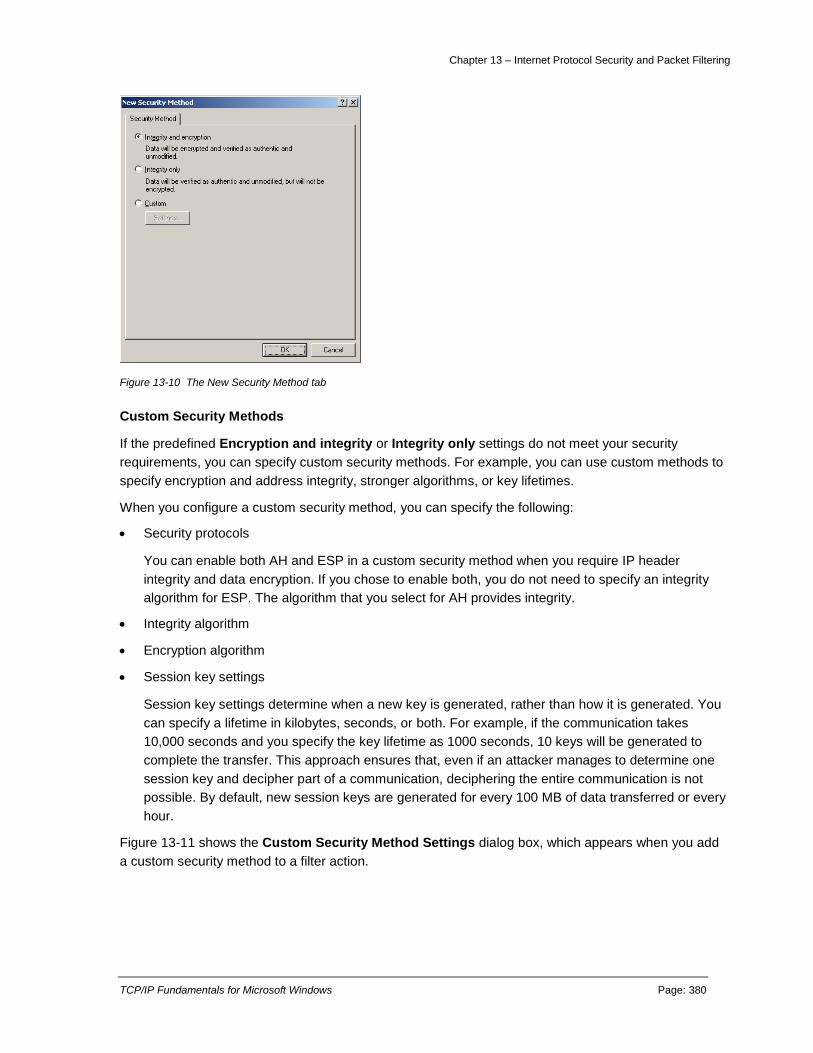
Chapter 13 – Internet Protocol Security and Packet Filtering
TCP/IP Fundamentals for Microsoft Windows Page: 380
Figure 13-10 The New Security Method tab
Custom Security Methods
If the predefined Encryption and integrity or Integrity only settings do not meet your security
requirements, you can specify custom security methods. For example, you can use custom methods to
specify encryption and address integrity, stronger algorithms, or key lifetimes.
When you configure a custom security method, you can specify the following:
Security protocols
You can enable both AH and ESP in a custom security method when you require IP header
integrity and data encryption. If you chose to enable both, you do not need to specify an integrity
algorithm for ESP. The algorithm that you select for AH provides integrity.
Integrity algorithm
Encryption algorithm
Session key settings
Session key settings determine when a new key is generated, rather than how it is generated. You
can specify a lifetime in kilobytes, seconds, or both. For example, if the communication takes
10,000 seconds and you specify the key lifetime as 1000 seconds, 10 keys will be generated to
complete the transfer. This approach ensures that, even if an attacker manages to determine one
session key and decipher part of a communication, deciphering the entire communication is not
possible. By default, new session keys are generated for every 100 MB of data transferred or every
hour.
Figure 13-11 shows the Custom Security Method Settings dialog box, which appears when you add
a custom security method to a filter action.

Chapter 13 – Internet Protocol Security and Packet Filtering
TCP/IP Fundamentals for Microsoft Windows Page: 381
Figure 13-11 The Custom Security Methods dialog box
Authentication
Each IPsec rule defines a list of authentication methods. Each authentication method defines the
requirements for how identities are verified in protected communications to which the associated rule
applies. The two peers must have at least one authentication method in common or communication will
fail. By creating multiple authentication methods, you increase the chance that the two computers can
find a common method.
Only one authentication method can be used between a pair of computers, regardless of how many you
configure. If you have multiple rules that apply to the same pair of computers, you must configure the
authentication methods lists in those rules to enable the pair to use the same method. For example,
authentication will fail if a rule between a pair of computers specifies only Kerberos for authentication
and filters only TCP data and another rule specifies only certificates for authentication and filters only
UDP data.
IPsec supports the following authentication methods:
Kerberos V5 The Kerberos V5 security protocol is the default authentication method for clients that are
running the Kerberos V5 protocol and that are members of the same or trusted Active Directory
domains.
Kerberos V5 authentication is not supported on computers running Windows XP Home Edition or
computers running any other Windows 2000, Windows XP, or Windows Server 2003 operating
system that are not members of an Active Directory domain.
Public key certificate You should use a public key certificate in situations that include Internet access,
access to corporate resources from remote locations, communications with external business partners,
or computers that do not run the Kerberos V5 security protocol. This method requires you to obtain
certificates from at least one trusted certification authority (CA). Computers running Windows
Server 2003, Windows XP, or Windows 2000 support X.509 Version 3 certificates, including certificates
generated by commercial CAs.
Preshared key This method involves a shared, secret key similar to a password. It is simple to use
and does not require the client to run the Kerberos V5 protocol or have a public key certificate. Both
parties must manually configure IPsec to use this preshared key. Preshared key is a simple method for

Chapter 13 – Internet Protocol Security and Packet Filtering
TCP/IP Fundamentals for Microsoft Windows Page: 382
authenticating computers that are not running Windows Server 2003, Windows XP, or Windows 2000;
stand-alone computers; or any computers that are not using the Kerberos V5 protocol. This key is for
peer authentication protection only and is not used to protect the data sent between IPsec peers.
Tunnel Endpoint
IPsec tunnels help protect entire IP packets. You configure the tunnel to help protect traffic between
either two IP addresses or two IP subnets. If you configure the tunnel between two computers instead
of two routers (also known as gateways), the IP address outside the AH or ESP payload is the same as
the IP address inside the AH or ESP payload.
IPsec can perform layer 3 tunneling for scenarios in which Layer Two Tunneling Protocol (L2TP) cannot
be used. You do not need to configure a tunnel if you are using L2TP for remote communications
because the client and server virtual private networking (VPN) components of Windows automatically
create the appropriate rules to protect L2TP traffic.
To create a layer 3 tunnel using IPsec, use IP Security Policies or Group Policy to configure and enable
the following two rules for the appropriate policy:
1. A rule for outbound traffic through the tunnel.
You configure the rule for outbound traffic with both a filter list, which describes the traffic to be sent
across the tunnel, and a tunnel endpoint, which is an IP address assigned to the IPsec tunnel peer
(the computer or router on the other side of the tunnel).
2. A rule for inbound traffic through the tunnel.
You configure the rule for inbound traffic with both a filter list, which describes the traffic to be
received across the tunnel, and a tunnel endpoint, which is a local IP address (the computer or router
on this side of the tunnel).
For each rule, you must also specify filter actions, authentication methods, and other settings.
Connection Type
For each IPsec rule, you must define to which connection types on your computer the rule will apply.
The connection types include all connections in Network Connections on the computer for which you
are configuring IPsec policy.
Each rule has one connection type setting:
All Network Connections The rule applies to communications sent through any network connection
that you have configured on the computer.
Local Area Network (LAN) The rule applies only to communications sent through LAN connections
that you have configured on the computer.
Remote Access The rule applies only to communications sent through any remote access or dial-up
connections that you have configured on the computer.

Chapter 13 – Internet Protocol Security and Packet Filtering
TCP/IP Fundamentals for Microsoft Windows Page: 383
IPsec for IPv6 Traffic
Windows Vista and Windows Server 2008 include the same support for IPv6 traffic as IPv4 traffic. You
can use either the Windows Firewall with Advanced Security or IP Security Policy Management snap-
ins to configure IPsec settings to protect IPv6 traffic.
However, the IPv6 protocol for Windows Server 2003 and Windows XP has the following limitations:
Supports AH in transport or tunnel mode using MD5 or SHA1 and ESP in transport or tunnel mode
using the NULL ESP header and MD5 or SHA1. IPv6 does not support ESP data encryption.
Is separate from—and not interoperable with—IPsec for the IPv4 protocol. IPsec policies that are
configured with IP Security Policies or Group Policy have no effect on IPv6 traffic.
Does not support the use of IKE to negotiate SAs. You must use the Ipsec6.exe tool to manually
configure IPsec policies, SAs, and encryption keys. For more information, see Help and Support in
Windows XP or Windows Server 2003.

Chapter 13 – Internet Protocol Security and Packet Filtering
TCP/IP Fundamentals for Microsoft Windows Page: 384
Packet Filtering
In addition to using IPsec filter actions to perform packet filtering, computers running Windows Vista,
Windows XP, Windows Server 2008, or Windows Server 2003 support Windows Firewall. Computers
running Windows Server 2003 or Windows XP also support the Internet Connection Firewall and
TCP/IP filtering.
On computers running Windows Server 2008 or Windows Server 2003 with Routing and Remote
Access, you can also use IP packet filtering. On computers running Windows Server 2003 with no
service packs installed and Routing and Remote Access, you can also use the Basic Firewall
component.
Windows Firewall
A firewall is a protective boundary between a computer or network and the outside world. Windows
Firewall is a stateful host firewall for IPv4 and IPv6 traffic in Windows Vista, Windows Server 2008,
Windows XP with Service Pack 2 (SP2) and later, and Windows Server 2003 with Service Pack 1 (SP1)
and later. This feature allows incoming traffic only if it is either solicited (sent in response to a request of
the computer) or excepted (unsolicited traffic that has been specified as allowable). Windows Firewall
provides a level of protection from malicious users and programs that use unsolicited traffic to attack
computers. Windows Firewall in Windows Vista and Windows Server 2008 can also block outgoing
traffic. Windows Firewall in Windows XP and Windows Server 2003 does not block outgoing traffic, with
the exception of some Internet Control Message Protocol (ICMP) messages.
Windows Firewall is designed for use on all network connections, including those that are accessible
from the Internet, connected to small office/home office networks, or connected to private organization
networks. An organization network's firewall, proxy, and other security systems provide some level of
protection from the Internet to intranet network computers. However, the absence of host firewalls such
as Windows Firewall on intranet connections leaves computers vulnerable to malicious programs
brought onto the intranet by mobile computers.
For example, an employee connects an organization laptop to a home network that does not have
adequate protections. Because the organization laptop does not have a host firewall enabled on its
network connection, the laptop gets infected with a malicious program (such as a virus or worm) that
uses unsolicited traffic to spread to other computers. The employee then brings the infected laptop back
to the office and connects it to the organization intranet, effectively bypassing the security systems that
are at the edge of the intranet. While connected to the intranet, the malicious program begins to infect
other computers. If Windows Firewall were enabled by default, the laptop computer might not get
infected with the malicious program when connected to the home network. Even if the laptop computer
did get infected, the local intranet computers might not become infected when the laptop computer
connected to the intranet, because they also have Windows Firewall enabled.
If the computers running Windows are running client-based programs, enabling Windows Firewall does
not impair communications. Web access, e-mail, Group Policy, and management agents that request
updates from a management server are examples of client-based programs. For client-based
programs, the client computer always initiates the communication, and the firewall allows all response
traffic from a server because it is solicited incoming traffic.

Chapter 13 – Internet Protocol Security and Packet Filtering
TCP/IP Fundamentals for Microsoft Windows Page: 385
In Windows Vista, Windows XP with SP2 and later, and Windows Server 2008, Windows Firewall is
enabled by default on all network connections. For Windows Vista and Windows Server 2008, you can
configure exceptions (known as rules) from the Windows Firewall with Advanced Security snap-in or
from commands in the netsh advfirewall context.
Configuring Rules with the Windows Firewall with Advanced Security Snap-in
Inbound and outbound traffic rules in the Windows Firewall with Advanced Security snap-in specify
what traffic to allow or block, and provide a highly simplified way to configure exception settings. There
is a default set of inbound and outbound rules that you can enable, disable, or customize.
To enable an existing rule, right-click the rule in the list of rules, and then click Enable Rule. To disable
an existing rule, right-click the rule, and then click Disable Rule. To modify an existing rule, double-click
the rule and configure its settings. Predefined rules can only be enabled or disabled, not modified.
To create a new rule, do the following:
1. From the console tree of the Windows Firewall with Advanced Security snap-in, right-click Inbound
Rules or Outbound Rules, and then click New Rule.
2. Follow the pages of the New Inbound Rule or New Outbound Rule wizard to configure a rule for a
common scenario or a custom rule.
Configuring Windows Firewall with Control Panel
For the Windows Firewall in Windows XP with Service Pack 2 (SP2) and later and Windows
Server 2003 with Service Pack 1 (SP1) and later, you can configure exceptions from the Windows
Firewall item in Control Panel. Figure 13-12 shows the Windows Firewall dialog box that was
introduced in Windows XP with SP2.
Figure 13-12 The Windows Firewall dialog box in Windows XP with SP2
The Windows Firewall dialog box has the following tabs:
Chapter 13 – Internet Protocol Security and Packet Filtering
TCP/IP Fundamentals for Microsoft Windows Page: 386
The General tab, from which you can enable, enable but do not allow any exceptions, or disable
Windows Firewall.
The Exceptions tab, from which you can specify exceptions for allowed incoming traffic. You can
specify these exceptions by TCP or UDP port or by program name.
The Advanced tab, from which you can enable and disable Windows Firewall on individual interfaces,
configure advanced settings on individual interfaces, and configure logging and ICMP options.
How Windows Firewall Works
Windows Firewall is a stateful, host-based firewall for incoming traffic. Windows Firewall performs a
different purpose from that of a router-based firewall, which is deployed at a boundary between a
private network and the Internet. A router-based firewall protects traffic that is sent to the router as an
intermediate stop between the traffic’s source and its destination. Windows Firewall, on the other hand,
acts as a firewall for traffic that is destined for the same computer on which Windows Firewall is
running.
Windows Firewall operates according to the following process:
Windows Firewall inspects each incoming packet and compares it to a list of allowed traffic. If the
packet matches an entry in the list, Windows Firewall passes the packet to the TCP/IP protocol for
further processing. If the packet does not match an entry in the list, Windows Firewall silently discards
the packet and, if logging is enabled, creates an entry in the Windows Firewall logging file.
You specify traffic in the exceptions list using IP addresses, TCP ports, and UDP ports. For Windows
Firewall in Windows XP and Windows Server 2003, you cannot specify traffic based on the IP Protocol
field in the IP header.
The list of allowed traffic is populated in two ways:
When the connection on which Windows Firewall is enabled sends a packet, Windows Firewall creates
an entry in the list so that any response to the traffic will be allowed. The response traffic is incoming
solicited traffic.
For example, if a host sends a Domain Name System (DNS) Name Query Request message to a
DNS server, Windows Firewall adds an entry so that, when the DNS server sends a DNS Name
Query Response message, it can be passed to the TCP/IP protocol for further processing. This
behavior makes the Windows Firewall a stateful firewall because it maintains state information
about the traffic initiated by the local computer so that the corresponding incoming response traffic
will be allowed.
When you configure Windows Firewall to allow exceptions, the excepted traffic is added to the list. This
capability allows a computer using Windows Firewall to accept unsolicited incoming traffic when acting
as a server, a listener, or a peer.
For example, if your computer is acting as a Web server, you must configure Windows Firewall to
allow Web traffic so that the local computer can respond to requests from Web clients. You can
configure exceptions based on programs or on TCP or UDP ports. For program-based exceptions,
Windows Firewall automatically adds ports to the exceptions list when requested by the program
and when it is running and removes them when requested by the program or when the program

Chapter 13 – Internet Protocol Security and Packet Filtering
TCP/IP Fundamentals for Microsoft Windows Page: 387
stops running. For port-based exceptions, the ports are opened whether the application or service
using them is running or not.
Internet Connection Firewall (ICF)
ICF, a stateful host firewall for IPv4 traffic, is provided in Windows XP with no service packs installed,
Windows XP with SP1, and Windows Server 2003 with no service packs installed. You should enable
ICF on the Internet connection of any computer that is running one of these operating systems and
connected directly to the Internet.
When ICF has been enabled on a network connection, the network connection icon in Network
Connections appears with a lock and a status of Enabled, Firewalled. Figure 13-13 shows an example
in which ICF is enabled on a network connection named Internet.
Figure 13-13 Example of a connection in Network Connections on which ICF has been enabled
You can manually enable ICF from the Network Connections folder by doing the following:
1. Click Start, click Control Panel, click Network and Internet Connections, and then click Network
Connections.
2. Right-click the network connection that is connected to the Internet, and then click Properties.
3. On the Advanced tab, select the Protect My Computer And Network By Limiting Or Preventing
Access To This Computer From The Internet check box.
4. Click OK to save changes to your connection.
You can perform advanced configuration of ICF by clicking Settings on the Advanced tab in the
properties dialog box of a network connection. Figure 13-14 shows the Advanced Settings dialog box
for ICF.

Chapter 13 – Internet Protocol Security and Packet Filtering
TCP/IP Fundamentals for Microsoft Windows Page: 388
Figure 13-14 The Advanced Settings dialog box for configuring ICF
The Advanced Settings dialog box has the following tabs:
The Services tab, from which you can configure service definitions to allow excepted traffic.
The Security Logging tab, from which you can configure options for the firewall log file. By default, the
firewall log file is named Pfirewall.log and stored in your main Windows folder.
The ICMP tab, from which you can specify the types of incoming ICMP messages that ICF allows.
ICMP messages are used for diagnostics, reporting error conditions, and configuration. By default, no
ICMP messages are allowed.
TCP/IP Filtering
TCP/IP for Windows Server 2003 and Windows XP supports TCP/IP filtering, which you can use to
specify exactly which types of incoming IP traffic destined for a computer are processed for each IP
interface. Incoming IP traffic destined for a computer, also known as local host or locally destined traffic,
includes all packets sent to a unicast address assigned to the interface, any of the different kinds of IP
broadcast addresses, and IP multicast addresses to which the host is listening. This feature isolates the
traffic that Internet and intranet servers process in the absence of other TCP/IP filtering provided by
Routing and Remote Access or other TCP/IP applications or services. TCP/IP filtering is disabled by
default.
You can use a single check box to enable or disable TCP/IP filtering for all adapters. This approach can
help troubleshoot connectivity problems that might be related to filtering. Filters that are too restrictive
might not allow expected kinds of connectivity. For example, if you specify a list of UDP ports and do
not include UDP port 520, your computer will not receive Routing Information Protocol (RIP)
announcements. This limitation can impair the computer's ability to be a RIP router or a silent RIP host
when using the RIP Listener service.
A packet is accepted for processing if it meets any of the following criteria:
The destination TCP port matches the list of TCP ports. By default, traffic to all TCP ports are permitted.

Chapter 13 – Internet Protocol Security and Packet Filtering
TCP/IP Fundamentals for Microsoft Windows Page: 389
The destination UDP port matches the list of UDP ports. By default, traffic to all UDP ports are
permitted.
The IP protocol matches the list of IP protocols. By default, all IP protocols are permitted.
The packet is an ICMP packet.
You cannot filter ICMP traffic with TCP/IP filtering. If you need ICMP filtering, you must configure IP
packet filters through Routing and Remote Access.
To configure TCP/IP filtering on a network connection, do the following:
1. Click Start, click Control Panel, and then double-click Network Connections.
2. Right-click the network connection you want to configure, and then click Properties.
3. On the General tab (for a local area connection) or the Networking tab (for all other connections),
click Internet Protocol (TCP/IP), and then click Properties.
4. Click Advanced.
5. Click Options, click TCP/IP Filtering, and then click Properties.
6. Do one of the following:
To enable TCP/IP filtering for all adapters, select the Enable TCP/IP filtering (all adapters) check
box.
To disable TCP/IP filtering for all adapters, clear the Enable TCP/IP filtering (all adapters) check
box.
7. Based on your requirements for TCP/IP filtering, configure TCP ports, UDP ports, or IP protocols for
the allowed traffic.
Figure 13-15 shows the TCP/IP Filtering dialog box.
Figure 13-15 The TCP/IP Filtering dialog box
Packet Filtering with Routing and Remote Access
Using Routing and Remote Access, you can filter IP-based traffic in two ways:
Basic Firewall

Chapter 13 – Internet Protocol Security and Packet Filtering
TCP/IP Fundamentals for Microsoft Windows Page: 390
Basic Firewall, which you enable through the NAT/Basic Firewall routing protocol component, is a
stateful firewall that, like ICF, automatically discards unsolicited incoming IPv4 packets. Basic
Firewall is only supported in Windows Server 2003 with no service packs installed.
IP packet filters
By using IP packet filters, you can specify the exact set of IPv4 packets that are either allowed or
discarded. Packet filters affect both incoming and outgoing packets on a per-interface basis.
Basic Firewall
You can use Basic Firewall to help protect your network from unsolicited public network traffic, such as
traffic sent from the Internet. You can enable Basic Firewall for any public interface, including one that
also provides network address translation for your network.
To enable Basic Firewall on a public interface, do the following:
1. In the console tree of the Routing and Remote Access snap-in, open the name of your server, then
click IP Routing, and then click NAT/Basic Firewall.
2. In the details pane, right-click the interface you want to configure, and then click Properties.
3. On the NAT/Basic Firewall tab, do one of the following:
Click Public interface connected to the Internet, and select the Enable a basic firewall on this
interface check box.
Click Basic firewall only.
Figure 13-16 shows the Network Address Translation Properties dialog box.
Figure 13-16 The Network Address Translation Properties dialog box
The Basic Firewall was replaced with Windows Firewall in Windows Server 2003 SP1 and later.

Chapter 13 – Internet Protocol Security and Packet Filtering
TCP/IP Fundamentals for Microsoft Windows Page: 391
IP Packet Filtering
By using IP packet filtering in Routing and Remote Access, you can precisely define what IPv4 traffic is
received and sent. To use IP packet filtering, you must create a series of definitions called filters, which
define for the router what types of traffic to allow or discard on each interface. You can set filters for
incoming and outgoing traffic.
Input filters define what incoming traffic on that interface the router is allowed to forward or process.
Output filters define what traffic the router is allowed to forward or send from that interface.
Because you can configure both input and output filters for each interface, you can also create
contradictory filters. For example, the input filter on one interface might allow the incoming traffic, but
the output filter on the other interface does not allow the same traffic to be sent. The end result is that
the traffic is not passed across the router running Windows Server 2008 or Windows Server 2003.
You can also implement packet filtering to filter incoming and outgoing traffic to a specific subset of
traffic on a computer that is running Windows Server 2008 or Windows Server 2003 but that is not
configured as a router.
You should implement packet filters carefully to prevent the filters from being too restrictive, which
would impair the functionality of other protocols that might be operating on the computer. For example,
if a computer running Windows Server 2008 or Windows Server 2003 is also running Internet
Information Services (IIS) as a Web server and packet filters are defined so that only Web-based traffic
is allowed, you cannot use the ping command (which uses ICMP Echo and Echo Reply messages) to
perform basic IP troubleshooting. If the Web server is a silent RIP host, the filters prevent the silent RIP
process from receiving the RIP announcements.
To configure IPv4 packet filters on an interface, do the following:
1. In the console tree of the Routing and Remote Access snap-in, open the name of your server, open
IPv4 or IP Routing, and then click General.
2. In the details pane, right-click the interface on which you want to add a filter, and then click
Properties.
3. On the General tab, click Inbound Filters to configure filters for incoming IPv4 traffic to the interface
or Outbound Filters to configure filters for outgoing IPv4 traffic from the interface.
Figure 13-17 shows an example of adding an IPv4 packet filter.

Chapter 13 – Internet Protocol Security and Packet Filtering
TCP/IP Fundamentals for Microsoft Windows Page: 392
Figure 13-17 The Add IP Filter dialog box
You can configure the following settings on an IPv4 packet filter:
You can specify the IP Protocol, which is the identifier for an upper layer protocol. For example, TCP
uses a Protocol of 6, UDP uses a Protocol of 17, and ICMP uses a Protocol of 1.
You can specify the Source IP Address, which is the IP address of the source host. You can configure
this address with a subnet mask to specify an entire range of IP addresses (corresponding to an IP
subnet or address prefix) with a single filter entry.
You can specify the Destination IP Address, which is the IP address of the destination host. You can
configure this address with a subnet mask to specify an entire range of IP addresses (corresponding to
an IP subnet or address prefix) with a single filter entry.
For TCP traffic, you can specify the values for two fields: the TCP Source Port field, which identifies the
source process that is sending the TCP segment, and the TCP Destination Port, which identifies the
destination process for the TCP segment.
For UDP traffic, you can specify the values for two fields: the UDP Source Port field, which identifies the
source process that is sending the UDP message and the UDP Destination Port, which identifies the
destination process for the UDP message.
For ICMP traffic, you can specify the values for two fields: the ICMP Type field, which identifies the type
of ICMP packet (such as Echo or Echo Reply) and the ICMP Code field, which identifies one of the
possible multiple functions within a specified type. If only one function exists within a type, the Code
field is set to 0.
IPv6 Packet Filtering
You can perform packet filtering for IPv6 traffic with the following:
Windows Firewall
IPv6 packet filtering with Routing and Remote Access
Basic IPv6 firewall
IPv6 ICF

Chapter 13 – Internet Protocol Security and Packet Filtering
TCP/IP Fundamentals for Microsoft Windows Page: 393
Windows Firewall
Windows Firewall in Windows Vista, Windows XP with SP2 and later, Windows Server 2008, and
Windows Server 2003 with SP1 and later supports IPv6 traffic. You can configure exceptions for IPv6
traffic with the Windows Firewall with Advanced Security snap-in and the Windows Firewall item in
Control Panel.
For exceptions in the Windows Firewall Control Panel item, IPv4 and IPv6 traffic can share settings for
excepted traffic. For example, if you allow file and print sharing traffic, then both IPv4-based and IPv6-
based unsolicited incoming file and print sharing traffic is allowed.
IPv6 Packet Filtering with Routing and Remote Access
Just like IPv4 packet filtering, Routing and Remote Access in Windows Server 2008 allows you to
specify what types of IPv6 traffic to allow or discard on each interface. You can set filters for incoming
and outgoing traffic.
To configure IPv6 packet filters on an interface, do the following:
1. In the console tree of the Routing and Remote Access snap-in, open the name of your Windows
Server 2008 server, open IPv6, and then click General.
2. In the details pane, right-click the interface on which you want to add a filter, and then click
Properties.
3. On the General tab, click Inbound Filters to configure filters for incoming IPv6 traffic to the interface
or Outbound Filters to configure filters for outgoing IPv6 traffic from the interface.
When specifying a source or destination IPv6 address, you must configure an address prefix and a
prefix length.
Basic IPv6 Firewall
IPv6 for Windows Server 2003 with no service packs installed includes support for a basic firewall on
IPv6 interfaces. When enabled, IPv6 drops incoming TCP Synchronize (SYN) segments and drops all
incoming unsolicited UDP messages. This firewall is disabled by default on all interfaces and can be
enabled with the netsh interface ipv6 set interface interface=NameOrIndex firewall=enabled
command. The basic IPv6 firewall is not related to the Basic Firewall feature of Routing and Remote
Access. The basic IPv6 firewall was replaced with Windows Firewall.
IPv6 ICF
The Advanced Networking Pack for Windows XP is a free download available from Microsoft for
computers running Windows XP with SP1. This download includes IPv6 ICF, which is a stateful IPv6
firewall. You can use IPv6 ICF to dynamically restrict traffic allowed from the Internet. IPv6 ICF is
different from the existing ICF in Windows XP, which filters IPv4 traffic. IPv6 ICF does the following:
Runs automatically and filters traffic through all network connections on which IPv6 is enabled.
Monitors all outbound traffic and dynamically filters for incoming response traffic. This behavior is
known as stateful filtering. IPv6 ICF silently discards all unsolicited incoming traffic.
Logs IPv6 traffic events to a separate log file (from IPv4 ICF). By default, this log file is located at:
Systemroot\Pfirewall-v6.log).

Chapter 13 – Internet Protocol Security and Packet Filtering
TCP/IP Fundamentals for Microsoft Windows Page: 394
You can configure IPv6 ICF by using commands in the netsh firewall context. You can use Netsh
commands to configure IPv6 ICF to allow specific types of ICMPv6 traffic or traffic to specific TCP or
UDP ports. IPv6 ICF was replaced with Windows Firewall.
Chapter 13 – Internet Protocol Security and Packet Filtering
TCP/IP Fundamentals for Microsoft Windows Page: 395
Chapter Summary
The chapter includes the following pieces of key information:
Internet Protocol security (IPsec) is a framework of open standards for helping ensure private, protected
communications over IP networks. You can use IPsec in Windows to block, permit, or cryptographically
protect IP traffic.
IPsec provides data integrity, confidentiality (encryption), data origin authentication, and anti-replay
security properties for IP-based communications.
IPsec can help protect traffic through the use of AH (which provides data origin authentication, data
integrity, and replay protection for an IP packet), ESP (which provides data origin authentication, data
integrity, replay protection, and data confidentiality for the ESP-encapsulated portion of the packet), or
AH with ESP.
IPsec can use transport mode, in which the original IP header is used, or tunnel mode, in which the
entire IP packet is encapsulated with a new IP header.
IPsec uses main mode negotiation to determine encryption key material and to authenticate IPsec
peers. IPsec uses quick mode negotiation to determine how to protect the traffic sent between peers.
You can configure IPsec settings in Windows with the Windows Firewall with Advanced Security or
IPsec Policy Management snap-ins. In the Windows Firewall with Advanced Security, you must
configure connection security rules.
An IPsec policy in the IPsec Policy Management snap-in consists of general IPsec policy settings and
rules. For each rule of an IPsec policy, you must configure a single filter list, a single filter action, one or
more authentication methods, a tunnel endpoint (if you are using IPsec tunnel mode), and the
connection type.
IPsec support for IPv6 traffic in Windows Vista and Windows Server 2008 is the same as that for IPv4.
IPsec support for IPv6 traffic in Windows XP and Windows Server 2003 does not support ESP data
encryption and must be manually configured using the Ipsec6.exe tool.
Windows Firewall is a stateful IPv4 and IPv6 firewall in Windows Vista, Windows XP with SP2 and later,
Windows Server 2008, and Windows Server 2003 with SP1 and later. Windows Firewall drops
unsolicited incoming or outgoing traffic that has not been explicitly allowed.
ICF is a stateful IPv4 firewall provided with Windows XP with no service packs installed, Windows XP
with SP1, and Windows Server 2003 with no service packs installed.
Basic Firewall is a feature of Routing and Remote Access for Windows Server 2003 with no service
packs installed that functions as a stateful IPv4 firewall for public interfaces.
By using IP packet filtering in Routing and Remote Access, you can specify the exact set of IPv4 traffic
that is either allowed or discarded for both incoming and outgoing packets on a per-interface basis.
By using TCP/IP filtering, you can specify exactly which types of incoming IPv4 traffic destined for a
computer are processed for each interface
You can perform IPv6 packet filtering with Windows Firewall, IPv6 packet filtering with Routing and
Remote Access, the basic IPv6 firewall, and IPv6 ICF.

Chapter 13 – Internet Protocol Security and Packet Filtering
TCP/IP Fundamentals for Microsoft Windows Page: 396
Chapter Glossary
AH – See Authentication Header.
Authentication Header – A header that is placed between the IP header and the payload and that
provides data integrity, data origin authentication, and anti-replay security services.
Basic Firewall – A feature of Routing and Remote Access in Windows Server 2003 with no service
packs installed that functions as a stateful IPv4 firewall for public interfaces.
Encapsulating Security Payload – A header and trailer that is placed around an IP packet payload and
that provides confidentiality (encryption), data integrity, data origin authentication, and anti-replay
security services.
ESP – See Encapsulating Security Payload.
ICF – See Internet Connection Firewall.
IKE – See Internet Key Exchange.
Internet Connection Firewall – A stateful firewall built into Windows XP with no service packs,
Windows XP with SP1, and Windows Server 2003 with no service packs.
Internet Key Exchange – A protocol for authentication and key exchange between IPsec peers.
IP filter – A description of network traffic can include source address, source mask, destination address,
destination mask, protocol, source port, and destination port.
IP packet filtering – A capability of Routing and Remote Access that you can use to specify the exact
set of IPv4 traffic that is either allowed or discarded for both incoming and outgoing packets on a per-
interface basis.
IPsec policy – A collection of rules and settings that you create to specify IPsec services.
Rule – A list of IP filters and a collection of security actions that occur when a packet matches a filter.
SA – See security association.
security association (SA) – A combination of a mutually agreeable policy and keys that defines the
security services, mechanisms, and keys used to help protect communication between peers. A main
mode SA helps protect one or more quick mode negotiations. A quick mode SA helps protect the traffic
that it carries in one direction between IPsec peers.
Security Parameters Index (SPI) – A unique, identifying value in an SA that distinguishes among
multiple security associations that exist at the receiving computer. For example, IPsec communication
between two computers uses two SAs on each computer. One SA is for inbound traffic, and the other is
for outbound traffic. Because the source and destination addresses for the two SAs are the same, the
SPI distinguishes between the inbound and outbound SA.
SPI – See Security Parameters Index.
TCP/IP filtering – A capability of the Internet Protocol Version 4 (TCP/IPv4) or Internet Protocol
(TCP/IP) component of Windows Server 2003 and Windows XP that you can use to specify exactly
which types of incoming locally destined IPv4 traffic is processed for each interface.

Chapter 13 – Internet Protocol Security and Packet Filtering
TCP/IP Fundamentals for Microsoft Windows Page: 397
Windows Firewall – A stateful IPv4 and IPv6 firewall built into Windows Vista, Windows XP with SP2
and later, Windows Server 2008, and Windows Server 2003 with SP1 and later.

Chapter 13 – Internet Protocol Security and Packet Filtering
TCP/IP Fundamentals for Microsoft Windows Page: 398

Chapter 14 – Virtual Private Networking
TCP/IP Fundamentals for Microsoft Windows Page: 399
Chapter 14 – Virtual Private Networking
Abstract
This chapter describes the virtual private network (VPN) technologies included with Microsoft Windows operating
systems to connect remote users to an intranet or to connect remote offices to each other. As a network administrator,
you must understand how to configure and use VPN connections so that you can leverage the global connectivity of the
Internet to provide ubiquitous, yet relatively secure, connectivity.

Chapter 14 – Virtual Private Networking
TCP/IP Fundamentals for Microsoft Windows Page: 400
Chapter Objectives
After completing this chapter, you will be able to:
Define a virtual private network (VPN) in terms of its benefits, components, and attributes.
Describe the two types of VPN connections and how routing works for each.
Explain the roles of the different VPN protocols, including Point-to-Point Protocol (PPP), Point-to-Point
Tunneling Protocol (PPTP), Layer Two Tunneling Protocol with Internet Protocol security (L2TP/IPsec),
and the Secure Socket Tunneling Protocol (SSTP).
Describe the process for creating a PPP connection, a PPTP connection, an L2TP/IPsec connection,
and an SSTP connection.
Configure remote access and site-to-site VPN connections.
Describe the use of Remote Authentication Dial-in User Service (RADIUS) for VPN connections and
use either Network Policy Server (NSP) or Internet Authentication Service (IAS) as a RADIUS server
and proxy.

Chapter 14 – Virtual Private Networking
TCP/IP Fundamentals for Microsoft Windows Page: 401
Virtual Private Networking Overview
A VPN extends a private network to encompass links across shared or public networks like the Internet.
By using a VPN, you can send data between two computers across a shared or public internetwork in a
manner that emulates the properties of a point-to-point private link. The act of configuring, creating, and
using a VPN is known as virtual private networking.
To emulate a point-to-point link, data is encapsulated, or wrapped, with a header that provides routing
information that allows packets to traverse a shared or public internetwork. To emulate a private link,
the data being sent is encrypted for confidentiality. Anyone who intercepts packets on the shared or
public network cannot decipher them without the encryption keys. The logical link over which private
data is encrypted is known as a VPN connection.
By using VPN connections, users working at home or on the road can connect to an organization server
from a remote location using the infrastructure that a public internetwork, such as the Internet. From the
user's perspective, the VPN is a logical point-to-point connection between a computer (the VPN client)
and an organization server (the VPN server).
Organizations that use VPN connections can create routed site-to-site connections with geographically
separate offices or with other organizations over a public internetwork while maintaining relatively
secure communication. A routed VPN connection across the Internet logically operates as a dedicated
wide area network (WAN) link.
For both remote access and routed connections, organizations that configure, create, and use VPN
connections can replace long distance dial-up or leased lines with local dial-up or leased lines to an
Internet service provider (ISP).
Components of a VPN
A Windows-based VPN includes the following components:
VPN server
A computer that accepts remote access or site-to-site connections from VPN clients.
VPN client
A computer that initiates a connection to a VPN server. A VPN client can be an individual computer
that initiates a VPN connection from a remote location (called a remote access VPN connection) or
a router that initiates a site-to-site VPN connection. Computers running Windows can create remote
access VPN connections to a server running Windows. A computer running Windows Server 2008
or Windows Server 2003 can create site-to-site connections to a server running Windows Server
2008 or Windows Server 2003. Clients from companies other than Microsoft can also create remote
access or site-to-site connections to VPN servers running Windows Server 2008 or Windows
Server 2003 as long as the clients support PPTP or L2TP/IPsec.
Tunnel
The portion of the connection in which data is encapsulated.
VPN connection

Chapter 14 – Virtual Private Networking
TCP/IP Fundamentals for Microsoft Windows Page: 402
The portion of the connection in which data is encrypted. You can send data through a tunnel
without encryption, but this configuration is not a VPN connection because you would send private
data across a shared or public network in an unencrypted and easily readable form.
In most cases, the tunnel and the VPN connection are defined between the same two endpoints:
the VPN client and the VPN server. However, there are configurations known as compulsory
tunnels in which the tunnel is defined between a dial-up service provider's tunnel server and the
VPN server and the VPN connection is defined between the client and the server.
Tunneling protocols
Communication standards for managing tunnels and encapsulating private data. Windows
Server 2003 and Windows XP include the PPTP and L2TP tunneling protocols. Windows Vista with
Service Pack 1 and Windows Server 2008 also include the SSTP tunneling protocol. For detailed
information about these protocols, see "Point-to-Point Tunneling Protocol (PPTP)," "Layer Two
Tunneling Protocol with Internet Protocol Security (L2TP/IPsec)," and “Secure Socket Tunneling
Protocol (SSTP)” later in this chapter.
Tunneled data
Data that is sent through a VPN tunnel.
Transit internetwork
A shared or public internetwork crossed by encapsulated data. For Windows, the transit
internetwork is always an IPv4 internetwork, either the Internet or a private intranet.
Figure 14-1 shows the components of a VPN connection based on Windows.
Figure 14-1 Components of a Windows-based VPN
Attributes of a VPN Connection
Windows-based VPNs have the following attributes:
User authentication

Chapter 14 – Virtual Private Networking
TCP/IP Fundamentals for Microsoft Windows Page: 403
Encapsulation
Encryption
User Authentication
Before the VPN connection is established, the VPN server authenticates the security credentials of the
user that is using the VPN client computer. If mutual authentication is being used, the VPN client also
either authenticates the security credentials of the VPN server or verifies that the VPN server has
access to the user credentials of the VPN client. Mutual authentication provides protection against
masquerading VPN servers.
Encapsulation
VPN technology encapsulates private data with additional headers that allow it to traverse the transit
internetwork.
Encryption
To ensure confidentiality of the data as it traverses the shared or public transit internetwork, the sender
encrypts the data, and the receiver decrypts it. Encryption and decryption depend on both the sender
and the receiver determining a shared encryption key.
Anyone who intercepts packets sent along the VPN connection in the transit internetwork must have the
encryption key to decipher them. The length of the encryption key is an important security parameter.
Computational techniques can be used to determine the encryption key. Such techniques require more
computing power and computational time as the encryption key gets longer. Therefore, you should use
the largest possible key size.
In addition, the more information that you encrypt with the same key, the easier it is to decipher the
encrypted data. With some encryption technologies, you can configure how often the encryption keys
are changed during a connection.
For VPN connections that are based on PPTP, Windows supports Microsoft Point-to-Point Encryption
(MPPE) with 40-bit, 56-bit, or 128-bit encryption keys. For VPN connections that are based on
L2TP/IPsec, Windows supports Data Encryption Standard (DES) with a 56-bit key or Triple-DES with
three 56-bit keys. For VPN connections that are based on SSTP, Windows Vista with Service Pack 1
and Windows Server 2008 supports Secure Sockets Layer (SSL) with RC4 or Advanced Encryption
Standard (AES) and 128-bit keys.
Types of VPN Connections
Windows-based VPNs support both remote access and site-to-site VPN connections.
Remote Access
A remote access VPN connection is made by a remote access VPN client (a single computer) when
connecting to a private network. The VPN server provides access not only to the resources of the
server but also to the entire network to which the server is attached. The packets sent across the VPN
connection originate at the remote access client.
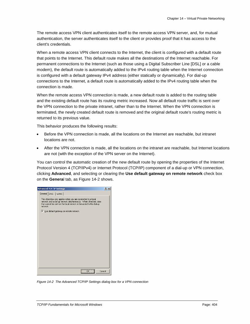
Chapter 14 – Virtual Private Networking
TCP/IP Fundamentals for Microsoft Windows Page: 404
The remote access VPN client authenticates itself to the remote access VPN server, and, for mutual
authentication, the server authenticates itself to the client or provides proof that it has access to the
client's credentials.
When a remote access VPN client connects to the Internet, the client is configured with a default route
that points to the Internet. This default route makes all the destinations of the Internet reachable. For
permanent connections to the Internet (such as those using a Digital Subscriber Line [DSL] or a cable
modem), the default route is automatically added to the IPv4 routing table when the Internet connection
is configured with a default gateway IPv4 address (either statically or dynamically). For dial-up
connections to the Internet, a default route is automatically added to the IPv4 routing table when the
connection is made.
When the remote access VPN connection is made, a new default route is added to the routing table
and the existing default route has its routing metric increased. Now all default route traffic is sent over
the VPN connection to the private intranet, rather than to the Internet. When the VPN connection is
terminated, the newly created default route is removed and the original default route's routing metric is
returned to its previous value.
This behavior produces the following results:
Before the VPN connection is made, all the locations on the Internet are reachable, but intranet
locations are not.
After the VPN connection is made, all the locations on the intranet are reachable, but Internet locations
are not (with the exception of the VPN server on the Internet).
You can control the automatic creation of the new default route by opening the properties of the Internet
Protocol Version 4 (TCP/IPv4) or Internet Protocol (TCP/IP) component of a dial-up or VPN connection,
clicking Advanced, and selecting or clearing the Use default gateway on remote network check box
on the General tab, as Figure 14-2 shows.
Figure 14-2 The Advanced TCP/IP Settings dialog box for a VPN connection

Chapter 14 – Virtual Private Networking
TCP/IP Fundamentals for Microsoft Windows Page: 405
VPN client users typically engage in either intranet or Internet communication, not both simultaneously.
These users do not have a problem with mutually exclusive access to either Internet locations or to
intranet locations. However, in some cases, users need simultaneous access to intranet and Internet
resources.
If your VPN users need simultaneous access to intranet and Internet resources when the VPN
connection is active, you can do one of the following:
Select the Use default gateway on remote network check box (the default setting), and allow Internet
access through the organization intranet. Internet traffic between the VPN client and Internet hosts
passes though firewalls or proxy servers as if the VPN client were physically connected to the
organization intranet. Although performance may be decreased, this method allows you to filter and
monitor Internet access according to your organization's network policies while the VPN client is
connected to the organization network.
When the VPN server assigns an IPv4 address to the VPN client, ensure that the subnet mask is set to
the same class-based subnet mask of the Internet address class of the IPv4 address. If the addressing
within your intranet is based on a single class-based address prefix, clear the Use default gateway on
remote network check box. The best example is when your intranet is using the private IPv4 address
prefix of 10.0.0.0/8.
If the addressing within your intranet is not based on a single class-based address prefix, you can use
one of the following solutions:
The DHCPInform message sent by VPN clients running Windows includes a request for the
Classless Static Routes DHCP option. On your DHCP server running Windows Server 2008 or
Windows Server 2003, configure the Classless Static Routes DHCP option for the appropriate
scope to contain a set of routes that represent the address space of your intranet. These routes are
automatically added to the routing table of the requesting VPN client.
By using the Connection Manager Administration Kit (CMAK) for Windows Server 2008 or
Windows Server 2003, you can configure specific routes as part of the Connection Manager profile
that you distribute to VPN users. You can also specify a Uniform Resource Locator (URL) that
contains the current set of organization intranet routes or additional routes beyond those that you
configure in the profile.
Site-to-Site
A site-to-site VPN connection (also known as a router-to-router VPN connection) is made by a router
and connects two portions of a private network. The VPN server provides a routed connection to the
network to which the server is attached. On a site-to-site VPN connection, the packets that either router
sends across the VPN connection typically do not typically originate at the routers.
The calling router (the VPN client) authenticates itself to the answering router (the VPN server), and, for
mutual authentication, the answering router authenticates itself to the calling router or provides proof
that it has access to the calling router's credentials.
Site-to-site VPN connections can be initiated by only one router (a one-way initiated VPN connection)
or by either router (a two-way initiated VPN connection). One-way initiated connections are well suited
to a spoke-and-hub topology in which only the branch office router can initiate the connection. Site-to-

Chapter 14 – Virtual Private Networking
TCP/IP Fundamentals for Microsoft Windows Page: 406
site VPN connections can be permanent (always connected) or on-demand (a router makes a
connection when it has traffic to send and disconnects after a configured idle timeout).
To support site-to-site connections, Routing and Remote Access in Windows Server 2008 and
Windows Server 2003 allows you to create demand-dial interfaces. A demand-dial interface is a logical
interface that represents the point-to-point connection between the two routers. You can use a demand-
dial interface in the same way as a physical interface. For example, you can assign routes and
configure packet filters on demand-dial interfaces.
Routing for site-to-site connections consists of a set of routes in the routing table of both the calling
router and the answering router. These routes summarize the addresses that are available across the
site-to-site connection. Each separate route specifies:
An address prefix (the combination of the destination and a subnet mask)
The routing metric
A demand-dial interface
If each router in a site-to-site connection has the set of routes that represent the addresses available
across the site-to-site connection, all of the locations on the intranet consisting of multiple sites are
reachable from each site.

Chapter 14 – Virtual Private Networking
TCP/IP Fundamentals for Microsoft Windows Page: 407
VPN Protocols
Computers running Windows Vista, Windows XP, Windows Server 2008, or Windows Server 2003 use
the following protocols to create VPN connections:
Point-to-Point Protocol (PPP)
PPTP
L2TP/IPsec
Computers running Windows Vista with Service Pack 1 and later or Windows Server 2008 also use
SSTP.
Point-to-Point Protocol (PPP)
PPTP and L2TP depend heavily on the features specified for PPP, which was designed to send data
across dial-up or dedicated point-to-point connections. For IPv4, PPP encapsulates IPv4 packets within
PPP frames and then transmits the packets across a point-to-point link. PPP was originally defined as
the protocol to use between dial-up clients and remote access servers.
The four phases of negotiation in a PPP connection are the following:
Phase 1: PPP Link Establishment
Phase 2: User Authentication
Phase 3: PPP Callback Control
Phase 4: Invoking Network Layer Protocol(s)
Each of these four phases must complete successfully before the PPP connection can transfer user
data.
Windows Vista and Windows Server 2008 support IPv6 traffic over PPP links. Neither Windows
Server 2003 nor Windows XP supports IPv6 traffic over PPP links, so you cannot send native IPv6
traffic across a dial-up or VPN connection from a computer running one of these operating systems.
You can, however, send tunneled IPv6 traffic that is encapsulated with an IPv4 header. For more
information about IPv6 tunneling, see Chapter 15 "IPv6 Transition Technologies."
Phase 1: PPP Link Establishment
PPP uses the Link Control Protocol (LCP) to establish, maintain, and terminate the logical point-to-point
connection. During Phase 1, basic communication options are selected. For example, authentication
protocols are selected, but they are not used for authentication until the connection authentication
phase (Phase 2). Similarly, during Phase 1, the two peers negotiate the use of compression or
encryption. The actual choice of compression and encryption algorithms and other details occurs during
Phase 4.
Phase 2: User Authentication
In Phase 2, the client computer sends the user’s credentials to the remote access server. An
authentication scheme should provide protection against replay attacks and remote client
impersonation. A replay attack occurs when an attacker monitors a successful connection and uses

Chapter 14 – Virtual Private Networking
TCP/IP Fundamentals for Microsoft Windows Page: 408
captured packets to play back the remote client’s response so that the attacker can gain an
authenticated connection. Remote client impersonation occurs when an attacker takes over an
authenticated connection.
Windows Server 2003 and Windows XP support the following PPP authentication protocols:
Password Authentication Protocol (PAP)
PAP is a plaintext password authentication mechanism that provides no protection from an attacker
that captures a PAP authentication exchange.
Challenge-Handshake Authentication Protocol (CHAP)
CHAP is an encrypted password authentication mechanism that avoids transmitting the password
on the connection.
Microsoft Challenge-Handshake Authentication Protocol (MS-CHAP)
MS-CHAP is an encrypted password authentication mechanism similar to CHAP, but MS-CHAP is
more secure.
MS-CHAP version 2 (MS-CHAP v2)
MS-CHAP v2 is an enhanced version of MS-CHAP that provides stronger protection for the
exchange of user name and password credentials, determination of encryption keys, and mutual
authentication.
Extensible Authentication Protocol (EAP)
EAP is a PPP authentication infrastructure that allows authentication mechanisms to be installed on
PPP clients and servers. During the authentication phase, EAP does not authenticate users. Phase
2 for EAP only negotiates the use of a common EAP authentication mechanism known as an EAP
type. The actual authentication for the negotiated EAP type is performed during Phase 4.
Windows Vista and Windows Server 2008 no longer support the MS-CHAP authentication protocol.
During Phase 2 of PPP link configuration, the VPN server running Windows Server 2008 or Windows
Server 2003 collects the authentication credentials and then validates them against one of the
following:
The VPN server's own user accounts database (if the VPN server is not a member of a domain)
A domain controller for Active Directory (if the VPN server is a member of a domain)
A Remote Authentication Dial-in User Service (RADIUS) server
A VPN server running Windows Vista or Windows XP validates authentication credentials against the
local user account database.
VPN connections that are based on PPTP require the use of MS-CHAP, MS-CHAP v2, or the EAP-
Transport Layer Security (TLS) authentication protocol. These authentication methods generate
encryption key material that is used to encrypt the data sent over the PPTP-based VPN connection.
L2TP/IPsec connections can use any of the authentication protocols because the authentication
protocol exchange is encrypted with IPsec. However, the use of MS-CHAP v2 or EAP-TLS is
recommended because they are the most secure user authentication protocols and they provide mutual
authentication.
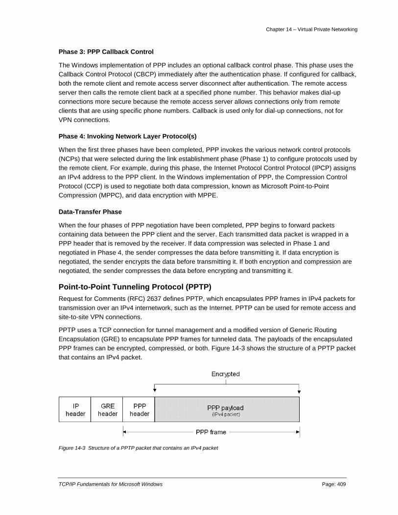
Chapter 14 – Virtual Private Networking
TCP/IP Fundamentals for Microsoft Windows Page: 409
Phase 3: PPP Callback Control
The Windows implementation of PPP includes an optional callback control phase. This phase uses the
Callback Control Protocol (CBCP) immediately after the authentication phase. If configured for callback,
both the remote client and remote access server disconnect after authentication. The remote access
server then calls the remote client back at a specified phone number. This behavior makes dial-up
connections more secure because the remote access server allows connections only from remote
clients that are using specific phone numbers. Callback is used only for dial-up connections, not for
VPN connections.
Phase 4: Invoking Network Layer Protocol(s)
When the first three phases have been completed, PPP invokes the various network control protocols
(NCPs) that were selected during the link establishment phase (Phase 1) to configure protocols used by
the remote client. For example, during this phase, the Internet Protocol Control Protocol (IPCP) assigns
an IPv4 address to the PPP client. In the Windows implementation of PPP, the Compression Control
Protocol (CCP) is used to negotiate both data compression, known as Microsoft Point-to-Point
Compression (MPPC), and data encryption with MPPE.
Data-Transfer Phase
When the four phases of PPP negotiation have been completed, PPP begins to forward packets
containing data between the PPP client and the server. Each transmitted data packet is wrapped in a
PPP header that is removed by the receiver. If data compression was selected in Phase 1 and
negotiated in Phase 4, the sender compresses the data before transmitting it. If data encryption is
negotiated, the sender encrypts the data before transmitting it. If both encryption and compression are
negotiated, the sender compresses the data before encrypting and transmitting it.
Point-to-Point Tunneling Protocol (PPTP)
Request for Comments (RFC) 2637 defines PPTP, which encapsulates PPP frames in IPv4 packets for
transmission over an IPv4 internetwork, such as the Internet. PPTP can be used for remote access and
site-to-site VPN connections.
PPTP uses a TCP connection for tunnel management and a modified version of Generic Routing
Encapsulation (GRE) to encapsulate PPP frames for tunneled data. The payloads of the encapsulated
PPP frames can be encrypted, compressed, or both. Figure 14-3 shows the structure of a PPTP packet
that contains an IPv4 packet.
Figure 14-3 Structure of a PPTP packet that contains an IPv4 packet

Chapter 14 – Virtual Private Networking
TCP/IP Fundamentals for Microsoft Windows Page: 410
Layer Two Tunneling Protocol with IPsec (L2TP/IPsec)
RFC 2661 defines L2TP, which encapsulates PPP frames to be sent over IPv4, X.25, Frame Relay, or
Asynchronous Transfer Mode (ATM) networks. If you configure L2TP for IPv4 networks, you can use it
as a tunneling protocol over the Internet.
L2TP over IPv4 internetworks uses a User Datagram Protocol (UDP) header and a series of L2TP
messages for tunnel management. L2TP also uses UDP to send L2TP-encapsulated PPP frames as
the tunneled data. The payloads of encapsulated PPP frames can be encrypted, compressed, or both,
although the Windows implementation of L2TP does not use MPPE to encrypt the PPP payload. Figure
14-4 shows the structure of an L2TP packet that contains an IPv4 packet.
Figure 14-4 Structure of an L2TP packet that contains an IPv4 packet
The Windows implementation of L2TP uses IPsec with Encapsulating Security Payload (ESP) to
encrypt L2TP traffic. The combination of L2TP (the tunneling protocol) and IPsec (the method of
encryption) is known as L2TP/IPsec, as RFC 3193 describes. For more information about ESP, see
Chapter 13, "Internet Protocol Security and Packet Filtering."
Figure 14-5 shows the result after ESP is applied to an IPv4 packet that contains an L2TP frame.
Figure 14-5 Encryption of L2TP traffic using IPsec with ESP
Secure Socket Tunneling Protocol (SSTP)
PPTP and L2TP/IPsec traffic can have problems traversing firewalls, network address translators
(NATs), and Web proxies. SSTP in Windows Server 2008 and Windows Vista Service Pack 1 solves
these VPN connectivity problems by using HyperText Transfer Protocol (HTTP) over secure sockets
layer (SSL). SSL is also known as Transport Layer Security (TLS). HTTP over SSL on TCP port 443 is
the protocol that is used on the Web for collecting credit card numbers and other private data.
Whenever you connect to a Web address that begins with https:, you are using HTTP over SSL. Using
HTTP over SSL solves many VPN protocol connectivity problems because typical firewalls, NATs, and
Web proxies allow this type of traffic.

Chapter 14 – Virtual Private Networking
TCP/IP Fundamentals for Microsoft Windows Page: 411
SSTP uses an HTTP-over-SSL session between VPN clients and servers to exchange encapsulated
IPv4 or IPv6 packets. Note that an HTTP-over-SSL-based remote access VPN connection is different
from the connection made by an application that uses HTTP over SSL. For example, Outlook® Web
Access (OWA) lets you access your Microsoft Exchange e-mail at your enterprise over the Internet.
OWA uses an HTTP over SSL-encrypted session, but this is not the same as a remote access
connection. Although you can view your e-mail with OWA, you can’t reach the location of an intranet
URL that is embedded within an Exchange e-mail message.
Unlike the PPTP and L2TP/IPsec protocols, SSTP does not support site-to-site VPN connections.
Figure 14-6 shows the structure of IPv4 or IPv6 packets that are sent over an SSTP-based VPN
connection.
Figure 14-6 Structure of SSTP packets
An IPv4 or IPv6 packet is first encapsulated with a PPP header and an SSTP header. The combination
of the IPv4 or IPv6 packet, the PPP header, and the SSTP header is encrypted by the SSL session. A
TCP header and an IPv4 header (for SSTP connections across the IPv4 Internet) or an IPv6 header (for
SSTP connections across the IPv6 Internet) are added to complete the packet.

Chapter 14 – Virtual Private Networking
TCP/IP Fundamentals for Microsoft Windows Page: 412
Remote Access VPN Connections
Both Windows Server 2003 and Windows XP include a remote access VPN client and a remote access
VPN server.
VPN Client Support
Windows Vista, Windows XP, Windows Server 2008, and Windows Server 2003 include a built-in VPN
client that supports PPTP and L2TP/IPsec. The VPN client in Windows Vista Service Pack 1 and
Windows Server 2008 also supports SSTP. You can configure a remote access VPN connection by
using either the Network Connections folder or Connection Manager.
Network Connections Folder
If you have a small number of VPN clients, you can manually configure a VPN connection for each
client. For clients running Windows Vista or Windows Server 2008, click the Set up a connection or
network task in the Network and Sharing Center. In the Set up a connection or network dialog box,
double-click Connect to a workplace and follow the Connect to a workplace wizard to create a VPN
connection.
For clients running Windows XP or Windows Server 2003, use the New Connection Wizard in the
Network Connections folder to create the VPN connection. Within the New Connection Wizard, click
Connect to the network at my workplace on the Network Connection Type page and click Virtual
Private Network connection on the Network Connection page.
Connection Manager
If you try to manually configure remote access VPN connections for thousands of clients in an
enterprise organization, you will probably experience one or more of the following problems:
The exact procedure to configure a VPN connection varies depending on the version of Windows
running on the client computer, so training end users to configure these connections will require
multiple sets of training materials.
To prevent configuration errors, the information technology (IT) staff should manually configure the VPN
connection rather than end users, placing a large administrative burden on the IT staff.
A VPN connection may need a double-dial configuration, in which a user must connect to the Internet
before connecting to the organization intranet. This requirement makes training end users even more
complicated.
To configure VPN connections for an enterprise organization, you can use the following components:
Connection Manager
Connection Manager Administration Kit
Connection Point Services
Connection Manager is a client dialer with advanced features that offer a superset of basic dial-up and
VPN networking. Windows Server 2008 and Windows Server 2003 includes a set of tools that you can

Chapter 14 – Virtual Private Networking
TCP/IP Fundamentals for Microsoft Windows Page: 413
use deliver pre-configured connections to network users. These tools are the Connection Manager
Administration Kit (CMAK) and Connection Point Services (CPS).
You can use CMAK to tailor the appearance and behavior of a connection made with Connection
Manager. With CMAK, you can develop client dialer and connection software that allows users to
connect to the network by using only the connection features that you define for them. Connection
Manager supports a variety of features that both simplify and enhance the deployment of connection
support for you and your users, and you can incorporate most of those features using the Connection
Manager Administration Kit Wizard. By using CMAK, you can create custom profiles that reflect the
identity, online help, and support infrastructure of your organization.
By using Connection Point Services (CPS), you can automatically create, distribute, and update custom
phone books. These phone books contain one or more Point of Presence (POP) entries, with each
POP entry storing a telephone number that provides dial-up access to a local ISP. Phone books give
users complete POP information so that, when they travel, they can connect to different Internet access
points rather than being restricted to a single POP.
Without the ability to update phone books (a task CPS handles automatically), users would have to
contact their organization's technical support staff for changes in POP information and to reconfigure
their client dialer software.
CPS has two components:
1. Phone Book Administrator
A tool used to create and maintain the phone book database and to publish new phone book
information to Phone Book Service.
2. Phone Book Service
An Internet Information Services (IIS) extension that automatically checks subscribers' or corporate
employees' current phone books and, if necessary, downloads a phone book update.
VPN Server Support
Using Routing and Remote Access in Windows Server 2008 and Windows Server 2003, you can
configure a VPN server that supports PPTP, L2TP/IPsec, and, for Windows Server 2008, SSTP.
To configure a computer running Windows Server 2008 to act as a VPN server, do the following:
1. Configure your server with a static IPv4 address on each of its intranet interfaces.
2. Click Start, point to Programs, point to Administrative Tools, and then click Server Manager.
3. In the console tree, right-click Roles, click Add Roles, and then click Next.
4. On the Select Server Roles page, select the Network Policy and Access Services check box, and
then click Next.
5. Follow the pages of the Add Roles wizard.
6. From the console tree of the Routing and Remote Access snap-in, right click the server name and
click Configure and Enable Routing and Remote Access.
7. Follow the pages of the Routing and Remote Access wizard to configure the server as a VPN server.

Chapter 14 – Virtual Private Networking
TCP/IP Fundamentals for Microsoft Windows Page: 414
To configure a computer running Windows Server 2003 to act as a VPN server, do the following:
1. Configure your server with a static IPv4 address on each of its intranet interfaces.
2. Click Start, point to Programs, point to Administrative Tools, and then click Routing And Remote
Access.
3. Right-click your server name, and then click Configure and enable Routing And Remote Access.
Click Next.
4. On the Configuration page, click Remote Access (dial-up or VPN), and then click Next.
5. On the Remote Access page, click VPN, and then click Next.
6. On the VPN Connection page, click the connection that corresponds to the interface connected to
the Internet or your perimeter network, and then click Next.
7. On the IP Address Assignment page, click Automatically if the VPN server should use DHCP to
obtain IPv4 addresses for remote access VPN clients. Or, click From a specified range of
addresses to use one or more static ranges of addresses. When IP address assignment is complete,
click Next.
8. On the Managing Multiple Remote Access Servers page, if you are using RADIUS for
authentication and authorization, click Yes, set up this server to work with a RADIUS server, and
then click Next.
On the RADIUS Server Selection page, configure the primary (mandatory) and alternate (optional)
RADIUS servers and the shared secret, and then click Next.
9. Click Finish.
10. When you are prompted to configure the DHCP Relay Agent, click OK.
11. In the tree of Routing and Remote Access, open IP Routing.
12. Right-click DHCP Relay Agent, and click Properties.
13. On the General tab of the DHCP Relay Agent Properties dialog box, add the IPv4 addresses that
correspond to your intranet DHCP servers, and click OK.
By default, Routing and Remote Access creates 128 PPTP and 128 L2TP/IPsec logical ports. If you
need more ports, configure the WAN Miniport (PPTP) or WAN Miniport (L2TP) devices from the
properties of the Ports object in the tree of Routing and Remote Access.
By default, the Routing and Remote Access Server Setup Wizard enables the MS-CHAP (for Windows
Server 2003 only), MS-CHAP v2, and EAP authentication protocols.
VPN Server Support in Windows Vista
To configure a computer running Windows XP as a remote access VPN server, press the ALT key to
display the menu bar, click File, and then click New Incoming Connection. Use the pages of the Allow
Connections to this Computer wizard to configure incoming connections.

Chapter 14 – Virtual Private Networking
TCP/IP Fundamentals for Microsoft Windows Page: 415
VPN Server Support in Windows XP
You can configure a computer running Windows XP as a remote access VPN server by running the
Create a New Connection Wizard in the Network Connections folder. On the Network Connection
Type page of the wizard, click Set up an advanced connection. On the Advanced Connection
Options page, click Accept incoming connections. These options will cause the computer running
Windows XP to act as a VPN server. However, the server will support only a single remote access
connection (dial-up, PPTP, or L2TP/IPsec-based).
IP Address Assignment and Routing and Remote Access
The VPN server obtains the IPv4 addresses that it assigns to VPN clients from either a DHCP server or
a static pool of IPv4 addresses. The type of address that Routing and Remote Access can assign to a
VPN client can be either an on-subnet address or an off-subnet address. The type of address that you
use can affect reachability, unless you make additional changes to the routing infrastructure.
The IPv4 addresses assigned to VPN clients can be from an:
On-subnet address range
An address range of an intranet subnet to which the VPN server is attached. The VPN server is
using an on-subnet address range when it obtains IPv4 addresses for VPN clients from a DHCP
server or when the manually configured static pool contains IPv4 addresses that are within the
range of addresses of an attached subnet.
The advantage to using on-subnet addresses is that they require no changes to routing
infrastructure.
Off-subnet address range
An address range that represents a different subnet that is logically attached to the VPN server.
The VPN server is using an off-subnet address range when the static pool contains IPv4 addresses
that are located on a separate subnet.
The advantage to using off-subnet addresses is that the IPv4 addresses of remote access clients
are more easily identified when they are connecting and communicating with resources on the
intranet. However, you must change the routing infrastructure so that the clients are reachable from
the intranet.
Obtaining IPv4 Addresses via DHCP
When configured to obtain IPv4 addresses from a DHCP server, Routing and Remote Access obtains
10 IPv4 addresses at a time. Routing and Remote Access attempts to obtain the first set of addresses
when the first remote access client connects, rather than when the Routing and Remote Access service
starts. Routing and Remote Access uses the first IPv4 address and allocates subsequent addresses to
clients as they connect. When clients disconnect, Routing and Remote Access can reassign their IPv4
addresses to other clients. When all 10 of the initial set of addresses are being concurrently used and
another remote access client attempts a connection, Routing and Remote Access obtains 10 more
addresses.
If the DHCP Client service cannot contact a DHCP server, the service returns addresses from the
Automatic Private IP Addressing (APIPA) range of 169.254.0.0/16 (from 169.254.0.1 through
169.254.255.254). APIPA addresses are off-subnet addresses that, by default, have no corresponding

Chapter 14 – Virtual Private Networking
TCP/IP Fundamentals for Microsoft Windows Page: 416
route in the intranet routing infrastructure. Remote access clients that are assigned an APIPA address
cannot communicate beyond the remote access server.
Routing and Remote Access attempts to obtain DHCP-allocated addresses using the interface that you
specify by opening the properties of the server running Routing and Remote Access, clicking the IPv4
or IP tab, and clicking the name of the interface in Adapter, as Figure 14-7 shows.
Figure 14-7 The IPv4 tab for the properties of the server running Routing and Remote Access
You can also specify this adapter on the Network Selection page of the Routing and Remote Access
Server Setup Wizard (if you have more than one intranet interface). If you specify the wrong adapter,
attempts to contact the DHCP server using that adapter could fail and return APIPA addresses. If you
specify Allow RAS to select adapter in Adapter, Routing and Remote Access randomly picks a LAN
interface to use at startup, which could also result in the use of the wrong adapter.
When the Routing and Remote Access service is stopped, it sends DHCPRelease messages to release
all of the IPv4 addresses obtained through DHCP.
Obtaining IPv4 Addresses from a Static Address Pool
A static address pool comprises one or more ranges of manually configured IPv4 addresses. When you
configure a static IPv4 address pool, the VPN server uses the first address in the first range. The server
allocates subsequent addresses to TCP/IP-based remote access clients as they connect. When the
clients disconnect, the server can reassign those addresses to other clients.
An address range in the static IPv4 address pool can be an on-subnet range, an off-subnet range, or a
mixture of on-subnet and off-subnet addresses.
If any of the addresses in any of the address ranges are off-subnet, you must add the route or routes
that summarize those addresses to the intranet routing infrastructure. This step helps ensure that traffic
destined to remote access clients is forwarded to the VPN server, which forwards the traffic to the
appropriate client. To provide the best summarization of address ranges for routes, you should choose
address ranges that you can express using a single address prefix. For example, the address range

Chapter 14 – Virtual Private Networking
TCP/IP Fundamentals for Microsoft Windows Page: 417
192.168.2.1 through 192.168.2.254 can be expressed as 192.168.2.0 with the subnet mask
255.255.255.0 (192.168.2.0/24).
The Process for Setting Up a Remote Access VPN Connection
The creation of a remote access VPN connection occurs in the following three steps:
1. Logical link setup
Creates the point-to-point link between the client and the server for the purposes of sending PPP
frames. The logical link used for VPN connections is the VPN tunnel that represents a logical point-
to-point link. If the client is running Windows, the message that appears during the logical link setup
is "Connecting."
2. PPP connection setup
Uses PPP protocols to negotiate the parameters of the PPP link, authenticate the credentials of the
remote access user, and negotiate the use of and the parameters for the protocols that will operate
over the PPP link. If the client is running Windows, the message that appears during the PPP
connection setup is "Verifying user name and password."
3. Remote access VPN client registration
The client obtains additional configuration parameters and registers itself in the Domain Name
System (DNS) and the Windows Internet Name Service (WINS) for name resolution. If the client is
running Windows, the message that appears during the remote access client registration is
"Registering your computer on the network."
Step 1: Logical Link Setup
The process for the logical link setup depends on whether the VPN connection is using PPTP or
L2TP/IPsec.
PPTP-based connections are established in the following two phases:
Phase 1
The client initiates a TCP connection from a dynamically allocated TCP port to TCP port 1723 on
the remote access VPN server.
Phase 2
The remote access VPN client and the server exchange a series of PPTP messages to negotiate
the use of a PPTP tunnel and a specific call identifier (ID) for the connection, which is used in the
PPTP GRE header.
When the PPTP connection setup begins, the client must already be connected to the Internet. If the
client is not connected, the user can create a dial-up connection to an ISP before initiating the PPTP
connection.
L2TP/IPsec-based connections are established in the following two phases:
Phase 1
The IPsec security associations (SAs) needed to protect IPsec-based communications and data are
negotiated and created. IPsec uses the Internet Key Exchange (IKE) protocol to negotiate the IKE

Chapter 14 – Virtual Private Networking
TCP/IP Fundamentals for Microsoft Windows Page: 418
main mode and quick mode SAs. The main mode SA protects IPsec negotiations. The quick mode
SAs—one for inbound packets and one for outbound packets—protect L2TP data using UDP port
1701. The main mode SA is authenticated using either certificates or a preshared key.
For certificate authentication, the VPN server sends the VPN client a list of acceptable root
certification authorities (CAs) from which the server will accept a certificate for authentication. The
VPN client responds with a certificate chain (ending at a root CA certificate for a root CA from the
list that the server sent) and its own list of acceptable root CAs. The server verifies the certificate
chain of the client and then sends its own certificate chain (ending at a root CA certificate for a root
CA from the list that the client sent) to the client. The client verifies the certificate chain that the
server sent.
For preshared key authentication, both the client and the server send a hash value that
incorporates the value of the preshared key. The server verifies the hash value that the client sent,
and the client verifies the hash value that the server sent.
For more information about main mode and quick mode negotiations, see Chapter 13, "Internet
Protocol Security and Packet Filtering."
Phase 2
The client and the server exchange a series of L2TP messages to negotiate the use of an L2TP
tunnel and a specific call ID to identify a connection within the L2TP tunnel.
When the L2TP/IPsec connection setup begins, the client must already be connected to the Internet. If
the client is not already connected, the user can create a dial-up connection to an ISP before initiating
the L2TP/IPsec connection.
SSTP-based connections are established with the following process:
1. The SSTP client establishes a TCP connection with the SSTP server between a dynamically-
allocated TCP port on the client and TCP port 443 on the server.
2. The SSTP client sends an SSL Client-Hello message, indicating that the client wants to create an
SSL session with the SSTP server.
3. The SSTP server sends its computer certificate to the SSTP client.
4. The SSTP client validates the computer certificate, determines the encryption method for the SSL
session, generates an SSL session key and then encrypts it with the public key of the SSTP server’s
certificate.
5. The SSTP client sends the encrypted form of the SSL session key to the SSTP server.
6. The SSTP server decrypts the encrypted SSL session key with the private key of its computer
certificate. All future communication between the SSTP client and the SSTP server is encrypted with
the negotiated encryption method and SSL session key.
7. The SSTP client sends an HTTP over SSL request message to the SSTP server.
8. The SSTP client negotiates an SSTP tunnel with the SSTP server.

Chapter 14 – Virtual Private Networking
TCP/IP Fundamentals for Microsoft Windows Page: 419
Step 2: PPP Connection Setup
The PPP connection process follows the four phases described in the "Point-to-Point Protocol" section
of this chapter.
Step 3: Remote Access VPN Client Registration
Each remote access VPN client sends a DHCPInform message to obtain additional TCP/IP
configuration parameters and performs name registration.
To obtain additional TCP/IP configuration parameters, the client performs the following process:
1. The client sends a DHCPInform message on the PPP link to the VPN server.
2. The VPN server, configured with the DHCP Relay Agent routing protocol component and at least one
IPv4 address of a DHCP server, relays the DHCPInform message to the DHCP server.
3. The DHCP server sends back a DHCPAck message that contains the requested options.
4. The VPN server relays the DHCPAck message to the client.
The principal use of the DHCPInform message is to obtain TCP/IP configuration parameters that are
not obtained using IPCP, such as the DNS domain name assigned to the VPN connection. Only remote
access VPN clients running Windows send the DHCPInform message.
Before nodes on the intranet can resolve the names of remote access VPN clients while they are
connected, the names and IPv4 addresses of the clients must be registered in the DNS and network
basic input/output system (NetBIOS) namespaces of the private network. Because a remote access
VPN client is typically assigned a different IPv4 address every time it connects, names in the
namespaces should be dynamic, rather than static. Dynamic name registration for remote access
clients consists of the following:
The remote access VPN client sends DNS dynamic update messages to its configured DNS server to
register its DNS names.
The client also sends NetBIOS name registration messages to its configured WINS server to register its
NetBIOS names.

Chapter 14 – Virtual Private Networking
TCP/IP Fundamentals for Microsoft Windows Page: 420
Site-to-Site VPN Connections
Routing and Remote Access in Windows Server 2008 and Windows Server 2003 supports demand-dial
routing (also known as dial-on-demand routing) over both dial-up connections (such as analog phone
lines or ISDN) and VPN connections. Demand-dial routing forwards packets across a PPP link, which is
represented inside Routing and Remote Access as a demand-dial interface. You can use demand-dial
interfaces to create on-demand connections across dial-up, non-permanent, or permanent media.
Demand-dial routing is not the same as remote access. Remote access connects a single computer to
a network, whereas demand-dial routing connects entire networks. However, both use PPP as the
protocol through which they negotiate and authenticate the connection and encapsulate the data sent
over it. With Routing and Remote Access in Windows Server 2008 and Windows Server 2003, you can
enable remote access and demand-dial connections separately. However, they share the following
attributes:
Dial-in properties of user accounts
Security (authentication protocols and encryption)
Windows or RADIUS authentication, authorization, and accounting
IPv4 address assignment and configuration
PPP features, such as MPPC and MPPE
Although the concept of demand-dial routing is fairly simple, the actual configuration is relatively
complex due to the following factors:
Connection endpoint addressing
The connection must be made over public data networks, such as the analog phone system or the
Internet. You specify the endpoint of the connection using a phone number for dial-up connections
and either a host name or an IPv4 address for VPN connections.
Authentication and authorization of the caller
Anyone who calls the router must be authenticated and authorized. Authentication is based on the
caller's set of credentials, which are passed to the router while the connection is being established.
The credentials that are passed must correspond to a Windows user account. The router authorizes
the connection based on the dial-in properties of the Windows user account and the remote access
policies for the organization network.
Differentiation between remote access VPN clients and calling routers
Both routing and remote access capabilities coexist on the same computer running Windows
Server 2008 or Windows Server 2003. Both remote access clients and demand-dial routers can
initiate a connection. For demand-dial connections, the computer initiating the demand-dial
connection is the calling router. The computer answering the connection attempt of a calling router
is the answering router. The computer running Windows Server 2008 or Windows Server 2003
must be able to distinguish between a connection attempt from a remote access client and one
from a calling router.

Chapter 14 – Virtual Private Networking
TCP/IP Fundamentals for Microsoft Windows Page: 421
The computer identifies the connection attempt as a remote access connection unless the
authentication credentials include a user name that matches the name of a demand-dial interface
on the answering router.
Configuration of both ends of the connection
You must configure both ends of the connection to enable two-way communication, even if only one
end of the connection always initiates a demand-dial connection. If you configure only one end of
the connection, packets will route in only one direction.
Configuration of static routes
You should not use dynamic routing protocols over on-demand demand-dial connections.
Therefore, you must add routes for address prefixes that are available across the demand-dial
interface as static routes to the routing tables of the demand-dial routers.
Configuring a Site-to-Site VPN Connection
To configure a site-to-site VPN connection, you must do the following:
Enable and configure Routing and Remote Access on the answering router.
Use the same procedure as described in the "VPN Server Support" section of this chapter.
Configure a demand-dial interface on the answering router.
Enable and configure Routing and Remote Access on the calling router.
Use the same procedure as described in the "VPN Server Support" section of this chapter.
Configure a demand-dial interface on the calling router.
Configuring a Demand-dial Interface
From either the answering router or the calling router, perform the following steps:
1. In the console tree of the Routing and Remote Access snap-in, right-click Network Interfaces, and
then click New Demand-dial Interface.
2. On the Welcome to the Demand-Dial Interface Wizard page, click Next.
3. On the Interface Name page, type a name for the demand-dial interface, and then click Next.
4. On the Connection Type page, click Connect using Virtual Private Networking (VPN), and then
click Next.
5. On the VPN Type page, click Automatic selection, Point to Point Tunneling Protocol (PPTP), or
Layer 2 Tunneling Protocol (L2TP) (as needed), and then click Next.
6. On the Destination Address page, type the IPv4 address of the other router's Internet interface, and
then click Next.
7. On the Protocols And Security page, select the Route IP packets on this interface and Add a
user account so that a remote router can dial in check boxes, and then click Next.
8. On the Static Routes for Remote Networks page, click Add to add static routes that are assigned
to the demand-dial interface and that represent the address prefixes of the site across the site-to-site
VPN connection (as needed). Click Next.

Chapter 14 – Virtual Private Networking
TCP/IP Fundamentals for Microsoft Windows Page: 422
9. On the Dial In Credentials page, type the password of the user account used by the calling router in
Password and Confirm password, and then click Next.
This step automatically creates a user account with the same name as the demand-dial interface that
you are creating. You are also configuring the router to use this account name in its dial in
credentials. When a calling router initiates a connection to an answering router, the calling router is
using a user account name that matches the name of a demand-dial interface. Therefore, the
answering router can determine that the incoming connection from the calling router is a demand-dial
connection, rather than a remote access connection.
10. On the Dial Out Credentials page, type the user name in User name, the user account domain
name in Domain, and the user account password in both Password and Confirm password.
If this router might call the other router, for a two-way-initiated, router-to-router VPN connection,
configure the name, domain, and password when this router is acting as the calling router. If this
router never calls the other router, you can type any name in User name and skip the rest of the
fields.
11. On the Completing the Demand-Dial Interface Wizard page, click Finish.
Connection Example for a Site-to-Site VPN
The complete configuration required for a site-to-site VPN connection is best illustrated by example.
Figure 14-8 shows an example configuration of two offices that must connect to each other's networks
across the Internet by using a site-to-site VPN connection.
Figure 14-8 Example configuration for connecting two offices across the Internet
The Seattle office has a computer that is running Windows Server 2008 and that acts as both a remote
access VPN server and a demand-dial router. All computers in the Seattle office are connected to the
172.16.1.0/24 network (subnet mask 255.255.255.0). The Seattle router (Router 1) has an Internet
interface that is assigned the public IPv4 address 131.107.21.178.
The New York office has a computer that is running Windows Server 2008 and that acts as both a
remote access VPN server and a demand-dial router. All computers in the New York office are
connected to the 172.16.2.0/24 network (subnet mask 255.255.255.0). The New York router (Router 2)

Chapter 14 – Virtual Private Networking
TCP/IP Fundamentals for Microsoft Windows Page: 423
has an Internet interface that is assigned the public IPv4 address 157.60.234.17. All computers in both
offices are in the example.com domain.
To configure demand-dial routing for the site-to-site VPN connection for this example, you must perform
the following steps:
Configure and enable Routing and Remote Access on Router 1.
Configure a demand-dial interface on Router 1 with the following settings:
Name: DD_NewYork
Destination Address: 157.60.234.17
Routes: 172.16.2.0 with the subnet mask 255.255.255.0
Dial In Credentials: User account name of DD_NewYork with the password of
h8#dW@93z~[Fc6$Q (example password)
Dial Out Credentials: User account name of DD_Seattle, domain name of example.com, and the
password of 7%uQv45l?p!kWy9* (example password)
Configure and enable Routing and Remote Access on Router 2.
Configure a demand-dial interface on Router 2.
Name: DD_Seattle
Destination Address: 131.107.21.178
Routes: 172.16.1.0/24
Dial In Credentials: User account name of DD_Seattle with the password 7%uQv45l?p!kWy9*
Dial Out Credentials: User account name of DD_NewYork, domain name of example.com, and the
password of h8#dW@93z~[Fc6$Q
Because you have configured a two-way initiated site-to-site VPN connection, you can initiate the
connection by performing the following steps on either Router 1 or Router 2:
1. In the tree of Routing and Remote Access, click Routing Interfaces.
2. In the details pane, right-click the demand-dial interface, and then click Connect.
Figure 14-9 shows the resulting demand-dial routing configuration in terms of the demand-dial
interfaces, static routes, and user accounts for the Seattle and New York offices.
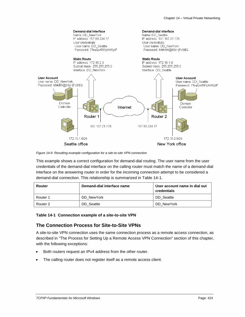
Chapter 14 – Virtual Private Networking
TCP/IP Fundamentals for Microsoft Windows Page: 424
Figure 14-9 Resulting example configuration for a site-to-site VPN connection
This example shows a correct configuration for demand-dial routing. The user name from the user
credentials of the demand-dial interface on the calling router must match the name of a demand-dial
interface on the answering router in order for the incoming connection attempt to be considered a
demand-dial connection. This relationship is summarized in Table 14-1.
Router Demand-dial interface name User account name in dial out
credentials
Router 1 DD_NewYork DD_Seattle
Router 2 DD_Seattle DD_NewYork
Table 14-1 Connection example of a site-to-site VPN
The Connection Process for Site-to-Site VPNs
A site-to-site VPN connection uses the same connection process as a remote access connection, as
described in "The Process for Setting Up a Remote Access VPN Connection" section of this chapter,
with the following exceptions:
Both routers request an IPv4 address from the other router.
The calling router does not register itself as a remote access client.

Chapter 14 – Virtual Private Networking
TCP/IP Fundamentals for Microsoft Windows Page: 425
Using RADIUS for Network Access Authentication
You can configure a VPN server running Windows Server 2008 or Windows Server 2003 to perform its
own authentication, authorization, and accounting (AAA) for VPN connections or to use Remote
Authentication Dial-in User Service (RADIUS). RFCs 2865 and 2866 define RADIUS, a widely deployed
protocol that enables centralized AAA for network access.
Originally developed for dial-up remote access, RADIUS is now supported by VPN servers, wireless
access points (APs), authenticating Ethernet switches, Digital Subscriber Line (DSL) access servers,
and other types of network access servers.
RADIUS Components
A RADIUS AAA infrastructure consists of the following components:
Access clients
Access servers (RADIUS clients)
RADIUS servers
User account databases
RADIUS proxies
Figure 14-10 shows these components.
Figure 14-10 The components of a RADIUS infrastructure
The following sections describe these components in detail.
Chapter 14 – Virtual Private Networking
TCP/IP Fundamentals for Microsoft Windows Page: 426
Access Clients
An access client requires access to a network or to another part of the network. Examples of access
clients are dial-up or VPN remote access clients, wireless clients, or LAN clients connected to an
authenticating switch. Access clients do not use the RADIUS protocol.
Access Servers
An access server provides access to a network. An access server using a RADIUS infrastructure is also
a RADIUS client, sending connection requests and accounting messages to a RADIUS server.
Examples of access servers are the following:
Network access servers (remote access servers) that provide remote access to an organization
network or to the Internet. An example is a computer that is running Windows Server 2008 or Windows
Server 2003 and Routing and Remote Access and that provides either dial-up or VPN-based remote
access to an organization's intranet.
Wireless APs that provide physical access to an organization's network by using wireless-based
transmission and reception technologies.
Switches that provide physical access to an organization's network by using LAN technologies such as
Ethernet.
RADIUS Servers
A RADIUS server receives and processes connection requests or accounting messages sent by
RADIUS clients or RADIUS proxies. During a connection request, the RADIUS server processes the list
of RADIUS attributes in the connection request. Based on a set of authorization rules and the
information in the user account database, the RADIUS server either authenticates and authorizes the
connection and sends back a RADIUS Access-Accept message or, if either authentication or
authorization fails, sends back a RADIUS Access-Reject message. The RADIUS Access-Accept
message can contain connection restrictions that the access server enforces for the duration of the
connection.
The Network Policy Server (NPS) component of Windows Server 2008 and the Internet Authentication
Service (IAS) component of Windows Server 2003 are industry-standard RADIUS servers.
User Account Databases
A user account database is a list of user accounts and their properties that a RADIUS server can check
to verify authentication credentials and to obtain user account properties that contain information about
authorization and connection parameters.
NPS and IAS can use the local Security Accounts Manager (SAM), a domain based on Microsoft
Windows NT 4.0 operating systems, or Active Directory as a user account database. For Active
Directory, NPS and IAS can provide authentication and authorization for user or computer accounts in
the domain of which the IAS server is a member, two-way trusted domains, and trusted forests with
domain controllers running Windows Server 2008 or Windows Server 2003.
If the user accounts for authentication reside in a different type of database, you can use a RADIUS
proxy to forward the authentication request to a RADIUS server that does have access to the user
account database.

Chapter 14 – Virtual Private Networking
TCP/IP Fundamentals for Microsoft Windows Page: 427
RADIUS Proxies
A RADIUS proxy routes RADIUS connection requests and accounting messages between RADIUS
clients (or other RADIUS proxies) and RADIUS servers (or other RADIUS proxies). A RADIUS proxy
uses information within the RADIUS message to route it to the appropriate RADIUS client or server.
You can use a RADIUS proxy as a forwarding point for RADIUS messages when AAA must occur at
multiple RADIUS servers in different organizations.
With the RADIUS proxy, the definition of RADIUS client and RADIUS server becomes blurred. A
RADIUS client to a RADIUS proxy can be an access server (that originates connection request or
accounting messages) or another RADIUS proxy. There can be multiple RADIUS proxies between the
originating RADIUS client and the final RADIUS server using chained RADIUS proxies. In a similar way,
a RADIUS server to a RADIUS proxy can be the final RADIUS server (which performs the
authentication and authorization evaluation) or another RADIUS proxy. Therefore, from a RADIUS
proxy perspective, a RADIUS client is the RADIUS entity from which the proxy receives RADIUS
request messages, and a RADIUS server is the RADIUS entity to which the proxy forwards RADIUS
request messages.
The NPS component of Windows Server 2008 and the IAS component of Windows Server 2003 are
industry-standard RADIUS proxies.
NPS or IAS as a RADIUS Server
You can use NPS or IAS as a RADIUS server to perform AAA for RADIUS clients. A RADIUS client can
be either an access server or a RADIUS proxy. Figure 14-11 shows NPS or IAS as a RADIUS server.
Figure 14-11 NPS or IAS as a RADIUS server

Chapter 14 – Virtual Private Networking
TCP/IP Fundamentals for Microsoft Windows Page: 428
The access server and the RADIUS proxy exchange RADIUS messages with the NPS or IAS server.
NPS or IAS uses a secure communications channel to communicate with an Active Directory domain
controller.
When NPS or IAS is used as a RADIUS server, it provides the following:
A central authentication and authorization service for all access requests that RADIUS clients and
RADIUS proxies send.
NPS or IAS uses an Active Directory–based domain or the local SAM to authenticate user
credentials for a connection attempt. NPS uses the dial-in properties of the account and network
policies to authorize a connection and enforce connection constraints. IAS uses the dial-in
properties of the account and remote access policies to authorize a connection and enforce
connection constraints.
A central accounting recording service for all accounting requests that RADIUS clients send.
For Windows Server 2008 or Windows Server 2003, accounting requests are stored in a local log
file or sent to a structured query language (SQL) server database for analysis.
You can use NPS or IAS as a RADIUS server in the following circumstances:
You use a Active Directory–based domain or the local SAM as your user account database for access
clients.
You use Routing and Remote Access in Windows Server 2008 or Windows Server 2003 on multiple
dial-up servers, VPN servers, or site-to-site routers and you want to centralize both the configuration of
remote access policies and the accounting of connection information.
You outsource your dial-up, VPN, or wireless access to a service provider. The access servers use
RADIUS to authenticate and authorize connections that members of your organization make.
You want to centralize AAA for a heterogeneous set of access servers.
To send RADIUS messages to an NPS or IAS-based RADIUS server, you must configure your access
servers or RADIUS proxies to use the NPS or IAS server as their RADIUS server. To receive RADIUS
messages from access servers or RADIUS proxies, you must configure the NPS or IAS server with
RADIUS clients. For example, if your VPN server is using NPS or IAS servers for RADIUS
authentication or accounting, you must do the following:
Configure the VPN server with RADIUS servers that correspond to the NPS or IAS servers.
Configure the NPS or IAS servers with a RADIUS client that corresponds to the VPN server.
To install NPS on a computer running Windows Server 2008, do the following:
1. Click Start, point to Programs, point to Administrative Tools, and then click Server Manager.
2. In the console tree, right-click Roles, click Add Roles, and then click Next.
3. On the Select Server Roles page, select the Network Policy and Access Services check box, and
then click Next.
4. Follow the pages of the Add Roles wizard.
To install IAS on a computer running Windows Server 2003, do the following:
Chapter 14 – Virtual Private Networking
TCP/IP Fundamentals for Microsoft Windows Page: 429
1. Click Start, click Control Panel, and then double-click Add or Remove Programs.
2. Click Add/Remove Windows Components.
3. In the Windows Components Wizard dialog box, click Networking Services, and then click
Details.
4. In the Networking Services dialog box, select the Internet Authentication Service check box, click
OK, and then click Next.
5. If prompted, insert the Windows Server 2003 product disk.
6. After IAS is installed, click Finish, and then click Close.
To create a RADIUS client on an NPS server, do the following:
1. Click Start, click Control Panel, double-click Administrative Tools, and then double-click Network
Policy Server.
2. In the tree, open RADIUS Clients and Server, right-click RADIUS Clients, and then click New
RADIUS Client.
To create a RADIUS client on an IAS server, do the following:
3. Click Start, click Control Panel, double-click Administrative Tools, and then double-click Internet
Authentication Service.
4. In the tree, right-click RADIUS Clients, and then click New RADIUS Client.
The New RADIUS Client Wizard will guide you through creating and configuring a RADIUS client.
Network and Remote Access Policies
For a connection attempt to be accepted, it must be both authenticated and authorized. Authentication
verifies the credentials of the access client. Authorization verifies that the connection attempt is allowed
and is granted on the basis of account dial-in properties and either network policies (for NPS) or remote
access policies (for IAS). Network and remote access policies are an ordered set of rules that define
how connections are either authorized or rejected. Each rule has one or more conditions, a set of profile
settings, and a setting for network or remote access permission.
When a connection is authorized, the settings of the network or remote access policy can specify a set
of connection restrictions. The dial-in properties of the account also provide a set of restrictions. Where
applicable, connection restrictions from the account properties override those from the network or
remote access policy.
Network or Remote Access Policy Conditions and Restrictions
Before authorizing the connection, network or remote access policies can validate a number of
connection settings, including the following:
Group membership
Type of connection
Time of day
Authentication method

Chapter 14 – Virtual Private Networking
TCP/IP Fundamentals for Microsoft Windows Page: 430
Identity of the access server
After authorizing the connection, network or remote access policies can specify connection restrictions,
including the following:
Idle timeout time
Maximum session time
Encryption strength
Authentication method
IPv4 packet filters
For example, you can have policies that specify different maximum session times for different types of
connections or groups. Additionally, you can have policies that specify restricted access for business
partners or vendors.
You can configure network or remote access policies either from the VPN server computer, if it is not
configured to use RADIUS, or from the NPS or IAS server computer.
NPS or IAS as a RADIUS Proxy
You can use NPS or IAS as a RADIUS proxy to route RADIUS messages between RADIUS clients
(access servers) and RADIUS servers that perform AAA for the connection attempt. When you use
NPA or IAS as a RADIUS proxy, NPS or IAS acts as a central switching or routing point through which
RADIUS access and accounting messages flow. NPS or IAS records information in an accounting log
about the messages that it forwards. Figure 14-12 shows NPS or IAS as a RADIUS proxy.

Chapter 14 – Virtual Private Networking
TCP/IP Fundamentals for Microsoft Windows Page: 431
Figure 14-12 NPS or IAS as a RADIUS proxy
Connection Request Processing
To determine whether a RADIUS client message should be processed locally or forwarded to another
RADIUS server, an NPS server running Windows Server 2008 or an IAS server running Windows
Server 2003 uses the following:
Connection request policies
For any incoming RADIUS request message, connection request policies determine whether the
NPS or IAS server processes the message locally or forwards it to another RADIUS server.
Connection request policies are rules that specify conditions and profile settings, which give you
flexibility to configure how the NPS or IAS server handles incoming authentication and accounting
request messages. With connection request policies, you can create a series of policies so that an
NPS or IAS server processes some RADIUS request messages locally (acting as a RADIUS
server) and forwards other types of messages to another RADIUS server (acting as a RADIUS
proxy).
Remote RADIUS server groups
When an NPS or IAS server forwards RADIUS messages, remote RADIUS server groups specify
the set of RADIUS servers to which the server forwards the messages. A remote RADIUS server
group is a named group that contains one or more RADIUS servers. When you configure a
connection request policy to forward RADIUS traffic, you must specify a remote RADIUS server
group. This group facilitates the common configuration of both a primary and a secondary RADIUS
server. You can specify various settings either to determine the order in which the servers are used
or to distribute the RADIUS messages across all servers in the group.
In Windows Server 2008, you can configure connection request policies from the Policies node and
remote RADIUS server groups from the RADIUS Clients and Servers folder in the Network Policy
Server snap-in.
In Windows Server 2003, you can configure connection request policies and remote RADIUS server
groups from the Connection Request Processing folder in the Internet Authentication Service snap-in.

Chapter 14 – Virtual Private Networking
TCP/IP Fundamentals for Microsoft Windows Page: 432
Chapter Summary
The chapter includes the following pieces of key information:
A virtual private network (VPN) extends a private network to encompass links across shared or public
networks like the Internet. With authentication, encapsulation, and encryption, you can use a VPN
connection to send data between two computers across a shared or public internetwork in a manner
that emulates the properties of a point-to-point private link.
A remote access VPN connection connects a single client computer to a private network across a
public or shared network. Either a default route or a set of routes that summarize the addresses of the
private intranet facilitates routing for remote access VPN connections.
A site-to-site VPN connection connects two portions of a private network across a public or shared
network. A set of routes associated with the demand-dial interfaces that represent the point-to-point
VPN connection facilitates routing for site-to-site VPN connections.
Windows Vista, Windows XP, Windows Server 2008, and Windows Server 2003 support both a VPN
client and a VPN server for remote access VPN connections. A computer running Windows Server
2008 or Windows Server 2003 can act as a calling or answering router in a site-to-site VPN connection.
RADIUS is a standard protocol that you can use for authorization, authentication, and accounting of
network access, including VPN connections. NPS in Windows Server 2008 and IAS in Windows
Server 2003 are the Microsoft implementations of a RADIUS server and proxy.
NPS uses network policies and IAS uses remote access policies to determine authorization of network
access.
Both NPS and IAS use connection request policies to determine whether the server should process an
incoming RADIUS request message locally or forward it to another RADIUS server.

Chapter 14 – Virtual Private Networking
TCP/IP Fundamentals for Microsoft Windows Page: 433
Chapter Glossary
access client – A network device that requires access to a network or another part of the network.
access server – A network device that provides access to a network. An access server that uses a
RADIUS server for authentication, authorization, and accounting is also a RADIUS client.
answering router – The router that answers the demand-dial connection attempt (the VPN server).
calling router – The router that initiates the demand-dial connection (the VPN client).
Layer Two Tunneling Protocol (L2TP) – A VPN tunneling protocol that uses UDP and an L2TP header
to encapsulate PPP frames sent across an IPv4 network.
Point-to-Point Protocol (PPP) – An industry standard suite of protocols for the use of point-to-point links
to transport multiprotocol packets.
Point-to-Point Tunneling Protocol (PPTP) – A VPN tunneling protocol that uses a TCP connection for
tunnel maintenance and a Generic Routing Encapsulation (GRE) header to encapsulate PPP frames.
RADIUS – See Remote Authentication Dial-In User Service (RADIUS).
RADIUS proxy – A RADIUS-capable device that routes RADIUS connection requests and accounting
messages between RADIUS clients (and RADIUS proxies) and RADIUS servers (and RADIUS
proxies).
RADIUS server – A server that receives and processes connection requests or accounting messages
sent by RADIUS clients or RADIUS proxies.
remote access VPN connection – A VPN connection that connects a single client computer to a private
network across a public or shared network.
Remote Authentication Dial-In User Service (RADIUS) – An industry standard protocol that you can use
to send messages between access servers, RADIUS servers, and RADIUS proxies to provide
authentication, authorization, and accounting (AAA) of network access.
Secure Socket Tunneling Protocol (SSTP) – A VPN tunneling protocol that uses a HyperText Transfer
Protocol (HTTP) over Secure Sockets Layer (SSL) session and an SSTP header to encapsulate PPP
frames.
site-to-site VPN connection – A VPN connection that connects two portions of a private network
together across a public or shared network.
user account database – A list of user accounts and their properties that a RADIUS server can check to
verify authentication credentials and obtain user account properties that contain information about
authorization and connection parameters.
virtual private network (VPN) – The extension of a private network that encompasses encapsulated,
encrypted, and authenticated links across shared or public networks. VPN connections can provide
remote access and routed connections to private networks over a public or shared network, such as the
Internet.
VPN – See virtual private network (VPN).
VPN client – A computer that initiates a connection to a VPN server.

Chapter 14 – Virtual Private Networking
TCP/IP Fundamentals for Microsoft Windows Page: 434
VPN server – A computer that accepts virtual private network (VPN) connections from VPN clients. A
VPN server can provide a remote access or a site-to-site VPN connection.

Chapter 15 – IPv6 Transition Technologies
TCP/IP Fundamentals for Microsoft Windows Page: 435
Chapter 15 – IPv6 Transition Technologies
Abstract
This chapter describes the mechanisms that aid in the transition of Internet Protocol version 4 (IPv4) to Internet Protocol
version 6 (IPv6) and the set of IPv6 transition technologies that are included with Microsoft Windows. Because the
deployment of IPv6-only environments will not replace IPv4-only environments in the near future, network
administrators must understand transition technologies that allow the concurrent use of IPv6 and IPv4 in a mixed
environment.

Chapter 15 – IPv6 Transition Technologies
TCP/IP Fundamentals for Microsoft Windows Page: 436
Chapter Objectives
After completing this chapter, you will be able to:
List and describe the different types of IPv4 and IPv6 nodes.
Describe the mechanisms for IPv4 to IPv6 transition.
List and describe the types of tunneling configurations.
Define the differences between configured and automatic tunneling.
Describe ISATAP in terms of its purpose, requirements, and addresses.
Describe 6to4 in terms of its purpose, requirements, and addresses.
Describe Teredo in terms of its purpose, requirements, and addresses.
List and describe the steps in migrating from IPv4 to IPv6.

Chapter 15 – IPv6 Transition Technologies
TCP/IP Fundamentals for Microsoft Windows Page: 437
Introduction to IPv6 Transition Technologies
Protocol transitions are typically done by installing and configuring the new protocol on all nodes within
the network and verifying that all node and router operations work successfully. Although this might be
possible in a small or medium sized organization, the challenge of making a rapid protocol transition in
a large organization is very difficult. Additionally, given the scope of the Internet, rapid protocol
transition is an impossible task.
The designers of IPv6 recognized that the transition from IPv4 to IPv6 would take years and that there
might be organizations or hosts within organizations that will continue to use IPv4 indefinitely.
Therefore, while migration is the long-term goal, equal consideration must be given to the interim
coexistence of IPv4 and IPv6 nodes.
RFC 2893 defines the following node types:
IPv4-only node
A node that uses only IPv4 and has only IPv4 addresses assigned. This node type does not
support IPv6. Most hosts and routers installed today are IPv4-only nodes.
IPv6-only node
A node that uses only IPv6 and has only IPv6 addresses assigned. This node type is only able to
communicate with IPv6 nodes and applications. This type of node is not common today, but will
become more prevalent as smaller devices such as cellular phones and handheld computing
devices use only the IPv6 protocol.
IPv6/IPv4 node
A node that uses both IPv4 and IPv6.
IPv4 node
A node that uses IPv4. An IPv4 node can be an IPv4-only node or an IPv6/IPv4 node.
IPv6 node
A node that uses IPv6. An IPv6 node can be an IPv6-only node or an IPv6/IPv4 node.
For coexistence to occur, all nodes (IPv4 or IPv6 nodes) can communicate using an IPv4 infrastructure,
an IPv6 infrastructure, or an infrastructure that is a combination of IPv4 and IPv6. True migration is
achieved when all IPv4 nodes are converted to IPv6-only nodes. However, for the foreseeable future,
practical migration is achieved when as many IPv4-only nodes as possible are converted to IPv6-only
nodes. IPv4-only nodes can communicate with IPv6-only nodes through an IPv4-to-IPv6 proxy or
translation gateway.

Chapter 15 – IPv6 Transition Technologies
TCP/IP Fundamentals for Microsoft Windows Page: 438
IPv6 Transition Mechanisms
To coexist with an IPv4 infrastructure and to provide an eventual transition to an IPv6-only
infrastructure, the following mechanisms are used:
Dual stack or dual IP layer architectures
DNS infrastructure
IPv6 over IPv4 tunneling
Dual Stack or Dual IP Layer Architectures
IPv6/IPv4 hosts can be based on a dual IP layer or dual stack architecture. In either architecture, the
following types of traffic are possible:
IPv4
IPv6
IPv6 traffic sent with an IPv4 header (IPv6 over IPv4 tunneling)
A dual IP layer contains a single implementation of Transport layer protocols such as TCP and UDP.
Figure 15-1 shows a dual IP layer architecture.
Figure 15-1 The dual IP layer architecture
The IPv6 protocol for Windows Vista and Windows Server 2008 uses the dual IP layer architecture. The
TCP/IP protocol driver in Windows Vista and Windows Server 2008, Tcpip.sys, contains both IPv4 and
IPv6 Internet layers.
Figure 15-2 shows the dual stack architecture.

Chapter 15 – IPv6 Transition Technologies
TCP/IP Fundamentals for Microsoft Windows Page: 439
Figure 15-2 The dual stack architecture
The IPv6 protocol for Windows Server 2003 and Windows XP uses the dual stack architecture. The
IPv6 protocol driver in Windows Server 2003 and Windows XP, Tcpip6.sys, contains a separate
implementation of TCP and UDP.
Both dual stack and dual IP layer architectures provide the same functionality for IPv6 transition.
DNS Infrastructure
A Domain Name System (DNS) infrastructure is needed for successful coexistence because of the
prevalent use of names rather than addresses to refer to network resources. Upgrading the DNS
infrastructure consists of populating the DNS servers with records to support IPv6 name-to-address and
address-to-name resolutions.
For name-to-address resolutions, the DNS infrastructure must be able to store AAAA records for IPv6
nodes that are populated either manually or dynamically.
For address-to-name resolutions (reverse queries), the DNS infrastructure must be able to store PTR
records in the IP6.ARPA domain for IPv6 nodes, populated either manually or dynamically.
Address Selection Rules
For name-to-address resolution, after the querying node obtains the set of addresses corresponding to
the name, the node must determine the set of addresses to choose as source and destination for
outgoing packets.
This is not an issue in today’s prevalent IPv4-only environments. However, in an environment in which
IPv4 and IPv6 coexist, the set of addresses returned in a DNS query may contain both IPv4 and IPv6
addresses. The typical querying IPv6/IPv4 host is configured with at least one IPv4 address and
multiple IPv6 addresses. Deciding which type of address (IPv4 vs. IPv6) and, for IPv6 addresses, a
source and the destination address that is matched in scope and purpose is not an easy task. For more
information, see Source and Destination Address Selection for IPv6. Default address selection rules are
defined in RFC 3484.
The default address selection rules for the IPv6 protocol in Windows are stored in the prefix policy
table, which you can view with the netsh interface ipv6 show prefixpolicy command. You can modify
the entries in the prefix policy table using the netsh interface ipv6 add|set|delete prefixpolicy
commands. By default, IPv6 addresses in DNS query responses are preferred over IPv4 addresses.

Chapter 15 – IPv6 Transition Technologies
TCP/IP Fundamentals for Microsoft Windows Page: 440
IPv6 Over IPv4 Tunneling
IPv6 over IPv4 tunneling is the encapsulation of IPv6 packets with an IPv4 header so that IPv6 packets
can be sent over an IPv4 infrastructure. Within the IPv4 header:
The IPv4 Protocol field is set to 41 to indicate an encapsulated IPv6 packet.
The Source and Destination fields are set to IPv4 addresses of the tunnel endpoints. The tunnel
endpoints are either manually configured or are automatically derived from the sending tunnel
interface and the next-hop address of the matching route for the destination IPv6 address in the
tunneled packet.
Figure 15-3 shows IPv6 over IPv4 tunneling.
Figure 15-3 IPv6 over IPv4 tunneling
Note IPv6 over IPv4 tunneling only describes an encapsulation of IPv6 packets with an IPv4 header so that IPv6 nodes are
reachable across an IPv4 infrastructure. Unlike tunneling for the Point-to-Point Tunneling Protocol (PPTP) and Layer Two Tunneling
Protocol (L2TP), there is no exchange of messages for tunnel setup, maintenance, or termination. Additionally, IPv6 over IPv4
tunneling does not provide security for tunneled IPv6 packets. For more information about PPTP and L2TP, see Chapter 14, "Virtual
Private Networking."
Tunneling Configurations
RFC 2893 defines the following tunneling configurations with which to tunnel IPv6 traffic between
IPv6/IPv4 nodes over an IPv4 infrastructure:
Router-to-router
In the router-to-router tunneling configuration, two IPv6/IPv4 routers connect two IPv6-capable
infrastructures over an IPv4 infrastructure. The tunnel endpoints span a logical link in the path
between the source and destination. The IPv6 over IPv4 tunnel between the two routers acts as a
single hop. Routes within each IPv6-capable infrastructure point to the IPv6/IPv4 router on the
edge.
Host-to-router or router-to-host
In the host-to-router tunneling configuration, an IPv6/IPv4 node that resides within an IPv4
infrastructure creates an IPv6 over IPv4 tunnel to reach an IPv6/IPv4 router. The tunnel endpoints

Chapter 15 – IPv6 Transition Technologies
TCP/IP Fundamentals for Microsoft Windows Page: 441
span the first segment of the path between the source and destination nodes. The IPv6 over IPv4
tunnel between the IPv6/IPv4 node and the IPv6/IPv4 router acts as a single hop.
In the router-to-host tunneling configuration, an IPv6/IPv4 router creates an IPv6 over IPv4 tunnel
across an IPv4 infrastructure to reach an IPv6/IPv4 node. The tunnel endpoints span the last
segment of the path between the source node and destination node. The IPv6 over IPv4 tunnel
between the IPv6/IPv4 router and the IPv6/IPv4 node acts as a single hop.
Host-to-host
In the host-to-host tunneling configuration, an IPv6/IPv4 node that resides within an IPv4
infrastructure creates an IPv6 over IPv4 tunnel to reach another IPv6/IPv4 node that resides within
the same IPv4 infrastructure. The tunnel endpoints span the entire path between the source and
destination nodes. The IPv6 over IPv4 tunnel between the IPv6/IPv4 nodes acts as a single hop.
On each IPv6/IPv4 node, an interface representing the IPv6 over IPv4 tunnel is created. IPv6 routes are
added that use the tunnel interface. Based on the sending tunnel interface, the route, and the
destination address, the sending node tunnels the IPv6 traffic to the next hop or to the destination. The
IPv4 address of the tunnel endpoint can be manually configured or automatically determined from the
next-hop address for the destination and the tunnel interface.
Types of Tunnels
RFC 2893 defines the following types of tunnels:
Configured
A configured tunnel requires manual configuration of tunnel endpoints. In a configured tunnel, the
IPv4 addresses of tunnel endpoints are not derived from the next-hop address corresponding to the
destination address.
Typically, router-to-router tunneling configurations are manually configured. The tunnel interface
configuration, consisting of the IPv4 addresses of the tunnel endpoints, must be manually specified
along with routes that use the tunnel interface.
To manually create configured tunnels for the IPv6 protocol for Windows, use the netsh interface
ipv6 add v6v4tunnel command.
Automatic
An automatic tunnel is a tunnel that does not require manual configuration. Tunnel endpoints are
determined by the use of logical tunnel interfaces, routes, and destination IPv6 addresses.
The IPv6 protocol for Windows Vista, Windows XP, Windows Server 2008, and Windows Server 2003
supports the following automatic tunneling technologies:
Intra-site Automatic Tunnel Addressing Protocol (ISATAP)
6to4
Teredo
The IPv6 protocol for Windows Server 2003 and Windows XP also supports automatic tunneling using
IPv6-compatible addresses and 6over4. For more information, see IPv6 Transition Technologies.

Chapter 15 – IPv6 Transition Technologies
TCP/IP Fundamentals for Microsoft Windows Page: 442
ISATAP
ISATAP is an address assignment and host-to-host, host-to-router, and router-to-host automatic
tunneling technology that provides unicast IPv6 connectivity between IPv6 hosts across an IPv4
intranet. ISATAP is described in RFC 4214. ISATAP hosts do not require any manual configuration and
create ISATAP addresses using standard address autoconfiguration mechanisms.
ISATAP can be used for communication between IPv6/IPv4 nodes on an IPv4 intranet. ISATAP
addresses use the interface identifier ::200:5EFE:w.x.y.z (in which w.x.y.z is a unicast public IPv4
address) or ::0:5EFE:w.x.y.z (in which w.x.y.z is a unicast private IPv4 address). The ISATAP interface
identifier can be combined with any 64-bit subnet prefix that is valid for IPv6 unicast addresses,
including global, unique local, and link-local prefixes. An example of a link-local ISATAP address is
FE80::5EFE:10.107.4.92.
By default, the IPv6 protocol for Windows Vista with no service packs installed, Windows Server 2003,
and Windows XP automatically configures link-local ISATAP addresses (with the address prefix
FE80::/64) on an ISATAP tunneling for each IPv4 address that is assigned to the node. Link-local
ISATAP addresses allow two hosts to communicate over an IPv4 network by using each other's link-
local ISATAP address. Windows Vista with Service Pack 1 and Windows Server 2008 do not
automatically configure link-local ISATAP addresses.
For example, Host A is configured with the IPv4 address of 10.40.1.29 and Host B is configured with
the IPv4 address of 192.168.41.30. Host A automatically configures the ISATAP address of
FE80::5EFE:10.40.1.29 and Host B automatically configures the ISATAP address of
FE80::5EFE:192.168.41.30. Figure 15-4 shows this example configuration.
Figure 15-4 An example ISATAP configuration
When Host A sends IPv6 traffic to Host B by using Host B's link-local ISATAP address, the source and
destination addresses for the IPv6 and IPv4 headers are as listed in Table 15-1.
Table 15-1 Example of IPv4 and IPv6 addresses for ISATAP
Field Value
IPv6 Source Address FE80::5EFE:10.40.1.29
IPv6 Destination Address FE80::5EFE:192.168.41.30
IPv4 Source Address 10.40.1.29

Chapter 15 – IPv6 Transition Technologies
TCP/IP Fundamentals for Microsoft Windows Page: 443
IPv4 Destination Address 192.168.41.30
To test connectivity, a user on Host A can use the following command to ping Host B with its link-local
ISATAP address:
ping FE80::5EFE:192.168.41.30%2
Because the destination of the ping command is a link-local address, the %ZoneID portion of the
command must be used to specify the interface index of the interface from which traffic is sent. In this
case, %2 specifies interface 2, which is the interface index assigned to the ISATAP tunneling interface
on Host A. The ISATAP tunneling interface uses the last 32-bits of the destination IPv6 address as the
destination IPv4 address and the locally assigned IPv4 address as the source IPv4 address.
Using an ISATAP Router
The use of link-local ISATAP addresses allows IPv6/IPv4 hosts on the same logical ISATAP subnet to
communicate with each other, but link-local addresses are not registered in DNS and cannot be used to
communicate with other IPv6 hosts on other subnets. To obtain additional subnet prefixes, ISATAP
hosts must perform router discovery and address autoconfiguration with an ISATAP router. To
communicate outside the logical subnet using non-link-local ISATAP-based addresses, ISATAP hosts
must tunnel their packets to an ISATAP router. Figure 15-5 shows an ISATAP router.
Figure 15-5 An ISATAP router
An ISATAP router is an IPv4/IPv6 router that performs the following:
Advertises subnet prefixes assigned to the logical ISATAP subnet on which ISATAP hosts are
located. ISATAP hosts use the advertised subnet prefixes to configure global ISATAP addresses.
Forwards packets between ISATAP hosts and hosts on other IPv6 subnets (optional).
The other subnets can be subnets in an IPv6-capable portion of the organization's network or the
IPv6 Internet.
When an ISATAP host receives a router advertisement from an ISATAP router, it performs address
autoconfiguration and configures additional IPv6 addresses on the ISATAP interface with the
appropriate interface ID.
If the ISATAP router advertises itself as a default router, the ISATAP host adds a default route (::/0)
using the ISATAP interface with the next-hop address set to the link-local ISATAP address of the
ISATAP router. When an ISATAP host sends packets destined to locations outside the logical ISATAP
subnet, they are tunneled to the IPv4 address of the ISATAP router. The ISATAP router then forwards
the IPv6 packet.

Chapter 15 – IPv6 Transition Technologies
TCP/IP Fundamentals for Microsoft Windows Page: 444
The IPv6 protocol for Windows Vista, Windows XP, Windows Server 2008, and Windows Server 2003
obtains the IPv4 address of the ISATAP router through one of the following:
The successful resolution of the name "ISATAP" to an IPv4 address.
The netsh interface isatap set router or netsh interface ipv6 isatap set router commands.
Resolving the ISATAP Name
When the IPv6 protocol for Windows starts, it attempts to resolve the name "ISATAP" to an IPv4
address using the following TCP/IP name resolution techniques:
Check the local host name.
Check the DNS client resolver cache, which includes the entries in the Hosts file in the
SystemRoot\system32\drivers\etc folder.
Form a fully qualified domain name and sending a DNS name query. For example, if the computer
running Windows is a member of the example.com domain (and example.com is the only domain name
in the search list), the computer sends a DNS query to resolve the name isatap.example.com.
Use Link-Local Multicast Name Resolution (LLMNR) to resolve the single-label name “ISATAP”
(Windows Vista and Windows Server 2008 only).
Convert the ISATAP name into the NetBIOS name "ISATAP <00>" and check the NetBIOS
name cache.
Send a NetBIOS name query to the configured Windows Internet Name Service (WINS) servers.
Send NetBIOS broadcasts.
Check the Lmhosts file in the SystemRoot\system32\drivers\etc folder.
If successful, the host sends an IPv4-encapsulated Router Solicitation message to the ISATAP router.
The ISATAP router responds with an IPv4-encapsulated Router Advertisement message containing
subnet prefixes to use for autoconfiguration of ISATAP-based addresses and, optionally, advertising
itself as a default router.
To ensure that at least one of these attempts is successful, you can do one or more of the following as
needed:
If the ISATAP router is a computer running Windows, name the computer ISATAP and it will
automatically register the appropriate records in DNS and WINS.
Manually create an address (A) record for the name "ISATAP" in the appropriate domains in DNS.
For example, for the example.com domain, create an A record for isatap.example.com with the
IPv4 address of the ISATAP router.
Manually create a static WINS record in WINS for the NetBIOS name "ISATAP <00>".
Add the following entry to the Hosts file of the computers that need to resolve the name ISATAP:
IPv4_Address ISATAP
Add the following entry to the Lmhosts file of the computers that need to resolve the name ISATAP:
IPv4_Address ISATAP
Chapter 15 – IPv6 Transition Technologies
TCP/IP Fundamentals for Microsoft Windows Page: 445
Using the netsh interface isatap set router Command
Although the automatic resolution of the ISATAP name is the recommended method for configuring the
IPv4 address of the ISATAP router, you can manually configure the name or IPv4 address of the
ISATAP router with the netsh interface isatap set router or netsh interface ipv6 isatap set router
commands. The syntax of these commands are:
netsh interface isatap set router AddressOrName
netsh interface ipv6 isatap set router AddressOrName
AddressOrName is the name or IPv4 address of the ISATAP router's intranet interface. For example, if
the ISATAP router's IPv4 address is 192.168.39.1, the command is:
netsh interface isatap set router 192.168.39.1
Setting up an ISATAP Router
A computer running Windows Vista, Windows XP, Windows Server 2008, or Windows Server 2003 can
be configured as an ISATAP router. Assuming that the router is already configured to forward IPv6
traffic on its LAN interfaces and has a default route that is configured to be published, the additional
commands that need to be issued on the router are:
netsh interface ipv6 isatap set router IPv4Address
netsh interface ipv6 set interface ISATAPInterfaceNameOrIndex forwarding=enabled
advertise=enabled
netsh interface ipv6 add route SubnetPrefix/PrefixLength ISATAPInterfaceNameOrIndex
publish=yes
The first command sets the IPv4 address of the ISATAP router’s LAN interface on the IPv4 network.
The second command enables forwarding and advertising on the ISATAP tunneling interface.
The third command enables the advertisement of a specific subnet prefix (SubnetPrefix/PrefixLength)
over the ISATAP tunneling interface. Use this command one or multiple times to advertise as many
subnet prefixes as you need. All the subnet prefixes configured using this command are included in the
Router Advertisement message sent back to the ISATAP host.

Chapter 15 – IPv6 Transition Technologies
TCP/IP Fundamentals for Microsoft Windows Page: 446
6to4
6to4 is an address assignment and router-to-router automatic tunneling technology that provides
unicast IPv6 connectivity between IPv6 sites and hosts across the IPv4 Internet. 6to4 uses the global
address prefix 2002:WWXX:YYZZ::/48. WWXX:YYZZ is the colon-hexadecimal representation of a
public IPv4 address (w.x.y.z) assigned to a site or host. The full 6to4 address is:
2002:WWXX:YYZZ:SubnetID:InterfaceID
6to4 is described in RFC 3056, which defines the following terms:
6to4 host
Any IPv6 host that is configured with at least one 6to4 address (a global address with the 2002::/16
prefix). 6to4 hosts do not require any manual configuration and create 6to4 addresses using
standard address autoconfiguration mechanisms.
6to4 router
An IPv6/IPv4 router that supports the use of a 6to4 tunnel interface and is typically used to forward
6to4-addressed traffic between the 6to4 hosts within a site and either other 6to4 routers or the IPv6
Internet through a 6to4 relay.
6to4 relay
An IPv6/IPv4 router that forwards 6to4-addressed traffic between 6to4 routers on the IPv4 Internet
and hosts on the IPv6 Internet.
Figure 15-6 shows 6to4 components.

Chapter 15 – IPv6 Transition Technologies
TCP/IP Fundamentals for Microsoft Windows Page: 447
Figure 15-6 6to4 components
Within a site, local IPv6 routers advertise 2002:WWXX:YYZZ:Subnet_ID::/64 subnet prefixes so that
hosts autoconfigure 6to4 addresses. IPv6 routers within the site deliver traffic between 6to4 hosts.
Hosts on individual subnets are automatically configured with a 64-bit subnet route for direct delivery to
neighbors and a default route with the next-hop address of the advertising router. IPv6 traffic that does
not match any of the subnet prefixes used within the site is forwarded to a 6to4 router on the site
border. The 6to4 router on the site border has a 2002::/16 route that is used to forward traffic to other
6to4 sites and a default route (::/0) that is used to forward traffic to a 6to4 relay.
In the example network shown in Figure 15-6, Host A and Host B can communicate with each other
because of a default route using the next-hop address of the 6to4 router in Site 1. When Host A
communicates with Host C in another site, Host A sends the traffic to the 6to4 router in Site 1 as IPv6
packets. The 6to4 router in Site 1, using the 2002::/16 route in its routing table and the 6to4 tunnel
interface, encapsulates the traffic with an IPv4 header and tunnels it to the 6to4 router in Site 2. The
6to4 router in Site 2 receives the tunneled traffic, removes the IPv4 header and, using the subnet prefix
route in its routing table, forwards the IPv6 packet to Host C.
For example, Host A resides on subnet 1 within Site 1 that uses the public IPv4 address of
157.60.91.123. Host C resides on subnet 2 within Site 2 that uses the public IPv4 address of
131.107.210.49. Table 2 lists the addresses in the IPv4 and IPv6 headers when the 6to4 router in Site 1
sends the IPv4-encapsulated IPv6 packet to the 6to4 router in Site 2.

Chapter 15 – IPv6 Transition Technologies
TCP/IP Fundamentals for Microsoft Windows Page: 448
Table 15-2 Example 6to4 addresses
Field Value
IPv6 Source Address 2002:9D3C:5B7B:1::1
IPv6 Destination Address 2002:836B:D231:2::3
IPv4 Source Address 157.60.91.123
IPv4 Destination Address 131.107.210.49
When you use 6to4 hosts, an IPv6 routing infrastructure within a site, a 6to4 router at the site boundary,
and a 6to4 relay, the following types of communication are possible:
A 6to4 host can communicate with other 6to4 hosts within the same site.
This type of communication is available by using the IPv6 routing infrastructure within the site,
which provides reachability to all hosts within the site. In Figure 15-6, this is the communication
between Host A and Host B.
A 6to4 host can communicate with 6to4 hosts in other sites across the IPv4 Internet.
This type of communication occurs when a 6to4 host forwards IPv6 traffic that is destined to a 6to4
host in another site to its local site 6to4 router. The local site 6to4 router tunnels the IPv6 traffic to
the 6to4 router at the destination site on the IPv4 Internet. The 6to4 router at the destination site
removes the IPv4 header and forwards the IPv6 packet to the appropriate 6to4 host by using the
IPv6 routing infrastructure of the destination site. In Figure 15-6, this is the communication between
Host A and Host C.
A 6to4 host can communicate with hosts on the IPv6 Internet.
This type of communication occurs when a 6to4 host forwards IPv6 traffic that is destined for an
IPv6 Internet host to its local site 6to4 router. The local site 6to4 router tunnels the IPv6 traffic to a
6to4 relay that is connected to both the IPv4 Internet and the IPv6 Internet. The 6to4 relay removes
the IPv4 header and forwards the IPv6 packet to the appropriate IPv6 Internet host by using the
IPv6 routing infrastructure of the IPv6 Internet. In Figure 15-6, this is the communication between
Host A and Host D.
All of these types of communication use IPv6 traffic without the requirement of obtaining either a direct
connection to the IPv6 Internet or a global address prefix from an Internet service provider (ISP).
6to4 Support in Windows
The 6to4 component of the IPv6 protocol for Windows provides 6to4 tunneling support. If there is a
public IPv4 address assigned to an interface on the host and a global prefix is not received in a router
advertisement, the 6to4 component:
Automatically configures 6to4 addresses on a 6to4 tunneling interface for all public IPv4 addresses
that are assigned to interfaces on the computer.
Automatically creates a 2002::/16 route that forwards all 6to4 traffic with a 6to4 tunneling interface.
All traffic forwarded by this host to 6to4 destinations is encapsulated with an IPv4 header.
Automatically performs a DNS query to obtain the IPv4 address of a 6to4 relay on the IPv4 Internet.
By default, the 6to4 component queries for the name 6to4.ipv6.microsoft.com. You can use the

Chapter 15 – IPv6 Transition Technologies
TCP/IP Fundamentals for Microsoft Windows Page: 449
netsh interface ipv6 6to4 set relay command to specify the DNS name to query. If the query is
successful, a default route is added using a 6to4 tunneling interface and the next-hop address is set
to the 6to4 address of the 6to4 relay.
The results of the 6to4 component autoconfiguration vary depending on the configuration of the host.
Figure 15-7 shows how 6to4 is configured for different types of hosts running Windows (except IPv6
host D).
Figure 15-7 6to4 for Windows hosts
For a host that is assigned a private IPv4 address or receives a router advertisement for a global prefix,
there are no 6to4 addresses assigned to the 6to4 tunneling interface. Addresses and routes are
autoconfigured based on the received router advertisement. This configuration corresponds to Host A,
Host B, and Host C in Figure 15-7.
A host that is assigned a public IPv4 address and does not receive a router advertisement for a global
prefix automatically configures a 6to4 address of the form 2002:WWXX:YYZZ::WWXX:YYZZ is on the
6to4 tunneling interface. The host adds a 2002::/16 route using the 6to4 tunneling interface and, if the
DNS query for the 6to4 relay is successful, adds a default route using the 6to4 address of the 6to4 relay
as the next hop. This type of host is a 6to4 host and performs its own tunneling like a 6to4 router. This
configuration corresponds to 6to4 host/router E in Figure 15-7, a host that is directly connected to the
IPv4 Internet.

Chapter 15 – IPv6 Transition Technologies
TCP/IP Fundamentals for Microsoft Windows Page: 450
A computer running Windows can automatically configure itself as a 6to4 router by utilizing the
configuration of the Internet Connection Sharing (ICS) feature. This configuration corresponds to 6to4
router 1 in Figure 15-7.
If ICS is enabled on an interface that is assigned a public IPv4 address, the 6to4 component
automatically:
Enables IPv6 forwarding on the 6to4 tunneling interface and the private interface.
The private interface is connected to a single-subnet intranet and uses private IPv4 addresses from
the 192.168.0.0/24 prefix.
Sends Router Advertisement messages on the private interface.
The router advertisements advertise the ICS computer as a default router and contain a 6to4
subnet prefix that is based on the public IPv4 address assigned to the public interface. The Subnet
ID in the 6to4 subnet prefix is set to the interface index of the interface on which the advertisements
are sent.
For example, for an ICS computer using the public IPv4 address of 131.107.23.89 and interface 5 as
the interface index of the private interface, the advertised prefix would be 2002:836B:1759:5::/64.
Private hosts receiving this router advertisement would create global addresses through normal
address autoconfiguration and add a 2002:836B:1759:5::/64 route for the local subnet and a default
route with a next-hop address of the link-local address of the ICS computer's private interface. Private
hosts can communicate with each other on the same subnet using the 2002:836B:1759:5::/64 route.
For all other destinations to other 6to4 sites or the IPv6 Internet, the 6to4 hosts forward the IPv6
packets to the ICS computer using the default route.
For traffic to other 6to4 sites, the ICS computer uses its 2002::/16 route and encapsulates the IPv6
traffic with an IPv4 header and sends it across the IPv4 Internet to another 6to4 router. For all other
IPv6 traffic, the ICS computer uses its default route and encapsulates the IPv6 traffic with an IPv4
header and sends it across the IPv4 Internet to a 6to4 relay.
To manually configure a computer running Windows as a 6to4 router, you must do the following:
Ensure that the 6to4 router computer has a public address assigned to its Internet interface and has not
received a Router Advertisement message from either an IPv6 router on an attached subnet or an
ISATAP router. If this is the case, the 6to4 component automatically adds a 2002::/16 route to the
routing table that uses the 6to4 tunneling interface and adds a default route that points to a 6to4 relay
on the IPv4 Internet.
Enable forwarding and advertising on the interfaces attached to your intranet. You can do this with the
following command:
netsh interface ipv6 set interface InterfaceNameOrIndex forwarding=enabled
advertise=enabled
Enable forwarding on the 6to4 tunneling interface. You can do this with the following command:
netsh interface ipv6 set interface 6to4InterfaceNameOrIndex forwarding=enabled
Add routes for 6to4 prefixes to the interfaces attached to your intranet and configure them to be
published. You can do this with the following command:
Chapter 15 – IPv6 Transition Technologies
TCP/IP Fundamentals for Microsoft Windows Page: 451
netsh interface ipv6 add route 2002:WWXX:YYZZ:SubnetID::/64 InterfaceNameOrIndex
publish=yes
WWXX:YYZZ is the colon-hexadecimal notation for w.x.y.z, the public IPv4 address that is
assigned to the interface that is attached to the Internet. SubnetID identifies an individual subnet
within the 6to4 site.
For example, a computer running Windows Server 2003 has three LAN interfaces with the following
configuration:
Local Area Connection is attached to the IPv4 Internet and is assigned the public IPv4 address
131.107.0.1.
Local Area Connection 2 is an intranet interface that is using interface index 5.
Local Area Connection 3 is an intranet interface that is using interface index 6.
To configure this computer as a 6to4 router, run the following commands:
netsh interface ipv6 set interface "Local Area Connection 2" forwarding=enabled
advertise=enabled
netsh interface ipv6 set interface "Local Area Connection 3" forwarding=enabled
advertise=enabled
netsh interface ipv6 set interface "6to4 Tunneling Pseudo-Interface" forwarding=enabled
netsh interface ipv6 add route 2002:836b:1:5::/64 "Local Area Connection 2" publish=yes
netsh interface ipv6 add route 2002:836b:1:6::/64 "Local Area Connection 3" publish=yes
For this example, the subnet prefix 2002:836b:1:5::/64 is advertised over Local Area Connection 2 and
the subnet prefix 2002:836b:1:6::/64 is advertised over Local Area Connection 3 (836b:1 is the
hexadecimal colon notation for the public IPv4 address 131.107.0.1). By convention, the subnet ID is
set to the interface index of the interface over which the prefix is advertised. You can specify any
subnet ID you want (from 0 to 0xffff).

Chapter 15 – IPv6 Transition Technologies
TCP/IP Fundamentals for Microsoft Windows Page: 452
Teredo
Teredo, also known as IPv4 network address translator (NAT) traversal (NAT-T) for IPv6, provides
address assignment and host-to-host automatic tunneling for unicast IPv6 connectivity across the IPv4
Internet, even when IPv6/IPv4 hosts are located behind one or multiple IPv4 NATs. Teredo is defined in
RFC 4380. To traverse IPv4 NATs, IPv6 packets are sent as IPv4-based User Datagram Protocol
(UDP) messages.
6to4 provides a similar function as Teredo. However, 6to4 router support is required in the edge device
that is connected to the Internet. 6to4 router functionality is not widely supported by IPv4 NATs. Even if
the edge NAT were 6to4-capable, 6to4 would still not work for configurations in which there are multiple
NATs between a site and the Internet.
Teredo resolves the issues of the lack of 6to4 functionality in modern-day NATs or multi-layered NAT
configurations by tunneling IPv6 packets between the hosts within the sites. In contrast, 6to4 uses
tunneling from the edge device. Tunneling from the hosts presents another issue for NATs: IPv4-
encapsulated IPv6 packets are sent with the Protocol field in the IPv4 header set to 41. Most NATs only
translate TCP or UDP traffic and must either be manually configured to translate other protocols or
have an installed NAT editor that handles the translation. Because Protocol 41 translation is not a
common feature of NATs, IPv4-encapsulated IPv6 traffic will not flow through typical NATs. Therefore,
the IPv6 packet is encapsulated as an IPv4 UDP message, containing both IPv4 and UDP headers.
UDP messages can be translated by most NATs and can traverse multiple layers of NATs.
Teredo is designed as a last resort transition technology for IPv6 connectivity. If native IPv6, 6to4, or
ISATAP connectivity is present between communicating nodes, Teredo is not used. As more IPv4
NATs are upgraded to support 6to4 and IPv6 connectivity becomes ubiquitous, Teredo will be used less
and less, until eventually it is not used at all.
Teredo in Windows Server 2003 Service Pack 1, Windows XP SP2, and Windows XP SP1 with the
Advanced Networking Pack for Windows XP works only over cone and restricted NATs.
A cone NAT stores a mapping between an internal (private) address and port number and an external
(public) address and port number. After the NAT translation table entry is in place, incoming traffic from
the Internet to the external address and port number is allowed from any source address and port
number.
A restricted NAT stores a mapping between an internal address and port number and an external
address and port number, for either specific external addresses or specific external addresses and port
numbers. An incoming packet from the Internet that does not match a NAT translation table entry for
both the external destination address and port number and a specific source external address or port
number is silently discarded.
There is an additional type of NAT, known as a symmetric NAT, which maps the same internal address
and port number to different external addresses and ports, depending on the external destination
address (for outgoing traffic). Teredo in Windows Server 2003 and Windows XP does not support
symmetric NATs.
Teredo Components
Figure 15-8 shows the set of components for Teredo connectivity.

Chapter 15 – IPv6 Transition Technologies
TCP/IP Fundamentals for Microsoft Windows Page: 453
Figure 15-8 Teredo components
The components of Teredo are the following:
Teredo client
An IPv6/IPv4 node that supports a Teredo tunneling interface through which packets are tunneled
to either other Teredo clients or nodes on the IPv6 Internet through a Teredo relay.
Teredo server
An IPv6/IPv4 node that is connected to both the IPv4 Internet and the IPv6 Internet. The role of the
Teredo server is to assist in the initial configuration of Teredo clients and to facilitate the initial
communication between either Teredo clients in different sites or between Teredo clients and IPv6-
only hosts on the IPv6 Internet.
Teredo relay
An IPv6/IPv4 router that can forward packets between Teredo clients on the IPv4 Internet and IPv6-
only hosts on the IPv6 Internet.
Teredo host-specific relay
An IPv6/IPv4 node that has an interface and connectivity to both the IPv4 Internet and the IPv6
Internet and can communicate directly with Teredo clients over the IPv4 Internet, without the need
for an intermediate Teredo relay. The connectivity to the IPv4 Internet can be through a public IPv4
address or through a private IPv4 address and a neighboring NAT. The connectivity to the IPv6

Chapter 15 – IPv6 Transition Technologies
TCP/IP Fundamentals for Microsoft Windows Page: 454
Internet can be through a direct connection to the IPv6 Internet or through an IPv6 transition
technology such as 6to4.
Windows Vista, Windows Server 2008, Windows Server 2003 with Service Pack 1 and later, Windows
XP with SP2 and later, and Windows XP with SP1 and the Advanced Networking Pack for Windows XP
include Teredo client and Teredo host-specific relay functionality. The Teredo host-specific relay
functionality is automatically enabled if a global IPv6 address has been assigned. A global address can
be assigned from a Router Advertisement message that is received from a native IPv6 router, an
ISATAP router, or a 6to4 router. If there is no global address configured, Teredo client functionality is
enabled.
Teredo Addresses
Teredo addresses have the format shown in Figure 15-9.
Figure 15-9 Teredo addresses
A Teredo address consists of the following:
Teredo prefix
The first 32 bits are for the Teredo prefix, which is the same for all Teredo addresses. The Microsoft
implementations of Teredo use 2001::/32 or 3FFE:831F::/32 (obsolete).
Teredo server IPv4 address
The next 32 bits contain the IPv4 public address of the Teredo server that assisted in the
configuration of this Teredo address.
Flags
The next 16 bits are reserved for Teredo flags. The only defined flag is the high-order bit known as
the Cone flag. The Cone flag is set when the Teredo client detects that it is located behind a cone
NAT.
Obscured external port
The next 16 bits store an obscured version of the external UDP port that corresponds to all Teredo
traffic for this Teredo client. When the Teredo client sends its initial packet to a Teredo server, the
source UDP port of the packet is mapped by the NAT to a different, external UDP port. All Teredo
traffic for the host uses the same external, mapped UDP port.
The external port is obscured by exclusive ORing (XORing) the external port with 0xFFFF. For
example, the obscured version of the external port 5000 in hexadecimal format is EC77 (5000
equals 0x1388, and 0x1388 XOR 0xFFFF = 0xEC77). Obscuring the external port prevents a NAT
from translating the external port contained within the payload of the packets that are being
forwarded.
Obscured external address

Chapter 15 – IPv6 Transition Technologies
TCP/IP Fundamentals for Microsoft Windows Page: 455
The last 32 bits store an obscured version of the external IPv4 address that corresponds to all
Teredo traffic for this Teredo client. Just like the external port, when the Teredo client sends its
initial packet to a Teredo server, the source IP address of the packet is mapped by the NAT to a
different, external address.
The external address is obscured by XORing the external address with 0xFFFFFFFF. For example,
the obscured version of the public IPv4 address 131.107.0.1 in colon-hexadecimal format is
7C94:FFFE (131.107.0.1 equals 0x836B0001, and 0x836B0001 XOR 0xFFFFFFFF =
0x7C94FFFE). Obscuring the external address prevents NATs from translating the external
address contained within the payload of the packets that are being forwarded.
How Teredo Works
For two Windows-based Teredo clients, the most crucial Teredo processes are those used for initial
configuration and communication with a peer in a different site.
Initial Configuration
Teredo clients perform initial configuration by sending a series of Router Solicitation messages to
multiple Teredo servers. Windows-based Teredo clients obtain the IPv4 addresses of Teredo servers
on the IPv4 Internet by performing a DNS query the name teredo.ipv6.microsoft.com. You can use the
netsh interface ipv6 set teredo servername=Name_or_IPv4_Address command to specify the DNS
name to query. The Teredo client uses the router advertisements to derive a Teredo address and
determine whether the client is behind a cone, restricted, or symmetric NAT. You can see what type of
NAT the Teredo client has discovered from the display of the netsh interface ipv6 show teredo
command.
Based on the received Router Advertisement messages, the Teredo client constructs its Teredo
address from the following:
The first 64 bits are set to the value included in the Prefix Information option of the received router
advertisement. The 64-bit prefix advertised by the Teredo server consists of the Teredo prefix
(2001::/32) and the public IPv4 address of the Teredo server (32 bits).
The next 16 bits are the Flags field with the high-order bit set to either 1 (cone NAT) or 0 (restricted
NAT).
The next 16 bits are set to the obscured external UDP port number for Teredo traffic.
The last 32 bits are set to the obscured external IPv4 address for Teredo traffic.
The external IPv4 address and UDP port number for Teredo traffic are included in an extra Teredo
header in the router advertisements sent by the Teredo servers.
Initial Communication Between Two Teredo Clients in Different Sites
The set of packets sent during the initial communication between Teredo clients located in different
sites depends on whether the Teredo clients are located behind cone NATs or restricted NATs.
When a Teredo client is located behind a cone NAT, the NAT translation table entries for Teredo traffic
for the Teredo client allows traffic from any source IP address or source UDP port. Therefore, a Teredo

Chapter 15 – IPv6 Transition Technologies
TCP/IP Fundamentals for Microsoft Windows Page: 456
client can send packets directly to another Teredo client behind a cone NAT without having to send
additional packets.
When a Teredo client is located behind a restricted NAT, the NAT translation table entries for Teredo
traffic for the Teredo client is only allowed from specific IPv4 addresses and UDP port numbers.
Therefore, when a Teredo client is located behind a restricted NAT, an initiating Teredo client must first
send packets to create a source-specific NAT mapping that allows the initiating Teredo client's traffic to
traverse the restricted NAT, prior to sending the initial communication packet.
Figure 15-10 shows the initial communication process between Teredo clients that are located in
different sites when both sites are using restricted NATs.
Figure 15-10 Process for sending an initial packet when two Teredo clients are located behind restricted NATs
To send an initial communication packet from Teredo Client A to Teredo Client B, the following process
is used:
1. Teredo Client A sends a bubble packet directly to Teredo Client B. A bubble packet contains no data
and is used to create or maintain NAT mappings. Because Teredo Client B is behind a restricted
NAT, Teredo traffic from an arbitrary source IPv4 address and UDP port number is not allowed
unless there is a source-specific NAT translation table entry. Assuming that there is none, the
restricted NAT silently discards the bubble packet. However, when the restricted NAT for Teredo
Client A forwarded the bubble packet, it created a source-specific NAT translation table entry that will
allow future packets sent from Teredo Client B to be forwarded to Teredo Client A.
2. Teredo Client A sends a bubble packet to Teredo Client B through Teredo Server 2 (Teredo Client
B's Teredo server). The IPv4 destination address in the bubble packet is set to the IPv4 address of

Chapter 15 – IPv6 Transition Technologies
TCP/IP Fundamentals for Microsoft Windows Page: 457
Teredo Server 2, which Teredo Client A determines from the third and fourth blocks of Teredo Client
B's Teredo address.
3. Teredo Server 2 forwards the bubble packet to Teredo Client B. The restricted NAT for Teredo Client
B forwards the packet because there is an existing source-specific mapping for Teredo traffic from
Teredo Server 2 (established by the initial configuration of Teredo Client B).
4. Teredo Client B responds to the bubble packet received from Teredo Client A with its own bubble
packet, which is sent directly to Teredo Client A. Because Teredo Client A's restricted NAT has a
source-specific mapping for Teredo traffic from Teredo Client B (as established by the initial bubble
packet sent from Teredo Client A in step 1), it forwards the bubble packet to Teredo Client A.
5. Upon receipt of the bubble packet from Teredo Client B, Teredo Client A determines that source-
specific NAT mappings exist for both NATs. Teredo Client A sends an initial communication packet
directly to Teredo Client B. Subsequent packets are sent directly between Teredo Client A and
Teredo Client B.
This process occurs transparently to the users at Teredo Client A and Teredo Client B.
There are additional initial communication processes for when the destination for the initial packet is on
the same link, on the IPv6 Internet, or with a Teredo host-specific relay. For more information, see
Teredo Overview.

Chapter 15 – IPv6 Transition Technologies
TCP/IP Fundamentals for Microsoft Windows Page: 458
Migrating to IPv6
The migration of IPv4 to IPv6 will be a long process. As a general guideline, to migrate from IPv4 to
IPv6, you must perform the following steps:
1. Begin upgrading your applications to be independent of IPv4 or IPv6.
For example, Windows Sockets applications might need be changed to use new Windows Sockets
application programming interfaces (APIs) so that name resolution, socket creation, and other
functions are independent of whether IPv4 or IPv6 is being used.
2. Update the DNS infrastructure to support IPv6 address and PTR records.
The DNS infrastructure might need to be upgraded to support the new AAAA records and PTR
records in the IP6.ARPA reverse domain.
3. Upgrade hosts to IPv6/IPv4 nodes.
Hosts must be upgraded to use both IPv4 and IPv6 in a dual IP layer or dual stack architecture. DNS
resolver support must also be updated to process DNS query results that contain both IPv4 and IPv6
addresses.
4. Deploy ISATAP.
This optional step provides tunneled IPv6 connectivity before native IPv6 connectivity is deployed
across your network.
5. Upgrade routing infrastructure for native IPv6 routing.
Routers must be upgraded and configured to support native IPv6 prefix advertisement and routing.
6. Convert IPv6/IPv4 nodes to IPv6-only nodes.
IPv6/IPv4 nodes can be upgraded to be IPv6-only nodes. This should be a long-term goal because it
will take years for current IPv4-only network devices to be upgraded to IPv6-only. For those IPv4-only
nodes that cannot be upgraded to IPv6/IPv4 or IPv6-only, employ translation gateways or proxies as
appropriate so that IPv4-only nodes can communicate with IPv6-only nodes.

Chapter 15 – IPv6 Transition Technologies
TCP/IP Fundamentals for Microsoft Windows Page: 459
Chapter Summary
The chapter includes the following pieces of key information:
IPv6/IPv4 nodes with a dual stack or dual IP architecture, DNS infrastructure, and IPv6 over IPv4
tunneling are used to coexist with an IPv4 infrastructure and to provide eventual migration to an IPv6-
only infrastructure.
A configured tunnel requires manual configuration of the tunnel endpoints. An automatic tunnel is a
tunnel that does not require manual configuration. Tunnel endpoints are determined from routes and
tunneling interfaces.
ISATAP is an address assignment and host-to-host, host-to-router, and router-to-host automatic
tunneling technology that provides unicast IPv6 connectivity between IPv6 hosts across an IPv4
intranet.
ISATAP addresses are composed of a valid 64-bit unicast address prefix and the interface identifier of
either ::200:5EFE:w.x.y.z (w.x.y.z is a unicast public IPv4 address) or ::0:5EFE:w.x.y.z (w.x.y.z is a
unicast private IPv4 address).
6to4 is an address assignment and router-to-router automatic tunneling technology that provides
unicast IPv6 connectivity between IPv6 sites and hosts across the IPv4 Internet.
6to4 addresses are based on the prefix 2002:WWXX:YYZZ::/48 (in which WWXX:YYZZ is the colon
hexadecimal representation of w.x.y.z, a public IPv4 address).
Teredo is an address assignment and host-to-host or host-to-router automatic tunneling technology that
provides unicast IPv6 connectivity across the IPv4 Internet when IPv6/IPv4 hosts are located behind
one or multiple IPv4 NATs.
To migrate from IPv4 to IPv6 you must upgrade your applications to be independent of IPv4 or IPv6,
update the DNS infrastructure to support IPv6 address records, upgrade hosts to IPv6/IPv4 nodes,
deploy ISATAP, upgrade your routing infrastructure for native IPv6 routing, and then convert IPv6/IPv4
nodes to IPv6-only nodes.

Chapter 15 – IPv6 Transition Technologies
TCP/IP Fundamentals for Microsoft Windows Page: 460
Chapter Glossary
_ISATAP name – See ISATAP name.
6to4 – An IPv6 transition technology that is used to provide unicast IPv6 connectivity between IPv6
sites across the IPv4 Internet. 6to4 uses a public IPv4 address to construct a global IPv6 address
prefix.
6to4 address – An address of the type 2002:WWXX:YYZZ:Subnet_ID:Interface_ID, where
WWXX:YYZZ is the colon hexadecimal representation of w.x.y.z (a public IPv4 address). A 6to4
address is used to represent a node for the 6to4 transition technology.
6to4 host – An IPv6 host that is configured with at least one 6to4 address (a global address with the
2002::/16 prefix). 6to4 hosts do not require manual configuration and create 6to4 addresses by using
standard address autoconfiguration mechanisms.
6to4 relay – An IPv6/IPv4 router that forwards 6to4-addressed traffic between 6to4 routers on the IPv4
Internet and hosts on the IPv6 Internet.
6to4 router – An IPv6/IPv4 router that supports the use of a 6to4 tunnel interface and is typically used
to forward 6to4-addressed traffic between the 6to4 hosts within a site and other 6to4 routers or 6to4
relays on the IPv4 Internet.
automatic tunnel – An IPv6 over IPv4 tunnel in which the tunnel endpoints are determined by the use
of logical tunnel interfaces and routes.
configured tunnel – An IPv6 over IPv4 tunnel in which the tunnel endpoints are determined by manual
configuration.
dual IP layer architecture – The architecture of an IPv6/IPv4 node in which a single implementation of
Transport layer protocols such as TCP and UDP operate over separate implementations of IPv4 and
IPv6.
dual stack architecture – The architecture of an IPv6/IPv4 node that consists of two separate protocol
stacks, one for IPv4 and one for IPv6, and each stack has its own implementation of the Transport layer
protocols (TCP and UDP).
host-to-host tunneling – IPv6 over IPv4 tunneling where the tunnel endpoints are two hosts. For
example, an IPv6/IPv4 node that resides within an IPv4 infrastructure creates an IPv6 over IPv4 tunnel
to reach another host that resides within the same IPv4 infrastructure.
host-to-router tunneling – IPv6 over IPv4 tunneling where the tunnel begins at a sending host and ends
at an IPv6/IPv4 router. For example, an IPv6/IPv4 node that resides within an IPv4 infrastructure
creates an IPv6 over IPv4 tunnel to reach an IPv6/IPv4 router.
Intra-site Automatic Tunnel Addressing Protocol (ISATAP) – An IPv6 transition technology that
provides unicast IPv6 connectivity between IPv6 hosts across an IPv4 intranet. ISATAP derives the
interface ID from an IPv4 address (public or private) assigned to a host.
IPv6 in IPv4 – See IPv6 over IPv4 tunneling.
IPv6 over IPv4 tunneling – The encapsulation of IPv6 packets with an IPv4 header so that IPv6 traffic
can be sent across an IPv4 infrastructure. In the IPv4 header, the Protocol field is set to 41.

Chapter 15 – IPv6 Transition Technologies
TCP/IP Fundamentals for Microsoft Windows Page: 461
IPv6/IPv4 node – A node that uses both IPv4 and IPv6.
IPv6-only node – A node that uses only IPv6 and is assigned only IPv6 addresses.
ISATAP – See Intra-site Automatic Tunnel Addressing Protocol (ISATAP).
ISATAP address – An address of the type UnicastAddressPrefix:200:5EFE:w.x.y.z (in which w.x.y.z is
a public IPv4 address) or UnicastAddressPrefix:0:5EFE:w.x.y.z (in which w.x.y.z is a private IPv4
address).
ISATAP host – A host that is assigned an ISATAP address.
ISATAP name – The name that by default is resolved by computers running Windows Vista, Windows
XP with Service Pack 1 and later, Windows Server 2008, or Windows Server 2003 to automatically
discover the IPv4 address of the ISATAP router. Computers running Windows XP with no service packs
installed by default attempt to resolve the name "_ISATAP".
ISATAP router – An IPv6/IPv4 router that responds to tunneled router solicitations from ISATAP hosts
and forwards traffic between ISATAP hosts and nodes on other IPv6 subnets.
router-to-host tunneling – IPv6 over IPv4 tunneling in which the tunnel begins at a forwarding router
and ends at an IPv6/IPv4 host. For example, an IPv6/IPv4 router creates an IPv6 over IPv4 tunnel to
reach an IPv6/IPv4 host that resides within an IPv4 infrastructure.
router-to-router tunneling – IPv6 over IPv4 tunneling in which the tunnel begins at a forwarding router
and ends at an IPv6/IPv4 router. For example, an IPv6/IPv4 router on the edge of an IPv6 network
creates an IPv6 over IPv4 tunnel to reach another IPv6/IPv4 router.

Chapter 15 – IPv6 Transition Technologies
TCP/IP Fundamentals for Microsoft Windows Page: 462

Chapter 16 – Troubleshooting TCP/IP
TCP/IP Fundamentals for Microsoft Windows Page: 463
Chapter 16 – Troubleshooting TCP/IP
Abstract
This chapter describes how to troubleshoot problems with connectivity, name resolution, and Transmission Control
Protocol (TCP) session creation using the set of tools and capabilities provided in Microsoft Windows operating
systems. A network administrator must know how to methodically analyze a TCP/IP-related networking problem in
terms of the various layers of the TCP/IP model and use the appropriate tools to be effective in isolating and resolving
issues with successful communication on an TCP/IP network.

Chapter 16 – Troubleshooting TCP/IP
TCP/IP Fundamentals for Microsoft Windows Page: 464
Chapter Objectives
After completing this chapter, you will be able to:
List the common questions to ask when troubleshooting.
List the set of TCP/IP troubleshooting tools provided with Windows and describe how each is used to
obtain troubleshooting information.
List and describe the guidelines, tools, and techniques for troubleshooting Internet Protocol version 4
(IPv4) communications including IPv4 connectivity, Domain Name System (DNS) name resolution for
IPv4 addresses, Network basic input/output system (NetBIOS) name resolution, and IPv4-based TCP
sessions.
List and describe the guidelines, tools, and techniques for troubleshooting Internet Protocol version 6
(IPv6) communication including IPv6 connectivity, DNS name resolution for IPv6 addresses, and IPv6-
based TCP sessions.

Chapter 16 – Troubleshooting TCP/IP
TCP/IP Fundamentals for Microsoft Windows Page: 465
Identifying the Problem Source
A logical approach is helpful when troubleshooting any problem. Some common questions to ask during
troubleshooting include the following:
What works?
What does not work?
How are the things that do and do not work related?
Have the things that do not work ever worked?
If so, what has changed since it last worked?
The answers to these questions can indicate where to begin troubleshooting, possibly allowing you to
isolate the component, layer, or configuration issue that is causing the problem.

Chapter 16 – Troubleshooting TCP/IP
TCP/IP Fundamentals for Microsoft Windows Page: 466
Windows Troubleshooting Tools
Windows provides a full set of configuration, administration, and diagnostic tools and services that can
be used to troubleshoot TCP/IP problems, as listed in Table 16-1.
Tool Description
Arp Allows viewing and editing of the Address Resolution Protocol
(ARP) cache.
Hostname Displays the host name of the computer.
Ipconfig Displays the current TCP/IP configuration for both IPv4 and
IPv6. Also used to manage Dynamic Host Configuration Protocol
(DHCP)-allocated IPv4 address configurations, display or flush
the DNS client resolver cache, and register DNS names.
Nbtstat Displays NetBIOS over TCP/IP (NetBT) configuration and allows
management of the NetBIOS name cache.
Netsh Configuration tool for many network services. For each network
service, there is a context containing commands specific for that
service. For the netsh interface ip, netsh interface ipv4, and
netsh interface ipv6 contexts, displays and administers TCP/IP
protocol settings on either the local computer or a remote
computer.
Netstat Displays protocol statistics and information on current TCP
connections.
Nslookup Performs DNS queries and displays the results.
Ping Sends Internet Control Message Protocol (ICMP) Echo or
Internet Control Message Protocol for IPv6 (ICMPv6) Echo
Request messages to test reachability.
Route Allows viewing of the IPv4 and IPv6 routing tables and editing of
the IPv4 routing table.
Tracert Sends ICMP Echo or ICMPv6 Echo Request messages to trace
the network route taken by IPv4 or IPv6 packets to a specific
destination.
Pathping Sends ICMP Echo or ICMPv6 Echo Request messages to trace
the route an IPv4 or IPv6 packet takes to a destination and
displays information on packet losses for each router and link in
the path.
SNMP service Provides status and statistical information to Simple Network
Management System (SNMP) management systems.
Event Viewer Records errors and events.
Performance Logs and Alerts Logs TCP/IP core protocol performance and sends alerts (the
SNMP service must be installed).
Network Monitor Captures and displays the contents of TCP/IP packets sent to
and from computers.
Netdiag Runs a series of diagnostics test on networking components.
Netdiag is installed as part of the Windows XP and Windows
Server 2003 Support Tools in the Support\Tools folder of the

Chapter 16 – Troubleshooting TCP/IP
TCP/IP Fundamentals for Microsoft Windows Page: 467
Windows XP or Windows Server 2003 product CD-ROM.
Telnet Tests TCP connection establishment between two nodes.
Ttcp Listens for and sends TCP segment data or UDP messages
between two nodes. Ttcp.exe is provided with Windows Server
2003 in the Valueadd\Msft\Net\Tools folder of the Windows
Server 2003 product CD-ROM.
Table 16-1 Tools and Services for Troubleshooting TCP/IP
Chapter 16 – Troubleshooting TCP/IP
TCP/IP Fundamentals for Microsoft Windows Page: 468
Troubleshooting IPv4
The following sections describe the tools and techniques used to identify a problem at successive
layers of the TCP/IP protocol stack that is using an IPv4 Internet layer. Depending on the type of
problem, you might do one of the following:
Start at the bottom of the stack and move up.
Start at the top of the stack and move down.
The following sections are organized from the top of the stack and describe how to:
Verify IPv4 connectivity.
Verify DNS name resolution for IPv4 addresses.
Verify NetBIOS name resolution.
Verify IPv4-based TCP sessions.
Although not specified in the following sections, you can also use Network Monitor to capture IPv4
traffic to troubleshoot many problems with IPv4-based TCP/IP communications. However, to correctly
interpret the display of IPv4 packets in Network Monitor, you must have an detailed knowledge of the
protocols included in each packet.
Verifying IPv4 Connectivity
You can use the following tasks to troubleshoot problems with IPv4 connectivity:
Repair the connection
Verify configuration
Manage configuration
Verify reachability
Check packet filtering
View and manage the IPv4 routing table
Verify router reliability
Repair the Connection
The Network Connection Repair feature can be used to quickly renew IPv4 network connection settings
in an attempt to correct common configuration problems. Network Connection Repair performs a series
of tasks that attempt to renew the connection as if it were just initialized. To access Network Connection
Repair, do the following:
1. Open the Network Connections folder.
2. Right-click the connection that you want to repair, and then click Repair.
You can also click Repair on the Support tab for the status of a network connection.
The tasks that are performed by Network Connection Repair are the following:

Chapter 16 – Troubleshooting TCP/IP
TCP/IP Fundamentals for Microsoft Windows Page: 469
Checks whether DHCP is enabled and, if enabled, sends a broadcast DHCPRequest message to
refresh the IPv4 address configuration.
Flushes the ARP cache. This is equivalent to the arp -d * command.
Flushes and reloads the DNS client resolver cache with entries from the Hosts file. This is equivalent to
the ipconfig /flushdns command.
Re-registers DNS names using DNS dynamic update. This is equivalent to the ipconfig /registerdns
command.
Flushes and reloads the NetBIOS name cache with #PRE entries in the Lmhosts file. This is equivalent
to the nbtstat -R command.
Releases and then re-registers NetBIOS names with the Windows Internet Name Service (WINS). This
is equivalent to the nbtstat -RR command.
Verify Configuration
To check the current IPv4 settings for the correct address configuration (when manually configured) or
an appropriate address configuration (when automatically configured), you can use the following:
ipconfig /all
The display of the ipconfig /all command includes IPv4 addresses, default gateways, and DNS
settings for all interfaces. The Ipconfig tool only works on the local computer.
netsh interface ip show config
The display of the netsh interface ip show config command includes DNS and WINS servers per
interface. Netsh can also be used to show the configuration of a remote computer by using the –r
RemoteComputerName command line option. For example, to display the configuration of the
remote computer named FILESRV1, use the netsh –r filesrv1 interface ip show config
command.
Support tab on the Status dialog box on a network connection
To get the status of a network connection, double-click the connection in the Network Connections
folder, and then click the Support tab. The Support tab lists the address type (DHCP or manually
configured), the IPv4 address, subnet mask, and default gateway. Click Details on the Support tab
to display the media access control (MAC) address, DHCP lease information, DNS servers, and
WINS servers.
Manage Configuration
To make changes to the IPv4 address configuration, you can use the following:
Network Connections folder
From the Network Connections folder, you can make changes to the properties of the Internet
Protocol Version 4 (TCP/IPv4) or Internet Protocol (TCP/IP) component for the appropriate network
connection.
netsh interface ip set commands

Chapter 16 – Troubleshooting TCP/IP
TCP/IP Fundamentals for Microsoft Windows Page: 470
You can use the netsh interface ip set address command to configure the address type (DHCP or
manually configured), the IPv4 address, subnet mask, and default gateway. You can use the netsh
interface ip set dns command to configure the source of DNS server addresses (DHCP or
manually configured), a DNS server address, and DNS registration behavior. You can use the
netsh interface ip set wins command to configure the source of WINS server addresses (DHCP
or manually configured) and a WINS server address.
You can also use the –r RemoteComputerName command line option of the Netsh tool to manage
the IPv4 configuration of a remote computer.
Ipconfig commands to manage DHCP addresses
You can use the following commands to manage DHCP addresses:
ipconfig /release
ipconfig /renew
ipconfig /showclassid
ipconfig /setclassid
For more information about using Ipconfig commands to manage DHCP address configurations, see
Chapter 6, "Dynamic Host Configuration Protocol."
Verify Reachability
To verify reachability with a local or remote destination, try the following:
Check and flush the ARP cache
To display the current contents of the ARP cache, use the arp –a command. To flush the ARP
cache, use the arp –d * command. This command also removes static ARP cache entries.
Ping the default gateway
Use the Ping tool to ping your default gateway by its IPv4 address. You can obtain the IPv4
address of your default gateway from the display of the ipconfig, netsh interface ip show config,
or route print commands. Pinging the default gateway tests whether you can reach local nodes
and whether you can reach the default gateway, which is used to forward IPv4 packets to remote
nodes. This step might not succeed if the default gateway is filtering all ICMP messages.
Ping a remote destination by its IPv4 address
If you are able to ping your default gateway, ping a remote destination by its IPv4 address. This
step might not succeed if the destination is filtering all ICMP messages. Filtering of ICMP messages
is prevalent on the Internet.
Trace the route to the remote destination
If you are unable to ping a remote destination by its IPv4 address, there might be a routing problem
between your node and the destination node. Use the tracert –d IPv4Address command to trace
the routing path to the remote destination. The –d command line option prevents the Tracert tool
from performing a DNS reverse query on every near-side router interface in the routing path, which
speeds up the display of the routing path. This step might not succeed if the intermediate routers or
Chapter 16 – Troubleshooting TCP/IP
TCP/IP Fundamentals for Microsoft Windows Page: 471
the destination are filtering all ICMP messages. Filtering of ICMP messages is prevalent on the
Internet.
Check Packet Filtering
The problem with reaching a destination node might be due to the configuration of Internet Protocol
security (IPsec) or packet filtering on the source node, intermediate routers, or destination node that is
preventing packets from being sent, forwarded, or received.
On the source node, check for the following:
Active connection security rules with the Windows Firewall with Advanced Security snap-in
Active IPsec policies with the IP Security Monitor snap-in
For computers running Windows Server 2008 or Windows Server 2003, Routing and Remote Access
IPv4 packet filters on routing interfaces with the Routing and Remote Access snap-in
On intermediate IPv4 routers that are running Windows Vista or Windows XP, check for the following:
Active connection security rules with the Windows Firewall with Advanced Security snap-in
Active IPsec policies with the IP Security Monitor snap-in
On intermediate IPv4 routers that are running Windows Server 2008 or Windows Server 2003 and
Routing and Remote Access, check for the following:
Active connection security rules with the Windows Firewall with Advanced Security snap-in
Active IPsec policies with the IP Security Monitor snap-in
Routing and Remote Access IPv4 packet filters on routing interfaces with the Routing and Remote
Access snap-in
NAT/Basic Firewall routing protocol component of Routing and Remote Access
On intermediate IPv4 routers or firewalls that are from third-party hardware vendors, check for the
configuration of packet filters—also called access lists—and IPsec policies and filters.
On the destination node that is running Windows, check for the following:
Active connection security rules with the Windows Firewall with Advanced Security snap-in
Active IPsec policies with the IP Security Monitor snap-in
Whether Internet Connection Firewall or Windows Firewall is enabled
TCP/IP filtering
On the destination node that is running Windows Server 2008 or Windows Server 2003 and Routing
and Remote Access, check for the following:
Active connection security rules with the Windows Firewall with Advanced Security snap-in
Active IPsec policies with the IP Security Monitor snap-in
Routing and Remote Access IPv4 packet filters on routing interfaces with the Routing and Remote
Access snap-in
NAT/Basic Firewall routing protocol component of Routing and Remote Access

Chapter 16 – Troubleshooting TCP/IP
TCP/IP Fundamentals for Microsoft Windows Page: 472
Whether Internet Connection Firewall or Windows Firewall is enabled
TCP/IP filtering
For more information about IPsec and packet filtering components, see Chapter 13, "Internet Protocol
Security (IPsec) and Packet Filtering."
View and Manage the Local IPv4 Routing Table
The inability to reach a local or remote destination might be due to incorrect or missing routes in the
IPv4 routing table. To view the IPv4 routing table, use the route print or netstat –r commands. Verify
that you have a route corresponding to your local subnet and, if a default gateway is configured, a
default route. If you have multiple default routes with the same lowest metric, then change your IPv4
configuration so that only one exists and is using the interface that connects to the network with the
largest number of subnets, such as the Internet.
To add a route to the IPv4 routing table, use the route add command. To modify an existing route, use
the route change command. To remove an existing route, use the route delete command.
Verify Router Reliability
If you suspect a problem with router performance, use the pathping –d IPv4Address command to trace
the route a packet takes to a destination and display information on packet losses for each router and
link in the path. The –d command line option prevents the Pathping tool from performing a DNS reverse
query on every near-side router interface in the routing path, which speeds up the display of the routing
path.
Verifying DNS Name Resolution for IPv4 Addresses
If reachability using IPv4 addresses works but reachability using host names does not, then you might
have a problem with host name resolution, which is typically an issue with configuration of the DNS
client or problems with DNS registration.
You can use the following tasks to troubleshoot problems with DNS name resolution:
Verify DNS configuration
Display and flush the DNS client resolver cache
Test DNS name resolution with the Ping tool
Use the Nslookup tool to view DNS server responses
Verify DNS Configuration
On the node having DNS name resolution problems, verify the following:
Host name
Primary DNS suffix
DNS suffix search list
Connection-specific DNS suffixes
DNS servers

Chapter 16 – Troubleshooting TCP/IP
TCP/IP Fundamentals for Microsoft Windows Page: 473
You can obtain this information from the display of the ipconfig /all command. To obtain information
about which DNS names should be registered in DNS, use the netsh interface ip show dns
command.
To register the appropriate DNS names as IPv4 address resource records (also known as A resource
records) with DNS dynamic update, use the ipconfig /registerdns command.
Display and Flush the DNS Client Resolver Cache
TCP/IP checks the DNS client resolver cache before sending DNS name queries. If a positive cache
entry for name exists, the corresponding IPv4 address is used. If a negative cache entry for the name
exists, DNS name queries are not sent.
To display the contents of the DNS client resolver cache, use the ipconfig /displaydns command. To
flush the contents of the DNS client resolver cache and reload it with the entries in the Hosts file, use
the ipconfig /flushdns command.
Test DNS Name Resolution with Ping
To test DNS name resolution, use the Ping tool and ping a destination by its host name or fully qualified
domain name (FQDN). The Ping tool display shows the FQDN and its resolved IPv4 address. If the
host on which the Ping tool is being used is using both IPv4 and IPv6 and the DNS query returns both
IPv4 and IPv6 addresses, the Ping tool will use IPv6 addresses before IPv4 addresses. To force the
Ping tool to use an IPv4 address, use the –4 Ping command option.
Use the Nslookup Tool to View DNS Server Responses
If the Ping tool is using the wrong IPv4 address, flush the DNS client resolver cache with the ipconfig
/flushdns command and use the Nslookup tool to determine the set of addresses returned in the DNS
Name Query Response message. At the Nslookup > prompt, use the set d2 command to display the
maximum amount of information about the DNS response messages. Then, use Nslookup to look up
the desired FQDN and display the details of the DNS response message. Look for A records in the
detailed display of the DNS response messages.
Verifying NetBIOS Name Resolution
If reachability using IPv4 addresses works but reachability using NetBIOS names does not, then you
might have a problem with NetBIOS name resolution, which is typically a problem with NetBIOS over
TCP/IP configuration or WINS registration.
The following tools and tasks can be used to troubleshoot problems with NetBIOS name resolution:
Verify NetBT configuration
Display and reload the NetBIOS name cache
Test NetBIOS name resolution with Nbtstat
Verify NetBIOS over TCP/IP Configuration
On the node having NetBIOS name resolution problems, verify the following:
NetBIOS computer name

Chapter 16 – Troubleshooting TCP/IP
TCP/IP Fundamentals for Microsoft Windows Page: 474
NetBIOS node type
Primary WINS server
Secondary WINS server
Whether NetBIOS over TCP/IP is disabled
You can obtain this information from the display of the ipconfig /all command. To obtain information
about the NetBIOS scope ID assigned to each interface, use the nbtstat -c command. To verify
whether Lmhosts lookup is enabled, check the WINS tab for the advanced properties of the Internet
Protocol Version 4 (TCP/IPv4) or Internet Protocol (TCP/IP) component.
To display the local NetBIOS name table, use the nbtstat –n command. To display the NetBIOS name
table of a remote computer, use the nbtstat –a ComputerName or nbtstat –A IPv4Address commands.
To release and re-register the NetBIOS names of the node in WINS, use the nbtstat -RR command.
Display and Reload the NetBIOS Name Cache
The NetBIOS name cache is checked before sending WINS or broadcast name queries. If an entry
exists for a resolved name, TCP/IP uses the corresponding IPv4 address. To display the contents of the
NetBIOS name cache, use the nbtstat -c command. To flush the contents of the NetBIOS name cache
and reload it with the #PRE entries in the Lmhosts file, use the nbtstat -R command.
Test NetBIOS Name Resolution with Nbtstat
To test NetBIOS name resolution, use the nbtstat –a ComputerName command. This command
displays the NetBIOS name table of a computer specified by its NetBIOS computer name.
Verifying IPv4-based TCP Sessions
If reachability and name resolution are working but you cannot establish a TCP session with a
destination host, use the following tasks:
Check for packet filtering
Verify TCP session establishment
Verify NetBIOS sessions
Check for Packet Filtering
As previously discussed in the "Verifying IPv4 Communications" section of this chapter, packet filtering
by the source node, intermediate routers, and the destination node can prevent TCP sessions from
completing. Use the information in the "Verifying IPv4 Communications" section of this chapter to check
for packet filtering or IPsec policies at the source node, intermediate routers and firewalls, and the
destination node.
In many cases, packet filtering is configured to allow specific types of traffic and discard all others, or to
discard specific types of traffic and accept all others. As an example of the former case, a firewall or
Web server might be configured to allow only HyperText Transfer Protocol (HTTP) traffic and discard all
other traffic destined for the Web server. This means that you will be able to view Web pages on the
Web server, but not ping the Web server or access its shared folders and files.

Chapter 16 – Troubleshooting TCP/IP
TCP/IP Fundamentals for Microsoft Windows Page: 475
Verify TCP Session Establishment
To verify that a TCP connection can be established using the known destination TCP port number, you
can use the telnet IPv4Address TCPPort command. For example, to verify whether the Web server
service on the computer with the IPv4 address of 131.107.78.12 is accepting TCP connections, use the
telnet 131.107.78.12 80 command.
If the Telnet tool is successful in creating a TCP connection, the command prompt window will clear
and, depending on the protocol, display some text. This window allows you to type in commands to the
service to which you have connected. Type Control-C to exit the Telnet tool. If the Telnet tool cannot
successfully create a TCP connection, it displays the message "Connecting To IPv4Address...Could not
open connection to the host, on port TCPPort: Connect failed".
To test TCP connections, you can also use Port Query, a free tool from Microsoft to help troubleshoot
TCP/IP connectivity issues for specific types of TCP and UDP traffic. Port Query has a command-line
version (Portqry.exe) (available at PortQry Command Line Port Scanner Version 2.0) and a graphical
user interface version (Portqueryui.exe) (available at PortQryUI - User Interface for the PortQry
Command Line Port Scanner). Both versions run on Windows XP and Windows Server 2003-based
computers.
Another tool that you can use to test TCP connection establishment is Test TCP (Ttcp). With Ttcp, you
can both initiate TCP connections and listen for TCP connections. You can also use the Ttcp tool for
UDP traffic. With Ttcp, you can configure a computer to listen on a specific TCP or UDP port without
having to install the application or service on the computer. This allows you to test network connectivity
for specific traffic before the services are in place.
For more information about Port Query and Ttcp, see Testing Network Paths for Common Types of
Traffic.
Verify NetBIOS Sessions
To verify that you have established NetBIOS sessions, you can use the nbtstat –s command, which
displays the NetBIOS session table.

Chapter 16 – Troubleshooting TCP/IP
TCP/IP Fundamentals for Microsoft Windows Page: 476
Troubleshooting IPv6
The following sections describe the tools and techniques used to identify a problem at successive
layers of the TCP/IP protocol stack using an IPv6 Internet layer. Depending on the type of problem, you
might do one of the following:
Start at the bottom of the stack and move up.
Start at the top of the stack and move down.
The following sections are organized from the top of the stack and describe how to:
Verify IPv6 connectivity.
Verify DNS name resolution for IPv6 addresses.
Verify IPv6-based TCP connections.
Although not specified in the following sections, you can also use Network Monitor to capture IPv6
traffic to troubleshoot many problems with IPv6-based communications. However, to correctly interpret
the display of IPv6 packets in Network Monitor, you must have detailed knowledge of the protocols
included in each packet.
Verifying IPv6 Connectivity
You can use the following tasks to troubleshoot problems with IPv6 connectivity:
Verify configuration
Manage configuration
Verify reachability
Check packet filtering
View and manage the IPv6 routing table
Verify router reliability
Verify Configuration
To check the current IPv6 settings for the correct address configuration (when manually configured) or
an appropriate address configuration (when automatically configured), you can use the following:
ipconfig /all
The display of the ipconfig /all command includes IPv6 addresses, default routers, and DNS
settings for all interfaces. The Ipconfig tool only works on the local computer.
netsh interface ipv6 show address
This command only displays the IPv6 addresses assigned to each interface. Netsh can also be
used to show the configuration of a remote computer by using the –r RemoteComputerName
command line option. For example, to display the configuration of the remote computer named
FILESRV1, use the netsh –r filesrv1 interface ipv6 show address command.

Chapter 16 – Troubleshooting TCP/IP
TCP/IP Fundamentals for Microsoft Windows Page: 477
Manage Configuration
To manually configure IPv6 addresses, use the netsh interface ipv6 set address command. In most
cases, you do not need to manually configure IPv6 addresses because they are automatically assigned
for hosts through IPv6 address autoconfiguration.
To make changes to the configuration of IPv6 interfaces, use the netsh interface ipv6 set interface
command. To add the IPv6 addresses of DNS servers, use the netsh interface ipv6 add dns
command.
You can use the –r RemoteComputerName command line option of the Netsh tool to manage the IPv6
configuration of a remote computer.
Verify Reachability
To verify reachability with a local or remote destination, try the following:
Check and flush the neighbor cache
Similar to the Address Resolution Protocol (ARP) cache, the neighbor cache stores recently
resolved link-layer addresses. To display the current contents of the neighbor cache, use the netsh
interface ipv6 show neighbors command. To flush the neighbor cache, use the netsh interface
ipv6 delete neighbors command.
Check and flush the destination cache
The destination cache stores next-hop IPv6 addresses for destinations. To display the current
contents of the destination cache, use the netsh interface ipv6 show destinationcache
command. To flush the destination cache, use the netsh interface ipv6 delete destinationcache
command.
Ping the default router
Use the Ping tool to ping your default router by its IPv6 address. You can obtain the link-local IPv6
address of your default router from the display of the ipconfig, netsh interface ipv6 show routes,
route print, or nbtstat -r commands. Pinging the default router tests whether you can reach local
nodes and whether you can reach the default router, which forwards IPv6 packets to remote nodes.
When you ping the default router, you must specify the zone identifier (ID) for the interface on which
you want the ICMPv6 Echo Request messages to be sent. The zone ID is the interface index of the
default route (::/0) with the lowest metric, from the display of the netsh interface ipv6 show routes
or route print commands.
This step might not succeed if the default router is filtering all ICMPv6 messages.
Ping a remote destination by its IPv6 address
If you are able to ping your default router, ping a remote destination by its IPv6 address. This step
might not succeed if the destination is filtering all ICMPv6 messages.
Trace the route to the remote destination
If you are unable to ping a remote destination by its IPv6 address, there might be a routing problem
between your node and the destination node. Use the tracert –d IPv6Address command to trace
the routing path to the remote destination. The –d command line option prevents the Tracert tool
Chapter 16 – Troubleshooting TCP/IP
TCP/IP Fundamentals for Microsoft Windows Page: 478
from performing a DNS reverse query on every near-side router interface in the routing path, which
speeds up the display of the routing path. This step might not succeed if the intermediate routers or
the destination are filtering all ICMPv6 messages.
Check Packet Filtering
The problem with reaching a destination node might be due to the configuration of Internet Protocol
security (IPsec) or packet filtering on the source node, intermediate routers, or destination node that is
preventing packets from being sent, forwarded, or received.
On the source node, check for the following:
Active connection security rules with the Windows Firewall with Advanced Security snap-in
Active IPsec policies with the IP Security Monitor snap-in
For computers running Windows Server 2008, Routing and Remote Access IPv6 packet filters on
routing interfaces with the Routing and Remote Access snap-in
IPsec for IPv6 policies that have been configured with the Ipsec6 tool.
On intermediate IPv6 routers that are running Windows, check for the following:
Active connection security rules with the Windows Firewall with Advanced Security snap-in
Active IPsec policies with the IP Security Monitor snap-in
For computers running Windows Server 2008, Routing and Remote Access IPv6 packet filters on
routing interfaces with the Routing and Remote Access snap-in
IPsec for IPv6 policies that have been configured with the Ipsec6 tool.
For third-party intermediate IPv6 routers or firewalls, check for the configuration of IPv6-based packet
filters and IPsec policies.
On the destination node, check for the following:
Windows Firewall
For computers running Windows Server 2008, Routing and Remote Access IPv6 packet filters on
routing interfaces with the Routing and Remote Access snap-in
Active connection security rules with the Windows Firewall with Advanced Security snap-in (Windows
Vista and Windows Server 2008)
Active IPsec policies with the IP Security Monitor snap-in (Windows Vista and Windows Server 2008)
IPsec for IPv6 policies that have been configured with the Ipsec6 tool
The simple IPv6 firewall
IPv6 for Windows Server 2003 includes support for a simple firewall on an interface. When enabled,
IPv6 drops incoming TCP Synchronize (SYN) segments and drops all unsolicited incoming UDP
messages. You can configure the simple firewall with the netsh interface ipv6 set interface
interface=NameOrIndex firewall=enabled|disabled command.
Internet Connection Firewall for IPv6

Chapter 16 – Troubleshooting TCP/IP
TCP/IP Fundamentals for Microsoft Windows Page: 479
The Internet Connection Firewall for IPv6 is included with the Advanced Networking Pack for
Windows XP, a free download for Windows XP with SP1.
For more information about these packet filtering components, see Chapter 13, "Internet Protocol
Security (IPsec) and Packet Filtering."
View and Manage the IPv6 Routing Table
The inability to reach a local or remote destination might be due to incorrect or missing routes in the
IPv6 routing table. To view the IPv6 routing table, use the route print, netstat –r, or netsh interface
ipv6 show routes commands. Verify that you have a route corresponding to your local subnet and, if
automatically configured with a default router, a default route. If you have multiple default routes with
the same lowest metric, you might need to modify your IPv6 router configurations so that the default
route with the lowest metric uses the interface that connects to the network with the largest number of
subnets.
To add a route to the IPv6 routing table, use the netsh interface ipv6 add route command. To modify
an existing route, use the netsh interface ipv6 set route command. To remove an existing route, use
the netsh interface ipv6 delete route command.
In Windows Vista and Windows Server 2008, you can use the route add, route delete, and route
change commands to manage IPv6 routes.
Verify Router Reliability
If you suspect a problem with router performance, use the pathping –d IPv6Address command to trace
the path to a destination and display information on packet losses for each router and link in the path.
The –d command line option prevents the Pathping tool from performing a DNS reverse query on every
near-side router interface in the routing path, which speeds up the display of the routing path.
Verifying DNS Name Resolution for IPv6 Addresses
If reachability using IPv6 addresses works but reachability using host names does not, you might have
a problem with host name resolution, which is typically a problem with the configuration of the DNS
client or problems with DNS registration.
You can use the following tasks to troubleshoot problems with DNS name resolution:
Verify DNS configuration
Display and flush the DNS client resolver cache
Test DNS name resolution with the Ping tool
Use the Nslookup tool to view DNS server responses
Verify DNS Configuration
On the node having DNS name resolution problems, verify the following:
Host name
The primary DNS suffix
DNS suffix search list
Chapter 16 – Troubleshooting TCP/IP
TCP/IP Fundamentals for Microsoft Windows Page: 480
Connection-specific DNS suffixes
DNS servers
You can obtain this information from the display of the ipconfig /all command. To obtain information
about which DNS names should be registered in DNS, use the netsh interface ip show dns
command.
By default, IPv6 configures the well-known site-local addresses of DNS servers at FEC0:0:0:FFFF::1,
FEC0:0:0:FFFF::2, and FEC0:0:0:FFFF::3 on each interface that receives a router advertisement. To
add the IPv6 addresses of additional DNS servers, use the netsh interface ipv6 add dns command.
To register the appropriate DNS names as IPv6 address resource records (also known as AAAA
resource records) with DNS dynamic update, use the ipconfig /registerdns command.
Display and Flush the DNS Client Resolver Cache
TCP/IP checks the DNS client resolver cache before sending DNS name queries. If a positive cache
entry exists for a resolved name, the corresponding IPv6 address is used. If a negative cache entry for
the name exists, DNS name queries are not sent.
To display the contents of the DNS client resolver cache, use the ipconfig /displaydns command. To
flush the contents of the DNS client resolver cache and reload it with the entries in the Hosts file, use
the ipconfig /flushdns command.
Test DNS Name Resolution with the Ping Tool
To test DNS name resolution, use the Ping tool and ping a destination by its host name or FQDN. The
Ping tool display shows the FQDN and its corresponding IPv6 address.
Use the Nslookup Tool to View DNS Server Responses
If the Ping tool is using the wrong IPv6 address, flush the DNS client resolver cache and use the
Nslookup tool to determine the set of addresses returned in the DNS Name Query Response message.
At the Nslookup > prompt, use the set d2 command to display the maximum amount of information
about the DNS response messages. Then, use Nslookup to look up the desired FQDN. Look for AAAA
records in the detailed display of the DNS response messages.
Verifying IPv6-based TCP Connections
If reachability and name resolution are working but you cannot establish a TCP connection with a
destination host, use the following tasks:
Check for packet filtering
Verify TCP connection establishment
Check for Packet Filtering
As previously discussed in the "Verifying IPv6 Communications" section of this chapter, packet filtering
by the source node, intermediate routers, and the destination node can prevent TCP connections from
being established. Use the information in the "Verifying IPv6 Communications" section of this chapter to
check for packet filtering or IPsec policies at the source node, intermediate routers and firewalls, and
the destination node.

Chapter 16 – Troubleshooting TCP/IP
TCP/IP Fundamentals for Microsoft Windows Page: 481
In many cases, packet filtering is configured to allow specific types of traffic and discard all others, or to
discard specific types of traffic and accept all others. As an example of the former case, a firewall or
Web server might be configured to allow only HTTP traffic and discard all other traffic destined for the
Web server. This means that you will be able to view Web pages on the Web server, but not ping it or
access its shared folders and files.
Verify TCP Connection Establishment
To verify that a TCP connection can be established using a known destination TCP port number, you
can use the telnet IPv6Address TCPPort command. For example, to verify whether the Web server
service on the computer with the IPv6 address of 2001:DB8::21AD:2AA:FF:FE31:AC89 is accepting
TCP connections on TCP port 80, use the telnet 2001:db8::21ad:2aa:ff:fe31:ac89 80 command.
If the Telnet tool can successfully create a TCP connection, the command prompt window will clear
and, depending on the protocol, display some text. This window allows you to type in commands to the
service to which you have connected. Type Control-C to exit the Telnet tool. If the Telnet tool cannot
successfully create a TCP connection, it displays the message "Connecting To IPv6Address...Could not
open connection to the host, on port TCPPort: Connect failed".
Another tool that you can use to test TCP connection establishment is Test TCP (Ttcp). With Ttcp, you
can both initiate TCP connections and listen for TCP connections. You can also use the Ttcp tool for
UDP traffic. With Ttcp, you can configure a computer to listen on a specific TCP or UDP port without
having to install the application or service on the computer. This allows you to test network connectivity
for specific traffic before the services are in place.
For more information about Ttcp, see Testing Network Paths for Common Types of Traffic.

Chapter 16 – Troubleshooting TCP/IP
TCP/IP Fundamentals for Microsoft Windows Page: 482
Chapter Summary
This chapter includes the following pieces of key information:
To try and isolate the components that might be at fault when approaching a troubleshooting issue, you
should determine what works, what does not work, whether it has ever worked, and what has changed
since it last worked.
Windows provides the following tools for troubleshooting TCP/IP problems: Arp, Hostname, Ipconfig,
Nbtstat, Netsh, Netstat, Nslookup, Ping, Route, Tracert, Pathping, SNMP service, Event Viewer,
Performance Logs and Alerts, Network Monitor, and Netdiag.
Troubleshoot IPv4 communications by verifying IPv4 connectivity, DNS name resolution for IPv4
addresses, NetBIOS name resolution, packet filtering, and IPv4-based TCP sessions.
Troubleshoot IPv6 communications by verifying IPv6 connectivity, DNS name resolution for IPv6
addresses, packet filtering, and IPv6-based TCP sessions.

Chapter 16 – Troubleshooting TCP/IP
TCP/IP Fundamentals for Microsoft Windows Page: 483
Chapter Glossary
address resolution – The IPv4 (using ARP) or IPv6 (using neighbor discovery) process that resolves the
MAC address for a next-hop IP address on a link.
Address Resolution Protocol – A protocol that uses broadcast traffic on the local subnet to resolve an
IPv4 address to its MAC address.
ARP – See Address Resolution Protocol.
ARP cache – A table for each interface of static or dynamically resolved IPv4 addresses and their
corresponding MAC addresses.
default gateway – A configuration parameter for IPv4 that is the IPv4 address of a neighboring IPv4
router. Configuring a default gateway creates a default route in the IPv4 routing table.
default route – A route that summarizes all possible destinations and is used for forwarding when the
routing table does not contain any other more specific routes for the destination. For example, if a
router or sending host cannot find a subnet route, a summarized route, or a host route for the
destination, IP selects the default route. The default route is used to simplify the configuration of hosts
and routers. For IPv4 routing tables, the default route is the route with the network destination of 0.0.0.0
and netmask of 0.0.0.0. For IPv6 routing tables, the default route has the address prefix ::/0.
default router – A configuration parameter for IPv6 that is the link-local address of a neighboring IPv6
router. Default routers are automatically configured by IPv6 router discovery.
destination cache – A table for destination IPv6 addresses and their previously determined next-hop
addresses.
DNS – See Domain Name System (DNS).
DNS client resolver cache – A RAM-based table that contains both the entries in the Hosts file and the
results of recent DNS name queries.
DNS server – A server that maintains a database of mappings of DNS domain names to various types
of data, such as IP addresses.
Domain Name System (DNS) – A hierarchical, distributed database that contains mappings of DNS
domain names to various types of data, such as IP addresses. DNS enables the specification of
computers and services by user-friendly names, and it also enables the discovery of other information
stored in the database.
Host name – The name of a computer or device on a network. Users specify computers on the network
by their host names. To find another computer, its host name must either appear in the Hosts file or be
known by a DNS server. For most Windows-based computers, the host name and the computer name
are the same.
Host name resolution – The process of resolving a host name to a destination IP address.
Hosts file – A local text file in the same format as the 4.3 BSD UNIX /etc/hosts file. This file maps host
names to IP addresses, and it is stored in the systemroot\System32\Drivers\Etc folder.

Chapter 16 – Troubleshooting TCP/IP
TCP/IP Fundamentals for Microsoft Windows Page: 484
Lmhosts file – A local text file that maps NetBIOS names to IP addresses for hosts that are located on
remote subnets. For Windows-based computers, this file is stored in the
systemroot\System32\Drivers\Etc folder.
negative cache entries – Host names added into the DNS client resolver cache that were queried but
that could not be resolved.
neighbor cache – A cache maintained by every IPv6 node that stores the on-subnet IPv6 address of a
neighbor and its corresponding MAC address. The neighbor cache is equivalent to the ARP cache in
IPv4.
NBNS – See NetBIOS name server (NBNS).
NetBIOS name - A 16-byte name of a process using NetBIOS.
NetBIOS name cache – A dynamically maintained table that resides on a NetBIOS-enabled host and
that stores recently resolved NetBIOS names and their associated IPv4 addresses.
NetBIOS name resolution – The process of resolving a NetBIOS name to an IPv4 address.
NetBIOS name server (NBNS) – A server that stores NetBIOS name to IPv4 address mappings and
resolves NetBIOS names for NetBIOS-enabled hosts. WINS is the Microsoft implementation of a
NetBIOS name server.
routing table – The set of routes used to determine the next-hop address and interface for IP traffic sent
by a host or forwarded by a router.
Windows Internet Name Service (WINS) – The Microsoft implementation of a NetBIOS name server.
WINS – See Windows Internet Name Service (WINS).

Appendix A – IP Multicast
TCP/IP Fundamentals for Microsoft Windows Page: 485
Appendix A – IP Multicast
Abstract
This appendix describes Internet Protocol (IP) multicast for both Internet Protocol version 4 (IPv4) and Internet Protocol
version 6 (IPv6) and its support in Microsoft Windows operating systems. IP multicast is a one-to-many delivery
mechanism that is useful for efficiently distributing data to interested listening hosts at arbitrary locations on a private
network or on the Internet. Network administrators must understand multicast concepts, multicast addressing and
forwarding, multicast address allocation, and reliable multicast to effectively use and troubleshoot IP multicast traffic.

Appendix A – IP Multicast
TCP/IP Fundamentals for Microsoft Windows Page: 486
Overview of IP Multicast
In addition to unicast and broadcast support, IP also provides a mechanism to send and receive IP
multicast traffic. IP multicast traffic is sent to a single destination IP address but is received and
processed by multiple IP hosts, regardless of their location on an IP network. A host listens for a
specific IP multicast address and receives all packets to that IP address.
IP multicast is more efficient than IP unicast or broadcast for one-to-many delivery of data. Unlike
unicast, only one copy of the data is sent. Unlike broadcast, the traffic is only received and processed
by computers that are listening for it.
The set of hosts listening on a specific IP multicast address is called a host group. A host can send
traffic to an IP multicast address without belonging to the corresponding host group. Host group
membership is dynamic. Hosts can join or leave the group at any time and there are no limitations to
the size of a host group.
A host group can span IP routers across multiple network segments. This configuration requires IP
multicast support on IP routers and the ability for hosts to register their interest in receiving multicast
traffic from their neighboring routers. Hosts use the Internet Group Management Protocol (IGMP) for
IPv4 and Multicast Listener Discovery (MLD) for IPv6 for host group membership registration.
IP Multicast-Enabled Intranet
In an IP multicast-enabled intranet, any host can send IP multicast traffic to any group address and any
host can receive IP multicast traffic from any group address, regardless of their location. Figure A-1
shows an example of an IP multicast-enabled intranet.
Figure A-1 An IP multicast-enabled intranet
To facilitate this capability, the hosts and routers of the network must support IP multicast.

Appendix A – IP Multicast
TCP/IP Fundamentals for Microsoft Windows Page: 487
Host Support for IP Multicast
For a host to send IP multicast packets, it must do the following:
Determine the IP multicast address to use.
The IP multicast address can be hard-coded by the application or obtained through a mechanism
that allocates a unique multicast address.
Place the IP multicast packet on the medium.
The sending host must construct an IP packet containing the destination IP multicast address and
place it on the medium. In the case of shared access technologies such as Ethernet and Token
Ring, the destination media access control (MAC) address is derived from the IP multicast address.
For a host to receive IP multicast packets, it must do the following:
Inform IP to receive multicast traffic.
To determine the IP multicast address to use, the application must first determine whether to create
a new host group or join an existing host group. To join an existing group, the application can use a
hard-coded multicast address or an address derived from a Uniform Resource Locator (URL) string.
After the group address is determined, an application must inform IP to receive multicast traffic sent
to the group address. For example, the application can use Windows Sockets functions to notify IP
of the multicast groups joined. If multiple applications are using the same IP multicast address, IP
must pass a copy of the multicast packet to each application. IP must track which applications are
using which multicast addresses as applications join or leave a host group. For a multihomed host,
IP must track the application membership of host groups for each subnet.
Register the multicast MAC address with the network adapter.
If the network technology supports hardware-based multicasting, then the network adapter is
informed to pass up packets for a specific multicast address. The host uses the Windows
NdisRequest() function to inform the network adapter to respond to a multicast MAC address
corresponding to a IP multicast address.
Inform local routers.
The host must inform local subnet routers that it is listening for multicast traffic at a specific group
address using IGMP or MLD.
Router Support for IP Multicast
To forward IP multicast packets to only those subnets for which there are group members, an IP
multicast router must be able to:
Receive all IP multicast traffic.
For shared access technologies, the normal listening mode for network adapters is unicast listening
mode. The listening mode is the way that the network adapter analyzes the destination MAC
address of incoming frames to decide to process them further. In unicast listening mode, the only
frames that are considered for further processing are in a table of interesting destination MAC
addresses stored on the network adapter. Typically, the only interesting addresses are the
broadcast address (0xFF-FF-FF-FF-FF-FF) and the unicast MAC address of the adapter.

Appendix A – IP Multicast
TCP/IP Fundamentals for Microsoft Windows Page: 488
However, for an IP multicast router to receive all IP multicast traffic, it must place the network
adapter in a special listening mode called multicast promiscuous mode. Multicast promiscuous
mode analyzes the Institute of Electrical and Electronics Engineers (IEEE)-defined Individual/Group
(I/G) bit to determine whether the frame requires further processing. The I/G bit for Ethernet
addresses is the low-order bit of the first byte of the destination MAC address.
The values of the I/G bit are the following:
If set to 0, then the address is a unicast (or individual) address.
If set to 1, then the address is a multicast (or group) address. The multicast bit is also set to 1 for
the broadcast address.
When the network adapter is placed in multicast promiscuous listening mode, any frames with the
I/G bit set to 1 are passed up for further processing.
Multicast promiscuous mode is different than promiscuous mode. In promiscuous mode, all
frames—regardless of the destination MAC address—are passed up for processing. Protocol
analyzers, such as Network Monitor 3.1, use promiscuous mode. Network adapters of hosts are
typically not placed in multicast promiscuous mode.
Forward IP multicast traffic.
IP multicast packet forwarding is a capability of IP. When IP multicast forwarding is enabled, IP
analyzes IP multicast data packets to determine the interfaces over which the packet is to be
forwarded. IP performs this analysis by comparing the IP source and destination group addresses
to entries in the IP multicast forwarding table. Upon receipt of a non-local IP multicast packet, the
Time to Live (TTL) in the IPv4 header or the Hop Limit field in the IPv6 header is decremented by 1.
If the TTL or hop limit is greater than 0 after decrementing, the multicast forwarding table is
checked. If an entry in the multicast forwarding table is found that matches the destination IP
multicast address, the IP multicast packet is forwarded with its new TTL or hop limit over the
appropriate interfaces.
The multicast forwarding process does not distinguish between hosts on locally attached subnets
that are receiving multicast traffic or hosts on a network segment that are downstream from the
locally attached subnet across another router on the subnet. In other words, a multicast router
might forward a multicast packet on a subnet for which there are no hosts listening. The multicast
router forwards the packet because another router on that subnet indicated that a host in its
direction is receiving the multicast traffic.
The multicast forwarding table does not record each host group member or the number of host
group members, only that the multicast traffic needs to be forwarded over specific interfaces.
Receive and process multicast group membership messages sent by hosts.
Multicast routers receive IGMP or MLD messages from hosts on all locally attached subnets. This
information is used to track host group membership by placing or removing entries in the multicast
forwarding table. Because all multicast routers are listening in multicast promiscuous mode, they
receive all IGMP and MLD messages sent to any group address.
To improve the leave latency, which is the time between when the last host on a subnet has left the
group and when no more multicast traffic for that group is forwarded to that subnet, a host that
might be the last member of a group on a subnet sends an IGMP Leave Group or MLD Multicast
Appendix A – IP Multicast
TCP/IP Fundamentals for Microsoft Windows Page: 489
Listener Done message. After sending multicast-address-specific IGMP or MLD queries to the
group being left and receiving no response, the router determines that there are no more group
members on that subnet.
Query attached subnets for host membership status.
Multicast routers periodically send general IGMP and MLD query messages to the local subnet to
query for host membership information. A host that is still a member of a multicast group responds
to the query.
Communicate group membership to other IP multicast routers.
To create multicast-enabled IP networks containing more than one router, multicast routers must
communicate group membership information to each other so that group members can receive IP
multicast traffic regardless of their location on the IP network.
Multicast routers exchange host membership information using a multicast routing protocol such as
Distance Vector Multicast Routing Protocol (DVMRP), Multicast Open Shortest Path First (MOSPF),
or Protocol Independent Multicast (PIM). Group membership is either communicated explicitly, by
exchanging group address and subnet information, or implicitly, by informing upstream routers
whether or not group members exist downstream from the source of the multicast traffic.
The goals of a multicast routing protocol include the following:
Forward traffic away from the source to prevent loops.
Minimize or eliminate multicast traffic to subnets that do not need the traffic.
Minimize processor and memory load on the router for scalability.
Minimize the overhead of the routing protocol.
Minimize the join latency, which is the time it takes for the first host member on a subnet to begin
receiving group traffic.
Multicast routing is more complex than unicast routing. With unicast routing, unicast traffic is
forwarded to a globally unique destination. Unicast routes summarize ranges of globally unique
destinations. Unicast routes in the network are comparatively consistent and only need to be
updated when the topology of the IP network changes.
With multicast routing, multicast traffic is forwarded to an ambiguous group destination. Group
addresses represent individual groups, and in general, cannot be summarized in the multicast
forwarding table. The location of group members is not consistent, and the multicast forwarding
tables of multicast routers might need to be updated whenever a host group member joins or leaves
a host group.
Just as unicast routing protocols update the unicast IP routing table, multicast routing protocols
update the IP multicast forwarding table.
Routing and Remote Access in Windows Server 2008 and Windows Server 2003 does not include
any IPv4 or IPv6 multicast routing protocols, although it provides a platform on which third-party
IPv4 multicast routing protocols can run. The only component provided with Windows Server 2008
and Windows Server 2003 that can update entries in the IPv4 multicast forwarding table is the
IGMP routing protocol component of Routing and Remote Access.

Appendix A – IP Multicast
TCP/IP Fundamentals for Microsoft Windows Page: 490
Multicast Addresses
Multicast addresses are defined for both IPv4 and IPv6 addresses.
IPv4 Multicast Addresses
IPv4 multicast addresses, also known as group addresses, are in the class D range of 224.0.0.0/4 (from
224.0.0.0 to 239.255.255.255) as defined by setting the first four high order bits to 1110. Multicast
addresses in the range 224.0.0.0/24 (from 224.0.0.0 to 224.0.0.255) are reserved for the local subnet
and are not forwarded by IPv4 routers regardless of the TTL value in the IPv4 header. The following are
examples of reserved IPv4 multicast addresses:
224.0.0.1 - all hosts on this subnet
224.0.0.2 - all routers on this subnet
224.0.0.5 – all Open Shortest Path First (OSPF) routers on a subnet
224.0.0.6 – all OSPF designated routers on a subnet
224.0.0.9 - Routing Information Protocol (RIP) Version 2
For the current list of reserved IPv4 multicast addresses, see
http://www.iana.org/assignments/multicast-addresses.
Mapping IPv4 Multicast to MAC-Layer Multicast
To support IPv4 multicasting, the Internet authorities have reserved the multicast address range of 01-
00-5E-00-00-00 to 01-00-5E-7F-FF-FF for Ethernet MAC addresses. To map an IPv4 multicast address
to a MAC-layer multicast address, the low order 23 bits of the IPv4 multicast address are mapped
directly to the low order 23 bits in the MAC-layer multicast address. Figure A-2 shows the mapping of
an IPv4 multicast address to an Ethernet multicast address.
Figure A-2 Mapping IPv4 multicast addresses to Ethernet multicast addresses
For example:
The IPv4 multicast address 224.0.0.1 is mapped to 01-00-5E-00-00-01.

Appendix A – IP Multicast
TCP/IP Fundamentals for Microsoft Windows Page: 491
When mapping the 23 low order bits, the first octet is not used, and only the last 7 bits of the
second octet is used. The third and fourth octets are converted directly to hexadecimal numbers.
For the second and third octets, 0 in hexadecimal is 0x00. For the last octet, 1 in hexadecimal is
0x01. Therefore, the destination MAC address corresponding to 224.0.0.1 becomes 01-00-5E-00-
00-01.
The IPv4 multicast address 224.192.16.1 is mapped to 01-00-5E-40-10-01.
For the second octet, 192 in binary is 11000000. If you drop the high order bit, it becomes 1000000
or 64 (in decimal), or 0x40 (in hexadecimal). For the third octet, 16 in hexadecimal is 0x10. For the
last octet, 1 in hexadecimal is 0x01. Therefore, the destination MAC address corresponding to
224.192.16.1 becomes 01-00-5E-40-10-01.
Because the first 4 bits of an IPv4 multicast address are fixed according to the class D convention,
there are 5 bits in the IPv4 multicast address that do not map to the MAC-layer multicast address.
Therefore, it is possible for a host to receive MAC-layer multicast packets for groups to which it does
not belong. However, IPv4 drops these packets once the destination IPv4 address is determined.
Token Ring uses this same method for MAC-layer multicast addressing. However, many Token Ring
network adapters do not support it. Therefore, by default, the functional address 0xC0-00-00-04-00-00
is used for all IP multicast traffic sent over Token Ring networks. For more information about Token
Ring support for IPv4 multicasting, see RFC 1469.
IPv6 Multicast Addresses
IPv6 multicast addresses have the first eight bits fixed at 1111 1111 (FF00::/8). Therefore, an IPv6
multicast address always begins with FF. Multicast addresses cannot be used as source addresses or
as intermediate destinations in a Routing header. Beyond the first eight bits, IPv6 multicast addresses
include additional structure to identify flags, their scope, and the multicast group. Figure A-3 shows the
structure of the IPv6 multicast address.
Figure A-3 The structure of the IPv6 multicast address
The fields in the multicast address are:
Flags Indicates flags set on the multicast address. The size of this field is 4 bits. RFC 4291 defines the
Transient (T) flag, which uses the low-order bit of the Flags field. When set to 0, the T flag indicates that
the multicast address is a permanently assigned (well-known) multicast address allocated by the IANA.
When set to 1, the T flag indicates that the multicast address is a transient (non-permanently-assigned)
multicast address.
Scope Indicates the scope of the IPv6 network for which the multicast traffic must be delivered. The
size of this field is 4 bits. In addition to information provided by multicast routing protocols, routers use
the multicast scope to determine whether multicast traffic can be forwarded. Commonly used values for
the Scope field include 1 for interface-local scope, 2 for link-local scope, and 5 for site-local scope.
Additional values for the Scope field are defined in RFC 4291.

Appendix A – IP Multicast
TCP/IP Fundamentals for Microsoft Windows Page: 492
Group ID Identifies the multicast group and is unique within the scope. The size of this field is 112 bits.
Permanently assigned group IDs are independent of the scope. Transient group IDs are relevant only to
a specific scope. Multicast addresses from FF01:: through FF0F:: are reserved, well-known addresses.
To identify all nodes for the interface-local and link-local scopes, the following addresses are defined:
FF01::1 (interface-local scope all-nodes multicast address)
FF02::1 (link-local scope all-nodes multicast address)
To identify all routers for the interface-local, link-local, and site-local scopes, the following addresses
are defined:
FF01::2 (interface-local scope all-routers multicast address)
FF02::2 (link-local scope all-routers multicast address)
FF05::2 (site-local scope all-routers multicast address)
For the current list of permanently assigned IPv6 multicast addresses, see
http://www.iana.org/assignments/ipv6-multicast-addresses.
IPv6 multicast addresses replace all forms of IPv4 broadcast addresses. The IPv4 network broadcast
(all host bits are set to 1 in a classful environment), subnet broadcast (all host bits are set to 1 in a
classless environment), and limited broadcast (255.255.255.255) addresses are replaced by the link-
local scope all-nodes multicast address (FF02::1) in IPv6.
Solicited-Node Address
The solicited-node address facilitates the efficient querying of network nodes during link-layer address
resolution, the resolving of a link-layer address of a known IPv6 address. In IPv4, the ARP Request
frame is sent to the MAC-level broadcast, disturbing all nodes on the network segment, including those
that are not running IPv4. IPv6 uses the Neighbor Solicitation message to perform link-layer address
resolution. However, instead of using the local-link scope all-nodes multicast address as the Neighbor
Solicitation message destination, which would disturb all IPv6 nodes on the local link, the solicited-node
multicast address is used. The solicited-node multicast address is constructed from the prefix
FF02::1:FF00:0/104 and the last 24 bits of the unicast IPv6 address being resolved. Figure A-4 shows
the mapping of unicast IPv6 address to its corresponding solicited node multicast address.
Figure A-4 Mapping an IPv6 unicast address to its corresponding solicited node multicast address
For example, Node A is assigned the link-local address of FE80::2AA:FF:FE28:9C5A and is also
listening on the corresponding solicited-node multicast address of FF02::1:FF28:9C5A (the underline is

Appendix A – IP Multicast
TCP/IP Fundamentals for Microsoft Windows Page: 493
used to highlight the correspondence of the last six hexadecimal digits). Node B on the local link must
resolve Node A’s link-local address FE80::2AA:FF:FE28:9C5A to its corresponding link-layer address.
Node B sends a Neighbor Solicitation message to the solicited node multicast address of
FF02::1:FF28:9C5A. Because Node A is listening on this multicast address, it processes the Neighbor
Solicitation message and sends back a unicast Neighbor Advertisement message in reply.
The result of using the solicited-node multicast address is that link-layer address resolutions, a common
occurrence on a link, are not using a mechanism that disturbs all network nodes. By using the solicited-
node address, very few nodes are disturbed during address resolution. In practice, due to the
relationship between the link-layer MAC address, the IPv6 interface ID, and the solicited-node address,
the solicited-node address acts as a pseudo-unicast address for very efficient address resolution.
Mapping IPv6 Multicast to MAC-Layer Multicast
To support IPv6 multicasting, the Internet authorities have reserved the multicast address range of 33-
33-00-00-00-00 to 33-33-FF-FF-FF-FF for Ethernet MAC addresses. To map an IPv6 multicast address
to a MAC-layer multicast address, the low order 32 bits of the IPv6 multicast address are mapped
directly to the low order 32 bits in the MAC-layer multicast address. Figure A-5 shows the mapping of
an IPv6 multicast address to an Ethernet multicast address.
Figure A-5 Mapping IPv6 multicast addresses to Ethernet multicast addresses
For example:
The link-local scope all-nodes multicast address of FF02::1 maps to the Ethernet multicast address of
33-33-00-00-00-01.
The example solicited-node address of FF02::1:FF3F:2A1C maps to the Ethernet multicast address of
33-33-FF-3F-2A-1C.
Multicast Subnet Membership Management
For multicast subnet group membership, IPv4 nodes use IGMP and IPv6 nodes use MLD.

Appendix A – IP Multicast
TCP/IP Fundamentals for Microsoft Windows Page: 494
IGMP for IPv4
Routers and hosts use IGMP to manage subnet host membership in IPv4 multicast groups. IGMP
messages take the following forms:
When a host joins a host group, it sends an IGMP Host Membership Report message to the all-hosts
IPv4 multicast address (224.0.0.1) or to the specified IPv4 multicast address declaring its membership
in a specific host group by referencing the IPv4 multicast address.
When a router polls a network to ensure that there are members of a specific host group, it sends an
IGMP Host Membership Query message to the all-hosts IPv4 multicast address. If no responses to the
poll are received after several polls, the router assumes no membership in that group for that network
and stops advertising that group-network information to other routers.
When a host leaves an IPv4 multicast group and has determined that it is the last member of that group
on the subnet, it sends an IGMP Leave Group message.
TCP/IP in Windows supports IGMP, IGMP version 2 (IGMP v2), and IGMP version 3 (IGMP v3). There
is no IGMP-related configuration required for a Windows-based computer to use all three versions of
IGMP.
IGMP is defined in RFC 1112. IGMP v2 is defined in RFC 2236. IGMP v3 is defined in RFC 3376.
MLD for IPv6
MLD is the IPv6 equivalent of IGMP v2 for IPv4. MLD is a set of ICMPv6 messages exchanged by
routers and nodes, enabling routers to discover the set of multicast addresses for which there are
listening nodes for each attached interface. Like IGMPv2, MLD only discovers the list of multicast
addresses for which there is at least one listener, not the list of individual multicast listeners for each
multicast address. MLD is described in RFC 2710.
The three types of MLD messages are:
When a host joins a host group, it sends an MLD Multicast Listener Report message to the specific
IPv6 multicast address declaring its membership in a specific host group.
When a router polls a network to ensure that there are members of a specific host group, it sends an
MLD Multicast Listener Report message to the link-local scope all-hosts IPv6 multicast address
(FF02::1).
When a host leaves an IPv6 multicast group and has determined that it is the last member of that group
on the subnet, the host sends an MLD Multicast Listener Done message.
Table A-1 lists IGMPv2 messages and their corresponding MLD equivalents.
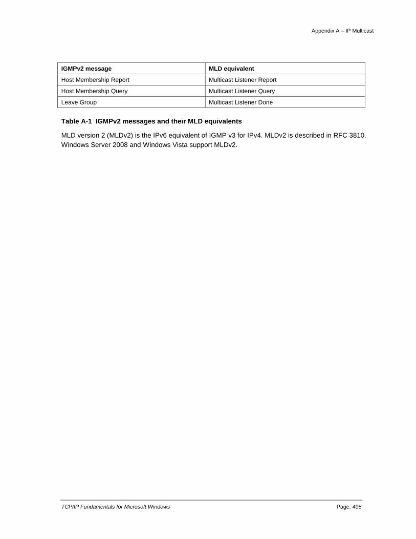
Appendix A – IP Multicast
TCP/IP Fundamentals for Microsoft Windows Page: 495
IGMPv2 message MLD equivalent
Host Membership Report Multicast Listener Report
Host Membership Query Multicast Listener Query
Leave Group Multicast Listener Done
Table A-1 IGMPv2 messages and their MLD equivalents
MLD version 2 (MLDv2) is the IPv6 equivalent of IGMP v3 for IPv4. MLDv2 is described in RFC 3810.
Windows Server 2008 and Windows Vista support MLDv2.

Appendix A – IP Multicast
TCP/IP Fundamentals for Microsoft Windows Page: 496
IPv4 Multicast Forwarding Support in Windows Server 2008 and Windows Server 2003
Multicast forwarding in Windows Server 2008 and Windows Server 2003 consists of the following:
IPv4 multicast forwarding by the Internet Protocol Version 4 (TCP/IPv4) or Internet Protocol (TCP/IP)
component
The IGMP routing protocol component of Routing and Remote Access
IPv4 Multicast Forwarding
In Windows, IPv4 multicast forwarding is supported by the Internet Protocol Version 4 (TCP/IPv4) or
Internet Protocol (TCP/IP) component. IPv4 multicast forwarding is enabled when you configure and
enable Routing and Remote Access. The Internet Protocol Version 4 (TCP/IPv4) or Internet Protocol
(TCP/IP) component maintains an IPv4 multicast forwarding table, which can be viewed from the
Routing and Remote Access snap-in or by using the netsh routing ip show mfe command.
Note The Internet Protocol Version 6 (TCP/IPv6) component in Windows Server 2008 and Windows Vista
supports IPv6 multicast forwarding, which you can enable with the netsh interface ipv6 set global
multicastforwarding=enable command. However, at the time of the publication of this book, there is no
mechanism to update the IPv6 multicast forwarding table.
IGMP Routing Protocol Component
Because there are no multicast routing protocols provided with Windows Server 2008 or Windows
Server 2003, the maintenance of entries in the IPv4 multicast forwarding table is a function of IGMP, a
component that is added as an IPv4 routing protocol.
To add the IGMP routing protocol component, do the following:
1. Click Start, click Control Panel, double-click Administrative Tools, and then double-click Routing
And Remote Access.
2. In the console tree, open Routing And Remote Access, the server name, and then either IPv4 or IP
Routing.
3. In the console tree, right-click General, and then click New Routing Protocol.
4. In the Select Routing Protocol dialog box, click IGMP Router And Proxy, and then click OK.
The IGMP routing protocol component might have already been added, depending on your choices in
the Routing and Remote Access Server Setup wizard.
Although the IGMP routing protocol component provides some limited ability to create or extend
multicast-enabled IPv4 networks, it is not the equivalent of a multicast routing protocol, such as DVMRP
or PIM. It is not recommended for use to create a multicast-enabled IPv4 network of an arbitrary size or
topology.
After the IGMP routing protocol is added, you must add router interfaces by doing the following:
1. In the console tree of the Routing and Remote Access snap-in, open Routing And Remote Access,
the server name, and then either IPv4 or IP Routing.

Appendix A – IP Multicast
TCP/IP Fundamentals for Microsoft Windows Page: 497
2. In the console tree, right-click IGMP, and then click New Interface.
3. In Interfaces, click the interface you want to enable, and then click OK.
4. On the General tab of the IGMP Properties dialog box for the interface, verify that the Enable IGMP
check box is selected.
5. Under Mode, click IGMP Router or IGMP Proxy. Under IGMP Protocol Version, select the version
of IGMP being used in your network.
6. Click OK.
Figure A-6 shows the General tab for the properties of an IGMP interface.
Figure A-6 The General tab for the properties of an IGMP interface
When you add an interface to the IGMP routing protocol component in the Routing and Remote Access
snap-in, you must configure the interface with one of the following:
IGMP router mode
IGMP proxy mode
IGMP Router Mode
When an IGMP routing protocol interface is configured in IGMP router mode, it performs the following
functions:
Listens in multicast promiscuous mode.
Listens for IGMP Host Membership Report messages and Leave Group messages.
Sends IGMP Host Membership Queries.
Maintains entries in the IPv4 multicast forwarding table.
IGMP router mode can be enabled on multiple interfaces. For each interface, a specific version of IGMP
can be configured. The default version is IGMP v3.

Appendix A – IP Multicast
TCP/IP Fundamentals for Microsoft Windows Page: 498
IGMP Proxy Mode
While the purpose of IGMP router mode is to act as a multicast router, the purpose of IGMP proxy
mode is to act as a multicast proxy for hosts on interfaces on which IGMP router mode is enabled.
When an IGMP routing protocol interface is configured in IGMP router mode, it performs the following
functions:
Forwards IGMP Host Membership Reports
All IGMP Host Membership Reports received on IGMP router mode interfaces are retransmitted on
the IGMP proxy mode interface.
Registers multicast MAC addresses
For shared access technologies such as Ethernet, the network adapter is left in unicast listening
mode. For each unique group registered by IGMP Host Membership Reports forwarded on the
IGMP proxy mode interface, the network adapter is programmed to pass up frames with the
corresponding multicast MAC address. Each additional multicast MAC address is an entry in the
table of interesting destination MAC addresses on the network adapter. Each network adapter has
a maximum number of entries it can store. If the maximum number of entries is used, then the
IGMP routing protocol enables multicast promiscuous listening mode on the network adapter.
Adds entries to the multicast forwarding table
When non-local multicast traffic is received on an IGMP router mode interface, the IGMP routing
protocol adds or updates an entry to the multicast forwarding table to forward the multicast traffic
out the IGMP proxy mode interface. The end result of this process is that any non-local multicast
traffic received on IGMP router mode interfaces is flooded, or copied, to the IGMP proxy mode
interface.
Receives multicast traffic received on IGMP proxy mode interfaces
Multicast traffic received on the IGMP proxy mode interface corresponding to the groups registered
by hosts on IGMP router mode interfaces are forwarded to the appropriate interfaces using the IP
protocol and the multicast forwarding table.
The purpose of IGMP proxy mode is to connect a Windows Server 2008 or Windows Server 2003
router to a multicast-enabled IPv4 network, such as the multicast backbone of the IPv4 Internet
(MBone), or a private intranet that is using multicast routing protocols, such as DVMRP and PIM. Figure
A-7 shows an example of using IGMP router mode and IGMP proxy mode to connect a small office
network to the MBone.

Appendix A – IP Multicast
TCP/IP Fundamentals for Microsoft Windows Page: 499
Figure A-7 Using IGMP proxy mode to connect a small office network to the MBone
The IGMP proxy mode interface acts like a host and joins host groups on behalf of hosts on its IGMP
router mode interfaces. Multicast traffic sent to host members on IGMP router mode interfaces are
received on the IGMP proxy mode interface and forwarded by the Internet Protocol Version 4
(TCP/IPv4) or Internet Protocol (TCP/IP) component. Multicast traffic sent by hosts on IGMP router
mode interfaces are flooded on the IGMP proxy mode interface where a downstream IPv4 multicast-
enabled router can either forward the traffic or ignore it.
IGMP proxy mode can only be enabled on a single IGMP routing protocol interface. The correct
interface on which to enable IGMP proxy mode is the interface attached to a subnet containing a
multicast router running multicast routing protocols. In other words, the IGMP proxy mode interface
"points" to the multicast-enabled intranet.

Appendix A – IP Multicast
TCP/IP Fundamentals for Microsoft Windows Page: 500
IPv4 Multicast Address Allocation with MADCAP
The Multicast Address Dynamic Client Allocation Protocol (MADCAP) is an Internet standard for
multicast address allocation defined in RFC 2730. The primary benefit of MADCAP is that you can use
it to leverage your existing Windows Dynamic Host Configuration Protocol (DHCP) infrastructure to
assign multicast IPv4 addresses in the same way that you assign unicast IPv4 addresses.
The multicast address allocation uses the following components:
MADCAP servers
MADCAP servers allocate IPv4 multicast addresses. For Windows, a MADCAP server is a
computer running Windows Server 2008 or Windows Server 2003 and the DHCP Server service.
Using the DHCP snap-in, you must configure and activate at least one multicast scope.
MADCAP clients
MADCAP clients use the MADCAP protocol to request IPv4 multicast addresses from a MADCAP
server. Windows supports a MADCAP application programming interface (API) so that an
application can use MADCAP to request, renew, or release a unique IPv4 multicast address from a
MADCAP server.
An example of a MADCAP client application is a video conferencing server service that uses MADCAP
to receive a unique multicast address and then communicate that address to connecting video clients.
After the initial connection negotiation, the video client computer listens on the IPv4 multicast address
for the video stream.
Using Multicast Scopes
A multicast scope is a range of IPv4 multicast addresses that the MADCAP server is configured to
assign to requesting MADCAP clients. When deciding the multicast address ranges to use for multicast
scopes on your MADCAP server, there are two ranges of addresses that are recommended:
Administratively scoped multicast addresses are in the 239.192.0.0/14 range (from 239.192.0.1 to
239.255.255.255) and are intended for use by an organization using multicast scopes privately for its
own internal use. Administratively scoped multicast addresses are described in detail in RFC 2365.
Globally scoped multicast addresses are in the range 233.0.0.0/8 (from 233.0.0.1 to 233.255.255.255)
and are intended for use by an organization using multicast scopes on the Internet. Within the
233.0.0.0/8 range, the second and third octets are used for the autonomous system (AS) number,
assigned to the organization by an Internet Assigned Numbers Authority (IANA) registry. The last octet
identifies the multicast group. For more information on AS numbering, see RFC 1930.
The Windows Server 2008 or Windows Server 2003 DHCP Server service supports both the DHCP and
MADCAP protocols. These protocols function separately and are not dependent on each other. To
configure a DHCP-only server, configure DHCP scopes but no multicast scopes. To configure a
MADCAP-only server, configure multicast scopes but no DHCP scopes.
To create a multicast scope on a computer running Windows Server 2008 or Windows Server 2003 and
the DHCP Server service, do the following:
1. Click Start, click Settings, click Control Panel, double-click Administrative Tools, and then double-

Appendix A – IP Multicast
TCP/IP Fundamentals for Microsoft Windows Page: 501
click DHCP.
2. In the console tree, click the applicable DHCP server.
3. On the Action menu, click New Multicast Scope.
4. Follow the instructions in the New Multicast Scope wizard.
The New Multicast Scope wizard guides you through the configuration of the multicast address range,
exclusions, lease duration, and scope activation.

Appendix A – IP Multicast
TCP/IP Fundamentals for Microsoft Windows Page: 502
Reliable Multicast with Pragmatic General Multicast (PGM)
Multicast data streams are typically sent using the User Datagram Protocol (UDP). Transmission
Control Protocol (TCP) is not used because it is designed for one-to-one unicast streams of data.
Multicast data streams sent over UDP are inherently unreliable because UDP does not provide
guaranteed delivery or retransmission of lost packets. Unless reliability is provided by the upper layer
protocol, lost packets in UDP-based multicast data streams cannot be detected or recovered.
The Reliable Multicast Transport working group of Internet Engineering Task Force (IETF) has created
a set of standards for the reliable transmission of multicast data streams from one or multiple senders
to multiple receivers. There are many protocol standards that provide reliable multicast at the transport
or application layers. Existing reliable multicast protocols fall into the following four categories:
1. Negative acknowledgement (NACK)-only
Receivers send NACK packets to request, from the sender, the retransmission of missing packets in
the multicast data stream. NACK-only protocols do not require any additional support from routers in
the network.
2. Tree-based acknowledgement (ACK)
Receivers send positive acknowledgments to indicate multicast data packets that are successfully
received.
3. Asynchronous Layered Coding (ALC)
Senders provide forward error correction (FEC) with no messages from receivers or the routers of the
network.
4. Router assist
Receivers send NACK packets. Routers in the network assist with retransmitting lost packets.
PGM Overview
PGM is a router assist type of reliable multicast protocol that is described in RFC 3208. PGM-enabled
receivers use NACK packets to request the retransmission of missing packets. PGM-enabled routers in
a network define a logical PGM topology and can facilitate the recovery of lost packets by sending them
on behalf of the sender. The PGM topology is overlaid on top of the physical IPv4 network topology.
PGM routers define a series of PGM hops between a sender and its receivers. Although defined in RFC
3208, PGM routers are not required. The PGM topology of a network can consist of the single logical
hop between the sender and the receivers.
PGM does not provide all of the capabilities of TCP for multicast data streams. For example, PGM does
not provide sender or receiver-side flow control, byte stream windowing, or congestion control. PGM
provides basic reliability for PGM-enabled applications.
PGM is a transport layer multicast protocol that runs directly over IPv4 using protocol number 113. It
does not use TCP or UDP for its own messages or for multicast data transmission. PGM is the only
reliable multicast protocol supported by Windows Server 2008, Windows Vista, and Windows Server
2003.

Appendix A – IP Multicast
TCP/IP Fundamentals for Microsoft Windows Page: 503
Adding and Using the Reliable Multicast Protocol
To use PGM on computers running Windows Server 2008, Windows Vista, or Windows Server 2003,
you must add the Reliable Multicast Protocol component and create PGM-enabled applications.
Adding the Reliable Multicast Protocol
To add the Reliable Multicast Protocol to a connection, complete the following steps:
1. From the Network Connections folder, right-click the connection, and then click Properties.
2. In the properties dialog box for the connection, click Install.
3. In Select Network Feature Type or Select Network Component Type, double-click Protocol.
4. In the Network Protocol list, click Reliable Multicast Protocol, and then click OK.
5. To save changes to the connection properties, click Close.
The Reliable Multicast Protocol component appears in the list of items being used by the connection,
but has no configurable properties.
Writing PGM-enabled Applications
To use PGM, an application must use Windows Sockets and the PGM socket options. A sender
application uses Windows Sockets to create a PGM socket, bind the socket to any address, and then
connect to the multicast group address. A receiver application uses Windows Sockets to create a PGM
socket, bind the socket to the multicast group address, post a listen on the new socket, and then use
the accept() function to obtain a socket handle for the PGM session.
Microsoft products that use PGM include Message Queuing (also known as MSMQ) and Automated
Deployment Services (ADS).
How PGM and the Reliable Multicast Protocol Works
A receiver uses the following process:
1. The multicast application opens a listen socket with the appropriate reliable multicast socket options.
2. The receiver sends an IGMP Host Membership Report message to inform the local routers of the
receiver's membership in the multicast group.
A sender uses the following process:
1. The multicast application opens a send socket with the appropriate reliable multicast socket options.
2. The multicast application begins to send data. PGM packets containing data are sent beginning with
a sequence number of 0, and are incremented by 1 for subsequent packets.
3. The multicast-enabled routers forward the multicast data packets throughout the IPv4 network to the
subnets that contain group members.
When a receiver determines that there is a missing packet, it sends a PGM message to its nearest
PGM router, requesting that the missing packet with a specific sequence number be resent. This
request is forwarded to either the original source or a PGM router that stores copies of recent packets
sent by the source. In either case, the missing packet is sent directly to the requesting receiver.

Appendix A – IP Multicast
TCP/IP Fundamentals for Microsoft Windows Page: 504

Appendix B – Simple Network Management Protocol
TCP/IP Fundamentals for Microsoft Windows Page: 505
Appendix B – Simple Network Management Protocol
Abstract
This appendix describes the Simple Network Management Protocol (SNMP) and its support in the Microsoft Windows
operating systems. SNMP is used in enterprise network environments to manage many types of network devices. A
network administrator must understand SNMP to integrate computers running Windows Vista, Windows XP, Windows
Server 2008, or Windows Server 2003 into an SNMP-managed environment.

Appendix B – Simple Network Management Protocol
TCP/IP Fundamentals for Microsoft Windows Page: 506
SNMP Overview
SNMP is a network management protocol and infrastructure widely used on IP networks. It was
originally developed in the Internet community to monitor and troubleshoot routers and bridges. SNMP
allows network administrators to manage network devices such as workstation or server computers,
routers, switches, and wireless access points.
SNMP can be used to:
Configure devices remotely You can use an SNMP to configure a device across the network from a
central management computer.
Monitor network performance You can use an SNMP to systematically and periodically query
devices for current performance statistics to monitor network throughput.
Detect network faults or inappropriate access A device can use SNMP to send a message when
specific events occur. Common types of conditions to report to a management system include a device
being shut down and restarted, a link failure being detected on a router, inappropriate access, and low
disk space on a file server.
SNMP uses a distributed architecture consisting of the following components:
SNMP management systems
The SNMP management system, also known as a management station or a management console,
is a computer running SNMP management software that sends information and update requests to
devices running an SNMP agent.
The SNMP management system requests information from a device, such as the amount of hard
disk space available or the number of active sessions. If the management system has been granted
write access to a device, the management system can also change a device's configuration.
SNMP agents
An SNMP agent is a device running software that collects information and responds to
management system requests for information. The SNMP agent software can be configured to
determine which statistics are tracked and which management systems are authorized to request
information. Typically, agents do not originate messages, but only respond to them. The exception
is when the agent is configured to report a specific event, such as a system restart or an
inappropriate access.
Figure B-1 shows an example of SNMP being used on a network.

Appendix B – Simple Network Management Protocol
TCP/IP Fundamentals for Microsoft Windows Page: 507
Figure B-1 An example of SNMP being used on a network
SNMP is defined in RFC 1157.
The Management Information Base
The information that an agent can collect and a management system can request from an agent is
contained in a Management Information Base (MIB). A MIB is a set of manageable objects representing
various types of information about a network device, such as the number of active sessions or the
version of network operating system software that is running on a host. SNMP management systems
and agents share a common understanding of MIB objects. For a given MIB, the agent maintains
information about the objects in the MIB and the management system retrieves the information in the
MIB from the agent.
The Hierarchical Name Tree
The name space for MIB objects is hierarchical. It is structured so that each manageable object can be
assigned a globally unique name. When a management system requests a data object from an agent, it
includes the globally unique name in the request. Authority for parts of the name space is assigned to
individual organizations. This allows organizations to assign names to new objects without consulting
an Internet authority for each assignment. For example, the name space assigned to the LAN Manager
MIB II is 1.3.6.1.4.1.77. LAN Manager is an obsolete Microsoft operating system. Microsoft has also
been assigned 1.3.6.1.4.1.311, and all new MIBs for Microsoft-specific technologies are created under
that branch. Microsoft has the authority to assign names to objects anywhere below that portion of the
name space.
Figure B-2 shows a portion of the SNMP hierarchical name tree.
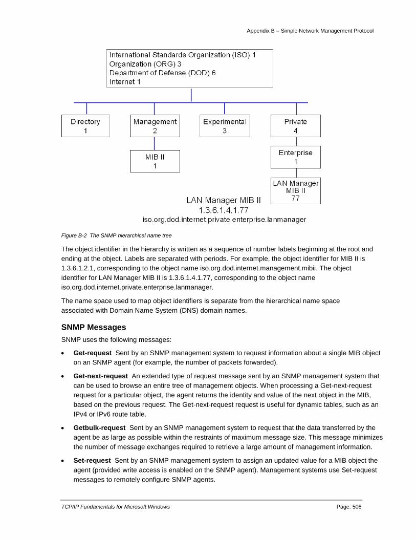
Appendix B – Simple Network Management Protocol
TCP/IP Fundamentals for Microsoft Windows Page: 508
Figure B-2 The SNMP hierarchical name tree
The object identifier in the hierarchy is written as a sequence of number labels beginning at the root and
ending at the object. Labels are separated with periods. For example, the object identifier for MIB II is
1.3.6.1.2.1, corresponding to the object name iso.org.dod.internet.management.mibii. The object
identifier for LAN Manager MIB II is 1.3.6.1.4.1.77, corresponding to the object name
iso.org.dod.internet.private.enterprise.lanmanager.
The name space used to map object identifiers is separate from the hierarchical name space
associated with Domain Name System (DNS) domain names.
SNMP Messages
SNMP uses the following messages:
Get-request Sent by an SNMP management system to request information about a single MIB object
on an SNMP agent (for example, the number of packets forwarded).
Get-next-request An extended type of request message sent by an SNMP management system that
can be used to browse an entire tree of management objects. When processing a Get-next-request
request for a particular object, the agent returns the identity and value of the next object in the MIB,
based on the previous request. The Get-next-request request is useful for dynamic tables, such as an
IPv4 or IPv6 route table.
Getbulk-request Sent by an SNMP management system to request that the data transferred by the
agent be as large as possible within the restraints of maximum message size. This message minimizes
the number of message exchanges required to retrieve a large amount of management information.
Set-request Sent by an SNMP management system to assign an updated value for a MIB object the
agent (provided write access is enabled on the SNMP agent). Management systems use Set-request
messages to remotely configure SNMP agents.

Appendix B – Simple Network Management Protocol
TCP/IP Fundamentals for Microsoft Windows Page: 509
Get-response Sent by the SNMP agent in response to a Get-request, Get-next-request, Getbulk-
request, or Set-request message.
Trap An unsolicited message sent by an SNMP agent to an SNMP management system when the
agent detects that a certain type of event has occurred. The SNMP management system that receives
a trap message is known as a trap destination. For example, a trap message might be sent when a
device is restarted.
The Get-request, Get-next-request, Getbulk-request, and Set-request messages are sent by a
management system to an agent as a unicast UDP message sent to the IPv4 address of the agent and
destination UDP port 161. An agent sends the Trap message to a management system as a unicast
UDP message sent to the IPv4 address of the management system and destination UDP port 162.
Figure B-3 shows the exchange of messages between an SNMP management system and an SNMP
agent.
Figure B-3 The exchange of messages between an SNMP management system and an SNMP agent
All SNMP messages are sent without data protection. To protect SNMP messages, use Internet
Protocol security (IPsec) to protect traffic between SNMP management systems and agents. Both the
management system and the agent must support IPsec. For more information about IPsec, see
Chapter 13, "Internet Protocol Security (IPsec) and Packet Filtering."
SNMP Communities
Management systems and agents belong to an SNMP community, which is a collection of hosts
grouped together for administrative purposes. The use of a community name provides context checking
for agents that receive requests and initiate traps, and for management systems that initiate requests
and receive traps. An agent will not accept a request from a management system outside its configured
communities. A management system will not accept a trap from an agent outside its configured
communities.
You use community names primarily as an element for organization, not security. SNMP messages are
typically sent without IPsec protection. By capturing unprotected SNMP messages, a malicious user
can determine the SNMP community name and send their own SNMP messages with the correct
community name.
There is no relationship between community names and domain or workgroup names. Community
names represent a named context for groups of the components of SNMP infrastructure.

Appendix B – Simple Network Management Protocol
TCP/IP Fundamentals for Microsoft Windows Page: 510
Agents and management systems can be members of multiple communities at the same time, allowing
for flexibility in configuring the administrative elements of your SNMP infrastructure.
Figure B-4 shows an example of two defined communities—IT and Admin.
Figure B-4 An example of SNMP communities
Only the agents and management systems that are members of the same community can communicate
with each other. For example:
Agent1 can receive and send messages to Manager2 because they are both members of the Admin
community.
Agent2, Agent3, and Agent4 can receive and send messages to Manager1 because they are all
members of the IT community.
The default name for many SNMP agents is Public. The SNMP service for Windows Server 2008,
Windows Vista, and Windows Server 2003 does not have a configured SNMP community name. The
SNMP service for Windows XP uses the default name of Public.
How SNMP Works
The following steps describe how SNMP works in a typical get operation:
1. An SNMP management system sends a request to an SNMP agent.
The request is a Get-request, Get-next-request, or Getbulk-request message with one or more data
objects and a community name, and is sent to the SNMP agent's IPv4 address and destination UDP
port 161. For example, the SNMP management system sends a Get-request message with the
community name IT requesting the number of active sessions.
2. The SNMP agent receives the SNMP message.

Appendix B – Simple Network Management Protocol
TCP/IP Fundamentals for Microsoft Windows Page: 511
The community name is verified. If the community name is invalid or the packet is malformed, it is
silently discarded. If the community name is valid, the request is passed to the appropriate MIB
component. The MIB component returns the requested information to the agent. For this example,
the SNMP agent retrieves the number of active sessions from the MIB.
3. The SNMP agent sends a Get-response message to the SNMP management system with the
requested information.
For this example, the SNMP agent sends a Get-response message with the community name IT that
contains the number of active sessions.
Figure B-5 shows this process.
Figure B-5 An example of how SNMP works

Appendix B – Simple Network Management Protocol
TCP/IP Fundamentals for Microsoft Windows Page: 512
Windows SNMP Service
The SNMP service in Windows is SNMP agent software that provides information to management
systems running SNMP management software. The SNMP service:
Responds to requests for status information from multiple hosts.
Reports significant events (traps) to multiple hosts as they occur.
Uses host names and IPv4 addresses to identify the hosts to which it reports information and from
which it receives requests.
The Windows SNMP service is a Windows Sockets application. It provides an internal infrastructure
that allows third-party software and hardware developers to create their own MIBs for use with the
Windows SNMP service and for the development of SNMP management system applications.
The SNMP service in Windows Server 2008 and Windows Server 2003 supports the following MIBs:
Internet MIB II
Internet MIB II is a superset of the previous standard, Internet MIB I. Internet MIB II defines objects
essential for either fault or configuration analysis. Internet MIB II is defined in RFC 1212.
LAN Manager MIB II
LAN Manager MIB II defines objects for share, session, user, and logon information. Most LAN
Manager MIB II objects have read-only access because typically SNMP messages are not
protected.
DHCP MIB
The Dynamic Host Configuration Protocol (DHCP) MIB defines objects to monitor DHCP server
activity. This MIB is automatically installed when the DHCP server service is installed. It contains
objects for monitoring DHCP, such as the number of DHCPDiscover messages received and the
number of addresses leased out to DHCP clients.
WINS MIB
The Windows Internet Name Service (WINS) MIB defines objects to monitor WINS server activity.
This MIB is automatically installed when the WINS Server service is installed. It contains objects for
monitoring WINS, such as the number of resolution requests successfully processed, the number of
resolution requests that failed, and the date and time of the last database replication.
IIS MIBs
The Internet Information Services (IIS) MIBs define objects to monitor File Transfer Protocol (FTP)
and Hypertext Transfer Protocol (HTTP) activity. These MIBs are automatically installed when IIS is
installed. They contain objects for monitoring the FTP and Web services of IIS and include counters
for total bytes sent and total files sent.
RADIUS Server MIBs
The Remote Authentication Dial-In User Service (RADIUS) Server MIBs define objects to monitor
RADIUS server authentication and accounting activity. These MIBs are automatically installed when
the Internet Authentication Service (IAS) is installed. They contain objects for monitoring the

Appendix B – Simple Network Management Protocol
TCP/IP Fundamentals for Microsoft Windows Page: 513
RADIUS server, such as the number of authentication requests successfully processed and the
number of accounting requests.
The RADIUS Authentication Server MIB is defined in RFC 2619. The RADIUS Accounting Server
MIB is defined in RFC 2621.
Installing and Configuring the SNMP Service
To install the SNMP service in Windows Vista, do the following:
1. From Control Panel-Programs and Features, click Turn Windows features on or off.
2. In Windows Features, click SNMP feature, and then click OK.
To install the SNMP service in Windows Server 2008, use the Server Manager snap-in to add the
SNMP Service feature.
To install the SNMP service in Windows Server 2003 and Windows XP, do the following:
3. Click Start, click Control Panel, double-click Add Or Remove Programs, and then click
Add/Remove Windows Components.
4. In Components, click Management And Monitoring Tools (but do not select or clear its check
box), and then click Details.
5. Select the Simple Network Management Protocol check box, and click OK.
6. Click Next.
The SNMP service starts automatically after installation.
Unlike many services in Windows, the SNMP service does not have a corresponding snap-in. Instead,
you configure the SNMP service through additional tabs on the properties of the SNMP service in the
Services snap-in.
To configure the SNMP service, do the following:
1. Click Start, click Control Panel, double-click Administrative Tools, and then double-click
Computer Management.
2. In the console tree, open Services And Applications, and then click Services.
3. In the details pane, right-click SNMP Service, and then click Properties.
You configure the SNMP service from the following tabs:
Agent
Traps
Security
Agent Tab
On the Agent tab, you can configure a contact person, the physical location of the computer, and
enable and disable the types of information that you want the SNMP service to collect. By default the
Applications, Internet, and End-to-end categories are enabled.
Figure B-6 shows the Agent tab.

Appendix B – Simple Network Management Protocol
TCP/IP Fundamentals for Microsoft Windows Page: 514
Figure B-6 The Agent tab for the SNMP service
Traps Tab
On the Traps tab, you configure the community name that is included in Trap messages and the trap
destinations—a list of IPv4 addresses to which Trap messages are sent.
Figure B-7 shows the Traps tab.
Figure B-7 The Traps tab for the SNMP service
Security Tab
On the Security tab, you configure the following:
Whether the SNMP service will send a trap to all trap destinations if it receives a request that does not
contain a recognized community name.

Appendix B – Simple Network Management Protocol
TCP/IP Fundamentals for Microsoft Windows Page: 515
The list of accepted community names.
Whether to accept SNMP messages from any host, or from a list of hosts by IPv4 address or host
name.
Figure B-8 shows the Security tab.
Figure B-8 The Security tab for the SNMP service
Evntcmd Tool
You can use the Evntcmd.exe tool at a command prompt to configure SNMP traps based on events
recorded in system logs. You can also use Evntcmd.exe to specify where trap messages are sent
within an SNMP community.

Appendix B – Simple Network Management Protocol
TCP/IP Fundamentals for Microsoft Windows Page: 516

Appendix C – Computer Browser Service
TCP/IP Fundamentals for Microsoft Windows Page: 517
Appendix C – Computer Browser Service
Abstract
This appendix describes how the Computer Browser service on computers running Microsoft Windows operating
systems works to display the list of workgroups and domains and the servers within them for the contents of the
Network and Microsoft Windows Network windows and related windows in My Network Places. A network
administrator must understand how the Computer Browser service works over an IPv4 network to determine why some
domains, workgroups, or the server computers within them are not displayed.

Appendix C – Computer Browser Service
TCP/IP Fundamentals for Microsoft Windows Page: 518
Computer Browsing Overview
The Computer Browser service in Windows maintains an updated list of domains, workgroups, and
server computers on the network and supplies this list to client computers upon request.
A domain is a grouping of computers that provide a centralized account database and security. The
definition of domain for computer browsing is separate from its definition for Active Directory. In Active
Directory, a domain is a collection of computer, user, and group objects defined by the administrator.
These objects share a common directory database, security policies, and security relationships with
other domains.
A workgroup is a logical grouping of computers that helps users locate shared resources such folders
and printers. Workgroups do not offer the centralized user accounts and security offered by domains. A
LAN group is either a domain or a workgroup.
The Computer Browser service maintains a distributed series of lists of available network resources as
viewed from the following locations:
Using the new Windows XP-style Start menu, click Start, and then click My Network Places. In the My
Network Places window, click Entire Network. In the Entire Network window, double-click Microsoft
Windows Network.
Using the classic Windows Start menu, double-click My Network Places on your desktop. In the My
Network Places window, double-click Entire Network. In the Entire Network window, double-click
Microsoft Windows Network.
For either method, the Microsoft Windows Network window displays a list of LAN groups.
The list of LAN groups and the servers within them are distributed to automatically elected browse
server computers. Computers elected as browse servers eliminate the need for all computers to
maintain a list of all the LAN groups and their servers on the network and lowers the amount of network
traffic required to build and maintain a list of all the computers on the network.
The browse list, the list of LAN groups and the servers within them that are accumulated and distributed
by the Computer Browser service, is separate from the list of computers maintained in Active Directory.
For example, when you click Search Active Directory in the Network Tasks pane of the My Network
Places window, the Find Users, Contacts, And Groups dialog box is displayed. Queries using this
dialog box are performed against Active Directory, not against the browse list maintained by computers
running the Computer Browser service.
The Computer Browser service operates by exchanging a set of NetBIOS over TCP/IP (NetBT)
broadcast and unicast messages. There is no support for computer browsing over IPv6. If NetBT is
disabled, the Computer Browser service can no longer operate. This means that for a network that has
NetBT disabled and is just using the Domain Name System (DNS) and Active Directory, you cannot
view any LAN groups or servers using the Entire Network window. You must use find computers using
Active Directory.
Computer browsing over remote access connections is aided by the NetBT proxy in Windows Server
2008 and Windows Server 2003, which is enabled by default for Routing and Remote Access on all
interfaces that are not connected to the Internet.

Appendix C – Computer Browser Service
TCP/IP Fundamentals for Microsoft Windows Page: 519
For more information about NetBT, see Chapter 11, "NetBIOS over TCP/IP" and Chapter 12 "Windows
Internet Name Service Overview."
The Computer Browser service in Windows performs three processes:
Collection of browsing information
Distribution of browsing information
Servicing of browse client requests
Browsing Collection and Distribution
The browsing collection and distribution processes occur between designated browse server
computers. The following types of browse servers are defined:
Master Browse Server
A computer that collects and maintains the browse list of available servers within its LAN group and
a list of other LAN groups and their Master Browse Servers. It also distributes the browse list to the
Backup Browse Servers.
Backup Browse Server
A computer that receives a copy of the browse list from the Master Browse Server, and distributes
information in the browse list to browse clients upon request.
Domain Master Browse Server
The first domain controller to register the NetBIOS name of Domain[1B] becomes the Domain
Master Browse Server. Besides being a Master Browse Server for its domain, the Domain Master
Browse Server synchronizes the browse list for the Master Browse Servers in the domain that are
located on remote subnets.
Computers are designated the Master Browse Server or a Backup Browse Server through an automatic
election process. For a given LAN group, there is only one Master Browse Server and zero or more
Backup Browse Servers. The number of Backup Browse Servers depends on the number of servers in
the LAN group.
Computers running Windows XP can perform the Master Browse Server and Backup Browse Server
roles. Only a computer running Windows Server 2008 or Windows Server 2003 that is acting as a
domain controller can perform the Domain Master Browse Server role.
The Collection Process
The Master Browse Server performs the collection process by accumulating the following information in
its browse list:
A list of servers within its LAN group
Periodically, every computer running the Server service within the LAN group broadcasts a Host
Announcement packet to the NetBIOS name LANGroup[1D]. The Server service corresponds to the
File and Printer Sharing for Microsoft Networks component in Network Connections and provides
file and print sharing using the Common Internet File System (CIFS), also known as the Server

Appendix C – Computer Browser Service
TCP/IP Fundamentals for Microsoft Windows Page: 520
Message Block (SMB) protocol. The Master Browse Server processes the Host Announcement
packet and adds or refreshes the sender’s computer name in the list of servers of the LAN group.
A list of other LAN groups
Periodically, every Master Browse Server of a LAN group broadcasts a Domain Announcement or
Workgroup Announcement packet to the NetBIOS name [01][02]__MSBROWSE__[01][02].
Contained in the Domain Announcement or Workgroup Announcement packet is the LAN group
name and the computer name of the Master Browse Server. Each Master Browse Server stores the
announced LAN group name and its associated Master Browse Server in the browse list.
The Distribution Process
The Master Browse Server distributes the browse list to the Backup Browse server computers that will
service the requests from browse clients. This occurs through the following:
Local Master Announcement packet
Periodically, the Master Browse Server broadcasts a Local Master Announcement packet to the
NetBIOS name LANGroup[1E]. This packet informs the Backup Browse Servers that a Master
Browse Server for the LAN group still exists. If the Master Browse Server does not periodically sent
a Local Master Announcement packet, a Backup Browse Server starts an election by broadcasting
an Election packet to the NetBIOS name LANGroup[1E]. The election process selects a new
Master Browse Server.
Browse list pull operation from Master Browse Server to Backup Browse Server
Periodically, each Backup Browse Server contacts the Master Browse Server in its LAN group to
download the browse list. The downloaded browse list includes the list of servers within the LAN
group and the list of other LAN groups and their associated Master Browse Servers.
Figure C-1 shows the collection and distribution process.
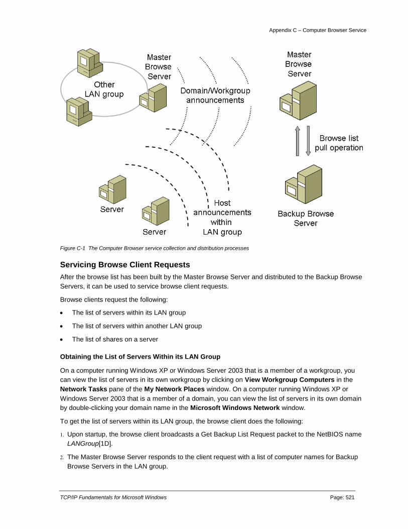
Appendix C – Computer Browser Service
TCP/IP Fundamentals for Microsoft Windows Page: 521
Figure C-1 The Computer Browser service collection and distribution processes
Servicing Browse Client Requests
After the browse list has been built by the Master Browse Server and distributed to the Backup Browse
Servers, it can be used to service browse client requests.
Browse clients request the following:
The list of servers within its LAN group
The list of servers within another LAN group
The list of shares on a server
Obtaining the List of Servers Within its LAN Group
On a computer running Windows XP or Windows Server 2003 that is a member of a workgroup, you
can view the list of servers in its own workgroup by clicking on View Workgroup Computers in the
Network Tasks pane of the My Network Places window. On a computer running Windows XP or
Windows Server 2003 that is a member of a domain, you can view the list of servers in its own domain
by double-clicking your domain name in the Microsoft Windows Network window.
To get the list of servers within its LAN group, the browse client does the following:
1. Upon startup, the browse client broadcasts a Get Backup List Request packet to the NetBIOS name
LANGroup[1D].
2. The Master Browse Server responds to the client request with a list of computer names for Backup
Browse Servers in the LAN group.

Appendix C – Computer Browser Service
TCP/IP Fundamentals for Microsoft Windows Page: 522
3. The client randomly selects one of the Backup Browse Servers. When the user wants to view the list
of servers in its LAN group, the computer sends the selected Backup Browse Server a request for the
servers in its LAN group.
4. The Backup Browse Server responds with the list of servers in the LAN group.
Figure C-2 shows this process.
Figure C-2 Servicing browse client requests
For subsequent requests for a list of servers within its LAN group, the client continues to use the list of
Backup Browse Server names obtained during startup and does not broadcast a new Get Backup List
Request packet. The success of the browse client request is dependent on the client getting a response
from the Master Browse Server and the client’s ability to resolve the computer name of the randomly
selected Backup Browse Server to its IPv4 address.
Obtaining the List of Servers Within Another LAN Group
On a computer running Windows XP or Windows Server 2003 that is a member of a workgroup, you
can view the list of servers in another LAN group by clicking on the LAN group name in the Browse For
Folder dialog box. On a computer running Windows XP or Windows Server 2003 that is a member of a
domain, you can view the list of servers in another LAN group by double-clicking the LAN group name
in the Microsoft Windows Network window.
To get the list of servers within another LAN group, the client broadcasts a Get Backup List Request
packet to the NetBIOS name LANGroup[1D]. The Master Browse Server for that LAN group responds
Appendix C – Computer Browser Service
TCP/IP Fundamentals for Microsoft Windows Page: 523
to the client request with a list of computer names for Backup Browse Servers within the LAN group.
The client then randomly selects one of the Backup Browse Servers and sends it a request to download
the list of servers in the LAN group. The response from the selected Backup Browse Server contains
the list of servers in the LAN group.
The success of this operation depends on the client getting a response from the Master Browse Server
for the LAN group and the client’s ability to resolve the computer name of the randomly selected
Backup Browse Server of the LAN group to an IPv4 address.
Obtaining the List of Shares on a Server
On a computer running Windows XP or Windows Server 2003, you can view the list of shares on a
selected server by double-clicking the computer in the LAN group window. Alternately, you can view the
list of shares of a specific computer from the display of the net view \\servername command.
To get the list of shares on a server, the client computer attempts to resolve the NetBIOS name for the
Server service on the desired computer, which corresponds to ComputerName[20]. After the name is
resolved, a TCP session, a NetBIOS session, and an SMB session are created between the browse
client and the file sharing server. After the SMB session is created, the client requests a list of shares.
Although the request for the list of servers does not involve the Computer Browser service or browse
servers, it is part of the browsing operation done through My Network Places.
The success of this client request is dependent on the client’s ability to resolve the computer name of
the selected computer to its IPv4 address and to establish an authenticated SMB session with the
server.
The Computer Browser Service on Computers Running Windows Server 2008
Windows Server 2008 sets the startup state of the Computer Browser service to disabled by default for
a new installation of Windows Server and when upgrading an existing server to Windows Server 2008.
The default startup state of the Computer Browser service on computers running Windows Server 2008
can cause problems for a domain controller in the primary domain controller flexible single master
operations (PDC FSMO) role. For computer browsing, the computer in the PDC FSMO role centrally
collects and distributes information about domains, workgroups, and computers for multi-subnet
networks. If the computer in the PDC FSMO role is not running the Computer Browser service,
computer browse lists across the network will contain only domains, workgroups, and computers on the
local subnet.
To prevent this problem, configure the startup type for the Computer Browser service for Automatic on
the computer in the PDC FSMO role and then start Computer Browser service. You can do this from
the Services snap-in or at an elevated command prompt with the following commands:
sc config browser start= auto
sc start browser
Because the Computer Browser service relies on the file and printer sharing, you will also need to turn
on File and Printer Sharing in the Network and Sharing Center. Alternatively, move the PDC FSMO role
to another domain controller that has the Computer Browser service started and configured for
automatic startup and File and Printer Sharing turned on in the Network and Sharing Center.

Appendix C – Computer Browser Service
TCP/IP Fundamentals for Microsoft Windows Page: 524
Additionally, if the only server computer on a subnet is running Windows Server 2008, client computers
will become the local browse server on the subnets. As client computers are started and are shut down,
the role of the local browse server will pass from one client computer to another, possibly resulting in an
inconsistent display of domains, workgroups, and computers. To prevent this problem, on the computer
running Windows Server 2008, turn on file and printer sharing, configure the startup type for the
Computer Browser service for Automatic, and then start the Computer Browser service.

Appendix C – Computer Browser Service
TCP/IP Fundamentals for Microsoft Windows Page: 525
Computer Browser Service Operation on an IPv4 Network
Because the Computer Browser service relies on a series of broadcast NetBIOS over TCP/IP packets,
the placement of IPv4 routers can create problems. IPv4 routers do not forward broadcast packets. To
facilitate client browsing of all network resources in an IPv4 network, there must be mechanisms for the
collection, distribution, and servicing of client requests for browse lists when servers, browse servers,
and browse clients are located on different subnets.
The browsing collection, distribution, and the servicing of client requests across IPv4 routers must now
take place using a combination of unicast and broadcast IPv4 traffic, rather than just broadcast IPv4
traffic. To facilitate computer browsing across an IPv4 network, the Computer Browser services uses
the following:
Windows Internet Name Service (WINS) WINS helps in the collection of browse lists and the
servicing of client requests.
Entries in the Lmhosts file Special entries in the Lmhosts file help facilitate the distribution of
browsing information and the servicing of client requests.
Note The Computer Browser service relies on media access control (MAC)-level broadcast packets sent
using NetBT to and from UDP port 138 (the NetBIOS datagram port). In contrast, B-node NetBIOS name
registration and name query requests are sent as MAC-level broadcasts over UDP port 137 (the NetBIOS
name service port). Some routers can be configured to forward NetBIOS broadcasts from one IPv4 subnet
to another. If the IPv4 router is configured to forward NetBIOS broadcasts, the Computer Browsing service
works as if all the LAN groups were located on the same subnet. All Master Browse Servers are aware of all
servers in their LAN group and all other LAN groups and all browse client requests can be satisfied.
If NetBIOS broadcast forwarding is enabled on all IPv4 routers in the network, the following sections do not
apply. However, this solution is highly discouraged because it increases the amount of broadcast traffic on
each subnet, leading to decreased performance by all nodes on the network. Enabling broadcast forwarding
can also cause browse server election conflicts.
The following sections examine how the Computer Browser service works across an IPv4 network for
these browsing situations:
Domain spanning an IPv4 router
Multiple domains separated by IPv4 routers
Workgroup spanning an IPv4 router
Multiple workgroups separated by IPv4 routers
Domain Spanning an IPv4 Router
Figure C-3 shows a domain that spans an IPv4 router. There are domain members on at least two
different subnets located across an IPv4 router.

Appendix C – Computer Browser Service
TCP/IP Fundamentals for Microsoft Windows Page: 526
Figure C-3 A domain that spans an IPv4 router
For this configuration, the following sections examine:
The collection and distribution process
The servicing of browse client requests
Collection and Distribution Process
When using domains that are split across routers, browse server elections occur within each subnet
and each subnet functions as an independent browsing entity with its own Master Browse Server and
Backup Browse Servers.
Each Master Browse Server collects the following for its own subnet:
The list of servers within its domain, by listening for Host Announcement packets sent by computers in
its domain.
The list of other LAN groups and their corresponding Master Browse Servers, by listening for Domain
Announcement or Workgroup Announcement packets sent by the Master Browse Servers of other LAN
groups.
If all the servers in the domain existed on one subnet, the Domain Master Browse Server would also be
the Master Browse Server for the domain. In the configuration in Figure C-3, the Domain Master
Browse Server is attached to only one subnet. To facilitate the flow of information for the browse list
across the IPv4 router, the Master Browse Servers on the other subnets must communicate with the

Appendix C – Computer Browser Service
TCP/IP Fundamentals for Microsoft Windows Page: 527
Domain Master Browse Server. The communication between the Domain Master Browse Server and
Master Browse Servers takes two forms:
Master Browse Servers update the Domain Master Browse Server with their collected list of servers in
the domain and other LAN groups on its subnet.
Master Browse Servers download the Domain Master Browse Server's browse list, which contains all of
the server names within the domain and all other LAN group names collected by the Domain Master
Browse Server and all other Master Browse Servers on other subnets.
The result is that each Master Browse Server gets the Domain Master Browse Server's browse list. The
Backup Browse Servers on each subnet download the browse list from their local Master Browse
Server.
The communication between the Master Browse Server and Domain Master Browse Server occurs
periodically through unicast IPv4 traffic. The Master Browse Server for each subnet contacts the
Domain Master Browse Server to exchange information. The Master Browse Server resolves the IPv4
address of the Domain Master Browse Server using either:
WINS If the Master Browse Server is a WINS client, it will query its WINS servers for the NetBIOS
name Domain[1B]. Only the Domain Master Browse Server registers this NetBIOS name.
Lmhosts file The Master Browse Server can use special entries in the Lmhosts file to locate the
Domain Master Browse Server. The details of these entries are discussed in the “Configuring the
Lmhosts File for an Domain that Spans IPv4 Routers” section of this chapter.
Servicing Browse Client Requests
When servicing browse client requests, the browse client can request the following:
List of servers within its domain or a LAN group on its subnet
To get the list of servers within its domain or for a LAN group on its subnet, the browse client
initially broadcasts a Get Backup List Request packet to the NetBIOS name LANGroup[1D]. The
Master Browse Server for the LAN group on the browse client’s subnet responds to the browse
client request with a list of computer names for Backup Browse Servers. The browse client then
randomly selects one of the Backup Browse Servers and contacts it directly for a list of servers
within the LAN group.
List of servers within another LAN group on another subnet
This process is described in the “Multiple Domains Across IPv4 Routers” section of this chapter.
List of shares on a server
To get the list of shares on a server, the browse client attempts to resolve the NetBIOS name for
the Server service on the desired computer, which corresponds to ComputerName[20]. Once the
name is resolved, a TCP session, a NetBIOS session, and an SMB session are created between
the browse client and the desired server. The list of shares on the server computer is sent over the
SMB session.

Appendix C – Computer Browser Service
TCP/IP Fundamentals for Microsoft Windows Page: 528
Configuring the Lmhosts File for an Domain that Spans IPv4 Routers
To enable direct communication between Master Browse Servers on remote subnets and the Domain
Master Browse Server for computers that are not enabled to use WINS, you must configure the
Lmhosts file with the NetBIOS names and IPv4 addresses of the browse server computers.
The Lmhosts file on each subnet’s Master Browse Server should contain a series of entries for all the
domain controllers of the domain. Each entry must have the following information:
The IPv4 address and computer name of the domain controller
The domain name preceded by the #PRE #DOM: tags
The following is an example entry:
131.107.7.80 DC100 #PRE #DOM:EXAMPLE
For this Lmhosts entry, a domain controller for the EXAMPLE domain is a computer named DC100 at
the IPv4 address of 131.107.7.80. By adding entries for all the domain controllers, regardless of which
domain controller becomes the Domain Master Browse Server, the Lmhosts files do not need to be
changed on the other Master Browse Server computers.
When multiple Lmhosts entries exist for the same domain name, a computer running Windows XP or
Windows Server 2003 acting as a Master Browse Server determines which of the entries corresponds
to the Domain Master Browse Server by sending a query to each the IPv4 address. Only the Domain
Master Browse Server responds to the query. The computer then contacts the Domain Master Browse
Server to exchange browse list information.
At each domain controller, the Lmhosts file must be configured with entries for each of the Master
Browse Servers on remote subnets. By default, the Master Browse Server computer is elected using a
set of election criteria. To ensure that a specific computer is elected the Master Browse Server, set the
registry value
HKEY_LOCAL_MACHINE\System\CurrentControlSet\Services\Browser\Parameters\IsDomainMaster to
TRUE (REG_SZ). A computer with IsDomainMaster set to TRUE will typically only lose an election to
the Domain Master Browse Server or other computers with IsDomainMaster set to TRUE.
After you have configured the IsDomainMaster registry value on a designated server computer on each
subnet, add entries to the Lmhosts file on each domain controller for each of the designated Master
Browse Servers. These entries allow the Domain Master Browse Server to determine the set of
computers to contact to distribute the Domain Master Browse Server's browse list.
Multiple Domains Separated By IPv4 Routers
Figure C-4 shows multiple domains that are separated by an IPv4 router.

Appendix C – Computer Browser Service
TCP/IP Fundamentals for Microsoft Windows Page: 529
Figure C-4 Multiple domains separated by an IPv4 router
For this configuration, the following sections examine:
Collection and distribution process
Servicing browse client requests
Collection and Distribution Process
Besides collecting the servers in its domain, a Master Browse Server collects the names of other LAN
groups on its subnet. All of this information is sent to the Domain Master Browse Server and distributed
to the other Master Browse Servers for that domain. Browse clients within that domain see the list of all
of the LAN groups that have been collected.
One enhancement WINS adds to the mechanism of collecting LAN group names is that a WINS-
enabled Domain Master Browse Server periodically queries the WINS server to obtain a list of all of the
domains from the WINS database. The Domain Master Browse Server queries WINS for all the
NetBIOS names that end with the 0x1B character. All NetBIOS names of this type are NetBIOS domain
names that were registered by Domain Master Browse Servers.
The list of domains obtained through the WINS query only contains the domain names and their
corresponding IP addresses. The list does not include the names of the Domain Master Browse
Servers that registered those names. To obtain the Domain Master Browse Server for the domain, the
Domain Master Browse Server computer sends a NetBIOS Adapter Status message to each IPv4
address corresponding to the NetBIOS computer name Domain[1B] for each domain collected through
the WINS query. The response to the NetBIOS Adapter Status message contains the computer name
Appendix C – Computer Browser Service
TCP/IP Fundamentals for Microsoft Windows Page: 530
of the computer that registered the domain name. In this way, the Domain Master Browse Server
completes its list of domain names and their corresponding Domain Master Browse Servers.
The advantage of this process is that the Domain Master Browse Server for any domain now has a list
of all domains (for those Domain Master Browse Servers that are WINS clients or have static WINS
entries), including those on remote subnets that are not spanned by its domain.
Servicing WINS-enabled Client Requests for Remote Domains
When a client requests a list of servers from a domain other than its own, the process for resolving the
Master Browse Server for the domain depends on the client type. For WINS clients, the client
broadcasts a Get Backup List Request packet to the NetBIOS name LANGroup[1D] to get a list of
Backup Browse Servers from a local Master Browse Server. Because the browse client is requesting a
set of Backup Browse Servers for a remote domain, it will not receive a response to the broadcasted
Get Backup List Request packet.
The client then requests the IPv4 address of the domain’s Domain Master Browse Server from WINS
by querying for the NetBIOS name Domain[1B]. The WINS name query will only be successful for
domains for which the Domain Master Browse Server is a WINS client or has a static WINS entry.
If the client receives a positive name response from the WINS server, the following process occurs:
1. The client sends a unicast Get Backup List Request packet to the IPv4 address of the Domain
Master Browse Server (corresponding to the NetBIOS name Domain[1B]).
2. The Domain Master Browse Server responds with a list of Backup Browse Servers. The client
randomly selects one of the Backup Browse Servers and uses a WINS query (for the NetBIOS name
BackupBrowseServerName[20]) to get the IPv4 address of the selected Backup Browse Server for
the domain.
3. The browse client then connects to the Backup Browse Server and requests a list of servers in its
domain.
4. The Backup Browse Server returns the list of servers to the browse client.
Figure C-5 shows this process.

Appendix C – Computer Browser Service
TCP/IP Fundamentals for Microsoft Windows Page: 531
Figure C-5 Servicing a WINS-enabled client requests for a positive WINS server response
The browse client may receive a negative name response for the NetBIOS name query LANGroup[1B]
if the LAN group is a workgroup, the domain controller for the domain is not a WINS client or has a
static WINS entry, or if the domain controller for the domain is a WINS client and the domain controller
and the browse client are not sharing a common WINS database (via replication). If the browse client
receives a negative name response from the WINS server, the following process occurs:
1. The browse client makes a connection with its local Master Browse Server and requests the name of
the Master Browse Server of the desired LAN group.
2. The local Master Browse Server returns the name of the Master Browse Server that advertised the
LAN group.
3. The client resolves the NetBIOS name of the Master Browse Server that advertised the LAN group
(MasterBrowseServerName[20]) and makes a connection with that Master Browse Server to request
a list of servers in the LAN group.
4. The Master Browse Server returns the list of servers in the LAN group to the browse client.
Figure C-6 shows this process.

Appendix C – Computer Browser Service
TCP/IP Fundamentals for Microsoft Windows Page: 532
Figure C-6 Servicing WINS-enabled client requests with a negative WINS server response
Servicing non-WINS Client Requests for Remote Domains
For browse clients that are not using WINS, the process for obtaining a list of servers in a remote
domain is the following:
1. The client broadcasts a Get Backup List Request packet to the NetBIOS name Domain[1D] to get a
list of Backup Browse Servers from a local Master Browse Server. The client also broadcasts a
NetBIOS name query for the NetBIOS name Domain[1B]. Since the client is attempting to obtain a
list of servers in a remote domain, there is no response to this broadcasted query.
2. The client makes a connection with its local Master Browse Server and requests the name of the
Master Browse Server of the desired domain.
3. The local Master Browse Server returns the name of the Master Browse Server that advertised the
domain.
4. The client resolves the NetBIOS name of the Master Browse Server that advertised the LAN group
(MasterBrowseServerName[20]) and makes a connection with that Master Browse Server to request
a list of servers in the LAN group.
5. The Master Browse Server returns the list of servers in the LAN group to the browse client.
Figure C-7 shows this process.

Appendix C – Computer Browser Service
TCP/IP Fundamentals for Microsoft Windows Page: 533
Figure C-7 Servicing a browse client request for a remote domain when WINS is not enabled
This process works for both domains and workgroups.
The success of this process depends on the following:
The local Master Browse Server has the name of the Master Browse Server that advertised its LAN
group in its browse list. This information is available for those LAN groups that were collected through
Domain Announcement or Workgroup Announcement packets and for those domain names collected
through the WINS query for all names ending with 0x1B.
The client is able to resolve the NetBIOS name of the Master Browse Server
(MasterBrowseServerName[20]) of the remote LAN group. For a browse client that is not using WINS,
entries must be added to the Lmhosts file for the Master Browse Servers of remote LAN groups.
If the Domain Master Browse Servers for different domains are not WINS-enabled and the domains do
not span a common subnet, the domains become stranded. They never appear in each other's browse
lists. It is possible to browse a stranded domain by name by using the net view /d:domain command.
However, this command is only successful if the browse client can resolve the NetBIOS name
Domain[1B]. For browse clients on which WINS is not enabled, you can add an entry to the local
Lmhosts file for the NetBIOS name Domain[1B] with the IPv4 address of the Domain Master Browse
Server for that domain.
Workgroup Spanning an IPv4 Router
A workgroup that spans an IPv4 router creates two separate workgroups. With workgroups, there is no
mechanism to propagate the list of servers collected by the Master Browse Server on one subnet to the

Appendix C – Computer Browser Service
TCP/IP Fundamentals for Microsoft Windows Page: 534
Master Browse Server on another subnet. Master Browse Servers for workgroups do not register a
special NetBIOS name with WINS that may be used by workgroup Master Browse Servers or by
browse clients. There are no special Lmhosts entries that are used to forward unicast workgroup
browse list information between Master Browse Servers.
Figure C-8 shows an example of a workgroup spanning an IPv4 router.
Figure C-8 A workgroup spanning an IPv4 router
The only way to have the browse clients see all the servers in the workgroup on both sides of the router
is to enable the forwarding of NetBIOS over TCP/IP broadcasts or to upgrade the workgroup to a
domain. However, this solution is highly discouraged.
Multiple Workgroups Separated By IPv4 Routers
There is no support for a workgroup Master Browse Server to advertise itself beyond its own subnet.
Domains can advertise themselves beyond their subnet with the special Domain[1B] NetBIOS name
registered by the Domain Master Browse Server with WINS. There is no such mechanism for
workgroups. The combination of the spanning and advertisement behavior of domains and the lack of
these mechanisms in workgroups can produce some confusing results.
Figure C-9 shows an example configuration.

Appendix C – Computer Browser Service
TCP/IP Fundamentals for Microsoft Windows Page: 535
Figure C-9 Multiple workgroups separated by an IPv4 router
CORP is a domain that spans Subnets 1 and 2. R&D_WG and MKTG_WG are both workgroups that
exist on Subnets 1 and 2, respectively. Due to the collection and distribution processes between MB1
(the Master Browse Server for CORP on Subnet 1) and DC1 (the Domain Master Browse Server for
CORP on Subnet 2), the browse list for browse clients in the CORP domain consists of:
The CORP domain and all the servers in the CORP domain (for simplification, only MB1 and DC1 are
shown)
The R&D_WG workgroup with its Master Browse Server (RD1)
The MKTG_WG workgroup with its Master Browse Server (MK1)
However, for browse clients in the R&D_WG workgroup, the only items seen in the browse list are:
The R&D_WG workgroup and all the servers in the R&D_WG Workgroup (only the Master Browse
Server RD1 is shown for simplification)
The CORP domain
The MKTG_WG workgroup does not and will not appear in the browse list for R&D_WG. This is due to
the following:
Workgroup Announcements packets for the MKTG_WG workgroup are not forwarded across the IPv4
router.
There are no special NetBIOS names for the MKTG_WG workgroup that can be queried via WINS by
the Master Browse Server for the R&D_WG workgroup.

Appendix C – Computer Browser Service
TCP/IP Fundamentals for Microsoft Windows Page: 536
There are no mechanisms for the Master Browse Server for the CORP domain (MB1) on Subnet 1 to
forward its knowledge of the MKTG_WG workgroup to the Master Browse Server for R&D_WG.
When a browse client in the R&D_WG or MKTG_WG workgroups opens the CORP domain in the
Microsoft Windows Network window, it only receives a list of servers in the CORP domain from MB1.
MB1 does not send the browse client a list of other LAN groups known to MB1.
The result is known as the stranded workgroup problem. The existence of a workgroup is stranded to its
subnet and to domains that span its subnet. Only workgroups on the subnet and domains that span the
subnet will see the workgroup in its browse list. LAN groups on other subnets will never have the
stranded workgroup in their browse lists. The only solution to the stranded workgroup problem is to
enable the forwarding of NetBIOS over TCP/IP broadcasts on IP routers (highly discouraged) or to
upgrade the workgroups to domains.
The problems associated with stranded workgroups across IPv4 routers are typically not an issue for
large organizations that use domains to provide both the logical grouping of computers and the security
and accounts infrastructure for authentication and access control.