tbu function
TRANSCRIPT
7/28/2019 TBU Function
http://slidepdf.com/reader/full/tbu-function 1/6
©2005 Fultec Semiconductor Inc. 1 www.fultec.com
I ntroduction to
TBU P rotection
By Dr. Richard Harris
Fultec Semiconductor Inc.
June 2005
___________________________________________________________________________________________________
1 BACKGROUND
1.1 THE SURGE THREAT
Surge protection is the process of protecting electronic
systems or equipment from voltages and current whichare outside their safe operating limits. These surgevoltages and currents can be generated by short circuits,lightning or faults from a power system and usually enterthe electronic system along inter-equipment wiring. Thesurges may be galvanically coupled into the system as inthe case of a direct lightning strike, or through aninadvertent connection of the power system to thewiring, or as a result of an earth potential rise. They maybe capacitively coupled into the system which may occurwhen a data system is used in the vicinity of a highvoltage power line. They may be inductively coupledinto the system as may occur if the wiring is run in
parallel with large currents running in a power circuitfeeding a high power motor.
The size and waveform of the transients which can occurwithin a system are many and varied. In general,however, the following will hold true:
1. Lightning - Although direct strike lightning currentcan potentially generate transients in the million of volts and tens of thousands of amps, electronicequipment is rarely exposed to surges of thismagnitude. The greatest exposure intelecommunication systems is through inter-connecting telecommunication transmission lines.
These lines can only carry voltages up to 5kV andcurrents of the order of 1kA. Therefore, for the vastmajority of instances where the chance of lightningstrike directly to the equipment is low, 5kV and 1kAis the limit of the direct strike or inductivelygenerated surges.
2. Power Induction - Although power inductionvoltages can be quite high in voltage and current, theyare often are limited in duration. These voltages arecaused by faults on the power system which coupleinto the system (usually inductively as a consequence
of the surge causing a very large fault current). Invirtually all modern power transmission systems,these faults are very quickly terminated by circuitbreaker and re-closer equipment. This can occur in asshort as a couple of cycles of power frequencyvoltage and rarely take longer than a second. These
transients are typically modeled as a 600Vrmswaveform lasting up to a second.
3. Power cross- Alternatively, power cross voltages arelow voltage events but the exposure can occur forvery long durations. They are often caused bymaintenance error or cabling faults and can result inmoderate currents (<25A) flowing for a long periodof time (15 minutes, for example). They arepredominately at mains power supply voltage levels(100-240V rms).
4. Earth Potential Rise (EPR) - EPR can becategorized into two forms: 1) As a result of power
system faults and 2) lightning discharges. In normalindustry, where fault currents from the power systemare limited in magnitude by fuses and circuitbreakers, power system EPR is not usually aconsiderable risk. EPR only becomes a significantrisk when power earthing systems are significantlybelow standard or where high power transmissionsystems are used such as at power generation anddistribution facilities, within high power industry, andin the vicinity of electrical traction systems (electricrail). In such circumstances, this type of surge needsto be carefully managed and expert predictions needto be made of the risk and size of events. LightningEPR can only result due to direct strike to thebuilding housing the equipment or in its immediatevicinity. Such events are uncommon, unless theinstallation is particularly vulnerable due to locationor extreme height (e.g. cellular phone base-stationantennae). The equipment exposure as a result of EPRcan be very high, and at high earth resistancelocations, may become a significant portion of thelightning current.
5. All other forms of transients tend to be lower energyforms not posing any additional risk to equipment if
7/28/2019 TBU Function
http://slidepdf.com/reader/full/tbu-function 2/6
White Paper Introduction to TBU Protection
©2005 Fultec Semiconductor Inc. 2 www.fultec.com
protection has been suitably designed for the eventsdetailed above.
1.2 CONVENTIONAL PROTECTION
There are two primary methods for implementingprotection against surge threats, namely, blocking thesurge or diverting (shunting) the surge. Nearly allconventional protection schemes used today are based onshunting architectures because of two fundamentalassumptions:
1) Inexpensive devices whichshunt faults of 100sof amperes and 1000s of volts exist
2) Inexpensive devices which block faults of 100sof amperes and 1000s of volts do not exist
Therefore, conventional protection relies on the primaryform of protection being shunt device which divertcurrent. However, none of the available shunt devicesare sufficiently perfect to protect electronic equipment bythemselves.
Electronic equipment can be damaged by voltages in the10s of volts and currents in the 100s of milliamps if theypersist for any significant length of time (more thanmicro-seconds). Therefore, equipment protectionrequires a shunt protector that: 1) can react fast enoughto allow less than these values from reaching theequipment, and 2) can subsequently short circuit andprotect the interface from a surge which may peak on theorder of 1000A. Considering that the surge may developin a few micro-seconds, this is quite a difficult task.
Some primary protective devices are fast enough to reactin time, for example, semiconductor-based devices.However these devices tend to have limited currenthandling capability. Also, those semiconductor devicesrated for the primary protection task tend to capacitivelyload a circuit (due to their physically large size) resultingin bandwidth limitations.
Non-semiconductor surge protectors, such as the GasDischarge Tube (GDT), dont capacitively load circuitsand can handle very large current (10s of kilo-amperes).However, these devices are slow to react and dont keepthe voltages sufficiently low to provide successfulprotection by themselves.
Therefore, conventional protection must be based on a
number of stages of such devices. These stages typicallystart with a GDT as the primary protector - for its currenthandling capability, followed up by a semiconductorthyristor protector for speed the secondary protector.
1.3 COORDINATION PROTECTION
When GDT and thyristor shunt protectors are used asprimary and secondary protectors, the protectioncoordination between them is always complicated in
practice. When a surge event occurs, the fast secondaryprotector will act to limit voltage within the system first(due to its speed). Often this protector will be rated tokeep the circuit voltages quite low in order to protect theequipment. Thus, its action will prevent the high energyprimary protector (GDT), which requires a highervoltage to operate, from working. In this circumstance,
damage is inevitable to the secondary protector beforethe GDT operates.
This problem is solved by the complex process of inter-stage coordination. Coordination is the process of placing impedance between the primary and secondaryprotectors to ensure that sufficient voltage is generatedacross the primary protector, resulting from currentflowing in the secondary protector, to trigger the primarydevice. Coordination is engineered properly when theprimary protector operates after the secondary protectoroperates, yet before the secondary protector is damaged.
The coordinating impedance can be resistive, capacitive,
inductive, non-linear or a combination of all of these;proper selection is critical.
Large resistance is the easiest choice to ensure that onlya small current in the secondary device causes asignificant voltage across the primary device causing itto operate. However, large resistance introducesconsiderable loss within the data transmission path whichis often intolerable. Capacitance and inductance are alsouseful, but these impedances are frequency related and socircuits coordinated with such will work only for a bandof surge frequencies. Non-linear resistance can also beused to create different coordinating arrangements basedon the duration of the surge - low level surges for
example which last a long time causing the coordinatingimpedance to change to a high resistance state chokingfurther current flow and triggering the primary protector(the basis of operation of the PTC). A typicalconventional POTS (Plain Old Telephone System)protection design with inter-stage protection is providedinFigure 1.
Figure 1. Conventional Protection - Circled partsindicating the secondary protection and the coordinatingimpedances.
In reality though, the process of selecting the bestcoordinating arrangement requires an in depthunderstanding of :
Interface
GDT Fuse Resistor Thyristor Diodes
7/28/2019 TBU Function
http://slidepdf.com/reader/full/tbu-function 3/6
White Paper Introduction to TBU Protection
©2005 Fultec Semiconductor Inc. 3 www.fultec.com
1. the surge threat;
2. the performance of all the protective componentsshunting and coordinating (voltage/current/power/energy/ time) characteristics in addition to theconditions with which they trigger or not;
3. the interfaces resistibility to voltages and currents
(voltage/current/time);4. the transmission system specifications (bandwidth,maximum allowable loss)
5. the interaction between multi-stage protectioncircuits.
And therein is the problem. The time and frequencydependent aspects of the coordination problem makethese circuits difficult to design with any degree of certainly. Consequently, testing must be used to assessthe performance of a protection design within a specificsystem - a requirement which has founded the vast arrayof testing and design standards which operate within the
market place. In addition, virtually all completed designshave inherent weaknesses - a weakness to sneak currents,a weakness to high energy surges, or a weakness tosurges of a particular frequency or at a particular rate of repetition - and these weaknesses cause field failures,replacement cost and lack of reliability.
2 IDEAL PROTECTION
Recall that secondary protection is only required toprevent the let-through energy of the primary protector(the energy of the surge which gets past the primaryprotector) from damaging the load.
By definition, the peak open circuit voltage of the let-through energy past the primary protector must besmaller than that of the initiating surge otherwise bydefinition, it is providing no protection at all. Therefore,a secondary protector which blocks rather than divertsthis lower, manageable and largely predictable voltagewould be very effective.
The requirements for this ideal blocking device are self-evident:
1. As the device needs to block the let-through energy of the primary protector, it must be a series component (in
series with the transmission line), located just after theprimary protector. As a series component, the device willreact to the current through the device rather than voltageacross the interface.
2. This series device should have a predictable, stableand low trigger current (current at which the devicechanges between its conductive and non-conductivestate) to provide effective protection for sensitivedownstream equipment.
3. It should be very fast acting (less than 10nanoseconds) to protect equipment from surges whichrise to 5kV in a micro-second - as do direct lightningstrikes or lightning EPR;
4. It should be very low impedance (resistive, capacitiveand inductive) so that it does not effect normal circuitoperation;
5. In the blocking mode, it should be a very highimpedance so that it does not dissipate significant energyduring long duration surges;
6. It should be able to block voltages of the order of 1-2kV
7. It should automatically reset after the surge toreinstate the system and continue to allow normal systemoperation.
In addition, for practical and economic reasons it should be small in size and be low in cost. Fultecs TransientBlocking Unit (TBU) protector meets these
requirements.
3 FULTECS TBU
3.1 HOW THE TBU WORKS
3.1.1 General
TBU protection takes a different approach to that of conventional protection. It is still based broadly on theassumption that a primary shunt protector is needed assurge currents are more manageable than surge voltages.However, it effectively replaces the need for secondaryprotection and coordination considerations, with onecomponent.
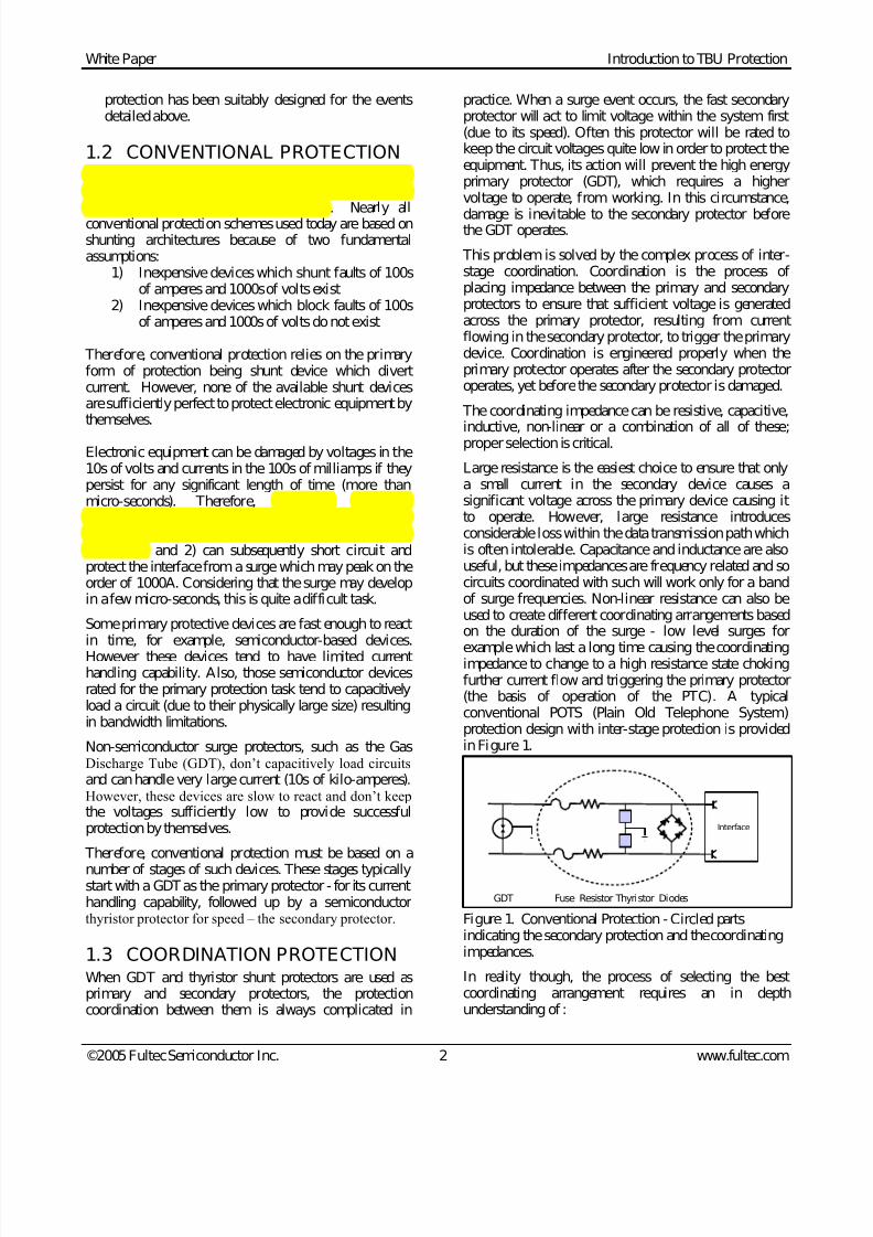
Fultec has developed the TBU to meet the requirementsof the ideal protector described in Section 2. In order tounderstand the operation of the TBU, it is useful topicture the TBU as having a current limiting functionalblock and a voltage disconnect functional block.
Figure 2. TBU functional block diagram
The TBU responds to both over-current and over-voltagefaults as described in the following paragraphs.
LOAD
S
TBUCURRENT
LIMITVOLTAGE
DISCONNECT LOAD
SS
TBUCURRENT
LIMITVOLTAGE
DISCONNECT
CURRENTLIMIT
CURRENTLIMIT
VOLTAGE
DISCONNECT
7/28/2019 TBU Function
http://slidepdf.com/reader/full/tbu-function 4/6
White Paper Introduction to TBU Protection
©2005 Fultec Semiconductor Inc. 4 www.fultec.com
LOAD
Sshort
TBU
CURRENTLIMIT
VOLTAGEDISCONNECT LOAD
SSshort
TBU
CURRENTLIMIT
VOLTAGEDISCONNECT
CURRENTLIMIT
CURRENTLIMIT
VOLTAGEDISCONNECT
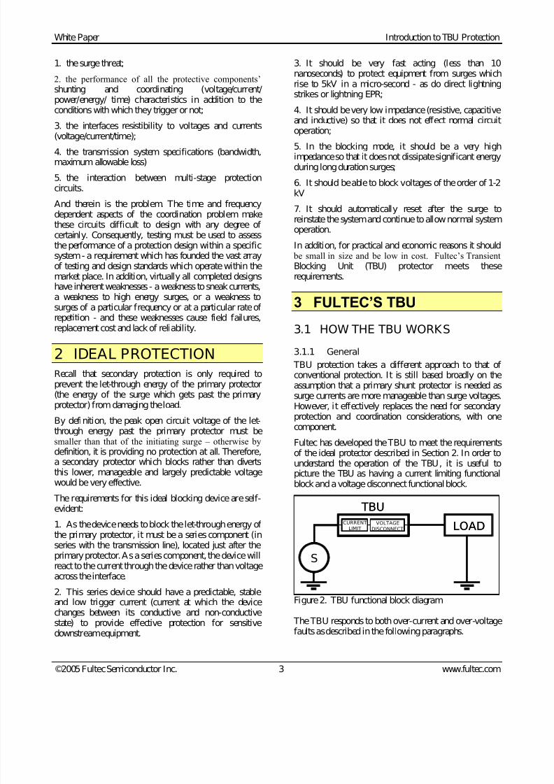
3.1.2 Over-current faults
Figure 3. Over-current fault diagram
With a short circuit event occurring at time 1 (see Figure4), the current rises to the current limiting level of Iout
(time 2, ~10 nano-seconds). At this point, the voltagedisconnect portion of the circuit operates and by time 3(~1 micro-second), the load is disconnected from thesurge. During the remainder of the surge (time 4), the
TBU remains in the protected state of very low current
and voltage at the load.
1
2
3
4
Iout
Iop
Ileak
Vload
Vsource
time
nano-second
reaction time
~1µsec
1
2
3
4
Iout
Iop
Ileak
Vload
Vsource
time
nano-second
reaction time
~1µsec
Figure 4. TBU reaction to a over-current fault
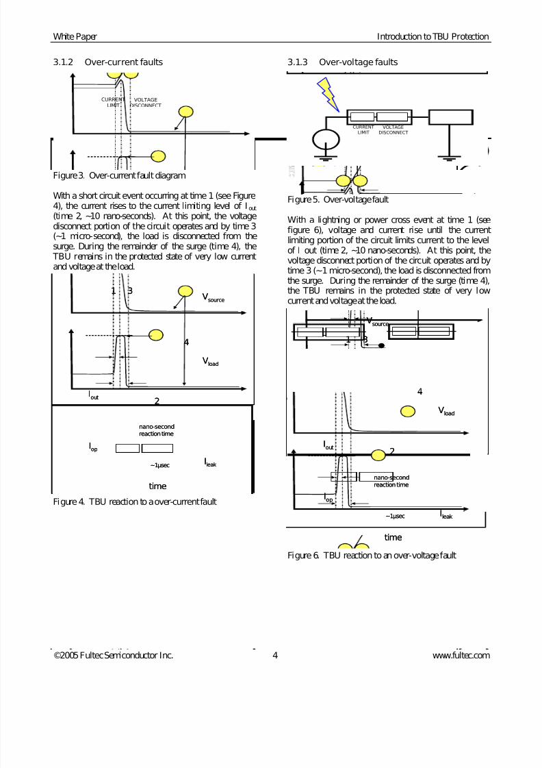
3.1.3 Over-voltage faults
LOAD
S
SURGE TBU
CURRENT
LIMIT
VOLTAGE
DISCONNECT LOAD
SS
SURGE TBU
CURRENT
LIMIT
VOLTAGE
DISCONNECT
CURRENT
LIMIT
CURRENT
LIMIT
VOLTAGE
DISCONNECT
Figure 5. Over-voltage fault
With a lightning or power cross event at time 1 (seefigure 6), voltage and current rise until the currentlimiting portion of the circuit limits current to the levelof I out (time 2, ~10 nano-seconds). At this point, thevoltage disconnect portion of the circuit operates and by
time 3 (~1 micro-second), the load is disconnected fromthe surge. During the remainder of the surge (time 4),the TBU remains in the protected state of very lowcurrent and voltage at the load.
1
2
4
3
time
nano-second
reaction time
Ileak
Vload
Vsource
~1µsec
Iout
Iop
1
2
4
3
time
nano-second
reaction time
Ileak
Vload
Vsource
~1µsec
Iout
Iop
Figure 6. TBU reaction to an over-voltage fault
7/28/2019 TBU Function
http://slidepdf.com/reader/full/tbu-function 5/6
White Paper Introduction to TBU Protection
©2005 Fultec Semiconductor Inc. 5 www.fultec.com
3.2 TBU PERFORMANCE
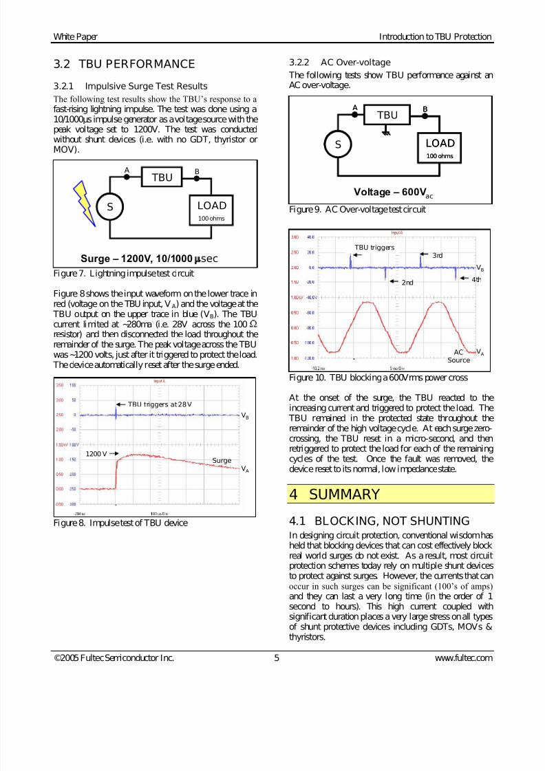
3.2.1 Impulsive Surge Test Results
The following test results show the TBUs response to afast-rising lightning impulse. The test was done using a10/1000µs impulse generator as a voltage source with thepeak voltage set to 1200V. The test was conductedwithout shunt devices (i.e. with no GDT, thyristor orMOV).
LOAD100 ohms
TBU
SS
Surge 1200V, 10/1000 sec
A B
Figure 7. Lightning impulse test circuit
Figure 8 shows the input waveform on the lower trace inred (voltage on the TBU input, VA) and the voltage at the
TBU output on the upper trace in blue (VB). The TBUcurrent limited at ~280ma (i.e. 28V across the 100resistor) and then disconnected the load throughout theremainder of the surge. The peak voltage across the TBUwas ~1200 volts, just after it triggered to protect the load.
The device automatically reset after the surge ended.
Figure 8. Impulse test of TBU device
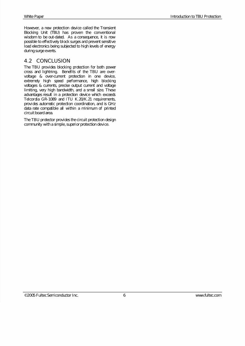
3.2.2 AC Over-voltage
The following tests show TBU performance against anAC over-voltage.
Voltage 600Vac
LOAD100 ohms
S
A B TBU
LOAD100 ohms
SS
A B TBU
Figure 9. AC Over-voltage test circuit
ACSource
TBU triggers
2nd
3rd
4th
VA
VB
Figure 10. TBU blocking a 600Vrms power cross
At the onset of the surge, the TBU reacted to the
increasing current and triggered to protect the load. The TBU remained in the protected state throughout theremainder of the high voltage cycle. At each surge zero-crossing, the TBU reset in a micro-second, and thenretriggered to protect the load for each of the remainingcycles of the test. Once the fault was removed, thedevice reset to its normal, low impedance state.
4 SUMMARY
4.1 BLOCKING, NOT SHUNTING
In designing circuit protection, conventional wisdom hasheld that blocking devices that can cost effectively blockreal world surges do not exist. As a result, most circuitprotection schemes today rely on multiple shunt devicesto protect against surges. However, the currents that canoccur in such surges can be significant (100s of amps)and they can last a very long time (in the order of 1second to hours). This high current coupled withsignificant duration places a very large stress on all typesof shunt protective devices including GDTs, MOVs &thyristors.
Surge1200 V
TBU triggers at 28 V
VA
VB
7/28/2019 TBU Function
http://slidepdf.com/reader/full/tbu-function 6/6
White Paper Introduction to TBU Protection
©2005 Fultec Semiconductor Inc. 6 www.fultec.com
However, a new protection device called the TransientBlocking Unit (TBU) has proven the conventionalwisdom to be out-dated. As a consequence, it is nowpossible to effectively block surges and prevent sensitiveload electronics being subjected to high levels of energyduring surge events.
4.2 CONCLUSION The TBU provides blocking protection for both powercross and lightning. Benefits of the TBU are over-voltage & over-current protection in one device,extremely high speed performance, high blockingvoltages & currents, precise output current and voltagelimiting, very high bandwidth, and a small size. Theseadvantages result in a protection device which exceeds
Telcordia GR-1089 and ITU K.20/K.21 requirements,provides automatic protection coordination, and is GHzdata rate compatible all within a minimum of printedcircuit board area.
The TBU protector provides the circuit protection designcommunity with a simple, superior protection device.