tat operating manual 90421 · tat-8-25t turn around tester for valves operating manual original...
TRANSCRIPT

TAT-8-25TTURN AROUND TESTER FOR
VALVESOPERATING MANUAL
ORIGINAL INSTRUCTIONS
P/N 90421February 2018Revision 1


P/N 90421, Rev. 1 Page A
©2018 CLIMAX or its subsidiaries.All rights reserved.
Except as expressly provided herein, no part of this manual may be reproduced, copied, transmitted, dissem-inated, downloaded, or stored in any storage medium, without the express prior written consent of CLIMAX. CLIMAX hereby grants permission to download a single copy of this manual and of any revision hereto onto an electronic storage medium to be viewed and to print one copy of this manual or any revision hereto, pro-vided that such electronic or printed copy of this manual or revision must contain the complete text of this copyright notice and provided further that any unauthorized commercial distribution of this manual or any revision hereto is prohibited.
At CLIMAX, we value your opinion.
For comments or questions about this manual or other CLIMAX documentation, please [email protected].
For comments or questions about CLIMAX products or services, please call CLIMAX or e-mail [email protected]. For quick and accurate service, please provide your representative with the following:
• Your name• Shipping address• Telephone number• Machine model• Serial number (if applicable)• Date of purchase
CLIMAX World Headquarters
2712 East 2nd Street Newberg, Oregon 97132 USA
Telephone (worldwide): +1-503-538-2815Toll-free (North America): 1-800-333-8311Fax: 503-538-7600
H&S Tool World Headquarters
715 Weber Dr.Wadsworth, OH 44281 USA
Telephone: +1-330-336-4550Fax: 1-330-336-9159hstool.com
CLIMAX | H&S Tool (UK Headquarters)
Unit 7 Castlehill Industrial EstateBredbury Industrial ParkHorsfield WayStockport SK6 2SU, UK
Telephone: +44 (0) 161-406-1720
CLIMAX | H&S Tool (European Headquarters)
Am Langen Graben 852353 Düren, Germany
Telephone: +49 (0) 242-191-7712E-mail: [email protected]
CLIMAX | H&S Tool (Asia Pacific Head-quarters)
316 Tanglin Road #02-01Singapore 247978
Telephone: +65-9647-2289 Fax: +65-6801-0699
CLIMAX | H&S Tool (Middle East Headquarters)
Warehouse #5, Plot: 369 272 Um Sequim RoadAl Quoz 4PO Box 414 084Dubai, UAE
Telephone: +971-04-321-0328

Page B TAT Operating Manual
CLIMAX GLOBAL LOCATIONS

P/N 90421, Rev. 1 Page C
CE DOCUMENTATION
Page D TAT Operating Manual
LIMITED WARRANTY
CLIMAX Portable Machine Tools, Inc. (hereafter referred to as “CLIMAX”) warrants that all new machines are free from defects in materials and workmanship. This warranty is available to the original purchaser for a period of two years after delivery. If the original purchaser finds any defect in materials or workmanship within the warranty period, the original purchaser should contact its factory representative and return the entire machine, shipping prepaid, to the factory. CLIMAX will, at its option, either repair or replace the defective machine at no charge and will return the machine with shipping prepaid.
CLIMAX warrants that all parts are free from defects in materials and workmanship, and that all labor has been performed properly. This warranty is available to the customer purchasing parts or labor for a period of 90 days after delivery of the part or repaired machine or 180 days on used machines and components. If the customer purchasing parts or labor finds any defect in materials or workmanship within the warranty period, the purchaser should contact its factory representative and return the part or repaired machine, shipping pre-paid, to the factory. CLIMAX will, at its option, either repair or replace the defective part and/ or correct any defect in the labor performed, both at no charge, and return the part or repaired machine shipping prepaid.
These warranties do not apply to the following:
• Damage after the date of shipment not caused by defects in materials or workmanship• Damage caused by improper or inadequate machine maintenance• Damage caused by unauthorized machine modification or repair• Damage caused by machine abuse• Damage caused by using the machine beyond its rated capacity
All other warranties, express or implied, including without limitation the warranties of merchantability and fitness for a particular purpose are disclaimed and excluded.
Terms of sale
Be sure to review the terms of sale which appear on the reverse side of your invoice. These terms control and limit your rights with respect to the goods purchased from CLIMAX.
About this manual
CLIMAX provides the contents of this manual in good faith as a guideline to the operator. CLIMAX cannot guarantee that the information contained in this manual is correct for applications other than the application described in this manual. Product specifications are subject to change without notice.

P/N 90421, Rev. 1 Page i
TABLE OF CONTENTS
CHAPTER/SECTION PAGE 1 INTRODUCTION - - - - - - - - - - - - - - - - - - - - - - - - - - - - - - - - - - - - - - - - - - - - - - - - - - - - - - -1
1.1 HOW TO USE THIS MANUAL . . . . . . . . . . . . . . . . . . . . . . . . . . . . . . . . . . . . . . . . . . . . . . . . . . . . . . . . . . 11.2 SAFETY ALERTS . . . . . . . . . . . . . . . . . . . . . . . . . . . . . . . . . . . . . . . . . . . . . . . . . . . . . . . . . . . . . . . . . . 11.3 GENERAL SAFETY PRECAUTIONS. . . . . . . . . . . . . . . . . . . . . . . . . . . . . . . . . . . . . . . . . . . . . . . . . . . . . . 21.4 MACHINE-SPECIFIC SAFETY PRECAUTIONS. . . . . . . . . . . . . . . . . . . . . . . . . . . . . . . . . . . . . . . . . . . . . . . 31.5 RISK ASSESSMENT AND HAZARD MITIGATION . . . . . . . . . . . . . . . . . . . . . . . . . . . . . . . . . . . . . . . . . . . . . 41.6 RISK ASSESSMENT CHECKLIST . . . . . . . . . . . . . . . . . . . . . . . . . . . . . . . . . . . . . . . . . . . . . . . . . . . . . . . 51.7 LABELS . . . . . . . . . . . . . . . . . . . . . . . . . . . . . . . . . . . . . . . . . . . . . . . . . . . . . . . . . . . . . . . . . . . . . . . . 6
1.7.1 Label identification . . . . . . . . . . . . . . . . . . . . . . . . . . . . . . . . . . . . . . . . . . . . . . . . . . . . . . . . . . 6
1.7.2 Label location . . . . . . . . . . . . . . . . . . . . . . . . . . . . . . . . . . . . . . . . . . . . . . . . . . . . . . . . . . . . . . 8
2 OVERVIEW - - - - - - - - - - - - - - - - - - - - - - - - - - - - - - - - - - - - - - - - - - - - - - - - - - - - - - - - - 112.1 FEATURES AND COMPONENTS. . . . . . . . . . . . . . . . . . . . . . . . . . . . . . . . . . . . . . . . . . . . . . . . . . . . . . . 112.2 CONTROLS. . . . . . . . . . . . . . . . . . . . . . . . . . . . . . . . . . . . . . . . . . . . . . . . . . . . . . . . . . . . . . . . . . . . . 132.3 DIMENSIONS . . . . . . . . . . . . . . . . . . . . . . . . . . . . . . . . . . . . . . . . . . . . . . . . . . . . . . . . . . . . . . . . . . . 142.4 SPECIFICATIONS. . . . . . . . . . . . . . . . . . . . . . . . . . . . . . . . . . . . . . . . . . . . . . . . . . . . . . . . . . . . . . . . . 162.5 ITEMS REQUIRED BUT NOT SUPPLIED. . . . . . . . . . . . . . . . . . . . . . . . . . . . . . . . . . . . . . . . . . . . . . . . . . 16
3 SETUP - - - - - - - - - - - - - - - - - - - - - - - - - - - - - - - - - - - - - - - - - - - - - - - - - - - - - - - - - - - - - 173.1 RECEIPT AND INSPECTION . . . . . . . . . . . . . . . . . . . . . . . . . . . . . . . . . . . . . . . . . . . . . . . . . . . . . . . . . 173.2 LIFTING AND RIGGING . . . . . . . . . . . . . . . . . . . . . . . . . . . . . . . . . . . . . . . . . . . . . . . . . . . . . . . . . . . . . 173.3 SECURING THE TEST STAND . . . . . . . . . . . . . . . . . . . . . . . . . . . . . . . . . . . . . . . . . . . . . . . . . . . . . . . . 19
3.3.1 Bolting the test stand to a service vehicle . . . . . . . . . . . . . . . . . . . . . . . . . . . . . . . . . . . . . . . . 19
3.3.2 Strapping the test stand to a service vehicle. . . . . . . . . . . . . . . . . . . . . . . . . . . . . . . . . . . . . . 19
3.4 FILLING THE RESERVOIRS AND LUBRICATOR . . . . . . . . . . . . . . . . . . . . . . . . . . . . . . . . . . . . . . . . . . . . 203.5 CONNECTING AIR FROM THE SOURCE . . . . . . . . . . . . . . . . . . . . . . . . . . . . . . . . . . . . . . . . . . . . . . . . . 203.6 CLAMPING PROCEDURE . . . . . . . . . . . . . . . . . . . . . . . . . . . . . . . . . . . . . . . . . . . . . . . . . . . . . . . . . . . 20
4 OPERATION - - - - - - - - - - - - - - - - - - - - - - - - - - - - - - - - - - - - - - - - - - - - - - - - - - - - - - - - 234.1 PRE-OPERATION CHECKS . . . . . . . . . . . . . . . . . . . . . . . . . . . . . . . . . . . . . . . . . . . . . . . . . . . . . . . . . . 234.2 CONDUCTING AN AIR TEST . . . . . . . . . . . . . . . . . . . . . . . . . . . . . . . . . . . . . . . . . . . . . . . . . . . . . . . . . 24
4.2.1 Test procedure . . . . . . . . . . . . . . . . . . . . . . . . . . . . . . . . . . . . . . . . . . . . . . . . . . . . . . . . . . . . 24
4.2.2 Adjusting the valve on the seal plate. . . . . . . . . . . . . . . . . . . . . . . . . . . . . . . . . . . . . . . . . . . . 24
4.3 CONDUCTING HYDROSTATIC OR WATER TEST . . . . . . . . . . . . . . . . . . . . . . . . . . . . . . . . . . . . . . . . . . . 24
4.3.1 Test procedure . . . . . . . . . . . . . . . . . . . . . . . . . . . . . . . . . . . . . . . . . . . . . . . . . . . . . . . . . . . . 24
4.3.2 Adjusting the valve on the seal plate. . . . . . . . . . . . . . . . . . . . . . . . . . . . . . . . . . . . . . . . . . . . 25
4.4 RELEASING THE CLAMP . . . . . . . . . . . . . . . . . . . . . . . . . . . . . . . . . . . . . . . . . . . . . . . . . . . . . . . . . . . 254.5 PREPARING THE MACHINE FOR TRANSPORT. . . . . . . . . . . . . . . . . . . . . . . . . . . . . . . . . . . . . . . . . . . . . 26
5 MAINTENANCE - - - - - - - - - - - - - - - - - - - - - - - - - - - - - - - - - - - - - - - - - - - - - - - - - - - - - - 275.1 MAINTENANCE CHECKLIST . . . . . . . . . . . . . . . . . . . . . . . . . . . . . . . . . . . . . . . . . . . . . . . . . . . . . . . . . 27
Page ii TAT Operating Manual
TABLE OF CONTENTS (CONTINUED)
CHAPTER/SECTION PAGE5.2 TROUBLESHOOTING . . . . . . . . . . . . . . . . . . . . . . . . . . . . . . . . . . . . . . . . . . . . . . . . . . . . . . . . . . . . . . 27
6 STORAGE AND SHIPPING - - - - - - - - - - - - - - - - - - - - - - - - - - - - - - - - - - - - - - - - - - - - - 296.1 STORAGE . . . . . . . . . . . . . . . . . . . . . . . . . . . . . . . . . . . . . . . . . . . . . . . . . . . . . . . . . . . . . . . . . . . . . 29
6.1.1 Short-term storage . . . . . . . . . . . . . . . . . . . . . . . . . . . . . . . . . . . . . . . . . . . . . . . . . . . . . . . . . 29
6.1.2 Long-term storage. . . . . . . . . . . . . . . . . . . . . . . . . . . . . . . . . . . . . . . . . . . . . . . . . . . . . . . . . . 29
6.2 SHIPPING. . . . . . . . . . . . . . . . . . . . . . . . . . . . . . . . . . . . . . . . . . . . . . . . . . . . . . . . . . . . . . . . . . . . . . 306.3 DECOMMISSIONING . . . . . . . . . . . . . . . . . . . . . . . . . . . . . . . . . . . . . . . . . . . . . . . . . . . . . . . . . . . . . . 30
APPENDIX A ASSEMBLY DRAWINGS - - - - - - - - - - - - - - - - - - - - - - - - - - - - - - - - - - - - - 31
APPENDIX B SCHEMATICS - - - - - - - - - - - - - - - - - - - - - - - - - - - - - - - - - - - - - - - - - - - - - 47
APPENDIX C SDS - - - - - - - - - - - - - - - - - - - - - - - - - - - - - - - - - - - - - - - - - - - - - - - - - - - - 49
P/N 90421, Rev. 1 Page iii
LIST OF FIGURES
FIGURE PAGE1-1 Console label locations . . . . . . . . . . . . . . . . . . . . . . . . . . . . . . . . . . . . . . . . . . . . . . . . . . . . . . . . . . . . . . 81-2 Rear left label locations . . . . . . . . . . . . . . . . . . . . . . . . . . . . . . . . . . . . . . . . . . . . . . . . . . . . . . . . . . . . . . 91-3 Rear right label locations . . . . . . . . . . . . . . . . . . . . . . . . . . . . . . . . . . . . . . . . . . . . . . . . . . . . . . . . . . . . 101-4 Rear label locations . . . . . . . . . . . . . . . . . . . . . . . . . . . . . . . . . . . . . . . . . . . . . . . . . . . . . . . . . . . . . . . . 102-1 Front components . . . . . . . . . . . . . . . . . . . . . . . . . . . . . . . . . . . . . . . . . . . . . . . . . . . . . . . . . . . . . . . . . 122-2 Back components . . . . . . . . . . . . . . . . . . . . . . . . . . . . . . . . . . . . . . . . . . . . . . . . . . . . . . . . . . . . . . . . . 122-3 Upper console controls . . . . . . . . . . . . . . . . . . . . . . . . . . . . . . . . . . . . . . . . . . . . . . . . . . . . . . . . . . . . . 132-4 Lower console controls . . . . . . . . . . . . . . . . . . . . . . . . . . . . . . . . . . . . . . . . . . . . . . . . . . . . . . . . . . . . . 142-5 Back console ports . . . . . . . . . . . . . . . . . . . . . . . . . . . . . . . . . . . . . . . . . . . . . . . . . . . . . . . . . . . . . . . . 142-6 Dimensions . . . . . . . . . . . . . . . . . . . . . . . . . . . . . . . . . . . . . . . . . . . . . . . . . . . . . . . . . . . . . . . . . . . . . . 153-1 TAT-8-25T lifting and securing points (left side) . . . . . . . . . . . . . . . . . . . . . . . . . . . . . . . . . . . . . . . . . . 183-2 TAT-8-25T lifting and securing points (right side) . . . . . . . . . . . . . . . . . . . . . . . . . . . . . . . . . . . . . . . . . 183-3 TAT-8-25T shipping tie-downs . . . . . . . . . . . . . . . . . . . . . . . . . . . . . . . . . . . . . . . . . . . . . . . . . . . . . . . 194-1 Shipping strap and seal cover . . . . . . . . . . . . . . . . . . . . . . . . . . . . . . . . . . . . . . . . . . . . . . . . . . . . . . . . 26A-1 TAT-8-25T assembly front detail (P/N 88970) . . . . . . . . . . . . . . . . . . . . . . . . . . . . . . . . . . . . . . . . . . . 32A-2 TAT-8-25T assembly back detail (P/N 88970) . . . . . . . . . . . . . . . . . . . . . . . . . . . . . . . . . . . . . . . . . . . 33A-3 TAT-8-25T assembly exploded view detail(P/N 88970) . . . . . . . . . . . . . . . . . . . . . . . . . . . . . . . . . . . . 34A-4 TAT-8-25T assembly parts list 1 (P/N 88970). . . . . . . . . . . . . . . . . . . . . . . . . . . . . . . . . . . . . . . . . . . . 35A-5 TAT-8-25T assembly parts list 2 (P/N 88970). . . . . . . . . . . . . . . . . . . . . . . . . . . . . . . . . . . . . . . . . . . . 36A-6 Console assembly front detail (P/N 89417). . . . . . . . . . . . . . . . . . . . . . . . . . . . . . . . . . . . . . . . . . . . . . 37A-7 Console assembly back detail (P/N 89417) . . . . . . . . . . . . . . . . . . . . . . . . . . . . . . . . . . . . . . . . . . . . . 38A-8 Console assembly back detail with panel removed (P/N 89417) . . . . . . . . . . . . . . . . . . . . . . . . . . . . . 39A-9 Console assembly front labels (P/N 89417) . . . . . . . . . . . . . . . . . . . . . . . . . . . . . . . . . . . . . . . . . . . . . 40A-10 Console assembly back labels (P/N 89417) . . . . . . . . . . . . . . . . . . . . . . . . . . . . . . . . . . . . . . . . . . . . 41A-11 Console assembly parts list 1 (P/N 89417) . . . . . . . . . . . . . . . . . . . . . . . . . . . . . . . . . . . . . . . . . . . . . 42A-12 Console assembly parts list 2 (P/N 89417) . . . . . . . . . . . . . . . . . . . . . . . . . . . . . . . . . . . . . . . . . . . . . 43A-13 Clamp arm assembly (P/N 89416) . . . . . . . . . . . . . . . . . . . . . . . . . . . . . . . . . . . . . . . . . . . . . . . . . . . 44B-1 Schematic (P/N 90024) . . . . . . . . . . . . . . . . . . . . . . . . . . . . . . . . . . . . . . . . . . . . . . . . . . . . . . . . . . . . . 47

Page iv TAT Operating Manual
This page intentionally left blank

P/N 90421, Rev. 1 Page v
LIST OF TABLES
TABLE PAGE1-1 Risk assessment checklist before set-up . . . . . . . . . . . . . . . . . . . . . . . . . . . . . . . . . . . . . . . . . . . . . . . . 51-2 Risk assessment checklist after set-up . . . . . . . . . . . . . . . . . . . . . . . . . . . . . . . . . . . . . . . . . . . . . . . . . . 51-3 TAT-8-25T labels. . . . . . . . . . . . . . . . . . . . . . . . . . . . . . . . . . . . . . . . . . . . . . . . . . . . . . . . . . . . . . . . . . . 62-1 Console control identification. . . . . . . . . . . . . . . . . . . . . . . . . . . . . . . . . . . . . . . . . . . . . . . . . . . . . . . . . 132-2 Specifications . . . . . . . . . . . . . . . . . . . . . . . . . . . . . . . . . . . . . . . . . . . . . . . . . . . . . . . . . . . . . . . . . . . . 163-1 Hydraulic load chart for flanged valves . . . . . . . . . . . . . . . . . . . . . . . . . . . . . . . . . . . . . . . . . . . . . . . . . 225-1 Maintenance intervals and tasks . . . . . . . . . . . . . . . . . . . . . . . . . . . . . . . . . . . . . . . . . . . . . . . . . . . . . . 27A-1 O-rings kit P/N 90025 . . . . . . . . . . . . . . . . . . . . . . . . . . . . . . . . . . . . . . . . . . . . . . . . . . . . . . . . . . . . . . 45

Page vi TAT Operating Manual
This page intentionally left blank
P/N 90421, Rev. 1 Page 1
1 INTRODUCTIONIN THIS CHAPTER:1.1 HOW TO USE THIS MANUAL - - - - - - - - - - - - - - - - - - - - - - - - - - - - - - - - - - - - - - 11.2 SAFETY ALERTS - - - - - - - - - - - - - - - - - - - - - - - - - - - - - - - - - - - - - - - - - - - 11.3 GENERAL SAFETY PRECAUTIONS - - - - - - - - - - - - - - - - - - - - - - - - - - - - - - - - - - - 21.4 MACHINE-SPECIFIC SAFETY PRECAUTIONS - - - - - - - - - - - - - - - - - - - - - - - - - - - - - - - 31.5 RISK ASSESSMENT AND HAZARD MITIGATION - - - - - - - - - - - - - - - - - - - - - - - - - - - - - - 41.6 RISK ASSESSMENT CHECKLIST - - - - - - - - - - - - - - - - - - - - - - - - - - - - - - - - - - - - 51.7 LABELS - - - - - - - - - - - - - - - - - - - - - - - - - - - - - - - - - - - - - - - - - - - - - - - 6
1.7.1 LABEL IDENTIFICATION - - - - - - - - - - - - - - - - - - - - - - - - - - - - - - - - - - - - - 61.7.2 LABEL LOCATION - - - - - - - - - - - - - - - - - - - - - - - - - - - - - - - - - - - - - - - - 8
1.1 HOW TO USE THIS MANUAL
This manual describes information necessary for the setup, operation, mainte-nance, storage, shipping, and decommissioning of the TAT-8-25T.
The first page of each chapter includes a summary of the chapter contents to help you locate specific information. The appendices contain supplemental product information to aid in setup, operation, and maintenance tasks.
Read this entire manual to familiarize yourself with the TAT-8-25T before attempt-ing to set it up or operate it.
1.2 SAFETY ALERTS
Pay careful attention to the safety alerts printed throughout this manual. Safety alerts will call your attention to specific hazardous situations that may be encoun-tered when operating this machine.
Examples of safety alerts used in this manual are defined here1:
DANGERindicates a hazardous situation which, if not avoided, WILL result in death or severe injury.
WARNINGindicates a hazardous situation which, if not avoided, COULD result in death or severe injury.
1. For more information on safety alerts, refer to ANSI/NEMA Z535.6-2011, Product safety Information in Product Manuals, Instructions, and Other Collateral Materials.

Page 2 TAT Operating Manual
CAUTIONindicates a hazardous situation which, if not avoided, could result in minor or moderate injury.
NOTICEindicates a hazardous situation which, if not avoided, could result in property damage, equipment failure, or undesired work results.
1.3 GENERAL SAFETY PRECAUTIONS
CLIMAX leads the way in promoting the safe use of portable machine tools and valve testers. Safety is a joint effort. You, the end user, must do your part by being aware of your work environment and closely following the operating procedures and safety precautions contained in this manual, as well as your employer’s safety guidelines.
Observe the following safety precautions when operating or working around the machine.
Training – Before operating this or any machine tool, you should receive instruction from a qualified trainer. Contact CLIMAX for machine-specific training information.
Risk assessment – Working with and around this machine poses risks to your safety. You, the end user, are responsible for conducting a risk assess-ment of each job site before setting up and operating this machine.
Intended use – Use this machine in accordance with the instructions and precautions in this manual. Do not use this machine for any purpose other than its intended use as described in this manual.
Personal protective equipment – Always wear appropriate personal pro-tective gear when operating this or any other machine tool.
Work area – Keep the work area around the machine clear of clutter. Restrain cords and hoses connected to the machine. Keep other cords and hoses away from the work area.
Lifting – Many CLIMAX machine components are very heavy. Whenever possible, lift the machine or its components using proper hoisting equip-ment and rigging. Always use designated lifting points on the machine.
Lock-out/tag-out – Lock-out and tag-out the machine before performing maintenance.
Moving parts – CLIMAX machines have numerous exposed moving parts and interfaces that can cause severe impact, pinching, cutting, and other injuries. Except for stationary operating controls, avoid contact with mov-

P/N 90421, Rev. 1 Page 3
ing parts by hands or tools during machine operation. Remove gloves and secure hair, clothing, jewelry, and pocket items to prevent them from becoming entangled in moving parts.
1.4 MACHINE-SPECIFIC SAFETY PRECAUTIONS
Eye hazard – Always wear eye protection when operating the machine.
Sound level – This machine produces potentially harmful sound levels. Hearing protection is required when operating this machine or working around it.
Hazardous environments – Do not operate the machine in environments where potentially explosive materials, toxic chemicals, or radiation may be present.
Pressurization – Do not over-pressurize the valve test system beyond the limits described in this manual and on machine labels.
Test gauges – Do not use any gauge above its rating. Do not remove test gauges while the system is pressurized.
Utility service requirements – Do not exceed the pressure ratings stated in this manual and on the machine labels.
WARNINGThis machine is equipped with interlocking valve control knobs to prevent accidental release of clamp pressure while the valve under test is pressurized.
Do not operate this machine if these interlocking knobs are missing, damaged, or altered. Doing so could result in property damage or personnel injury.

Page 4 TAT Operating Manual
1.5 RISK ASSESSMENT AND HAZARD MITIGATION
To achieve the intended results and to promote safety, the operator must under-stand and follow the design intent, set-up, and operation practices that are unique to valve testers.
The operator must perform an overall review and on-site risk assessment of the intended application. Due to the unique nature of high-pressure hydrostatic testing, identifying one or more hazards that must be addressed is typical.
When performing the on-site risk assessment, it is important to consider the valve tester and the workpiece as a whole.
WARNINGHigh-pressure valve testing may result in the sudden, unexpected release of stored energy with the potential to cause property damage or personnel injury. Potential hazards may include the possibility of high-velocity fluid escaping and high-energy projectile impact. The end-user must assess the application and install protective barrier devices, as appropriate.
P/N 90421, Rev. 1 Page 5
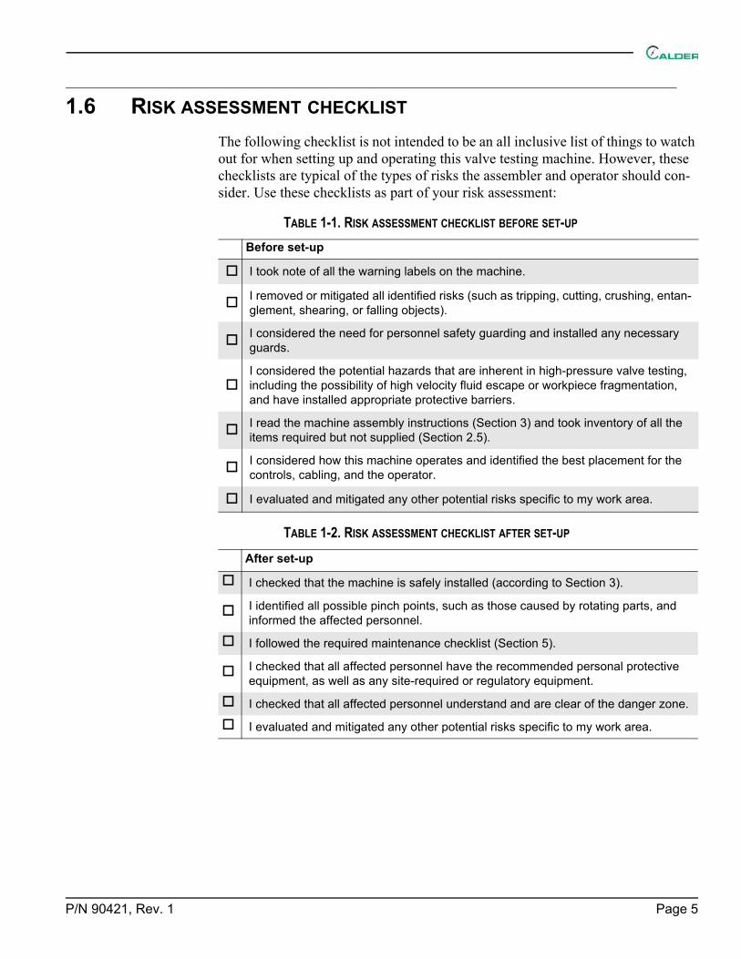
1.6 RISK ASSESSMENT CHECKLIST
The following checklist is not intended to be an all inclusive list of things to watch out for when setting up and operating this valve testing machine. However, these checklists are typical of the types of risks the assembler and operator should con-sider. Use these checklists as part of your risk assessment:
TABLE 1-1. RISK ASSESSMENT CHECKLIST BEFORE SET-UP
Before set-up
I took note of all the warning labels on the machine.
I removed or mitigated all identified risks (such as tripping, cutting, crushing, entan-glement, shearing, or falling objects).
I considered the need for personnel safety guarding and installed any necessary guards.
I considered the potential hazards that are inherent in high-pressure valve testing, including the possibility of high velocity fluid escape or workpiece fragmentation, and have installed appropriate protective barriers.
I read the machine assembly instructions (Section 3) and took inventory of all the items required but not supplied (Section 2.5).
I considered how this machine operates and identified the best placement for the controls, cabling, and the operator.
I evaluated and mitigated any other potential risks specific to my work area.
TABLE 1-2. RISK ASSESSMENT CHECKLIST AFTER SET-UP
After set-up
I checked that the machine is safely installed (according to Section 3).
I identified all possible pinch points, such as those caused by rotating parts, and informed the affected personnel.
I followed the required maintenance checklist (Section 5).
I checked that all affected personnel have the recommended personal protective equipment, as well as any site-required or regulatory equipment.
I checked that all affected personnel understand and are clear of the danger zone.
I evaluated and mitigated any other potential risks specific to my work area.

Page 6 TAT Operating Manual
1.7 LABELS
1.7.1 Label identification
The following warning and identification labels should be on your machine. If any are defaced or missing, contact CLIMAX immediately for replacements.
TABLE 1-3. TAT-8-25T LABELS
P/N 29154
ID plate
P/N 59033
Label: center of balance
P/N 59039
Label: lift point
P/N 79328
Warning label: read the operating manual
P/N 80905
Warning label: hand crush hazard
P/N 81008
Warning label: wear ear and eye protection
P/N 82144
Warning label: danger, use caution
P/N 90160
Warning label: high-pressure water release haz-ard

P/N 90421, Rev. 1 Page 7
P/N 89496
Warning label: not for HP gas testing
P/N 89497
Warning label: do not exceed the maximum pres-sure rating of the valve
P/N 89498
Warning label: do not release the clamp the valve is pres-surized
P/N 89499
Warning label: do not lift with valve clamped
P/N 89500
Warning label: tip-over hazard
P/N 90533
Label: clamp arm shipping strap
P/N 90534
Label: frame tie-down points
P/N 90585
Label: Calder TAT
TABLE 1-3. TAT-8-25T LABELS

Page 8 TAT Operating Manual
1.7.2 Label location
The following figures display the location of the labels on each of the components of the TAT-8-25T. For further identification of location placement, refer to the exploded views in Appendix A.
P/N 90585
Label: Calder Turn-Around-Tester
TABLE 1-3. TAT-8-25T LABELS
FIGURE 1-1. CONSOLE LABEL LOCATIONS
Label P/N: 29154, 79328, 81008, 82144, 89494, 89496, 89497, 89498, 89499, 89500, 90585

P/N 90421, Rev. 1 Page 9
FIGURE 1-2. REAR LEFT LABEL LOCATIONS
Label P/N: 59033, 59039, 80905, 89499, 90533, 90534, 90585

Page 10 TAT Operating Manual
FIGURE 1-3. REAR RIGHT LABEL LOCATIONS
Label P/N: 59039, 80905, 90585
FIGURE 1-4. REAR LABEL LOCATIONS
Label P/N: 80905

P/N 90421, Rev. 1 Page 11
2 OVERVIEWIN THIS CHAPTER:2.1 FEATURES AND COMPONENTS - - - - - - - - - - - - - - - - - - - - - - - - - - - - - - - - - - - - -112.2 CONTROLS - - - - - - - - - - - - - - - - - - - - - - - - - - - - - - - - - - - - - - - - - - - - -132.3 DIMENSIONS - - - - - - - - - - - - - - - - - - - - - - - - - - - - - - - - - - - - - - - - - - - - -142.4 SPECIFICATIONS - - - - - - - - - - - - - - - - - - - - - - - - - - - - - - - - - - - - - - - - - - -162.5 ITEMS REQUIRED BUT NOT SUPPLIED - - - - - - - - - - - - - - - - - - - - - - - - - - - - - - - - - -16
2.1 FEATURES AND COMPONENTS
The TAT-8-25T is a valve-testing system that hydraulically clamps and seals flanged valves for hydrostatic and low-pressure air testing.
Principal components of the TAT-8-25T include:
Test console – this controls the test pressure of the valve being tested.
Clamp fixture – this holds the valve being tested and maintains a seal between the test equipment and the valve being tested.
Safety interlock – this prevents accidental release of valve clamp hydraulic pressure which the valve under test is pressurized.
The following optional components are sold separately:
Seat leakage fixtures – these capture and measure leakage with a bubble jar (API 527 compliant).
Hydrostatic dampening system – this option allows a more steady pres-sure application to a safety relief valve (SRV) for cracking tests, as the pulsing from the pressure pump reduces with the charged pressure vessel. The maximum pressure is 4,800 psig (331 bar).

Page 12 TAT Operating Manual
Figure 2-1 shows the TAT-8-25T components.
FIGURE 2-1. FRONT COMPONENTS
FIGURE 2-2. BACK COMPONENTS
AIR CONDITIONING ASSEMBLY
AIR BAG
CONTROL CONSOLE
SPLASH SCREEN
SEAL PLATE
CLAMP ARM
BASE FRAME
SUSPENSION FRAME
AIR SUPPLY
SEAL PLATE COVER
HYDRAULIC TANK
TEST FLUID TANK
STORAGE HOOK FOR SEAL PLATE COVER AND SHIPPING STRAP
SHIPPING STRAP

P/N 90421, Rev. 1 Page 13
The following maximum pressure limitations apply:
• Test pressure: 9,600 psi (662 bar) in water; 125 psi (8.6 bar) for air• Clamp pressure: 5,700 psi (393 bar) in hydraulic
2.2 CONTROLS
The controls are all located on the control console and the clamp fixture console.
FIGURE 2-3. UPPER CONSOLE CONTROLS
Table 2-1 defines the clamp console controls, moving clockwise from the top.
V-03
P-02
PCV-04
P1-03<5700 PSI (393 BAR)
V-06 V-02
P-01
DV-01
P1-02<9600 PSI (662 BAR)
P1-01 <125 PSI (8.6 BAR)
V-05
T-01
T-02
PCV-02
TABLE 2-1. CONSOLE CONTROL IDENTIFICATION
Console label Function
P1-03 Clamp pressure gauge
P1-02 Hydrostatic test pressure gauge
P1-01 Low air test pressure gauge
DV-01 Check valve
P-01 Clamp pump
V-02 Test selection valve
PCV-02 Test pressure control valve
T-01 Hydrostatic fluid tank
V-05 Body drain valve
V-06 Clamp release valve

Page 14 TAT Operating Manual
FIGURE 2-4. LOWER CONSOLE CONTROLS
FIGURE 2-5. BACK CONSOLE PORTS
2.3 DIMENSIONS
Figure 2-6 on page 15 shows the machine dimensions.
T-02 Hydraulic fluid tank
P-02 Hydrostatic pump
V-03 Clamp pump air supply valve
PCV-04 Clamp pressure control valve
TABLE 2-1. CONSOLE CONTROL IDENTIFICATION
Console label Function
AIR SUPPLYAIR LUBRICANT FILL
100–150 PSI (7–10 BAR)
300–9600 PSI (21–662 BAR)

P/N 90421, Rev. 1 Page 15
FIGURE 2-6. DIMENSIONS
DIM
ENSI
ON
AL D
ETAI
LSC
ALE
1 : 1
4
41.0
4
42.0
0
�1.
25 T
YP
23.7
418
.93
67.3
8

Page 16 TAT Operating Manual
2.4 SPECIFICATIONS
WARNINGDo not use the machine in any application that exceeds these operating specifications. Failure to follow these guidelines could result in personnel injury and property damage, and will void the warranty.
2.5 ITEMS REQUIRED BUT NOT SUPPLIED
The following items are required but not supplied in your CLIMAX product kit:
• Shop air (100–150 psi [6.9–10.3 bar])• Hydraulic fluid AW-32 or AW-46• Air tool oil (general purpose, such as AW-32)• Lock-out/tag-out device
TABLE 2-2. SPECIFICATIONS
Test media: Water or air
Maximum water test pressure: 9,600 psi (662 bar)
Maximum air test pressure: 125 psi (8.6 bar)
Types of valves that can be tested:Straight pattern ball, globe, gate, butterfly, check, and safety relief valves
Shop air required:100–150 psi at 40 scfm (6.9–10.3 bar at 1.1 m3/min)
Hydraulic ram force: 25 tons (22.7 tonnes)
Approximate machine weight 1,810 lbs (821 kg) with water
Approximate shipped weight 2,500 lbs (1,134 kg)

P/N 90421, Rev. 1 Page 17
3 SETUPIN THIS CHAPTER:3.1 RECEIPT AND INSPECTION - - - - - - - - - - - - - - - - - - - - - - - - - - - - - - - - - - - - - -173.2 LIFTING AND RIGGING - - - - - - - - - - - - - - - - - - - - - - - - - - - - - - - - - - - - - - - - -173.3 SECURING THE TEST STAND - - - - - - - - - - - - - - - - - - - - - - - - - - - - - - - - - - - - - -19
3.3.1 BOLTING THE TEST STAND TO A SERVICE VEHICLE - - - - - - - - - - - - - - - - - - - - - - - -193.3.2 STRAPPING THE TEST STAND TO A SERVICE VEHICLE - - - - - - - - - - - - - - - - - - - - - - -19
3.4 FILLING THE RESERVOIRS AND LUBRICATOR - - - - - - - - - - - - - - - - - - - - - - - - - - - - - -203.5 CONNECTING AIR FROM THE SOURCE - - - - - - - - - - - - - - - - - - - - - - - - - - - - - - - - -203.6 CLAMPING PROCEDURE - - - - - - - - - - - - - - - - - - - - - - - - - - - - - - - - - - - - - - - -20
This section describes the setup and assembly procedures for the TAT-8-25T.
3.1 RECEIPT AND INSPECTION
Your CLIMAX product was inspected and tested prior to shipment, and packaged for normal shipment conditions. CLIMAX does not guarantee the condition of your machine upon delivery.
When you receive your CLIMAX product, perform the following receipt checks:
1. Inspect the shipping containers for damage.
2. Check the contents of the shipping containers against the included invoice to make sure that all components have been shipped.
3. Inspect all components for damage.
Contact CLIMAX immediately to report damaged or missing components.
NOTICEKeep the shipping container and all packing materials for future storage and shipping of the machine.
3.2 LIFTING AND RIGGING
Lift the TAT-8-25T at the 3-mark point with straps attached, as seen in Figure 3-1 and Figure 3-2 on page 18.

Page 18 TAT Operating Manual
FIGURE 3-1. TAT-8-25T LIFTING AND SECURING POINTS (LEFT SIDE)
FIGURE 3-2. TAT-8-25T LIFTING AND SECURING POINTS (RIGHT SIDE)
LIFTING POINTHOLES TO SECURE THE TESTER TO THE VEHICLE
LIFTING POINTS

P/N 90421, Rev. 1 Page 19
3.3 SECURING THE TEST STAND
The TAT-8-25T has been designed with portability in mind. The service vehicle to transport the TAT-8-25T must have the appropriate weight rating for the test stand and other testing tools included.
3.3.1 Bolting the test stand to a service vehicle
When the test stand must be permanently installed on a vehicle, use the holes on each end of the base frame, as identified in Figure 3-1, to bolt it down to the vehi-cle. Large square washers are included to be used under the bed to ensure that the bolts do not pull through the bed.
3.3.2 Strapping the test stand to a service vehicle
When the stand is removed at a test site, attaching straps to the test stand is required for safety during transport.
CAUTIONDo not secure the test stand to the frame above the air bags.
Secure the stand from the corner posts on the lower frame, as seen in Figure 3-3.
FIGURE 3-3. TAT-8-25T SHIPPING TIE-DOWNS
Page 20 TAT Operating Manual
3.4 FILLING THE RESERVOIRS AND LUBRICATOR
Do the following before operating:
1. Fill the hydraulic reservoir with hydraulic oil (AW-32 or AW-46) to half ofthe sight gauge.
2. Fill the lubricators with air tool oil (generic purpose, such as AW-32) andadjust the knob to set it to one drop per 25 strokes of the pump.
3. Fill the water tank with testing water.
NOTICEOperating the pump with insufficient lubrication will result in pump failure.
3.5 CONNECTING AIR FROM THE SOURCE
Low-pressure air (100–150 psi [6.9–10.3 bar]) is the primary source of power in the clamping system. The console has an air filter with a 1/2" (13 mm) NPT air inlet.
TIP:Use the backing wrench when tightening the fitting.
Connect the shop air to the shop air inlet at 100–150 psi (6.9–10.3 bar).
NOTICEIn the event of valve misfunction, the operator may need to shut off the shop air at the source instead of the console to avoid potential equipment or valve damage.
3.6 CLAMPING PROCEDURE
Do the following (refer to Figure 2-3 on page 13 as needed):
1. Check the integrity of the o-rings on the seal plates. Replace any damagedo-rings.
NOTICEAny imperfections to the o-ring surface may cause a loss of pressure during testing.

P/N 90421, Rev. 1 Page 21
2. Review Table 3-1 on page 22 for the correct clamping pressure.
3. Place the test valve on the table and align the valve with the correct o-ring diameter.
WARNINGAny opening of the test body (that is, the device under test) should face away from the operator and any other personnel during the test. The splash shield is not rated for high-pressure impact.
4. For a flanged valve, slide the clamp arms in until they securely engage with the flange.
5. Check that the PCV-04 (clamp pressure control valve) is turned counter-clockwise until it stops.
6. On the clamp fixture console, lock the V-06 (clamp release valve).
7. Open the V-03 (clamp pump air supply valve).
8. Turn the PCV-04 (clamp pressure control valve) clockwise while monitor-ing P1-03 (clamp pressure gauge) until the correct pressure is achieved, as listed in Table 3-1.
NOTICEPrecision in this operation is important to prevent overshooting the designated pressure, which could damage the valve under test.
WARNINGCheck Table 3-1 for recommended clamping pressures. Excess clamp pressures may damage the workpiece and machine and may result in serious personnel injury.
If the valve flange does not seal against the seal plate, refer to Section 5.2 on page 29 for troubleshooting before increasing the clamp pressure.

Page 22 TAT Operating Manual
TABLE 3-1. HYDRAULIC LOAD CHART FOR FLANGED VALVES
WARNINGTo minimize the risk of damage to the machine, workpiece, and personnel injury, use technical judgment and discretion when increasing the clamping pressure above the recommendations listed in Table 3-1.
Determine the correct hydraulic load by following these steps with Table 3-1:
1. Locate the size of the valve to be tested in the valve nominal diameter col-umn (example: 4").
2. Choose the appropriate required test pressure in the header (example: 1,125 psi [78 bar]).
3. Identify the cell in the valve diameter row and clamp pressure column to find the hydraulic gauge pressure required to seal the valve being tested (example: 2,800 psi [193 bar]).

P/N 90421, Rev. 1 Page 23
4 OPERATIONIN THIS CHAPTER:4.1 PRE-OPERATION CHECKS - - - - - - - - - - - - - - - - - - - - - - - - - - - - - - - - - - - - - - -234.2 CONDUCTING AN AIR TEST - - - - - - - - - - - - - - - - - - - - - - - - - - - - - - - - - - - - - -24
4.2.1 TEST PROCEDURE - - - - - - - - - - - - - - - - - - - - - - - - - - - - - - - - - - - - - - -244.2.2 ADJUSTING THE DEVICE UNDER TEST - - - - - - - - - - - - - - - - - - - - - - - - - - - - - -24
4.3 CONDUCTING HYDROSTATIC OR WATER TEST - - - - - - - - - - - - - - - - - - - - - - - - - - - - - -244.3.1 TEST PROCEDURE - - - - - - - - - - - - - - - - - - - - - - - - - - - - - - - - - - - - - - -244.3.2 ADJUSTING THE DEVICE UNDER TEST - - - - - - - - - - - - - - - - - - - - - - - - - - - - - -25
4.4 PREPARING FOR THE TEST PIECE REMOVAL - - - - - - - - - - - - - - - - - - - - - - - - - - - - - -254.5 RELEASING THE CLAMP - - - - - - - - - - - - - - - - - - - - - - - - - - - - - - - - - - - - - - - -254.6 PREPARING THE MACHINE FOR TRANSPORT - - - - - - - - - - - - - - - - - - - - - - - - - - - - - -26
4.1 PRE-OPERATION CHECKS
Refer to Figure 2-3 on page 13 as necessary.
Do the following checks before operating the machine:
1. Complete the risk assessment checklist in Table 1-2 on page 5.
2. Check that the work area is clear of non-essential personnel and equipment.
3. Check that P1-01 and P1-02 (test pressure gauges) show 0 psi/bar.
4. Check that the following valves are in the specified positions:
• V-05 and V-06 (drain valve and clamp release valve) are in the unlocked position.
• V-02 and V-03 (clamp pump air supply and test selection valves) are in the off position.
• PCV-02 (test pressure control valve) is turned counter-clockwise until it stops.
5. Remove the seal plate transport cover and strap (see Figure 4-1 on page 26). Place them on the hook behind the operating console.
6. Review Table 3-1 on page 22 to check the correct clamping pressure for the valve. (See Section 3.6 on page 35.)
NOTICEFollow any pressure ratings indicated on the load chart on the console, as shown in Table 3-1 on page 22. Exceeding the rated pressures could result in equipment damage.

Page 24 TAT Operating Manual
WARNINGHigh-pressure valve testing may result in the sudden, unexpected release of stored energy with the potential to cause property damage or personnel injury. Potential hazards may include the possibility of high-velocity fluid escaping and high-energy projectile impact. The end-user must assess the application and install protective barrier devices, as appropriate.
4.2 CONDUCTING AN AIR TEST
4.2.1 Test procedure
Do the following for an air test:
1. Clamp the valve into the machine, following the steps in Section 3.6 on page 20.
2. Lock V-05 (drain valve), which interlocks V-06 (clamp release valve).
3. Turn V-02 towards the air test position.
4. Turn PCV-02 (test pressure control valve) clockwise while monitoring P1-01 (low air test pressure gauge), until it reaches the desired test pressure. Increase pressure gradually.
4.2.2 Adjusting the valve on the seal plate
If the safety relief valve (device under test) needs to be adjusted, do the following:
1. Reduce PCV-02 (test pressure control) to zero.
2. Open V-05 (drain valve) to release all remaining pressure within the system and test piece.
3. Check that P1-01 (low air test pressure gauge) shows 0 psi/bar.
4. Unclamp the valve and reposition as necessary, following the steps in Sec-tion 4.4 on page 25.
5. Repeat Section 4.2.1 as necessary.
4.3 CONDUCTING HYDROSTATIC OR WATER TEST
4.3.1 Test procedure
Do the following for a hydrostatic or water test:
1. Clamp the valve into the machine, following the steps in Section 3.6 on page 20.
2. Lock V-05 (drain valve), which interlocks V-06 (clamp release valve).
3. Turn V-02 (test selection valve) to hydrostatic test (that is, toward P-01).

P/N 90421, Rev. 1 Page 25
4. Turn PCV-02 (test pressure control) clockwise while monitoring P1-02 (hydrostatic pressure gauge), until it reaches the desired test pressure. Increase pressure gradually.
4.3.2 Adjusting the valve on the seal plate
If the valve (device under test) needs to be adjusted, do the following:
1. Reduce PCV-02 (test pressure control) to zero.
2. Open V-05 (drain valve) slowly to release all remaining pressure within the system and to drain water from the test piece as needed from the valve under test.
3. Check that P1-02 (hydrostatic pressure gauge) shows 0 psi/bar.
4. Unclamp the valve and reposition as necessary, following the steps in Sec-tion 4.4 on page 25.
5. Repeat Section 4.3.1 as necessary.
4.4 RELEASING THE CLAMP
When all tests have been conducted or the valve needs to be adjusted, do the fol-lowing to remove the test piece:
1. Rotate PCV-02 (test pressure control) valve to zero.
2. Open V-05 (drain valve) slowly to release all pressure from the system and test piece.
3. Check that P1-01 and P1-02 (test pressure gauges) show 0 psi/bar.
4. Rotate the PCV-04 valve to zero.
5. Open V-06 (clamp release valve) to release the test piece from the test table.
6. Check that P1-03 (clamp pressure gauge) shows 0 psi/bar.
7. Slide the clamp bars away from the test piece and remove from the table.

Page 26 TAT Operating Manual
4.5 PREPARING THE MACHINE FOR TRANSPORT
When transporting the machine to a different location, do the following:
1. Clamp the seal plate trans-port cover onto the table to protect the seal plate and arm during transport (see Figure 4-1).
2. Follow Section 3.6 on page 20 for clamping the cover and obtaining 250 psi of pressure.
NOTICEOnce pressure is established, do not release the clamp pressure but turn the clamp pressure regulator to minimum.
3. Check that there is still clamp pressure holding the seal plate cover in place once the air supply is removed from the test stand.
4. Thread the shipping strap through the clamp arms to keep the arm over the seal plate cover during transportation (see Figure 4-1).
5. Remove the gauges and store them in a vehicle before transporting.
SHIPPING STRAP
SEAL COVER
FIGURE 4-1. SHIPPING STRAP AND SEAL COVER

P/N 90421, Rev. 1 Page 27
5 MAINTENANCE
5.1 MAINTENANCE CHECKLIST
Table 5-1 lists maintenance intervals and their associated tasks.
5.2 TROUBLESHOOTING
If unable to hold a seal, remove the valve and do the following:
1. Check for the correct minimum hydraulic gauge pressure required to seal, according to Table 3-1 on page 22.
2. Check for the correct test pressure, according to Table 3-1 on page 22.
3. Check that all clamp arms are making good contact with the flange. Adjust if necessary.
4. Check for any cracks or nicks in the O-rings and replace any damaged ones.
5. Check for any damage (such as gouges, scratches, dents) on the raised face of the valve and the seal plate on the test bench.
6. Check the seal plate and raised face for any debris. Clean both surfaces.
7. Check that the source air compressor has minimum cfm requirements to prevent heating or excessive moisture in the air system.
TABLE 5-1. MAINTENANCE INTERVALS AND TASKS
Interval Task
Before each use
Inspect the testing unit, including all hose connections, inlet supply lines, and outlet lines.
Check the o-rings on the seal plates for cracks or nicks. Replace if necessary.
During useCheck the lubricator to ensure one drip to every 25 strokes of the pump. Adjust as needed. Use air tool oil (general purpose, such as AW-32) for the lubricator.
After each use Wipe the component parts clean and dry to prevent corrosion.
Once a month
Inspect mufflers for damage and plugging. Replace if any are clogged.
Check the oil level in the hydraulic clamp reservoir. The level should be half of the sight tube. Use Hydraulic Oil AW-46 or AW-32.
As needed Change the air filter element (Parker PN PS701P Kit 40 micron).
For shipping or travel Check that the air bags are inflated to 35 psi (2.4 bar).

Page 28 TAT Operating Manual
WARNINGTo minimize the risk of damage to the machine, workpiece, and personnel injury, use technical judgment and discretion when increasing the clamping pressure above the recommendations listed in Table 3-1 on page 22.

P/N 90421, Rev. 1 Page 29
6 STORAGE AND SHIPPINGIN THIS CHAPTER:6.1 STORAGE - - - - - - - - - - - - - - - - - - - - - - - - - - - - - - - - - - - - - - - - - - - - - -29
6.1.1 SHORT-TERM STORAGE - - - - - - - - - - - - - - - - - - - - - - - - - - - - - - - - - - - -296.1.2 LONG-TERM STORAGE - - - - - - - - - - - - - - - - - - - - - - - - - - - - - - - - - - - - -29
6.2 SHIPPING - - - - - - - - - - - - - - - - - - - - - - - - - - - - - - - - - - - - - - - - - - - - - -306.3 DECOMMISSIONING - - - - - - - - - - - - - - - - - - - - - - - - - - - - - - - - - - - - - - - - - -30
6.1 STORAGE
Proper storage of the TAT-8-25T will extend its usefulness and prevent undue damage.
Before storing, do the following:
1. Clean and dry the machine.
2. Drain the hydraulic fluid and air tool oil.
Store the TAT-8-25T in its original shipping container. Keep all packing materials for repackaging the machine.
6.1.1 Short-term storage
Do the following for short-term storage (three months or less):
1. Remove the tooling.
2. Remove the hoses.
3. Cap the ports.
4. Remove o-rings in the seal plate.
5. Remove the workpiece from the machine.
6. Spray all unpainted surfaces with LPS-2 to prevent corrosion.
7. Store the Turn Around Tester for Valves in its original shipping box.
6.1.2 Long-term storage
Do the following for long-term storage (longer than three months):
1. Follow the short-term storage instructions, but use LPS-3 instead of LPS-2.
2. Add a desiccant pouch to the shipping container. Replace according to manufacturer instructions.
3. Store the shipping container in an environment out of direct sunlight with temperature < 70ºF (21ºC) and humidity < 50%.

Page 30 TAT Operating Manual
6.2 SHIPPING
Verify that the air bags are inflated to 35 psi (2.4 bar).
6.3 DECOMMISSIONING
To decommission the TAT-8-25T prior to disposal, remove the air tool oil and hydraulic fluid before dismantling machine components. Refer to Appendix A for component assembly information.

P/N 90421, Rev. 1 Page 31
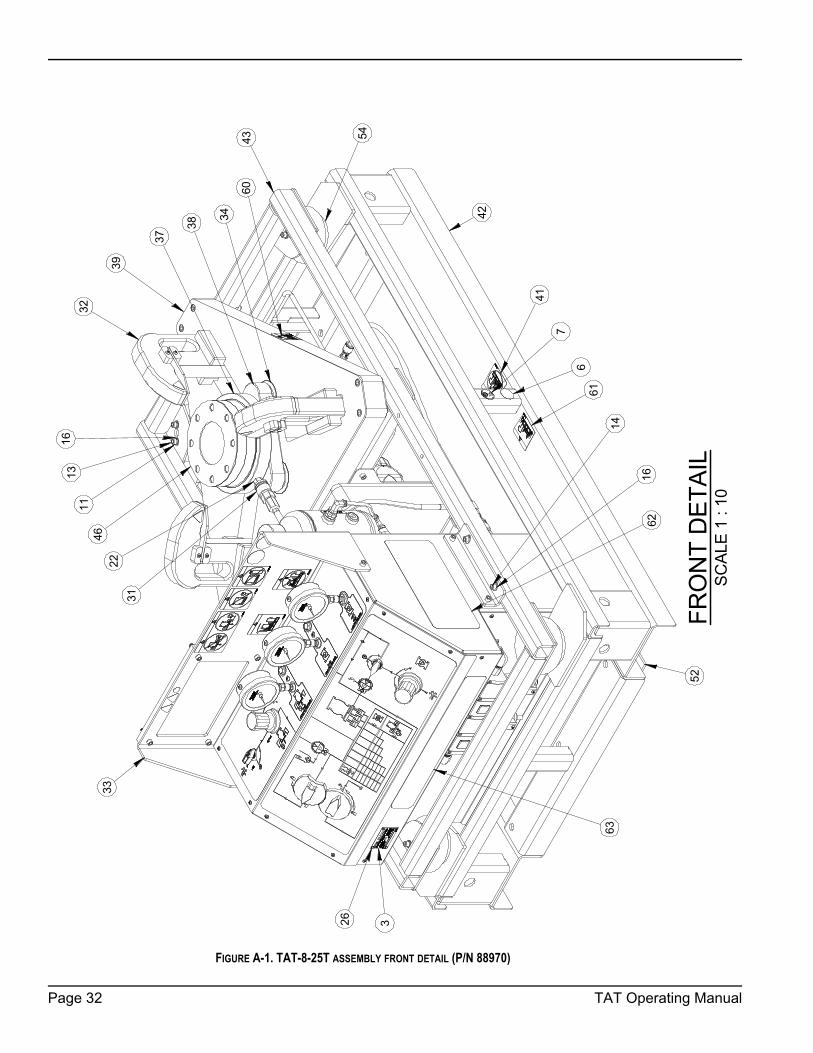
APPENDIX A ASSEMBLY DRAWINGSDrawing list
FIGURE A-1. TAT-8-25T ASSEMBLY FRONT DETAIL (P/N 88970) - - - - - - - - - - - - - - - - - - - - - - - - - - 32FIGURE A-2. TAT-8-25T ASSEMBLY BACK DETAIL (P/N 88970) - - - - - - - - - - - - - - - - - - - - - - - - - - - 33FIGURE A-3. TAT-8-25T ASSEMBLY EXPLODED VIEW DETAIL(P/N 88970) - - - - - - - - - - - - - - - - - - - - - - 34FIGURE A-4. TAT-8-25T ASSEMBLY PARTS LIST 1 (P/N 88970) - - - - - - - - - - - - - - - - - - - - - - - - - - 35FIGURE A-5. TAT-8-25T ASSEMBLY PARTS LIST 2 (P/N 88970) - - - - - - - - - - - - - - - - - - - - - - - - - - 36FIGURE A-6. CONSOLE ASSEMBLY FRONT DETAIL (P/N 89417) - - - - - - - - - - - - - - - - - - - - - - - - - - - 37FIGURE A-7. CONSOLE ASSEMBLY BACK DETAIL (P/N 89417) - - - - - - - - - - - - - - - - - - - - - - - - - - - 38FIGURE A-8. CONSOLE ASSEMBLY BACK DETAIL WITH PANEL REMOVED (P/N 89417) - - - - - - - - - - - - - - - - - 39FIGURE A-9. CONSOLE ASSEMBLY FRONT LABELS (P/N 89417) - - - - - - - - - - - - - - - - - - - - - - - - - - - 40FIGURE A-10. CONSOLE ASSEMBLY BACK LABELS (P/N 89417) - - - - - - - - - - - - - - - - - - - - - - - - - - - 41FIGURE A-11. CONSOLE ASSEMBLY PARTS LIST 1 (P/N 89417) - - - - - - - - - - - - - - - - - - - - - - - - - - - 42FIGURE A-12. CONSOLE ASSEMBLY PARTS LIST 2 (P/N 89417) - - - - - - - - - - - - - - - - - - - - - - - - - - - 43FIGURE A-13. CLAMP ARM ASSEMBLY (P/N 89416) - - - - - - - - - - - - - - - - - - - - - - - - - - - - - - - - 44TABLE A-1. O-RINGS KIT P/N 90025 - - - - - - - - - - - - - - - - - - - - - - - - - - - - - - - - - - - - - - - 45
Page 32 TAT Operating Manual
FIGURE A-1. TAT-8-25T ASSEMBLY FRONT DETAIL (P/N 88970)
FRO
NT
DET
AIL
SCAL
E 1
: 10
52
39
34
38
2231
37
26 3
7
6
41
16
14
33
54
1611
13
4632
43
42
61
62
60
63
P/N 90421, Rev. 1 Page 33
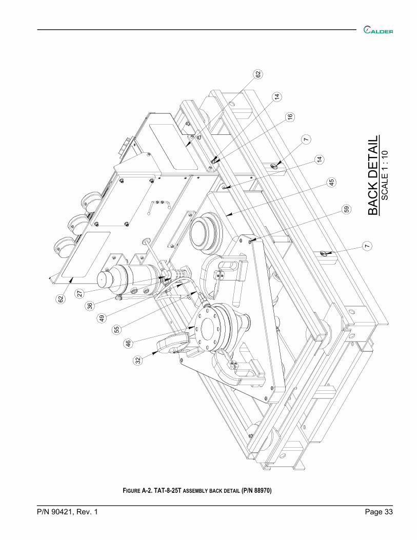
FIGURE A-2. TAT-8-25T ASSEMBLY BACK DETAIL (P/N 88970)
BAC
K D
ETAI
LSC
ALE
1 : 1
0
46
59
55
14
16
14
49
36
27
32
45
7
7
62
62

Page 34 TAT Operating Manual
FIGURE A-3. TAT-8-25T ASSEMBLY EXPLODED VIEW DETAIL(P/N 88970)
EXPL
OD
ED V
IEW
DET
AIL
SCAL
E 1
: 12
44
3627
4945
2231
28
3746 38 35 34 40

P/N 90421, Rev. 1 Page 35
FIGURE A-4. TAT-8-25T ASSEMBLY PARTS LIST 1 (P/N 88970)
PARTS LISTITEM QTY P/N: DESCRIPTION SCHEMATIC I.D.
1 6 10849 NUT 1/2-13 HEX SS 2 6 13243 (NOT SHOWN) WIRE TIE MEDIUM .14 X 8 3 1 29154 PLATE SERIAL YEAR MODEL CE 2.0 X 3.0 4 1 35692 FTG ELBOW 1/2 NPTM X 1/2 NPTF ST 90 DEG BRASS 5 77 56269 (NOT SHOWN) SLEEVE WELD COVER 1" DIA STRAIGHTLINE W/VELCRO CLOSURE 6 1 59033 LABEL WARNING - CENTER OF BALANCE 1.5" DIA 7 3 59039 LABEL WARNING LIFT POINT ROUND 1.5" 8 120 74933 (NOT SHOWN) FOAM STRIP 1/8 X 1 ADHESIVE BACKED BLACK 9 3 77489 FTG CONNECTOR 3/8NPTM X 3/8 TUBE 10 1 77492 FTG CONNECTOR PORT 3/8 TUBE 11 26 77523 WASHER 3/8 LOCK SS 12 6 78415 WASHER 1/2 FLTW SS 13 16 78427 SCREW 3/8-16 X 1 SHCS SS 14 10 78526 SCREW 3/8-16 X 1 1/4 SHCS SS 15 6 78665 WASHER 1/2 LOCW SS 16 32 78672 WASHER 3/8 FLTW SS 17 2 81917 FTG BARB 1/2 NPTM X 1/2 HOSE SWIVEL BRASS 18 4 82687 WASHER 5/16 FLTW SS 19 29 82847 HOSE LOW PRESSURE PUSH LOK 1/2 ID 20 1 82882 FTG TUBE ADAPTER 1/4 NPTF X 3/8 TUBE SS 21 10 83159 NUT 3/8-16 HEX SS 22 2 83456 FTG QUICK DISCONNECT MALE NIPPLE W/O CHECK VALVE 150000 PSI 1/4" MNPT 23 1 84083 FTG UNION CROSS 3/8 TUBE 24 1 85193 FTG ELBOW 1/4 NPTF SS 10K HEAVY WALL 25 3 85628 (NOT SHOWN) CABLE RESTRAINT HOSE WHIP .57 DIA X 11.81 LONG 26 4 87775 RIVET BLIND 1/8 DIA SS 316 27 1 88616 FTG ELBOW 1/4 NPTM X 1/4 NPTF STREET 90 DEG 15KSI 28 3 88740 SCREW 3/8-16 X 1-3/4 SHCS SS 316 29 3 88892 (NOT SHOWN) COLLAR RESTRAINT HOSE WHIP .47 TO .49 DIA 30 4 89144 SCREW 5/16-18 X 5/8 BHCS 18-8 SS 31 1 89160 FTG QUICK DISCONNECT FEMALE COUPLER W/ CHECK VALVE 15000 PSI 1/4" FNPT 32 3 89416 ASSY CLAMP ARM TAT-8-25T 33 1 89417 ASSY CONSOLE TAT-8-25T 34 3 89425 COLLAR THREADED CYLINDER 35 3 89426 CAP DOME CYLINDER 36 1 89427 DRAIN DIFFUSER 37 1 89428 SEAL PLATE TAT 38 1 89429 TOP PLATE TAT 39 1 89430 TABLE TOP TAT 40 3 89487 CYLINDER HYD 15 TON 4-1/8 STROKE SINGLE-ACTING C-01, C-02, C-03

Page 36 TAT Operating Manual
FIGURE A-5. TAT-8-25T ASSEMBLY PARTS LIST 2 (P/N 88970)
PARTS LISTITEM QTY P/N: DESCRIPTION SCHEMATIC I.D.
41 1 89499 LABEL CAUTION DO NOT LIFT WITH VALVE CLAMPED 42 1 89818 WELDMENT OUTER BASE FRAME TAT 43 1 89874 WELDMENT INNER BASE FRAME TAT 44 1 89888 SUPPORT TANK 16 GAL TAT 45 1 89991 TANK 16 GA 14.13 T" X 14.25 W X 20.38 L MODIFIED T-0146 1 89993 FLANGE SPACER 9 OD 47 1 89994 TUBE 3/8 TAT HYD CYL 1 48 1 89995 TUBE 3/8 TAT HYD CYL 2 49 2 90000 FTG BULKHEAD 1-1/2 NPTF X 1-1/2 NPTF X 4 L POLYPROPYLENE 50 1 90001 FTG REDUCER BUSHING 1-1/2 NPTM X 1/2 NPTF BRASS 51 1 90002 FTG NIPPLE 1-1/2 NPTM X 2.5 L HEX POLYPROPYLENE 52 6 90003 WASHER 3/4 X 4 W X 1/4 T SQUARE STEEL GAL 53 1 90004 FTG T STRAINER 1-1/2 NPTF 100 MESH POLYPROPYLENE F-0254 4 90005 SHOCK 6.0 DIA X 3 H 100 PSI AIRSTROKE ACTUATOR 55 1 90006 HOSE ASSY .23 ID 1/4 NPTM SS X 1/4 NPTM SS X 30.5 IN OAL 15KSI (6/2WL) 56 4 90020 FTG VALVE AIR FILL 1/4 NPTM 1-5/16 L BRASS 57 1 90021 (NOT SHOWN) STRAP CINCHING BUCKLE 2 W X 48 L POLY STEEL 58 1 90025 (NOT SHOWN) KIT TAT-8-25T SEAL PLATE 1.5" - 8" O-RINGS 59 6 90033 SCREW 1/2-13 X 5-1/2 SHCS SS 60 1 90533 LABEL CAUTION CLAMP ARM SHIPPING STRAP 61 1 90534 LABEL CAUTION FRAME TIE DOWN 62 3 90585 LABEL CALDER TURN AROUND TESTER TAT 6 X 13 63 1 90595 LABEL CALDER TURN AROUND TESTER TAT 2.75 X 19.5

P/N 90421, Rev. 1 Page 37
FIGURE A-6. CONSOLE ASSEMBLY FRONT DETAIL (P/N 89417)
3743
34
44
45
62
53
23
5
46
58
33
57
23
5
70
18
25
25
56
Page 38 TAT Operating Manual
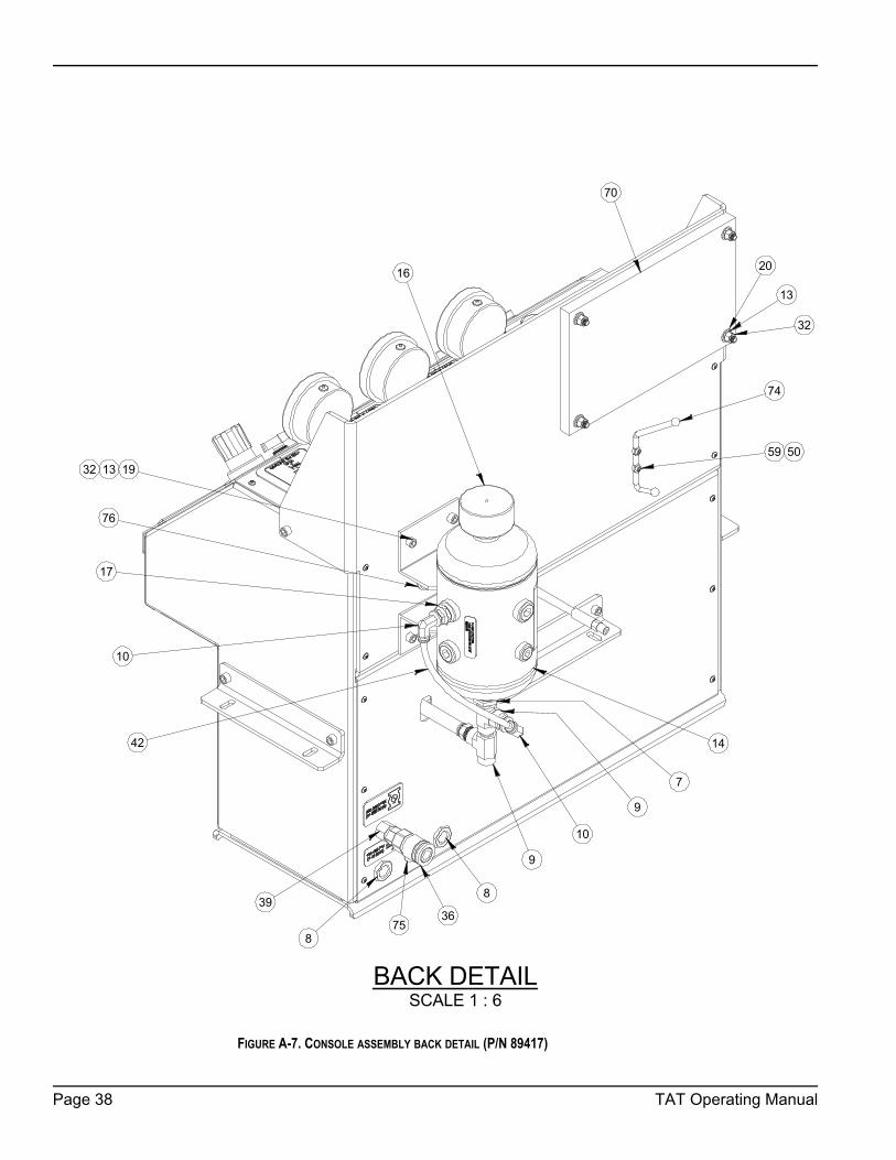
FIGURE A-7. CONSOLE ASSEMBLY BACK DETAIL (P/N 89417)
BACK DETAILSCALE 1 : 6
76
75
17
7
14
191332
70
13
20
32
59 50
74
9
9
8
8
3936
10
42
10
16

P/N 90421, Rev. 1 Page 39
FIGURE A-8. CONSOLE ASSEMBLY BACK DETAIL WITH PANEL REMOVED (P/N 89417)
PANEL REMOVED BACK DETAILSCALE 1 : 6
60
54
61
54
6
6
Page 40 TAT Operating Manual
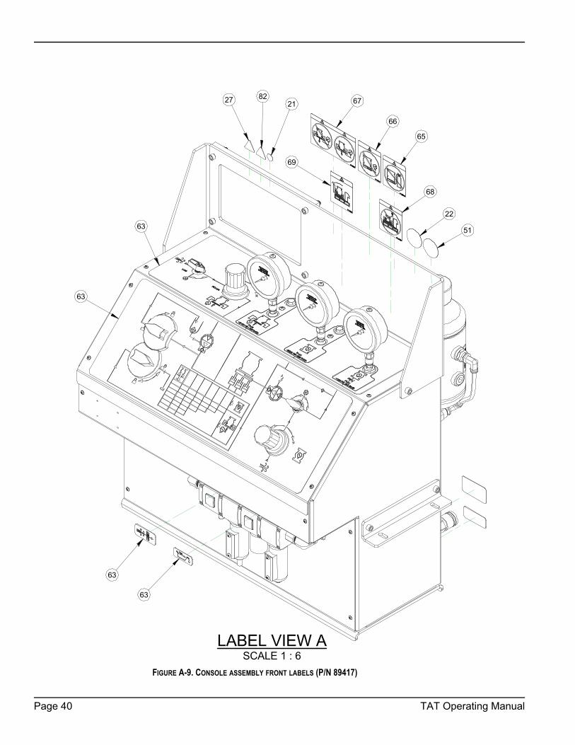
FIGURE A-9. CONSOLE ASSEMBLY FRONT LABELS (P/N 89417)
LABEL VIEW ASCALE 1 : 6
68
22
51
69
63
63
63
63
67
65
66
27 8221

P/N 90421, Rev. 1 Page 41
FIGURE A-10. CONSOLE ASSEMBLY BACK LABELS (P/N 89417)
LABEL VIEW BSCALE 1 : 6
63
63

Page 42 TAT Operating Manual
FIGURE A-11. CONSOLE ASSEMBLY PARTS LIST 1 (P/N 89417)
PARTS LISTITEM QTY P/N: DESCRIPTION SCHEMATIC I.D.
1 28 10704 HOSE PUSH LOK 801 1/4ID X 1/2OD 2 2 10705 FTG BARB 1/4 NPTM X 1/4 HOSE BRASS 3 1 12579 FTG PLUG 1/2 NPTM SOCKET 4 13 35692 FTG ELBOW 1/2 NPTM X 1/2 NPTF ST 90 DEG BRASS 5 2 77394 REGULATOR AIR 1/2 NPT 125 PSI PCV-02, PCV-046 2 77399 HIGH FLOW MUFFLER 3/4 NPTM COMPACT M-01, M-027 1 77403 STRAINER OIL 1 NPTM X 1/2 NPTF F-038 2 77421 FTG BULKHEAD 1/2 NPTF BRASS 9 3 77422 FTG TEE 1/2 NPTM X 1/2 NPTF MALE RUN TEE BRASS 10 2 77459 FTG ELBOW 1/2 NPTM X 3/8 TUBE PRESTOLOC SWIVEL 90 DEG BRASS 11 1 77460 FTG CONNECTOR 1/2 NPTM X 3/8 TUBE 12 3 77489 FTG CONNECTOR 3/8NPTM X 3/8 TUBE 13 12 77523 WASHER 3/8 LOCK SS 14 1 77788 RESERVOIR HYDRAULIC 1 GAL T-0215 2 77792 VALVE BALL 2 WAY 1/4 NPTF 10000 PSI V-05, V-0616 1 77804 FILLER BREATHER 3/4 NPTM F-0417 1 77877 FTG BUSHING BRASS 3/4 NPTM X 1/2 NPTF 18 1 77881 GAUGE PRESSURE 4 INCH DIA 160 PSI 1/4 NPTM BOTTOM MOUNT GLYCERIN FILLED P1-0119 4 78427 SCREW 3/8-16 X 1 SHCS SS 20 4 78672 WASHER 3/8 FLTW SS 21 1 79328 LABEL WARNING - CONSULT OPERATOR'S MANUAL GRAPHIC .75 DIA 22 1 81008 LABEL WEAR HEARING AND EYE PROTECTION 2.0 DIA 23 2 81787 MOUNT NUT REGULATOR PANEL 24 1 81791 FTG CHECK VALVE 1/4 FNPT 10 KSI SS 25 2 81794 GAUGE PRESSURE 4 IN DIA 10000 PSI 1/4" NPT BOTTOM MOUNT PI-02, PI-0326 18 81917 FTG BARB 1/2 NPTM X 1/2 HOSE SWIVEL BRASS 27 1 82144 LABEL WARNING - GENERAL DANGER GRAPHIC 1.30 X 1.13 28 2 82465 FTG BARB 1/4 NPTM X 1/4 HOSE 90 DEG ELBOW BRASS 29 237 82847 HOSE LOW PRESSURE PUSH LOK 1/2 ID 30 2 83105 FTG TUBE CONNECTOR 1/4 NPTM X 3/8 TUBE SUPER DUPLEX 31 1 83135 FTG BUSHING 1/2 NPTM x 1/4 NPTF BRASS 32 8 83159 NUT 3/8-16 HEX SS 33 1 83364 VALVE BALL 2-WAY 1/2 NPTF 1000 PSI BRASS V-0334 1 83984 FTG BULKHEAD 1/4 NPTF X 1/4 NPTF BRASS 35 2 84571 FTG TEE 1/4" NPT STREET BRASS 36 1 84796 FTG QUICK DISCONNECT FEMALE COUPLER W/ CHECK VALVE 15000 PSI 1/4 MNPT 37 2 84926 SCREW 1/4-20 X 3/8 BHSCS 18-8 SS 38 1 85192 FTG HEX NIPPLE 1/4 MNPT SS 10K HEAVY WALL 39 1 85232 FTG BULKHEAD 1/4 NPTF 15000 PSI 40 1 85259 ADAPTER 9/16 TYPE M X 1/4 MNPT STAINLESS 15 KSI 41 4 85271 SCREW 3/8-24 X 3/4 SHCS SS 42 11 85289 TUBING 3/8 OD X 1/4 ID POLYETHELYNE 43 6 85330 FTG PLUG 1/4 NPTM HEX HEAD 15 KSI

P/N 90421, Rev. 1 Page 43
FIGURE A-12. CONSOLE ASSEMBLY PARTS LIST 2 (P/N 89417)
PARTS LISTITEM QTY P/N: DESCRIPTION SCHEMATIC I.D.
44 3 87040 FTG TEST POINT 10 KSI 1/4 NPTM - M12 X 1.5 SS W/SS COVER 45 3 87041 FTG TEST POINT GAUGE ADAPTER 10 KSI 1/4 NPTF - M12 X 1.5 FEMALE SS 46 1 87225 VALVE DIVERTING 3-PORT 1/2 NPTF BRASS V-0247 4 87231 SCREW 10-32 X 1 BHSCS FLANGED SS316 48 1 87277 VALVE PRESSURE RELIEF AIR 150 PSI 1/4 NPTM PRV-0149 2 87422 MANIFOLD GAUGE HTC 10 KSI 50 2 87533 NUT 10-24 STDNYLOC SS 51 1 87593 LABEL WARNING - CONSULT OPERATORS MANUAL 2.0 DIA 52 1 87608 FTG ADAPTER 9/16 TYPE M X 1/2 NPTM STAINLESS 15 KSI 53 1 87836 ASSY AIR PREP UNIT & LUBRICATOR USV V-01, F-01,
PCV-01, L-0154 2 87838 REGULATOR 1/2 NPTF 7-125 PSIG W/BRACKET & PANEL NUT PCV-05, PCV-0355 2 88033 FTG NIPPLE 1/2 NPTM X 2-1/2 BRASS 56 1 88097 KNOB INTERLOCK TOP PLATE DRAIN VALVE 57 1 88665 KNOB INTERLOCK CLAMP RELEASE VALVE 58 4 88740 SCREW 3/8-16 X 1-3/4 SHCS SS 316 59 2 89117 SCREW 10-24 X 3/4 SHCS SS 60 1 89375 PUMP AIR DRIVEN 9700 PSI OIL OR WATER SERVICE P-0161 1 89377 PUMP AIR DRIVEN 5800 PSI OIL SERVICE P-0262 1 89418 CONSOLE TEST SYSTEM TAT-8-25T 63 6 89419 LABEL OVERLAY SET CLAMP FIXTURE TAT-8-25T 64 1 89478 FTG TEE STREET 1/4 MNPT X 1/4 FNPT X 1/4 FNPT SS 15 KSI 65 1 89496 LABEL WARNING NOT FOR HP GAS TESTING 66 1 89497 LABEL WARNING DO NOT EXCEED MAX RATING OF DUT 67 1 89498 LABEL WARNING DO NOT RELEASE CLAMP WHILE VALVE IS PRESSURIZED 68 1 89499 LABEL CAUTION DO NOT LIFT WITH VALVE CLAMPED 69 1 89500 LABEL WARNING TIP OVER HAZARD WITH ACTUATOR OVERHANGING 70 1 89988 SHEET HYGARD BR750 9.0" X 14.0" 71 1 89996 TUBE 3/8 TAT CONSOLE 1 72 1 89997 TUBE 3/8 TAT CONSOLE 2 73 1 89998 TUBE 3/8 SUPER DUPLEX TAT CONSOLE 3 74 1 90007 HOOK 1/2 W X 6-7/8 H X 3-3/4 D STEEL CHROME PLATED 75 1 90008 GROMMET LOCKING NYLON BLACK 3/4 ID X 1 PANEL HOLE 76 2 90009 GROMMET 3/4 ID X 1-13/16 OD 1/4 PANEL 77 1 90010 HOSE ASSY 1/4 ID 1/4 NPTM SS X 1/4 FEM JIC SS WITH 1/4 NPTM SS ADAPTER X 71 IN OAL
6KSI (4M6K)
78 1 90012 HOSE ASSY 1/4 ID 1/4 NPTM SS X 1/4 FEM JIC SS WITH 1/2 NPTM SS ADAPTER X 42 IN OAL 6KSI (4M6K)
79 1 90013 HOSE ASSY .23 ID 1/4 NPTM SS X 1/4 NPTM SS X 28 IN OAL 15KSI (6/2WL) 80 1 90014 HOSE ASSY .23 ID 1/4 NPTM SS X 9/16 FEM TYPE M SS X 34 IN OAL 15KSI (6/2WL) 81 1 90015 HOSE ASSY .23 ID 1/4 NPTM SS X 9/16 FEM TYPE M SS X 21 IN OAL 15KSI (6/2WL) 82 1 90160 LABEL WARNING - EXPLOSION RELEASE OF PRESSURE 1.30 X 1.13

Page 44 TAT Operating Manual
FIGURE A-13. CLAMP ARM ASSEMBLY (P/N 89416)
PARTS LISTDESCRIPTIONP/N:QTYITEM
WASHER 1/2 X 7/8 X .053 FLTW4233411LABEL WARNING - HAND CRUSH / FORCE FROM ABOVE GRAPHIC 1.13 TALL TRIANGLE YELLOW8090522SCREW 3/8-16 X 3 SHCS SS8266623SCREW 1/4-20 X 1-1/4 BHSCS SS8753444PLATE SHIM CLAMP ARM8942015BLOCK CONTACT CLAMP ARM8942116BLOCK SHIM GUIDE CLAMP ARM8942247ARM CLAMP MAIN8942318SHOE CLAMP ARM8942429SPRING PLUNGER 1/4-20 X .531 SS 2-4 LBS BALL89480210PIN DOWEL 1/2 DIA X 3 SS89481111SCREW 1/2-13 X 1-3/4 HHCS SS89482112SPACER 1/2 ID X 1 OD X 1 L ACETAL89483113PIN DOWEL 3/4 DIA X 3 SS89484114PIN DOWEL 1/8 DIA X 7/8 SS89489415
6
3
8
121
13
119
1410
4
715
5
2

P/N 90421, Rev. 1 Page 45
TABLE A-1. O-RINGS KIT P/N 90025
Part number
Description Quantity
77589 O-RING 3-5/8 ID X 3-7/8 OD X 1/8 W NITRILE 90 DUROMETER (2-239) 2
77590 O-RING 4-5/8 ID X 5 OD X 3/16 W NITRILE 90 DUROMETER (2-350) 2
78456 O-RING 5-5/8 ID X 6 OD X 3/16 W NITRILE 90 DUROMETER (2-358) 2
78457 O-RING 6-3/4 ID X 7-1/8 OD X 3/16 W NITRILE 90 DUROMETER (2-364) 2
78458 O-RING 8-3/4 ID X 9-1/8 OD X 3/16 W NITRILE 90 DUROMETER (2-372) 2
90026 O-RING 1-7/8 ID X 2-1/8 OD X 1/8 W NITRILE 90 DUROMETER (2-225) 2
90027 O-RING 2-5/8 ID X 2-7/8 OD X 1/8 W NITRILE 90 DUROMETER (2-231) 2

Page 46 TAT Operating Manual
This page intentionally left blank

P/N 90421, Rev. 1 Page 47
APPENDIX B SCHEMATICS
FIGURE B-1. SCHEMATIC (P/N 90024)

Page 48 TAT Operating Manual
This page intentionally left blank

P/N 90421, Rev. 1 Page 49
APPENDIX C SDSSafety Data Sheet list
Conoco AW 32 and 46 Unax . . . . . . . . . . . . . . . . . . . . . . . . . . . . . . . . . 50

Page 50 TAT Operating Manual
1. PRODUCT AND COMPANY IDENTIFICATION
2. COMPOSITION/INFORMATION ON INGREDIENTS
EMERGENCY OVERVIEW24 Hour Emergency Telephone Numbers:Spill, Leak, Fire or AccidentCall CHEMTRECNorth America: (800)424-9300Others: (703)527-3887 (collect)
Physical Hazards/Precautionary Measures: Keep away from all sources of ignition.
Not Established
Agency Type
Zinc CompoundCAS# Proprietary
<1
% WEIGHTHAZARDOUS COMPONENTS EXPOSURE GUIDELINE
California Poison Control System: (800) 356-3129
Limits
MATERIAL SAFETY DATA SHEET76 Unax AW 32, 46, 68
(MSDS: 722330)
Health Hazards/Precautionary Measures:
NFPA Hazard Class: HMIS Hazard Class
Physical form: LiquidOdor: Mild petroleum
Appearance: Clear and bright
Health: 1 (Slight) Health: 1 (Slight)Flammability:1 (Slight) Flammability: 1 (Slight)Reactivity: 0 (Least) Physical Hazard: 0 (Least)
Product Name: 76 Unax AW 32, 46, 68Product Code: 4641032000, 4642046000, 4643068000Synonyms: 76 Unax AW 32
76 Unax AW 4676 Unax AW 68
Intended Use: Industrial oilChemical Family: Petroleum hydrocarbon
Responsible Party: 76 LubricantsA Division of ConocoPhillips600 N. Dairy AshfordHouston, TX 77079-1175
For Additional MSDSs 800-762-0942Technical Information: 800-435-7761The intended use of this product is indicated above. If any additional use is known, please contact us at the Technical Information number listed.
Avoid contact with eyes, skin and clothing. Wash thoroughly afterhandling.
Page 1 of 7

P/N 90421, Rev. 1 Page 51
3. HAZARDS IDENTIFICATION
Inhalation (Breathing): No information available. Studies by other exposure routes suggesta low degree of toxicity by inhalation.
Skin: Contact may cause mild skin irritation including redness, and a burning sensation. Prolonged orrepeated contact can worsen irritation by causing drying and cracking of the skin leading to dermatitis(inflammation). No harmful effects from skin absorption are expected.
Eye: Contact may cause mild eye irritation including stinging, watering, and redness.
Ingestion (Swallowing): No harmful effects expected from ingestion.
Signs and Symptoms: Effects of overexposure may include irritation of the nose and throat,irritation of the digestive tract, nausea and diarrhea.
Potential Health Effects:
Inadequate evidence available to evaluate the cancer hazard of this material. See Section11 for carcinogenicity information of individual components, if any.
Cancer:
Target Organs: No data available for this material.
Developmental: No data available for this material.
OTHER COMPONENTS
Limits Agency Type
Lubricant Base Oil (Petroleum)
Additives
>99
<1
(See: Oil Mist, If Generated)
Not Established
The base oil for this product can be a mixture of any of the following highly refined petroleum streams:CAS 64741-88-4; CAS 64741-89-5; CAS 64741-96-4; CAS 64741-97-5; CAS 64742-01-4; CAS 64742-52-5; CAS64742-53-6; CAS 64742-54-7; CAS 64742-55-8; CAS 64742-56-9; CAS 64742-57-0; CAS 64742-62-7; CAS64742-63-8; CAS 64742-65-0; CAS 72623-85-9; CAS 72623-86-0; CAS 72623-87-1
Note: State, local or other agencies or advisory groups may have established more stringent limits.Consult an industrial hygienist or similar professional, or your local agencies, for further information.
1%=10,000 PPM.
All components are listed on the TSCA inventory.
% WEIGHT EXPOSURE GUIDELINE
CAS# Various
CAS# Proprietary
REFERENCE
Limits Agency Type
Oil Mist, If Generated 5 mg/m3 ACGIH TWA 10 mg/m3 ACGIH STEL 5 mg/m3 OSHA TWA 2500 mg/m3 NIOSH IDLH 5 mg/m3 NOHSC TWA
EXPOSURE GUIDELINE
CAS# None
(MSDS: 722330)
___________________________________________________________________________________________
____________________________________________________________________________________________
Page 2 of 7

Page 52 TAT Operating Manual
Pre-Existing Medical Conditions: Conditions aggravated by exposure may include skindisorders.
4. FIRST AID MEASURES
Eye: If irritation or redness develops, move victim away from exposure and into fresh air. Flush eyeswith clean water. If symptoms persist, seek medical attention.
Skin: Wipe material from skin and remove contaminated shoes and clothing. Cleanse affected area(s)thoroughly by washing with mild soap and water and, if necessary, a waterless skin cleanser. Ifirritation or redness develops and persists, seek medical attention.
Inhalation (Breathing): If respiratory symptoms develop, move victim away from source of exposure and intofresh air. If symptoms persist, seek medical attention. If victim is not breathing, clear airway and immediatelybegin artificial respiration. If breathing difficulties develop, oxygen should be administered by qualifiedpersonnel. Seek immediate medical attention.
Ingestion (Swallowing): First aid is not normally required; however, if swallowed and symptoms develop, seekmedical attention.
Note To Physicians: High-pressure hydrocarbon injection injuries may produce substantialnecrosis of underlying tissue despite an innocuous appearing external wound. Often these injuriesrequire extensive emergency surgical debridement and all injuries should be evaluated by aspecialist in order to assess the extent of injury.
5. FIRE FIGHTING MEASURES
Fire Fighting Instructions: For fires beyond the incipient stage, emergency responders in the immediate hazardarea should wear bunker gear. When the potential chemical hazard is unknown, in enclosed or confined spaces, orwhen explicitly required by DOT, a self contained breathing apparatus should be worn. In addition, wear otherappropriate protective equipment as conditions warrant (see Section 8).
Isolate immediate hazard area, keep unauthorized personnel out. Stop spill/release if it can be done with minimalrisk. Move undamaged containers from immediate hazard area if it can be done with minimal risk.
Water spray may be useful in minimizing or dispersing vapors and to protect personnel. Cool equipment exposed tofire with water, if it can be done with minimal risk. Avoid spreading burning liquid with water used for coolingpurposes.
6. ACCIDENTAL RELEASE MEASURES
This material may burn, but will not ignite readily. Keep all sources of ignition away from spill/release. Stayupwind and away from spill/release. Notify persons down wind of the spill/release, isolate immediate hazard areaand keep unauthorized personnel out. Stop spill/release if it can be done with minimal risk. Wear appropriateprotective equipment including respiratory protection as conditions warrant (see Section 8).
LEL/UEL%: No DataAutoignition Temperature: No Data
Flammable Properties: Flash Point: >384°F/>196°C (COC) Not applicableOSHA Flammability Class:
(MSDS: 722330)
Unusual Fire & Explosion Hazards:
Extinguishing Media: Dry chemical, carbon dioxide, foam, or water spray is recommended. Water or foam maycause frothing of materials heated above 212°F. Carbon dioxide can displace oxygen. Use caution when applyingcarbon dioxide in confined spaces.
This material may burn, but will not ignite readily. If container is not properlycooled, it can rupture in the heat of a fire.
Page 3 of 7

P/N 90421, Rev. 1 Page 53
Prevent spilled material from entering sewers, storm drains, other unauthorized drainage systems, and naturalwaterways. Dike far ahead of spill for later recovery or disposal. Spilled material may be absorbed into anappropriate absorbent material.
Notify fire authorities and appropriate federal, state, and local agencies. Immediate cleanup of any spill isrecommended. If spill of any amount is made into or upon navigable waters, the contiguous zone, or adjoiningshorelines, notify the National Response Center (phone number 800-424-8802).
7. HANDLING AND STORAGEHandling:
Storage:
Do not enter confined spaces such as tanks or pits without following proper entryprocedures such as ASTM D-4276 and 29CFR 1910.146. The use of appropriate respiratory protection is advisedwhen concentrations exceed any established exposure limits (see Sections 2 and 8).
Do not wear contaminated clothing or shoes. Use good personal hygiene practices.
High pressure injection of hydrocarbon fuels, hydraulic oils or greases under the skin may have seriousconsequences even though no symptoms or injury may be apparent. This can happen accidentally when usinghigh pressure equipment such as high pressure grease guns, fuel injection apparatus or from pinhole leaks intubing of high pressure hydraulic oil equipment.
"Empty" containers retain residue and may be dangerous. Do not pressurize, cut, weld, braze, solder, drill,grind, or expose such containers to heat, flame, sparks, or other sources of ignition. They may explode andcause injury or death. "Empty" drums should be completely drained, properly bunged, and promptly shipped tothe supplier or a drum reconditioner. All containers should be disposed of in an environmentally safemanner and in accordance with governmental regulations.
Before working on or in tanks which contain or have contained this material, refer to OSHA regulations, ANSIZ49.1 and other references pertaining to cleaning, repairing, welding, or other contemplated operations.
Keep container(s) tightly closed. Use and store this material in cool, dry, well-ventilatedareas away from heat and all sources of ignition. Store only in approved containers. Keep away from anyincompatible material (see Section 10). Protect container(s) against physical damage.
Engineering controls:
Respiratory:
Personal Protective Equipment (PPE):
If current ventilation practices are not adequate to maintain airborne concentrations belowthe established exposure limits (see Section 2), additional engineering controls may be required.
A NIOSH certified air purifying respirator with a Type 95 (R or P) particulatefilter may be used under conditions where airborne concentrations are expected to exceedexposure limits (see Section 2).
Protection provided by air purifying respirators is limited (see manufacturer's respiratorselection guide). Use a NIOSH approved self-contained breathing apparatus (SCBA) orequivalent operated in a pressure demand or other positive pressure mode if there ispotential for an uncontrolled release, exposure levels are not known, or any othercircumstances where air purifying respirators may not provide adequate protection. Arespiratory protection program that meets OSHA's 29 CFR 1910.134 and ANSI Z88.2requirements must be followed whenever workplace conditions warrant a respirator's use.
Skin:
Eye/Face:
The use of gloves impervious to the specific material handled is advised to prevent skincontact and possible irritation (see manufacturers literature for information onpermeability).
Approved eye protection to safeguard against potential eye contact, irritation, orinjury is recommended. Depending on conditions of use, a face shield may be necessary.
8. EXPOSURE CONTROLS/PERSONAL PROTECTION
(MSDS: 722330) Page 4 of 7

Page 54 TAT Operating Manual
Other Protective Equipment: A source of clean water should be available in the workarea for flushing eyes and skin. Impervious clothing should be worn as needed.
Suggestions for the use of specific protective materials are based on readily available publisheddata. Users should check with specific manufacturers to confirm the performance of their products.
9. PHYSICAL AND CHEMICAL PROPERTIES
10. STABILITY AND REACTIVITY
Stability:
Conditions To Avoid:
Hazardous Decomposition Products:
Hazardous Polymerization:
Extended exposure to high temperatures can cause decomposition.
Stable under normal ambient and anticipated storage and handling conditions of temperature andpressure.
Combustion can yield carbon, nitrogen, sulfur,phosphorus, and zinc oxides. Will not occur.
11. TOXICOLOGICAL INFORMATIONLubricant Base Oil (Petroleum) (CAS# Various)
Carcinogenicity: The petroleum base oils contained in this product have been highly refined bya variety of processes including solvent extraction, hydrotreating, and dewaxing to remove aromatics andimprove performance characteristics. None of the oils used are listed as a carcinogen by NTP, IARC, orOSHA.
Appearance: Clear and brightPhysical State: LiquidOdor: Mild petroleumpH: Not applicable Vapor Pressure (mm Hg): <1Vapor Density (air=1): >1Boiling Point/Range: No DataFreezing/Melting Point: <-27°F / <-33°CSolubility in Water: Negligible Specific Gravity: 0.855-0.871 Percent Volatile: Negligible Evaporation Rate (nBuAc=1): NegligibleViscosity: 22-68 cSt @ 40°C / 4.3-8.7 cSt @ 100°CBulk Density: 7.13-7.26 lb/galFlash Point: >384°F / >196°C (COC)
No DataFlammable/Explosive Limits (%):
Note: Unless otherwise stated, values are determined at 20°C (68°F) and 760 mm Hg (1 atm).
12. ECOLOGICAL INFORMATION
(MSDS: 722330)
Materials to Avoid (Incompatible Materials):
Not evaluated at this time
Avoid contact with strong oxidizingagents.
Page 5 of 7

P/N 90421, Rev. 1 Page 55
13. DISPOSAL CONSIDERATIONSThis material under most intended uses would become used oil due to contamination by physical or chemicalimpurities. RECYCLE ALL USED OIL. While being recycled, used oil is regulated by 40 CFR 279. Use resulting inchemical or physical change or contamination may also subject it to regulation as hazardous waste. Underfederal regulations, used oil is a solid waste managed under 40 CFR 279. However, in California, used oil ismanaged as hazardous waste until tested to show it is not hazardous. Consult state and local regulationsregarding the proper handling of used oil. In the case of used oil, the intent to discard it may cause the usedoil to be regulated as hazardous waste.
Contents should be completely used and containers emptied prior to discard. Rinsate may be considered a RCRAhazardous waste and must be disposed of with care and in compliance with federal, state and local regulations.Large empty containers, such as drums, should be returned to the distributor or a drum reconditioner. To assureproper disposal of small empty containers, consult with state and local regulations and disposal authorities.
14. TRANSPORT INFORMATION
16. OTHER INFORMATIONIssue Date: 02/06/03
Component CAS Number Weight %Zinc Compound Proprietary <1
SARA 313 and 40 CFR 372:This material contains the following chemicals subject to the reporting requirements of SARA 313 and 40CFR 372:
Warning: This material contains the following chemicals which are known to the State of California to cause cancer,birth defects or other reproductive harm, and are subject to the requirements of California Proposition 65 (CA Health& Safety Code Section 25249.5): --None Known--
EPA (CERCLA) Reportable Quantity: --None--
EPA SARA 311/312 (Title III Hazard Categories):
15. REGULATORY INFORMATION
California Proposition 65:
Carcinogen Identification:
Canada - Domestic Substances List:WHMIS Class:
(MSDS: 722330)
DOT Shipping Description:
This material has not been identified as a carcinogen by NTP, IARC, or OSHA. See Section 11 forcarcinogenicity information of individual components, if any.
Listed
Acute Health: NoChronic Health: NoFire Hazard: NoPressure Hazard: NoReactive Hazard: No
Not regulated This product has been classified in accordance with the hazard criteria of the Controlled Products Regulations(CPR) and the MSDS contains all the information required by the CPR.
Not classified as hazardous
Page 6 of 7

Page 56 TAT Operating Manual
Disclaimer of Expressed and Implied Warranties:The information presented in this Material Safety Data Sheet is based on data believed to be accurate as of the date this Material Safety DataSheet was prepared. HOWEVER, NO WARRANTY OF MERCHANTABILITY, FITNESS FOR ANY PARTICULAR PURPOSE, OR ANY OTHERWARRANTY IS EXPRESSED OR IS TO BE IMPLIED REGARDING THE ACCURACY OR COMPLETENESS OF THE INFORMATIONPROVIDED ABOVE, THE RESULTS TO BE OBTAINED FROM THE USE OF THIS INFORMATION OR THE PRODUCT, THE SAFETY OFTHIS PRODUCT, OR THE HAZARDS RELATED TO ITS USE. No responsibility is assumed for any damage or injury resulting from abnormaluse or from any failure to adhere to recommended practices. The information provided above, and the product, are furnished on the conditionthat the person receiving them shall make their own determination as to the suitability of the product for their particular purpose and on thecondition that they assume the risk of their use. In addition, no authorization is given nor implied to practice any patented invention without alicense.
Previous Issue Date: 01/01/02Product Code: 4641032000, 4642046000, 4643068000Revised Sections: New FormatPrevious Product Code: 4641032000MSDS Number: 722330
(MSDS: 722330)
Status: Final
Page 7 of 7

