tardir/mig/a329985 - defense technical information center price code 20. limitation of abstract ......
TRANSCRIPT
WL-TR-97-3092
ADVANCED FIRE SUPPRESSION TECHNOLOGY (AFST) RESEARCH AND DEVELOPMENT PROGRAM
M.A. WILSON J.D. MORAN
OLIN AEROSPACE CORPORATION 11441 WILLOWS ROAD N.E. P.O. BOX 97009 REDMOND, WA 98073-9709
APRIL 1997
FINAL REPORT FOR 08/31/93-04/28/97
APPROVED FOR PUBLIC RELEASE; DISTRIBUTION IS UNLIMITED.
19971008 031 FLIGHT DYNAMICS DIRECTORATE WRIGHT LABORATORY AIR FORCE MATERIEL COMMAND WRIGHT PATTERSON AFB OH 45433-7562
[33TXO QUALEF? EfGFiani) g

NOTICE
USING GOVERNMENT DRAWINGS, SPECIFICATIONS, OR OTHER DATA INCLUDED IN THIS DOCUMENT FOR ANY PURPOSE OTHER THAN GOVERNMENT PROCUREMENT DOES NOT IN ANY WAY OBLIGATE THE US GOVERNMENT. THE FACT THAT THE GOVERNMENT FORMULATED OR SUPPLIED THE DRAWINGS, SPECIFICATIONS, OR OTHER DATA DOES NOT LICENSE THE HOLDER OR ANY OTHER PERSON OR CORPORATION; OR CONVEY ANY RIGHTS OR PERMISSION TO MANUFACTURE, USE OF SELL ANY PATENTED INVENTION THAT MAY RELATE TO THEM.
THIS REPORT IS RELEASABLE TO THE NATIONAL TECHNICAL INFORMATION SERVICE (NTIS). AT NTIS, IT WILL BE AVAILABLE TO THE GENERAL PUBLIC, INCLUDING FOREIGN NATIONS.
THIS TECHNICAL REPORT HAS BEEN REVIEWED AND IS APPROVED FOR PUBLICATION.
!antain Mark A Gillesnie / Ralüh J. Seeelman Captain Mark A. Gillespie ' Ralph. Project Engineer, Technology Group Chief Survivability and Safety Branch Survivability and Safety Branch
Richard E. Colclougt Chief, Vehicle Subsystems Division Flight Dynamics Directorate Wright Laboratory
IF YOUR ADDRESS HAS CHANGED, IF YOU WISH TO BE REMOVED FROM OUR MAILING LIST, OR IF THE ADDRESSEE IS NO LONGER EMPLOYED BY YOUR ORGANIZATION, PLEASE NOTIFY WL/FIVS WRIGHT-PATTERSON AFB, OH 45433- 7605 TO HELP MAINTAIN A CURRENT MAILING LIST.
Do not return copies of this report unless contractual obligations or notice on a specified document requires its return.

REPORT DOCUMENTATION PAGE Form Approved
OMB No. 0704-0188
Pubfc reporting burden for this coitection of information is .stated to average 1 hour per response, including .1» tin. for -.»»wins instructions, se.rch.ng ei sting data ' «» ;r^,7wa"d
hi^ ™11 s S?r£.,^SaTntaaTn the collection of informal« Send comments regarding this burden estimate or an» other aspect of this collection of information «ludmg suggestions for <f^J%^.^!^"%^ SemCeS' °°K""" Operations and Reports, 1215 Jefferson Davis High*.« Suite 1204, Arlington, VA 222024302, and to the Office of Management and Budget. Paperwork Reduction Project (0704-01881, Washington, OC 20503.
1. AGENCY USE ONLY (Leave blank/ 2. REPORT DATE
April 1997
3. REPORT TYPE AND DATES COVERED
Final Report 08/31/93 - 04/28/97 4. TITLE AND SUBTITLE
Advanced Fire Suppression Technology (AFST) Research and Development Program
6. AUTHOR(S)
M.A. Wilson and J.D. Moran
7. PERFORMING ORGANIZATION NAME(S) AND ADDRESS(ES)
Olin Aerospace Corporation 11441 Willows Road N.E. P.O. Box 97009 Redmond, WA 98073-9709
9. SPONSORING/MONITORING AGENCY NAME(S) AND ADDRESS(ES)
Flight Dynamics Directorate Air Force Research Laboratory Air Force Materiel Command Wright-Patterson AFB, OH 45433-7605 POC; CAPT. MARK A. GILLESPIE, WL/FIVS (937) 255-7125
11. SUPPLEMENTARY NOTES
5. FUNDING NUMBERS
C F33615-93-C-3404 PE 62201F PR 2402 TA 02 WU TU
8. PERFORMING ORGANIZATION REPORT NUMBER
10. SPONSORING/MONITORING AGENCY REPORT NUMBER
WL-TR-97-3092
INTERIM REPORT WAS SUBMITTED IN 1995 AS WL-TR-94-3133, ADA 301-809
12a. DISTRIBUTION AVAILABILITY STATEMENT
APPROVED FOR PUBLIC RELEASE; DISTRIBUTION UNLIMITED
12b. DISTRIBUTION CODE
13. ABSTRACT (Maximum 200 words} Halon 1301 has been widely used in aircraft fire suppression systems because of its ability to efficiently extinguish fires. Unfortunately, halon production was banned in 1994 because it is an ozone depleting substance. The ban on halon production has created a need for alternative fire suppression technologies in both the military and civilian aircraft industries. Solid Propellant Gas Generators (SPGG) is a viable alternative to halon for in-flight fire suppression. SPGG relies on the
controlled burning of solid reactants to produce inert gases (H20, C02, and N2) that can be used for fire suppression and it was developed from technology originally applied in automotive airbag devices. The testing discussed in this report is based on the results and conclusions derived from previous testing. SPGG devices and hybrid systems (SPGG used to pressurize a liquid fire extinguishant such as H20 or FM200) were tested against three fire conditions. The test results revealed that SPGG and hybrid systems were effective in extinguishing the fire conditions, but performance was slightly worse than HFC-125 on an agent mass comparison. Further testing and development of the gas generator is required before it is fully understood and can be considered mature.
14. SUBJECT TERMS
DRY BAY, ENGINE NACELLE, FIRE SUPPRESSION, AIRBAG, SOLID PROPELLANT, GAS GENERATOR
17. SECURITY CLASSIFICATION OF REPORT
UNCLASSIFIED
18. SECURITY CLASSIFICATION OF THIS PAGE
UNCLASSIFIED
19. SECURITY CLASSIFICATION OF ABSTRACT
UNCLASSIFIED
15. NUMBER OF PAGES
32 16. PRICE CODE
20. LIMITATION OF ABSTRACT
SAR Standard Form 298 {Rev. 2-89) (EG) Prescribed by ANSI Std. 233.18 Designed using Perform Pro, WHSIDIOR, Oct 94

Contents
Foreword iv
Summary 1 Introduction 3 Test Article Description 4
Propellant 4
Gas Generator/Manifold 5 Engine Nacelle Simulator 5
Discussion of Test Results 12 Run No. 13 Results 12 Run No. 14 Results 16 Run No. 30 Results 19
Conclusions and Recommendations 23 Conclusions 23 Recommendations 23
Figures
VI 1 Operational Schematic of Solid Propellant Gas Generator 2 Shipset of 747 Hybrid Slide Inflation Generators yii 3 Operational Schematic of Hybrid Gas Generator .Y1X1
4 Refurbishable Fire Suppression Gas Generator Assembly 6 5 Refurbishable Fire Suppression Hybrid Gas Generator Assembly 7 6 FSO1-40 Propellant Canister 8 7 Collection/Distribution Manifold for Gas Generator Testing 9 8 Fire Suppression Agent Distribution System 10 9 WPAFB Engine Nacelle Simulator 11 10 Test Series No. 13 Configuration 14 11 Test Series No. 14 Configuration 17 12 Test Series No. 30 Configuration 20 13 Modified Test Series No. 30 Configuration 22
Tables
1 RRC FS01-40 Propellant Properties 4 2 Engine Nacelle Simulator Configuration for Phase II Testing 5 3 Series No 13 Test Results 15 4 SeriesNo 14 Test Results 18 5 Series No 30 Test Results 21
in

FOREWORD
This report is focused on a series of tests run at Wright Patterson AFB in July of 1995 as a follow on to work previously done and summarized in Document No. 95-R-1922. The previous testing, defined as Phase I, demonstrated the feasibility of using OAC gas generator technology in aircraft fire suppression systems. The work discussed in this report, defined as Phase U, was to use the results and conclusions of the earlier testing to further refine and optimize gas generator configuration and agent discharge location within the test fixture. Due to funding limitations the second phase of the work was limited to testing within the simulated engine nacelle.
Fire suppression systems on military and commercial aircraft currently all use Halon-1301 which, along with chlorofluorocarbons (CFC's) and other halide substituted hydrocarbons have ozone depleting characteristics. As a consequence of an international treaty severely curtailing the production of CFC's over the next few years and concern on the part of government agencies and the commercial sector over the ozone layer and other environmental issues, production of Halon- 1301, CFC's and other ozone depleting compounds have or soon will be discontinued. The Air Force is using its on-hand inventory of Halon-1301 while actively seeking a replacement system which it hopes to have in place at the end of the decade. Unfortunately, most replacement systems currently under evaluation are much heavier and bulkier for equivalent protection, requiring significant retrofit costs, while reducing aircraft payload and increasing fuel usage.
OAC's solid propellant systems, which are a spin-off of automotive airbag technology, use an advanced nonazide propellant technology that has been shown to be an effective Halon-1301 alternative. These systems produce conventional fire suppression gases such as nitrogen, carbon dioxide and water vapor at high temperatures which make them effective fire suppressants. Figure 1 contains a simplified illustration of a solid propellant gas generator with time/pressure plots of its operation. The device is activated by an electrical signal, which functions an electrical initiator inside the gas generator, providing pressure, heat and hot particles thereby igniting the solid propellant grain or grains. As the propellant bums the gases rapidly pressurize the gas generator. At a predetermined pressure, a sealed burst disk ruptures, allowing gas to flow out of the gas generator. This expelled gas then may be used to suppress a fire, or when characterizing gas generator performance used to pressurize a sealed tank (yielding a time/pressure curve as in Figure 1). The gas generator pressure profile is controlled by the ratio of the burning propellant surface area to the orifice flow area. An optional filter can be incorporated to remove any paniculate evolved during the combustion process. The filter also reduces the propellant exhaust gas temperature due to its high surface area in contact with the propellant gas.
Hybrid gas generators shown in Figure 2 have also been identified as a Halon-1301 alternative. Figure 3 contains a simplified illustration of a hybrid gas generator with time/pressure plots of its operation. The hybrid gas generator consists of a solid propellant gas generator which discharges into a solid, liquid or vapor agent. The agent is pressurized and heated to a liquid or vapor state and then discharged at a predetermined pressure via a burst disk. The gas temperature of a hybrid gas generator is significantly cooler than that of a solid propellant-only gas generator due to the heat absorbed by the hybrid agent Vaporization of hybrid agents or the heating of them combined with expulsion from the system by hot gas generant gases in this type of system allows chemicals not previously considered as fire suppressants due low volatility and difficulty of dispersion to be re- examined. Possible candidates as hybrid agents include water or aqueous solutions, carbon dioxide and fluorocarbons.
IV

Phase I testing included tests with solid propellant-only gas generators and hybrid units with water, FM-200 (C3HF7), PFC-614 (C6F14), and carbon dioxide (CO?). One of the recommendations of that work was to eliminate carbon dioxide from consideration for use in future testing of the hybrid unit due to its poor packing efficiency (twice the volume requirement as FM- 200). Therefore, no tests were run with carbon dioxide in Phase II. However, FM-200 and water both yielded promising results in Phase I and were therefore tested further in Phase n.

SOLID PROPELLANT
PRESSURE VESSEL
INITIATOR
FILTER \y (OPTIONAL)
FLOW CONTROL)
ORIFICE ( TIME
BURST DISK
SEALED OR VENTED
ENCLOSURE
LU CC Z) CO o _1 Ü z LU
111 cr ID CO CO
QCC LU a.
< LU CO
TIME
Figure 1. Operational Schematic of Solid Propellant Gas Generator
VI

C CO
c S
. C
s ä .2? a
fcd
>>
r- ,^- r-
«5 a, 00
VI1

ft INITIATOR
SOLID PROPELLANT
PRESSURE VESSEL
ZX FILTER \y (OPTIONAL)
FLOW CONTROL)
ORIFICE
TIME
(
HYBRID PRESSURE
VESSEL
TIME
BURST DISK
SEALED OR VENTED
ENCLOSURE
UJ
§UJ
o z UJ UJ QCC UJ 0.
< UJ CO
TIME
Figure 3. Operational Schematic of Hybrid Gas Generator System
viu

SUMMARY
Phase II test activities evaluated several gas generator configurations against three engine nacelle fire scenarios (runs). Gas generator configurations included solid propellant-only units and hybrid units in which the solid propellant gas generator pressurizes and discharges a secondary agent Heavyweight refurbishable generator hardware was used. Phase I testing demonstrated that agent discharge at top, side, and bottom ports was more effective than discharge at a single location. Phase II tests were set up with this same multi-port agent discharge arrangement. Phase I testing was conducted with the fire suppression gas generators located at each agent discharge port. A significant change was made for Phase II testing by locating the gas generators in a distribution manifold approximately 40 feet from the nacelle discharge ports. Connecting lines carried die agent from this manifold to the discharge ports.
The Run No. 13 configuration used 83282 hydraulic fluid as fuel at a high internal airflow rate and is outlined in Table 3. In this series, best results were obtained with closely spaced sequential firing of multiple gas generators. Two gas generators were the minimum number required to put out the fire, but it relit very soon thereafter. Three gas generators timed to fire in 0.5 seconds or less yielded better success with longer times to relight after extinguishment. However, it took three gas generators firing in a sequence up to 0.3 seconds and 1.32 pounds of water in a hybrid configuration to completely extinguish the fire without relight This is a total agent weight of 4.32 lbm which is 1.57 times the amount of FE-25 required in tests previously conducted by Wright Patterson for this test configuration.
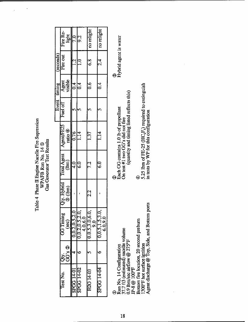
The Run No. 14 configuration used JP-8 as fuel at a low internal airflow rate and is outlined in Table 4. In this configuration at least four gas generators with the firing sequence spread out over several seconds were required to put out the fire. It required six gas generators firing in sequence over nine seconds to completely extinguish the fire without relighting. This is 1.14 times the amount of FE-25 in tests previously conducted by Wright Patterson for this test configuration. Alternately five gas generators fired in sequence over nine seconds with 2.2 pounds of water in the hybrid configuration also yielded complete success. This is a total agent weight of 7.2 lbm which is 1.37 times the amount of FE-25 required in the Wright Patterson test series.
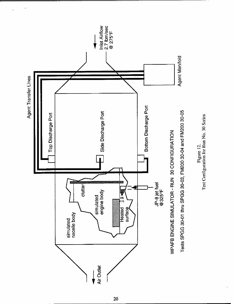
In the final configuration tested, Run No. 30, JP-8 was used again as fuel with a high internal airflow rate. This series is summarized in Table 5. Success in extinguishing the fire without relight was obtained with six gas generators fired over a sequence of five seconds. Concerns arose over the effect of the more remote location of the gas generators as compared Phase I tests, so the test setup was modified for the final two tests. The agent manifold was moved adjacent to the nacelle and used only side port discharge. This test apparatus change had a dramatic effect on the results, requiring only three gas generators fired over 1.5 seconds to completely extinguish the fire without relight. This is a total agent weight of 3.0 lbm which is 1.33 times the amount of FE-25 required in tests previously conducted by Wright Patterson for this test configuration. However, a direct comparison between the FE-25 results and the final two tests in this series may be invalid due to the change in discharge manifold location. To make a direct comparison the FE-25 test should be re-run with the same discharge location, and further tests conducted with OAC's gas generator system to determine the minimum agent required.
The final two tests in Run No. 30 demonstrated that proper distribution is an important parameter of the gas generator fire suppression systems. Budget and time considerations did not permit

further testing in the configuration with the agent release near the fire. Future testing should investigate the effects of agent discharge location and the optimization of system performance with the most realistic of these scenarios. Other future work might include testing of other hybrid agents, such as water solutions of various salts (lower freezing point, fire suppressant chemical activity), and further testing of perfluorcarbons.

INTRODUCTION
The Advanced Fire Suppression Technology (AFST) Research and Development Program is being conducted by OAC for Wright Patterson Air Force Base (WPAFB) under Contract No. F33615- 93-C-3404. The program goal is to evaluate the effectiveness of gas generator technology to replace Halon in suppressing aircraft drybay and engine nacelle fires. This activity includes the design, development and testing of solid propellant and hybrid gas generator technology. Phase I included an initial evaluation of filtered and nonfiltered solid propellant gas generators as well as select hybrid agents and was summarized in Document No. 95-R-1922. The goal of Phase II was to optimize the most promising Phase I systems. A summary of the Phase II activities are presented in this report.
In July of 1995, OAC completed Phase II engine nacelle fire suppression testing. The scope of this activity included testing and performance optimization of solid propellant-only and hybrid gas generators. The gas generator and hybrid units were of an established design with which OAC has prior test experience . Fire suppression tests were run at WPAFB in the Aircraft Engine Nacelle Test Facility (AENTF). The objective of this report is to document the Phase U activities performed and provide a recommended scope of work for follow-on development programs.
The following sections will present an overview of the design and development of the test articles used in the engine nacelle testing followed by individual sections detailing test results, conclusions and recommendations.

TEST ARTICLE DESCRIPTION
Propellant The propellant that OAC used in Phase II development testing was RRC-FS01-40 which is a proprietary mix developed specifically for fire suppression applications. This propellant is a modified version of a nonazide automobile airbag propellant. The ingredients were modified to change the exhaust paniculate constituents such that no material compatibility issues exist. Effluent compatibility studies indicate no reaction or pitting occurs with the following materials:
6061-T6 (Alodined) 7075-T6 (Mil-P-85582 coated) 7050 (Mil-P-85582 coated) Ti-6A1-4V (Untreated)
Graphite Epoxy Kevlar
In addition, the propellant has survived an accelerated aging test comprised of 244°F for 1000 hours and showed no performance degradation.
While the ingredients to RRC-FS01-40 propellant are proprietary, OAC must divulge the exhaust gas composition since the exhaust gas is the actual agent used in suppressing the fire. Table 1 provides detailed properties of the propellant. The propellant generates 54.25% gaseous products and 45.75% solid particulate. The gaseous products consist of 42.5% N2, 44.7% CO2 and 12.8% H2O by weight. At least 95% of the solid particulates remain in the gas generator regardless of the gas generator configuration.
Table 1. RRC FS01-40 Propellant Properties
Part No.
Size
Burn Rate
Exponent (n)
Density
DOT Classification
RRC-FS01-40
Various
Proprietary
Proprietary
Proprietary
1.3 (Class B)
Effluent Properties (based on 100 g propellant)
Moles/ 100 g
Grams/ 100 g
Weight Volume (Mole) (%)
N2 0.82356 23.06 42.5 46.8
CO2 0.55126 24.25 44.7 31.3 H20 0.38572 6.94 12.8 21.9
Total Gas 1.761 54.25 100 100
Total Solids NA 45.75 100 NA

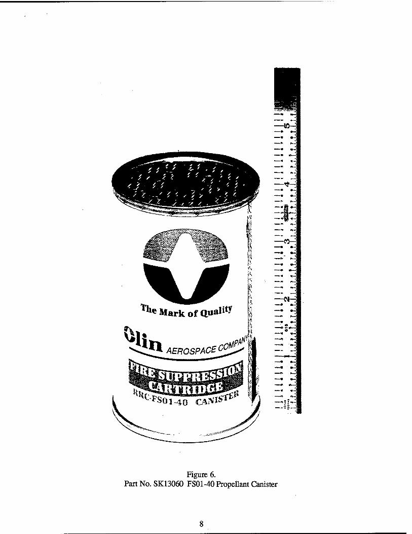
Gas Generator/Manifold All the gas generators used in Phase II development are of a heavyweight refurbishable design. That is, the devices can be dismantled and cleaned after use, reloaded and reused hundreds of times. This technique has been shown to be the most cost effective means to fabricate test hardware when weight is not an issue. The hardware used in Phase II was an improved modular design with a greater ease of loading and assembly. There were two primary differences between this hardware and that was used previously. First the modular design allows the gas generator unit to be tested by itself or to have the hybrid body attached to it and filled with the hybrid agent to make the hybrid generator assembly. Second unlike the earlier hardware, in which stacks of individual propellant pellets had to be loaded into the gas generator for each test, in this test series the hardware used pre-packaged propellant canisters. Each generator used one of these canisters which contains one pound of solid propellant. This containerized propellant design speeds up the disassembly, cleanup, and reloading process compared to the previously tested design.
The test configuration OAC chose to test at the WPAFB Engine Nacelle Test Facility were the Fire Suppression Gas Generator Assemblies part numbers SK13057 and SK13058. The unit is of a modular design that allows it to be used with the gas generator section only (Figure 4) or the hybrid body may be attached to the gas generator assembly yielding a hybrid generator assembly (Figure 5). The assemblies are designed to use OAC's pre-loaded FS01-40 propellant canister (Figure 6).
Up to ten gas generators may be mounted to the manifold as shown in Figure 7. By adjusting the quantity of gas generators and the timing sequence of gas generator functioning, this system provides the capability of producing a wide range of agent mass flow rates in a simple hardware configuration. The manifold is connected to the engine nacelle simulator by three lengths of 5/8 inch o.d. CRES tubing. The manifold was located approximately 40 feet from the nacelle agent discharge ports for all but the final two tests of this phase of testing. The arrangement of the fire suppressant agent distribution system including the manifold and connecting tubing is shown in Figure 8.
Engine Nacelle Simulator The Wright-Patterson Aircraft Engine Nacelle (AEN) Fire Test Simulator is illustrated in Figure 9. This fixture can operate in numerous configurations by using different size engine and clutter inserts, fire locations, hot surface temperatures, internal air flow rates and air temperatures. For Phase II testing the nacelle simulator was set up in three different configurations (one for each test series) as shown in Table 2, below.
Table 2. Engine Nacelle Test Configuration for Phase II Testing, July1995
Series No.
Fuel Fuel Temp.
(°F)
Internal Air Flow (lbm/sec.)
Air Temp.
(°F)
Fire Location
Heated Surface Temp.
(°F)
Pre-burn time (sec.)
13 83282 Hydraulic
fluid
100 2.7 275 bottom 1300 5
14 JP-8 100 0.9 275 bottom 1300 20
30 JP-8 325 2.7 275 bottom 1300 5

ooo 3 £ VI
< s 6 c <u Ü Vi
O u 3 «1
S PS
CO »9
fl DH OH s
CO
I 00 «n o CO 1—(
CO
0 55

ooo
oo oo
>n
s
2 <o c a Ü
a O
>> Ä
«3
OH OH 3
CO
r- o en 1—I
-« «—
Figure 6. PartNo.SK13060 FS01-40Propellant Canister

CO CO CC 111 o CO V- < < o CC
O co^
$ oo cc IJCO LU <% z Q<3 ill _J o o o-*- CO <
LLLL
o <z o 20 z ZH X CO
m £2 3 OR LL Ü.O LU oü CC T^<
< X H coQ COLU
OUJ occ 3<
öß C
u H
I <o c <l> Ü «1 CO
o c .9
CA
B & s
^ 22
T3
•a
e o •0 s
x>
c o •0 Ü
o U
LU
< a

CO CD c
c CO
c CD
<
CO
O
CD c CD O) CO CO
o
CD C (D D) CO CO
T3
CO
c CD
<
CD CD
S 0) OS >->
on c o
• 1—1
3
C D
< C
CO 9J
00 «U rv
a 3
cu E O
6 CO U
I—<
u z CD C
'3b e m
10

0\
1 c/3
13
s! Hog
e W
11

DISCUSSION OF TEST RESULTS
In July 1995, OAC performed Engine Nacelle Suppression tests using OAC gas generator technology. WPAFB provided the engine nacelle simulator located at the Advanced Engine Nacelle test facility. The Engine Nacelle Simulator may be set up with many different configurations and operating conditions. Internal clutter may be simulated and two engine sizes are available. Internal airflow and air temperature are easily set to the desired values. Hot surface re- ignition temperatures of up to 1300T are possible and either JP-8 or 83282 hydraulic fluid may be used as the fuel for the fire. In summary, this fixture is an outstanding tool for evaluating Halon- 1301 and its replacement/alternative agents. Prior to OAC arrival, WPAFB had completed a test series using FE-25 agent. The same run configurations used with the FE-25 were used for OAC gas generator testing.
Run No. 13 Results The Engine Nacelle Simulator configuration for Run No. 13 is illustrated in Figure 10. The test configuration used the small engine simulator with a 2.7 lbm/sec airflow. Clutter was in the high simulation mode. Hydraulic fluid (83282) at 100°F with 5 seconds of preburn provided the fuel for the fire located at the bottom of the simulator. The flow of hydraulic fluid was stopped at the time of agent release (time zero). The agent discharge location was the top, side and bottom discharge ports.
Table 3 summarizes the results for this test series. There were a total of ten tests run in this series, seven with propellant-only gas generators and three with hybrid units. Water was the agent used in the hybrid units.
In this series, the plan was to use multiple gas generators fired in sequence and determine how many gas generators and what time distribution were required to extinguish the fire. The series was started with four gas generators and the second test indicated that closer time spacing was more effective, so the next few tests were to use only two gas generators with a short time sequence. Unfortunately, on the third test, one gas generator failed to fire. The fourth test was a repeat of number three, and was unsuccessful. By shortening the time with two gas generators to 0.2 seconds with test five, extinguishment with a very rapid relight was achieved It was apparent that two gas generators were not enough, so the next tests were to use three gas generators and determine the required time spacing. On test number six, one gas generator did not fire, again negating the results, so the test was repeated as test number seven with moderate success, since the fire relit. Results thus far seemed to indicate that three gas generators were just short of enough agent to extinguish the fire, so the next test was a hybrid unit using water with near the same total agent level (two gas generators and 0.88 lbm of water) which was unsuccessful. Increasing the number of gas generators and the amount of water to 3.0 lbm and 1.32 lbm, respectively, in test number nine yielded complete success. The final test in the series attempted to repeat the results of test nine, but was unsuccessful since flame relight did occur. Looking back at the data now, it is likely that four gas generators would also extinguish the flame if the timing would be decreased from the 1.5 seconds as used in the second test.
Again briefly summarizing the results of test series number 13. Two gas generators were the minimum number required to put out the fire, but it relit very soon thereafter. Three gas generators timed to fire in 0.5 seconds or less yielded better success with longer times to relight after extinguishment. However, it took three gas generators firing in a sequence up to 0.3 seconds and 1.32 pounds of water in a hybrid configuration to completely extinguish the fire. This is a total
12

agent weight of 4.32 lbm which is 1.57 times the amount of FE-25 required in tests previously conducted by Wright Patterson for this test configuration.
13

'E <0
c CD
<
CO
O 0} on
CO m T—
z O CM
0 O 2 H X e < =5
SZ _) *—* tu 0 CD li
CO 0
3 M §
z: CO UH ea u
ü 0 CM
3
CO X C y-, O
77 r*. U Z5 0
1 *-> CO
rr 0 lu
T- H
rr CD 0 CD H 0.
3 iß 3
3 S JE </> O LU CO Z CD CD Z CD LU Q_
CO en LL w < CO Q. CD
14

c o
• tH CO CO
« a UL eo
80S
*at »SI w£g
OH
CO
4-» ■ J3
a 0 eö CO vq cö ^t eeJ to
00 c
■*' C a T-H c cs' C "3
0 s rf
4-» 4-» •4-» 4-* 4-» CO 4-»
O 3 3 3 3 3 O 0 O 0 es
O 00
O q "3; O .8 s >
T-H
V g u <-** £ © !J t-H 1-4
4i HH <D 4> 0 <D 0
c c e c c
*"* JH OX) S3 rf Tf ■* VO rt VO en ■* ^ "* e
•TH
Ag<
vi
si
0 0 0 ö ö Ö © Ö ö Ö E
c S*-i <u 1« C > 0 O eS eS eS ■* ■^t cs es W 0 4-rf O 0 Hrt ö Ö Ö Ö Ö Ö Ö
9 a> ft I-H
m CS W®
in m VO en en en C\ in r- r» Ö- O rt -* en r- r~ i> 0 O >n in >3 "H C 4-» 4) CO T—1 l-H O 0 0 0 T-H T-H T-H T-H
Si) *H
<
4-» e
O O © © 0 q q 00 00 en
es en
3£ rf ^f <—1 CN CS* <s' en cN -* -* 0 H
•Ö •c ~ *J 00 es es £& ' 1 1 ' 1 1 1 (SO
Ö en T-H
en
£>© a m "1 bO
c •?H
O
T-H
©" m <S in
m q (N
en en
q^ pH Q^5
en T—1 0 q Ö q cs O T-H T-H
eS «n m 0" O" 0 O 0 0
O X. 1—( O 0 0 0
0" 0"
© CO ^t ■t i—1 es eS es en cN en en
>»b CO
T—c es en ■<* m VO p- O T-H . 0 0 O q q O
I O
1 OO O 8 0 en en
T—t en T-H
en en r—1
en T-H
en 1 cn T—1
1 en T-H
I en
4-* a O Ü O O O O O a
0 a
O a £ 0
CL. a OH
O CM
Ü a, Ü CL, OH
O CM
CO CO 00 CO CO co co
fc> a
a
•c
©K
es 00 OQ
15

Run No. 14 Results The Engine Nacelle Simulator configuration for Run No. 14 is illustrated in Figure 11. The test configuration used the small engine simulator with a 0.9 lbm/sec airflow. Clutter was in the high simulation mode. JP-8 at 100T with 20 seconds of preburn provided the fuel for the fire located at the bottom of the simulator. The flow of JP-8 fuel was stopped 5 seconds after agent discharge. The agent discharge location was the top, side and bottom discharge ports.
Table 4 summarizes the results for this test series. There were a total of four tests run in this series, three with propellant-only gas generators and one with a hybrid unit. Water was the agent used in the hybrid test
In the first two tests, neither four nor six gas generators were able to extinguish the flame without relight. However, in the second test, relight was eight seconds after the flame went out, so it was possibly close to working. Therefore, it was decided to try widening the gas generator sequencing time frame with and without the incorporation of a hybrid agent at near the same total agent level. Both these tests were successful. The fourth test used six gas generators with the firing sequence extended out to 9.0 seconds. The hybrid test used five gas generators and 2.2 lbm of water, also with a 9.0 second time sequence. The total agent mass in these two tests was 6.0 and 7.2 lbm, respectively, at 1.14 and 1.37 times the amount of FE-25 agent required in the Wright Patterson test series.
16

CO CD c
0)
c CO
c a> <
O
C CO
c CD O) <
C/3
1) t/1 ^
z o
o 1
6
1- CD ^ < n . 1 □c Q_ c* ID CD
CO ■a
P 3 «2
LL c or c Z o
co CO o
tin c3
o ^ 3 ■si- 1—
O c z Z>
CM Ü U ■4-*
CD 3 cc CM
GO
~ LL 1 O 1
H CD o DC "3" —'O O
1- ^—
CO o a y;5 3
z>
03 Lil Z CD Z LU CD LL < a.
CD a. CO
O 1
«^ 1—
CD CD 0_ CO CO to 0
17
c o
• I-l CO Vi
8 & co o a ,0 0 3
8 0S
»et <D 3 5
wgg 43 >• SS
a* "3" a>
•§ H
eg
Ü
4-4 ■»-> 1 Xi A
&£ Ml w> 0 (S
c-- C\ 8 y O Ö
0 3
en Tl 3 s 0 cs 0 00 •<* Ü
& 1—1 T—1 SO fN 1) en &
4-> Ü
bO s-s <* "«* SO ■<*
3 MM 0 O O O F,
4-^
3 S*-| d> «*-c > 0
W
(2 «n m m W)
u-> f"* ~ BÖ so ■3- r~ ■*
S- 0 r~- i-H en 1—1
0 l—i »—I ^H
bß •-■ <
4-* s u bß,-^ < 6 0 0 cN O
1§Ö ^r SO r» SO
O H
•0 ■C --» -5 S cs
(N
4^© O
bfl .5
0 0" p SO*
0
§^ V) >r> vb 00 "">o<
r* en <J °,o «,o\ Id
O W CN «"*' «n «^vo
O cJ 0 O O 0 0 O O
© en «* so m SO
&o oo T—1 cN "tf
0 0 ■4
O i O
I
0 1
»—1
Ü O O S
O £ O
OH O CL,
O CO CO CO
b CO
3 0> bO CO
•c
©E
4-»
Ö 2
.fiS OH
d<4-> —
•i°
OS x:2
4^
u
o >
2 9 3 c
«öl? «s o s ui Is
©<§£
o «n 55
3 bfl
_S "4-»
X 0
&
■a o u u en
§
TOO ^^ e»
PH
S 2 o
PQ *ö c a
4 gco
:i^ 3 .O bpH 8®
.^3
SSB: If
s^ 2 o en
4J c Ü bfl
18

Run No. 30 Results The Engine Nacelle Simulator configuration for run no. 30 is illustrated in Figure 12. The test configuration used the small engine simulator with a 2.7 lbm/sec airflow. Clutter was in the high simulation mode. JP-8 at 100T with 5 seconds of preburn provided the fuel for the fire located at the bottom of the simulator. Fuel flow was continued for 5 seconds after agent discharge. The agent discharge location was the top, side and bottom discharge ports.
Table 5 summarizes the results for this test series. There were a total of seven tests run in this series, five with propellant-only gas generators and two with hybrid units. FM-200 (C3HF7) was the agent used in the hybrid units.
The first test with six gas generators and a timing sequence of 5.5 seconds did extinguish the fire but with relight. However, by shortening the time sequence by 0.5 seconds to 5.0 seconds and thereby increasing agent concentrations, success was attained.
Two hybrid tests using FM-200 at a total agent weight of 3.25 lbm which is 1.44 times the FE-25 required in the WP tests were unsuccessful.
To investigate the effect of the 40 foot transfer lines from the manifold to the nacelle, and the resultant decrease in agent temperature, the test setup was modified for the final two tests. The agent manifold was moved to within approximately 2 feet of the nacelle and only side port discharge was used. The configuration of these final two tests of the series is illustrated in Figure 13. This test apparatus change had a dramatic effect on the results, requiring only three gas generators fired over 1.5 seconds to completely extinguish the fire without relight This is a total agent weight of 3.0 lbm which is 1.33 times the amount of FE-25 required in tests previously conducted by Wright Patterson for this test configuration. Additional tests would be required to determine the minimum agent weight that would be needed to achieve success with the manifold located adjacent to the nacelle.
19
c CD
<
m O en O OJ CO 0 O CO O <"-> CM rr\ z ^
0 LL Ü 7;
h- ■O 1 < CZ
EC CO CM 06 3 •* ^ Ü 0
1 P ,0
LL Z O
0 CO
0 0
3
O CM s O CO LL
tau
c 0 z
ID CO~ O U
CD 3 LT O
CO
CO
|2 *- LL (D o rr CD
-Si. to 03 CM ft' w S5@
O O Q. CO
_i 3
2 £ CO O LU O z CO
0 0 z 0 LU D-
CD CO LL CO < CO 0_ CD
20

e o
l-c o< 3
00 V)
At 4—»
.so 3 n< en o « ■—i en OH
55
ö 55 B
•4-»
0) s n c •a ri
0Ä 3
OH
c Ü
4> fe- S2 K> &• es so in o
4-* -I-» 4-» 1 .fi -C XJ
bO W) bo m •^H r—i CO CO U3
>*" fi o c
CN C fi fi o B
fi O fi
4-* 4-H CO 4-* 3 3
T3 3 o 5 fi O m q r—1 LH s_ CN CN
O u .8 CN H i—( a 5 1-H 7—1
UH fi <D fi
«-> <u bO S:S «fr "* ■* v© ■* vo Tt .fi bo ö ö Ö d d d d © g <'S
e S*-i 0} (4-1
? o W 13 >n in >n m >n >n >n
m CN 1© r- r- en ■<* ■«* r- en ** ° VO VO en •<t ■<* vo en fi ts 4J CO oi CN »—i r—1 i—t CN >—i
(30 t-c
<
4-» c
q q q m CN
m CN O ©
3S vd vd en en en vd en
o H
t3 "C O-
i i ■ >n CN
«n eN
■ ■
>>© a
^ ^ bO ITi o in
«"im <© vq ^im >n
C u «^in o.vn q «lin
t-H
c2 ü '""l.in °„«n en O O ^.«n
in
o w »'W <*."*" © "1-* ©
ö q o d O ©
o o O
© CO v© VO en -H 7—1 VO en
&b CO
1—1 CN en s q VO r- q o O o o Ö
55 ö 1 o 1 o Ö d 1
© 1
© en en en en en m ^ 00 ^> O O O 1 8 0@ Ü®
£ O O O 9 O O OH OH OH 2 2 0H OH 00 00 00 E E 00 00
o © CN
B ID WO CO /■
"2 (li
©ffi >>o
O s
fi o ■S
c Is ©< &4-S
CO
O
©
Is fit- olen
j«en <4H ä jjj
RgSSji
21

o < er o
o Ü o CO
z oc TO Q
o I o
\o o I o
ci as
(D H
■r* S
c/3 o
d Z c
' 3 2* 3 'S
m
fc
3
"ts N. c T3 O o O i u 2
1
O CO
rr O H O
Q. 0>
< CO • *■•«
_j ■o o Z> 2
c CO s
CO CD O
LU O z CO
o o z (D LLI 0. CD CO
< 0.
CO *-* CO CD I-
22
CONCLUSIONS AND RECOMMENDATIONS
Conclusions Fortunately, the problem experienced in Phase I testing with thermocouple re-ignitions of the flame mat put some of the earlier results into question was resolved in this series by replacement of the braided wires. Unfortunately, time and budget constraints limited the testing done during this phase of the contract. With additional test time available more could have been learned about the characteristics and effectiveness of this suppression system. Another problem which hindered testing efficiency was the recurring incidence of failures of gas generators to ignite due to a variety of electrical and/or test anomalies. Most problems were traced to a faulty connection to the gas generator at the firing leads. Future testing should include a more positive firing lead connection and a pre-test check-out.
In test Run No. 13 with 83282 hydraulic fluid as the fuel it was only possible to completely extinguish using a hybrid gas generator with three gas generators and 1.32 lbm of water. The total agent mass was 1.57 times that for FE-25 in the same test configuration.
With a low internal air flow rate and JP-8 as the fuel (Run No. 14), complete extinguishment was achieved in both propellant-only and hybrid gas generator configurations. Success was attained with six propellant-only gas generators at 1.14 times the required FE-25 mass. A hybrid configuration using 2.2 lbm of water and five gas generators for a total agent mass of 1.37 times that required for FE-25 was also successful.
With a high internal air flow rate and JP-8 as the fuel (Run No. 30), complete extinguishment was achieved with six gas generators. This represents a total agent mass of 2.67 times that required for FE-25. Two hybrid unit tests using FM-200 were unsuccessful. However, one of the two gas generators did not fibre in the second FM-200 test and more material was unavailable for a repeat. Therefore, the results of two gas generators and 2.5 lbm of FM-200 are not known.
Overall OAC's gas generator fire suppression system required total agent weights higher than the amount of FE-25 agent necessary to extinguish the three fire types evaluated Previous test series conducted by OAC have demonstrated the importance of proper agent distribution for effective fire suppression. During the testing discussed in this report, the very dramatic effect of gas generator proximity to the fire zone was shown. This effect may be attributed to the cooling of the agent gases in the transfer lines.
During the transfer of the agent gases in the 40 foot run from the manifold to the dispersion point, the gases are cooled significantly, and, therefore, their volume reduced proportionally. This results in a reduction in the partial pressures of the agent within the simulated engine nacelle as compared to agent introduction directly at the dispersion point. Further contributing to this effect is the use of three separate transfer lines. By moving the manifold from 40 feet away from the nacelle to within two feet, as in the final two tests of series no. 30, the required agent weight was cut in half. Additional reductions in amount of agent required may be expected by discharging agent from all nacelle ports, not just the side port, as in these tests.
Recommendations Some work has been done more recently at OAC using aqueous solutions of salts, some having chemical fire suppressant activity. These hybrid agents are attractive not only because of chemical
23

activity but also due to the freezing point depression of the water. It would be potentially productive to further test hybrid units in the engine nacelle simulator using some of these aqueous solutions.
Additional testing to further optimize gas generator series timing may also be warranted. The effect of agent dispersal location on fire suppression effectiveness should be further studied. It might be a good idea to study multiple fire scenarios to define the best overall agent dispersion pattern, then to fully characterize FE-25 and OAC gas generator performance in this configuration.
24