tail-f network control system 3.3 getting started guide · tail-f network control system 3.3...
TRANSCRIPT

Tail-f Network Control System 3.3 Getting Started Guide
First Published: November13,2014
Last Modified: November,2014
Americas HeadquartersCisco Systems, Inc.
170 West Tasman Drive
San Jose, CA 95134-1706
USA
http://www.cisco.com
Tel: 408 526-4000
800 553-NETS (6387)
Fax: 408 527-0883

THE SPECIFICATIONS AND INFORMATION REGARDING THE PRODUCTS IN THIS MANUAL ARE SUBJECT TO CHANGE WITHOUT NOTICE. ALL STATEMENTS,INFORMATION, AND RECOMMENDATIONS IN THIS MANUAL ARE BELIEVED TO BE ACCURATE BUT ARE PRESENTED WITHOUT WARRANTY OF ANY KIND,EXPRESS OR IMPLIED. USERS MUST TAKE FULL RESPONSIBILITY FOR THEIR APPLICATION OF ANY PRODUCTS.
THE SOFTWARE LICENSE AND LIMITED WARRANTY FOR THE ACCOMPANYING PRODUCT ARE SET FORTH IN THE INFORMATION PACKET THAT SHIPPED WITHTHE PRODUCT AND ARE INCORPORATED HEREIN BY THIS REFERENCE. IF YOU ARE UNABLE TO LOCATE THE SOFTWARE LICENSE OR LIMITED WARRANTY,CONTACT YOUR CISCO REPRESENTATIVE FOR A COPY.
The Cisco implementation of TCP header compression is an adaptation of a program developed by the University of California, Berkeley (UCB) as part of UCB's public domain versionof the UNIX operating system. All rights reserved. Copyright © 1981, Regents of the University of California.
NOTWITHSTANDINGANYOTHERWARRANTYHEREIN, ALL DOCUMENT FILES AND SOFTWAREOF THESE SUPPLIERS ARE PROVIDED “AS IS"WITH ALL FAULTS.CISCO AND THE ABOVE-NAMED SUPPLIERS DISCLAIM ALL WARRANTIES, EXPRESSED OR IMPLIED, INCLUDING, WITHOUT LIMITATION, THOSE OFMERCHANTABILITY, FITNESS FORA PARTICULAR PURPOSEANDNONINFRINGEMENTORARISING FROMACOURSEOFDEALING, USAGE, OR TRADE PRACTICE.
IN NO EVENT SHALL CISCO OR ITS SUPPLIERS BE LIABLE FOR ANY INDIRECT, SPECIAL, CONSEQUENTIAL, OR INCIDENTAL DAMAGES, INCLUDING, WITHOUTLIMITATION, LOST PROFITS OR LOSS OR DAMAGE TO DATA ARISING OUT OF THE USE OR INABILITY TO USE THIS MANUAL, EVEN IF CISCO OR ITS SUPPLIERSHAVE BEEN ADVISED OF THE POSSIBILITY OF SUCH DAMAGES.
Any Internet Protocol (IP) addresses and phone numbers used in this document are not intended to be actual addresses and phone numbers. Any examples, command display output, networktopology diagrams, and other figures included in the document are shown for illustrative purposes only. Any use of actual IP addresses or phone numbers in illustrative content is unintentionaland coincidental.
Cisco and the Cisco logo are trademarks or registered trademarks of Cisco and/or its affiliates in the U.S. and other countries. To view a list of Cisco trademarks, go to this URL: http://www.cisco.com/go/trademarks. Third-party trademarks mentioned are the property of their respective owners. The use of the word partner does not imply a partnershiprelationship between Cisco and any other company. (1110R)
© 2014 Cisco Systems, Inc. All rights reserved.

C O N T E N T S
C H A P T E R 1 Purpose of the Document 1
Product Overview 1
Main Features 2
Architecture Overview 3
Typographical Convention 4
C H A P T E R 2 Running NCS Examples 5
Instructions to Run NCS Examples 5
Common Mistakes 6
C H A P T E R 3 NCS Basics 9
Starting the Simulator 10
Starting NCS and Reading Device Configuration 11
Reading Device Configuration into NCS 11
Writing Device Configuration 14
More on Device Management 16
Creating Device Groups 17
Device Templates 17
Defining Multi-vendor Templates 18
Policies 21
Out-of-Band Changes 23
Resolving Conflicts 24
Conflict Resolution 28
C H A P T E R 4 Network Element Drivers and Adding Devices 31
Device Authentication 32
Connecting Devices for Different NED Types 33
CLI NEDs 33
Tail-f Network Control System 3.3 Getting Started Guide iii

NETCONF NED for JunOS 33
SNMP NEDs 33
Generic NEDs 35
Multi-NED Devices 35
Administrative State for Devices 35
Trouble-shooting NEDs 36
C H A P T E R 5 Managing Network Services 39
A Service Example 40
Running the Example 42
Service-Life Cycle Management 44
Service Changes 44
Service Impacting Out-of-Band Changes 45
Service Deletion 47
Viewing Service Configurations 47
Defining Your Own Services 49
Defining the Service Model 50
Defining the Mapping 53
Reactive FASTMAP 59
Reconciling Existing Services 59
Brown-field Networks 60
C H A P T E R 6 Compliance Reporting 61
Creating Compliance Report Definitions 62
Running Reports 62
Understanding Reports 63
C H A P T E R 7 Scripting 67
NCS CLI Scripts 68
NCS REST Scripts 68
Python MAAPI Scripts 69
NCS NETCONF Scripts 70
Plug and Play Scripts 71
Example Command Script 72
Tail-f Network Control System 3.3 Getting Started Guideiv
Contents

C H A P T E R 8 The NCS Web User Interface 73
Using the Web UI 74
Saving Transactions 75
C H A P T E R 9 Developing Service Applications 77
NCS Java VM and APIs 77
Developing a Service 78
Setting Up the Environment 78
Creating a Service Package 80
Creating a Service Model 82
Managing the NCS Java VM 83
A First Look at Java Development 84
Using Eclipse 85
Writing the Service Code 93
Fetching the Service Attributes 93
Mapping Service Attributes to Device Configuration 94
Combining Java and Templates 98
VLAN Feature Template 99
VLAN Java Logic 101
Building a Java and Template Solution 102
C H A P T E R 1 0 Administration 103
Installing NCS 103
Uninstalling NCS 104
Running NCS 105
Starting and Stopping NCS 105
NCS User Management 106
Adding a New User 106
Packages 107
Adding and Upgrading a Package 108
Simulating the New Device 109
Adding New Devices to NCS 109
Configuring NCS 109
Run-time Configuration 112
Tail-f Network Control System 3.3 Getting Started Guide v
Contents

Monitoring NCS 113
Backup and Restore 113
Backup 113
Restore 113
Tail-f Network Control System 3.3 Getting Started Guidevi
Contents
C H A P T E R 1Purpose of the Document
The purpose of this User Guide is two-fold:
• To get an understanding of NCS as a service orchestration and network configuration tool.
• To be used as a tool to get started using NCS.
This document only covers the most essential parts of using NCS to manage a network. It also gives a shortintroduction to programming aspects at the end. Furthermore, the features are only covered at an introductorylevel. For the detailed instructions, see the NCS User Guide.
This chapter contains the following sections:
• Product Overview, page 1
• Architecture Overview, page 3
• Typographical Convention, page 4
Product OverviewCreating and configuring network services is a complex task that often requires multiple integrated configurationchanges to every device in the service chain. Additionally changes need to be made concurrently across alldevices with service implementation being either completely successful or completely removed from thenetwork. All configurations need to be maintained completely synchronized and up to date. Tail-f NCS solvesthese problems by acting as interface between the configurators (network operators and automated systems)and the underlying devices in the network.
NCS does this by providing the following key functions:
1 Representation of the services.2 Multi-vendor device configuration modification in the native language of the network devices.3 Configuration Database (CDB) with current synchronized configurations for all devices and services in
the network domain.
Tail-f Network Control System 3.3 Getting Started Guide 1

4 Northbound interfaces that can be accessed via Network CLI, WebUI or with automated systems usingREST, Python, NETCONF, Java or other tools.
Figure 1: Tail-f NCS
Network engineers use Tail-f NCS as a central point of management for the entire network, using a "networkCLI" or a web-based user interface. While this guide will illustrate the use cases with the CLI it is importantto realize that any northbound interface can be used to achieve the same functionality.
All devices and services in the network can be accessed and configured using this CLI, making it a powerfultool for network engineers. It is also easy to define roles limiting the authority of engineers to the devicesunder their control. Policies and integrity constraints can also be defined making sure the configuration adhereto site standards.
The typical workflow when using the network CLI in NCS is as follows:
1 All changes are initially made to a (logical) copy of the NCS database of configurations.2 Changes can be viewed and verified by the network operator prior to committing them.3 The changes are committed, meaning that the changes are copied to the NCS database and pushed out to
the network. Changes that violate integrity constraints or network policies will not be committed. Thechanges to the devices are done in a holistic distributed atomic transaction, across all devices in parallel.
4 Changes either succeed and remain committed or fail and are rolled back as a whole returning the entirenetwork to the uncommitted state.
Main FeaturesThe main features of NCS are:
• Intuitive to the methods currently used for configuring network services using either Web UI or networkCLI.
Tail-f Network Control System 3.3 Getting Started Guide2
Purpose of the DocumentMain Features

• Device changes are whole and either completely succeed or are completed discarded, no partialconfigurations are left.
• Fine-grained deep control of all elements in the service.
• Centralized configuration database that is synchronized with the network. Reconciliation can be donein any direction: to network, from network.
• Rich set of user interfaces (WebUI, CLI) and scripting interfaces (REST, Python, NETCONF, JavaScript).
Architecture OverviewThis section provides a broad overview of the NCS architecture and functionality.
Figure 2: NCS Architecture
NCS has two main layers: the Device Manager and the Service Manager. They serve different purposes butare tightly integrated into one transactional engine and database.
The purpose of the Device Manager is to manage device configurations in a transactional manner. It supportsfeatures likes;; bidirectional device configuration synchronization, device groups and templates, and fine-grainedreal-time changes to devices.
The Service Manager makes it possible for an operator to manage high-level aspects of the network that arenot supported by the devices directly, or is supported in a cumbersome way. With the appropriate servicedefinition running in the Service Manager, an operator could for example configure the VLANs that shouldexist in the network in a single place, and the Service Manager compute the specific configuration changesrequired for each device in the network and push them out. This covers the whole life-cycle for a service:creation, modification and deletion. NCS has an intelligent easy to use mapping layer so that network engineerscan define how a service should be deployed in the network.
Tail-f Network Control System 3.3 Getting Started Guide 3
Purpose of the DocumentArchitecture Overview

NCS uses a dedicated built-in storage Configuration Database (CDB) for all configuration data. NCS keepsthe CDB in sync with the real network device configurations. Audit, to ensure configuration consistency, andreconciliation, to synchronize configuration with the devices, functions are supported. It also maintains theruntime relationships between service instances and the corresponding device configurations.
NCS comes with Network Element Drivers, NEDs, that communicates with the devices. NEDs are not closedhard-coded adapters. Rather, the device interface is modeled in a data-model using YANG (RFC 6020). NCScan render the underlying commands from this model, including for example a Cisco IOS CLI. This meansthat the NEDs can easily be updated to support new commands just by adding these to the data-models. NCSin combination with the NEDs will apply device configuration changes as atomic change sets.
NCS netsim is used to simulate devices. Netsim can simulate management interfaces like Cisco CLI andNETCONF. It does not simulate the network behavior.
NCS supports a rich variety of APIs and User Interfaces. Independent of the device types NCS will render anorthbound Juniper-Style and Cisco XR style network wide CLI. This will support all devices and services.The same is true for the NCS WebUI.
Scripts can be written using Python, REST, and NCS CLI or other tools to automate network activities.
Typographical ConventionThe following table describes the typographical convention used in the CLI snippets throughout this guide.
ExamplePrompt
$ pwdUnix prompt
admin@ncs# show running-configNCS CLI Operational mode
admin@ncs(config)# show configurationNCS CLI Configuration mode
admin@ncs(config)# devices device c0 config ios:interface \FastEthernet 1/0 switchport mode trunk
A (\) at the end of a commandindicates that the input continueson the next line
Commands and user-entered text appear in bold font;; for example, $ncs --stop. Terminal sessions andinformation the system displays appear in courier font;; for example, Entering configuration mode
terminal.
Tail-f Network Control System 3.3 Getting Started Guide4
Purpose of the DocumentTypographical Convention

C H A P T E R 2Running NCS Examples
Throughout this guide wewill refer to examples included with the product. If you have a NCS system installedit is recommended to run the examples.
The high-level procedure is as follows:
1 Make sure you source the ncsrc file in the NCS installation directory.2 cd to the example home directory.3 Prepare the simulated network using the netsim tools.4 Prepare the NCS example configuration.5 Start netsim.6 Start ncs.7 Run the scenario.8 Stop netsim.9 Stop ncs.
For detailed instructions see Instructions to Run NCS Examples, on page 5.
This chapter contains the following sections:
• Instructions to Run NCS Examples, page 5
• Common Mistakes, page 6
Instructions to Run NCS ExamplesThis guide refers to some of the examples in $NCS_DIR/examples.ncs. Read and run the README files inparallel with this user guide.
Make sure NCS is installed according to the instructions in section Installing NCS. Source the ncsrc file inthe NCS installation directory. For example:
$ source /opt/ncs/ncsrcGo to the example:
$ cd$NCS_DIR/examples.ncs/getting-started/using-ncs/1-simulated-cisco-ios
Then follow the instructions in this section and the README that is located in the root of all examples.
Tail-f Network Control System 3.3 Getting Started Guide 5

Every example directory is a complete NCS run-time directory. The README file and the detailed instructionslater in this guide show how to generate a simulated network and NCS configuration for running the specificexamples. To run the examples follow the below steps:
Step 1 Create a simulated network using the command ncs-netsim --create-network.For example:
$ ncs-netsim create-network $NCS_DIR/packages/neds/cisco-ios 3 c
This creates three Cisco IOS devices called c0, c1, and c2.
Step 2 Create NCS run-time environment.For example:
$ ncs-setup --netsim-dir ./netsim --dest .
The dot '.' refers to current directory, that is, 1-simulated-cisco-ios.Note
This does the following:
1 --netsim-dir: Reads netsim data (list of devices) from the ./netsim directory. This was created by ncs-netsimcreate-network command.
2 --dest: Creates local directories for NCS logs, database files, and NCS configuration file to the current directory.
Step 3 Start netsim
$ ncs-netsim start
Step 4 Start ncs
$ ncs
It is important to make sure that you stop ncs and ncs-netsimwhen moving between examples. The followingsequence illustrates how to shift from the 1-simulated-cisco-ios example to the datacenter/qinq example.
$ cd $NCS_DIR/examples.ncs/getting-started/1-simulated-cisco-ios$ ncs-netsim start$ ncs$ ncs-netsim stop$ ncs --stop
$ cd $NCS_DIR/examples.ncs/datacenter/qinq$ ncs-netsim start$ ncs$ ncs-netsim stop$ ncs --stop
Common MistakesThis section lists the four most common mistakes in brief. The exact steps are explained in later sections.
Tail-f Network Control System 3.3 Getting Started Guide6
Running NCS ExamplesCommon Mistakes

1 You have not sourced the ncsrc file:
$ ncs-bash: ncs: command not found
2 You are starting NCS from a directory, which is not a NCS runtime directory.
$ ncsBad configuration: /etc/ncs/ncs.conf:0: "./state/packages-in-use: \
Failed to create symlink: no such file or directory"Daemon died status=21
What happens above is that ncs did not find a ncs.conf in ./ so it uses the default in /etc/ncs/ncs.conf.That ncs.conf says there shall be directories at ./ such as ./state/packages-in-use which is not true.
Make sure you cd to the "root" of the example. Check that there is a ncs.conf file, and a cdb-dir.
3 You already have another NCS instance running (or same with netsim):
$ ncsCannot bind to internal socket 127.0.0.1:4569 : address already in useDaemon died status=20$ ncs-netsim startDEVICE c0 Cannot bind to internal socket 127.0.0.1:5010 : \address already in use
Daemon died status=20FAIL
In order to resolve the above, just stop the running NCS and netsim.
It does not matter where you started the running NCS and netsim, there is no need to cd back to the otherexample before stopping.
Note
4 The netsim devices have not loaded into ncs. This can happen if the order of commands are not followed.
To resolve remove the database files in the NCS database directory. In this way NCS will load the XMLinitialization files.
$ncs --stop$ cd ncs-cdb/$ lsA.cdb C.cdb O.cdb netsim_devices_init.xml$ rm *.cdb$ncs
Tail-f Network Control System 3.3 Getting Started Guide 7
Running NCS ExamplesCommon Mistakes

Tail-f Network Control System 3.3 Getting Started Guide8
Running NCS ExamplesCommon Mistakes

C H A P T E R 3NCS Basics
The purpose of this section is to get started with NCS, learn the basic operational scenarios and get acquaintedwith the most common CLI commands.
Make sure you have installed NCS and that you have sourced the ncsrc file in $NCS_DIR. This sets up pathsand environment variables in order to run NCS. So this must be done all times before running NCS, so it isrecommended to put that in your profile.
We will use the NCS network simulator to simulate three Cisco IOS routers. NCS will talk Cisco CLI tothose devices. You will use the NCS CLI and Web UI to perform the tasks. Sometimes you will use thenative Cisco device CLI to inspect configuration or do out of band changes.
Figure 3: The First Example
Both the NCS software and the simulated network devices run on your local machineNote
This chapter contains the following sections:
Tail-f Network Control System 3.3 Getting Started Guide 9

• Starting the Simulator, page 10
• Starting NCS and Reading Device Configuration, page 11
• Writing Device Configuration, page 14
• More on Device Management, page 16
• Conflict Resolution, page 28
Starting the SimulatorGo to examples.ncs/getting-started/using-ncs/1-simulated-cisco-ios.
Most of this section follows the procedure in the README file so it is useful to have that open as well. Firstof all we will generate a network simulator with three Cisco devices. They will be called c0, c1, and c2.
To start the simulator follow the below procedure:
Step 1 Run the command:$ ncs-netsim create-network $NCS_DIR/packages/neds/cisco-ios 3 cThis creates three simulated devices all running Cisco IOS and the will be named c0, c1, c2. Start the simulator:
$ ncs-netsim startDEVICE c0 OK STARTEDDEVICE c1 OK STARTEDDEVICE c2 OK STARTED
Step 2 Run the CLI towards one of the simulated devices.
$ ncs-netsim cli-i c1admin connected from 127.0.0.1 using console *
c1> enablec1# show running-configclass-map mmatch mpls experimental topmost 1match packet length max 255match packet length min 2match qos-group 1!...c1# exit
This shows that the device has some initial configurations.
Tail-f Network Control System 3.3 Getting Started Guide10
NCS BasicsStarting the Simulator

Starting NCS and Reading Device ConfigurationTo start NCS, the first action is to prepare directories needed for NCS to run and populate NCSwith informationof the simulated devices. This is all done with the ncs-setup command. (Again, ignore the details for timebeing).
Step 1 Go to the directory:
examples.ncs/getting-started/using-ncs/1-simulated-cisco-ios
Step 2 Run the following command:
$ ncs-setup --netsim-dir ./netsim --dest .
The (.) at the end of the command refers to current directory. What the command does is to create directoriesneeded for NCS in the current directory and populates NCS with devices that are running in netsim. We callthis the "run-time" directory.
Note
Step 3 Start NCS:
$ ncs
Step 4 Start the NCS CLI as user "admin" with a Cisco XR style CLI :
$ ncs_cli -C -u admin
NCS also supports a Juniper-Style CLI, that is started by using a -J modification to the command like this:
$ ncs_cli -J -u admin
Throughout this user guide the Cisco XR style commands areused.
Note
Reading Device Configuration into NCSAt this point NCS only knows the address, port, and authentication information of the devices. This managementinformation was loaded to NCS by the setup utility. It also tells NCS how to communicate with the devicesby using NETCONF, SNMP, Cisco IOS CLI etc. Although at this point, the actual configuration of theindividual devices is un-known.
admin@ncs# show running-config devices devicedevices device c0address 127.0.0.1port 10022...authgroup defaultdevice-type cli ned-id cisco-iosstate admin-state unlockedconfig
Tail-f Network Control System 3.3 Getting Started Guide 11
NCS BasicsStarting NCS and Reading Device Configuration

no ios:service padno ios:ip domain-lookupno ios:ip http secure-serverios:ip source-route!! ...
Let us analyze the above CLI command. First of all, when you start the NCS CLI it starts in operational mode,so in order to show configuration data you have to explicitly say show running-config.
NCS manages a list of devices, each device is reached by the path devices device "name" . You can usestandard tab completion in the CLI to learn this.
The address and port fields tells NCS where to connect to the device. For now they all live in local host withdifferent ports. The device-type structure tells NCS it is a CLI device and the specific CLI is supported bythe Network Element Driver (NED) cisco-ios. Amore detailed explanation on how to configure the device-typestructure and how to chose NEDs will be addressed later in this guide.
So now NCS can be used to attempt to connect to the devices:
admin@ncs# devices connectconnect-result
device c0result trueinfo (admin) Connected to c0 - 127.0.0.1:10022
connect-result
device c1result trueinfo (admin) Connected to c1 - 127.0.0.1:10023
connect-result
device c2result trueinfo (admin) Connected to c2 - 127.0.0.1:10024
....
NCS does not need to have the connections "active" continuously, instead NCS will establish a connectionwhen needed and connections are pooled to conserve resources. At this time NCS can read the configurationsfrom the devices and populate the configuration database CDB.
The following command will synchronize the configurations of the devices with the CDB and respond with"true" if successful:
admin@ncs# devices sync-fromsync-result
device c0result true
....
The NCS data-store, CDB, will store configuration for every device at the path devices device "name"
config, everything after this path is configuration in the device. NCS keeps this synchronized. Thesynchronization is managed with the following principles:
1 At initialization NCS can discover the configuration as shown above.2 The modus operandi when using NCS to perform configuration changes is that the network engineer uses
NCS (CLI, WebUI, REST,...) to modify the representation in NCS CDB. The changes are committed tothe network as a transaction that includes the actual devices. Only if all changes happens on the actualdevices will it be committed to the NCS data-store. The transaction also covers the devices so if any ofthe devices participating in the transaction fails, NCS will roll-back the configuration changes on the allmodified devices. This works even in the case of devices that do not natively support roll-back like CiscoIOS CLI.
Tail-f Network Control System 3.3 Getting Started Guide12
NCS BasicsReading Device Configuration into NCS

3 NCS can detect out of band changes and reconcile them by either updating the CDB or modifying theconfiguration on the devices to reflect the currently stored configuration.
NCS only needs to be synchronized with the devices in the event of a change being made outside of NCS.Changes made using NCS will reflected in both the CDB and the devices. The following actions do not needto be taken:
1 Perform configuration change via NCS2 Perform sync-from action
The above incorrect (or not necessary) sequence stems from the assumption that the NCS CLI speaks directlyto the devices. This is not the case, the northbound interfaces in NCS modifies the configuration in the NCSdata-store, NCS calculates a minimum difference between current configuration and the new configuration,gives only the changes to the configuration to the NEDS that runs the commands to the devices. All this asone single change-set.
Figure 4: Device Transaction
View the configuration of the "c0" device using the command:
admin@ncs# show running-config devices device c0 configdevices device c0configno ios:service padios:ip vrf my-forwardbgp next-hop Loopback 1!
...
Or show a particular piece of configuration from several devices:
admin@ncs# show running-config devices device c0..2 config ios:routerdevices device c0configios:router bgp 64512
Tail-f Network Control System 3.3 Getting Started Guide 13
NCS BasicsReading Device Configuration into NCS

aggregate-address 10.10.10.1 255.255.255.251neighbor 1.2.3.4 remote-as 1neighbor 1.2.3.4 ebgp-multihop 3neighbor 2.3.4.5 remote-as 1neighbor 2.3.4.5 activateneighbor 2.3.4.5 capability orf prefix-list bothneighbor 2.3.4.5 weight 300!!!devices device c1configios:router bgp 64512
...
Or show a particular piece of configuration from all devices:
admin@ncs# show running-config devices device config ios:router
The CLI can pipe commands, try TAB after "|" to see various pipe targets.
admin@ncs# show running-config devices device config ios:router \| display xml | save router.xml
The above command shows the router config of all devices as xml and then saves it to a file router.xml.
Writing Device ConfigurationTo write device configuration follow the below procedure:
Step 1 In order to change the configuration, enter configure mode:
admin@ncs# configEntering configuration mode terminal
Step 2 Change or add some configuration across the devices, for example:
admin@ncs(config)# devices device c0..2 config ios:router bgp 64512 \neighbor 10.10.10.0 remote-as 64502
Step 3 It is important to understand how NCS applies configuration changes to the network. At this point the changes are localto NCS, no configurations have been sent to the devices yet. Since the NCS Configuration Database, CDB, is in syncwith the network, NCS can calculate theminimum diff to apply the changes to the network. The command below comparesthe ongoing changes with the running database:
admin@ncs(config-router)# topadmin@ncs(config)# show configurationdevices device c0configios:router bgp 64512neighbor 10.10.10.0 remote-as 64502
...
Step 4 It is possible to dry-run the changes in order to see the native Cisco CLI output (in this case almost the same as above):
admin@ncs(config)# commit dry-run outformat nativedevice c0
Tail-f Network Control System 3.3 Getting Started Guide14
NCS BasicsWriting Device Configuration

router bgp 64512neighbor 10.10.10.0 remote-as 64502!
....
Step 5 The changes can be committed to the devices and the NCS CDB simultaneously with a single commit. In the commitcommand below, we pipe to details to understand the actions being taken.
admin@ncs% commit | details
Step 6 Changes are committed to the devices and the NCS database as one transaction. If any of the device configurations fail,all changes will be rolled back and the devices will be left in the state that they were in prior to the commit and the NCSCDB will not be updated. There are numerous options to the commit command which will affect the behavior of theatomic transactions. Press the tab key to display the options for the commit command.
admin@ncs(config)# commitPossible completions:and-quit Exit configuration modeasync-commit-queue Commit through commit queue and return immediatelybypass-commit-queue Commit directly even if commit queue existscheck Validate configurationcomment Add a commit commentenable-backlog Enable backlog (Deprecated)label Add a commit labelno-backlog No backlog (Deprecated)no-confirm No confirmno-networking Send nothing to the devicesno-out-of-sync-check Commit even if out of syncno-overwrite Do not overwrite modified data on the deviceno-revision-drop Fail if device has too old data modelsave-running Save running to filesync-commit-queue Commit through commit queue and wait for replythrough-commit-queue Alias for async-commit-queue---dry-run Show the diff but do not perform commit<cr>
Step 7 As seen by the details output, NCS stores a roll-back file for every commit so that the whole transaction can be rolledback manually. The following is an example of a roll-back file:
admin@ncs(config)# rollback configuration 10005
Step 8 Rollback "configuration" restores to that saved configuration, rollback "selective" just rollbacks the delta in that specificrollback file. Show the differences:
admin@ncs(config)# show configurationdevices device c0configios:router bgp 64512no neighbor 10.10.10.0 remote-as 64502!!!devices device c1
Tail-f Network Control System 3.3 Getting Started Guide 15
NCS BasicsWriting Device Configuration
configios:router bgp 64512no neighbor 10.10.10.0 remote-as 64502!!!devices device c2configios:router bgp 64512no neighbor 10.10.10.0 remote-as 64502!!!
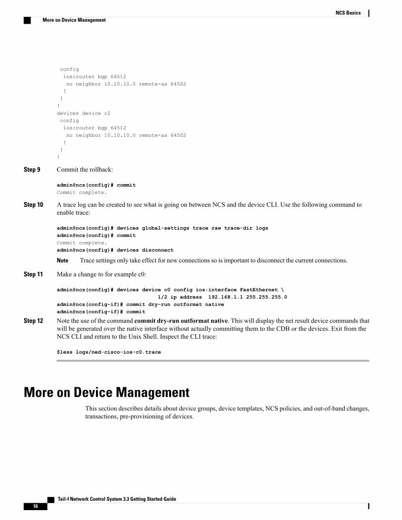
Step 9 Commit the rollback:
admin@ncs(config)# commitCommit complete.
Step 10 A trace log can be created to see what is going on between NCS and the device CLI. Use the following command toenable trace:
admin@ncs(config)# devices global-settings trace raw trace-dir logsadmin@ncs(config)# commitCommit complete.admin@ncs(config)# devices disconnect
Trace settings only take effect for new connections so is important to disconnect the current connections.Note
Step 11 Make a change to for example c0:
admin@ncs(config)# devices device c0 config ios:interface FastEthernet \1/2 ip address 192.168.1.1 255.255.255.0
admin@ncs(config-if)# commit dry-run outformat nativeadmin@ncs(config-if)# commit
Step 12 Note the use of the command commit dry-run outformat native. This will display the net result device commands thatwill be generated over the native interface without actually committing them to the CDB or the devices. Exit from theNCS CLI and return to the Unix Shell. Inspect the CLI trace:
$less logs/ned-cisco-ios-c0.trace
More on Device ManagementThis section describes details about device groups, device templates, NCS policies, and out-of-band changes,transactions, pre-provisioning of devices.
Tail-f Network Control System 3.3 Getting Started Guide16
NCS BasicsMore on Device Management

Creating Device GroupsAs seen above, ranges can be used to send configuration commands towards several devices. Device groupscan be created to allow for grouped actions that does not require naming conventions. A group can referenceany number of devices. A device can be part of any number of groups, and groups can be hierarchical.
The command sequence below creates a group of core devices and a group with all devices. Note that youcan use tab completion when adding the device names into the group. Also note that it requires configurationmode. (If you are still in the Unix Shell from the steps above, do $ncs_cli -C -u admin)
admin@ncs(config)# devices device-group core device-name [ c0 c1 ]admin@ncs(config-device-group-core)# commit
admin@ncs(config)# devices device-group all device-name c2 device-group coreadmin@ncs(config-device-group-all)# commit
admin@ncs(config)# show full-configuration devices device-groupdevices device-group alldevice-name [ c2 ]device-group [ core ]!devices device-group coredevice-name [ c0 c1 ]!
admin@ncs(config)# do show devices device-groupNAME MEMBER INDETERMINATES CRITICALS MAJORS MINORS WARNINGS-------------------------------------------------------------------------all [ c0 c1 c2 ] 0 0 0 0 0core [ c0 c1 ] 0 0 0 0 0
The "do show" which shows the operational data for the groups. Device groups has a member attributethat shows all member devices, flattening any group members.
Note
Device groups can contain different devices and devices from different vendors. Configuration changes willbe committed to each device in its native language without needing to be adjusted in NCS.
You can for example at this point use the group to check if all core are in sync:
admin@ncs# devices device-group core check-syncsync-result
device c0result in-sync
sync-result
device c1result in-sync
Device TemplatesAssume we would like to manage permit lists across devices. This can be achieved by defining templates andapply them to device groups. The following CLI sequence defines a tiny template, called community-list:
admin@ncs(config)# devices template community-list config ios:ip \community-list standard test1 \permit permit-list 64000:40
admin@ncs(config-permit-list-64000:40)# commit
Tail-f Network Control System 3.3 Getting Started Guide 17
NCS BasicsCreating Device Groups

Commit complete.admin@ncs(config-permit-list-64000:40)# top
admin@ncs(config)# show full-configuration devices templatedevices template community-listconfigios:ip community-list standard test1permit permit-list 64000:40!!!![ok][2013-08-09 11:27:28]
This can now be applied to a device group:
admin@ncs(config)# devices device-group core apply-template template-name community-listadmin@ncs(config)# show configurationdevices device c0configios:ip community-list standard test1 permit 64000:40!!devices device c1configios:ip community-list standard test1 permit 64000:40!!admin@ncs(config)# commit dry-run outformat nativedevice c0ip community-list standard test1 permit 64000:40
device c1ip community-list standard test1 permit 64000:40
admin@ncs(config)# commitCommit complete.
Defining Multi-vendor TemplatesSince the configuration is written in IOS, the above template would not work with Juniper devices. Templatescan be used on different device types (read NEDs) by using a prefix for the device model. The template wouldthen look like:
template community-list config junos:configuration ...ios:ip ...
The above indicates how NCS manages different models for different device-types. When NCS connects tothe devices the NEDs checks the device type and revision and returns that to NCS. This can be inspected(note, in operational mode):
admin@ncs# show devices device moduleNAME NAME REVISION FEATURES DEVIATIONS-------------------------------------------------------------------c0 tailf-ned-cisco-ios 2014-02-12 - -
tailf-ned-cisco-ios-stats 2014-02-12 - -c1 tailf-ned-cisco-ios 2014-02-12 - -
tailf-ned-cisco-ios-stats 2014-02-12 - -c2 tailf-ned-cisco-ios 2014-02-12 - -
tailf-ned-cisco-ios-stats 2014-02-12 - -
Tail-f Network Control System 3.3 Getting Started Guide18
NCS BasicsDevice Templates

So here we see that c0 uses a tailf-ned-cisco-ios module which tells NCS which data-model to use for thedevice. Every NED comes with a YANG data-model for the device. This renders the NCS data-store (CDB)schema, the NCS CLI, WebUI and southbound commands.
The model introduces namespace prefixes for every configuration item. This also resolves issues arounddifferent vendors using the same configuration command for different configuration elements. Note that everyitem is prefixed with ios:
admin@ncs# show running-config devices device c0 config ios:ip community-listdevices device c0configios:ip community-list 1 permitios:ip community-list 2 denyios:ip community-list standard s permitios:ip community-list standard test1 permit 64000:40!!
Another important question is how to control if the template shall merge the list or replace the list. This ismanaged via "tags". The default behavior of templates is to merge the configuration. Tags can be inserted atany point in the template. Tag values are merge, replace, delete, create, and nocreate.
Assume that c0 has the following configuration:
admin@ncs# show running-config devices device c0 config ios:ip community-listdevices device c0configios:ip community-list 1 permitios:ip community-list 2 denyios:ip community-list standard s permit
If we apply the template the default result would be:
admin@ncs# show running-config devices device c0 config ios:ip community-listdevices device c0configios:ip community-list 1 permitios:ip community-list 2 denyios:ip community-list standard s permitios:ip community-list standard test1 permit 64000:40!!
We could change the template in the following way to get a result where the permit list would be replacedrather than merged . When working with tags in templates it is often helpful to view the template as a treerather then a command view. The CLI has a display option for showing a curly-braces tree view that correspondsto the data-model structure rather then the command set. This makes it easier to see where to add tags.
admin@ncs(config)# show full-configuration devices templatedevices template community-listconfigios:ip community-list standard test1permit permit-list 64000:40!!!!admin@ncs(config)# show full-configuration devices template | display curly-bracestemplate community-list
config ios:ip
community-list standard test1
permit permit-list 64000:40;;
Tail-f Network Control System 3.3 Getting Started Guide 19
NCS BasicsDevice Templates

admin@ncs(config)# tag add devices template community-list config ios:ip \community-list replace
admin@ncs(config)# commitCommit complete.admin@ncs(config)# show full-configuration devices template | display curly-bracestemplate community-list
config ios:ip
/* Tags: replace */community-list
standard test1 permit
permit-list 64000:40;;
Different tags can be added across the template tree. If we now apply the template to device c0 which alreadyhave community lists the following happens:
admin@ncs(config)# show full-configuration devices device c0 config ios:ip community-listdevices device c0configios:ip community-list 1 permitios:ip community-list 2 denyios:ip community-list standard s permitios:ip community-list standard test1 permit 64000:40!!admin@ncs(config)# devices device c0 apply-template template-name community-listadmin@ncs(config)# show configurationdevices device c0configno ios:ip community-list 1 permitno ios:ip community-list 2 denyno ios:ip community-list standard s permit!!
Any existing values in the list are replaced in this case. The following tags are available:
• merge (default): the template changes will be merged with the existing template
• replace: the template configuration will be replaced by the new configuration
• create: the template will create those nodes which does not exist. If a node already exists this will resultin an error.
• nocreate: the merge will only affect configuration items that already exist in the template. It will nevercreate the configuration with this tag, or any associated commands inside it. It will only modify existingconfiguration structures.
• delete: delete anything from this point
Tail-f Network Control System 3.3 Getting Started Guide20
NCS BasicsDevice Templates

A template can have different tags along the tree nodes.Note
A problem with the above template is that every value is hard-coded. What if you wanted a template wherethe community-list name and permit-list values are variables passed to the template when applied? Any partof a template can be a variable, (or actually an XPATH expression). We can modify the template to usevariables in the following way:
1 Remove the previous template:
admin@ncs(config)# no devices template community-list config ios:ip \community-list standard test1
2 Add a new template:
admin@ncs(config)# devices template community-list config ios:ip \community-list standard $LIST-NAME permit \permit-list $AS
admin@ncs(config-permit-list-$AS)# commitCommit complete.
admin@ncs(config-permit-list-$AS)# topadmin@ncs(config)# show full-configuration devices templatedevices template community-listconfigios:ip community-list standard $LIST-NAMEpermit permit-list $AS!!!!
The template now requires two parameters when applied (tab completion will prompt for the variable):
admin@ncs(config)# devices device-group all apply-template \template-name community-list variable \ name LIST-NAME value 'test2' \variable name AS value '60000:30'
admin@ncs(config)# commit
The replace tag was still part of the template and it would delete any existing community lists, which isprobably not the desired outcome in the general case.
Note
The template mechanism described so far is "fire-and-forget". The templates does not have any memory ofwhat happened to the network, which devices they touched. A user can modify the templates without anythinghappening to the network until an explicit apply-template action is performed. (Templates are of course as allconfiguration changes done as a transaction). NCS also supports service templates that are more "advanced"in many ways, more information on this will be presented later in this guide.
PoliciesIn order to make sure that configuration is applied according to site or corporate rules you can use NCSpolicies. Policies are validated at every commit, they can be of type error that implies that the change cannotgo through or a warning which means that you have to confirm a configuration that gives a warning.
Tail-f Network Control System 3.3 Getting Started Guide 21
NCS BasicsPolicies

A policy is composed of:
1 Policy name2 Iterator: loop over a path in the model, for example all devices, all services of a specific type.3 Expression: a boolean expression that must be true for every node returned from the iterator, for example,
snmp must be turned on.4 Warning or error: a message displayed to the user. If it is of type warning the user can still commit the
change, if of type error the change cannot be made.
An example is shown below:
admin@ncs(config)# policy rule class-mapPossible completions:error-message Error message to print on expression failureexpr XPath 1.0 expression that returns a booleanforeach XPath 1.0 expression that returns a node setwarning-message Warning message to print on expression failure
admin@ncs(config)# policy rule class-map foreach /devices/device \expr config/ios:class-map[name='a'] \warning-message "Device name must have a class-map a"
admin@ncs(config-rule-class-map)# top
admin@ncs(config)# commitCommit complete.
admin@ncs(config)# show full-configuration policypolicy rule class-mapforeach /devices/deviceexpr config/ios:class-map[ios:name='a']warning-message "Device name must have a class-map a"!
Now if we try to delete a class-map 'a' we will get a policy violation.
admin@ncs(config)# no devices device c2 config ios:class-map match-all aadmin@ncs(config)# validateValidation completed with warnings:Device c2 must have a class-map a
admin@ncs(config)# commitThe following warnings were generated:Device c2 must have a class-map a
Proceed? [yes,no] yesCommit complete.
admin@ncs(config)# validateValidation completed with warnings:Device c2 must have a class-map a
The name variable refers to the node-set from the iterator. This node-set will be the list of devices in NCSand the devices have an attribute called 'name'.
In order to understand the syntax for the XPATH expressions in the policy a pipe-target in the CLI can beused that displays the XPATH expression for an item:
admin@ncs(config)# show full-configuration devices device c2 \config ios:class-map | display xpath
ncs:devices/ncs:device[ncs:name='c2']/ncs:config/ios:class-map[ios:name='cmap1']/ios:prematch match-all
...
Tail-f Network Control System 3.3 Getting Started Guide22
NCS BasicsPolicies

In order to debug policies look at the end of logs/xpath.trace. This file will show all validated XPATHexpressions and any errors.
4-Sep-2014::11:05:30.103 Evaluating XPath for policy: class-map:/devices/device
get_next(/ncs:devices/device) = c0XPath policy match: /ncs:devices/devicec0get_next(/ncs:devices/devicec0) = c1XPath policy match: /ncs:devices/devicec1get_next(/ncs:devices/devicec1) = c2XPath policy match: /ncs:devices/devicec2get_next(/ncs:devices/devicec2) = falseexists("/ncs:devices/devicec2/config/class-mapa") = trueexists("/ncs:devices/devicec1/config/class-mapa") = trueexists("/ncs:devices/devicec0/config/class-mapa") = true
Validation scripts can also be defined in Python. For more information about validation scripts, see sectionPlug and Play Scripts, on page 71.
Out-of-Band Changes
Detecting and Reconciling Out-of-band Changes
In reality, network engineers will still modify configurations using other tools like out of band CLI or othermanagement interfaces. It is important to understand how NCS handles this. The NCS network simulatorsupports CLI towards the devices. For example we can use the IOS CLI on say c0 and delete a permit-list.From the UNIX shell start a CLI session towards c0.
$ ncs-netsim cli-i c0
c0> enablec0# configureEnter configuration commands, one per line. End with CNTL/Z.
c0(config)# show full-configuration ip community-listip community-list standard test1 permitip community-list standard test2 permit 60000:30c0(config)# no ip community-list standard test2c0(config)#c0# exit
Start the NCS CLI again:
$ ncs_cli -C -u admin
NCS detects if its configuration copy in CDB differs from the configuration in the device. Various strategiesare used depending on device support;; transaction-ids, time-stamps, configuration hash-sums. For examplea NCS user can request a check-sync operation:
admin@ncs# devices check-syncsync-result
device c0result out-of-syncinfo got: e54d27fe58fda990797d8061aa4d5325 expected: 36308bf08207e994a8a83af710effbf0
sync-result
device c1result in-sync
sync-result
device c2result in-sync
Tail-f Network Control System 3.3 Getting Started Guide 23
NCS BasicsOut-of-Band Changes

admin@ncs# devices device-group core check-syncsync-result
device c0result out-of-syncinfo got: e54d27fe58fda990797d8061aa4d5325 expected: 36308bf08207e994a8a83af710effbf0
sync-result
device c1result in-sync
NCS can also compare the configurations with the CDB and show the difference:
admin@ncs# devices device c0 compare-configdiffdevices
device c0 config
ios:ip community-list
+ standard test1 + permit + + - standard test2 - permit - permit-list 60000:30;;- -
At this point we can choose if we want to use the configuration stored in the CDB as the valid configurationor the configuration on the device:
admin@ncs# devices sync-Possible completions:sync-from Synchronize the config by pulling from the devicessync-to Synchronize the config by pushing to the devices
admin@ncs# devices sync-to
In the above example we chose to overwrite the device configuration from NCS.
Resolving ConflictsNCS will also detect out-of-sync when committing changes. In the following scenario a local c0 CLI useradds an interface. To add an interface:
1 Modify the device using the device CLI:
$ ncs-netsim cli-i c0
admin connected from 127.0.0.1 using console on ADMIN-M-915Dc0> enablec0# configureEnter configuration commands, one per line. End with CNTL/Z.c0(config)# interface FastEthernet 1/0 ip address 192.168.1.1 255.255.255.0c0(config-if)#c0# exit
Tail-f Network Control System 3.3 Getting Started Guide24
NCS BasicsOut-of-Band Changes

2 Work with NCS CLI:
$ ncs_cli -C -u admin
admin@ncs# configEntering configuration mode terminal
admin@ncs(config)# devices device c0 config ios:interface \FastEthernet 1/1 ip address 192.168.1.1 255.255.255.0
admin@ncs(config-if)# commitAborted: Network Element Driver: device c0: out of sync
At this point we have two diffs:
1 The device and NCS CDB (devices device compare-config)2 The on-going transaction and CDB (show configuration)
admin@ncs(config)# devices device c0 compare-configdiffdevices
device c0 config
ios:interface FastEthernet 1/0
ip address
primary + mask 255.255.255.0;;+ address 192.168.1.1;;
admin@ncs(config)# show configurationdevices device c0configios:interface FastEthernet1/1ip address 192.168.1.1 255.255.255.0exit!!
To resolve this you can choose to synchronize the configuration between the devices and the CDB beforecommitting. There is also an option to over-ride the out-of-sync check:
admin@ncs(config)# commit no-out-of-sync-check
or
admin@ncs(config)# devices global-settings out-of-sync-commit-behaviourPossible completions:accept reject
As noted before, all changes are applied as complete transactions of all configurations on all of the devices.Either all configuration changes are completed successfully or all changes are removed entirely. Consider asimple case where one of the devices is not responding. For the transaction manager an error response from
Tail-f Network Control System 3.3 Getting Started Guide 25
NCS BasicsOut-of-Band Changes

a device or a non-responding device are both errors and the transaction should automatically rollback to thestate before the commit command was issued.
Stop c0:
$ ncs-netsim stop c0DEVICE c0 STOPPED
Go back to the NCS CLI and perform a configuration change over c0 and c1:
admin@ncs(config)# devices device c0 config ios:ip community-list \standard test3 permit 50000:30
admin@ncs(config-config)# devices device c1 config ios:ip community-list \standard test3 permit 50000:30
admin@ncs(config-config)# topadmin@ncs(config)# show configurationdevices device c0configios:ip community-list standard test3 permit 50000:30!!devices device c1configios:ip community-list standard test3 permit 50000:30!!
admin@ncs(config)# commitAborted: Failed to connect to device c0: connection refused: Connection refusedadmin@ncs(config)# *** ALARM connection-failure: Failed to connect todevice c0: connection refused: Connection refused
NCS sends commands to all devices in parallel, not sequentially. If any of the devices fails to accept thechanges or reports an error, NCS will issue a rollback to the other devices. Note, this works also fornon-transactional devices like IOS CLI and SNMP. This works even for non-symmetrical cases where therollback command sequence is not just the reverse of the commands. NCS does this by treating the rollbackas it would any other configuration change. NCS can use the current configuration and previous configurationand generate the commands needed to rollback from the configuration changes.
The diff configuration is still in the private CLI session, it can be restored, modified (if the error was due tosomething in the config), or in some cases, fix the device.
NCS is not a "best effort" configuration management system. The error reporting coupled with the ability tocompletely rollback failed changes to the devices, ensures that the configurations stored in the CDB and theconfigurations on the devices are always consistent and that no failed or "orphan" configurations are left onthe devices.
First of all, if the above was not a multi-device transaction, meaning that the change should be appliedindependently device per device, then it is just a matter of performing the commit between the devices.
Second, NCS has a commit flag "async-commit-queue" or "sync-commit-queue". Commit queues shouldprimarily be used for performance reasons when there is a high throughput of incoming configuration changes.Atomic transactions comes with a cost, the critical section of the data-store is locked per in the final piece ofcommit in each transaction. So, in cases where there are northbound systems of NCS that generates manysimultaneous large configuration changes these might get queued. Commit queues will send the devicecommands as separate transactions, so the lock is much shorter. If any device fails an alarm will be raised.
admin@ncs(config)# commit async-commit-queuecommit-queue-id 2236633674Commit complete.
admin@ncs(config)# do show devices commit-queues
Tail-f Network Control System 3.3 Getting Started Guide26
NCS BasicsOut-of-Band Changes

KILOBYTES WAITING TRANSIENT
ID AGE STATUS SIZE DEVICES FOR ERRORS DONE-------------------------------------------------------------------------2236633674 11 blocking 1 [ c1 c0 ] - [ c0 ] [ c1]Go to the UNIX shell and start the device and monitor the commit queues.
$ncs-netsim start c0DEVICE c0 OK STARTED
$ ncs_cli -C -u admin
admin connected from 127.0.0.1 using console on ADMIN-M-915Dadmin@ncs# show devices commit-queues
KILOBYTES WAITING TRANSIENT
ID AGE STATUS SIZE DEVICES FOR ERRORS DONE-------------------------------------------------------------------------2236633674 92 blocking 1 [ c1 c0 ] - [ c0 ] [ c1 ]
admin@ncs# show devices commit-queuesKILOBYTES WAITING TRANSIENT
ID AGE STATUS SIZE DEVICES FOR ERRORS DONE-------------------------------------------------------------------------2236633674 94 blocking 1 [ c1 c0 ] - [ c0 ] [ c1 ]
...
admin@ncs# show devices commit-queues% No entries found.
Devices can also be pre-provisioned, this means that the configuration can be prepared in NCS and pushedto the device when it is available. To illustrate this we can start by adding a new device to NCS that is notavailable in the network simulator:
admin@ncs(config)# devices device c3 address 127.0.0.1 port 10030 \authgroup default device-type cli \ned-id cisco-ios
admin@ncs(config-device-c3)# state admin-state southbound-lockedadmin@ncs(config-device-c3)# commit
Above we added a new device to NCS with IP address local host and port 10030. This device does not existin the network simulator. We can tell NCS not to send any commands southbound by setting the admin-stateto southbound-locked (actually the default). This means that all configuration changes will succeed, theresult will be stored in CDB. At any point in time when the device is available in the network the state canbe changed and the complete configuration pushed to the new device. The CLI sequence below also illustratesa powerful copy configuration command which can copy any configuration from one device to another. Thefrom and to paths are separated by the keyword to.
admin@ncs(config)# copy cfg merge devices device c0 config \ios:ip community-list to \devices device c3 config ios:ip community-list
admin@ncs(config)# show configurationdevices device c3configios:ip community-list standard test2 permit 60000:30ios:ip community-list standard test3 permit 50000:30!!
admin@ncs(config)# commit
admin@ncs(config)# devices check-sync...
Tail-f Network Control System 3.3 Getting Started Guide 27
NCS BasicsOut-of-Band Changes

sync-result device c3result locked
Conflict ResolutionDifferent users or management tools can of course run parallel sessions to NCS. All on-going sessions havea logical copy of CDB. An important case needs to be understood if there is a conflict when multiple usersattempt to modify the same device configuration at the same time with different changes. First lets look at theCLI sequence below, user admin to the left, user Joe to the right.
admin@ncs(config)# devices device c0 config \ios:snmp-server community fozbar
joe@ncs(config)# devices device c0 config \ios:snmp-server community fezbar
admin@ncs(config-config)# commit
System message at 2014-09-04 13:15:19...Commit performed by admin via console using cli.
joe@ncs(config-config)# commitjoe@ncs(config)# show full-configuration devices device c0 config ios:snmp-serverdevices device c0configios:snmp-server community fezbarios:snmp-server community fozbar
!!
There is no conflict in the above sequence, community is a list so both Joe and admin can add items to thelist. Note that user Joe gets information about user admin committing.
On the other hand if two users modifies a single item that is not a list the following happens:
admin@ncs(config)# devices device c0 config ios:power redundancy-mode redundant
joe@ncs(config)# devices device c0 config ios:power redundancy-mode combined
admin@ncs% commit
System message at 2014-09-04 13:23:10...Commit performed by admin via console using cli.
joe@ncs% commitjoe@ncs(config-config)# commitAborted: there are conflicts.--------------------------------------------------------------------------Resolve needed before configuration can be committed. View conflicts withthe command 'show configuration' and execute the command 'resolved' when done,or exit configuration mode to abort.Conflicting configuration items are indicated with a leading '!'Conflicting users: admin--------------------------------------------------------------------------joe@ncs(config)# show configurationdevices device c0config
! ios:power redundancy-mode combined!
!
joe@ncs(config)# resolved
Tail-f Network Control System 3.3 Getting Started Guide28
NCS BasicsConflict Resolution

joe@ncs(config)# commitCommit complete.
In this case Joe commits a change to redundancy-mode after admin and a conflict resolution process starts.Joe can see the value set by admin and his own value and choose resolution.
Tail-f Network Control System 3.3 Getting Started Guide 29
NCS BasicsConflict Resolution

Tail-f Network Control System 3.3 Getting Started Guide30
NCS BasicsConflict Resolution

C H A P T E R 4Network Element Drivers and Adding Devices
Network Element Drivers, NEDs, provides the connectivity between NCS and the devices. NEDs are installedas NCS packages. For information on how to add a package for a new device type, see section Packages,on page 107.
To see the list of installed packages (you will not see the F5 BigIP ):
admin@ncs# show packagespackages package cisco-iospackage-version 3.0description "NED package for Cisco IOS"ncs-min-version [ 3.0.2 ]directory ./state/packages-in-use/1/cisco-ioscomponent upgrade-ned-idupgrade java-class-name com.tailf.packages.ned.ios.UpgradeNedIdcomponent cisco-iosned cli ned-id cisco-iosned cli java-class-name com.tailf.packages.ned.ios.IOSNedClined device vendor Cisco
NAME VALUE---------------------show-tag interface
oper-status uppackages package f5-bigippackage-version 1.3description "NED package for the F5 BigIp FW/LB"ncs-min-version [ 3.0.1 ]directory ./state/packages-in-use/1/bigipcomponent f5-bigipned generic java-class-name com.tailf.packages.ned.bigip.BigIpNedGenericned device vendor F5oper-status up!The core parts of a NED are:
1 Data-Model : independent of underlying device interface technology NEDs come with a data-model inYANG that specifies configuration data and operational data that is supported for the device. For nativeNETCONF devices the YANG comes from the device, for JunOS NCS generates the model from theJunOS XML schema, for SNMP devices NCS generates the model from the MIBs. For CLI devices theNED designer wrote the YANG to map the CLI.
NCS only cares about the data that is in the model for the NED. The rest is ignored. See the NEDdocumentation to learn more about what is covered for the NED.
Tail-f Network Control System 3.3 Getting Started Guide 31

2 Code: for NETCONF and SNMP devices there is no code. For CLI devices there is a minimum of codemanaging connecting over ssh/telnet and looking for version strings. The rest is auto-rendered from thedata-model.
There are four categories of NEDs depending on the device interface:
1 NETCONF NED: the device supports NETCONF, for example Juniper.2 CLI NED: any device with a CLI that resembles a Cisco CLI. This is used for most CLI based devices
like Alcatel-Lucent, Ericsson, Force10, etc.3 Generic NED: proprietary protocols like REST, non-Cisco CLIs.4 SNMP NED: a SNMP device.
This chapter contains the following sections:
• Device Authentication, page 32
• Connecting Devices for Different NED Types, page 33
• Administrative State for Devices, page 35
• Trouble-shooting NEDs, page 36
Device AuthenticationEvery device needs an authgroup that tells NCS how to authenticate to the device:
admin@ncs(config)# show full-configuration devices authgroupsdevices authgroups group defaultumap adminremote-name adminremote-password $4$wIo7Yd068FRwhYYI0d4IDw==!umap operremote-name operremote-password $4$zp4zerM68FRwhYYI0d4IDw==!!devices authgroups snmp-group defaultdefault-map community-name publicumap adminusm remote-name adminusm security-level auth-privusm auth md5 remote-password $4$wIo7Yd068FRwhYYI0d4IDw==usm priv des remote-password $4$wIo7Yd068FRwhYYI0d4IDw==!!The CLI snippet above shows that there is a mapping from NCS users admin and oper to the remote user andpassword to be used on the devices. There are two options, either a mapping from local user to remote useror to pass the credentials. Below is a CLI example to create a new authgroup foobar and map NCS user Joe:
admin@ncs(config)# devices authgroups group foobar umap joe same-pass same-useradmin@ncs(config-umap-joe)# commitThis authgroup will pass on Joe's credentials to the device.
There is a similar structure for SNMP devices authgroups snmp-group that supports SNMPv1/v2c, andSNMPv3 authentication. The SNMP authgroup above has a default authgroup for not mapped users.
Tail-f Network Control System 3.3 Getting Started Guide32
Network Element Drivers and Adding DevicesDevice Authentication

Connecting Devices for Different NED TypesMake sure you know the authentication information and created authgroups as above. Also try all informationlike port numbers, authentication information, and that you can read and set the configuration, before tryingfrom NCS. For example CLI, if it is a CLI NED. So, if it is a CLI device, try to ssh (or telnet) to the device,and do show and set configuration.
All devices have a admin-state with default value southbound-locked. This means that if you do not setthis value to unlocked no commands will be sent to the device.
CLI NEDsAdding a Cisco IOS device to NCS is described below:
(See also examples.ncs/getting-started/using-ncs/2-real-device-cisco-ios). Straightforward, addinga new device on a specific address, standard ssh port:
admin@ncs(config)# devices device c7 address 1.2.3.4 port 22 device-type cli ned-id cisco-iosadmin@ncs(config-device-c7)# authgroupPossible completions:default foobar
admin@ncs(config-device-c7)# authgroup defaultadmin@ncs(config-device-c7)# state admin-state unlockedadmin@ncs(config-device-c7)# commit
NETCONF NED for JunOSAdding JunOS devices to NCS is described below:
See also /examples.ncs/getting-started/using-ncs/3-real-device-juniper. Make sure that NETCONFover SSH is enabled on the JunOS device:
junos1% show system servicesftp;;ssh;;telnet;;netconf
ssh port 22;;
Then you can create a NCS NETCONF device as follows:
admin@ncs(config)# devices device junos1 address junos1.lab port 22 authgroup foobar \device-type netconf
admin@ncs(config-device-junos1)# state admin-state unlockedadmin@ncs(config-device-junos1)# commit
SNMP NEDsBy default all read-only objects are mapped to operational data in NCS and read-write objects are mapped toconfiguration data. This means that a sync-from operation will load read-write objects into NCS. We havepreviously explained that all configuration data for a device is available in CDB at the path
Tail-f Network Control System 3.3 Getting Started Guide 33
Network Element Drivers and Adding DevicesConnecting Devices for Different NED Types

/devices/device/config. Read-only objects are available at /devices/device/live-status. This path willretrieve the data directly from the device and not via CDB. Read-only objects can be live counters for exampleand therefore they must be read live from the device. This is true for all NEDs and not only SNMP.
admin@ncs# show devices device r1 live-status SNMPv2-MIBlive-status SNMPv2-MIB system sysDescr "Tail-f ConfD agent - r1"live-status SNMPv2-MIB system sysObjectID 1.3.6.1.4.1.24961live-status SNMPv2-MIB system sysUpTime 4253live-status SNMPv2-MIB system sysContact ""live-status SNMPv2-MIB system sysName ""live-status SNMPv2-MIB system sysLocation ""live-status SNMPv2-MIB system sysServices 72live-status SNMPv2-MIB system sysORLastChange 0live-status SNMPv2-MIB snmp snmpInPkts 3live-status SNMPv2-MIB snmp snmpInBadVersions 0live-status SNMPv2-MIB snmp snmpInBadCommunityNames 0live-status SNMPv2-MIB snmp snmpInBadCommunityUses 0live-status SNMPv2-MIB snmp snmpInASNParseErrs 0live-status SNMPv2-MIB snmp snmpEnableAuthenTraps disabledlive-status SNMPv2-MIB snmp snmpSilentDrops 0live-status SNMPv2-MIB snmp snmpProxyDrops 0live-status SNMPv2-MIB snmpSet snmpSetSerialNo 2161860In many cases SNMP NEDs are used for reading operational data in parallel with a CLI NED for writing andreading configuration data. More on that later.
Before trying NCS use net-snmp command line tools or your favorite SNMP Browser to try that all settingsare ok.
Adding a SNMP device assuming the NED is in place:
admin@ncs(config)# show full-configuration devices device r1devices device r1address 127.0.0.1port 11023device-type snmp version v2cdevice-type snmp snmp-authgroup defaultstate admin-state unlocked!admin@ncs(config)# show full-configuration devices device r2devices device r2address 127.0.0.1port 11024device-type snmp version v3device-type snmp snmp-authgroup defaultdevice-type snmp mib-group [ basic snmp ]state admin-state unlocked!MIB Groups are important. A MIB group is just a named collection of SNMP MIB Modules. If you do notspecify any MIB group for a device, NCS will try with all known MIBs. It is possible to create MIB groupswith wild-cards such as CISCO*.
admin@ncs(config)# show full-configuration devices mib-groupdevices mib-group basicmib-module [ BASIC-CONFIG-MIB ]!devices mib-group snmpmib-module [ SNMP* ]!(See also examples.ncs/snmp-ned/basic/README.)
Tail-f Network Control System 3.3 Getting Started Guide34
Network Element Drivers and Adding DevicesSNMP NEDs

Generic NEDsGeneric devices are typically configured like a CLI device. Make sure you set the right address, port, protocoland authentication information.
Below follows an example to setup NCS with F5 BigIP:
admin@ncs(config)# devices device bigip01 address 192.168.1.162 \port 22 device-type generic ned-id f5-bigip
admin@ncs(config-device-bigip01)# state admin-state southbound-lockedadmin@ncs(config-device-bigip01)# authgroupPossible completions:default foobar
admin@ncs(config-device-bigip01)# authgroup defaultadmin@ncs(config-device-bigip01)# commit
Multi-NED DevicesAssume you have a Cisco device that you would like NCS to configure over CLI but read statistics overSNMP. This can be achieved by adding settings for "live-device-protocol":
admin@ncs(config)# devices device c0 live-status-protocol snmp \device-type snmp version v1 \snmp-authgroup default mib-group [ snmp ]
admin@ncs(config-live-status-protocol-snmp)# commit
admin@ncs(config)# show full-configuration devices device c0devices device c0address 127.0.0.1port 10022!authgroup defaultdevice-type cli ned-id cisco-ioslive-status-protocol snmpdevice-type snmp version v1device-type snmp snmp-authgroup defaultdevice-type snmp mib-group [ snmp ]!Device c0 have a config tree from the CLI NED and a live-status tree (read-only) from the SNMP NED usingall MIBs in group snmp.
Administrative State for DevicesDevices have an admin-state with following values:
• unlocked: the device can be modified and changes will be propagated to the real device.
• southbound-locked: the device can be modified but changes will be not be propagated to the real device.Can be used to prepare configurations before the device is available in the network.
• locked: the device can only be read.
Tail-f Network Control System 3.3 Getting Started Guide 35
Network Element Drivers and Adding DevicesGeneric NEDs

The admin-state value southbound-locked is default. This means if you create a new device without explicitlysetting this value configuration changes will not propagate to the network. To see default values use the pipetarget details.admin@ncs(config)# show full-configuration devices device c0 | details
Trouble-shooting NEDsIn order to analyze NED problems, turn on the tracing for a device and look at the trace file contents.
admin@ncs(config)# show full-configuration devices global-settings \devices global-settings trace-dir ./logs
admin@ncs(config)# devices device c0 trace rawadmin@ncs(config-device-c0)# commit
admin@ncs(config)# devices device c0 disconnectadmin@ncs(config)# devices device c0 connectNCS pools ssh connections and trace settings are only affecting new connections so therefore any openconnectionmust be closed before the trace setting will take effect. Now you can inspect the raw communicationbetween NCS and the device:
$ less logs/ned-c0.trace
admin connected from 127.0.0.1 using ssh on SVALLIN-M-915Dc0>*** output 8-Sep-2014::10:05:39.673 ***
enable
*** input 8-Sep-2014::10:05:39.674 ***enablec0#*** output 8-Sep-2014::10:05:39.713 ***
terminal length 0
*** input 8-Sep-2014::10:05:39.714 ***terminal length 0c0#*** output 8-Sep-2014::10:05:39.782 ***
terminal width 0
*** input 8-Sep-2014::10:05:39.783 ***terminal width 00^Mc0#*** output 8-Sep-2014::10:05:39.839 ***
-- Requesting version string --show version
*** input 8-Sep-2014::10:05:39.839 ***show versionCisco IOS Software, 7200 Software (C7200-JK9O3S-M), Version 12.4(7h), RELEASE SOFTWARE(fc1)^MTechnical Support: http://www.cisco.com/techsupport^MCopyright (c) 1986-2007 by Cisco Systems, Inc.^M...
If NCS fails in talking to the device the typical root causes are:
1 Timeout problems : some devices are slow to respond, latency on connections etc. Fine-tune the connect,read and write timeouts for the device:
admin@ncs(config)# devices device c0Possible completions:
Tail-f Network Control System 3.3 Getting Started Guide36
Network Element Drivers and Adding DevicesTrouble-shooting NEDs

...connect-timeout - Timeout in seconds for new connections...read-timeout - Timeout in seconds used when reading data...write-timeout - Timeout in seconds used when writing data
These settings can be set in profiles shared by devices.
admin@ncs(config)# devices profiles profile good-profilePossible completions:connect-timeout Timeout in seconds for new connectionsned-settings Control which device capabilities NCS usesread-timeout Timeout in seconds used when reading datatrace Trace the southbound communication to deviceswrite-timeout Timeout in seconds used when writing data
2 Device management interface problems: examples, not enabled the NETCONF ssh subsystem on Juniper,not enabled the SNMP agent, using wrong port numbers etc. Use stand-alone tools to make sure you canconnect, read configuration and write configuration over the device interface that NCS is using
3 Access rights: the NCS mapped user does not have access rights to do the operation on the device. Makesure the authgroups settings are ok, test themmanually to read andwrite configuration with those credentials.
4 NED data-model and device version problems: if the device is upgraded and existing commands actuallychange in an incompatible way the NED has to be updated. This can be done by editing the YANGdata-model for the device or by using Tail-f support.
Tail-f Network Control System 3.3 Getting Started Guide 37
Network Element Drivers and Adding DevicesTrouble-shooting NEDs

Tail-f Network Control System 3.3 Getting Started Guide38
Network Element Drivers and Adding DevicesTrouble-shooting NEDs

C H A P T E R 5Managing Network Services
Up until this point, this guide has described how to use NCS to configure devices. NCS can also manage thelife-cycle for services like VPNs, BGP peers, ACLs. It is important to understand what is meant by servicein this context.
1 NCS abstracts the device specific details. The user only needs to enter attributes relevant to the service.
2 The service instance has configuration data itself that can be represented and manipulated.
3 A service instance configuration change is applied to all affected devices.
These are the features NCS uses to support service configuration.
1 Service Modeling: network engineers can model the service attributes and the mapping to deviceconfigurations. For example, this means that a network engineer can specify a data-model for VPNs withrouter interfaces, VLAN ID, VRF and route distinguisher.
2 Service life-cycle: while less sophisticated configuration management systems can only create an initialservice instance in the network they do not support changing or deleting a service instance. With NCSyou can at any point in time modify service elements like the VLAN ID of a VPN and NCS can generatethe corresponding changes to the network devices.
3 The NCS service instance has configuration data that can be represented and manipulated. The servicemodel run-time updates all NCS northbound interfaces so a network engineer can view and manipulatethe service instance over CLI, WebUI, REST etc.
4 NCS maintains references between service instances and device configuration. This means that a VPNinstance knows exactly which device configurations it created/modified. Every configuration stored inthe CDB is mapped to the service instance that created it.
This chapter contains the following sections:
• A Service Example, page 40
• Running the Example, page 42
• Service-Life Cycle Management, page 44
• Defining Your Own Services, page 49
• Reconciling Existing Services, page 59
• Brown-field Networks, page 60
Tail-f Network Control System 3.3 Getting Started Guide 39
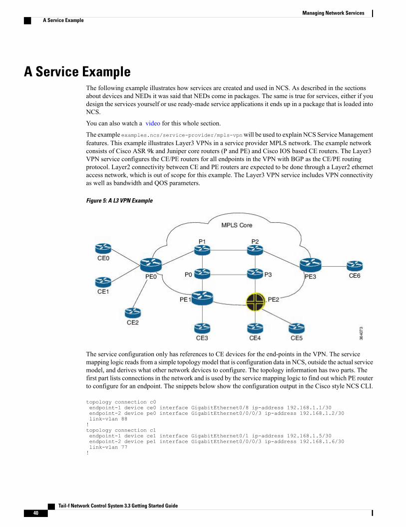
A Service ExampleThe following example illustrates how services are created and used in NCS. As described in the sectionsabout devices and NEDs it was said that NEDs come in packages. The same is true for services, either if youdesign the services yourself or use ready-made service applications it ends up in a package that is loaded intoNCS.
You can also watch a video for this whole section.
The example examples.ncs/service-provider/mpls-vpnwill be used to explain NCS ServiceManagementfeatures. This example illustrates Layer3 VPNs in a service provider MPLS network. The example networkconsists of Cisco ASR 9k and Juniper core routers (P and PE) and Cisco IOS based CE routers. The Layer3VPN service configures the CE/PE routers for all endpoints in the VPN with BGP as the CE/PE routingprotocol. Layer2 connectivity between CE and PE routers are expected to be done through a Layer2 ethernetaccess network, which is out of scope for this example. The Layer3 VPN service includes VPN connectivityas well as bandwidth and QOS parameters.
Figure 5: A L3 VPN Example
The service configuration only has references to CE devices for the end-points in the VPN. The servicemapping logic reads from a simple topology model that is configuration data in NCS, outside the actual servicemodel, and derives what other network devices to configure. The topology information has two parts. Thefirst part lists connections in the network and is used by the service mapping logic to find out which PE routerto configure for an endpoint. The snippets below show the configuration output in the Cisco style NCS CLI.
topology connection c0endpoint-1 device ce0 interface GigabitEthernet0/8 ip-address 192.168.1.1/30endpoint-2 device pe0 interface GigabitEthernet0/0/0/3 ip-address 192.168.1.2/30link-vlan 88!topology connection c1endpoint-1 device ce1 interface GigabitEthernet0/1 ip-address 192.168.1.5/30endpoint-2 device pe1 interface GigabitEthernet0/0/0/3 ip-address 192.168.1.6/30link-vlan 77!
Tail-f Network Control System 3.3 Getting Started Guide40
Managing Network ServicesA Service Example

The second part lists devices for each role in the network and is in this example only used to dynamicallyrender a network map in the Web UI.
topology role cedevice [ ce0 ce1 ce2 ce3 ce4 ce5 ]!topology role pedevice [ pe0 pe1 pe2 pe3 ]!
QOS configuration in service provider networks is complex, and often require a lot of different variations. Itis also often desirable to be able to deliver different levels of QOS. This example shows how a QOS policyconfiguration can be stored in NCS and be referenced from VPN service instances. Three different levels ofQOS policies are defined;; GOLD, SILVER and BRONZE with different queueing parameters.
qos qos-policy GOLDclass BUSINESS-CRITICALbandwidth-percentage 20!class MISSION-CRITICALbandwidth-percentage 20!class REALTIMEbandwidth-percentage 20priority!!qos qos-policy SILVERclass BUSINESS-CRITICALbandwidth-percentage 25!class MISSION-CRITICALbandwidth-percentage 25!class REALTIMEbandwidth-percentage 10!
Three different traffic classes are also defined with a DSCP value that will be used inside the MPLS corenetwork as well as default rules that will match traffic to a class.
qos qos-class BUSINESS-CRITICALdscp-value af21match-traffic sshsource-ip anydestination-ip anyport-start 22port-end 22protocol tcp!!qos qos-class MISSION-CRITICALdscp-value af31match-traffic call-signalingsource-ip anydestination-ip anyport-start 5060port-end 5061protocol tcp!!
Tail-f Network Control System 3.3 Getting Started Guide 41
Managing Network ServicesA Service Example
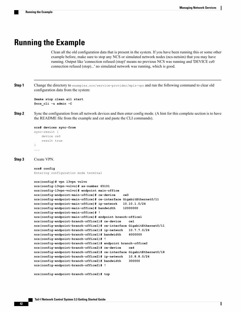
Running the ExampleClean all the old configuration data that is present in the system. If you have been running this or some otherexample before, make sure to stop any NCS or simulated network nodes (ncs-netsim) that you may haverunning. Output like 'connection refused (stop)' means no previous NCS was running and 'DEVICE ce0connection refused (stop)...' no simulated network was running, which is good.
Step 1 Change the directory to examples.ncs/service-provider/mpls-vpn and run the following command to clear oldconfiguration data from the system:
$make stop clean all start$ncs_cli -u admin -C
Step 2 Sync the configuration from all network devices and then enter config mode. (A hint for this complete section is to havethe README file from the example and cut and paste the CLI commands).
ncs# devices sync-fromsync-result
device ce0result true
...
Step 3 Create VPN.
ncs# configEntering configuration mode terminal
ncs(config)# vpn l3vpn volvoncs(config-l3vpn-volvo)# as-number 65101ncs(config-l3vpn-volvo)# endpoint main-officencs(config-endpoint-main-office)# ce-device ce0ncs(config-endpoint-main-office)# ce-interface GigabitEthernet0/11ncs(config-endpoint-main-office)# ip-network 10.10.1.0/24ncs(config-endpoint-main-office)# bandwidth 12000000ncs(config-endpoint-main-office)# !ncs(config-endpoint-main-office)# endpoint branch-office1ncs(config-endpoint-branch-office1)# ce-device ce1ncs(config-endpoint-branch-office1)# ce-interface GigabitEthernet0/11ncs(config-endpoint-branch-office1)# ip-network 10.7.7.0/24ncs(config-endpoint-branch-office1)# bandwidth 6000000ncs(config-endpoint-branch-office1)# !ncs(config-endpoint-branch-office1)# endpoint branch-office2ncs(config-endpoint-branch-office2)# ce-device ce4ncs(config-endpoint-branch-office2)# ce-interface GigabitEthernet0/18ncs(config-endpoint-branch-office2)# ip-network 10.8.8.0/24ncs(config-endpoint-branch-office2)# bandwidth 300000ncs(config-endpoint-branch-office2)# !
ncs(config-endpoint-branch-office2)# top
Tail-f Network Control System 3.3 Getting Started Guide42
Managing Network ServicesRunning the Example

ncs(config)# show configurationvpn l3vpn volvoas-number 65101endpoint branch-office1ce-device ce1ce-interface GigabitEthernet0/11ip-network 10.7.7.0/24bandwidth 6000000!endpoint branch-office2ce-device ce4ce-interface GigabitEthernet0/18ip-network 10.8.8.0/24bandwidth 300000!endpoint main-officece-device ce0ce-interface GigabitEthernet0/11ip-network 10.10.1.0/24bandwidth 12000000!!
ncs(config)# commit dry-run outformat nativedevice ce0interface GigabitEthernet0/11description volvo local networkip address 10.10.1.1 255.255.255.0exit
...
(config)# commit
Step 4 Add another VPN (prompts ommitted):
top
!vpn l3vpn fordas-number 65200endpoint main-officece-device ce2ce-interface GigabitEthernet0/5ip-network 192.168.1.0/24bandwidth 10000000!endpoint branch-office1ce-device ce3ce-interface GigabitEthernet0/5ip-network 192.168.2.0/24bandwidth 5500000!
Tail-f Network Control System 3.3 Getting Started Guide 43
Managing Network ServicesRunning the Example
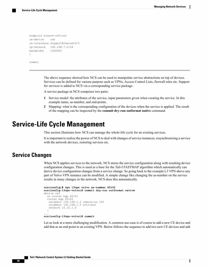
endpoint branch-office2ce-device ce5ce-interface GigabitEthernet0/5ip-network 192.168.7.0/24bandwidth 1500000!
commit
The above sequence showed how NCS can be used to manipulate service abstractions on top of devices.Services can be defined for various purpose such as VPNs, Access Control Lists, firewall rules etc. Supportfor services is added to NCS via a corresponding service package.
A service package in NCS comprises two parts:
1 Service model: the attributes of the service, input parameters given when creating the service. In thisexample name, as-number, and end-points.
2 Mapping: what is the corresponding configuration of the devices when the service is applied. The resultof the mapping can be inspected by the commit dry-run outformat native command.
Service-Life Cycle ManagementThis section illustrates how NCS can manage the whole-life cycle for an existing services.
It is important to realize the power of NCS to deal with changes of service instances, resynchronizing a servicewith the network devices, restoring services etc.
Service ChangesWhen NCS applies services to the network, NCS stores the service configuration along with resulting deviceconfiguration changes. This is used as a base for the Tail-f FASTMAP algorithm which automatically canderive device configuration changes from a service change. So going back to the example L3 VPN above anypart of Volvo VPN instance can be modified. A simple change like changing the as-number on the serviceresults in many changes in the network. NCS does this automatically.
ncs(config)# vpn l3vpn volvo as-number 65102ncs(config-l3vpn-volvo)# commit dry-run outformat nativedevice ce0no router bgp 65101router bgp 65102neighbor 192.168.1.2 remote-as 100neighbor 192.168.1.2 activatenetwork 10.10.1.0!
...ncs(config-l3vpn-volvo)# commit
Let us look at a more challenging modification. A common use-case is of course to add a new CE device andadd that as an end-point to an existing VPN. Below follows the sequence to add two new CE devices and add
Tail-f Network Control System 3.3 Getting Started Guide44
Managing Network ServicesService-Life Cycle Management

them to the VPNs. (In the CLI snippets below we omit the prompt to enhance readability). First we add themto the topology.
top!topology connection c7endpoint-1 device ce7 interface GigabitEthernet0/1 ip-address 192.168.1.25/30endpoint-2 device pe3 interface GigabitEthernet0/0/0/2 ip-address 192.168.1.26/30link-vlan 103!topology connection c8endpoint-1 device ce8 interface GigabitEthernet0/1 ip-address 192.168.1.29/30endpoint-2 device pe3 interface GigabitEthernet0/0/0/2 ip-address 192.168.1.30/30link-vlan 104!ncs(config)#commit
Note that the above just updates NCS local information on topological links. It has no effect on the network.The mapping for the L3 VPN services does a look-up in the topology connections to find the correspondingpe router.
Then we add them to the VPNs:
top!vpn l3vpn fordendpoint new-branch-officece-device ce7ce-interface GigabitEthernet0/5ip-network 192.168.9.0/24bandwidth 4500000!vpn l3vpn volvoendpoint new-branch-officece-device ce8ce-interface GigabitEthernet0/5ip-network 10.8.9.0/24bandwidth 4500000!
Before we send anything to the network, lets see look at the device configuration using dry-run. As you cansee, both new CE devices are connected to the same PE router, but for different VPN customers.
ncs(config)#commit dry-run outformat native
And commit the configuration to the network:
(config)#commit
Service Impacting Out-of-Band ChangesNCS can be used to check if the service configuration in the network is up to date. In a new terminal windowwe connect directly to the device ce0 that is a Cisco device emulated by the tool ncs-netsim.
1 Modify a device.
$ncs-netsim cli-c ce0
We will now reconfigure an edge interface that we previously configured using NCS.
ce0> enablece0# configure
Tail-f Network Control System 3.3 Getting Started Guide 45
Managing Network ServicesService Impacting Out-of-Band Changes

Enter configuration commands, one per line. End with CNTL/Z.ce0(config)# no policy-map volvoce0(config)# exitce0# exit
2 Restore the service.
From the NCS terminal, check the status of the network configuration:
ncs# devices check-syncsync-result
device ce0result out-of-syncinfo got: c5c75ee593246f41eaa9c496ce1051ea expected: c5288cc0b45662b4af88288d29be8667
...
ncs# vpn l3vpn * check-syncvpn l3vpn ford check-sync
in-sync truevpn l3vpn volvo check-sync
in-sync true
ncs# vpn l3vpn * deep-check-syncvpn l3vpn ford deep-check-sync
in-sync truevpn l3vpn volvo deep-check-sync
in-sync false
The CLI sequence above performs three different comparisons:
• Real device configuration versus device configuration copy in NCS CDB
• Expected device configuration from service perspective and device configuration copy in CDB.
• Expected device configuration from service perspective and real device configuration.
Notice that the service 'volvo' is out of sync from the service configuration. Use the check-sync outformat clito see what the problem is:
ncs# vpn l3vpn volvo deep-check-sync outformat clicli
device name ce0data devices
device ce0 config
+ ios:policy-map volvo + class class-default + shape + average + bit-rate 12000000;;+ + + +
Assume that a network engineer considers the real device configuration to be the master:
ncs# devices device ce0 sync-fromresult true
Tail-f Network Control System 3.3 Getting Started Guide46
Managing Network ServicesService Impacting Out-of-Band Changes

And then restore the service:
ncs# vpn l3vpn volvo re-deploy dry-run outformat native native
device name ce0data policy-map volvo
class class-defaultshape average 12000000!!
ncs# vpn l3vpn volvo re-deploy
Service DeletionIn the same way as NCS can calculate any service configuration change it can also automatically delete thedevice configurations that resulted from creating services:
ncs(config)# no vpn l3vpn fordncs(config)# commit dry-rundevice ce7
config - ios:policy-map ford - class class-default - shape - average - bit-rate 4500000;;- - - -
...
Finally, commit the changes to delete the service.(config)# commit
Viewing Service ConfigurationsService instances live in the NCS data-store as well as a copy of the device configurations. NCS will maintainrelationships between these two.
The following command shows the configuration for a service:
ncs(config)# show full-configuration vpn l3vpnvpn l3vpn volvoas-number 65102endpoint branch-office1ce-device ce1ce-interface GigabitEthernet0/11ip-network 10.7.7.0/24bandwidth 6000000!...
Showing the service in the operational mode gives the following output:
ncs# show vpn l3vpn
Tail-f Network Control System 3.3 Getting Started Guide 47
Managing Network ServicesService Deletion

vpn l3vpn volvodevice-modifications devices
device ce0 config
+ ios:policy-map volvo + class class-default + shape + average + bit-rate 12000000;;+ + + +
...
Note that operational mode in the CLI was used above. Every service instance has an operational attributethat is maintained by the transaction manager and shows which device configuration it created.
You can also view list all devices that are touched by a service and vice versa:
ncs# show vpn l3vpn device-listNAME DEVICE LIST----------------------------------------volvo [ ce0 ce1 ce4 ce8 pe0 pe2 pe3 ]
ncs# show devices device service-listNAME SERVICE LIST-------------------------------------ce0 [ "/l3vpn:vpn/l3vpnvolvo" ]ce1 [ "/l3vpn:vpn/l3vpnvolvo" ]ce2 [ ]ce3 [ ]ce4 [ "/l3vpn:vpn/l3vpnvolvo" ]ce5 [ ]ce6 [ ]ce7 [ ]ce8 [ "/l3vpn:vpn/l3vpnvolvo" ]p0 [ ]p1 [ ]p2 [ ]p3 [ ]pe0 [ "/l3vpn:vpn/l3vpnvolvo" ]pe1 [ ]pe2 [ "/l3vpn:vpn/l3vpnvolvo" ]pe3 [ "/l3vpn:vpn/l3vpnvolvo" ]
Furthermore, every device configuration has backwards pointers to the corresponding service instances:
ncs(config)# show full-configuration devices device ce3 config | display service-meta-datadevices device ce3config.../* Refcount: 1 *//* Backpointer: [ /l3vpn:vpn/l3vpn:l3vpn[l3vpn:name='ford'] ] */ios:interface GigabitEthernet0/2.100/* Refcount: 1 */description Link to PE / pe1 - GigabitEthernet0/0/0/5/* Refcount: 1 */encapsulation dot1Q 100/* Refcount: 1 */ip address 192.168.1.13 255.255.255.252/* Refcount: 1 */service-policy output fordexit
ncs(config)# show full-configuration devices device ce3 config \| display curly-braces | display service-meta-data
...
Tail-f Network Control System 3.3 Getting Started Guide48
Managing Network ServicesViewing Service Configurations

ios:interface GigabitEthernet 0/1;;GigabitEthernet 0/10;;GigabitEthernet 0/11;;GigabitEthernet 0/12;;GigabitEthernet 0/13;;GigabitEthernet 0/14;;GigabitEthernet 0/15;;GigabitEthernet 0/16;;GigabitEthernet 0/17;;GigabitEthernet 0/18;;GigabitEthernet 0/19;;GigabitEthernet 0/2;;/* Refcount: 1 *//* Backpointer: [ /l3vpn:vpn/l3vpn:l3vpn[l3vpn:name='ford'] ] */GigabitEthernet 0/2.100
/* Refcount: 1 */description "Link to PE / pe1 - GigabitEthernet0/0/0/5";;encapsulation
dot1Q /* Refcount: 1 */vlan-id 100;;
ip
address primary
/* Refcount: 1 */address 192.168.1.13;;/* Refcount: 1 */mask 255.255.255.252;;
service-policy
/* Refcount: 1 */output ford;;
ncs(config)# show full-configuration devices device ce3 config \| display service-meta-data | context-match Backpointer
devices device ce3/* Refcount: 1 *//* Backpointer: [ /l3vpn:vpn/l3vpn:l3vpn[l3vpn:name='ford'] ] */ios:interface GigabitEthernet0/2.100
devices device ce3/* Refcount: 2 *//* Backpointer: [ /l3vpn:vpn/l3vpn:l3vpn[l3vpn:name='ford'] ] */ios:interface GigabitEthernet0/5
The reference counter above makes sure that NCSwill not delete shared resources until the last service instanceis deleted. The context-match search is helpful, it displays the path to all matching configuration items.
Defining Your Own ServicesIn order to have NCS deploy services across devices, two parts are needed:
1 A service model in YANG: the service model shall define the black-box view of a service;; which are theinput parameters given when creating the service? This YANG model will render an update of all NCSnorthbound interfaces, for example the CLI.
2 Mapping, given the service input parameters, what is the resulting device configuration? This mappingcan be defined in templates, code or a combination of both.
Tail-f Network Control System 3.3 Getting Started Guide 49
Managing Network ServicesDefining Your Own Services

Defining the Service ModelThe first step is to generate a skeleton package for a service. For details on packages see section Packages,on page 107. In order to reuse an existing environment for NCS and netsim we will reuse theexamples.ncs/getting-started/using-ncs/1-simulated-cisco-ios/ example. Make sure you havestopped any running NCS and netsim.
Step 1 Navigate to the simulated IOS directory and create a new package for the VLAN service model:
$cd examples.ncs/getting-started/using-ncs/1-simulated-cisco-ios/packages
Step 2 Create the template skeleton by using the ncs-make-package utility:
$ ncs-make-package --service-skeleton template-based vlan
This results in a directory structure:
vlanload-dirpackage-meta-data.xmlsrctemplates
The contents of the src/yang/vlan.yang file is:
module vlan
namespace "http://com/example/vlan";;prefix vlan;;
import ietf-inet-types prefix inet;;
import tailf-ncs prefix ncs;;
augment /ncs:services list vlan key name;;
uses ncs:service-data;;ncs:servicepoint "vlan";;
leaf name type string;;
// may replace this with other ways of refering to the devices.
Tail-f Network Control System 3.3 Getting Started Guide50
Managing Network ServicesDefining the Service Model

leaf-list device type leafref path "/ncs:devices/ncs:device/ncs:name";;
// replace with your own stuff hereleaf dummy type inet:ipv4-address;;
If this is your first exposure to YANG you can see that the modeling language is very straightforward and easy tounderstand. See RFC 6020 for more details and examples for YANG. The concepts to understand in the above generatedskeleton are:
1 The vlan service list will be augmented into the services tree in NCS. This specifies the path to reach vlans in theCLI, REST etc. There is no requirements on where the service shall be added into ncs, if you want vlans to be in thetop (in the CLI for example), just remove the augments statement.
2 The two lines of uses ncs:service-data and ncs:servicepoint "vlan" tells NCS that this is a service. This willbe explained more later in the document.
Step 3 Adjust the service model to represent the parameters you would like to enter when creating a VLAN.A very simple service model would look like below (modify the src/yang/vlan.yang file):
augment /ncs:services list vlan key name;;
uses ncs:service-data;;ncs:servicepoint "vlan";;leaf name type string;;
leaf vlan-id type uint32 range "1..4096";;
list device-if key "device-name";;leaf device-name type leafref path "/ncs:devices/ncs:device/ncs:name";;
leaf interface-type type enumeration
Tail-f Network Control System 3.3 Getting Started Guide 51
Managing Network ServicesDefining the Service Model

enum FastEthernet;;enum GigabitEthernet;;enum TenGigabitEthernet;;
leaf interface type string;;
This simple VLAN service model says:
1 We give a VLAN a name, for example net-1, this must also be unique, it is specified as "key".2 The VLAN has an ID from 1 to 40963 The VLAN is attached to a list of devices and interfaces. In order to make this example as simple as possible the
interface reference is selected by picking the type and then the name as a plain string.
The good thing with NCS is that already at this point you could load the service model to NCS and try if it works wellin the CLI etc. Nothing would happen to the devices since we have not defined the mapping, but this is normally theway to iterate a model, test the CLI towards the network engineers.
Step 4 To build this service model cd to$NCS_DIR/examples.ncs/getting-started/using-ncs/1-simulated-cisco-ios/packages/vlan/src and typemake(assuming you have the make build system installed).
$ make.../ncsc `ls vlan-ann.yang > /dev/null 2>&1 && echo "-a vlan-ann.yang"` \
-c -o ../load-dir/vlan.fxs yang/vlan.yangyang/vlan.yang:6: warning: imported module ietf-inet-types not used
Step 5 Go to the root directory of the simulated-ios example:
$ cd $NCS_DIR/examples.ncs/getting-started/using-ncs/1-simulated-cisco-ios
Step 6 Start netsim, NCS and the NCS CLI:
$ncs-netsim start$ncs --with-package-reload$ncs_cli -C -u admin
When starting NCS above we give NCS a parameter to reload all packages so that our newly added vlan package isincluded. Packages can also be reloaded without starting and stopping NCS. At this point we have a service model forVLANs, but no mapping of VLAN to device configurations.
Step 7 Create a VLAN service:
admin@ncs# configEntering configuration mode terminaladmin@ncs(config)# services vlan net-0 vlan-id 1234 device-if c0 interface-type FastEthernet \
interface 1/0admin@ncs(config-device-if-c0)# topadmin@ncs(config)# show configurationservices vlan net-0
Tail-f Network Control System 3.3 Getting Started Guide52
Managing Network ServicesDefining the Service Model

vlan-id 1234device-if c0interface-type FastEthernetinterface 1/0!!admin@ncs(config)# services vlan net-0 vlan-id 1234 device-if c1 interface-type FastEthernet \
interface 1/0admin@ncs(config-device-if-c1)# topadmin@ncs(config)# show configurationservices vlan net-0vlan-id 1234device-if c0interface-type FastEthernetinterface 1/0!device-if c1interface-type FastEthernetinterface 1/0!!admin@ncs(config)#admin@ncs(config)# commit dry-run outformat nativeadmin@ncs(config)# commitCommit complete.admin@ncs(config)# no services vlanadmin@ncs(config)# commitCommit complete.
Committing service changes has no effect on the devices since the mapping is not defined. The service instance data isstored in NCS CDB.
Note that you get tab completion on the devices since they are leafrefs to device names in CDB, the same for interface-typesince the types are enumerated in the model. However the interface name is just a string, and you have to type the correctinterface-name. For service-models where there is only one device-type like in this simple example, we could have useda reference to the ios interface name according to the IOS model. However that makes the service model dependant onthe underlying device types and if another type is added, the service model needs to be updated and this is most oftennot desired. There are techniques to get tab completion even when the data-type is string, but this is omitted here forsimplicity.
Step 8 Make sure you delete the VLAN service instance before moving on with the example.
Defining the MappingAfter defining the service model, define the mapping from service configuration to actual device configuration.
Step 1 To understand the actual device configuration, hard-wire the VLAN towards a device as an example.
Tail-f Network Control System 3.3 Getting Started Guide 53
Managing Network ServicesDefining the Mapping

This concrete device configuration is a boiler-plate for the mapping, it shows the expected result of applying the service.The CLI sequence below creates an example VLAN configuration on c0. This is later used to create the correspondingtemplate.
admin@ncs(config)# devices device c0 config ios:vlan 1234admin@ncs(config-vlan)# topadmin@ncs(config)# devices device c0 config ios:interface FastEthernet 10/10 \
switchport trunk allowed vlan 1234admin@ncs(config-if)# topadmin@ncs(config)# show configurationdevices device c0configios:vlan 1234!ios:interface FastEthernet10/10switchport trunk allowed vlan 1234exit!!admin@ncs(config)# commitThe concrete configuration above has the interface and VLAN hard-wired.
Step 2 Convert this into a template. It is always recommended to start like above and create a concrete representation of theconfiguration the template shall create. Templates are device-configuration where parts of the config is represented asvariables. These kind of templates are represented as XML files. The CLI command shows the example VLANconfiguration from previous step as XML.
admin@ncs(config)# show full-configuration devices device c0 config ios:vlan | display xml<config xmlns="http://tail-f.com/ns/config/1.0"><devices xmlns="http://tail-f.com/ns/ncs"><device><name>c0</name><config><vlan xmlns="urn:ios"><vlan-list><id>1234</id>
</vlan-list></vlan></config>
</device></devices>
</config>
admin@ncs(config)# show full-configuration devices device c0 config ios:interface \FastEthernet 10/10 | display xml
<config xmlns="http://tail-f.com/ns/config/1.0"><devices xmlns="http://tail-f.com/ns/ncs"><device><name>c0</name><config><interface xmlns="urn:ios"><FastEthernet><name>10/10</name><switchport>
Tail-f Network Control System 3.3 Getting Started Guide54
Managing Network ServicesDefining the Mapping

<trunk><allowed><vlan><vlans>1234</vlans>
</vlan></allowed>
</trunk></switchport>
</FastEthernet></interface></config>
</device></devices>
</config>
Step 3 Now, we shall build that template. When the package was created a skeleton XML file was created inpackages/vlan/templates/vlan.xml. The contents of the skeleton template file is shown below.Modify this to manageVLANs.
<config-template xmlns="http://tail-f.com/ns/config/1.0"servicepoint="vlan">
<devices xmlns="http://tail-f.com/ns/ncs"><device><!--
Select the devices from some data structure in the servicemodel. In this skeleton the devices are specified in a leaf-list.Select all devices in that leaf-list:
--><name>/device</name><config><!--
Add device-specific parameters here.In this skeleton the service has a leaf "dummy";; use thatto set something on the device e.g.:<ip-address-on-device>/dummy</ip-address-on-device>
--></config>
</device></devices>
</config-template>
Step 4 Modify the template skeleton:
1 Specify the right path to the devices. In this case the devices are identified by /device-if/device-name (see the YANGservice model).
2 For each of those devices add the VLAN and change the specified interface configuration. Copy the XML configfrom the CLI and replace with variables:
<config-template xmlns="http://tail-f.com/ns/config/1.0"servicepoint="vlan">
<devices xmlns="http://tail-f.com/ns/ncs"><device>
Tail-f Network Control System 3.3 Getting Started Guide 55
Managing Network ServicesDefining the Mapping

<name>/device-if/device-name</name><config><vlan xmlns="urn:ios"><vlan-list tags="merge"><id>../vlan-id</id>
</vlan-list></vlan><interface xmlns="urn:ios"><FastEthernet tags="nocreate" when="interface-type='FastEthernet'"><name>interface</name><switchport><trunk><allowed><vlan tags="merge"><vlans>../vlan-id</vlans>
</vlan></allowed>
</trunk></switchport>
</FastEthernet><GigabitEthernet tags="nocreate" when="interface-type='GigabitEthernet'"><name>interface</name><switchport><trunk><allowed><vlan tags="merge"><vlans>../vlan-id</vlans>
</vlan></allowed>
</trunk></switchport>
</GigabitEthernet><TenGigabitEthernet tags="nocreate" when="interface-type='TenGigabitEthernet'"><name>interface</name><switchport><trunk><allowed><vlan tags="merge"><vlans>../vlan-id</vlans>
</vlan></allowed>
</trunk></switchport>
</TenGigabitEthernet></interface>
</config></device>
</devices></config-template>
Step 5 For every /device-if/device-name from the service model do the following:
1 Add the vlan to the vlan-list, the tag merge tells the template to merge the data into an existing list (default is replaced).
Tail-f Network Control System 3.3 Getting Started Guide56
Managing Network ServicesDefining the Mapping

2 For every interface within that device, add the vlan to the allowed vlans and set mode to trunk. The tag "nocreate"tells the template to not create the named interface if it does not exist.
It is important to understand that every path in the template above refers to paths from the service model in vlan.yang.
Step 6 Request NCS to reload the packages:
admin@ncs# packages reloadreload-result
package cisco-iosresult true
reload-result
package vlanresult true
Step 7 Create a VLAN service:
admin@ncs(config)# services vlan net-0 vlan-id 1234 device-if c0 interface-type \FastEthernet interface 1/0
admin@ncs(config-device-if-c0)# topadmin@ncs(config)# services vlan net-0 device-if c1 interface-type FastEthernet interface 1/0admin@ncs(config-device-if-c1)# topadmin@ncs(config)# show configurationservices vlan net-0vlan-id 1234device-if c0interface-type FastEthernetinterface 1/0!device-if c1interface-type FastEthernetinterface 1/0!!admin@ncs(config)# commit dry-run outformat nativedevice c0interface FastEthernet1/0switchport trunk allowed vlan 1234exit
device c1vlan 1234!interface FastEthernet1/0switchport trunk allowed vlan 1234exit
admin@ncs(config)# commitCommit complete.
Step 8 Change the VLAN service:
admin@ncs(config)# services vlan net-0 vlan-id 1222admin@ncs(config-vlan-net-0)# top
Tail-f Network Control System 3.3 Getting Started Guide 57
Managing Network ServicesDefining the Mapping
admin@ncs(config)# show configurationservices vlan net-0vlan-id 1222!admin@ncs(config)# commit dry-run outformat nativedevice c0no vlan 1234vlan 1222!interface FastEthernet1/0switchport trunk allowed vlan 1222exit
device c1no vlan 1234vlan 1222!interface FastEthernet1/0switchport trunk allowed vlan 1222exit
It is important to understand what happens above. When the VLAN ID is changed, NCS is able to calculate the minimalrequired changes to the configuration. The same situation holds true for changing elements in the configuration or evenparameters of those elements. In this way NCS does not need to explicit mapping to define a VLAN change or deletion.NCS does not overwrite a new configuration on the old configuration. Adding an interface to the same service worksthe same:
admin@ncs(config)# services vlan net-0 device-if c2 interface-type FastEthernet interface 1/0admin@ncs(config-device-if-c2)# topadmin@ncs(config)# commit dry-run outformat nativedevice c2vlan 1222!interface FastEthernet1/0switchport trunk allowed vlan 1222exit
admin@ncs(config)# commitCommit complete.
Step 9 Clean up the configuration on the devices, run the delete command as shown below:
admin@ncs(config)# no services vlan net-0admin@ncs(config)# commit dry-run outformat nativedevice c0no vlan 1222interface FastEthernet1/0no switchport trunk allowed vlan 1222exit
device c1no vlan 1222interface FastEthernet1/0no switchport trunk allowed vlan 1222exit
device c2no vlan 1222
Tail-f Network Control System 3.3 Getting Started Guide58
Managing Network ServicesDefining the Mapping

interface FastEthernet1/0no switchport trunk allowed vlan 1222exit
admin@ncs(config)# commitCommit complete.
To make the VLAN service package complete edit the package-meta-data.xml to reflect the service modelpurpose. This example showed how to use template-based mapping. NCS also allows for programmaticmapping and also a combination of the two approaches. The latter is very flexible, if some logic need to beattached to the service provisioning that is expressed as templates and the logic applies device agnostictemplates.
Reactive FASTMAPFASTMAP is the NCS algorithm that renders any service change from the single definition of the createservice. As seen above, the template or code only has to define how the service shall be created, NCS is thencapable of defining any change from that single definition.
A limitation in the scenarios described sofar is that the mapping definition could immediately do its work asa single atomic transaction. This is sometimes not possible. Typical examples are: external allocation ofresource such as IP addresses from an IPAM, spinning up VMs, and sequencing in general.
Reactive FASTMAP addresses these scenarios. The general idea is that the create definition does not onlywrite device configuration but also state data for the service. An external process subscribes to that state dataand performs the side-effects. The external process will then call service redeploy which will run the createmethod again, checking available states like allocated IP address, running VM etc.
The example in getting-started/developing-with-ncs/4-rfs-service has a package calledvlan-reactive-fastmap that implements external allocation of a unit and a vlan-id for the service to illustratethis concept.
Reconciling Existing ServicesA very common situation when we wish to deploy NCS in an existing network is that the network alreadyhas existing services implemented in the network. These services may have been deployedmanually or throughan other provisioning system. The task is to introduce NCS, import the existing services into NCS. The goalis to use NCS to manage existing services, and to add additional instances of the same service type, usingNCS. This is a non-trivial problem since existing services may have been introduced in various ways. Evenif the service configuration has been done consistently it resembles the challenges of a general solution forrendering a corresponding C-program from assembler.
One of the prerequisites for this to work is that it is possible to construct a list of the already existing services.Maybe such a list exists in an inventory system, an external database, or maybe just an Excel spreadsheet. Itmay also be the case that we can:
1 Import all managed devices into NCS.2 Execute a full sync-from on the entire network.3 Write a program that traverses the entire network configuration and computes the services list.
Tail-f Network Control System 3.3 Getting Started Guide 59
Managing Network ServicesReactive FASTMAP

The first thing we must do when we wish to reconcile existing services is to define the service YANG model.The second thing is to implement the service mapping logic, and do it in such a way that given the serviceinput parameters, when we run the service code, they would all result in configuration that is already there inthe existing network.
The basic principles for reconciliation is:
1 Read the device configuration to NCS using the sync-from action. This will get the device configurationthat is a result of any existing services.
2 Instantiate the services according to the principles above.
Performing the above actions with the default behavior would not render the correct reference counters sinceNCS did not create the original configuration. The service activation can be run with dedicated flags to takethis into account. See the NCS User Guide for a detailed process.
Brown-field NetworksIn many cases a service activation solution like NCS is deployed in parallell with existing activation solutions.It is then desirable to make sure that NCS does not conflict with the device configuration rendered from theexisting solution.
NCS has a commit-flag that will restrict the device configuration to not overwrite data that NCS did not create:commit no-overwrite.
Tail-f Network Control System 3.3 Getting Started Guide60
Managing Network ServicesBrown-field Networks

C H A P T E R 6Compliance Reporting
When the unexpected happens or things come to the worst and the network configuration is broken, there isa need to gather information and verify the configuration.
NCS has numerous functions to show different aspects of such a network config verification. However, tosimplify this task, the compliance reporting can assemble information using a selection of these NCS functionsand present the resulting information in one report. The aim for this report is to answer two fundamentalquestions:
• Who has done what?
• Is the network correctly configured?
• What defines then a correctly configured network?
• Where is the master?
NCS by nature, with the configurations stored in CDB, is the master. Checking the live devices against theNCS stored device configuration is a fundamental part of compliance reporting. But it does not stop here.Compliance reporting can also be based on one or a number of stored device templates which the live devicesare compared against. The compliance reports can also be a combination of both approaches.
Compliance verification can be defined to check the current situation or checking historic events, or both.To assemble historic events, rollback files and audit logs are used. Therefore these functionalities must havebeen enabled for the time period of interest, or else no history view can be presented.
The reports can be formatted either as text, html or docbook xml format. The intention of the docbook formatis that the user can take the report and by further post-processing create reports formatted by own choice,for instance PDF using Apache FOP.
This chapter contains the following sections:
• Creating Compliance Report Definitions, page 62
• Running Reports, page 62
• Understanding Reports, page 63
Tail-f Network Control System 3.3 Getting Started Guide 61

Creating Compliance Report DefinitionsIt is possible to create several named compliance report definitions. Each named report defines which devices,services and/or templates that the configuration should be checked for.
The CLI command below shows a very simple definition (if you start theexamples.ncs/service-provider/mpls-vpn the following example is displayed):
ncs(config)# show full-configuration compliancecompliance reports report Compliance-Auditdevice-check all-devicesdevice-check current-out-of-sync truedevice-check historic-changes truedevice-check historic-out-of-sync trueservice-check all-servicesservice-check current-out-of-sync trueservice-check historic-out-of-sync truecompare-template snmp1 Pvariable COMMUNITYvalue 'public'!!compare-template snmp1 PEvariable COMMUNITYvalue 'public'!!!
This definition says that the "Compliance-Audit" audit will do a check-sync for all devices and services whenthe report is executed. It also includes historical entries from the NCS audit log indicating that the same devicesand services have been out of sync.
The report also specifies that the template named snmp1 shall be compared with all devices in the device-groupcalled P using the template variable value "COMMUNITY=public".
Running ReportsA named report can be executed and takes the following parameters when run:
1 Title: a title for this saved report.2 From - To: time window for entries from audit log, for example failed check-sync.
So the report defined above, daily-audit can be executed with:
ncs(config)# compliance reports report Compliance-Audit run \from 2014-09-01T00:00:00 title "ISO check" outformat html
id 1compliance-status violationsinfo Checking 17 devices and 2 serviceslocation http://localhost:8080/compliance-reports/report_1_admin_1_2014-9-14T15:10:21:0.html
Tail-f Network Control System 3.3 Getting Started Guide62
Compliance ReportingCreating Compliance Report Definitions
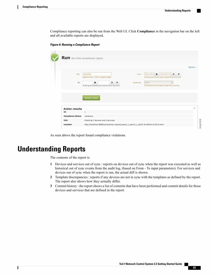
Compliance reporting can also be run from the Web UI. Click Compliance in the navigation bar on the leftand all available reports are displayed.
Figure 6: Running a Compliance Report
As seen above the report found compliance violations.
Understanding ReportsThe contents of the report is:
1 Devices and services out of sync : reports on devices out of sync when the report was executed as well ashistorical out of sync events from the audit log, (based on From - To input parameters). For services anddevices out of sync when the report is run, the actual diff is shown.
2 Template discrepancies : reports if any devices are not in sync with the templates as defined by the report.The report also shows how they actually differ.
3 Commit history : the report shows a list of commits that have been performed and commit details for thosedevices and services that are defined in the report.
Tail-f Network Control System 3.3 Getting Started Guide 63
Compliance ReportingUnderstanding Reports
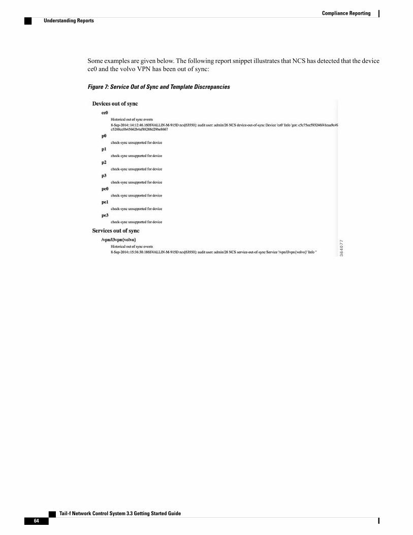
Some examples are given below. The following report snippet illustrates that NCS has detected that the devicece0 and the volvo VPN has been out of sync:
Figure 7: Service Out of Sync and Template Discrepancies
Tail-f Network Control System 3.3 Getting Started Guide64
Compliance ReportingUnderstanding Reports

The following example shows a summary of all commits. As a best practice usage of labels and commentsmakes the reports more useful. Also a summary of every commit for the specified devices and services areincluded in the report.
Figure 8: Commit History
All report runs are saved in a table and the report itself on disc.
Figure 9: Run Compliance Report
Tail-f Network Control System 3.3 Getting Started Guide 65
Compliance ReportingUnderstanding Reports

Tail-f Network Control System 3.3 Getting Started Guide66
Compliance ReportingUnderstanding Reports

C H A P T E R 7Scripting
Up to this point we have shown how to use the NCS CLIs and WebUI to perform configuration tasks. NCSprovides several northbound programmatic interfaces that a network engineer can use to automate tasks:
• CLI - since the NCS CLI represents the whole network you can develop CLI scripts to NCS rather thenindividual devices.
• REST - The rest interface provides the complete model available as http GET, PUT etc operations.The data is available as XML and JSON.
• NETCONF - this gives a transactional NETCONF view of the complete network. Scripts send sshXML Requests.
• JSON RPC - An API to build interactive Web Clients using JavaScript.
• MAAPI - MAAPI comes in several flavors, it is the general Management Agent API. MAAPI isavailable as command line utilities, C-API, Java API, and a Python API. This user guide will illustratethe Python API.
NCS also supports what are called "plug-and-play" scripts. Plug-and-play scripts can be dropped in a runningNCS system. The scripts will extend the CLI with new functions. Plug-and-play scripts are only availablein the NCS CLI. They are often implemented as shell scripts that calls MAAPI functions.
Also note that NCS can be used as a development platform to build custom networkmanagement applications.Programmable APIs are described in the NCS User Guide.
This chapter contains the following sections:
• NCS CLI Scripts, page 68
• NCS REST Scripts, page 68
• Python MAAPI Scripts, page 69
• NCS NETCONF Scripts, page 70
• Plug and Play Scripts, page 71
• Example Command Script, page 72
Tail-f Network Control System 3.3 Getting Started Guide 67

NCS CLI ScriptsA tiny script that displays the device configuration can be defined as:
#!/bin/shCLI="$NCS_DIR/bin/ncs_cli -C -u admin"$CLI <<EOFshow running-config devicesexitEOF
Save that into a file say show.sh. And run the script after making the file executable.
$chmod +x show.sh$./show.shBelow follows a simple shell script takes two parameters: device and community string and assigns the snmpcommunity string to the device.
#!/bin/shCLI="$NCS_DIR/bin/ncs_cli -C -u admin"
while [ $# -gt 0 ];; doarg="$1"shiftcase $arg in
--device)device="$1";; shift;;;;
--community)community="$1";; shift;;;;
esac doneif [ -z "$device" -o -z "$community" ];; then
echo "Need device name and community string";;exit 1;;
fi$CLI << EOFconfigdevices device $device config ios:snmp-server community $communitycommitexitexitEOF | grep "Commit complete"This script can be run as normal while passing the parameters for the device and the community string:
$ ./snmp.sh --device c1 --community foobar
NCS REST ScriptsIn order to use the REST interface it must be enabled in the ncs.conf file. The REST allows full support forCRUDX operations. Different resources like running database, operational data, actions, and rollbacks areavailable. The data can be fetched as XML or JSON. A top level get is shown below:
$ curl -v -u admin:admin http://localhost:8080/api...<api xmlns="http://tail-f.com/ns/rest" xmlns:y="http://tail-f.com/ns/rest"><version>0.5</version><config/><running/><operational/><operations/>
Tail-f Network Control System 3.3 Getting Started Guide68
ScriptingNCS CLI Scripts

<rollbacks/></api>* Connection #0 to host localhost left intactReading a specific resource:
$ curl -u admin:admin \http://localhost:8080/api/running/devices/device/c0/config/snmp-server
<snmp-server xmlns="urn:ios"y:self="/api/running/devices/device/c0/config/ios:snmp-server"...<community><name>public</name>
</community>...
</snmp-server>To replace a resource, save it to a file, modify the values in the file and replace it with PUT.
$ curl -v -u admin:admin \http://localhost:8080/api/running/devices/device/c0/config/snmp-server \> snmp-server.txt
$ open snmp-server.txtEDIT THE values....
$ curl -X PUT -T snmp-server.txt -u \admin:admin \http://localhost:8080/api/running/devices/device/c0/config/snmp-server
See a complete specification of the REST interface in the NCS User Guide.
Python MAAPI ScriptsMAAPI is fully documented asman pages, and NCS provides a Python binding. The example below showshow to connect to MAAPI open a session, start a transaction and set the description string of a device.
with ncs.maapi.wctx.connect() as c :with ncs.maapi.wctx.session(c, 'admin') as se :with ncs.maapi.wctx.trans(se, readWrite = ncs._constants.READ_WRITE) as t :t.set_elem('My Description', '/ncs:devices/devicec0/description')t.apply()
Below follows an example to create a service instance in Python. It assumes that the exampleexamples.ncs/service-provider/mpls-vpn is running.
import ncs
V = ncs.types.Value
def vpn_path(name) :return '/l3vpn:vpn/l3vpn"' + name + '"'
def create_service(t, name, asNumber) :path = vpn_path(name)
t.create_allow_exist(path)t.set_elem(V(asNumber, V.C_UINT32), path + '/as-number')
def add_endpoint(t, serviceName, endpointId, ceDevice, ceInterface, ipNetwork, bandwidth):
path = vpn_path(serviceName) + '/endpoint"' + endpointId + '"'
t.create_allow_exist(path)t.set_elem(ceDevice, path + '/ce-device')t.set_elem(ceInterface, path + '/ce-interface')t.set_elem(V(ipNetwork, V.C_IPV4PREFIX), path + '/ip-network')
Tail-f Network Control System 3.3 Getting Started Guide 69
ScriptingPython MAAPI Scripts
t.set_elem(V(bandwidth, V.C_UINT32), path + '/bandwidth')
def create_volvo(t) :serviceName = 'volvo'
create_service(t, serviceName, 12345)
add_endpoint(t, serviceName, 'branch-office1','ce1', 'GigabitEthernet0/11', '10.7.7.0/24', 6000000)
add_endpoint(t, serviceName, 'branch-office2','ce4', 'GigabitEthernet0/18', '10.8.8.0/24', 6000000)
add_endpoint(t, serviceName, 'main-office','ce0', 'GigabitEthernet0/11', '10.10.1.0/24', 6000000)
def sync_from_devices(maapiSock) :print('Syncing from devices ...')result = ncs._maapi.request_action(maapiSock,[], 0, fmt = '/ncs:devices/sync-from')print('Synced from devices!')
if __name__ == '__main__' :with ncs.maapi.wctx.connect(ip = '127.0.0.1', port = ncs._constants.NCS_PORT) as c :
with ncs.maapi.wctx.session(c, 'admin') as s :with ncs.maapi.wctx.trans(s, readWrite = ncs._constants.READ_WRITE) as t :
sync_from_devices(t.sock)create_volvo(t)t.apply()
NCS NETCONF ScriptsNCS also exposes a northbound NETCONF interface. The NETCONF protocol is specified in RFC 6241.Read the RFC to see the details. NCS comes with a command line tool netconf-console that can be used tosend NETCONF commands to NCS. It assumes paramiko ssh client is installed. For example, to read the c0config:
$ netconf-console -u admin -p admin --get -x "/devices/device[name='c0']"So from a shell script you can send any NETCONF request, for example like below:
#!/bin/shncsip="--host=127.0.0.1"ncsport="--port=2022"ncsuser="--user=admin"ncspass="--password=admin"
NC=$NCS_DIR/bin/netconf-console
$NC $ncsuser $ncspass $ncsip $ncsport - << HERE<?xml version="1.0" encoding="UTF-8"?><hello xmlns="urn:ietf:params:xml:ns:netconf:base:1.0"><capabilities><capability>urn:ietf:params:netconf:base:1.0</capability>
</capabilities></hello>] ]>] ]><?xml version="1.0" encoding="UTF-8"?><rpc xmlns="urn:ietf:params:xml:ns:netconf:base:1.0" message-id="1"><get-config xmlns:nc="urn:ietf:params:xml:ns:netconf:base:1.0"><source><running/>
</source><filter type="subtree"><ncs:devices xmlns:ncs="http://tail-f.com/ns/ncs">
<ncs:device>
Tail-f Network Control System 3.3 Getting Started Guide70
ScriptingNCS NETCONF Scripts

<ncs:name>c1</ncs:name><ncs:config><ios:router xmlns:ios="urn:ios"></ios:router>
</ncs:config></ncs:device>
</ncs:devices></filter>
</get-config></rpc>] ]>] ]><?xml version="1.0" encoding="UTF-8"?><rpc xmlns="urn:ietf:params:xml:ns:netconf:base:1.0" message-id="2"><close-session/>
</rpc>HEREEnd the NETCONF tags correctly, without space.
Plug and Play ScriptsWith the scripting mechanism it is possible for an end-user to add new functionality to NCS in a plug- and-playlike manner. No special tools are needed. There are two categories of scripts:
1 command scripts : are used to add new commands to the CLI.2 policy scripts : are invoked at validation time and may control the outcome of a transaction. Policy scripts
have the mandate to cause a transaction to abort.3 post-commit scripts : are invoked when a transaction has been committed. Post-commit scripts can for
example be used for logging, sending external events etc.
The terms "script" and "scripting" used throughout this description refer to how functionality can be addedwithout a requirement for integration using the NCS programming APIs. NCS will only run the scripts asUNIX executables. Thus they may be written as shell scripts, or using some other scripting language that issupported by the OS, or even be compiled code.
Scripts are stored in a directory tree with a predefined structure where there is a sub-directory for each scriptcategory:
scripts/command/policy/post-commit/
For some script categories it suffices to just add a script in the correct sub-directory in order to enable thescript. For others some configuration needs to be done. Scripts with a name beginning with a dot character('.') are ignored.
If you build a script that needs to query NCS for data or read information from the ongoing transaction etc,there are several NCS commands that can be used.
1 ncs-maapi : MAAPI is the general northbound API. It comes in different flavors. For shell scripts thecommand version is useful. For more information, seeman ncs-maapi.
2 ncs_load : Command line utility to load and save NCS configurations. For more information, seemanncs-load.
3 ncs_cmd : Command line utility that interfaces to common NCS library functions. For more information,seeman ncs_cmd.
The next example will illustrate this with a command script. For more info and examples of policy and commitscripts see the NCS User Guide .
Tail-f Network Control System 3.3 Getting Started Guide 71
ScriptingPlug and Play Scripts

Example Command ScriptAll scripts are required to provide a formal description of their interface. When the scripts are loaded NCSwill invoke the command script with: --command. The script must respond by writing its formal interfacedescription on stdout and exit normally. We will now illustrate this with a command script that adds a customcopy path function the NCS CLI. (Mimics the standard copy cfg command.)
#!/bin/sh
while [ $# -gt 0 ];; docase "$1" in
--h)usage=1;;;;
--command)cat << EOF
begin commandmodes: configstyles: c jcmdpath: cptreehelp: Copy a data container
end
begin paramname: frompresence: mandatoryhelp: fromend
begin paramname: topresence: mandatoryhelp: toendEOF
The above script interface specifies that the script can be reached in configuration mode and is supported inboth the Cisco and Juniper mode. The command will be called cptree and takes two mandatory parametersfrom and to.
The core part of the script then uses ncs_maapi to check that the given path parameters does exist in NCSand then finally uses the ncs_maapi copy-tree function.
ncs_maapi --exists $1 || echo "Missing path " $1;; exit 1 ;;ncs_maapi --exists $2 || echo "Missing path " $2;; exit 1 ;;ncs_maapi --copy-tree $2 $1
Scripts are automatically loaded at startup and may also be manually reloaded with the CLI command scriptreload.
Tail-f Network Control System 3.3 Getting Started Guide72
ScriptingExample Command Script

C H A P T E R 8The NCS Web User Interface
The Web UI gives access to all the functions described in this document. We will not repeat the wholedocument and show how to perform the tasks in the Web UI. The purpose of this section is just to illustratethe Web UI.
The Web UI is a mix of custom built widgets and auto-rendering from the underlying device and servicemodels. The latter gives the benefit that a Web UI is immediately updated when new devices or services areadded to the system. So, say you add support for a new device vendor. Without any programming is the NCSWeb UI capable of configuring those devices.
All major web browsers are supported and no plug-ins are required. The interface is a pure JavaScript Client.
This chapter contains the following sections:
• Using the Web UI, page 74
• Saving Transactions, page 75
Tail-f Network Control System 3.3 Getting Started Guide 73

Using the Web UITheWeb UI is available on port 8080 on the NCS server. The port can be changed in the ncs.conf file. A NCSuser must exist. After login the NCS dashboard is shown:
Figure 10: The NCS dashboard
The purpose of the dashboard is to give an overview of the network;; the devices, the services, device mapsalarms, logged in users, etc. All these are examples of widgets. In the example above the user has created twodashboards one home which shows devices and a device map and another 'admin' dashboard.
The devices widget allows the user to search devices, navigate to the configuration and modify any part ofthe device configuration. It also makes it easy to create and view device-groups. For example: drag a deviceinto a device group.
Tail-f Network Control System 3.3 Getting Started Guide74
The NCS Web User InterfaceUsing the Web UI

The figure below shows how to add widgets to a dashboard:
Figure 11: Adding widgets to a dashboard
Saving TransactionsTake special notice on the Save button, whenever that turns green a transaction has started and the data is notsaved to NCS datastore and pushed to the network until a user presses Save. Save also gives the option ifdry-run the changes before committing. In this way a user can modify several devices and apply them as onesingle transaction.
Figure 12: Save
Tail-f Network Control System 3.3 Getting Started Guide 75
The NCS Web User InterfaceSaving Transactions

Any network-wide change can be picked up as a rollback-file. That rollback can then be applied to undowhatever happened to the network:
Figure 13: Rollback files
Tail-f Network Control System 3.3 Getting Started Guide76
The NCS Web User InterfaceSaving Transactions
C H A P T E R 9Developing Service Applications
So far we have described how to use NCS as a tool to configure the network. Also we have shown how toautomate tasks by scripting using any of the northbound APIs. In this section we will illustrate how the NCSJava APIs can be used to extend the NCS system with new functionality.
Note that in order to automate tasks you can use the northbound APIs like REST, MAAPI (Python andC-bindings), or CLI scripting, see chapter Scripting, on page 67. This section is for extending the NCSsystemwith new features which will be automatically exposed over the north-bound APIs. The most commonuse-case is to implement network services that requires more advanced logic than can be expressed usingservice templates as shown in section Defining Your Own Services, on page 49.
This chapter contains the following sections:
• NCS Java VM and APIs, page 77
• Developing a Service, page 78
• Writing the Service Code, page 93
• Combining Java and Templates, page 98
NCS Java VM and APIsNCS runs as two processes: the NCS daemon and a Java VM. The NCS daemon contains the NCS core withCDB, the transaction engine, southbound NETCONF and SNMP, and the northbound APIs. The Java VMruns all java callback implementations, the Cisco CLI and Generic NED Java code, and the SNMPNotificationReceiver. Which java components that will run in an specific NCS installation is defined by the NCS packagesthat are available for this installation. By default NCS is configured to start and monitor the Java VM, butthis can be reconfigured to be another program or not controlled by the NCS daemon at all. All communicationbetween the NCS daemon and the Java VM is performed over tcp sockets.
The following is a list of the main Java APIs, (see the NCS User Guide for all APIs):
• MAAPI: The Management Agent API (MAAPI) provides a rich interface to the Transaction engine inNCS. Can read and write configuration data, and read operational data.
• CDB: CDB is the "reverse" of MAAPI, you can can read and write operational data, but only readconfiguration data. It also support subscription to changes in CDB.
Tail-f Network Control System 3.3 Getting Started Guide 77

• DP: The DP API makes it possible to create callback hooks, for example implementing actions onservices. We will see this later when we implement Java code for creating a service.
• NAVU: The NAVUAPI provides a DOM-like tree for all NCS services and devices. As a Java developeryou can navigate the DOM tree for the complete network without understanding the underlying modelformats and interfaces. The main features of the NAVU API is dynamic schema loading at start up andlazy loading of instance data.
The JavaDoc is available in your installation directory: doc/index.html.
Developing a ServiceThis section will illustrate how to implement a simple VLAN service in Java. The end-result will be the sameas shown in section Defining Your Own Services, on page 49 but this time implemented in Java instead oftemplates.
Note that the examples in this section are extremely simplified from a networking perspective in order toillustrate the concepts.
We will first look at the following preparatory steps:
1 Prepare a simulated environment of Cisco IOS devices: in this example we start from scratch in order toillustrate the complete development process. We will not reuse any existing NCS examples.
2 Generate a template service skeleton package: use NCS tools to generate a Java based service skeletonpackage.
3 Write and test the VLAN Service Model.4 Analyze the VLAN service mapping to IOS configuration.
The above steps are no different from defining services using templates. Next is to start playing with the JavaEnvironment:
1 Configuring start and stop of the Java VM.2 First look at the Service Java Code: introduction to service mapping in Java.3 Developing by tailing log files.4 Developing using Eclipse.
Setting Up the EnvironmentStart by setting up a run-time environment, that includes simulated Cisco IOS devices and configuration datafor NCS. Make sure you have sourced the ncsrc file.
Step 1 Create a directory:You can create the directory at any location. In this example, a new directory is created in the home directory.
$mkdir ~/vlan-service$cd ~/vlan-service
Tail-f Network Control System 3.3 Getting Started Guide78
Developing Service ApplicationsDeveloping a Service

Step 2 Create a simulated environment with three IOS devices and a NCS that is ready to run with this simulated network:
$ncs-netsim create-network $NCS_DIR/packages/neds/cisco-ios 3 c$ncs-setup --netsim-dir ./netsim/ --dest ./
Step 3 Start the simulator and NCS:
$ ncs-netsim startDEVICE c0 OK STARTEDDEVICE c1 OK STARTEDDEVICE c2 OK STARTED$ ncs
Step 4 Use the Cisco CLI towards one of the devices:
$ ncs-netsim cli-i c0admin connected from 127.0.0.1 using console on wallair.localc0> enablec0# configureEnter configuration commands, one per line. End with CNTL/Z.c0(config)# show full-configurationno service padno ip domain-lookupno ip http serverno ip http secure-serverip routingip source-routeip vrf my-forwardbgp next-hop Loopback 1!...
Step 5 Use the NCS CLI to get the configuration:
$ ncs_cli -C -u admin
admin connected from 127.0.0.1 using console on wallair.localadmin@ncs# devices sync-fromsync-result
device c0result true
sync-result
device c1result true
sync-result
device c2result true
admin@ncs# configEntering configuration mode terminal
admin@ncs(config)# show full-configuration devices device c0 config
Tail-f Network Control System 3.3 Getting Started Guide 79
Developing Service ApplicationsSetting Up the Environment

devices device c0configno ios:service padios:ip vrf my-forwardbgp next-hop Loopback 1!ios:ip community-list 1 permitios:ip community-list 2 denyios:ip community-list standard s permitno ios:ip domain-lookupno ios:ip http serverno ios:ip http secure-serverios:ip routing
...
Step 6 Set VLAN information manually on a device to prepare for the mapping later.
admin@ncs(config)# devices device c0 config ios:vlan 1234admin@ncs(config)# devices device c0 config ios:interface \
FastEthernet 1/0 switchport mode trunkadmin@ncs(config-if)# switchport trunk allowed vlan 1234admin@ncs(config-if)# top
admin@ncs(config)# show configurationdevices device c0configios:vlan 1234!ios:interface FastEthernet1/0switchport mode trunkswitchport trunk allowed vlan 1234exit!!
admin@ncs(config)# commit
Creating a Service PackageTo create a service package:
Step 1 View all the files in the run-time directory you have created:
$ ls -ltotal 32-rw-r--r-- 1 admin staff 628 Mar 3 13:13 README.ncs-rw-r--r-- 1 admin staff 1139 Mar 3 13:13 README.netsimdrwxr-xr-x 20 admin staff 680 Mar 3 13:45 logs
Tail-f Network Control System 3.3 Getting Started Guide80
Developing Service ApplicationsCreating a Service Package

drwxr-xr-x 6 admin staff 204 Mar 3 13:26 ncs-cdb-rw-r--r-- 1 admin staff 6708 Mar 3 13:13 ncs.confdrwxr-xr-x 5 admin staff 170 Mar 3 13:13 netsimdrwxr-xr-x 3 admin staff 102 Mar 3 13:13 packagesdrwxr-xr-x 4 admin staff 136 Mar 3 13:13 scriptsdrwxr-xr-x 5 admin staff 170 Mar 3 13:17 state
Step 2 Note the packages directory, cd to it:
$ cd packages/$ ls -ltotal 8cisco-ios -> .../packages/neds/cisco-ios
Currently there is only one package, the Cisco IOS NED.
Step 3 Create a new package that will contain the VLAN service.
$ ncs-make-package --service-skeleton java vlan$ lscisco-ios vlan
This creates a package with the following structure:
Figure 14: Package Structure Example
Tail-f Network Control System 3.3 Getting Started Guide 81
Developing Service ApplicationsCreating a Service Package

Creating a Service ModelModify the generated YANG skeleton service model to represent our definition of a VLAN service. To createa service model:
Step 1 Edit the vlan/src/yang/vlan.yang according to below:
augment /ncs:services list vlan key name;;
uses ncs:service-data;;ncs:servicepoint "vlan-servicepoint";;leaf name type string;;
leaf vlan-id type uint32 range "1..4096";;
list device-if key "device-name";;leaf device-name type leafref path "/ncs:devices/ncs:device/ncs:name";;
leaf interface type string;;
This simple VLAN service model says:
1 We give a VLAN a name, for example net-12 The VLAN has an ID from 1 to 40963 The VLAN is attached to a list of devices and interfaces. In order to make this example as simple as possible the
interface name is just a string. A more correct and useful example would specify this is a reference to an interface tothe device, but for now it is better to keep the example simple.
Step 2 Make sure you do keep the lines generated by the ncs-make-package:
uses ncs:service-data;;ncs:servicepoint "vlan-servicepoint";;The first line expands to a YANG structure that is shared amongst all services. The second line connects the service tothe Java callback.
Tail-f Network Control System 3.3 Getting Started Guide82
Developing Service ApplicationsCreating a Service Model

Step 3 Build this service model cd to packages/vlan/src and typemake (assuming you have the make build system installed).
$ cd vlan/src/$ make
Step 4 Test the service model by requesting NCS to reload all packages:
$ ncs_cli -C -U admin
admin connected from 127.0.0.1 using console on wallair.localadmin@ncs# packages reload
>>> System upgrade is starting.>>> Sessions in configure mode must exit to operational mode.>>> No configuration changes can be performed until upgrade has completed.>>> System upgrade has completed successfully.result Done
Alternatively, to reload packages, stop and start NCS. Run the command $ncs --with-package-reload whenstarting NCS. NCS does not by default take any changes in packages into account when restarting. Whenpackages are reloaded the state/packages-in-use is updated.
Note
Step 5 Create a VLAN service, (nothing will happen since we have not defined any mapping).
admin@ncs(config)# services vlan net-0 vlan-id 1234 device-if c0 interface 1/0admin@ncs(config-device-if-c0)# topadmin@ncs(config)# commitConnect that to some device configuration using Java mapping.
Java mapping is not needed, templates are more straight-forward and recommended but we use this as an "HelloWorld" introduction to Java Programming in NCS. Also at the end we will show how to combine Java andtemplates. Templates are used to define a vendor independent way of mapping service attributes to deviceconfiguration and Java is used as a thin layer before the templates to do logic, call-outs to external systems etc.
Note
Managing the NCS Java VMThe default configuration of the Java VM is:
admin@ncs(config)# show full-configuration java-vm | detailsjava-vm auto-start truejava-vm auto-restart truejava-vm run-in-terminal disabledjava-vm run-in-terminal terminal-command "xterm -title ncs-java-vm -e"java-vm stdout-capture enabledjava-vm stdout-capture file ./logs/ncs-java-vm.logjava-vm connect-time 60java-vm initialization-time 60java-vm synchronization-timeout-action log-stopjava-vm service-transaction-timeout 120java-vm jmx jndi-address 127.0.0.1java-vm jmx jndi-port 9902java-vm jmx jmx-address 127.0.0.1java-vm jmx jmx-port 9901
Tail-f Network Control System 3.3 Getting Started Guide 83
Developing Service ApplicationsManaging the NCS Java VM

By default, ncs will start the Java VM invoking the command $NCS_DIR/bin/ncs-start-java-vm. This scriptwill invoke:
$ java com.tailf.ncs.NcsJVMLauncher
The class NcsJVMLauncher contains the main() method. The started java vm will automatically retrieve anddeploy all java code for the packages defined in the load-path of the ncs.conf file. No other specificationthan the package-meta-data.xml for each package is needed.
The verbosity of Java error messages can be controlled by:
admin@ncs(config)# java-vm exception-error-message verbosityPossible completions:standard trace verbose
A First Look at Java DevelopmentThe service model and the corresponding Java callback is bound by the service point name. Look at the servicemodel in packages/vlan/src/yang:
Figure 15: VLAN Service model service-point
The corresponding generated Java skeleton, (one print hello world statement added):
Figure 16: Java Service Create Callback
Tail-f Network Control System 3.3 Getting Started Guide84
Developing Service ApplicationsA First Look at Java Development

Modify the generated code to include the print "Hello World!" statement in the same way. Re-build thepackage:
$ cd packages/vlan/src/$ makeWhenever a package has changed we need to tell NCS to reload the package. There are three ways:
1 Reload the implementation of a specific package, will not load anymodel changes: admin@ncs# packagespackage vlan redeploy
2 Reload all packages including any model changes: admin@ncs# packages reload3 Restart NCS with reload option: $ncs --with-package-reload
When that is done we can create a service (or modify an existing) and the callback will be triggered:
admin@ncs(config)# services vlan net-0 vlan-id 888admin@ncs(config-vlan-net-0)# commitNow, have a look in the logs/ncs-java-vm.log:
$tail ncs-java-vm.log...<INFO> 03-Mar-2014::16:55:23.705 NcsMain JVM-Launcher: \
- REDEPLOY PACKAGE COLLECTION --> OK<INFO> 03-Mar-2014::16:55:23.705 NcsMain JVM-Launcher: \
- REDEPLOY ["vlan"] --> DONE<INFO> 03-Mar-2014::16:55:23.706 NcsMain JVM-Launcher: \
- DONE COMMAND --> REDEPLOY_PACKAGE<INFO> 03-Mar-2014::16:55:23.706 NcsMain JVM-Launcher: \
- READ SOCKET =>Hello World!Tailing the ncs-java-vm.log is one way of developing. You can also start and stop the Java VM explicitlyand see the trace in the shell. First of all tell NCS not to start the VM:
admin@ncs(config)# java-vm auto-start falseadmin@ncs(config)# commitFrom the shell prompt:
$ ncs-start-java-vm....... all stdout from JVMSo modifying or creating a VLAN service will now have the "Hello World!" string show up in the shell. Youcan modify the package and reload/redeploy and see the output.
Using EclipseThe section A First Look at Java Development, on page 84 showed how to develop without any IDE. Thissection illustrates how to develop using the Eclipse IDE.
Step 1 Generate environment for Eclipse, using the command:
$ ncs-setup --eclipse-setupThis will generate two files, .classpath and .project. If you add this directory to eclipse as a "File->New->JavaProject", uncheck the "Use the default location" and enter the directory where the .classpath and .project have beengenerated. You are ready to run this code in eclipse.
Tail-f Network Control System 3.3 Getting Started Guide 85
Developing Service ApplicationsUsing Eclipse

Step 2 Creating the project in Eclipse.
Figure 17: Creating the project in Eclipse
Choose the main() routine in the NcsJVMLauncher class. The eclipse debugger works now as usual, and we can at willstart and stop the Java code.
Tail-f Network Control System 3.3 Getting Started Guide86
Developing Service ApplicationsUsing Eclipse

There are a few timeouts between NCS and the Java code that will trigger when we sit in the debugger. Whiledeveloping with the eclipse debugger and breakpoints disable all these timeouts. First set three timeouts inncs.conf. Copy the system ncs.conf and set the three values of /ncs-config/japi/new-session-timeout/ncs-config/japi/query-timeout /ncs-config/japi/connect-timeout to a large value. See man page ncs.conf(5)for a detailed description on what those values are. If these timeouts are triggered, NCS will close all socketsto the Java VM and all bets are off.
Note
$ cp $NCS_DIR/etc/ncs/ncs.conf
Step 3 Edit the file and enter the following XML entry after the Webui entry.
<japi><new-session-timeout>PT1000S</new-session-timeout><query-timeout>PT1000S</query-timeout><connect-timeout>PT1000S</connect-timeout>
</japi>
Step 4 Restart NCS, and from now on start it as:
$ ncs -c ./ncs.conf
Step 5 Verify that the Java VM is not running by checking the package status:
admin@ncs# show packages package vlanpackages package vlanpackage-version 1.0description "Skeleton for a resource facing service - RFS"ncs-min-version 3.0directory ./state/packages-in-use/1/vlancomponent RFSSkeletoncallback java-class-name [ com.example.vlan.vlanRFS ]oper-status java-uninitialized
Tail-f Network Control System 3.3 Getting Started Guide 87
Developing Service ApplicationsUsing Eclipse

Step 6 Create a new project and start the launcher main in Eclipse:
Figure 18: Starting the NCS JVM from Eclipse
Tail-f Network Control System 3.3 Getting Started Guide88
Developing Service ApplicationsUsing Eclipse

You can start and stop the Java VM from Eclipse. Note that this is not needed since the change cycle is: modify the Javacode, make in the src directory, and then reload the package. All while NCS and the JVM is running. Change the VLANservice and see the console output in Eclipse:
Figure 19: Console output in Eclipse
Another option is to have Eclipse connect to the running VM. Start the VM manually with the -d option.
$ ncs-start-java-vm -dListening for transport dt_socket at address: 9000NCS JVM STARTING...
Tail-f Network Control System 3.3 Getting Started Guide 89
Developing Service ApplicationsUsing Eclipse

Step 7 Setup Eclipse to connect to the NCS Java VM:
Figure 20: Connecting to NCS Java VM Remote with Eclipse
Tail-f Network Control System 3.3 Getting Started Guide90
Developing Service ApplicationsUsing Eclipse

Step 8 In order for Eclipse to show the NCS code when debugging add the NCS Source Jars, (add external Jar in Eclipse):
Figure 21: Adding the NCS Source Jars
Tail-f Network Control System 3.3 Getting Started Guide 91
Developing Service ApplicationsUsing Eclipse

Step 9 Navigate to the service create for the VLAN service and add a breakpoint:
Figure 22: Setting a break-point in Eclipse
Step 10 Commit a change of a VLAN service instance and Eclipse will stop at the breakpoint:
Figure 23: Service Create breakpoint
Tail-f Network Control System 3.3 Getting Started Guide92
Developing Service ApplicationsUsing Eclipse

Writing the Service CodeThis section describes how to implement the mapping from the service model to corresponding deviceconfiguration using Java.
Fetching the Service AttributesThe YANG service model defines a set of service attributes. These service attributes must be transformed tocorresponding IOS configuration for the Cisco IOS devices in the network. Previously this guide showed howto do that with templates. The same principles apply in Java. The service model and the device models areYANGmodels in NCS irrespective of the underlying protocol. The Java mapping code transforms the serviceattributes to the corresponding configuration leafs in the device model.
The NAVU API lets the Java programmer navigate the service model and the device models as a DOM tree.Have a look at the create signature:
@ServiceCallback(servicePoint="vlan-servicepoint",callType=ServiceCBType.CREATE)
public Properties create(ServiceContext context,NavuNode service,NavuNode ncsRoot,Properties opaque)throws DpCallbackException
Two NAVU nodes are passed: the actual service serviceinstance and the NCS root ncsRoot.
Analyze the NAVU first try statement:
try // check if it is reasonable to assume that devices// initially has been sync-from:edNavuList managedDevices =ncsRoot.container("devices").list("device");;for (NavuContainer device : managedDevices)
if (device.list("capability").isEmpty()) String mess = "Device %1$s has no known capabilities, " +
"has sync-from been performed?";;String key = device.getKey().elementAt(0).toString();;throw new DpCallbackException(String.format(mess, key));;
NAVU is a lazy evaluated DOM tree that represents the instantiated YANG model. So knowing the NCSmodel: devices/device, (container/list) corresponds to the list of capabilities for a device, this can beretrieved by ncsRoot.container("devices").list("device").
The service node can be used to fetch the values of the VLAN service instance:
• vlan/name
• vlan/vlan-id
• vlan/device-if/device and vlan/device-if/interface
Tail-f Network Control System 3.3 Getting Started Guide 93
Developing Service ApplicationsWriting the Service Code

A first snippet that iterates the service model and prints to the console looks like below:
Figure 24: Example
The com.tailf.conf package contains Java Classes representing the YANG types like ConfUInt32.
Follow the below sequence:
1 Rebuild the Java Code in packages/vlan/src and run the command:
$ make
2 Reload the package in the NCS Cisco CLI, using the command:
admin@ncs# packages package vlan redeploy
3 Create or modify a VLAN service in NCS CLI:
admin@ncs(config)# services vlan net-0 vlan-id 844 device-if c0 interface 1/0admin@ncs(config)# commit
Mapping Service Attributes to Device ConfigurationThis section describes how to map service attributes to device configuration.
Figure 25: Fetching values from the service instance
Remember the service attribute is passed as a parameter to the create method. As a starting point, look atthe first three lines:
1 To reach a specific leaf in the model use the NAVU leaf method with the name of the leaf as parameter.This leaf then has various methods like getting the value as a string.
2 service.leaf("vlan-id") and service.leaf(vlan._vlan_id_) are two ways of referring to the vlan-idleaf of the service. The latter alternative uses symbols generated by the compilation steps. If this alternative
Tail-f Network Control System 3.3 Getting Started Guide94
Developing Service ApplicationsMapping Service Attributes to Device Configuration
is used, you get the benefit of compilation time checking. From this leaf you can get the value accordingto the type in the YANG model ConfUInt32 in this case.
3 Line 3 shows an example of casting between types. In this case we prepare the VLAN ID as a 16 unsignedint for later use.
Next step is to iterate over the devices and interfaces. The NAVU elements() returns the elements of a NAVUlist.
Figure 26: Iterating a list in the service model
In order to write the mapping code, make sure you have an understanding of the device model. One good wayof doing that is to create a corresponding configuration on one device and then display that with pipe target"display xpath". Below is a CLI output that shows the model paths for "FastEthernet 1/0":
admin@ncs% show devices device c0 config ios:interface \FastEthernet 1/0 | display xpath
/devices/device[name='c0']/config/ios:interface/FastEthernet[name='1/0']/switchport/mode/trunk
/devices/device[name='c0']/config/ios:interface/FastEthernet[name='1/0']/switchport/trunk/allowed/vlan/vlans [ 111 ]
Another useful tool is to render a tree view of the model:
$ pyang -f jstree tailf-ned-cisco-ios.yang -o ios.html
Tail-f Network Control System 3.3 Getting Started Guide 95
Developing Service ApplicationsMapping Service Attributes to Device Configuration

This can then be opened in a Web browser and model paths are shown to the right:
Figure 27: The Cisco IOS Model
Replace the print statements with setting real configuration on the devices.
Figure 28: Setting the VLAN list
Here, the device-name is a leafref. The deref method returns the object that the leafref refers to. ThegetParent() might surprise the reader. Look at the path for a leafref: /device/name/config/ios:interface/name.The name leafref is the key that identifies a specific interface. The deref returns that key, while we want tohave a reference to the interface, (/device/name/config/ios:interface), that is the reason for thegetParent().
The next line sets the vlan-list on the device. Note that this follows the paths displayed earlier using the NCSCLI. The sharedCreate() is important, it creates device configuration based on this service, and it says that
Tail-f Network Control System 3.3 Getting Started Guide96
Developing Service ApplicationsMapping Service Attributes to Device Configuration

other services might also create the same value, "shared". Shared create maintains reference counters for thecreated configuration in order for the service deletion to delete the configuration only when the last serviceis deleted. Finally the interface name is used as a key to see if the interface exists, "containsNode()".
The last step is to update the VLAN list for each interface. The code below fetches the VLAN leaf-list,checks if it was empty or not, sets or adds to the list.
Figure 29: Setting the interface configuration
The above create method is all that is needed for create, read, update, and delete. NCS will automaticallyhandle any changes, like changing the VLAN ID, adding an interface to the VLAN service and deleting theservice. This is handled by the FASTMAP engine, it renders any change based on the single definition of thecreate method.
Tail-f Network Control System 3.3 Getting Started Guide 97
Developing Service ApplicationsMapping Service Attributes to Device Configuration

Combining Java and TemplatesWe have shown two ways of mapping a service model to device configurations. In section Defining YourOwn Services, on page 49 we showed how to use templates, and previously in this section we did the sameexercise in Java. The mapping strategy using only Java is illustrated in the figure below.
Figure 30: Flat mapping with Java
This strategy has some drawbacks:
• Managing different device vendors. If we would introduce more vendors in the network this would needto be handled by the Java code. Of course this can be factored into separate classes in order to keep thegeneral logic clean and just passing the device details to specific vendor classes, but this gets complexand will always require Java programmers for introducing new device types.
• No clear separation of concerns, domain expertise. The general business logic for a service is one thing,detailed configuration knowledge of device types something else. The latter requires network engineersand the first category is normally separated into a separate team that deals with OSS integration.
Tail-f Network Control System 3.3 Getting Started Guide98
Developing Service ApplicationsCombining Java and Templates

Java and templates can be combined according to below:
Figure 31: Two layered mapping using feature templates
In this model the Java layer focus on required logic, but it never touches concrete device models from variousvendors. The vendor specific details are abstracted away using feature templates. The templates takes variablesas input from the service logic, and the templates in turn transforms these into concrete device configuration.Introducing of a new device type does not affect the Java mapping.
This approach has several benefits:
• The service logic can be developed independently of device types
• New device types can be introduced at runtime without affecting service logic
• Separation of concerns: network engineers are comfortable with templates, they look like a configurationsnippet. They have the expertise how configuration is applied to real devices. People defining the servicelogic often are more programmers, they need to interface with other systems etc, this suites a Java layer.
Note that the logic layer does not understand the device types, the templates will dynamically apply the correctleg of the template depending on which device is touched.
VLAN Feature TemplateFrom an abstraction point of view we want a template that takes the following variables:
• VLAN ID
Tail-f Network Control System 3.3 Getting Started Guide 99
Developing Service ApplicationsVLAN Feature Template

• Device and interface
The mapping logic can just pass these variables to the feature template and it will apply it to a multi-vendornetwork.
Create a template as described in section Defining Your Own Services, on page 49.
• Create a concrete configuration on a device, or several devices of different type.
• Request NCS to display that as XML.
• Replace values with variables.
This results in a feature template as displayed below:
Figure 32: Feature template
Tail-f Network Control System 3.3 Getting Started Guide100
Developing Service ApplicationsVLAN Feature Template

This template only maps to Cisco IOS devices (the xmlns="urn:ios" namespace), but you can add "legs" forother device types at any point in time and reload the package.
VLAN Java LogicThis simple Java layer gives room for arbitrary complex service logic before applying the template. The Javamapping logic for applying the template is shown below:
Figure 33: Mapping logic using template
The Java code irrespective of the underlying device type, passes the feature variables to the template. Atrun-time you can update the template with mapping to other device types. The Java-code stays untouched,if you modify an existing VLAN service instance to refer to the new device type the commit will generatethe corresponding configuration for that device.
Note
Tail-f Network Control System 3.3 Getting Started Guide 101
Developing Service ApplicationsVLAN Java Logic

Building a Java and Template SolutionTo build a Java and template solution follow the below steps:
Step 1 Create a run-time directory: $mkdir ~/service-template;; cd ~/service-template.Step 2 Generate a netsim environment: $ncs-netsim create-network $NCS_DIR/packages/neds/cisco- ios 3 c.Step 3 Generate the NCS runtime environment: $ncs-setup --netsim-dir ./netsim --dest ./.Step 4 Create the VLAN package in the packages directory: $cd packages;; ncs-make-package --service- skeleton java vlan.Step 5 Create a template directory in the VLAN package: $cd vlan;; mkdir templates.Step 6 Save the above described template in, packages/vlan/templates.Step 7 Create the YANG service model according to above: packages/vlan/src/yang/vlan.yang.Step 8 Update the Java code according to above: packages/vlan/src/java/src/com/example/vlan/vlanRFS.java.Step 9 Build the package in, packages/vlan/src do make.Step 10 Start NCS.
Tail-f Network Control System 3.3 Getting Started Guide102
Developing Service ApplicationsBuilding a Java and Template Solution
C H A P T E R 10Administration
This chapter describes system administration tasks for NCS such as starting, stopping, monitoring, configuring,and adding packages.
This chapter contains the following sections:
• Installing NCS, page 103
• Uninstalling NCS, page 104
• Running NCS, page 105
• Starting and Stopping NCS, page 105
• NCS User Management, page 106
• Packages, page 107
• Configuring NCS, page 109
• Monitoring NCS, page 113
• Backup and Restore, page 113
Installing NCSBefore You Begin
There are two kinds of NCS installations:
1 Local installation: used for evaluation and development purposes2 System installation: used for system-wide and deployment scenarios.
For more information on NCS installation see the NCS Installation Guide.
This guide is intended for evaluation and development scenarios so local install is briefly covered here. LocalInstall of NCS is performed in a single, user specified directory. For example in your home directory $HOME.You have to stop and start NCS manually when using local install.
• Before installing NCS, ensure that Java JDK-6.0 or higher is installed.
• Installation is supported on (for x86_64 and i686 architectures):
Tail-f Network Control System 3.3 Getting Started Guide 103

Linux OS (any Linux distribution for lab, development, and deployment)
Mac OS (any Mac version for lab and development, but not for deployment)
Step 1 Install the NCS Software in a local directory, for example in home directory $HOME. It is recommended to alwaysinstall NCS in a directory named as the version of the release.--local-install parameter can be used and it is an optional parameter.
sh ncs-VERSION.OS.ARCH.installer.bin $HOME/ncs-VERSION
The variables in the command 'VERSION' means ncs-version to install. 'OS' means the Operating System (Linux/Darwin).'ARCH' means the architecture that supports (x86_64 or i686).
Example: sh ncs-3.0.linux.x86_64.installer.bin $HOME/ncs-3.0
Step 2 The installation program creates a shell script file named ncsrc in each NCS installation, which sets the environmentvariables. Source this file to get these settings in your shell. You may want to add this sourcing command to your loginsequence, such as '.bashrc'.For csh/tcsh users there is a ncsrc.tcsh file using csh/tcsh syntax. The example below assume that you are using bash,other versions of /bin/sh may require that you use '.' instead of 'source'.
source $HOME/ncs-VERSION/ncsrc
Step 3 Create a runtime or deployment directory where NCS will keep its database, state files, logs etc. In these instructionswe will assume that this directory is $HOME/ncs-run.
ncs-setup --dest $HOME/ncs-run
There are a set of examples available in the installation directory $NCS_DIR/examples.ncs. Please go through the examplesfor information on how to create run-time directories, start ncs, and other important NCS functionalities.
Step 4 Start NCS.
cd $HOME/ncs-runncs
When you start NCS, make sure that you are in the deployment directory since NCS will look for its runtime directoriesand configuration file in ./ folder.
Uninstalling NCSNCS can be uninstalled very easily. Deleting the directory where NCS was installed is sufficient.
rm -rf $HOME/ncs-VERSION
Tail-f Network Control System 3.3 Getting Started Guide104
AdministrationUninstalling NCS

Running NCSNCS needs a deployment/runtime directory where the database files, logs etc are stored. An empty defaultdirectory can be created using the ncs-setup command:
$ ncs-setup --dest /home/ncsIn this guide we will refer to examples in $NCS_DIR/examples.ncs. All of them have ready-made runtimedirectories. So the above step is not needed for running the examples.
When you start NCS, make sure you are located in the deployment dir since NCS will look for its runtimedirectories and configuration file in ./. In the same way as you can have several parallel NCS installations youcan have as many deployment directories you like. All of the with different packages, configuration files, anddatabase contents. This is exactly how the examples are structured, every NCS example is a self-containeddirectory
A commonmisunderstanding is the there is a dependency between the runtime directory and the installationdirectory. This is not true. For example lets say you have twoNCS installations .../ncs-2.3.1 and .../ncs-2.3.2.So in the below sequence will run ncs-2.3.1 but using an example and configuration from ncs-2.3.2.
$ cd .../ncs-2.3.1$ . ncsrc$ cd .../ncs-2.3.2/examples.ncs/datacenter-qinq$ ncs
Note
Since the runtime directory is self-contained, this is also the way can move between examples:
$ cd $NCS_DIR/examples.ncs/data-center-qinq$ ncs$ ncs --stop$ cd $NCS_DIR/examples.ncs/getting-started/1-simulated-cisco-ios$ ncs$ ncs --stopSince the run-time directory is self-contained including also the database files. You can just compress acomplete directory and distribute it. Unpacking that directory and starting NCS from there will give an exactcopy of all instance data.
Starting and Stopping NCSWhenever we start (or reload) the NCS daemon it reads its configuration from ./ncs.conf or$NCS_DIR/etc/ncs/ncs.conf or from the file specified with the -c option.
$ ncs$ ncs --stop$ ncs -h...The command ncs -h shows various options when starting NCS. By default, NCS starts in the backgroundwithout an associated terminal. It is recommended to add NCS to the /etc/init scripts of the deploymenthosts. See more information in the NCS User Guide andman ncs.
Tail-f Network Control System 3.3 Getting Started Guide 105
AdministrationRunning NCS

NCS User ManagementUsers are configured at the path aaa authentication users.
admin@ncs(config)# show full-configuration aaa authentication users useraaa authentication users user adminuid 1000gid 1000password $1$GNwimSPV$E82za8AaDxukAi8Ya8eSR.ssh_keydir /var/ncs/homes/admin/.sshhomedir /var/ncs/homes/admin!aaa authentication users user operuid 1000gid 1000password $1$yOstEhXy$nYKOQgslCPyv9metoQALA.ssh_keydir /var/ncs/homes/oper/.sshhomedir /var/ncs/homes/oper!...
Access control, including group memberships, is managed using the NACM model (RFC 6536).
admin@ncs(config)# show full-configuration nacmnacm write-default permitnacm groups group adminuser-name [ admin private ]!nacm groups group operuser-name [ oper public ]!nacm rule-list admingroup [ admin ]rule any-accessaction permit!!nacm rule-list any-groupgroup [ * ]rule tailf-aaa-authenticationmodule-name tailf-aaapath /aaa/authentication/users/user[name='$USER']access-operations read,updateaction permit!
Adding a New UserTo add a new user to the system:
Step 1 Create the user: admin@ncs(config)# aaa authentication users user <user-name>.Step 2 Add the user to a NACMgroup: admin@ncs(config)# nacm groups <group-name> admin user-name <user-name>.Step 3 Verify/change access rules.
The mapping from NCS users and corresponding device authentication is configured in authgroups. To allow accessfor a new user to work with device configuration, add the new user in the authgroups.
admin@ncs(config)# show full-configuration devices authgroups
Tail-f Network Control System 3.3 Getting Started Guide106
AdministrationNCS User Management

devices authgroups group defaultumap adminremote-name adminremote-password $4$wIo7Yd068FRwhYYI0d4IDw==!umap operremote-name operremote-password $4$zp4zerM68FRwhYYI0d4IDw==!!
PackagesNCS Packages contain data-models and code for a specific function. It might be a NED for a specific device,a service application like MPLS VPN, a WebUI customization package etc. Packages can be added, removedand upgrade in run-time. A common task is to add a package to NCS in order to support a new device-type,or upgrade an existing package when the device is upgraded.
(We assume you have the example up and running from previous section). Current installed packages can beviewed with the following command:
admin@ncs# show packagespackages package cisco-iospackage-version 3.0description "NED package for Cisco IOS"ncs-min-version [ 3.0.2 ]directory ./state/packages-in-use/1/cisco-ioscomponent upgrade-ned-idupgrade java-class-name com.tailf.packages.ned.ios.UpgradeNedIdcomponent cisco-iosned cli ned-id cisco-iosned cli java-class-name com.tailf.packages.ned.ios.IOSNedClined device vendor Cisco
NAME VALUE---------------------show-tag interface
oper-status up
The above command shows that NCS currently have one package, the NED for Cisco IOS.
NCS reads global configuration parameters from ncs.conf. More on NCS configuration later in this guide.By default it tells NCS to look for packages in a packages directory where NCSwas started. So in this specificexample:
$ pwd.../examples.ncs/getting-started/using-ncs/1-simulated-cisco-ios$ ls packages/cisco-ios$ ls packages/cisco-iosdocload-dirnetsimpackage-meta-data.xmlprivate-jarshared-jar
Tail-f Network Control System 3.3 Getting Started Guide 107
AdministrationPackages

src
As seen above a package is a defined file structure with data-models, code and documentation. NCS comeswith a couple of ready-made packages: $NCS_DIR/packages/. Also there is a library of packages availablefrom Cisco especially for supporting specific devices.
Adding and Upgrading a PackageAssume you would like to add support for Nexus devices into the example. Nexus devices have differentdata-models and another CLI flavor. There is a package for Nexus devices in $NCS_DIR/packages/neds/nexus.To add and upgrade a package:
Step 1 Stop the network simulator to add the nexus devices to the simulator.
$ ncs-netsim stop
Step 2 Add the nexus package to the NCS runtime directory by creating a symbolic link:
$cd $NCS_DIR/examples.ncs/getting-started/using-ncs/1-simulated-cisco-ios/packages$ ln -s $NCS_DIR/packages/neds/cisco-nx$ ls -l... cisco-nx -> .../packages/neds/cisco-nx
Step 3 Upgrade the package.Until NCS looks for package changes, nothing happens.
admin@ncs# show packagespackages package cisco-ios...admin@ncs# packages reload
>>> System upgrade is starting.>>> Sessions in configure mode must exit to operational mode.>>> No configuration changes can be performed until upgrade hascompleted.>>> System upgrade has completed successfully.reload-result
package cisco-iosresult trues
reload-result
package cisco-nxresult true
After the packages reload operation NCS also knows about nexus devices. The reload operation also takesany changes to existing packages into account. The NCS datastore is automatically upgraded to cater for anychanges like added attributes to existing configuration data.
Tail-f Network Control System 3.3 Getting Started Guide108
AdministrationAdding and Upgrading a Package

Simulating the New DeviceThis section describes how to add simulated Nexus devices based on the added NED Package in sectionAdding and Upgrading a Package, on page 108.
$ ncs-netsim add-to-network cisco-nx 2 n1$ ncs-netsim listncs-netsim list for/Users/admin/work/ncs-3.2.1/examples.ncs/getting-started/using-ncs/1-simulated-cisco-ios/netsim
name=c0 ...name=c1 ...name=c2 ...name=n0 ...name=n1 ...
$ ncs-netsim startDEVICE c0 OK STARTEDDEVICE c1 OK STARTEDDEVICE c2 OK STARTEDDEVICE n0 OK STARTEDDEVICE n1 OK STARTED
$ ncs-netsim cli-c n0n0#show running-configno feature sshno feature telnetfex 101pinning max-links 1!fex 102pinning max-links 1!nexus:vlan 1!...
Adding New Devices to NCSAdd the Nexus devices to NCS according to the below sequence:
admin@ncs(config)# devices device n0 device-type cli ned-id cisco-nxadmin@ncs(config-device-n0)# port 10025admin@ncs(config-device-n0)# address 127.0.0.1admin@ncs(config-device-n0)# authgroup defaultadmin@ncs(config-device-n0)# state admin-state unlockedadmin@ncs(config-device-n0)# commitadmin@ncs(config-device-n0)# topadmin@ncs(config)# devices device n0 sync-fromresult true
Configuring NCSThis section gives an overview of global configuration options for NCS.
Tail-f Network Control System 3.3 Getting Started Guide 109
AdministrationSimulating the New Device
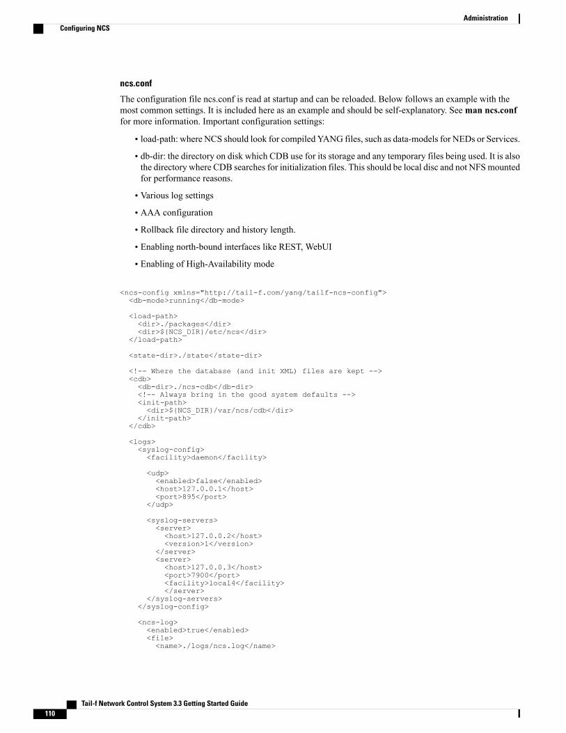
ncs.conf
The configuration file ncs.conf is read at startup and can be reloaded. Below follows an example with themost common settings. It is included here as an example and should be self-explanatory. Seeman ncs.conffor more information. Important configuration settings:
• load-path: where NCS should look for compiled YANG files, such as data-models for NEDs or Services.
• db-dir: the directory on disk which CDB use for its storage and any temporary files being used. It is alsothe directory where CDB searches for initialization files. This should be local disc and not NFSmountedfor performance reasons.
• Various log settings
• AAA configuration
• Rollback file directory and history length.
• Enabling north-bound interfaces like REST, WebUI
• Enabling of High-Availability mode
<ncs-config xmlns="http://tail-f.com/yang/tailf-ncs-config"><db-mode>running</db-mode>
<load-path><dir>./packages</dir><dir>$NCS_DIR/etc/ncs</dir>
</load-path>
<state-dir>./state</state-dir>
<!-- Where the database (and init XML) files are kept --><cdb><db-dir>./ncs-cdb</db-dir><!-- Always bring in the good system defaults --><init-path><dir>$NCS_DIR/var/ncs/cdb</dir>
</init-path></cdb>
<logs><syslog-config><facility>daemon</facility>
<udp><enabled>false</enabled><host>127.0.0.1</host><port>895</port>
</udp>
<syslog-servers><server><host>127.0.0.2</host><version>1</version>
</server><server><host>127.0.0.3</host><port>7900</port><facility>local4</facility></server>
</syslog-servers></syslog-config>
<ncs-log><enabled>true</enabled><file><name>./logs/ncs.log</name>
Tail-f Network Control System 3.3 Getting Started Guide110
AdministrationConfiguring NCS

<enabled>true</enabled></file><syslog><enabled>true</enabled>
</syslog></ncs-log>
<audit-log><enabled>true</enabled><file><name>./logs/audit.log</name><enabled>true</enabled>
</file></audit-log>
<error-log><enabled>true</enabled><filename>./logs/ncserr.log</filename>
</error-log>
</logs>
<aaa><ssh-server-key-dir>$NCS_DIR/etc/ncs/ssh</ssh-server-key-dir>
<pam><enabled>true</enabled><service>common-auth</service>
</pam>
<external-authentication><enabled>false</enabled><executable>./my-test-auth.sh</executable>
</external-authentication>
<local-authentication><enabled>true</enabled>
</local-authentication>
</aaa>
<!-- Disable this for performance critical applications, enabling --><!-- rollbacks means additional disk IO for each transaction --><rollback><enabled>true</enabled><directory>./logs</directory><history-size>5</history-size>
</rollback>
<cli><enabled>true</enabled>
<!-- Use the built-in SSH server --><ssh><enabled>true</enabled><ip>0.0.0.0</ip><port>2024</port>
</ssh>
<show-log-directory>logs</show-log-directory><show-commit-progress>true</show-commit-progress><suppress-commit-message-context>maapi</suppress-commit-message-context>
</cli>
<webui><enabled>true</enabled>
Tail-f Network Control System 3.3 Getting Started Guide 111
AdministrationConfiguring NCS

<docroot>$NCS_DIR/var/ncs/webui/docroot</docroot><transport><tcp><enabled>true</enabled><ip>0.0.0.0</ip><port>8080</port>
</tcp></transport>
<cgi><enabled>true</enabled><php><enabled>false</enabled>
</php></cgi>
</webui>
<netconf-north-bound><enabled>true</enabled>
<transport><ssh><enabled>true</enabled><ip>0.0.0.0</ip><port>2022</port>
</ssh><tcp><enabled>false</enabled><ip>127.0.0.1</ip><port>22023</port>
</tcp></transport>
</netconf-north-bound>
<rest><enabled>true</enabled></rest>
</ncs-config>
Run-time ConfigurationThere are also configuration parameters that are related to how NCS behaves when talking to the devices.These resides in devices global-settings.
admin@ncs(config)# devices global-settingsPossible completions:backlog-auto-run Auto-run the backlog at succesful connectionbacklog-enabled Backlog requests to non-responding devicescommit-queuecommit-retries Retry commits on transient errorsconnect-timeout Timeout in seconds for new connectionsned-settings Control which device capabilities NCS usesout-of-sync-commit-behaviour Specifies the behaviour of a commit operation involving adevice that is out of sync with NCS.read-timeout Timeout in seconds used when reading datareport-multiple-errors By default, when the NCS device manager commits data
southbound and when there are errors, we onlyreport the first error to the operator, this flag makes
NCS report all errors reported by manageddevices
trace Trace the southbound communication to devicestrace-dir The directory where trace files are storedwrite-timeout Timeout in seconds used when writingdata
Tail-f Network Control System 3.3 Getting Started Guide112
AdministrationRun-time Configuration

Monitoring NCSUse the command ncs --status to get runtime information on NCS.
Backup and RestoreAll parts of the NCS installation, can be backed up and restored with standard file system backup procedures.
The most convenient way to do backup and restore is to use the ncs-backup command (this only works if NCSis installed using the --system-install option). In that case the following procedure is used.
BackupNCSBackup backs up the database (CDB) files, state files, config files, and rollback files from the installationdirectory. Back up is not service affecting.
To take a complete backup (for disaster recovery), use the command:
ncs-backup
The backup will be stored in run directory /var/opt/ncs/backups/ncs-[email protected].
For more information on backup, refer to the NCS-backup man page.
RestoreNCS Restore is performed if you would like to switch back to a previous good state or restore a backup.
It is always advisable to stop NCS before performing Restore.Note
1 Stop NCS:
/etc/init.d/ncs stop
2 Backup the system:
ncs-backup --restore
Select the backup to be restored from the available list of backups. The configuration and database withrun-time state files are restored in /etc/ncs and /var/opt/ncs.
3 Start NCS:
./etc/init.d/ncs start
Tail-f Network Control System 3.3 Getting Started Guide 113
AdministrationMonitoring NCS

Tail-f Network Control System 3.3 Getting Started Guide114
AdministrationRestore