tactical commn
TRANSCRIPT
Design of ultra wide band Antenna for Tactical Communication Systems in Electronic Warfare
By
RAMASAMYRAJA R
(910012403015)
Communication systems
Anna university
Regional center- Madurai
ANNA UNIVERSITY : CHENNAI - 600 025 REGIONAL CENTER - MADURAI
MADURAI 625 002
OBJECTIVE
• Provide Tactical communication • Adverse situation
– Electronic war fare – Emergency response – Disaster relief
• using Ultra Wide Band antenna
(3.1 - 10.6 GHz band)
2


Organization of the Presentation
• ABSTRACT
• LITERATURE SURVEY
• PROPOSED METHODOLOGY • ASPECTS OF DESIGN METHODOLOGY
• RESULTS AND DISCUSSIONS
• CONCLUSION
4
ABSTRACT
• Tactical communication (military) “information of any kind, especially orders and military intelligence, are conveyed from one command, person, or place to another upon a battlefield, particularly during the conduct of combat”
• preparedness towards advert situation
Disaster relief
Emergency response
Terrorist attack
• provide tactical communication on demand – operate over wide frequency ranges – compatible with various communication standards
• more specified about design of an antenna for those kinds of applications.
5

• Proposed system : UWB antenna
• Frequency range : 3.1 GHz - 10.6 GHz
• Design : rectangular patch - corner slotted with a 2 x 2 mm
• Feeding technique : coplanar microstrip at geometric center
• Parameters : – Return loss
– VSWR
– Radiation pattern
– Impedance matching
ABSTRACT…
6
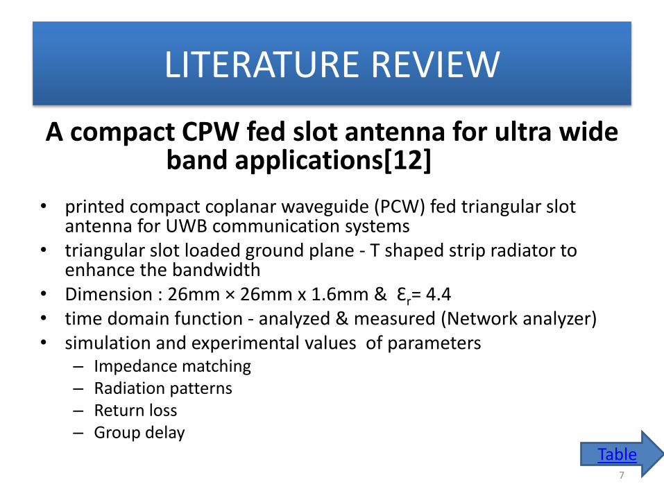
LITERATURE REVIEW
A compact CPW fed slot antenna for ultra wide band applications[12]
• printed compact coplanar waveguide (PCW) fed triangular slot
antenna for UWB communication systems • triangular slot loaded ground plane - T shaped strip radiator to
enhance the bandwidth • Dimension : 26mm × 26mm x 1.6mm & Ɛr= 4.4 • time domain function - analyzed & measured (Network analyzer) • simulation and experimental values of parameters
– Impedance matching – Radiation patterns – Return loss – Group delay
Table
7

Modeling the transient radiated and received pulses of ultra-wideband antennas[14]
• modeling for transient radiated & received pulses of UWB planar aperture
antennas
• analytically model angle-dependent pulse distortion
• relates input pulse to transient radiated fields & incident transient fields to output
pulse
• estimate - aperture field distribution from time-domain antenna measurements
• received pulses - three different antennas a ridged-horn, a dielectric loaded horn,
a Vivaldi antenna compared- measured received pulses
• comparison of pulse shape, amplitude, energy shows good agreement
• estimate -effect on transmitted pulse enabling - inclusion of pulse distortion by
antenna into UWB transceiver design
8
Table
A Multi resonant Single-Element Wideband Slot Antenna[1]
• aperture’s electric field distribution - manipulated to create two fictitious
short circuits along the slot-creating two additional resonances besides
the main one.
• frequency of fictitious resonances - chosen such that overall bandwidth
of the antenna is increased.
• Bandwidth ratio 1.8: 1
• polarization purity
• Parameter:
– impedance matching
– radiation pattern
9
Table

Ultra-Wideband Antenna Array Design for Target Detection[6]
• a four element microstrip antenna array Wilkinson
power dividers- act as feed network along with Dolph-
Chebyshev distribution and four identical patch
antenna elements.
• compact size and constant gain
• Measurement : peak gain of more than 12 dBi with
side-lobe level of 15 dB at 6 GHz.
• UWB directional antenna 10
Table
A Novel Compact CPW- Fed Antenna for Ultra Wideband Applications[5]
• consists of ground plane, rectangular slot and
polyhedron-shaped exciting stub.
• Dimension: 24mmx19mmx1.6mm and Ɛr= 4.4
• Parameters: 2D radiation patterns, VSWR, return loss,
gain and bandwidth.
• Simulation tool : Method of Moment (MOM) from
ZELAND IE3D software.
11
Table
System Design Considerations for Ultra Wide band Communication [15]
• modular platform -developing system specifications &
prototyping designs.
• modulates data with binary phase shift keyed pulses,
communicates over a wireless link using UWB antennas &
wideband direct conversion front-end & samples the received
signal for demodulation.
• Chip set operation band : 3.1–10.6 GHz
• chipset - designed using the results from the discrete
prototype.
12
Table
Countering jamming attacks against an authentication and key agreement protocol for mobile satellite communications[7]
• satellite communication systems - vulnerable to unintentional interferences &
jamming attack
• application layer security protocols cannot defend DoS attacks
• attacker jams continuously, effective security protocols ensure that
communication can continue after such interference has stopped.
• susceptible to a new DoS attack, where attackers jam a single message to
achieve a permanent DoS condition.
• additionally addresses the scenario where messages send over the mobile
satellite channel may not reach their intended recipient due to accidental or
malicious interference.
• demonstrates -effective in countering the disruptive effects of jamming.
13
Table
Resistivity Tapered Wideband High Frequency Antennas for Tactical Communications[11]
• high frequency monopole antennas - ground terminals & transmission-line
type antennas for helicopters
• tapered resistivity loading has been used to achieve a traveling wave current
distribution on the antenna.
• tapered resistivity frequency independence input impedance and radiation
pattern ,but low efficiency and comprised wideband requirements.
• spread spectrum communication systems operate at low transmitter powers,
the reduced antenna efficiency not a serious problem
• Various optimized resistivity taper profiles - allows best tradeoff between
efficiency & bandwidth
14
Table

Recent Advances In Ultra Wideband communications Systems[3]
• UWB communications for multi-user networking applications.
• 3 developments - Ad Hoc UWB communications network for tactical
voice and high-speed data communications long range UWB system
for over the water
• non line of sight voice & data
• video communications;
• wireless UWB communications network for support of both tactical
and strategic (long haul) communications.
15
Table

Millimeter-Wave Soldier-to- Soldier Communications for Covert Battlefield Operations[10]
• MANET of dismounted combat personnel which is expected to play an
important role in the future of network-centric operations.
• High speed, short range, soldier-to-soldier wireless communications - required
to relay information on situational awareness, tactical instructions & covert
surveillance data during mission.
• covert communications between soldiers - require the development of a
bespoke directive medium access layer.
• simulating dynamic soldier-to-soldier signal propagation using state of the art
animation based technology developed for computer game design
16
Table
Broadband Tactical Antenna Design[13]
• family of Broadband antennas (HF-VHF-UHF) for installation on combat cars (SUV
Hummer model)
• Discone type provide the lowest profile with minimal gain of -3 dBi in omnidirectional
azimuth coverage & ±20°elevation coverage.
• The envelope of the antenna parameters requires broadband frequency
omnidirectional coverage & high power handling capability.
• minimal size & low visibility
• develop broadband radiator 25-1000 MHz-omnidirectional beam in azimuth and ±20°
in elevation-minimal gain of -3 dBi
• Mixed polarization : vertical , some horizontal component.
• maximal height of antenna - mounted -roof of vehicle < 1.4 m
17
Table
Field test results and use scenarios for a WiMAX based Finnish broadband tactical backbone network[9]
• field test results of applying the WiMAX (IEEE 802.16e) technology for wireless tactical backbone
networks within the Finnish Defence Forces (FDF).
• FDF wireless reference architecture, new cost effective technical solutions were needed especially
for wireless tactical backbone networks.
• commercial WiMAX technology- modified for military purposes
• a set of SDR based prototype systems for testing purposes - based on commercial WiMAX
technology, adapted to NATO UHF band of 225 – 400 MHz
• FDF for wireless tactical backbone networks
• field test configuration resembled real life tactical conditions: antenna height < 2.5 meters, Omni
directional antennas, moving nodes
• field tests - fulfilled (eg) range under NLOS < 19 km.
18
Table

CPW fed Wide-Band Printed Omnidirectional Antenna[4]
• small wideband CPW fed monopole antenna for SDR mobile
communication system
• Frequency range : 800 MHz to 3000 MHz
• S11 < -10 dB
• omnidirectional radiation pattern
• Various tactical SDR communication services band
• commercial bands GSM, IMT-2000, UMTS, WiBro, WLAN
19
Table
A Novel Modified Archimedean Polygonal Spiral Antenna[10]
• Frequency range : 2–18 GHz
• modified Archimedean polygonal spiral antenna – circular spiral -highest frequencies
– square spiral antenna - lowest frequencies
• high axial ratio - UWB rectangular spiral antenna
• low profile, cavity backed polygonal model
• < 3 dB axial ratio over 97.5% of its operational bandwidth.
20
Table
Hybrid UHF/UWB Antenna for Passive Indoor Identification and Localization Systems[2]
• identification & centimeter resolution localization of multiple targets in indoor
environment
• hybrid passive UHF/UWB RFID concept - high resolution UWB impulse radio with UHF RFID identification systems
• antenna for hybrid passive tag - UHF-RFID & FCC UWB band
• co-designed UHF /UWB antenna-printed back to back -single UHF-UWB RFID chip
• Experimental tests –UHF RFID & UWB compatible
• low cost mass production of hybrid passive tags
• low cost passive RFID systems with item identification & tracking in indoor
environments
21
Table

LITERATURE REVIEW…
[12] [14] [1] [6] [5] [13] [4] [10]
Frequency
range
3.1-11.1
GHz
3.1-
10.6
GHz
3-5.4
GHz
3.6-12
GHz
1.8-15.2
GHz
25-1000
MHz
800-3000
MHz
2-18
GHz
Antenna type Printed
monopole
Vivaldi Slot Patch Patch Discone monopole Poly-
gonal
spiral
Simulation tool
used
HFSS HFSS HFSS CST IE3D CST HFSS CST
ᶓ r value 2.2,4.4,
6.15, 10.2
4.4 2.2 2.2 4.4 2.2 4.4 2.1,3.8
22

Design Methodology
23
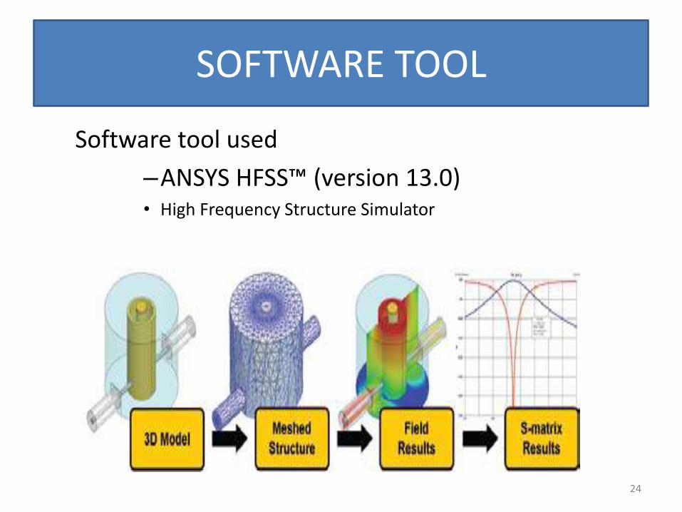
SOFTWARE TOOL
Software tool used
–ANSYS HFSS™ (version 13.0) • High Frequency Structure Simulator
24

FLOW CHART of DESIGN METHODOLOGY
25
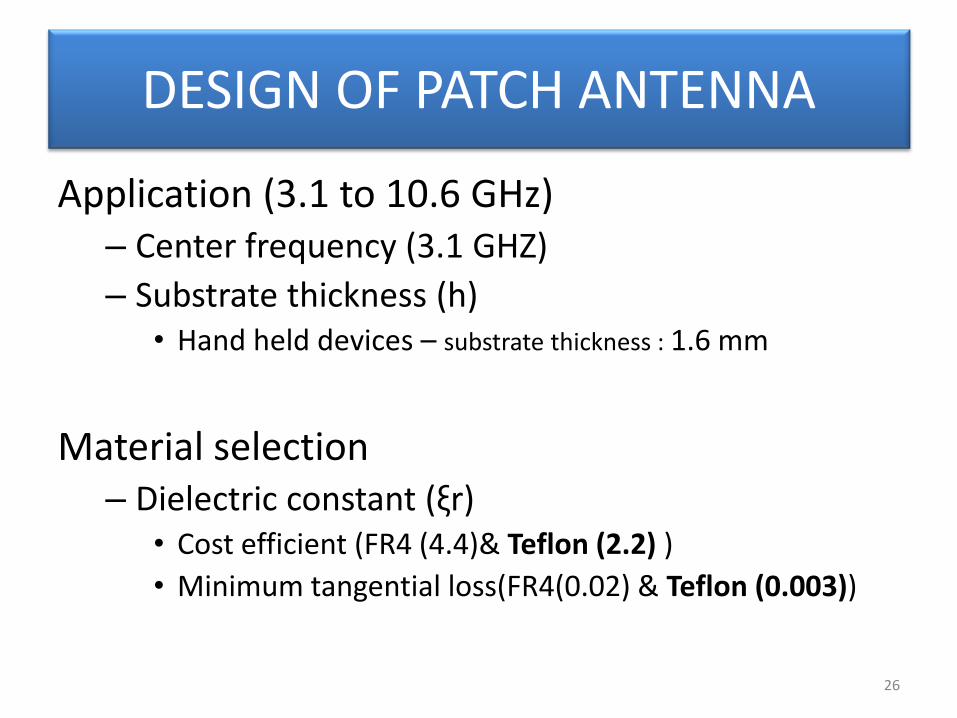
DESIGN OF PATCH ANTENNA
Application (3.1 to 10.6 GHz) – Center frequency (3.1 GHZ)
– Substrate thickness (h) • Hand held devices – substrate thickness : 1.6 mm
Material selection – Dielectric constant (ξr)
• Cost efficient (FR4 (4.4)& Teflon (2.2) )
• Minimum tangential loss(FR4(0.02) & Teflon (0.003))
26

DESIGN OF PATCH ANTENNA..
Find “W” width of patch and Effective Dielectric constant (ξreff)
W
27
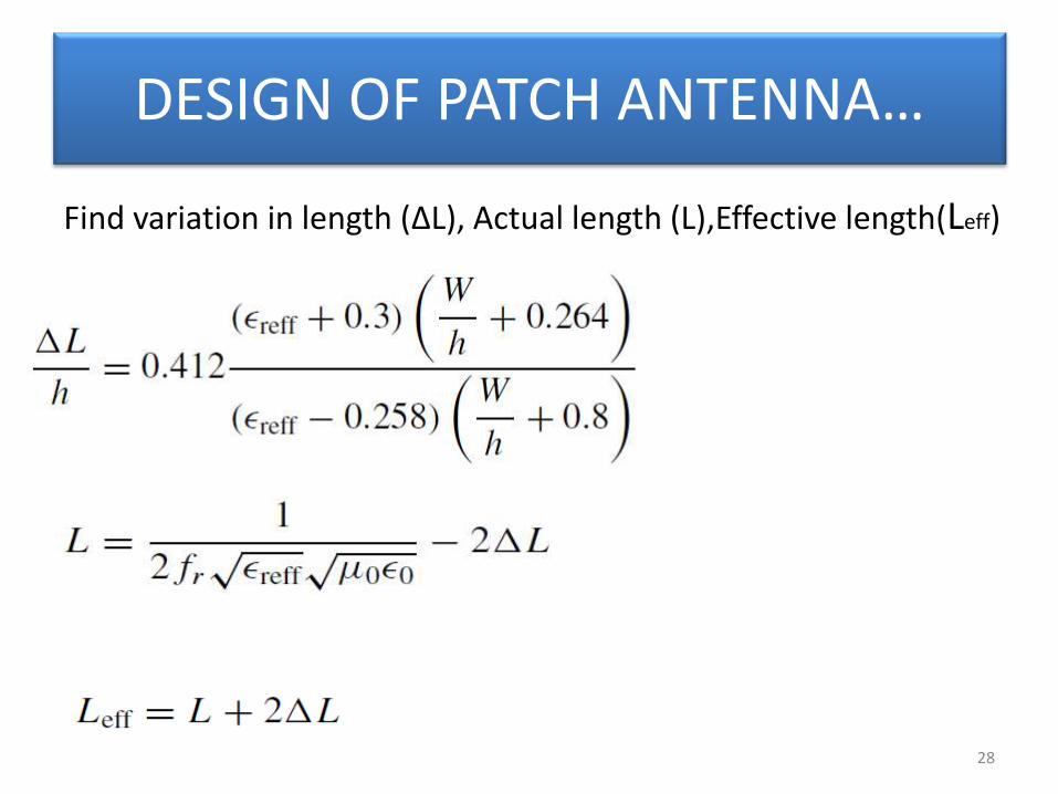
DESIGN OF PATCH ANTENNA…
Find variation in length (ΔL), Actual length (L),Effective length(Leff)
28

Design of patch antenna with matlab code
29
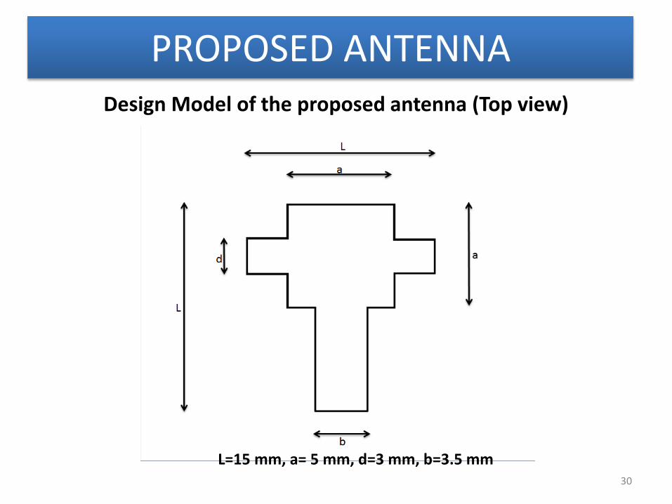
PROPOSED ANTENNA
L=15 mm, a= 5 mm, d=3 mm, b=3.5 mm
Design Model of the proposed antenna (Top view)
30

Basic Geometry of the proposed antenna of side view h=1.6mm
Design Model of the proposed antenna ( Side view)
31
RESULTS AND DISCUSSIONS
32
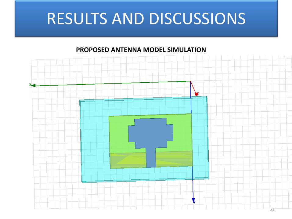
PROPOSED ANTENNA MODEL SIMULATION

Mesh convergence plot
33

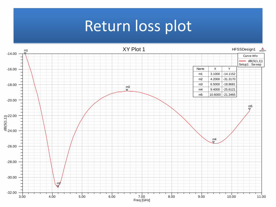
Return loss plot
3.00 4.00 5.00 6.00 7.00 8.00 9.00 10.00 11.00Freq [GHz]
-25.00
-22.50
-20.00
-17.50
-15.00
-12.50
-10.00
-7.50
-5.00
-2.50
dB
(S(1
,1))
HFSSDesign1XY Plot 1 ANSOFT
m1
m2
m3
m4
Curve Info
dB(S(1,1))Setup1 : Sw eep
Name X Y
m1 3.1000 -4.5230
m2 4.4000 -9.9762
m3 10.1000 -23.9977
m4 10.6000 -22.6619
35 3.00 4.00 5.00 6.00 7.00 8.00 9.00 10.00 11.00Freq [GHz]
-32.00
-30.00
-28.00
-26.00
-24.00
-22.00
-20.00
-18.00
-16.00
-14.00
dB
(S(1
,1))
HFSSDesign1XY Plot 1 ANSOFTm1
m2
m3
m4
m5
Curve Info
dB(S(1,1))Setup1 : Sw eep
Name X Y
m1 3.1000 -14.1152
m2 4.2000 -31.3170
m3 6.5000 -18.8681
m4 9.4000 -25.6121
m5 10.6000 -21.3465

VSWR plot
36 3.00 4.00 5.00 6.00 7.00 8.00 9.00 10.00 11.00
Freq [GHz]
1.05
1.10
1.15
1.20
1.25
1.30
1.35
1.40
1.45
1.50
VS
WR
(1)
HFSSDesign1XY Plot 2 ANSOFTm1
m2
m3
m4
m5
Curve Info
VSWR(1)Setup1 : Sw eep
Name X Y
m1 3.1000 1.4903
m2 4.2000 1.0559
m3 6.5000 1.2571
m4 9.4000 1.1106
m5 10.6000 1.1873

Radiation pattern in 2D
-4.00
2.00
8.00
14.00
90
60
30
0
-30
-60
-90
-120
-150
-180
150
120
HFSSDesign1Radiation Pattern 1 ANSOFT
Curve Info
dB(rETotal)Setup1 : LastAdaptiveFreq='5GHz' Phi='0deg'
dB(rETotal)Setup1 : LastAdaptiveFreq='5GHz' Phi='10deg'
dB(rETotal)Setup1 : LastAdaptiveFreq='5GHz' Phi='20deg'
dB(rETotal)Setup1 : LastAdaptiveFreq='5GHz' Phi='30deg'
dB(rETotal)Setup1 : LastAdaptiveFreq='5GHz' Phi='40deg'
dB(rETotal)Setup1 : LastAdaptiveFreq='5GHz' Phi='50deg'
dB(rETotal)Setup1 : LastAdaptiveFreq='5GHz' Phi='60deg'
dB(rETotal)Setup1 : LastAdaptiveFreq='5GHz' Phi='70deg'
dB(rETotal)Setup1 : LastAdaptiveFreq='5GHz' Phi='80deg'
37

Radiation pattern in 3D
38

Group Delay
3.00 4.00 5.00 6.00 7.00 8.00 9.00 10.00 11.00Freq [GHz]
0.00E+000
1.25E-010
2.50E-010
3.75E-010
5.00E-010
6.25E-010
7.50E-010
Gro
up
De
lay(1
,1)
HFSSDesign1XY Plot 1 ANSOFT
m1
m2
m3
m4
m5
m6
Curve Info
GroupDelay(1,1)Setup1 : Sw eep
Name X Y
m1 3.1000 0.0000
m2 4.1227 0.0000
m3 6.0318 0.0000
m4 8.2818 0.0000
m5 9.3727 0.0000
m6 10.6000 0.0000
39
CONCLUSION & FUTURE WORK
• Designed -antenna for tactical communication in UWB region.
• optimum performance - over UWB region
FUTURE ENHANCEMENT
• Antenna testing (chamber facility)
• MAC layer protocol for tactical communication
40

References
[1] Behdad N. and Sarabandi K. (2004) ‘A Multiresonant Single-Element Wideband Slot Antenna’, IEEE Antennas and Wireless Propag., Letters, VOL. 3. [2] Catarina C.C, Jorge R.C and Carlos A.F (2013) ‘Hybrid UHF/UWB Antenna for Passive Indoor Identification and Localization Systems’, IEEE Trans. Antennas Propag., Vol. 61, No. 1, pp. 354-361. [3] Fontuna R, Richley A.A.E, Beard L. and Guy D. (2002) ‘Recent Advances In Ultra Wideband communications Systems’, IEEE Conference on Ultra Wideband Systems and Technologies, pp. 129-134. [4] Jain A, Verma P.K, Singh V.K. and Mahakar Singh (2011) ‘CPW fed Wide-Band Printed Omnidirectional Antenna’, IEEE conference on ultra wide band Systems and Technologies, pp. 17-20. [5] kareemulla S, Manage P.S. and Gunavathi. (2013),’A Novel Compact CPW- Fed Antenna for Ultra Wideband Applications’, IOSR Journal of Electronics and Communication Engineering, Volume 4, Issue 4 ,pp 37-43.
41
References…
[6] Kasi B. and Chakrabarty C. (2012) ‘Ultra Wide band Antenna Array Design for Target Detection’, Progress in Electromagnetics Research C, Vol. 25, pp 67-79.
[7] Lasc I, Dojen R and Coffey T. (2011) ‘Countering jamming attacks against an authentication and key agreement protocol for mobile satellite communications”, journal of Computers and Electrical Engineering, vol. 37, pp.160–168.
[8] Madahar B.K, Cotton S.L. and Scanlon W.G. (2012) ‘Millimeter-Wave Soldier-to- Soldier Communications for Covert Battlefield Operations’, IEEE Communications Magazine, pp. 72-81.
[9] Mölsä J, Karsikas J, Kärkkäinen A, Kettunen R. and Huttunen P. (2010) ‘Field test results and use scenarios for a WiMAX based Finnish broadband tactical backbone network’, IEEE Military communication conference, pp. 2014-2019.
[10] Rahman N. and Mohammed N.A. (2013) ‘A Novel Modified Archimedean Polygonal Spiral Antenna’, IEEE Trans. Antennas Propag., Vol. 61, No. 1, pp. 54-61.
42
References…
[11] Rao B.R, Jones D.N and Debroux P.S. (1992) ‘Resistivity Tapered Wideband High Frequency Antennas for Tactical Communications’, IEEE Trans. Antennas Propag., pp 271-279. [12] Shameena V.A, Mridula S, Pradeep A, Jacob S, Lindo A.O. and Mohanan P. (2012) ‘A compact CPW fed slot antenna for ultra wide band applications’, Int. J. Electron. Commun.vol. 66, pp. 189–194. [13] Shokron A. and Levine E. (2010) ‘Broadband Tactical Antenna Design’, IEEE Convention of Electrical and Electronics Engineers, pp. 398-401. [14] Tan A.E, Chia M.Y, Chan K.K. and Rambabu K. (2013) ‘Modeling the transient radiated and received pulses of ultra-wideband antennas’, IEEE Trans. Antennas Propag., vol. 61, no. 1, pp. 338–345. [15] Wentzloff D.D, Blázquez R, Lee F.S, Ginsburg B.P, Powell J and Chandrakasan A.P. (2005) ‘System Design Considerations for Ultra-Wideband Communication’, IEEE Communications Magazine, pp 114-121
43