tach•pak instruction manual - aitek-usa. · pdf fileairpax instruments tach•pak®...
TRANSCRIPT

Airpax Instruments
TACH•PAK® 3Instruction Manual
This manual is applicable to all Tach•Pak 3 models.
VDO Control Systems, Inc.

Table of Contents1. Introduction...................................................................................................... 1
1.1. Overview .................................................................................................................... 11.2. Tool List ...................................................................................................................... 31.3. How to Use this Manual .......................................................................................... 31.4. Where to Go for Help ............................................................................................ 4
2 . Unpacking Instructions ............................................................................... 52.1. Package Contents ..................................................................................................... 52.2. Unpacking ................................................................................................................... 5
3 . Mounting and Wiring Procedures .......................................................... 63.1. Installation and Wiring Guidelines ......................................................................... 63.2. Mounting TACH-PAK 3 ............................................................................................ 73.3. Mounting the Speed Sensor .................................................................................... 83.4. Wiring Connections ................................................................................................. 9
3.4.1. Accessing the Terminal Blocks..................................................................... 93.4.2. Terminal Block Assignments ......................................................................... 10
3.5. Types of Speed Sensors ........................................................................................... 113.5.1. Connecting a Passive Sensor ....................................................................... 113.5.2. Connecting an Active Sensor ...................................................................... 123.5.3. Optional Circuits ........................................................................................... 123.5.4. Connecting the AC Power Supply .............................................................. 133.5.5. Connecting a DC Power Supply ................................................................. 153.5.6. Dual Power Supplies ..................................................................................... 15
4 . Control Panel / Display ............................................................................... 164.1. Scientific Notation .................................................................................................... 16
5 . Characteristics of Operation ................................................................... 175.1. The Constants ........................................................................................................... 175.2. Constant Descriptions ............................................................................................. 175.3. Meter Full Scale Frequency (FS) ............................................................................ 18
5.3.1. Display Format for Meter Full Scale Frequency ...................................... 185.3.2. Determining Meter Full Scale Input Frequency ....................................... 18
5.4. Analog Zero Scale Frequency (A0) ....................................................................... 195.4.1. Display Format for Analog Zero Scale Frequency .................................. 195.4.2. Determining Analog Zero Scale Input Frequency ................................... 19
5.5. Analog Full Scale Frequency (AF) .......................................................................... 205.5.1. Display Format for Analog Full Scale Frequency ..................................... 205.5.2. Determining Analog Full Scale Input Frequency ...................................... 20
5.6. Special Constant (SP) ............................................................................................... 225.6.1. Display Format for Special Constant (SP) ................................................ 225.6.2. Lowest Measured Frequency (time-out) ................................................... 22
5.7. Calibrate Frequency (CF) ........................................................................................ 235.7.1. Display Format for Calibrate Frequency ................................................... 23

5.8. Setpoint Classifications ............................................................................................ 245.8.1. Failsafe Setpoint .............................................................................................. 245.8.2. Non-failsafe Setpoint ..................................................................................... 24
5.9. Setpoint Categories .................................................................................................. 245.9.1. Overspeed setpoint ....................................................................................... 245.9.2. Underspeed setpoint ..................................................................................... 245.9.3. Illustrations of setpoint types ...................................................................... 25
5.10. Setpoint types ............................................................................................................ 265.10.1. Display Format for Setpoint Frequency (S1 through S4)..................... 265.10.2. EA (Energize Above setpoint) .................................................................... 265.10.3. Eb (Energize below setpoint) ..................................................................... 275.10.4. dA (de-energize Above setpoint) .............................................................. 275.10.5. db (de-energize below setpoint) ............................................................... 27
5.11. Hysteresis ................................................................................................................... 285.11.1. Display Format for Hysteresis and Type Constants (H1 – H4) ....... 285.11.2. Hysteresis bias .............................................................................................. 285.11.3. Hysteresis magnitude .................................................................................. 285.11.4. Hysteresis types ........................................................................................... 28
5.12. Frequency domain hysteresis (h) ........................................................................... 295.12.1. Example: Frequency domain hysteresis ................................................... 29
5.13. Time domain hysteresis (H) ................................................................................... 295.13.1. Example: Time domain hysteresis ............................................................. 30
5.14. Delayed Trip or Latching Relay (L) ....................................................................... 305.14.1. Delayed Trip ................................................................................................... 305.14.2. Latching relay ................................................................................................ 315.14.3. Example: Delayed Trip.................................................................................. 315.14.4. Example: Latching Relay .............................................................................. 31
6 . Adjustment Features ................................................................................... 326.1. Entering the Constants ............................................................................................ 326.2 Analog Outputs ......................................................................................................... 33
6.2.1 R1 - Meter Output Full Scale Adjusting Potentiometer ........................ 336.2.2 R2 - Analog Full Scale Adjusting Potentiometer ...................................... 34
6.3 Filter Switches ........................................................................................................... 346.3.1 SW3-1 Meter Output Filter Dip Switch ................................................... 346.3.2 SW3-2 Analog Output Filter Dip Switch .................................................. 34
7 . Reference ........................................................................................................... 35
7.1. Specifications .............................................................................................................. 357.1.1. Power Supply .................................................................................................. 357.1.2. Signal Input ...................................................................................................... 357.1.3. Outputs ............................................................................................................ 357.1.4. Environmental ................................................................................................. 36
7.2. Glossary ...................................................................................................................... 377.3. Target Variable Conversions ................................................................................... 39
Warranty..................................................................................................................... 40Index ............................................................................................................................ 41Recorded Stored Constants ................................................................................... 43

1
I. Introduction
TACH-PAK 3 is a single-input industrial tachometer that measures the rate of events. Usingvarious sensors, TACH-PAK 3 can measure events as simple as the speed of a rotating shaft,the rate at which paper passes through a press, or as diverse as the rate at which liquid flowsthrough a pump.
1 . 1 OverviewA speed sensor placed near a target, such as a rotating gear, generates a repeating electricalpulse. The rate of repetition is proportional to the rate of the event you want to measureand represents the input frequency. TACH-PAK 3 measures this rate in number of pulses persecond (hertz). This input signal from the sensor is conditioned, analyzed by a microcom-puter and routed to the outputs.
TACH-PAK 3’s microcomputer uses a scheme of data acquisition called adaptive periodaveraging, a unique frequency measuring method in which the number of periods averagedchanges with the frequency to obtain optimal accuracy. At input frequencies of 100 Hz andabove, the outputs are updated every 30 milliseconds.
TACH-PAK 3 provides three scaleable output types:
• 0-1 mA DC meter output
• 0-20/4-20 mA DC analog output
• Four Form C (SPDT) relay setpoints
To set up TACH-PAK 3, first determine how each output should behave in your application,then enter the setup information as thirteen “constants” through TACH-PAK 3’s internalcontrol panel. (See Section 4.) The constants are stored in TACH-PAK 3’s electricallyalterable read-only memory (EAROM). They can be viewed and altered individually in muchthe same way you set a digital watch.

2
Figure 1. Operation Flow Diagram
To put TACH-PAK 3 into operation, complete the following steps:
1. Mount TACH-PAK 3 See Section 3.2
2. Install and connect the appropriate output wiring. See Section 3.4.1
3. Install and connect the speed sensor See Sections 3.5.1 and 3.5.2
4. Install and connect the power wiring See Section 3.5.4 or 3.5.5
5. Enter the constants into TACH-PAK 3 See Section 6
This manual describes all five steps.
Note: By connecting temporary power wiring, TACH-PAK 3 can bepowered up and programmed prior to mounting it on the application.
NOTE

3
1.2 Tool List
You will need the following tools to perform the procedures described in this manual:
#1 or #2 Phillips screwdriver
#4 Phillips screwdriver
#2 straight blade screwdriver
1.3 How to Use this Manual
This manual contains the following sections:
Chapter 1 - Introduction contains a brief description of TACH-PAK 3.
Chapter 2 - Unpacking Instructions describes the package contents and proper removal ofTACH-PAK 3.
Chapter 3 - Mounting and Wiring Procedures contains instructions for mounting the speedsensor and making the electrical connections.
Chapter 4 - Control Panel/Display describes the internal control panel and display, scientificnotation, the constants, the function of each constant, and how to determine its appropriatevalue. Examples are provided.
Chapter 5 - Characteristics of Operation describes setpoints, hysteresis and how they areused by the constants to control the four relays.
Chapter 6 - Entering the Constants gives procedures for how to enter and store the con-stants.
Chapter 7 - Reference contains specifications, a glossary, and other technical information.
The Appendices contain an index and other customer information.

4
This manual uses the following conventions:
Note: provides an explanation or amplification.
Caution: advises you risk damaging your equipment if you do not heedinstructions.
Danger: advises you risk danger to personal health if you do not followinstructions carefully.
1.4 Where to Go for Help
For technical support and programming assistance onthis product, please contact your local distributor. To locate
the distributor closest to you, please call:
1-800-643-0643
NOTE
CAUTION
DANGER

5
2. Unpacking InstructionsTo ensure safe transit every TACH-PAK 3 is thoroughly tested and carefully packed beforeleaving the plant. Responsibility for its safe delivery was assumed by the carrier upon accep-tance of the shipment. Claims for loss or damage sustained in transit must be made to thecarrier.
2.1 Package ContentsTACH-PAK 3 is shipped in a single carton that contains:
• one TACH-PAK 3
• one instruction manual
Note: Electrical and mounting hardware are not supplied.
2.2 Unpacking
CAUTION: TACH-PAK 3 is a precision instrument. Although it is designed towithstand the rigors of industrial use, excessive physical shock or vibration candamage it. Handle it carefully. Do not drop or subject it to physical extremesexceeding those specified in Section 7.1.4.
1. Place the carton on a level surface in a well-lighted area and open the top.
2. Carefully lift out TACH-PAK 3 and the packing material.
3. Remove the packing material.
4. Remove the instruction manual from the carton.
5. Inspect your TACH-PAK 3 for concealed damage.
NOTE
CAUTION

6
3. Mounting and Wiring Procedures
3.1 Installation and Wiring GuidelinesAdhere to these guidelines when installing your instrument:
1. Locate TACH-PAK 3 away from sources of water, humidity, heat, and dust; or provide asuitable enclosure to protect it from these elements.
2. Locate TACH-PAK 3 away from sources of electrical noise such as, but not limited to:SCRs, triacs, buzzers, horns, motors, welding equipment, contactors, heavy current relays,and other electrical noise generating equipment.
3. Use a metal enclosure to protect TACH-PAK 3 from radiated electrical noise or othermagnetic influences. If TACH-PAK 3 is removed from its original enclosure, it should beinstalled only in panels or cabinets with other low level electronic devices.
4. Separate low voltage signal and control wiring from switching and power wiring. Plancabinet and panel wiring so that the power and relay wiring are dressed to one side andlow level signals dressed to the other side. Plan wiring to maintain separation at entry toand egress from the enclosure.
5. Signal and control wiring should be at a minimum run in twisted pairs. Lines for magneticpick-ups, pulse type outputs and other frequency devices should be run in separateshielded cables.
6. Try not to use commutators or slip rings to transmit low level signals. Should this beabsolutely necessary, ensure that the point of contact is maintained and clean at all times.Refer questions about this type of application to your local distributor.
7. Connect the shields of shielded cables so that no current flows in the shield by firstconnecting all of the shields in series then to the shield terminal on TB2-9. Do notground the shield at any point other than the instrument (if it’s equipped with a non-metallic enclosure). If equipped with a metal enclosure, connect the enclosure to anearth ground.
8. Provide a power line that is free of noise and power interruption. Normally this will be abus for use by low power electronic devices. In some cases this may require constantvoltage, isolation, or noise filters.
9. DC power supplies sourcing the tachometer should operate within the limits provided inthe instrument’s specifications. Applications involving battery chargers should be avoidedunless isolation can be provided between the charger system and TACH-PAK 3.

7
3.2 Mounting TACH-PAK 3Locate the TACH-PAK 3 enclosure to allow for proper clearances as shown in the figurebelow.
Drill four holes in the panel on which the TACH-PAK 3 is to be mounted using the figure foryour model of TACH-PAK 3 below as a guide.
Figure 2. TACH-PAK 3 Dimensions and mounting hole pattern
NEMA-1
NEMA-7, -9
NEMA-4X

8
3.3 Mounting the Speed SensorThe sensor should be secured in a rigid mount. Normal machine vibration should not affectthe accuracy of the display reading. However, relative motion between the sensor and thetarget can introduce false pulses and lead to incorrect readings.
Complete the following steps to mount the sensor:
1. Place the speed sensor into the mounting. Do not secure it at this time.
2. If it is an active sensor, proper orientation is required. The orientation flat or notch onthe housing must be parallel with the gear teeth or target irregularity.
3. When using an Airpax speed sensor, use a feeler gauge to set the clearance between thesensor and the gear according to the sensor specifications.
Figure 4. Setting Gap with Feeler Gauge
4. Lock the sensor securely in position with the jamb nut(s).
CAUTION: Do not overtighten the jamb nut(s).
5. Rotate the target one complete turn to ensure that the target never contacts the sensor.
CAUTION: At no time in its revolution should the target touch the sensor ordamage to the sensor will occur.
CAUTION
Figure 3. Active Sensor Mounting
Orientation Flat Notch
CAUTION

9
3.4 Wiring ConnectionsElectrical connections are made to two terminal blocks inside the TACH-PAK 3 — terminalblock 1 (TB1) and terminal block 2 (TB2). TB1 is used for AC power connections and outputrelay wiring. TB2 is used for DC power and sensor connections, current loop outputs, andreset and calibrate functions.
Figure 5. AC Wiring Connection
3.4.1 Accessing the Terminal Blocks1. To access terminal block 2 (TB2), use a No. 1 or No. 2 Phillips head screw driver to
remove the three screws on the top of the primary cover and lift it off.
DANGER: Before removing the subcover over the power supply, make sureTACH-PAK 3 is not connected to a voltage source. Line voltages are accessiblewhen the subcover is removed.
2. To access terminal block 1 (TB1), remove the two screws on the top of the protectivesubcover over the power supply area and lift it off.
DANGER
Figure 6. Terminal Blocks
TB1TB2

10
Terminal Use Terminal Use
CAUTION
NOTE
3.4.2 The terminal block assignments are shown below.
Terminal Block Assignments
Terminal Block 2 (TB2) Terminal Block 1 (TB1)
1 +24 VDC In 1 K1 N.C.
2 DC Common (power in) 2 K1 Com.
3 Calibrate/Verify 3 K1 N.O.
4 DC Common (power out) 4 K2 N.C.
5 +12 VDC Out 5 K2 Com
6 Relay reset 6 K2 N.O
7 Signal + 7 K3 N.C.
8 Signal - 8 K3 Com
9 Shield 9 K3 N.O.
10 Meter + (0-1 mA) 10 K4 N.C.
11 DC Common (analog & meter) 11 K4 Com
12 Analog +(0-20 / 4-20 mA) 12 K4 N.O.
13 AC Power Hot
14 AC Power Neutral
15 Earth
NOTE: Relays shown in de-energized state.
CAUTION: Signal leads between the sensor and TACH-PAK 3 should beshielded twisted pair with insulation over the shielding. This will provideeffective noise shielding and is recommended for all sensor, analog output,and meter output cables. Nevertheless, do not run signal leads near noisesources such as switches and power lines that carry large currents.
Connect shields at the instrument end only. Trim the shield at the sensor end and insulate itto prevent any electrical contact with the conduit or other grounds.

11
3.5 Types of Speed SensorsTACH-PAK 3 is designed to operate with standard Airpax sensors. For applications usingirregular discontinuities as targets consult Airpax Product Catalog (#13000) or your localdistributor.
The type of speed sensor used with TACH-PAK 3 depends on the speed of the applicationbeing monitored. Passive (non-powered) speed sensors that produce a signal in the form ofan analog sine wave can be used with TACH-PAK 3 in most applications. Low-speed applica-tions require active (powered) zero-velocity speed sensors that produce a signal in the formof a digital square wave. You will have to tell TACH-PAK 3 what type of signal it will bereceiving as described in Sections 3.5.1 and 3.5.2.
If you are using another manufacturer’s speed sensor, follow their recommended installationprocedures.
3.5.1 Connecting a Passive SensorThese connections are for a passive sensor producing a zero-crossing analog sine wave.
Connect the sensor as shown in the diagram below.
Figure 7. Passive Sensor Connection
Note: Be sure to enter a “P” for passive in the special constant (SP) whenyou enter the constants. (See Section 5.6.1.)
NOTE

12
3.5.2 Connecting an Active SensorThese connections are for an active sensor producing a ground-referenced digital squarewave. Other active or TTL sensors should be connected the same way.
Connect the sensor as shown in the diagram below.
Figure 8. Active Sensor Connection
Note: Be sure to enter an “A” for active in the special constant (SP) when youenter the constants. (See Section 5.6.1.)
3.5.3 Optional CircuitsYou can set up optional verification and relay reset circuits at this time according to thewiring diagrams below.
Figure 9. Relay Reset
NOTE

13
Figure 10. Calibrate / Verify Connection
3.5.4 Connecting the AC Power Supply
CAUTION: Do not exceed the maximum supply voltage to TACH-PAK 3 asspecified in Section 7.1.1.
DANGER: A shock hazard exists in the power supply area when the power isapplied to the instrument. Do not touch or place objects in the power supplyarea when power is being applied to the TACH-PAK 3. If TACH-PAK 3 hasalready been connected to a power source, disconnect it before proceeding.Proper lockout procedures should be observed.
CAUTION
DANGER

14
Attach a power cord (not provided) to TB1 as follows:
1. TB1-13 AC hotTB1-14 AC neutralTB1-15 earth
2. Replace the protective subcover over the power supply area to reduce shock hazard. Youwill not need to remove this cover again to program TACH-PAK 3, only to connect therelay wiring.
Figure 11. AC Power Connection

15
3.5.5 Connecting a DC Power Supply
CAUTION: Do not exceed the maximum supply voltage to TACH-PAK 3 asspecified in Section 7.1.1.
DANGER: A shock hazard exists in the power supply area when the power isapplied to the instrument. Do not touch or place objects in the power supplyarea when power is being applied to the TACH-PAK 3. If TACH-PAK 3 hasalready been connected to a power source, disconnect it before proceeding.Proper lockout procedures should be observed.
Attach a power cord (not provided) to TB2 as follows:
TB2-1 +24V dcTB2-2 DC common
3.5.6 Dual Power SuppliesFor applications that involve a backup or auxiliary power supply, you should make provisionsto switch in the alternate power supply externally from the instrument.
In special applications it is possible to connect both an AC and a DC power source simulta-neously to TACH-PAK 3. However, strict attention must be paid to the system design inorder to prevent damage to TACH-PAK 3. Please consult your local distributor for informa-tion regarding applications utilizing dual power supplies.
CAUTION
DANGER
Figure 12. DC Power Connection
16
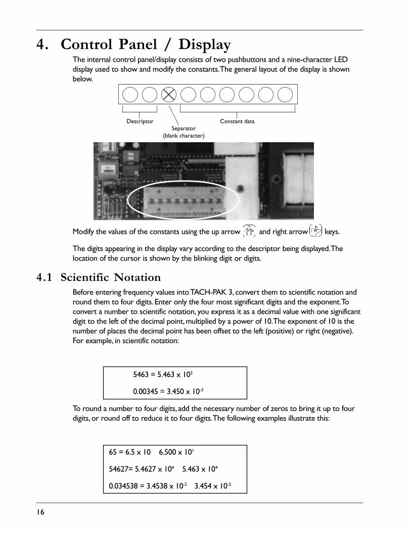
4. Control Panel / DisplayThe internal control panel/display consists of two pushbuttons and a nine-character LEDdisplay used to show and modify the constants. The general layout of the display is shownbelow.
Modify the values of the constants using the up arrow and right arrow keys.
The digits appearing in the display vary according to the descriptor being displayed. Thelocation of the cursor is shown by the blinking digit or digits.
4.1 Scientific NotationBefore entering frequency values into TACH-PAK 3, convert them to scientific notation andround them to four digits. Enter only the four most significant digits and the exponent. Toconvert a number to scientific notation, you express it as a decimal value with one significantdigit to the left of the decimal point, multiplied by a power of 10. The exponent of 10 is thenumber of places the decimal point has been offset to the left (positive) or right (negative).For example, in scientific notation:
5463 = 5.463 x 10³
0.00345 = 3.450 x 10⁻³
To round a number to four digits, add the necessary number of zeros to bring it up to fourdigits, or round off to reduce it to four digits. The following examples illustrate this:
65 = 6.5 x 10 6.500 x 101
54627= 5.4627 x 10⁴ 5.463 x 10⁴
0.034538 = 3.4538 x 10⁻² 3.454 x 10⁻²
Separator(blank character)
Constant dataDescriptor

17
5.0 Characteristics of Operation
5.1 The ConstantsThe constants and their descriptors are listed below in the order they appear in the display, withstandard constant as set at the factory.
Constant Descriptor Std. Constant
Meter Full Scale Frequency
Analog Zero Scale Frequency
Analog Full Scale Frequency
Calibrate Frequency (verify)
Setpoint 1 Frequency
Setpoint 1 Hysteresis and Type
Setpoint 2 Frequency
Setpoint 2 Hysteresis and Type
Setpoint 3 Frequency
Setpoint 3 Hysteresis and Type
Setpoint 4 Frequency
Setpoint 4 Hysteresis and Type
Special
5.2 Constant DescriptionsTo control the operation of TACH-PAK 3, you will determine, enter, and store values for 12operational constants and one calibration constant in memory
This chapter describes each of the constants in detail and gives procedures and examples fordetermining the value of each constant. Section 6 describes how to enter and store theconstants in TACH-PAK 3.
Note: Values for the constants are entered in scientific notation. If you areunfamiliar with scientific notation, see Section 4.1 for directions.
NOTE
F S
A 0
A F
C F
S 1
H 1
S 2
H 2
S 3
H 3
S 4
H 4
S P
3 0 0 0 4
0 0 0 0 0
3 0 0 0 4
3 0 0 0 4
5 0 0 0 3
E A h 1 00
1 0 0 0 4
E A h 1 00
2 0 0 0 4
E A h 1 00
3 0 0 0 4
E A h 1 00
0 P 01

18
5.3 Meter Full Scale Frequency (FS)5.3.1 Display Format for Meter Full Scale Frequency
X denotes a blank character.
5.3.2 Determining Meter Full Scale Input FrequencyTACH-PAK 3 provides a 0-1 milliampere proportional current output that can be used todrive an analog meter or an auxiliary device. This output is referred to as the meter output.
The meter output zero scale value is always zero Hz. You must determine the input fre-quency at which the meter output delivers 1.0 mA (the meter full scale). To calculate the fullscale frequency, you need to know:
1. The number of pulses per revolution from the target (PPR)
2. The revolutions per minute (RPM) at which you want the meter output to deliver 1.0mA
Use the following equation to determine the input signal frequency to generate 1.0 mA:
Convert the frequency to scientific notation, round it to four digits and record this value onthe setup sheet.
Sample application. You are using a TACH-PAK 3 to monitor the speed of a gear with 54teeth. At the desired full scale speed, the gear is turning at 3025 rpm. The formula is:
(REV/MIN) x (PULSES/REV)(SEC/MIN)
RPM x PPR60= FREQUENCY=
RPM x PPR60=FREQUENCY = 3025 x 54
60 = 2722.5 Hz
F S
Descriptor Mantissa
ExponentSign

19
Convert to scientific notation:
2722.5 Hz = 2.7225 x 10³ Hz
Round to four significant digits and record on the setup sheet:
2.7225 x 10³ Hz 2.723 x 10³ Hz
Note: If you are measuring rpm from a 60-tooth gear, then frequency willequal rpm. In the above example, if the gear wheel had 60 teeth, the formulawould be:
5.4 Analog Zero Scale Frequency (A0)5.4.1 Display Format for Analog Zero Scale Frequency
X denotes a blank character.
5.4.2 Determining Analog Zero Scale Input FrequencyThe analog output from TACH-PAK 3 is a proportional current source of either 0 to 20 mAor 4 to 20 mA that can be used to drive industrial devices such as recorders, meters,controllers and instruments operated by a current loop. You must determine the frequencyat which the analog output delivers the minimum (zero scale) and maximum (20 mA) cur-rent.
Note: Values for the constants are entered in scientific notation. If you areunfamiliar with scientific notation, see Section 4.1 for directions.
To determine the analog output zero scale frequency, use the frequency formula below todetermine the frequency at which the analog output will deliver the zero scale current value.
3025 x 6060 = 3025 Hz = 3.025 x 10³NOTE
A 0
Descriptor Mantissa
ExponentSign
NOTE
RPM x PPR60=FREQUENCY

20
Record this value on the setup sheet and enter it in the Analog Zero Scale Frequency Con-stant (A0). Section 6 describes how to enter constants.
To specify the zero scale current value, enter either 0 or 4 in the Special Constant (SP). (SeeSection 5.6.1.)
Sample application. You are using a TACH-PAK 3 to sense the speed of a gear with 48 teeth.At the desired analog zero scale frequency, the gear is turning at 500 rpm. The formula is:
Convert to scientific notation, round to four digits, and record on the setup sheet:
400 Hz = 4.000 x 10²
5.5 Analog Full Scale Frequency (AF)5.5.1 Display Format for Analog Full Scale Frequency
X denotes a blank character.
5.5.2 Determining Analog Full Scale Input FrequencyUse the frequency formula below to determine the frequency at which the analog output willdeliver 20 mA.
Convert the result to scientific notation and record it on the setup sheet.
RPM x PPR60=FREQUENCY = 500 x 48
60 = 400 Hz
A F
Descriptor Mantissa
ExponentSign
RPM x PPR60=FREQUENCY

21
Note: You can invert the scale by making the zero scale value larger than thefull scale value.
Note: The 0-20 mA can be converted into a 0-5 VDC or 0-10 VDC signal byplacing a scaling resistor across the input of the receiving instrument. Theparallel combination of the scaling resistor and the input resistance of theinstrument must equal 250 ohms for 0-5 VDC or 500 ohms for 0-10 VDC.
Sample application. You are monitoring a 60 Hz power line and want to use the analog outputto drive a recorder that will record fluctuations in the frequency of the power line. Your areaof concern is the frequency around 60 Hz.
If you set the analog zero scale at 1 Hz and the full scale at 60 Hz, the span of the scale (thedifference between the full scale value and the zero scale value) would be so small thatfluctuations around 60 Hz would be difficult to observe. To create an expanded scale thatmagnifies the portion of the frequency scale you are concerned with, you might set theAnalog Zero Scale Frequency (A0) to 57 Hz, and the Analog Full Scale Frequency (AF) to 63Hz.
Note: The span of the analog output (the difference between AF and AO)should not be expanded beyond .05 ( ) of the full scale value (AF). Tocheck this relationship, use the following formula:
In the power line example, the full scale value is 63 Hz, so the span of theexpanded analog scale must be greater than or equal to 3.15 Hz (63 x .05).The expanded scale in the example is 6 Hz wide, which is acceptable.However, a 59 Hz zero scale value and a 61 Hz full scale value produce aspan of only 2 Hz, which would be unacceptable.
Since the power line frequencies in this example are already in Hz, you simply convert themto scientific notation, round to four digits, and record them:
• Analog zero scale frequency = 5.700 x 101
• Analog full scale frequency = 6.300 x 101
Note: With expanded scales, the greater the magnification of the scale, thegreater the magnification of mechanical irregularities such as machine jitter.
NOTE
NOTE
NOTE
NOTE
120
AF – AOAF
> .05

22
5.6 Special Constant (SP)5.6.1 Display Format for Special Constant (SP)
The special constant is used to set the following parameters:
• The zero scale value expressed in milliamperes delivered by the analog output (either 0mA or 4 mA). See Section 5.4.2.
• The input type (passive or active). See Sections 3.5.1 and 3.5.2.
• The lowest measured frequency (time-out period) See Section 5.6.2.
5.6.2 Lowest Measured Frequency (time-out)This parameter sets the amount of time required to recognize that the process is stopped.You must choose one of the eight periods listed in the table below and enter the corre-sponding time-out period in the special constant. (See Section 6.) This is the amount of timeTACH-PAK 3 will wait to end the data acquisition.
Note: You should not pick a time out period that is lower than is required bythe application, because this period is the amount of time required to indicatezero speed.
10.0000 Hz 0.15.0000 Hz 0.22.0000 Hz 0.51.0000 Hz 1.0.5000 Hz 2.0.2500 Hz 4.0.1250 Hz 8.0.0625 Hz 16
S P
Descriptor
Analog Output0 = 0 – 20 mA4 = 4 – 20 mA
Input Type“P” – Passive
“A” – Active (TTL)For active sensor types add ajumper from TB2-8 to TB2-4
Time OutPeriod (seconds)
0.10.20.51.02.04.08.016
NOTETime-out
PeriodLowest Frequency
Measured

23
Note: Generally the relationship between the highest frequency measuredand the lowest should be about 1000 to 1. If the highest frequency you aremeasuring is 5000, then you might choose 5 as the lowest measured fre-quency and enter 0.2 in the special constant. However, an appropriate time-out is entirely application dependent. Refer questions to your local distributor.
5.7 Calibrate Frequency (CF)5.7.1 Display Format for Calibrate Frequency
X denotes a blank character.
This constant is used to verify the operation of the instrument and the behavior of theoutputs. When 12 VDC is applied to the verify input, TACH-PAK 3 behaves as if the valueentered in CF were the input frequency.
Use CF to:
1. Test the setpoints by making the verify value slightly larger than the setpoint and seeing ifthe relay trips.
2. Calibrate the outputs of both the meter and analog functions.
3. Test devices connected to the analog output such as a meter, chart recorder, or alarm.
CAUTION: When CF is active, the CF value overrides the input frequency forthe duration of the applied CF signal. During this time, TACH-PAK 3 is notmonitoring the process.
NOTE
C F
Descriptor Mantissa
ExponentSign
CAUTION

24
5.8 Setpoint ClassificationsThe TACH-PAK 3 has four relay setpoints (S1, S2, S3, and S4). A setpoint is a value of inputfrequency that causes a relay to change state (energize or de-energize). A setpoint value isexpressed in Hertz (number of cycles per second). There are several different types of relaybehavior available, and they are divided into two major classifications, Failsafe and Non-failsafe.
5.8.1 Failsafe SetpointFailsafe refers to a mode of operation where loss of power to TACH-PAK 3 will result in analarm condition at the relay contacts. Alarm condition is defined as the relay state that signalsa fault to auxiliary or support equipment. This type of relay behavior should be used inapplications where loss of speed control cannot be tolerated or will result in a hazardouscondition to personnel or monitored equipment.
5.8.2 Non-failsafe SetpointNon-failsafe refers to a mode of operation where loss of power to TACH-PAK 3 will notresult in an alarm condition at the relay contacts. Alarm condition is defined as the relaystate that signals a fault to auxiliary or support equipment. This type of relay behavior shouldonly be used in applications where loss of speed control will not result in a hazardouscondition to personnel or monitored equipment.
5.9 Setpoint CategoriesBoth failsafe and non-failsafe setpoints have two categories of setpoint operation, overspeedand underspeed.
5.9.1 Overspeed setpointOverspeed setpoints are used where control of a condition involving excess speed is re-quired.
5.9.2 Underspeed setpoint Underspeed setpoints are used where control of a condition involving too low a speed isrequired.

25
5.9.3 Illustrations of setpoint types
Figure 13. Setpoint Types
EA
Eb
dA
db
OVERSPEED, NON-FAILSAFE
UNDERSPEED, NON-FAILSAFE
OVERSPEED,FAILSAFE
UNDERSPEED,FAILSAFE

26
5.10 Setpoint types
TACH-PAK 3 has four setpoint types available to each relay using the terms previouslydefined. They are described in the following paragraphs.
5.10.1 Display Format for Setpoint Frequency (S1 through S4)X denotes a blank character.
5.10.2 EA (Energize Above setpoint)This setpoint type should be used in applications where non-failsafe control of an overspeedcondition is desired. Operation of this type is as follows (Refer to the setpoint illustrations inSection 5.9.3.):
• If the monitored application is operating at a speed below the setpoint, the relay is de-energized.
• If speed increases beyond the setpoint value, the setpoint enters the alarm condition andenergizes the relay.
• The relay will remain energized until the speed decreases to a value below the resetpoint of the hysteresis band at which point the relay is de-energized.
The reset point of a relay is determined by the hysteresis type and magnitude as configuredin the hysteresis constant for that relay. For information on hysteresis refer to Section 5.11.
S 1
Descriptor Mantissa
ExponentSign

27
5.10.3 Eb (Energize below setpoint)This setpoint type should be used in applications where non-failsafe control of anunderspeed condition is desired. Operation of this type is as follows (Refer to setpointillustrations in Section 5.9.3.):
• If operating at a speed above the setpoint, the relay is de-energized.
• If speed decreases below the setpoint value, the setpoint enters the alarm condition andenergizes the relay.
• The relay will remain energized until the speed increases to a value above the reset pointof the hysteresis band at which point the relay is de-energized.
The reset point of a relay is determined by the hysteresis type and magnitude as configuredin the hysteresis constant for that relay. For information on hysteresis refer to Section 5.11.
5.10.4 dA (de-energize Above setpoint)This setpoint type should be used in applications where failsafe control of an overspeedcondition is desired. Operation of this type is as follows (Refer to setpoint illustrations inSection 5.9.3.):
• If operating at a speed below the setpoint, the relay is energized.
• If speed increases beyond the setpoint value, the setpoint enters the alarm condition andde-energizes the relay.
• The relay will remain de-energized until the speed decreases to a value below the resetpoint of the hysteresis band at which point the relay is energized.
The reset point of a relay is determined by the hysteresis type and magnitude as configuredin the hysteresis constant for that relay. For information on hysteresis refer to Section 5.11.
5.10.5 db (de-energize below setpoint)This setpoint type should be used in applications where failsafe control of an underspeedcondition is desired. Operation of this type is as follows (Refer to setpoint illustrations inSection 5.9.3.):
• If operating at a speed above the setpoint, the relay is energized.
• If speed decreases below the setpoint value, the setpoint enters the alarm condition andde-energizes the relay.
• The relay will remain de-energized until the speed increases to a value above the resetpoint of the hysteresis band at which point the relay is energized.
The reset point of a relay is determined by the hysteresis type and magnitude as configuredin the hysteresis constant for that relay. For information on hysteresis refer to Section 5.11.

28
5.11 HysteresisThe function of hysteresis in setpoint relays is to provide a dead band that will preventpremature release of a relay in the alarm condition. Airpax tachometers provide a great dealof flexibility in the configuration of hysteresis behaviors or types. With each hysteresis type,the magnitude of the hystersis band, as well as the events necessary to permit the release ofa tripped setpoint, can be defined. Each setpoint has associated with it a hysteresis constant(H1, H2, H3, and H4). It is the configuration of this constant that determines the hysteresisbehavior of each setpoint.
The hysteresis constant must be set to control the behavior of each relay setpoint beingused in your application. Each hysteresis constant contains information that determines threecharacteristics of operation for each relay: bias, type and magnitude.
5.11.1 Display Format for Hysteresis and Type Constants (H1 through H4)
5.11.2 Hysteresis biasThe most important property of hysteresis is its bias relative to the setpoint value. It comesinto effect either above or below the setpoint value. Overspeed setpoints have the hysteresisband located below the setpoint value to allow the setpoint to trip (alarm) at the prescribedvalue as speed increases, and to permit release of the setpoint when speed decreases to asafe level. Underspeed setpoints have the hysteresis band located above the setpoint value toallow the setpoint to trip (alarm) at the prescribed value as speed decreases, and to permitrelease of the setpoint when the speed increases to a safe level. Refer to the illustrations infigure 5.9.3.
5.11.3 Hysteresis magnitudeMagnitude defines the size of the dead band. The means used to describe it vary according tothe type of hysteresis being applied to the setpoint.
5.11.4 Hysteresis typesTACH-PAK 3 has three types of hysteresis available to each relay setpoint:
• frequency domain hysteresis• time domain hysteresis• latching relay with delay
They are described in detail on the following pages.
H 1
Descriptor
Hysteresis Magnitude in percentFor type “h” (format xx.x%) and
in number of data acquisitions fortype “H” and “L” (format 3 digits)Hysteresis Type
“h” – frequency hysteresis“H” – time hysteresis
“L” – latching
Hysteresis Bias“A” = above“b” = below
Relay Command“E” = energize
“d” = de-energize

29
5.12 Frequency domain hysteresis (h)Frequency domain hysteresis uses a percentage of the setpoint value to calculate the resetpoint of a relay in the alarm condition.
5.12.1 Example: Frequency domain hysteresisA setpoint is programmed as follows:
• setpoint configuration: EA (energize above setpoint)
• setpoint value: 1000 Hz
• hysteresis type: h
• hysteresis value: 10.0%.
The hysteresis band would be 100 Hz wide (1000 x .100). The setpoint would energize therelay (alarm) if the speed was equal to or greater than 1000 Hz, and de-energize the relay(reset point) when the speed decreased to 900 Hz or less. This type of hysteresis is the mostcommon due to its ease of use.
5.13 Time domain hysteresis (H)Time domain hysteresis uses intervals of time (data acquisitions) in combination with theincoming frequency to calculate the reset point of a relay in the alarm condition. The magni-tude of H type hysteresis is expressed as the number of consecutive data acquisitions not inviolation of the setpoint.
To calculate the data acquisition time:
1. Choose the setpoint frequency and delay time. 20 Hz5 sec.
2. Multiply the input frequency by .03. 20 x .03 = .6If the result is not a whole number,round it to the next higher whole number. .6 1
3. Multiply the result by the reciprocal 1 x = .05of the input frequency.
4. The result represents the time .05 secondsof one data acquisition.
5. Number of data acquisitions is the delay time 5 / .05 = 100(sec.) divided by one data acquisition time (sec.).
6. Time delay is specified as 0 to 999data acquisitions.
Example
You enter 100 as thehysteresis value portionof the constant.
201

30
Note: If the input frequency is not steady, the data acquisition time will varyin proportion to the input frequency.
5.13.1 Example: Time domain hysteresisA setpoint is programmed as follows:
• setpoint configuration: EA (energize above setpoint)
• setpoint value: 1000 Hz
• hysteresis type: H
• hysteresis value: 010 (10 data acquisitions)
The hysteresis band would be 10 data acquisitions wide. The setpoint would energize therelay (alarm) if the speed was equal to or greater than 1000 Hz, and de-energize the relay(reset point) once the tachometer recognized 10 consecutive data acquisitions below 1000Hz. The time interval for a data acquisition is dynamic due to the advanced scheme of adap-tive period averaging employed by Airpax tachometers. For information on data acquisitiontimes, see Section 5.13.
5.14 Delayed Trip or Latching Relay (L)Type L hysteresis has two modes of relay operation.
1. Delayed trip (when hysteresis value is greater than 000)
2. Latching (when hysteresis value is equal to 000)
5.14.1 Delayed TripType L hysteresis has the capability to delay a setpoint trip. The length of the delay is con-trolled by specifying the number of consecutive data acquisitions in violation of the setpoint.Once the tachometer detects that the prescribed number of consecutive data acquisitionshave violated the setpoint, the relay will change state. The time interval for a data acquisitionis dynamic due to the advanced scheme of adaptive period averaging employed by Airpaxtachometers. For information on data acquisition times, see Section 5.13. When using thedelayed trip function, the setpoint will remain in the alarm condition until the followingconditions are met:
The input frequency returns to “operate” (non-alarm) region AND the relay reset receives a+12 VDC input. (Fig. 9)
OR
The instrument has timed-out.
NOTE

31
5.14.2 Latching RelayType L hysteresis also has the capability to latch a relay in the alarm state. Once the tachom-eter detects that the input frequency has violated the setpoint, the relay will change state. Thetime interval must be set to zero to activate the latching function. When using the latchingfunction, the setpoint will remain in the alarm condition until the following conditions havebeen met:
1. The input frequency must have returned to a non-alarm value.
2. The relay reset input must have received the proper input to reset the relay. On loss ofpower the relay will also reset.
For information on connecting the relay reset input, see Section 3.5.3.
5.14.3 Example: Delayed TripA setpoint is programmed as follows:
• setpoint configuration: EA (energize above setpoint)
• setpoint value: 1000 Hz
• hysteresis type: L
• hysteresis value: 010 (10 data acquisitions)
The setpoint would energize the relay (alarm) if the speed were equal to or greater than1000 Hz for 10 consecutive data acquisitions. It would remain energized indefinitely (latched)until the following conditions are met:
The input frequency decreases below 1000 Hz AND the relay reset receives a +12 VDCinput.
OR
The instrument has timed-out.
5.14.4 Example: LatchingA setpoint is programmed as follows:
• setpoint configuration: EA (energize above setpoint)
• setpoint value: 1000 Hz
• hysteresis type: L
• hysteresis value: 000 (no data acquisitions)
The setpoint would energize the relay (alarm) if the speed were equal to or greater than1000 Hz for zero data acquisition. The relay would remain energized indefinitely (latched)until the following two conditions are met:
1. The input frequency decreases to below 1000 Hz
2. The relay reset receives a +12 VDC input.

32
6. Adjustment Features
6.1 Entering the Constants
To set the constants:
1. Press the up arrow key to enter program mode. The cursor (the blinking charac-ters) will be located on the descriptor of the first constant (FS).
CAUTION: TACH-PAK 3 is not monitoring the application while you areentering constants.
2. Press the right arrow key to move the cursor to the first digit.
3. Press the up arrow key until the desired value is displayed.
Note: Repeatedly pressing the up arrow key will cause the display tocycle through all the available values for that digit and wrap back to thestarting value.
4. Press the right arrow key to move the cursor to the next digit.
5. Press the up arrow to set it to the desired value.
6. Continue to set the remaining digits this way. When you are setting a sign, the display willtoggle back and forth between blank for positive, and “-” for negative. Likewise, when youare setting other digits that have only two values, the display will toggle back and forthbetween those two values.
7. When the last digit has been set, press the right arrow key to move the cursor backto the descriptor.
Note: When the cursor is located on the right-most character, pressing theright arrow key causes the cursor to wrap around to the left-mostcharacter(s) as shown below. Each arrow represents one press of the rightarrow key .
CAUTION
NOTE
NOTE

33
Press the up arrow key to increment the display to the next descriptor.
1. Use the right arrow and up arrow keys to set its values in the manner justdescribed.
2. Continue this process until all the constants have been set.
3. After the last constant has been set, press the right arrow key to move the cursorto the descriptor on the display.
4. Press the up arrow key until the word “store” is displayed.
5. Press the right arrow key . The display will go blank, indicating that the constantshave been stored.
Note: You must complete the above step in order for the constants you have entered to takeeffect. If you power down TACH-PAK 3 before you complete this step, the constants youhave entered will be lost.
6. Replace the external cover.
Note: We suggest you keep a summary sheet (provided on page 43 of thismanual) of your programmed constants so that you may refer back to thesevalues if someone changes your original constants.
6.2 Analog Outputs6.2.1 R36 - Meter Output Full Scale Adjusting Potentiometer
• Accurately set at factory
• Requires no calibration
• May be adjusted by inputting an accurate frequency signal equal to the "FS" value and byadjusting R36 = 1.0 mA, using a calibrated current meter.
NOTE
Figure 14. Adjusting Potentiometers & Filter Switches
R36
R30
SW3-2
SW3-1

34
6.2.2. R30 - Analog Output Full Scale Adjusting Potentiometer• Accurately set at factory
• Requires no calibration
• May be adjusted by inputting an accurate frequency signal equal to the "AF" value and byadjusting R30 = 20.0 mA, using a calibrated current meter.
6.3 Filter Switches6.3.1 SW3-1 Meter Output Filter Dip Switch
Averages the meter output over an approximate 2 second period when put into "ON"position.
6.3.2 SW3-2 Aanlog Output Filter Dip SwitchAverages the analog output over an approximate 2 second period when put into "ON"position.

35
7. Reference7.1 Specifications
7.1.1 Power Supply
Models T77430-11, T77430-41, T77430-71:
115 Vac ±10%, 50-60 Hz24 VDC (23-30 VDC), standard (750 ohm analog load) or 20-30 VDC with 600 ohm analogload, 10 watts maximum
Models T77430-12, T77430-42, T77430-72:
230 Vac ±10%, 50-60 Hz24 VDC (23-30 VDC), standard (750 ohm analog load) or 20-30 VDC with 600 ohm analogload, 10 watts maximum
7.1.2 Signal Input
Type:Active or passive pickup determined by software settings (jumper required for active pick-ups).
AC Input (sine wave):Input impedance = 2000 ohmsSensitivity @ 1 kHz = 200 mVrmsMax. voltage input = 25 VrmsCMRR = >40 db @ 1 kHz ref., to input amplifier threshold
Pulse Input (TTL-compatible):Input impedance = 2000 ohmsMin. pulse width = 10 µsLogic 0 = V in < .5 VLogic 1 = V in > 1.5 V(+12 VDC @ 70 mA supplied for powered sensors)
Frequency Range:Upper limit 30 kHzLower limit is software selectable from .0625 Hz to 10 Hz.
7.1.3 Outputs
Meter Output:0 to 1.0 mA ±5%. True current, 15k ohm maximum loop resistance.Full scale selectable from 0 Hz to 30 kHzAnalog filter (2 second time constant), switch-selectable.
36
Analog Output:Selectable from 0 to 20 mA or 4 to 20 mA ±5%. True current, 750 ohm maximum loopresistance.Full scale and zero scale selectable from 0 Hz to 30 kHzAnalog filter (2 sec time constant), switch-selectable.
Relay outputs:Four SPDT relays, rated 5 amps @ 30 VDC or 240 VACFrequency hysteresis selectable from 0.0% to 99.9%, or latching with remote resetRelay logic and type selectableTime hysteresis selectable 000 to 999 data acquisitions or latching with delay of 000 to 999data acquisitions
Response:50 msec updates above 100 HzSee Auto Reset with delay for updates between 20 and 100 Hz, one cycle below 20 Hz.
7.1.4 Environmental
Temperature:-10º to 55ºC (14º to 131ºF) (operating)-40º to 80ºC (-40º to 176ºF) (storage)
Vibration:Designed to meet MIL 810C, Method 514.2, Procedure VIII, Fig. 514.2-6. Curve V (15 G 10-200 Hz)
Shock:Designed to meet MIL 810C, Method 516.2, Procedure I, Fig 516.2-2 for ground equipment(30 G half sine)
Enclosure:NEMA 1, 4X, 7 & 9 enclosures are available, see Section 3.2.
Humidity:90% relative and non-condensing
Constant Storage:Retained in EAROM and may be altered 1000 or more times
Electrical References:Circuit common is isolated from AC power, AC ground and case. DC power, analog output,and meter output are referenced to circuit common. Passive inputs are balanced. Activepickup inputs are referenced to circuit common. Form C relay contacts are isolated.

37
7.2 Glossary
Active Sensor • a powered, zero-velocity sensor that produces an output in the form of a digital squarewave.
Adaptive Period Averaging • a unique frequency measuring method in which the number of periodsaveraged changes with the frequency to obtain optimal accuracy.
Alarm Condition • the relay state that signals a fault to auxiliary or support equipment.
Analog Output • the 0-20 or 4-20 milliampere proportional output produced by TACH-PAK 3 that canbe used for driving industrial devices such as recorders, meters, controllers and instruments operated by acurrent loop.
Constant • one of 13 different codes and their associated variables that control TACH-PAK 3’s operation.
Cursor • the flashing digits or characters in TACH-PAK 3’s internal LED display.
De-energize • when a relay has no electrical power applied to its coil.
Delay • used with latching hysteresis to postpone, by a specified number of consecutive data acquisitionsthat violate the setpoint, the relay’s change of state into an alarm condition.
Earom • TACH-PAK 3’s Electrically Alterable Read-Only Memory where the constants are stored.
Energize • when a relay has electrical power applied to its coil.
Failsafe • a mode of operation where loss of power to TACH-PAK 3 will result in an alarm condition atthe relay contacts.
Frequency Domain Hysteresis • a type of hysteresis which uses a percentage of the setpoint value todetermine the magnitude of the dead band.
Hysteresis • the dead band associated with each setpoint which determines the release point of a relay inalarm. The purpose of hysteresis is to prevent relay chatter about the setpoint value and/or to ensure thatthe process has returned to a safe condition before releasing an alarmed setpoint. The hysteresis band can bespecified by type and magnitude for each setpoint by the user.
Hysteresis Bias • the location of the hysteresis relative to the setpoint, above or below.
Hysteresis Constant • a setpoint parameter that determines the bias, magnitude, and type of hysteresis.
Hysteresis Magnitude • the size of the dead band created by the hysteresis parameters, described eitherby a percentage of the setpoint value or a number of consecutive, non-alarm data acquisitions.
Latching • a mode of setpoint operation that requires it to be reset from the alarm condition by anexternal event.
Meter Output • the 0-1 milliampere proportional output produced by TACH-PAK 3 that can be used todrive an analog meter.
Non-failsafe • a mode of operation where loss of power to TACH-PAK 3 will not result in an alarmcondition at the relay contacts.

38
Overspeed • a category of setpoint that is used where control of a condition involving excess speed isrequired.
Passive Sensor • a non-powered sensor that produces an output in the form of an analog sine wave.
Reset Point - the point determined by the hysteresis parameters at which a relay changes state to the non-alarm condition (energize or de-energize).
Scientific Notation • a means of describing a number as a mantissa (significant digits) and exponent(power of ten). TACH-PAK 3 uses only the four most-significant digits in the mantissa. For example thenumber 123,456 would be expressed as 1.234 x 10⁵.
Setpoint • a value of input frequency that causes a relay to change state to the alarm condition (energize orde-energize).
Store • the concluding operation when setting constants, causing them to be retained in TACH-PAK 3’sEAROM.
Time Domain Hysteresis • a type of hysteresis which uses a specified number of data acquisitions todetermine the magnitude of the dead band.
Time-out • the amount of time required for TACH-PAK 3 to indicate zero speed.
Timed-out • when the instrument recognizes that the input frequency has fallen below the minimumprogrammed frequency (as defined by the time-out constant) and sets all outputs to zero.
Underspeed • a category of setpoint that is used where control of a condition involving too low a speed isrequired.
39
(PPR + 2)
(PPR + 2)
f =
f =
ss =
RPM =
60
60
60RPM x π x D
RPM x PPR ss x PPR=
=
π x D
3600UPH x PPUUPM x PPU
PPR=f x π x D
60 x fPPR
60 x ssπ x D=
D =DP
ss x PPR= f x π
DP =D
25.4M=
M = 25.4 x D=DP
25.4(PPR + 2)
PPR = (D x DP) – 2
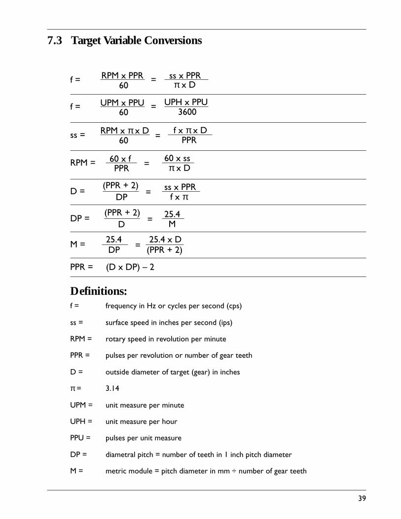
Definitions:f = frequency in Hz or cycles per second (cps)
ss = surface speed in inches per second (ips)
RPM = rotary speed in revolution per minute
PPR = pulses per revolution or number of gear teeth
D = outside diameter of target (gear) in inches
π = 3.14
UPM = unit measure per minute
UPH = unit measure per hour
PPU = pulses per unit measure
DP = diametral pitch = number of teeth in 1 inch pitch diameter
M = metric module = pitch diameter in mm ÷ number of gear teeth
7.3 Target Variable Conversions

40
Warranty and Return ShipmentsStatement
The materials ordered and agreed to be furnished by Seller are warranted against defect of material or workmanship for a period of(1) year from the date of shipment, or for their rated life (whichever period ends first). Seller’s obligation under the warranty is limitedto repair or replacement, in Seller’s option, of the defective material at Seller’s factory (point of shipment) and does not extend toequipment other than of Seller’s factory (point of shipment) and does not extend to equipment other than of Seller’s manufacture. Thewarranty shall not apply to any product or part which has been subject to misuse, negligence, accident, or attempted or unauthorizedrepair or modification. All return shipments must be factory authorized prior to shipment, and shipment will be at buyer’s expense.The only statutory warranties applicable to the materials are warranties of title and that the materials will be merchantable and, ifmanufactured to Buyer’s specifications, that the said items conform to such specifications. UNLESS EXPRESSLY STATED ON THEFACE HEREOF, NO WARRANTY OF FITNESS FOR ANY PARTICULAR PURPOSE IS TO BE IMPLIED, NOR ARE ANY OTHERWARRANTIES WHICH EXTEND BEYOND THOSE STATED HEREIN. SELLER’S SOLE LIABILITY FOR DEFECTS OR BREACH OFWARRANTY SHALL BE REPLACEMENT OF THE MATERIALS INVOLVED, AND IN NO EVENT WILL THE SELLER BE LIABLE FORSPECIAL OR CONSEQUENTIAL DAMAGES. FAILURE TO TEST, INSPECT AND MAKE CLAIMS FOR BREACH OF WARRANTYWITHIN REASONABLE PERIODS SHALL BE CONCLUSIVE EVIDENCE THAT THE MERCHANDISE SHIPPED IS SATISFACTORYIN ALL RESPECTS AND SUPPLIED IN ACCORDANCE WITH ORDERED SPECIFICATIONS.
LIMITATION OF LIABILITY: (a) SELLER DOES NOT UNDER ANY CIRCUMSTANCES, WHETHER AS A RESULT OF BREACH OFCONTRACT, BREACH OF WARRANTY, TORT OR OTHERWISE BE LIABLE FOR CONSEQUENTIAL, INCIDENTAL, SPECIAL OREXEMPLARY DAMAGES, including, but not limited to, loss of profits or revenues, loss of use of or damage to any associatedequipment , cost of capital, cost of substitute products, facilities or services, downtime costs, or claims of Buyer’s customers. (b)SELLER’S LIABILITY ON ANY CLAIM OF ANY KIND FOR ANY LOSS OF DAMAGE ARISING OUT OF, RESULTING FROM, ORCONCERNING ANY ASPECT OF THIS AGREEMENT OR FROM THE PRODUCTS OR SERVICES FURNISHED HEREUNDERSHALL NOT EXCEED THE PRICE OF THE SPECIFIC ORDER OR SHIPMENT WHICH GIVES RISE TO THE CLAIM.
Notice Regarding Damage
These units were carefully packed in compliance with carrier regulations and thoroughly inspected before leaving our delivery plant.Responsibility for their safe delivery was assumed by the carrier upon acceptance of the shipment. Claims for loss or damagesustained in transit must, therefore, be made upon the carrier.
Concealed Loss or Damage
Concealed loss or damage means loss or damage which does not become apparent until the merchandise has been unpacked. Thecontents may be damaged in transit due to rough handling even through the package may not show external damage. When damage isdiscovered upon unpacking, make a request for inspection by the carrier’s agent. Then file a claim with the carrier since such damage isthe carrier’s responsibility.
Visible Loss or Damage
Any external evidence of loss or damage must be noted on the freight bill or express receipt and signed by the carrier’s agent. Failureto properly describe evidence of loss or damage may result in the carrier refusing to honor a claim. We definitely are not responsiblefor any damage incurred while merchandise is in transit. The transportation company will settle promptly all claims as they are insuredand their rates cover this cost. Any correspondence in regard to loss or damage must be accompanied by a copy of the carrier’sreport.

41
IndexA
active sensor, connection ................................................. 12active sensor, orientation ................................................... 8adaptive period averaging ............................................ 1, 30adjusting potentiometers .......................................... 33, 34Alarm condition ............................................................... 24Analog Full Scale Frequency (AF) ................................ 20analog meter ....................................................................... 18analog output .............................................................. 19, 22analog sine wave ................................................................ 11Analog Zero Scale Frequency (A0) ............................... 19
B
battery chargers ................................................................... 6
C
Calibrate Frequency (CF) ............................................... 23calibration constant .......................................................... 17Characteristics of Operation .......................................... 17Connecting a Passive Sensor ........................................... 11Connecting an Active Sensor ......................................... 12Connecting the Power Supply ................................ 13, 15constant ........................................ 16, 12, 17, 22, 23, 29, 36constants, recorded stored ............................................... 43control panel .................................................................. 1, 16current loop ....................................................................... 19cursor ........................................................................... 16, 32
D
data acquisition time ........................................................ 29data acquisitions ................................................................ 29dead band ............................................................................ 28delayed trip ........................................................................ 30descriptor ........................................................ 16, 17, 32, 33digital square wave ............................................................ 11Display Digits for Frequency Constants (FS, A0, AF, CF,S1 through S4) ......................................... 18, 19, 20, 22, 26Display Digits for Hysteresis and Type Constants (H1through H4) ....................................................................... 28Display Digits for Special Constant (SP) ...................... 22
E
EAROM ............................................................................... 1electrical noise generating equipment ............................. 6Entering the Constants .................................................... 32Environmental .................................................................. 35expanded scale .................................................................... 21
exponent ............................................................................. 16external reset ...................................................................... 30
F
filter switches ..................................................................... 34full scale frequency (FS) ................................................... 18calculating ........................................................................... 18
G
glossary ............................................................................... 37H
How to Use this Manual ................................................... 3Hysteresis (H1-H4), bias, type & magnitude .............. 28hysteresis constant ............................................................ 28
I
input frequency ......................................... 1, 19, 22, 29, 30input signal frequency, formula ..................................... 18input type passive or active ............................................. 28Installation and Wiring Guidelines ................................. 6internal control panel ................................................... 1, 16Introduction ......................................................................... 1inverted scale ...................................................................... 20
J
jitter .................................................................................. 21
K
keys, UP-Arrow, RT-Arrow .......................................... 16
L
latching relay ...................................................................... 31location ................................................................................. 8location, mounting ............................................................. 7loss or damage ...................................................................... 5Lowest Measured Frequency .......................................... 22
M
Meter Full Scale Frequency (FS) .................................... 19meter output ...................................................................... 19Mounting and Wiring Procedures ................................... 6Mounting TACH-PAK 3 .................................................. 7Mounting the Speed Sensor .............................................. 8

42
O
operational constants ....................................................... 17Optional Circuits, relay reset / verify .......................... 12Outputs ............................................................................... 35Overspeed setpoints ............................................ 24, 25, 26Overview .............................................................................. 1
P
Package Contents ................................................................ 5passive speed sensor .......................................................... 11power cord .................................................................. 14, 15power line ............................................................................. 6PPR .................................................................................. 18program mode ................................................................... 32protective subcover ...................................................... 9, 14
R
radiated electrical noise ...................................................... 6Reference ............................................................................ 35reset, type L relay ............................................................. 30right arrow key ................................................................. 32round a number ................................................................ 16RPM .................................................................................. 18
S
scaling resistor .................................................................... 21Scientific Notation .............................................. 16, 17, 21setpoint classification ....................................................... 24Setpoint Frequency (S1-S4) ............................................. 26shield connections ......................................................... 6, 10sign, in display ................................................................... 32Signal Input ........................................................................ 34signal leads .......................................................................... 10significant digit .................................................................. 16span of expanded scale ..................................................... 21Special Constant (SP) ....................................................... 22Specifications ..................................................................... 34speed sensor ........................................................... 2, 3, 8, 11speed sensor, clearance ....................................................... 8standard constants ............................................................. 17store, constants .................................................................. 33
T
target .................................................................................... 1TB1 ................................................................. 9, 10, 14, 15TB2 ....................................................................... 6, 19, 10terminal block assignments ............................................. 10The Constants ................................................................... 17timed-out ............................................................... 30, 31, 38time-out period .................................................................. 22TTL .................................................................................. 34TTL sensors ....................................................................... 12twisted pairs ................................................................. 6, 10Types of Speed Sensors .................................................. 11
U
Underspeed setpoints .......................................... 24, 25, 27Unpacking Instructions ..................................................... 5
V
verify, calibrate .................................................................. 23
W
Warranty ............................................................................ 40Wiring Connections ........................................................... 9

43
Recorded Stored Constants
Descriptor Section Constant
FS
AO
AF
CF
S1
H1
S2
H2
S3
H3
S4
H4
SP
F S
A 0
A F
C F
S 1
H 1
S 2
H 2
S 3
H 3
S 4
H 4
S P
5.3.1
5.4.1
5.5.1
5.7.1
5.10.1
5.10.1
5.10.1
5.11.1
5.10.1
5.11.1
5.10.1
5.11.1
5.6.1