table of contents - fordservicecontent.com stroke diesel engine your new diesel engine will feel,...
TRANSCRIPT

Introduction 2
Instrument Cluster 6
Driving 8
Roadside Emergencies 16
Cleaning 18
Maintenance and Specifications 20
Scheduled Maintenance Guide 69
Index 94
All rights reserved. Reproduction by any means, electronic or mechanicalincluding photocopying, recording or by any information storage and retrievalsystem or translation in whole or part is not permitted without writtenauthorization from Ford Motor Company. Ford may change the contents withoutnotice and without incurring obligation.
Copyright © 2010 Ford Motor Company
Table of Contents
1
2011 Diesel (eco)Supplement, 5th PrintingUSA (fus)

POWER STROKE DIESEL ENGINEYour new diesel engine will feel, drive and function somewhat differentlythan a gasoline engine. Therefore it is very important that you read andthoroughly familiarize yourself and others operating the vehicle with thisguide. A special procedure for turning off the diesel engine is in theDriving chapter. It is important to read and understand thismaterial in order to maintain the best service life for your engine.
This guide will acquaint you with the Power Stroke diesel engine. Itprovides recommendations on engine care and operating procedures. Forcomplete vehicle information, also refer to the Owner’s Guide includedwith the vehicle. It also describes equipment and gives specifications forequipment that was in effect when this guide was approved for printing,and should be considered a permanent part of the vehicle.Some aftermarket products may cause severe engine/transmissionand/or exhaust system damage; refer to the Warranty Guide for moreinformation. Your vehicle’s powertrain control systems can detectand store information about vehicle modifications that increasehorsepower and torque output such as whether or notperformance-enhancing powertrain components commonly referredto as “performance chips” have been used. This information cannotbe erased and will stay in the system’s memory even if themodification is removed. The information can be retrieved by FordMotor Company, Ford of Canada, and service and repair facilitieswhen servicing your vehicle. This information may be used todetermine if repairs will be covered by warranty.
Ford may discontinue models or change specifications without any noticeand without incurring obligations.
Important noticeFord vehicles are suitable for producing ambulances only if equippedwith the Ford ambulance preparation package. In addition, Ford urgesambulance manufacturers to follow the recommendation of the FordIncomplete Vehicle Manual, Ford Truck Body Builder’s Layout Book(and pertinent supplements) and the Qualified Vehicle ModifiersGuidelines. Using a Ford vehicle without the Ford ambulancepreparation package to produce an ambulance voids the Ford warrantyand could result in elevated underbody temperatures, fueloverpressurization and the risk of fuel expulsion and fires. To determinewhether the vehicle is equipped with the Ford ambulance preparationpackage, inspect the information plate on the driver’s side door pillar.Contact the manufacturer of your vehicle to determine whether theambulance manufacturer’s followed Ford’s recommendations.
Introduction
2
2011 Diesel (eco)Supplement, 5th PrintingUSA (fus)

WARNINGS
Throughout this guide, you will find warnings identified by thesymbol . Warnings remind you to be especially careful to reduce therisk of personal injury.
NEW VEHICLE BREAK-INYour vehicle does not need an extensive break-in. Try not to drivecontinuously at the same speed for the first 1,000 miles (1,600 km) ofnew vehicle operation. Vary your speed to allow parts to adjustthemselves to other parts.
Drive your new vehicle at least 500 miles (800 km) before towing atrailer. Make sure you use the specified engine oil by checking the engineoil specification chart under Engine oil in the Maintenance andSpecifications chapter.
Do not add friction modifier compounds or special break-in oils duringthe first few thousand miles (kilometers) of operation, since theseadditives may prevent piston ring seating. See Engine oil in theMaintenance and Specifications chapter of this supplement for moreinformation on oil usage.
DIESEL ENGINE INFORMATIONThe diesel engine fuel system is a pressurized two-stage filtration systemand consists of:
• a frame-mounted diesel fuel conditioner module (DFCM) / primaryfilter with an electric fuel pump and water drain,
• an engine-mounted secondary fuel filter,• a fuel injector for each cylinder (8 total),• a high-pressure fuel pump,
• a high-pressure fuel rail for each cylinder bank (2 total) and
• numerous high-pressure pipes from the high-pressure pump to therails, and rails to the injectors.
The DFCM acts as a primary fuel filter/water separator which removesboth water and impurities from the fuel. The engine mounted filter filtersfiner impurities from the diesel fuel. The engine-mounted fuel filter andthe DFCM filter should be changed at the recommended service intervalor when indicated by the message center LOW FUEL PRESSUREmessage. Refer to the scheduled maintenance information in thissupplement for more information.
Introduction
3
2011 Diesel (eco)Supplement, 5th PrintingUSA (fus)

The DFCM should be drained at regular intervals or when indicated bythe message center message and water in fuel indicator light. See Fuelfilter/water separator in the Maintenance and Specifications chapter.
The fuel injection system is controlled through the powertrain controlmodule (PCM).
Fuel is drawn from the fuel tank by a frame-mounted electric fuel pumplocated inside the DFCM and provides pressurized fuel to the engine.The fuel pump contains a pressure relief valve for overpressureprotection in the event of restricted flow.
Engine protection mode
Ford diesel engines are equipped with engine protection and emissioncontrol systems. These systems monitor critical temperatures andpressures, and modify engine operation accordingly. These features areintended to modify engine performance characteristics. If these modifiedengine performance characteristics persist for an extended period or theservice engine soon or powertrain malfunction/reducedpower/electronic throttle control light is illuminated, seek servicefrom your authorized dealer.
Lubrication system
It is important to change the engine oil at the recommended serviceintervals to maintain oil viscosity. Extending the oil and filter changeinterval beyond the recommended interval can negatively affect engineperformance, fuel economy and engine life. Refer to Engine oil in theMaintenance and Specifications chapter.
Fast start glow plug system
The diesel engine glow system consists of:
• eight glow plugs (one per cylinder)
• the glow plug control module (GPCM)
• engine coolant temperature (ECT) sensor
• barometric pressure (BARO) sensor
• environmental temperature sensor
Introduction
4
2011 Diesel (eco)Supplement, 5th PrintingUSA (fus)

The glow plug system iselectronically controlled by the PCMand GPCM. The GPCM energizes theglow plugs immediately after theignition is turned on and kept on as determined by the GPCM using theECT, BARO and environmental temperature sensor. The required timefor the glow plugs to be energized decreases as the coolant temperature,barometric pressure and environmental temperature increase.
Engine and secondary cooling systemThe cooling system contains an engine cooling loop to cool the engineand a secondary cooling loop to cool the transmission, exhaust gasrecirculation (EGR), charge air and fuel. The coolant serves threeprimary purposes: to provide heat transfer, freeze point protection, andcorrosion protection using additives.
Vehicles with diesel engines typically are used to carry heavy loads andaccumulate mileage rapidly. These two factors may cause the additives inthe coolant to “wear out” in a shorter time. Refer to the Specialoperating conditions section for more information about coolantadditives and coolant change intervals. Operating the engine withinsufficient coolant and/or coolant additive can cause severe enginedamage.
Selective catalytic reduction (SCR) systemYour vehicle is equipped with a selective catalytic reduction (SCR)system to help reduce emission levels of oxides of nitrogen from theexhaust of the diesel engine. This system relies on the use of dieselexhaust fluid (DEF) which must be replenished at certain intervals.Failure to maintain proper DEF levels or if the DEF becomescontaminated will result in vehicle speed limitations and/or result in thevehicle entering an idle-only mode. See Selective catalytic reduction(SCR) system in the Maintenance and Specifications chapter for moreinformation.
Speed control (if equipped)If vehicle speed goes outside a predetermined range from the set speed,the RES (Resume) function will not reset vehicle speed. Vehicle speedwill need to be reset with the SET +/- button after reaching desiredspeed using accelerator pedal.
Introduction
5
2011 Diesel (eco)Supplement, 5th PrintingUSA (fus)

WARNING LIGHTS
Base cluster with standard measure shown; metric and optionalsimilar
Note: Some warning lights are reconfigurable telltale (RTT) indicatorlights and will illuminate in the message center display and function thesame as the other warning lights.
Glow plug pre-heat indicator:
With the key in the on position, thislight will illuminate if glow plug heatis necessary as a starting aid. Wait until the light goes off before starting.Refer to Cold weather starting in the Driving chapter of thissupplement. After the engine starts, the light should turn off. The lightshould always illuminate at least momentarily when the engine is coldand the ignition is turned to on.
0 4 C H C H E F
RPM x 1000
020
40
60 80 100120140
160
km/hMPH
Instrument Cluster
6
2011 Diesel (eco)Supplement, 5th PrintingUSA (fus)

Water in fuel:
During refueling, it is possible forwater-contaminated diesel fuel to bepumped into your tank. Yourvehicle’s fuel system is equippedwith a fuel filter/water separator to remove water from the fuel. Thewater in fuel light will illuminate when the DFCM has a significantquantity of water in it.
If the light illuminates when the engine is running, stop the vehicle assoon as safely possible, shut off the engine, then drain the DFCM. Referto Fuel filter/water separator in the Maintenance and Specificationschapter of this supplement for the drain procedure. Allowing water tostay in the system could result in extensive damage to, or failure of, thefuel injection system.
Note: Air will enter into the fuel system if the DFCM is drained whilethe system is running. The engine will not operate properly if air entersthe system.
WARNING: Do not drain the DFCM while the engine is running.Fuel may ignite if the separator is drained while the engine is
running or the vehicle is moving.
Low/contaminated diesel exhaust fluid:
With the key in the on position, thislight will illuminate if the exhaustfluid is contaminated and/or low.See Diesel exhaust fluid in theMaintenance and Specificationschapter for more information.
GAUGESEngine boost gauge:
Indicates the amount of manifold airpressure in the engine.
Instrument Cluster
7
2011 Diesel (eco)Supplement, 5th PrintingUSA (fus)

STARTING THE ENGINERead all starting instructions carefully before you start your vehicle.
For temperatures below 32°F (0°C), the use of the correct grade engineoil is essential for proper operation. Refer to Engine oil specificationsin the Maintenance and Specifications chapter for more information.
Your vehicle may be equipped with a cold weather starting strategy thatprevents severe engine damage by assisting in engine lubricationwarm-up. In extremely cold ambient temperatures, this strategy activatesand prevents the accelerator pedal from being used for 30 seconds afterstarting the vehicle. By not allowing the accelerator pedal to be used, theengine oil is allowed to properly lubricate the bearings preventing enginedamage due to lack of proper lubrication. After the 30 second warm-upperiod, the accelerator pedal will be operational again as long as thepedal is not being pressed when the 30 second time limit expires. Whenstarting the engine in extremely cold temperatures (-15°F [–26°C]), it isrecommended to allow the engine to idle for several minutes beforedriving the vehicle.
Ensure the gearshift lever is in P (Park) and the parking brake is fullyset before you turn the key. Do not press the accelerator during starting.
Engine-driven cooling fan (fan clutch)Your vehicle is equipped with an engine driven cooling fan drive (alsocalled a fan clutch). This fan drive changes the fan speed to match thevehicle’s changing cooling air flow requirements. Fan speed, fan noiselevel and fuel consumption all will increase based on the drivingconditions that include trailer towing, hill climbing, heavy loads, highspeed and high ambient temperature, individually or in combination.
The fan drive is designed to provide the minimum fan speed (andresulting minimum fan noise and fuel consumption) required to meet theever changing vehicle cooling air flow requirements. You will hear theamount of fan noise increasing and decreasing as the engine powerrequirements and vehicle driving conditions change as you drive. This isto be expected as being normal to the operation of your vehicle. Highlevels of fan noise might also be heard when your engine is first started,and should normally decrease after driving for a short time.
Driving
8
2011 Diesel (eco)Supplement, 5th PrintingUSA (fus)

If the vehicle’s speed is limited or the vehicle has entered anidle-only modeIf the vehicle’s speed is limited or in an idle-only mode, the SCR systemmay be limiting the vehicle’s functions due to low or contaminated dieselexhaust fluid (DEF). Check the DEF. See Selective catalytic reduction(SCR) system in the Maintenance and Specifications chapter for moreinformation.
Cold weather startingIt is recommended that the engine block heater be used for startingwhen the temperature is -10°F (-23°C) or colder. Refer to Engine blockheater (if equipped) in the Driving chapter of the Owner’s Guide.
When operating in cold weather, use Motorcraft� cetane improvers ornon alcohol-based cetane improvers from a reputable manufacturer.
Do not crank the engine for more than 10 seconds as starter damagemay occur. If the engine fails to start, turn the key to 3 (off) and wait30 seconds before trying again.
WARNING: Do not use starting fluid, such as ether, in the airintake system (see air filter decal). Such fluid could cause
immediate explosive damage to the engine and possible personal injury.
WARNING: Do not add gasoline, gasohol or alcohol to dieselfuel. This practice creates a serious fire hazard and causes
engine performance problems.
1. Turn the key to on without turning the key to start. Do not start the
engine until the glow-plug pre-heat indicator turns off.
2. When the glow plug pre-heatindicator turns off, turn the key tostart, then release the key as soonas the engine starts. The glow plugsmay remain on for a period of time after engine start. If the engine is notstarted before the glow plug activation time ends, the glow plugs willneed to be reset by turning the key to off.
3. After the engine starts, allow it to idle for about 15 seconds. Thisis to protect the engine. Do not increase engine speed until the oilpressure gauge indicates normal pressure.
Driving
9
2011 Diesel (eco)Supplement, 5th PrintingUSA (fus)

ENGINE IDLE SHUTDOWN (IF EQUIPPED)Your vehicle may be equipped with an engine idle shutdown system. Thissystem will automatically shut down your engine when it has been idlingin P (Park) or N (Neutral) for five minutes (parking brake set) or15 minutes (parking brake not set). When the engine idle shutdownprocess has started:• A chime will sound and the message center will display ENGINE
TURNS OFF IN 30 (seconds) and start counting down.• The 5 or 15 minute timer can be restarted by changing the position of
the accelerator pedal, brake pedal or the park brake within the final30 seconds.
• When the timer reaches zero, the engine shuts down and the messagecenter will display ENGINE TURNED OFF.
• One minute after the engine has shut down, the electrical system willsimulate key off, even though the ignition is still in the on position,initiating normal accessory delay period.
• The ignition must be moved to the off position to reset the systembefore restarting the vehicle.
Note: The engine idle shutdown idle timer will not start if:
• The engine is operating in power take-off (PTO) mode.
• The engine coolant temperature is below 60°F (16°C).
• The exhaust emission control device (DPF) is regenerating.
STOPPING THE ENGINETurn the ignition to the off position.
To prolong engine life (especially after extended high speed, highambient temperature, or high GVW/GCW operation), it is recommendedthat a hot engine be idled for 3-5 minutes which will allow theturbocharged engine to cool down.
COLD WEATHER OPERATIONChanging to a lighter grade engine oil also makes starting easier underthese conditions. Refer to Engine oil specifications in the Maintenanceand Specifications chapter of this supplement.
Diesel fuel is adjusted seasonally for cold temperatures. Diesel fuel whichhas not been properly formulated for the ambient conditions may formwax crystals which can clog the fuel filters. At temperatures below 20°F(–7°C), if the engine starts, stalls after a short time, and then will not
Driving
10
2011 Diesel (eco)Supplement, 5th PrintingUSA (fus)

restart, the fuel filter(s) may be clogged. For best results in coldweather, use a diesel fuel which has been formulated for the ambientconditions. If you have been using biodiesel, you may need to use a fuelwith lower biodiesel content, try another brand, or discontinue usingbiodiesel.Your vehicle is equipped with a diesel fuel conditioner module (DFCM)which recirculates fuel from the engine to help prevent fuel filterclogging. Your vehicle is also equipped with a bypass relief valve, locatedin the fuel tank pick-up boot, which provides fuel flow to the engine ifthe fuel pickup should become plugged. To allow the bypass valve tofunction and avoid engine fuel starvation during cold weather operationof 32°F (0°C) or below, it is recommended that the fuel level in yourtank should not be allowed to drop below 1⁄4 full. This will help preventair from entering the fuel system and stalling the engine.Your vehicle is equipped with a an SCR system which uses diesel exhaustfluid (DEF) to operate properly. DEF must be replenished at certainintervals. When filling the vehicle’s DEF tank in cold weather, specialcare must be taken to prevent damage to the DEF tank. For proper coldweather fill procedure, see Selective Catalytic Reduction (SCR) Systemin the Maintenance and Specifications chapter.
In cold weather below 32°F (0°C), the engine will slowly increase to ahigher idle speed if left idling in P (Park). As the engine warms-up, theengine sound level will decrease due to the activation of PCM-controlledsound reduction features.
If your vehicle is operated in a heavy snow storm or blowing snowconditions, the engine air induction may become partially clogged withsnow and/or ice. If this occurs, the engine may experience a significantreduction in power output. At the earliest opportunity, clear all the snowand/or ice away from inside the air filter assembly. Remove the aircleaner cover and the pleated paper filter, leaving the foam filter in andremove any snow or ice. Ensure the foam filter is installed correctly inplace. Remove any debris, snow and/or ice on the foam filter by brushingthe surface with soft brush. Do not use water, solvents, or a hard brushfor cleaning the foam filter.
In order to operate the engine in temperatures of 32°F (0°C) or lower,read the following instructions:
• Make sure that the batteries are of sufficient size and are fullycharged. Check other electrical components to make sure they are inoptimum condition.
• Use the proper coolant solution at the concentration recommended toprotect the engine against damage from freezing.
Driving
11
2011 Diesel (eco)Supplement, 5th PrintingUSA (fus)

• Try to keep the fuel tank full as much as possible at the end ofoperation to prevent condensation in the fuel system.
• Make sure you use proper cold weather engine oil and that it is at itsproper level. Also, if necessary, make sure to follow the engine oil andfilter change schedule found under the Special operating conditionssection listed in the scheduled maintenance information.
• At temperatures of -10°F (-23°C) or below, it is recommended thatyou use an engine block heater to improve cold engine starting.
• If operating in arctic temperatures of -20°F (-29°C) or lower, consultyour truck dealer for information about special cold weatherequipment and precautions.
Note: Idling in cold weather will not heat the engine to its normaloperating temperature. Long periods of idling, especially in cold weather,can cause a buildup of deposits which can cause engine damage.
The following cold weather idling guidelines are recommended:
• Use Motorcraft� cetane improvers or non alcohol-based cetaneimprovers from a reputable manufacturer.
• Maintain the engine cooling system properly.
• Avoid shutting the engine down after an extensive idling period. Drivethe vehicle for several miles with the engine at normal operatingtemperatures under a moderate load.
• Consider using an engine block heater.
• For extended idle times use an approved idle speed increase device.
Winter operating tips for Arctic operation -20°F (-29°C) and belowThe following information is provided as a guideline only, and is notintended to be the only source of possible solutions in resolving extremecold temperature issues.
Starting aids:The use of the factory engine block heater (if equipped) (refer toEngine block heater in the Driving chapter of the Owner’s Guide) willassist in engine starting in extreme cold ambient temperatures.
WARNING: Do not use starting fluid, such as ether, in the airintake system (see air filter decal). Such fluid could cause
immediate explosive damage to the engine and possible personal injury.
Driving
12
2011 Diesel (eco)Supplement, 5th PrintingUSA (fus)

Idle control:• Your vehicle may have a factory option for a stationary elevated idle
control (SEIC) through dash-mounted upfitter switches will allow theoperator to elevate the idle rpm for extended idle periods, as well asaftermarket equipment such as PTO operation. This feature must beconfigured even if ordered from the factory. See your authorizeddealer for required upfitting.
Operation in snow and rainVehicle operation in heavy snowfall or extreme rain conditions may feedexcessive amounts of snow/water into the air intake system. This couldplug/soak the air filter with snow and may cause the engine to losepower and possibly shut down.
The following actions are recommended after operating the vehicle up to200 miles (320 km) in snowfall or extreme rain:
• Snow: At the earliest opportunity, open the hood and clear all thesnow and ice from the air filter housing inlet (do not remove the foamfilter) and reset the air filter restriction gauge.
Note: Removal of the foam filter degrades vehicle performance duringsnow and hot weather conditions.
• Extreme rain: The air filter will dry after about 15–30 minutes athighway speeds. At the earliest opportunity, open the hood and resetthe air filter restriction gauge.
Refer to Air filter and restriction gauge in the Maintenance andSpecifications chapter of this supplement for more information.
Operation in standing waterIngestion of water into the diesel engine can result in immediate andsevere damage to the engine. If driving through water, slow down toavoid splashing water into the intake. If the engine stalls, and ingestionof water into the engine is suspected, do not try to restart the engine.Consult your dealer for service immediately.
Engine block heater (if equipped)Refer to the Driving chapter in the Owner’s Guide.
Driving
13
2011 Diesel (eco)Supplement, 5th PrintingUSA (fus)

Rapid heat supplemental heating system (if equipped)The optional rapid heat feature is an electrically powered device that isdesigned to provide supplemental heat during engine warm up. Formaximum effectiveness mid to low blower speed is recommended duringinitial warm up. When operating in automatic mode (when equipped) theclimate control unit will determine the appropriate blower speed forexisting conditions.
Note: Additional aftermarket electrical loads operated during enginewarm up may impact the performance of the rapid heat supplementalheater.
DUAL FUEL TANK SELECTOR CONTROL (IF EQUIPPED)If your vehicle is equipped with dualfuel tanks, you will have a selectorcontrol, located to the right of thesteering wheel, which allows you todraw fuel from either tank. Your fuelgauge and the DTE (distance toempty) will display the amount offuel in the currently selected tank.
ENGINE-EXHAUST BRAKINGThis feature increases engine braking at higher engine speeds to providebetter grade descent control with less brake and transmission wear andtear.
This feature is integrated with the tow/haul mode feature. When tow/haulmode is switched on, the engine-exhaust braking feature will also beactive. For more information on tow/haul, see Automatic transmissionoperation in the Owner Guide.
Driving
14
2011 Diesel (eco)Supplement, 5th PrintingUSA (fus)

TRAILER TOWINGRefer to your Owner’s Guide for full details on towing a trailer.
Trailer towing tables
Vehicle type Rear axle
ratio
Maximum
GCWR - lb (kg)
F–250/F–350 Single Rear Wheel(SRW)
3.31/3.55/3.73 23500 (10659)
F–350 Dual Rear Wheel (DRW)Chassis Cab
3.73/4.10 24500 (11113)
F–350 Dual Rear Wheel (DRW)Pick-up
3.73 30000 (13608)
F–450 Chassis Cab 4.10 26000 (11793)4.30 30000 (13608)*
F-450 Pick-up 4.30 33000 (14969)F-550 (17500/18000 lb GVWR) 4.10/4.88 26000 (11793)F-550 (19000/19500 lb GVWR) 4.30/4.88 35000 (15875)*
* Requires optional GCWR package
Driving
15
2011 Diesel (eco)Supplement, 5th PrintingUSA (fus)

FUEL PUMP SHUT-OFF SWITCHThis device stops the electric fuel pump from sending fuel to the enginewhen your vehicle has had a substantial jolt.
After an accident, if the engine cranks but does not start, this switchmay have been activated.
This switch is located on thepassenger’s side of the instrumentpanel. Open the front passengerdoor and remove the small accesspanel
The switch has a red button on topof it.
To reset the switch:
1. Turn the ignition off.
2. Check the fuel system for leaks.
3. If no leaks are apparent, reset the switch by pushing in on the resetbutton.
4. Turn the ignition on.
5. Wait a few seconds and return the key to off.
6. Make another check for leaks.
Roadside Emergencies
16
2011 Diesel (eco)Supplement, 5th PrintingUSA (fus)

JUMP STARTING YOUR VEHICLEThe 6.7 diesel engine can be jump started using the same procedure as agasoline engine. Use the primary battery (battery located on thepassenger side) for any jump starting procedure and refer to yourOwner’s Guide for the proper method of jump starting.
RUNNING OUT OF DEF (DIESEL EXHAUST FLUID)If your vehicle runs out of DEF, it will enter into a speed limited modeand can also enter into an idle-only mode. Normal vehicle operation willnot resume until DEF is refilled. See the Selective Catalytic Reduction(SCR) System section in the Maintenance and Specifications chapterfor more information.
Contact roadside assistance for help in finding a retailer that sells DEF.See the Customer Assistance chapter in the Owner’s Guide for moreinformation.
Roadside Emergencies
17
2011 Diesel (eco)Supplement, 5th PrintingUSA (fus)

ENGINE
Engines are more efficient when they are clean because grease and dirtbuildup keep the engine warmer than normal. When washing:
• Take care when using a power washer to clean the engine. Thehigh-pressure fluid could penetrate the sealed parts and causedamage.
• Do not spray a hot engine with cold water to avoid cracking theengine block or other engine components.
• Spray Motorcraft� Engine Shampoo and Degreaser (ZC-20) on allparts that require cleaning and pressure rinse clean.
• Never wash or rinse the engine while it is running; water in therunning engine may cause internal damage.
• Cover the highlighted areas to prevent water damage when cleaningthe engine.
Cleaning
18
2011 Diesel (eco)Supplement, 5th PrintingUSA (fus)

EXHAUST
The visible holes in each leg of the twin tip and the holes under the shieldjust inboard of the right rear tire(s) are functional. The holes need to bekept clear of mud/debris or foreign material to maintain proper function ofthe exhaust system. Clean and remove debris or foreign material if presentas needed. Spraying with a hose during regular washing of vehicle shouldhelp keep holes clean and clear of debris or foreign material.
WARNING: Failure to maintain the functional holes, in thetailpipe section of the exhaust, clean and free of debris or
foreign material may result in the holes becoming blocked or plugged.Do not modify or remove the tail-pipe section. Blocked or pluggedholes or removal/modification of the system could result in elevatedexhaust gas temperatures which may result in vehicle/property damageor personal injury
WARNING: The normal operating temperature of the exhaustsystem is very high. Never work around or attempt to repair any
part of the exhaust system until it has cooled. Use special care whenworking around the diesel oxidation catalytic converter and/or the dieselparticulate filter (DPF). The diesel oxidation catalytic converter and/orthe DPF heats up to a high temperature after only a short period ofengine operation and can stay hot even after the engine is turned off.Failure to follow these instructions may result in personal injury.
Cleaning
19
2011 Diesel (eco)Supplement, 5th PrintingUSA (fus)

IDENTIFYING COMPONENTS IN THE ENGINE COMPARTMENT
F-Super Duty
1. Engine oil dipstick2. Automatic transmission dipstick3. Brake fluid reservoir4. Power distribution box5. Batteries6. Engine cooling system coolant reservoir (primary high-temperaturecooling system)7. Power steering fluid reservoir8. Engine oil fill9. Engine-mounted fuel filter assembly10. Secondary cooling system coolant reservoir11. Air filter assembly
12. Air filter restriction gauge
13. Windshield washer fluid reservoir
113 5 2 3 4
57 691012 11 8
Maintenance and Specifications
20
2011 Diesel (eco)Supplement, 5th PrintingUSA (fus)

SCHEDULED MAINTENANCEThe scheduled maintenance services in the scheduled maintenanceinformation of this supplement are required because they areconsidered essential to the life and performance of your vehicle.
Use only recommended fuel, lubricants, fluids and service partsconforming to Ford specifications. Motorcraft� parts are designed andbuilt for best performance in your vehicle.
FUEL REQUIREMENTS - CHOOSING THE RIGHT FUEL: VEHICLESOPERATED WHERE ULTRA LOW SULFUR DIESEL FUEL ISREQUIRED (UNITED STATES/CANADA/PUERTO RICO/U.S. VIRGINISLANDS AND OTHER LOCALES)Use only Ultra Low Sulfur (15 ppm Sulfur Maximum) number 1-Dor 2-D diesel fuel (also known as ULSD) in your 6.7L dieselengine. The engine and exhaust system were designed to only use thisfuel. Look for the ULTRA-LOW SULFUR HIGHWAY DIESEL FUEL(15 ppm Sulfur Maximum) label on fuel pumps when purchasing yourfuel.
Using low sulfur diesel fuel (16-500 ppm) or high sulfur dieselfuel (greater than 500 ppm) in a diesel engine designed to useonly Ultra Low Sulfur Diesel fuel will cause certain emissioncomponents to malfunction which may also cause the service
engine soon light to illuminate indicating an emissions-
related concern.
Diesel fuel is adjusted seasonally for cold temperature. For best resultsat temperatures below 20°F (-7°C), it is recommended to use a dieselfuel which has been seasonally adjusted for the ambient conditions. SeeCold weather operation in the Driving chapter of this supplement.
FUEL REQUIREMENTS - CHOOSING THE RIGHT FUEL: VEHICLESOPERATED WHERE ULTRA LOW SULFUR DIESEL FUEL IS NOTREQUIREDFor the engine to operate reliably on low sulfur or high sulfur diesel fuel,the engine must be a high sulfur configured engine or a ULSDfuel-configured engine that has been retrofitted for high sulfur diesel fueluse.
Maintenance and Specifications
21
2011 Diesel (eco)Supplement, 5th PrintingUSA (fus)

Use only a diesel engine that has been configured for use withhigh sulfur diesel fuel in markets with diesel fuel that has sulfurcontent greater than 15 ppm. Using low sulfur diesel fuel (16–500ppm) or high sulfur diesel fuel (greater than 500 ppm) in a dieselengine designed to use only Ultra Low Sulfur Diesel fuel mayresult in damage to engine emission control devices and theaftertreatment system, potentially rendering the vehicleinoperable. Engine damage from using the improper type of fuelis not covered under your warranty.
Vehicles with engines configured for use with high sulfur diesel fuel willonly be made available for sale in countries where ULSD fuel is generallynot available or mandated by the government. Vehicles originally sold ina ULSD fuel market that are subsequently exported to non-ULSD fuelmarkets will need to be retrofitted (at the customer’s expense) in orderto be reliably operated on non-ULSD fuel.
Diesel fuel is adjusted seasonally for cold temperature. For best resultsat temperatures below 20°F (-7°C), it is recommended to use a dieselfuel which has been seasonally adjusted for the ambient temperature.See Cold weather operation in the Driving chapter of this supplement.
BIODIESELThis vehicle may be operated on diesel fuels containing up to 20%biodiesel, also known as B20.
To help achieve acceptable engine performance and durability whenusing biodiesel in your vehicle:
• Confirm the biodiesel content of the fuel to be B20 (20% biodiesel) orless
• Only use biodiesel fuel of good quality that complies with industrystandards
• Follow the recommended service maintenance intervals section in theSchedule Maintenance chapter.
• Do not store biodiesel fuel in the fuel tank for more than 1 month
• Consider changing brands or reducing biodiesel content if you havecold temperature fuel gelling issues or a frequent LOW FUELPRESSURE message appearing.
• Do not use raw oils, fats or waste cooking greases
Maintenance and Specifications
22
2011 Diesel (eco)Supplement, 5th PrintingUSA (fus)

Use of biodiesel in concentrations greater than 20% may cause damageto your vehicle, including engine and/or exhaust after-treatmenthardware (exhaust catalyst and particulate filter) failures. Concentrationsgreater than 20% can also cause fuel filter restrictions that may result ina lack of power and / or damage to fuel system components, includingfuel pump and fuel injector failures.
5W-40 or 15W-40 oil is recommended for fuels with greater than 5%biodiesel (B5). Refer to the Special operating conditions section underthe Schedule Maintenance chapter for more information about oilchange intervals and other maintenance when operating on biodiesel.
Look for a label on the fuel pump to confirm the amount of biodieselcontained in a diesel fuel. Biodiesel content is often indicated with theletter “B” followed by the percent of biodiesel in the fuel. For example,B20 indicates a fuel containing 20% biodiesel. Ask the service stationattendant to confirm the biodiesel content of a diesel fuel if you do notsee a label on the fuel pump.
Biodiesel fuels degrade more easily than diesel fuels not containingbiodiesel and should not be stored in the fuel tank for more than1 month. If your vehicle will be parked or stored for more than 1 month,then your vehicle fuel tank should be emptied of biodiesel fuel, filledwith a pure petroleum-based diesel fuel, and run for a minimum of30 minutes.
Note: Degraded or oxidized biodiesel can damage fuel system seals andplastics and corrode steel parts.
During cold weather, if you have problems operating on biodiesel, youmay need to use a diesel fuel with lower biodiesel content, try anotherbrand, or discontinue the use of biodiesel.
Biodiesel fuel is a product that has been converted from renewable fuelsources, including vegetable oil, animal fat and cooking oil. Raw orrefined vegetable oil, animal fat, cooking oil or recycled greases shouldNOT be used.
WARNING: Do not use home heating oil, agricultural fuel or anydiesel fuel not intended for highway use. Damage to the fuel
injection system, engine and exhaust catalyst can occur if an improperfuel is used. Do not add gasoline, gasohol or alcohol to diesel fuel. Thispractice creates a serious fire hazard and engine performanceproblems.
Maintenance and Specifications
23
2011 Diesel (eco)Supplement, 5th PrintingUSA (fus)

Fuel qualityIt should not be necessary to add any aftermarket additives to your fueltank if you use a properly formulated diesel fuel that meets either theASTM D975 diesel or the ASTM D7467 B6-B20 biodiesel industryspecifications. Outside of North America, use fuels meeting EN590 orequivalent local market standard. Aftermarket additives can damage theinjector system or engine. Repairs to correct the effects of using anaftermarket product in your fuel may not be covered by your warranty.Many of the world’s automakers approved the World-wide Fuel Charterthat recommends diesel fuel specifications to provide improvedperformance and emission control system protection for your vehicle.Diesel fuel that meets the World-wide Fuel Charter should be used whenavailable. Ask your fuel supplier about fuel that meets the World-wideFuel Charter.Do not blend used engine oil with diesel fuel under anycircumstances. Blending used oil with the fuel will significantly increaseyour vehicle’s exhaust emissions and reduce engine life due to increasedinternal wear.
Diesel fuel conditionerAdditives that will improve fuel cetane numbers may be used toverify/enhance fuel quality. Use Motorcraft� or an equivalent cetanebooster & performance improver as listed in the Maintenance productspecifications and capacities section in this chapter. The customerwarranty may be void from using additives that do not meet or exceedFord specifications.
Do not use alcohol based additives to correct fuel gelling. This mayresult in damage to the fuel injectors/system. Use Motorcraft� or anequivalent anti-gel & performance improver as listed in the Maintenanceproduct specifications and capacities section in this chapter. Thecustomer warranty may be void from using additives that do not meet orexceed Ford specifications.
Note: These ultra-low sulfur formulations are designed to meet theemissions standards for the 6.7L engine and is backward compatible aswell (i.e., can be used in Ford 7.3L, 6.9L, 6.4L and 6.0L diesel engines inFord vehicles).
Fueling tipsTruck stops have pumps and nozzles designed for larger, heavy-dutytrucks. When refueling at truck stops: if the nozzle shuts off repeatedlywhen refueling, wait 5–10 seconds; then use a slower rate of flow (don’tdepress the nozzle trigger as far).
Maintenance and Specifications
24
2011 Diesel (eco)Supplement, 5th PrintingUSA (fus)

If air is allowed to enter the fuel system (during fuel filter change or ifyou run out of fuel) the engine will purge the trapped air as it runs. Topurge the air sooner: prior to engine start, prime system by turning thekey to on for 30 seconds then to off. Repeat this several times. Theengine may run rough and produce white smoke while air is in thesystem. This is normal and should correct itself in a short time.
An engine that suddenly becomes noisy or operates poorly after a fuel fillcould be using substandard fuel (i.e., high water content, low cetanerating or gasoline in the fuel). Diesel fuel should be purchased from areputable station which sells a large amount of diesel fuel.
Care should be taken whenever diesel fuel is stored. Use only clean,approved containers which will prevent the entry of dirt or water.
Diesel fuel must not be stored in a galvanized container. The fuel willdissolve the zinc in a galvanized container. The zinc will then remain inthe solution until it is run through the engine where it will be depositedin the fuel injectors causing expensive-to-repair damage.
Diesel fuel dispensing nozzle fill rate
This truck is equipped with a fuel fill pipe which is able to accept fuel upto 20 gallons per minute from a 11⁄8 fuel dispensing nozzle. Pumping fuelat greater flow rates may result in premature nozzle shut-off or spitback.
Fuel filler cap
Your fuel tank filler cap has an indexed design with a 1/4 turn on/offfeature.
When fueling your vehicle:
1. Turn the engine off.
2. Carefully turn the filler cap counterclockwise until it spins off.
3. Pull to remove the cap from the fuel filler pipe.
4. To install the cap, align the tabs on the cap with the notches on thefiller pipe.
5. Turn the filler cap clockwise 1/4 of a turn until it clicks at least once.
If you must replace the fuel filler cap, replace it with a fuel fillercap that is designed for your vehicle. The vehicle warranty maybe void for any damage to the fuel tank or fuel system if thecorrect genuine Ford or Motorcraft� fuel filler cap is not used.
Maintenance and Specifications
25
2011 Diesel (eco)Supplement, 5th PrintingUSA (fus)

WARNING: The fuel system may be under pressure. If the fuelfiller cap is venting vapor or if you hear a hissing sound, wait
until it stops before completely removing the fuel filler cap. Otherwise,fuel may spray out and injure you or others.
WARNING: If you do not use the proper fuel filler cap,excessive pressure or vacuum in the fuel tank may damage the
fuel system or cause the fuel cap to disengage in a collision, which mayresult in possible personal injury.
Selective Catalytic Reduction (SCR) System
Your vehicle is equipped with a selective catalytic reduction (SCR)system to help reduce emission levels of oxides of nitrogen from theexhaust of the diesel engine. The system automatically injects dieselexhaust fluid (DEF) into the exhaust system to enable proper SCRfunction.
Importance of maintaining the DEF level
In order for the SCR system to operate properly, the DEF level must bemaintained. Generally, the DEF tank should be filled during the oilchange service interval. See the scheduled maintenance information inthis supplement for more information. However, certain conditions ordriving styles, such as trailer towing or fast rates of acceleration, willrequire the refilling of the DEF tank more often.
The engine control unit will monitor the amount of fluid available in theDEF tank. Running a system check in the message center will indicatewhether the DEF level is ok or if it is less than 1/2 full. A message willautomatically be displayed in the message center when the DEF level islow and needs to be refilled. When you see this message you should refillyour tank. See Message center in the Instrument Cluster chapter ofyour Owner’s Guide for message center functions. For instructions onrefilling your DEF tank, see Filling the DEF tank later in this section.
Maintenance and Specifications
26
2011 Diesel (eco)Supplement, 5th PrintingUSA (fus)

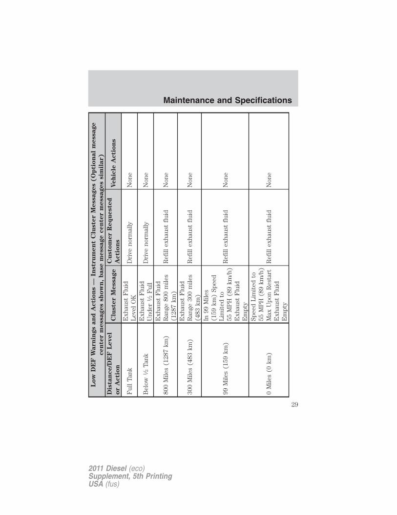
DEF warning messages and vehicle operations
WARNING: Diesel Exhaust Fluid (DEF) must be refilled whenlow or replaced when contaminated or the vehicle speed will be
speed limited to 55 mph (89 km/h) and then 50 mph (80 km/h). Inthese conditions, drive with caution and refill DEF immediately. If theDEF becomes empty or contaminated fluid is not replaced, the vehiclewill become limited to idle speed only once stopped. In theseconditions, be cautious where you stop the vehicle because you maynot be able to drive long distances and will not be able to maintainhighway speeds until DEF is refilled or replaced.
Your vehicle’s message center will display a series of messages regardingthe amount of DEF available. A systems check will display messagesindicating the amount of DEF available (OK or under 1⁄2 full) or willproduce a warning message that displays the mileage (kilometers)remaining as the fluid in the DEF tank nears empty. For moreinformation on warning messages, see the Message center section in theInstrument Cluster chapter of your Owner’s Guide.
As the DEF level nears empty, theDEF warning symbol will bedisplayed and chimes will soundwith the messages starting at300 miles (483 km) remainingbefore DEF is depleted. Thewarning symbol and messages willcontinue until the DEF tank isrefilled.
Continued driving without refilling will result in the following actions asrequired by the California Air Resources Board (CARB) and /or U.S.Environmental Protection Agency (EPA):
• Within a certain number of miles (kilometers) to empty, speed will belimited upon vehicle restart. Prior to this occurring a message willappear in the message center.
• Further vehicle operation without refilling your DEF tank will causethe engine to enter an idle-only condition. This will only occur uponvehicle refueling and will be indicated by a message in the messagecenter indicating required actions to resume normal operation. It isrequired to add a minimum of 0.5 gallons (1.9L) of DEF to the tank toexit the idle-only condition, but the vehicle will still be in the speedlimiting mode until the tank is refilled.
Maintenance and Specifications
27
2011 Diesel (eco)Supplement, 5th PrintingUSA (fus)

For either vehicle speed limiting or idle-only condition, normal vehicleoperation will resume when the DEF tank is refilled.
Note: When filling the DEF tank from empty, there may be a short delaybefore detecting the increased level of DEF. This must occur before fullpower is returned.
Maintenance and Specifications
28
2011 Diesel (eco)Supplement, 5th PrintingUSA (fus)
Lo
wD
EF
Warn
ings
an
dA
cti
on
s—
Instr
um
en
tC
luste
rM
essages
(O
pti
on
al
message
cen
ter
messages
sh
ow
n,
base
message
cen
ter
messages
sim
ilar)
Dis
tan
ce/D
EF
Level
or
Acti
on
Clu
ste
rM
essage
Cu
sto
mer
Req
ueste
d
Acti
on
sVeh
icle
Acti
on
s
Ful
lT
ank
Exh
aust
Flu
idL
evel
OK
Dri
veno
rmal
lyN
one
Bel
ow1⁄2
Tan
kE
xhau
stF
luid
Und
er1⁄2
Ful
lD
rive
norm
ally
Non
e
800
Mile
s(1
287
km)
Exh
aust
Flu
idR
ange
800
mile
s(1
287
km)
Ref
illex
haus
tfl
uid
Non
e
300
Mile
s(4
83km
)E
xhau
stF
luid
Ran
ge30
0m
iles
(483
km)
Ref
illex
haus
tfl
uid
Non
e
99M
iles
(159
km)
In99
Mile
s(1
59km
)Sp
eed
Lim
ited
to55
MP
H(8
9km
/h)
Exh
aust
Flu
idE
mpt
y
Ref
illex
haus
tfl
uid
Non
e
0M
iles
(0km
)
Spee
dL
imit
edto
55M
PH
(89
km/h
)M
axU
pon
Res
tart
Exh
aust
Flu
idE
mpt
y
Ref
illex
haus
tfl
uid
Non
e
Maintenance and Specifications
29
2011 Diesel (eco)Supplement, 5th PrintingUSA (fus)

Lo
wD
EF
Warn
ings
an
dA
cti
on
s—
Instr
um
en
tC
luste
rM
essages
(O
pti
on
al
message
cen
ter
messages
sh
ow
n,
base
message
cen
ter
messages
sim
ilar)
Dis
tan
ce/D
EF
Level
or
Acti
on
Clu
ste
rM
essage
Cu
sto
mer
Req
ueste
d
Acti
on
sVeh
icle
Acti
on
s
Res
tart
Spee
dL
imit
edTo
55M
PH
(89
km/h
)E
xhau
stF
luid
empt
y
Ref
illex
haus
tfl
uid
Spe
edis
limit
edto
55M
PH
.(8
9km
/h)
In20
0M
iles
(322
km)
afte
rve
hicl
ere
ache
s0
mile
(0km
)D
EF
rang
e
Spee
dL
imit
edto
50M
PH
(80
km/h
)E
xhau
stF
luid
Em
pty
Ref
illex
haus
tfl
uid
On
vehi
cle
rest
art,
spee
dis
limit
edto
50M
PH
(80
km/h
).(N
oac
tion
take
nun
til
vehi
cle
isre
fuel
ed)
Res
tart
Spee
dL
imit
edTo
50M
PH
(80
km/h
)E
xhau
stF
luid
Em
pty
Ref
illex
haus
tfl
uid
In30
0M
iles
(483
km)
afte
rve
hicl
ere
ache
s0
mile
(0km
)D
EF
rang
e
Eng
ine
Idle
dU
pon
Ref
uel
Exh
aust
Flu
idE
mpt
yR
efill
exha
ust
flui
dN
one
Die
sel
Tan
kF
ill
Eng
ine
Idle
d-Se
eO
wne
r’sM
anua
lE
xhau
stF
luid
Em
pty
Ref
illex
haus
tfl
uid
Eng
ine
limit
edto
idle
ON
LY(N
oac
tion
take
nun
til
vehi
cle
isre
fuel
ed)
Maintenance and Specifications
30
2011 Diesel (eco)Supplement, 5th PrintingUSA (fus)

Filling the DEF tankYour vehicle is equipped with a DEF tank with a blue-capped filler portlocated next to the diesel fuel fill inlet. The tank can be filled using anozzle at a DEF filling station (similar to fuel fill) or using a DEF bottlewith a spout. Motorcraft� DEF bottles are recommended as they aredesigned to be spill proof and will stop the flow of DEF when the tank isfull. Other aftermarket bottles can be used, but they should have a sealon the spout and an internal vent tube to achieve best fill performanceand prevent overfilling. Overfilling your DEF tank can cause damage tothe tank. For DEF capacity, see Maintenance product specificationsand capacities in this chapter.Note: Do not put DEF in the fuel tank. This can cause engine damagenot covered by your vehicle’s warranty.Note: Immediately wipe away any DEF that has spilled on paintedsurfaces with water and a damp cloth to prevent damage to the paint.You can purchase DEF at your authorized dealer, most highway truckstops or you can contact roadside assistance for help in finding a retailerthat sells DEF. See the Customer Assistance chapter in the Owner’sGuide for more information. In addition, there is a government websitelocator for DEF at the following web address that can be used to find thenearest location to purchase DEF: http://www.afdc.energy.gov/afdc/locator/def.
Use only DEF certified by theAmerican Petroleum Institute (API)such as Motorcraft� DEF orequivalent meeting Fordspecification WSS-M99C130-Aand/or ISO 22241. Look for APIcertification trademark shown here.Repairs resulting from the use ofnon-certified DEF products may not be covered by your vehicle’swarranty.Maintaining the purity of DEF is important to avoid malfunctions in theSCR system.If DEF is removed from the tank for repair work, etc., the same DEFmust not be used to refill the tank as its purity is no longer guaranteed.
WARNING: Make sure that DEF does not come into contactwith eyes, skin or clothing. Should DEF contact your eyes, flush
them with plenty of water and contact a physician. Clean affected skinwith soap and water. If DEF is swallowed, drink plenty of water andcontact a physician immediately.
Maintenance and Specifications
31
2011 Diesel (eco)Supplement, 5th PrintingUSA (fus)

WARNING: Refill DEF in a well-ventilated area. When openingthe cap on the DEF tank or bottle containing DEF, ammonia
vapors may escape. The vapors can be irritating to skin, eyes andmucous membranes. Inhaling ammonia vapors can cause burning to theeyes, throat and nose and cause coughing and watery eyes.
To fill the DEF tank, see your authorized dealer or do the following(before filling the DEF tank in cold climates, see Filling the DEF tankin cold climates later in this section):
• DEF bottle fill with spout:
The following procedure applies to Motorcraft� DEF or similar DEFbottles; for other brands or bottle types, refer to the instructions on thebottle label.
1. Remove the cap from the DEFcontainer. Remove the spout fromthe bottle and insert the straw endinto the bottle. Ensure that thearrow above the nut is aligned withthe bottle handle and the small tubeend extends into the far corner ofthe bottle. Twist the spout nut onthe container until it is tight.
2. Open the DEF filler port on thevehicle by turning the blue capcounterclockwise.
Maintenance and Specifications
32
2011 Diesel (eco)Supplement, 5th PrintingUSA (fus)

3. Lift and hold the DEF container,without tipping, and insert the spoutinto the DEF filler port until thesmall black seal on the spout iscompletely seated into the DEFfiller port.
4A. While filling, the fluid level inthe bottle will continually drop.
4B. When the DEF tank is full, thefluid level in the bottle will stopdropping, indicating the fluid hasstopped flowing.
Maintenance and Specifications
33
2011 Diesel (eco)Supplement, 5th PrintingUSA (fus)

5. Once the level in the DEF bottlehas stopped dropping, return thecontainer to the vertical positionslightly below the DEF filler portand let any DEF drain out of thespout. DO NOT try to continue toadd DEF to the tank by shaking orrepositioning the container toinduce flow. This may cause spillingand overfill the tank. Overfilling theDEF tank can cause damage to thetank.
6. Once the spout has drained, remove the spout from the DEF fillerport and install the blue cap on the DEF filler port.
7. Remove the spout from the DEF container and install the cap back onthe bottle.
8. If the container is empty, discard the empty container and spout, orrecycle if possible. If there is some DEF left in the container, retain itand the spout for later use. Store the spout to ensure it is kept clean.
9. Wipe away any DEF that has spilled on painted surfaces with waterand a damp cloth.
• DEF filling station nozzle fill:
Filling the DEF tank using a nozzle is similar to a normal fuel fill. Thenozzle will shut off automatically when the tank is full. Do not continueto fill the tank as this may cause spilling and overfill the tank which cancause damage.
Note: Some filling station nozzles may prevent filling of your DEF tankdue to a magnetic mechanism in the nozzle. This is not a problem withyour vehicle. To refill your tank either locate another filling station oruse a bottle to refill the tank.
Filling the DEF tank in cold climatesDEF will freeze below 12°F (-11°C); however, your vehicle is equippedwith an automatic preheating system which allows the DEF system tooperate below 12°F (-11°C). When the vehicle is not in operation for anextended period of time with temperatures at or below 12°F (-11°C), theDEF tank could freeze. If the tank is OVERFILLED and freezes, it couldbe damaged, therefore DO NOT OVERFILL.
Maintenance and Specifications
34
2011 Diesel (eco)Supplement, 5th PrintingUSA (fus)

To prevent overfilling of the DEF tank when filling with a bottle, Fordrecommends using Motorcraft� DEF. Additionally, if the message centerindicates EXHAUST FLUID UNDER 1/2 FULL, you should only add aMAXIMUM of 2 gallons (6.7L) of DEF to the tank to prevent freezedamage due to overfilling. If the message center indicates EXHAUSTFLUID LEVEL OK, do not add DEF.Contaminated DEFSCR systems are sensitive tocontamination of the DEF. USEONLY API or ISO 22241 CERTIFIEDDIESEL EXHAUST FLUID. If thesystem becomes contaminated, theDEF light will illuminate andcontaminated exhaust fluidmessages will appear in the messagecenter.Continued driving without replacing DEF will result in the followingactions as required by the California Air Resources Board (CARB) and/or U.S. Environmental Protection Agency (EPA):• Within a certain number of miles (kilometers) to empty, speed will be
limited upon restart. Prior to this occurring a message will appear inthe message center.
• Further vehicle operation without replacing contaminated DEF willcause the engine to enter an idle-only condition. This will only occurupon vehicle refueling and will be indicated by a message in themessage center indicating required actions to resume normaloperation.
For either vehicle speed limiting or idle-only condition, normal vehicleoperation will resume when the contaminated system is repaired. Toservice a contaminated SCR system, see your authorized dealer.
DEF guidelines and information
• Use only DEF that carries the trademark: American PetroleumInstitute (API) certified DEF or ISO 22241.
• Do not put DEF in the diesel fuel tank.• Do not overfill the DEF tank.• Do not re-use the DEF container or nozzle once it is emptied.• Avoid spilling DEF on painted surfaces, carpeting or plastic
components. Immediately wipe away any DEF that has spilled with adamp cloth and water. If it has already crystallized, use warm waterand a sponge.
Maintenance and Specifications
35
2011 Diesel (eco)Supplement, 5th PrintingUSA (fus)

• Store DEF out of direct sunlight and in temperatures between 23°F(-5°C) — 68°F (20°C).
• DEF will freeze below 12°F (-11°C).
• Do not store DEF bottle in vehicle. If it leaks it could cause damage tointerior components or release an ammonia odor inside the vehicle.
• DEF is non-flammable, non-toxic, colorless and water-soluble liquid.
• Do not dilute DEF with water or any other liquid.
• An ammonia odor may be smelled when the cap is removed or duringrefill. Refill DEF in a well ventilated area.
Typical Diesel Exhaust Fluid (DEF) Usage
The charts below illustrate approximate DEF usage for the givendistances traveled under various driving conditions and when using thePTO. Your usage may vary depending on: driving style, trailer towing,loaded vehicle weight, weather, idle time, PTO usage, etc.
Pick-up (3.31 axle ratio)
Drivingstyle
Trailer towing /aggressive or city
drivingNormal driving
Steady highwaydriving
DEFusage
4100 miles(6598 km) –7100 miles(11426 km)
7100 miles(11426 km) –
9600 miles(15450 km)
9600 miles(15450 km) –10000 miles
(16093 km) +
Pick-up (3.55 axle ratio)
Drivingstyle
Trailer towing /aggressive or city
drivingNormal driving
Steady highwaydriving
DEFusage
2800 miles(4506 km) –5800 miles(9334 km)
5800 miles(9334 km) –8100 miles(13036 km)
8100 miles(13036 km) –
9700 miles(15611 km)
Maintenance and Specifications
36
2011 Diesel (eco)Supplement, 5th PrintingUSA (fus)

Pick-up (3.73 axle ratio)
Drivingstyle
Trailer towing /aggressive or city
drivingNormal driving
Steady highwaydriving
DEFusage
2050 miles(3299 km) –5050 miles(8127 km)
5050 miles(8127 km) –7300 miles(11748 km)
7300 miles(11748 km) –
8900 miles(14323 km)
Pick-up (4.30 axle ratio)
Drivingstyle
Trailer towing /aggressive or city
drivingNormal driving
Steady highwaydriving
DEFusage
1100 miles(1770 km) –4100 miles(6598 km)
4100 miles(6598 km) –6300 miles(10139 km)
6300 miles(10139 km) –
7900 miles(12714 km)
Chassis cab (non–PTO)
Drivingstyle
Trailer towing /aggressive or city
drivingNormal driving
Steady highwaydriving
DEFusage
1700 miles(2736 km) –4700 miles(7564 km)
4700 miles(7564 km) –7800 miles(12553 km)
7800 miles(12553 km) –
9300 miles(14967 km)
Chassis cab (with PTO)PTOusage
< - - - Cont. PTO usage — Min. PTO usage - - - >
DEFusage
0 miles (0 km) — 7800 miles (12553 km)
FUEL FILTER/WATER SEPARATOR
Diesel Fuel Conditioner Module (DFCM)The vehicle is equipped with a diesel fuel conditioning module (DFCM)located on the frame-rail under the driver-side floorboard near thetransmission
Maintenance and Specifications
37
2011 Diesel (eco)Supplement, 5th PrintingUSA (fus)

Water should be drained from themodule assembly whenever thewarning light comes on and themessage center directs you to drainthe water separator. This will occur when approximately 0.32 pints (150ml) of water accumulates in the module. If water level is allowed toexceed this level, the water may be passed through to the engine andmay cause fuel injection equipment damage.
Draining the DFCM1. Stop the vehicle and shut off the engine.
WARNING: The vehicle must be stopped with the engine offwhen draining the DFCM. Fuel may ignite if the separator is
drained while the engine is running or vehicle is moving.
Note: Air will enter into the fuel system if the DFCM is drained whilethe system is running. The engine will not operate properly if air entersthe system.
2. Locate the DFCM and place an appropriate container under the drainport (see illustration).
3. Rotate the drain counterclockwiseuntil the O-ring is visible. Allow theDFCM to drain for approximately25 seconds or until clean fuel isobserved. Rotate the drain clockwiseto tighten it.
4. Make sure that the drain valve is fully tightened, then remove thecontainer from under the vehicle.
Note: A loose drain valve can allow air to enter the fuel system andcause drivetrain issues. The engine will not operate properly. be surethat the drain valve is fully tightened.
5. Restart the engine. The WATER IN FUEL DRAIN FILTER orWATER IN FUEL DRAIN FILTER SEE MANUAL message and lightshould not be illuminated. If they continues to illuminate, have the fuelsystem checked and repaired.
Maintenance and Specifications
38
2011 Diesel (eco)Supplement, 5th PrintingUSA (fus)

LOW FUEL PRESSURE MESSAGEThe engine is equipped with a low fuel pressure detection system. If themessage center displays: LOW FUEL PRESSURE the followingexplains why and what to do:• Cold start or cold operation (below 32°F (0°C): If this message
appears during a cold start or during cold operation up to 10 minutesafter the initial cold start, monitor the message center. If it disappearsand does not re-appear after the engine has fully warmed up, the lowfuel pressure message is most likely caused by waxed or gelled fuel.Do not use alcohol based additives to correct fuel gelling. This mayresult in damage to the fuel injectors/systems. Use an anti-gel additiveas listed in Maintenance product specifications and capacitiessection in this chapter. The customer warranty may be void from usingadditives that do not meet or exceed Ford specifications.If the low fuel pressure message persistently appears after re-fuelingduring the cold start and cold operation conditions defined previouslyand then disappear when the engine has fully warmed up, considerdifferent fuel sources.
• Low fuel operation: If the message appears when the vehicle is warmand during low fuel tank level operation, i.e. the tank level is at orvery near empty, refuel the vehicle and operate the vehicle. If themessage reappears after fueling, see below. If the message does notcome back, the low fuel pressure condition was due to low fuel levelsin the fuel tank.
• Normal operation: If the message appears during normal operationwhen the vehicle / engine is fully warm, and fuel level is not low, thefuel filters must be changed regardless of the maintenance scheduleinterval.
• If replacement of the fuel filter does not remedy the low fuel pressuremessage during normal operation as defined above, take the vehicle toyour authorized dealer.
CHANGING THE ENGINE-MOUNTED AND DFCM FUEL FILTERSYour vehicle is equipped with two fuel filters; one is mounted on top ofthe driver’s side of the engine and the second filter, inside the DFCM, ismounted on the frame rail under the driver-side floorboard near thetransmission. Both filters should be replaced at the same time. Regularfuel filter changes are an important part of engine maintenance; failing tokeep with the scheduled maintenance could lead to engine performanceissues and/or fuel injection system damage. Refer to the scheduledmaintenance information of this supplement for more information.
Maintenance and Specifications
39
2011 Diesel (eco)Supplement, 5th PrintingUSA (fus)

Refer to Motorcraft part numbers later in this chapter for the fuel filterreplacement part number. This part number includes filters and seals forboth the engine-mounted and frame-mounted filters.
Removal - DFCM filterThe DFCM filter is located in the lower portion of the DFCM housing.
1. Drain the DFCM. See Fuel filter/water separator earlier in thischapter.
To install the new DFCM filter, see Installation – DFCM filter later inthis section.
2. Remove the lower portion of theDFCM housing (filter bowl) byturning it counterclockwise using a32 mm socket.Note: Depending on the amountseal swelling, removal of the filterbowl may be noisy and require someeffort. Replace the seal prior toreinstalling the filter/bowl toimprove assembly.
3. Remove and discard the old fuel filter element.
4. Carefully clean the mating surfaces using a lint-free rag.
Installation – DFCM filter1. Install the new filter into the filter bowl tabs and replace the seal onthe DFCM header (top portion of DFCM). Refer to Motorcraft partnumbers later in this chapter for the fuel filter kit part number.
2. Reinstall the lower portion of the housing by slowly turning itclockwise onto DFCM housing, allowing fuel to soak into the fuel filterelement. Tighten the lower housing until it contacts the mechanical stop.
Note: The engine will not run properly if the DFCM fuel filter is notinstalled in the housing.
The system will need to be purged of air after removal/changing of thefilter. See Purging air from the fuel system after DFCM and enginemounted fuel filter replacement following.
Maintenance and Specifications
40
2011 Diesel (eco)Supplement, 5th PrintingUSA (fus)

Removal - Engine-mounted fuel filterThe engine-mounted fuel filter is a plastic disposable cartridge. Toremove it, do the following:
1. Disconnect both fuel lines bysqueezing the connector tabs andpulling the lines straight off.Note: Although the fuel system isnot fully pressurized when thevehicle is off, some residualpressure may remain in the fuelsystem since it can take some timefor the pressure to completely bleedoff. Therefore, it is recommended toplace a shop rag below the filterconnectors to absorb the small amount of fuel that will drain.
2. Loosen the bracket bolt.
3. Rotate the filter counterclockwise until it unlocks from the bracket.4. Pull the filter straight out from the bracket and discard the filter.Installation – Engine-mounted fuel filter1. Install the new filter into the filterbracket. The filter has two lockingtabs: one on the bottom and one onthe side approximately 180° fromthe bracket bolt. Line this tab upwith the slot and the bottom willfollow. Turn the filter clockwise tolock it in place.
2. Tighten the bracket bolt until the filter is snug in the bracket.
Maintenance and Specifications
41
2011 Diesel (eco)Supplement, 5th PrintingUSA (fus)

3. Reconnect both fuel lines.
Using a fuel which has more than average impurities may requirethe fuel filter to be replaced more frequently than the serviceinterval specifies.
The system will need to be purged of air after removal/changing of thefilter. See Purging air from the fuel system after DFCM andengine-mounted fuel filter replacement following.
Purging air from the fuel system after DFCM and engine mountedfuel filter replacement
Turn the ignition key to on for 30 seconds, then turn it to off. Do this atotal of six times in a row to purge any trapped air from the fuel system.
After filter service, a no start or rough running engine may indicate thatair is entering the system through the filter bowl seal or drain. Make surethe drain is tight.
ENGINE OIL
Checking the engine oil level
Because it is normal to add some oil between oil changes, check yourengine oil level each time you stop for fuel. To check the engine oil levelconsistently and accurately, the following procedure is recommended:
1. Have engine at normal operating temperature (at least into theNORMAL range on the engine coolant temperature gauge).
2. Park the vehicle on a level surface, then turn off the engine and openthe hood.
3. Allow at least 20 minutes after engine shutdown to ensure that theoil contained in the upper parts of the engine has returned to the oilpan.
4. Protecting yourself from engine heat, pull out the dipstick, wipe itclean and reinsert fully.
5. Read oil level on both sides of dipstick and use highest level (reading)for the actual engine oil level.
Maintenance and Specifications
42
2011 Diesel (eco)Supplement, 5th PrintingUSA (fus)

6. it is best to maintain the oil levelwithin the crosshatch area on thedipstick by adding oil as required.The lower hole is the minimum oillevel and the upper hole is themaximum oil level. Do not overfill.The distance from the lower hole(oil minimum) to the uppercrosshatch area on the dipstick represents 1.0 quart (.95L).
Engine oil specifications
To help achieve acceptable engine performance and durability, it isimportant that only engine oils of good quality are used in your dieselengine and it is changed at the recommended interval. For normal orsevere service, use Motorcraft� oil or an equivalent oil conforming toFord specifications as listed in the Maintenance product specificationsand capacities section in this chapter or API service categories CJ-4 orCJ-4/SM. It is important to use these oils because they are compatiblewith the emission control equipment of your vehicle to meet the morestringent emission standards.
The use of correct oil viscosities for diesel engines is important forsatisfactory operation. Determine which oil viscosity best suits thetemperature range you expect to encounter for the next service intervalfrom the following SAE viscosity grade chart.
Maintenance and Specifications
43
2011 Diesel (eco)Supplement, 5th PrintingUSA (fus)

1For severe duty usage, use SAE 5W-40 API CJ-4.2For biodiesel (grades B6-B20) usage, use SAE 5W-40 or SAE15W-40 API CJ-4.
An engine block heater is recommended at temperatures below –10°F(–23°C).
A symbol has been developed by theAmerican Petroleum Institute (API)to help you select the proper engineoil. It will be included on the oilcontainer you purchase. The topsection of the symbol shows the oilperformance by the API designation. This should match the owner guiderecommendation. The center section will show the SAE viscosity grade
Changing the engine oil and oil filterYour vehicle is equipped with an Intelligent Oil Life Monitor™ thatcalculates the proper oil change service interval. When the messagecenter indicates: OIL CHANGE REQUIRED, change the engine oil andoil filter. See the Message center section of the Instrument Clusterchapter for more information.
Refer to Motorcraft part numbers later in this chapter for the engine oilfilter part number. This filter protects your engine by filtering harmful,abrasive or sludge particles and particles significantly smaller than mostavailable “will-fit” filters.
-20 -10 0 10 20 30 40
3832272116104-1-7-12-18-23-29
50 60 70 80 90 100
SAE VISCOSITY GRADES
EXPECTED TEMPERATURE RANGE
F˚
C˚
5W-401,2
0W-30 / 0W-40
15W-402
10W-30 (Normal Usage)
AP
I S
ERVICE CJ-4/SMSAE10W-30
Maintenance and Specifications
44
2011 Diesel (eco)Supplement, 5th PrintingUSA (fus)

To change the engine oil and oil filter:
1. Unscrew the oil filter and oil pan drain plug and wait for the oil todrain.Note: The oil pan drain plug only requires 1/4 turn to removal/install. A3/8 inch socket drive may be used to assist with removal/installation, butbe careful not to over-tighten the plug during installation.2. Replace the filter.3. Reinstall the oil pan drain plug.4. Refill the engine with new oil. For the proper capacity, seeMaintenance product specifications and capacities in this chapter.5. Reset the Intelligent Oil Life Monitor™. See Message center in theInstrument Cluster chapter for more information.
WARNING: Do not handle a hot oil filter with bare hands.
WARNING: Continuous contact with used motor oil has causedcancer in laboratory mice. Protect your skin by washing with
soap and water.
Engine lubrication for severe service operationThe following conditions define severe operation for which engineoperation with SAE 5W-40 API CJ-4 is recommended. Oil and oil filterchange intervals will be determined by the Intelligent Oil Life Monitor™as noted previously.• frequent or extended idling (over 10 minutes per hour of normal
driving)
• low-speed operation/stationary use
• if vehicle is operated in sustained ambient temperatures below -10°F(-23°C) or above 100°F (38°C)
• frequent low-speed operation, consistent heavy traffic less than25 mph (40 km/h)
• operating in severe dust conditions
• operating the vehicle off road
• towing a trailer over 1,000 miles (1,600 km)
• sustained, high-speed driving at Gross Vehicle Weight Rating(maximum loaded weight for vehicle operation)
Maintenance and Specifications
45
2011 Diesel (eco)Supplement, 5th PrintingUSA (fus)

• use of fuels with sulfur content other than ultra-low sulfur diesel(ULSD)
• use of high-sulfur diesel fuel
ENGINE AND SECONDARY COOLING SYSTEM COOLANTChecking engine coolant
The concentration (freeze point protection), additive strength (corrosioninhibitor), and level of coolant should be checked at the mileage intervalslisted in the scheduled maintenance information. The coolantconcentration should be maintained at 50/50 coolant and water, whichequates to a freeze point of -36°C (-34°F). Coolant concentration testingis possible with a hydrometer or antifreeze tester (such as the RotundaBattery and Antifreeze Tester, 0014–R1060). The level of coolant shouldbe maintained within the COLD FILL RANGE in the coolant reservoirs. Ifthe level falls below, add coolant per the instructions in the Addingcoolant section.
Your vehicle was factory-filled with a 50/50 coolant and waterconcentration. If the concentration of coolant falls below 40% or above60%, the engine parts could become damaged or not work properly. A50/50 mixture of coolant and water provides the following:
• freeze protection down to -36°C (-34°F).
• boiling protection up to 129°C (265°F).
• protection against rust and other forms of corrosion.
• an accurate temperature readout from the engine coolantgauge.
When the engine is cold, check the level of coolant in the reservoirs. SeeIdentifying components in the engine compartment for the location ofthe engine and secondary cooling system reservoirs.
• The coolant should be within the COLD FILL RANGE in the coolantreservoirs.
• Refer to the scheduled maintenance information for service intervalschedules.
• Be sure to read and understand Precautions when servicing yourvehicle in your Owner’s Guide.
If the coolant has not been checked at the recommended interval, theengine or secondary coolant reservoir may become low or empty. Ifeither reservoir is low or empty, add coolant to the reservoir(s). Refer toEngine and secondary cooling system refill procedure in this chapter.
Maintenance and Specifications
46
2011 Diesel (eco)Supplement, 5th PrintingUSA (fus)

Note: Automotive fluids are not interchangeable; do not use enginecoolant or windshield washer fluid outside of its specified function andvehicle location.
Adding coolantWhen adding coolant, make sure it is a 50/50 mixture of coolant anddistilled water. Add the mixture to the coolant reservoir(s), when theengine is cool, until the appropriate fill level is obtained.If you have to add more than 1.0 quart (1.0 liter) of coolant per month,have your dealer check the cooling system. Your cooling system mayhave a leak. Operating an engine with a low level of coolant can result inengine overheating and possible engine damage.Note: If coolant is added to bring the level within the COLD FILLRANGE when the engine is not cold, the system will remain underfilled.
WARNING: Do not add coolant when the engine is hot. Steamand scalding liquids released from a hot cooling system can burn
you badly. Also, you can be burned if you spill coolant on hot engineparts.
WARNING: Do not put coolant in the windshield washer fluidcontainer. If sprayed on the windshield, coolant could make it
difficult to see through the windshield.
• Do not mix coolants. Add the coolant type originally equippedin your vehicle. Refer to Maintenance product specifications andcapacities in this chapter for the proper coolant type.
Note: Do not use stop leak pellets or cooling system sealants/additivesas they can cause damage to the engine cooling and/or heating systems.This damage would not be covered under your vehicle’s warranty.
• A large amount of water without engine coolant may be added to theengine cooling system only, in case of emergency, to reach a vehicleservice location. Avoid this procedure if delivery to the service locationrequires heavy engine loads. In this instance, the cooling system(s)must be drained, chemically cleaned with Motorcraft� Engine CoolingSystem Iron Cleaner, and refilled with a 50/50 mixture of coolant anddistilled water as soon as possible. Water alone (without coolant) cancause damage from corrosion, overheating or freezing. DO NOT usethis method for the secondary cooling system. The secondary coolingsystem operates close to ambient temperature, and is susceptible tofreezing in any subfreezing environment, in the absence of coolant.
Maintenance and Specifications
47
2011 Diesel (eco)Supplement, 5th PrintingUSA (fus)

• Do not use alcohol, methanol or brine or any engine coolantsmixed with alcohol or methanol antifreeze (coolant). Alcoholand other liquids can cause engine damage from overheating orfreezing.
• Do not mix with recycled coolant unless from a Ford-approvedrecycling process (see Use of recycled engine coolant section).
WARNING: To reduce the risk of personal injury, make sure theengine is cool before unscrewing the coolant pressure relief cap.
The cooling system(s) are under pressure; steam and hot liquid cancome out forcefully when the cap is loosened slightly.
Add the proper mixture of coolant and distilled water to the coolingsystem(s) by following these steps:
1. Before you remove the cap, turn the engine off and let it cool.
2. When the engine is cool, wrap a thick cloth around the cap. Slowlyturn cap counterclockwise until pressure begins to release.
3. Step back while the pressure releases.
4. When you are sure that all the pressure has been released, use thecloth to turn it counterclockwise and remove the cap.
Engine and secondary cooling system refill procedureThe following procedure should be used when refilling the engine orsecondary cooling systems after it has been drained or become extremelylow.
1. Remove the pressure relief cap from the engine or secondary coolantreservoir as previously outlined.
2. Slowly add a 50/50 mixture of coolant and distilled water to thecoolant reservoir until the coolant level is within the COLD FILL RANGEas listed on the reservoir.
3. Reinstall the pressure relief cap.
4. Start and run the engine at 2,000 rpm for 2 minutes.
5. Shut engine off, and remove the pressure relief cap as previouslyoutlined.
6. If required, add a 50/50 mixture of coolant and distilled water to thecoolant reservoir until the coolant level is within the COLD FILL RANGEas listed on the reservoir.
Maintenance and Specifications
48
2011 Diesel (eco)Supplement, 5th PrintingUSA (fus)

7. Engine cooling system: Repeat Step 3 until the coolant level hasstabilized (is no longer dropping after each step) AND the upper radiatorhose at the radiator is warm to the touch (indicating that the enginethermostat is open and coolant is flowing through the radiator).
Secondary cooling system: Repeat Step 3 until the coolant level hasstabilized (is no longer dropping after each step) AND the lowerpassenger side of the secondary radiator is warm to the touch(indicating secondary thermostat is open and coolant is flowingthrough the entire system).
8. Reinstall the pressure relief cap. Shut the engine off and let it cool.
9. Check the coolant level in the reservoir before you drive your vehiclethe next few times (with the engine cool).
10. If necessary, add a 50/50 mixture of coolant and distilled water to thecoolant reservoir until the coolant level is within the COLD FILL RANGEas listed on the reservoir. After any coolant has been added, check thecoolant concentration. See Engine and secondary cooling systemcoolant earlier. If the concentration is not 50/50 (protection to–34°F/–36°C), drain some coolant and adjust the concentration. It maytake several drains and additions to obtain a 50/50 coolant concentration.
Whenever coolant has been added, the coolant level in the coolantreservoir should be checked the next few times you drive the vehicle. Ifnecessary, add enough 50/50 concentration of coolant and distilled waterto bring the liquid level to the proper level.
Coolant refill capacityTo find out how much fluid your vehicle’s cooling system can hold, referto Maintenance product specifications and capacities in this chapter.
Coolant additivesAt specific mileage intervals of 15,000 miles (24,000 km), as listed in thescheduled maintenance information chapter, the coolant additiveshould be checked. The optional message center, if equipped, will alsodisplay the message CHECK COOLANT ADDITIVE at this time. Thepurpose of checking is to verify the correct concentration (freeze pointprotection) and additive strength (corrosion inhibitor) levels of thecoolant for maximum engine performance and protection. Threeproducts are available for ensuring the life and health of the coolant: twotest kits and a coolant inhibitor additive:
• Rotunda 328-00007 (Matthew’s Water CoolCheck) – Evaluates waterquality (hardness, chloride, and pH) for 50/50 mixture of coolant and
Maintenance and Specifications
49
2011 Diesel (eco)Supplement, 5th PrintingUSA (fus)

distilled water. Use distilled water. If distilled water is unavailable,water meeting the requirements of Rotunda 328-00007, is sufficientfor vehicle use. Using water that fails to meet the requirements canlead to coolant passage scaling and degrade the engine’s durability andperformance.
• Rotunda 328-00008 (Antifreeze Coolant ELC Contamination Kit) –Evaluates the coolant concentration (freeze point protection) andadditive strength (corrosion inhibitor) for overall coolant health. Notethat the first step is to verify that the vehicle’s coolant concentrationis in the window of 40 – 60%. If the concentration falls outside of thatwindow, the evaluation of the corrosion inhibitor strength will not bevalid. If the report results in a pass the cooling system does not showexcessive contamination. No action is required. If the report results asinsufficient, the corrosion inhibitor (additive) strength of the coolantis too low. Add entire contents of one bottle of Motorcraft� SpecialtyOrange Engine Coolant Revitalizer to the coolant reservoir. Thecoolant can be recharged with this additive up to two times before thecoolant must be changed-out. When exchanging the full coolantvolume, the system must be flushed and refilled with distilled waterand coolant concentrate (Motorcraft� Specialty Orange EngineCoolant).
• Motorcraft� Specialty Orange Engine Coolant Revitalizer – Additive toboost the corrosion inhibitor level based upon the test results of theAntifreeze Coolant ELC Contamination Kit. The revitalizer may beadded two times over the life of the coolant. If additional dosages arerequired, the cooling system must be flushed and refilled with distilledwater and coolant concentrate (Motorcraft� Specialty OrangeCoolant).
Refer to Maintenance product specifications and capacities in thischapter for the proper coolant and additive specifications.
Coolant changeAt specific mileage intervals, as listed in the scheduled maintenanceinformation, the coolant should be changed. The optional messagecenter, if equipped, will also display the message COOLANT CHANGEREQUIRED at this time.
Refer to Maintenance product specifications and capacities in thischapter for the proper coolant.
Maintenance and Specifications
50
2011 Diesel (eco)Supplement, 5th PrintingUSA (fus)

AIR FILTER RESTRICTION GAUGE AND AIR FILTERREPLACEMENTAir filter restriction gauge:
The restriction gauge, located onthe upper housing of the air filterassembly, measures the vacuuminside the air filter. The more the airfilter is restricted (dirty, clogged),the higher the vacuum reading
Check the air filter restriction gaugewhenever the hood is raised toperform general engine maintenanceat least every 7,500 miles (12,000 km). If the vehicle is operated inextremely dusty conditions, check and reset the gauge at least every500 miles (800 km), or two weeks, whichever comes first.
Change the air filter when the gauge reads near the “change filter” lineand the chamber is filled with yellow. Engine performance and fueleconomy are adversely affected when the maximum restriction isreached.
Blowing-out the air filter element with compressed air is notrecommended as the compressed air may damage the filter paper.
Note: It is not possible to determine the level of filter clogging by visualappearance alone. A filter which appears to be dirty may actually haveseveral thousand miles (kilometers) of life remaining.
Use the underhood air filter restriction gauge to determine whenthe air filter element needs to be changed.
Maintenance and Specifications
51
2011 Diesel (eco)Supplement, 5th PrintingUSA (fus)

After installation of the new filterelement, reset the gauge by pressingthe reset button on top of thegauge.
Note: Vehicle operation in heavysnowfall or extreme rain conditionsmay feed excessive amounts ofsnow/water into the air intakesystem. This could plug/soak the airfilter with snow and may cause theengine to lose power and possiblyshut down.
The following actions are recommend after operating the vehicle up to200 miles (320 km) in heavy snowfall or extreme rain:
• Snow: At the earliest opportunity, open the hood and clear all thesnow and ice from the air filter housing inlet (do NOT remove thefoam filter) and reset the air filter restriction gauge.
• Extreme rain: The air filter will dry after about 15–30 minutes athighway speeds. At the earliest opportunity, open the hood and resetthe air filter restriction gauge.
Air filter replacement:
When replacing the air filter element, use the Motorcraft� air filterelement listed in Motorcraft part numbers later in this chapter.
WARNING: To reduce the risk of vehicle damage and/orpersonal burn injuries do not start your engine with the air filter
removed and do not remove it while the engine is running.
Maintenance and Specifications
52
2011 Diesel (eco)Supplement, 5th PrintingUSA (fus)

Failure to use the correct air filter element may result in severeengine damage.
1. Locate the mass air flow sensorelectrical connector on the air inlettube. This connector will need to beunplugged.
Unlock the locking clip on theconnector, then squeeze and pullthe connector off of the air inlettube.
2. Release the four clamps thatsecure the cover to the air filterhousing. Push the air filter coverforward (away from you) and upslightly to release it.
3. Remove the air filter element from the air filter housing.
Maintenance and Specifications
53
2011 Diesel (eco)Supplement, 5th PrintingUSA (fus)

4. Remove and install a new foamfilter if needed according to theservice interval indicated in thescheduled maintenanceinformation in this guide. If thefoam filter is not being replaced, besure the existing foam filter is inplace.
5. Install a new air filter element. besure that the groove seal on thepleated paper filter traps both sidesof the vertical partition of the airbox.
6. Replace the air filter housingcover and secure the clamps. Becareful not to crimp the filterelement edges between the air filterhousing and cover and ensure thatthe tabs on the edge are properlyaligned into the slots.
7. Reconnect the mass air flow sensor electrical connector to the inlettube. Make sure the locking tab on the connector is in the “locked”position.
Maintenance and Specifications
54
2011 Diesel (eco)Supplement, 5th PrintingUSA (fus)

DIESEL EXHAUST SYSTEM: OXIDATION CATALYST/DIESELPARTICULATE FILTER SYSTEMYour vehicle is equipped with a diesel particulate filter (DPF). The DPFis an inline filter in the exhaust system which reduces carbon emissionsby trapping exhaust particles before they reach the tailpipe. The DPFlooks similar to a traditional exhaust catalyst, except larger, and is partof the exhaust system under the vehicle. The DPF is coupled to a dieseloxidation catalyst, that reduces the amount of harmful exhaust emittedfrom the tailpipe. As soot gathers in the system it begins to restrict thefilter. The soot gathered inside the filter needs to be periodically cleaned.The soot can be cleaned in two different ways; passive regeneration andactive regeneration. Both methods occur automatically and require noactions from the driver/operator. During either one of these regenerationmethods you may notice an increase/change in exhaust noise/tone. Atcertain times, the message center will display various messages relatedto the DPF. See Message center in the Instrument Cluster chapter inthe Owner Guide for more information.
Passive regenerationIn passive regeneration, the exhaust constituents / temperature are at anappropriate level where some soot can be reduced or oxidized (burned)thus cleaning the filter. This method occurs naturally as a result ofnormal engine operating conditions (at varying levels due to drivepatterns).
Active regenerationOnce the DPF is full of exhaust particles, the engine control module willcommand the exhaust system to clean the DPF through a process calledactive regeneration. Active regeneration requires the engine computer toraise the exhaust temperature to eliminate the particles. During cleaning,the particles are converted to harmless gasses, and the DPF will then beclean and ready to continue trapping exhaust particles.
The regeneration process operates more efficiently when the vehicle issafely operated at least 30 mph (48 km/h) with a steady pedal forapproximately 20 minutes to complete the process. The frequency andduration of regeneration will fluctuate as both are determined by howyou drive your vehicle, outside air temperature, and altitude. For mostdriving, regeneration frequency will vary from 100 - 500 miles (161 -805 km) between occurrences and each occurrence will last from 9 -20 minutes. The duration of regeneration is usually reduced if a constantspeed above 30 mph (48 km/h) is maintained.
Maintenance and Specifications
55
2011 Diesel (eco)Supplement, 5th PrintingUSA (fus)

When the engine control module detects that the DPF is nearly full ofparticulates and that the vehicle is not being operated in a manner toallow effective automatic cleaning, the message center will displayDRIVE TO CLEAN EXHAUST FILTER guiding the vehicle operator todrive in order to clean the DPF. If the vehicle is operated in a manner toallow effective automatic cleaning, the message center will displayCLEANING EXHAUST FILTER, which is the normal regenerationprocess. See Message center in the Instrument Cluster chapter of theOwner Guide for more information.
If the operator is not able to drive in manner that allows effectiveautomatic cleaning (active regeneration) or the operator instead wishesto perform regeneration of the DPF (cleaning) while at idle (stationary),then OCR (operator commanded regeneration) will need to beperformed. See Operator commanded regeneration (OCR) following.
Note: Do not disregard the DRIVE TO CLEAN EXHAUST FILTER
maintenance message for extended periods of time. Failure to performactive or operator commanded regeneration (OCR) (if equipped) wheninstructed may result in a clogged DPF. If your DPF fills beyond whatcan be safely regenerated, active regeneration and OCR will be disabled.This could cause irreversible damage to the DPF, requiring service andpossible replacement that may not be covered by your warranty.
Operator commanded regeneration (OCR) (if equipped)
If your vehicle is operated with significant stationary operation, passiveand active regeneration may not sufficiently clean the DPF system. OCRallows you to manually start regeneration of the diesel particulate filter(DPF) at idle (while stationary) to clean the DPF. If you are not surewhether your vehicle is equipped with this feature, contact yourauthorized dealer.
When to perform OCR
Use the OCR feature when the DRIVE TO CLEAN EXHAUST FILTER
message appears in the message center and:
• the operator is not able to drive in manner that allows effectiveautomatic cleaning (active regeneration),
• or the operator instead wishes to manually start regeneration(cleaning) of the DPF while the vehicle is idle (stationary).
Maintenance and Specifications
56
2011 Diesel (eco)Supplement, 5th PrintingUSA (fus)

OCR precautions and safe exhaust position
WARNING: Failure to comply with the following instructions foroperator commanded regeneration (OCR) may result in fire,
serious injury, death and/or property damage.
Before you start OCR, observe/do the following:• Place the vehicle in P (Park) with the parking brake set on stable,
level ground.• The vehicle must not be parked in a structure.• The vehicle must be away from any obstructions within 10 - 15 feet of
vehicle,• and must be away from materials that can easily combust or melt such
as: paper, leaves, petroleum products, fuels, plastics and other dryorganic material, such as grass.
• Make sure there is a minimum of 1/8 tank of fuel.• Make sure all fluids are at proper levels.Make sure that the louvers (holes) located at the tip of the exhaust arealso clear of any obstructions as they are used to introduce fresh air intothe tailpipe to cool the exhaust gas as it leaves. See Exhaust under theCleaning chapter for more information.
How to start operator commanded regeneration (OCR)
WARNING: Stay clear of exhaust tip during regeneration. You orothers can be burned.
Note: OCR will not be allowed to operate if the service engine soonlight is illuminated
Note: During the use of OCR, you may observe a light amount of whitesmoke. This is normal.1. Start with the vehicle engine fully warmed.2. Press the Info button on the steering wheel until the message centerreads EXHAUST FILTER XXX% FULL.
3. If the DPF needs cleaning and the vehicle is warmed up, a messagerequesting permission to initiate filter cleaning is displayed EXH XXX%FULL CLEAN Y/N. Answering yes to this prompt and then followingprompts will initiate OCR. Be sure to understand each prompt. If you arenot sure what is being asked by each prompt, contact your authorizeddealer.
Maintenance and Specifications
57
2011 Diesel (eco)Supplement, 5th PrintingUSA (fus)

4. Once OCR starts, the engine’s rpm will rise to approximately 2,000 -2,400 rpm and the cooling fan will increase speed; you will hear a changein audible sound due to the fan and engine speed increase.
It is not necessary to open the hood on the engine compartment. OnceOCR is complete, the engine rpm and fan will return to normal idling.The exhaust system will remain very hot for several minutes even afterregeneration is complete. Do not reposition the vehicle over materialsthat could burn until the exhaust system has had sufficient time tocool. Depending on the amount of soot collected by the DPF, ambienttemperature, and altitude, OCR may last from 10 to 25 minutes.
Note: During stationary PTO operation, OCR will change the enginespeed to 2,000 or 2,400 rpm (depending on vehicle application),therefore it is recommended you exit PTO mode before starting OCR.During mobile PTO use, OCR is not necessary; regeneration will functionnormally.How to interrupt/cancel OCR
If OCR needs to be cancelled, pressing the brake, accelerator, or shuttingoff the vehicle will stop OCR. Depending on the amount of time OCR wasallowed to operate, soot may not have had sufficient time to beeliminated, but the exhaust system and exhaust gas may still be hot. Ifthe vehicle is shut off during OCR, you will notice turbo flutter. This is anormal consequence caused by shutting off a diesel engine duringboosted operation and is considered normal.
Filter service/maintenanceOver time a slight amount of ash will build up in the DPF which is notremoved during the regeneration process. The DPF may need to beremoved for ash cleaning at approximately 120,000 miles (193,000 km)or greater (actual mileage can vary greatly depending uponengine/vehicle operating conditions) and replaced with a new orremanufactured (ash cleaned) part. The filter may need to be replacedat approximately 250,000 miles (400,000 km) depending uponengine/vehicle operating conditions. In both cases the engine controlsystem will set a service light to inform you to bring the vehicle tothe dealer for service.
If there are any issues with the oxidation catalyst/DPF system a servicelight or will be set by the engine control system to informyou to bring the vehicle into your authorized dealer for service.
Resonator/Tailpipe assembly maintenanceThe diesel resonator tail-pipe assembly is a uniquely functioning devicethat accompanies the Oxidation Catalyst/DPF assembly. The assembly
Maintenance and Specifications
58
2011 Diesel (eco)Supplement, 5th PrintingUSA (fus)

serves multiple functions. First it serves as an acoustic device toattenuate exhaust noise. Second it provides an exit path for the exhaustfrom the vehicle. It also is designed to help control the temperature ofthe exhaust during DPF regeneration events. The visible holes in eachleg of the twin tip and the holes under the shield just inboard of theright rear tire(s) are functional. The holes need to be kept clear ofmud/debris or foreign material to maintain proper function of theexhaust system. Clean and remove debris or foreign material if presentas needed. Spraying with a hose during regular washing of vehicle shouldhelp keep holes clean and clear of debris or foreign material.
Note: Additions of aftermarket devices or modifications to the exhaustsystem can reduce the effectiveness of the exhaust system as well ascause damage to the exhaust system and/or engine. These actions mayalso affect the vehicle’s warranty. See the Warranty Guide for moreinformation.
WARNING: Failure to maintain the functional holes, in thetailpipe section of the exhaust, clean and free of debris or
foreign material may result in the holes becoming blocked or plugged.Do not modify or remove the tail-pipe section. Blocked or pluggedholes or removal/modification of the system could result in elevatedexhaust gas temperatures which may result in vehicle/property damageor personal injury.
WARNING: The normal operating temperature of the exhaustsystem is very high. Never work around or attempt to repair any
part of the exhaust system until it has cooled. Use special care whenworking around the diesel oxidation catalytic converter and/or thediesel particulate filter (DPF). The diesel oxidation catalytic converterand/or the DPF heats up to a high temperature after only a shortperiod of engine operation and can stay hot even after the engine isturned off. Failure to follow these instructions may result in personalinjury.
EMISSION CONTROL SYSTEM(S) LAWSIn the U.S. federal law and certain state laws prohibit removing orrendering inoperative emission control system(s). Similar federal orprovincial laws may apply in Canada. Ford recommends against anyvehicle modification without determining applicable law.
Maintenance and Specifications
59
2011 Diesel (eco)Supplement, 5th PrintingUSA (fus)

WARNING: Do not remove or alter the original equipment floorcovering or insulation between it and the metal floor of the
vehicle. The floor covering and insulation protect occupants of thevehicle from the engine and exhaust system heat and noise. Onvehicles with no original equipment floor covering insulation, do notcarry passengers in a manner that permits prolonged skin contact withthe metal floor. Provide adequate insulation. Failure to follow theseinstructions may result in fire or personal injury.
Tampering with emissions control systems (including related sensors andthe diesel exhaust fluid (DEF) injection system) can result in reducedengine power and the illumination of the service engine soon light .
NOISE EMISSIONS WARRANTY, PROHIBITED TAMPERING ACTSAND MAINTENANCEOn January 1, 1978, Federal regulation became effective governing thenoise emission on trucks over 10,000 lbs. (4,536 kg) GVWR (GrossVehicle Weight Rating). The following statements concerning prohibitedtampering acts and maintenance, and the noise warranty found in theWarranty Guide, are applicable to complete chassis cabs over10,000 lbs. (4,536 kg) GVWR.
Tampering with noise control system prohibitedFederal law prohibits the following acts or the causing thereof: (1) Theremoval or rendering inoperative by any person other than for purposesof maintenance, repair or replacement of any device or element of designincorporated into any new vehicle for the purpose of noise control priorto its sale or delivery to the ultimate purchaser or while it is in use, or(2) the use of the vehicle after such device or element of design hasbeen removed or rendered inoperative by any person.
Among those acts which the U.S. Environmental Protection Agency maypresume to constitute tampering are the acts listed below:
• Removal of hood blanket, fender apron absorbers, fender apronbarriers, underbody noise shields or acoustically absorptive material.
• Tampering or rendering inoperative the engine speed governor, so asto allow engine speed to exceed manufacturer’s specifications.
The complexity of the diesel engine makes it so the owner is discouragedfrom attempting to perform maintenance other than the servicesdescribed in this supplement.
Maintenance and Specifications
60
2011 Diesel (eco)Supplement, 5th PrintingUSA (fus)

If you experience difficult starting, rough idling, excessive exhaustsmoke, a decrease in engine performance or excess fuel consumption,perform the following checks:
• a plugged or disconnected air inlet system or engine air filter element.
• water in the fuel filter/water separator.
• a clogged fuel filter.
• contaminated fuel.
• air in the fuel system, due to loose connections.
• an open or pinched sensor hose.
• check engine oil level.
• wrong fuel or oil viscosity for climactic conditions.
If these checks do not help you correct the engine performance problemyou are experiencing, consult an authorized dealer.
FUELING
WARNING: Do not use starting fluid such as ether or gasolinein the diesel air intake system. Such fluids can cause immediate
explosive damage to the engine and possible personal injury.
If you fuel your vehicle at a truck stop, you may notice that the fuelnozzle may shut off every 5–10 seconds. This is due to the flow ratesbeing designed for larger heavy duty trucks. You may have to fuel at aslower rate (don’t depress the nozzle trigger fully).
Do not run your diesel vehicle out of fuel as this will allow air to enterthe fuel system which will make restarting difficult. Longer enginecranking time may be required once air is in the fuel system. If air entersthe fuel system (either through running the fuel tank(s) empty or duringa fuel filter change), the engine will self-purge the trapped air once itstarts running. The engine may run roughly and produce white smokewhile air is in the fuel system; this is normal and should stop after ashort time.
Maintenance and Specifications
61
2011 Diesel (eco)Supplement, 5th PrintingUSA (fus)

MINOR TROUBLESHOOTING GUIDE
Air purge procedureTurn the key on for 30 seconds, then turn off. Repeat the procedure sixtimes.
If the engine won’t crankTurn on the headlights. If the lights are dim, do not go on at all or whenthe ignition is turned to START the lights become dim or go out, thebattery connections may be loose or corroded, or the battery may bedischarged. If there is a clicking or stuttering sound coming from theengine compartment when you turn the key to START, this may alsoindicate a loose or corroded battery connection.Check the battery connections at the battery posts, cable connection tothe engine grounding point and at the starter connection.If a discharged battery is suspected, have it checked and corrected.
WARNING: Battery posts, terminals and related accessoriescontain lead and lead compounds. Wash hands after handling.
• The gearshift lever must be in P (Park) or N (Neutral) in order forthe starter to operate.
• Try operating the starter switch several times. Should the switch becorroded, this operation may clean the contacts or make the switchtemporarily operable until you can reach the dealer.
• If all electrical connections are tight and you need assistance to start,refer to Jump starting in the Roadside Emergencies chapter of yourOwner’s Guide.
If engine cranks but won’t startProlonged starter cranking (in excess of 10 seconds) could causedamage to the starter motor.
• Check the fuel gauge. You may be out of fuel. If the gauge shows thatthere is fuel in the tank, the trouble may be in the electrical system orthe fuel system. If equipped with an auxiliary tank, be sure that thetank control switch is set for the tank with fuel and not on an emptytank.
• Leaving the ignition key turned to on for over two minutes withoutstarting may make starting difficult because the glow plugs will ceaseactivation. Reset the system by turning the ignition key to off andthen back to on again.
Maintenance and Specifications
62
2011 Diesel (eco)Supplement, 5th PrintingUSA (fus)

If the engine runs hotThe following could cause the engine to overheat:
• Lack of coolant.
• Dirty cooling system.
• Plugged radiator fins, A/C condenser and/or oil cooler.
• Malfunctioning fan drive.
• Driving with frozen coolant.
• Sticking thermostat.
• Overloading or pulling heavy trailers during hot weather.
• Grill or radiator air blockage.
• Slipping or missing drive belt.
• Plugged or very dirty air filter.
If fuses burn outBurned-out or blown fuses usually indicate an electrical short-circuit,although a fuse may occasionally burn out from vibration. Insert a secondfuse. If this fuse immediately burns out and you cannot locate the cause,return your vehicle to your dealer for a circuit check.
WARNING: Replacement fuses and circuit breakers must alwaysbe the same rating as the original equipment shown. Never
replace a fuse or circuit breaker with one of a higher rating. Higherrated fuses or circuit breakers could allow circuit overloading in theevent of a circuit malfunction, resulting in severe vehicle damage orpersonal injury due to fire.
Refer to the Owner’s Guide for replacement of fuses.
Maintenance and Specifications
63
2011 Diesel (eco)Supplement, 5th PrintingUSA (fus)

Selective catalytic reduction (SCR) system speed limit andIdle-only modesIf the vehicle’s speed is limited or in an idle-only mode, the SCR systemmay be limiting the vehicle’s functions due to low or contaminated dieselexhaust fluid (DEF). Check the DEF. See Selective catalytic reduction(SCR) system in the Maintenance and Specifications chapter for moreinformation.
MOTORCRAFT� PART NUMBERS
Item Ford Part Number
Engine oil filter FL-2051Foam pre-filter FA-1907* Air filter FA-1902Fuel filter kit (2 included - engineand frame rail mounted )
FD-4615
Battery (2 Required) BXT-65-750* Always use the authorized Motorcraft� air filter or an equivalentreplacement part. Failure to use the correct air filter may result
in severe engine damage.
Maintenance and Specifications
64
2011 Diesel (eco)Supplement, 5th PrintingUSA (fus)

MA
INT
EN
AN
CE
PR
OD
UC
TS
PE
CIF
ICA
TIO
NS
AN
DC
APA
CIT
IES
Item
Cap
acit
yF
ord
part
nam
e
Fo
rd
part
nu
mb
er
/
Fo
rd
sp
ecif
icati
on
or
sp
ecif
icati
on
Eng
ine
cool
ant
(pri
mar
yhi
gh-
tem
pera
ture
cool
ing
syst
emlo
op)*
29.4
quar
ts(2
7.8L
)
Mot
orcr
aft�
Spec
ialt
yO
rang
eE
ngin
eC
oola
ntw
ith
bitt
erin
gag
ent
(US)
/M
otor
craf
t�Sp
ecia
lty
Ora
nge
Eng
ine
Coo
lant
(Can
ada)
VC
-3-B
(US)
CV
C-3
-B(C
anad
a)/
WSS
-M97
B44
-D
Eng
ine
cool
ant
addi
tive
48.0
oz.
(1.4
L)
per
addi
tion
ifre
quir
ed
Mot
orcr
aft�
Spec
ialt
yO
rang
eE
ngin
eC
oola
ntR
evit
aliz
er
VC
-12
/—
Eng
ine
cool
ing
syst
emcl
eane
r1
quar
t(9
46m
L)
Mot
orcr
aft�
Coo
lant
Syst
emIr
onC
lean
erV
C-9
/—
Seco
ndar
yco
olin
gsy
stem
clea
ner
22.0
oz.
(651
mL
)M
otor
craf
t�P
rem
ium
Coo
ling
Syst
emF
lush
VC
-1/
—
Seco
ndar
yco
olin
gsy
stem
*11
.7qu
arts
(11.
1L)
Mot
orcr
aft�
Spec
ialt
yO
rang
eE
ngin
eC
oola
ntw
ith
bitt
erin
gag
ent
(US)
/M
otor
craf
t�Sp
ecia
lty
Ora
nge
Eng
ine
Coo
lant
(Can
ada)
VC
-3-B
(US)
CV
C-3
-B(C
anad
a)/
WSS
-M97
B44
-D
Maintenance and Specifications
65
2011 Diesel (eco)Supplement, 5th PrintingUSA (fus)

Item
Cap
acit
yF
ord
part
nam
e
Fo
rd
part
nu
mb
er
/
Fo
rd
sp
ecif
icati
on
or
sp
ecif
icati
on
Eng
ine
oil
(inc
lude
sfi
lter
chan
ge)
13.0
quar
ts(1
2.4L
)
•Mot
orcr
aft�
Mot
orO
il10
W30
Supe
rD
uty
•Mot
orcr
aft�
Mot
orO
il15
W40
Supe
rD
uty
•Mot
orcr
aft�
Mot
orO
il5W
40Su
per
Dut
y•M
otor
craf
t�M
otor
Oil
0W30
Supe
rD
uty
•XO
-10W
30–Q
SD/
WSS
-M2C
171–
E•X
O-1
5W40
-QSD
/W
SS-M
2C17
1-E
•XO
-5W
40-5
QSD
/W
SS-M
2C17
1-E
•CX
O-0
W30
-LA
S12
/W
SS-M
2C17
1-D
Die
sel
Exh
aust
Flu
id(D
EF
)—
Pic
k-up
5ga
llons
(18.
9L)
Mot
orcr
aft�
Die
sel
Exh
aust
Flu
idP
M-2
7-G
/W
SS-M
99C
130-
AD
iese
lE
xhau
stF
luid
(DE
F)
—C
hass
isC
ab6
gallo
ns(2
2.7L
)
Cet
ane
Boo
ster
&P
erfo
rman
ceIm
prov
er—
Mot
orcr
aft�
Cet
ane
Boo
ster
&P
erfo
rman
ceIm
prov
er
PM
-22-
A(U
S)P
M-2
2-B
(Can
ada)
/—
Ant
i-G
el&
Per
form
ance
Impr
over
—M
otor
craf
t�A
nti-
Gel
&P
erfo
rman
ceIm
prov
er
PM
-23-
A(U
S)P
M-2
3-B
(Can
ada)
/—
Fue
lta
nk—
Pic
kup
regu
lar
cab
long
box
and
all
shor
tbo
x26
gallo
ns(9
8.4L
)—
—
Maintenance and Specifications
66
2011 Diesel (eco)Supplement, 5th PrintingUSA (fus)

Item
Cap
acit
yF
ord
part
nam
e
Fo
rd
part
nu
mb
er
/
Fo
rd
sp
ecif
icati
on
or
sp
ecif
icati
on
Fue
lta
nk—
Pic
kU
plo
ngbo
x(e
xcep
tre
gula
rca
b)
37.5
gallo
ns(1
42.0
L)
——
Fue
lta
nk—
Cha
ssis
cab
(mid
ship
)28
gallo
ns(1
06.0
L)
——
Fue
lta
nk—
Cha
ssis
cab
(aft
ofax
le)
40ga
llons
(151
.4L
)—
—
Fue
lta
nk—
Dua
lta
nks
40ga
llon
(151
.4L
)an
d28
gallo
n(1
06.0
L)
——
Aut
omat
ictr
ansm
issi
onfl
uid
Ref
erto
Ow
ner’s
Gu
ide
*U
seon
lyth
ere
com
men
ded
cool
ant
for
topp
ing
off
and
cool
ant
chan
ges.
Usi
ngan
yot
her
cool
ant
may
resu
ltin
vehi
cle
dam
age.
Maintenance and Specifications
67
2011 Diesel (eco)Supplement, 5th PrintingUSA (fus)

ENGINE DRIVEBELT ROUTINGSingle Alternator
Dual Alternator
Maintenance and Specifications
68
2011 Diesel (eco)Supplement, 5th PrintingUSA (fus)

GENERAL MAINTENANCE INFORMATION
Why maintain your vehicle?This guide describes the scheduled maintenance required for yourvehicle. Carefully following this schedule helps protect against majorrepair expenses resulting from neglect or inadequate maintenance andmay also help to increase the value of your vehicle when you sell ortrade it.It is your responsibility to see that all scheduled maintenance isperformed and that the materials used meet Ford engineeringspecifications. Failure to perform scheduled maintenance in this guidewill invalidate warranty coverage on parts affected by the lack ofmaintenance. Be sure receipts for completed maintenance are kept withthe vehicle and confirmation of the work performed is always recorded inthis guide.Your Ford dealer has factory-trained technicians who can perform therequired maintenance using genuine Ford parts. They are committed tomeeting your service needs and to assuring your continuing satisfaction.
Protecting your investmentMaintenance is an investment that will pay dividends in the form ofimproved reliability, durability and resale value. To ensure the properperformance of your vehicle and its emission control systems, it isimperative that scheduled maintenance be completed at the designatedintervals.
For your convenience, your vehicle is equipped with a message centerwhich determines the proper oil change service interval. You shouldperform the engine oil change as indicated by the message center. Themessage center will display ENGINE OIL CHANGE SOON or OILCHANGE REQUIRED to indicate when an oil change is needed. Theengine oil change service needs to be completed within two weeks or500 miles (800 km) after the OIL CHANGE REQUIRED message isdisplayed. Your oil change service interval can be up to one year or10,000 miles (16,000 km) depending on operating conditions. Reset yourIntelligent Oil Life Monitor™ after each engine oil and filter change; referto the Instrument Cluster chapter of the Owner’s Guide.
If your message center is prematurely reset or becomes inoperative, youshould perform the oil change interval at six months, 5,000 miles(8,000 km) or 200 engine hours from your last oil change.
Your vehicle is very sophisticated and built with multiple complexperformance systems. Every manufacturer develops these systems using
Scheduled Maintenance Guide
69
2011 Diesel (eco)Supplement, 5th PrintingUSA (fus)

different specifications and performance features. That’s why it’simportant to rely upon your Ford dealership to properly diagnose andrepair your vehicle.Ford Motor Company has recommended maintenance intervals forvarious parts and component systems based upon engineering testing.Ford Motor Company relies upon this testing to determine the mostappropriate mileage for replacement of oils and fluids to protect yourvehicle at the lowest overall cost to you and recommends againstmaintenance schedules that deviate from the scheduled maintenanceinformation.Ford strongly recommends the use of genuine Ford replacement parts.Parts other than Ford, Motorcraft� or Ford-authorized remanufacturedparts that are used for maintenance replacement or for the service ofcomponents affecting emission control must be equivalent to genuineFord Motor Company parts in performance and durability. It is theowner’s responsibility to determine the equivalency of such parts. Pleaseconsult your Warranty Guide for complete warranty information.Non Ford-approved chemicals or additives are not required for factoryrecommended maintenance. In fact, Ford Motor Company recommendsagainst the use of such additive products unless specificallyrecommended by Ford for a particular application.
Oils, fluids and flushingIn many cases, fluid discoloration is a normal operating characteristic ofthe chemical compound and may not necessarily demonstrate that a fluidneeds to be changed. Oils and fluids identified in this guide should bechanged at the specified interval or in conjunction with a repair. Flushingis a viable way to change fluid for many vehicle sub-systems duringscheduled maintenance and should only be done using the same fluidrequired to finish the maintenance procedure, or a Ford-approvedflushing chemical.
Genuine Ford parts and serviceWhen planning your maintenance services, consider your dealership forall your vehicle’s needs.
There are a lot of reasons why your dealership is a great way to helpkeep your vehicle running great.
ConvenienceTo make your service visit even more convenient, in many cases, you’llfind extended evening hours and Saturday hours. How’s that for qualityservice?
Scheduled Maintenance Guide
70
2011 Diesel (eco)Supplement, 5th PrintingUSA (fus)

Factory-trained technicians
Service technicians participate in extensive factory-sponsored training tohelp them become the experts on the operation of your vehicle. Manyparticipate in Ford-sponsored training to become certified. Ask yourdealer about the training and certification their technicians havereceived.
Genuine Ford and Motorcraft� replacement parts
Dealerships stock Ford and Motorcraft� branded replacement parts.These parts meet or exceed Ford Motor Company’s specifications, andwe stand behind them. Maintenance parts installed at your dealershipcarry a nationwide, 12 month/12,000 mile (20,000 km) parts and laborlimited warranty. Your dealer can give you details.
Value shopping for your vehicle’s maintenance needs
Your dealership recognizes the competitive landscape of maintenance andlight repair automotive services. With factory-trained technicians, andone-stop service from routine maintenance like oil changes and tirerotations to repairs like brake service, check out the value your dealerscan offer.
Owner checks and servicesCertain basic maintenance checks and inspections should be performedby the owner or a service technician at the intervals indicated. Serviceinformation and supporting specifications are provided in the Owner’sGuide.
Any adverse condition should be brought to the attention of your dealeror qualified service technician as soon as possible for the proper serviceadvice. The owner maintenance service checks are generally not coveredby warranties so you may be charged for labor, parts or fluids used.
Maximum oil change interval
❑ Normal schedule: As indicated by the message center (can be up to one year or 10,000 miles [16,000 km])❑ Special operating conditions: Consult specific operating condition recommendations
Maximum fuel filter change interval
❑ Normal schedule: 22,500 miles (36,000 km) or as indicated by the message center (whichever comes first)❑ Special operating conditions: 15,000 miles (24,000 km) or 600 engine hours; see appropriate schedule
Scheduled Maintenance Guide
71
2011 Diesel (eco)Supplement, 5th PrintingUSA (fus)

Coolant change interval
❑ Initial change – 6 years or 105,000 miles (168,000 km) (whichever comes first), or as indicated from the coolant testsfor concentration (freeze-point) or additive strength (corrosion inhibitor)
❑ After initial change – every 3 years or 45,000 miles (72,000 km), or as indicated from the coolant tests for concentration(freeze-point) or additive strength (corrosion inhibitor)
❑ Use coolant specified in the Maintenance product specifications and capacities table in the Maintenance and Specificationschapter
❑ Special operating conditions: See Special operating conditions later in this chapter
Check every month
❑ Engine air filter restriction gauge❑ Engine oil level❑ Fuel filter/water separator; drain if necessary❑ Function of all interior and exterior lights❑ Holes/Slots in the tail pipe of the exhaust system to make sure they are clear of debris and functional❑ Tires for wear and adjust air pressure (including spare tire)❑ Windshield washer fluid level
Check every six months
❑ All hinges, latches and outside locks; lubricate if necessary❑ Battery connections; clean if necessary❑ Body and door drain holes; clean if necessary❑ Door rubber weatherstrips for wear; lubricate if necessary❑ Engine and secondary cooling system concentration (freeze-point protection), additive strength (corrosion inhibitor), coolant
level and hoses❑ Externally-mounted spare tire for tightness (see Owner’s Guide)❑ Lap/Shoulder belts and seat latches for wear and function❑ Parking brake for proper operation❑ Power steering fluid level❑ Safety warning lamps (brake, ABS, airbag, safety belt) for operation❑ Washer spray, wiper operation and clean all wiper blades (replace as necessary)
Retightening lug nuts
❑ On vehicles with single rear wheels, retighten the lug nuts to the specified torque at 500 miles (800 km) after any wheeldisturbance (tire rotation, changing a flat tire, wheel removal, etc)
❑ On vehicles with dual rear wheels, retighten the wheel lug nuts to the specified torque at 100 miles (160 km), and againat 500 miles (800 km) of new vehicle operation and after any wheel disturbance (tire rotation, changing a flat tire, wheelremoval, etc)
❑ Refer to Wheel lug nut torque specifications in your Owner’s Guide for the proper lug nut torque specification
Scheduled Maintenance Guide
72
2011 Diesel (eco)Supplement, 5th PrintingUSA (fus)

Multi-point inspectionIn order to keep your vehicle running right, it is important that you havethe systems on your vehicle checked regularly. This can help identify anypotential issue before there are any problems. Ford Motor Companysuggests the following multi-point inspection to be performed at everyscheduled maintenance interval as the way to ensure your vehicle keepsrunning right.
NORMAL SCHEDULED MAINTENANCE AND LOGFor your convenience, your vehicle is equipped with a message centerwhich calculates the proper oil change service interval. You shouldperform the engine oil change as indicated by the message center. Themessage center will display ENGINE OIL CHANGE SOON or OILCHANGE REQUIRED to indicate when an oil change is needed. Theengine oil change service needs to be completed within two weeks or500 miles (800 km) after the OIL CHANGE REQUIRED message isdisplayed. Your oil change service interval can be up to one year or10,000 miles (16,000 km). Reset your Intelligent Oil Life Monitor™ aftereach engine oil and filter change; refer to the Instrument Clusterchapter of the Owner’s Guide.
If your message center is prematurely reset or becomes inoperative, youshould perform the oil change interval at six months, 5,000 miles(8,000 km) or 200 engine hours from your last oil change.
Multi-point inspection - recommended at every visit
❑ Battery performance❑ Engine air filter❑ Exhaust system for leaks, damage, loose parts and foreign materials❑ Fluid levels (top-up if necessary): brake, engine coolant reservoir, secondary low-temperature cooling system reservoir, auto-
matic transmission, power steering, window washer❑ For oil and fluid leaks❑ Holes/Slots in the tail-pipe of the exhaust system to make sure they are clear of debris (the holes/slots are functional)❑ Operation of horn, exterior lamps, turn signals and hazard warning lights❑ Radiators, coolers and heater and air conditioning hoses❑ Shocks and struts and other suspension components for leaks and damage❑ Tires for wear and check air pressure, including spare❑ Windshield for cracks, chips and pitting❑ Windshield washer spray and wiper operation
Scheduled Maintenance Guide
73
2011 Diesel (eco)Supplement, 5th PrintingUSA (fus)

Intelligent Oil Life Monitor™Your diesel engine is equipped with an Intelligent Oil Life Monitor™ thatdetermines the proper engine oil change service interval based on vehicleuse. The following table is intended to provide examples of vehicle useand its impact on engine oil change interval; it is provided as a guidelineonly. Actual engine oil change intervals will depend on several factorsand will generally decrease with severity of use.
When to expect the OIL CHANGE REQUIRED message
Miles (km)Engine
hoursFuel type Vehicle use and examples
7500-10000(12000-16000)
300–400–ULSD–Biodiesel
Normal
–No, or moderate, load/towing–Flat to moderately hilly roads–No extended idling
5000-7499(8000-11999)
200–299–ULSD–Biodiesel
Severe
–Moderate to heavy load/towing–Mountainous or off-roadconditions–Extended idling–Extended hot or coldoperation
2500-4999(4000-7999)
100–199
–ULSD–Biodiesel–High sulfurdiesel fuel*
Extreme
–Maximum load/towing–Extreme hot or cold operation
ULSD = Ultra low sulfur diesel fuel*Use the appropriate special operating condition for maintenanceinformation when using high sulfur diesel fuels, operating your vehicleoff-road or in dusty conditions (such as unpaved roads).
Scheduled Maintenance Guide
74
2011 Diesel (eco)Supplement, 5th PrintingUSA (fus)

Oil
Ch
an
ge
Serv
ice
Inte
rval*
12
34
56
78
91
0
Cha
nge
engi
neoi
land
filte
r•
••
••
••
••
•R
efill
dies
elex
haus
tflu
idta
nk•
••
••
••
••
•R
otat
etir
es,i
nspe
cttir
ew
ear
and
mea
sure
trea
dde
pth;
dual
rear
whe
els
shou
ldon
lybe
rota
ted
ifun
usua
lwea
ris
obse
rved
••
••
••
••
••
Insp
ect
air
filte
rre
stri
ctio
nga
uge,
repl
ace
filte
ras
nece
ssar
y•
••
••
••
••
•In
spec
tw
heel
san
dre
late
dco
mpo
nent
sfo
rab
norm
alno
ise,
wea
r,lo
osen
ess
ordr
ag•
••
••
••
••
•In
spec
tan
dlu
bric
ate
stee
ring
linka
ge,b
allj
oint
s,su
spen
sion
,tie
rod
ends
,dri
vesh
aft,
fron
tax
leU
-join
ts(4
WD
vehi
cles
)•
••
••
••
••
•
Perf
orm
mul
ti-po
int
insp
ectio
n(r
ecom
men
ded)
••
••
••
••
••
Insp
ect
auto
mat
ictr
ansm
issi
onflu
idle
vel
••
••
••
••
••
Insp
ect
brak
epa
ds,s
hoes
,rot
ors,
drum
s,br
ake
linin
gs,h
oses
and
park
ing
brak
e•
••
••
••
••
•In
spec
tex
haus
tsy
stem
and
heat
shie
lds
••
••
••
••
••
*Oil
chan
gese
rvic
ein
terv
als
shou
ldbe
com
plet
edas
indi
cate
dby
the
mes
sage
cent
er
Res
etyo
urIn
telli
gent
Oil
Life
Mon
itor™
afte
rea
chen
gine
oila
ndfil
ter
chan
ge;r
efer
toth
eIn
stru
men
tC
lust
er
chap
ter
ofth
eO
wn
er’
sG
uid
e
Scheduled Maintenance Guide
75
2011 Diesel (eco)Supplement, 5th PrintingUSA (fus)

Oil
Ch
an
ge
Serv
ice
Inte
rval*
11
12
13
14
15
16
17
18
19
20
Cha
nge
engi
neoi
land
filte
r•
••
••
••
••
•R
efill
dies
elex
haus
tflu
idta
nk•
••
••
••
••
•R
otat
etir
es,i
nspe
cttir
ew
ear
and
mea
sure
trea
dde
pth;
dual
rear
whe
els
shou
ldon
lybe
rota
ted
ifun
usua
lwea
ris
obse
rved
••
••
••
••
••
Insp
ect
air
filte
rre
stri
ctio
nga
uge,
repl
ace
filte
ras
nece
ssar
y•
••
••
••
••
•In
spec
tw
heel
san
dre
late
dco
mpo
nent
sfo
rab
norm
alno
ise,
wea
r,lo
osen
ess
ordr
ag•
••
••
••
••
•In
spec
tan
dlu
bric
ate
stee
ring
linka
ge,b
allj
oint
s,su
spen
sion
,tie
rod
ends
,dri
vesh
aft,
fron
tax
leU
-join
ts(4
WD
vehi
cles
)•
••
••
••
••
•
Perf
orm
mul
ti-po
int
insp
ectio
n(r
ecom
men
ded)
••
••
••
••
••
Insp
ect
auto
mat
ictr
ansm
issi
onflu
idle
vel
••
••
••
••
••
Insp
ect
brak
epa
ds,s
hoes
,rot
ors,
drum
s,br
ake
linin
gs,h
oses
and
park
ing
brak
e•
••
••
••
••
•In
spec
tex
haus
tsy
stem
and
heat
shie
lds
••
••
••
••
••
*Oil
chan
gese
rvic
ein
terv
als
shou
ldbe
com
plet
edas
indi
cate
dby
the
mes
sage
cent
er
Res
etyo
urIn
telli
gent
Oil
Life
Mon
itor™
afte
rea
chen
gine
oila
ndfil
ter
chan
ge;r
efer
toth
eIn
stru
men
tC
lust
er
chap
ter
ofth
eO
wn
er’
sG
uid
e
Scheduled Maintenance Guide
76
2011 Diesel (eco)Supplement, 5th PrintingUSA (fus)

Perform the services noted in the following table at the specifiedtime/mileage (km) period either within 3,000 miles (4,800 km) of theOIL CHANGE REQUIRED message appearing in the message center orwhen the time/mileage (km) reading indicates service is due.
Example #1: The OIL CHANGE REQUIRED message comes on at19,751 miles (31,786 km); perform the 22,500 mile (36,000 km) fuelfilter replacement.
Example #2: The OIL CHANGE REQUIRED message has not come onbut the odometer reads 22,500 miles (36,000 km); perform the fuel filterreplacement. (i.e., Intelligent Oil Life Monitor™ was reset at 15,000 miles[24,000 km].)
Every 15,000 miles(24,000 km), 600engine hours or asindicated by themessage center
Inspect engine and secondary cooling systemconcentration (freeze-point protection), additivestrength (corrosion inhibitor), coolant level andhoses
Every 22,500 miles(36,000 km) or asindicated by themessage center
Replace engine- and frame-mounted fuel filters
Every 30,000 miles(48,000 km)
Replace climate-controlled seat filter (ifequipped)
At 45,000 miles(72,000 km)
Replace air inlet foam filter1
Every 60,000 miles(96,000 km)
Replace front wheel bearing grease/grease seal ifnon-sealed bearings are used (2WD vehicles)
At 90,000 miles(144,000 km)
Inspect accessory drive belt(s)2
At 100,000 miles(160,000 km)
Change rear axle fluid (Dana axles only; refer toSpecial operating conditions)
3
At 105,000 miles(168,000 km) or72 months
Change engine coolant and secondary coolant4
Scheduled Maintenance Guide
77
2011 Diesel (eco)Supplement, 5th PrintingUSA (fus)

Every 150,000 miles(240,000 km)
Change automatic transmission fluid and filter on6–speed TorqShift� transmissionChange front axle fluid (4WD vehicles)Change transfer case fluid (4WD vehicles)Replace accessory drive belt(s) if not replaced inthe last 100,000 miles (160,000 km)Replace front wheel bearings and seals ifnon-sealed bearings are used (2WD vehicles)
1Replace filter again at 97,500 miles (156,000 km) and 150,000 miles(240,000 km)2Initial inspection at 90,000 miles (144,000 km), then every15,000 miles (24,000 km) thereafter until replacement at 150,000 miles(240,000 km)3Initial replacement at 100,000 miles (160,000 km), then again at150,000 miles (240,000 km)4Initial replacement at 105,000 miles (168,000 km) or 72 months or asindicated from coolant tests for concentration (freeze-point) oradditive strength (corrosion inhibitor); every 45,000 miles (72,000 km)or 36 months thereafter or as indicated from coolant tests forconcentration (freeze-point) or additive strength (corrosion inhibitor)
Scheduled Maintenance Guide
78
2011 Diesel (eco)Supplement, 5th PrintingUSA (fus)
Maintenance schedule logDEALER VALIDATION:
P&A CODE:RO#: HOURS:DATE: MILEAGE:
DEALER VALIDATION:
P&A CODE:RO#: HOURS:DATE: MILEAGE:
DEALER VALIDATION:
P&A CODE:RO#: HOURS:DATE: MILEAGE:
DEALER VALIDATION:
P&A CODE:RO#: HOURS:DATE: MILEAGE:
DEALER VALIDATION:
P&A CODE:RO#: HOURS:DATE: MILEAGE:
DEALER VALIDATION:
P&A CODE:RO#: HOURS:DATE: MILEAGE:
DEALER VALIDATION:
P&A CODE:RO#: HOURS:DATE: MILEAGE:
DEALER VALIDATION:
P&A CODE:RO#: HOURS:DATE: MILEAGE:
DEALER VALIDATION:
P&A CODE:RO#: HOURS:DATE: MILEAGE:
DEALER VALIDATION:
P&A CODE:RO#: HOURS:DATE: MILEAGE:
Scheduled Maintenance Guide
79
2011 Diesel (eco)Supplement, 5th PrintingUSA (fus)

DEALER VALIDATION:
P&A CODE:RO#: HOURS:DATE: MILEAGE:
DEALER VALIDATION:
P&A CODE:RO#: HOURS:DATE: MILEAGE:
DEALER VALIDATION:
P&A CODE:RO#: HOURS:DATE: MILEAGE:
DEALER VALIDATION:
P&A CODE:RO#: HOURS:DATE: MILEAGE:
DEALER VALIDATION:
P&A CODE:RO#: HOURS:DATE: MILEAGE:
DEALER VALIDATION:
P&A CODE:RO#: HOURS:DATE: MILEAGE:
DEALER VALIDATION:
P&A CODE:RO#: HOURS:DATE: MILEAGE:
DEALER VALIDATION:
P&A CODE:RO#: HOURS:DATE: MILEAGE:
DEALER VALIDATION:
P&A CODE:RO#: HOURS:DATE: MILEAGE:
DEALER VALIDATION:
P&A CODE:RO#: HOURS:DATE: MILEAGE:
Scheduled Maintenance Guide
80
2011 Diesel (eco)Supplement, 5th PrintingUSA (fus)

DEALER VALIDATION:
P&A CODE:RO#: HOURS:DATE: MILEAGE:
DEALER VALIDATION:
P&A CODE:RO#: HOURS:DATE: MILEAGE:
DEALER VALIDATION:
P&A CODE:RO#: HOURS:DATE: MILEAGE:
DEALER VALIDATION:
P&A CODE:RO#: HOURS:DATE: MILEAGE:
DEALER VALIDATION:
P&A CODE:RO#: HOURS:DATE: MILEAGE:
DEALER VALIDATION:
P&A CODE:RO#: HOURS:DATE: MILEAGE:
DEALER VALIDATION:
P&A CODE:RO#: HOURS:DATE: MILEAGE:
DEALER VALIDATION:
P&A CODE:RO#: HOURS:DATE: MILEAGE:
DEALER VALIDATION:
P&A CODE:RO#: HOURS:DATE: MILEAGE:
DEALER VALIDATION:
P&A CODE:RO#: HOURS:DATE: MILEAGE:
Scheduled Maintenance Guide
81
2011 Diesel (eco)Supplement, 5th PrintingUSA (fus)

SPECIAL OPERATING CONDITIONSIf you operate your vehicle primarily in one of the conditions listedbelow, you will need to have some items serviced more frequently. If youonly occasionally operate your vehicle under any of these conditions,you don’t need to perform the additional maintenance. For specificrecommendations, see your dealership service advisor or technician.
Frequent/extended idling (over 10 minutes per hour of normal driving) orfrequent low speed operation if vehicle is used for stationary operation
As required – Change engine oil and filter as indicated by messagecenter and perform services listed in the scheduledmaintenance chart
Every 15,000 miles (24,000 km),6 months, 600 engine hours or as
indicated by message center
– Replace engine- and frame-mounted fuel filters
Every 15,000 miles (24,000 km) or800 engine hours
– Inspect concentration (freeze-point protection) andadditive strength (corrosion inhibitor); add engine coolantadditive, if required
Every 60,000 miles (96,000 km) or2,400 engine hours
– Flush and refill engine coolant; do not add enginecoolant additive
Perform the services noted in the preceding table at the specifiedtime/mileage (km) period either within 3,000 miles (4,800 km) of theOIL CHANGE REQUIRED message appearing in the message center orwhen the time/mileage (km) reading indicates service is due.
Example #1: The OIL CHANGE REQUIRED message comes on at19,751 miles (31,786 km); perform the 22,500 mile (36,000 km) fuelfilter replacement.
Example #2: The OIL CHANGE REQUIRED message has not come onbut the odometer reads 22,500 miles (36,000 km); perform the fuel filterreplacement. (i.e., Intelligent Oil Life Monitor™ was reset at 15,000 miles[24,000 km].)
Note: Vehicles operating under these severe service conditions need tohave their maintenance requirements adjusted. This needs to beconsidered when determining vehicle service intervals.
Note: When adding coolant additive, do not exceed the specifiedmaximum of 48 fl. oz. (1.4L). Operating the engine with excessivecoolant additive may cause overheating which could lead to severepermanent engine damage.
Scheduled Maintenance Guide
82
2011 Diesel (eco)Supplement, 5th PrintingUSA (fus)

Note: After initial coolant flush and fill at 60,000 miles (96,000 km) or2,400 engine hours, flush and fill every 45,000 miles (72,000 km) or1,800 engine hours thereafter.
Frequent low speed operation, consistent heavy traffic less than 25 mph(40 km/h) and/or long rush hour traffic
As required – Change engine oil and filter as indicated by messagecenter and perform services listed in the scheduledmaintenance chart
Every 15,000 miles (24,000 km),6 months, 600 engine hours or as
indicated by message center
– Replace engine- and frame-mounted fuel filters
Every 15,000 miles (24,000 km) or800 engine hours
– Inspect concentration (freeze-point protection) andadditive strength (corrosion inhibitor); add engine coolantadditive, if required
Every 60,000 miles (96,000 km) – Change transfer case fluid (4WD vehicles)
Every 60,000 miles (96,000 km) or2,400 engine hours
– Flush and refill engine coolant; do not add enginecoolant additive
Perform the services noted in the preceding table at the specifiedtime/mileage (km) period either within 3,000 miles (4,800 km) of theOIL CHANGE REQUIRED message appearing in the message center orwhen the time/mileage (km) reading indicates service is due.
Example #1: The OIL CHANGE REQUIRED message comes on at19,751 miles (31,786 km); perform the 22,500 mile (36,000 km) fuelfilter replacement.
Example #2: The OIL CHANGE REQUIRED message has not come onbut the odometer reads 22,500 miles (36,000 km); perform the fuel filterreplacement. (i.e., Intelligent Oil Life Monitor™ was reset at 15,000 miles[24,000 km].)
Note: When adding coolant additive, do not exceed the specifiedmaximum of 48 fl. oz. (1.4L). Operating the engine with excessivecoolant additive may cause overheating which could lead to severepermanent engine damage.
Note: After initial coolant flush and fill at 60,000 miles (96,000 km) or2,400 engine hours, flush and fill every 45,000 miles (72,000 km) or1,800 engine hours thereafter.
Scheduled Maintenance Guide
83
2011 Diesel (eco)Supplement, 5th PrintingUSA (fus)

Sustained high-speed driving at Gross Vehicle Weight Rating (maximumloaded weight for vehicle operation)
As required – Change engine oil and filter as indicated by messagecenter and perform services listed in the scheduledmaintenance chart
Every 15,000 miles (24,000 km),6 months, 600 engine hours or as
indicated by message center
– Replace engine- and frame-mounted fuel filters
Every 15,000 miles (24,000 km) or800 engine hours
– Inspect concentration (freeze-point protection) andadditive strength (corrosion inhibitor); add engine coolantadditive, if required
Every 30,000 miles (48,000 km) – Replace wheel bearing grease and grease seals ifnon-sealed bearings are used (2WD vehicles)
Every 50,000 miles (80,000 km) – Change rear axle fluid (if equipped with a Dana rearaxle; some F-350s, all F-450/550s)– Change transfer case fluid (4WD vehicles)
Every 60,000 miles (96,000 km) or2,400 engine hours
– Flush and refill engine coolant; do not add enginecoolant additive
Perform the services noted in the preceding table at the specifiedtime/mileage (km) period either within 3,000 miles (4,800 km) of theOIL CHANGE REQUIRED message appearing in the message center orwhen the time/mileage (km) reading indicates service is due.
Example #1: The OIL CHANGE REQUIRED message comes on at19,751 miles (31,786 km); perform the 22,500 mile (36,000 km) fuelfilter replacement.
Example #2: The OIL CHANGE REQUIRED message has not come onbut the odometer reads 22,500 miles (36,000 km); perform the fuel filterreplacement. (i.e., Intelligent Oil Life Monitor™ was reset at 15,000 miles[24,000 km].)
Note: When adding coolant additive, do not exceed the specifiedmaximum of 48 fl. oz. (1.4L). Operating the engine with excessivecoolant additive may cause overheating which could lead to severepermanent engine damage.
Note: After initial coolant flush and fill at 60,000 miles (96,000 km) or2,400 engine hours, flush and fill every 45,000 miles (72,000 km) or1,800 engine hours thereafter.
Scheduled Maintenance Guide
84
2011 Diesel (eco)Supplement, 5th PrintingUSA (fus)

Operating in sustained ambient temperatures below -10°F (-23°C) orabove 100°F (38°C)
As required – Change engine oil and filter as indicated by messagecenter and perform services listed in the scheduledmaintenance chart
Every 15,000 miles (24,000 km),6 months, 600 engine hours or as
indicated by message center
– Replace engine- and frame-mounted fuel filters
Every 30,000 miles (48,000 km) – Replace wheel bearing grease/grease seals if non-sealed bearings are used (2WD vehicles)
Every 60,000 miles (96,000 km) – Change transfer case fluid (4WD vehicles)
Perform the services noted in the preceding table at the specifiedtime/mileage (km) period either within 3,000 miles (4,800 km) of theOIL CHANGE REQUIRED message appearing in the message center orwhen the time/mileage (km) reading indicates service is due.
Example #1: The OIL CHANGE REQUIRED message comes on at19,751 miles (31,786 km); perform the 22,500 mile (36,000 km) fuelfilter replacement.
Example #2: The OIL CHANGE REQUIRED message has not come onbut the odometer reads 22,500 miles (36,000 km); perform the fuel filterreplacement. (i.e., Intelligent Oil Life Monitor™ was reset at 15,000 miles[24,000 km].)
Scheduled Maintenance Guide
85
2011 Diesel (eco)Supplement, 5th PrintingUSA (fus)

Towing a trailer or using a camper or car-top carrier
As required – Change engine oil and filter as indicated by messagecenter and perform services listed in the scheduledmaintenance chart
Every 15,000 miles (24,000 km),6 months, 600 engine hours or as
indicated by message center
– Replace engine- and frame-mounted fuel filters
Every 15,000 miles (24,000 km) or800 engine hours
– Inspect concentration (freeze-point protection) andadditive strength (corrosion inhibitor); add engine coolantadditive, if required
Every 30,000 miles (48,000 km) – Replace wheel bearing grease and grease seals ifnon-sealed bearings are used (2WD vehicles)
Every 60,000 miles (96,000 km) – Change transfer case fluid (4WD vehicles)
Every 60,000 miles (96,000 km) or2,400 engine hours
– Flush and refill engine coolant; do not add enginecoolant additive
Perform the services noted in the preceding table at the specifiedtime/mileage (km) period either within 3,000 miles (4,800 km) of theOIL CHANGE REQUIRED message appearing in the message center orwhen the time/mileage (km) reading indicates service is due.
Example #1: The OIL CHANGE REQUIRED message comes on at19,751 miles (31,786 km); perform the 22,500 mile (36,000 km) fuelfilter replacement.
Example #2: The OIL CHANGE REQUIRED message has not come onbut the odometer reads 22,500 miles (36,000 km); perform the fuel filterreplacement. (i.e., Intelligent Oil Life Monitor™ was reset at 15,000 miles[24,000 km].)
Note: When adding coolant additive, do not exceed the specifiedmaximum of 48 fl. oz. (1.4L). Operating the engine with excessivecoolant additive may cause overheating which could lead to severepermanent engine damage.
Note: After initial coolant flush and fill at 60,000 miles (96,000 km) or2,400 engine hours, flush and fill every 45,000 miles (72,000 km) or1,800 engine hours thereafter.
Scheduled Maintenance Guide
86
2011 Diesel (eco)Supplement, 5th PrintingUSA (fus)

Off-road operation
As required – Inspect steering and suspension ball joints and tie rods;lubricate if equipped with grease fittings– Inspect functional holes in each leg of the twin tip andthe holes under the shield just inboard of the right reartire to make sure they are kept clean/clear of debris orforeign materials. Refer to the Cleaning chapter for moreinformation
Every 7,500 miles (12,000 km) – Inspect air filter restriction gauge; replace filter asindicated by gauge– Rotate tires, inspect tires for wear and measure treaddepth and inspect wheel ends for endplay and noise; dualrear wheels should only be rotated if unusual wear isobserved– Inspect brake system pads and rotors
Every 7,500 miles (12,000 km) or300 engine hours
– Change engine oil and filter
– Inspect and lubricate U-joints
Every 15,000 miles (24,000 km),6 months, 600 engine hours or as
indicated by message center
– Replace engine- and frame-mounted fuel filters
Every 30,000 miles (48,000 km) – Replace wheel bearing grease/grease seals if non-sealed bearings are used (2WD vehicles)
Every 50,000 miles (80,000 km) – Change rear axle fluid (if equipped with a Dana rearaxle; some F-350s, all F-450/550s)– Change transfer case fluid (4WD vehicles)– Inspect front axle fluid (4WD vehicles)
Reset your Intelligent Oil Life Monitor™ after each engine oil and filterchange; refer to the Instrument Cluster chapter of the Owner’s Guide.
Scheduled Maintenance Guide
87
2011 Diesel (eco)Supplement, 5th PrintingUSA (fus)

Operating in dusty conditions (i.e. unpaved or dusty roads)
Every 7,500 miles (12,000 km) – Rotate tires, inspect tires for wear and measure treaddepth and inspect wheel ends for endplay and noise; dualrear wheels should only be rotated if unusual wear isobserved– Inspect steering and suspension ball joints and tie rods;lubricate if equipped with grease fittings– Inspect air filter restriction gauge; replace filter asindicated by gauge– Inspect brake system pads and rotors
Every 7,500 miles (12,000 km),6 months or 300 engine hours
– Change engine oil and filter
– Inspect and lubricate U-joints
Every 15,000 miles (24,000 km),6 months, 600 engine hours or as
indicated by message center
– Replace engine- and frame-mounted fuel filters
Every 30,000 miles (48,000 km) – Replace wheel bearing grease/grease seals if non-sealed bearings are used (2WD vehicles)
Reset your Intelligent Oil Life Monitor™ after each engine oil and filterchange; refer to the Instrument Cluster chapter of the Owner’s Guide.
Use of Biodiesel, up to and including 20% Biodiesel (B20)
As required – Change engine oil and filter as indicated by messagecenter and perform services listed in the scheduledmaintenance chart
Every 15,000 miles (24,000 km),6 months, 600 engine hours or as
indicated by message center
– Replace engine- and frame-mounted fuel filters
Scheduled Maintenance Guide
88
2011 Diesel (eco)Supplement, 5th PrintingUSA (fus)

Use of non-Ultra Low Sulfur Diesel (ULSD) fuel - vehicles operated whereULSD fuel isn’t required/available
Every 2,500 miles (4,000 km) or3 months (if using high sulfur fuel
with more than 500 ppm sulfur)
– Change engine oil and filter
Every 5,000 miles (8,000 km) or6 months (if using high sulfur fuel
with less than 500 ppm sulfur)
– Change engine oil and filter
Reset your Intelligent Oil Life Monitor™ after each engine oil and filterchange; refer to the Instrument Cluster chapter of the Owner’s Guide.
Scheduled Maintenance Guide
89
2011 Diesel (eco)Supplement, 5th PrintingUSA (fus)

Special operating condition logDEALER VALIDATION:
P&A CODE:RO#: HOURS:DATE: MILEAGE:
DEALER VALIDATION:
P&A CODE:RO#: HOURS:DATE: MILEAGE:
DEALER VALIDATION:
P&A CODE:RO#: HOURS:DATE: MILEAGE:
DEALER VALIDATION:
P&A CODE:RO#: HOURS:DATE: MILEAGE:
DEALER VALIDATION:
P&A CODE:RO#: HOURS:DATE: MILEAGE:
DEALER VALIDATION:
P&A CODE:RO#: HOURS:DATE: MILEAGE:
DEALER VALIDATION:
P&A CODE:RO#: HOURS:DATE: MILEAGE:
DEALER VALIDATION:
P&A CODE:RO#: HOURS:DATE: MILEAGE:
DEALER VALIDATION:
P&A CODE:RO#: HOURS:DATE: MILEAGE:
DEALER VALIDATION:
P&A CODE:RO#: HOURS:DATE: MILEAGE:
Scheduled Maintenance Guide
90
2011 Diesel (eco)Supplement, 5th PrintingUSA (fus)

DEALER VALIDATION:
P&A CODE:RO#: HOURS:DATE: MILEAGE:
DEALER VALIDATION:
P&A CODE:RO#: HOURS:DATE: MILEAGE:
DEALER VALIDATION:
P&A CODE:RO#: HOURS:DATE: MILEAGE:
DEALER VALIDATION:
P&A CODE:RO#: HOURS:DATE: MILEAGE:
DEALER VALIDATION:
P&A CODE:RO#: HOURS:DATE: MILEAGE:
DEALER VALIDATION:
P&A CODE:RO#: HOURS:DATE: MILEAGE:
DEALER VALIDATION:
P&A CODE:RO#: HOURS:DATE: MILEAGE:
DEALER VALIDATION:
P&A CODE:RO#: HOURS:DATE: MILEAGE:
DEALER VALIDATION:
P&A CODE:RO#: HOURS:DATE: MILEAGE:
DEALER VALIDATION:
P&A CODE:RO#: HOURS:DATE: MILEAGE:
Scheduled Maintenance Guide
91
2011 Diesel (eco)Supplement, 5th PrintingUSA (fus)

EXCEPTIONS
In addition, there are several exceptions to the Normal Schedule. Theyare listed below:
ENGINE COOLANT CHANGE RECORD
Normal vehicle axle maintenance
❑ Rear axles and power take-off (PTO) units containing synthetic fluid and light duty trucks equipped with Ford-design axlesare lubricated for life. These fluids are not to be checked or changed unless a leak is suspected, service is required or theaxle assembly has been submerged in water. The axle and PTO fluids should be changed anytime the axle and PTO havebeen submerged in water. Non-synthetic rear axle fluids should be changed every 3,000 miles (4,800 km) or threemonths, whichever comes first, during extended trailer tow operation above 70°F (21°C) ambient and wide open throttlefor extended periods above 45 mph (72 km/h). The 3,000 mile (4,800 km) fluid change interval may be waived if theaxle was filled with 75W140 synthetic gear fluid meeting Ford specification WSL-M2C192-A, part number F1TZ-19580-B orequivalent. Add four ounces (118 mL) of additive friction modifier C8AZ-19B546-A (EST-M2C118-A) or equivalent for com-plete refill of Traction-Lok rear axles. The axle fluid should be changed anytime an axle has been submerged in water.
F-450 and F-550 axle maintenance
❑ Change rear axle fluid every 100,000 miles (160,000 km) under normal driving conditions on all commercial applications.For trucks operated at or near maximum Gross Vehicle Weights, the rear axle fluid should be changed every 50,000 miles(80,000 km). In addition, this 50,000 mile (80,000 km) schedule should be observed when the vehicles are operatedunder the Special Operating Conditions, where noted.
Diesel Particulate Filter (DPF)
❑ The DPF may need to be removed for ash cleaning at approximately 120,000 miles (192,000 km) or greater (actualmileage can vary greatly depending upon engine/vehicle operating conditions) and replaced with a new or remanufactured(ash cleaned) part. The filter may need to be replaced at approximately 250,000 miles (400,000 km) depending uponengine/vehicle operating conditions. In both cases the engine control system will set a service light ( ) to inform
you to bring the vehicle to the dealer for service. If there are any issues with the oxidation catalyst/DPF system a servicelight ( or ) will be set by the engine control system to inform you to bring the vehicle into a dealershipfor service.
Engine coolant
❑ Initial change – 6 years or 105,000 miles (168,000 km) (whichever comes first), or as indicated from the coolant testsfor concentration (freeze-point) or additive strength (corrosion inhibitor)
❑ After initial change – every 3 years or 45,000 miles (72,000 km), or as indicated from the coolant tests for concentration(freeze-point) or additive strength (corrosion inhibitor)
Scheduled Maintenance Guide
92
2011 Diesel (eco)Supplement, 5th PrintingUSA (fus)

Engine coolant change logDEALER VALIDATION:
P&A CODE:RO#: HOURS:DATE: MILEAGE:
DEALER VALIDATION:
P&A CODE:RO#: HOURS:DATE: MILEAGE:
DEALER VALIDATION:
P&A CODE:RO#: HOURS:DATE: MILEAGE:
DEALER VALIDATION:
P&A CODE:RO#: HOURS:DATE: MILEAGE:
DEALER VALIDATION:
P&A CODE:RO#: HOURS:DATE: MILEAGE:
DEALER VALIDATION:
P&A CODE:RO#: HOURS:DATE: MILEAGE:
DEALER VALIDATION:
P&A CODE:RO#: HOURS:DATE: MILEAGE:
DEALER VALIDATION:
P&A CODE:RO#: HOURS:DATE: MILEAGE:
DEALER VALIDATION:
P&A CODE:RO#: HOURS:DATE: MILEAGE:
DEALER VALIDATION:
P&A CODE:RO#: HOURS:DATE: MILEAGE:
Scheduled Maintenance Guide
93
2011 Diesel (eco)Supplement, 5th PrintingUSA (fus)

A
Additivecoolant .......................................65
Air cleaner filter ...................51, 64
Air filter restriction gauge .........51
B
Battery .........................................64auxiliary battery .......................64jumping a disabled battery ......17
Break-in period .............................3
C
Cleaning your vehicleengine compartment ..........18–19
Coolant ....................................5, 65refill capacities ..........................65
Coolant additive ..........................65
Cooler ............................................5
D
Diesel exhaust fluid (DEF) .......26
Diesel Particulate Filter(DPF) ..............................55–56, 58
E
Emergencies, roadsidejump-starting ............................17
Emission controlsystem ........................55–56, 58–59
Engine ..........................................20cleaning ...............................18–19coolant .......................................65diesel .......................................2–3
refill capacities ..........................65service points ............................20starting after a collision ...........16
Engine fan .....................................8Engine oil ....................4, 42, 44, 65
filter, specifications ..................64refill capacities ..........................65specifications ......................43, 65
Exhaust Fluid ..............................26
F
Fan, Engine Cooling .....................8Filter
fuel .............................................39Fuel ........................................14, 21
cap .............................................25capacity .....................................65dual tank selector switch .........14filling your vehicle with fuel ....25filter, specifications ............39, 64fuel pump shut-off switch .......16
Fuel pump shut-off switch .........16Fuel separator .......................38–39
G
Gas cap (see Fuel cap) ..............25
Gauges ...........................................7
I
Intelligent Oil Life Monitor ........44
J
Jump-starting your vehicle ........17
L
Lights, warning and indicator ......6
Index
94
2011 Diesel (eco)Supplement, 5th PrintingUSA (fus)

S
Selective Catalytic Reduction(SCR) System .............................26Special notice ................................2
ambulance conversions ..............2diesel-powered vehicles .............2
Speed control ................................5Starting your vehicle ..........4, 8, 62
jump starting ............................17
T
Towingtrailer towing ............................15
Transmissionlubricant specifications ............65
Index
95
2011 Diesel (eco)Supplement, 5th PrintingUSA (fus)