table of contents - apis iq software | fmea | drbfm · teams and persons p:\fmea\v\60\0010 -...
TRANSCRIPT

Table Of ContentsDocument Page
Teams and persons: P:\Fmea\V\60\0010 - R\Data\EN\EXAMPLE.fme 1
Symbolic Responsibility: P:\Fmea\V\60\0010 - R\Data\EN\EXAMPLE.fme 2
Symbolic Deadlines: P:\Fmea\V\60\0010 - R\Data\EN\EXAMPLE.fme 3
Palette for Process Flow Diagram: P:\Fmea\V\60\0010 - R\Data\EN\EXAMPLE.fme 4
Palette for Classification: P:\Fmea\V\60\0010 - R\Data\EN\EXAMPLE.fme 5
Notes List: P:\Fmea\V\60\0010 - R\Data\EN\EXAMPLE.fme 6
Info and Summary: P:\Fmea\V\60\0010 - R\Data\EN\EXAMPLE.fme 7
Structure Tree: 2 CC 2042 - signal cable constructive design 18
Structure List: 2 CC 2042 - signal cable constructive design 19
Structure (Table): 2 CC 2042 - signal cable constructive design 24
Statistics: Pareto Analysis: 2 CC 2042 - signal cable constructive design 31
Statistics: Difference Analysis: 2 CC 2042 - signal cable constructive design 32
Statistics: Frequency Analysis: 2 CC 2042 - signal cable constructive design 33
Statistics: Responsibility Analysis: 2 CC 2042 - signal cable constructive design 34
Statistics: Risk Matrix: 2 CC 2042 - signal cable constructive design 35
FMEA Form (VDA 96): Signal cable (complete) 36
Function- and Failure Net: 1.2.a transport signals from receiver to control unit without loss 59
Function- and Failure Net: 1.1.a.1 provides no control pulse 60
Cause and Effect Diagram (Failure Net): 1.1.a.1 provides no control pulse 61
Fault Tree: 1.1.a.1 provides no control pulse 62
Process Flow Diagram: Prepare workplace: Prepare workplace 63
Control Plan: CP 001-2.1_000_Electric conductor 66

Teams and persons
P:\Fmea\V\60\0010 - R\Data\EN\EXAMPLE.fme
13.07.2009
Name First name Password Department Job title Phone Fax E-mail User Name Title Create per-sons
Team
Supervisor
Santy David ZQS Qualitätsentwick-lung
+49 (0)345 8792 76
+49 (0)345 8792 55
Herr Systementwick-lung RG 2042
Peach Marcel FV-PO Prozessplanung +49 (0)345 8796 47
+49 (0)345 8796 25
Herr Systementwick-lung RG 2042
Prozessplanung
Kasper Detlef RD-S Systementwick-lung
+49 (0)345 8797 33
+49 (0)345 8797 55
Herr Systementwick-lung RG 2042
Konstruktion
Hehre Claudia FV-PO Prozessplanung +49 (0)345 8796 43
+49 (0)345 8796 25
Frau Prozessplanung
Seetzen Gudrun D-PT Entwicklung +49 (0)345 8798 24
+49 (0)345 8798 55
Frau Prozessplanung
Konstruktion
Schranz Franz D-PT Entwicklung +49 (0)345 8798 38
+49 (0)345 8798 55
Herr Systementwick-lung RG 2042
Konstruktion
Bonewski Hans D-PT Entwicklung +49 (0)345 8798 35
+49 (0)345 8798 55
Herr Prozessplanung
Priebke Claas D-PT Entwicklung +49 (0)345 8798 01
+49 (0)345 8798 55
Herr Prozessplanung
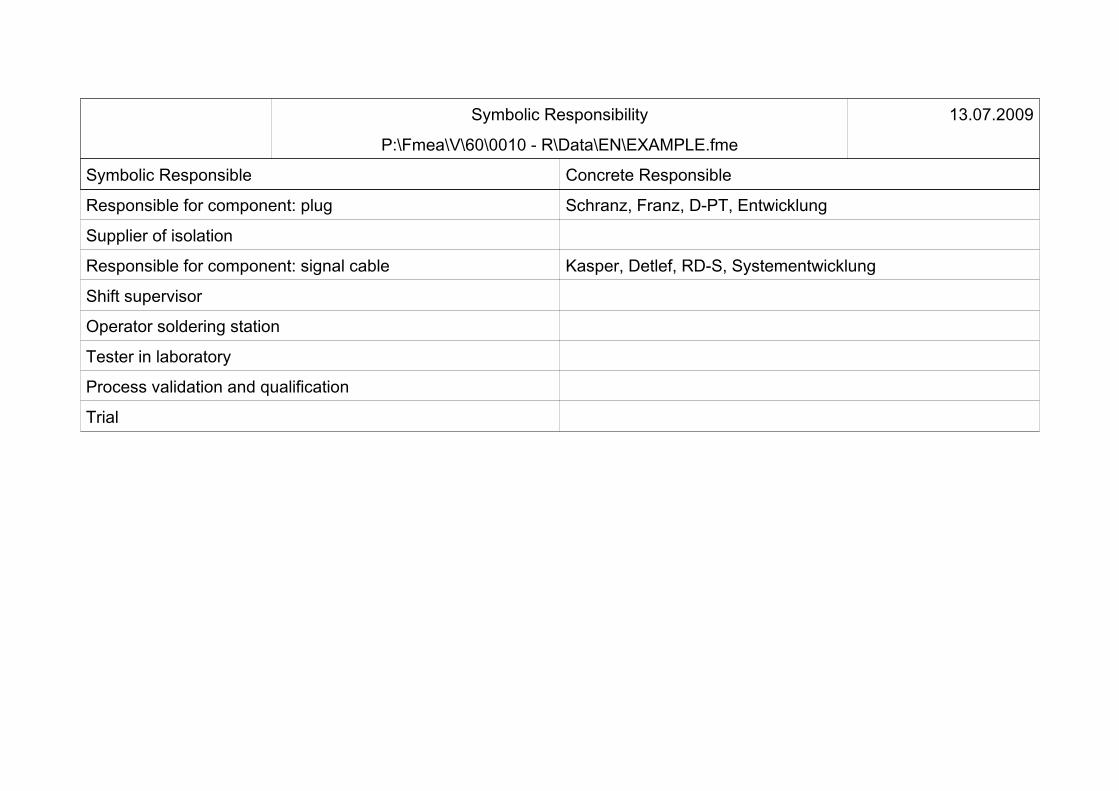
Symbolic Responsibility
P:\Fmea\V\60\0010 - R\Data\EN\EXAMPLE.fme
13.07.2009
Symbolic Responsible Concrete Responsible
Responsible for component: plug Schranz, Franz, D-PT, Entwicklung
Supplier of isolation
Responsible for component: signal cable Kasper, Detlef, RD-S, Systementwicklung
Shift supervisor
Operator soldering station
Tester in laboratory
Process validation and qualification
Trial

Symbolic Deadlines
P:\Fmea\V\60\0010 - R\Data\EN\EXAMPLE.fme
13.07.2009
Symbolic Deadline Concrete Deadline
Release developed components
Quality Gate 03
Quality Gate 02
Presentation concept study

Palette for Process Flow Diagram
P:\Fmea\V\60\0010 - R\Data\EN\EXAMPLE.fme
13.07.2009
Controlplan rele-
vant
Name Standard Internal Notes
Fabrication
Move
Store
Inspect
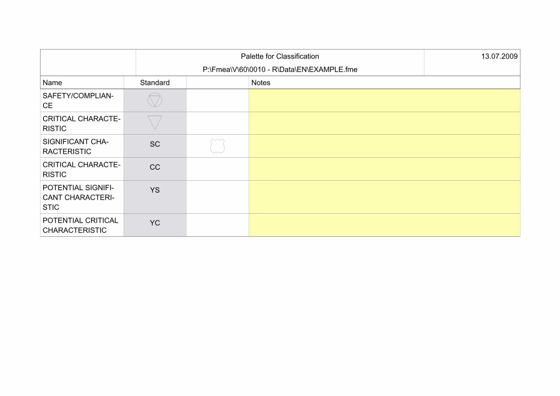
Palette for Classification
P:\Fmea\V\60\0010 - R\Data\EN\EXAMPLE.fme
13.07.2009
Name Standard Notes
SAFETY/COMPLIAN-CE
CRITICAL CHARACTE-RISTIC
SIGNIFICANT CHA-RACTERISTIC
SC
CRITICAL CHARACTE-RISTIC
CC
POTENTIAL SIGNIFI-CANT CHARACTERI-STIC
YS
POTENTIAL CRITICALCHARACTERISTIC
YC

Notes List
Failures
13.07.2009
No data available

Project: Cruise Control Unit CC 2042
creation date: '07.01.2001 14:06:01' by 'Supervisor'.last modification: '07.04.2009 13:32:32' by 'Supervisor'.
Structure: structure 'CC 2042 - system' of type 'System'
creation date: '27.02.2009 12:04:34' by 'Supervisor'.last modification: '07.04.2009 13:32:32' by 'Supervisor'.last modification within the structure '13.07.2009 16:44:20': 1.1.a.1 provides no control pulse
Structure: structure 'CC 2042 - manufacture signal cable' of type 'Process'
creation date: '10.03.2009 12:08:59' by 'Supervisor'.last modification: '07.04.2009 13:32:32' by 'Supervisor'.last modification within the structure '07.04.2009 13:32:32': System Element: 4.8.3 soldering iron (structure 'CC 2042 - manufacture signal cable' of type 'Process').1. Structure Variant (78 excluded and variantspecific Objects and Values):
Structure Variant: Signal cable complete - without reworkcreation date: '07.01.2001 14:57:25' by 'Supervisor'.last modification: '07.04.2009 13:32:32' by 'Supervisor'.2. Structure Variant (23 excluded and variantspecific Objects and Values):
Structure Variant: Signal cable complete - with reworkcreation date: '16.03.2006 17:15:48' by 'Supervisor'.last modification: '07.04.2009 13:32:32' by 'Supervisor'.
Structure: structure 'CC 2042 - signal cable constructive design' of type 'Design'
creation date: '27.02.2009 12:06:52' by 'Supervisor'.last modification: '07.04.2009 13:32:32' by 'Supervisor'.last modification within the structure '07.04.2009 13:32:32': System Element: 2.1.1.4.1 Constructive design solder (structure 'CC 2042 - signal cable constructive design' of type 'Design').

Structure: structure 'Plug - constructive design' of type 'Design'
creation date: '27.02.2009 12:07:42' by 'Supervisor'.last modification: '07.04.2009 13:32:32' by 'Supervisor'.last modification within the structure '07.04.2009 13:32:32': System Element: 3.3.1 Constructive design solder (structure 'Plug - constructive design' of type 'Design').1. Structure Variant (25 excluded and variantspecific Objects and Values):
Structure Variant: Plug - constructive design with soldering connectioncreation date: '08.06.2006 14:48:12' by 'Supervisor'.last modification: '07.04.2009 13:32:32' by 'Supervisor'.2. Structure Variant (31 excluded and variantspecific Objects and Values):
Structure Variant: Plug - constructive design with clamp connectioncreation date: '08.06.2006 14:48:35' by 'Supervisor'.last modification: '07.04.2009 13:32:32' by 'Supervisor'.
FMEA Form: 1.2 Signal cable (complete) (Type: System).
creation date: '05.03.2009 12:05:05' by 'Supervisor'.last modification: '07.04.2009 13:32:32' by 'Supervisor'.FMEA Summary: System Element: 1:
System Element: 1.2 Signal cable (complete) (structure 'CC 2042 - system' of type 'System', Form present).Functions: 7
with cause-effect-information: 7.Failure Modes: 6
with cause-effect-information: 6.Effects: 6
Severity 5: 2Severity 7: 1Severity 9: 3
Causes: 14 (Last rated revision state):
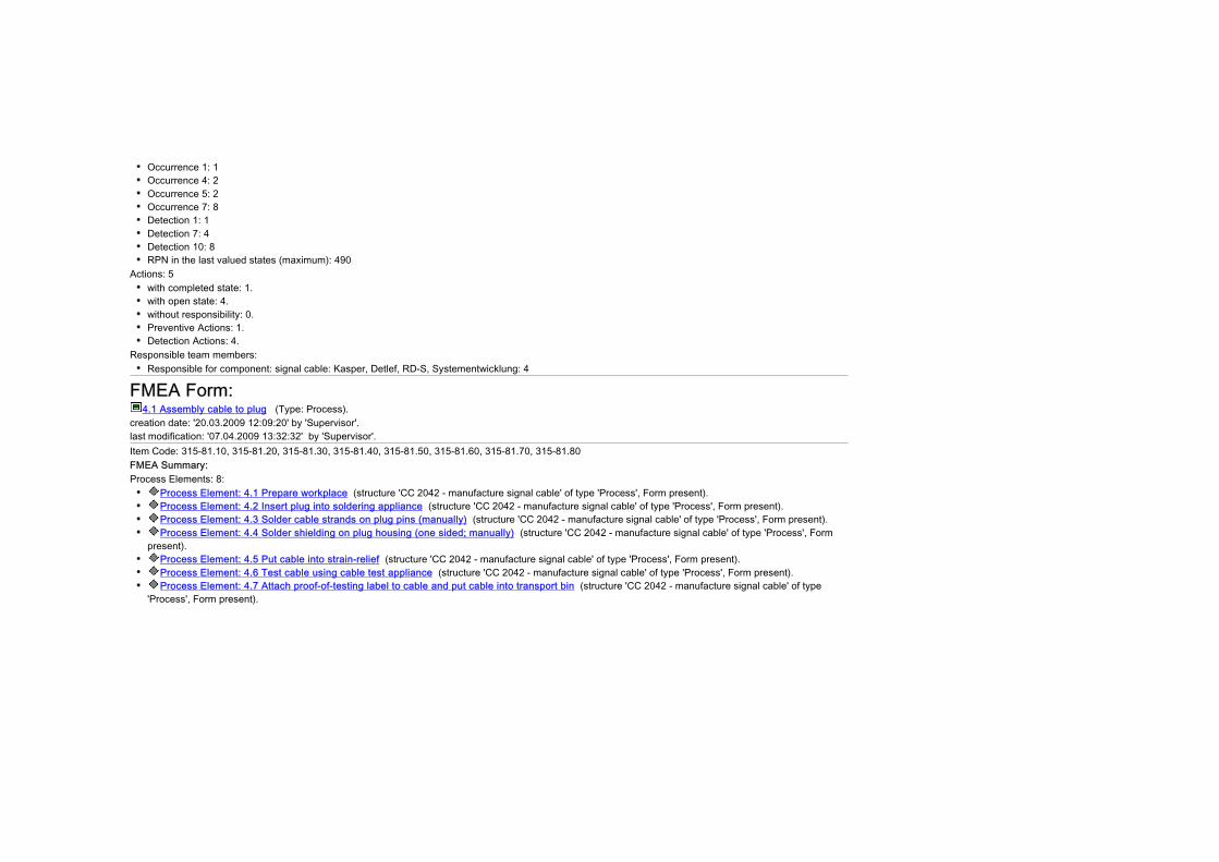
Occurrence 1: 1Occurrence 4: 2Occurrence 5: 2Occurrence 7: 8Detection 1: 1Detection 7: 4Detection 10: 8RPN in the last valued states (maximum): 490
Actions: 5with completed state: 1.with open state: 4.without responsibility: 0.Preventive Actions: 1.Detection Actions: 4.
Responsible team members:Responsible for component: signal cable: Kasper, Detlef, RD-S, Systementwicklung: 4
FMEA Form: 4.1 Assembly cable to plug (Type: Process).
creation date: '20.03.2009 12:09:20' by 'Supervisor'.last modification: '07.04.2009 13:32:32' by 'Supervisor'.Item Code: 315-81.10, 315-81.20, 315-81.30, 315-81.40, 315-81.50, 315-81.60, 315-81.70, 315-81.80FMEA Summary: Process Elements: 8:
Process Element: 4.1 Prepare workplace (structure 'CC 2042 - manufacture signal cable' of type 'Process', Form present).Process Element: 4.2 Insert plug into soldering appliance (structure 'CC 2042 - manufacture signal cable' of type 'Process', Form present).Process Element: 4.3 Solder cable strands on plug pins (manually) (structure 'CC 2042 - manufacture signal cable' of type 'Process', Form present).Process Element: 4.4 Solder shielding on plug housing (one sided; manually) (structure 'CC 2042 - manufacture signal cable' of type 'Process', Form
present).Process Element: 4.5 Put cable into strain-relief (structure 'CC 2042 - manufacture signal cable' of type 'Process', Form present).Process Element: 4.6 Test cable using cable test appliance (structure 'CC 2042 - manufacture signal cable' of type 'Process', Form present).Process Element: 4.7 Attach proof-of-testing label to cable and put cable into transport bin (structure 'CC 2042 - manufacture signal cable' of type
'Process', Form present).
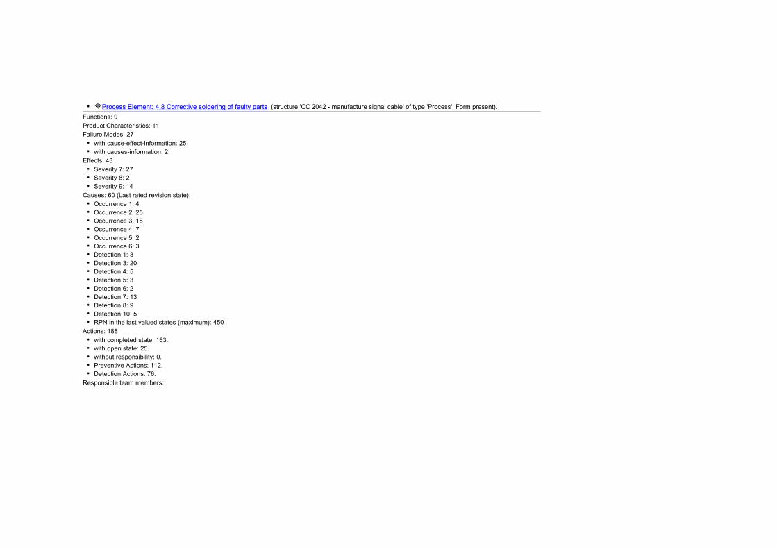
Process Element: 4.8 Corrective soldering of faulty parts (structure 'CC 2042 - manufacture signal cable' of type 'Process', Form present).Functions: 9Product Characteristics: 11Failure Modes: 27
with cause-effect-information: 25.with causes-information: 2.
Effects: 43Severity 7: 27Severity 8: 2Severity 9: 14
Causes: 60 (Last rated revision state):Occurrence 1: 4Occurrence 2: 25Occurrence 3: 18Occurrence 4: 7Occurrence 5: 2Occurrence 6: 3Detection 1: 3Detection 3: 20Detection 4: 5Detection 5: 3Detection 6: 2Detection 7: 13Detection 8: 9Detection 10: 5RPN in the last valued states (maximum): 450
Actions: 188with completed state: 163.with open state: 25.without responsibility: 0.Preventive Actions: 112.Detection Actions: 76.
Responsible team members:

Bonewski, Hans, D-PT, Entwicklung: 16Hehre, Claudia, FV-PO, Prozessplanung: 4Operator soldering station: 14Priebke, Claas, D-PT, Entwicklung: 3Seetzen, Gudrun, D-PT, Entwicklung: 2Shift supervisor: 20
FMEA Form: 2.1 Signal cable (complete) (Type: Design).
creation date: '05.03.2009 12:07:01' by 'Supervisor'.last modification: '07.04.2009 13:32:32' by 'Supervisor'.FMEA Summary: System Element: 1:
System Element: 2.1 Electrical connections (structure 'CC 2042 - signal cable constructive design' of type 'Design', Form present).Functions: 3
with cause-effect-information: 3.Product Characteristics: 3
with cause-effect-information: 3.Failure Modes: 5
with cause-effect-information: 5.Effects: 5
Severity 5: 1Severity 7: 1Severity 9: 2
Causes: 17 (Last rated revision state):Occurrence 1: 1Occurrence 5: 1Occurrence 7: 6Detection 1: 1Detection 7: 3Detection 10: 4RPN in the last valued states (maximum): 630

Actions: 4with completed state: 1.with open state: 3.without responsibility: 0.Preventive Actions: 1.Detection Actions: 3.
Responsible team members:Responsible for component: signal cable: Kasper, Detlef, RD-S, Systementwicklung: 3
FMEA Form: 3.1 Plug (Type: Design).
creation date: '05.03.2009 12:07:48' by 'Supervisor'.last modification: '07.04.2009 13:32:32' by 'Supervisor'.FMEA Summary: System Elements: 3:
System Element: 3.1 Contact pin (structure 'Plug - constructive design' of type 'Design', Form present).System Element: 3.2 Plug body (structure 'Plug - constructive design' of type 'Design', Form present).System Element: 3.3 soldering connection between wire and pin (structure 'Plug - constructive design' of type 'Design', Form present).
Functions: 13with cause-effect-information: 12.
Failure Modes: 21with cause-effect-information: 21.
Effects: 33Causes: 51 (Last rated revision state):
Occurrence 3: 23Occurrence 4: 23Detection 3: 19Detection 4: 22Detection 5: 1Detection 6: 3Detection 7: 2RPN in the last valued states (maximum): 288
Actions: 159

with completed state: 91.with open state: 68.without responsibility: 0.Preventive Actions: 84.Detection Actions: 75.
Responsible team members:Priebke, Claas, D-PT, Entwicklung: 5Process validation and qualification: 3Responsible for component: plug: Schranz, Franz, D-PT, Entwicklung: 25Responsible for component: signal cable: Kasper, Detlef, RD-S, Systementwicklung: 1Santy, David, ZQS, Qualitätsentwicklung: 21Seetzen, Gudrun, D-PT, Entwicklung: 5Trial: 16
FMEA Form: 2.1.1.3 Cabel (Type: Design).
creation date: '05.03.2009 12:08:22' by 'Supervisor'.last modification: '07.04.2009 13:32:32' by 'Supervisor'.FMEA Summary: System Elements: 4:
System Element: 2.1.1.3 Shielding (structure 'CC 2042 - signal cable constructive design' of type 'Design', Form present).System Element: 2.1.1.2 Isolation (structure 'CC 2042 - signal cable constructive design' of type 'Design', Form present).System Element: 2.1.1.1 conductor (structure 'CC 2042 - signal cable constructive design' of type 'Design', Form present).System Element: 2.1.1.4 Soldering connection shielding (structure 'CC 2042 - signal cable constructive design' of type 'Design', Form present).
Functions: 4with cause-effect-information: 2.
Product Characteristics: 6with cause-effect-information: 6.
Failure Modes: 12with cause-effect-information: 11.with effect-information: 1.
Effects: 18

Causes: 21 (Last rated revision state):Occurrence 3: 4Occurrence 4: 17Detection 2: 3Detection 3: 15Detection 4: 3RPN in the last valued states (maximum): 108
Actions: 85with completed state: 42.with open state: 43.without responsibility: 0.Preventive Actions: 43.Detection Actions: 42.
Responsible team members:Responsible for component: plug: Schranz, Franz, D-PT, Entwicklung: 4Responsible for component: signal cable: Kasper, Detlef, RD-S, Systementwicklung: 8Santy, David, ZQS, Qualitätsentwicklung: 21Trial: 10
DRBFM Formsheet: Steckerkontakt
creation date: '27.06.2006 08:58:39' by 'Supervisor'.last modification: '07.04.2009 13:32:32' by 'Supervisor'.System Elements: 2:
System Element: 3.1 Contact pin (structure 'Plug - constructive design' of type 'Design', Form present).System Element: 3.3 soldering connection between wire and pin (structure 'Plug - constructive design' of type 'Design', Form present).
Missing translations (2): French, Italian
DRBFM Formsheet: Steckerkörper
creation date: '27.06.2006 09:01:42' by 'Supervisor'.last modification: '07.04.2009 13:32:32' by 'Supervisor'.System Element: 1:
System Element: 3.2 Plug body (structure 'Plug - constructive design' of type 'Design', Form present).Missing translations (2): French, Italian
DRBFM Formsheet: elektrischer Leiter
creation date: '27.06.2006 09:03:09' by 'Supervisor'.last modification: '07.04.2009 13:32:32' by 'Supervisor'.System Element: 1:
System Element: 2.1.1.1 conductor (structure 'CC 2042 - signal cable constructive design' of type 'Design', Form present).Missing translations (2): French, Italian
DRBFM Formsheet: Abschirmung
creation date: '27.06.2006 09:04:06' by 'Supervisor'.last modification: '07.04.2009 13:32:32' by 'Supervisor'.System Elements: 2:
System Element: 2.1.1.3 Shielding (structure 'CC 2042 - signal cable constructive design' of type 'Design', Form present).System Element: 2.1.1.4 Soldering connection shielding (structure 'CC 2042 - signal cable constructive design' of type 'Design', Form present).
Missing translations (2): French, Italian
Control Plan: CP 001-4.0 Assembly signal cable (complete)
creation date: '06.03.2006 18:17:50' by 'Supervisor'.last modification: '07.04.2009 13:32:32' by 'Supervisor'.Characteristics: 11.Actions: 22
with completed state: 22.with open state: 0.without responsibility: 0.Preventive Actions: 14.Detection Actions: 8.
Responsible team members:
Operator soldering station: 10Shift supervisor: 12
Process Elements: 6:Process Element: 4.1 Prepare workplace (structure 'CC 2042 - manufacture signal cable' of type 'Process', Form present).Process Element: 4.3 Solder cable strands on plug pins (manually) (structure 'CC 2042 - manufacture signal cable' of type 'Process', Form present).Process Element: 4.4 Solder shielding on plug housing (one sided; manually) (structure 'CC 2042 - manufacture signal cable' of type 'Process', Form
present).Process Element: 4.5 Put cable into strain-relief (structure 'CC 2042 - manufacture signal cable' of type 'Process', Form present).Process Element: 4.7 Attach proof-of-testing label to cable and put cable into transport bin (structure 'CC 2042 - manufacture signal cable' of type
'Process', Form present).Process Element: 4.8 Corrective soldering of faulty parts (structure 'CC 2042 - manufacture signal cable' of type 'Process', Form present).
soldering workplace #4.3testing workplace #4.7soldering workplace corrective work #4.12check by shift supervisorvisual inspectiontest appliance: cable functiontest appliance: pull-off strengthohm meter
Control Plan: CP 001-2.1 Electric conductor
creation date: '17.03.2006 11:58:38' by 'Supervisor'.last modification: '07.04.2009 13:32:32' by 'Supervisor'.Characteristics: 6.System Elements: 6:
System Element: 2.1.1.1 conductor (structure 'CC 2042 - signal cable constructive design' of type 'Design', Form present).System Element: 2.1.1.2 Isolation (structure 'CC 2042 - signal cable constructive design' of type 'Design', Form present).System Element: 2.1.1.3 Shielding (structure 'CC 2042 - signal cable constructive design' of type 'Design', Form present).System Element: 3.1 Contact pin (structure 'Plug - constructive design' of type 'Design', Form present).System Element: 3.2 Plug body (structure 'Plug - constructive design' of type 'Design', Form present).System Element: 3.3 soldering connection between wire and pin (structure 'Plug - constructive design' of type 'Design', Form present).
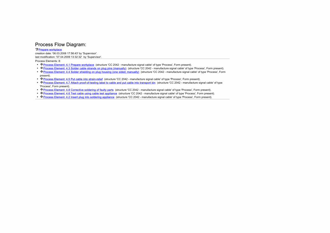
Process Flow Diagram: Prepare workplace
creation date: '06.03.2006 17:56:43' by 'Supervisor'.last modification: '07.04.2009 13:32:32' by 'Supervisor'.Process Elements: 8:
Process Element: 4.1 Prepare workplace (structure 'CC 2042 - manufacture signal cable' of type 'Process', Form present).Process Element: 4.3 Solder cable strands on plug pins (manually) (structure 'CC 2042 - manufacture signal cable' of type 'Process', Form present).Process Element: 4.4 Solder shielding on plug housing (one sided; manually) (structure 'CC 2042 - manufacture signal cable' of type 'Process', Form
present).Process Element: 4.5 Put cable into strain-relief (structure 'CC 2042 - manufacture signal cable' of type 'Process', Form present).Process Element: 4.7 Attach proof-of-testing label to cable and put cable into transport bin (structure 'CC 2042 - manufacture signal cable' of type
'Process', Form present).Process Element: 4.8 Corrective soldering of faulty parts (structure 'CC 2042 - manufacture signal cable' of type 'Process', Form present).Process Element: 4.6 Test cable using cable test appliance (structure 'CC 2042 - manufacture signal cable' of type 'Process', Form present).Process Element: 4.2 Insert plug into soldering appliance (structure 'CC 2042 - manufacture signal cable' of type 'Process', Form present).

Cruise Control SC 2042 Electrical connections
Cable
conductor Construction design of conductor
Isolation Constructive design of isolation
Shielding Constructive design shielding
Soldering connection shielding Constructive design solder
Plug

2 Cruise Control SC 2042 2.a control propulsion according to specification {2}
S=9 2.a.1 drive control is out of specification {2} S=7 2.a.2 drive cannot be controlled {2} 2.a.3 loss of function during life-time {2} 2.a.4 cruise control in failure mode {2}
2.b enable emergency shutoff in critical situations {2} 2.c signal state of operation {2} 2.d meet legal requirements {2}
S=9 2.d.1 does not comply with requirements regarding electromagnetic radiation {2} 2.e comply with customers assembly requirements {2}
S=5 2.e.1 does not comply with customer requirements regarding replaceability of components {2} 2.1 Electrical connections
2.1.a transport signals from sensor to control unit without loss {2} 2.1.b transport signals from control unit to speed control without loss {2} 2.1.c resist environmental conditions {2}
2.1.c.1 does not resist environmental conditions over life-time {2} 2.1.d transmission properties of complete cable regarding application conditions {1}
2.1.d.1 no signal {2} 2.1.d.2 signal does not represent the input values correctly {2}
2.1.e properties of cable regarding electromagnetic radiation {1} 2.1.e.1 electromagnetic radiation exceeds specified limit {2}
2.1.f ease of exchange {1} 2.1.f.1 exchange not possible without damaging cable {2}
2.1.1 Cable 2.1.1.a strength durability : f = ? {1} 2.1.1.1 conductor
2.1.1.1.a solderability of conductor {1} 2.1.1.1.a.1 inadequate solderability of conductor {1}
2.1.1.1.b transmission of signal through voltage level 32 Ns ±1 {1} 2.1.1.1.b.1 level of signal decreases during transmission within the given application conditions {1}O=5 D=10 Initial State 05.03.2009
simulation under known application conditions {3}

NONE {29} 2.1.1.1.b.2 specified signal level drops signifcantly below critical limit {2}O=1 D=1 Initial State 05.03.2009
2.1.1.1.c transmission of signal through modulation 11 Ns {1} 2.1.1.1.c.1 modulation of signal changes during transmission within the given application conditions {4}O=7 D=10 Initial State 05.03.2009
NONE {27}NONE {29}
O=7 D=7 Revision State 05.03.2009 [ Deadline? (in progress) Responsible for component: signal cable: Kasper, Detlef, RD-S, Systementwicklung]simulation of transmission (favored concept) under currently known application conditions {9}
2.1.1.1.d mechanical stability of conductor 37,2 MPa {1} 2.1.1.1.d.1 has insufficient mechanical stability {4}O=7 D=10 Initial State 05.03.2009
NONE {27}NONE {29}
2.1.1.1.1 Construction design of conductor 2.1.1.1.1.a conductor material {1}
2.1.1.1.1.a.1 inadequate conductor material chosen {1}O=3 D=5 Initial State 05.03.2009
experience from earlier development projects {16}material test with plate sample {5}
O=4 D=3 Revision State 05.03.2009examination of different coatings in the soldering area {2} [ 22.04.2009 (in progress) Responsible for component: signal cable: Kasper, Detlef, RD-S, Systementwicklung]life-time simulation with focus on vibration resistance {8} [ 15.05.2009 (in progress) Trial]tests with prototypes {28} [ 02.04.2009 (in progress) Santy, David, ZQS, Qualitätsentwicklung]
2.1.1.1.1.b conductor cross section {1} 2.1.1.1.1.b.1 wrong dimension of cross section {1}O=3 D=3 Initial State 05.03.2009
experience from earlier development projects {16}tests with prototypes {28}
O=4 D=2 Revision State 05.03.2009 [ 02.04.2009 (in progress) Santy, David, ZQS, Qualitätsentwicklung]tests with prototype {17}
2.1.1.1.1.c conductor length {1}
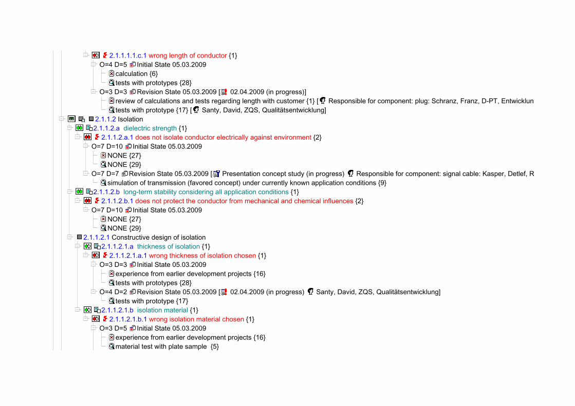
2.1.1.1.1.c.1 wrong length of conductor {1}O=4 D=5 Initial State 05.03.2009
calculation {6}tests with prototypes {28}
O=3 D=3 Revision State 05.03.2009 [ 02.04.2009 (in progress)]review of calculations and tests regarding length with customer {1} [ Responsible for component: plug: Schranz, Franz, D-PT, Entwicklung]tests with prototype {17} [ Santy, David, ZQS, Qualitätsentwicklung]
2.1.1.2 Isolation 2.1.1.2.a dielectric strength {1}
2.1.1.2.a.1 does not isolate conductor electrically against environment {2}O=7 D=10 Initial State 05.03.2009
NONE {27}NONE {29}
O=7 D=7 Revision State 05.03.2009 [ Presentation concept study (in progress) Responsible for component: signal cable: Kasper, Detlef, RD-S, Systementwicklung]simulation of transmission (favored concept) under currently known application conditions {9}
2.1.1.2.b long-term stability considering all application conditions {1} 2.1.1.2.b.1 does not protect the conductor from mechanical and chemical influences {2}O=7 D=10 Initial State 05.03.2009
NONE {27}NONE {29}
2.1.1.2.1 Constructive design of isolation 2.1.1.2.1.a thickness of isolation {1}
2.1.1.2.1.a.1 wrong thickness of isolation chosen {1}O=3 D=3 Initial State 05.03.2009
experience from earlier development projects {16}tests with prototypes {28}
O=4 D=2 Revision State 05.03.2009 [ 02.04.2009 (in progress) Santy, David, ZQS, Qualitätsentwicklung]tests with prototype {17}
2.1.1.2.1.b isolation material {1} 2.1.1.2.1.b.1 wrong isolation material chosen {1}O=3 D=5 Initial State 05.03.2009
experience from earlier development projects {16}material test with plate sample {5}
O=4 D=3 Revision State 05.03.2009 [ 02.04.2009 (in progress) Santy, David, ZQS, Qualitätsentwicklung]tests with prototypes {28}
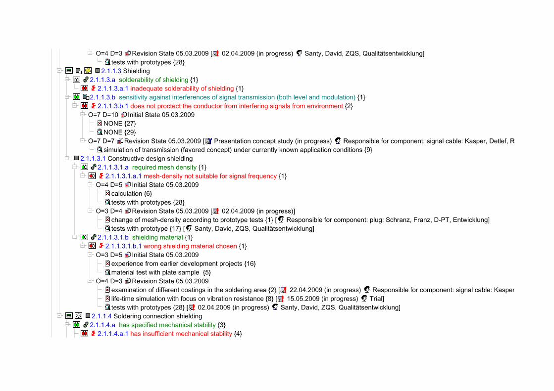
2.1.1.3 Shielding 2.1.1.3.a solderability of shielding {1}
2.1.1.3.a.1 inadequate solderability of shielding {1} 2.1.1.3.b sensitivity against interferences of signal transmission (both level and modulation) {1}
2.1.1.3.b.1 does not proctect the conductor from interfering signals from environment {2}O=7 D=10 Initial State 05.03.2009
NONE {27}NONE {29}
O=7 D=7 Revision State 05.03.2009 [ Presentation concept study (in progress) Responsible for component: signal cable: Kasper, Detlef, RD-S, Systementwicklung]simulation of transmission (favored concept) under currently known application conditions {9}
2.1.1.3.1 Constructive design shielding 2.1.1.3.1.a required mesh density {1}
2.1.1.3.1.a.1 mesh-density not suitable for signal frequency {1}O=4 D=5 Initial State 05.03.2009
calculation {6}tests with prototypes {28}
O=3 D=4 Revision State 05.03.2009 [ 02.04.2009 (in progress)]change of mesh-density according to prototype tests {1} [ Responsible for component: plug: Schranz, Franz, D-PT, Entwicklung]tests with prototype {17} [ Santy, David, ZQS, Qualitätsentwicklung]
2.1.1.3.1.b shielding material {1} 2.1.1.3.1.b.1 wrong shielding material chosen {1}O=3 D=5 Initial State 05.03.2009
experience from earlier development projects {16}material test with plate sample {5}
O=4 D=3 Revision State 05.03.2009examination of different coatings in the soldering area {2} [ 22.04.2009 (in progress) Responsible for component: signal cable: Kasper, Detlef, RD-S, Systementwicklung]life-time simulation with focus on vibration resistance {8} [ 15.05.2009 (in progress) Trial]tests with prototypes {28} [ 02.04.2009 (in progress) Santy, David, ZQS, Qualitätsentwicklung]
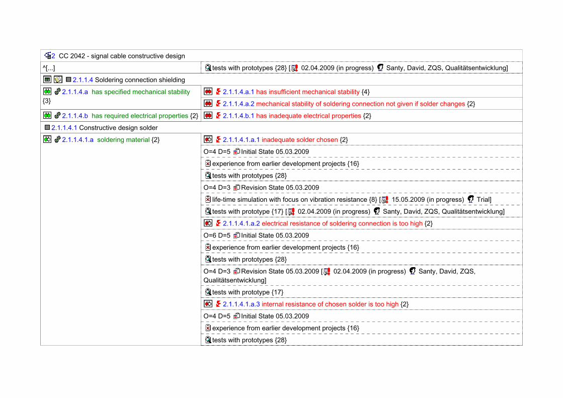
2.1.1.4 Soldering connection shielding 2.1.1.4.a has specified mechanical stability {3}
2.1.1.4.a.1 has insufficient mechanical stability {4}
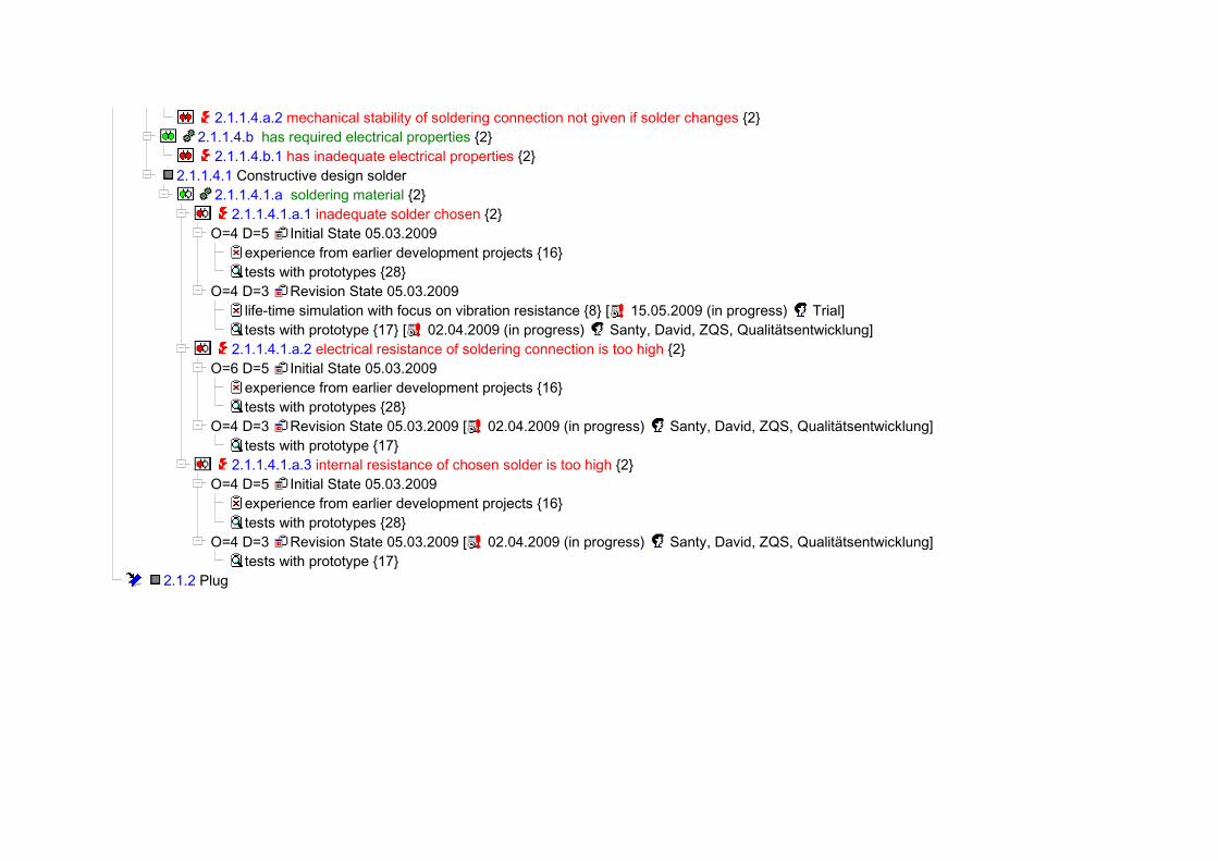
2.1.1.4.a.2 mechanical stability of soldering connection not given if solder changes {2} 2.1.1.4.b has required electrical properties {2}
2.1.1.4.b.1 has inadequate electrical properties {2}2.1.1.4.1 Constructive design solder
2.1.1.4.1.a soldering material {2} 2.1.1.4.1.a.1 inadequate solder chosen {2}O=4 D=5 Initial State 05.03.2009
experience from earlier development projects {16}tests with prototypes {28}
O=4 D=3 Revision State 05.03.2009life-time simulation with focus on vibration resistance {8} [ 15.05.2009 (in progress) Trial]tests with prototype {17} [ 02.04.2009 (in progress) Santy, David, ZQS, Qualitätsentwicklung]
2.1.1.4.1.a.2 electrical resistance of soldering connection is too high {2}O=6 D=5 Initial State 05.03.2009
experience from earlier development projects {16}tests with prototypes {28}
O=4 D=3 Revision State 05.03.2009 [ 02.04.2009 (in progress) Santy, David, ZQS, Qualitätsentwicklung]tests with prototype {17}
2.1.1.4.1.a.3 internal resistance of chosen solder is too high {2}O=4 D=5 Initial State 05.03.2009
experience from earlier development projects {16}tests with prototypes {28}
O=4 D=3 Revision State 05.03.2009 [ 02.04.2009 (in progress) Santy, David, ZQS, Qualitätsentwicklung]tests with prototype {17}
2.1.2 Plug

2 CC 2042 - signal cable constructive design
2 Cruise Control SC 2042
2.a control propulsion according to specification {2}
S=9 2.a.1 drive control is out of specification {2}
S=7 2.a.2 drive cannot be controlled {2}
2.a.3 loss of function during life-time {2}
2.a.4 cruise control in failure mode {2}
2.b enable emergency shutoff in critical situations {2}
2.c signal state of operation {2}
2.d meet legal requirements {2} S=9 2.d.1 does not comply with requirements regarding electromagnetic radiation {2}
2.e comply with customers assembly requirements {2}
S=5 2.e.1 does not comply with customer requirements regarding replaceability of components {2}
2.1 Electrical connections
2.1.a transport signals from sensor to control unit without loss {2}
2.1.b transport signals from control unit to speed control without loss {2}
2.1.c resist environmental conditions {2} 2.1.c.1 does not resist environmental conditions over life-time {2}
2.1.d transmission properties of complete cable regarding application conditions {1}
2.1.d.1 no signal {2}
2.1.d.2 signal does not represent the input values correctly {2}
2.1.e properties of cable regarding electromagnetic radiation {1}
2.1.e.1 electromagnetic radiation exceeds specified limit {2}
2.1.f ease of exchange {1} 2.1.f.1 exchange not possible without damaging cable {2}
2.1.1 Cable
2.1.1.a strength durability : f = ? {1}
2.1.1.1 conductor
2.1.1.1.a solderability of conductor {1} 2.1.1.1.a.1 inadequate solderability of conductor {1}
2 CC 2042 - signal cable constructive design
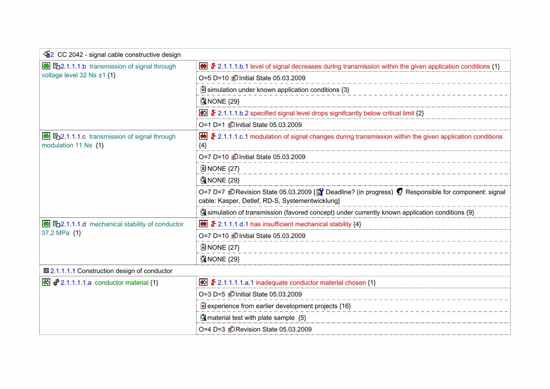
2.1.1.1.b transmission of signal through voltage level 32 Ns ±1 {1}
2.1.1.1.b.1 level of signal decreases during transmission within the given application conditions {1}
O=5 D=10 Initial State 05.03.2009
simulation under known application conditions {3}
NONE {29}
2.1.1.1.b.2 specified signal level drops signifcantly below critical limit {2}
O=1 D=1 Initial State 05.03.2009
2.1.1.1.c transmission of signal through modulation 11 Ns {1}
2.1.1.1.c.1 modulation of signal changes during transmission within the given application conditions {4}
O=7 D=10 Initial State 05.03.2009
NONE {27}
NONE {29}
O=7 D=7 Revision State 05.03.2009 [ Deadline? (in progress) Responsible for component: signal cable: Kasper, Detlef, RD-S, Systementwicklung]
simulation of transmission (favored concept) under currently known application conditions {9}
2.1.1.1.d mechanical stability of conductor 37,2 MPa {1}
2.1.1.1.d.1 has insufficient mechanical stability {4}
O=7 D=10 Initial State 05.03.2009
NONE {27}
NONE {29}
2.1.1.1.1 Construction design of conductor
2.1.1.1.1.a conductor material {1} 2.1.1.1.1.a.1 inadequate conductor material chosen {1}
O=3 D=5 Initial State 05.03.2009
experience from earlier development projects {16}
material test with plate sample {5}
O=4 D=3 Revision State 05.03.2009
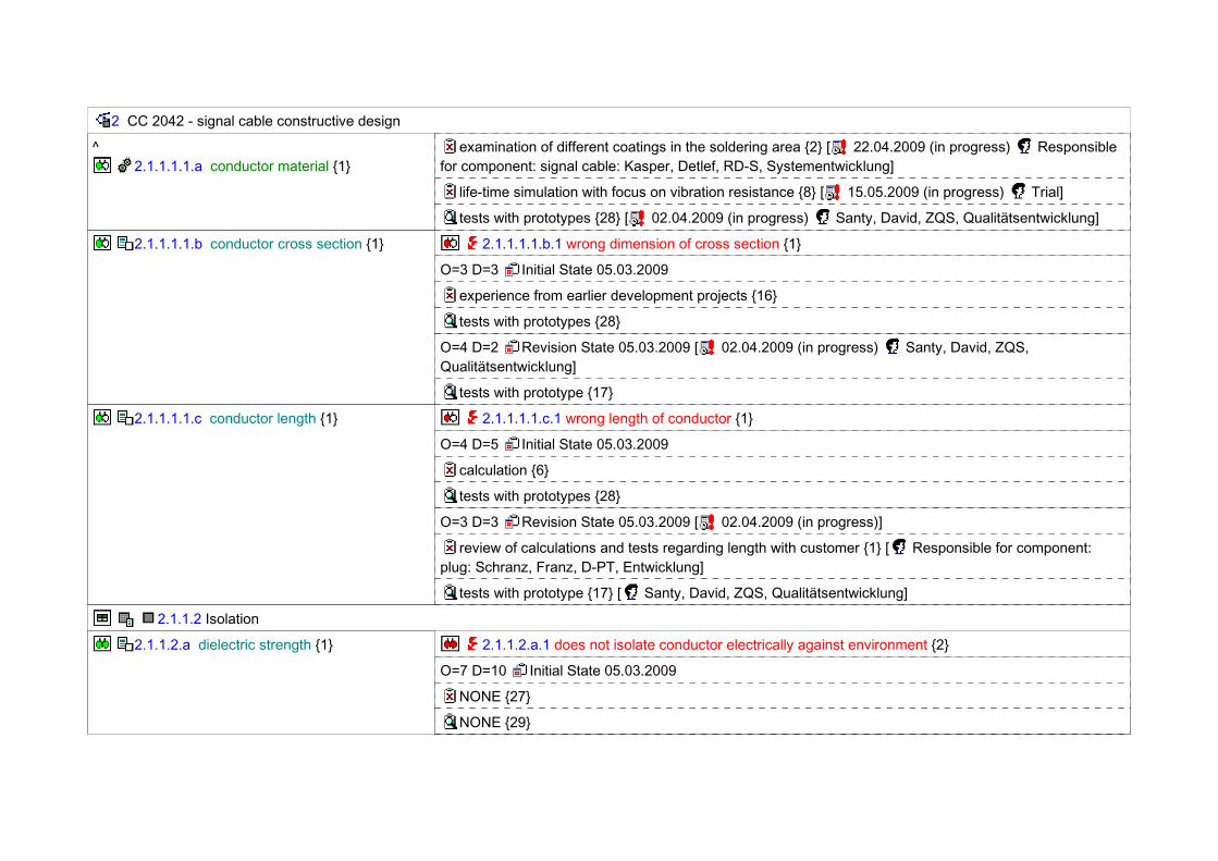
2 CC 2042 - signal cable constructive design
^ 2.1.1.1.1.a conductor material {1}
examination of different coatings in the soldering area {2} [ 22.04.2009 (in progress) Responsible for component: signal cable: Kasper, Detlef, RD-S, Systementwicklung]
life-time simulation with focus on vibration resistance {8} [ 15.05.2009 (in progress) Trial]
tests with prototypes {28} [ 02.04.2009 (in progress) Santy, David, ZQS, Qualitätsentwicklung]
2.1.1.1.1.b conductor cross section {1} 2.1.1.1.1.b.1 wrong dimension of cross section {1}
O=3 D=3 Initial State 05.03.2009
experience from earlier development projects {16}
tests with prototypes {28}
O=4 D=2 Revision State 05.03.2009 [ 02.04.2009 (in progress) Santy, David, ZQS, Qualitätsentwicklung]
tests with prototype {17}
2.1.1.1.1.c conductor length {1} 2.1.1.1.1.c.1 wrong length of conductor {1}
O=4 D=5 Initial State 05.03.2009
calculation {6}
tests with prototypes {28}
O=3 D=3 Revision State 05.03.2009 [ 02.04.2009 (in progress)]
review of calculations and tests regarding length with customer {1} [ Responsible for component: plug: Schranz, Franz, D-PT, Entwicklung]
tests with prototype {17} [ Santy, David, ZQS, Qualitätsentwicklung]
2.1.1.2 Isolation
2.1.1.2.a dielectric strength {1} 2.1.1.2.a.1 does not isolate conductor electrically against environment {2}
O=7 D=10 Initial State 05.03.2009
NONE {27}
NONE {29}

2 CC 2042 - signal cable constructive design
^ 2.1.1.2.a dielectric strength {1}
O=7 D=7 Revision State 05.03.2009 [ Presentation concept study (in progress) Responsible for component: signal cable: Kasper, Detlef, RD-S, Systementwicklung]
simulation of transmission (favored concept) under currently known application conditions {9}
2.1.1.2.b long-term stability considering all application conditions {1}
2.1.1.2.b.1 does not protect the conductor from mechanical and chemical influences {2}
O=7 D=10 Initial State 05.03.2009
NONE {27}
NONE {29}
2.1.1.2.1 Constructive design of isolation
2.1.1.2.1.a thickness of isolation {1} 2.1.1.2.1.a.1 wrong thickness of isolation chosen {1}
O=3 D=3 Initial State 05.03.2009
experience from earlier development projects {16}
tests with prototypes {28}
O=4 D=2 Revision State 05.03.2009 [ 02.04.2009 (in progress) Santy, David, ZQS, Qualitätsentwicklung]
tests with prototype {17}
2.1.1.2.1.b isolation material {1} 2.1.1.2.1.b.1 wrong isolation material chosen {1}
O=3 D=5 Initial State 05.03.2009
experience from earlier development projects {16}
material test with plate sample {5}
O=4 D=3 Revision State 05.03.2009 [ 02.04.2009 (in progress) Santy, David, ZQS, Qualitätsentwicklung]
tests with prototypes {28}
2.1.1.3 Shielding
2.1.1.3.a solderability of shielding {1} 2.1.1.3.a.1 inadequate solderability of shielding {1}

2 CC 2042 - signal cable constructive design
2.1.1.3.b sensitivity against interferences of signal transmission (both level and modulation) {1}
2.1.1.3.b.1 does not proctect the conductor from interfering signals from environment {2}
O=7 D=10 Initial State 05.03.2009
NONE {27}
NONE {29}
O=7 D=7 Revision State 05.03.2009 [ Presentation concept study (in progress) Responsible for component: signal cable: Kasper, Detlef, RD-S, Systementwicklung]
simulation of transmission (favored concept) under currently known application conditions {9}
2.1.1.3.1 Constructive design shielding
2.1.1.3.1.a required mesh density {1} 2.1.1.3.1.a.1 mesh-density not suitable for signal frequency {1}
O=4 D=5 Initial State 05.03.2009
calculation {6}
tests with prototypes {28}
O=3 D=4 Revision State 05.03.2009 [ 02.04.2009 (in progress)]
change of mesh-density according to prototype tests {1} [ Responsible for component: plug: Schranz, Franz, D-PT, Entwicklung]
tests with prototype {17} [ Santy, David, ZQS, Qualitätsentwicklung]
2.1.1.3.1.b shielding material {1} 2.1.1.3.1.b.1 wrong shielding material chosen {1}
O=3 D=5 Initial State 05.03.2009
experience from earlier development projects {16}
material test with plate sample {5}
O=4 D=3 Revision State 05.03.2009
examination of different coatings in the soldering area {2} [ 22.04.2009 (in progress) Responsible for component: signal cable: Kasper, Detlef, RD-S, Systementwicklung]
life-time simulation with focus on vibration resistance {8} [ 15.05.2009 (in progress) Trial]
2 CC 2042 - signal cable constructive design
^[...] tests with prototypes {28} [ 02.04.2009 (in progress) Santy, David, ZQS, Qualitätsentwicklung]
2.1.1.4 Soldering connection shielding
2.1.1.4.a has specified mechanical stability {3}
2.1.1.4.a.1 has insufficient mechanical stability {4}
2.1.1.4.a.2 mechanical stability of soldering connection not given if solder changes {2}
2.1.1.4.b has required electrical properties {2} 2.1.1.4.b.1 has inadequate electrical properties {2}
2.1.1.4.1 Constructive design solder
2.1.1.4.1.a soldering material {2} 2.1.1.4.1.a.1 inadequate solder chosen {2}
O=4 D=5 Initial State 05.03.2009
experience from earlier development projects {16}
tests with prototypes {28}
O=4 D=3 Revision State 05.03.2009
life-time simulation with focus on vibration resistance {8} [ 15.05.2009 (in progress) Trial]
tests with prototype {17} [ 02.04.2009 (in progress) Santy, David, ZQS, Qualitätsentwicklung]
2.1.1.4.1.a.2 electrical resistance of soldering connection is too high {2}
O=6 D=5 Initial State 05.03.2009
experience from earlier development projects {16}
tests with prototypes {28}
O=4 D=3 Revision State 05.03.2009 [ 02.04.2009 (in progress) Santy, David, ZQS, Qualitätsentwicklung]
tests with prototype {17}
2.1.1.4.1.a.3 internal resistance of chosen solder is too high {2}
O=4 D=5 Initial State 05.03.2009
experience from earlier development projects {16}
tests with prototypes {28}

2 CC 2042 - signal cable constructive design
^ 2.1.1.4.1.a soldering material {2}
O=4 D=3 Revision State 05.03.2009 [ 02.04.2009 (in progress) Santy, David, ZQS, Qualitätsentwicklung]
tests with prototype {17}
2.1.2 Plug

1 2 3 4 5 6 7 8 9 10 11 12 13 14 15 16 17 18 19 20 21 22 23 24 25 26 27 280
100
200
300
400
500
600
0 0102030405060708090100
0
Pareto AnalysisLast revision state; RPN
Causes
RP
N
Ris
k P
ortio
n [in
%]

1 2 3 4 5 6 7 8 9 10 11 12 13 14 15 16 17 18 19 20 21 22 23 24 25 26 27 280
100
200
300
400
500
600
0
Difference AnalysisAll revision states; RPN; Sort by: New value (after)
Causes
RP
N
Initial state
More recent state
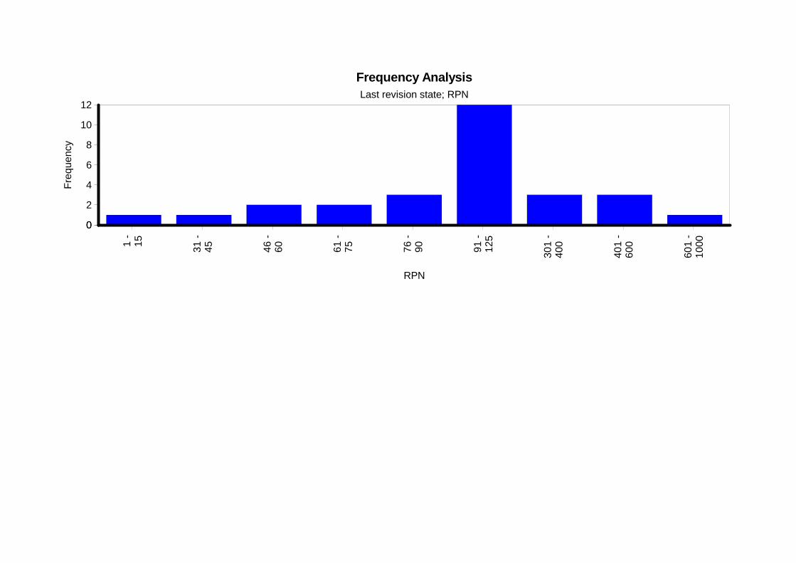
1 -
15 31 -
45 46
-
60 61 -
75 76
-
90 91 -
12
5
301
- 40
0
401
- 60
0
601
- 10
00
0
2
4
6
8
10
12
0
Frequency AnalysisLast revision state; RPN
RPN
Fre
quen
cy

Bon
ewsk
i
Heh
re
Kas
per
Ope
rato
r so
lder
ing
sta.
..
Pea
ch
Prie
bke
Pro
cess
val
idat
ion
and.
..
Res
pons
ible
for
com
pon.
..
Res
pons
ible
for
com
pon.
..
San
ty
Sch
ranz
See
tzen
Shi
ft su
perv
isor
Sup
ervi
sor
Sup
plie
r of
isol
atio
n
Tes
ter
in la
bora
tory
Tria
l
0123456789
10
0
Responsibility Analysis
Responsibility
Num
ber
of A
ctio
ns

10
9
8
7 1 2 3
6
5 1
4 2 3 11
3 2 2
2
1 1
O/S 1 2 3 4 5 6 7 8 9 10
Risk MatrixLast revision state
Causes Red Area: 23 Yellow Area: 4 Green Area: 1

1/23
F M E A
System
Number: 1.2
Page:
Type/Model/Fabrication/Load:CC 2042 - system
Item Code:
State:
Responsible:
Company:
Created: 27.02.2009
FMEA/System Element:Signal cable (complete)
Item Code:
State:
Responsible:
Company:
Created: 05.03.2009
Modified: 07.04.2009
Effects S Failure Modes Causes C Preventive Action O Detection Action D RPN R/D
1/23
System Element: Signal cable (complete)
Function: allow manual assembly {1}
does not comply with customer requirements regarding assembly force {1}
5 (5) special tools for assembly required {1}
> force to establish plug connection is too high {1}
>> geometry of contact pin and plug contact badly aligned {1}
Initial State: 05.03.2009
calculation {6} 4 tests with prototypes {28}
5 100
State: 05.03.2009
coordination regarding geometry of contact pin with developers of plug contact {1}
Responsible for compo-nent: plug: Schranz,Franz, D-PT, Entwicklung
3 tests with prototype {17}
Santy, David, ZQS, Quali-tätsentwicklung
4 (60) Responsible for co-mponent: plug:Schranz, Franz,D-PT, Entwicklung,Santy, David, ZQS,Qualitätsentwicklung
02.04.2009in progress
required force is too high {2} Initial State: 05.03.2009
NONE {27} 4 NONE {29} 10 200
>> snap-in is too tight {1} Initial State: 05.03.2009
calculation {6} 4 tests with prototypes {28}
7 140
Function: allow multiple exchange {1}
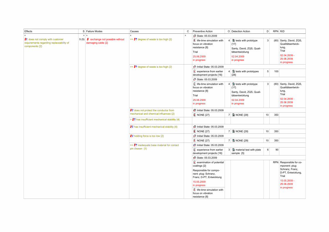
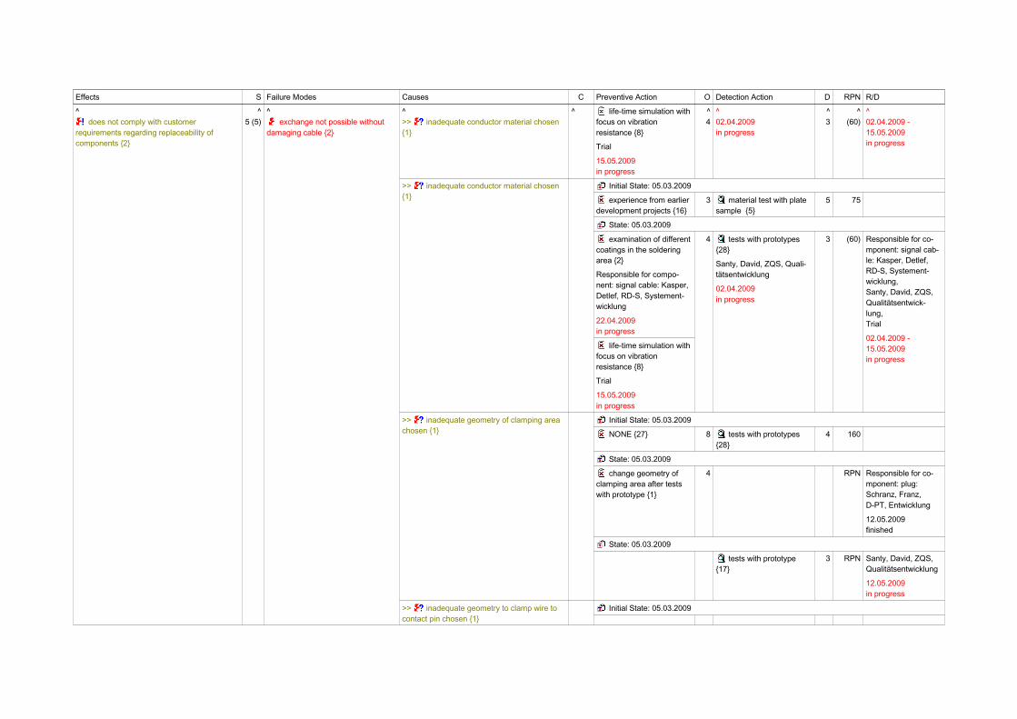
does not comply with customer requirements regarding replaceability of components {2}
5 (5) exchange not possible without damaging cable {2}
> contact force between wire and contact is not sufficient {1}
>> cross section too small and/or unsuitable mechanical pin geometry {1}
Initial State: 05.03.2009
FEM simulation {1} 4 tests with prototypes {28}
5 100
>> degree of waste is too high {2} Initial State: 05.03.2009
experience from earlier development projects {16}
4 tests with prototypes {28}
5 100
Effects S Failure Modes Causes C Preventive Action O Detection Action D RPN R/D
^ does not comply with customer
requirements regarding replaceability of components {2}
^5 (5)
^ exchange not possible without
damaging cable {2}
^>> degree of waste is too high {2}
^ State: 05.03.2009
life-time simulation with focus on vibration resistance {8}
Trial
25.06.2009in progress
4 tests with prototype {17}
Santy, David, ZQS, Quali-tätsentwicklung
02.04.2009in progress
3 (60) Santy, David, ZQS,Qualitätsentwick-lung,Trial
02.04.2009 -25.06.2009in progress
>> degree of waste is too high {2} Initial State: 05.03.2009
experience from earlier development projects {16}
4 tests with prototypes {28}
5 100
State: 05.03.2009
life-time simulation with focus on vibration resistance {8}
Trial
25.06.2009in progress
4 tests with prototype {17}
Santy, David, ZQS, Quali-tätsentwicklung
02.04.2009in progress
3 (60) Santy, David, ZQS,Qualitätsentwick-lung,Trial
02.04.2009 -25.06.2009in progress
does not protect the conductor from mechanical and chemical influences {2}
Initial State: 05.03.2009
NONE {27} 7 NONE {29} 10 350
> has insufficient mechanical stability {4}
has insufficient mechanical stability {4} Initial State: 05.03.2009
NONE {27} 7 NONE {29} 10 350
holding force is too low {2} Initial State: 05.03.2009
NONE {27} 7 NONE {29} 10 350
>> inadequate base material for contact pin chosen {1}
Initial State: 05.03.2009
experience from earlier development projects {16}
3 material test with plate sample {5}
6 90
State: 05.03.2009
examination of potentialcoatings {2}
Responsible for compo-nent: plug: Schranz,Franz, D-PT, Entwicklung
15.05.2009in progress
life-time simulation with focus on vibration resistance {8}
RPN Responsible for co-mponent: plug:Schranz, Franz,D-PT, Entwicklung,Trial
15.05.2009 -25.06.2009in progress

Effects S Failure Modes Causes C Preventive Action O Detection Action D RPN R/D
^ does not comply with customer
requirements regarding replaceability of components {2}
^5 (5)
^ exchange not possible without
damaging cable {2}
^>> inadequate base material for contact pin chosen {1}
^ Trial
25.06.2009in progress
^RPN
^15.05.2009 -[...]
>> inadequate base material for contact pin chosen {1}
Initial State: 05.03.2009
experience from earlier development projects {16}
3 material test with plate sample {5}
6 90
State: 05.03.2009
examination of potentialcoatings {2}
Responsible for compo-nent: plug: Schranz,Franz, D-PT, Entwicklung
15.05.2009in progress
life-time simulation with focus on vibration resistance {8}
Trial
25.06.2009in progress
RPN Responsible for co-mponent: plug:Schranz, Franz,D-PT, Entwicklung,Trial
15.05.2009 -25.06.2009in progress
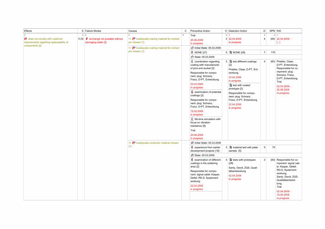
>> inadequate coating material for contact pin chosen {1}
Initial State: 05.03.2009
NONE {27} 5 NONE {29} 7 175
State: 05.03.2009
coordination regarding coating with manufacturer of pins and socket {2}
Responsible for compo-nent: plug: Schranz,Franz, D-PT, Entwicklung
22.04.2009in progress
examination of potentialcoatings {2}
Responsible for compo-nent: plug: Schranz,Franz, D-PT, Entwicklung
15.05.2009in progress
life-time simulation with focus on vibration resistance {8}
3 test different coatings {2}
Priebke, Claas, D-PT, Ent-wicklung
22.04.2009in progress
test with coated prototype {2}
Responsible for compo-nent: plug: Schranz,Franz, D-PT, Entwicklung
22.04.2009in progress
4 (60) Priebke, Claas,D-PT, Entwicklung,Responsible for co-mponent: plug:Schranz, Franz,D-PT, Entwicklung,Trial
22.04.2009 -25.06.2009in progress
Effects S Failure Modes Causes C Preventive Action O Detection Action D RPN R/D
^ does not comply with customer
requirements regarding replaceability of components {2}
^5 (5)
^ exchange not possible without
damaging cable {2}
^>> inadequate coating material for contact pin chosen {1}
^ Trial
25.06.2009in progress
^3
^22.04.2009in progress
^4
^(60)
^22.04.2009 -[...]
>> inadequate coating material for contact pin chosen {1}
Initial State: 05.03.2009
NONE {27} 5 NONE {29} 7 175
State: 05.03.2009
coordination regarding coating with manufacturer of pins and socket {2}
Responsible for compo-nent: plug: Schranz,Franz, D-PT, Entwicklung
22.04.2009in progress
examination of potentialcoatings {2}
Responsible for compo-nent: plug: Schranz,Franz, D-PT, Entwicklung
15.05.2009in progress
life-time simulation with focus on vibration resistance {8}
Trial
25.06.2009in progress
3 test different coatings {2}
Priebke, Claas, D-PT, Ent-wicklung
22.04.2009in progress
test with coated prototype {2}
Responsible for compo-nent: plug: Schranz,Franz, D-PT, Entwicklung
22.04.2009in progress
4 (60) Priebke, Claas,D-PT, Entwicklung,Responsible for co-mponent: plug:Schranz, Franz,D-PT, Entwicklung,Trial
22.04.2009 -25.06.2009in progress
>> inadequate conductor material chosen {1}
Initial State: 05.03.2009
experience from earlier development projects {16}
3 material test with plate sample {5}
5 75
State: 05.03.2009
examination of different coatings in the soldering area {2}
Responsible for compo-nent: signal cable: Kasper,Detlef, RD-S, Systement-wicklung
22.04.2009in progress
4 tests with prototypes {28}
Santy, David, ZQS, Quali-tätsentwicklung
02.04.2009in progress
3 (60) Responsible for co-mponent: signal cab-le: Kasper, Detlef,RD-S, Systement-wicklung,Santy, David, ZQS,Qualitätsentwick-lung,Trial
02.04.2009 -15.05.2009in progress
Effects S Failure Modes Causes C Preventive Action O Detection Action D RPN R/D
^ does not comply with customer
requirements regarding replaceability of components {2}
^5 (5)
^ exchange not possible without
damaging cable {2}
^>> inadequate conductor material chosen {1}
^ life-time simulation with focus on vibration resistance {8}
Trial
15.05.2009in progress
^4
^02.04.2009in progress
^3
^(60)
^02.04.2009 -15.05.2009in progress
>> inadequate conductor material chosen {1}
Initial State: 05.03.2009
experience from earlier development projects {16}
3 material test with plate sample {5}
5 75
State: 05.03.2009
examination of different coatings in the soldering area {2}
Responsible for compo-nent: signal cable: Kasper,Detlef, RD-S, Systement-wicklung
22.04.2009in progress
life-time simulation with focus on vibration resistance {8}
Trial
15.05.2009in progress
4 tests with prototypes {28}
Santy, David, ZQS, Quali-tätsentwicklung
02.04.2009in progress
3 (60) Responsible for co-mponent: signal cab-le: Kasper, Detlef,RD-S, Systement-wicklung,Santy, David, ZQS,Qualitätsentwick-lung,Trial
02.04.2009 -15.05.2009in progress
>> inadequate geometry of clamping area chosen {1}
Initial State: 05.03.2009
NONE {27} 8 tests with prototypes {28}
4 160
State: 05.03.2009
change geometry of clamping area after tests with prototype {1}
4 RPN Responsible for co-mponent: plug:Schranz, Franz,D-PT, Entwicklung
12.05.2009finished
State: 05.03.2009
tests with prototype {17}
3 RPN Santy, David, ZQS,Qualitätsentwicklung
12.05.2009in progress
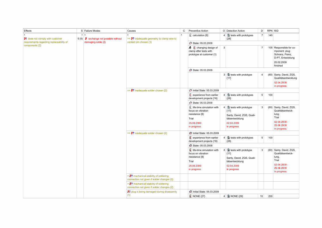
>> inadequate geometry to clamp wire to contact pin chosen {1}
Initial State: 05.03.2009
Effects S Failure Modes Causes C Preventive Action O Detection Action D RPN R/D
^ does not comply with customer
requirements regarding replaceability of components {2}
^5 (5)
^ exchange not possible without
damaging cable {2}
^>> inadequate geometry to clamp wire to contact pin chosen {1}
^ calculation {6} 4 tests with prototypes {28}
7 140
State: 05.03.2009
changing design of clamp after tests with prototype at customer {1}
3 7 105 Responsible for co-mponent: plug:Schranz, Franz,D-PT, Entwicklung
20.02.2009finished
State: 05.03.2009
3 tests with prototype {17}
4 (60) Santy, David, ZQS,Qualitätsentwicklung
02.04.2009in progress
>> inadequate solder chosen {2} Initial State: 05.03.2009
experience from earlier development projects {16}
4 tests with prototypes {28}
5 100
State: 05.03.2009
life-time simulation with focus on vibration resistance {8}
Trial
25.06.2009in progress
4 tests with prototype {17}
Santy, David, ZQS, Quali-tätsentwicklung
02.04.2009in progress
3 (60) Santy, David, ZQS,Qualitätsentwick-lung,Trial
02.04.2009 -25.06.2009in progress
> mechanical stability of soldering connection not given if solder changes {2}
> mechanical stability of soldering connection not given if solder changes {2}
plug is being damaged during disassemly {1}
Initial State: 05.03.2009
NONE {27} 4 NONE {29} 10 200
Effects S Failure Modes Causes C Preventive Action O Detection Action D RPN R/D
^ does not comply with customer
requirements regarding replaceability of components {2}
^5 (5)
^ exchange not possible without
damaging cable {2}
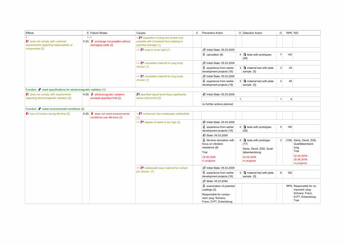
> separation of plug and socket only possible with increased force leading to potential damage {1}
>> snap-in is too tight {1} Initial State: 05.03.2009
calculation {6} 4 tests with prototypes {28}
7 140
>> unsuitable material for plug body chosen {1}
Initial State: 05.03.2009
experience from earlier development projects {16}
3 material test with plate sample {5}
3 45
>> unsuitable material for plug body chosen {1}
Initial State: 05.03.2009
experience from earlier development projects {16}
3 material test with plate sample {5}
3 45
Function: meet specifications for electromagnetic radiation {1}
does not comply with requirements regarding electromagnetic radiation {2}
9 (9) electromagnetic radiation exceeds specified limit {2}
specified signal level drops signifcantly below critical limit {2}
Initial State: 05.03.2009
1 1 9
no further actions planned
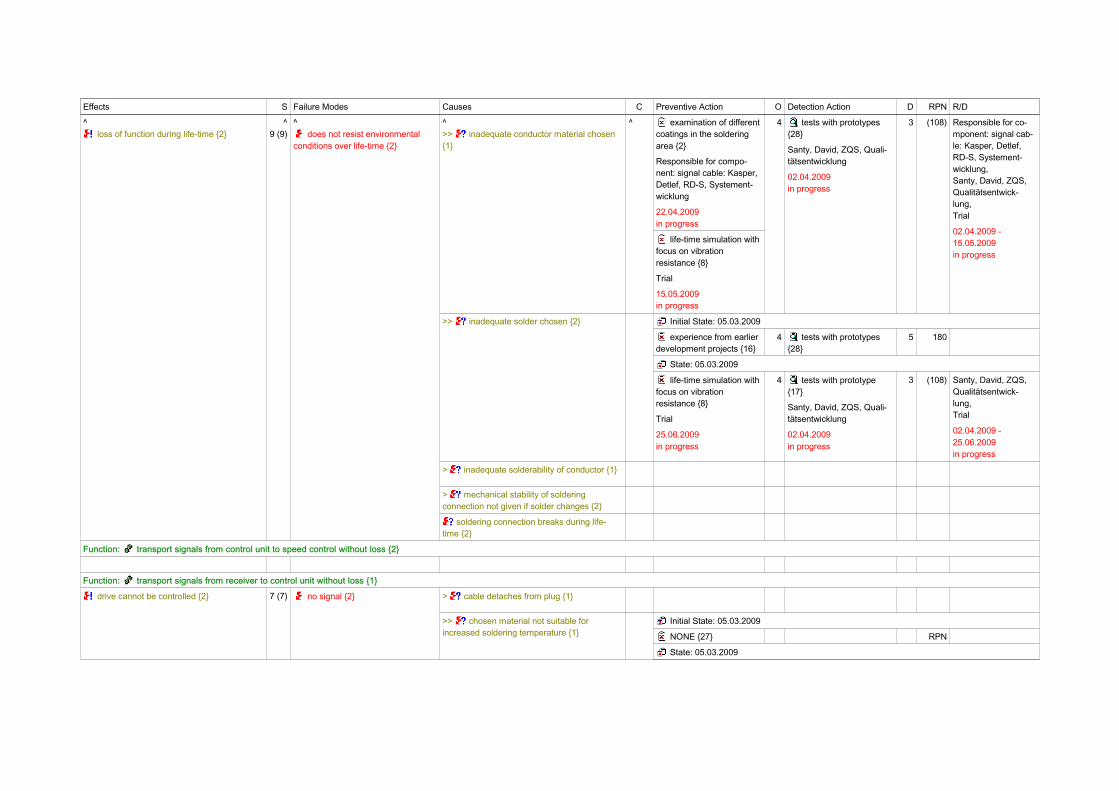
Function: resist environmental conditions {2}
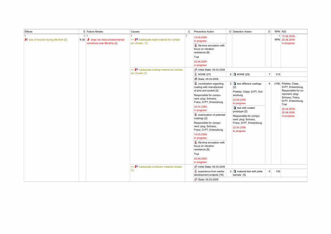
loss of function during life-time {2} 9 (9) does not resist environmental conditions over life-time {2}
> contact pin has inadequate solderability {1}
>> degree of waste is too high {2} Initial State: 05.03.2009
experience from earlier development projects {16}
4 tests with prototypes {28}
5 180
State: 05.03.2009
life-time simulation with focus on vibration resistance {8}
Trial
25.06.2009in progress
4 tests with prototype {17}
Santy, David, ZQS, Quali-tätsentwicklung
02.04.2009in progress
3 (108) Santy, David, ZQS,Qualitätsentwick-lung,Trial
02.04.2009 -25.06.2009in progress
>> inadequate base material for contact pin chosen {1}
Initial State: 05.03.2009
experience from earlier development projects {16}
3 material test with plate sample {5}
6 162
State: 05.03.2009
examination of potentialcoatings {2}
Responsible for compo-nent: plug: Schranz,Franz, D-PT, Entwicklung
RPN Responsible for co-mponent: plug:Schranz, Franz,D-PT, Entwicklung,Trial
Effects S Failure Modes Causes C Preventive Action O Detection Action D RPN R/D
^ loss of function during life-time {2}
^9 (9)
^ does not resist environmental
conditions over life-time {2}
^>> inadequate base material for contact pin chosen {1}
^ 15.05.2009in progress
life-time simulation with focus on vibration resistance {8}
Trial
25.06.2009in progress
^RPN
15.05.2009 -25.06.2009in progress
>> inadequate coating material for contact pin chosen {1}
Initial State: 05.03.2009
NONE {27} 5 NONE {29} 7 315
State: 05.03.2009
coordination regarding coating with manufacturer of pins and socket {2}
Responsible for compo-nent: plug: Schranz,Franz, D-PT, Entwicklung
22.04.2009in progress
examination of potentialcoatings {2}
Responsible for compo-nent: plug: Schranz,Franz, D-PT, Entwicklung
15.05.2009in progress
life-time simulation with focus on vibration resistance {8}
Trial
25.06.2009in progress
3 test different coatings {2}
Priebke, Claas, D-PT, Ent-wicklung
22.04.2009in progress
test with coated prototype {2}
Responsible for compo-nent: plug: Schranz,Franz, D-PT, Entwicklung
22.04.2009in progress
4 (108) Priebke, Claas,D-PT, Entwicklung,Responsible for co-mponent: plug:Schranz, Franz,D-PT, Entwicklung,Trial
22.04.2009 -25.06.2009in progress
>> inadequate conductor material chosen {1}
Initial State: 05.03.2009
experience from earlier development projects {16}
3 material test with plate sample {5}
5 135
State: 05.03.2009
Effects S Failure Modes Causes C Preventive Action O Detection Action D RPN R/D
^ loss of function during life-time {2}
^9 (9)
^ does not resist environmental
conditions over life-time {2}
^>> inadequate conductor material chosen {1}
^ examination of different coatings in the soldering area {2}
Responsible for compo-nent: signal cable: Kasper,Detlef, RD-S, Systement-wicklung
22.04.2009in progress
life-time simulation with focus on vibration resistance {8}
Trial
15.05.2009in progress
4 tests with prototypes {28}
Santy, David, ZQS, Quali-tätsentwicklung
02.04.2009in progress
3 (108) Responsible for co-mponent: signal cab-le: Kasper, Detlef,RD-S, Systement-wicklung,Santy, David, ZQS,Qualitätsentwick-lung,Trial
02.04.2009 -15.05.2009in progress
>> inadequate solder chosen {2} Initial State: 05.03.2009
experience from earlier development projects {16}
4 tests with prototypes {28}
5 180
State: 05.03.2009
life-time simulation with focus on vibration resistance {8}
Trial
25.06.2009in progress
4 tests with prototype {17}
Santy, David, ZQS, Quali-tätsentwicklung
02.04.2009in progress
3 (108) Santy, David, ZQS,Qualitätsentwick-lung,Trial
02.04.2009 -25.06.2009in progress
> inadequate solderability of conductor {1}
> mechanical stability of soldering connection not given if solder changes {2}
soldering connection breaks during life-time {2}
Function: transport signals from control unit to speed control without loss {2}
Function: transport signals from receiver to control unit without loss {1}
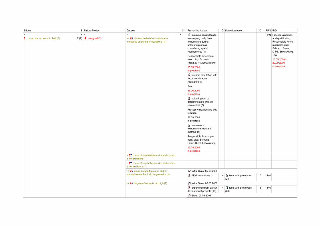
drive cannot be controlled {2} 7 (7) no signal {2} > cable detaches from plug {1}
>> chosen material not suitable for increased soldering temperature {1}
Initial State: 05.03.2009
NONE {27} RPN
State: 05.03.2009
Effects S Failure Modes Causes C Preventive Action O Detection Action D RPN R/D
^ drive cannot be controlled {2}
^7 (7)
^ no signal {2}
^>> chosen material not suitable for increased soldering temperature {1}
^ examine possibilites to isolate plug body from temperature during soldering process considering spatial requirements {1}
Responsible for compo-nent: plug: Schranz,Franz, D-PT, Entwicklung
15.05.2009in progress
life-time simulation with focus on vibration resistance {8}
Trial
25.06.2009in progress
soldering test to determine safe process parameters {2}
Process validation and qua-lification
22.09.2009in progress
use a more temperature resistant material {1}
Responsible for compo-nent: plug: Schranz,Franz, D-PT, Entwicklung
15.05.2009in progress
RPN Process validationand qualification,Responsible for co-mponent: plug:Schranz, Franz,D-PT, Entwicklung,Trial
15.05.2009 -22.09.2009in progress
> contact force between wire and contact is not sufficient {1}
> contact force between wire and contact is not sufficient {1}
>> cross section too small and/or unsuitable mechanical pin geometry {1}
Initial State: 05.03.2009
FEM simulation {1} 4 tests with prototypes {28}
5 140
>> degree of waste is too high {2} Initial State: 05.03.2009
experience from earlier development projects {16}
4 tests with prototypes {28}
5 140
State: 05.03.2009
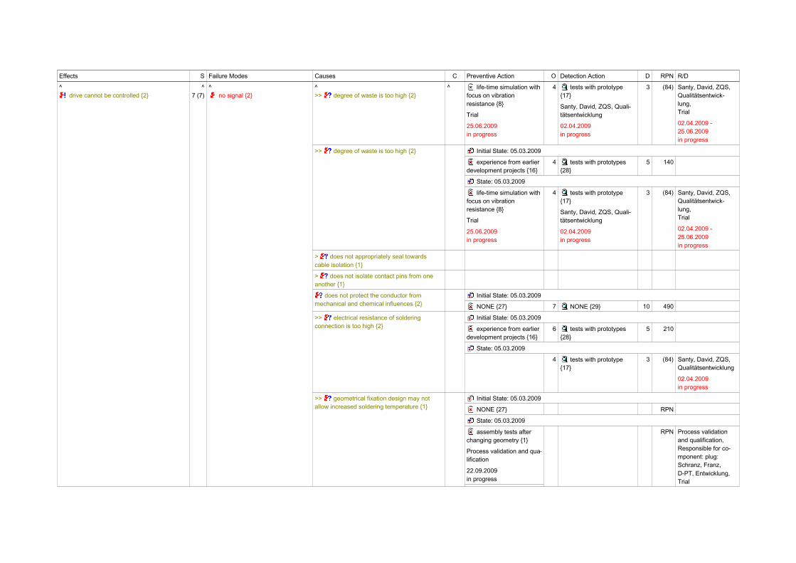
Effects S Failure Modes Causes C Preventive Action O Detection Action D RPN R/D
^ drive cannot be controlled {2}
^7 (7)
^ no signal {2}
^>> degree of waste is too high {2}
^ life-time simulation with focus on vibration resistance {8}
Trial
25.06.2009in progress
4 tests with prototype {17}
Santy, David, ZQS, Quali-tätsentwicklung
02.04.2009in progress
3 (84) Santy, David, ZQS,Qualitätsentwick-lung,Trial
02.04.2009 -25.06.2009in progress
>> degree of waste is too high {2} Initial State: 05.03.2009
experience from earlier development projects {16}
4 tests with prototypes {28}
5 140
State: 05.03.2009
life-time simulation with focus on vibration resistance {8}
Trial
25.06.2009in progress
4 tests with prototype {17}
Santy, David, ZQS, Quali-tätsentwicklung
02.04.2009in progress
3 (84) Santy, David, ZQS,Qualitätsentwick-lung,Trial
02.04.2009 -25.06.2009in progress
> does not appropriately seal towards cable isolation {1}
> does not isolate contact pins from one another {1}
does not protect the conductor from mechanical and chemical influences {2}
Initial State: 05.03.2009
NONE {27} 7 NONE {29} 10 490
>> electrical resistance of soldering connection is too high {2}
Initial State: 05.03.2009
experience from earlier development projects {16}
6 tests with prototypes {28}
5 210
State: 05.03.2009
4 tests with prototype {17}
3 (84) Santy, David, ZQS,Qualitätsentwicklung
02.04.2009in progress
>> geometrical fixation design may not allow increased soldering temperature {1}
Initial State: 05.03.2009
NONE {27} RPN
State: 05.03.2009
assembly tests after changing geometry {1}
Process validation and qua-lification
22.09.2009in progress
RPN Process validationand qualification,Responsible for co-mponent: plug:Schranz, Franz,D-PT, Entwicklung,Trial

Effects S Failure Modes Causes C Preventive Action O Detection Action D RPN R/D
^ drive cannot be controlled {2}
^7 (7)
^ no signal {2}
^>> geometrical fixation design may not allow increased soldering temperature {1}
^ change fixation geometry concerning soldering temperature {1}
Responsible for compo-nent: plug: Schranz,Franz, D-PT, Entwicklung
15.05.2009in progress
life-time simulation with focus on effects of vibration after changing geometry {1}
Trial
25.06.2009in progress
soldering test to determine safe process parameters {2}
Process validation and qua-lification
22.09.2009in progress
^RPN
15.05.2009 -22.09.2009in progress
>> geometry of contact pin and plug contact badly aligned {1}
Initial State: 05.03.2009
calculation {6} 4 tests with prototypes {28}
5 140
State: 05.03.2009
coordination regarding geometry of contact pin with developers of plug contact {1}
Responsible for compo-nent: plug: Schranz,Franz, D-PT, Entwicklung
3 tests with prototype {17}
Santy, David, ZQS, Quali-tätsentwicklung
4 (84) Responsible for co-mponent: plug:Schranz, Franz,D-PT, Entwicklung,Santy, David, ZQS,Qualitätsentwicklung
02.04.2009in progress
> has inadequate electrical properties {2}
> has insufficient mechanical stability {4}
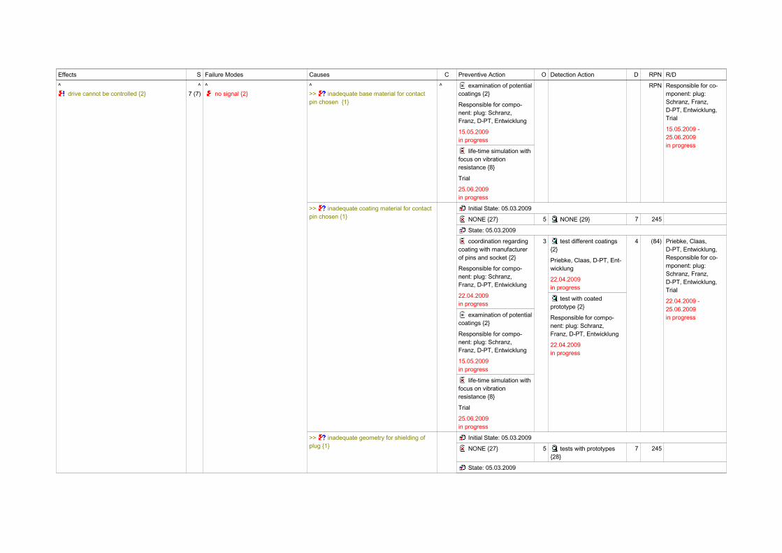
>> inadequate base material for contact pin chosen {1}
Initial State: 05.03.2009
experience from earlier development projects {16}
3 material test with plate sample {5}
6 126
State: 05.03.2009
Effects S Failure Modes Causes C Preventive Action O Detection Action D RPN R/D
^ drive cannot be controlled {2}
^7 (7)
^ no signal {2}
^>> inadequate base material for contact pin chosen {1}
^ examination of potentialcoatings {2}
Responsible for compo-nent: plug: Schranz,Franz, D-PT, Entwicklung
15.05.2009in progress
life-time simulation with focus on vibration resistance {8}
Trial
25.06.2009in progress
RPN Responsible for co-mponent: plug:Schranz, Franz,D-PT, Entwicklung,Trial
15.05.2009 -25.06.2009in progress
>> inadequate coating material for contact pin chosen {1}
Initial State: 05.03.2009
NONE {27} 5 NONE {29} 7 245
State: 05.03.2009
coordination regarding coating with manufacturer of pins and socket {2}
Responsible for compo-nent: plug: Schranz,Franz, D-PT, Entwicklung
22.04.2009in progress
examination of potentialcoatings {2}
Responsible for compo-nent: plug: Schranz,Franz, D-PT, Entwicklung
15.05.2009in progress
life-time simulation with focus on vibration resistance {8}
Trial
25.06.2009in progress
3 test different coatings {2}
Priebke, Claas, D-PT, Ent-wicklung
22.04.2009in progress
test with coated prototype {2}
Responsible for compo-nent: plug: Schranz,Franz, D-PT, Entwicklung
22.04.2009in progress
4 (84) Priebke, Claas,D-PT, Entwicklung,Responsible for co-mponent: plug:Schranz, Franz,D-PT, Entwicklung,Trial
22.04.2009 -25.06.2009in progress
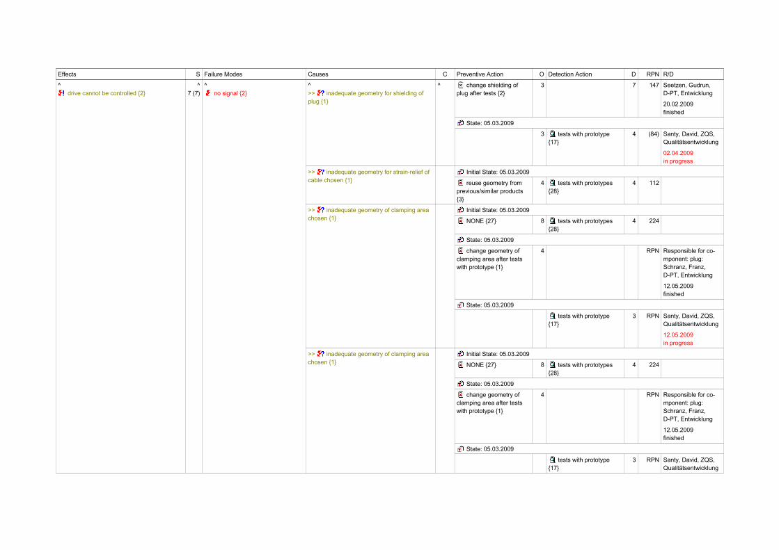
>> inadequate geometry for shielding of plug {1}
Initial State: 05.03.2009
NONE {27} 5 tests with prototypes {28}
7 245
State: 05.03.2009
Effects S Failure Modes Causes C Preventive Action O Detection Action D RPN R/D
^ drive cannot be controlled {2}
^7 (7)
^ no signal {2}
^>> inadequate geometry for shielding of plug {1}
^ change shielding of plug after tests {2}
3 7 147 Seetzen, Gudrun,D-PT, Entwicklung
20.02.2009finished
State: 05.03.2009
3 tests with prototype {17}
4 (84) Santy, David, ZQS,Qualitätsentwicklung
02.04.2009in progress
>> inadequate geometry for strain-relief of cable chosen {1}
Initial State: 05.03.2009
reuse geometry from previous/similar products {3}
4 tests with prototypes {28}
4 112
>> inadequate geometry of clamping area chosen {1}
Initial State: 05.03.2009
NONE {27} 8 tests with prototypes {28}
4 224
State: 05.03.2009
change geometry of clamping area after tests with prototype {1}
4 RPN Responsible for co-mponent: plug:Schranz, Franz,D-PT, Entwicklung
12.05.2009finished
State: 05.03.2009
tests with prototype {17}
3 RPN Santy, David, ZQS,Qualitätsentwicklung
12.05.2009in progress
>> inadequate geometry of clamping area chosen {1}
Initial State: 05.03.2009
NONE {27} 8 tests with prototypes {28}
4 224
State: 05.03.2009
change geometry of clamping area after tests with prototype {1}
4 RPN Responsible for co-mponent: plug:Schranz, Franz,D-PT, Entwicklung
12.05.2009finished
State: 05.03.2009
tests with prototype {17}
3 RPN Santy, David, ZQS,Qualitätsentwicklung
Effects S Failure Modes Causes C Preventive Action O Detection Action D RPN R/D
^ drive cannot be controlled {2}
^7 (7)
^ no signal {2}
^[...]
^ ^[...]
^3
^RPN
12.05.2009in progress
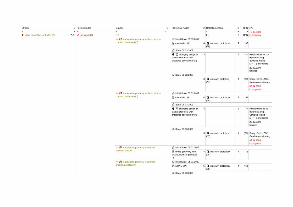
>> inadequate geometry to clamp wire to contact pin chosen {1}
Initial State: 05.03.2009
calculation {6} 4 tests with prototypes {28}
7 196
State: 05.03.2009
changing design of clamp after tests with prototype at customer {1}
3 7 147 Responsible for co-mponent: plug:Schranz, Franz,D-PT, Entwicklung
20.02.2009finished
State: 05.03.2009
3 tests with prototype {17}
4 (84) Santy, David, ZQS,Qualitätsentwicklung
02.04.2009in progress
>> inadequate geometry to connect isolation chosen {1}
Initial State: 05.03.2009
reuse geometry from previous/similar products {3}
4 tests with prototypes {28}
4 112
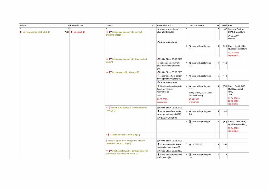
>> inadequate geometry to connect shielding chosen {1}
Initial State: 05.03.2009
NONE {27} 6 tests with prototypes {28}
4 168
State: 05.03.2009
Effects S Failure Modes Causes C Preventive Action O Detection Action D RPN R/D
^ drive cannot be controlled {2}
^7 (7)
^ no signal {2}
^>> inadequate geometry to connect shielding chosen {1}
^ change shielding of plug after tests {2}
3 7 147 Seetzen, Gudrun,D-PT, Entwicklung
20.02.2009finished
State: 05.03.2009
3 tests with prototype {17}
3 (63) Santy, David, ZQS,Qualitätsentwicklung
02.04.2009in progress
>> inadequate geometry to fixate contact pins {1}
Initial State: 05.03.2009
reuse geometry from previous/similar products {3}
4 tests with prototypes {28}
4 112
>> inadequate solder chosen {2} Initial State: 05.03.2009
experience from earlier development projects {16}
4 tests with prototypes {28}
5 140
State: 05.03.2009
life-time simulation with focus on vibration resistance {8}
Trial
25.06.2009in progress
4 tests with prototype {17}
Santy, David, ZQS, Quali-tätsentwicklung
02.04.2009in progress
3 (84) Santy, David, ZQS,Qualitätsentwick-lung,Trial
02.04.2009 -25.06.2009in progress
>> internal resistance of chosen solder is too high {2}
Initial State: 05.03.2009
experience from earlier development projects {16}
4 tests with prototypes {28}
5 140
State: 05.03.2009
4 tests with prototype {17}
3 (84) Santy, David, ZQS,Qualitätsentwicklung
02.04.2009in progress
> isolation detaches from plug {1}
loss of signal level through the interface between cable and plug {2}
Initial State: 05.03.2009
simulation under knownapplication conditions {3}
5 NONE {29} 10 350
>> mechanical layout of contacts does not correspond with electrical layout {1}
Initial State: 05.03.2009
verify measurements in CAD layout {2}
4 tests with prototypes {28}
4 112

Effects S Failure Modes Causes C Preventive Action O Detection Action D RPN R/D
^ drive cannot be controlled {2}
^7 (7)
^ no signal {2}
no or no safe electrical connection between cable and plug {2}
Initial State: 05.03.2009
NONE {27} 5 NONE {29} 10 350
> plug-connection unintentionally falls apart {1}
> reduced fixation after soldering with increased temperature {1}
> shielding detaches from plug {1}
> shielding is interrupted between plug and socket {1}
> single wires detach from plug {1}
>> snap-in is too weak {1} Initial State: 05.03.2009
calculation {6} 4 tests with prototypes {28}
7 196
State: 05.03.2009
changing snap-in after tests with prototype at customer {1}
3 7 147 Responsible for co-mponent: plug:Schranz, Franz,D-PT, Entwicklung
20.02.2009finished
State: 05.03.2009
3 tests with prototype {17}
4 (84) Santy, David, ZQS,Qualitätsentwicklung
02.04.2009in progress
> unsufficient mechanical fixation of contact pins {1}
>> unsuitable material for plug body chosen {1}
Initial State: 05.03.2009
experience from earlier development projects {16}
3 material test with plate sample {5}
3 63
>> unsuitable material for plug body chosen {1}
Initial State: 05.03.2009
experience from earlier development projects {16}
3 material test with plate sample {5}
3 63
>> unsuitable material for shielding of plug chosen {1}
Initial State: 05.03.2009
experience from earlier development projects {16}
3 tests with prototypes {28}
6 126
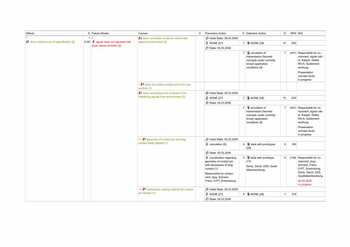
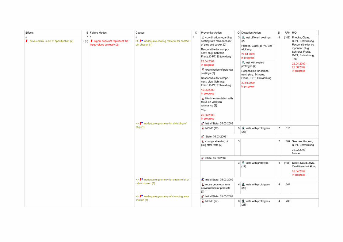
drive control is out of specification {2} 9 (9) signal does not represent the input values correctly {2}
> ambiguous pluggable connection {1}

Effects S Failure Modes Causes C Preventive Action O Detection Action D RPN R/D
^ drive control is out of specification {2}
^9 (9)
^ signal does not represent the
input values correctly {2}
>> coating material not suitable for core material of pin and plug contact {1}
Initial State: 05.03.2009
experience from earlier development projects {16}
7 NONE {29} 10 630
State: 05.03.2009
coordination regarding coating with manufacturer of pins and socket {2}
Responsible for compo-nent: plug: Schranz,Franz, D-PT, Entwicklung
3 test different coatings {2}
Priebke, Claas, D-PT, Ent-wicklung
test with coated prototype {2}
Responsible for compo-nent: plug: Schranz,Franz, D-PT, Entwicklung
4 (108) Priebke, Claas,D-PT, Entwicklung,Responsible for co-mponent: plug:Schranz, Franz,D-PT, Entwicklung
22.04.2009in progress
>> coding of plug is missing or does not fit into socket {1}
Initial State: 05.03.2009
verify measurements in CAD layout {2}
4 tests with prototypes {28}
4 144
> contact force between wire and contact is not sufficient {1}
>> degree of waste is too high {2} Initial State: 05.03.2009
experience from earlier development projects {16}
4 tests with prototypes {28}
5 180
State: 05.03.2009
life-time simulation with focus on vibration resistance {8}
Trial
25.06.2009in progress
4 tests with prototype {17}
Santy, David, ZQS, Quali-tätsentwicklung
02.04.2009in progress
3 (108) Santy, David, ZQS,Qualitätsentwick-lung,Trial
02.04.2009 -25.06.2009in progress
distortion of signal through the interface between cable and plug {2}
Initial State: 05.03.2009
NONE {27} 7 NONE {29} 10 630
State: 05.03.2009
7 simulation of transmission (favored concept) under currently known application conditions {9}
7 (441) Responsible for co-mponent: signal cab-le: Kasper, Detlef,RD-S, Systement-wicklung
22.09.2009in progress
> does not appropriately seal towards cable isolation {1}
Effects S Failure Modes Causes C Preventive Action O Detection Action D RPN R/D
^ drive control is out of specification {2}
^9 (9)
^ signal does not represent the
input values correctly {2}
does not isolate conductor electrically against environment {2}
Initial State: 05.03.2009
NONE {27} 7 NONE {29} 10 630
State: 05.03.2009
7 simulation of transmission (favored concept) under currently known application conditions {9}
7 (441) Responsible for co-mponent: signal cab-le: Kasper, Detlef,RD-S, Systement-wicklung
Presentationconcept studyin progress
> does not isolate contact pins from one another {1}
does not proctect the conductor from interfering signals from environment {2}
Initial State: 05.03.2009
NONE {27} 7 NONE {29} 10 630
State: 05.03.2009
7 simulation of transmission (favored concept) under currently known application conditions {9}
7 (441) Responsible for co-mponent: signal cab-le: Kasper, Detlef,RD-S, Systement-wicklung
Presentationconcept studyin progress
>> geometry of contact pin and plug contact badly aligned {1}
Initial State: 05.03.2009
calculation {6} 4 tests with prototypes {28}
5 180
State: 05.03.2009
coordination regarding geometry of contact pin with developers of plug contact {1}
Responsible for compo-nent: plug: Schranz,Franz, D-PT, Entwicklung
3 tests with prototype {17}
Santy, David, ZQS, Quali-tätsentwicklung
4 (108) Responsible for co-mponent: plug:Schranz, Franz,D-PT, Entwicklung,Santy, David, ZQS,Qualitätsentwicklung
02.04.2009in progress
>> inadequate coating material for contact pin chosen {1}
Initial State: 05.03.2009
NONE {27} 5 NONE {29} 7 315
State: 05.03.2009
Effects S Failure Modes Causes C Preventive Action O Detection Action D RPN R/D
^ drive control is out of specification {2}
^9 (9)
^ signal does not represent the
input values correctly {2}
^>> inadequate coating material for contact pin chosen {1}
^ coordination regarding coating with manufacturer of pins and socket {2}
Responsible for compo-nent: plug: Schranz,Franz, D-PT, Entwicklung
22.04.2009in progress
examination of potentialcoatings {2}
Responsible for compo-nent: plug: Schranz,Franz, D-PT, Entwicklung
15.05.2009in progress
life-time simulation with focus on vibration resistance {8}
Trial
25.06.2009in progress
3 test different coatings {2}
Priebke, Claas, D-PT, Ent-wicklung
22.04.2009in progress
test with coated prototype {2}
Responsible for compo-nent: plug: Schranz,Franz, D-PT, Entwicklung
22.04.2009in progress
4 (108) Priebke, Claas,D-PT, Entwicklung,Responsible for co-mponent: plug:Schranz, Franz,D-PT, Entwicklung,Trial
22.04.2009 -25.06.2009in progress
>> inadequate geometry for shielding of plug {1}
Initial State: 05.03.2009
NONE {27} 5 tests with prototypes {28}
7 315
State: 05.03.2009
change shielding of plug after tests {2}
3 7 189 Seetzen, Gudrun,D-PT, Entwicklung
20.02.2009finished
State: 05.03.2009
3 tests with prototype {17}
4 (108) Santy, David, ZQS,Qualitätsentwicklung
02.04.2009in progress
>> inadequate geometry for strain-relief of cable chosen {1}
Initial State: 05.03.2009
reuse geometry from previous/similar products {3}
4 tests with prototypes {28}
4 144
>> inadequate geometry of clamping area chosen {1}
Initial State: 05.03.2009
NONE {27} 8 tests with prototypes {28}
4 288

Effects S Failure Modes Causes C Preventive Action O Detection Action D RPN R/D
^ drive control is out of specification {2}
^9 (9)
^ signal does not represent the
input values correctly {2}
^>> inadequate geometry of clamping area chosen {1}
^ State: 05.03.2009
change geometry of clamping area after tests with prototype {1}
4 RPN Responsible for co-mponent: plug:Schranz, Franz,D-PT, Entwicklung
12.05.2009finished
State: 05.03.2009
tests with prototype {17}
3 RPN Santy, David, ZQS,Qualitätsentwicklung
12.05.2009in progress
>> inadequate geometry to clamp wire to contact pin chosen {1}
Initial State: 05.03.2009
calculation {6} 4 tests with prototypes {28}
7 252
State: 05.03.2009
changing design of clamp after tests with prototype at customer {1}
3 7 189 Responsible for co-mponent: plug:Schranz, Franz,D-PT, Entwicklung
20.02.2009finished
State: 05.03.2009
3 tests with prototype {17}
4 (108) Santy, David, ZQS,Qualitätsentwicklung
02.04.2009in progress
>> inadequate geometry to connect isolation chosen {1}
Initial State: 05.03.2009
reuse geometry from previous/similar products {3}
4 tests with prototypes {28}
4 144
>> inadequate geometry to connect shielding chosen {1}
Initial State: 05.03.2009
NONE {27} 6 tests with prototypes {28}
4 216
State: 05.03.2009
change shielding of plug after tests {2}
3 7 189 Seetzen, Gudrun,D-PT, Entwicklung
20.02.2009finished
State: 05.03.2009

Effects S Failure Modes Causes C Preventive Action O Detection Action D RPN R/D
^ drive control is out of specification {2}
^9 (9)
^ signal does not represent the
input values correctly {2}
^>> inadequate geometry to connect shielding chosen {1}
^ 3 tests with prototype {17}
3 (81) Santy, David, ZQS,Qualitätsentwicklung
02.04.2009in progress
>> inadequate solder chosen {2} Initial State: 05.03.2009
experience from earlier development projects {16}
4 tests with prototypes {28}
5 180
State: 05.03.2009
life-time simulation with focus on vibration resistance {8}
Trial
25.06.2009in progress
4 tests with prototype {17}
Santy, David, ZQS, Quali-tätsentwicklung
02.04.2009in progress
3 (108) Santy, David, ZQS,Qualitätsentwick-lung,Trial
02.04.2009 -25.06.2009in progress
> incomplete assignment of wires to contact pins {1}
> isolation detaches from plug {1}
>> mechanical layout of contacts does not correspond with electrical layout {1}
Initial State: 05.03.2009
verify measurements in CAD layout {2}
4 tests with prototypes {28}
4 144
> modulation of signal changes during transmission within the given application conditions {4}
Initial State: 17.01.2006
NONE {27} 7 NONE {29} 10 630
State: 17.01.2006
7 simulation of transmission (favored concept) under currently known application conditions {9}
7 (441) Responsible for co-mponent: signal cab-le: Kasper, Detlef,RD-S, Systement-wicklung
22.09.2009in progress
modulation of signal changes during transmission within the given application conditions {4}
Initial State: 05.03.2009
NONE {27} 7 NONE {29} 10 630
State: 05.03.2009
7 simulation of transmission (favored concept) under currently known application conditions {9}
7 (441) Responsible for co-mponent: signal cab-le: Kasper, Detlef,RD-S, Systement-wicklung
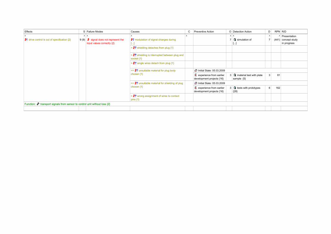
Effects S Failure Modes Causes C Preventive Action O Detection Action D RPN R/D
^ drive control is out of specification {2}
^9 (9)
^ signal does not represent the
input values correctly {2}
^ modulation of signal changes during
[...]
^ ^7
^ simulation of
[...]
^7
^(441)
Presentationconcept studyin progress
> shielding detaches from plug {1}
> shielding is interrupted between plug and socket {1}
> single wires detach from plug {1}
>> unsuitable material for plug body chosen {1}
Initial State: 05.03.2009
experience from earlier development projects {16}
3 material test with plate sample {5}
3 81
>> unsuitable material for shielding of plug chosen {1}
Initial State: 05.03.2009
experience from earlier development projects {16}
3 tests with prototypes {28}
6 162
> wrong assignment of wires to contact pins {1}
Function: transport signals from sensor to control unit without loss {2}

1.2.atransport signals from receiver to control unit without loss {1}
1.2.1.atransmit signal with specified modulation {3}
1.2.1.cisolate conductor electrically against environment {1}
1.2.1.dprotect conductor from environmental influences {1}
1.2.1.eproctect conductor from interfering signals of the
environment {1}
3.bis electrical interface between cable and plug {2}
3.1.atransmit signal with specified modulation {3}
3.1.1.bcoating {1}
3.1.1.csize of contact area respectively overlapping of plug
contact with contact pin {1}
3.1.1.esoldering area of conductor {1}
3.2.adefines an assignment of connector pins to wires {1}
3.2.1.alayout of contacts {1}
3.2.cisolate contact pins electrically from one another {1}
3.2.1.alayout of contacts {1}
3.2.1.cmaterial of plug body {1}
3.2.1.igeometry to connect isolation {1}
3.2.eappropriate sealing towards cable isolation {1}
3.2.1.igeometry to connect isolation {1}
3.2.felectically connect cable shielding with plug shielding and
socket shielding {1}
3.2.1.cmaterial of plug body {1}
3.2.1.fgeometry of plug-shielding {1}
3.2.1.jgeometry to connect shielding {1}
3.2.1.gmaterial of plug-shielding {1}
3.2.gmechanically fixates cabel, shielding, isolation and plug
body against one another {1}
3.2.1.cmaterial of plug body {1}
3.2.1.hgeometry of strain-relief for cable {1}
3.2.1.igeometry to connect isolation {1}
3.2.1.jgeometry to connect shielding {1}
3.3.bhas required electrical properties {2}
3.3.1.asoldering material {2}
3.1.1.bcoating {1}
3.1.1.csize of contact area respectively overlapping of plug
contact with contact pin {1}
3.1.1.esoldering area of conductor {1}
3.3.ahas specified mechanical stability {3}
3.1.1.acore material contact pin {1}
3.1.1.dcross section and radial geometry of contact {1}
3.1.1.esoldering area of conductor {1}
3.3.1.asoldering material {2}
2.1.1.1.1.aconductor material {1}
3.1.1.bcoating {1}
3.2.iclamp wires to contact pin with sufficent contact force {1}
3.2.1.cmaterial of plug body {1}
3.2.1.kgeometry to clamp wires to contact pin {1}
1.acontrol propulsion according to specification {2}
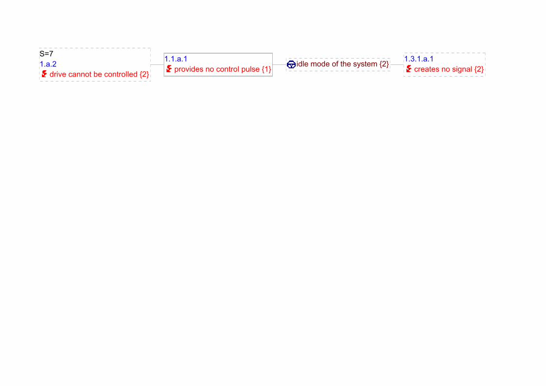
1.1.a.1provides no control pulse {1}
idle mode of the system {2} 1.3.1.a.1creates no signal {2}
S=71.a.2
drive cannot be controlled {2}
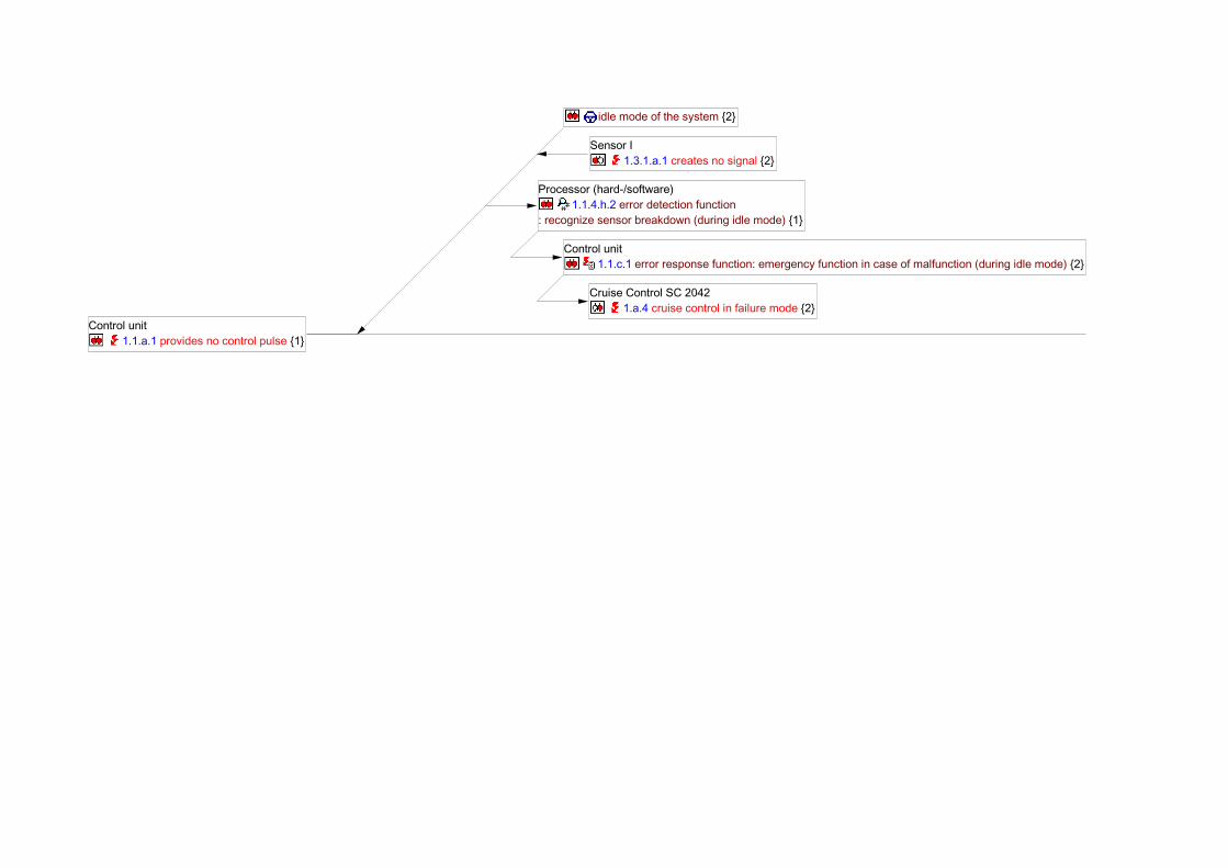
Control unit 1.1.a.1 provides no control pulse {1}
idle mode of the system {2}
Sensor I 1.3.1.a.1 creates no signal {2}
Processor (hard-/software) 1.1.4.h.2 error detection function
: recognize sensor breakdown (during idle mode) {1}
Control unit 1.1.c.1 error response function: emergency function in case of malfunction (during idle mode) {2}
Cruise Control SC 2042 1.a.4 cruise control in failure mode {2}
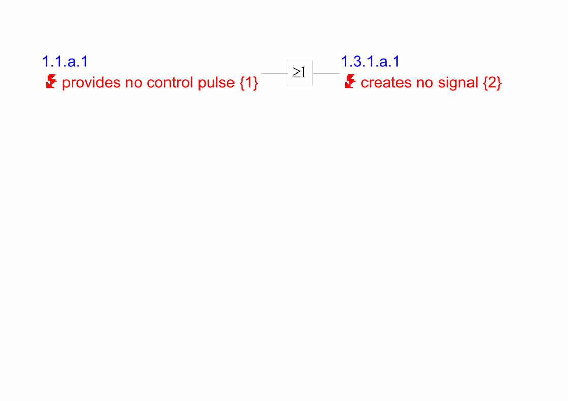
1.1.a.1provides no control pulse {1} ³1
1.3.1.a.1creates no signal {2}

1/3
Process Flow Diagram
Program:Assembly signal cable (complete)
Part number/Latest Change Level:315-81.10, 315-81.30, 315-81.40, 315-81.50,315-81.70, 315-81.80, 315-81.60, 315-81.20
Part Description:soldering process - cable to plug
Revision Level:Version 1.2 a
Revised by:Priebke, Claas, D-PT; Hehre, Claudia, FV-PO; Peach,Marcel, FV-PO
Created:06.03.2006
Modified:07.04.2009
Page:
Symbol Reference Symbol Reference Symbol Reference Part/P-rocess Num-ber
Process Na-me/OperationDescription
No. Product Characte-ristics
Clas-s.
No. Process Charac-teristics
Clas-s.
1/3
4.1Prepareworkplace
4.1 Prepare workplace
4.1.a type of cable
4.1.b type of plug
4.2Insert pluginto solderingappliance
4.2 Insert pluginto soldering appliance
4.3Solder cablestrands onplug pins (ma-nually)
4.4Solder shiel-ding on plughousing (onesided; ma-nually)
4.3 Solder cable strands on plug pins (manually)
4.3.b assignment of pins to cable strands
CC
4.3.c pull-off strength
4.3.d volume resistance
CC
4.3.1.-a
soldering temperature
CC
4.3.2.c color coding in soldering appliance
4.3.3.-a
temperature of soldering iron tip

Symbol Reference Symbol Reference Symbol Reference Part/P-rocess Num-ber
Process Na-me/OperationDescription
No. Product Characte-ristics
Clas-s.
No. Process Charac-teristics
Clas-s.
^ ^4.3Solder cablestrands on[...]
^ ^4.4Solder shielding on plug[...]
^ ^ 4.4 Solder shielding on plug housing (one sided; manually)
4.4.c pull-off strength
4.4.1.-a
soldering temperature
CC
4.4.3.-a
temperature of soldering iron tip
4.5Put cable intostrain-relief
4.5 Put cable into strain-relief
4.5.b pull-off strenght
4.6Test cableusing cabletest appliance
4.6 Test cableusing cable test appliance
4.6.1.-b
start test-sequence, withdraw cable and sort out faulty cables
4.6.2.-b
perform test-cycle according to test description, write test protocol
4.8Corrective sol-dering offaulty parts
4.8 Corrective soldering of faultyparts
4.8.b assignment of pins to cable strands
4.8.c pull-off strength
4.8.d volume resistance
CC
4.8.1.-a
soldering temperature
CC
4.8.2.-b
color coding in soldering appliance
4.8.3.-a
temperature of soldering iron tip

Symbol Reference Symbol Reference Symbol Reference Part/P-rocess Num-ber
Process Na-me/OperationDescription
No. Product Characte-ristics
Clas-s.
No. Process Charac-teristics
Clas-s.
4.7Attachproof-of-te-sting label tocable and putcable intotransport bin
4.7 Attach proof-of-testing label to cable and put cable into transport bin
4.7.a proof-of-testing label attached to good cables

Control Plan
Prototype: Prelaunch: Production: X
Control Plan Number:CP 001-2.1
Part number/Latest Change Level:2.1, 3.
Part Name/Description:Electric conductor
Supplier/Plant:APS
Supplier Code:123-654-890
Key Contact/Phone:Seetzen, Gudrun, D-PT, Entwicklung
Core Team:Seetzen, Gudrun, D-PT, Entwicklung; Schranz, Franz, D-PT, Entwick-lung; Santy, David, ZQS, Qualitätsentwicklung
Supplier/Plant Approval/Date:APS, KGW
Date/Other Approval (if req'd):31.11.2006
Created:17.03.2006
Modified:07.04.2009
Customer Engineering Approval/Date (if req'd):Nicht erforderlich
Customer Quality Approval/Date (if req'd):Nicht erforderlich
Date/Other Approval (if req'd):Nicht erforderlich
Part/Proc-ess Num-ber
Process Name/Ope-ration Description
Machine, Device,Jig, Tools for Mfg.
Characteristics
No. Product Characteri-stics
Process Characteri-stics
Clas-sifica-tion
Methods
Specification Inspection Equip-ment/Measure-ment Technique
Sample
Size Freq.
Control Method
Reaction Plan
2.1.1.1 conductor
Change of soldering material from Pb60Sn40 to SnCu99C by requirements of RoHS since 07/2006.Increased soldering temperature (> 220 °C) with changed soldering material!
2.1.1.-1.b
transmission of signal through voltage level
32 Ns ±1 NONE simulation under known application conditions
2.1.1.-1.c
transmission of signal through modulation
11 Ns NONE NONE
2.1.1.-1.d
mechanical stability of conductor
37,2 MPa NONE NONE
2.1.1.2 Isolation 2.1.1.-2.a
dielectric strength
NONE NONE
2.1.1.-2.b
long-term stability considering all application conditions
NONE NONE
2.1.1.3 Shielding 2.1.1.-3.b
sensitivity against interferencesof signal transmission (both level and modulation)
NONE NONE

Part/Proc-ess Num-ber
Process Name/Ope-ration Description
Machine, Device,Jig, Tools for Mfg.
Characteristics
No. Product Characteri-stics
Process Characteri-stics
Clas-sifica-tion
Methods
Specification Inspection Equip-ment/Measure-ment Technique
Sample
Size Freq.
Control Method
Reaction Plan
^2.1.1.3
Change of soldering material from Pb60Sn40 to SnCu99C by requirements of RoHS since 07/2006.Increased soldering temperature (> 220 °C) with changed soldering material!
^2.1.1.3.b
^ sensitivity
against interferencesof signal transmission (both level and modulation)
^ ^ NONE
^ NONE
3.1 Contact pin
Change of soldering material from Pb60Sn40 to SnCu99C by requirements of RoHS since 07/2006.Increased soldering temperature (> 220 °C) with changed soldering material!
3.2 Plug body
Change of soldering material from Pb60Sn40 to SnCu99C by requirements of RoHS since 07/2006.Increased soldering temperature (> 220 °C) with changed soldering material!
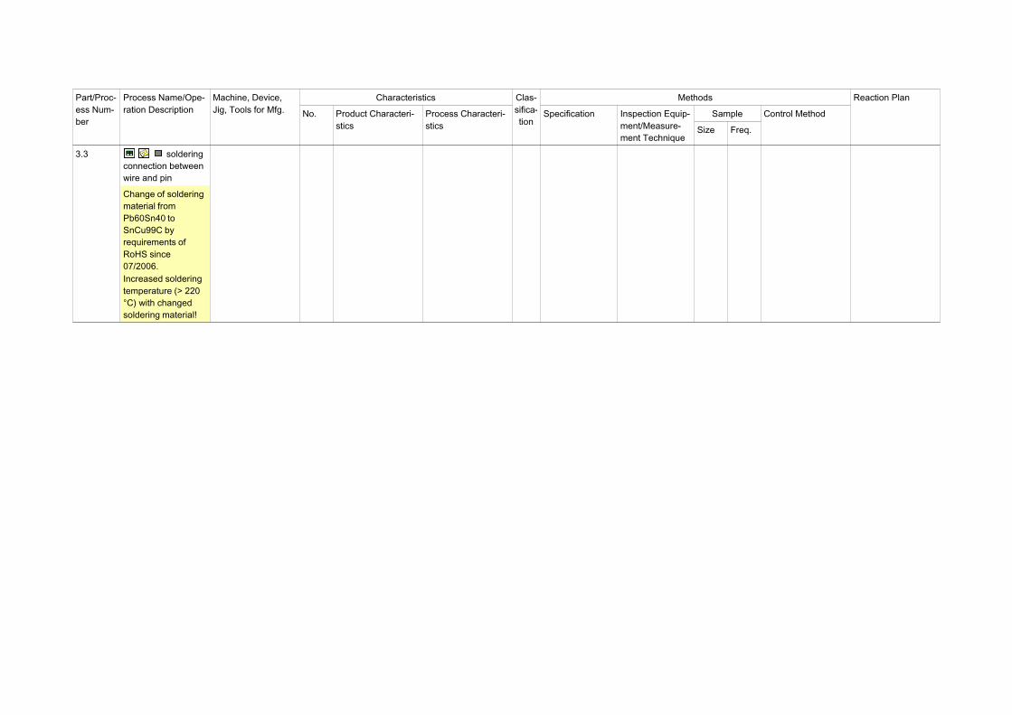
Part/Proc-ess Num-ber
Process Name/Ope-ration Description
Machine, Device,Jig, Tools for Mfg.
Characteristics
No. Product Characteri-stics
Process Characteri-stics
Clas-sifica-tion
Methods
Specification Inspection Equip-ment/Measure-ment Technique
Sample
Size Freq.
Control Method
Reaction Plan
3.3 soldering connection between wire and pin
Change of soldering material from Pb60Sn40 to SnCu99C by requirements of RoHS since 07/2006.Increased soldering temperature (> 220 °C) with changed soldering material!