table of contents - baffinland · 10.2 baffinland spill equipment ... onboard sopep equipment and...
TRANSCRIPT


Spill at Sea Response Plan Issue Date: August 7, 2015
Rev.: 0
Page 3 of 140
Site Wide Document #: BAF-PH1-830-P16-0042
The information contained herein is proprietary to Baffinland Iron Mines Corporation and is used solely for the purpose for which it is supplied. It shall not be disclosed in whole or in part, to any other party, without the express permission in writing by Baffinland Iron Mines Corporation.
Note: This is an UNCONTROLLED COPY. All staff members are responsible to ensure the latest revision is used.
TABLE OF CONTENTS
Purpose of the Spill at Sea Response Plan (SSRP) .................................................................... 9
Use of the SSRP ................................................................................................................... 10
Preparedness and Response Framework for Spill at Sea ....................................................... 10
General Overview ................................................................................................................ 11
Context for the SSRP ............................................................................................................ 12
1 Approach to Spill at Sea Response Plan .......................................................................... 14
2 Organizational Structure for Emergency Response ......................................................... 15
2.1 BIMC Site Wide Emergency response .................................................................................. 15
2.1.1 BIMC Emergency Response Team (ERT) ............................................................................... 16
2.1.2 Emergency Management Team ............................................................................................ 16
2.1.3 Corporate Emergency Management Team ........................................................................... 18
3 Spill at Sea Response ..................................................................................................... 18
3.1 Tier 1 Responder - Vessel Master and Crew ......................................................................... 18
3.2 Tier 2 Responder – Vessel and BIMC EMT ............................................................................ 18
3.3 Tier 3 Responder – Vessel, BIMC and OSRL .......................................................................... 18
4 Action Checklists for key emergency response team personnel ....................................... 19
4.1 Ship Operator – Tier 1 Responder ........................................................................................ 19
4.2 Spill Observer (Vessel Crew) ................................................................................................ 19
4.3 Vessel Master ..................................................................................................................... 20
4.4 BIMC Emergency Response Team (ERT) – Tier 2 Responder .................................................. 21
4.4.1 Incident Commander (IC) – ERT Trainer ................................................................................ 21
4.5 Emergency Management Team ........................................................................................... 22
4.5.1 Emergency Management Team Leader - MFSO ................................................................... 22
4.5.2 Environmental Planning Team Leader (Environmental Manager or designate at Site) ........ 24
4.5.3 Logistics Team Leader (Port Logistics manager or designate) .............................................. 25
4.5.4 Health and Safety Team Lead (Member of the ERT) ............................................................. 26
5 Alert Procedure, Initial Actions and Notifications ........................................................... 27
5.1 Initial Actions ..................................................................................................................... 27
6 Spill Assessment ............................................................................................................ 29

Spill at Sea Response Plan Issue Date: August 7, 2015
Rev.: 0
Page 4 of 140
Site Wide Document #: BAF-PH1-830-P16-0042
The information contained herein is proprietary to Baffinland Iron Mines Corporation and is used solely for the purpose for which it is supplied. It shall not be disclosed in whole or in part, to any other party, without the express permission in writing by Baffinland Iron Mines Corporation.
Note: This is an UNCONTROLLED COPY. All staff members are responsible to ensure the latest revision is used.
6.1 Spill Assessment Tier Level .................................................................................................. 29
7 Constraint – Extreme weather Conditions ...................................................................... 31
7.1 Tier 2 Response during Ice Melt (July) ................................................................................. 31
7.2 Tier 2 Response during Freeze-up (October) ........................................................................ 31
7.3 Tier 2 Response during Ice Covered Period (end of October to mid-July) .............................. 31
8 Response Technique Selection ....................................................................................... 33
8.1 Response Technique Decision Flowchart ............................................................................. 34
9 Waste Management ..................................................................................................... 35
10 Spill Response Resources ............................................................................................ 36
10.1 Ship Response Equipment (Tier 1 Capability – SOPEP Resources) ...................................... 36
10.2 Baffinland Spill Equipment (Tier 2 Capability) ................................................................... 37
10.2.1 Milne Port Resources ............................................................................................................ 37
10.2.2 BIMC Response Times ........................................................................................................... 41
10.3 Tier 3 Arrangements ........................................................................................................ 42
10.3.1 OSRL ...................................................................................................................................... 42
10.3.2 Additional Tier 3 Resources ................................................................................................... 45
10.4 Additional Assistance Agreement .................................................................................... 46
Reference Information .................................................................................................................. 47
11 Fuel Characteristics .................................................................................................... 47
11.1 Fuel Characteristics in Cold Marine Environments ............................................................ 50
11.1.1 Fuel Properties ...................................................................................................................... 50
11.1.2 Spill Fate and Behaviour in Cold Marine Environments ........................................................ 51
11.1.3 The Weathering Process ....................................................................................................... 51
12 Mitigation Measures .................................................................................................. 54
13 Historic Spill Data ....................................................................................................... 54
13.1 Quantities of spills ........................................................................................................... 54
13.2 Causes of spills ................................................................................................................ 55
14 Key Canadian Arctic Stakeholders ............................................................................... 57
14.1 The Canadian Coast Guard ............................................................................................... 57
14.2 Environment Canada Science Table .................................................................................. 57

Spill at Sea Response Plan Issue Date: August 7, 2015
Rev.: 0
Page 5 of 140
Site Wide Document #: BAF-PH1-830-P16-0042
The information contained herein is proprietary to Baffinland Iron Mines Corporation and is used solely for the purpose for which it is supplied. It shall not be disclosed in whole or in part, to any other party, without the express permission in writing by Baffinland Iron Mines Corporation.
Note: This is an UNCONTROLLED COPY. All staff members are responsible to ensure the latest revision is used.
14.3 Transport Canada ............................................................................................................ 57
14.4 Government of Nunavut .................................................................................................. 57
15 Fuel Spill Risk Assessment ........................................................................................... 59
15.1 Risk Assessment Methodology ........................................................................................ 59
15.2 Risk Register ................................................................................................................... 62
15.3 Risk Assessment Matrix ................................................................................................... 69
Table of Tables Table 5-1 Notifications ................................................................................................................................ 28
Table 10-1 – Onboard SOPEP Equipment and Materils .............................................................................. 36
Table 10-2 Tier 2 Capability ........................................................................................................................ 37
Table 10-3 OSRL Service Level Agreement Summary ................................................................................. 42
Table 10-4: Wildlife emergency contacts ................................................................................................... 45
Table 11-1 Fuel inventory ........................................................................................................................... 47
Table 11-2: Location-specific weathering of fuel. ....................................................................................... 52
Table 15-1 Definition of Consequence Categories ..................................................................................... 60
Table 15-2 Definition of Likelihood Categories ........................................................................................... 61
Table 15-3: Vessels ...................................................................................................................................... 62
Table 15-4 Risk Assessment Matrix ............................................................................................................ 69
Table of Figures Figure 1-1: Shipping route from Milne Port to Rotterdam ......................................................................... 11
Figure 1-2 – Northern Shipping route from Baffin Bay to Milne Port ........................................................ 12
Figure 2-1: BIMC Emergency Response Management structure ................................................................ 15
Figure 5-1 Initail Actions ............................................................................................................................. 27
Figure 6-1 Tier Level assessment chart ....................................................................................................... 30
Figure 8-1 Response Technique decision flow chart .................................................................................. 34
Figure 10-1 Logistics Responsibility ............................................................................................................ 44
Figure 11-1 Classification of Oil According to Specific Gravity ................................................................... 51
Figure 11-2: Weathering of fuel spilled in the marine environment. ......................................................... 52
Figure 11-3: Effect of cold temperatures on the weathering of fuel. ......................................................... 53
Figure 11-4: Potential fates of fuel spilled in cold marine environments................................................... 53
Figure 13-1: Seaborne trade and number of tanker spills >7 tonnes, 1970 to 2011. Source: ITOPF, 2012 54
Figure 13-2: Spills >7 tonnes per decade showing the influence of a relatively small number of large spills
on the overall figure (ITOPF, 2012) ............................................................................................................. 55
Figure 13-3: Incidence of spills <7 tonnes by operation at time of incident, 1974-2012 ........................... 55
Figure 13-4: Incidence of spills 7-700 tonnes by operation at time of incident, 1970-2012 ..................... 56

Spill at Sea Response Plan Issue Date: August 7, 2015
Rev.: 0
Page 6 of 140
Site Wide Document #: BAF-PH1-830-P16-0042
The information contained herein is proprietary to Baffinland Iron Mines Corporation and is used solely for the purpose for which it is supplied. It shall not be disclosed in whole or in part, to any other party, without the express permission in writing by Baffinland Iron Mines Corporation.
Note: This is an UNCONTROLLED COPY. All staff members are responsible to ensure the latest revision is used.
Figure 13-5: Incidence of spills >700 tonnes by cause, 1970-2012 ............................................................ 56
Figure 13-6: Incidence of spills >700 tonnes by operation at time of incident, 1970-2012 ...................... 56

Spill at Sea Response Plan Issue Date: August 7, 2015
Rev.: 0
Page 7 of 140
Site Wide Document #: BAF-PH1-830-P16-0042
The information contained herein is proprietary to Baffinland Iron Mines Corporation and is used solely for the purpose for which it is supplied. It shall not be disclosed in whole or in part, to any other party, without the express permission in writing by Baffinland Iron Mines Corporation.
Note: This is an UNCONTROLLED COPY. All staff members are responsible to ensure the latest revision is used.
Table A: Distribution List for the SSRP
Department of Environment - Environmental Protection
Division
PO Box 1000 Station 1300
Iqaluit, NU, Canada
X0A 0H0
Tel: (867) 975-7700, 1-866-222-9063
Fax: (867) 975-7742
Department of Fisheries and Oceans - Central and Arctic
Region
520 Exmouth Street
Sarnia, ON
N7T 8B1
Tel: (519) 383-1813, (866) 290-3731
Fax: (519) 464-5128
Qikiqtani Inuit Association
Igluvut Building, 2nd floor
PO Box 1340
Iqaluit, NU
X0A 0H0
Tel: (867) 975-8400, 1-800-667-2742
Fax: (867) 979-3238
AANDC - Nunavut Regional Office
Qimugjuk Building
PO Box 2200
Iqaluit, NU
X0A 0H0
Tel: (867) 975-4500
Fax: (867) 975-4560
AANDC - Water Resources Division
Qimugjuk Building
PO Box 100
Iqaluit, NU
X0A 0H0
Tel: (867) 975-4550 (Water Resources Manager)
Fax: (867) 975-4560
Mittimatalik Hunters and Trappers Organization
PO Box 189
Pond Inlet, NU, Canada
X0A 0S0
Tel: (867) 899-8856
Fax: (867) 899-8095
Nunavut Impact Review Board
PO Box 1360
Cambridge Bay, NU, Canada
X0B 0C0
Tel: (867) 983-2574, 1-866-233-3033
Fax: (867) 983-2594
Nunavut Water Board
PO Box 119
Gjoa Haven, NU, Canada
X0B 1J0
Tel: (867) 360-6338
Fax: (867) 360-6369
Hamlet of Pond Inlet
(867) 899-8934
Hamlet of Hall Beach
(867) 928-8829 ext 211
Hamlet of Cape Dorset
(867) 897-8943
Hamlet of Arctic Bay
(867) 439-9917
Hamlet of Igloolik
(867) 934-8940
Hamlet of Clyde River
(867) 924-6220
Hamlet of Kimmirut
(867) 939-2247

Spill at Sea Response Plan Issue Date: August 7, 2015
Rev.: 0
Page 8 of 140
Site Wide Document #: BAF-PH1-830-P16-0042
The information contained herein is proprietary to Baffinland Iron Mines Corporation and is used solely for the purpose for which it is supplied. It shall not be disclosed in whole or in part, to any other party, without the express permission in writing by Baffinland Iron Mines Corporation.
Note: This is an UNCONTROLLED COPY. All staff members are responsible to ensure the latest revision is used.
Acronyms
ACS Alaskan Clean Seas MARPOL International Convention for the Prevention of Pollution from Ships
AMOSC Australia Marine Oil Spill Centre MPC Milne Port Control
AWPPA Arctic Water Pollution Prevention Act MRT Mine Rescue Team
BAOAC Bonn Agreement Oil Appearance Code MSC Mine site complex
BIM Baffinland Iron Mines Corporation MSRC Marine Spill Response Corporation
CCG Canadian Coast Guard NIRB Nunavut Impact Review Board
CEMT Corporate Emergency Management
Team
NOAA National Oceanic and Atmospheric Administration
CLC Compensation and Liability
Conventions
OPEP Oil Pollution Emergency Plan
CMP Crisis Management Plan OPRC International Convention on Oil Pollution Preparedness, Response
and Co-operation
CSA Canada Shipping Act OSCAR Oil Spill Contingency And Response Model
DWT Dead Weight Tonnage SSRP Spill at Sea Response Plan
EC Environment Canada OSIS Oil Spill Information System Model
ECRC Eastern Canada Response Corporation OSRL Oil Spill Response Limited
EMT Emergency Management Team PPE Personal Protective Equipment
EMTL Emergency Management Team Lead PSC Port site complex
EPB Environment Protection Board RAM Risk Assessment Matrix
ER Emergency Response SAF Sea Alarm Foundation
ERP Emergency Response Plan SAR Search And Rescue
FLIR Forward Looking Infrared Radar SCAT Shoreline Cleanup Assessment Technique
GIS Global Information System SCP Spill Contingency Plan
GPR Ground Penetrating Radar SG Specific Gravity
GPS Global Positioning System SLA Service Level Agreement
GRN Global Response Network SLAR Side-Looking Airborne Radar
IC Incident Commander SMS Safety Management System
ICC Incident Command Centre SOPEP Shipboard Oil Pollution Plan
IFO Intermediate Fuel Oil SOS Shoreline Oiling Summary
IMO International Maritime Organisation USCG United State Coast Guard
IPIECA International Petroleum Industry
Environmental Conservation
Association
WCMRC Western Canada Marine Response Corporation
ITOPF International Tanker Owners Pollution
Federation
YFB Iqiluit, Canada (Airport Code)
KEF Reykjavik, Iceland - Keflavik (Airport
Code

Spill at Sea Response Plan Issue Date: March 26th, 2015
Rev.: 03
Page 9 of 140
Site Wide Document #: BAF-PH1-830-P16-0042
The information contained herein is proprietary to Baffinland Iron Mines Corporation and is used solely for the purpose for which it is supplied. It shall not be disclosed in whole or in part, to any other party, without the express permission in writing by Baffinland Iron Mines Corporation.
Note: This is an UNCONTROLLED COPY. All staff members are responsible to ensure the latest revision is used.
Scope
Baffinland Iron Mines Corporation (BIMC)’s accidents and malfunctions “Prevention, Preparedness and
Emergency Response” for the Mary River Project consist of a Crisis management Plan and a
comprehensive Emergency Response Plans (ERP). In terms of marine based emergencies involving fuel
spills, the main Emergency Response Plan is supported and complemented by the following plans:
Oil Spill Emergency Plan (addresses spills related to the Oil Handling Facility AT Milne Port); and,
Spill at Sea Response Plan (addresses fuel spills along the Northern Shipping Route within Nunavut waters).
Purpose of the Spill at Sea Response Plan (SSRP)
This Spill at Sea Response Plan (SSRP) provides guidance on the actions and reporting requirements during
a fuel spill from BIMC shipping operations. It follows international and Canadian best practice, ISO 15544,
the IMO Manual on Assessment of Oil Spill Risk and Preparedness1 and the Spill Contingency Planning
Guidelines and Reporting Regulations for Nunavut.
The SSPR offers guidance on the necessary actions to prevent and/or minimise accidental discharge of fuel and
to mitigate any negative effects. This SSRP follows tiered preparedness and response that is consistent with
the OPRC Convention2.
The SSPR provides specific guidance to personnel who may be involved in a spill response related to
BIMC’s shipping operations. Specifically it supplies BIMC’s Mine Rescue Teams and Emergency
Management Teams with the tactical and strategic response strategies, main procedures and information
required during a fuel spill response.
This SSPR covers the following BIMC vessel operations in the Nunavut region off Baffin Island:
Shipping Operations: Fuel spills arising from the transit of vessels along the Northern Shipping Route, within Nunavut waters;
Ship to Ship hydrocarbon transfers: Fuel spill arising from the transfer of fuel from ship to ship;
Milne Port: Fuel spills arising from activities associated with vessel movements in proximity of the Port.
1 International Maritime Organization; 2010 Edition
2 International Convention on Oil Pollution Preparedness, Response and Co-operation (OPRC ’90)

Spill at Sea Response Plan Issue Date: March 26th, 2015
Rev.: 03
Page 10 of 140
Site Wide Document #: BAF-PH1-830-P16-0042
The information contained herein is proprietary to Baffinland Iron Mines Corporation and is used solely for the purpose for which it is supplied. It shall not be disclosed in whole or in part, to any other party, without the express permission in writing by Baffinland Iron Mines Corporation.
Note: This is an UNCONTROLLED COPY. All staff members are responsible to ensure the latest revision is used.
Use of the SSRP
This SSPR consists of two main parts and the Appendices. Part 1, the Action Plan (Sections 1 to 9) should
be utilised in the event of an emergency whilst Part 2, Reference Information (Sections 10 to 14) is
primarily for regulatory approval and background information.
Preparedness and Response Framework for Spill at Sea
The development and implementation of the SSPR considers the specific requirements of:
1. NIRB Project Certificate No 005 for the Mary River Project
a. The Project certificate requires BIMC to be self-sufficient for emergency responses for
all the Mary River Project activities.
2. Sections 8, 9 and 10 of Marine Safety Directorate Transportation Publication TP 13585 E,
“Marine Safety Management System, Environmental Prevention and Response National
preparedness Plan (2010)”, (website http://www.tc.gc.ca/eng/marinesafety/tp-tp13585-
procedures-EPRNPP-3091.htm). This publication provides an outline of the legislative context and
the expectations of the regulatory agencies for Preparedness and Response to spill.
a. Section 8 outlines the shipping operator’s role and responsibilities;
b. Section 9 outlines BIMC’s roles and responsibilities for the Oil Handling Facilities which are
addressed with BIMC’s OPEP; and,
c. Section 10 outlines BIMC and its contracted Response Organization (OSRL) roles and
responsibilities with respect to spills along the shipping route.

Spill at Sea Response Plan Issue Date: March 26th, 2015
Rev.: 03
Page 11 of 140
Site Wide Document #: BAF-PH1-830-P16-0042
The information contained herein is proprietary to Baffinland Iron Mines Corporation and is used solely for the purpose for which it is supplied. It shall not be disclosed in whole or in part, to any other party, without the express permission in writing by Baffinland Iron Mines Corporation.
Note: This is an UNCONTROLLED COPY. All staff members are responsible to ensure the latest revision is used.
General Overview
The Mary River Project is located on the northern end of Baffin Island, in the Nunavut Territory, in the
Canadian Arctic. The Project, involves the transport of iron ore from the Mine Site along the 100km long
Milne Inlet Tote Road to Milne Port. During the ice free period (ranging between July 15 and October 15),
3.5 Million Tonnes of ore per year will be transported by ore carriers from Milne Port to Europe via Milne
Inlet, Eclipse Sound, into Baffin Bay and then across the North Atlantic to Rotterdam.
Shipping Route
The shipping route runs between the Netherlands and Milne Port, Baffin Island, Canada shown in Figure
1-1. This SSRP concentrates on the Nunavut section of the route, the Northern Shipping Route, as shown
in Figure 1-2.
FIGURE 1-1: SHIPPING ROUTE FROM MILNE PORT TO ROTTERDAM

Spill at Sea Response Plan Issue Date: March 26th, 2015
Rev.: 03
Page 12 of 140
Site Wide Document #: BAF-PH1-830-P16-0042
The information contained herein is proprietary to Baffinland Iron Mines Corporation and is used solely for the purpose for which it is supplied. It shall not be disclosed in whole or in part, to any other party, without the express permission in writing by Baffinland Iron Mines Corporation.
Note: This is an UNCONTROLLED COPY. All staff members are responsible to ensure the latest revision is used.
FIGURE 1-2 – NORTHERN SHIPPING ROUTE FROM BAFFIN BAY TO MILNE PORT
Context for the SSRP
The shipping activities associated with the Mary River Project consist of:
1) Annual sealift for construction material and resupply of the mining operation; sealift occur during the
open water season, from mid-July to mid-October. Sealift vessels use IFO for propulsion (multiple fuel
tanks have total capacity of up to 3000 m3). It is expected that by the time the sealift vessel enters
Nunavut waters, up to 15003 of IFO would remain in these propulsion fuel storage tanks.
2) Annual delivery of diesel fuel to Milne Port; fuel is delivered by double-hull tankers (multi-
compartment) ranging in size from 10 ML to 16 ML during the open water season from mid-July to
mid-October.

Spill at Sea Response Plan Issue Date: March 26th, 2015
Rev.: 03
Page 13 of 140
Site Wide Document #: BAF-PH1-830-P16-0042
The information contained herein is proprietary to Baffinland Iron Mines Corporation and is used solely for the purpose for which it is supplied. It shall not be disclosed in whole or in part, to any other party, without the express permission in writing by Baffinland Iron Mines Corporation.
Note: This is an UNCONTROLLED COPY. All staff members are responsible to ensure the latest revision is used.
3) Shipment of iron ore by ore carriers (market vessels) during the open water season, from mid-July to
mid-October, annually. Ore carriers use IFO for propulsion (fuel tank capacity ranging from 3000 to
4000 m3, multiple tanks) and it is expected that by the time the vessel enters Nunavut waters, up to
20003 of IFO would remain in these propulsion fuel storage tanks.
4) Two tugs and two line boats operating at Milne Port.
At this stage of the Project development, all shipping activities are restricted to the open water season, from
mid-July to mid-October, annually.
Ore Carriers
The Iron ore will be shipped from Milne Port to Rotterdam by ore carriers during the summer, Ice free period.
The vessels will be chartered and three typical sizes will be used;
Supramax (Ice class 1C) – approximately 55,000 DWT
Panamax – approximately 70,000 DWT
Post Panamax – Approximately 110,000 DWT
Fuel Tankers
Up to four tankers will deliver bulk fuel to the Milne Port. Each delivery is not expected to exceed 15 ML.
The tankers capacity will be approximately between 10,000m³ and 16,000m³.
Tug Boats
Tug boats will be permanently located at Milne Port to support vessel mooring operations, marine diesel barge
maneuvers and will be on stand by to assist vessel in emergency situations. They will also be available for fuel
spill response operations (Refer: Section 8, Response Technique Selection)

Spill at Sea Response Plan (SSRP) Issue Date: August 7, 2015
Rev.: 0
Page 14 of 140
Site Wide Document #: BAF-PH1-830-P16-0042
The information contained herein is proprietary to Baffinland Iron Mines Corporation and is used solely for the purpose for which it is supplied. It shall not be disclosed in whole or in part, to any other party, without the express permission in writing by Baffinland Iron Mines Corporation.
Note: This is an UNCONTROLLED COPY. All staff members are responsible to ensure the latest revision is used.
Action Plan
1 APPROACH TO SPILL AT SEA RESPONSE PLAN The Ship Master has the prime responsibility for the safety of the vessel. For all shipping activities
associated with the Mary River Project, should an accident occur along the Northern Shipping Route which
results in a spill of fuel, and, the vessel is incapable of handling the situation on its own, BIMC will provide
necessary assistance to the distressed vessel for spill containment, and clean up.
In this context, the emergency response for a spill at sea along the Northern Shipping Route is a “Tiered
response approach”, whereby:
Tier 1 is the first responder. This responsibility rest with the vessel. The master of the vessel
implements the SOPEP.
Tier 2 consists of external assistance provided to the vessel in distress. BIMC provides Tier 2
response assistance from its Milne Port facility.
Tier 3 consists of the mobilization of resources that go beyond BIMC’s capabilities at Milne Port.
It involves the mobilization of OSRL’s expertise and resources.
For all shipping accidents resulting in a fuel spill, the priorities for Emergency Response are:
1) Stop the leakage of fuel;
It is recognized that a breach of the vessel’s hull and puncture of one or more of the fuel
containment tanks may result in the full loss of the damaged tank.
2) Contain the spill of fuel;
This consists of booming activities around the ship in order to contain/limit the spread of
the fuel. When Tier 2 or Tier 3 responses are activated, this involves deployment of BIMC’s
response equipment and personnel from Milne Port to the accident site.
3) Once containment is achieved, initiate clean up as weather conditions permit.
Clean up activities can only be undertaken once the spill is contained and weather
conditions permit intervention. Clean up duration will depend on the extent of the fuel
slick and how successful containment has been. Clean up activities are undertaken with
the assistance of OSRL who is BIMC’s RO.

Spill at Sea Response Plan (SSRP) Issue Date: August 7, 2015
Rev.: 0
Page 15 of 140
Site Wide Document #: BAF-PH1-830-P16-0042
The information contained herein is proprietary to Baffinland Iron Mines Corporation and is used solely for the purpose for which it is supplied. It shall not be disclosed in whole or in part, to any other party, without the express permission in writing by Baffinland Iron Mines Corporation.
Note: This is an UNCONTROLLED COPY. All staff members are responsible to ensure the latest revision is used.
2 ORGANIZATIONAL STRUCTURE FOR EMERGENCY RESPONSE
2.1 BIMC SITE WIDE EMERGENCY RESPONSE
The following principles apply to fuel spill response management by BIMC:
The tactical response will be carried out by the Emergency Response Team (ERT) and led by the Incident Commander (IC)
(If a spill is from a vessel, the vessel master is responsible)
The strategic response will be managed by the Emergency Management Team (EMT) and led by the Emergency Management Team Lead (EMTL)
The corporate level strategic response assistance, support and advice will be provided by the Corporate Emergency Management Team (CEMT)
FIGURE 2-1: BIMC EMERGENCY RESPONSE MANAGEMENT STRUCTURE

Spill at Sea Response Plan (SSRP) Issue Date: August 7, 2015
Rev.: 0
Page 16 of 140
Site Wide Document #: BAF-PH1-830-P16-0042
The information contained herein is proprietary to Baffinland Iron Mines Corporation and is used solely for the purpose for which it is supplied. It shall not be disclosed in whole or in part, to any other party, without the express permission in writing by Baffinland Iron Mines Corporation.
Note: This is an UNCONTROLLED COPY. All staff members are responsible to ensure the latest revision is used.
2.1.1 BIMC EMERGENCY RESPONSE TEAM (ERT)
The ERT manages the first assessment and response to the incident. The overall site response of the ERT will
be directed by the Incident Commander (IC). The ERT Trainer or delegate will fulfil this role in an emergency.
Notifications to the nominated contact point within the EMT will be made immediately following a fuel spill by
the IC.
Team Structure
The ERT will consist of:
Incident Commander (IC)
Health & Safety Coordinator
Environmental Coordinator
Mine Rescue Team Captain (MRTC)
Mine Rescue Teams (MRT)
Security
Aircraft Pilots
Tug boat operators
Responsibilities
The ERT’s primary tasks are to:
Ensure the safety of all workers in the area of the spill
Assess the spill (incident size, severity, likely impacts)
Notify the EMTL immediately to activate the EMT response organisation if necessary
Take appropriate action to mitigate the negative impacts to people, environment and assets in a safe manner
Mobilise Tier 2 BIMC resources
Refer: Action Checklists, Section 4.4, (p.21) for roles, responsibilities and actions of each key member of the
ERT.
2.1.2 EMERGENCY MANAGEMENT TEAM
The strategic response is managed by the EMT and is led by the EMTL. The Marine Facility Security Officer
(MFSO) will fulfil this role. The EMTL will be notified of the incident by the IC. On notification of the incident
the EMTL will mobilise the EMT as required. The EMT will be based at Incident Command Centre (ICC) in main
conference room at the Milne Port Complex (MPC). The ICC has all the necessary communication tools essential
for an effective emergency response including;
The most current version of the SSRP along with supporting response plans
Log book
Emergency site maps, coastal sensitivity maps, and current site plans

Spill at Sea Response Plan (SSRP) Issue Date: August 7, 2015
Rev.: 0
Page 17 of 140
Site Wide Document #: BAF-PH1-830-P16-0042
The information contained herein is proprietary to Baffinland Iron Mines Corporation and is used solely for the purpose for which it is supplied. It shall not be disclosed in whole or in part, to any other party, without the express permission in writing by Baffinland Iron Mines Corporation.
Note: This is an UNCONTROLLED COPY. All staff members are responsible to ensure the latest revision is used.
Site resources equipment list
Emergency contact information
Communications recording forms
ICC attendance forms
2-way radio communication (base station or handheld)
Satellite Phone System
VOIP phone system
Network Connections
Team Structure
The EMT is led by the EMTL who is responsible for directing and coordinating the response to the incident. The
critical response functions conducted by the EMT are;
Health & Safety Superintendant
Environmental Planning Team
In the case of Large Tier 2 or Tier 3 incidents it is likely that further roles will be required to facilitate an effective
response. These roles will be filled by Tier 2/3 response organisation and may include;
Logistics Team
Operations Team
Finance
Responsibilities
The EMT’s primary responsibilities are to:
Develop and execute and manage the appropriate strategies to protect people, environment, assets and reputation
Work in cooperation with all agencies, regulating authorities and government departments involved in the response
Notify employees and third party Emergency Management Teams
Notify and liaise with the Corporate Emergency Management Team (CEMT)
Provide and coordinate specialist support
Refer: Action Checklists, Section 4.5, (p.22) for roles and responsibilities of each key member of the EMT.

Spill at Sea Response Plan (SSRP) Issue Date: August 7, 2015
Rev.: 0
Page 18 of 140
Site Wide Document #: BAF-PH1-830-P16-0042
The information contained herein is proprietary to Baffinland Iron Mines Corporation and is used solely for the purpose for which it is supplied. It shall not be disclosed in whole or in part, to any other party, without the express permission in writing by Baffinland Iron Mines Corporation.
Note: This is an UNCONTROLLED COPY. All staff members are responsible to ensure the latest revision is used.
2.1.3 CORPORATE EMERGENCY MANAGEMENT TEAM
The Corporate Emergency Management Team (CEMT) provides corporate level strategic response assistance,
support and advice to the EMT. The CEMT is based at BIMC’s Office, Oakville, Canada and is informed of all fuel
spills that may occur associated with BIMC’s operations in and around Baffin Island.
Team Structure
Refer: BIMC’s CMP for details regarding the CEMT structure and the action checklists for each key member of
the CEMT.
Responsibilities
The CEMT will conduct the following responsibilities as required:
Manage any broader implications to BIMC as a result of the incident
Provide support to the EMT where local resources are not sufficient to manage the emergency
Notify expatriate next of kin, shareholders, joint venture partners and financial institutions
Communicate with international authorities and governments
Coordinate and approve media releases, issuing international media releases and maintain that a coordinated message is coming for all involved parties within the BIMC’s organisation.
Authorising extraordinary expenditure
Providing corporate legal advice to the EMT as required
3 SPILL AT SEA RESPONSE
3.1 TIER 1 RESPONDER - VESSEL MASTER AND CREW
The Vessel Master is responsible for conducting the statutory internal reporting and notifying the incident
according to the Ship Onboard Pollution Emergency Plan (SOPEP).
The Vessel Master will assume the Role of IC and may call upon other support or supply vessels to assist in
various spill response strategies.
3.2 TIER 2 RESPONDER – VESSEL AND BIMC EMT
If the accident results in a fuel spill or may lead to an uncontrolled release of fuel that exceeds the Vessel
and crew’s capability, the response regime is escalated to Tier 2. BIMC provides Tier 2 response assistance
from its Milne Port facility.
The ERT Trainer will assume the role of IC.
3.3 TIER 3 RESPONDER – VESSEL, BIMC AND OSRL
Tier 3 consists of the mobilization of resources that go beyond BIMC’s capabilities at Milne Port. It involves
the mobilization of OSRL’s expertise and resources.

Spill at Sea Response Plan (SSRP) Issue Date: August 7, 2015
Rev.: 0
Page 19 of 140
Site Wide Document #: BAF-PH1-830-P16-0042
The information contained herein is proprietary to Baffinland Iron Mines Corporation and is used solely for the purpose for which it is supplied. It shall not be disclosed in whole or in part, to any other party, without the express permission in writing by Baffinland Iron Mines Corporation.
Note: This is an UNCONTROLLED COPY. All staff members are responsible to ensure the latest revision is used.
4 ACTION CHECKLISTS FOR KEY EMERGENCY RESPONSE TEAM PERSONNEL Action checklists are available for the Emergency Response Team (ERT) and Emergency Management Team
(EMT) members.
Refer: Section 2, (p.15) for further details on the fuel spill response management and the fuel spill at sea
emergency response structure.
4.1 SHIP OPERATOR – TIER 1 RESPONDER
For every vessel, the SOPEP provides detailed instruction for Tier 1 emergency response procedure on the
vessel.
4.2 SPILL OBSERVER (VESSEL CREW)
SPILL OBSERVER
Person who first sees the spill and takes instant action.
SAFETY
Make safety your first priority.
Stop all hot work and separate ignition sources.
If safe, take instant action to stop the spill.
ONLY approach the spill from upwind of the source.
If area is unsafe, leave and tell others to.
ALERT
People near the spill.
Vessel Master, give information on:
Safety and status of personnel
Location
Source and cause
Extent of spill, if its ongoing or under control
Time and length of spill
Hydrocarbon type
Potential hazards
Weather and sea conditions
Other useful information
Initiate the spill tier assessment if requested to do so.
Refer: Spill Assessment Section 6 (p.29)
RESPONSE ACTIONS
If trained, required and safe to do so, assist the response.
Complete demobilisation procedures.
Attend and take part in the debrief (if required)
Offer support to the incident investigation.
Restart normal operations as told.

Spill at Sea Response Plan (SSRP) Issue Date: August 7, 2015
Rev.: 0
Page 20 of 140
Site Wide Document #: BAF-PH1-830-P16-0042
The information contained herein is proprietary to Baffinland Iron Mines Corporation and is used solely for the purpose for which it is supplied. It shall not be disclosed in whole or in part, to any other party, without the express permission in writing by Baffinland Iron Mines Corporation.
Note: This is an UNCONTROLLED COPY. All staff members are responsible to ensure the latest revision is used.
4.3 VESSEL MASTER
VESSEL MASTER
Implement SOPEP. Responsible for Tier 1 Response and assist with Tier 2 and 3 Response.
DOCUMENT Begin Personal Log. Refer: Appendix 2, Forms
SAFETY
Make safety the first priority.
ONLY approach the spill from upwind of the source.
Liaise with and support the Health and Safety Coordinator ensuring that all crew members are aware of all hazards and accident situations in designated field of operations.
Ensure the appropriate SDS’s for the substance spilt are available.
If the spill is from the vessel:
Stop operations
Prevent further release if possible
Move the vessel to a safe location if possible.
ALERT
MPC giving details of the spill including;
Safety and status of personnel
Location of incident
Source and cause of spill
Extent of spill and whether it is ongoing or under control
Time and duration of spill
Hydrocarbon type
Potentially hazardous aspects
Any further useful or relevant information
Make notifications as per SOPEP
ASSESS THE SPILL Provide the EMT and or CCG with further assessment of the spill, as required
Refer: Spill Assessment Section 6 (p.29)
COMMUNICATIONS
Give incident briefings with the IC at suitable time, include:
Changes to the spill and/or incident situation
Are the response strategies working?
Support needs
Site safety concerns
RESPONSE ACTIONS
Lead the vessel crew.
Act on instructions and support from the IC.
Coordinate with other support vessels in the vicinity or assisting with emergency operations.
Tier 1 equipment – use if safe to do so
Assist in managing arrival of Tier 2/3 equipment and personnel.
Assist in Identify lay down area and logistics support needed.
Be aware of danger/exclusion zones and the areas where entry is forbidden for people/boats/helicopters.
Ensure work is undertaken within the designated site safety zones to prevent contamination into ‘clean’ areas.
Collect and maintain relevant documents for response operations.
FINAL ACTIONS
Submit Personal Log to EMT.
Complete demobilisation procedures.
Ensure Tier 1 resources are returned to standby.
Attend and participate in incident debrief.
Offer support to the incident investigation.
When safe, restart normal operations.

Spill at Sea Response Plan (SSRP) Issue Date: August 7, 2015
Rev.: 0
Page 21 of 140
Site Wide Document #: BAF-PH1-830-P16-0042
The information contained herein is proprietary to Baffinland Iron Mines Corporation and is used solely for the purpose for which it is supplied. It shall not be disclosed in whole or in part, to any other party, without the express permission in writing by Baffinland Iron Mines Corporation.
Note: This is an UNCONTROLLED COPY. All staff members are responsible to ensure the latest revision is used.
4.4 BIMC EMERGENCY RESPONSE TEAM (ERT) – TIER 2 RESPONDER
The following checklist for key ERT members includes; Incident Commander (IC).
4.4.1 INCIDENT COMMANDER (IC) – ERT TRAINER
IC - MFSO
Responsible for leading the ERT, communicating with the EMT and working in conjunction with the Vessel Master.
DOCUMENT Begin Personal Log. Refer: Appendix 2, Forms
SAFETY
Make safety the first priority.
ONLY approach the spill from upwind of the source.
Liaise with and support the Health and Safety Coordinator ensuring that all MRT members are aware of all hazards and accident situations in designated field of operations.
Ensure the appropriate SDS’s for the substance spilt are available.
ALERT Mobilise the ERT and brief them on the response to be mobilised.
ASSESS THE SPILL Provide the EMT with further assessment of the spill, as required.
Refer: Spill Assessment Section 6 (p.29)
COMMUNICATIONS
Receive brief/information from the Milne Port Control (MPC) and Vessel Master.
Communicate/liaise with Canadian Coast Guard at the incident scene
Give incident briefings with the EMTL at suitable times, include:
Changes to the spill and/or incident situation
Are the response strategies working?
Support needs
Site safety concerns
Weather and sea conditions at incident location
RESPONSE ACTIONS
Lead the ERT.
Act on instructions and information from the Vessel Master and EMT.
Coordinate with other support vessels in the vicinity or assisting with emergency operations.
Deploy Milne Port equipment to vessel if safe to do so and if required.
Manage arrival of Tier 2/3 equipment and personnel.
Identify lay down area and logistics support needed.
Be aware of danger/exclusion zones and the areas where entry is forbidden for people/boats/helicopters.
Ensure work is undertaken within the designated site safety zones to prevent contamination into ‘clean’ areas.
Collect and maintain relevant documents for response operations.
FINAL ACTIONS
Submit Personal Log to EMT.
Complete demobilisation procedures.
Ensure Tier 1 resources are returned to standby.
Attend and participate in incident debrief.
Offer support to the incident investigation.
When safe, restart normal operations.

Spill at Sea Response Plan (SSRP) Issue Date: August 7, 2015
Rev.: 0
Page 22 of 140
Site Wide Document #: BAF-PH1-830-P16-0042
The information contained herein is proprietary to Baffinland Iron Mines Corporation and is used solely for the purpose for which it is supplied. It shall not be disclosed in whole or in part, to any other party, without the express permission in writing by Baffinland Iron Mines Corporation.
Note: This is an UNCONTROLLED COPY. All staff members are responsible to ensure the latest revision is used.
4.5 EMERGENCY MANAGEMENT TEAM
4.5.1 EMERGENCY MANAGEMENT TEAM LEADER - MFSO
Emergency Managament Team Leader (EMTL)
In charge of mobilising the EMT as required. Leads the EMT and defines strategic objectives of the response. Communicates with the Crisis Emergency Management Team (CEMT).
DOCUMENT Begin Personal Log. Refer: Appendix 2, Forms
SAFETY Make safety the first priority.
ALERT
Receive Incident Notification from the MPC.
Move to the Incident Command Centre (ICC).
Mobilise the EMT as required, establish an appropriate organisation.
Liaise with CCG, Transport Canada and the Nunavut Government are Notified
Notify the CEMT if required.
ASSESS THE SPILL
Confirm the spill tier level and applicable response strategies based on the spill information received from the IC.
Refer: Spill Assessment Section 6 (p.29)
Set EMT objectives and priorities.
The overall effectiveness of the spill response so far.
The need for further spill response resources.
COMMUNICATIONS
Give initial briefing to EMT Members.
Get incident status reports from the IC at regular intervals.
Request additional technical staff with suitable experience/training to fulfil roles within the EMT and delegate team objectives to them.
Give incident briefings with the EMT at suitable times, outline:
Status of objectives
Provide update on current operations
Limitations, constraints and effectiveness of the response strategies
Highlight safety concerns
Future tasks for EMT
Next meeting time
Give incident briefings with the CEMT as appropriate.
Coordinate and consult with the Environmental Planning Team Leader on selection of the appropriate strategies and tactics to accomplish objectives.
Liaise with Logistics Team with regards to resource requirements.
Maintain communications with the CCG, Transport Canada and the Nunavut Government.
RESPONSE ACTIONS
Coordinate, lead and brief the EMT.
Approve the Incident Action Plan. Note: The Incident Action Plan details the planned strategy of response, objectives set and how these objectives should be met. It should be regularly maintained and updated. Refer: Appendix 2, Forms
Initiate time-outs as appropriate. During this time:
Pass on concise information
Ensure information is understood
Work out what is required
Agree how the objectives are to be achieved
Determine the impact of the incident upon business continuity, in particular with reference to shipping activities and scale back other departments if required.
Identify and obtain authorisation for unusual expenditure.
Ensure a waste management plan is produced.
Requests additional resources or for the release of resources from the CEMT

Spill at Sea Response Plan (SSRP) Issue Date: August 7, 2015
Rev.: 0
Page 23 of 140
Site Wide Document #: BAF-PH1-830-P16-0042
The information contained herein is proprietary to Baffinland Iron Mines Corporation and is used solely for the purpose for which it is supplied. It shall not be disclosed in whole or in part, to any other party, without the express permission in writing by Baffinland Iron Mines Corporation.
Note: This is an UNCONTROLLED COPY. All staff members are responsible to ensure the latest revision is used.
Organise on location reconnaissance and/or aerial surveillance for confirmation of the extent of the impact.
Monitor and evaluate the effectiveness of response operations, re-assess response strategies as necessary.
Regularly update the Incident Action Plan based on information received. Ensure updates are disseminated during incident briefings.
Seek specialist expertise and support as required.
Ensure all preparations are made to assist and support the arrival of additional resources and personnel.
FINAL ACTIONS
Collect Personal Logs for all members of the EMT and IC.
Order the demobilisation when appropriate.
Complete demobilisation procedures.
Lead the response debrief and pass on findings to the CEMT. Give support to the incident investigation.
Give feedback to those involved in the response, of any changes and/or developments.

Spill at Sea Response Plan (SSRP) Issue Date: August 7, 2015
Rev.: 0
Page 24 of 140
Site Wide Document #: BAF-PH1-830-P16-0042
The information contained herein is proprietary to Baffinland Iron Mines Corporation and is used solely for the purpose for which it is supplied. It shall not be disclosed in whole or in part, to any other party, without the express permission in writing by Baffinland Iron Mines Corporation.
Note: This is an UNCONTROLLED COPY. All staff members are responsible to ensure the latest revision is used.
4.5.2 ENVIRONMENTAL PLANNING TEAM LEADER (ENVIRONMENTAL MANAGER OR DESIGNATE AT SITE)
Environmental Planning Team Leader
Leads the Planning Team. Responsible for the collection, evaluation, dissemination and use of the incident information and maintaining status of assigned resources. Liaise with Science Table (advise from EC and DFO)
DOCUMENT Begin Personal Log. Refer: Appendix 2, Forms
SAFETY Make safety the first priority.
ALERT Receive mobilisation of the EMT from the EMTL.
ASSESS THE SPILL
Identify the support, service, and personnel requirements for ongoing and future response operations.
Assist in assessment of the overall effectiveness of the spill response so far.
Draft EMT objectives and priorities and gain agreement from the EMTL.
Assist in the potential requirement for further spill response resources.
COMMUNICATIONS
Receive initial incident brief from the EMTL.
Request additional technical staff with suitable experience/training to fulfil roles within the Environmental Planning Team and delegate team objectives to them.
Attend incident briefings with the EMT as required:
Propose draft incident objectives
Present projections for operational status
Coordinate and consult with the Operations Team Leader on selection of the appropriate strategies and tactics to accomplish objectives.
Liaise with Logistics Team with regards to acquiring the resource requirements.
RESPONSE ACTIONS
Coordinate, lead and brief the Planning Team.
Advise on Incident Action Plan as required.
• Response Strategies • Utilize Spill Modelling Report • Liaise with Marine Security Master
who is getting advise from Science Table (EC, TC and DFO)
• Situation Map • Weather Forecast • Environmental Plan •
Refer: Appendix 2, Forms
Assist with new/revised incident objectives and provide to the EMTL.
Assist with other incident supporting plans (e.g. salvage, transition, security).
Assist with tasks assigned by the EMTL.
Advise on the need for any specialised resources in support of the incident.
Establish special information collection activities as necessary (e.g. weather, environmental, toxics etc).
Regularly assist in the update of the Incident Action Plan based on information received. Identify resources requirements for all response operations.
Process and facilitate requests from the EMT for additional resources.
FINAL ACTIONS
Provide the EMTL with completed Personal Log.
Assist with long range strategic contingency and demobilisation plans.
Assist in the completion of demobilisation procedures.
Provide support for the incident investigation and analysis as required.
Give feedback to those involved in the response, of any changes and/or developments.

Spill at Sea Response Plan (SSRP) Issue Date: August 7, 2015
Rev.: 0
Page 25 of 140
Site Wide Document #: BAF-PH1-830-P16-0042
The information contained herein is proprietary to Baffinland Iron Mines Corporation and is used solely for the purpose for which it is supplied. It shall not be disclosed in whole or in part, to any other party, without the express permission in writing by Baffinland Iron Mines Corporation.
Note: This is an UNCONTROLLED COPY. All staff members are responsible to ensure the latest revision is used.
4.5.3 LOGISTICS TEAM LEADER (PORT LOGISTICS MANAGER OR DESIGNATE)
Logistics Team Leader
Leads the Logistics Team. Manages logistical support of the incident, e.g. facilities, materials and services.
DOCUMENT Begin Personal Log. Refer: Appendix 2, Forms
SAFETY Make safety the first priority.
ALERT Receive mobilisation of the EMT from the EMTL.
ASSESS THE SPILL Identify the support, service, and personnel requirements for ongoing and future response operations.
COMMUNICATIONS
Receive initial incident brief from the EMTL.
Request additional technical staff with suitable experience/ training to fulfil roles within the Logistics Team and delegate team objectives to them.
Attend incident briefings with the EMT as required:
Provide an update on logistical status
Provide logistical information as necessary
Coordinate and consult with the Environmental Planning and Operations Team Leaders on logistical requirements.
RESPONSE ACTIONS
Coordinate, lead and brief the Logistics Team.
Determine and supply immediate incident resource and facility needs.
Assume responsibility for tasks assigned by the EMTL.
Develop and advise the EMT of resource approval and requesting process.
Assist in the production of the Incident Action Plan. In particular focus on service and support areas of the action plan. Refer: Appendix 2, Forms
Regularly assist in the update of the Incident Action Plan based on information received. Identify resources requirements for all response operations.
Process and facilitate requests from the EMT for additional resources.
Plan equipment and supplies requirements to ensure the location and status of all resources is known (including information regarding maintenance).
Ensure Cost Center and Purchase Orders are in place for expenditures
Evaluate logistical support effectiveness and make organisational and procedural adjustments as necessary.
Make all preparations to assist and support the arrival of additional resources and personnel.
POST SPILL ACTIONS
Provide EMTL with completed Personal Log.
Assist with long range strategic contingency and demobilisation plans.
Develop recommended list of logistics resources to be demobilised as appropriate and initiate recommendation for their release.
Assist in the completion of demobilisation procedures.
Provide support for the incident investigation and analysis as required.
Give feedback to those involved in the response, of any changes and/or developments.

Spill at Sea Response Plan (SSRP) Issue Date: August 7, 2015
Rev.: 0
Page 26 of 140
Site Wide Document #: BAF-PH1-830-P16-0042
The information contained herein is proprietary to Baffinland Iron Mines Corporation and is used solely for the purpose for which it is supplied. It shall not be disclosed in whole or in part, to any other party, without the express permission in writing by Baffinland Iron Mines Corporation.
Note: This is an UNCONTROLLED COPY. All staff members are responsible to ensure the latest revision is used.
4.5.4 HEALTH AND SAFETY TEAM LEAD (MEMBER OF THE ERT)
HSE Team Leader
Responsible for the development and recommending measures for assuring personal safety and to assess and or anticipate hazardous and unsafe situations.
DOCUMENT Begin Personal Log. Refer: Appendix 2, Forms
SAFETY Ensure that safety is the first priority for all onsite operations.
ALERT Receive notification from EMTL.
Move to the ICC.
GENERAL TASKS
Develop a Site Safety Plan Refer: Appendix 2, Forms
Participate in planning meetings.
Identify hazardous situations associated with the incident.
Review the Incident Action Plan for safety implications.
Exercise emergency authority to stop and prevent unsafe acts.
Investigate accidents that have occurred within the incident area.
Assign Assistants as needed.
FINAL ACTIONS
Submit Personal Log.
Assist in demobilisation procedures.
Attend incident debrief.
Provide support for the incident investigation and analysis as required.

Spill at Sea Response Plan (SSRP) Issue Date: August 7, 2015
Rev.: 0
Page 27 of 140
Site Wide Document #: BAF-PH1-830-P16-0042
The information contained herein is proprietary to Baffinland Iron Mines Corporation and is used solely for the purpose for which it is supplied. It shall not be disclosed in whole or in part, to any other party, without the express permission in writing by Baffinland Iron Mines Corporation.
Note: This is an UNCONTROLLED COPY. All staff members are responsible to ensure the latest revision is used.
5 ALERT PROCEDURE, INITIAL ACTIONS AND NOTIFICATIONS
5.1 INITIAL ACTIONS
OIL SPILL
Vessel Master
IC
Notify the CCG as per SOPEP Collect relevant information – Injuries, hazards,
location, estimate quantity and type of oil, cause of spill, etc.
Liaise with the MFSO as required Make other notifications as required by the
SOPEP
All Tier Levels Ensure safety of personnel and installation Assess the incident Tier Level (refer section 3) Liaise with the EMTL
Tier 2 and 3 Mobilise ERT Request additional resources (Tier 3)
CEMT
Assess the spill tier level (refer section 3) Liaise with the regulators and stakeholders (refer
section 2.3) Provide assistance to the EMT Alert/Mobilise Tier 3 resources (OSRL)
Initial Actions
EMTL
All Tier Levels Report to the Incident Command Centre (ICC) Liaise with the IC Carry out assessment of spill tier (refer section 3) Notify Regulators (refer section 2.3)
Tier 2 and 3 Activate SSRP Mobilise EMT as required Mobilise Tier 2 resources Notify CEMT Notify Tier 3 Resources (OSRL) Request additional resources if required (Tier3)
Tie
r 1
Tie
r 2
Tie
r 3
MFSO
Receive notification from Vessel Log information received Assess the incident Tier Level (refer section 3) Notify IC of potential response
FIGURE 5-1 INITAIL ACTIONS

Spill at Sea Response Plan (SSRP) Issue Date: August 7, 2015
Rev.: 0
Page 28 of 140
Site Wide Document #: BAF-PH1-830-P16-0042
The information contained herein is proprietary to Baffinland Iron Mines Corporation and is used solely for the purpose for which it is supplied. It shall not be disclosed in whole or in part, to any other party, without the express permission in writing by Baffinland Iron Mines Corporation.
Note: This is an UNCONTROLLED COPY. All staff members are responsible to ensure the latest revision is used.
NOTIFICATIONS
TABLE 5-1 NOTIFICATIONS
From To Method When
Vessel Master Canadian Coast Guard Contact as per SOPEP As soon as possible
Canadian Coast Guard MFSO Tel (647)253-0596 ext. 4630 As soon as possible
MFSO IC
VHF Channel 5 Tel (647)253-0596 ext. 4219 Spill Notification Form (refer appendix 2, Forms)
As required
EMTL EMT Members as required
Telephone Refer: Appendix 1, Contacts Directory
As required for Tier 2/3 response
EMTL CEMT Tel (416)-996-5523 Spill Notification Form (refer appendix 2, Forms)
As required for Tier 2/3 response
EMTL OSRL
Tel +44 (0) 2380 331 551 Fax +44 (0) 2380 724 314 OSRL Notification Form OSRL Mobilisation Form (refer appendix 2, Forms)
When additional resources are anticipated or required.
EMTL
Canadian Coast Guard (Central and Arctic Region)
Ontario – Tel +1 800 265 0237 Fax: (519) 337 2498
As appropriate if required
Transport Canada
Jaideep Johar Manager, Technical services Marine Safety,Tel: 204 984 8618 Cell: 204 880 0754,Email:[email protected] Craig D. Miller Manager, Marine Safety (PNR) Email: [email protected] Telephone (204) 984-0397 / Facsimile, (204) 984-8417
Nunavut Government
24-Hour Spill Report Line [email protected] Tel. (867) 920-8130 or Fax (867) 920-8127
CEMT Media Liaison As required15 At regular intervals as required
Refer: Appendix 1 for further contact details
Refer: Appendix 2 for all spill reporting forms

Spill at Sea Response Plan (SSRP) Issue Date: August 7, 2015
Rev.: 0
Page 29 of 140
Site Wide Document #: BAF-PH1-830-P16-0042
The information contained herein is proprietary to Baffinland Iron Mines Corporation and is used solely for the purpose for which it is supplied. It shall not be disclosed in whole or in part, to any other party, without the express permission in writing by Baffinland Iron Mines Corporation.
Note: This is an UNCONTROLLED COPY. All staff members are responsible to ensure the latest revision is used.
6 SPILL ASSESSMENT
It is a requirement of the Canada Shipping Act (2001) that all vessels with a gross tonnage of 300 or more, and those vessels involved in towing or pushing operations with a combined gross tonnage of 500 or more, are subject to mandatory reporting under NORDREG. Mandatory reporting also applies to all vessels of any size that carry, tow or push cargos of pollutants or dangerous goods.
To comply with the scheme, Masters operating vessels within the NORDREG zone are required to submit four different types of reports to Transport Canada:
a Sailing Plan ("SP"), which is required prior to entering the zone;
a Position Reports ("PR"), which are required upon entry and then daily thereafter;
a Final Report ("FR"), which is required upon berthing or departure; and,
a Deviation Reports ("DR"), which are required whenever a vessel deviates from its Sailing Plan.
Part 8 of the Transportation of Dangerous Goods Act (TDGR) imposes immediate reporting requirements
for accidental release and/or imminent accidental release of dangerous substances. Should an emergency
occur, the Master of the Ship has the responsibility for immediate notification of the incident/accident to
regulatory authorities (CCG and Transport Canada).
6.1 SPILL ASSESSMENT TIER LEVEL
In the event of a vessel emergency resulting in a spill or an imminent release of fuel, the Master of the Ship
provides the initial assessment of the damage to the vessel and notifies the CCG of:
The vessel exact location;
Quantities of fuel or hazardous substances released or likely to be released, and,
Any other information as required under the shipping regulations and TDGR.
As the Tier 1 responder, the Master of the Vessel implements the ship’s SOPEP. With the notification to the
CCG, the Master of the Ship also states the ship’s requirement for external assistance. In the event that the
emergency results or may result in a spill of fuel, and that the ship is unable to contain the expected volume of
fuel spilt with the ship’s resources, the Vessel Master notifies BIMC’s Marine Security Master at Milne Port.
This notification from the Vessel Master automatically triggers the Tier 2 response, and, preparedness for Tier
3 response, depending on the severity of the shipping incident.
At the onset of the incident/accident, the Tier 2 response may be activated based on the Master of the Ship’s
initial assessment of the severity of the spill. An initial action of Tier 2 response is for BIMC to dispatch a
helicopter to the scene of the incident (weather permitting) which will confirm the Master of the Ship’s initial
assessment of the potential fuel spill. If a fuel slick is visible by the aerial reconnaissance, the BIMC’s ERTL will
immediately dispatch the Tier 2 Response resources (boats and booming equipment) to the scene of the
accident. The aerial reconnaissance will also enable the EMTL to reassess the severity of the incident/spill and
to determine the need to escalate the response level to a Tier 3.
Use the Tier assessment (Refer: FIGURE 6-1) system to confirm the severity of the spill and determine the Tier
Level. If any Tier 3 characteristics are present, then it is a Tier 3 spill.
Spill at Sea Response Plan (SSRP) Issue Date: August 7, 2015
Rev.: 0
Page 30 of 140
Site Wide Document #: BAF-PH1-830-P16-0042
The information contained herein is proprietary to Baffinland Iron Mines Corporation and is used solely for the purpose for which it is supplied. It shall not be disclosed in whole or in part, to any other party, without the express permission in writing by Baffinland Iron Mines Corporation.
Note: This is an UNCONTROLLED COPY. All staff members are responsible to ensure the latest revision is used.
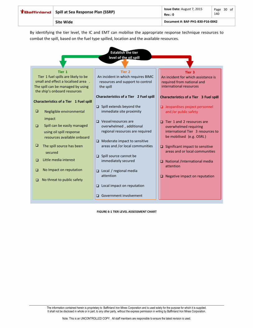
By identifying the tier level, the IC and EMT can mobilise the appropriate response technique resources to
combat the spill, based on the fuel type spilled, location and the available resources.
FIGURE 6-1 TIER LEVEL ASSESSMENT CHART
Tier 2 An incident in which requires BIMC
resources and support to control the spill
Characteristics of a Tier 2 Fuel spill :
Spill extends beyond the immediate site proximity
Vessel resources are overwhelmed , additional regional resources are required
Moderate impact to sensitive areas and / or local communities
Spill source cannot be immediately secured
Local / regional media attention
Local impact on reputation
Government involvement
Tier 3 An incident for which assistance is required from national and international resources
Characteristics of a Tier 3 Fuel spill :
Jeopardises project personnel and / or public safety
Tier 1 and 2 resources are overwhelmed requiring international Tier 3 resources to be mobilised ( e . g . OSRL )
Significant impact to sensitive areas and or local communities
National / International media attention
Negative impact on reputation
Tier 1
Tier 1 fuel spills are likely to be
small and effect a localised area . The spill can be managed by using the ship’s onboard resources
Characteristics of a Tier 1 Fuel spill :
Negligible environmental
impact
Spill can be easily managed
using oil spill response resources available onboard
The spill source has been
secured
Little media interest
No Impact on reputation
No threat to public safety
Establish the tier level of the oil spill

Spill at Sea Response Plan (SSRP) Issue Date: August 7, 2015
Rev.: 0
Page 31 of 140
Site Wide Document #: BAF-PH1-830-P16-0042
The information contained herein is proprietary to Baffinland Iron Mines Corporation and is used solely for the purpose for which it is supplied. It shall not be disclosed in whole or in part, to any other party, without the express permission in writing by Baffinland Iron Mines Corporation.
Note: This is an UNCONTROLLED COPY. All staff members are responsible to ensure the latest revision is used.
7 CONSTRAINT – EXTREME WEATHER CONDITIONS The open water season along the Northern Shipping Route is generally from mid-July to mid-October. For
this phase of the Mary Project Development, BIMC expects that all shipping activities will occur during the
open water period. Shipping of fuel in pack ice or under landfast ice conditions is not planned. Only
shipment of iron ore (ore carrier) may encounter ice conditions during the shoulder season.
BIMC acknowledges that ice flows may be encountered at the beginning and at the end of the shipping
season. Therefore, response to ore carriers emergencies that result or may result in fuel spill may be
complicated by the presence of ice during the shoulder season of the shipping period.
7.1 TIER 2 RESPONSE DURING ICE MELT (JULY)
The tug boats used by BIMC are ice class vessel and can manoeuvre through broken ice. However, at the
beginning of the open water shipping season, the presence of drifting broken ice may pose challenges for
the effective deployment of containment booms.
For a Tier 2 response, during this period, BIMC may dispatch up to three vessels to assist in containment
of the fuel slick. The functions of the vessels are as follows:
One tug (ice class vessel) to push away broken ice from the scene of the accident;
Two line boat to deploy containment booms.
Spill recovery would begin as soon as the spill is contained and the weather conditions (winds) permit.
After deployment of the containment booms, one of the line boat would tow the floating barge equipped
with a skimmer to pick up the slick.
7.2 TIER 2 RESPONSE DURING FREEZE-UP (OCTOBER)
Freeze up occurs rapidly. As ice forms, it is no longer feasible to deploy boom or containment equipment.
Furthermore, no “on-ice” intervention can take place until the ice cover is sufficiently thick to support
mobile equipment.
BIMC’s shipping activities during this period will be limited to ore shipment (ore carriers using IFO for
propulsion). Should a release of fuel occur during this period (mechanism for spill to occur undefined),
there is a remote possibility that the IFO would remain trapped under/within ice until spring break-up.
The Tier 2 response activity would consist of monitoring potential movement of fuel under ice as soon as
thickness of the ice permits the deployment of mobile equipment.
7.3 TIER 2 RESPONSE DURING ICE COVERED PERIOD (END OF OCTOBER TO MID-JULY)
Once the Project Certificate No 005 is amended by the NIRB to allow winter shipping of ore via the
Northern Route, the SSRP will be amended to address response for winter shipping operations.

Spill at Sea Response Plan (SSRP) Issue Date: August 7, 2015
Rev.: 0
Page 32 of 140
Site Wide Document #: BAF-PH1-830-P16-0042
The information contained herein is proprietary to Baffinland Iron Mines Corporation and is used solely for the purpose for which it is supplied. It shall not be disclosed in whole or in part, to any other party, without the express permission in writing by Baffinland Iron Mines Corporation.
Note: This is an UNCONTROLLED COPY. All staff members are responsible to ensure the latest revision is used.
As part of the winter shipping operation, BIMC will have two Ice Management Vessels (ice breakers)
stationed at Milne Port. These IMVs will be available to assist distress ore carriers in emergency situation.
Only ice class ore carriers will navigate the Northern Shipping Route during the ice covered period of mid-
October to mid-July (Zone-date system established under the CSA 2001). Ore carriers use IFO for
propulsion fuel. Because of the design of the ice class ore carriers and the physical position of the fuel
tanks within the carrier hull, a puncture of the ore carrier’s fuel tanks is unlikely, even if the vessel is
involved in a collision.
Catastrophic Event
An uncontrollable IFO fuel release to the sea would most likely result from an explosion, extensive
corrosion due to poor maintenance of the vessel (structural integrity of the ship), or, sabotage/human
error within the ship, and, would require extensive physical damage to the fuel tank(s) as well as puncture
of the ship’s hull, in which case, the ship is more likely to sink.
For such a scenario, BIMC’s response effort will focus on rescuing the ship crew with the use of helicopter
and/or BIMC’s IMVs.
Event Leading to Spill of IFO Fuel on Ice or Under Ice
Although the sequence of events leading to such a scenario is not understood, there is a remote possibility
that the content of the ore carrier’s fuel tank (up to 2000 m3 of IFO) could be release to sea as a result of
an “undefined” on-board ship accident.
After receiving notification of the incident from the CCG, BIMC’s Tier 2 response for such a scenario would
consist of:
1) Dispatch the IMVs to the scene of the incident (arrival time between 4 to 12 hours depending on
location of the distressed vessel);
2) Deploy on-ice fuel containment equipment – if practical to do so (Refer: SOPs related to working
on ice, Appendix 3);
3) If ice is sufficiently thick to support mobile equipment (Refer: SOP for testing of ice strength,
Appendix 3), mobile equipment (loader) is used to build containment berms around the spilt fuel
on ice surface.
4) Recovery of the contaminated snow commences as soon as the source of the leak is contained.
Loaders are used to scoop contaminated snow into containers. The containers are transported
to Milne Port by the IMVs and the contaminated snow is dumped in the landfarm.
5) Bore holes are drilled through the ice at a number of locations around the damaged ship to detect
the presence of fuel under ice. If fuel under ice is detected, various SOPs are presented in
Appendix 2 for under ice fuel recovery.
6) Once the damaged ore carrier is towed away from the accident site, under ice monitoring for the
presence of fuel around the incident site continues until the melt. This monitoring will track the
movement of under ice fuel slick should it occur.

Spill at Sea Response Plan (SSRP) Issue Date: August 7, 2015
Rev.: 0
Page 33 of 140
Site Wide Document #: BAF-PH1-830-P16-0042
The information contained herein is proprietary to Baffinland Iron Mines Corporation and is used solely for the purpose for which it is supplied. It shall not be disclosed in whole or in part, to any other party, without the express permission in writing by Baffinland Iron Mines Corporation.
Note: This is an UNCONTROLLED COPY. All staff members are responsible to ensure the latest revision is used.
8 RESPONSE TECHNIQUE SELECTION The Response Techniques available to BIMC are;
Assess the Spill (Appendix 3.1)
Assisted Natural Dispersion (Appendix 3.2)
Shoreline Protection and Cleanup (Appendix 3.3)
At Sea Containment and Recovery (Appendix 3.4)
Spill Response in Ice (Appendix 3.5)
Spill Response in Broken Ice (Appendix 3.6)
Spill Response Under Ice (Appendix 3.7)
Shoreline Cleanup Assessment Technique (SCAT) (Appendix 3.8)
Waste Management (Appendix 3.9)

Spill at Sea Response Plan (SSRP) Issue Date: August 7, 2015
Rev.: 0
Page 34 of 140
Site Wide Document #: BAF-PH1-830-P16-0042
The information contained herein is proprietary to Baffinland Iron Mines Corporation and is used solely for the purpose for which it is supplied. It shall not be disclosed in whole or in part, to any other party, without the express permission in writing by Baffinland Iron Mines Corporation.
Note: This is an UNCONTROLLED COPY. All staff members are responsible to ensure the latest revision is used.
8.1 RESPONSE TECHNIQUE DECISION FLOWCHART
OIL SPILL
Vessel Crew SOPEP Cleanup
NO
NO
Assess the SpillAppendix 3.1
IFOArctic Diesel or Hydraulic Oil
At Sea Containment and Recovery,
Appendix 3.4
Waste Management Section 9
Assisted Natural Dispersion
Appendix 3.2
Shoreline Protection and Cleanup
Appendix 3.3
NO
YES
YES
RESPONSE REQUIRED AND
SAFE?
Continue to Assess the Spill Appendix 3.1
IS ICE PRESENT OR ANTICIPATED?
OIL TYPE?
Spill Response Under IceAppendix 3.7
Spill Response in Ice
Appendix 3.5
Spill Response in Broken IceAppendix 3.6
YES
SLICK HEADING TOWARDS SHORELINE
YESSCAT
Appendix 3.8
Waste Management Section 9
Continue to Assess the Spill Appendix 3.1
Demobilisation
SPILL CONTAINED ON DECK?
Initial Assessment of the SpillMade by the Vessel Crew
Vessel Crew SOPEP Cleanup
BIMC monitor situation until completion
FIGURE 8-1 RESPONSE TECHNIQUE DECISION FLOW CHART
Figure 8-1 shows BIMC’s appropriate response technique selection decision options. This flow chart can
be used to implement the appropriate strategies in an effective manner.
The Tier 1, 2 and 3 response resources that support these response techniques are contained in Section
10, Spill Response Resources (p.36)
Appendix 3 provides Standard Operating Procedures (SOPs) associated with each of these response
techniques.

Spill at Sea Response Plan (SSRP) Issue Date: August 7, 2015
Rev.: 0
Page 35 of 140
Site Wide Document #: BAF-PH1-830-P16-0042
The information contained herein is proprietary to Baffinland Iron Mines Corporation and is used solely for the purpose for which it is supplied. It shall not be disclosed in whole or in part, to any other party, without the express permission in writing by Baffinland Iron Mines Corporation.
Note: This is an UNCONTROLLED COPY. All staff members are responsible to ensure the latest revision is used.
9 WASTE MANAGEMENT All waste collected from clean-up operation is sent off-site for treatment at an approved treatment
facility.
For storage of recovered fuel slick (from skimmers):
A 25 m3 inflatable barges is available and stored at Milne Port.
Up two 150 m3 storage (bladders) at Milne Port (bladders can be loaded on barge as required).
Slop recovered from skimming the spill is stored in this inflatable barge (temporarily) until a large
vessel can be chartered to store and transport the recovered slop to an approved treatment
facility (most likely Valleyfied, PQ).
For slick recovered from shore clean up that may contain sand/gravel and shore debris – barge
used to transport to transfer facility/point (i.e. larger vessel chartered to transport contaminated
wastewater). Soil/debris stored separated and transported to an approved treatment facility
(most likely Valleyfied, PQ).
Same applies for dead birds and wildlife.
No storage, treatment or disposal of recovered waste at Milne Port, except for contaminated
snow recovered from spill on ice during winter.
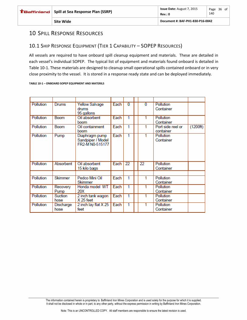
Spill at Sea Response Plan (SSRP) Issue Date: August 7, 2015
Rev.: 0
Page 36 of 140
Site Wide Document #: BAF-PH1-830-P16-0042
The information contained herein is proprietary to Baffinland Iron Mines Corporation and is used solely for the purpose for which it is supplied. It shall not be disclosed in whole or in part, to any other party, without the express permission in writing by Baffinland Iron Mines Corporation.
Note: This is an UNCONTROLLED COPY. All staff members are responsible to ensure the latest revision is used.
10 SPILL RESPONSE RESOURCES
10.1 SHIP RESPONSE EQUIPMENT (TIER 1 CAPABILITY – SOPEP RESOURCES)
All vessels are required to have onboard spill cleanup equipment and materials. These are detailed in
each vessel’s individual SOPEP. The typical list of equipment and materials found onboard is detailed in
Table 10-1. These materials are designed to cleanup small operational spills contained onboard or in very
close proximity to the vessel. It is stored in a response ready state and can be deployed immediately.
TABLE 10-1 – ONBOARD SOPEP EQUIPMENT AND MATERILS

Spill at Sea Response Plan (SSRP) Issue Date: August 7, 2015
Rev.: 0
Page 37 of 140
Site Wide Document #: BAF-PH1-830-P16-0042
The information contained herein is proprietary to Baffinland Iron Mines Corporation and is used solely for the purpose for which it is supplied. It shall not be disclosed in whole or in part, to any other party, without the express permission in writing by Baffinland Iron Mines Corporation.
Note: This is an UNCONTROLLED COPY. All staff members are responsible to ensure the latest revision is used.
10.2 BAFFINLAND SPILL EQUIPMENT (TIER 2 CAPABILITY)
10.2.1 MILNE PORT RESOURCES
Table 10-2 details BIMC’s spill response capability. These resources are stored in a response ready state
and can be mobilised in 1 hour.
The IC is responsible for mobilising these resources.
TABLE 10-2 TIER 2 CAPABILITY
Tier 2 resources based at Milne Port/Mary River
Resource Quantity Details/Image
Helicopter 2
Single engine
On site between June 15th to
September 15th.
Dornier
Aeroplane 1 Fixed wing aircraft
Containment
Boom kits 1
1500 m in towable lengths long
x 24” wide
Anchor kits x 9
Towing bridles x 10
Spill Response
Unit 8
Includes;
300 bales of sorbent Pads
8-8’ Socks
8-4’ Socks
Plug N Dike 10 lb container

Spill at Sea Response Plan (SSRP) Issue Date: August 7, 2015
Rev.: 0
Page 38 of 140
Site Wide Document #: BAF-PH1-830-P16-0042
The information contained herein is proprietary to Baffinland Iron Mines Corporation and is used solely for the purpose for which it is supplied. It shall not be disclosed in whole or in part, to any other party, without the express permission in writing by Baffinland Iron Mines Corporation.
Note: This is an UNCONTROLLED COPY. All staff members are responsible to ensure the latest revision is used.
12 large pillows
small pillows
2 plug patties (instant leak stop)
2 neoprene drain
covers
telescopic shovel
25 lb Bag granular/peat
2 pr. Nitrile gloves
2 Tyvek poly-coated suits
1 roll (20) disposal bags
1 roll of barrier tape
Castors available
Capacity 546 litres / 120 gallons.
Overpack spill kit 4
Includes;
100 Sorbent pads
6 small pillows
2 large pillows
5 – 8’ socks
5 – 10’ socks
2 – 4’ socks
Sorbent granular bag - 25lb
Plug patties
Goggles
Gloves
Tyvek suits

Spill at Sea Response Plan (SSRP) Issue Date: August 7, 2015
Rev.: 0
Page 39 of 140
Site Wide Document #: BAF-PH1-830-P16-0042
The information contained herein is proprietary to Baffinland Iron Mines Corporation and is used solely for the purpose for which it is supplied. It shall not be disclosed in whole or in part, to any other party, without the express permission in writing by Baffinland Iron Mines Corporation.
Note: This is an UNCONTROLLED COPY. All staff members are responsible to ensure the latest revision is used.
Multizorb
Granular 500 12 kg bags
Transfer Pump 1 Custom pump skid for emergency fuel transfer from one tank to
another
Transfer Pump
Hose 8 2” x 8 m
Arctic mini berm -
small 12 0.5m x 0.5m x 0.15m
Arctic mini berm 12 1m x 1m x 0.15m
Insta Berm 2 3m x 3m x 0.4m
Sorbent sheets 300
Workboat 1
Aluminium Hull
Outboard
Towing post
Drum Skimmer
and diesel power
pack
1 7.5 tonnes per hour
Brush/Drum
skimmer
complete with
diesel driven
powerpack
1
20 tonnes per hour, brush
attachment for higher viscosity
product recovery
Vacuum Truck 1 13,500 L capacity
Steel Drums 20 200 Litre Capacity
Rakes 12 For beach cleaning
Perforated
Shovels 12

Spill at Sea Response Plan (SSRP) Issue Date: August 7, 2015
Rev.: 0
Page 40 of 140
Site Wide Document #: BAF-PH1-830-P16-0042
The information contained herein is proprietary to Baffinland Iron Mines Corporation and is used solely for the purpose for which it is supplied. It shall not be disclosed in whole or in part, to any other party, without the express permission in writing by Baffinland Iron Mines Corporation.
Note: This is an UNCONTROLLED COPY. All staff members are responsible to ensure the latest revision is used.
Pitch Fork 12
Personal
Flotation Devices 12
Sand Stock pile 10 ton for berming or making sand bags
Wildlife
Protection Kit 1
Includes;
Pyrotechnics (shell crackers, screamers, propane cannons for shore
based spills.
Visual scare tactics (helicopters, emergency response vessels)
Broadcast Sounds (Breco bird scarer)
Netting
Spill Response
Vessels (2
charter tug
boats and two
line boats at
Milne Port)
Ability to cover
a range of
100nm
Enclosed wheel
house
Onboard
accommodation
Onboard crane
Large deck
space for
working areas
and equipment
storage
Ability to
maintain a low
speed of 1 to 2
kts

Spill at Sea Response Plan (SSRP) Issue Date: August 7, 2015
Rev.: 0
Page 41 of 140
Site Wide Document #: BAF-PH1-830-P16-0042
The information contained herein is proprietary to Baffinland Iron Mines Corporation and is used solely for the purpose for which it is supplied. It shall not be disclosed in whole or in part, to any other party, without the express permission in writing by Baffinland Iron Mines Corporation.
Note: This is an UNCONTROLLED COPY. All staff members are responsible to ensure the latest revision is used.
Inflatable
barge
2 X 10 m³ Capacity
Towable Stored at Milne Port
Waste
Storage
Bladders
6 at 25 m3 capacity Stored on site at Milne Port
10.2.2 BIMC RESPONSE TIMES
Accident Location Distance from Milne Port
Travel time by BIMC tugs from Milne Port to reach Accident site
Full containment fuel spill (booming)
Entrance to Baffin Bay 120 nm 12 hours Up to 2 days
Mid Eclipse Sound 80 nm 8 hours Up to 2 days
Entrance to Milne Inlet 40 nm 4 hours Up to 2 days

Spill at Sea Response Plan (SSRP) Issue Date: August 7, 2015
Rev.: 0
Page 42 of 140
Site Wide Document #: BAF-PH1-830-P16-0042
The information contained herein is proprietary to Baffinland Iron Mines Corporation and is used solely for the purpose for which it is supplied. It shall not be disclosed in whole or in part, to any other party, without the express permission in writing by Baffinland Iron Mines Corporation.
Note: This is an UNCONTROLLED COPY. All staff members are responsible to ensure the latest revision is used.
10.3 TIER 3 ARRANGEMENTS
10.3.1 OSRL
BIMC is an Associate member with OSRL, therefore has immediate access to Tier 3 technical advice, resources
and expertise 365 days a year on a 24 hr basis.
Table 10-3 summarises the OSRL service level agreement (SLA) available to BIM.
TABLE 10-3 OSRL SERVICE LEVEL AGREEMENT SUMMARY
Service Service Standard
Response notification service/advice
In an incident a call should be placed to one of the following numbers:
Emergency Contact:
TELEPHONE UK/Bahrain +44 (0) 2380 331 551 Singapore +65 6266 1566
Emergency Contact:
FAX UK/Bahrain +44 (0) 2380 724 314 Singapore +65 6266 2312
The Duty Manager will speak and advise BIMC immediately, or call BIMC back within 10 minutes.
Spill response equipment
Response equipment is housed in secure facilities in Southampton, Fort Lauderdale, Bahrain and Singapore. Response equipment is customs cleared and response ready. Refer: OSRL Yearbook for a complete list of equipment available, www.oilspillresponse.com and Refer: the equipment stockpile status report http://www.oilspillresponse.com/activate-us/equipment-stockpile-status-report
As per the SLA, BIMC can mobilise up to 50 % of the global stockpile. If there is more than one spill, BIMC can mobilise 50 % of what remains.
World-wide transportation of equipment
Hercules L382G in the UK will be used for transportation of Tier 3 response equipment. The aircraft are available for loading at the nominated base within 4 hrs from notification.
24 hour access to global network of cargo and passenger charter services through a dedicated broker.
Spill trajectory and tracking
Trajectory and stochastic services for surface or subsurface spills on request, and backtrack services for surface spills using commercial modelling software:
Oil Spill Information System (OSIS) OILMAP Oil Spill Contingency and Response Model (OSCAR)
Satellite imagery services can be provided on request.
Response Personnel
OSRL can respond to 2 major oil spills simultaneously, each with a maximum of 18 OSRL responders:
1 x Incident Manager 1 x Response Manager 1 x Administrator 14 x Spill Response Specialists 1 x Technical Specialist
A Technical Advisor can be dispatched to offer support to BIMC if they have a spill incident or the potential for an incident to occur. This is provided free of charge for the initial assessment period of up to 48 hrs. If a full response team is then mobilised, the technical advisor will form part of the available team headcount.

Spill at Sea Response Plan (SSRP) Issue Date: August 7, 2015
Rev.: 0
Page 43 of 140
Site Wide Document #: BAF-PH1-830-P16-0042
The information contained herein is proprietary to Baffinland Iron Mines Corporation and is used solely for the purpose for which it is supplied. It shall not be disclosed in whole or in part, to any other party, without the express permission in writing by Baffinland Iron Mines Corporation.
Note: This is an UNCONTROLLED COPY. All staff members are responsible to ensure the latest revision is used.
OSRL Response Times
The following table provides an estimation of response times for mobilisation of Tier 3 resources to Baffin
Island. OSRL can provide more accurate timescales at the time of a real incident.
Note: All response times are subject to suitable availability of aircraft, weather conditions, security and over flight clearances. Additional time may be required to ensure timely application of applicable visas for Spill Response Specialists.
Resource Tier 3 containment and recovery equipment
Provider OSRL charter on BIMC’s behalf
Start Location Southampton
Destination Mary River Pond Inlet
Aircraft type(s) Variable based on availability
Mobilisation and loading time
6 hours
Time for over flight passes 24 – 48 hours
Transit
Start to destination (total)
27 Hours
Fuel stop in (Airport code)
KEF and YFB
Total 57 – 81 hours
Comment Payload and mobilisation time is dependent upon aircraft
availability.

Spill at Sea Response Plan (SSRP) Issue Date: August 7, 2015
Rev.: 0
Page 44 of 140
Site Wide Document #: BAF-PH1-830-P16-0042
The information contained herein is proprietary to Baffinland Iron Mines Corporation and is used solely for the purpose for which it is supplied. It shall not be disclosed in whole or in part, to any other party, without the express permission in writing by Baffinland Iron Mines Corporation.
Note: This is an UNCONTROLLED COPY. All staff members are responsible to ensure the latest revision is used.
Logistical Support
OSRL respond to locations around the world. BIMC has an established logistics network in Northern Canada.
To ensure equipment gets through customs clearance quickly and on to the lay down area for response, BIMC
shall make the necessary arrangements for the equipment and OSRL personnel once in country.
An overview of the responsibilities for Client and OSRL are presented in Figure 10-1.
Callout
Mobilise
equipment /
Technical
Advisor
Get trucks/
aircraft/
vessels
Load trucks/
air craft /
vessel
Transport to
airport/port
Load
aircraft/
vessel/truck
Flight/transit
Customs
and
Immigration
Unload
Transport
to site
Onsite
operations
Demobilise
Closeout
Waste
Management
Plan
Personnel
Boats
Aircraft
Vehicles
BIMC
Oil Spill
Response
Responsibilities
FIGURE 10-1 LOGISTICS RESPONSIBILITY

Spill at Sea Response Plan (SSRP) Issue Date: August 7, 2015
Rev.: 0
Page 45 of 140
Site Wide Document #: BAF-PH1-830-P16-0042
The information contained herein is proprietary to Baffinland Iron Mines Corporation and is used solely for the purpose for which it is supplied. It shall not be disclosed in whole or in part, to any other party, without the express permission in writing by Baffinland Iron Mines Corporation.
Note: This is an UNCONTROLLED COPY. All staff members are responsible to ensure the latest revision is used.
10.3.2 ADDITIONAL TIER 3 RESOURCES
Contaminated Wildlife Response Resources
Sea Alarm
Through OSRL, BIMC has access to an external international wildlife response capability. The Sea Alarm
Foundation (SAF) has extensive experience in dealing with contaminated wildlife emergencies. Specialised
wildlife response equipment is pre-packaged, custom approved and stockpiled at OSRL in Southampton. This
equipment can be mobilised on request by BIM. The mobilisation of Tier 3 wildlife emergency teams is not
guaranteed and will depend on availability and voluntary commitment. This equipment is available 365 days a
year on a 24 hr basis, as part of the Service Level Agreement. Experts from outside of OSRL and SAF are required
to operate the equipment.
According to the SeaAlarm Country Wildlife Response Profile for Canada3, the Environmental Protection Branch
(EPB) of Environment Canada (EC) is responsible for preparation and response to contaminated wildlife
incidents.
Table 10-4 provides contact details of other Wildlife response organisations that may be able to respond in
the event of wildlife becoming contaminated.
TABLE 10-4: WILDLIFE EMERGENCY CONTACTS
3 Available [online] at: http://www.sea-alarm.org/publications/country-wildlife-response-profiles/

Spill at Sea Response Plan (SSRP) Issue Date: August 7, 2015
Rev.: 0
Page 46 of 140
Site Wide Document #: BAF-PH1-830-P16-0042
The information contained herein is proprietary to Baffinland Iron Mines Corporation and is used solely for the purpose for which it is supplied. It shall not be disclosed in whole or in part, to any other party, without the express permission in writing by Baffinland Iron Mines Corporation.
Note: This is an UNCONTROLLED COPY. All staff members are responsible to ensure the latest revision is used.
The Global Response Network (GRN)
OSRL can also facilitate the mobilisation of further resources through the Global Response Network (GRN). The
GRN is a collaboration of six major oil industry funded spill response organisations whose mission is to harness
cooperation and maximise the effectiveness of spill response services worldwide. It includes:
Alaska Clean Seas (ACS)
Australia Marine Oil Spill Centre (AMOSC)
ECRC (Eastern Canada Response Corporation)
Marine Spill Response Corporation (MSRC)
Oil Spill Response Limited (OSRL) (America, Europe, Middle East, Africa, Asia and Pacific)
Western Canada Marine Response Corporation (WCMRC)
10.4 ADDITIONAL ASSISTANCE AGREEMENT
BIMC recognizes that organizing an effective response for a large spill event may require the use of
additional tugs to effectuate sweeps and resupply crews at the incident scene, skimmers and barges for
storage of waste.
Depending on where the incident occurs, it may be more practical to deliver OSRL’s support equipment
to a port where additional boat can be hired to transport the response equipment to the spill site.
As part of the on-going development and continuous improvement of BIMC’s response capabilities, BIMC
is pursuing Assistance Agreements with selected tug boat operators operating in the St Lawrence River or
the Eastern seaboard as well as shipping providers for the provision of emergency transportation of
response equipment in the event of a spill.

Spill at Sea Response Plan (SSRP) Issue Date: August 7, 2015
Rev.: 0
Page 47 of 140
Site Wide Document #: BAF-PH1-830-P16-0042
The information contained herein is proprietary to Baffinland Iron Mines Corporation and is used solely for the purpose for which it is supplied. It shall not be disclosed in whole or in part, to any other party, without the express permission in writing by Baffinland Iron Mines Corporation.
Note: This is an UNCONTROLLED COPY. All staff members are responsible to ensure the latest revision is used.
REFERENCE INFORMATION
Introduction
This section contains background information and data on operating at Baffin Island, Canada. The section
covers:
Fuel Inventory
Fuel Characteristics in Cold Marine Environment
Mitigation Measures
Historic Spill Data
Spill Response Governance
Fuel spill risk assessment
11 FUEL CHARACTERISTICS
Table 11-1 details the fuel volumes and characteristics that may be onboard transiting vessels under the
scope of this SSRP. This table should be used for information only and not for possible spill scenarios.
Reference should be made to Section 15, Fuel Spill Risk Assessment (p.59) for credible spill scenarios.
TABLE 11-1 FUEL INVENTORY
Location Fuel Type Volume °API SG Viscosity (cSt @ 40°C)
Pour Point (°C)
Wax Content
ITOPF Group
Tanker
IFO
Combined =
17,000m³
17.6 0.949 0.99 -1 0 III
Low Sulphur Fuel
17.6 0.949 0.99 -1 0 III
Arctic Diesel
30-37 0.84-088 -17°C - -30°C
II
Jet A fuel 45 0.8 1-1.9 I
Marine Diesel
30-37 0.84-088 -17°C - -30°C
II
Hydraulic Fluid
<35 0.88 100 <0 0 III
Ore Carrier
IFO
Combined = 3,000m³
17.6 0.949 0.99 -1 0 III
Low Sulphur Fuel
17.6 0.949 0.99 -1 0 III
Tug Boats Marine Diesel
100m³ 30-37 0.84-088 -17°C - -30°C
II
Dry Cargo Vessels
IFO
1500 m³
17.6 0.949 0.99 -1 0 III
Low Sulphur Fuel
17.6 0.949 0.99 -1 0 III
Hydraulic Fluid
<35 0.88 100 <0 0 III

Spill at Sea Response Plan (SSRP) Issue Date: August 7, 2015
Rev.: 0
Page 48 of 140
Site Wide Document #: BAF-PH1-830-P16-0042
The information contained herein is proprietary to Baffinland Iron Mines Corporation and is used solely for the purpose for which it is supplied. It shall not be disclosed in whole or in part, to any other party, without the express permission in writing by Baffinland Iron Mines Corporation.
Note: This is an UNCONTROLLED COPY. All staff members are responsible to ensure the latest revision is used.
Detailed below is a summary of the properties of each fuel and its likely behaviour when spilt.
IFO and Low Sulphur Fuel - ITOPF Group 3
IFO and Low Sulphur Fuel, are classified in Group 3 of the ITOPF classification according to their specific
gravity. Group 3 oils undergo evaporation at a moderate rate; about one third will evaporate within 24
hours. This Group 3 characteristics are also highly variable, particularly in their tendency to emulsify and
in their pour points.
The pour point affects the viscosity of the fuel and hence its dispersibility. The pour point is the
temperature at which a fuel becomes semi-solid and ceases to flow. This happens because the waxes in
the fuel crystallize out of solution. This causes the fuel to “gel” and greatly increase in viscosity.
The pour point of spilled fuel does not remain constant over time. It will gradually increase because
evaporation of the lighter components of the fuel causes the waxes in the residual fuel to become
concentrated, thus forcing their precipitation. This means that a freshly spilled fuel with a relatively low
pour point may not gel, but may gel after some weathering.
This type of fuel normally forms emulsions readily; the rate of this formation and the stability of the
emulsions formed are highly variable depending on their asphaltene content. High asphaltene content
will promote rapid emulsification which can result in substantial increase in the viscosity and reduce the
amenability to dispersants.
Fuels with high asphaltene content are typically heavier and more persistent fuels. Because of this nature,
Group 3 is often classified as persistent; they may not be completely removed from an affected
environment as a result of weathering processes or clean-up operations. This may result in long term
effects to the environment.
Arctic Diesel
Arctic diesel fuel is a light petroleum distillate. Diesels vary in their properties, but have a specific gravity
in the range 0.84-0.88 g/cm3 (30-37oAPI), with pour points of between -17oC and -30oC. As such they are
generally classed in Group II, i.e. light persistent fuel, under the ITOPF classification according to their
specific gravity4.
Although classed as persistent, diesels contains a high proportion of light-ends which means that
evaporation will be an important process contributing to the removal of spilt diesel from the sea surface.
Evaporation of the lighter ends will be enhanced by higher wind speeds and warmer sea and air
temperatures. Small diesel spills will usually evaporate and disperse within a day or less.
When spilled on water, arctic diesel spreads very quickly to a thin film of rainbow and silver sheens which
elongates rapidly in the direction of the prevailing wind and waves. The low density and viscosity of the
diesel contributes to rapid dispersal of the fuel into the water column; the speed of dispersion increases
4 ITOPF. 2010. Handbook 2010/11. Fate of Marine Oil Spills.

Spill at Sea Response Plan (SSRP) Issue Date: August 7, 2015
Rev.: 0
Page 49 of 140
Site Wide Document #: BAF-PH1-830-P16-0042
The information contained herein is proprietary to Baffinland Iron Mines Corporation and is used solely for the purpose for which it is supplied. It shall not be disclosed in whole or in part, to any other party, without the express permission in writing by Baffinland Iron Mines Corporation.
Note: This is an UNCONTROLLED COPY. All staff members are responsible to ensure the latest revision is used.
with the wind speed. Dispersed diesel is readily and completely degraded by naturally occurring microbes,
under time frames of one to two months.
Dispersed diesel in the water column can adhere to fine-grained suspended sediments (adsorption) which then
settle out and may be deposited on the seafloor. This process is more likely to occur near river mouths where
fine-grained sediments are carried in by rivers. It is less likely to occur in the open marine environment5.
Under certain sea states diesel may form an emulsion although this will be unstable due to the absence of
asphaltenes.
Hydraulic Fluid
Hydraulic fluid (specific gravity 0.88 g/cm3, °API < 35, viscosity 100 cSt @ 30oC, pour point < 0oC, flash point
>60oC) is a relatively viscous fluid and is classed in Group 3 under the ITOPF classification according to their
specific density6.
Hydraulic fluid has a low volatility and moderate flash point, so there is no major safety issue when dealing
with this fluid. However, this fluid is fairly persistent in the environment. Expect limited spread and minimal
loss through evaporation and natural dispersion. The action of mixing energy on hydraulic fluid is likely to
produce a frothy emulsion.
Lubricating Fluid
Lubricating fluid or ‘lube oil” (specific gravity 0.87 g/cm3, °API 29, viscosity = 79-86 cSt @ 20oC, pour point -
35oC, flash point >60oC) is relatively viscous fluid and is classed in Group 3 under the ITOPF classification
according to their specific density7.
Lubricating fluid flows easily and is easily dispersed if treated promptly8. However, this fluid is not easily
assimilated by the environment and tends to persist in the environment. There is likelihood that the action of
mixing energy on lubricating fluid will produce frothy emulsions. Emulsion can greatly increase the fluid
viscosity as well as the total volume of fluid while inhibiting all other natural weathering processes (which act
to reduce the spill volume) and the effectiveness of most response options. In addition, with the low volatility
and moderate flash point, there is no major safety issue when dealing with this fluid.
5 NOAA. 2006. Fact Sheet: Small Diesel Spills (500-5000 gallons), NOAA Office of Response and Restoration.
6 ITOPF. 2010. Handbook 2010/11. Fate of Marine Oil Spills.
7 ITOPF. 2010. Handbook 2010/11. Fate of Marine Oil Spills.
8 EPA, 2009, Types of Refined Petroleum Products http://www.epa.gov/emergencies/content/learning/refined.htm [Accessed February, 2010]

Spill at Sea Response Plan (SSRP) Issue Date: August 7, 2015
Rev.: 0
Page 50 of 140
Site Wide Document #: BAF-PH1-830-P16-0042
The information contained herein is proprietary to Baffinland Iron Mines Corporation and is used solely for the purpose for which it is supplied. It shall not be disclosed in whole or in part, to any other party, without the express permission in writing by Baffinland Iron Mines Corporation.
Note: This is an UNCONTROLLED COPY. All staff members are responsible to ensure the latest revision is used.
Jet A Fuel
Jet A Fuel (Specific Gravity 0.8 g/cm3, °API 45) is a kerosene type aviation gas-turbine engine fuel and is
categorised as Group 1 under the ITOPF classification9. Jet A1 flows easily and spreads rapidly. They are easily
dispersed and do not have any tendency to emulsify10.
As this fuel is composed of mainly the low-weight components, they are highly volatile. They will
evaporate and dissolve readily and leave little or no residue. However, many of these low-weight
components are toxic and potentially flammable and readily inhaled and are of concern for human health
and safety.
11.1 FUEL CHARACTERISTICS IN COLD MARINE ENVIRONMENTS
11.1.1 FUEL PROPERTIES
The main properties of fuel that affect its behaviour if split at sea are:
specific gravity (SG) (its density relative to pure water often expressed as an °API)
distillation characteristics (its volatility)
viscosity (its resistance to flow)
pour point (the temperature below which it will not flow)
The International Tanker Owners Pollution Federation (ITOPF) classifies oil into four main groups based roughly
on their SG. Predicted rates of dissipation are determined from the classification of the oil.
Figure 11-1 shows the oil classifications and the time anticipated for the oil to dissipate. The graph also
takes account of the competing process of emulsification, which for most oil leads to an increase in
volume. The curves on the graph represent an estimated ‘average’ behaviour for each group. The
behaviour of a particular oil may differ from the general pattern depending on its specific properties and
the environmental conditions at the time of the spill.
9 ITOPF. 2010. Handbook 2010/11. Fate of Marine Oil Spills.
10 NOAA. 1992. Introduction to Coastal Habitats and Biological Resources for Spill Response. Oil Behaviour and Toxicity.
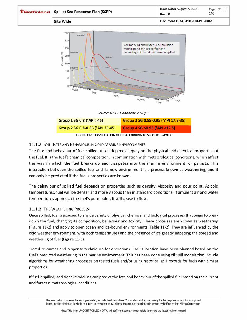
Spill at Sea Response Plan (SSRP) Issue Date: August 7, 2015
Rev.: 0
Page 51 of 140
Site Wide Document #: BAF-PH1-830-P16-0042
The information contained herein is proprietary to Baffinland Iron Mines Corporation and is used solely for the purpose for which it is supplied. It shall not be disclosed in whole or in part, to any other party, without the express permission in writing by Baffinland Iron Mines Corporation.
Note: This is an UNCONTROLLED COPY. All staff members are responsible to ensure the latest revision is used.
Source: ITOPF Handbook 2010/11
Group 1 SG 0.8 (°API >45) Group 3 SG 0.85-0.95 (°API 17.5-35)
Group 2 SG 0.8-0.85 (°API 35-45) Group 4 SG >0.95 (°API <17.5)
FIGURE 11-1 CLASSIFICATION OF OIL ACCORDING TO SPECIFIC GRAVITY
11.1.2 SPILL FATE AND BEHAVIOUR IN COLD MARINE ENVIRONMENTS
The fate and behaviour of fuel spilled at sea depends largely on the physical and chemical properties of
the fuel. It is the fuel’s chemical composition, in combination with meteorological conditions, which affect
the way in which the fuel breaks up and dissipates into the marine environment, or persists. This
interaction between the spilled fuel and its new environment is a process known as weathering, and it
can only be predicted if the fuel’s properties are known.
The behaviour of spilled fuel depends on properties such as density, viscosity and pour point. At cold
temperatures, fuel will be denser and more viscous than in standard conditions. If ambient air and water
temperatures approach the fuel’s pour point, it will cease to flow.
11.1.3 THE WEATHERING PROCESS
Once spilled, fuel is exposed to a wide variety of physical, chemical and biological processes that begin to break
down the fuel, changing its composition, behaviour and toxicity. These processes are known as weathering
(Figure 11-2) and apply to open ocean and ice-bound environments (Table 11-2). They are influenced by the
cold weather environment, with both temperatures and the presence of ice greatly impeding the spread and
weathering of fuel (Figure 11-3).
Tiered resources and response techniques for operations BIMC’s location have been planned based on the
fuel’s predicted weathering in the marine environment. This has been done using oil spill models that include
algorithms for weathering processes on tested fuels and/or using historical spill records for fuels with similar
properties.
If fuel is spilled, additional modelling can predict the fate and behaviour of the spilled fuel based on the current
and forecast meteorological conditions.

Spill at Sea Response Plan (SSRP) Issue Date: August 7, 2015
Rev.: 0
Page 52 of 140
Site Wide Document #: BAF-PH1-830-P16-0042
The information contained herein is proprietary to Baffinland Iron Mines Corporation and is used solely for the purpose for which it is supplied. It shall not be disclosed in whole or in part, to any other party, without the express permission in writing by Baffinland Iron Mines Corporation.
Note: This is an UNCONTROLLED COPY. All staff members are responsible to ensure the latest revision is used.
FIGURE 11-2: WEATHERING OF FUEL SPILLED IN THE MARINE ENVIRONMENT
TABLE 11-2: LOCATION-SPECIFIC WEATHERING OF FUEL.
Open Water In Ice (with increasing ice coverage)
Spreading
Cold water increases fuel viscosity and reduces the rate of spreading.
A fuel slick on cold water is usually thicker and occupies a smaller area than it would
in a warmer climate.
Rate of fuel spreading on ice is controlled primarily by fuel viscosity, so is slow in cold
temperatures. Deformed ice features may create pools of fuel,
whilst snow will absorb the fuel, reducing spreading.
Drift Fuel will drift according to wind and
currents.
Fuel will drift in the direction of drifting ice. Ice and low water temperature reduce the rate
of spreading and drifting of spilled fuel.
Evaporation
Surface fuel slicks will maintain a steady rate of evaporation.
Evaporation is reduced compared to more temperate climates.
Cold temperatures and increased fuel slick thickness (due to confinement in ice) reduces
both the rate and degree of evaporation.
Emulsification
Dependent on wave action mixing water droplets into the spilled fuel.
Mainly occurs in the presence of breaking waves.
Emulsification of fuel in ice is uncommon. Usually decreases or does not occur with
increasing ice coverage due to less energy.
Natural Dispersion
Natural dispersion is driven by wind or wave action so is dependent on sea state
rather than temperature.
Low rate of natural dispersion due to reduced energy conditions and opportunities for mixing
when fuel is spilled in the ice. Ice floes are a source of surface turbulence.
Biodegradation
Many marine bacteria are present even in cold water environments.
Bacteria consume the hydrocarbons in fuel, naturally reducing its volume.
Bacteria are present in ice covered areas, but may not be in contact with fuel as freely as in
open water. Bacteria slowly break down hydrocarbons.
Dissolution Fuel contains water-soluble compounds which may dissolve in the surrounding
water.
Very few of the water-soluble components of fuel could diffuse down to the bottom of the ice
sheet.
Due to the natural dynamism of the cold weather environment (instability of moving ice and changing weather
conditions) the weathering of spilled fuel may not necessarily follow the expected behaviour.

Spill at Sea Response Plan (SSRP) Issue Date: August 7, 2015
Rev.: 0
Page 53 of 140
Site Wide Document #: BAF-PH1-830-P16-0042
The information contained herein is proprietary to Baffinland Iron Mines Corporation and is used solely for the purpose for which it is supplied. It shall not be disclosed in whole or in part, to any other party, without the express permission in writing by Baffinland Iron Mines Corporation.
Note: This is an UNCONTROLLED COPY. All staff members are responsible to ensure the latest revision is used.
FIGURE 11-3: EFFECT OF COLD TEMPERATURES ON THE WEATHERING OF FUEL
In general, the cold environment will reduce the rate of weathering and decrease the spread of the fuel,
however the extent of the influence will be dependent on the location in which the fuel is present (Figure 11-4).
FIGURE 11-4: POTENTIAL FATES OF FUEL SPILLED IN COLD MARINE ENVIRONMENTS
Oil on the surface in open water
• Exposed to general weathering processes
Oil on water surface mixed in ice
• Exposed to general weathering processes
Oil submerged under broken ice
• Less likely to spread, not exposed to wind and wave action
• Reduced natural dispersion
Oil beneath ice
• Less likely to spread, not exposed to wind and wave action
• Reduced natural dispersion
Oil on ice
• Exposed to wind and ice action
• Spreads according to ice floe direction

Spill at Sea Response Plan (SSRP) Issue Date: August 7, 2015
Rev.: 0
Page 54 of 140
Site Wide Document #: BAF-PH1-830-P16-0042
The information contained herein is proprietary to Baffinland Iron Mines Corporation and is used solely for the purpose for which it is supplied. It shall not be disclosed in whole or in part, to any other party, without the express permission in writing by Baffinland Iron Mines Corporation.
Note: This is an UNCONTROLLED COPY. All staff members are responsible to ensure the latest revision is used.
12 MITIGATION MEASURES Risk management is a process that evaluates outputs from risk assessments and puts in place measures to
ensure that identified risks are acceptable or require mitigation. Risk reduction measures must be technically
feasible and cost effective (i.e. the associated costs should not be disproportionate to the benefits gained).
BIMC has put in place the following mitigation measures to reduce the potential for an fuel spill to occur and
the impact it may have.
Standard Operating Procedures (SOP’s)
SOPEP’s
Bridge resource management
COLREG’s
Ice Pilots
Crew training and certification
SMS
13 HISTORIC SPILL DATA The International Tanker Owners Pollution Federation Limited (ITOPF) manages a database with information
on nearly 10,000 spills associated with tankers, combined carriers and barges globally. Data collected includes
the number of spills annually and volumes spilt from these shipping sources every year since 1970. Tanker spill
sizes have been categorised as small spills (<7 tonnes), medium spills (between 7 and 700 tonnes) and large
spills (>700 tonnes).
The occurrence of large and medium tanker spills (defined as over 700 tonnes and 7 to 700 tonnes respectively)
has decreased over the last 4 decades. In the 2000s there was an annual average of 3.3 large spills and 14.9
medium spills; while in the 1970s an annual average of 24.6 large spills and 54.2 medium spills were recorded.
This spill decrease has been observed despite a steady increase in seaborne trading observed since the mid
1980’s (Fearn Research and Lloyds List Intelligence, cited in ITOPF 2012).
FIGURE 13-1: SEABORNE TRADE AND NUMBER OF TANKER SPILLS >7 TONNES, 1970 TO 2011. SOURCE: ITOPF, 2012
13.1 QUANTITIES OF SPILLS
Although the majority of spills that occur are small (< 7 tonnes), there is insufficient data available on the
number and amounts spilt due to inconsistent reporting. ITOPF has used data on medium to large spills to

Spill at Sea Response Plan (SSRP) Issue Date: August 7, 2015
Rev.: 0
Page 55 of 140
Site Wide Document #: BAF-PH1-830-P16-0042
The information contained herein is proprietary to Baffinland Iron Mines Corporation and is used solely for the purpose for which it is supplied. It shall not be disclosed in whole or in part, to any other party, without the express permission in writing by Baffinland Iron Mines Corporation.
Note: This is an UNCONTROLLED COPY. All staff members are responsible to ensure the latest revision is used.
generate annual estimates of total spilt between 1970 and 2012. Based on this data, it is estimated that almost
5.75 million tonnes has been spilt through tanker incidents within that time with the vast majority occurring in
the 1970s.As with the number of spill incidents, the quantity spilt has reduced significantly over the past 4
decades (Figure 13-2).
FIGURE 13-2: SPILLS >7 TONNES PER DECADE SHOWING THE INFLUENCE OF A RELATIVELY SMALL NUMBER OF LARGE SPILLS ON THE
OVERALL FIGURE (ITOPF, 2012)
13.2 CAUSES OF SPILLS
The causes and circumstances of spills vary and have a significant effect on the final quantity spilt. Small and medium spills account for 95% of all incidents recorded with a large percentage, 40% for small and 29% for medium, of these occurring during loading and discharge at ports and terminals (Figure 13-3 and Figure 13-4 ). The remaining 5% of incidents are large spills, which have reduced over the years but incidents recorded show that allusions, collisions and groundings accounted for 59% of these large spills (Figure 13-5). Half of these incidents when the vessel was underway in open water (Figure 13-6).
FIGURE 13-3: INCIDENCE OF SPILLS <7 TONNES BY OPERATION AT TIME OF INCIDENT, 1974-2012

Spill at Sea Response Plan (SSRP) Issue Date: August 7, 2015
Rev.: 0
Page 56 of 140
Site Wide Document #: BAF-PH1-830-P16-0042
The information contained herein is proprietary to Baffinland Iron Mines Corporation and is used solely for the purpose for which it is supplied. It shall not be disclosed in whole or in part, to any other party, without the express permission in writing by Baffinland Iron Mines Corporation.
Note: This is an UNCONTROLLED COPY. All staff members are responsible to ensure the latest revision is used.
FIGURE 13-4: INCIDENCE OF SPILLS 7-700 TONNES BY OPERATION AT TIME OF INCIDENT,
1970-2012
FIGURE 13-5: INCIDENCE OF SPILLS >700 TONNES BY CAUSE, 1970-2012
FIGURE 13-6: INCIDENCE OF SPILLS >700 TONNES BY OPERATION AT TIME OF INCIDENT,
1970-2012

Spill at Sea Response Plan Issue Date: August 7, 2015
Rev.: 0
Page 57 of 140
Site Wide Document #: BAF-PH1-830-P16-0042
The information contained herein is proprietary to Baffinland Iron Mines Corporation and is used solely for the purpose for which it is supplied. It shall not be disclosed in whole or in part, to any other party, without the express permission in writing by Baffinland Iron Mines Corporation.
Note: This is an UNCONTROLLED COPY. All staff members are responsible to ensure the latest revision is used.
14 KEY CANADIAN ARCTIC STAKEHOLDERS The following authorities and organisations hold key roles in spill response incident management in the
Canadian Arctic.
14.1 THE CANADIAN COAST GUARD
The response to spills at the Milne Inlet site shall be managed in coordination with the Canadian Coast Guard
whom are the lead response agency north of 60°.
The Central & Arctic Regional Response Plan (2008) and the Baffin Region, Nunavut Area Plan outline the
Canadian Coast Guard’s response capability for the Baffin region. This plan is a component of the Canadian
Coast Guard National Response Plan which is the responsibility of the Director of Safety and Environmental
Response Systems, Ottawa. It establishes the framework and the procedures by which Central & Arctic Region
will prepare for, assess, respond to and document actions taken in response to pollution incidents in this
Region. This capability and the information contained in the Coast Guard plans are considered a valuable
resource in the planning and response to spills at the Milne Inlet Bulk Fuel Storage Facility.
14.2 ENVIRONMENT CANADA SCIENCE TABLE
The Environment Canada Science Table is a multi-agency, multidisciplinary group specializing in environmental
emergencies. The Science Table is designed to provide consolidated and coordinated environmental advice,
information and assistance in the event of an environmental emergency. The Science Table members represent
several federal, provincial, territorial and municipal government departments, aboriginal communities, private
sector agencies, and local individuals.
During emergency response situations the Science Table operates as a flexible and expandable multi-
disciplinary and multi-agency team brought together to obtain and provide comprehensive and coordinated
environmental advice, information and assistance to On Site Coordinator or Lead Government Agency.
14.3 TRANSPORT CANADA
Transport Canada promotes efficient marine transportation and safe, secure and sustainable marine
practices; oversees marine infrastructure; regulates the safe transportation of dangerous goods by water;
and helps protect the marine environment.
14.4 GOVERNMENT OF NUNAVUT
Quantities of hazardous substances spilled that require reporting are listed in Schedule B of the Nunavut
Spill Contingency and Reporting Regulation. After the initial field emergency response to the spill event,
spills are reported to the 24-hour Spill Report Line:
24-Hour Spill Report Line

Spill at Sea Response Plan Issue Date: August 7, 2015
Rev.: 0
Page 58 of 140
Site Wide Document #: BAF-PH1-830-P16-0042
The information contained herein is proprietary to Baffinland Iron Mines Corporation and is used solely for the purpose for which it is supplied. It shall not be disclosed in whole or in part, to any other party, without the express permission in writing by Baffinland Iron Mines Corporation.
Note: This is an UNCONTROLLED COPY. All staff members are responsible to ensure the latest revision is used.
Tel. (867) 920-8130 or
Fax (867) 920-8127
Failure to report a spill can lead to fines.

Spill at Sea Response Plan Issue Date: August 7, 2015
Rev.: 0
Page 59 of 140
Site Wide Document #: BAF-PH1-830-P16-0042
The information contained herein is proprietary to Baffinland Iron Mines Corporation and is used solely for the purpose for which it is supplied. It shall not be disclosed in whole or in part, to any other party, without the express permission in writing by Baffinland Iron Mines Corporation.
Note: This is an UNCONTROLLED COPY. All staff members are responsible to ensure the latest revision is used.
15 FUEL SPILL RISK ASSESSMENT
15.1 RISK ASSESSMENT METHODOLOGY
This fuel spill risk assessment has been conducted in five steps which are explained below. The Risk Assessment
definitions of Consequence and Likelihood are outcomes from a workshop held with NIRB, GN DoE, and BIMC
in June 2012 and are based upon the Transport Canada guidelines. It also meets International Maritime
Organisation (IMO) guidance.
The Risk Register (Section 15.2) and Risk Assessment Matrix (RAM) (Section 15.3) show the outcomes of the
risk assessment.
Step 1 Fuel Spill Scenarios
All operation processes and actions were reviewed to identify potential sources, and events, that could lead to a fuel spill. The potential scenario, fuel type and volume are recorded in the Risk Register. Refer: Section 15.2, (p.62).
Step 2 Likelihood and Consequence
The likelihood and consequence of all fuel spill scenarios identified were semi quantitatively measured using industry best practise. Only the likely consequence of the scenario on the environment is considered.
Table 15-1 and Table 15-2 record the environmental consequence and likelihood.
The likelihood of each scenario is based on historical data sources and considering fuel spill mitigation measures already in place. Refer: Mitigation Measures, Section 12, (p.54) and Historical Data, Section 13, (p.54).
The consequence for each scenario has been predicted based on the way the fuel will behave when spilled (Refer: Fuel Characteristics, Section 11.1.1, (p.50) and the environmental information (Refer: Environmental Information, Appendix 4) which may be affected based on the fuel spill modelling results, Step 3.
The potential fuel spill scenarios and assigned likelihood and consequence values are recorded in the Risk Register. Refer: Risk Register, Section 15.2, (p.62).
Step 3 Fuel Spill Scenario Impacts
The potential impact of the scenarios outlined in the Risk Register have been assessed by:
Fuel spill modelling of the potential credible worst case scenarios identified in Step 2. Refer: Fuel Spill Modelling Section, Appendix 5
Reviewing the environmental information to identify impacts from a fuel spill. Refer: Environmental Information, Appendix 4.
Step 4 Tiered Response
The tiered response approach and response technique suitable for each scenario were determined. Influencing factors include: fuel type, spill volume, climate, proximity to sensitive resources and response capability. This information has been recorded this information in the Risk Register. Refer: Risk Register, Section 15.2, (p.62).
Step 5 Risk Assessment Matrix
The risk profile is completed using the RAM. The RAM highlights the scenarios which are deemed low, medium or high risk. Refer: RAM, Section 15.3, (p.69).

Spill at Sea Response Plan Issue Date: August 7, 2015
Rev.: 0
Page 60 of 140
Site Wide Document #: BAF-PH1-830-P16-0042
The information contained herein is proprietary to Baffinland Iron Mines Corporation and is used solely for the purpose for which it is supplied. It shall not be disclosed in whole or in part, to any other party, without the express permission in writing by Baffinland Iron Mines Corporation.
Note: This is an UNCONTROLLED COPY. All staff members are responsible to ensure the latest revision is used.
TABLE 15-1 DEFINITION OF CONSEQUENCE CATEGORIES
Consequence Definition
Critical
Major uncontrolled event or inefficiency with uncertain and perhaps prohibitively costly remediation. Health and Safety: Fatality. Production: More than six month production loss or expenditure. Cost: >$500,000,000 damage or additional costs. Environmental Impact/Compliance: Very serious environmental impacts with impairment on landscape/marinescape ecology. Long-term, widespread effects on significant environment. Corporate Image or Utility: Corporate image tarnished internationally. Community Affairs: Non compliance with existing community agreement. Extreme and widespread community concerns with international exposure/influence.
Major
Significant event or inefficiency that can be addressed but with great effort. Health and Safety: Lost-time injury(s) potentially resulting in permanent disability. Production: Three to six months production or expenditure. Cost: $100,000,000 to $500,000,000. Environmental Impact/Compliance: Serious environmental impacts with impairment on ecosystems. Relatively widespread long-term effects. Regulatory approval withdrawn for a few months. Corporate Image or Utility: Corporate image tarnished in North America. Community Affairs: High local community concerns with national exposure/influence
Moderate
Moderate event or inefficiency that might need physical attention and certainly engineering review. Health and Safety: Lost-time injury (no permanent disability). Production: One to three production loss or expenditure. Cost: $1,000,000 to $100,000,000 damage or additional costs. Environmental Impact/Compliance: Some impairment on ecosystem function. Displacement of species. Moderate short-term widespread effects. Regulatory orders with significant cost implications. Corporate Image or Utility: Corporate image tarnished in region. Community Affairs: Moderate local community concern with potential permanent damage to relations.
Minor
Minor incident or inefficiency that might require engineering review and is easily and predictably remediated. Health and Safety: Injury (no lost time). Production: Less than one month production loss or expenditure. Cost: $100,000 to $1,000,000 damage or additional costs. Environmental Impact/Compliance: Minor effects on biological or physical environment. Minor short-term damage to small areas. Corporate Image or Utility: Corporate image not affected, written complaint or concern dealt with internally. Community Affairs: Minimal local community concern with no lasting damage to relations.

Spill at Sea Response Plan Issue Date: August 7, 2015
Rev.: 0
Page 61 of 140
Site Wide Document #: BAF-PH1-830-P16-0042
The information contained herein is proprietary to Baffinland Iron Mines Corporation and is used solely for the purpose for which it is supplied. It shall not be disclosed in whole or in part, to any other party, without the express permission in writing by Baffinland Iron Mines Corporation.
Note: This is an UNCONTROLLED COPY. All staff members are responsible to ensure the latest revision is used.
Insignificant
Minor incident or inefficiency of little or no consequence. Health and Safety: No injury or lost time. Production: One to two weeks production loss or expenditure. Cost: <$100,000 damage or additional costs. Environmental Impact/Compliance: No lasting impacts. Low-level effects on biological or physical environment. Limited damage to minimal area of low significance. Corporate Image or Utility: Corporate image not affected or verbal complaint dealt with internally. Community Affairs: No community concern
TABLE 15-2 DEFINITION OF LIKELIHOOD CATEGORIES
Likelihood Description in Context of Full Operating Life of the Facility
Frequency
Almost Certain Consequence expected to occur in most circumstances
High frequency of occurrence - occurs more than once per year
Likely Consequence will probably occur in most circumstances
Event does occur, has a history, occurs once every 1 to 10 years
Possible Consequence could occur at some time Occurs once every 10 to 100 years
Unlikely Consequence may occur at some time Occurs once every 100 to 1000 years
Rare Consequence may occur at some time Occurs once every 1000 to 10 000 years

Oil Spill Emergency Response Plan Issue Date: August 7, 2015
Rev.: 0
Page 62 of 140
Site Wide Document #: BAF-PH1-830-P16-0042
The information contained herein is proprietary to Baffinland Iron Mines Corporation and is used solely for the purpose for which it is supplied. It shall not be disclosed in whole or in part, to any other party, without the express permission in writing by Baffinland Iron Mines Corporation.
Note: This is an UNCONTROLLED COPY. All staff members are responsible to ensure the latest revision is used.
15.2 RISK REGISTER
TABLE 15-3: VESSELS
SCENARIO Initial Risk Mitigation Measures
Residual Risk
# Source Event Fuel Type Spill Volume Impact Likelihood Consequence Risk Likelihood Consequence Risk
1a
Ship to shore transfer
Small operational deck spill when connecting or disconnecting loading hose.
Arctic Diesel
<0.5m³L
Run off into the water causing large spread sheen around vessel.
Almost Certain
Insignificant
Mo
der
ate
Scupper plugs Drip trays Standard
Operating Procedures (SOP’s)
Training SOPEP
Likely Insignificant
Low
1b Marine Diesel
1c Jet A Fuel
2 Fuelling
Tank over flow out of tank vents onto ships deck during fuellinging operations.
Marine Diesel
<1m³
Run off into water causing sheen around vessel spreading over a large area
Likely Insignificant
Low
Scupper plugs SOP’s Training Maintaining a
constant deck watch
Tank capacity alarms
SOPEP
Likely Insignificant
Low

Oil Spill Emergency Response Plan Issue Date: August 7, 2015
Rev.: 0
Page 63 of 140
Site Wide Document #: BAF-PH1-830-P16-0042
The information contained herein is proprietary to Baffinland Iron Mines Corporation and is used solely for the purpose for which it is supplied. It shall not be disclosed in whole or in part, to any other party, without the express permission in writing by Baffinland Iron Mines Corporation.
Note: This is an UNCONTROLLED COPY. All staff members are responsible to ensure the latest revision is used.
SCENARIO Initial Risk Mitigation Measures
Residual Risk
# Source Event Fuel Type Spill Volume Impact Likelihood Consequence Risk Likelihood Consequence Risk
3 Vessel Bilge
Accidental discharge of vessel bilge while transiting the area.
bilge water
<1m³L
Long stream of sheen may be observed behind vessel track. Bilge water will likely disperse rapidly into water column.
Likely Insignificant
Low
Bridge resource management
Crew training Auto
overboard valve shut offs
SOPEP
Likely Insignificant
Low
4
Vessel on board hydraulic equipment
Hydraulic leak from davits/cranes/winches due to malfunction, operator error, collision or lack of maintenance.
Hydraulic fluid
<1m³L
Large sheen across water and around vessel. Spreading rapidly and gradually dispersing into the water column.
Likely Insignificant
Low
Vessel maintenance schedule
SOP’s Crew training Scupper plugs Isolation
valves SOPEP
Possible Insignificant
Low

Oil Spill Emergency Response Plan Issue Date: August 7, 2015
Rev.: 0
Page 64 of 140
Site Wide Document #: BAF-PH1-830-P16-0042
The information contained herein is proprietary to Baffinland Iron Mines Corporation and is used solely for the purpose for which it is supplied. It shall not be disclosed in whole or in part, to any other party, without the express permission in writing by Baffinland Iron Mines Corporation.
Note: This is an UNCONTROLLED COPY. All staff members are responsible to ensure the latest revision is used.
SCENARIO Initial Risk Mitigation Measures
Residual Risk
# Source Event Fuel Type Spill Volume Impact Likelihood Consequence Risk Likelihood Consequence Risk
5 Fuelling
Coupling or hose malfunction during fuelling operation from the fuelling vessel to receiving vessel. Delay in detecting leak leads to larger quantities spilt.
Marine Diesel
0.5 – 1m³
Run off into water causing sheen around. Spreading may occur and impact with Milne Inlet coast line possible.
Likely Insignificant
Low
SOP’s Maintaining a
constant look out.
Regular inspection to equipment
Routine preventative maintenance.
SOPEP
Possible Insignificant
Low
6a
Product transfer
Coupling or hose break/malfunction at the ship’s manifold
Arctic Diesel
<1m³
Run off into the water causing large spread sheen around vessel. Spreading may occur and impact with Milne Inlet coast line possible.
Likely Insignificant
Low
Scupper plugs Drip trays SOP’s Regular
inspection to equipment
Routine preventative maintenance
Constantly manned ships manifold
Low pressure sensor alarm
SOPEP
Possible Insignificant
Low
6b Marine Diesel
6c Jet A Fuel

Oil Spill Emergency Response Plan Issue Date: August 7, 2015
Rev.: 0
Page 65 of 140
Site Wide Document #: BAF-PH1-830-P16-0042
The information contained herein is proprietary to Baffinland Iron Mines Corporation and is used solely for the purpose for which it is supplied. It shall not be disclosed in whole or in part, to any other party, without the express permission in writing by Baffinland Iron Mines Corporation.
Note: This is an UNCONTROLLED COPY. All staff members are responsible to ensure the latest revision is used.
SCENARIO Initial Risk Mitigation Measures
Residual Risk
# Source Event Fuel Type Spill Volume Impact Likelihood Consequence Risk Likelihood Consequence Risk
7a
Product transfer
Coupling leaking or hose rupture along length of hose between ship and shore manifold. Delay in detecting leak leads to increase spill volume.
Arctic Diesel
<35m³
Possible on land spill and on water spill. Ground penetration and run off into surrounding water.
Possible Moderate
Mo
der
ate
SOP’s Regular
inspection to equipment
Routine preventative maintenance
Constantly manned ships manifold
Low pressure sensor alarm
SOPEP
Unlikely Moderate
Mo
der
ate
7b Marine Diesel
7c Jet A Fuel
8a
Tanker Loss of 2 holds due to collision or grounding.
Arctic Diesel
4,000m³
Wide spread coastal impact -location dependant on where the loss occurs.
Unlikely Critical
Mo
der
ate
Bridge Resource Management
COLREG’s Ice Pilots Crew training
and certification
SOPEP
Rare Critical
Mo
der
ate
8b Marine Diesel
8c Jet A Fuel

Oil Spill Emergency Response Plan Issue Date: August 7, 2015
Rev.: 0
Page 66 of 140
Site Wide Document #: BAF-PH1-830-P16-0042
The information contained herein is proprietary to Baffinland Iron Mines Corporation and is used solely for the purpose for which it is supplied. It shall not be disclosed in whole or in part, to any other party, without the express permission in writing by Baffinland Iron Mines Corporation.
Note: This is an UNCONTROLLED COPY. All staff members are responsible to ensure the latest revision is used.
SCENARIO Initial Risk Mitigation Measures
Residual Risk
# Source Event Fuel Type Spill Volume Impact Likelihood Consequence Risk Likelihood Consequence Risk
9a
Tanker
Loss of 2 holds due to collision or grounding during the late shoulder season.
Arctic Diesel
4,000m³
Wide spread coastal impact -location dependant on where the loss occurs. Entrapment in ice if freezing has occurred.
Unlikely Critical
Mo
der
ate
Bridge Resource Management
COLREG’s Ice Pilots Crew training
and certification
SOPEP Ice Pilots
Rare Critical
Mo
der
ate
9b Marine Diesel
9c Jet A Fuel
10 Tugs Loss of vessel Marine Diesel
<1,000m³ Wide spread coastal impact
Unlikely Major
Mo
der
ate
Bridge Resource Management
COLREG’s Ice Pilots Crew training
and certification
SOPEP
Rare Major
Low
11 Tugs Loss of vessel during late shoulder season.
Marine Diesel
<1,000m³
Wide spread coastal impact. Entrapment in ice if freezing has occurred.
Unlikely Major
Mo
der
ate
Bridge Resource Management
COLREG’s Ice Pilots Crew training
and certification
SOPEP
Rare Major
Low

Oil Spill Emergency Response Plan Issue Date: August 7, 2015
Rev.: 0
Page 67 of 140
Site Wide Document #: BAF-PH1-830-P16-0042
The information contained herein is proprietary to Baffinland Iron Mines Corporation and is used solely for the purpose for which it is supplied. It shall not be disclosed in whole or in part, to any other party, without the express permission in writing by Baffinland Iron Mines Corporation.
Note: This is an UNCONTROLLED COPY. All staff members are responsible to ensure the latest revision is used.
SCENARIO Initial Risk Mitigation Measures
Residual Risk
# Source Event Fuel Type Spill Volume Impact Likelihood Consequence Risk Likelihood Consequence Risk
12 Ore carrier Loss of entire vessel
IFO 2,000m³
Tota
l = 3
,00
0m
³ Wide spread coastal impact.
Unlikely Critical
Mo
der
ate
Bridge Resource Management
COLREG’s Ice Pilots Crew training
and certification
SOPEP
Rare Critical
Mo
der
ate
Low Sulphur Fuel
1,000m³
13 Ore carrier Loss of entire vessel during late shoulder season.
IFO 2,000m³
Tota
l = 3
,00
0m
³
Wide spread coastal impact. Entrapment in ice if freezing has occurred.
Unlikely Critical
Mo
der
ate
Bridge Resource Management
COLREG’s Ice Pilots Crew training
and certification
SOPEP
Rare Critical
Mo
der
ate
Low Sulphur Fuel
1,000m³
14 Tanker
Complete loss of entire hydrocarbon inventory by collision or grounding at any given point within Eclipse Sound or Milne Inlet
Arctic Diesel
Total =17,000m³
Wide spread coastal impact -location dependant on where the loss occurs.
Rare Critical
Mo
der
ate
Bridge Resource Management (refer: Mitigation measures section)
COLREG’s Ice Pilots Crew training
and certification
SMS SOPEP
Rare Critical
Mo
der
ate

Oil Spill Emergency Response Plan Issue Date: August 7, 2015
Rev.: 0
Page 68 of 140
Site Wide Document #: BAF-PH1-830-P16-0042
The information contained herein is proprietary to Baffinland Iron Mines Corporation and is used solely for the purpose for which it is supplied. It shall not be disclosed in whole or in part, to any other party, without the express permission in writing by Baffinland Iron Mines Corporation.
Note: This is an UNCONTROLLED COPY. All staff members are responsible to ensure the latest revision is used.
SCENARIO Initial Risk Mitigation Measures
Residual Risk
# Source Event Fuel Type Spill Volume Impact Likelihood Consequence Risk Likelihood Consequence Risk
15 Tanker
Complete loss of entire hydrocarbon inventory by collision or grounding at any given point within Eclipse Sound or Milne Inlet late in the shoulder season.
Arctic Diesel
Total =17,000m³
Wide spread coastal impact -location dependant on where the loss occurs. Entrapment in ice if freezing has occurred.
Rare Critical
Mo
der
ate
Bridge Resource Management (refer: Mitigation measures section)
COLREG’s Ice Pilots Crew training
and certification
SMS SOPEP
Rare Critical
Mo
der
ate
Marine Diesel
Jet A Fuel
IFO
Low Sulphur Fuel

Spill at Sea Response Plan Issue Date: August 7, 2015
Rev.: 0
Page 69 of 140
Site Wide Document #: BAF-PH1-830-P16-0042
The information contained herein is proprietary to Baffinland Iron Mines Corporation and is used solely for the purpose for which it is supplied. It shall not be disclosed in whole or in part, to any other party, without the express permission in writing by Baffinland Iron Mines Corporation.
Note: This is an UNCONTROLLED COPY. All staff members are responsible to ensure the latest revision is used.
15.3 RISK ASSESSMENT MATRIX
The risks have been recorded and plotted on the following RAM to identify risks of low, medium or high
severity.
TABLE 15-4 RISK ASSESSMENT MATRIX
Likelihood
Consequence Rare Unlikely Possible Likely Almost Certain
Critical
Moderate
8a, 8b, 8c, 10, 11
Moderate High Extreme Extreme
Major
Low
Moderate
9
Moderate High Extreme
Moderate
Low Moderate
7a, 7b, 7c
Moderate Moderate High
Minor
Very Low Low Moderate Moderate Moderate
Insignificant
Very Low Very Low Low
4, 5, 6a, 6b, 6c
Low
1a, 1b, 1c, 2, 3
Moderate

Spill at Sea Response Plan Issue Date: August 7, 2015
Rev.: 0
Page 70 of 140
Site Wide Document #: BAF-PH1-830-P16-0042
The information contained herein is proprietary to Baffinland Iron Mines Corporation and is used solely for the purpose for which it is supplied. It shall not be disclosed in whole or in part, to any other party, without the express permission in writing by Baffinland Iron Mines Corporation.
Note: This is an UNCONTROLLED COPY. All staff members are responsible to ensure the latest revision is used.
Appendices
Contents
Appendix 1 – Contacts Directory .......................................................................................... 71
Appendix 2 – Forms ............................................................................................................. 73
1 Personal Log ................................................................................................................. 73
2 BIMC Oil Spill Notification Form ..................................................................................... 74
3 OSRL Notification Form ................................................................................................. 75
4 OSRL Mobilisation Form ................................................................................................ 77
5 Aerial Surveillance Observer Log .................................................................................... 78
6 Arctic Shoreline Oiling Summery (ASOS) Form ................................................................ 79
Appendix 3 – SOPs ............................................................................................................... 80
1 Assess the Spill .............................................................................................................. 80
2 Assisted natural dispersion ............................................................................................ 88
3 Shoreline Protection and Cleanup .................................................................................. 91
4 At Sea Containment and Recovery ............................................................................... 103
5 Spill Response in Ice .................................................................................................... 111
6 Spill Response in Broken Ice ......................................................................................... 116
7 Spill Response Under Ice .............................................................................................. 118
8 Shoreline Cleanup Assessment Technique (SCAT) ......................................................... 120
9 Waste Management ................................................................................................... 127
Appendix 4 - Environmental Information............................................................................ 136
Appendix 5 – Fuel Spill Modelling....................................................................................... 140

Spill at Sea Response Plan Issue Date: August 7, 2015
Rev.: 0
Page 71 of 140
Site Wide Document #: BAF-PH1-830-P16-0042
The information contained herein is proprietary to Baffinland Iron Mines Corporation and is used solely for the purpose for which it is supplied. It shall not be disclosed in whole or in part, to any other party, without the express permission in writing by Baffinland Iron Mines Corporation.
Note: This is an UNCONTROLLED COPY. All staff members are responsible to ensure the latest revision is used.
Appendix 1 – Contacts Directory
Position/Organisation Name Contact Details
Vessel Master VHF Channel 16
Canadian Coast Guard (Central and Arctic Region)
Duty Officer Ontario – Tel +1 800 265 0237
Marine Facility Security Officer
Dale DeGagne Tel (647)253-0596 ext. 4630 VHF Channel SS TAC/Emergency/Marine
or delegate
Incident Commander
Richard Church VHF Channel SS TAC/Emergency/Marine Tel (647)253-0596 ext. 4219
Dale Wales
Or Designate
EMT Leader
Dale DeGagne Incident Command Centre Tel (647)253-0596 ext. 4630
Dwayne Chyz
Or Designate
Environmental Planning Team Leader
Lea Willemse Tel (647)253-0596 ext. 4130 VHF Channel SS Tac Nick Kuzyk
Logistics Team Leader
Health and Safety Team Leader
Mario Vottero Tel (647)253-0596 ext. 4122 VHF Channel SS Tac Brian Larson
CEMT Leader Erik Madsen 416-996-5523
OSRL Duty Manager (DM) Tel +44 (0) 2380 331 551 Fax +44 (0) 2380 724 314
Transport Canada
Jaideep Johar Craig D. Miller
Manager, Technical services Marine Safety, Tel: 204 984 8618 Cell: 204 880 0754,Email:[email protected] Manager, Marine Safety (PNR) Email: [email protected] Telephone (204) 984-0397 / Facsimile, (204) 984-8417
Nunavut Government
24-Hour Spill Report Line [email protected] Tel. (867) 920-8130 or Fax (867) 920-8127

Spill at Sea Response Plan Issue Date: August 7, 2015
Rev.: 0
Page 72 of 140
Site Wide Document #: BAF-PH1-830-P16-0042
The information contained herein is proprietary to Baffinland Iron Mines Corporation and is used solely for the purpose for which it is supplied. It shall not be disclosed in whole or in part, to any other party, without the express permission in writing by Baffinland Iron Mines Corporation.
Note: This is an UNCONTROLLED COPY. All staff members are responsible to ensure the latest revision is used.
Department of Environment - Environmental Protection
Division
PO Box 1000 Station 1300
Iqaluit, NU, Canada
X0A 0H0
Tel: (867) 975-7700, 1-866-222-9063
Fax: (867) 975-7742
Department of Fisheries and Oceans - Central and Arctic
Region
520 Exmouth Street
Sarnia, ON
N7T 8B1
Tel: (519) 383-1813, (866) 290-3731
Fax: (519) 464-5128
Qikiqtani Inuit Association
Igluvut Building, 2nd floor
PO Box 1340
Iqaluit, NU
X0A 0H0
Tel: (867) 975-8400, 1-800-667-2742
Fax: (867) 979-3238
AANDC - Nunavut Regional Office
Qimugjuk Building
PO Box 2200
Iqaluit, NU
X0A 0H0
Tel: (867) 975-4500
Fax: (867) 975-4560
AANDC - Water Resources Division
Qimugjuk Building
PO Box 100
Iqaluit, NU
X0A 0H0
Tel: (867) 975-4550 (Water Resources Manager)
Fax: (867) 975-4560
Mittimatalik Hunters and Trappers Organization
PO Box 189
Pond Inlet, NU, Canada
X0A 0S0
Tel: (867) 899-8856
Fax: (867) 899-8095
Nunavut Impact Review Board
PO Box 1360
Cambridge Bay, NU, Canada
X0B 0C0
Tel: (867) 983-2574, 1-866-233-3033
Fax: (867) 983-2594
Nunavut Water Board
PO Box 119
Gjoa Haven, NU, Canada
X0B 1J0
Tel: (867) 360-6338
Fax: (867) 360-6369
Hamlet of Pond Inlet
(867) 899-8934
Hamlet of Hall Beach
(867) 928-8829 ext 211
Hamlet of Cape Dorset
(867) 897-8943
Hamlet of Arctic Bay
(867) 439-9917
Hamlet of Igloolik
(867) 934-8940
Hamlet of Clyde River
(867) 924-6220
Hamlet of Kimmirut
(867) 939-2247

Spill at Sea Response Plan Issue Date: August 7, 2015
Rev.: 0
Page 73 of 140
Site Wide Document #: BAF-PH1-830-P16-0042
The information contained herein is proprietary to Baffinland Iron Mines Corporation and is used solely for the purpose for which it is supplied. It shall not be disclosed in whole or in part, to any other party, without the express permission in writing by Baffinland Iron Mines Corporation.
Note: This is an UNCONTROLLED COPY. All staff members are responsible to ensure the latest revision is used.
Appendix 2 – Forms
1 PERSONAL LOG Personal Log
Name: Date:
Location of Incident:
Latitude : Longitude:
GU
IDA
NC
E
Safety hazards Note potentially unsafe activities encountered and measures employed or suggested to mitigate the hazard.
Initial notification Record the time of notification of the incident and name of informant.
Daily activities Keep a record of the location and time of key activities including meetings attended instructions issued/received, site visits and movements, contacts with outside agencies.
Personal contacts Generate a list of relevant contacts, including name, organisation, responsibility and telephone/fax numbers.
Photographic/video records
Note location, date and time of pictures taken. For oiled areas take a series of shots from different viewpoints and record location of viewpoint if possible.
Oil distribution If visiting oiled areas, make rough notes or a sketch showing extent of oiling.
Site supervision If leading a response team, ensure an accurate record is kept of the staff working under your supervision and their hours of work. Also keep records of the equipment utilised and its condition.
Expenditure incurred Keep receipts / record of all expenditure to validate claims.

Spill at Sea Response Plan Issue Date: August 7, 2015
Rev.: 0
Page 74 of 140
Site Wide Document #: BAF-PH1-830-P16-0042
The information contained herein is proprietary to Baffinland Iron Mines Corporation and is used solely for the purpose for which it is supplied. It shall not be disclosed in whole or in part, to any other party, without the express permission in writing by Baffinland Iron Mines Corporation.
Note: This is an UNCONTROLLED COPY. All staff members are responsible to ensure the latest revision is used.
2 BIMC OIL SPILL NOTIFICATION FORM
BIMC Oil Spill Notification Form
Urgent Critical
Date/Time of Report:
Date/Time of Incident:
Location of Incident:
Latitude: Longitude:
Original Report Source:
Contact:
Phone/Mobile: Fax/Email:
Nature of incident and spill source (if source unknown give identity and position of adjacent vessels):
Point of Discharge from Source:
Cause of Discharge:
Oil Type or Description:
Has Discharge Stopped/Temporarily Stopped?
Extent of Spill:
Projected Trajectory of Spill:
Samples Taken: Yes No Photographs Taken: Yes No
Weather / Sea / Tide Conditions:
Initial Response Actions:
Corrective Actions Taken:
Additional Information:
Report Prepared By:
Phone/Mobile: Fax/Email:

Spill at Sea Response Plan Issue Date: August 7, 2015
Rev.: 0
Page 75 of 140
Site Wide Document #: BAF-PH1-830-P16-0042
The information contained herein is proprietary to Baffinland Iron Mines Corporation and is used solely for the purpose for which it is supplied. It shall not be disclosed in whole or in part, to any other party, without the express permission in writing by Baffinland Iron Mines Corporation.
Note: This is an UNCONTROLLED COPY. All staff members are responsible to ensure the latest revision is used.
3 OSRL NOTIFICATION FORM

Spill at Sea Response Plan Issue Date: August 7, 2015
Rev.: 0
Page 76 of 140
Site Wide Document #: BAF-PH1-830-P16-0042
The information contained herein is proprietary to Baffinland Iron Mines Corporation and is used solely for the purpose for which it is supplied. It shall not be disclosed in whole or in part, to any other party, without the express permission in writing by Baffinland Iron Mines Corporation.
Note: This is an UNCONTROLLED COPY. All staff members are responsible to ensure the latest revision is used.

Spill at Sea Response Plan Issue Date: August 7, 2015
Rev.: 0
Page 77 of 140
Site Wide Document #: BAF-PH1-830-P16-0042
The information contained herein is proprietary to Baffinland Iron Mines Corporation and is used solely for the purpose for which it is supplied. It shall not be disclosed in whole or in part, to any other party, without the express permission in writing by Baffinland Iron Mines Corporation.
Note: This is an UNCONTROLLED COPY. All staff members are responsible to ensure the latest revision is used.
4 OSRL MOBILISATION FORM

Oil Spill Emergency Response Plan Issue Date: August 7, 2015
Rev.: 0
Page 78 of 140
Site Wide Document #: BAF-PH1-830-P16-0042
The information contained herein is proprietary to Baffinland Iron Mines Corporation and is used solely for the purpose for which it is supplied. It shall not be disclosed in whole or in part, to any other party, without the express permission in writing by Baffinland Iron Mines Corporation.
Note: This is an UNCONTROLLED COPY. All staff members are responsible to ensure the latest revision is used.
5 AERIAL SURVEILLANCE OBSERVER LOG

Spill at Sea Response Plan Issue Date: August 7, 2015
Rev.: 0
Page 79 of 140
Site Wide Document #: BAF-PH1-830-P16-0042
The information contained herein is proprietary to Baffinland Iron Mines Corporation and is used solely for the purpose for which it is supplied. It shall not be disclosed in whole or in part, to any other party, without the express permission in writing by Baffinland Iron Mines Corporation.
Note: This is an UNCONTROLLED COPY. All staff members are responsible to ensure the latest revision is used.
6 ARCTIC SHORELINE OILING SUMMERY (ASOS) FORM

Spill at Sea Response Plan Issue Date: August 7, 2015
Rev.: 0
Page 80 of 140
Site Wide Document #: BAF-PH1-830-P16-0042
The information contained herein is proprietary to Baffinland Iron Mines Corporation and is used solely for the purpose for which it is supplied. It shall not be disclosed in whole or in part, to any other party, without the express permission in writing by Baffinland Iron Mines Corporation.
Note: This is an UNCONTROLLED COPY. All staff members are responsible to ensure the latest revision is used.
Appendix 3 – SOPs
1 ASSESS THE SPILL
Resources Available
Safety
Aircraft - monitor the area to ensure that there is no explosion risk
Support vessels - approach spill site from upwind, monitor for gases
Wear the appropriate Personal Protective Equipment (PPE)
Identify risks and mitigate them where possible
Communicate any risks and controls in place to control them through a
pre-flight or pre-operation safety brief
All activities will be carried out under the appropriate systems
Key Steps
•Vessel CrewTier 1
•On site helicopter x 2
•On site Dornier 228
•Workboat x 2
•Line Boats x 2
•Oil Spill Response Vessel x 2 (Tug Boats)
Tier 2
•OSRL Tier 3

Spill at Sea Response Plan Issue Date: August 7, 2015
Rev.: 0
Page 81 of 140
Site Wide Document #: BAF-PH1-830-P16-0042
The information contained herein is proprietary to Baffinland Iron Mines Corporation and is used solely for the purpose for which it is supplied. It shall not be disclosed in whole or in part, to any other party, without the express permission in writing by Baffinland Iron Mines Corporation.
Note: This is an UNCONTROLLED COPY. All staff members are responsible to ensure the latest revision is used.
STEP 1 - PREPARE
Communications
Effective communication can enhance operation success.
Ineffective communication can lead to unsafe situations and accidents.
Communications Plan
Who to call in an emergency.
Names of assets deployed, call signs and radio
communication frequencies.
Use of ‘mother ships’
Ensures a clear line of communication.
Can provide additional resources to response vessels.
GPS Tracking System
To track surveillance operations from the Incident
Command Centre.

Spill at Sea Response Plan Issue Date: August 7, 2015
Rev.: 0
Page 82 of 140
Site Wide Document #: BAF-PH1-830-P16-0042
The information contained herein is proprietary to Baffinland Iron Mines Corporation and is used solely for the purpose for which it is supplied. It shall not be disclosed in whole or in part, to any other party, without the express permission in writing by Baffinland Iron Mines Corporation.
Note: This is an UNCONTROLLED COPY. All staff members are responsible to ensure the latest revision is used.
Organise Tools
The resources required for aerial surveillance operations are:
Receive Tasking information
Tasks should include:
Confirm spill location
Quantify oil slick
Direct response operations. For example, direct dispersant operations to the area of thickest oil
Survey shoreline to identify oil impacted areas
Receive Pre-Flight Briefing
Note: For aerial dispersant operations, give joint briefings to the assigned spotter and spray crews
The briefing should include:
Location of the operational area
Radio frequencies used for the response in the area
Call signs of other aircraft operating in the vicinity
Locations of any temporary or permanent exclusion zones
Report / Log form and clipboard
Method of communication with the crew of all aircraft and vessels
Handheld global positioning system (GPS) unit
Digital camera
Compass (may be useful to orientate direction in flight)
Spare batteries
High visibility jackets for walking on airfield (remove on aircraft)

Spill at Sea Response Plan Issue Date: August 7, 2015
Rev.: 0
Page 83 of 140
Site Wide Document #: BAF-PH1-830-P16-0042
The information contained herein is proprietary to Baffinland Iron Mines Corporation and is used solely for the purpose for which it is supplied. It shall not be disclosed in whole or in part, to any other party, without the express permission in writing by Baffinland Iron Mines Corporation.
Note: This is an UNCONTROLLED COPY. All staff members are responsible to ensure the latest revision is used.
Factors Affecting Visual Observations
Note: Your perspective will be different from another observer. Ensure a comprehensive hand over brief is
given to maintain consistency of approach.
Take note of the following factors that can affect the visual observations of oil.
Angle of the Sun on the Water
•To obtain the best view, the aircraft should:
• Fly at an altitude of 500 to 1000 feet
• Survey at 30°, with the sun behind the direction of view.
Weather
•Observation can be difficult in:
• Low contrast light conditions (haze or fog)
• Extremely bright sunlight, due to glare.
• Clouds
Sea Conditions
•Oil can become submerged by waves when:
• Surface wind approaches 30 knots
• Sea state becomes moderate (2-4 m wave height)
Water Clarity
•Can affect the visual appearance of oil.
• Convergence zones
• Seaweed/seagrass
• River outlets
• Algal blooms

Spill at Sea Response Plan Issue Date: August 7, 2015
Rev.: 0
Page 84 of 140
Site Wide Document #: BAF-PH1-830-P16-0042
The information contained herein is proprietary to Baffinland Iron Mines Corporation and is used solely for the purpose for which it is supplied. It shall not be disclosed in whole or in part, to any other party, without the express permission in writing by Baffinland Iron Mines Corporation.
Note: This is an UNCONTROLLED COPY. All staff members are responsible to ensure the latest revision is used.
STEP 2 – CONDUCT MISSION: CONFIRM SPILL LOCATION
Predict Spill Location
Use wind and current data. Use the predicted location as a starting point for your search.
Note: It is useful for the aerial observer to sit directly behind the pilot when in flight. You will share the same
perspective making it easier to direct the aircraft to the oil spill.
STEP 2 – CONDUCT MISSION: QUANTIFY SPILL
Calculate spill quantity on the return journey or when the aircraft has landed.
Calculate Spill Area
1. Fly the length of the spill - note speed and time taken
2. Fly the width of the spill - note speed and time taken
3. Calculate distance of spill length or width.
4. Calculate the area
𝑺𝒑𝒊𝒍𝒍 𝒂𝒓𝒆𝒂 (𝒌𝒎𝟐) = 𝑙𝑒𝑛𝑔𝑡ℎ (𝑘𝑚) × 𝑤𝑖𝑑𝑡ℎ (𝑘𝑚)
Predict Spill Location
Oil moves ~3% with the wind and 100% with the current.
Use wind and current data to predict the spill location.
Expanding Square/Spiral Search
How: Fly in ever increasing circles around the oil’s predicted
position until you see the slick.
Why: You expect the oil to have remained within the vicinity of
the release position.
Ladder Search
How: Fly a set length and width from the oil's last known position
to its predicted position.
Why: You expect the oil to be anywhere in the allocated search
area with equal probability.
𝑫𝒊𝒔𝒕𝒂𝒏𝒄𝒆 𝒐𝒇 𝒔𝒍𝒊𝒄𝒌 𝒍𝒆𝒏𝒈𝒕𝒉 𝒐𝒓 𝒘𝒊𝒅𝒕𝒉 (𝒏𝒎)
=𝑡𝑖𝑚𝑒 𝑡𝑎𝑘𝑒𝑛 𝑡𝑜 𝑓𝑙𝑦 (𝑠𝑒𝑐𝑜𝑛𝑑𝑠) × 𝑠𝑝𝑒𝑒𝑑 (𝑘𝑛𝑜𝑡𝑠)
3600 (𝑜𝑟 60 𝑖𝑓 𝑡𝑖𝑚𝑒 𝑡𝑎𝑘𝑒𝑛 𝑡𝑜 𝑓𝑙𝑦 𝑖𝑠 𝑖𝑛 𝑚𝑖𝑛𝑢𝑡𝑒𝑠)
Note: Divide answer by 1.85 to convert to km

Spill at Sea Response Plan Issue Date: August 7, 2015
Rev.: 0
Page 85 of 140
Site Wide Document #: BAF-PH1-830-P16-0042
The information contained herein is proprietary to Baffinland Iron Mines Corporation and is used solely for the purpose for which it is supplied. It shall not be disclosed in whole or in part, to any other party, without the express permission in writing by Baffinland Iron Mines Corporation.
Note: This is an UNCONTROLLED COPY. All staff members are responsible to ensure the latest revision is used.
Calculate Spill Volume
1. Use the Bonn Agreement Oil Appearance Code (BAOAC) to estimate the percentage spill coverage.
2. Divide the slick into the percentage of each oil thickness based on its appearance.
For example; 10% Sheen, 40% Rainbow and 50% Metallic.
3. Use the following equation to calculate the minimum and maximum spill volume for each oil type.
𝑺𝒑𝒊𝒍𝒍 𝒗𝒐𝒍𝒖𝒎𝒆 (𝒎𝟑)
= 𝑡𝑜𝑡𝑎𝑙 𝑎𝑟𝑒𝑎 𝑜𝑖𝑙𝑒𝑑 (𝑘𝑚2)
× 𝑎𝑟𝑒𝑎 𝑐𝑜𝑣𝑒𝑟𝑒𝑑 𝑤𝑖𝑡ℎ 𝑠𝑝𝑒𝑐𝑖𝑓𝑖𝑐 𝑎𝑝𝑝𝑒𝑎𝑟𝑎𝑛𝑐𝑒 (%)
× 𝑙𝑎𝑦𝑒𝑟 𝑡ℎ𝑖𝑐𝑘𝑛𝑒𝑠𝑠 (𝑚𝑎𝑥. 𝑜𝑟 𝑚𝑖𝑛. ) (𝑚𝑖𝑐𝑟𝑜𝑛𝑠)
4. Sum the volumes of all oil types to calculate total minimum and maximum spill volume.
Note: It is standard practice to calculate two volumes when using the BAOAC: minimum and maximum volume. Use the maximum volume to determine the appropriate level of response.

Spill at Sea Response Plan Issue Date: August 7, 2015
Rev.: 0
Page 86 of 140
Site Wide Document #: BAF-PH1-830-P16-0042
The information contained herein is proprietary to Baffinland Iron Mines Corporation and is used solely for the purpose for which it is supplied. It shall not be disclosed in whole or in part, to any other party, without the express permission in writing by Baffinland Iron Mines Corporation.
Note: This is an UNCONTROLLED COPY. All staff members are responsible to ensure the latest revision is used.
STEP 2 – CONDUCT MISSION: DIRECT RESPONSE
Aerial surveillance can increase efficiency of a response.
Aerial Operations
Direct the spray aircraft to the thickest part of dispersible oil.
Aerial dispersant aircraft typically fly 30-45 m (100-150 ft) above
the water to apply dispersant at the correct droplet size and swath
width. This limits visibility from the spray aircraft.
Note: There will be a delay between the spotter crew telling the spray crew to spray, and spraying commencing.
Vessel Operations
Direct the vessel to the thickest part of the oil for:
Containment and recovery
Dispersant application
In-situ burning
Note: Although vessels may have a variety of tasks, the role of aerial surveillance support remains broadly the same.
Other uses of the spotter aircraft:
Wildlife monitoring
Responder Safety
STEP 2 – CONDUCT MISSION: AERIAL SHORELINE SURVEYS
Two types of survey:
Pre-impact –Prioritise sites for protection. Assess the best method and suggest resources.
Post-impact – Report the location and extent of oiling
Note: Oil can get buried by sediment mobilised by the incoming tide.
A ground based shoreline assessment team can verify the presence of oil.

Spill at Sea Response Plan Issue Date: August 7, 2015
Rev.: 0
Page 87 of 140
Site Wide Document #: BAF-PH1-830-P16-0042
The information contained herein is proprietary to Baffinland Iron Mines Corporation and is used solely for the purpose for which it is supplied. It shall not be disclosed in whole or in part, to any other party, without the express permission in writing by Baffinland Iron Mines Corporation.
Note: This is an UNCONTROLLED COPY. All staff members are responsible to ensure the latest revision is used.
How to survey shorelines from the air
STEP 3 – RECORD AND REPORT
Record the mission using:
Annotated maps
Photographs (preferably geo-referenced)
Aerial Surveillance Log
Refer to: Appendix 2, Forms
Report to the Incident Command Centre:
Personal Log
Location of identified oil (either on a map/chart, waypoints on GPS or geo-referenced photo on
mapping software)
Quantity of oil observed, this can be calculated on the Aerial Surveillance Log
Refer to: Appendix 2, Forms
Information on any oil spill response activities
• Incident name, date, flight start/end time, aircraft and observers
• Location/source of incident
• Locations of sighted oil
Record on Map/Chart
• Ensure the camera date and time settings are correct
• If taking photos through a window turn off flash
• Photograph with the sun behind you
• Geo-reference photos if possible
Take Photographs

Spill at Sea Response Plan Issue Date: August 7, 2015
Rev.: 0
Page 88 of 140
Site Wide Document #: BAF-PH1-830-P16-0042
The information contained herein is proprietary to Baffinland Iron Mines Corporation and is used solely for the purpose for which it is supplied. It shall not be disclosed in whole or in part, to any other party, without the express permission in writing by Baffinland Iron Mines Corporation.
Note: This is an UNCONTROLLED COPY. All staff members are responsible to ensure the latest revision is used.
2 ASSISTED NATURAL DISPERSION
Resources Available
Safety
Wear the appropriate Personal Protective Equipment (PPE)
Identify risks and mitigate them where possible
Stop any ignition sources and ensure gas monitoring is undertaken
Communicate the risks and controls in place through a pre-operation
safety brief
Key Steps
•Vessel and Crew
•On board Life Boats/Resue BoatsTier 1•MRT
•Workboat x 2
•Line Boat x 2
•On site Helicopter
•On site Dornier 228
•Oil Spill Response Vessel x 2 (Tug Boats)
Tier 2
•OSRL Tier 3

Spill at Sea Response Plan Issue Date: August 7, 2015
Rev.: 0
Page 89 of 140
Site Wide Document #: BAF-PH1-830-P16-0042
The information contained herein is proprietary to Baffinland Iron Mines Corporation and is used solely for the purpose for which it is supplied. It shall not be disclosed in whole or in part, to any other party, without the express permission in writing by Baffinland Iron Mines Corporation.
Note: This is an UNCONTROLLED COPY. All staff members are responsible to ensure the latest revision is used.
STEP 1 - PREPARE
Organise Operations
Guidance: Effective communication can enhance operation success.
Action to take: Follow the steps below to prepare for assisted natural dispersion operations.
1. Produce a communications plan to document:
o Who to call in an emergency
o Names of assets deployed, call signs and frequencies of radio communications
2. Consider the use of ‘mother ships’ to ensure a clear line of communication.
Note: The use of a ‘mother ship’ may be useful in being able to provide additional resources to vessels conducting response operations. An aerial platform could assist in directing vessels into the thickest areas of oil.
Determine Strategy Suitability
Guidance: Assisted natural dispersion is suitable for oil spills of low to medium viscosity oils.
Note: This technique should not be used with IFO or Low Sulphur Fuel Oil as the process will fragment, not
disperse the spill.

Spill at Sea Response Plan Issue Date: August 7, 2015
Rev.: 0
Page 90 of 140
Site Wide Document #: BAF-PH1-830-P16-0042
The information contained herein is proprietary to Baffinland Iron Mines Corporation and is used solely for the purpose for which it is supplied. It shall not be disclosed in whole or in part, to any other party, without the express permission in writing by Baffinland Iron Mines Corporation.
Note: This is an UNCONTROLLED COPY. All staff members are responsible to ensure the latest revision is used.
STEP 2 – PREPARATION
Assist Natural Dispersion
Note: Ensure the spill is approached from upwind at 90° to the direction of the current.
Action to take: Follow the steps below to assist the natural dispersion of oil.
1. Select a suitable method of assisted natural dispersion:
Enhanced agitation through water application
Natural dispersion processes may be assisted by the use of fire-fighting hoses
spraying sea water onto the surface of the oil spill to break up and aid
dispersion.
Propeller assisted agitation
Vessel “prop wash” can be implemented to mechanically assist break up and
spread of oil. The vessel should be directed through the spill focusing on the
thicker leading edge.
Note: Undertaking these techniques within a boomed area will reduce
technique effectiveness. Oil is contained and its surface area will be reduced
reducing the level of dispersion and evaporative processes on the oil.
STEP 3 – RECORD AND REPORT
Action to take: Follow the steps below to record and report on the assisted dispersion operation.
2. Record the operation using:
o Annotated maps
o Photographs (preferably georeferenced)
o Personal Log (Refer: Appendix 2, Forms
o Aerial Surveillance Log (Refer: Appendix 2
3. Report to the ICC
o Team/personal log
o Location of oil dispersed (either on map/chart, waypoints on GPS or georeferenced photo on mapping software)
o Visual observations of effectiveness

Spill at Sea Response Plan Issue Date: August 7, 2015
Rev.: 0
Page 91 of 140
Site Wide Document #: BAF-PH1-830-P16-0042
The information contained herein is proprietary to Baffinland Iron Mines Corporation and is used solely for the purpose for which it is supplied. It shall not be disclosed in whole or in part, to any other party, without the express permission in writing by Baffinland Iron Mines Corporation.
Note: This is an UNCONTROLLED COPY. All staff members are responsible to ensure the latest revision is used.
3 SHORELINE PROTECTION AND CLEANUP
Resources Available
Safety
Wear the appropriate Personal Protective Equipment (PPE) including respiratory protection
Identify risks and mitigate them where possible
Communicate any risks and controls in place through a pre-operation safety brief
Key Steps
•Vessel SOPEP equipmentTier 1
•MRT
•Helicopter
•Dornier 228
•Containment Boom
•Spill Response Unit and Overpack Spill Kits
•Skimmer
•Work Boats x 2
•Line Boats x 2
•Oil Spill Response Vessel x 2 (Tug Boats)
•Inflatable barge
Tier 2
•OSRLTier 3

Spill at Sea Response Plan Issue Date: August 7, 2015
Rev.: 0
Page 92 of 140
Site Wide Document #: BAF-PH1-830-P16-0042
The information contained herein is proprietary to Baffinland Iron Mines Corporation and is used solely for the purpose for which it is supplied. It shall not be disclosed in whole or in part, to any other party, without the express permission in writing by Baffinland Iron Mines Corporation.
Note: This is an UNCONTROLLED COPY. All staff members are responsible to ensure the latest revision is used.
STEP 1 – PREPARE: COMMUNICATIONS
Effective communication can enhance operation success.
Ineffective communication can lead to unsafe situations and accidents.
STEP 1 – PREPARE: SHORELINE CLEANUP ASSESSMENT TECHNIQUE (SCAT)
SCAT is a standardised method of assessing, recording and reporting the degree of oiling of the shoreline. SCAT supports the Environmental Planning Team
The responsibilities of the SCAT team are to:
Identify sensitive resources
Evaluate shoreline oiling conditions
Recommend clean up methods and end points
The resources required for a shoreline survey are:
• Emergency contacts
• Names of assets deployed, call signs & radio frequencies
Communications Plan
Report / Log form & clipboard
Method of communication: mobile, satellite phone, VHF radio
Handheld GPS
Digital camera
Compass
Spare batteries
Ruler for scale of photographs
Tape measure
Flags or stakes to mark locations of buried oil

Spill at Sea Response Plan Issue Date: August 7, 2015
Rev.: 0
Page 93 of 140
Site Wide Document #: BAF-PH1-830-P16-0042
The information contained herein is proprietary to Baffinland Iron Mines Corporation and is used solely for the purpose for which it is supplied. It shall not be disclosed in whole or in part, to any other party, without the express permission in writing by Baffinland Iron Mines Corporation.
Note: This is an UNCONTROLLED COPY. All staff members are responsible to ensure the latest revision is used.
STEP 1 – PREPARE: SURVEY SHORELINE
STEP 2 – PROTECT SENSITIVE SHORELINES: IDENTIFY AND PRIORITISE FOR CLEANUP
Some shorelines are more sensitive to oil due to their ecological, economic or cultural importance.
Protect sensitive shorelines from potential oil impact.
1. Predict Spill Location by aerial surveillance and oil spill modelling.
Refer to: Section 1, Assess the Spill (p.80).
2. Identify Shoreline Ranking
Rank shorelines from 1-10 (where 10 is most
sensitive, see table) using information from the
following resources:
Overflights
Aerial photography
Remotely sensed data
Ground truthing
Existing maps and data, for
example, GIS files
• Segments are defined geographic areas with similar physical features and sediment types.
• Use sub-segments if the extent of oiling varies significantly within a given segment.
• Refer to: Appendix 2, SCAT Report Form.
Segment Shoreline
•Use standardised descriptions to describe the oil observed.
•Calibrate classifications of oil before doing full scale surveys.
Standardise Results
•Communicate the results of shoreline surveys to the Operations Team
•Use surveys to plan priority areas for clean up during the next operational period.
Report to Incident Command
ESI Value Shoreline type
1 Exposed rocky shore
2 Exposed rocky platforms
3 Fine grained sand beaches
4 Coarse grained sand beaches
5 Mixed sand and gravel beaches
6a Gravel beaches
6b Riprap structures
7 Exposed tidal flats
8a Sheltered rocky shores
8b Sheltered artificial structures
9 Sheltered tidal flats
10a Salt to brackish marshes
10b Freshwater marshes
10c Swamps

Spill at Sea Response Plan Issue Date: August 7, 2015
Rev.: 0
Page 94 of 140
Site Wide Document #: BAF-PH1-830-P16-0042
The information contained herein is proprietary to Baffinland Iron Mines Corporation and is used solely for the purpose for which it is supplied. It shall not be disclosed in whole or in part, to any other party, without the express permission in writing by Baffinland Iron Mines Corporation.
Note: This is an UNCONTROLLED COPY. All staff members are responsible to ensure the latest revision is used.
STEP 2 – PROTECT SENSITIVE SHORELINES: DEPLOY SHORELINE BOOM
Choose the most appropriate boom type
Rigid Fence Boom Inflation Curtain Boom
Shore Sealing Boom Sorbent Boom
Pro
Quick to deploy.
Functions well in calm sea conditions.
Con
Large storage space.
Less effective wave-following characteristics
than inflation boom.
Pro
Good wave-following characteristics.
Stored deflated so require little storage space.
Con
Air fan needed to fill air chamber.
Pro
Forms an effective barrier in intertidal areas.
Stored deflated so require little storage space.
Con
Water pump needed to fill two water chambers.
Air fan needed to fill air chamber.
Pro
Useful for small spills.
Can use with other types of shoreline boom.
Con
Generates waste - control use.

Spill at Sea Response Plan Issue Date: August 7, 2015
Rev.: 0
Page 95 of 140
Site Wide Document #: BAF-PH1-830-P16-0042
The information contained herein is proprietary to Baffinland Iron Mines Corporation and is used solely for the purpose for which it is supplied. It shall not be disclosed in whole or in part, to any other party, without the express permission in writing by Baffinland Iron Mines Corporation.
Note: This is an UNCONTROLLED COPY. All staff members are responsible to ensure the latest revision is used.
Boom deployment and handling techniques
Boom formations
1. Ensure the boom is securelystaked, anchored (using landanchors) or attached to a strongfixed point on the shoreline.
2. ‘Flake’ the boom along theshoreline.
3. If it is a long piece of boom orthere is a strong current running,tow the boom from one of theanchor points fixed midway alongthe boom.
4. Drop the anchor point. Thelength of the anchor lines shouldbe 5x the water depth; thetripping buoy line should be 1.5xthe water depth.
5. Return to the shoreline toretrieve the last anchor point.Drop the anchor to create astraight line of boom.
6. Set more anchors if necessaryto hold the boom in place oncethe position is set.
Exclusion booming
Protects sensitive sites such as inlets and harbour entrances.
Contains oil for recovery.
Chevron booming
Deflects oil away from sensitive sites or resources.
Cascade booming
Deflects oil away from sensitive shorelines to a point of enhanced
natural collection for recovery.

Spill at Sea Response Plan Issue Date: August 7, 2015
Rev.: 0
Page 96 of 140
Site Wide Document #: BAF-PH1-830-P16-0042
The information contained herein is proprietary to Baffinland Iron Mines Corporation and is used solely for the purpose for which it is supplied. It shall not be disclosed in whole or in part, to any other party, without the express permission in writing by Baffinland Iron Mines Corporation.
Note: This is an UNCONTROLLED COPY. All staff members are responsible to ensure the latest revision is used.
Boom Angle
The angle of the boom influences its success. The faster the current, the narrower the boom angle should be. Boom will be successful when deployed at an angle of 70-100° in slow current.
STEP 3 – PREPARE SITE FOR CLEANING: SITE SET-
UP
Effective site set up will maximise site security and minimise secondary contamination.
Identify cold, warm and hot zones for each oiled site.
STEP 4 – CLEANUP OILED SHORELINES
Implement the appropriate shoreline cleanup response strategy based on shoreline type and level of oiling. Shoreline cleanup strategies are described below. The figures indicate how appropriate the strategy is for each shoreline type depending on the level of oiling (Low, Medium or High). The colours indicate whether the strategy is recommended (green), has potential (yellow) or should be avoided (red).
Natural recovery
This strategy leaves the shoreline to recover naturally without any human intervention.
It may be less environmentally damaging to allow sensitive shorelines to recover naturally
This process is slower than other cleanup srategies

Spill at Sea Response Plan Issue Date: August 7, 2015
Rev.: 0
Page 97 of 140
Site Wide Document #: BAF-PH1-830-P16-0042
The information contained herein is proprietary to Baffinland Iron Mines Corporation and is used solely for the purpose for which it is supplied. It shall not be disclosed in whole or in part, to any other party, without the express permission in writing by Baffinland Iron Mines Corporation.
Note: This is an UNCONTROLLED COPY. All staff members are responsible to ensure the latest revision is used.
Absorbents
Absorbents (blanket or boom form) are made of oleophillic material which
selectively absorbs oil whilst repelling water.
Note: Absorbents are designed for use with light hydrocarbons. Heavy oils
will adhere to the outside rather than absorb into the product. Use
absorbents sparingly, they create solid waste which must be disposed of
appropriately.
Sediment relocation
Relocate oiled sediment (surface or buried) to the surf zone where it is cleaned by waves.
Remobilised oil may impact other shoreline areas
Flooding
Flood oiled areas enclosed by booms or contained in natural geological features (such as rock pools) with
seawater. Recover the remobilised oil using skimmers and pumps.
Before Flooding After Flooding

Spill at Sea Response Plan Issue Date: August 7, 2015
Rev.: 0
Page 98 of 140
Site Wide Document #: BAF-PH1-830-P16-0042
The information contained herein is proprietary to Baffinland Iron Mines Corporation and is used solely for the purpose for which it is supplied. It shall not be disclosed in whole or in part, to any other party, without the express permission in writing by Baffinland Iron Mines Corporation.
Note: This is an UNCONTROLLED COPY. All staff members are responsible to ensure the latest revision is used.
Mechanical recovery using pumping or vacuum equipment
Use specialist oil spill vacuum/pumping equipment or vacuum trucks to recover oil.
Heavy machinery driving over oiled sediment will bury oil.
Don’t use vacuum equipment for light oils until light ends have evaporated - risk of explosion
Most successful on thick oil layers
Mechanical recovery using graders and scrapers
Remove oiled sediment from the beach using mechanical equipment if the beach
needs to be cleaned quickly for socio-economic reasons.
Heavy machinery driving over oiled sediment will bury oil.
Low pressure washing at ambient water temperature
Use pumps and hoses to wash bulk stranded oil from the shoreline. Position
containment boom to capture and recover the oily water wash off.
Ambient water may harm shoreline organisms unaffected by oil
High pressure washing at ambient water temperature
Use high pressure pumps to wash more persistent oil from the shoreline. Position containment boom to
capture and recover the oily water wash off.
Note: This can dislodge shoreline organisms and potentially sterilise the area
Manual cleanup
Large groups of people collect stranded oil either by hand or with tools.
Labour intensive
Note: Ensure cleanup personnel only remove oiled sediment to minimise waste generation.
Use of volunteers in shoreline cleanup
Benefits
Local volunteers may know the affected area
Can reduce response costs
Challenges
Often unfamiliar with spill response and associated health and safety issues
Require management and supervision
Can be unreliable; may not be available for duration of response
Legal Considerations
It is advisable for the incident owner to ask volunteers to sign a legal release of liability form. This may or may
not prevent legal claims, but can assist in clarifying expectations of cleanup volunteers.

Spill at Sea Response Plan Issue Date: August 7, 2015
Rev.: 0
Page 99 of 140
Site Wide Document #: BAF-PH1-830-P16-0042
The information contained herein is proprietary to Baffinland Iron Mines Corporation and is used solely for the purpose for which it is supplied. It shall not be disclosed in whole or in part, to any other party, without the express permission in writing by Baffinland Iron Mines Corporation.
Note: This is an UNCONTROLLED COPY. All staff members are responsible to ensure the latest revision is used.
Training
Give volunteers safety and operational training before they start work.
Work Assignments
Identify job role and responsibilities for volunteers. Ensure they are aware of the Volunteer Supervisor.
Communicate their location, date and time of work.
Assign PPE
Supply volunteers with sufficient and appropriate PPE and safety equipment.
Endpoint Criteria: How Clean is Clean?
Establish target cleanup termination or endpoints early on in the response
Design cleanup methods to meet the specific requirements
Endpoints are based on cleanup objectives, which may include:
1. Minimise exposure hazards for human health
2. Speed up recovery of impacted areas
3. Minimise the threat of additional or prolonged natural resource impact
Such objectives will result in cleanup strategies that do not cause more harm to the environment than good.
The cleanest endpoint is removal of all visible oil. This may not be possible, particularly if there is a background
rate of oil deposition. The following table provides a hierarchy of shoreline cleanup endpoints.
Endpoint Criteria for use
1 No visible oil Often used for sand beaches where oil removal can be effective
without delaying resource recovery.
2 No more than background oil Often applied where there is significant background rate of
tarball deposition on the shoreline.
3
No longer releases sheen that will
affect sensitive areas, wildlife or
human health
Used where sheening persists after cleanup efforts become
ineffective or on sensitive habitats where further cleanup
efforts will cause more harm than natural removal. Residual
sheening should persist over a relatively short time period.
4 No longer rubs off on contact
Defined as removal to a stain or coat, or weathering to a point
where it is no longer sticky. This is appropriate for hard
substrates.
5
Oil removal to allow recovery without
causing more harm than natural
removal of oil residues
Used where further oil removal will result in excessive habitat
disruption or high biota mortality.
Resources
A number of tools are available to assist in the determination of cleanup endpoints:
Shoreline Assessment Manual, Third Edition, NOAA, 2000

Spill at Sea Response Plan Issue Date: August 7, 2015
Rev.: 0
Page 100 of 140
Site Wide Document #: BAF-PH1-830-P16-0042
The information contained herein is proprietary to Baffinland Iron Mines Corporation and is used solely for the purpose for which it is supplied. It shall not be disclosed in whole or in part, to any other party, without the express permission in writing by Baffinland Iron Mines Corporation.
Note: This is an UNCONTROLLED COPY. All staff members are responsible to ensure the latest revision is used.
Shoreline Assessment Job Aid, NOAA, 2007
Marine Oil Spill Response Options for Minimizing Environmental Impacts, NOAA, API and USCG, 1998
Options for Minimizing Environmental Impacts of Freshwater Spill Response, NOAA and API, 1995
STEP 5 – RECORD AND REPORT
Repeat SCAT surveys throughout cleanup operations to assess progress and inform the operations team if their
strategy should be changed. Refer to: Appendix 2, FormsError! Reference source not found.
Record and report the following data to the ICC:
Time, date and location of survey
Composition of shore substrate
Shoreline features, such as access and potential lay down areas
Beach profile
Extent of surface oiling
Extent of subsurface oiling
Presence of sensitivities
Treatment recommendations
STEP 6 – TRANSPORT WASTE
Due to the remote locations, initial transportation will involve small vessels. Subsequent transportation to
intermediate or final disposal sites can include tankers for liquid waste and sealed trucks for solid waste.
Ensure the following:
Trucks have a covered or sealed top
Trucks are decontaminated before leaving the site
Waste shipments meet regulations

Spill at Sea Response Plan Issue Date: August 7, 2015
Rev.: 0
Page 101 of 140
Site Wide Document #: BAF-PH1-830-P16-0042
The information contained herein is proprietary to Baffinland Iron Mines Corporation and is used solely for the purpose for which it is supplied. It shall not be disclosed in whole or in part, to any other party, without the express permission in writing by Baffinland Iron Mines Corporation.
Note: This is an UNCONTROLLED COPY. All staff members are responsible to ensure the latest revision is used.
STEP 7 – FINAL DISPOSAL
Consider the final disposal destinations for the following waste types.
Recovered liquid waste
Oiled sediment
Emulsion Breaking
• Waste emulsion can be broken down into its constituent parts of oil and water using a specialised emulsion breaking chemical.
• Oil can then be sent for refining. The emulsion breaking chemicals remain in the water which has to be disposed of appropriately.
Re-Processing
• Oil is reprocessed through an oil refinery or recycling plant.
• Oil with a high salt content may corrode refinery pipe work.
• Only debris free oil or an oil/water mix can be processed.
Beach Washing
•In-situ cleaning of sand, pebbles and cobbles.
•Lightly oiled substrate can be cleaned naturally at the surf zone; collect remobilised oil in containment booms.
•It is not always easy to identify when pebbles are oil free.
•Costly and time consuming.
Bioremediation
•Addition of microbes to break down oil contamination.
•Can be done in-situ or oil waste can be removed and treated elsewhere.
•Produces inert substance which can be disposed of at landfill if oil loading within permitted levels.
•Should be carried out in a controlled environment.

Spill at Sea Response Plan Issue Date: August 7, 2015
Rev.: 0
Page 102 of 140
Site Wide Document #: BAF-PH1-830-P16-0042
The information contained herein is proprietary to Baffinland Iron Mines Corporation and is used solely for the purpose for which it is supplied. It shall not be disclosed in whole or in part, to any other party, without the express permission in writing by Baffinland Iron Mines Corporation.
Note: This is an UNCONTROLLED COPY. All staff members are responsible to ensure the latest revision is used.
Other oily waste
Treatment of Oiled Debris & PPE
•Limited options for treating oiled debris.
•Final disposal methods include incineration and landfill.

Spill at Sea Response Plan Issue Date: August 7, 2015
Rev.: 0
Page 103 of 140
Site Wide Document #: BAF-PH1-830-P16-0042
The information contained herein is proprietary to Baffinland Iron Mines Corporation and is used solely for the purpose for which it is supplied. It shall not be disclosed in whole or in part, to any other party, without the express permission in writing by Baffinland Iron Mines Corporation.
Note: This is an UNCONTROLLED COPY. All staff members are responsible to ensure the latest revision is used.
4 AT SEA CONTAINMENT AND RECOVERY
Resources Available
Safety
Wear the appropriate Personal Protective Equipment (PPE)
Stop any ignition sources and ensure gas monitoring is undertaken
Identify risks and mitigate them where possible
Communicate any risks and controls in place through a pre-operation safety brief
Do not contain oil directly around the spill site or a tanker. Concentrated oil may increase
explosive risk especially when fresh, ensure gas monitoring is undertaken
Key Steps
•Vessel SOPEP equipment
•Vessel Life boats/Rescue BoatsTier 1•Oil Spill Response Vessel x 2 (Tug Boats)
•Skimmer
•Inflatable Barge
•Containmnet Boom
•Work boats x 2
•Line Boats x 2
•MRT's
Tier 2
•OSRLTier 3

Spill at Sea Response Plan Issue Date: August 7, 2015
Rev.: 0
Page 104 of 140
Site Wide Document #: BAF-PH1-830-P16-0042
The information contained herein is proprietary to Baffinland Iron Mines Corporation and is used solely for the purpose for which it is supplied. It shall not be disclosed in whole or in part, to any other party, without the express permission in writing by Baffinland Iron Mines Corporation.
Note: This is an UNCONTROLLED COPY. All staff members are responsible to ensure the latest revision is used.
STEP 1 - PREPARE
Effective communication can enhance operation success.
Ineffective communication can lead to unsafe situations and accidents.
Communications Plan
Who to call in an emergency.
Names of assets deployed, call signs and radio
communication frequencies.
Use of ‘mother ships’
Ensures a clear line of communication.
Can provide additional resources to response
vessels.
Automatic Identification System (AIS)
AIS on vessels to track operations from the ICC.

Spill at Sea Response Plan Issue Date: August 7, 2015
Rev.: 0
Page 105 of 140
Site Wide Document #: BAF-PH1-830-P16-0042
The information contained herein is proprietary to Baffinland Iron Mines Corporation and is used solely for the purpose for which it is supplied. It shall not be disclosed in whole or in part, to any other party, without the express permission in writing by Baffinland Iron Mines Corporation.
Note: This is an UNCONTROLLED COPY. All staff members are responsible to ensure the latest revision is used.
STEP 2 - CONTAIN THE OIL
Boom Handling
Do... Don’t...
Nominate one person in charge of the deployment
Ensure that all vessels involved in the operation communicate effectively
Ensure equipment is correctly connected
Maintain a slow towing speed (~0.75 knots)
Proceed with deployment until certain that all equipment is secured
Deployment Strategies
Boom Configurations
1 Encounter
• Distance between the two vessels.
• The larger the encounter, the more oil contained.
2
Apex
• The part of the boom where oil will collect.
• Recovery devices are placed in the apex to recover the oil.
Straight lay
• Boom is deployed straight from the boom reel with a buoy attached to the towing line.
• Once the entire boom is deployed the second vessel recovers the buoy and attaches the tow line.
• This is the quickest, most straight forward method of boom deployment; however the vessel which deploys the boom has less control of the boom.
Loop lay
• The boom tow line is secured to the deployment vessel. As the boom is deployed it forms a ‘loop’ around the stern of the vessel.
• The secondary vessel takes the towing line from the end of the boom as it comes off the reel.
• This method ensures the deployment vessel has control over the boom. It is more complicated and the transfer of lines between vessels can be hazardous. It should be well communicated and undertaken with care.
Term
ino
logy

Spill at Sea Response Plan Issue Date: August 7, 2015
Rev.: 0
Page 106 of 140
Site Wide Document #: BAF-PH1-830-P16-0042
The information contained herein is proprietary to Baffinland Iron Mines Corporation and is used solely for the purpose for which it is supplied. It shall not be disclosed in whole or in part, to any other party, without the express permission in writing by Baffinland Iron Mines Corporation.
Note: This is an UNCONTROLLED COPY. All staff members are responsible to ensure the latest revision is used.
Causes of Boom Failure
J
Pro
Simultaneous containment and recovery is possible.
Primary vessel should direct the speed and course of the recovery
vessel.
Con
Provides a smaller encounter.
U
Pro
Provides a wide encounter.
Only the third vessel need break configuration to dispose of oil,
leaving the U formation to continue collection.
Con
Difficult to coordinate vessels.
Wide boom apex - difficult to position recovery device for
optimum oil recovery.
Greater demand on resources.
V
Pro
Wide encounter with oil.
Narrow apex, assists in maximising the amount of
oil recovered.
Con
Difficult to coordinate vessels.
Wide boom encounter, difficult to hold position of recovery
device for optimum oil recovery .
Greater demand on resources.
Side Sweep
Pro
Less demand on logistics as only one vessel is required.
Quick to deploy (if side sweep system is available).
Easy to manoeuvre.
Con
Small encounter area.

Spill at Sea Response Plan Issue Date: August 7, 2015
Rev.: 0
Page 107 of 140
Site Wide Document #: BAF-PH1-830-P16-0042
The information contained herein is proprietary to Baffinland Iron Mines Corporation and is used solely for the purpose for which it is supplied. It shall not be disclosed in whole or in part, to any other party, without the express permission in writing by Baffinland Iron Mines Corporation.
Note: This is an UNCONTROLLED COPY. All staff members are responsible to ensure the latest revision is used.
Weather
• Conditions must befavourable:
Undercutting
• If the boom is towed at excessive speed or the current is running quickly, then oil may undercut the boom and escape.
Boom Saturation
• If the boom fills with oil and a recovery device is not deployed the oil collected may overwhelm the boom and escape.
Boom Damage
• If a chamber is damaged during operations the remainder of the boom will stay afloat.
• Oil may escape though the resultant gap so it should be repaired as soon as practicably possible.

Spill at Sea Response Plan Issue Date: August 7, 2015
Rev.: 0
Page 108 of 140
Site Wide Document #: BAF-PH1-830-P16-0042
The information contained herein is proprietary to Baffinland Iron Mines Corporation and is used solely for the purpose for which it is supplied. It shall not be disclosed in whole or in part, to any other party, without the express permission in writing by Baffinland Iron Mines Corporation.
Note: This is an UNCONTROLLED COPY. All staff members are responsible to ensure the latest revision is used.
STEP 3 - RECOVER THE OIL
Skimmers have a pump rating. This is based on test tank conditions and does not reflect offshore recovery
operations. Rated pumping volume will rarely be achieved in field conditions.
Select the most appropriate skimmers to recover the oil.
STEP 4 – STORE THE RECOVERED OIL
Storage could be a limiting factor for offshore containment and
recovery operations.
Arrange for suitable types and quantities of temporary storage for containment and recovery operations. It is likely that a mix of oil and water will be recovered (not purely oil) which will increase the amount of storage required.
Types of temporary storage include:
Inflated barge (pictured)
Tanks loaded onto vessel decks
Vessel internal tanks
Storage barge
Oleophilic
Pro
Less water collected compared to other types of skimmers
Efficiency can be increased by using brush or alternate
attachments
Con
Generally ineffective in heavily emulsified oil
Oil will not adhere to the oleophillic surface if dispersant has been
used
Weir
Pro
Effective on higher viscosity oil than the oleophillic skimmer
Con
Sensitive to weather conditions; tend to
recover a high proportion of water
Debris in the water may block the hopper
and pump
Ensure local oily water discharge regulations are adhered to.
Authorities MAY allow oily water that has separated in recovery
tanks to be discharged back into the apex of the boom to reduce
the storage volume and onshore treatment.

Spill at Sea Response Plan Issue Date: August 7, 2015
Rev.: 0
Page 109 of 140
Site Wide Document #: BAF-PH1-830-P16-0042
The information contained herein is proprietary to Baffinland Iron Mines Corporation and is used solely for the purpose for which it is supplied. It shall not be disclosed in whole or in part, to any other party, without the express permission in writing by Baffinland Iron Mines Corporation.
Note: This is an UNCONTROLLED COPY. All staff members are responsible to ensure the latest revision is used.
STEP 5 – TRANSPORT WASTE
Initial transportation will involve small vessels and barges. Subsequent transportation to intermediate or final disposal sites, includes tankers for liquid waste and sealed trucks for solid waste. Take the following steps:
1. Ensure trucks have covered or sealed top
2. Decontaminate trucks before leaving the site
3. Ensure the shipment for transporting wastes meets requirements / regulations
Refer to: BIM’s waste Management Plan
STEP 6 – FINAL DISPOSAL
Recovered Liquid Waste
Oil-Water Separation
•Use an onboard oil-water separator to reduce contaminated waste quantities going to final disposal.
•The oil/water residue from separation should meet 15 ppm discharge standards for release into the environment.
Emulsion Breaking
•Waste emulsion can be broken down into its constituent parts of oil and water using a specialised emulsion breaking chemical.
•Oil can then be sent for refining. The emulsion breaking chemicals remain in the water which has to be disposed of appropriately.
Re-Processing
•Oil is reprocessed through an oil refinery or recycling plant.
•Oil with a high salt content may corrode refinery pipe work.
•Only debris free oil or an oil/water mix can be processed.
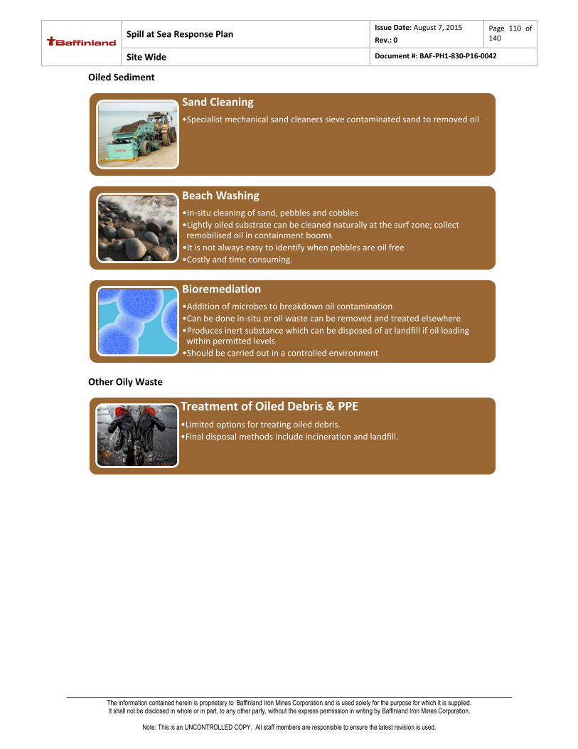
Spill at Sea Response Plan Issue Date: August 7, 2015
Rev.: 0
Page 110 of 140
Site Wide Document #: BAF-PH1-830-P16-0042
The information contained herein is proprietary to Baffinland Iron Mines Corporation and is used solely for the purpose for which it is supplied. It shall not be disclosed in whole or in part, to any other party, without the express permission in writing by Baffinland Iron Mines Corporation.
Note: This is an UNCONTROLLED COPY. All staff members are responsible to ensure the latest revision is used.
Oiled Sediment
Other Oily Waste
Sand Cleaning
•Specialist mechanical sand cleaners sieve contaminated sand to removed oil
Beach Washing
•In-situ cleaning of sand, pebbles and cobbles
•Lightly oiled substrate can be cleaned naturally at the surf zone; collect remobilised oil in containment booms
•It is not always easy to identify when pebbles are oil free
•Costly and time consuming.
Bioremediation
•Addition of microbes to breakdown oil contamination
•Can be done in-situ or oil waste can be removed and treated elsewhere
•Produces inert substance which can be disposed of at landfill if oil loading within permitted levels
•Should be carried out in a controlled environment
Treatment of Oiled Debris & PPE
•Limited options for treating oiled debris.
•Final disposal methods include incineration and landfill.

Spill at Sea Response Plan Issue Date: August 7, 2015
Rev.: 0
Page 111 of 140
Site Wide Document #: BAF-PH1-830-P16-0042
The information contained herein is proprietary to Baffinland Iron Mines Corporation and is used solely for the purpose for which it is supplied. It shall not be disclosed in whole or in part, to any other party, without the express permission in writing by Baffinland Iron Mines Corporation.
Note: This is an UNCONTROLLED COPY. All staff members are responsible to ensure the latest revision is used.
5 SPILL RESPONSE IN ICE
Resources Available
Safety
Personnel should observe safety considerations for working on ice in extreme cold weather.
Personnel should not attempt to access the ice in broken ice conditions. All access must be from vessels
Identify risks and mitigate them where possible
Communicate any risks and controls in place through a pre-operation safety brief
Wear the appropriate Personal Protective Equipment (PPE) including: three layers (base layer,
insulating middle layer and waterproof outer layer); insulated underwear, overalls, footwear,
gloves and hard hat liner; tinted safety specs; ice spikes.
Assess the ice to ensure it is thick enough to support responders and equipment.
Key Steps
•Vessel SOPEP equipmentTier 1•Shoreline Response Package
•Spill Response Vessel x 2 (Tug Boats)
•Work Boat x 2
•Line Boats x 2
Tier 2
•OSRLTier 3

Spill at Sea Response Plan Issue Date: August 7, 2015
Rev.: 0
Page 112 of 140
Site Wide Document #: BAF-PH1-830-P16-0042
The information contained herein is proprietary to Baffinland Iron Mines Corporation and is used solely for the purpose for which it is supplied. It shall not be disclosed in whole or in part, to any other party, without the express permission in writing by Baffinland Iron Mines Corporation.
Note: This is an UNCONTROLLED COPY. All staff members are responsible to ensure the latest revision is used.
STEP 1 – PREPARE: COMMUNICATIONS
Effective communication can enhance operation success.
Ineffective communication can lead to unsafe situations and accidents.
STEP 1 – PREPARE: FIND THE OIL
Resources that could be used to find oil include:
Side-Looking Airborne Radar (SLAR)
Satellite-based Synthetic Aperture Radar (SAR)
Aircraft and vessel-based Forward Looking Infrared (FLIR)
Trained dogs
Ground Penetrating Radar (GPR) operated from helicopters and/or ice surface
STEP 2 – CONTAIN THE OIL: OIL ON ICE AND SNOW
Berms, dikes and dams
Contain spilled oil, limit spreading and accumulate oil for recovery.
Contain and stabilise a contaminated area.
Contain or divert oil on water, or oil that has potential to migrate.
Use natural depressions to contain oil for recovery.
May need to incorporate flow regulation, such as a weir or spill way.
Use an impermeable lining on permeable surfaces.
Construct from readily available materials such as:
Earth
Gravel
Snow
Sandbags
Oil boom
Timber
Can damage the environment so obtain
appropriate approvals beforehand
• Emergency contacts
• Names of assets deployed, call signs & radio frequencies
Communications Plan
Snow Berm

Spill at Sea Response Plan Issue Date: August 7, 2015
Rev.: 0
Page 113 of 140
Site Wide Document #: BAF-PH1-830-P16-0042
The information contained herein is proprietary to Baffinland Iron Mines Corporation and is used solely for the purpose for which it is supplied. It shall not be disclosed in whole or in part, to any other party, without the express permission in writing by Baffinland Iron Mines Corporation.
Note: This is an UNCONTROLLED COPY. All staff members are responsible to ensure the latest revision is used.
Pits, trenches and slots
Contain oil and aid in its recovery. Excavate a depression or opening in a down-slope/down-current location
from the spill into which the oil will pool.
Contain or divert oil on water or oil that has potential to
migrate.
Use natural topography and hydrology to move the oil
to the collection point.
Use flushing to help collection.
Stack ice blocks from the trench next to it for added
safety and containment.
Enhance trenches by freezing standard skirt oil boom
into them; this effectively creates a berm and recovery
pit.
Obtain appropriate approvals before excavating.
Investigate subsurface obstacles before starting work.
STEP 2 – CONTAIN THE OIL: OIL UNDER ICE AND SNOW
Slots
Use a chainsaw or auger to cut a slot through the ice
to create a void for the oil to allow oil to pool on the
water surface for recovery or in situ burning.
Configure slots according to the operating
environment, oil type, weathering state, ice type and
equipment availability.
Cut slot at an angle and insert plywood to aid containment.
>0.5 knot current is generally required to move oil under the ice cover. Oil will collect in air pockets
under the ice if the current is slow. Slots can be cut above these air pockets.
Predict the oil flow direction and cut slots to intercept the flow.
Place insulating material, such as snow, on a growing ice sheet to create a pocket under the ice in
which oil can collect.

Spill at Sea Response Plan Issue Date: August 7, 2015
Rev.: 0
Page 114 of 140
Site Wide Document #: BAF-PH1-830-P16-0042
The information contained herein is proprietary to Baffinland Iron Mines Corporation and is used solely for the purpose for which it is supplied. It shall not be disclosed in whole or in part, to any other party, without the express permission in writing by Baffinland Iron Mines Corporation.
Note: This is an UNCONTROLLED COPY. All staff members are responsible to ensure the latest revision is used.
Bubbling techniques
In Ports and Harbours use a compressor to clear a hole in the ice to enable recovery of oil.
STEP 3 - RECOVER THE OIL
Surveillance
Airborne Surveillance
•Effective in identifying the presence of oil on water when supplemented with visual observations from trained observers.
•Side Looking Airborne Radar (SLAR) helps overcome problems of poor weather conditions and darkness.
•Use of existing airborne sensors can detect and map oil among ice in some situations, but capabilities are not yet proven.
Remote Sensing
•Synthetic Aperture Radar (SAR) satellite systems are not affected by darkness or poor visibility.
•Provides high spatial resolution imagery.
•Useito document changing ice conditions in the vicinity of the spill.
Tracking
•Tracking buoys can monitor the direction and progress of oil.
•In-country oceanographic and meteorological services can predict the movement of oil using weather patterns.
Surface Surveillance
•Deploy surveillance systems at the water’s surface (by vessel) or from the surface of the ice.
•Ground-penetrating radar (GPR) uses radar pulses to image the subsurface to detect changes in material, and can be deployed on the ice surface and from aircraft platforms.
•Trained dogs are reliable in identifying small oil spills in snow and on ice.

Spill at Sea Response Plan Issue Date: August 7, 2015
Rev.: 0
Page 115 of 140
Site Wide Document #: BAF-PH1-830-P16-0042
The information contained herein is proprietary to Baffinland Iron Mines Corporation and is used solely for the purpose for which it is supplied. It shall not be disclosed in whole or in part, to any other party, without the express permission in writing by Baffinland Iron Mines Corporation.
Note: This is an UNCONTROLLED COPY. All staff members are responsible to ensure the latest revision is used.
Skimmers
Skimmers have a pump rating. This is based on test tank conditions and does not reflect offshore recovery
operations. Rated pumping volume will rarely be achieved in field conditions.
Use skimmers designed to skim in ice conditions or modify non-specialist equipment.
Use hydraulic oil suitable for cold temperature.
Store equipment in heated stores or keep running to prevent freezing.
STEP 4 – RECORD AND REPORT
Repeat surveys throughout cleanup operations to assess progress and inform the operations team if the
cleanup strategy needs to be changed. Refer to: Appendix 2, FormsError! Reference source not found..
Record and report the following data to the ICC:
Time, date and location of survey
Shoreline features, such as access and potential lay down areas
Treatment recommendations
Oleophilic
Pro
Less water collected compared to other types of skimmers
Rope mop systems can be particularly useful in
ice-infested waters
Con
Ineffective in some emulsified oil
Oil will not adhere to the oleophillic surface if
dispersant has been used
Weir
Pro
Effective on higher viscosity oil than the oleophillic skimmer
Con
Sensitive to weather conditions; tend to
recover a high proportion of water
Debris in the water may block the hopper
and pump

Spill at Sea Response Plan Issue Date: August 7, 2015
Rev.: 0
Page 116 of 140
Site Wide Document #: BAF-PH1-830-P16-0042
The information contained herein is proprietary to Baffinland Iron Mines Corporation and is used solely for the purpose for which it is supplied. It shall not be disclosed in whole or in part, to any other party, without the express permission in writing by Baffinland Iron Mines Corporation.
Note: This is an UNCONTROLLED COPY. All staff members are responsible to ensure the latest revision is used.
6 SPILL RESPONSE IN BROKEN ICE
Resources Available
Safety
Personnel should observe safety considerations for Error! Reference source not found.working on ice in extreme cold
weather.
Personnel should not attempt to access the ice in broken ice conditions. All access must be from vessels
General Considerations
Seek expert advice at the earliest opportunity following a spill in significant ice.
Response strategies frequently involve moving ice; changes in ice concentration due to wind shift are
likely and may be large.
There may be no feasible response option if oil is widely distributed within a broken ice field.
Oil solidifies on the water’s surface if ambient temperature is below that of the oil’s pour point; this
makes traditional recovery techniques inefficient.
Oil can become mixed or encapsulated in ice, especially during late freeze up; in this scenario the
preferred strategy is monitor and evaluate.
Skimmers are most efficient when positioned in open water or leads between ice pieces.
Oleophillic skimmers such as suspended vertical rope mops, drum, brush and disk skimmers are the
most efficient and least likely to get clogged by ice.
•Vessel SOPEP equipmentTier 1•Spill Response Vessel x 2 (Tug Boats)
•skimmer
•Work Boats x 2
•Line Boats x2
•Shore line Response equipment
Tier 2
•OSRLTier 3

Spill at Sea Response Plan Issue Date: August 7, 2015
Rev.: 0
Page 117 of 140
Site Wide Document #: BAF-PH1-830-P16-0042
The information contained herein is proprietary to Baffinland Iron Mines Corporation and is used solely for the purpose for which it is supplied. It shall not be disclosed in whole or in part, to any other party, without the express permission in writing by Baffinland Iron Mines Corporation.
Note: This is an UNCONTROLLED COPY. All staff members are responsible to ensure the latest revision is used.
Techniques
Containment and Recovery
Techniques for ice coverage up to 25-30% are much the same as those employed in open water (see
section 4)
Equipment may need to be adapted for use at ambient temperature
o Different grades of oil and fluids
o Equipment controls useable with gloved hands
Greater than 25 - 30% ice cover
o Booms become of little or no use (Owens, et al., 1998)
o Ice class vessels are required to take skimmers to the oil
o Recovery rates are typically low, 1-20% (Harvey Consulting, 2009)
Greater than 70% ice cover
o Natural containment by ice
o Ice breakers are required to access the oil
o Recovery rates are low

Spill at Sea Response Plan Issue Date: August 7, 2015
Rev.: 0
Page 118 of 140
Site Wide Document #: BAF-PH1-830-P16-0042
The information contained herein is proprietary to Baffinland Iron Mines Corporation and is used solely for the purpose for which it is supplied. It shall not be disclosed in whole or in part, to any other party, without the express permission in writing by Baffinland Iron Mines Corporation.
Note: This is an UNCONTROLLED COPY. All staff members are responsible to ensure the latest revision is used.
7 SPILL RESPONSE UNDER ICE
Resources Available
Safety
Personnel should observe safety considerations for working on ice in extreme cold weather.
General Considerations
Seek expert advice at the earliest opportunity following a spill on ice.
Oil solidifies on the water’s surface if ambient temperature is below that of the oil’s pour point; this
makes traditional recovery techniques inefficient.
Spilled oils can remain unweathered for several months, this can help the response.
Equipment should be of an appropriate design and specification for the extreme conditions.
Fuels and lubricants should be suitable for the ambient temperature to prevent waxing.
Engines will usually run continuously. Pre-plan fuel, lubricant and spare parts.
Provide a warm refuge with hot food and drinks.
•Vessel SOPEP equipmentTier 1
•Spill Response Vessel x 2 (Tug Boats)
•skimmer
•Shore line Response Package
•Work boat x 2
•Line Boat x 2
Tier 2
•OSRLTier 3

Spill at Sea Response Plan Issue Date: August 7, 2015
Rev.: 0
Page 119 of 140
Site Wide Document #: BAF-PH1-830-P16-0042
The information contained herein is proprietary to Baffinland Iron Mines Corporation and is used solely for the purpose for which it is supplied. It shall not be disclosed in whole or in part, to any other party, without the express permission in writing by Baffinland Iron Mines Corporation.
Note: This is an UNCONTROLLED COPY. All staff members are responsible to ensure the latest revision is used.
Techniques
Currents that exceed 1 m/s may prevent successful containment, recovery and burning.
Cut slots into the ice using a chainsaw or auger to allow the oil to
pool on the water surface for recovery or in situ burning.
If water is flowing faster than 0.4 m/s ice slots should be angled to
prevent the oil from flowing past beneath them.
Place insulating material, such as snow, on a growing ice sheet to
create a pocket under the ice in which oil can collect.
Booms or sheets of metal, plastic or wood can be placed in the ice
slots on the opposite side to the current flow to create a subsurface
barrier, encouraging the oil to the surface and preventing further
spreading.

Spill at Sea Response Plan Issue Date: August 7, 2015
Rev.: 0
Page 120 of 140
Site Wide Document #: BAF-PH1-830-P16-0042
The information contained herein is proprietary to Baffinland Iron Mines Corporation and is used solely for the purpose for which it is supplied. It shall not be disclosed in whole or in part, to any other party, without the express permission in writing by Baffinland Iron Mines Corporation.
Note: This is an UNCONTROLLED COPY. All staff members are responsible to ensure the latest revision is used.
8 SHORELINE CLEANUP ASSESSMENT TECHNIQUE (SCAT)
Resources Available
Safety
Shoreline conditions and composition can vary significantly. Ensure you are familiar with the local
conditions and environment. Always consider; access, egress, tidal patterns, load bearing capacity
Wear the appropriate Personal Protective Equipment (PPE)
Identify risks and mitigate them where possible
Communicate any risks and controls in place through a pre-survey safety brief
Ensure full safety protocols are followed before conducting SCAT surveys
Key Steps
• OSRL Spill Response SpecialistsTier 3

Spill at Sea Response Plan Issue Date: August 7, 2015
Rev.: 0
Page 121 of 140
Site Wide Document #: BAF-PH1-830-P16-0042
The information contained herein is proprietary to Baffinland Iron Mines Corporation and is used solely for the purpose for which it is supplied. It shall not be disclosed in whole or in part, to any other party, without the express permission in writing by Baffinland Iron Mines Corporation.
Note: This is an UNCONTROLLED COPY. All staff members are responsible to ensure the latest revision is used.
Step 1 – Prepare: Organise Operations
Effective communication is required for consistency and information flow to incident command.
SCAT operations fall under the Environment Planning Team. The SCAT Coordinator could have a SCAT Technical Advisor, SCAT Logistics, SCAT Operations Liaison, SCAT Team Leaders and SCAT Database Coordinator in the structure.
STEP 1 – PREPARE: THE SCAT SURVEY TEAM
A basic briefing is required before any field activities are carried out by the SCAT team(s) to ensure systematic
and consistent results.
Consideration should always be given to; the extent and duration of environmental impact if the oil is not
removed, natural removal rates, potential for remobilised oil to affect other sensitive resources, and likelihood
of clean-up to cause greater harm than oil alone.
• Emergency contacts and procedures
• Names of assets deployed, call signs and radio frequencies
Communications Plan
SCAT Briefing Agenda
•Health, safety and welfare issues
•Allocation of segments to be surveyed
•Communications and reporting channels
•Distribution of maps, assessment forms and guidance
•Check field equipment and supplies
•Assessment methodology understood by all team members
Pre-Survey Standardisation
•If there are multiple teams and to ensure a high degree of consistency and calibration between them, have a pre-survey session to focus on:
• terminology of oiling characteristics
• shoreline types
• standard definitions

Spill at Sea Response Plan Issue Date: August 7, 2015
Rev.: 0
Page 122 of 140
Site Wide Document #: BAF-PH1-830-P16-0042
The information contained herein is proprietary to Baffinland Iron Mines Corporation and is used solely for the purpose for which it is supplied. It shall not be disclosed in whole or in part, to any other party, without the express permission in writing by Baffinland Iron Mines Corporation.
Note: This is an UNCONTROLLED COPY. All staff members are responsible to ensure the latest revision is used.
STEP 1 – PREPARE: SEGMENTATION
The first step of a SCAT survey is to divide the coastline into working units called segments, within which the
shoreline character is relatively uniform in terms of physical features and sediment type.
• Segmentation is the basis for development of treatment plans
• Boundaries between segments are geological features or change in shoreline type, oiling conditions, river mouths or jurisdictional
• Satellite images, charts and sensitivity maps may assist in defining shorelines
• Segment lengths are 0.2 - 2km, or as access allows.
Principles of Segmentation
• Distinct along-shore sections of shoreline that can be used as operational units
• Relatively homogeneous physical features or sediment type
• Identified by a unique location code
• Bounded by prominent geological or operational features, or by changes in shoreline type, substrate, or oiling conditions
Segment Characteristics
• Sub-segments are created if along-shore oiling conditions vary significantly within a pre-designated segment
• Along-shore oiling conditions change throughout time within a segment during a spill incident
• If there is an operational division boundary within a segment
• Segment lengths are small enough to obtain adequate resolution and detail on the distribtion of oil, but not so small that too much data is generated
Sub-Segmentation

Spill at Sea Response Plan Issue Date: August 7, 2015
Rev.: 0
Page 123 of 140
Site Wide Document #: BAF-PH1-830-P16-0042
The information contained herein is proprietary to Baffinland Iron Mines Corporation and is used solely for the purpose for which it is supplied. It shall not be disclosed in whole or in part, to any other party, without the express permission in writing by Baffinland Iron Mines Corporation.
Note: This is an UNCONTROLLED COPY. All staff members are responsible to ensure the latest revision is used.
STEP 2 – CONDUCT SHORELINE SURVEY: SOS FORM
Shoreline Oiling Summary (SOS) Forms must be completed for each segment.
General Information
Survey Team
Define Segment
Define Shoreline
Operational Features
Describe Surface Oiling
Describe Subsurface
Oiling
Photos and
Sketches
SOS FORM
Needed for Data Management:
Incident Name, Survey Type,
Segment -ID, Survey Time, Weather
All survey team members’,
affiliations and contact
numbers should be
entered.
The total length and
length surveyed should be
entered (most cases these
will be the same).
Longitude and latitude
recorded for the start and
finish of each segment.
It is important to identify the nature of
the shoreline types within the segment,
paying particular attention to the oiled
areas.
Operational features will assist decision makers and logistics or
operational personnel in making an initial evaluation of the viable options
for clean up activity.
Access information, debris and ongoing clean up should be captured.
Detailed recording of oiled
areas is important. The form
requires quantitative
measurement of oiled zones.
The presence of subsurface
(buried) oil can only be
revealed by digging trial pits
or trenches in the shoreline.
Photos and sketches are very useful to
document the appearance of the shore.

Spill at Sea Response Plan Issue Date: August 7, 2015
Rev.: 0
Page 124 of 140
Site Wide Document #: BAF-PH1-830-P16-0042
The information contained herein is proprietary to Baffinland Iron Mines Corporation and is used solely for the purpose for which it is supplied. It shall not be disclosed in whole or in part, to any other party, without the express permission in writing by Baffinland Iron Mines Corporation.
Note: This is an UNCONTROLLED COPY. All staff members are responsible to ensure the latest revision is used.
STEP 2 – CONDUCT SHORELINE SURVEY: DEFINE THE SHORELINE
It is important to identify the nature of the shoreline types within the whole segment, paying particular
attention to oiled areas.
STEP 2 – CONDUCT SHORELINE SURVEY: DEFINE SURFACE OIL
Making a detailed record of oiled areas is important. The SOS form requires some quantitative measurement
of oiled zones. Surface oil is defined as oil that is visible on the surface and up to 5 cm below the surface of
sandy beaches.
• Identify all notable shoreline types within the segment
• Select one primary shoreline type for both intertidal and supratidal zones
• There can be several secondary shoreline types within a segment.
• Shoreline types are based on the Environmental Sensitivity Index (ESI) values.
Shoreline Type
• Identify sediment type based on sediment size
• Boulder, cobble, pebble, granule, sand, silt and clay
Sediment Type
• Define the exposure rating of the upper shore parts of the segment
• Very exposed, exposed, very sheltered, partially sheltered
Wave Exposure
Is surface oil present?
Yes - go to Step 1
No - "tick no oil observed" box
STEP 1
Identify oiled zones, give a description of
oiling conditions.
Give each zone an ID
STEP 2
Define each zone
(position, oil cover, distribution,
thickness and character)
STEP 3
Annotate map and/or draw sketch
map with location of oiled zone(s).

Spill at Sea Response Plan Issue Date: August 7, 2015
Rev.: 0
Page 125 of 140
Site Wide Document #: BAF-PH1-830-P16-0042
The information contained herein is proprietary to Baffinland Iron Mines Corporation and is used solely for the purpose for which it is supplied. It shall not be disclosed in whole or in part, to any other party, without the express permission in writing by Baffinland Iron Mines Corporation.
Note: This is an UNCONTROLLED COPY. All staff members are responsible to ensure the latest revision is used.
STEP 2 – CONDUCT SHORELINE SURVEY: DEFINE SUBSURFACE OIL
Dig a pit or trench to identify presence of subsurface (buried) oil, if the substrate is penetrable.
STEP 2 – CONDUCT SHORELINE SURVEY: SKETCHES AND PHOTOGRAPHS
Field sketches allow more detail on the location of the oil to be captured. Photographs help to illustrate the
distribution and extent of oiling, the location and character of the affected areas, the location of any puts,
potentially sensitive resources, access points, possible laydown areas and the shoreline response.
Has subsurface
oil been investigated
?
Yes - go to Step 1
No - "tick no investigation" box
STEP 1
Give each pit an ID
STEP 2
Define each pit
(position, depth, oiled zone depth,
character and water table depth)
STEP 3
Annotate map and/or draw sketch
map with location of pit(s).
Sketches
• north arrow
• segment number
• scale
• segment boundaries
• water levels
• major features and landmarks
Photographs
• set time and date
• capture a scale bar
• mark location of photograph and direction on sketch
• record photograph number on SOS form

Spill at Sea Response Plan Issue Date: August 7, 2015
Rev.: 0
Page 126 of 140
Site Wide Document #: BAF-PH1-830-P16-0042
The information contained herein is proprietary to Baffinland Iron Mines Corporation and is used solely for the purpose for which it is supplied. It shall not be disclosed in whole or in part, to any other party, without the express permission in writing by Baffinland Iron Mines Corporation.
Note: This is an UNCONTROLLED COPY. All staff members are responsible to ensure the latest revision is used.
STEP 3 – RECORD AND REPORT
Recording and reporting during shoreline surevys is integral to the SCAT process. After data collection occurs,
it must be collated and analysed so recommendations for clean-up can be made.
Completed SOS Forms and data collected by SCAT Teams needs to be made available quickly to decision
makers. Data management system requirements will depend on the size of the incident.

Spill at Sea Response Plan Issue Date: August 7, 2015
Rev.: 0
Page 127 of 140
Site Wide Document #: BAF-PH1-830-P16-0042
The information contained herein is proprietary to Baffinland Iron Mines Corporation and is used solely for the purpose for which it is supplied. It shall not be disclosed in whole or in part, to any other party, without the express permission in writing by Baffinland Iron Mines Corporation.
Note: This is an UNCONTROLLED COPY. All staff members are responsible to ensure the latest revision is used.
9 WASTE MANAGEMENT
Resources Available
Safety
Wear the appropriate Personal Protective Equipment (PPE)
Identify risks and mitigate them where possible
Communicate any risks and controls in place through a pre-operation safety brief
Key Steps
•On board storageTier 1
•Fasttanks
•Drums
•Vacuum Trucks
•Inflatable Barge
Tier 2
•OSRL
•Third party contractor vesselsTier 3

Spill at Sea Response Plan Issue Date: August 7, 2015
Rev.: 0
Page 128 of 140
Site Wide Document #: BAF-PH1-830-P16-0042
The information contained herein is proprietary to Baffinland Iron Mines Corporation and is used solely for the purpose for which it is supplied. It shall not be disclosed in whole or in part, to any other party, without the express permission in writing by Baffinland Iron Mines Corporation.
Note: This is an UNCONTROLLED COPY. All staff members are responsible to ensure the latest revision is used.
STEP 2 – PREPARE: STORAGE IDENTIFICATION AND WORKFORCE ORIENTATION
Use the waste hierarchy to manage the total amount of waste generated:
(Source: IPIECA, 2004)

Spill at Sea Response Plan Issue Date: August 7, 2015
Rev.: 0
Page 129 of 140
Site Wide Document #: BAF-PH1-830-P16-0042
The information contained herein is proprietary to Baffinland Iron Mines Corporation and is used solely for the purpose for which it is supplied. It shall not be disclosed in whole or in part, to any other party, without the express permission in writing by Baffinland Iron Mines Corporation.
Note: This is an UNCONTROLLED COPY. All staff members are responsible to ensure the latest revision is used.
Organise waste storage:
Identify storage facilities for every stage of the response, from recovery to long term storage,
treatment and/or disposal.
Consider the use of staged storage facilities to minimise cross-contamination.
Consult stakeholders (local authorities, government) to identify suitable locations of
intermediate and long term storage sites.
Establish waste minimisation guidelines with workforce and instruct in the proper use of
equipment and storage facilities

Spill at Sea Response Plan Issue Date: August 7, 2015
Rev.: 0
Page 130 of 140
Site Wide Document #: BAF-PH1-830-P16-0042
The information contained herein is proprietary to Baffinland Iron Mines Corporation and is used solely for the purpose for which it is supplied. It shall not be disclosed in whole or in part, to any other party, without the express permission in writing by Baffinland Iron Mines Corporation.
Note: This is an UNCONTROLLED COPY. All staff members are responsible to ensure the latest revision is used.
STEP 3 – REDUCE WASTE: SITE SET-UP AND HOUSEKEEPING
Components of oily waste produced from a response operation
Temporay Storage Facilities will:
•Prevent delays resulting from many vehicles trying to access one site.
•Allow time to organise final disposal sites or methods whilst the response effort continues.
•Assist in appropriate waste segregation.
Considerations:
•Local, regional and national legal regulations.
•Waste should be labelled with type and source of waste.
•The site set up should allow for waste separation to minimise secondary contamination.
Waste Sites Should:
•Be fenced off with controlled site access.
•Have good access and egress.
Storage Containers Should:
•Be suitable for the waste type.
•Have useful and appropriate signage to reflect the site set up.
•Be water tight and lined with polyethylene sheeting to prevent oil leaching.

Spill at Sea Response Plan Issue Date: August 7, 2015
Rev.: 0
Page 131 of 140
Site Wide Document #: BAF-PH1-830-P16-0042
The information contained herein is proprietary to Baffinland Iron Mines Corporation and is used solely for the purpose for which it is supplied. It shall not be disclosed in whole or in part, to any other party, without the express permission in writing by Baffinland Iron Mines Corporation.
Note: This is an UNCONTROLLED COPY. All staff members are responsible to ensure the latest revision is used.
Shoreline/Inland
Pre-clean beach/bank sections at risk of contamination before oil impacts to reduce oily waste.
Block drainage points, if present, which could transfer oil beyond the immediate site.
If beach/bank has been impacted, minimise contamination by using a defined site set-up (below).
Contain and recover pollution as close to the source as possible.
Minimise the use of sorbents and re-use PPE where possible.
Store shoreline response resources above high water mark and on level surfaces.
A wide variety of options can be employed for storage onshore; cover and line storage containers.
Site Set-Up
Hot Zone: Oiled work area, all oil stays in this zone.
Warm Zone (Decontamination Zone): Clean down area; use
one entrance/exit channel. Anyone leaving must pass through
an organised decontamination process here.
Cold Zone: Waste removal vehicles collect full containers from
this clean area so that they do not spread oil onto the roads.
Offshore
Prepare sufficient temporary onboard waste storage to
last operational period.
Consider the use of inflatable barges, heated tanks and vessel storage tanks.
Arrange intermediate storage or bulking facility for remote response operations, particularly if more
than one vessel is recovering oil.
Follow work zone arrangement on vessel of opportunity to prevent secondary contamination. Set up
defined areas (hot, warm and cold zones) if vessel lacks defined work zones.
Minimise the use of sorbents, re-use PPE where possible.
Housekeeping
Secondary contamination is the spread of oil via transport, people and equipment to unpolluted areas.
Avoid secondary contamination with good housekeeping:
Regularly check pumps and hose connections for leaks
Ensure all storage is water-tight and oil-proof to prevent leakage
Cover waste containers to prevent rainwater increasing the waste volume
Line and decontaminant all waste transportation vehicles before leaving site
Establish a traffic circulation plan for vehicles
Locate waste storage sites close to recovery equipment

Spill at Sea Response Plan Issue Date: August 7, 2015
Rev.: 0
Page 132 of 140
Site Wide Document #: BAF-PH1-830-P16-0042
The information contained herein is proprietary to Baffinland Iron Mines Corporation and is used solely for the purpose for which it is supplied. It shall not be disclosed in whole or in part, to any other party, without the express permission in writing by Baffinland Iron Mines Corporation.
Note: This is an UNCONTROLLED COPY. All staff members are responsible to ensure the latest revision is used.
Types of waste produced by each response technique Technique Waste collected Waste generated
Off
sho
re
Re
spo
nse
Natural Recovery - -
Containment and
Recovery
Oil and emulsified oil
Contaminated water
Contaminated debris
Contaminated boom and skimmer equipment
Contaminated vessel
Sho
relin
e a
nd
Inla
nd
Re
spo
nse
Sediment Relocation - Contaminated equipment (spade, bags) & PPE
Manual Recovery Oil and oiled sediment (tarballs,
emulsified oil)
Oiled debris & vegetation
Contaminated equipment (spades, buckets)
PPE
Sorbents Oil Sorbents, PPE
Mechanical Recovery Oil and oiled sediment Contaminated equipment (skimmers, pumps) &
PPE
Flushing Remobilised oil Sorbents and/or containment boom & PPE
STEP 4 - REUSE: SEGREGATE
Segregation is the first step to reusing and recycling waste.
Waste should be classified, segregated and labelled. Segregate different types of oiled waste and keep non-
oiled waste separate.
Refer to: The relevant response technique for the most effective method of removal.
Consider the following to reuse or segregate different types of waste generated
Oiled waste Considerations
Fluid oil Feasibility of using recovered oil as a raw material or low grade fuel
Prevent water or debris entering waste oil containers (consider decanting)
Use cleaners and wash sparingly with water
Heavily contaminated oil Discharge into lined lagoons, pits or large open topped tanks
Separate oil, water and oiled debris; pre-treat if possible.
Solid waste (includes oiled debris
and response material)
Do not mix oiled waste with domestic/non-oiled waste
Prevent oily wastes from contaminating soil; use liners
Use sorbent pads until they become moderately oiled
Minimise collection of underlying, non-oiled sediment
Clean and re-use recovery equipment (e.g. pom-poms) rather than discarding
Oiled wildlife Keep dead animals separate from other waste types to prevent spread of disease

Spill at Sea Response Plan Issue Date: August 7, 2015
Rev.: 0
Page 133 of 140
Site Wide Document #: BAF-PH1-830-P16-0042
The information contained herein is proprietary to Baffinland Iron Mines Corporation and is used solely for the purpose for which it is supplied. It shall not be disclosed in whole or in part, to any other party, without the express permission in writing by Baffinland Iron Mines Corporation.
Note: This is an UNCONTROLLED COPY. All staff members are responsible to ensure the latest revision is used.
STEP 5 - RECYCLE: PRE-TREAT
Pre-treat waste in situ to reduce the amount of waste that needs to be transported and treated. Pre-treat by:
surf washing
burning
sand sieving
bioremediation
STEP 6 – DISPOSE
Initial transportation will involve small vehicles such as dump trucks and front end loaders. Subsequent
transportation to intermediate or final disposal sites can include tankers for liquid waste and sealed trucks for
solid waste.
Ensure the following:
Trucks have a covered or sealed top
Trucks are decontaminated before leaving the site
Waste shipments meet regulations
Document and retain consignment notes for
all waste leaving the site
waste being transferred from an intermediate storage site to a final suitably licensed
disposal/treatment site
Disposal options depend on volume and type of oil, contaminated debris volume, spill location
(offshore/shoreline), environmental and legal considerations, practical limitations and cost.

Spill at Sea Response Plan Issue Date: August 7, 2015
Rev.: 0
Page 134 of 140
Site Wide Document #: BAF-PH1-830-P16-0042
The information contained herein is proprietary to Baffinland Iron Mines Corporation and is used solely for the purpose for which it is supplied. It shall not be disclosed in whole or in part, to any other party, without the express permission in writing by Baffinland Iron Mines Corporation.
Note: This is an UNCONTROLLED COPY. All staff members are responsible to ensure the latest revision is used.
Oil-Water Separation
•Use an onboard oil-water separator to reduce contaminated waste quantities going to final disposal.
•The oil/water residue from separation should meet 15 ppm discharge standards for release into the environment.
Emulsion Breaking
•Waste emulsion can be broken down into its constituent parts of oil and water using a specialised emulsion breaking chemical.
•Oil can then be sent for refining. The emulsion breaking chemicals remain in the water which has to be disposed of appropriately.
Re-Processing
•Treatment of recovered liquid waste.
•Oil is reprocessed through an oil refinery or recycling plant.
•Oil with a high salt content may corrode refinery pipe work.
•Only debris free oil or an oil/water mix can be processed.
Incineration
•Treatment of recovered liquid waste.
•Small portable incinerators must be permitted by the Regulator prior to use.
•High salt content in the oil may render this option unsuitable.
•Costly option (environmentally and economically).
•Facilities are uncommon and are unable to deal with large quantities.
Land Fill
•Treatment of other oily waste (debris/PPE).
•If waste contains approximately 5% oil it can usually be disposed of with general waste, however local and national regulations should always be adhered to.
•Chemical testing required to determine hazardous content.
•Facilities able to receive this type of waste are limited.

Spill at Sea Response Plan Issue Date: August 7, 2015
Rev.: 0
Page 135 of 140
Site Wide Document #: BAF-PH1-830-P16-0042
The information contained herein is proprietary to Baffinland Iron Mines Corporation and is used solely for the purpose for which it is supplied. It shall not be disclosed in whole or in part, to any other party, without the express permission in writing by Baffinland Iron Mines Corporation.
Note: This is an UNCONTROLLED COPY. All staff members are responsible to ensure the latest revision is used.
Sand Cleaning
•Treatment of oiled sediment
•Specialist mechanical sand cleaners sieve contaminated sand to removed oil
•Consider NEBA to prevent damage by over cleaning or sterilisation
Beach Washing
•In-situ cleaning of sand, pebbles and cobbles
•Lightly oiled substrate can be cleaned naturally at the surf zone; collect remobilised oil in containment booms
•It is not always easy to identify when pebbles are oil free
•Produces oily water requiring treatment - costly and time consuming.
Bioremediation
•Treatment of oiled sediment
•Addition of microbes to breakdown oil contamination
•Can be done in-situ or oil waste can be removed and treated elsewhere
•Produces inert substance which can be disposed of at landfill if oil loading within permitted levels
•Should be carried out in a controlled environment

Spill at Sea Response Plan Issue Date: August 7, 2015
Rev.: 0
Page 136 of 140
Site Wide Document #: BAF-PH1-830-P16-0042
The information contained herein is proprietary to Baffinland Iron Mines Corporation and is used solely for the purpose for which it is supplied. It shall not be disclosed in whole or in part, to any other party, without the express permission in writing by Baffinland Iron Mines Corporation.
Note: This is an UNCONTROLLED COPY. All staff members are responsible to ensure the latest revision is used.
Appendix 4 - Environmental Information
This section highlights the key environmental information for the scope of the SSRP
Sea temperature
Sea temperature averages about 2° C through the area from Milne Inlet to Eclipse Sound, based on
HYCOM modelling (). From a conservative (less evaporation loss) view 1° C is selected for the spill
weathering.
FIGURE 9-1 HYCOM SEA TEMP
-0.3
-1.6
-1.0
0.00.3
-1.6
0.9
2.52.1
2.6 2.7
1.0
2.7
6.7
6.16.6
6.9
4.8
-2.0
0.0
2.0
4.0
6.0
8.0
2008 2009 2010 2011 2012 2013
9
Min of Tsea (°C) Average of Tsea (°C) Max of Tsea (°C)

Spill at Sea Response Plan Issue Date: August 7, 2015
Rev.: 0
Page 137 of 140
Site Wide Document #: BAF-PH1-830-P16-0042
The information contained herein is proprietary to Baffinland Iron Mines Corporation and is used solely for the purpose for which it is supplied. It shall not be disclosed in whole or in part, to any other party, without the express permission in writing by Baffinland Iron Mines Corporation.
Note: This is an UNCONTROLLED COPY. All staff members are responsible to ensure the latest revision is used.
Wind
Winds data for the area of operation using the following sources:
the met station at the Milne port site
Environment Canada climate stations at Pond Inlet
MSC North Atlantic wind and wave hindcast winds just east of the entrance to Pond Inlet
European Centre for Medium-Range Weather Forecasts (ECMWF), ERA Interim (ERAI) class, Atmospheric Model winds at 10 m, gridded over the study area
The data from these sources is shown in Figure 9-2.
FIGURE 9-2 WIND COMPARISON, SEPTEMBER 2007

Spill at Sea Response Plan Issue Date: August 7, 2015
Rev.: 0
Page 138 of 140
Site Wide Document #: BAF-PH1-830-P16-0042
The information contained herein is proprietary to Baffinland Iron Mines Corporation and is used solely for the purpose for which it is supplied. It shall not be disclosed in whole or in part, to any other party, without the express permission in writing by Baffinland Iron Mines Corporation.
Note: This is an UNCONTROLLED COPY. All staff members are responsible to ensure the latest revision is used.
Ocean Currents
Ocean currents are in Figure 9-3.
Figure 9-3: Milne Inlet, HYCOM Surface Mean Currents, September

Spill at Sea Response Plan Issue Date: August 7, 2015
Rev.: 0
Page 139 of 140
Site Wide Document #: BAF-PH1-830-P16-0042
The information contained herein is proprietary to Baffinland Iron Mines Corporation and is used solely for the purpose for which it is supplied. It shall not be disclosed in whole or in part, to any other party, without the express permission in writing by Baffinland Iron Mines Corporation.
Note: This is an UNCONTROLLED COPY. All staff members are responsible to ensure the latest revision is used.
Area of local importance
During a workshop held by BIMC with attendance from; Oil Spill Response Limited (OSRL), AMEC,
Environment Canada, Transport Canada, Canadian Coast Guard, Fisheries and Oceans, Qikiqtani Inuit
Association, Pond Inlet Hunters and Trappers Association a number of areas of importance were
identified. These are shown in Figure 9-4 along with known natural collections points identified.
FIGURE 9-4 AREAS OF IMPORTANCE

Spill at Sea Response Plan Issue Date: August 7, 2015
Rev.: 0
Page 140 of 140
Site Wide Document #: BAF-PH1-830-P16-0042
The information contained herein is proprietary to Baffinland Iron Mines Corporation and is used solely for the purpose for which it is supplied. It shall not be disclosed in whole or in part, to any other party, without the express permission in writing by Baffinland Iron Mines Corporation.
Note: This is an UNCONTROLLED COPY. All staff members are responsible to ensure the latest revision is used.
Appendix 5 – Fuel Spill Modelling
For all modelling results refer to the Fuel Spill Modelling Report for Milne Inlet, Bruce Head, Eclipse Sound
and Pond Inlet conducted by AMEC on behalf of BIMC.