table contents - pumpworks.com … · table of contents introduction introduction intro‐2 safety...
TRANSCRIPT
Revision: 0

TABLE OF CONTENTS
Introduction
Introduction INTRO‐2 Safety INTRO‐3 Warranty INTRO‐4
Product Description General Description DESIGN‐2 Part Description DESIGN‐2,3 Nameplates DESIGN‐4,5 Figures Figure 1: PWA‐LF Pump DESIGN‐2 Figure 2: PWA‐LF Power End Cross Sectional DESIGN‐3 Figure 3: Pump Casing Nameplate – English DESIGN‐4 Figure 4: Pump Casing ID Tag DESIGN‐4 Figure 5: Pump Casing Nameplate – Metric DESIGN‐5 Figure 6: Bearing Frame Nameplate DESIGN‐5 Tables Table 1: Hydraulic Sizes by Group DESIGN‐2 Table 2: Pump Casing Parts DESIGN‐2 Table 3: Power End Main Parts DESIGN‐3 Table 4: Nameplate Description DESIGN‐4 Table 5: Casing Nameplate Definitions ‐ English DESIGN‐4 Table 6: Casing Nameplate Definitions ‐ Metric DESIGN‐5 Table 7: Power End Nameplate Definitions DESIGN‐5
Handling
Delivery Inspection HANDLE‐1 Transportation HANDLE‐2 Pump Handling HANDLE‐2 Lifting Methods HANDLE‐3,4,5 Storage HANDLE‐5 Pump Storage Requirements HANDLE‐5 Frost Proofing HANDLE‐6 Figures Figure 1: Bare Pump Lifting HANDLE‐3 Figure 2: Base Mounted Pump Lifting HANDLE‐3
Figure 3: Base Mounted Pump with Motor HANDLE‐4 Figure 4: Fab Base Mounted Pump with Motor HANDLE‐4
Figure 5: Bare Pump with Adapter Lifting HANDLE‐5 Tables Table 1: Lifting Methods HANDLE‐2 Table 2: Storage Requirements HANDLE‐5 Table 3: Frostproofing HANDLE‐6
Installation Pre‐installation INSTALL‐2 Pump Location Guidelines INSTALL‐2 Foundation Requirements INSTALL‐3 Baseplate Mounting Procedures INSTALL‐3 Install the Baseplate INSTALL‐3,4,5,6 Grout the baseplate INSTALL‐6,7 Install the pump, driver, and coupling INSTALL‐8 Pump‐to‐driver alignment INSTALL‐8 Alignment checks INSTALL‐8 Permitted indicator values for alignment checks INSTALL‐9 Alignment measurement guidelines INSTALL‐9 Attach the dial indicators for alignment INSTALL‐10 Pump‐to‐driver alignment instructions INSTALL‐10,11,12,13 Piping checklists INSTALL‐13 General piping checklist INSTALL‐14
Suction‐piping checklist INSTALL‐15,16,17 Discharge piping checklist INSTALL‐18,19
Figures Figure 1: Sleeve Type Bolts INSTALL‐2 Figure 2: J Type Bolts INSTALL‐3 Figure 3: Baseplate Top View INSTALL‐3 Figure 4: Baseplate Side View INSTALL‐4 Figure 5: Jackscrew Bolts INSTALL‐5 Figure 6: Leveling Baseplate – Motor Pads INSTALL‐5 Figure 7: Leveling Baseplate – Pump Pads INSTALL‐6 Figure 8: Initial Grout INSTALL‐6 Figure 9: Final Grout INSTALL‐7 Figure 10: Dial Indicator Alignment INSTALL‐9 Figure 11: Incorrect Vertical Alignment INSTALL‐10 Figure 12: Incorrect Horizontal Alignment INSTALL‐11 Figure 13: Correct Vertical Alignment INSTALL‐12 Figure 14: Correct Horizontal Alignment INSTALL‐12
Tables Table 1: Guidelines for Locations INSTALL‐2 Table 2: Alignment Checks INSTALL‐8 Table 3: Cold Alignment INSTALL‐8 Table 4: Hot Alignment INSTALL‐8 Table 5: Alignment Measurement Guidelines INSTALL‐9 Table 6: Angular Alignment for Vertical Corr. INSTALL‐10 Table 7: Angular Alignment for Horizontal Corr. INSTALL‐11 Table 8: Parallel Alignment for Vertical Corr. INSTALL‐11 Table 9: Parallel Alignment for Horizontal Corr. INSTALL‐12 Table 10: Piping Guidelines INSTALL‐14 Table 11: Suction Piping Guidelines INSTALL‐15,16 Table 12: Suction Piping Guidelines – Liq. Below INSTALL‐16 Table 13: Suction Piping Guidelines – Liq. Above INSTALL‐16 Table 14: Discharge Piping Guidelines INSTALL‐18
Commissioning, Startup, Operation and Shutdown
Preparation for Startup STARTUP‐2 Coupling Guard STARTUP‐2,3,4 Pump Rotation STARTUP‐4 Setting Impeller Clearance STARTUP‐5 PWA Standard Impeller Clearances STARTUP‐6 Dial Indicator Method STARTUP‐6 Feeler Gauge Method STARTUP‐7 Install Coupling STARTUP‐7 Install Coupling Guard STARTUP‐7‐11 Bearing Lubrication STARTUP‐11 Pump Priming STARTUP‐12,13,14 Start Up Precautions STARTUP‐15,16 Shut Down STARTUP‐16
Figures Figure 1: Guard Removal, Slide Driver Half STARTUP‐2 Figure 2: Guard Removal, Driver Side End Plate STARTUP‐3 Figure 3: Guard Removal, Driver Half STARTUP‐3 Figure 4: Guard Removal, Pump Half STARTUP‐4 Figure 5: Mounting Indicator STARTUP‐6 Figure 6: Setting Impeller Clearance STARTUP‐7 Figure 7: Required Guard Parts STARTUP‐8 Figure 8: Guard Install, Slide Pump Half STARTUP‐9 Figure 9: Guard Install, Slide Motor Half STARTUP‐10 Figure 10: Guard Install, Slide End Plate STARTUP‐10 Figure 11: Guard Install, Slide Motor Half to Fit STARTUP‐11 Figure 12: Power End – Lube Fill STARTUP‐12 Figure 13: Pump Priming – Supply Above Pump STARTUP‐13

TABLE OF CONTENTS
Figure 14: Pump Priming – Foot Valve STARTUP‐14 Figure 15: Pump Priming – Foot Valve and Bypass STARTUP‐14 Tables Table 1: Impeller Clearances STARTUP‐5 Table 2: Guard Installation Guidelines STARTUP‐8 Table 3: Lubrication Capacities STARTUP‐11 Table 4: Oil Requirements Based on Temperature STARTUP‐12 Table 5: Recommended Lubricants STARTUP‐12
Maintenance Schedule MAINT‐2 Bearings MAINT‐2 Lubrication Requirements MAINT‐3 Mechanical Seal Maintenance MAINT‐3 Disassembly MAINT‐4 Precautions MAINT‐4 Required Tools MAINT‐4 Drain Pump MAINT‐5 Coupling Removal MAINT‐5 Back Pull‐Out Removal MAINT‐6 Impeller Removal MAINT‐7 Casing Cover Removal MAINT‐9,10 Bearing Frame Disassembly MAINT‐10‐15 Pre‐Assembly Checks MAINT‐16 Part Replacement Guidelines MAINT‐18 Bearing Frame Inspection MAINT‐18 Seal Chamber Inspection MAINT‐19‐21 Bearing Housing Inspection MAINT‐21 Bearing Fits and Tolerances MAINT‐23 Reassembly MAINT‐23 Group 1,2 MAINT‐24‐29 Group 3 MAINT‐29‐32 Power Frame Assembly MAINT‐32‐35 INPRO Labyrinth Seal Information MAINT‐36 Final Assembly Checks MAINT‐37‐44 Figures Figure 1: Guard Removal MAINT‐5 Figure 2: Back Pullout Removal MAINT‐6 Figure 3: Coupling Hub Removal MAINT‐7 Figure 4: Impeller Removal MAINT‐7 Figure 5: Impeller O‐Ring MAINT‐8 Figure 6: Seal Chamber Removal MAINT‐8
Figure 7: Mechanical Seal Removal MAINT‐9 Figure 8: Adapter Removal MAINT‐9 Figure 9: Labyrinth Seal Removal MAINT‐10 Figure 10: Shaft Assembly Removal MAINT‐11
Figure 11: Hardware Removal MAINT‐11 Figure 12: Bearing Housing Removal MAINT‐11 Figure 13: Bearing Removal MAINT‐12 Figure 14: Hardware Removal Grp 1/2 Duplex Brg MAINT‐12
Figure 15: Bearing Removal Grp 1/2 Duplex Brg MAINT‐13 Figure 16: Labyrinth Seal Removal – Brg Hsg MAINT‐13 Figure 17: Shaft Assembly Removal MAINT‐14 Figure 18: Hardware Removal Grp 3 MAINT‐14
Figure 19: Bearing Removal Grp 3 MAINT‐15 Figure 20: Labyrinth Seal Removal Grp 3 MAINT‐15 Figure 21: Casing Inspection MAINT‐16
Figure 22: Impeller Wear Inspection MAINT‐17 Figure 23: Shaft TIR Inspection MAINT‐18 Figure 24: Bearing Frame Surface Inspection MAINT‐19 Figure 25: Casing Cover Inspection – Std. Bore MAINT‐20
Figure 26: Casing Cover Inspection – Big Bore MAINT‐20 Figure 27: Casing Cover Inspection – Taper Bore MAINT‐21 Figure 28: Bearing Housing Inspection Grp 1/2 MAINT‐22
Figure 29: Bearing Housing Inspection Grp 3 MAINT‐22 Figure 30: Bearing Frame Assembly MAINT‐24 Figure 31: Shaft Assembly MAINT‐25 Figure 32: Shaft Assembly Installation MAINT‐26
Figure 33: Bearing Frame Assembly – Duplex Brg MAINT‐27 Figure 34: Duplex Bearing Installation on Shaft MAINT‐27 Figure 35: Shaft Assembly – Duplex Brg MAINT‐28 Figure 36: Housing Assembly – Duplex Brg MAINT‐28
Figure 37: Shaft Assembly Installation – Duplex Brg MAINT‐29 Figure 38: Bearing Frame Assembly – Grp 3 MAINT‐30 Figure 39: Duplex Bearing Installation on Shaft Grp 3 MAINT‐30 Figure 40: Shaft Assembly Duplex Brg – Grr 3 MAINT‐31
Figure 41: Housing Assembly – Grp 3 MAINT‐31 Figure 42: Shaft Assembly Installation – Grp 3 MAINT‐32 Figure 43: Shaft End Play Inspection MAINT‐33
Figure 44: Shaft Sleeve TIR Inspection MAINT‐33 Figure 45: Frame Face TIR Inspection MAINT‐34 Figure 46: Frame Adapter Installation MAINT‐34 Figure 47: Frame Adapter TIR Inspection MAINT‐35
Figure 48: Labyrinth Oil Seal Installation MAINT‐35 Figure 49: Labyrinth Oil Seal Assembly MAINT‐36 Figure 50: Mechanical Seal Installation MAINT‐38 Figure 51: Seal Chamber TIR Inspection MAINT‐39
Figure 52: Shaft Sleeve Installation MAINT‐39 Figure 53: Impeller Installation MAINT‐41 Figure 54: Setting Impeller Clearance MAINT‐41
Tables
Table 1: Oil Change Schedule MAINT‐2 Table 2: Oil Fill Capacity MAINT‐3 Table 3: Oil Requirements Based on Temp MAINT‐3 Table 4: Recommended Oils MAINT‐3 Table 5: Labyrinth Oil Seal Fit MAINT‐10 Table 6: When to Replace Impeller MAINT‐17 Table 7: Shaft TIR Tolerances MAINT‐18 Table 8: Bearing Housing Checks MAINT‐21 Table 9: Bearing Fits and Tolerances MAINT‐23 Table 10: Shaft End Play MAINT‐32 Table 11: Labyrinth Oil Seal Detail MAINT‐36 Table 12: Labyrinth Oil Seal Installation MAINT‐37 Table 13: Impeller Installation MAINT‐40 Table 14: Bolt Torque Values MAINT‐43 Table 15: Casing Bolt Torque Values MAINT‐43 Table 16: Bearing Designations MAINT‐43
Parts List
Figures Figure 1: Group 1 Pump Exploded View PARTS‐4 Figure 2: Group 2 Pump Exploded View PARTS‐4 Figure 3: Group 3 Pump Exploded View PARTS‐5 Tables Table 1: Parts Lists PARTS‐2,3 Table 2: Key PARTS‐3

INTR
O‐1
Introduction and Safety

INTR
O‐2
Introduction
The purpose of this manual is to provide necessary information for installation, operation and maintenance of the PumpWorks Industrial Model PWA‐LF.
CAUTION: Read this manual carefully before installing and using the product. Improper use of the product can
cause personal injury and damage to property, and may void the warranty.
Safety terminology and symbols
About safety messages It is extremely important that you read, understand, and follow the safety messages in this manual before handling the product. They are published to help prevent these specific hazards:
Personal accidents and health
Product damage
Product malfunction
Hazard criteria
DANGER:
A situation where a hazard, if not avoided, will result in serious bodily injury and/or death. WARNING:
A situation where a hazard, if not avoided, could result in serious bodily injury and/or death.
CAUTION: A situation where a hazard, if not avoided, could result in less severe bodily injury. NOTICE: A potential situation, which if not avoided, could lead to product malfunctions.
Safety
WARNING: The operator must be aware of safety precautions to prevent physical injury. Any pressure‐containing device can explode, rupture, or discharge its contents if it is over
pressurized. Take all necessary measures to avoid over‐pressurization. Operating, installing, or maintaining the unit in any way that is not intended could cause
death, serious personal injury, or damage to the equipment. This includes any modification to the equipment or use of parts not provided by PW‐IND. If there is a question regarding the intended use of the equipment, please contact a PW‐IND representative before proceeding.
This manual clearly identifies accepted methods for disassembling units. These methods must be followed. Trapped liquid can rapidly expand and result in a violent explosion and injury. Never apply heat to impellers or their retaining devices to aid in their removal unless explicitly stated in this manual.
If the pump/motor is damaged or leaking, do not operate as it may cause an electric shock, fire, explosion, release of toxic fumes, physical harm, or environmental damage. Correct/repair the problem prior to putting the pump back in service.
Do not change the service application without the approval of an authorized PW‐IND representative.

INTR
O‐3
User safety General safety rules
These safety rules apply:
Always keep the work area clean.
Pay attention to the risks presented by gas and vapors in the work area.
Avoid all electrical dangers. Pay attention to the risks of electric shock or arc flash hazards.
Safety equipment Use safety equipment according to local regulations. Use this safety equipment within the work area:
Helmet
Safety glasses
Protective shoes
Protective gloves
Gas mask
Hearing protection
Safety devices
NOTICE: Never operate a unit unless safety devices are installed. Also see specific information about safety devices in other chapters of this manual.
Electrical connections Electrical connections must be made by certified electricians in compliance with all
international, national, state, and local codes.
Precautions before work
Provide a suitable barrier around the work area, for example, a guard rail.
Make sure that all safety guards are in place and secure.
Make sure that you have a clear path of retreat.
Make sure that the product cannot roll or fall over and injure people or damage property.
Make sure that the lifting equipment is in good condition.
Use a lifting harness, a safety line, and a breathing device as required.
Allow all system and pump components to cool before you handle them.
Make sure that the product has been thoroughly cleaned.
Disconnect and lock out power before you service the pump.
Check the explosion risk before you weld or use electric hand tools. Precautions during work CAUTION: Read this manual carefully before installing and using the product. Improper use of the product can cause personal injury and damage to property, and may void the warranty.
Always wear Personal Protective Equipment (PPE).
Always lift the product as illustrated in the Transportation and Storage Section.
Beware of the risk of a sudden start if the product is used with an automatic control.
Clean all components thoroughly after pump disassembly.
Do not exceed the maximum working pressure of the pump.
Do not open any vent or drain valve or remove any plugs while the system is pressurized.

INTR
O‐4
Make sure that the pump is isolated from the system and that pressure is relieved before you disassemble the pump, remove plugs, or disconnect piping.
Never operate a pump without a properly installed coupling guard.
Product Warranty Basic Coverage
PW‐IND will remedy faults in products under these conditions:
The faults are due to defects in design, materials, or workmanship.
The faults are reported to a PW‐IND representative within the warranty period.
The product is used only under the conditions described in this manual.
All service and repair work is done by PW‐IND authorized personnel.
Genuine PW‐IND parts are used.
PW‐IND will replace the Power End for 5 years after shipment, regardless of cause of failure. Contact your PW‐IND representative for more information on the Power End warranty program. Limitations to Warranty: Except where noted above, the warranty does not cover faults caused by these situations:
Deficient maintenance
Improper installation
Modifications or changes to the product and installation made without consulting PW‐IND
Incorrectly executed repair work
Normal wear and tear PW‐IND assumes no liability for these situations:
Bodily injuries
Material damages
Economic losses
Environmental damage
DESIGN‐1
Product Description
DESIGN‐2
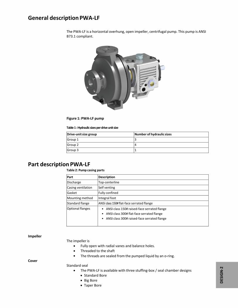
General description PWA‐LF The PWA‐LF is a horizontal overhung, open impeller, centrifugal pump. This pump is ANSI B73.1 compliant.
Figure 1: PWA‐LF pump Table 1 : Hydraulic sizes per drive unit size
Drive‐unit size group Number of hydraulic sizes
Group 1 3
Group 2 4
Group 3 1
Part description PWA‐LF Table 2: Pump casing parts
Part Description
Discharge Top‐centerline
Casing ventilation Self venting
Gasket Fully confined
Mounting method Integral foot
Standard flange ANSI class 150# flat‐face serrated flange
Optional flanges • ANSI class 150# raised‐face serrated flange
• ANSI class 300# flat‐face serrated flange
• ANSI class 300# raised‐face serrated flange
Impeller The impeller is
Fully open with radial vanes and balance holes. Threaded to the shaft The threads are sealed from the pumped liquid by an o‐ring.
Cover Standard seal
The PWA‐LF is available with three stuffing‐box / seal chamber designs Standard Bore Big Bore Taper Bore

DESIGN‐3
Table 3: Power end main parts
Part Description
Frame adapter The carbon steel frame adapter has
• A machined rabbet fitted to the seal chamber/ stuffing box cover
Power end • Flinger oil lubrication is standard.
• No machining is required to convert from oil to grease or oil‐mist
lubrication. Regreaseable bearings and oil‐mist lubrication are optional.
• The oil level is checked through a sight glass located on both sides of
the power end.
• The power end is sealed with labyrinth seals.
• The power end is made in the following sizes:
• Group 1
• Group 2
• Group 3
Shaft The shaft is available with or without a sleeve.
Bearings The Non‐Drive End (INBOARD) bearing
• Carries only radial loads.
• Is free to float axially in the frame.
• Is a single‐row deep‐groove ball bearing
The Drive End (OUTBOARD) bearing
• Is shouldered and locked to the shaft and housing to enable it to carry radial and thrust loads.
• Is a double‐row angular‐contact bearing, except for the Group 3 which uses a pair of single‐row angular‐contact ball bearings mounted back‐to‐back.
Figure 2: PWA‐LF Power End Cross Sectional Important information for ordering Every pump has nameplates that provide information about the pump. The nameplates are located on the casing and the bearing frame. When you order spare parts, identify this pump information:
Model Size Serial number Item numbers of the required parts
Refer to the nameplate on the pump casing for most of the information. See Parts List for item numbers.

DESIGN‐4
Nameplate types Table 4: Nameplate Description Nameplate Description
Pump casing Provides information about the hydraulic characteristics of the pump. Discharge x Suction x Nominal Maximum Impeller diameter (in inches). (Example: 2x3x8)
Bearing frame Provides information about the bearings, lubrication and power end specific serial number.
ATEX If applicable, your pump unit might have an ATEX nameplate affixed to the pump, the baseplate, or the discharge head. The nameplate provides information about the ATEX specifications of this pump.
Figure 3: Nameplate on the pump casing using English units
Table 5: Definition of nameplate on the pump casing english units
Nameplate field Definition
IMPLR. DIA. Trimmed Impeller diameter, in inches
MAX. DIA. Maximum impeller diameter, in inches
GPM Rated pump flow, in gallons per minute
FT HD Rated pump head, in feet
RPM Rated pump speed, revolutions per minute
MOD. Pump model
SIZE Size of the pump
STD. NO. ANSI standard designation
MAT L. CONST. Material of which the pump is constructed
SER. NO. Serial number of the pump
MAX DSGN PSI @ 100ºF
Maximum pressure at 100ºF according to the pump design

DESIGN‐5
Figure 4: Nameplate on the pump casing using metric units
Table 6: Definition of nameplate on the pump casing in metric units
Nameplate field Definition
IMPLR. DIA. Impeller diameter, in mm
MAX. DIA. Maximum impeller diameter, in mm
M3/HR Rated pump flow, in cubic meters per hour
M HD Rated pump head, in meters
RPM Rated pump speed, in revolutions per minute
MOD. Pump model
SIZE Size of the pump
STD. NO. ANSI standard designation
MAT L. CONST Material of which the pump is constructed
SER. NO. Serial number of the pump
MAX. DSGN Pressure kPag 30°C
Maximum Design Working Pressure @ 30°C
Figure 5: Nameplate on the bearing frame
Table 7: Explanation of the nameplate on the Bearing Frame Assembly
Nameplate field Definition
BRG. O. B. Outboard bearing designation (Drive End)
BRG. I. B. Inboard bearing designation (Non‐Drive End)
S/N Serial number of the Bearing Frame Assembly
LUBE Oil or Grease Type

HANDLE‐1
Transportation and Storage

HANDLE‐2
Inspect the delivery
Inspect the package 1. Inspect the package for damaged or missing items upon delivery.
2. Note any damaged or missing items on the receipt and freight bill.
3. File a claim with the shipping company immediately if anything is out of order.
NOTE: Contact your local PW‐IND sales office if any items are missing or for replacement components.
Inspect the pump unit 1. Inspect the product to determine if any parts have been damaged or are missing. 2. Note and report any evidence of damaged paint to your PW‐IND representative. This might be evidence of impact damage during shipment that could result in reduced product performance.
Transportation guidelines
Pump handling
WARNING:
Make sure that the unit cannot roll or fall over and injure people or damage property.
PW‐IND pumps contain sensitive parts that can be damaged if dropped or subjected to impact. Handle the equipment with care and do not attempt to install or operate a pump unit that is damaged.
Lifting methods
WARNING:
All lifting must be done in compliance with all applicable regulations/standards.
Assembled units and their components are heavy. Failure to properly lift and support this equipment can result in serious physical injury and/or equipment damage. Lift equipment only at the specifically identified lifting points.
Crush hazard. The unit and the components can be heavy. Use proper lifting methods and wear steel‐toed shoes at all times.
Do not lift any pump or motor by attaching lifting equipment to shaft ends. Table 1: Lifting Methods
Pump type Liftingmethod
A bare pump without lifting handles
Use a suitable sling attached properly to solid points like the casing, the flanges, or the frames.
A base‐mounted pump Use slings under the pump casing and the drive unit, or under the base rails.
Mounted on a Polymer Composite Baseplate
See separate information regarding the Polymer Composite Baseplate.

HANDLE‐3
Examples
Figure 1: Example of Proper Lifting – Bare Pump
NOTICE: Do not use this lifting method to lift a Polymer Composite Baseplate with the pump and motor mounted. Doing so may result in equipment damage.
Figure 2: Example of Proper Lifting – Base Mounted Pump

HANDLE‐4
NOTICE:
Ensure that lifting strap is located at motor feet‐frame, and clear of motor fan shroud prior to lifting.
NOTICE:
Do not use this lifting method to lift a Polymer Composite Baseplate with the pump and motor mounted. Doing so may result in equipment damage. Figure 3: Example of Proper Lifting – Base Mounted Pump with Motor Figure 4: Example of Proper Lifting – Fabricated Base Mounted Pump with Motor

HANDLE‐5
Figure 5: Example of Proper Lifting – Pump with Frame Adapter
Storage guidelines
Pump storage requirements Storage requirements depend on the amount of time the pump unit will be stored prior to installation and start up. The normal packaging is designed only to protect the unit during shipping. Table 2: Storage
Length of time in storage Storage requirements
Upon receipt/short‐term (less than six months) • Store in a covered and dry location.
• Store the unit free from dirt and vibration.
Long‐term (more than six months) • Store in a covered and dry location.
• Store the unit free from heat, dirt, and vibration.
• Rotate the shaft by hand several times at least every month ensuring that the shaft is not in the same position each time.
NOTICE:
Risk of damage to the mechanical seal or shaft sleeve on units supplied with
cartridge mechanical seals. Follow seal manufacture’s recommendations for
long term storage.
Treat bearing and machined surfaces so that they are well preserved. Refer to
motor and coupling manufacturers for their long‐term storage procedures.
Long term storage preparation is available as part of initial product purchase or after
your pump has been delivered. Contact your local PW‐IND sales representative.

HANDLE‐6
Frostproofing
Table 3: Situations when the pump is or is not frostproof
Situation Condition
Operating The pump is frostproof.
Not Operating The pump internals might be subject to frost damage. Protect non‐operational units with climate control or an anti‐freeze solution in the casing. NEVER USE AN ANTI‐FREEZE AGENT IN THE PUMP BEARING HOUSING.

INST
ALL
-1
Installation

INST
ALL
-2
Precautions WARNING:
When installing in a potentially explosive environment, make sure that the motor and other electrical equipment are properly rated for the area of classification.
You must ground all electrical equipment. This applies to the pump equipment, the driver, and any monitoring equipment. Test the ground lead to verify that it is connected correctly.
Electrical Connections must be made by certified electricians in compliance with all international, national, state, and local rules.
NOTICE: Supervision by an authorized PWA-IND representative is recommended to ensure proper installation. Failure to do so may result in equipment damage.
Pump location guidelines Table 1: Guidelines for locations
Guideline Explanation/comment
Keep the pump as close to the liquid source as possible.
This minimizes friction loss and keeps the suction piping as short as possible.
Make sure that the space around the pump is sufficient.
This facilitates ventilation, inspection, maintenance, and service.
If you require lifting equipment such as a hoist or tackle, make sure that there is enough space above the pump.
This makes it easier to properly use the lifting equipment and safely remove and relocate the components to a safe location.
Take into consideration the occurrence of unwanted noise and vibration.
The best pump location for noise and vibration absorption is on a concrete floor.
Foundation requirements Requirements
The foundation must form a permanent, rigid support for the unit. The location and size of the foundation fasteners should be in
accordance with those shown on the construction drawing provided with the pump data package.
The foundation must weigh between three and five times the weight of the entire pump package.
Ensure foundation is level and free of discontinuity to prevent distortion when foundation bolts are tightened.
1. Baseplate 2. Shims or wedges 3. Foundation 4. Sleeve
5. Form 6. Bolt
Figure 1: Sleeve-type bolts
INST
ALL
-3
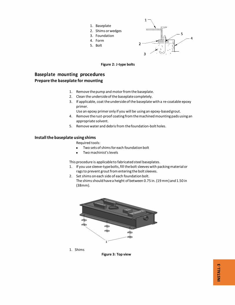
1. Baseplate
2. Shims or wedges 3. Foundation 4. Form 5. Bolt
Figure 2: J-type bolts
Baseplate mounting procedures Prepare the baseplate for mounting 1. Remove the pump and motor from the baseplate. 2. Clean the underside of the baseplate completely. 3. If applicable, coat the underside of the baseplate with a re-coatable epoxy primer. Use an epoxy primer only if you will be using an epoxy-based grout.
4. Remove the rust-proof coating from the machined mounting pads using an appropriate solvent. 5. Remove water and debris from the foundation-bolt holes. Install the baseplate using shims Required tools:
Two sets of shims for each foundation bolt Two machinist's levels
This procedure is applicable to fabricated steel baseplates. 1. If you use sleeve-type bolts, fill the bolt sleeves with packing material or rags to prevent grout from entering the bolt sleeves. 2. Set shims on each side of each foundation bolt. The shims should have a height of between 0.75 in. (19 mm) and 1.50 in (38mm).
1. Shims
Figure 3: Top view

INST
ALL
-4
1. Shims
Figure 4: Side view
3. Lower the baseplate carefully onto the foundation bolts. 4. Set the machinist's levels across the mounting pads of the driver and the mounting pads of the pump. NOTICE: Remove all dirt from the mounting pads in order to make sure that you achieve the correct level indication. 5. Level the baseplate both lengthwise and across by adding or removing shims.
The correct level measurement is a maximum of 0.005 in./ft (400 micrometers/m).
6. Hand-tighten the foundation bolts.
Install the baseplate using jackscrews
Tools required:
Anti-seize compound
Jackscrews
Bar stock
Two machinist's levels This procedure is applicable to the Fabricated Steel PLUS baseplate and the Polymer Composite Baseplate 1. Apply an anti-seize compound on the jackscrews. The compound makes it easier to remove the screws after grouting.
2. Lower the baseplate carefully onto the foundation bolts and perform these steps:
a) Cut plates from bar stock and chamfer the edges of the plates in order to reduce stress concentrations. b) Put the plates between the jackscrews and the foundation surface.
c) Use the jackscrews to raise the baseplate above the foundation. For grouted installations, make sure that the distance between the baseplate and the foundation surface is between 0.75 in. (19 mm) and 1.50 in. (38 mm).
For non-grouted installations, the baseplate should be raised the minimum distance required for leveling.

INST
ALL
-5
1. Jackscrew
2. Baseplate 3. Foundation 4. Plate
Figure 5: Jackscrew bolts
3. Level the driver mounting pads:
The correct level measurement is a maximum of 0.005 in./ft (400 micrometers/m).
NOTICE:
Remove all dirt from the mounting pads in order to make sure that you achieve the correct level indication.
The correct level measurement is a maximum of 0.005 in./ft (400
micrometers/m). a) Put one machinist's level lengthwise on one of the two pads. b) Put the other machinist's level across the ends of the two pads. c) Level the pads by adjusting the four jackscrews in the corners.
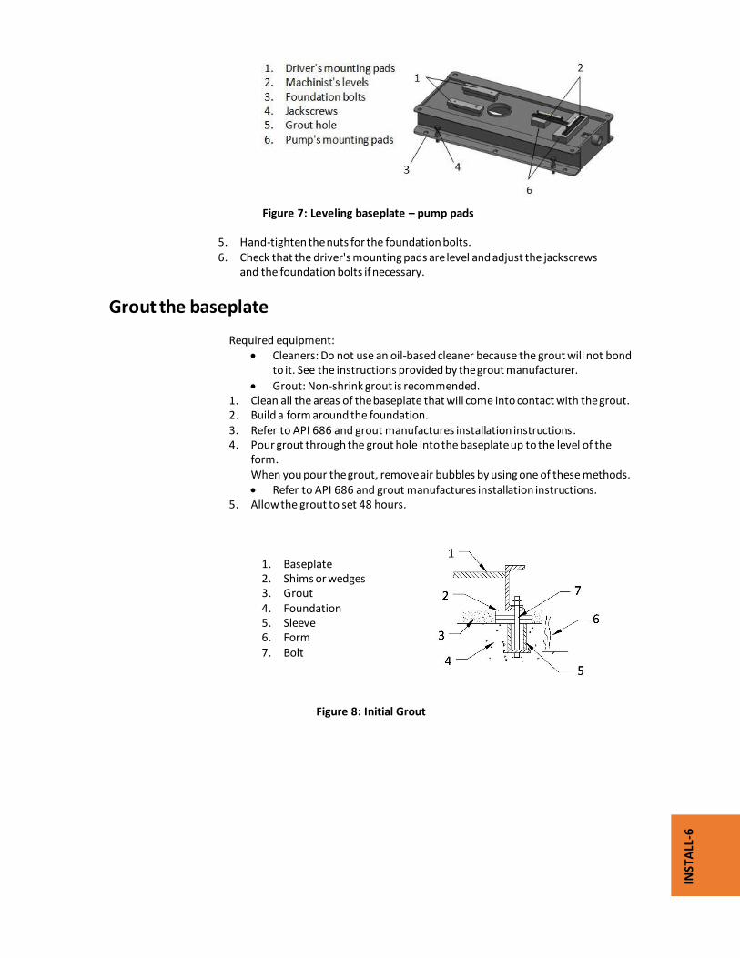
Figure 6: Leveling baseplate – motor pads
4. Level the pump mounting pads. The correct level measurement is a maximum of 0.005 in./ft (400
micrometers/m). a) Put one machinist's level lengthwise on one of the two pads. b) Put the other level across the center of the two pads. c) Level the pads by adjusting the four jackscrews in the corners.
Make sure that the machinist's level readings are as close to zero as possible, both lengthwise and across.
6
INST
ALL
-6
Figure 7: Leveling baseplate – pump pads 5. Hand-tighten the nuts for the foundation bolts. 6. Check that the driver's mounting pads are level and adjust the jackscrews and the foundation bolts if necessary.
Grout the baseplate Required equipment:
Cleaners: Do not use an oil-based cleaner because the grout will not bond to it. See the instructions provided by the grout manufacturer.
Grout: Non-shrink grout is recommended. 1. Clean all the areas of the baseplate that will come into contact with the grout. 2. Build a form around the foundation. 3. Refer to API 686 and grout manufactures installation instructions. 4. Pour grout through the grout hole into the baseplate up to the level of the
form. When you pour the grout, remove air bubbles by using one of these methods.
Refer to API 686 and grout manufactures installation instructions. 5. Allow the grout to set 48 hours. 1. Baseplate 2. Shims or wedges 3. Grout 4. Foundation 5. Sleeve 6. Form 7. Bolt
Figure 8: Initial Grout

INST
ALL
-7
6. Fill the remainder of the baseplate with grout, and allow the grout to set for at least 48 hours. 1. Baseplate 2. Grout 3. Foundation 4. Form 5. Bolt
Figure 9: Final Grout
7. Refer to the grout manufacturer’s instructions for tightening the foundation
bolts. Over tightening the foundation bolts before proper cure can damage the grout and distort the baseplate.
8. Ping test baseplate for voids. Where voids are located, drill and tap an air release hole and an opposing hole. Tap and thread opposing hole with zirc fitting and gently fill void with grout.
WARNING:
Always re-confirm baseplate level AFTER GROUTING per the procedure in this section prior to re-installing the pump and motor.
Install the pump, driver, and coupling
1. Mount and fasten the pump on the baseplate. Use appropriate bolts. 2. Mount the driver on the baseplate. Use appropriate bolts and hand tighten. 3. Install the coupling. (See the installation instructions from the coupling manufacturer.)
Pump-to-driver alignment
Precautions WARNING:
Follow shaft alignment procedures in order to prevent catastrophic failure of drive components or unintended contact of rotating parts. Follow the coupling installation and operation procedures from the coupling manufacturer.
Always disconnect and lock out power all potential energy sources (electrical, hydraulic, pneumatic, etc.) before you perform any installation maintenance tasks.
Failure to do so will result in serious physical injury. Refer to driver/coupling/gear manufacturers installation and operation manuals (IOM) for specific instructions and recommendations.
NOTICE:
Each PW-IND complete pump package is factory aligned to ensure assembly integrity. It is the user’s responsibility to perform a final alignment before start up.

INST
ALL
-8
Alignment checks
When to perform alignment checks Additional alignment checks are REQUIRED when:
The process temperature changes. The piping changes. The pump has been serviced.
Types of alignment checks
Table 2: Alignment checks
Type of alignment When to perform
Initial alignment (cold alignment) check
Prior to operation when the pump and the driver are at ambient temperature.
Final alignment (hot alignment) check
After operation when the pump and the driver are at operating temperature.
Initial alignment (cold alignment)
Table 3: Initial alignment - cold
When Why
Before you grout the baseplate This ensures that alignment can be accomplished.
After you grout the baseplate This ensures that no changes have occurred during the grouting process.
After you connect the piping This ensures that pipe strains have not altered the alignment. If changes have occurred, you must alter the piping to remove pipe strains on the pump flanges.
Final alignment (hot alignment) Table 4: Final alignment - hot
When Why
After the first run This ensures correct alignment when both the pump and the driver are at operating temperature.
Periodically This follows the plant operating procedures
Permitted indicator values for alignment checks
NOTICE: The specified permitted reading values are valid only at operating temperature. For cold settings, other values are permitted. You must use the correct tolerances. Failure to do so can result in misalignment and reduced pump reliability.
When dial indicators are used to check the final alignment, the pump and drive unit are correctly aligned when these conditions are true:
The total indicator runout (TIR) is a maximum of 0.002 in. (0.05 mm) parallel offset at operating temperature.
The tolerance of the indicator is 0.0005 in./in. (0.0127 mm/mm) angularity of indicator separation at operating temperature.

INST
ALL
-9
Cold settings for parallel vertical alignment A vertical offset of the pump driver is required during the cold alignment process.
Consult the driver installation manual or your PW-IND representative for the proper vertical offset.
Alignment measurement guidelines Table 5: Measurement guidelines
Guideline Explanation
Rotate the pump coupling half and the driver coupling half together so that the indicator rods have contact with the same points on the driver coupling half.
This prevents incorrect measurement.
Move or shim only the driver in order to make adjustments. Avoid shimming the pump feet.
This prevents strain on the piping installations.
Make sure that the hold-down bolts for the driver feet are tight when you take indicator measurements.
This keeps the driver stationary since movement causes incorrect measurement.
Make sure that the hold-down bolts for the driver feet are loose before you make alignment corrections.
This makes it possible to move the driver when you make alignment corrections.
Check the alignment again after any mechanical adjustments.
This corrects any misalignments that an adjustment may have caused.
Attach the dial indicators for alignment You must have two dial indicators in order to complete this procedure. 1. Attach two dial indicators on the pump coupling half (X): a) Attach one indicator (P) so that the indicator rod comes into contact with the perimeter of the driver coupling half (Y). This indicator is used to measure parallel misalignment. b) Attach the other indicator (A) so that the indicator rod comes into contact with the inner end of the driver coupling half.
P = Parallel Reading
A = Angular Reading
X = Motor Hub
Y = Pump Hub Figure 10: Dial indicator alignment
2. Rotate the pump coupling half (X) in order to check that the indicators are in contact with the driver coupling half (Y) but do not bottom out.
3. Adjust the indicators if necessary.

INST
ALL
-10
Pump-to-driver alignment instructions
Perform angular alignment for a vertical correction 1. Set the angular alignment indicator to zero at the top-center position (12 o’clock) of the driver coupling half (Y). 2. Rotate the indicator to the bottom-center position (6 o’clock). 3. Record the indicator reading.
Table 6: Angular alignment for vertical correction guidelines
When the reading value is... Then...
Negative The coupling halves are farther apart at the bottom than at the top. Perform one of these steps: • Add shims in order to raise
the feet of the driver at the shaft end.
• Remove shims in order to lower the feet of the driver at the other end.
Positive The coupling halves are closer at the bottom than at the top. Perform one of these steps: • Remove shims in order to lower
the feet of the driver at the shaft end.
• Add shims in order to raise the feet of the driver at the other end.
Figure 11: Side view of an incorrect vertical alignment
4. Repeat the previous steps until the permitted reading value is achieved.
Perform angular alignment for a horizontal correction
1. Set the angular alignment indicator (A) to zero on left side of the driver coupling half (Y), 90° from the top-center position (9 o’clock).
2. Rotate the indicator through the top-center position to the right side, 180° from the start position (3 o’clock).
3. Record the indicator reading.

INST
ALL
-11
Table 7: Angular alignment horizontal correction guidelines
When the reading value is... Then...
Negative The coupling halves are farther apart on the right side than the left. Perform one of these steps: • Slide the shaft end of the driver to the left. • Slide the opposite end to the right.
Positive The coupling halves are closer together on the right side than the left. Perform one of these steps: • Slide the shaft end of the driver to the right. • Slide the opposite end to the left.
Figure 12: Top view of an incorrect horizontal alignment
4. Repeat the previous steps until the permitted reading value is achieved.
Perform parallel alignment for a vertical correction
A unit is in parallel alignment when the parallel indicator (P) does not vary by more than 0.002 in. (0.05 mm) as measured at four points 90° apart at the operating temperature.
1. Set the parallel alignment indicator (P) to zero at the top-center position (12 o’clock) of the driver coupling half (Y).
2. Rotate the indicator to the bottom-center position (6 o’clock). 3. Record the indicator reading.
Table 8: Parallel alignment for vertical correction guidelines
When the reading value is... Then...
Negative The pump coupling half (X) is lower than the driver coupling half (Y). Remove shims of a thickness equal to half of the indicator reading value under each driver foot.
Positive The pump coupling half (X) is higher than the driver coupling half (Y). Add shims of a thickness equal to half of the indicator reading value to each driver foot.

INST
ALL
-12
Figure 13: Side view of an correct vertical alignment
Repeat the previous steps until the permitted reading value is achieved.
NOTICE: The specified permitted reading values are only valid at operating temperatures. For cold settings, other values are permitted. You must use the correct alignment tolerance. Failure to do so can result in misalignment and reduced pump reliability.
Perform parallel alignment for a horizontal correction A unit is in parallel alignment when the parallel indicator (P) does not vary by more
than 0.002 in. (0.05 mm) as measured at four points 90° apart at the operating temperature.
1. Set the parallel alignment indicator (P) to zero on the left side of the driver coupling half (Y), 90° from the top-center position (9 o’clock).
2. Rotate the indicator through the top-center position to the right side, 180° from the start position (3 o’clock).
3. Record the indicator reading.
Table 9: Parallel alignment for horizontal correction guidelines
Make sure to slide the driver evenly. Failure to do so can negatively affect horizontal angular correction. Figure 14: Top view of a correct horizontal alignment 4. Repeat the previous steps until the permitted reading value is achieved
When the reading value is... Then...
Negative The driver coupling half (Y) is to the left of the pump coupling half (X).
Positive The driver coupling half (Y) is to the right of the pump coupling half (X).

INST
ALL
-13
NOTICE: The specified permitted reading values are valid only at operating temperature. For cold settings, other values are permitted. You must use the correct alignment tolerances. Failure to do so can result in misalignment and reduced pump reliability.
Perform complete alignment for a vertical correction A unit is in complete alignment when both the angular indicator (A) and the parallel indicator (P) do not vary by more than 0.002 in. (0.05 mm) as measured at four points 90° apart. 1. Set the angular and parallel dial indicators to zero at the top-center position (12 o’clock) of the driver coupling half (Y). 2. Rotate the indicators to the bottom-center position (6 o’clock). 3. Record the indicator readings. 4. Make corrections according to the separate instructions for angular and parallel alignment until you obtain the permitted reading values.
Perform complete alignment for a horizontal correction A unit is in complete alignment when both the angular indicator (A) and the parallel indicator (P) do not vary by more than 0.002 in. (0.05 mm) as measured at four points 90° apart. 1. Set the angular and parallel dial indicators to zero at the left side of the driver coupling half (Y), 90° from the top-center position (9 o’clock). 2. Rotate the indicators through the top-center position to the right side, 180° from the start position (3 o’clock). 3. Record the indicator readings. 4. Make corrections according to the separate instructions for angular and parallel alignment until you obtain the permitted reading values.
Piping checklists
General piping checklist Precautions CAUTION:
Never draw piping into place by using force at the flanged connections of the
pump. This can impose dangerous strains on the unit and cause misalignment between the pump and driver. Pipe strain adversely affects the operation of the pump, which results in physical injury and damage to the equipment.
Vary the capacity with the regulating valve in the discharge line. Never throttle the
flow from the suction side. This action can result in decreased performance,
unexpected heat generation, and equipment damage.

INST
ALL
-14
Piping guidelines Guidelines for piping are given in the Hydraulic Institute Standards
Checklist Table 10: Piping guidelines
Check Explanation/comment Checked
Check that all piping is supported independently of, and lined up naturally with, the pump flange.
This helps to prevent: • Strain on the pump • Misalignment between the pump and the drive unit • Wear on the pump bearings and the coupling • Wear on the pump bearings, seal, and shafting
Keep the piping as short as possible.
This helps to minimize friction losses.
Check that only necessary fittings are used.
This helps to minimize friction losses.
Do not connect the piping to the pump until: • The grout for the baseplate or
sub-base becomes hard. • The hold-down bolts for the
pump and the driver are tightened.
—
Make sure that all the piping joints and fittings are airtight.
This prevents air from entering the piping system or leaks that occur during operation.
If the pump handles corrosive fluids, make sure that the piping allows you to flush out the liquid before you remove the pump.
If the pump handles liquids at elevated temperatures, make sure that the expansion loops and joints are properly installed.
This helps to prevent misalignment due to linear expansion of the piping.
Pump flange and piping flange face alignment and separation.
The pump and piping flange faces shall be parallel to a min. of .001 in./in. ( 10 micrometers/cm) of outer flange diameter.
Flange face separation, including single gasket spacing, shall be 1/16” ( 1.5 mm).

INST
ALL
-15
Example: Installation for expansion
Correct Incorrect
Fastening
WARNING:
Only use fasteners of the proper size and material. Replace all corroded fasteners. Make sure that all fasteners are properly tightened and that there are no missing
fasteners.
Suction piping checklist
Performance curve reference
Net positive suction head available (NPSHA) must always exceed NPSH required
(NPSHR or NPSH3) as shown on the published performance curve of the pump.
Suction-piping checks Table 11: Suction piping guidelines
Check Explanation/comment Checked
Check that the distance between the inlet flange of the pump and the closest bend is at least five pipe diameters.
This minimizes the risk of cavitation in the suction inlet of the pump due to turbulence. See the Example sections for il- lustrations.
Check that component or pipe diameter change in general do not have sharp bends.
See the Example sections for il- lustrations.

INST
ALL
-16
Liquid source below the pump Table 12: Suction piping guidelines – Liquid source below pump
Check Explanation/comment Checked
Make sure that the suction piping is free from air pockets.
This helps to prevent the occurrence of air and cavitation in the pump inlet.
Check that the suction piping slopes upwards from the liquid source to the pump inlet.
This prevents air from accumulating in the suction piping.
If the pump is not self-priming, check that a device for priming the pump is installed.
Use a foot valve with a diameter that is at least equivalent to the diameter of the suction piping. End user must accommodate for foot valve friction losses in priming & suction calculations.
Liquid source above the pump Table 13: Suction piping guidelines – Liquid source above pump
Check Explanation/comment Checked
Check that an isolation valve is installed in the suction piping at a distance of at least two times the pipe diameter from the suction inlet.
This permits you to close the line during pump inspection and maintenance. Do not use the isolation valve to throttle the pump. Throttling can cause these problems: • Loss of priming • Excessive temperatures • Damage to the pump • Voiding the warranty
Make sure that the suction piping is free from vapor pockets.
This helps to prevent the occurrence of vapors and cavitation in the pump inlet.
Check that the piping is level or slopes downward from the liquid source.
—
Check that the suction piping is one or two sizes larger than the suction inlet of the pump. Install an eccentric reducer be- tween the pump inlet and the suction piping.
The suction piping must never have a smaller diameter than the suction inlet of the pump. See the Example sections for il- lustrations.
Check that the eccentric reducer at the suction flange of the pump has the following properties: • Sloping side down • Horizontal side at the top
See the example illustrations.
When suction strainers or suction bells are used, check that they are at least three times the area of the suction piping.
Suction strainers help to prevent clogging. Mesh holes with a minimum diameter of 1/16 in. (1.6 mm) are recommended.
If more than one pump operates from the same liquid source, check that separate suction-piping lines are used for each pump.
This recommendation helps you to achieve a higher pump performance.
If necessary, make sure that the suction piping includes a drain valve and that it is correctly in- stalled.
—

INST
ALL
-17
Make sure that no part of the suction piping extends below the suction flange of the pump.
—
Make sure that the suction piping is adequately submerged below the surface of the liquid source.
This prevents air from entering the pump through a suction vortex.
Example: Elbow close to the pump suction inlet
Correct Incorrect
The correct distance between the inlet flange of the pump and the closest elbow must be at least five pipe diameters
1).Sufficient distance to prevent disturbances that can result in cavitation. 2).Eccentric reducer with level top.
1
2

INST
ALL
-18
Example: Suction piping below pump
Correct Incorrect
`
Discharge piping checklist Table 14: Discharge piping guidelines
Check Explanation/comment Checked
Check that an isolation valve is installed in the discharge line.
The isolation valve is required for: • Priming • Regulation of flow • Inspection and maintenance of the pump See Example: Discharge piping equipment for illustrations.
Check that a check valve is installed in the discharge line, between the isolation valve and the pump discharge outlet.
The location between the isolation valve and the pump allows inspection of the check valve. The check valve prevents damage to the pump and seal due to back flow through the pump when the drive unit is shut off. See Example: Discharge piping equipment for illustrations.
If increasers are used, check that they are installed between the pump and the check valve.
See Example: Discharge piping equipment for illustrations.
If quick-closing valves are installed in the system, check that cushioning devices are used.
This protects the pump from surges and water hammer.
1). Suction piping sloping upwards from liquid source. 2). Long-radius elbow.
3). Eccentric reducer with a level top
1
2
3
INST
ALL
-19
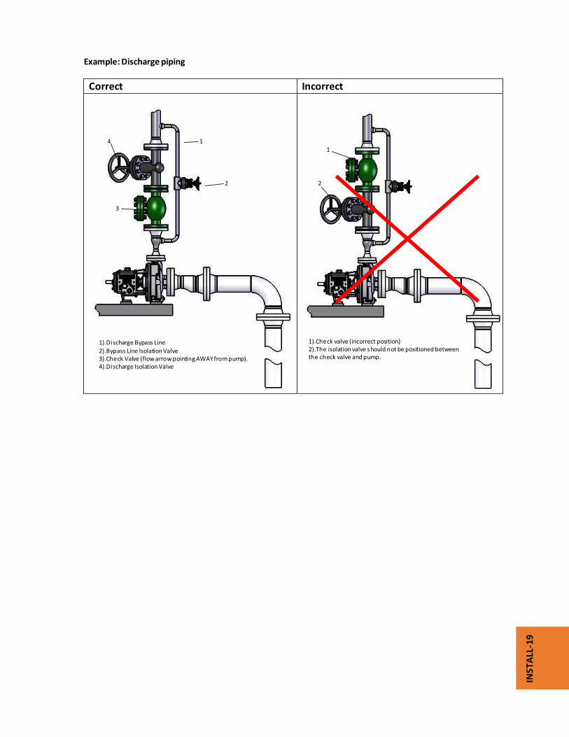
Example: Discharge piping
Correct Incorrect
1).Discharge Bypass Line
2).Bypass Line Isolation Valve 3).Check Valve (flow arrow pointing AWAY from pump). 4).Discharge Isolation Valve
1
2
4
3
1
2
1).Check valve (incorrect position) 2).The isolation valve should not be positioned between the check valve and pump.

STARTU
P‐1
Commissioning, Startup, Operation, and
Shutdown

STARTU
P‐2
Preparation for startup
WARNING:
Failure to follow these precautions before you start‐up the pump could lead to serious injury and equipment failure.
Do not operate the pump below the minimum rated flow or with the suction or discharge valves closed.
Avoid death or serious injury. Leaking fluid can cause fire and/or burns. Operating the pump above maximum rated flow shown on the pump curve leading to an increase in horsepower and vibration along with mechanical seal and/or shaft failure.
Never operate the pump without the coupling guard correctly installed.
Always disconnect and lock out all potential energy sources (electrical, hydraulic, pneumatic, etc) before you perform any installation or maintenance tasks. Failure to disconnect and lock out driver power could result in serious physical injury.
Operating the pump in reverse rotation will result in the contact of metal parts, heat generation, and breach of containment.
Precautions NOTICE: Verify the driver settings before you start any pump.
Make sure that the pump casing warm‐up rate does not exceed 5°F (2.8°C) per minute.
Risk of damage to the mechanical seal or shaft sleeve on units supplied with cartridge mechanical seals. Prior to startup, make sure to tighten the set screws in the seal locking collar and remove the centering clips.
You must follow these precautions before you start the pump:
Flush and clean the system thoroughly prior to start‐up to remove dirt or
debris in the pipe system. If temperatures of the pumped fluid will exceed 200°F (93°C), then warm up
the pump prior to operation. Circulate a small amount of fluid through the
pump until the casing temperature is within 50°F (10°C) of the process fluid
temperature. Soak for (2) hours at process fluid temperature. Remove the coupling guard
1. Remove the nut, bolt, and washers from the slotted hole in the center of the coupling guard.
2. Slide the driver half of the coupling guard toward the pump.
Figure 1: Guard removal – slide driver half

STARTU
P‐3
3. Remove the nut, bolt, and washers from the driver half of the coupling guard.
4. Remove the driver‐side end plate.
Figure 2: Guard removal – driver side end plate 5. Remove the driver half of the coupling guard: a) Slightly spread the bottom apart. b) Lift upwards.
Figure 3: Guard removal –driver half
Driver‐side end plate
Driver
STARTU
P‐4
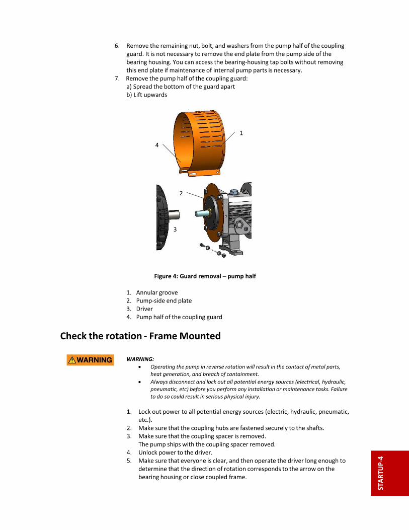
6. Remove the remaining nut, bolt, and washers from the pump half of the coupling guard. It is not necessary to remove the end plate from the pump side of the bearing housing. You can access the bearing‐housing tap bolts without removing this end plate if maintenance of internal pump parts is necessary. 7. Remove the pump half of the coupling guard: a) Spread the bottom of the guard apart b) Lift upwards
Figure 4: Guard removal – pump half 1. Annular groove 2. Pump‐side end plate 3. Driver 4. Pump half of the coupling guard
Check the rotation ‐ Frame Mounted
WARNING:
Operating the pump in reverse rotation will result in the contact of metal parts, heat generation, and breach of containment.
Always disconnect and lock out all potential energy sources (electrical, hydraulic, pneumatic, etc) before you perform any installation or maintenance tasks. Failure to do so could result in serious physical injury.
1. Lock out power to all potential energy sources (electric, hydraulic, pneumatic, etc.). 2. Make sure that the coupling hubs are fastened securely to the shafts. 3. Make sure that the coupling spacer is removed. The pump ships with the coupling spacer removed. 4. Unlock power to the driver. 5. Make sure that everyone is clear, and then operate the driver long enough to determine that the direction of rotation corresponds to the arrow on the bearing housing or close coupled frame.
1
3
2
4

STARTU
P‐5
Impeller‐clearance check
The impeller‐clearance check ensures the following:
The pump turns freely.
The pump operates at optimal efficiency for long equipment life.
Impeller clearances (PWA‐LF)
WARNING: For pumpage temperatures greater than 200°F (93°C), you must increase the cold (ambient) setting according to this table. Doing so prevents the impeller from contacting the casing due to differential expansion from the higher operating temperatures. Failure to do so may result in equipment damage.
NOTICE: Do not set the maximum impeller setting to more than 0.005 in. (0.13 mm) greater than the values in this table. Doing so may result in a significant decrease in performance. Table 1: Impeller clearances
Service temperature Group 1, 2, 3
in. (mm)
‐20 to 200°F (‐29 to93°C) 0.015 (0.38)
Up to 250°F (121°C) 0.016 (0.41)
Up to 300°F (149°C) 0.017 (0.43)
Up to 350°F (177°C) 0.019 (0.48)
Up to 400°F (204°C) 0.020 (0.50)
Up to 450°F (232°C) 0.021 (0.53)
Up to 500°F (260°C) 0.022 (0.56)
Up to 550°F (288°C) 0.023 (0.58)
Up to 600°F (316°C) 0.024 (0.61)
Up to 650°F (343°C) 0.026 (0.66)
Up to 700°F (371°C) 0.027 (0.69)
Impeller‐clearance setting Importance of a proper impeller clearance
WARNING:
The impeller clearance setting procedure must be followed. Improperly setting the clearance or not following any of the proper procedures can result in equipment damage.
If you use a cartridge mechanical seal, you must install the centering clips and loosen the set screws before you set the impeller clearance. Failure to do so could result in mechanical seal damage.
Impeller clearance methods
You can set the impeller clearance with either of these methods.
Dial indicator method
Feeler gauge method
STARTU
P‐6
228
Set the impeller clearance ‐ dial indicator method WARNING: Always disconnect and lock out all potential energy sources ( electric, hydraulic, pneumatic, etc) before you perform any installation or maintenance tasks. Failure to do so will result in serious physical injury.
1. Remove the coupling guard.
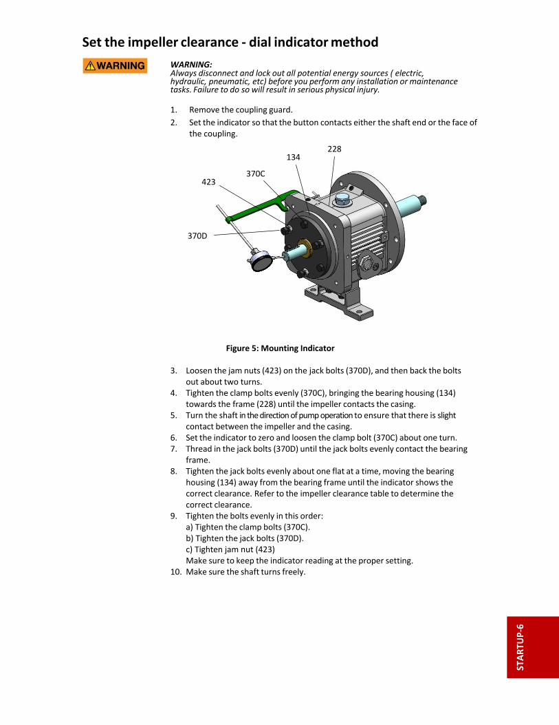
2. Set the indicator so that the button contacts either the shaft end or the face of the coupling.
Figure 5: Mounting Indicator 3. Loosen the jam nuts (423) on the jack bolts (370D), and then back the bolts
out about two turns. 4. Tighten the clamp bolts evenly (370C), bringing the bearing housing (134)
towards the frame (228) until the impeller contacts the casing. 5. Turn the shaft in the direction of pump operation to ensure that there is slight
contact between the impeller and the casing. 6. Set the indicator to zero and loosen the clamp bolt (370C) about one turn. 7. Thread in the jack bolts (370D) until the jack bolts evenly contact the bearing
frame. 8. Tighten the jack bolts evenly about one flat at a time, moving the bearing
housing (134) away from the bearing frame until the indicator shows the correct clearance. Refer to the impeller clearance table to determine the correct clearance.
9. Tighten the bolts evenly in this order: a) Tighten the clamp bolts (370C). b) Tighten the jack bolts (370D). c) Tighten jam nut (423) Make sure to keep the indicator reading at the proper setting. 10. Make sure the shaft turns freely.
370D
423 370C
134

STARTU
P‐7
Set the impeller clearance ‐ feeler gauge method WARNING: Always disconnect and lock out all potential energy sources (electric, hydraulic, pneumatic, etc) before you perform any installation or maintenance tasks. Failure
to do so will result in serious physical injury.
Refer to driver/coupling/gear manufacturers installation and operation manuals (IOM) for specific instructions and recommendations.
1. Remove the coupling guard. 2. Loosen the jam nuts (423B) on the jack bolts (370D), and then back the bolts out about two turns.
Figure 6: Setting Impeller Clearance 3. Evenly tighten the clamp bolts (370C), bringing the bearing housing (134)
towards the frame (228) until the impeller contacts the casing. 4. Turn the shaft in direction of rotation to ensure that there is slight contact
between the impeller and the casing. 5. Use a feeler gauge to set the gap between the three clamp bolts (370C)
and the bearing housing (134) to the correct impeller clearance. Refer to the impeller clearance table to determine the correct clearance. 6. Use the three jack bolts (370D) to evenly move the bearing housing (134)
until it contacts the clamp bolts (370C). 7. Evenly tighten the jam nuts (423B). 8. Make sure the shaft turns freely.
Couple the pump and driver
WARNING: Always disconnect and lock out power to all potential energy sources (electric, hydraulic, pneumatic, etc.) before you perform any installation maintenance tasks. Failure to do so will result in serious physical injury.

STARTU
P‐8
Install the coupling guard WARNING:
Never operate a pump without a properly installed coupling guard. Personal injury will occur if you run the pump without a coupling guard.
Refer to driver/coupling/gear manufacturers IOM for specific instructions and recommendations.
Always disconnect and lock out power to all potential energy sources (electric, hydraulic, pneumatic, etc.) before you perform any installation or maintenance tasks. Failure to disconnect and lock out driver power will result in serious physical injury.
Figure 7: Required guard parts 1. End plate, drive end 2. End plate, pump end 3. Guard half, 2 required 4. 3/8‐16 nut, 3 required 5. 3/8 in. washer, 6 required 6. 3/8‐16 x 2 in. hex head bolt, 3 required 1. Follow appropriate lock out/tag out procedures: De‐energize the motor,
place the motor in a locked‐out position, and place a caution tag at the starter that indicates the disconnect.
2. Put the pump‐side end plate in place. If the pump‐side end plate is already in place, make any necessary coupling
adjustments and then proceed to the next step.
Table 2: Group – Guard Installation guidelines
Pump size Guideline
Group 1, 2, 3 Align the pump‐side end plate to the bearing frame. You do not need to adjust the impeller.

STARTU
P‐9
3. Put the pump‐half of the coupling guard in place: a) Slightly spread the bottom apart. b) Place the coupling guard half over the pump‐side end plate.
Figure 8: Guard install – slide pump half 1. Annular groove 2. Pump‐side end plate 3. Driver
4. Pump half of the coupling guard The annular groove in the coupling guard half must fit around the end plate.
4. Use a bolt, a nut, and two washers to secure the coupling guard half to the end
plate. Tighten securely.
5. Put the driver half of the coupling guard in place. a) Slightly spread the bottom apart. b) Place the driver half of the coupling guard over the pump half of the coupling guard. The annular groove in the coupling guard half must face the motor.
1
2
3
4
STARTU
P‐10
Figure 9: Guard install – slide motor half
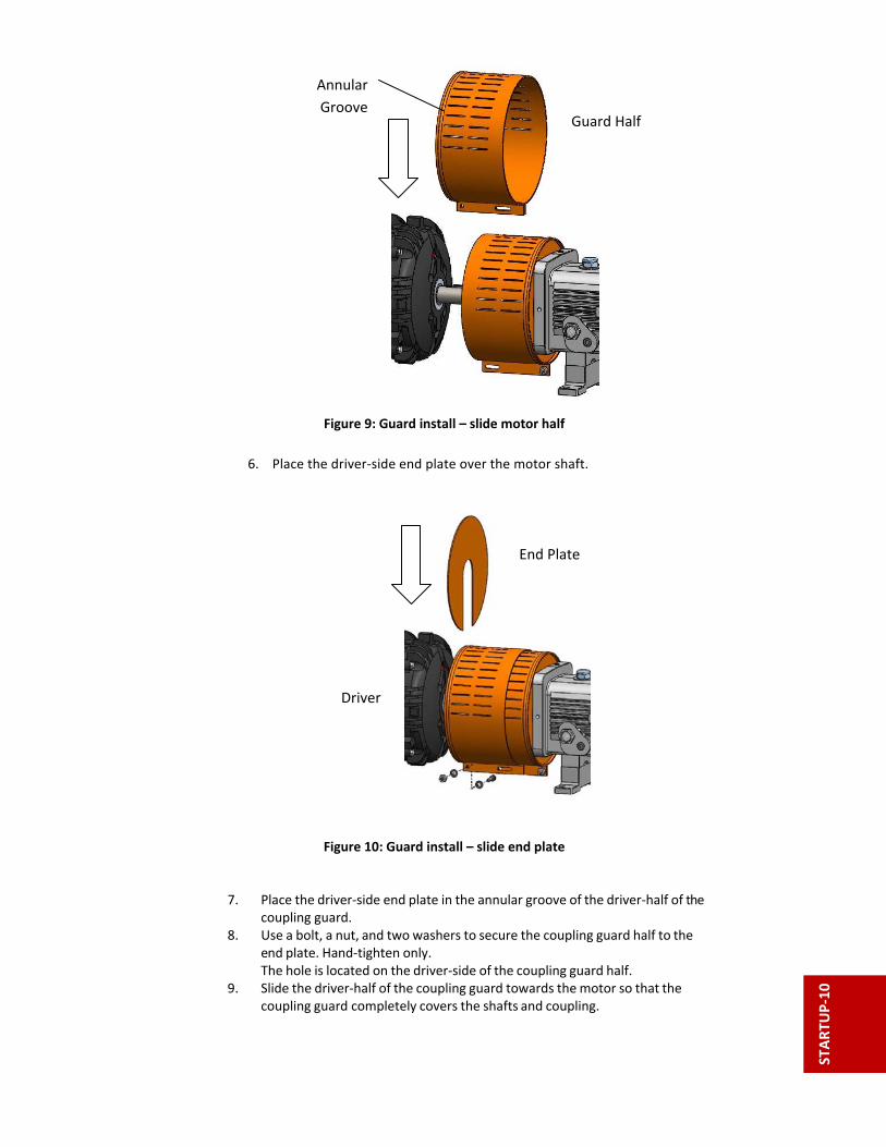
6. Place the driver‐side end plate over the motor shaft.
Figure 10: Guard install – slide end plate 7. Place the driver‐side end plate in the annular groove of the driver‐half of the coupling guard. 8. Use a bolt, a nut, and two washers to secure the coupling guard half to the end plate. Hand‐tighten only. The hole is located on the driver‐side of the coupling guard half. 9. Slide the driver‐half of the coupling guard towards the motor so that the coupling guard completely covers the shafts and coupling.
End Plate
Driver
Guard Half
Annular
Groove
STARTU
P‐11
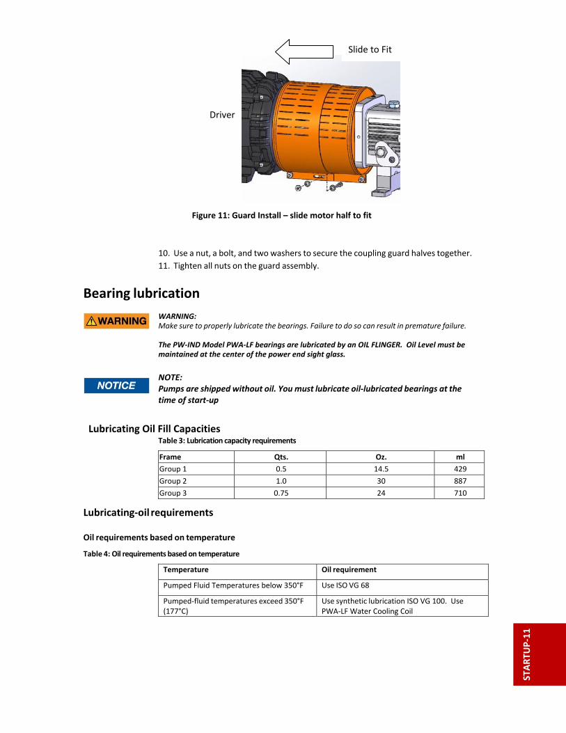
Figure 11: Guard Install – slide motor half to fit
10. Use a nut, a bolt, and two washers to secure the coupling guard halves together.
11. Tighten all nuts on the guard assembly.
Bearing lubrication
WARNING: Make sure to properly lubricate the bearings. Failure to do so can result in premature failure. The PW‐IND Model PWA‐LF bearings are lubricated by an OIL FLINGER. Oil Level must be maintained at the center of the power end sight glass.
NOTE: Pumps are shipped without oil. You must lubricate oil‐lubricated bearings at the
time of start‐up
Lubricating Oil Fill Capacities Table 3: Lubrication capacity requirements
Frame Qts. Oz. ml
Group 1 0.5 14.5 429
Group 2 1.0 30 887
Group 3 0.75 24 710
Lubricating‐oil requirements Oil requirements based on temperature
Table 4: Oil requirements based on temperature
Temperature Oil requirement
Pumped Fluid Temperatures below 350°F Use ISO VG 68
Pumped‐fluid temperatures exceed 350°F (177°C)
Use synthetic lubrication ISO VG 100. Use PWA‐LF Water Cooling Coil
Driver
Slide to Fit

STARTU
P‐12
Acceptable oil for lubricating bearings
Acceptable lubricants Table 5: Examples of acceptable high quality turbine oils with rust and oxidation inhibitors.
Brand Lubricant type
Chevron GTS Oil 68
Exxon Teresstic EP 68
Mobil DTE 26 300 SSU @ 100°F (38°C)
Philips Mangus Oil 315
Shell Tellus Oil 68
Sunoco Sunvis 968
Royal Purple SYNFILM ISO VG 68 Synthetic Lube
Lubricate the bearings with oil
1. Remove the vent cap . 2. Fill the bearing frame with oil through the vent / filler connection, which is located
on top of the bearing frame. Fill the bearing frame with oil until the oil level reaches the middle of the sight glass (319).
Figure 12: Power End – lube fill
3. Replace the fill plug.
Lubricate the bearings with pure oil mist Oil mist is an optional feature for this pump. To lubricate bearings with pure oil mist, follow the instructions provided by the manufacturer of the oil‐mist generator. The inlet connections are on the top of the bearing frame
STARTU
P‐13
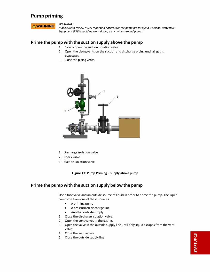
Pump priming WARNING: Make sure to review MSDS regarding hazards for the pump process fluid. Personal Protective Equipment (PPE) should be worn during all activities around pump.
Prime the pump with the suction supply above the pump 1. Slowly open the suction isolation valve. 2. Open the piping vents on the suction and discharge piping until all gas is evacuated. 3. Close the piping vents.
1. Discharge isolation valve
2. Check valve
3. Suction isolation valve
Figure 13: Pump Priming – supply above pump
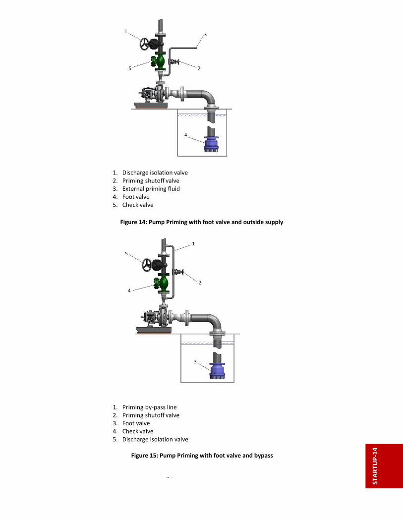
Prime the pump with the suction supply below the pump Use a foot valve and an outside source of liquid in order to prime the pump. The liquid can come from one of these sources:
A priming pump
A pressurized discharge line
Another outside supply 1. Close the discharge isolation valve. 2. Open the vent valves in the casing. 3. Open the valve in the outside supply line until only liquid escapes from the vent valves. 4. Close the vent valves. 5. Close the outside supply line.
STARTU
P‐14
1. Discharge isolation valve 2. Priming shutoff valve 3. External priming fluid 4. Foot valve 5. Check valve
Figure 14: Pump Priming with foot valve and outside supply 1. Priming by‐pass line 2. Priming shutoff valve 3. Foot valve 4. Check valve 5. Discharge isolation valve
Figure 15: Pump Priming with foot valve and bypass

STARTU
P‐15
Start the pump WARNING: Immediately observe the pressure gauges. If discharge pressure is not quickly attained, stop the driver immediately, reprime, and attempt to restart the pump.
CAUTION:
Observe the pump vibration levels, bearing temperature, and excessive noise. If normal levels are exceeded, shut down the pump and resolve the issue.
On pure or purge‐oil mist‐lubricated units, remove the power end vent plug to verify that oil mist flowing properly. Replace the plug.
Ensure that the oil level is correct prior to starting pump.
Before you start the pump, you must perform these tasks:
Open the suction valve.
Open any recirculation or cooling lines. 1. Partially open the discharge valve, depending on system conditions. 2. Start the driver. 3. Slowly open the discharge valve until the pump reaches the desired flow. 4. Immediately check the pressure gauge to ensure that the pump quickly reaches the correct discharge pressure. 5. If the pump fails to reach the correct pressure, perform these steps:
a) Stop the driver. b) Prime the pump again. c) Restart the driver.
6. Monitor the pump while it is operating: a) Check the pump for bearing temperature, excessive vibration, and noise. b) If the pump exceeds normal levels, then shut down the pump
immediately and correct the problem. 7. Repeat steps 5 and 6 until the pump runs properly.
Pump operation precautions General considerations
CAUTION:
Vary the capacity with the regulating valve in the discharge line. Never throttle the flow from the suction side since this can result in decreased performance, unexpected heat generation, and equipment damage.
Do not operate pump past the maximum flow. For maximum flow refer to the pump performance curve.
Do not overload the driver. Driver overload can result in unexpected heat generation and equipment damage. The driver can overload in these circumstance.
The specific gravity of the pumped fluid is greater than expected.
The pumped fluid exceeds the rated flow rate.
Do not operate pump below minimum flow. For minimum flows refer to technical manual and pump performance curve.
Make sure to operate the pump at or near the rated conditions. Failure to do so can result in pump damage from cavitation or recirculation.

STARTU
P‐16
Operation at reduced capacity
WARNING: Never operate any pumping system with a blocked suction and discharge. Operation, even for a brief period under these conditions, can cause confined pumped fluid to overheat, which could result in a explosion. You must take all necessary measures to avoid this condition.
CAUTION:
The pump and system must be free of foreign objects. If pump becomes plugged, shut down and unplug prior to restarting pump.
Avoid excessive vibration levels. Excessive vibration levels can damage the bearings, stuffing box or seal chamber, and the mechanical seal, which can result in decreased performance.
Avoid increased radial load. Failure to do so can cause stress on the shaft and bearings.
Avoid heat build‐up. Failure to do so can cause rotating parts to score or seize.
Avoid cavitation. Failure to do so can cause damage to the internal surfaces of the pump.
Shut down the pump
1. Disengage driver. 2. Allow pump to coast down. 3. Close discharge valve.

MAINT‐1
Maintenance

MAINT‐2
Maintenance schedule
It is recommended that a maintenance plan and schedule is adopted, in line with these Instructions, to include the following: Any auxiliary systems installed must be monitored, if necessary, to ensure they function correctly.
Gland packing must be adjusted correctly to give visible leakage and concentric alignment of the gland follower to prevent excessive temperature of the packing or follower.
Check for any leaks from gaskets and seals. The correct functioning of the shaft seal must be checked regularly.
Check bearing lubricant level, and if the hours run show a lubricant change is required.
Check that the duty condition is in the allowable operating range for the pump.
Check vibration, noise level and surface temperature at the bearings to confirm satisfactory operation.
Check dirt and dust is removed from areas around close clearances, bearing housings and motors.
Check coupling alignment and re‐align if necessary. Our field service technicians can help with preventative maintenance records and provide condition monitoring for temperature and vibration to identify the onset of potential problems. Routine inspection (daily/weekly) The following checks should be made and the appropriate action taken to remedy any deviations:
Check operating behavior. Ensure noise, vibration and bearing temperatures are normal.
Check that there are no abnormal fluid or lubricant leaks (static and dynamic seals) and that any sealant systems (if fitted) are full and operating normally.
Check the level and condition of oil lubricant. On grease lubricated pumps, check running hours since last recharge of grease or complete grease change.
Check any auxiliary systems are functioning correctly.
Refer to the manuals of any associated equipment for routine checks needed. Periodic inspection (six month)
Check foundation bolts for security of attachment and corrosion.
Check pump running records for total operating hours since last service to determine if bearing lubricant requires changing.
Check the coupling for correct alignment and worn driving elements.
Refer to the manuals of any associated equipment for periodic checks needed.
Bearing maintenance These bearing lubrication sections list different temperatures of the pumped fluid.
Table 1: Oil Change Schedule
Type of bearing First lubrication Lubrication intervals
Oil‐lubricated bearings Add oil before you install and start the pump. Change the oil after 400 hours for new bearings.
After the first 400 hours, change the oilevery 2000 operating hours or every three months.
Grease‐lubricated bearings Grease‐lubricated bearings are initially lubricated at the factory.
Re‐grease bearings every 2000 operating hours or every three months.

MAINT‐3
Lubricating‐oil requirements
Lubricating Oil Fill Capacities
Table 2: Required amount of oil for oil‐lubricated bearings.
Frame Qts. Oz. ml
Group 1 0.5 14.5 429
Group 2 1.0 30 887
Group 3 0.75 24 710
Lubricating‐oil requirements Table 3: Oil requirements based on temperature
Temperature Oil requirement
Pumped fluid temperatures below 350⁰ F Use ISO VG 68
Pumped fluid temperatures exceed 350⁰ F Use synthetic lubrication ISO VG 100. Use water cooling coil
Acceptable oil for lubricating bearings
Acceptable lubricants Table 4: Examples of acceptable high quality turbine oils with rust and oxidation inhibitors
Shaft seal maintenance
Mechanical‐seal maintenance
CAUTION: Never operate the pump without liquid supplied to mechanical seal. Lack of seal flush can cause seal damage and catastrophic failure.
Cartridge mechanical seals Cartridge mechanical seals are commonly used. Cartridge seals are preset by the seal manufacturer and require no field settings. Cartridge seals installed by the user require removal of the holding clips and engagement of the set screws prior to operation. If the seal has been installed in the pump by PW‐IND, these clips have already been removed.
Other mechanical seal types
For other types of mechanical seals, refer to the instructions provided by the seal manufacturer for installation and setting.
Before you start the pump
Check the seal and all flush piping.
Brand Lubricant type
Chevron GTS Oil 68
Exxon Teresstic EP 68
Mobil DTE 26 300 SSU @ 100°F (38°C)
Philips Mangus Oil 315
Shell Tellus Oil 68
Sunoco Sunvis 968
Royal Purple SYNFILM ISO VG 68 Synthetic Lube

MAINT‐4
Disassembly
Disassembly precautions
WARNING:
This manual clearly identifies accepted methods for disassembling units. These methods must be followed to ensure safe maintenance of the pump. Trapped liquid can rapidly expand and result in a violent explosion and injury. Never apply heat to impellers or other pump components to aid in their removal unless explicitly stated in this manual.
Always disconnect and lock out power to all potential energy sources (electric, hydraulic, pneumatic, etc.) before you perform any installation or maintenance tasks. Failure to do so will result in serious physical injury.
Refer to driver/coupling/gear manufacturers installation and operation manuals (IOM) for specific instructions and recommendations.
The pump can handle hazardous and toxic fluids. Identify the contents of the pump and observe proper decontamination procedures in order to eliminate the possible exposure to any hazardous or toxic fluids. Wear the proper personal protective equipment. Potential hazards include, but are not limited to, high temperature, flammable, acidic, caustic, explosive, and other risks.
A small amount of liquid will be present in the seal chamber and casing. Take proper precautions to avoid contact with hazardous fluids.
NOTICE:
Avoid injury. Worn pump components can have sharp edges. Wear appropriate gloves while handling these parts.
Tools required Bearing puller Brass drift punch Cleaning agents and solvents Dial indicators Feeler gauges Hex wrenches Hydraulic press Induction heater Leveling blocks and shims Lifting sling Micrometer Rubber mallet Screwdriver Shaft wrench Snap‐ring pliers Torque wrench with sockets Wrenches

MAINT‐5
Drain the pump
CAUTION:
Allow all system and pump components to cool before you handle them to prevent physical injury.
1. Close the isolation valves on the suction and discharge sides of the pump. You must drain the system if no valves are installed. Always disconnect and lock out all potential energy sources (electrical, hydraulic, pneumatic, etc) before you perform any installation or maintenance tasks. 2. Drain the pump. Do not proceed until liquid stops coming out of the drain valve. 3. Leave the drain valve open and remove the drain plug located on the bottom of the pump housing (if supplied). Do not reinstall the plug or close the drain valve until the reassembly is complete. 4. Drain the liquid from the piping and flush the pump if it is necessary. 5. Disconnect all auxiliary piping and tubing. 6. Remove the coupling guard.
Remove the coupling 1. Disconnect the coupling. 2. Remove the coupling guard and motor end plate. 3. Remove the coupling‐guard pump end‐plate.
Remove the back pull‐out assembly
1. Is your bearing frame oil lubricated?
If No: Proceed to step 2
If Yes: 1. Remove the bearing‐frame drain plug (408A) in order to drain oil from the
bearing frame. 2. Replace the plug after the oil is drained. 3. Remove the constant level oiler, if equipped.
Figure 1: Guard removal

MAINT‐6
NOTICE:
Pump oil can be used as part of a predictive / preventive maintenance program.
Save oil in a clean container for further review.
Figure 2: Back pull‐out removal
2. Remove the hold‐down bolts of the bearing frame foot.
3. Remove the casing bolts.
WARNING:
Never use heat to disassemble the pump due to the risk of an explosion from trapped liquid.
4. Tighten the casing jack bolts evenly, using an alternating pattern, in order to remove
the back pull‐out assembly. Use penetrating oil if the adapter to the casing joint is corroded. 5. Remove the back pull‐out assembly from the casing (100). 6. Mark and remove the shims from under the frame foot and save them for
reassembly. Reusing the shims assumes that the same motor frame and frame foot are being installed, and that there has been no change in piping and/or foundation.
7. Remove and discard the casing gasket. Do not ever re‐use the casing gasket. 8. Remove the jackscrews. 9. Clean all gasket surfaces.
Remove the coupling hub 1. Clamp the frame adapter securely to the workbench. 2. Remove the coupling hub.
Mark the shaft for relocation of the coupling hub during reassembly. Reusing the coupling hub assumes that the same motor frame, RPM, and
horsepower are being installed, and that there has been no change in pump operating conditions.

MAINT‐7
Figure 3: Coupling hub removal
Impeller removal Remove the impeller (Group 1, 2, and 3)
WARNING: Never apply heat to remove an impeller. The use of heat may cause an explosion due to trapped liquid, resulting in severe physical injury and property damage.
1. Slide the shaft wrench over the shaft (122) and key. 2. Rotate the impeller (101) clockwise (viewed from the impeller end of the shaft) and raise the wrench off of the work surface. 3. To loosen the impeller, quickly turn it counter‐clockwise (viewed from the impeller end of the shaft) while impacting the wrench handle on the workbench or a solid block.
Figure 4: Impeller removal
4. Repeat step 3 until the impeller is loose. 5. Remove and discard the impeller O‐ring (412A).

MAINT‐8
Do not ever re‐use the impeller O‐ring.
Figure 5: O‐ring for models PWA, PWA‐LF, PWA‐SP
Remove the stuffing box cover (seal chamber) (PWA, PWA‐LF, PWA‐SP) 1. Remove the gland stud nuts (355).
2. Remove the casing cover stud nuts (370H).
3. Remove the casing cover (184).
Figure 6: Seal chamber removal
4. Remove the shaft sleeve (126) if it is used.
The mechanical seal is attached to the sleeve.
NOTICE: Be careful with the stationary portion of the mechanical seal that is either clamped between the backplate and the gland or seated in the stuffing box / seal chamber bore. Failure to do so may result in equipment damage.
5. Remove the rotary portion of the seal from the sleeve by loosening the

MAINT‐9
set screws and sliding it off the sleeve. Refer to the mechanical‐seal instructions for more information.
6. Remove the gland (250), the stationary portion of the seal, and the O‐ring (360Q).
Figure 7: Mechanical seal removal
Remove the frame adapter (Group 2,3) 1. Remove the frame adapter (108).
2. Remove and discard the gasket (360D).
You will install a new gasket during reassembly.
3. Remove the dowel pins (496B) and the bolts (370B).
Figure 8: Adapter removal
469B

MAINT‐10
Remove the inboard labyrinth oil seal Labyrinth oil‐seal O‐rings are part of the PWA‐LF maintenance kits, and they are sold separately.
1. Determine the fit of your labyrinth oil seal.
Table 5: Labyrinth oil‐seal fit
Model Type of fit
Group 1 O‐ring fit into the bearing‐frame adapter
Group 1, 2, 3 O‐ring fit into the frame adapter
2. Remove the O‐rings (497H and 497J) and the seal (333A).
Figure 9: Labyrinth seal removal
Power‐end disassembly General Considerations
To limit the potential for shaft damage, remove ball bearings by applying force to the INNER race.
Regardless of removal technique, ball bearings are NOT re‐usable after they are removed. Always use new bearings.
If bearings are suspected as a cause of failure, retain them for further inspection. Detailed bearing inspection can be a valuable tool in failure analysis.
Avoid removal of Oil Flinger (248) unless it is damaged.
Disassemble the power end (Group 1 & 2) 1. Remove the clamp screws (370C) and back off the jam nuts (423). 2. Tighten the jack screws (370D) evenly to move the bearing housing (134) out of the bearing frame (228). 3. Remove the shaft assembly from the bearing frame (228).

MAINT‐11
Figure 10: Shaft assembly removal
4. Remove the jack screws (370D) with nuts (423).
5. Remove the bearing housing O‐ring (496) and the bearings.
6. Remove the outboard bearing retaining snap ring (361A).
Figure 11: Hardware removal
7. Remove the bearing housing (134) and the shaft (122).
Figure 12: Bearing housing removal
8. Remove the bearing locknut (136) and bearing lock washer (382).
112A
228
248
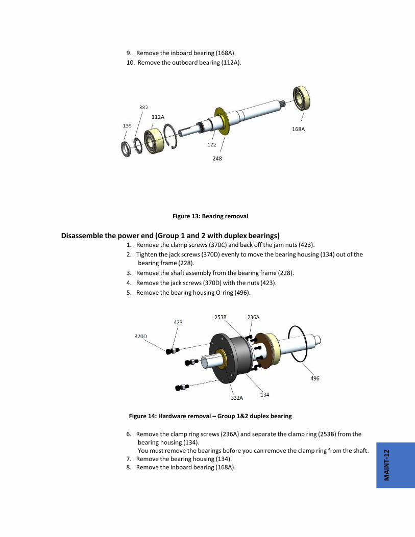
MAINT‐12
9. Remove the inboard bearing (168A).
10. Remove the outboard bearing (112A).
Figure 13: Bearing removal
Disassemble the power end (Group 1 and 2 with duplex bearings)
1. Remove the clamp screws (370C) and back off the jam nuts (423).
2. Tighten the jack screws (370D) evenly to move the bearing housing (134) out of the
bearing frame (228).
3. Remove the shaft assembly from the bearing frame (228).
4. Remove the jack screws (370D) with the nuts (423).
5. Remove the bearing housing O‐ring (496).
Figure 14: Hardware removal – Group 1&2 duplex bearing
6. Remove the clamp ring screws (236A) and separate the clamp ring (253B) from the
bearing housing (134). You must remove the bearings before you can remove the clamp ring from the shaft.
7. Remove the bearing housing (134). 8. Remove the inboard bearing (168A).
168A
112A
248

MAINT‐13
Figure 15: Bearing removal – Group 1 & 2 duplex bearing
9. Remove the bearing locknut (136) and bearing lock washer (382). 10. Remove the outboard bearings (112A) and clamping ring (253B). 11. Remove the outboard labyrinth oil seal (332A) from the bearing housing (134). Remove the O‐rings (497F and 497G) if it is necessary. Labyrinth oil seal O‐rings are part of the PWA‐LF maintenance kits and they are sold separately.
Figure 16: Labyrinth seal removal bearing housing
Disassemble the power end (Group 3) 1. Remove the clamp screws (370C) and back off the jam nuts (423).
2. Evenly tighten the jack screws (370D) to move the bearing housing (134) out of the bearing frame (228).
3. Remove the shaft assembly from the bearing frame (228).
253B

MAINT‐14
Figure 17: Shaft assembly removal
4. Remove the jack screws (370D) with the nuts (423).
5. Remove the clamp‐ring screws (236A) and separate the clamp ring (253B) from the bearing housing (134).
You must remove the bearings before you can remove the clamp ring from the shaft.
6. Remove the bearing housing O‐ring (496) and the inboard bearing (168A).
Figure 18: Hardware removal – Group 3
7. Remove the bearing housing (134).
228

MAINT‐15
Figure 19: Bearing removal – Group 3
8. Remove the inboard bearing (168A)
9. Remove the bearing lock nut (136) and the bearing lock washer (382).
10. Remove the outboard bearings (112A) and the clamp ring (253B).
11. Remove the outboard labyrinth oil seal (332A) from the bearing housing (134).
12. Remove the O‐rings (497F and 497G) if it is necessary.
Labyrinth oil‐seal O‐rings are part of the PWA‐LF maintenance kits, and they
are sold separately.
Figure 20: Labyrinth seal removal – Group 3
253B
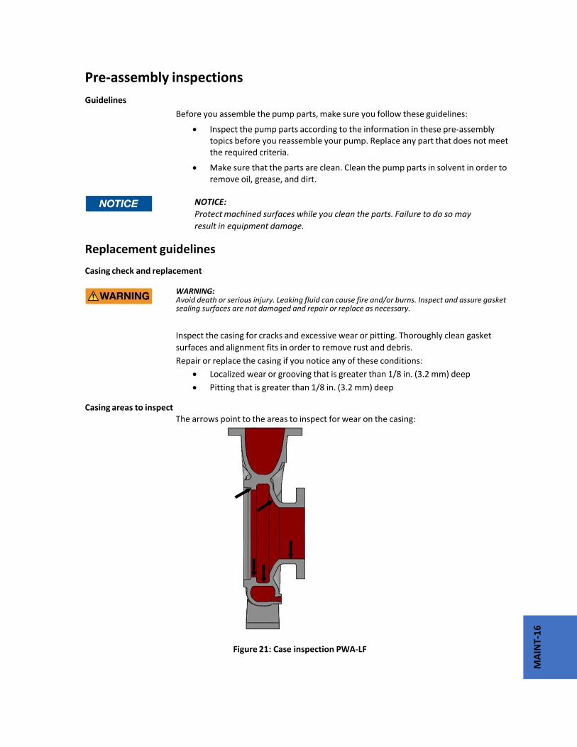
MAINT‐16
Pre‐assembly inspections
Guidelines
Before you assemble the pump parts, make sure you follow these guidelines:
Inspect the pump parts according to the information in these pre‐assembly topics before you reassemble your pump. Replace any part that does not meet the required criteria.
Make sure that the parts are clean. Clean the pump parts in solvent in order to remove oil, grease, and dirt.
NOTICE:
Protect machined surfaces while you clean the parts. Failure to do so may
result in equipment damage.
Replacement guidelines
Casing check and replacement
WARNING: Avoid death or serious injury. Leaking fluid can cause fire and/or burns. Inspect and assure gasket sealing surfaces are not damaged and repair or replace as necessary.
Inspect the casing for cracks and excessive wear or pitting. Thoroughly clean gasket
surfaces and alignment fits in order to remove rust and debris.
Repair or replace the casing if you notice any of these conditions:
Localized wear or grooving that is greater than 1/8 in. (3.2 mm) deep
Pitting that is greater than 1/8 in. (3.2 mm) deep
Casing areas to inspect The arrows point to the areas to inspect for wear on the casing:
Figure 21: Case inspection PWA‐LF

MAINT‐17
Impeller replacement Table 6: Replacing the impeller
Inspection Area When to replace
Impeller vanes • When grooved deeper than 1/16 in. (1.6 mm), or
• When worn evenly more than 1/32 in. (0.8 mm)
Pumpout vanes (back of impeller) When worn more than 1/32 in. (0.8 mm)
Vane edges Cracks, pitting, or corrosion damage
Impeller areas to inspect
Figure 22: Areas to inspect for wear on the PWA‐LF impeller.
Labyrinth seal replacement
Replace the labyrinth seal O‐ring if it has cuts and cracks. Replace the entire labyrinth‐seal assembly if it is damaged or bent. Rotate the seal several times by hand before installation. If it does not spin smoothly, it should be replaced.
Gaskets and O‐ring replacement
WARNING: Avoid death or serious injury. Leaking fluid can cause fire and/or burns. Replace any damaged or worn gaskets/o‐rings.

MAINT‐18
Replace all gaskets and O‐rings at each overhaul and disassembly.
Shaft and sleeve replacement guidelines
Shaft measurements check
Replace the shaft (122) if any measurements exceed acceptable values. See Bearing fits
and tolerances.
Figure 23: Shaft run out inspection
Straightness check
Replace the shaft (122) if runout exceeds the values in this table:
Table 7: Shaft run out tolerances for sleeve fit and coupling fit
Sleeve fit in inches ( millimeters) Coupling fit in inches (millimeters)With sleeve 0.001 (0.025) 0.001 (0.025)
Without sleeve 0.002 (0.051) 0.001 (0.025)
Shaft and sleeve check
Check the shaft and sleeve (126) surface for grooves and pitting.
Replace the shaft and sleeve if any grooves or pits are found.
Bearing‐frame inspection Checklist
Check the bearing frame for these conditions:
Visually inspect the bearing frame and frame foot for cracks.
Check the inside surfaces of the frame for rust, scale, or debris. Remove all loose and foreign material.
Make sure that all lubrication passages are clear. If the frame has been exposed to pumped fluid, inspect the frame for corrosion or pitting.
Inspect the inboard‐bearing bores. If any bores are outside the measurements in the Bearing fits and tolerances table, replace the bearing frame.

MAINT‐19
Surface inspection locations
This figure shows the areas to inspect for wear on the bearing frame outside surface.
Figure 24: Outside & Inside surface inspection locations – bearing frame
Seal chamber and casing cover inspection Checklist
Perform these checks when you inspect the seal chamber and stuffing box cover:
Make sure that these surfaces are clean: 1) Seal chamber and stuffing box cover 2) Mounting
Replace the seal chamber and stuffing box cover if pitting or wear exceeds 1/8” (3.2 mm) deep.
Inspect the machined surfaces and mating faces noted in the figures. These images point to the areas to inspect:

MAINT‐20
Figure 25: Casing cover inspection areas ‐ Standard Bore
Figure 26: Casing cover inspection areas ‐ Big Bore

MAINT‐21
Figure 27: Casing cover inspection areas ‐ Taper Bore
Bearing‐housing inspection Checklist
Inspect the bearing‐housing (134) bore according to the bearing fits and tolerances table.
Replace the bearing housing if the dimensions exceed acceptable values. Reference: see Bearings fits and tolerances.
Visually inspect the bearing housing for cracks and pits. Checklist for specific models
Table 8: Bearing housing checks
Frame Bearing‐housing check
Group 1, 2, 3 Clean grooves, drain port and face

MAINT‐22
Inspection locations
The following images point to the areas to inspect on the bearing housing.
Figure 28: Inspection areas ‐ Group 1 and 2 bearing housing
Figure 29: Inspection areas ‐ Group 3 bearing housing

MAINT‐23
Bearing fits and tolerances Table 9: Bearing fits and tolerances table This table references the bearing fits and tolerances for the PWA, PWA‐LF and PWA‐SP
Group 1 inches (millimeters)
Group 2 inches (millimeters)
Group 3 inches (millimeters)
Shaft OD NDE
1.3785 (35.014) 1.3781 (35.004)
1.7722 (45.014) 1.7718 (45.004)
2.1660 (55.016) 2.1655 (55.004)
Bearing ID NDE
1.3780 (35.001) 1.3775 (34.989)
1.7717 (45.001) 1.7712 (44.988)
2.1654 (55.001) 2.1648 (54.986)
FIT 0.0010 (0.025) tight 0.0001 (0.003) tight
0.0010 (0.025) tight 0.0001 (0.003) tight
0.0012 (0.030) tight 0.0001 (0.003) tight
Frame ID NDE
2.8358 (72.029) 2.8351 (72.011)
3.9384 (100.035) 3.9375 (100.013)
4.7258 (120.035) 4.7249 (120.012)
Bearing OD NDE
2.8346 (72.000) 2.8341 (71.986)
3.9370 (100.000) 3.9364 (99.985)
4.7244 (120.000) 4.7238 (119.985)
FIT 0.0017 (0.043) loose
0.0005 (0.013) loose
0.0020 (0.051) loose
0.0005 (0.013) loose
0.0020 (0.051) loose
0.0005 (0.013) loose
Shaft OD DE
1.1815 (30.010) 1.1812 (30.002)
1.7722 (45.014) 1.7718 (45.004)
1.9690 (50.013) 1.9686 (50.003)
Bearing ID DE
1.1811 (30.000) 1.1807 (29.990)
1.7717 (45.001) 1.7712 (44.988)
1.9685 (50.000) 1.9680 (49.987)
FIT 0.0008 (0.020) tight 0.0001 (0.003) tight
0.0010 (0.025) tight 0.0001 (0.003) tight
0.0010 (0.025) tight 0.0001 (0.003) tight
Housing ID DE
2.8358 (72.029) 2.8351 (72.011)
3.9384 (100.035) 3.9375 (100.013)
4.3321 (110.035) 4.3312 (110.012)
Bearing OD DE
2.8346 (72.000) 2.8341 (71.986)
3.9370 (100.000) 3.9364 (99.985)
4.3307 (110.000) 4.3301 (109.985)
FIT 0.0017 (0.043) loose
0.0005 (0.013) loose
0.0020 (0.051) loose
0.0005 (0.013) loose
0.0020 (0.051) loose
0.0005 (0.013) loose
Reassembly General Considerations
CAUTION: Wear insulated gloves when you use a bearing heater. Bearings get hot and can cause physical injury.
NOTICE:
Make sure that the pipe threads are clean, and that you apply thread sealant to the
plugs and fittings. Failure to do so may result in equipment damage.
NOTICE: Only use a degaussing induction heater or precision oven to warm bearings for assembly. Improper bearing heating can significantly affect bearing life and pump performance.

MAINT‐24
Assemble the rotating element and the bearing frame (Group 1 & 2)
1. Prepare the bearing frame (228) as follows (see the illustration): a) Install the oil‐fill plug (113B). b) Install the oil‐drain plug (408A). c) Install the sight glass (319). d) Install the sight oiler plug (408J). e) Install the plug for the oil‐cooler inlet (408L). f) Install the plug for the oil‐cooler outlet (408M). g) Install two oil‐mist connection plugs (408H). Or: Install two grease fittings (193) and two grease‐relief plugs (113) h) Attach the bearing‐frame foot (241) and fasten the bolts (370F) by hand.
Figure 30: Assemble the bearing frame and foot 2. Install the outboard bearing (112A) on the shaft (122). The regreaseable bearing has a single shield. The outboard bearing is installed with the shield toward the impeller. a) Inspect the shaft (122) to ensure that it is clean, dimensionally correct, and is free of nicks and burrs. b) Lightly coat the bearing seating with a thin film of oil. c) Remove the bearing (112A) from its packaging. d) Wipe the preservative from the bearing (112A) bore and outer diameter e) Use an induction heater with a demagnetizing cycle to heat the bearing (112A) to an inner ring temperature of 230 °F (110 °C). f) Position the bearing (112A) on the shaft (122) against the shoulder and snug the locknut (136) against the bearing until it is cool. The locknut prevents the bearing from moving away from the shaft shoulder as it cools. g) Remove the bearing locknut (136) after the bearing (112A) cools to room temperature. 3. Put the lock washer (382) onto the shaft (122). 4. Thread the locknut (136) onto the shaft (122) and tighten it until it is tight. 5. Bend the tangs of the lock washer into the slots of the locknut.
228

MAINT‐25
6. Make sure that the flat side of the snap ring is towards the bearing. 7. Coat the inner surfaces of the bearings with lubricant. 8. Install flinger disk (248) onto shaft. 9. Put the inboard bearing (168) onto the shaft (122). The regreaseable bearing has a single shield. Make sure that the bearing is installed with the shield away from the impeller.
Figure 31: Shaft Assembly 10. Prepare the shaft for assembly as follows:
a) Install a new O‐ring (496). b) Coat the outside of the outboard bearing (112A) with oil. c) Coat the bore of the bearing housing (134) with oil. d) Put the bearing housing (134) onto the shaft. Do not use force. e) Insert the bearing‐retaining ring (361A) into the bore groove of the bearing housing (134). NOTICE:
Ensure that the space between the ends of the retaining ring are located such that the oil return groove is not obstructed. Return groove obstruction can cause reduced bearing life. Make sure that the shaft rotates freely. f) Install the outboard labyrinth oil‐seal (332A) into the bearing housing (134). Place the drain slots of the oil seal at the bottom position (6 o’clock). Make sure that the edges of the keyway are free from burrs. To protect the O‐ ring, cover the keyway lengthwise with a piece of electrical tape before you install the oil seal.

MAINT‐26
Figure 32: Shaft assembly installation
11. Install the shaft assembly into the bearing frame as follows (see the illustration): a) Coat the outside of the bearing housing (134) with light oil. b) Coat all the internal surfaces of the bearing frame (228) with light oil. c) Install the shaft assembly into the bearing frame (228). Make sure that the shaft rotates freely. d) Install the clamp bolts (370C) in the bearing housing (134) and tighten by hand. e) Install the jack bolts (370D) with the locknuts (423) in the bearing housing (134) and tighten by hand.
Assemble the rotating element and the bearing frame (Group 1 and 2 with duplex bearings)
1. Prepare the bearing frame (228) as follows (see the illustration): a) Install the oil‐fill plug (113B). b) Install the oil‐drain plug (408A). c) Install the sight glass (319). d) Install the plug‐oiler (408J). e) Install the plug for the oil‐cooler inlet (408L). f) Install the plug for the oil‐cooler outlet (408M). g) Install two oil‐mist connection plugs (408H). Or: Install two grease fittings (193) and two grease‐relief plugs (113). h) Attach the bearing‐frame foot (241) and fasten the bolts (370F) by hand.
228

MAINT‐27
Figure 33: Assemble the bearing frame and foot – duplex bearing
2. Install flinger disk (248), clamping ring (253B) making sure the orientation is correct, and the outboard bearings (112A) on to the shaft (122). The re‐greasable bearing has a single shield. Make sure that the bearing is installed with the shield away from the impeller. The duplex bearings are mounted back‐to‐back. Make sure that the orientation of the bearings is correct. a) Inspect the shaft (122) to ensure that it is clean, dimensionally correct, and is free of nicks and burrs.
Figure 34: Duplex bearing installation b) Lightly coat the bearing seating with a thin film of oil. c) Remove the bearings (112A) from their packaging. d) Wipe the preservative from the bearing (112A) bore and outer diameter. e) Use an induction heater with a demagnetizing cycle to heat both bearings (112) to an inner ring temperature of 230 °F (110 °C). f) Place both bearings (112A) on the shaft (122) with the large outer races together (back‐ to‐back). g) Position the bearings (112A) on the shaft (122) against the shoulder and snug the locknut (136) against the bearings until they are cool. The locknut prevents the bearings from moving away from the shaft shoulder as they cool. Rotate the outer bearing rings relative to each other as they are placed on the shaft to assure good alignment. h) Remove the bearing locknut (136) after the bearings (112A) are cool.
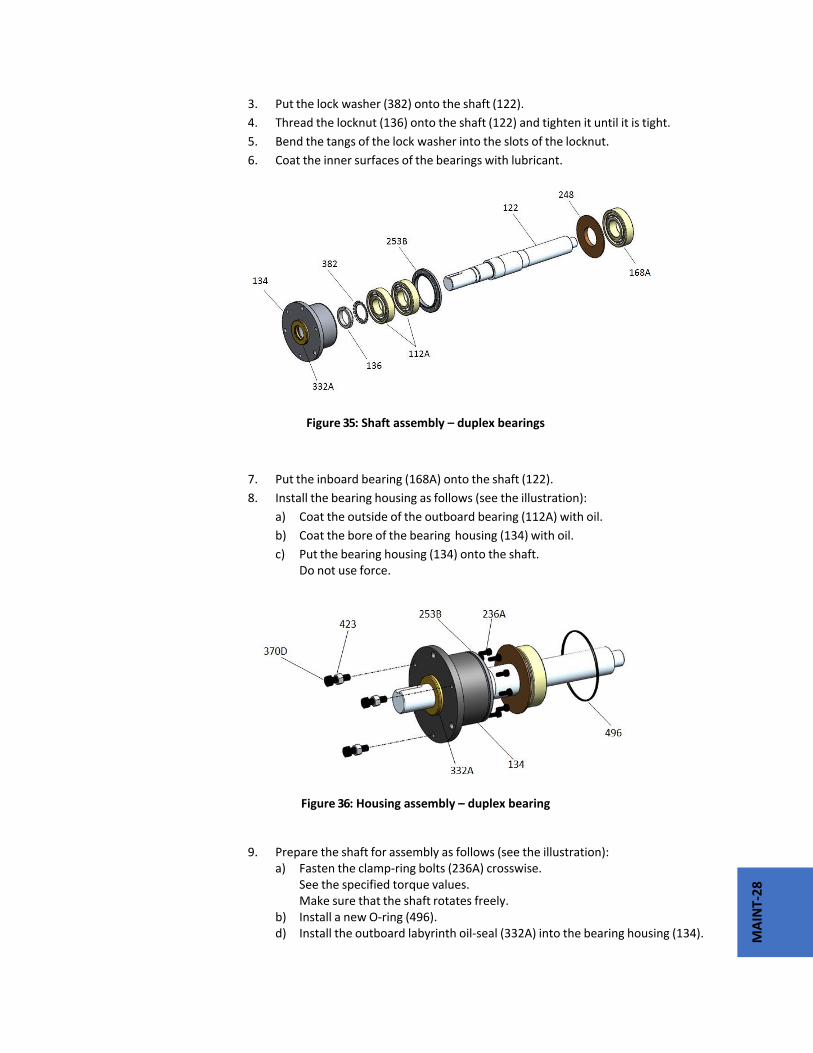
MAINT‐28
3. Put the lock washer (382) onto the shaft (122).
4. Thread the locknut (136) onto the shaft (122) and tighten it until it is tight.
5. Bend the tangs of the lock washer into the slots of the locknut.
6. Coat the inner surfaces of the bearings with lubricant.
Figure 35: Shaft assembly – duplex bearings
7. Put the inboard bearing (168A) onto the shaft (122).
8. Install the bearing housing as follows (see the illustration):
a) Coat the outside of the outboard bearing (112A) with oil.
b) Coat the bore of the bearing housing (134) with oil.
c) Put the bearing housing (134) onto the shaft. Do not use force.
Figure 36: Housing assembly – duplex bearing
9. Prepare the shaft for assembly as follows (see the illustration):
a) Fasten the clamp‐ring bolts (236A) crosswise. See the specified torque values. Make sure that the shaft rotates freely. b) Install a new O‐ring (496). d) Install the outboard labyrinth oil‐seal (332A) into the bearing housing (134).
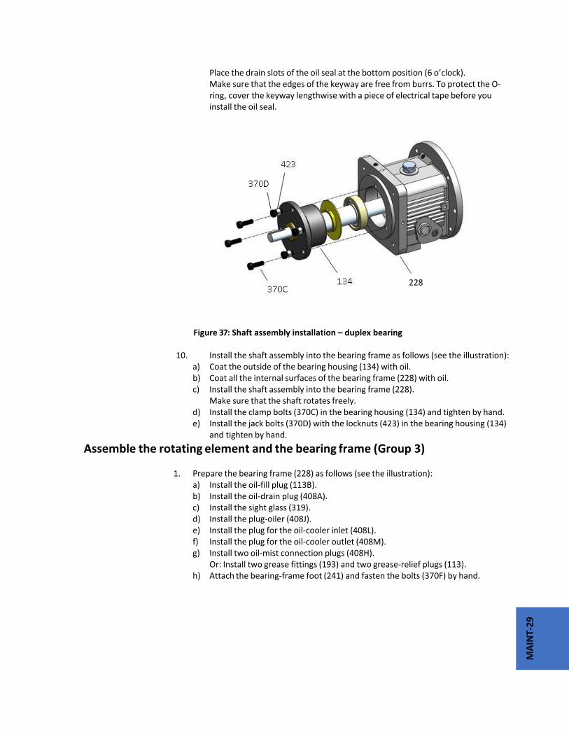
MAINT‐29
Place the drain slots of the oil seal at the bottom position (6 o’clock). Make sure that the edges of the keyway are free from burrs. To protect the O‐ ring, cover the keyway lengthwise with a piece of electrical tape before you install the oil seal.
Figure 37: Shaft assembly installation – duplex bearing 10. Install the shaft assembly into the bearing frame as follows (see the illustration): a) Coat the outside of the bearing housing (134) with oil. b) Coat all the internal surfaces of the bearing frame (228) with oil. c) Install the shaft assembly into the bearing frame (228). Make sure that the shaft rotates freely. d) Install the clamp bolts (370C) in the bearing housing (134) and tighten by hand. e) Install the jack bolts (370D) with the locknuts (423) in the bearing housing (134) and tighten by hand.
Assemble the rotating element and the bearing frame (Group 3) 1. Prepare the bearing frame (228) as follows (see the illustration): a) Install the oil‐fill plug (113B). b) Install the oil‐drain plug (408A). c) Install the sight glass (319). d) Install the plug‐oiler (408J). e) Install the plug for the oil‐cooler inlet (408L). f) Install the plug for the oil‐cooler outlet (408M). g) Install two oil‐mist connection plugs (408H). Or: Install two grease fittings (193) and two grease‐relief plugs (113). h) Attach the bearing‐frame foot (241) and fasten the bolts (370F) by hand.
228

MAINT‐30
Figure 38: Assemble the bearing frame and foot – Group 3 2. Install the oil flinger (248) onto the shaft (122). NOTICE: The oil flinger is press fitted onto the shaft. Use a properly sized driver. Failure to do so may result in damage to the oil flinger. 3. Place the bearing‐clamp ring (253B) onto the shaft (122). Make sure that the orientation of the bearing‐clamp ring is correct. 4. Install outboard bearings (112A) on shaft (122). The regreaseable bearing has a single shield. Make sure that the bearing is installed with the shield away from the impeller. The duplex bearings are mounted back‐to‐back. Make sure that the orientation of the bearings are correct. a) Inspect the shaft (122) to ensure that it is clean, dimensionally correct, and is free of nicks and burrs.
Figure 39: Duplex bearing assembly – Group 3
b) Lightly coat the bearing seating with a thin film of oil. c) Remove the bearings (112A) from their packaging. d) Wipe the preservative from the bearing (112A) bore and outer diameter. e) Use an induction heater with a demagnetizing cycle to heat both bearings (112) to an inner ring temperature of 230 °F (110 °C). f) Place both bearings (112A) on the shaft (122) with the large outer races together (back‐ to‐back).
228
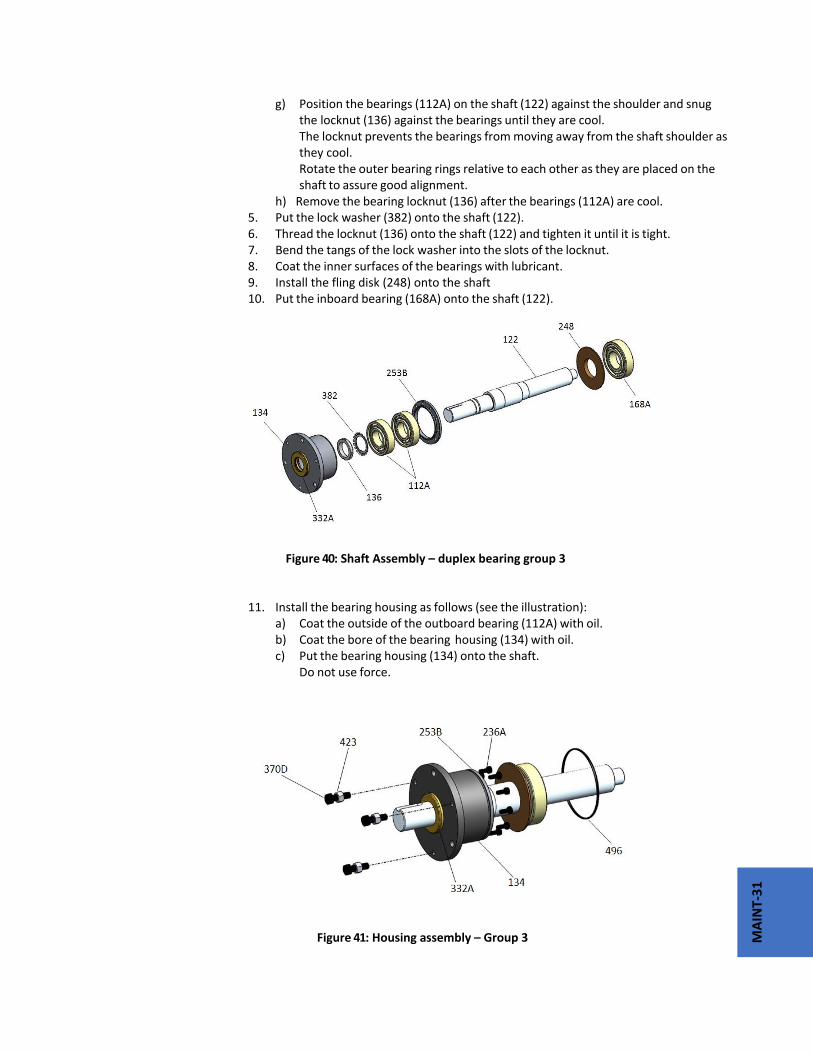
MAINT‐31
g) Position the bearings (112A) on the shaft (122) against the shoulder and snug the locknut (136) against the bearings until they are cool. The locknut prevents the bearings from moving away from the shaft shoulder as they cool. Rotate the outer bearing rings relative to each other as they are placed on the shaft to assure good alignment. h) Remove the bearing locknut (136) after the bearings (112A) are cool. 5. Put the lock washer (382) onto the shaft (122). 6. Thread the locknut (136) onto the shaft (122) and tighten it until it is tight. 7. Bend the tangs of the lock washer into the slots of the locknut. 8. Coat the inner surfaces of the bearings with lubricant. 9. Install the fling disk (248) onto the shaft 10. Put the inboard bearing (168A) onto the shaft (122).
Figure 40: Shaft Assembly – duplex bearing group 3 11. Install the bearing housing as follows (see the illustration): a) Coat the outside of the outboard bearing (112A) with oil. b) Coat the bore of the bearing housing (134) with oil. c) Put the bearing housing (134) onto the shaft. Do not use force.
Figure 41: Housing assembly – Group 3
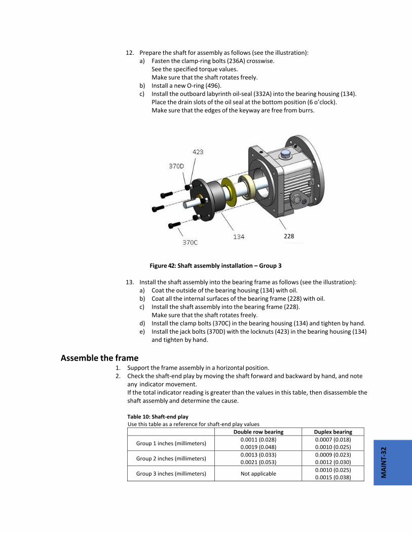
MAINT‐32
12. Prepare the shaft for assembly as follows (see the illustration): a) Fasten the clamp‐ring bolts (236A) crosswise. See the specified torque values. Make sure that the shaft rotates freely. b) Install a new O‐ring (496). c) Install the outboard labyrinth oil‐seal (332A) into the bearing housing (134). Place the drain slots of the oil seal at the bottom position (6 o’clock). Make sure that the edges of the keyway are free from burrs.
Figure 42: Shaft assembly installation – Group 3 13. Install the shaft assembly into the bearing frame as follows (see the illustration): a) Coat the outside of the bearing housing (134) with oil. b) Coat all the internal surfaces of the bearing frame (228) with oil. c) Install the shaft assembly into the bearing frame (228). Make sure that the shaft rotates freely. d) Install the clamp bolts (370C) in the bearing housing (134) and tighten by hand. e) Install the jack bolts (370D) with the locknuts (423) in the bearing housing (134) and tighten by hand.
Assemble the frame 1. Support the frame assembly in a horizontal position. 2. Check the shaft‐end play by moving the shaft forward and backward by hand, and note
any indicator movement. If the total indicator reading is greater than the values in this table, then disassemble the
shaft assembly and determine the cause. Table 10: Shaft‐end play
Use this table as a reference for shaft‐end play values
Double row bearing Duplex bearing
Group 1 inches (millimeters) 0.0011 (0.028) 0.0019 (0.048)
0.0007 (0.018) 0.0010 (0.025)
Group 2 inches (millimeters) 0.0013 (0.033) 0.0021 (0.053)
0.0009 (0.023) 0.0012 (0.030)
Group 3 inches (millimeters) Not applicable 0.0010 (0.025) 0.0015 (0.038)
228
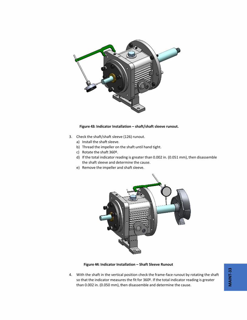
MAINT‐33
Figure 43: Indicator Installation – shaft/shaft sleeve runout.
3. Check the shaft/shaft sleeve (126) runout.
a) Install the shaft sleeve.
b) Thread the impeller on the shaft until hand tight.
c) Rotate the shaft 360º.
d) If the total indicator reading is greater than 0.002 in. (0.051 mm), then disassemble
the shaft sleeve and determine the cause.
e) Remove the impeller and shaft sleeve.
Figure 44: Indicator Installation – Shaft Sleeve Runout
4. With the shaft in the vertical position check the frame‐face runout by rotating the shaft
so that the indicator measures the fit for 360º. If the total indicator reading is greater
than 0.002 in. (0.050 mm), then disassemble and determine the cause.

MAINT‐34
Figure 45: Indicator installation – frame face runout
5. Place the plastic gasket (360D) on the frame (228), and hold the gasket in place by
inserting the dowel pins (469B) in their holes.
The gasket is designed to fit only one way.
6. Install the frame adapter.
a) Place the frame adapter (108) onto the frame assembly.
b) Align the bolt holes and dowel locations on the frame adapter with the bolt holes and
dowel locations on the frame.
Figure 46: Frame adapter installation
469B

MAINT‐35
d) Rotate the shaft 360º to check the adapter fit.
If the total indicator reading is greater than 0.005 in. (0.13 mm), then determine the
cause and correct it before you proceed.
Figure 47: Indicator installation – Frame adapter runout
7. Install the labyrinth oil‐seal (333A) into the adapter (108) and the bearing frame (228).
The labyrinth oil seal is an O‐ring fit.
8. Position the labyrinth oil‐seal drain slots at the bottom (6 o’clock) position.
Figure 48: Labyrinth oil seal installation
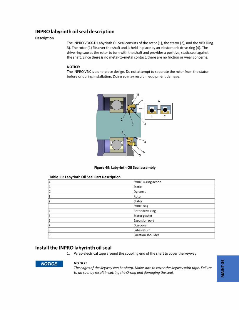
MAINT‐36
INPRO labyrinth oil seal description Description The INPRO VBXX‐D Labyrinth Oil Seal consists of the rotor (1), the stator (2), and the VBX Ring 3). The rotor (1) fits over the shaft and is held in place by an elastomeric drive ring (4). The drive ring causes the rotor to turn with the shaft and provides a positive, static seal against the shaft. Since there is no metal‐to‐metal contact, there are no friction or wear concerns. NOTICE: The INPRO VBX is a one‐piece design. Do not attempt to separate the rotor from the stator before or during installation. Doing so may result in equipment damage.
Figure 49: Labyrinth Oil Seal assembly
Table 11: Labyrinth Oil Seal Part Description
Install the INPRO labyrinth oil seal
1. Wrap electrical tape around the coupling end of the shaft to cover the keyway. NOTICE: The edges of the keyway can be sharp. Make sure to cover the keyway with tape. Failure to do so may result in cutting the O‐ring and damaging the seal.
A "VBX" O‐ring action
B Static
C Dynamic
1 Rotor
2 Stator
3 "VBX" ring
4 Rotor drive ring
5 Stator gasket
6 Expulsion port
7 D groove
8 Lube return
9 Location shoulder

MAINT‐37
2. Lightly lube the shaft and the drive ring (4) with lubricant. Lubricant helps in the installation process. Be sure that the lubricant is compatible with the O‐ring material and the pump‐system standards. 3. Use an arbor press to install the outboard INPRO VBXX‐D into the bearing cover with the expulsion port (6) at the 6 o'clock position. Press the outboard INPRO VBXX‐D down to where the stator location ramp (9) starts to avoid angular misalignment. There is a nominal 0.002 in. (0.051 mm) interference fit. 4. Discard any residual material from the stator gasket (5). 5. Complete the applicable step in this table depending on the model of your pump.
Table 12: Labyrinth oil‐seal installation
Pump model Action
Group 1 Press the inboard seal along the shaft into the bearing frame.
All other models After you install the frame adapter on the bearing frame, press the inboard seal over the shaft and into the adapter.
Shaft sealing with cartridge mechanical seal
Seal the shaft with a packed stuffing box Pumps are shipped without the packing, lantern ring, or split gland installed. These parts are included with the box of fittings shipped with each pump and must be installed before startup. 1. Carefully clean the stuffing‐box bore. 2. Twist the packing enough to get it around the shaft. Packing Rings
Correct Incorrect Lantern Rings Correct Incorrect 3. Insert the packing and stagger the joints in each ring by 90°.

MAINT‐38
Install the stuffing‐box parts in this order: a) Two packing rings b) One lantern ring (two‐piece) c) Three packing rings NOTICE: Make sure that the lantern ring is located at the flushing connection to ensure that flush is obtained. Failure to do so may result in decreased performance. 4. Install the gland halves and evenly hand‐tighten the nuts.
Seal the shaft 1. Slide the cartridge seal onto the shaft or sleeve until it contacts the inboard labyrinth oil seal. 2. Install the seal chamber. 3. Slide the cartridge seal into the seal chamber and secure using the four studs and nuts. 4. Continue with the pump reassembly. 5. Set the impeller clearance. Refer to the Impeller clearance setting topic for more information. 6. Tighten the setscrews in the seal locking ring in order to secure the seal to the shaft. 7. Remove the centering clips from the seal.
Seal the shaft with a cartridge mechanical seal 1. Assemble the seal chamber: a) Install a seal‐chamber cover or a backplate (184) and fasten with nuts (370H).
Figure 50: Mechanical Seal installation
b) Check the seal‐chamber cover runout.

MAINT‐39
Figure 51: Seal‐chamber cover runout inspection
Rotate the indicator through 360º. If the total indicator reading is greater than 0.005 inches (0.13 mm), determine the cause and correct the issue before you proceed.
c) Install the shaft sleeve (126).
Figure 52: Shaft Sleeve installation

MAINT‐40
2. Continue the complete reassembly of the pump, do not install Teflon o‐ring (412A) at this point. 3. Set the impeller clearance. Refer to the Impeller clearance setting section for more information. 4. Scribe a line on the marked shaft and sleeve at the face of the seal chamber. 5. Remove the casing, the impeller, and the seal chamber. 6. Install the gland, with the stationary seat and gland gaskets installed. 7. Install the mechanical‐seal rotary unit per the manufacturer's instructions. Use the scribed line as the seal‐reference dimension. Be sure to secure the rotary unit in place using the set screws in the locking ring. 8. Reinstall the seal chamber and attach gland. 9. Install Teflon impeller o‐ring (412A). 10. Complete the reassembly of the pump.
Install the impeller
1. Install the impeller.
Table 13: Impeller installation
2. Attach a shaft wrench and a coupling key on the shaft. a) When the impeller (101) makes firm contact with the shaft or sleeve (126), raise the shaft wrench (counterclockwise, viewed from the impeller end of the shaft) off of the bench and slam it down (clockwise, viewed from the impeller end of shaft).
3. Attach a shaft wrench and a coupling key on the shaft.
a) With the impeller (101) firmly mounted against the sleeve (126), rapidly rotate the shaft wrench (clockwise, viewed from the drive end of the shaft) so that the wrench forcefully hits the work bench.
b) Repeat “step a” until impeller (101) is tight.
Pump size Action
Group 1,2,3 Install the impeller (101). Use a new impeller O‐ring (412A).

MAINT‐41
Figure 53: Impeller installation
4. Loosen the clamp bolts (370C) and the jack bolts (370D). 5. Measure the gap between the impeller (101) and the seal chamber and casing cover
(184) with a feeler gauge.
Figure 54: Setting impeller clearance
6. When you reach 0.030 in. (0.76 mm) clearance, tighten the clamp bolts (370C), jack bolts (370D), and lock nuts (423). Perform a final impeller adjustment after you install the impeller into the casing

MAINT‐42
For more information on how to set the impeller clearances, refer to the impeller
clearance checks and impeller clearance setting sections in Commissioning, Startup, Operation, and Shutdown.
Install the back pull‐out assembly
1. Clean the casing fit and install the casing gasket (351) on the seal chamber /
stuffing‐ box cover.
2. Loosen the clamping bolts (370C) and jack bolts (370D) on the bearing housing.
3. Install the back pull‐out assembly in the casing.
4. Install casing bolts (370) and hand tighten, then tighten to appropriate torque
values in table 14.
Refer to the bolt torque values for information on how to tighten the casing
bolts.
5. Install and tighten the casing jackscrews (418).
NOTICE:
Do not over tighten the casing jackscrews. Doing so may result in equipment
damage.
7. Check the total clearance of the impeller in the casing.
With new parts, an acceptable range is 0.030 in. (0.76 mm) to 0.065 in. (1.65
mm). If the impeller clearance is outside of this range, you either have the
incorrect parts, an improper installation, or too much pipe strain. Determine the
cause and correct the problem before you proceed.
8. Adjust the impeller clearance.
Refer to the Impeller clearance setting section for more information.
9. Replace the auxiliary piping.
10. Fill the pump with the proper lubricant. See Lubricating‐oil requirements.
11. Reinstall the coupling guard.
See Install the coupling guard for more information.
NOTICE:
Risk of damage to the mechanical seal or shaft sleeve on units supplied with cartridge
mechanical seals. Prior to startup, make sure to tighten the set screws in the seal
locking ring and remove the centering clips.
Post‐assembly checks Perform these checks after you assemble the pump, then continue with pump startup:
Rotate the shaft by hand in order to make sure that it rotates easily and smoothly and that there is no rubbing.
Open the isolation valves and check the pump for leaks.
Assembly references

MAINT‐43
Bolt torque values Table 14: Bolt torque, lb‐ft (Nm)
This table provides the bolt torque values.
Location Frame Lube Dry
Casing bolts (370) or casing nuts (425)
6 inch, Group 1 N/A N/A
8 inch, Group 1 35 (47) 53 (71)
Group 2, 3 35 (47) 53 (71)
Frame‐to adapter bolts
All 20 (27) 30 (40)
Bearing‐clamp ring bolts (236A) – duplex bearing only
Group 1, 2 *10 (1.1) *17 (1.9)
Group 3 *55 (6.2) *83 (9.4)
Bearing housing clamp bolt (370C) and jacking bolt (370D)
Group 1, 2, 3 35 (47) 53 (71)
*Values are in ib‐in (Nm)
Table 15: Maximum torque values in lb‐ft (Nm) for casing bolts This table provides the maximum torque values for casing bolts.
Models PWA, PWA‐LF, PWA‐SP with 150 lb (68 kg) casing flanges
Material specification
Carbon Steel casing with A307 Grade B casing bolts
Alloy casing with (304SS) F593 Grade 1 or (316SS F593) Grade 2 casing bolts
Frame Casing bolt diameter (in.)
Lube Dry Lube Dry
8 inch, Group 1 0.50 20 (27) 30 (41) 35 (47) 54 (73)
6 inch Group 1,
Group 2 & 3
Group. 4
0.625 39 (53) 59 (80) 71 (96) 107 (145)
0.625 39 (53) 59 (80) 71 (96) 107 (145)
0.625 39 (53) 59 (80) 71 (96) 107 (145)
0.625 39 (53) 59 (80) 71 (96) 107 (145)
Bearing types Table 16: Bearing types
Frame Double Row
Inboard bearing duplex
Outboard bearing
Double Row Duplex
Group 1 6 3 7
Group 2 6 3 7
Group 3 6 N/A 7
Spare parts Pump Serial Number is REQUIRED for all Parts Orders. This ensures the correct
material and design for your specific pump unit.
Impeller (101)

MAINT‐44
Shaft (122A)
Shaft sleeve (126)
Outboard bearing (112A)
Inboard bearing (168A)
Casing gasket (351)
Frame‐to‐adapter gasket (360D)
Bearing‐housing retaining ring (361A)
Bearing lock washer (382)
Bearing locknut (136)
Impeller O‐ring (412A)
Bearing‐housing O‐ring (496)
Outboard labyrinth‐seal rotary O‐ring (497F)
Outboard labyrinth‐seal stationary O‐ring (497G)
Inboard labyrinth‐seal rotary O‐ring (497H)
Inboard labyrinth‐seal stationary O‐ring (497J)
Lantern ring half (105) (packed stuffing box)
Stuffing box packing (106) (packed stuffing box)
Packing gland (107) (packed stuffing box)
Impeller gasket (42)

PARTS
-1
Parts Listings and Cross‐Sectional Drawings

PARTS
-2
Table 1 ‐ Parts List
Item Quantity Part name100 1 Casing101 1 Impeller105 1 Lantern Ring108 1 Frame Adapter112A 1 Outboard Bearing113 2 Plug—Grease Relief113B 1 Plug—Oil Fill122A 1 Shaft—Without Sleeve122 1 Shaft—With Sleeve126 1 Shaft Sleeve134 1 Bearing Housing136 1 Bearing Locknut168A 1 Radial Bearing184 1 Seal Chamber/Stuffing Box Cover193 2 Grease Fitting228 1 Bearing Frame236A 10 Cap Screw—Bearing Clamp Ring239 1 Support, Casing241 1 Frame Foot248 1 Flinger Disk250 1 Gland—Mechanical Seal253B 1 Bearing Clamp Ring332A 1 Outboard Labyrinth Seal w/O‐rings333A 1 Inboard Labyrinth Seal w/O‐rings351 1 Casing Gasket353 4 Gland Stud355 4 Gland Stud Nut358 1 Plug—Casing Drain360D 1 Gasket—Frame‐to‐Adapter360Q 1 Gasket—Gland‐to‐Stuffing Box Cover361A 1 Retaining Ring370 ** Bolt – Adapter to Case370B 4 Bolt—Frame‐to‐Adapter370C 3 Clamp Bolt—Bearing Housing370D 3 Jack Bolt—Bearing Housing370F 2 Bolt—Frame Foot to Frame370H 2 Stud—Stuffing Box Cover‐to‐Adapter370Y 2 Bolt—Cap Casing to Support382 1 Bearing Lockwasher383 1 Mechanical Seal400 1 Coupling Key408A 1 Plug—Oil Drain 408H 2 Plug—Oil Mist Connection408J 1 Plug—Oiler408L 1 Plug—Oil Cooler Inlet408M 1 Plug—Oil Cooler Outlet408N 2 Plug—Sight Glass412A 1 O‐Ring, Teflon Impeller418 3 Jack Bolt—Adapter‐to‐Case
423 3 Jam Nut—Bearing Housing Jack Bolt423B 2 Hex Nut—Stuffing Box Cover to Adapter
428 1 Gasket, Plug437 1 Lockwasher, Casing to Support469B 2 Dowel Pin—Frame‐to‐Adapter496 1 O‐Ring Bearing Housing497F 1 O‐Ring—Outboard Labyrinth Rotor497G 1 O‐Ring—Outboard Labyrinth Stator497H 1 O‐Ring—Inboard Labyrinth Rotor
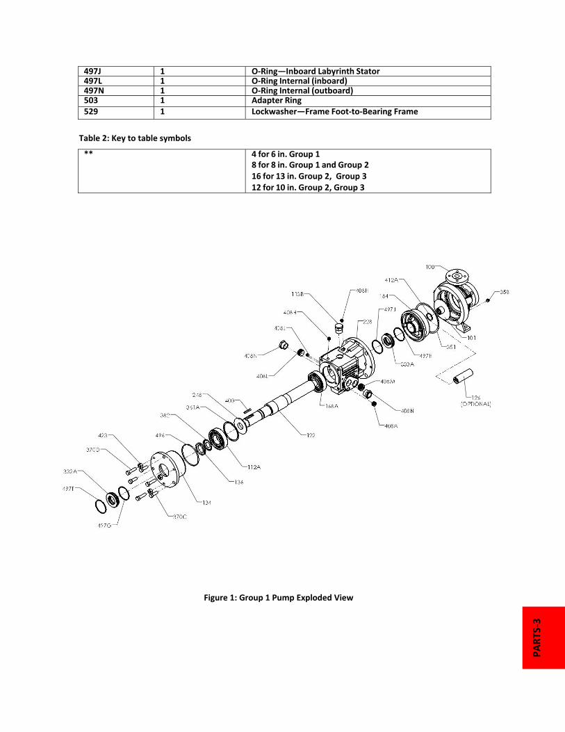
PARTS
-3
497J 1 O‐Ring—Inboard Labyrinth Stator497L 1 O‐Ring Internal (inboard)497N 1 O‐Ring Internal (outboard)503 1 Adapter Ring529 1 Lockwasher—Frame Foot‐to‐Bearing Frame
Table 2: Key to table symbols
** 4 for 6 in. Group 18 for 8 in. Group 1 and Group 2 16 for 13 in. Group 2, Group 3 12 for 10 in. Group 2, Group 3
Figure 1: Group 1 Pump Exploded View

PARTS
-4
Figure 2: Group 2 Pump Exploded View
Figure 3: Group 3 Pump Exploded View

Visit our website for more information.
www.bestpumpworksindustrial.com
See our other products at:
www.bestpumporks.com
www.pumpworks610.com
65 Southbelt Industrial Drive
Houston, TX 77047
U.S.A.
Ph: (713) 892‐5875
Fx: (713) 343‐0765
ELECTRONIC PUMP ON DEMAND