t440 barbecue - masterchefbbqs.com · t440 . barbecue. assembly manual. 85-3004-2 (g45118) propane...
TRANSCRIPT

T440 Barbecue Assembly Manual
85-3004-2 (G45118) Propane 85-3005-0 (G45119) Natural Gas
1 YEAR LIMITED WARRANTY
READ AND SAVE MANUAL FOR FUTURE REFERENCE. If pre-assembled, leave this manual with unit for
consumer’s future reference.
For product inquiries, parts, warranty and troubleshooting support, please call 1-877-707-5463.
Manual Revision #: 30082011 PD
1
DANGER1. If you smell Gas:
a. Shut off gas to the appliance b. Extinguish any open flame c. Open lid d. If odor continues, keep away from the appliance and immediately call your gas supplier or your fire department
2. Requires two people to complete the assembly process.
3. Beware of sharp edges.
WARNINGFailure to follow all of the Manufacturer’s instructions could result in hazardous fires, explosions, property damage, or serious personal injury or even death.
Follow all leak check procedures carefully prior to operation of barbecue, even if grill was dealer assembled. Do not try to light this barbecue without reading the Lighting Instructions section of this manual.
THIS MANUAL MUST REMAIN WITH THE PRODUCT AT ALL TIMES
CAUTIONRead and follow all safety statements, assembly instructions, use and care directions before attempting to assemble and cook.
WARNING1. Do not store or use gasoline or other
flammable liquids or vapours in the vicinity of this or any other appliance.
2. An LP cylinder not connected for use shall not be stored in the vicinity of this or any other appliance.
CAUTIONSharp edges. Wear gloves when assembling your grill.
T H I S B A R B E C U E I S F O R O U T D O O R U S E O N L Y
CO N TAC T C A L L C E N T R E I F A NY PA RTS A R E M I S S I N G
1 - 8 7 7 - 7 0 7 - 5 4 6 3
INSTALLER OR ASSEMBLER/CONSUMERThis manual should be kept with the BBQ at all times.
H E A V Y A R T I C L E N E E D S 2 T O L I F T
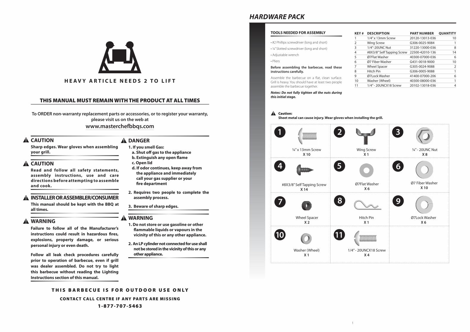
TOOLS NEEDED FOR ASSEMBLY
• #2 Phillips screwdriver (long and short)
• ¼” Slotted screwdriver (long and short)
• Adjustable wrench
• Pliers
Before assembling the barbecue, read these instructions carefully.
Assemble the barbecue on a flat, clean surface. Grill is heavy. You should have at least two people assemble the barbecue together.
Notes: Do not fully tighten all the nuts during this initial stage.
Caution: Sheet metal can cause injury. Wear gloves when installing the grill.
HARDWARE PACK
¼” x 13mm Screw X 10
Hitch PinX 1
Wing ScrewX 1
#8X3/8” Self Tapping ScrewX 14
Ø7 Fiber Washer X 10
¼” - 20UNC NutX 8
Ø7Flat Washer X 6
Wheel SpacerX 2
Ø7Lock Washer X 6
1 2 3
4 5 6
7 8 9
10
Washer (Wheel)X 1
KEY # DESCRIPTION PART NUMBER QUANTITY 1 1/4” x 13mm Screw 20120-13013-036 102 Wing Screw G306-0025-9084 13 1/4”-20UNC Nut 31220-13000-036 84 #8X3/8” Self Tapping Screw 22500-42010-136 145 Ø7Flat Washer 40300-07000-036 66 Ø7 Fiber Washer G431-0018-9000 107 Wheel Spacer G305-0024-9088 28 Hitch Pin G306-0005-9088 19 Ø7Lock Washer 41400-07000-206 610 Washer (Wheel) 40300-08000-036 111 1/4” - 20UNCX18 Screw 20102-13018-036 4
11
1/4” - 20UNCX18 ScrewX 4
To ORDER non-warranty replacement parts or accessories, or to register your warranty, please visit us on the web at
www.masterchefbbqs.com
2 3
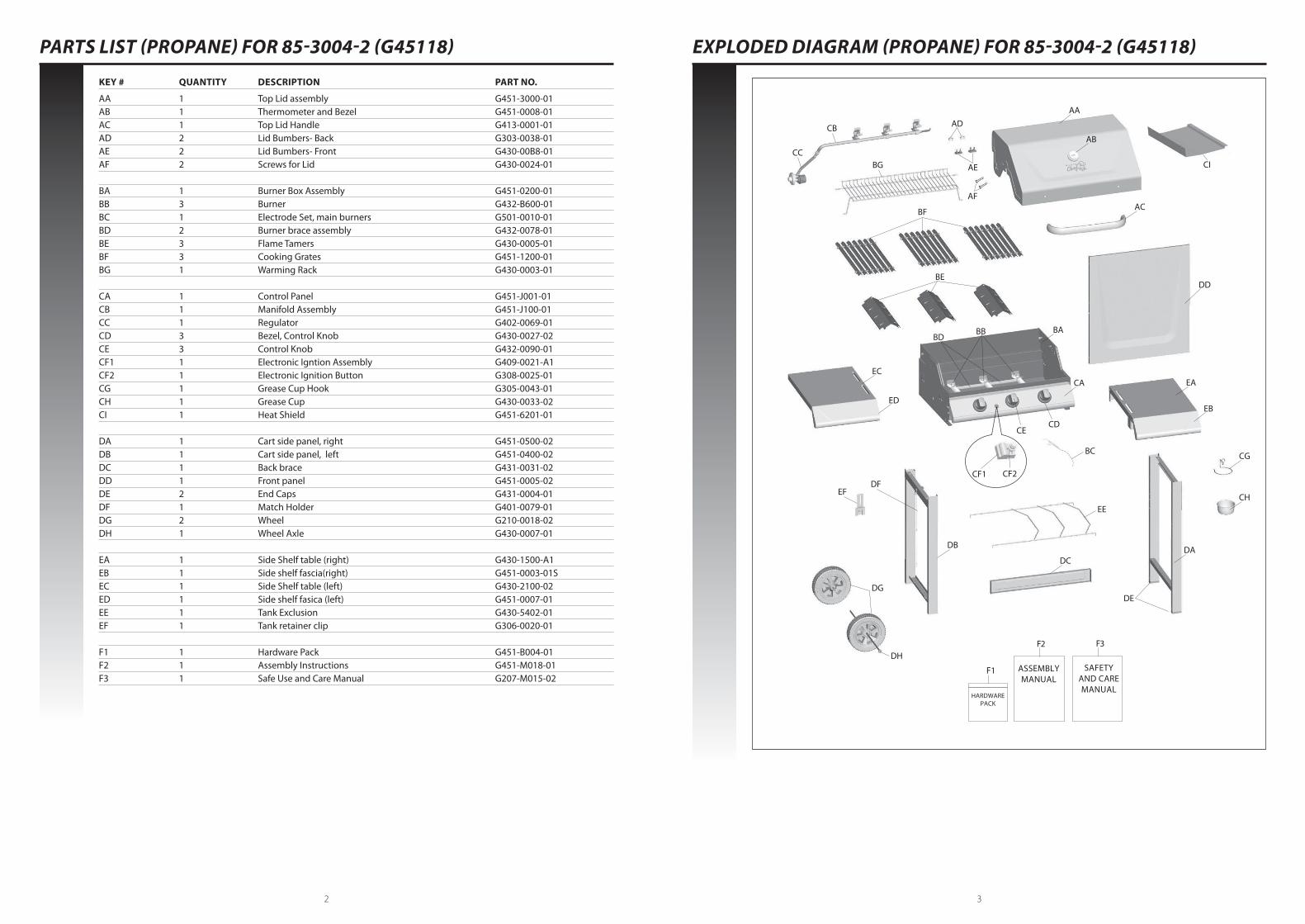
PARTS LIST (PROPANE) FOR 85-3004-2 (G45118) EXPLODED DIAGRAM (PROPANE) FOR 85-3004-2 (G45118)
KEY # QUANTITY DESCRIPTION PART NO.
AA 1 Top Lid assembly G451-3000-01 AB 1 Thermometer and Bezel G451-0008-01 AC 1 Top Lid Handle G413-0001-01 AD 2 Lid Bumbers- Back G303-0038-01 AE 2 Lid Bumbers- Front G430-00B8-01 AF 2 Screws for Lid G430-0024-01 BA 1 Burner Box Assembly G451-0200-01 BB 3 Burner G432-B600-01 BC 1 Electrode Set, main burners G501-0010-01 BD 2 Burner brace assembly G432-0078-01 BE 3 Flame Tamers G430-0005-01 BF 3 Cooking Grates G451-1200-01 BG 1 Warming Rack G430-0003-01 CA 1 Control Panel G451-J001-01 CB 1 Manifold Assembly G451-J100-01 CC 1 Regulator G402-0069-01 CD 3 Bezel, Control Knob G430-0027-02 CE 3 Control Knob G432-0090-01 CF1 1 Electronic Igntion Assembly G409-0021-A1 CF2 1 Electronic Ignition Button G308-0025-01 CG 1 Grease Cup Hook G305-0043-01 CH 1 Grease Cup G430-0033-02 CI 1 Heat Shield G451-6201-01 DA 1 Cart side panel, right G451-0500-02 DB 1 Cart side panel, left G451-0400-02 DC 1 Back brace G431-0031-02 DD 1 Front panel G451-0005-02 DE 2 End Caps G431-0004-01 DF 1 Match Holder G401-0079-01 DG 2 Wheel G210-0018-02 DH 1 Wheel Axle G430-0007-01 EA 1 Side Shelf table (right) G430-1500-A1 EB 1 Side shelf fascia(right) G451-0003-01S EC 1 Side Shelf table (left) G430-2100-02 ED 1 Side shelf fasica (left) G451-0007-01 EE 1 Tank Exclusion G430-5402-01 EF 1 Tank retainer clip G306-0020-01 F1 1 Hardware Pack G451-B004-01 F2 1 Assembly Instructions G451-M018-01 F3 1 Safe Use and Care Manual G207-M015-02
AA
CI
AB
AC
DD
EA
EB
CG
CH
DA
DE
DC
DB
EC
ED
DG
DH
DF
BG AE
ADCB
BC
CF1 CF2
CECD
EE
CA
BA
BE
BF
F2
F1 ASSEMBLYMANUAL
F3
SAFETYAND CAREMANUAL
HARDWAREPACK
CC
EF
AF
BBBD
4 5
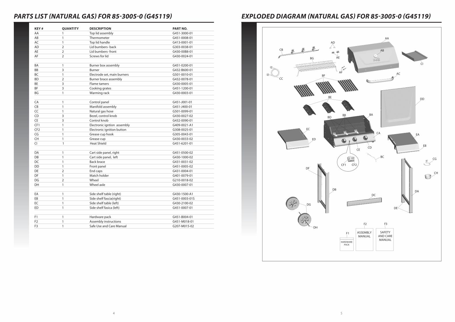
PARTS LIST (NATURAL GAS) FOR 85-3005-0 (G45119) EXPLODED DIAGRAM (NATURAL GAS) FOR 85-3005-0 (G45119)
KEY # QUANTITY DESCRIPTION PART NO. AA 1 Top lid assembly G451-3000-01 AB 1 Thermometer G451-0008-01 AC 1 Top lid handle G413-0001-01 AD 2 Lid bumbers- back G303-0038-01 AE 2 Lid bumbers- front G430-00B8-01 AF 2 Screws for lid G430-0024-01 BA 1 Burner box assembly G451-0200-01 BB 3 Burner G432-B600-01 BC 1 Electrode set, main burners G501-0010-01 BD 2 Burner brace assembly G432-0078-01 BE 3 Flame tamers G430-0005-01 BF 3 Cooking grates G451-1200-01 BG 1 Warming rack G430-0003-01 CA 1 Control panel G451-J001-01 CB 1 Manifold assembly G451-J400-01 CC 1 Natural gas hose G501-0099-01 CD 3 Bezel, control knob G430-0027-02 CE 3 Control knob G432-0090-01 CF1 1 Electronic igntion assembly G409-0021-A1 CF2 1 Electronic ignition button G308-0025-01 CG 1 Grease cup hook G305-0043-01 CH 1 Grease cup G430-0033-02 CI 1 Heat Shield G451-6201-01 DA 1 Cart side panel, right G451-0500-02 DB 1 Cart side panel, left G430-1000-02 DC 1 Back brace G431-0031-02 DD 1 Front panel G451-0005-02 DE 2 End caps G431-0004-01 DF 1 Match holder G401-0079-01 DG 2 Wheel G210-0018-02 DH 1 Wheel axle G430-0007-01 EA 1 Side shelf table (right) G430-1500-A1 EB 1 Side shelf fascia(right) G451-0003-01S EC 1 Side shelf table (left) G430-2100-02 ED 1 Side shelf fasica (left) G451-0007-01 F1 1 Hardware pack G451-B004-01 F2 1 Assembly instructions G451-M018-01 F3 1 Safe Use and Care Manual G207-M015-02
AA
CI
AB
AC
DD
EA
EB
CG
CH
DA
DE
DC
DB
EC
ED
DG
DH
DF
BG AE
AD
CB
CC
BC
CF1 CF2
CA
BA
BE
BF
F2
F1 ASSEMBLYMANUAL
F3
SAFETYAND CAREMANUAL
HARDWAREPACK
AF
BBBD
CECD
6 7
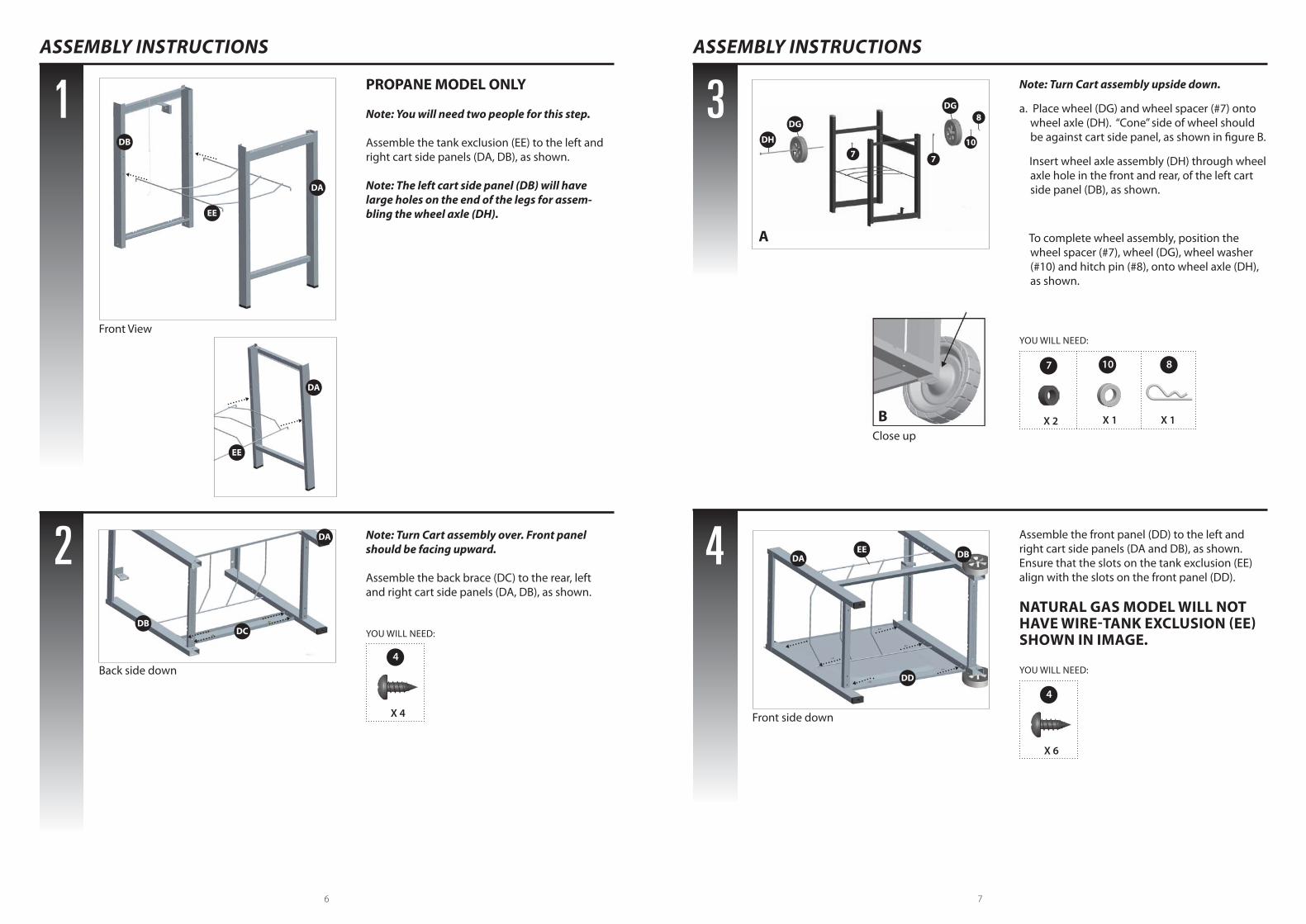
Note: Turn Cart assembly upside down.
a. Place wheel (DG) and wheel spacer (#7) onto wheel axle (DH). “Cone” side of wheel should be against cart side panel, as shown in figure B.
Insert wheel axle assembly (DH) through wheel axle hole in the front and rear, of the left cart side panel (DB), as shown.
To complete wheel assembly, position the wheel spacer (#7), wheel (DG), wheel washer (#10) and hitch pin (#8), onto wheel axle (DH), as shown.
PROPANE MODEL ONLY
Note: You will need two people for this step. Assemble the tank exclusion (EE) to the left and right cart side panels (DA, DB), as shown.
Note: The left cart side panel (DB) will have large holes on the end of the legs for assem-bling the wheel axle (DH).
Assemble the front panel (DD) to the left and right cart side panels (DA and DB), as shown. Ensure that the slots on the tank exclusion (EE) align with the slots on the front panel (DD).
NATURAL GAS MODEL WILL NOT HAVE WIRE-TANK EXCLUSION (EE) SHOWN IN IMAGE.
Note: Turn Cart assembly over. Front panel should be facing upward.
Assemble the back brace (DC) to the rear, left and right cart side panels (DA, DB), as shown.
1 3
2 4
ASSEMBLY INSTRUCTIONS ASSEMBLY INSTRUCTIONS
876
YOU WILL NEED:
YOU WILL NEED:
7
4
X 2
X 6
8
X 1
10
X 1
YOU WILL NEED:
4
X 4
DB
DA
EE
EE
DA
DAEE DB
DD
DA
DBDC
DG
DG
DH
Front View
Back side down
Front side down
Close up
7 7
10
8
B
A
8 9
5
6
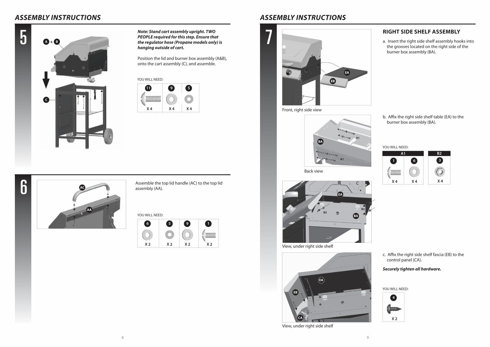
Note: Stand cart assembly upright. TWO PEOPLE required for this step. Ensure that the regulator hose (Propane models only) is hanging outside of cart.
Position the lid and burner box assembly (A&B), onto the cart assembly (C), and assemble.
YOU WILL NEED:
YOU WILL NEED:
ASSEMBLY INSTRUCTIONS ASSEMBLY INSTRUCTIONS
7 RIGHT SIDE SHELF ASSEMBLY
a. Insert the right side shelf assembly hooks into the grooves located on the right side of the burner box assembly (BA).
b. Affix the right side shelf table (EA) to the burner box assembly (BA).
c. Affix the right side shelf fascia (EB) to the control panel (CA).
Securely tighten all hardware.
Assemble the top lid handle (AC) to the top lid assembly (AA).
11
X 4
1
X 2
5
X 4
5
X 2
6
X 2
9
X 4
9
X 2
YOU WILL NEED:
1 36
X 4 X 4X 4
YOU WILL NEED:
4
X 2
AC
AA
EA
EB
A B+
C
EB
CA
EA
View, under right side shelf
View, under right side shelf
Front, right side view
Back view
A1 B2
A1
A1
BA
BAB2
B2
EA
10 11
ASSEMBLY INSTRUCTIONS
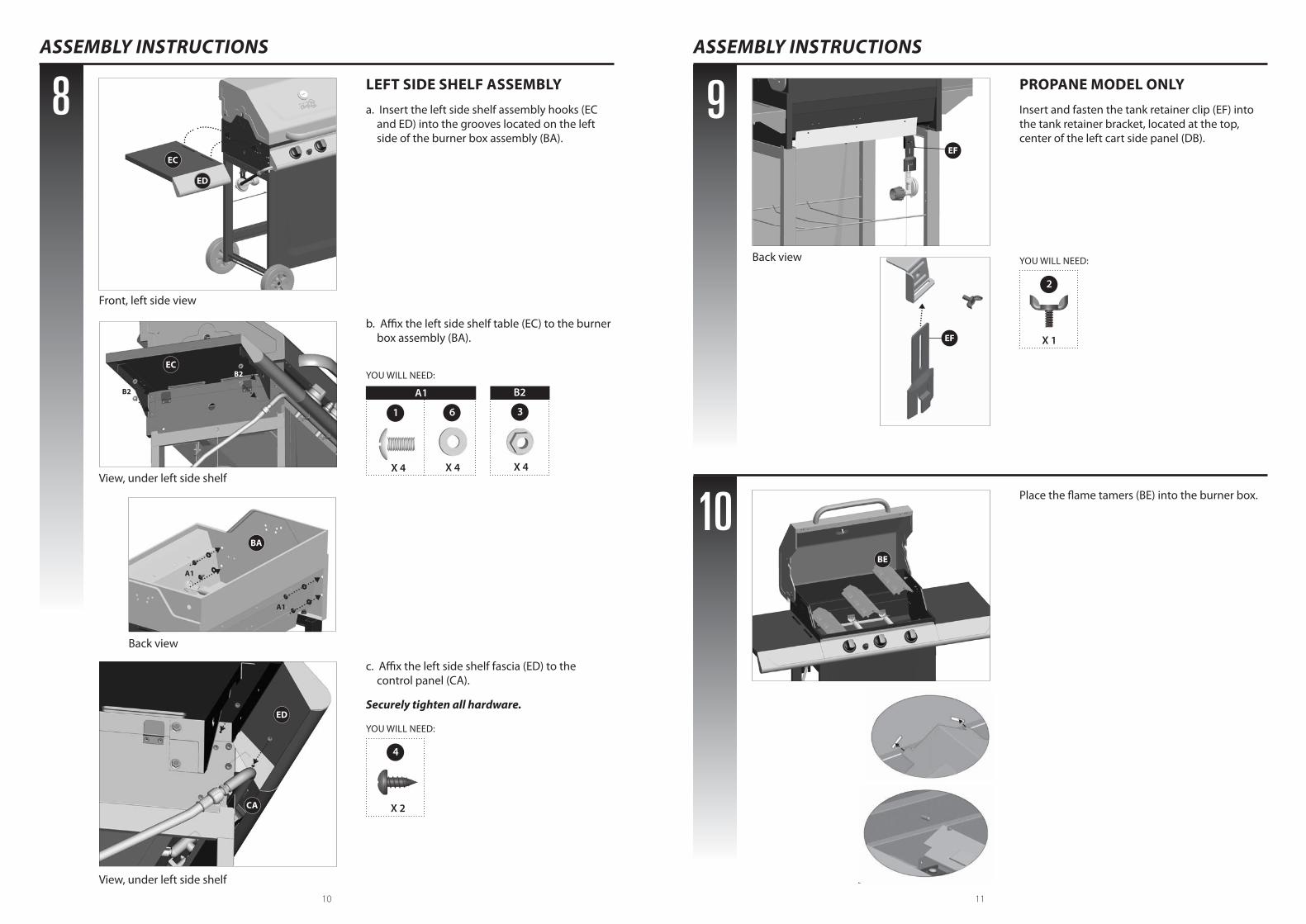
8 LEFT SIDE SHELF ASSEMBLY
a. Insert the left side shelf assembly hooks (EC and ED) into the grooves located on the left side of the burner box assembly (BA).
b. Affix the left side shelf table (EC) to the burner box assembly (BA).
c. Affix the left side shelf fascia (ED) to the control panel (CA).
Securely tighten all hardware.
YOU WILL NEED:
4
X 2
YOU WILL NEED:
1 36
X 4 X 4X 4
BA
PROPANE MODEL ONLY
Insert and fasten the tank retainer clip (EF) into the tank retainer bracket, located at the top, center of the left cart side panel (DB).
Place the flame tamers (BE) into the burner box.
ASSEMBLY INSTRUCTIONS
9
10
YOU WILL NEED:
2
X 1
BE
EF
EF
ED
CA
Back view
Front, left side view
View, under left side shelf
View, under left side shelf
Back view
A1 B2
A1
A1
EC
B2
B2
EC
ED
12 13
ASSEMBLY INSTRUCTIONS
11
12
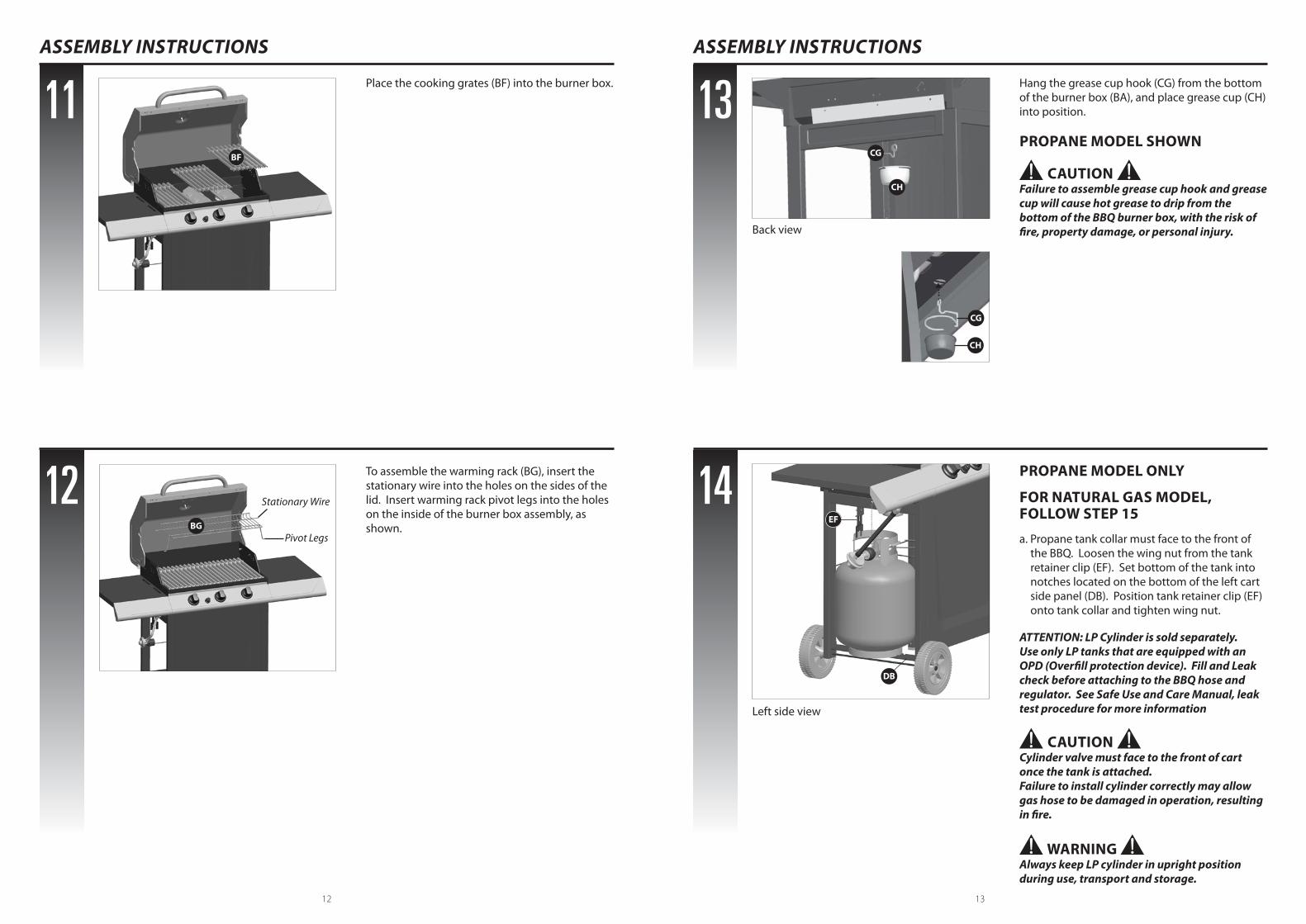
Place the cooking grates (BF) into the burner box.
To assemble the warming rack (BG), insert the stationary wire into the holes on the sides of the lid. Insert warming rack pivot legs into the holes on the inside of the burner box assembly, as shown.
BF
BG
Stationary Wire
Pivot Legs
ASSEMBLY INSTRUCTIONS
13
14
Hang the grease cup hook (CG) from the bottom of the burner box (BA), and place grease cup (CH) into position.
PROPANE MODEL SHOWN
CAUTION Failure to assemble grease cup hook and grease cup will cause hot grease to drip from the bottom of the BBQ burner box, with the risk of fire, property damage, or personal injury.
CAUTION Cylinder valve must face to the front of cart once the tank is attached. Failure to install cylinder correctly may allow gas hose to be damaged in operation, resulting in fire.
PROPANE MODEL ONLY
FOR NATURAL GAS MODEL, FOLLOW STEP 15
a. Propane tank collar must face to the front of the BBQ. Loosen the wing nut from the tank retainer clip (EF). Set bottom of the tank into notches located on the bottom of the left cart side panel (DB). Position tank retainer clip (EF) onto tank collar and tighten wing nut.
WARNING Always keep LP cylinder in upright position during use, transport and storage.
ATTENTION: LP Cylinder is sold separately. Use only LP tanks that are equipped with an OPD (Overfill protection device). Fill and Leak check before attaching to the BBQ hose and regulator. See Safe Use and Care Manual, leak test procedure for more information
CG
CH
EF
DB
Left side view
Back view
CG
CH

14
ASSEMBLY INSTRUCTIONS
15
16 Electronic ignition battery not included.
Unscrew the electronic ignition button (CF2) and insert one AA battery into the electronic ignition battery compartment (CF1), with the positive end facing outward.
NATURAL GAS MODELS ONLY
Attach the natural gas hose (CC) to the manifold (CB), as shown.
ATTENTION: In order to complete installation of your natural gas BBQ a 1/2” or 3/8” adapter may be required to connect your BBQ’s natural gas hose to your home gas supply. Contact your natural gas supplier to purchase the necessary part.
CC
CB
CF2
Left side view
+-