t2 i -...
TRANSCRIPT

CHAPTER 12 Pilot Operated Pressure
Control Valves
Unlike a simple or direct operated pressure control valve, where a spool is held biased by spring pressure only, a pilot operated valve has its spool biased by both fluid and spring pressure. This combination eliminates the high override commonly found in direct operated pressure valves.
override characteristic of direct operated valves
A pressure valve's override characteristic may be best described by an example:
The graph shows the functioning of a direct operated relief valve operating in a typical system. The valve is required to relieve a system flow of 1 a gpm (37.9 Ipm) at 1000 psi (68.97 bar) . In order to perform this function , the valve begins to open or "crack" at a lower pressure. This causes a small portion of system flow to return to tank. As pressure increases, the spool spring is continuously compressed in orderto form a larger opening for the increasing flow returning to tank. Finally at 1000 psi (68.97 bar), a total flow of 10 gpm (37.9 Ipm) passes through the valve. If for some reason system flow is increased, pressure will rise above or "override" the 1000 psi (68.97 bar) level. A direct operating valve acts in this manner because of compression of the spool spring.
override characteristic of pilot operated valves
A pilot operated relief valve avoids an early cracking pressure and severe override by eliminating the heavy spool spring. Fluid pressure and a light spring bias the valve spool. When a certain system pressure is reached , the spool is actuated. Any slight override which results with increased flow is primarily due to the compression ofthe light spring. To understand the operation of a pilot operated pressure control valve, initially, we will concentrate on the operation of a pilot operated relief valve.
what a pilot operated relief valve consists of
A pilot operated relief valve consists of two valves - a main valve and a pilot valve. The main valve is made up of a body with inlet and outlet ports, a
(ij 3000 psi :: 206.9 bar '0 a. ~ 2000 psi :; 137.9 bar l!l ~ a.. 1000 psi
68.97 bar
(ij 3000 psi :: 206.9 bar '0 a. ~ 2000 psi :> 137.9 bar rn rn ~
Direct Operated Relief Valve Override
---___ - Relieving pressure
5 gpm 10 gpm 15 gpm 20 gpm 18.951pm 37.91pm 56.851pm 75.81pm
Cracking pressure
Flow - gpm / Ipm
Pilot Operated Relief Valve Override
a.. 1000 psi .,..,-=_:..:_:..:_:..:_:...:_:...:_=_=---_-•• ~~-.....,-;:-;-:-:-=-=---= __ 68. 97 bar _______ RelieVing
~ Spring
Oril ..
Inlet ~cm
SyelOm
Outlot" Tank
pressure
5 gpm 10 gpm 15 gpm 20 gpm 18.951pm 37.91pm 56.851pm 75.8 1pm
Flow - gpm / Ipm
S<r_ Adjuomont
~~~ I $ 1_- I I
t2_ il PioC Oper. led
Relet Valve Symbol
12-1

12-2
25 PSI
Main Valve
Outlet to Tank
Pilot Valve
P~'"~EI : ::~
975 PSI
975 PSI Spring
To Tank
To Tank
spool with an orifice, and a spool bias spring. The pilot valve consists of a dart, dart bias spring, and screw adjustment.
how a pilot operated relief valve works
To understand the operation of a pilot operated relief valve, we will look at the independent operation of the main valve and the pilot valve. The main valve spool is biased by a light spring. The stem of the main valve spool plugs the outlet to tank. System pressure acts on the area under the spool skirt. Any leakage past the spool is internally drained back to tank through a passage in the valve body.
If the spring biasing the main valve spool has a value of 25 psi (1.7 bar), the spool will be pushed up and system flow will pass to tank when system pressure reaches 25 psi (1 .7 bar) . In this way, the valve functions as any of the spring biased pressure control valves which we have seen up to this time.
The movable part of the pilot valve is a dart. The area of the dart exposed to hydraulic pressure is relatively small. The spring which biases the dart on its seat is rather stiff. The combination of small area and stiff spring means that the dart will remain seated until a high pressure is reached.
If the spring biasing the dart has a value of 975 psi (67.2 bar), the dart will remain seated until this pressure is reached. At this time, the dart will unseat and flow will pass to tank. Consequently, pressure is limited to 975 psi (67.2 bar). In this manner, the pilot valve also acts like any of the spring biased pressure control valves we have seen previously.
The pilot valve is a simple, spring-biased pressure control which handles small flows at high pressures. The main valve is also a simple, springbiased pressure control which handles larger flows at low pressure. By using the two together, large flows can be handled at high pressures without the consequence of an early cracking pressure or severe override.
In a pilot operated relief valve, the main valve spool is biased by light spring pressure and fluid (pilot) pressure in the spring chamber. The maximum fluid pressure which is allowed to bias the spool is determined by the setting of the pilot valve.

To I allow pressure to accumulate in the spring chamber, an orifice or hole is drilled through the main valve spool skirt.
I
To illustrate the operation of a pilot operated relief valve, assume that the spring biasing the main valve spool has a value of 25 psi (1 .7 bar) and that the pilot valve will limit the pilot pressure in the spring chamber to 975 psi (67.2 bar).
With a system pressure of 800 psi (55.17 bar) , 800 psi (55.17 bar) is acting to push the spool up. 800 psi (55.17 bar) is transmitted through the orifice to the spring chamber and acts to hold the spool l::lown. The areas exposed to pressure on either Side of the spool skirt are equal. Therefore, the spool is balanced except for the 25 psi (1.7 bar) spring. Consequently, there is a hydraulic pressure of 800 psi (55.17 bar) trying to unseat the spool and a total hydraulic and mechanical pressure of 825 psi (56.89 bar) keeping the spool seated.
With a system pressure of 900 psi (62.1 bar) , 900 psi (62.1 bar) at the bottom of the spool acts to push the spool up. A total mechanical and hydraulic pressure of 925 psi (63.79 bar) acts to keep the spool down.
When system pressure rises to 990 psi (68.28 bar) , 990 psi (68.28 bar) will act to push the spool up. Since the pilot valve is set to limit the fluid pressure inthe spring chamber to 975 psi (67.2 bar), the pilot valve dart is unseated and the pilot pressure above the spool is 975 psi (67.2 bar) . This is a total hydraulic and mechanical pressure of 1000 psi (68.97 bar) acting to hold the spool down. The total pressure acting down is still more than the pressure acting up. The maximum pressure which can bias the spool in the down position is 1000 psi (68.97 bar) . If pressure below the spool attempts to rise above 1000 psi (68.97 bar) , the spool will be pushed up and flow will pass to tank .
In our example, up to a pressure of 975 psi (67.2 bar), the total mechanical and fluid pressure biasing the spool will be 25 psi (1.7 bar) greater than system pressure. Between 975 psi (67.2 bar) and 1000 psi (68.97 bar) , the difference becomes less until at any pressure over 1000 psi (68.97 bar) the main valve spool is unseated.
other pilot operated pressure control valves
In addition to relief valves, sequence, counterbalance, unloading, and pressure reducing valves
In
Out
Dart set to unseat at 975 psi / 67.2 bar
~--;;::::===;:::::::;-J
Orifice
1000 psi 68.97 bar
975 psi 67.2 bar
990PSi~ 88 .28 bar
Pilot Dart Unseated
Va lve Relieving
Pilot Oper. ted
-.-Pilot Operated, CounlMb.~n::e
V .... ....... h Remote PiG! (Cfled,: Vatve Not~)
L...-___ ---' ~nce v."",
(01ed< VlIl ... Not Shown)
12-3

1000 psi
drain ...------,
Pilot operated pressure reducing valve
Remote pilot valve
Example Pilot Operated Relief Valve
Performance Curve
ro .D
68.92 ba r J:':'-:-.:-~-:..:-:.:-~-:.:.-;.-;-~-~-:.:-:.-:.:.-.:-..:-:.::-~--~-900 psi - 62 bar
.~ , ~ => 500 psi :z 34.45 bar ~ 0.
12-4
5 gpm 18.951pm
Flow - gpm {Ipm
Dart Wears
10 gpm 37.91pm
can also be pilot operated. Just as relief valves, the other pilot operated pressure controls consists of a pilot valve and main valve spool. The spools in these valves are different from a relief valve spool, but pilot pressure is still sensed through a passage in the main valve spool.
remote pilot adjustment
Since fluid pressure is used to bias the main valve spool, a pilot operated pressure control valve can be adapted for remote adjustment. With an additional pilot valve connected to the spring chamber of a pilot operated valve, the maximum pressure in the spring chamber of the main spool will be limited to the setting of the remote pilot valve if that setting is lower than the other pilot valve. With this arrangement, the remote pilot valve can be mounted on a panel for ease in adjustment by a machine operator.
In the illustration of remote adjustment, a remote pilot valve is used in conjunction with a pilot operated relief valve. This is a very common application. Pilot operated unloading, counterbalance, sequence and pressure reducing valves can also be remotely adjusted.
cracking pressure - pilot operated relief valve
Since the main spring of a pilot operated relief valve is relatively light, the valve cracking pressure is closer to full flow pressure than in a simple relief valve.
The illustrated performance curve for a pilot operated relief valve pOints out that the valve cracks open and reaches full flow within 100 psi (6.89 bar) of its maximum pressure setting of 1 000 psi (68.92 bar). Whereas, with the simple relief valve seen earlier, the valve cracked open and reached full flow within 200 psi (13.8 bar) while handling the same flow.
operating problems with a pilot operated relief valve
Certain problems can arise while using a pilot operated relief valve. Many problems can be traced to dart wear, orifice plugging, and excessive line lengths between remote and main pilot valves.
As a pilot operated relief valve operates, the dart in the pilot valve can wear as it moves on and off its seat. This causes leakage from the main spring

chamber back to tank. If wear, and consequently leakage become excessive, sufficient pilot pressure above the spool skirt will not be maintained. As a result, valve and system will become erratic.
In cases where systems are not properly protected with filters, dirt can plug the orifice in the spool. This means pressure can no longer pass to the pilot-spring chamber on top of the spool. When this occurs, the valve will actuate one time. The spool will not close or will close very slowly since fluid pressure has a difficult time transmitting through the orifice.
In some instances, a problem occurs where excessive line lengths exist between main valve and a remote pilot adjustment. It appears that the farther a remote pilot valve is removed from its main valve, the more chance of pressure pulsations, fluid compressibility, and valve springs interacting to generate irritable noises and excessive vibration. For this reason, it is usually recommended that line lengths be kept to a minimum.
adjusting a relief valve
With pressure gage positioned close to pump outlet or plugged into the relief valve body, and with reservoir fluid at its operating temperature, a system relief valve can be adjusted.
With the relief valve set sufficiently high so that no flow passes through the valve, the gage will indicate the amount of pressure the pump/electric motor must develop to overcome resistances of load and liquid as the system is doing useful work. This is pump/electric motor working pressure.
A relief valve should be adjusted so that the valve cracking pressure is above pump/electric motor working pressure. Valve cracking pressure can be determined from a manufacturer's catalog.
Adjusting a simple relief valve may mean the valve is set 200 psi (13.8 bar) over working pressure. This causes no harm or system inefficiency when the system is doing work. But, once the system becomes solid, pump pressure will have to climb 200 psi (13.8 bar) before the valve will accept its full flow.
With a pilot operated relief valve in the same circuit, the valve could be set at a lower pressure; its cracking to full flow range is less than a simple relief valve. Full pump flow could then pass through the valve at perhaps 100 psi (6.89 bar) over working pressure. This generates less heat.
Dirt Plugging Orifice
1000 psi
Keep to a Minimum Distance
p----1 1 1 1
1-
Simple Relief Valve Setting at 1000 psi 168.92 bar
68.92 bar J~-~-=-~-~-~-~-~-~-~-~-~-~-:':-:":-~-:'-:':'-':-~---""'l"-m .0 800 psi 'iii 55.1 bar a. , 500 psi ~ ~ 34.45 bar <J) <J)
~ c.. Working Pressure
Less Than 800 psi 1 55.1 bar
5gpm 18.951pm
Flow - gpm Ilpm
10gpm 37.91pm
12-5

Pressure Pilot Operated Relief psi / bar Valve Setting @
900 psi / 62 bar
1000 psi/68.92 bar 900 psi/62 bar - - - - - - - - - - - - - - - - - - - -
800 psi/55.12 bar
500 psi/34.45 bar
12-6
Working pressure less than 800 psi / 55.12 bar
5 gpm 10 gpm 18.951pm 37.91pm
Flow - gpm /Ipm
,- -, ,
L.!.J
Valve Vented
Using 100 psi (6.89 bar) less each time the relief valve is actuated does not seem like much, but with a flow rate of 10 gpm (37.9Ipm) this saves.6 HP (447.6 watts). With 25 gpm (94.75 Ipm), it saves 1.5 HP (1119 watts). And, with 50 gpm (189.5Ipm), 2.9 HP (2163.4 watts) is saved.
Dumping flow over a relief valve is only designed to occur for a short period of time. If actuators are stalled for anything above a few seconds, the pump/electric motor should be unloaded. In the following sections, we learn what high and low vent are and we see that unloading a pump doesn't necessarily mean the electric motor is unloaded.
pump unloading
During idle time, when actuators are stalled, flow should not be dumped over a relief valve for anything more than a few seconds. Relief valves are designed to be used for short periods of time. If this rule is not followed, considerable heat will be added to the system unnecessarily.
Anytime actuators are stalled for an extended period, horsepower generation by pump/electric motor should be as close as possible to zero. In some instances, this is accomplished by shutting off the electric motor, but in most cases this is impractical.
A common way of reducing power generation by pump/electric motor is unloading pump flow back to tank through a valve. Unloading pump flow drops discharge pressure and consequently power generation .
unloading through a pilot operated relief valve
A common way of unloading pump flow during idle time is "venting ."
Venting a relief valve refers to releasing the fluid pressure biasing the main spool of a pilot operated relief valve. By releasing this pilot pressure, the only pressure holding the spool closed is the relatively light pressure of the spring. This results in the pump applying a relatively low pressure to return its flow to tank.
In the circuit illustrated, a solenoid operated directional valve is connected to the vent line of a pilot operated relief valve. With the solenoid de-energized, maximum pump pressure is determined by the relief valve setting. When the solenoid is energized during idle time, pump flow returns to
tank at whatever pressure it takes to overcome the relatively light spring biasing the spool.
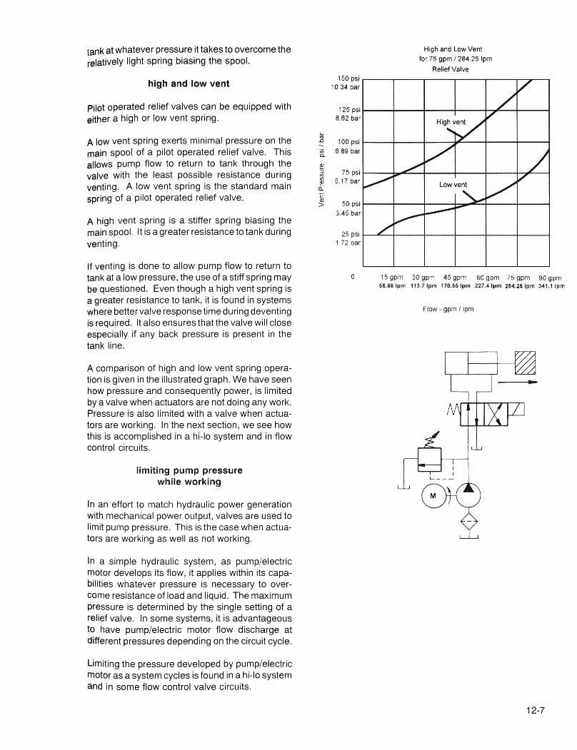
high and low vent
Pilot operated relief valves can be equipped with either a high or low vent spring.
A low vent spring exerts minimal pressure on the main spool of a pilot operated relief valve. This allows pump flow to return to tank through the valve with the least possible resistance during venting. A low vent spring is the standard main spring of a pilot operated relief valve .
A high vent spring is a stiffer spring biasing the main spool. It is a greater resistance to tank during venting .
If venting is done to allow pump flow to return to tank at a low pressure, the use of a stiff spring may be questioned. Even though a high vent spring is a greater resistance to tank, it is found in systems where better valve response time during deventing is required. It also ensures that the valve will close especially if any back pressure is present in the tank line.
A comparison of high and low vent spring operation is given in the illustrated graph. We have seen how pressure and consequently power, is limited by a valve when actuators are not doing any work. Pressure is also limited with a valve when actuators are working. In the next section, we see how this is accomplished in a hi-Io system and in flow control circuits.
limiting pump pressure while working
In an effort to match hydraulic power generation with mechanical power output, valves are used to limit pump pressure. This is the case when actuators are working as well as not working.
In a simple hydraulic system, as pump/electric motor develops its flow, it applies within its capabilities whatever pressure is necessary to overcome resistance of load and liquid. The maximum pressure is determined by the single setting of a relief valve. In some systems, it is advantageous to have pump/electric motor flow discharge at different pressures depending on the circuit cycle.
Limiting the pressure developed by pump/electric motor as a system cycles is found in a hi-Io system and in some flow control valve circuits .
~ .D -'in a.
!!! :0
'" '" !!! Q.
C Q)
>
150 psi 10.34 bar
125 psi 8.62 bar
100 psi 6.89 bar
75 psi 5.1 7 bar
50 psi 3.45 bar
25 psi 1.72 bar
o
High and Low Vent for 75 gpm I 284 .25 Ipm
Relief Valve
15 gpm 30 gpm 45 gpm 60 gpm 75 gpm 90 gpm 56 .851pm 113.71pm 170.551pm 227 .41pm 284.25Ipm 341 .11pm
Flow - gpm I lpm
12-7

500 psi 345 bar 50 gpm t
189.51pm
t t
~ Limit U switch
Hi-La System
1500 psi 103.4 bar
5 gpm ~ ___ .! 18.951pm
Due to now control 4 5 gpm -------- valve setting t 17 05 Ipm
45 gpm 107 .6 1pm
rr--I+-i=:::::::r::~
, - - --
12-8
hl-Io system
A hi-Ia system consists of two pumps - one high volume, the other low volume. Both pump flows combine under low pressure to give a large rate of flow. Yet, when system pressure climbs above a certain value, the high volume pump is unloaded while the low volume pump does the work.
In the illustrated hi-Io system, the cylinder is not required to work through its entire stroke. Work is performed through the last few inches of stroke only .
A flow rate of 4.5 gpm (17 .051/min) flowing into the cylinder is required while the cylinder is dOing its work. Yet, to reduce the amount of time getting to and from the work, 50 gpm (189.51/min) is desired. If a 50 gpm (189.5 I/min) pump were used in this system, 45 gpm (170.6 I/min) would dump back to tank over the relief valve while work is performed. This would be a gross mismatch of power generated to power used .
A hi-Io system satisfies the system demand by combining a 45 gpm (170.6 IImin) and 5 gpm (18.95 I/min) pump flow. When the electric motor is turned on, the 45 gpm (170.6 I/min) passes through the check valve adding tothe 5 gpm (18.95 IImin) flow; 50 gpm (189.5 I/min) passes out into the system extending the cylinder at a relatively low pressure. When the work load is contacted and work pressure is desired, pump/electric motor pressure starts climbing toward the relief valve setting of 1500 psi (103.4 bar) . As it passes through the 500 psi (34.5 bar) pressure level , the normally non-passing unloading valve opens allowing the 45 gpm (170.6 I/min) pump to unload while the 5 gpm (18.95 I/min) pump continues to work. This action eliminates unnecessary power generation by the 45 gpm (170.6 1/min) pump when it is not needed.
After work has been completed , the directional valve is shifted to retract the cylinder and pressure drops to a low level once again. This closes the unloading valve . The 45 gpm (170.6 1/min) adds to the 5 gpm (18.95 IImin) retracting the cylinder quickly.
A hi-Io system gives high volume at low pressure and low volume at high pressure. In this way, power generation is more evenly matched to actuator output.
A hi-Io system is one means of limiting pump pressure by a valve when a system is working. In the next section, we shall see how maximum pump
pressure can be controlled in a flow control circuit by, a solenoid operated relief valve.
flow control circuit
IJ. flow control valve is a restriction. If it is used in a meter-in or meter-out application , pump/electric motor attempts to overcome the restriction by applying a higher pressure. This actuates the relief valve . The desired flow goes through the flow control ; excess flow dumps over the relief valve .
As far as a pump/electric motor is concerned, with a meter-in or meter-out circuit , flow is discharged at the relief valve setting even though the load requires much less pressure. Pump/electric motor generate more power than required ; and, the excess turns into heat.
Excess power generation is a common occurrence with flow control circuits . Flow control valves are not the most efficient means of reducing pump flow, but they are many times very accurate and economical. Once again , the best that can be hoped for when metering-in or metering-out is to match as close as practical power generated with actuator output.
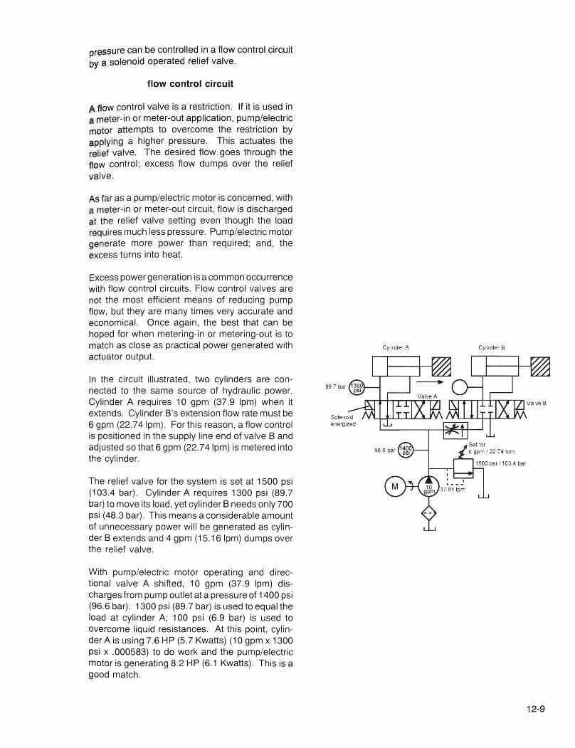
In the circuit illustrated , two cylinders are connected to the same source of hydraulic power. Cylinder A requires 10 gpm (37.9 Ipm) when it extends. Cylinder 8 's extension flow rate must be 6 gpm (22.74Ipm). For this reason , a flow control is positioned in the supply line end of valve 8 and adjusted so that 6 gpm (22.74Ipm) is metered into the cylinder.
The relief valve for the system is set at 1500 psi (103.4 bar). Cylinder A requires 1300 psi (89.7 bar) to move its load, yet cylinder 8 needs only 700 psi (48 .3 bar) . This means a considerable amount of unnecessary power will be generated as cylinder 8 extends and 4 gpm (15.16 Ipm) dumps over the relief valve .
With pump/electric motor operating and directional valve A shifted , 10 gpm (37.9 Ipm) discharges from pump outlet at a pressure of 1400 psi (96.6 bar). 1300 psi (89.7 bar) is used to equal the load at cylinder A; 100 psi (6.9 bar) is used to overcome liquid resistances. At this point, cylinder A is using 7.6 HP (5 .7 Kwatts) (10 gpm x 1300 psi x .000583) to do work and the pump/electric motor is generating 8.2 HP (6.1 Kwatts) . This is a good match.
Cyl inder A Cylinder B
12-9

900 psi 62.1 bar
12-10
Cylinder A
1500 psi 103.4 bar
Cylinder B
900 psi 62.1 bar
1500 psi 103.4 bar
After cylinder A has performed its work, directional valve A is de-energized and directional valve B is shifted. With the pressure compensated flow control valve set for 6 gpm (22.74 Ipm), pump/ electric motor cannot discharge its 10 gpm (37.9 Ipm) flow into cylinder B causing pressure at the pump outlet to rise to 1500 psi (103.4 bar) even though cylinder B only requires 700 psi (48.3 bar) . At 1500 psi (103.4 bar) , the relief valve is actuated and allows the excess volume of 4 gpm (15.2 Ipm) to return to tank. At this point, pump/electric motor is generating 8.7 HP (6.5 Kwatts) (10 gpm x 1500 psi x .000583) ; cylinder B is using only 2.4 HP (1.8 Kwatts) (6 gpm x 700 psi x .000583) . This is a gross mismatch, 4.9 HP (3 .2 Kwatts) is turned into heat.
To more closely match input and output power, the system described can be equipped with a solenoid operated relief valve which automatically lowers its setting when cylinder B is working .
solenoid operated relief valve
In the description of a pilot operated relief valve, it was indicated that the pilot valve setting determined at which point the valve would limit pump pressure. It was also shown that a remote pilot valve connected to the main spool spring chamber would control relief valve operation as long as its setting were lower than the main pilot valve. A solenoid operated relief valve takes advantage of this arrangement.
what a solenoid operated relief valve consists of
A solenoid operated rel ief valve consists of a pilot operated relief valve, directional valve, and remote pilot valve. The directional valve is mounted on top of the relief valve body. The remote pilot valve can be mounted on a fixture or panel near the main valve.
how a solenoid operated relief valve works
A solenoid operated relief valve changes setting as the directional valve mounted on top of its housing is shifted.
In the illustration, a remote pilot valve is connected to a pilot operated relief valve. With the remote valve set for 900 psi (62.1 bar) and the main pilot valve adjusted to 1500 psi (103.4 bar) , the remote pilot valve controls the relief valve operation. However, if the remote valve were disconnected,

ttie main pilot valve would determine relief pres~ure. The action of connecting and disconnecting the remote pilot valve in a solenoid operated relief
alve is performed by the directional valve.
solenoid operated relief valve in a circuit
With a solenoid operated relief valve in our twocylinder circuit, power generation can be more evenly matched when cylinder B is working .
The main pilot valve is set to limit pump/electric motor pressure to 1500 psi (103.4 bar) ; the remote pilot valve is set for 900 psi (62.1 bar).
When cylinder A is working , electric circuitry controlling the solenoid operated relief valve is arranged so that its directional valve is de-energized. Maximum pump pressure is limited to 1500 psi (103.4 bar) . Pump/electric motor discharges 10 gpm at 1400 psi (96.6 bar) . Cylinder A uses 7.6 HP (5.7 Kwatts) and pump/electric motor generates 8.2 HP (6.1 Kwatts) .
When cylinder B is working , the directional valve of the solenoid operated relief valve is energized . This action causes the remote pilot valve and main valve to connect limiting pump/electric motor pressure to 900 psi (62.1 bar). At this point, 5.3 (3 .9 Kwatts) hydraulic horsepower is being generated and 4.1 HP (3.0 Kwatts) is used by cylinder B. This is a closer match than if the relief valve setting were kept at 1500 psi (103.4 bar).
In the circuit just described , the solenoid actuated, spring offset valve connected and disconnected a remote pilot valve to the main spring chamber of a pilot operated relief valve. If the remote pilot port of the valve were connected to tank instead of to a remote pilot valve , the relief valve would be vented when the directional valve was shifted . This is commonly done.
Solenoid operated relief valves are frequently equipped with 3-position directional valves. This allows three different relief valve settings - one for each directional valve position.
Referring to our two cylinder circuits once again , the illustration shows that the solenoid operated relief valve now has a directional valve with three positions. The directional valve has a tandem center.
Electrical circuitry is arranged so that when cylinder A is working , the directional valve is not
62.1 bar
6 gpm 22.7 Ipm
6 gpm 22.71pm
Remote va~ve actuated 900 psi
62.1 bar ." - -, II I
Solenoid I I I I
energized I .. - - - w
12-11

Cylinder A
Cylinder A
12-12
Cylinder B
Set tor 6 gpm 22.74 1pm 6~~~ p~~r
IT --'I II I
II I I I ~ - - - I I l.LJ
@TI~N~d'~ 1103.4 bar ;- _. : center
L.U
Cylinder B
detfor69gP 200 psi 22.74 1pm 900 psi 13.8 bar 62.1 bar
,-- TI IT --, I I I I I I I I I I II I I I ___ •• Ik___ I
l.LJ I I l.LJ
~T
»J r IIfflX ~ 1500 psi I I Tandem
1103.4 bar ;- _. : center
L.U
connecting the main relief spring chamber with anything. Maximum pump/electric motor pressure is therefore limited to 1500 psi (103.4 bar) .
When cylinder B works, the relief directional valve joins remote pilot valve to spring chamber limiting pump/electric motor pressure to 900 psi (62.1 bar).
When work is completed, the directional valve is centered connecting main spring chamber to tank. The relief valve vents unloading the pump.
If the relief directional valve were equipped with a closed center, three maximum working pressures could be selected.
Referring to our two cylinder circuit, assume that both cylinders retract separately and that the flow rate entering the rod side of cylinder B is required to be no more than 6 gpm (22.74 Ipm). With flow control adjusted to meter 6 gpm (22.74 Ipm) into the cylinder, excess pump flow would have to be dumped over the relief valve at the relatively high setting of 900 psi (62.1 bar) when retract pressure is 50 psi (3.4 bar). This generates unnecessary power and heat.
Incorporating another remote pilot valve adjusted for 200 psi (13.8 bar) , the relief directional valve could connect main spring chamber with th is low pressure setting during cylinder B retraction . Power generation could then more evenly be matched with actuator output during this portion ofthe cycle.
We saw that as pump flow was unloaded to tank through various valves, the generated power at pump outlet dropped to a low level. However, this does not mean that the electric motor coupled to the pump is completely unloaded. Pump overall efficiency must be considered.
overall pump efficiency
To reduce the amount of power and heat generated by a pump/electric motor when it is not requiredto do work, pump flow should be directed to tank at a low pressure. As has been illustrated, this can be accomplished through the center position of a directional valve, an unloading valve of a hi-Io system, or by venting a pilot operated relief valve .
When pump flow is unloaded to tank, pressure and therefore generated hydraulic power, drop to a very low level. However, it should not be thought that the electric motor no longer has to work. A pump's overall efficiency has to be considered.

Overall efficiency takes into account a pump's mechanical efficiency as well as its volumetric efficiency. Pump overall efficiency can be determined by dividing hydraulic horsepower delivered to the system by the input horsepower of the electric motor.
An expression which describes overall efficiency is:
Overall efficiency = Hydraulic HP Output x 100 (%) Input HP of EI. Mtr.
If a particular pump/electric motor delivered 10 gpm (37.9Ipm) to a system at 1000 psi (68.97 bar) , this would be 5.8 HP (4 .3 Kwatts) (10 gpm x 1000 psi x .000583) . If the electric motor driving the pump hadto develop 7 HP (5 .2 Kwatts) , then pump overall efficiency would be 83% .
Industrial hydraulic pumps are generally designed to be operated at pressures above 200-400 psi (13.8-27.5 bar) . Consequently, the overall efficiency of a pump is greatly diminished below this low pressure range .
An electric motor developing 7 HP (5 .2 Kwatts) turns a pump which develops 10 gpm (37.9Ipm) at 1000 psi (68.97 bar) (5.8 HP/4.3 kWatts). When work is no longer required and pump flow is unloaded to tank , hydraulic power drops to a very low level. However, the electric motor may still have to develop 1 HP (.74 kWatts) because of the pump's overall efficiency at low pressure.
Electric motor develops 1 hp / .74 kW
Solenoid energized
- -, I ,
L..!....J
12-13

exercise pilot operated pressure control valves
35 pOints
1. INSTRUCTIONS: Color the cutaway diagram of the pilot operated relief valve. Red is system pressure; blue is drain and tank pressure; yellow is pilot pressure. Assume no leakage passes themain valve spool or the pilot dart. No fluid will be in drain or tank passages unless the pilot dart or main valve spool is unseated. Color by function. If pilot pressure and system are the same psi, pilot is yellow and system is red.
Valve Closed Pilot Dart Unseated
Valve Relieving Valve Vented
12-14