t2 ankle arthrodesis nail - surgery advisor · tibio-talar joint by introducing a ... • revision...
TRANSCRIPT
1
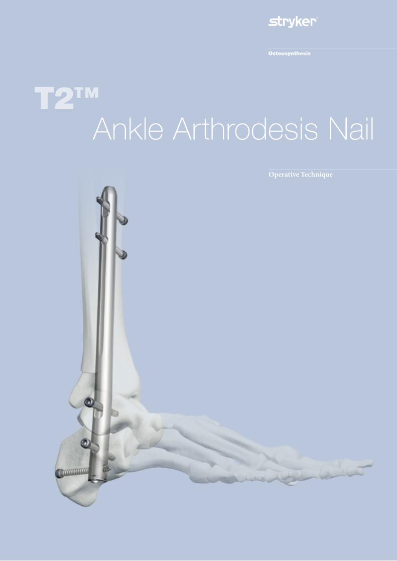
Operative Technique
T2™Ankle Arthrodesis Nail
Ankle Arthrodesis Nailing System
Contributing Surgeons
Joseph D. DiCicco D.O. Chief Orthopedic Trauma Good Samaritan Hospital Chairman, Dept of Orthopaedic SurgeryGrandview Hospital, Dayton, Ohio Clinical Professor Orthopaedic Surgery Ohio University & Wright State University Dayton, Ohio
Thomas Mückley, M.D.Department of Trauma, Hand and Reconstructive SurgeryUniversity Hospital JenaGermany
Anthony T. Sorkin, M.D.Rockford Orthopaedic Associates, LLPClinical Instructor, Department of SurgeryUniversity of Illinois, College of MedicineDirector, Orthopaedic TraumatologyRockford Memorial HospitalRockford, Illinois, USA
This publication sets forth detailed recommended procedures for using Stryker Osteosynthesis devices and instruments.
It offers guidance that you should heed, but, as with any such technical guide, each surgeon must consider the particular needs of each patient and make appropriate adjustments when and as required.
A workshop training is required prior to first surgery.
2

4
4
4
6
7
7
7
8
8
9
11
12
13
14
14
20
23
24
25
26
27
28
27
Contents
1. Introduction
1.1. Implant Features
1.2. Design Rationale
1.3. Instrument Features
2. Indications and Contraindications
3. Pre-operative Planning
4. Locking Options
5. Operative Technique
5.1. Patient Positioning and Joint Surface Preparation
5.2. Incision and Entry Point
5.3. Reaming
5.4. Target Device Assembly
5.5. Nail Insertion
5.6. Guided Locking via Target Device
5.6.1. Apposition/Compression Locking Mode
5.6.2. Static Locking Mode
5.7. Freehand Proximal Locking of Long Nails
5.8. End Cap Insertion
5.9. Nail Removal
6. Case Report
7. References
Ordering Information – Implants
Ordering Information – Instruments
3
1.2. Design Rationale
The T2™ Ankle Arthrodesis Nail offers strong biomechanical* intramedullary stabilization using cannulated implants for the tibiotalocalcaneal fusion.
All implants of the T2™ Ankle Arthrodesis Nailing System are made of Type II anodized titanium alloy (Ti6Al4V) for enhanced biomechanical and biomedical performance*.
Standard 5mm cortical screws simplify the surgical procedure and offer the advantages of both reduced insertion torque and low profile heads*. Fully Threaded Locking Screws are available for standard locking procedures. Partially Threaded Locking Screws (Shaft Screws) are designed for use if apposition/compression is applied.
The proximal locking configuration features a round and an oblong hole to allow for static or dynamic locking.Controlled apposition/compression up to 5mm can be applied at the tibio-talar joint by introducing a Compression Screw from the driving end of the nail against the 5mm Shaft Screw placed in the talus. The Compression Screw is cannulated therefore allowing nail insertion over the guide-wire with the compression screw pre-loaded.
T2™ Ankle Arthrodesis Nails come in 10, 11 and 12mm diameters and 150, 200 and 300mm lengths. The driving end diameter is 12mm for all nails.
The design of the T2™ Ankle Arthrodesis Nail features a 5° lateral (valgus) bend providing an anatomical fit with better purchase through the calacaneal bone.
Proximal locking is performed from medial to lateral in order to:
• Avoid damage of muscular and neuro-vascular stuctures located on the lateral side of the tibia • Avoid interference with the fibula.
The low profile design of T2™ Locking Screws helps reduce prominence under the soft tissue on the medial cortex of the tibia.
Two 5mm Fully Threaded Locking Screws can be placed in the calcaneus: the proximal one in a L/M direction through a threaded locking hole, and the distal one in P/A direction with a 10° angle from postero-medial to antero-lateral (Fig. 1). This design dictates the need for left and right nails.Internal compression techniques are preferred because of higher union rates, shorter fusion times, and fewercomplications (2).
End Caps in different sizes are available to provide the “best fit” for every indication and lock down on the PA calcaneal screw. This feature creates a fixed angle between the nail and LockingScrew.
See the detailed chart on the next page for the design specifications and size offerings of the implants.
The T2™ Nailing System represents the latest and most comprehensive development of the original intramedullary principles presented by Prof. Gerhard Küntscher in 1940. With a new generation of T2™ Nails (e.g T2™ Proximal Humeral Nail, T2™ Supracondylar Nail, T2™ Recon Nail), the indications have extended from shaft fractures to fractures of the metaphyseal regions.
In addition to the T2™ Nailing systems for Femoral, Tibial, and Humeral fractures, Stryker Osteosynthesis has developed the T2™ Knee Arthrodesis Nail and, more recently, the T2™ Ankle Arthrodesis Nail to provide the option for tibiotalocalcaneal fusion with a retrograde intramedullary nail.The main advantages of the technique are limited soft tissue damage in the ankle area, high primary stability allowing early weight bearing, (3) as well as compression of the subtalar and tibiotalar joints (5).
Severe arthrosis and deformity of the ankle and subtalar joints are debilitating problems that can be difficult to treat. The tibiotalocalcaneal fusion with a retrograde intramedullary nail can be considered a salvage procedure for severe arthrosis and deformity of the ankle and subtalar joints (1).Ankle arthrodesis is a challenging procedure due to poor host conditions (e.g. bad skin, deformity, avascular necrosis), inability to get adequate fixation for this slow healing process, and the inability to get adequate compression across the fusion.Like other nails in the T2™ family, the T2™ Ankle Arthrodesis Nail enables the surgeon to create an inherently stable construct by providing internal compression to the fusion mass and distal crosslock holes within the nail to generate an intramedullary fixed-angle device.Performing an ankle arthrodesis can be technically demanding because of the shape and small size of the talus. Therefore, preoperative planning is an absolute necessity to determine placement and number of screws (2).
The T2™ Ankle Arthrodesis Nailing System is based on the established T2™ instrument platform and locking screws. It offers the advantages of a unique locking configuration allowing for tibiotalocalcaneal fixation.
Introduction
1. Introduction 1.1. Implant Features
* Data on file at Stryker:
- Test Report No 130505CG1 Strength calculation (FEA) of 10mm T2 Ankle Arthrodesis Nail
- White Paper: Ti6Al4V with Anodization Type II Biological Behavior and Biomechanical Effects Axel Baumann, Dipl.-Ing. DOT GmbH, Rostock, Germany, Nils Zander, Dipl.-Ing. Stryker Trauma GmbH, Schönkirchen / Kiel, Germany
- Test Report 080103HK1 T2 / S2: Modified screw head design of cross screws Ø4 / 5mm
4
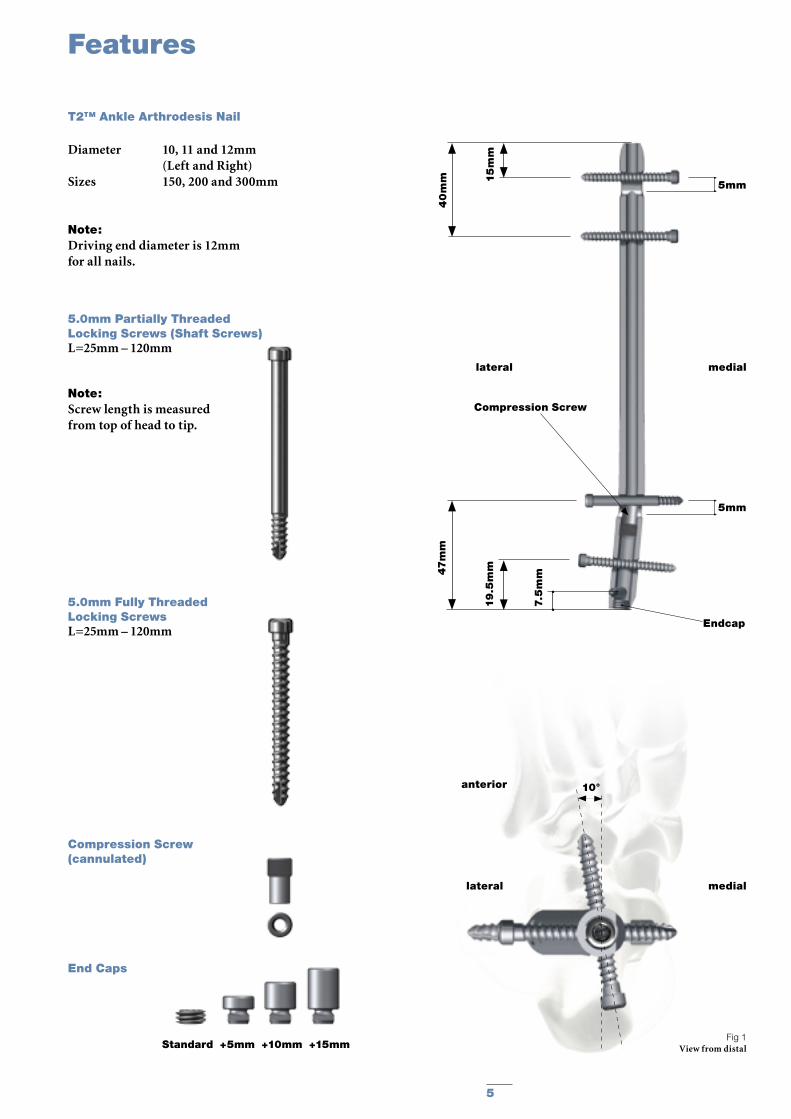
Fig 1View from distal
T2™ Ankle Arthrodesis Nail
5.0mm Partially Threaded Locking Screws (Shaft Screws)L=25mm – 120mm
Note:Screw length is measured from top of head to tip.
5.0mm Fully Threaded Locking ScrewsL=25mm – 120mm
Compression Screw (cannulated)
End Caps
Features
Diameter 10, 11 and 12mm (Left and Right)Sizes 150, 200 and 300mm
Note:Driving end diameter is 12mm for all nails.
5
10°anterior
Standard +5mm +10mm +15mm
lateral medial
Endcap
Compression Screw
lateral medial
5mm
47m
m
19
.5m
m
7.5
mm
5mm
40
mm 1
5m
m
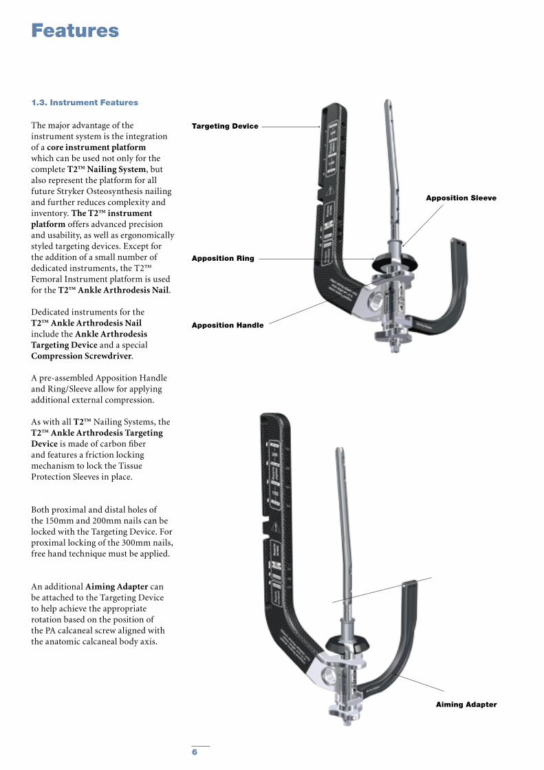
The major advantage of the instrument system is the integration of a core instrument platform which can be used not only for the complete T2™ Nailing System, but also represent the platform for all future Stryker Osteosynthesis nailing and further reduces complexity and inventory. The T2™ instrument platform offers advanced precision and usability, as well as ergonomically styled targeting devices. Except for the addition of a small number of dedicated instruments, the T2™ Femoral Instrument platform is used for the T2™ Ankle Arthrodesis Nail.
Dedicated instruments for the T2™ Ankle Arthrodesis Nail include the Ankle Arthrodesis Targeting Device and a special Compression Screwdriver.
A pre-assembled Apposition Handle and Ring/Sleeve allow for applying additional external compression.
As with all T2™ Nailing Systems, the T2™ Ankle Arthrodesis Targeting Device is made of carbon fiber and features a friction locking mechanism to lock the Tissue Protection Sleeves in place.
Both proximal and distal holes of the 150mm and 200mm nails can be locked with the Targeting Device. For proximal locking of the 300mm nails, free hand technique must be applied.
An additional Aiming Adapter can be attached to the Targeting Device to help achieve the appropriate rotation based on the position of the PA calcaneal screw aligned with the anatomic calcaneal body axis.
Features
1.3. Instrument Features
Aiming Adapter
6
Apposition Handle
Apposition Ring
Apposition Sleeve
Targeting Device
Indications
2. Indications and Contraindications
The T2™ Ankle Arthrodesis Nail may be used for:
• Posttraumatic and primary Arthrosis
• Neuromuscular deformity • Revision of Failed Ankle
Arthrodesis • Failed Total Ankle Replacement• Avascular Necrosis of the
Talus (requiring tibiocalcaneal arthrodesis)
• Neuroarthropathy (Charcot)• Rheumatoid Arthritis with
severe deformity• Osteoarthritis• Pseudarthrosis
The T2™ Ankle Arthrodesis Nail should NOT be used if following conditions are present:
• Tibial malalignment of > 10˚ in any plane
• Severe vascular deficiency• Osteomyelitis or soft tissue
infection
Note:Please see package insert for warnings, precautions, adverse effects and other essential product information.
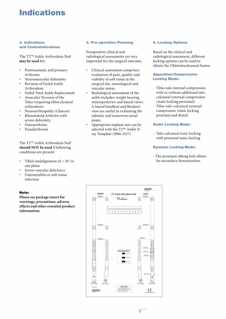
3. Pre-operative Planning
Preoperative clinical and radiological assessments are very important for the surgical outcome.
• Clinical assessment comprises: evaluation of pain, quality and viability of soft tissue at the surgical site, neurological and vascular status.
• Radiological assessment of the ankle includes: weight bearing anteroposterior and lateral views. A lateral hindfoot and Broden’s view are useful in evaluating the subtalar and transverse tarsal joints.
• Appropriate implant size can be selected with the T2™ Ankle X-ray Template (1806-3217).
4. Locking Options
Based on the clinical and radiological assessment, different locking options can be used to obtain the Tibiotalocalcaneal fusion:
Apposition/Compression Locking Mode:
- Tibio-talo internal compression with or without additional talo-calcaneal external compression (static locking proximal)
- Tibio-talo-calcaneal external compression (static locking proximal and distal)
Static Locking Mode:
- Talo-calcaneal static locking with proximal static locking
Dynamic Locking Mode:
- The proximal oblong hole allows for secondary dynamization
Manufacturer:
Stryker Trauma GmbHProf.-Küntscher Strasse 1-5D - 24232 SchönkirchenGermany
Cat.Nr.:1806-3217/Rev.00
Osteosynthesis
Please Note:
All dimensions resulting from theuse of this template has to beverified intraoperatively, to ensureproper implant selection.
T2 Ankle Arthrodesis Nail
Scale: 1,10 : 110 % Magnification
0 10 20 30 40 50 60 70 80 90 100 110 120
L
Nail diameters
Ø10mm
Ø12mm
Ø11mm
Ø12mm
Ø11mm
Ø10mm
LEFT
A-P view M-L view
Ø12mm
RIGHT
M-L view A-P view
300mm 300mm
200mm 200mm
150mm150mm
7
Apposition Sleeve
Operative Technique
5.1 Patient Positioning and Joint surface preparation
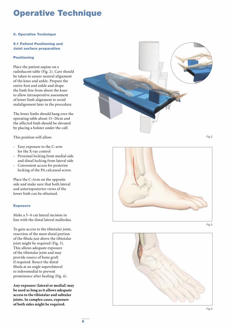
Positioning
Place the patient supine on a radiolucent table (Fig. 2). Care should be taken to assure neutral alignment of the knee and ankle. Prepare the entire foot and ankle and drape the limb free from above the knee to allow intraoperative assessment of lower limb alignment to avoid malalignment later in the procedure.
The lower limbs should hang over the operating table about 15−20cm and the affected limb should be elevated by placing a bolster under the calf.
This position will allow:
- Easy exposure to the C-arm for the X-ray control
- Proximal locking from medial side and distal locking from lateral side
- Convenient access for posterior locking of the PA calcaneal screw.
Place the C-Arm on the opposite side and make sure that both lateral and anterioposterior views of the lower limb can be obtained.
Exposure
Make a 5−6 cm lateral incision in line with the distal lateral malleolus.
To gain access to the tibiotalar joint, resection of the most distal portion of the fibula just above the tibiotalar joint might be required (Fig. 3).This allows adequate exposure of the tibiotalar joint and may provide source of bone graft if required. Resect the distal fibula at an angle superolateral to inferomedial to prevent prominence after healing (Fig. 4).
Any exposure (lateral or medial) may be used as long as it allows adequate access to the tibiotalar and subtalar joints. In complex cases, exposure of both sides might be required.
5. Operative Technique
8
Fig 3
Fig 2
Fig 4
Joint Preparation
Correction of any deformity should be addressed at this time. Generally, the contours of the tibiotalar and subtalar joints are maintained with denuding of any articular cartilage.
Sometimes a “flat on flat” surface can be used depending on surgeon preference. Tibiotalar joint preparation may be aided by a laminar spreader or distraction of some kind. Care should be taken to avoid excessive bony resection which may later result in limb shortening or loss of talar fixation.
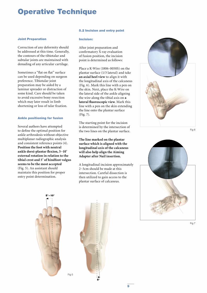
Ankle positioning for fusion
Several authors have attempted to define the optimal position for ankle arthrodesis without objective multiplanar radiographic analysis and consistent reference points (4).Position the foot with neutral ankle dorsi-plantar flexion, 5−10˚ external rotation in relation to the tibial crest and 5˚ of hindfoot valgus seems to be the most accepted (Fig. 5). An assistant should maintain this position for proper entry point determination.
5.2 Incision and entry point
Incision:
After joint preparation and confirmatory X-ray evaluation of fusion position, the incision point is determined as follows:
Place a K-Wire (1806-0050S) on the plantar surface (1/3 lateral) and take an axial heel view to align it with the longitudinal axis of the calcaneus (Fig. 6). Mark this line with a pen on the skin. Next, place the K-Wire on the lateral side of the ankle aligning the wire along the tibial axis on a lateral fluoroscopic view. Mark this line with a pen on the skin extending the line onto the plantar surface (Fig. 7).
The starting point for the incision is determined by the intersection of the two lines on the plantar surface.
The line marked on the plantar surface which is aligned with the longitudinal axis of the calcaneus will also help align the Aiming Adapter after Nail insertion.
A longitudinal incision approximately 2−3cm should be made at this intersection. Careful dissection is then utilized to gain access to the plantar surface of calcaneus.
5°–10°
5°
Operative Technique
9
Fig 5
Fig 6
Fig 7
Operative Technique
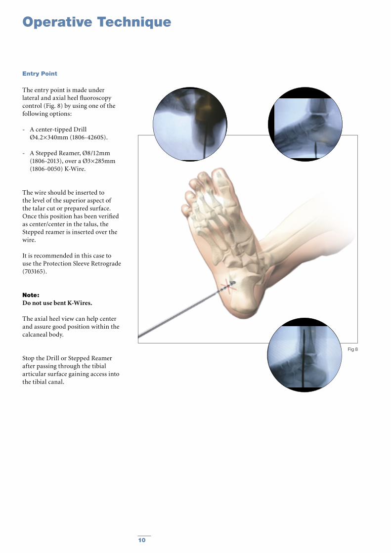
The entry point is made under lateral and axial heel fluoroscopy control (Fig. 8) by using one of the following options:
- A center-tipped Drill Ø4.2×340mm (1806-4260S).
- A Stepped Reamer, Ø8/12mm (1806-2013), over a Ø3×285mm (1806-0050) K-Wire.
The wire should be inserted to the level of the superior aspect of the talar cut or prepared surface. Once this position has been verified as center/center in the talus, the Stepped reamer is inserted over the wire.
It is recommended in this case to use the Protection Sleeve Retrograde (703165).
Note:Do not use bent K-Wires.
The axial heel view can help center and assure good position within the calcaneal body.
Stop the Drill or Stepped Reamer after passing through the tibial articular surface gaining access into the tibial canal.
Entry Point
10
Fig 8
Operative Technique
5.3 Reaming
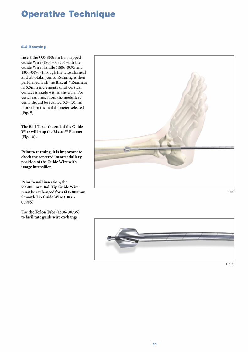
Insert the Ø3×800mm Ball Tipped Guide Wire (1806-0080S) with the Guide Wire Handle (1806-0095 and 1806-0096) through the talocalcaneal and tibiotalar joints. Reaming is then performed with the Bixcut™ Reamers in 0.5mm increments until cortical contact is made within the tibia. For easier nail insertion, the medullary canal should be reamed 0.5−1.0mm more than the nail diameter selected (Fig. 9).
The Ball Tip at the end of the Guide Wire will stop the Bixcut™ Reamer (Fig. 10).
Prior to reaming, it is important to check the centered intramedullary position of the Guide Wire with image intensifier.
Prior to nail insertion, theØ3×800mm Ball Tip Guide Wiremust be exchanged for a Ø3×800mm Smooth Tip Guide Wire (1806-0090S).
Use the Teflon Tube (1806-0073S)to facilitate guide wire exchange.
11
Fig 9
Fig 10
Operative Technique
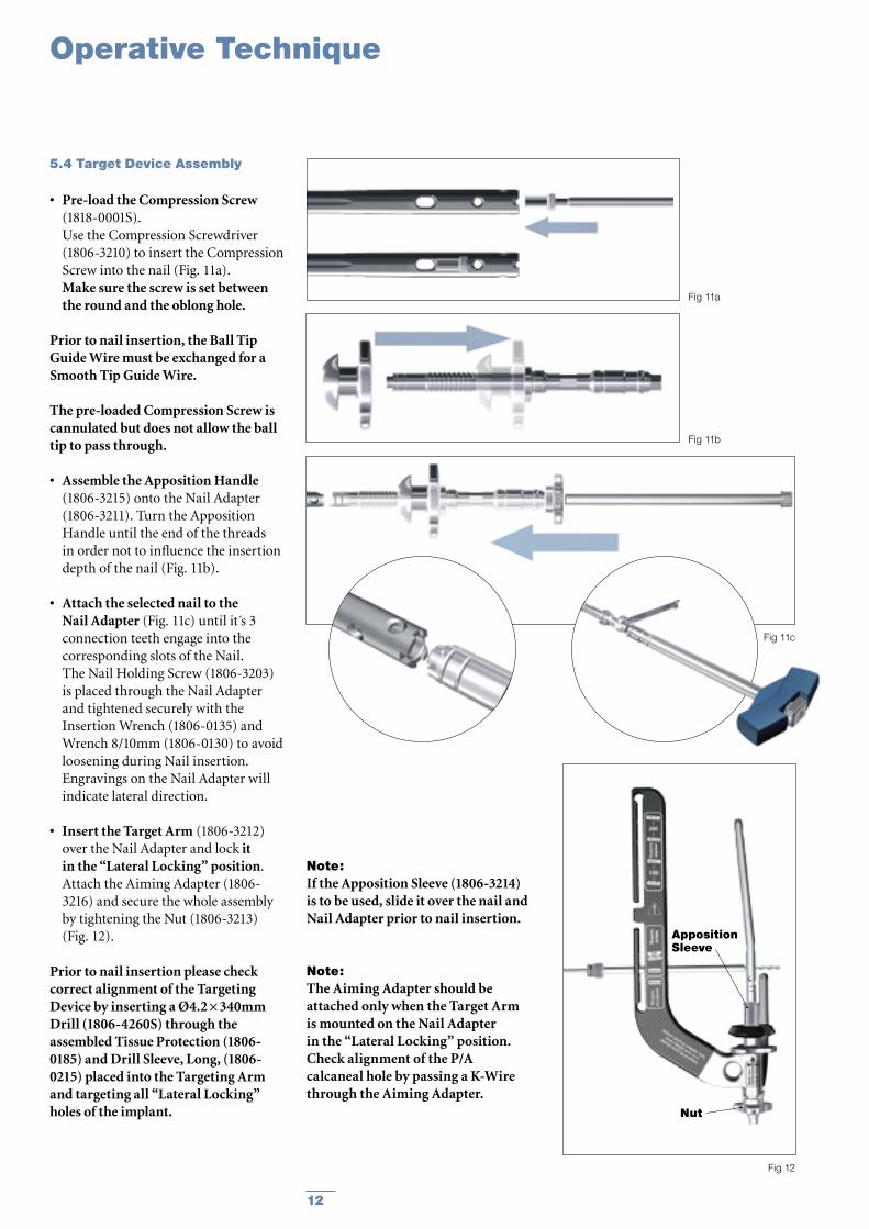
• Pre-load the Compression Screw (1818-0001S).
Use the Compression Screwdriver (1806-3210) to insert the Compression Screw into the nail (Fig. 11a). Make sure the screw is set between the round and the oblong hole.
Prior to nail insertion, the Ball Tip Guide Wire must be exchanged for a Smooth Tip Guide Wire.
The pre-loaded Compression Screw is cannulated but does not allow the ball tip to pass through.
• Assemble the Apposition Handle (1806-3215) onto the Nail Adapter (1806-3211). Turn the Apposition Handle until the end of the threads in order not to influence the insertion depth of the nail (Fig. 11b).
• Attach the selected nail to the Nail Adapter (Fig. 11c) until it s 3
connection teeth engage into the corresponding slots of the Nail.
The Nail Holding Screw (1806-3203) is placed through the Nail Adapter and tightened securely with the Insertion Wrench (1806-0135) and Wrench 8/10mm (1806-0130) to avoid loosening during Nail insertion. Engravings on the Nail Adapter will indicate lateral direction.
• Insert the Target Arm (1806-3212) over the Nail Adapter and lock it in the “Lateral Locking” position. Attach the Aiming Adapter (1806-3216) and secure the whole assembly by tightening the Nut (1806-3213) (Fig. 12).
5.4 Target Device Assembly
Prior to nail insertion please check correct alignment of the Targeting Device by inserting a Ø4.2 × 340mm Drill (1806-4260S) through the assembled Tissue Protection (1806-0185) and Drill Sleeve, Long, (1806-0215) placed into the Targeting Arm and targeting all “Lateral Locking” holes of the implant.
12
Note:If the Apposition Sleeve (1806-3214) is to be used, slide it over the nail and Nail Adapter prior to nail insertion.
Note:The Aiming Adapter should be attached only when the Target Arm is mounted on the Nail Adapter in the “Lateral Locking” position. Check alignment of the P/A calcaneal hole by passing a K-Wire through the Aiming Adapter.
Fig 11a
Fig 12
Fig 11c
Fig 11b
Apposition Sleeve
Nut
Operative Technique
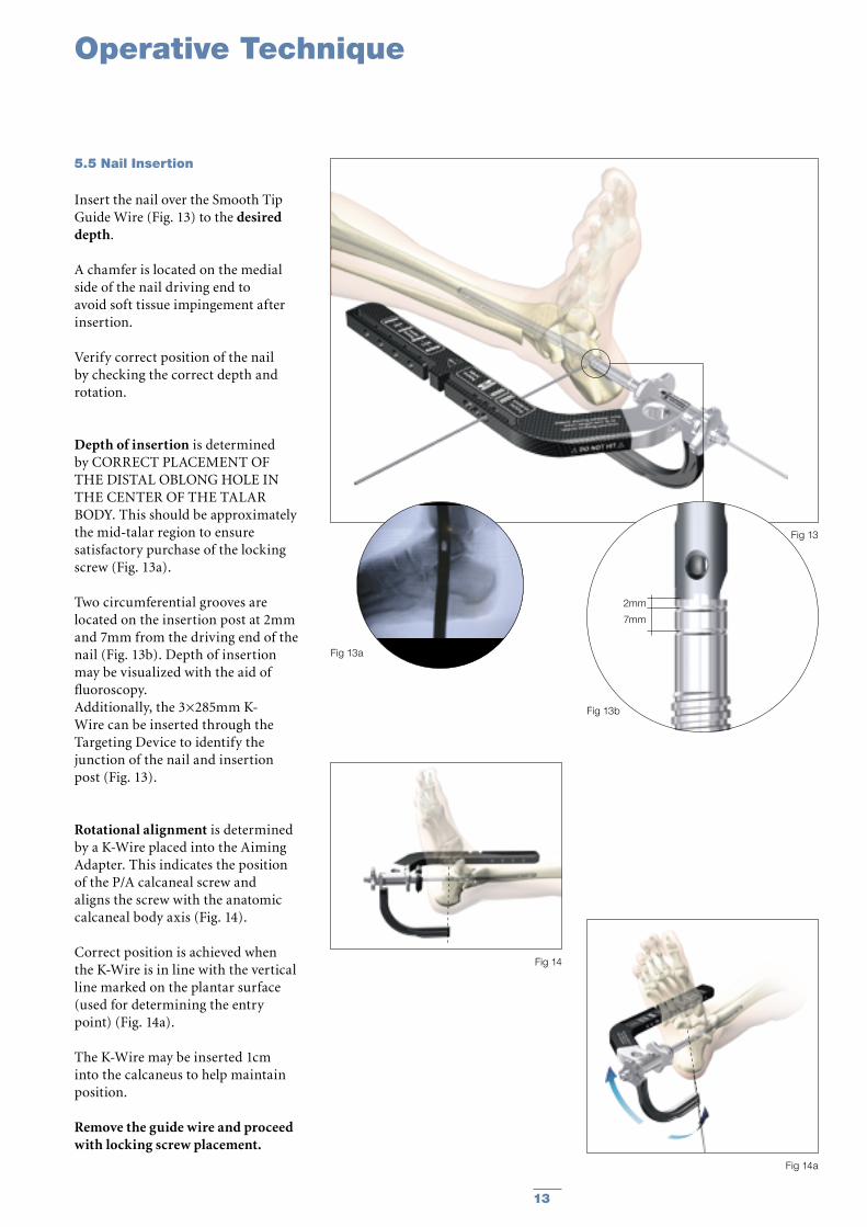
Insert the nail over the Smooth Tip Guide Wire (Fig. 13) to the desired depth.
A chamfer is located on the medial side of the nail driving end to avoid soft tissue impingement after insertion.
Verify correct position of the nail by checking the correct depth and rotation.
Depth of insertion is determined by CORRECT PLACEMENT OF THE DISTAL OBLONG HOLE IN THE CENTER OF THE TALAR BODY. This should be approximately the mid-talar region to ensure satisfactory purchase of the locking screw (Fig. 13a).
Two circumferential grooves are located on the insertion post at 2mm and 7mm from the driving end of the nail (Fig. 13b). Depth of insertion may be visualized with the aid of fluoroscopy.Additionally, the 3×285mm K-Wire can be inserted through the Targeting Device to identify the junction of the nail and insertion post (Fig. 13).
Rotational alignment is determined by a K-Wire placed into the Aiming Adapter. This indicates the position of the P/A calcaneal screw and aligns the screw with the anatomic calcaneal body axis (Fig. 14).
Correct position is achieved when the K-Wire is in line with the vertical line marked on the plantar surface (used for determining the entry point) (Fig. 14a).
The K-Wire may be inserted 1cm into the calcaneus to help maintain position.
Remove the guide wire and proceed with locking screw placement.
5.5 Nail Insertion
13
Fig 13a
Fig 13b
Fig 13
Fig 14
Fig 14a
7mm
2mm
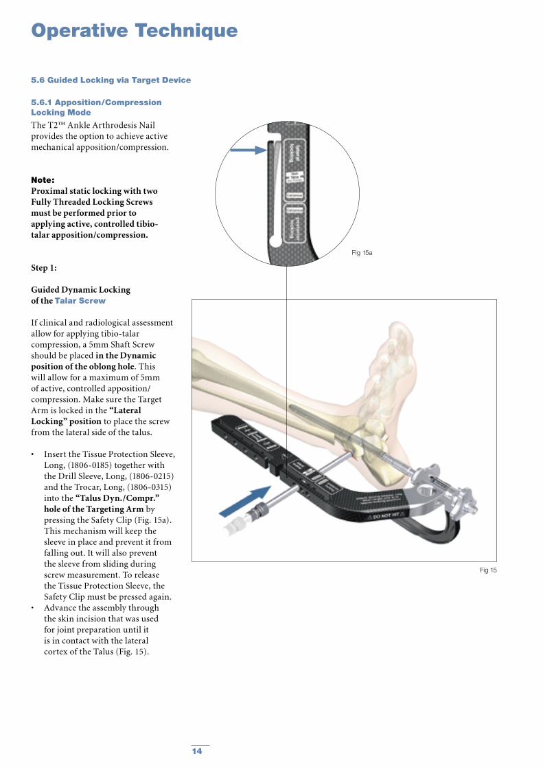
The T2™ Ankle Arthrodesis Nail provides the option to achieve active mechanical apposition/compression.
Note: Proximal static locking with two Fully Threaded Locking Screws must be performed prior to applying active, controlled tibio-talar apposition/compression.
Step 1:
Guided Dynamic Locking of the Talar Screw
If clinical and radiological assessment allow for applying tibio-talar compression, a 5mm Shaft Screw should be placed in the Dynamic position of the oblong hole. This will allow for a maximum of 5mm of active, controlled apposition/compression. Make sure the Target Arm is locked in the “Lateral Locking” position to place the screw from the lateral side of the talus.
• Insert the Tissue Protection Sleeve, Long, (1806-0185) together with the Drill Sleeve, Long, (1806-0215) and the Trocar, Long, (1806-0315) into the “Talus Dyn./Compr.” hole of the Targeting Arm by pressing the Safety Clip (Fig. 15a). This mechanism will keep the sleeve in place and prevent it from falling out. It will also prevent the sleeve from sliding during screw measurement. To release the Tissue Protection Sleeve, the Safety Clip must be pressed again.
• Advance the assembly through the skin incision that was used for joint preparation until it is in contact with the lateral cortex of the Talus (Fig. 15).
Operative Technique
5.6 Guided Locking via Target Device
5.6.1 Apposition/Compression Locking Mode
14
Fig 15a
Fig 15
Operative Technique
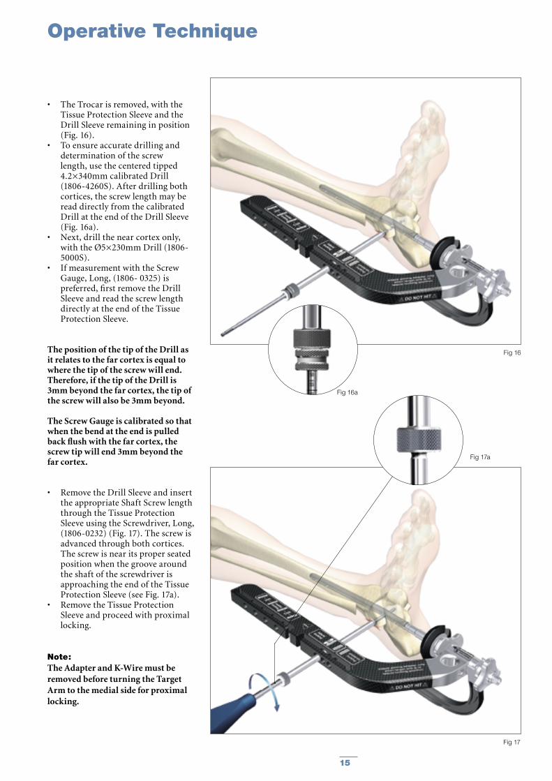
• The Trocar is removed, with the Tissue Protection Sleeve and the Drill Sleeve remaining in position (Fig. 16).
• To ensure accurate drilling and determination of the screw length, use the centered tipped 4.2×340mm calibrated Drill (1806-4260S). After drilling both cortices, the screw length may be read directly from the calibrated Drill at the end of the Drill Sleeve (Fig. 16a).
• Next, drill the near cortex only, with the Ø5×230mm Drill (1806-5000S).
• If measurement with the Screw Gauge, Long, (1806- 0325) is preferred, first remove the Drill Sleeve and read the screw length directly at the end of the Tissue Protection Sleeve.
The position of the tip of the Drill as it relates to the far cortex is equal to where the tip of the screw will end.Therefore, if the tip of the Drill is 3mm beyond the far cortex, the tip of the screw will also be 3mm beyond.
The Screw Gauge is calibrated so that when the bend at the end is pulled back flush with the far cortex, the screw tip will end 3mm beyond the far cortex.
• Remove the Drill Sleeve and insert the appropriate Shaft Screw length through the Tissue Protection Sleeve using the Screwdriver, Long, (1806-0232) (Fig. 17). The screw is advanced through both cortices. The screw is near its proper seated position when the groove around the shaft of the screwdriver is approaching the end of the Tissue Protection Sleeve (see Fig. 17a).
• Remove the Tissue Protection Sleeve and proceed with proximal locking.
Note:The Adapter and K-Wire must be removed before turning the Target Arm to the medial side for proximal locking.
15
Fig 16
Fig 16a
Fig 17a
Fig 17
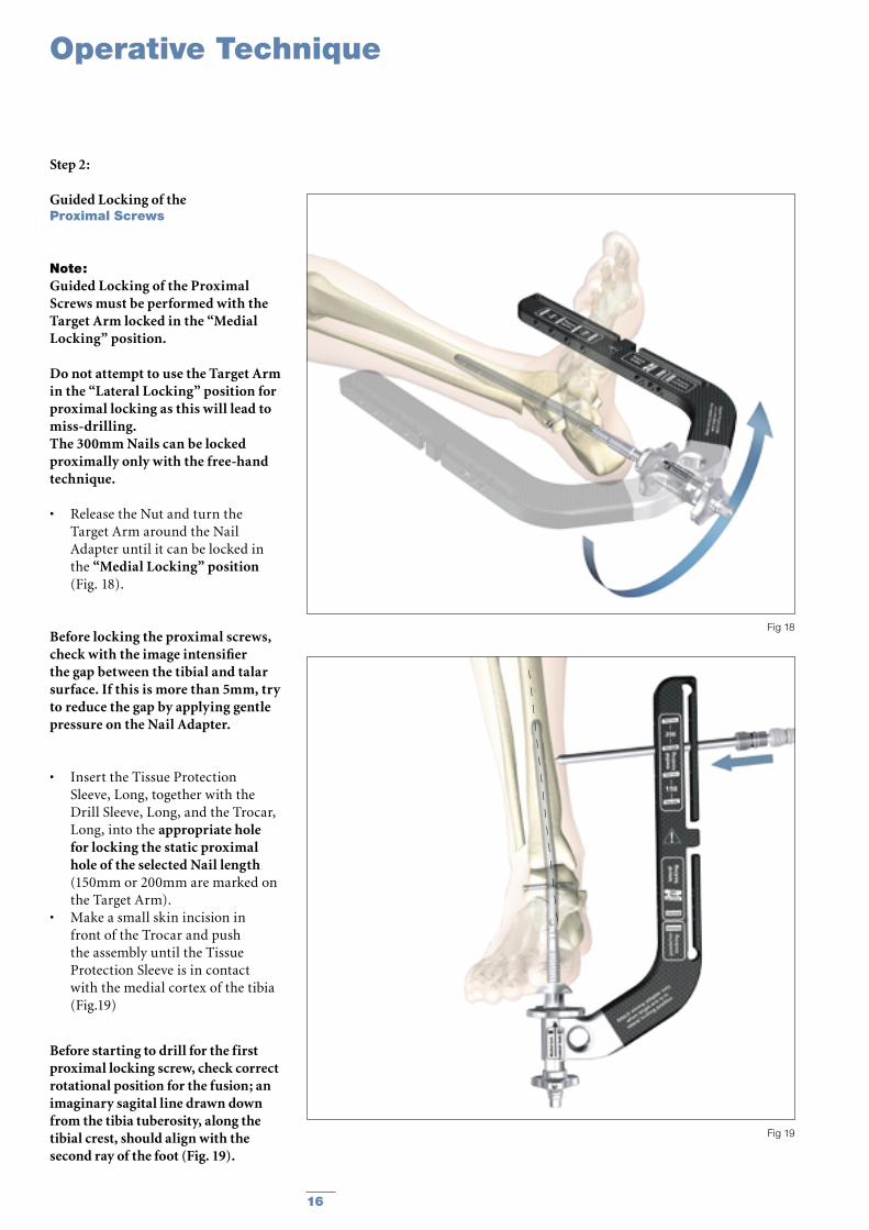
Step 2:
Guided Locking of the Proximal Screws
Note:Guided Locking of the Proximal Screws must be performed with the Target Arm locked in the “Medial Locking” position.
Do not attempt to use the Target Arm in the “Lateral Locking” position for proximal locking as this will lead to miss-drilling.The 300mm Nails can be locked proximally only with the free-hand technique.
• Release the Nut and turn the Target Arm around the Nail Adapter until it can be locked in the “Medial Locking” position (Fig. 18).
Before locking the proximal screws, check with the image intensifier the gap between the tibial and talar surface. If this is more than 5mm, try to reduce the gap by applying gentle pressure on the Nail Adapter.
• Insert the Tissue Protection Sleeve, Long, together with the Drill Sleeve, Long, and the Trocar, Long, into the appropriate hole for locking the static proximal hole of the selected Nail length (150mm or 200mm are marked on the Target Arm).
• Make a small skin incision in front of the Trocar and push the assembly until the Tissue Protection Sleeve is in contact with the medial cortex of the tibia (Fig.19)
Operative Technique
Before starting to drill for the first proximal locking screw, check correct rotational position for the fusion; an imaginary sagital line drawn down from the tibia tuberosity, along the tibial crest, should align with the second ray of the foot (Fig. 19).
16
Fig 18
Fig 19
Operative Technique
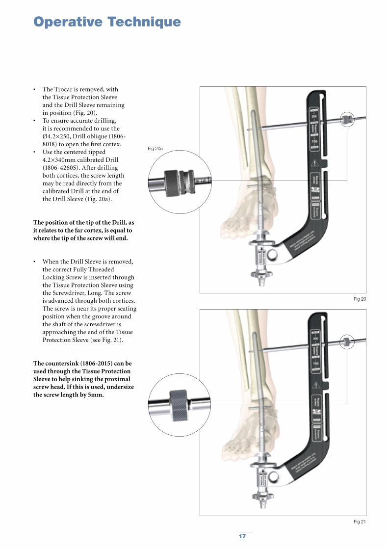
• The Trocar is removed, with the Tissue Protection Sleeve and the Drill Sleeve remaining in position (Fig. 20).
• To ensure accurate drilling, it is recommended to use the Ø4.2×250, Drill oblique (1806-8018) to open the first cortex.
• Use the centered tipped 4.2×340mm calibrated Drill (1806-4260S). After drilling both cortices, the screw length may be read directly from the calibrated Drill at the end of the Drill Sleeve (Fig. 20a).
The position of the tip of the Drill, as it relates to the far cortex, is equal to where the tip of the screw will end.
• When the Drill Sleeve is removed, the correct Fully Threaded Locking Screw is inserted through the Tissue Protection Sleeve using the Screwdriver, Long. The screw is advanced through both cortices. The screw is near its proper seating position when the groove around the shaft of the screwdriver is approaching the end of the Tissue Protection Sleeve (see Fig. 21).
The countersink (1806-2015) can beused through the Tissue Protection Sleeve to help sinking the proximal screw head. If this is used, undersize the screw length by 5mm.
17
Fig 20
Fig 21
Fig 20a
Operative Technique
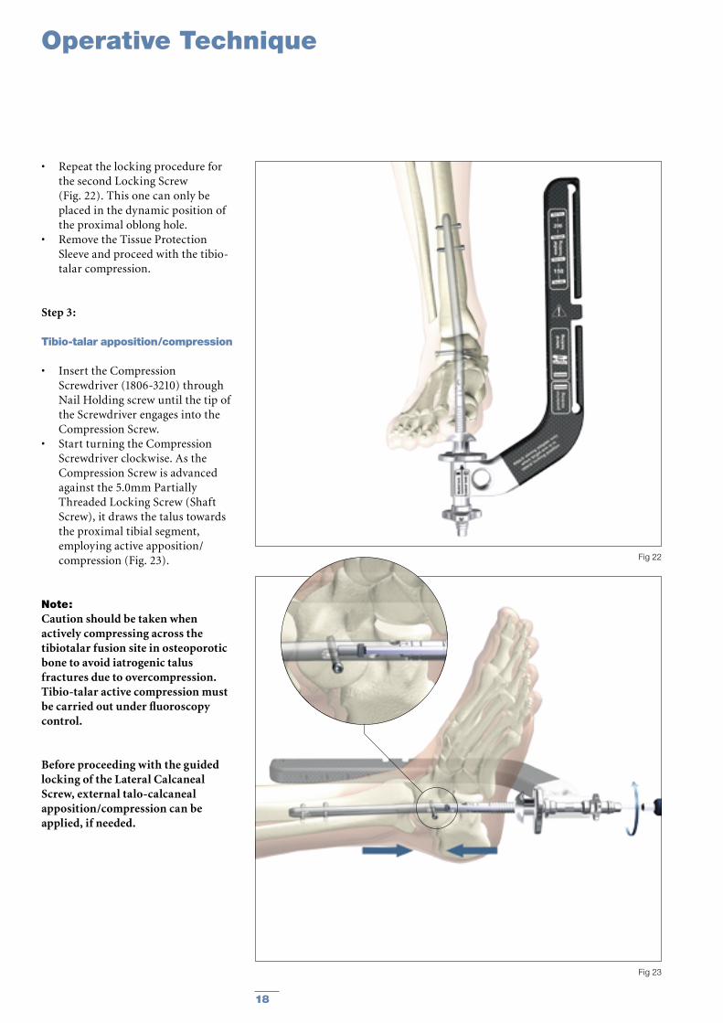
• Repeat the locking procedure for the second Locking Screw (Fig. 22). This one can only be placed in the dynamic position of the proximal oblong hole.
• Remove the Tissue Protection Sleeve and proceed with the tibio-talar compression.
Step 3:
Tibio-talar apposition/compression
• Insert the Compression Screwdriver (1806-3210) through Nail Holding screw until the tip of the Screwdriver engages into the Compression Screw.
• Start turning the Compression Screwdriver clockwise. As the Compression Screw is advanced against the 5.0mm Partially Threaded Locking Screw (Shaft Screw), it draws the talus towards the proximal tibial segment, employing active apposition/compression (Fig. 23).
Note:Caution should be taken when actively compressing across the tibiotalar fusion site in osteoporotic bone to avoid iatrogenic talus fractures due to overcompression. Tibio-talar active compression must be carried out under fluoroscopy control.
Before proceeding with the guided locking of the Lateral Calcaneal Screw, external talo-calcaneal apposition/compression can be applied, if needed.
18
Fig 22
Fig 23
Operative Technique
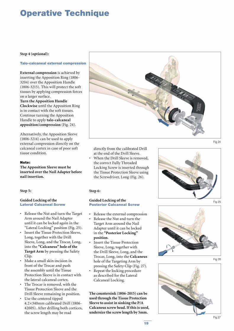
Step 4 (optional):
External compression is achieved by inserting the Apposition Ring (1806-3204) over the Apposition Handle (1806-3215). This will protect the soft tissues by applying compression forces on a larger surface. Turn the Apposition Handle Clockwise until the Apposition Ring is in contact with the soft tissues. Continue turning the Apposition Handle to apply talo-calcaneal apposition/compression (Fig. 24).
Alternatively, the Apposition Sleeve (1806-3214) can be used to apply external compression directly on the calcaneal cortex in case of poor soft tissue condition.
Note:The Apposition Sleeve must be inserted over the Nail Adapter before nail insertion.
Step 5:
Guided Locking of the Lateral Calcaneal Screw
• Release the Nut and turn the Target Arm around the Nail Adapter until it can be locked again in the “Lateral Locking” position (Fig. 25).
• Insert the Tissue Protection Sleeve, Long, together with the Drill Sleeve, Long, and the Trocar, Long, into the “Calcaneus” hole of the Target Arm by pressing the Safety Clip.
• Make a small skin incision in front of the Trocar and push the assembly until the Tissue Protection Sleeve is in contact with the lateral calcaneal cortex.
• The Trocar is removed, with the Tissue Protection Sleeve and the Drill Sleeve remaining in position.
• Use the centered tipped 4.2×340mm calibrated Drill (1806-4260S). After drilling both cortices, the screw length may be read
Talo-calcaneal external compression
Step 6:
Guided Locking of the Posterior Calcaneal Screw
• Release the external compression• Release the Nut and turn the
Target Arm around the Nail Adapter until it can be locked in the “Posterior Locking” position.
• Insert the Tissue Protection Sleeve, Long, together with the Drill Sleeve, Long, and the Trocar, Long, into the Calcaneus hole of the Targeting Arm by pressing the Safety Clip (Fig. 27).
• Repeat the locking procedure as described for the Lateral Calcaneal Locking.
The countersink (1806-2015) can be used through the Tissue Protection Sleeve to assist in sinking the P/A Calcaneus screw head. If this is used, undersize the screw length by 5mm.
directly from the calibrated Drill at the end of the Drill Sleeve.
• When the Drill Sleeve is removed, the correct Fully Threaded Locking Screw is inserted through the Tissue Protection Sleeve using the Screwdriver, Long (Fig. 26).
19
Fig 24
Fig 25
Fig 27
Fig 26
Operative Technique
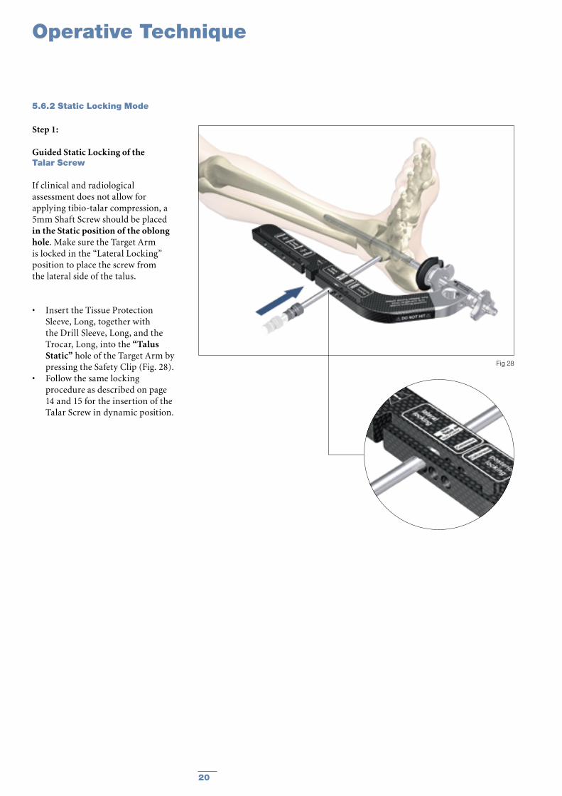
Step 1:
Guided Static Locking of the Talar Screw
If clinical and radiological assessment does not allow for applying tibio-talar compression, a 5mm Shaft Screw should be placed in the Static position of the oblong hole. Make sure the Target Arm is locked in the “Lateral Locking” position to place the screw from the lateral side of the talus.
• Insert the Tissue Protection Sleeve, Long, together with the Drill Sleeve, Long, and the Trocar, Long, into the “Talus Static” hole of the Target Arm by pressing the Safety Clip (Fig. 28).
• Follow the same locking procedure as described on page 14 and 15 for the insertion of the Talar Screw in dynamic position.
5.6.2 Static Locking Mode
20
Fig 28
Operative Technique
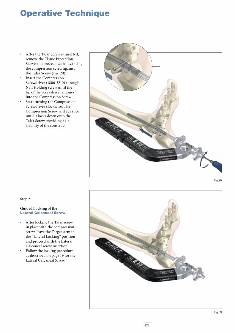
• After the Talar Screw is inserted, remove the Tissue Protection Sleeve and proceed with advancing the compression screw against the Talar Screw (Fig. 29).
• Insert the Compression Screwdriver (1806-3210) through Nail Holding screw until the tip of the Screwdriver engages into the Compression Screw.
• Start turning the Compression Screwdriver clockwise. The Compression Screw will advance until it locks down onto the Talar Screw providing axial stability of the construct.
Step 2:
Guided Locking of the Lateral Calcaneal Screw
• After locking the Talar screw in place with the compression screw, leave the Target Arm in the “Lateral Locking” position and proceed with the Lateral Calcaneal screw insertion.
• Follow the locking procedure as described on page 19 for the Lateral Calcaneal Screw.
21
Fig 29
Fig 30
Operative Technique
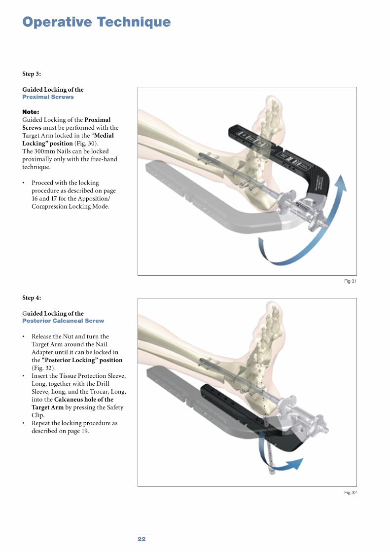
Step 4:
Guided Locking of the Posterior Calcaneal Screw
• Release the Nut and turn the Target Arm around the Nail Adapter until it can be locked in the “Posterior Locking” position (Fig. 32).
• Insert the Tissue Protection Sleeve, Long, together with the Drill Sleeve, Long, and the Trocar, Long, into the Calcaneus hole of the Target Arm by pressing the Safety Clip.
• Repeat the locking procedure as described on page 19.
Step 3:
Guided Locking of the Proximal Screws
Note:Guided Locking of the Proximal Screws must be performed with the Target Arm locked in the “Medial Locking” position (Fig. 30). The 300mm Nails can be locked proximally only with the free-hand technique.
• Proceed with the locking procedure as described on page 16 and 17 for the Apposition/Compression Locking Mode.
22
Fig 31
Fig 32
Operative Technique
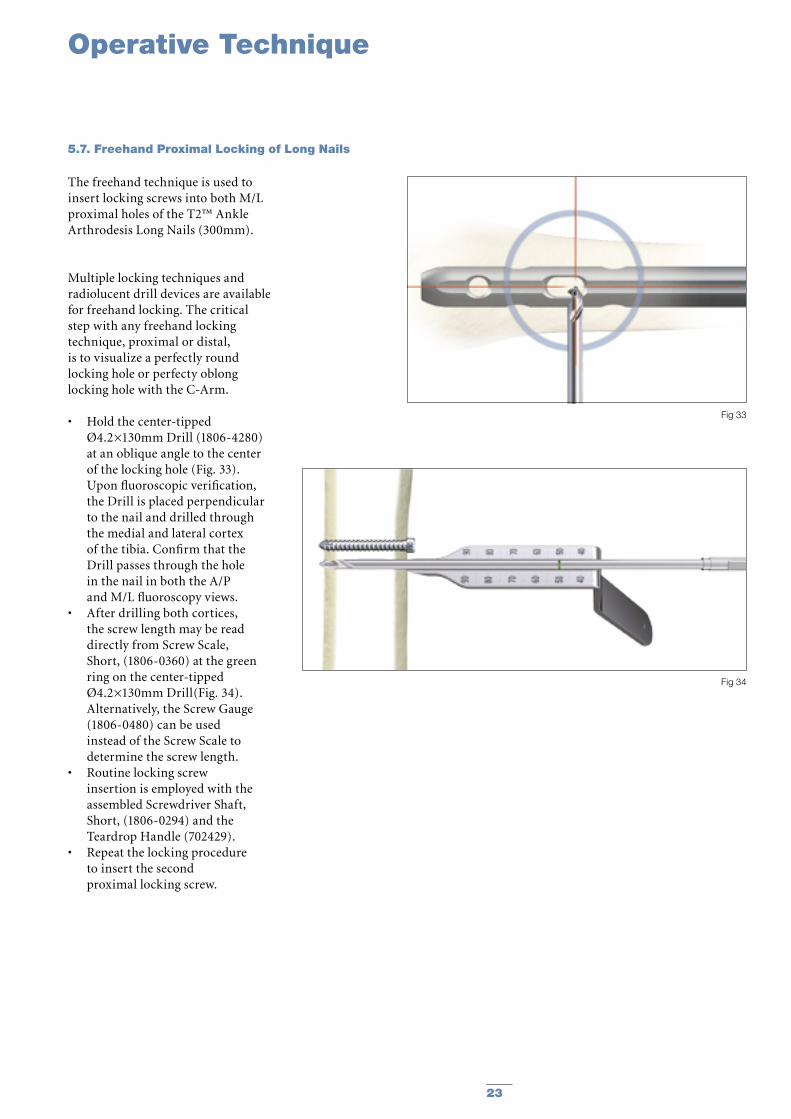
5.7. Freehand Proximal Locking of Long Nails
The freehand technique is used to insert locking screws into both M/L proximal holes of the T2™ Ankle Arthrodesis Long Nails (300mm).
Multiple locking techniques and radiolucent drill devices are available for freehand locking. The critical step with any freehand locking technique, proximal or distal, is to visualize a perfectly round locking hole or perfecty oblong locking hole with the C-Arm.
• Hold the center-tipped Ø4.2×130mm Drill (1806-4280) at an oblique angle to the center of the locking hole (Fig. 33). Upon fluoroscopic verification, the Drill is placed perpendicular to the nail and drilled through the medial and lateral cortex of the tibia. Confirm that the Drill passes through the hole in the nail in both the A/P and M/L fluoroscopy views.
• After drilling both cortices, the screw length may be read directly from Screw Scale, Short, (1806-0360) at the green ring on the center-tipped Ø4.2×130mm Drill(Fig. 34).
Alternatively, the Screw Gauge (1806-0480) can be used instead of the Screw Scale to determine the screw length.
• Routine locking screw insertion is employed with the assembled Screwdriver Shaft, Short, (1806-0294) and the Teardrop Handle (702429).
• Repeat the locking procedure to insert the second proximal locking screw.
23
Fig 33
Fig 34
Operative Technique
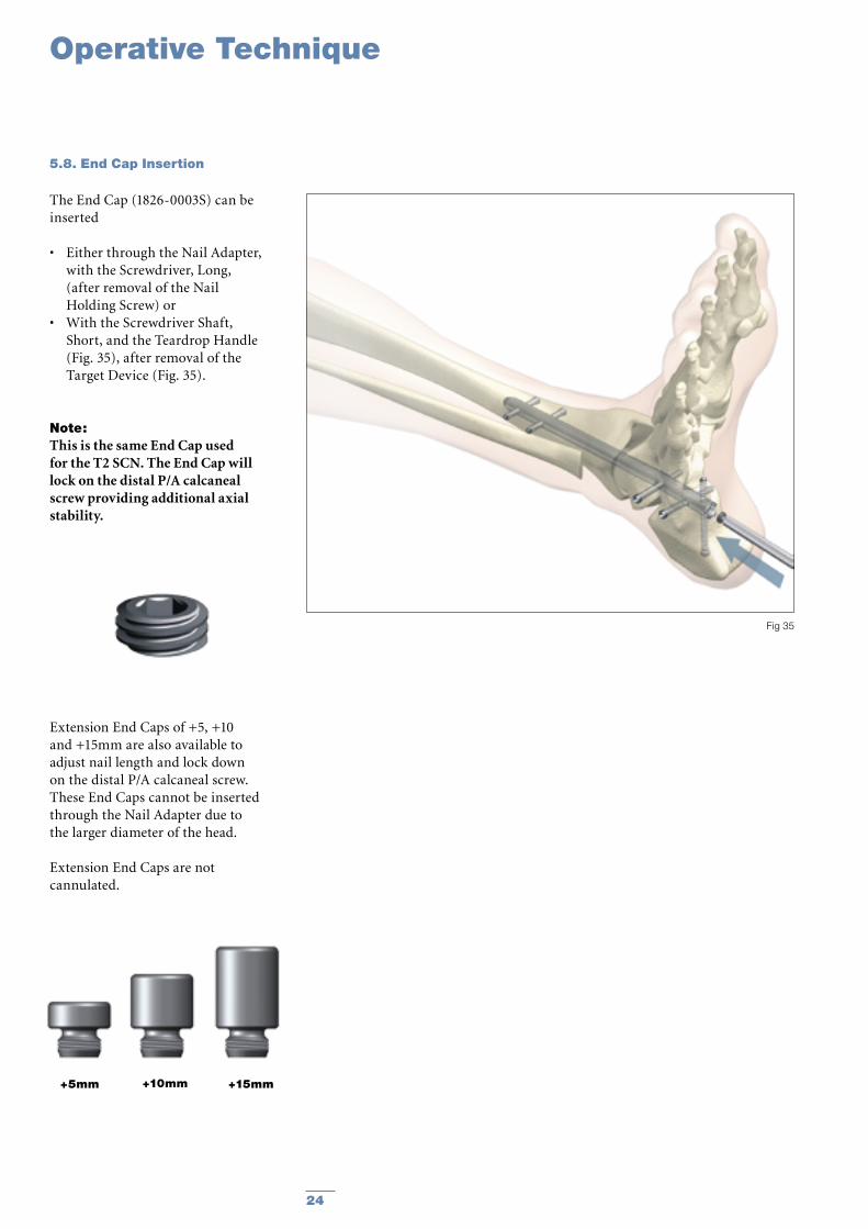
5.8. End Cap Insertion
The End Cap (1826-0003S) can be inserted
• Either through the Nail Adapter, with the Screwdriver, Long, (after removal of the Nail Holding Screw) or
• With the Screwdriver Shaft, Short, and the Teardrop Handle (Fig. 35), after removal of the Target Device (Fig. 35).
Note: This is the same End Cap used for the T2 SCN. The End Cap will lock on the distal P/A calcaneal screw providing additional axial stability.
Extension End Caps of +5, +10 and +15mm are also available to adjust nail length and lock down on the distal P/A calcaneal screw. These End Caps cannot be inserted through the Nail Adapter due to the larger diameter of the head.
Extension End Caps are not cannulated.
+5mm +10mm +15mm
24
Fig 35
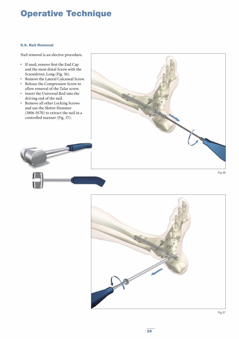
5.9. Nail Removal
Nail removal is an elective procedure.
• If used, remove first the End Cap and the most distal Screw with the Screwdriver, Long (Fig. 36).
• Remove the Lateral Calcaneal Screw. • Release the Compression Screw to
allow removal of the Talar screw.• Insert the Universal Rod into the
driving end of the nail. • Remove all other Locking Screws
and use the Slottet Hammer (1806-0170) to extract the nail in a controlled manner (Fig. 37).
Operative Technique
25
Fig 36
Fig 37
Operative Technique
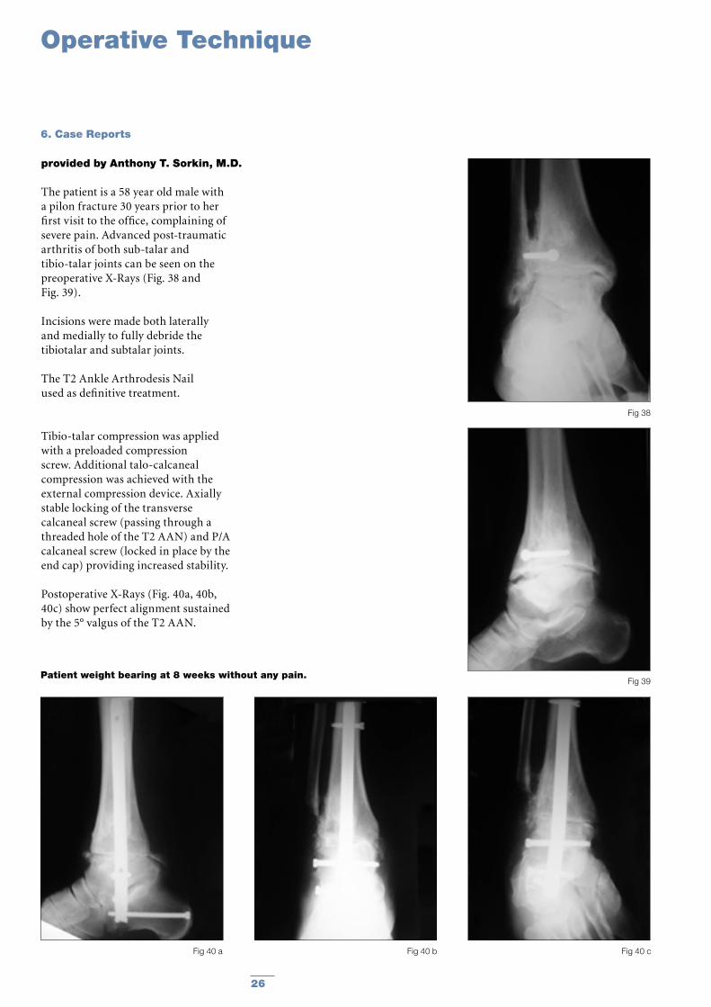
6. Case Reports
provided by Anthony T. Sorkin, M.D.
The patient is a 58 year old male with a pilon fracture 30 years prior to her first visit to the office, complaining of severe pain. Advanced post-traumatic arthritis of both sub-talar and tibio-talar joints can be seen on the preoperative X-Rays (Fig. 38 and Fig. 39).
Incisions were made both laterally and medially to fully debride the tibiotalar and subtalar joints.
The T2 Ankle Arthrodesis Nail used as definitive treatment.
Tibio-talar compression was applied with a preloaded compression screw. Additional talo-calcaneal compression was achieved with the external compression device. Axially stable locking of the transverse calcaneal screw (passing through a threaded hole of the T2 AAN) and P/A calcaneal screw (locked in place by the end cap) providing increased stability.
Postoperative X-Rays (Fig. 40a, 40b, 40c) show perfect alignment sustained by the 5° valgus of the T2 AAN.
Patient weight bearing at 8 weeks without any pain.
Fig 38
Fig 39
Fig 40 cFig 40 a Fig 40 b
26

References
7. References
1. Tibiotalocalcaneal fusion with a retrograde intramedullary nail: clinical and functional outcomes. Millett PJ, O‘Malley MJ, Tolo ET, Gallina J, Fealy S, Helfet DL. Harvard Medical School, Brigham & Women‘s Hospital, Boston, Massachusetts, USA. Am J Orthop. 2002 Sep; 31(9):531-6.
2. The effect of bone quality on the stability of ankle arthrodesis. A finite element study. Alonso-Vazquez A, Lauge-Pedersen H, Lidgren L, Taylor M. Bioengineering Sciences Research Group, School of Engineering Sciences, University of Southampton, Southampton SO17 1BJ, UK. Foot Ankle Int. 2004 Nov; 25(11):840-50.
3. Ankle arthrodesis with intramedullary compression nailing Muckley T, Schutz T, Srivastava S, Goebel M, Gonschorek O, Bühren V. Berufsgenossenschaftliche Unfallklinik, Murnau. Unfallchirurg.
2003 Sep; 106(9):732-40.
4. Realignment arthrodesis of the rearfoot and ankle: a comprehensive evaluation.
Mendicino RW, Lamm BM, Catanzariti AR, Statler TK, Paley D. Division of Foot and Ankle Surgery, Western Pennsylvania Hospital, Pittsburgh, PA 15224, USA.
5. Primary stiffness of different arthrodesis techniques for the upper ankle joint considering the compression nail: a biomechanical study
Muckley T, Eichhorn S, Steinhauser E, von Oldenburg G, Speitling A, Hofmann G.O., J. Ortop. Trauma 2004 #18,
6. Intramedullary nailing in tibiocalcaneal arthrodesis Goebel M, Muckley T, Gerdesmeyer L, Militz M, Bühren V. Unfallchirurg. 2003 Aug; 106(8):633-41
27
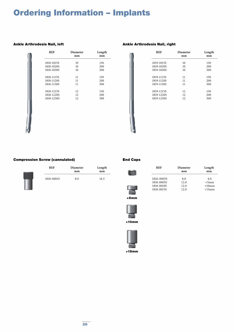
Ordering Information – Implants
Ankle Arthrodesis Nail, rightAnkle Arthrodesis Nail, left
REF Diameter Length mm mm
1818-1015S 10 1501818-1020S 10 2001818-1030S 10 300
1818-1115S 11 1501818-1120S 11 2001818-1130S 11 300
1818-1215S 12 1501818-1220S 12 2001818-1230S 12 300
End Caps
REF Diameter Length mm mm
1818-0001S 8.0 14.5
Compression Screw (cannulated)
REF Diameter Length mm mm
REF Diameter Length mm mm
1819-1015S 10 1501819-1020S 10 2001819-1030S 10 300
1819-1115S 11 1501819-1120S 11 2001819-1130S 11 300
1819-1215S 12 1501819-1220S 12 2001819-1230S 12 300
1826-0003S 8.0 4.01818-0005S 12.0 +5mm1818-0010S 12.0 +10mm1818-0015S 12.0 +15mm
+5mm
+10mm
+15mm
28
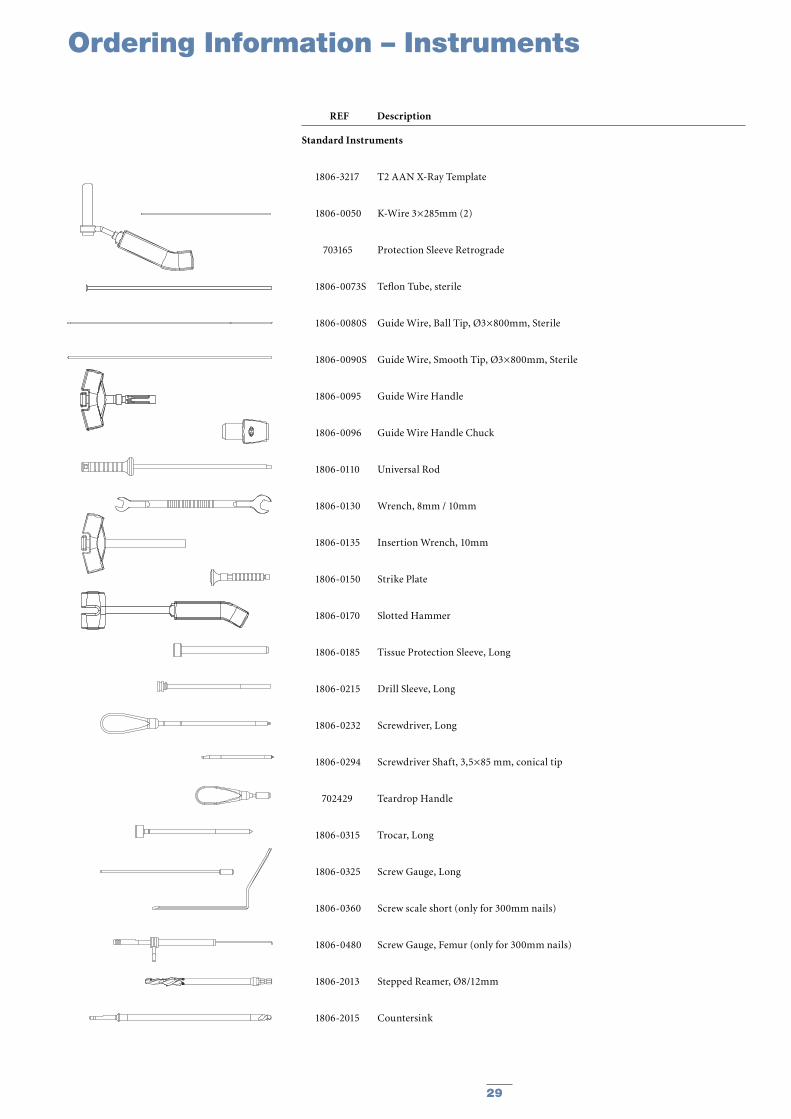
Ordering Information – Instruments
Standard Instruments
1806-3217 T2 AAN X-Ray Template
1806-0050 K-Wire 3×285mm (2)
703165 Protection Sleeve Retrograde
1806-0073S Teflon Tube, sterile
1806-0080S Guide Wire, Ball Tip, Ø3×800mm, Sterile
1806-0090S Guide Wire, Smooth Tip, Ø3×800mm, Sterile
1806-0095 Guide Wire Handle
1806-0096 Guide Wire Handle Chuck
1806-0110 Universal Rod
1806-0130 Wrench, 8mm / 10mm
1806-0135 Insertion Wrench, 10mm
1806-0150 Strike Plate
1806-0170 Slotted Hammer
1806-0185 Tissue Protection Sleeve, Long
1806-0215 Drill Sleeve, Long
1806-0232 Screwdriver, Long
1806-0294 Screwdriver Shaft, 3,5×85 mm, conical tip
702429 Teardrop Handle
1806-0315 Trocar, Long
1806-0325 Screw Gauge, Long
1806-0360 Screw scale short (only for 300mm nails)
1806-0480 Screw Gauge, Femur (only for 300mm nails)
1806-2013 Stepped Reamer, Ø8/12mm
1806-2015 Countersink
REF Description
29
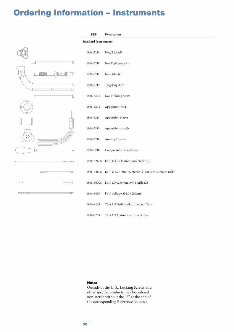
Standard Instruments
1806-3213 Nut, T2 AAN
1806-3218 Nut Tightening Pin
1806-3211 Nail Adapter
1806-3212 Targeting Arm
1806-3203 Nail Holding Screw
1806-3204 Apposition-ring
1806-3214 Apposition Sleeve
1806-3215 Apposition-handle
1806-3216 Aiming Adapter
1806-3210 Compression Screwdriver
1806-4260S Drill Ø4.2×340mm, AO, Sterile (2)
1806-4280S Drill Ø4.2×130mm, Sterile (2) (only for 300mm nails)
1806-5000S Drill Ø5×230mm, AO, Sterile (2)
1806-8018 Drill oblique, Ø4.2×250mm
1806-9263 T2 AAN Dedicated Instrument Tray
1806-9265 T2 AAN Add-on Instrument Tray
Ordering Information – Instruments
REF Description
Note:Outside of the U. S., Locking Screws and other specific products may be ordered non-sterile without the “S” at the end of the corresponding Reference Number.
30

Notes
31

The information presented in this brochure is intended to demonstrate a Stryker product. Always refer to the package insert, product label and/or user instructions before using any Stryker product. Surgeons must always rely on their own clinical judgment when deciding which products and techniques to use with their patients. Products may not be available in all markets. Product availability is subject to the regulatory or medical practices that govern individual markets. Please contact your Stryker representative if you have questions about the availability of Stryker products in your area.
Stryker Corporation or its subsidiary owns the registered trademark: Stryker Stryker Corporation or its subsidiary owns, uses or has applied for the following trademarks: T2
Literature Number: B1000044LOT B1606
Copyright © 2006 StrykerPrinted in Germany
Stryker Trauma GmbHProf.-Küntscher-Straße 1–5D - 24232 SchönkirchenGermanywww.osteosynthesis.stryker.com
Biologics
Surgical Products
Neuro & ENT
Trauma, Extremities & Deformities
Biologics
Surgical Products
Neuro & ENT
Trauma, Extremities & Deformities