t e s i s - dspace hometesis.ipn.mx/jspui/bitstream/123456789/6735/1/... · uno de los procesos...
TRANSCRIPT

INSTITUTO POLITÉCNICO NACIONAL ESCUELA SUPERIOR DE INGENIERIA MECANICA Y ELECTRICA UNIDAD PROFESIONAL “ADOLFO LÓPEZ MATEOS”
“CONTROL AUTOMÁTICO DE FLUJOS QUÍMICOS PARA EL
ACONDICIONAMIENTO DEL SECADOR YANKEE”
T E S I S
QUE PARA OBTENER EL TÍTULO DE:
INGENIERO EN CONTROL Y AUTOMATIZACIÓN
PRESENTAN: IVAN HERNÁNDEZ GARCÍA
JOSÉ LUIS HERNÁNDEZ PEREA
ASESORES:
M. EN C. PEDRO F. HUERTA GONZÁLEZ ING. JESÚS HERNÁNDEZ MUÑOZ
MÉXICO, D.F. 2010
ÍNDICE Objetivo General............................................................................................................................1 Objetivos Específicos.....................................................................................................................2 Introducción....................................................................................................................................3 CAPITULO I Marco Teórico...........................................................................................................4
1.1 Descripción general del proceso de fabricación de papel tissue.......................................5 1.1.1. Descripción del proceso de secado......................................................................10 1.1.2. Descripción del proceso de crepado....................................................................10 1.1.3. Descripción del proceso de acondicionamiento del secador Yankee.............. …12
1.2 Conceptos de crepado.......................................................................................................16
1.2.1. Definición de crepado...........................................................................................16 1.2.2. Geometría de crepado..........................................................................................18 1.2.3. Química del crepado.............................................................................................22
1.2.3.1. Características de químicos adhesivo, release, monofosfato...................22
1.3 Sistema Yankee Spray......................................................................................................24 1.3.1. Diseño de regadera Yankee Spray......................................................................24
1.3.1.1. Selección de espreas para regadera yankee spray.................................25 1.3.2. Cálculo de sólidos depositados en la superficie del secador yankee..................26
1.4 Definición de control automático……………………………………………………………...26 CAPITULO II Antecedentes.........................................................................................................28
2.1 Sistema Yankee spray actual...........................................................................................32 2.1.1 Dimensiones de regadera Yankee spray................................................................33
2.2 Planteamiento del problema, Filosofía de control............................................................34
2.2.1 Análisis del problema..............................................................................................34 2.2.2 Diagrama Porque-Porque (Causa - Raíz)..............................................................38
2.3 Justificación.......................................................................................................................39 2.3.1 Consecuencias en la producción............................................................................39
2.3.1.1 Pérdida por generación de merma...................................................................47

CAPITULO III Desarrollo (Propuesta de solución).....................................................................50
3.1 Diseño Propuesto de regadera Yankee..........................................................................51 3.2 Selección de Hardware.....................................................................................................52
3.2.1 Determinación de tipo de bombas..........................................................................54 3.2.2 Determinación de protocolo de comunicación........................................................56 3.2.3 Configuración de HMI.............................................................................................57 3.2.4 Fuente de alimentación..........................................................................................58 3.2.5 Gabinetes...............................................................................................................58 3.2.6 Conexiones.............................................................................................................59
3.3 Selección de Software......................................................................................................60 3.3.1 Configuración de comunicación..............................................................................60 3.3.2 Configuración de HMI............................................................................................ 60
3.4 Actividades para el Plan de Mantenimiento....................................................................60
CAPITULO IV Análisis Costo Beneficio.......................................................................................61
4. 1 Presupuesto..................................................................................................................62 4. 2 Análisis de Costos.........................................................................................................62 4. 3 Beneficios obtenidos.....................................................................................................62 4. 4 Rendimiento de la inversión ROI...................................................................................63
CAPITULO V Conclusiones.........................................................................................................64
5.1 Conclusiones.................................................................................................................65 5.2 Observaciones..............................................................................................................66
Fuentes de Consulta...................................................................................................................66 Anexos.........................................................................................................................................66

INGENIERÍA EN CONTROL Y AUTOMATIZACIÓN 1
Objetivo General. Controlar la dosificación de los flujos químicos: resina, release y monofosfato, para el recubrimiento de la superficie del secador yankee de la máquina de papel No. 3 de Planta Ecatepec Tissue de SCA México y Centroamérica S.A de C.V. por medio de bombas dosificadoras con señal de 4-20mA.
INGENIERÍA EN CONTROL Y AUTOMATIZACIÓN 2
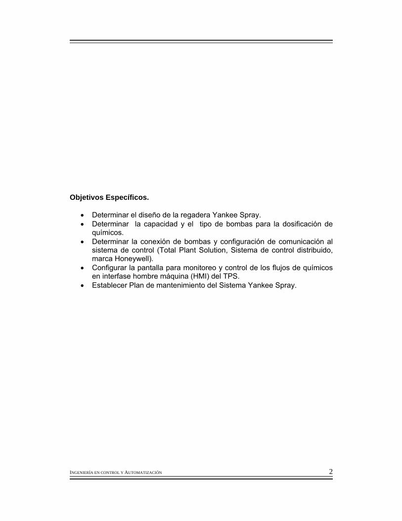
Objetivos Específicos.
• Determinar el diseño de la regadera Yankee Spray. • Determinar la capacidad y el tipo de bombas para la dosificación de
químicos. • Determinar la conexión de bombas y configuración de comunicación al
sistema de control (Total Plant Solution, Sistema de control distribuido, marca Honeywell).
• Configurar la pantalla para monitoreo y control de los flujos de químicos en interfase hombre máquina (HMI) del TPS.
• Establecer Plan de mantenimiento del Sistema Yankee Spray.
INGENIERÍA EN CONTROL Y AUTOMATIZACIÓN 3
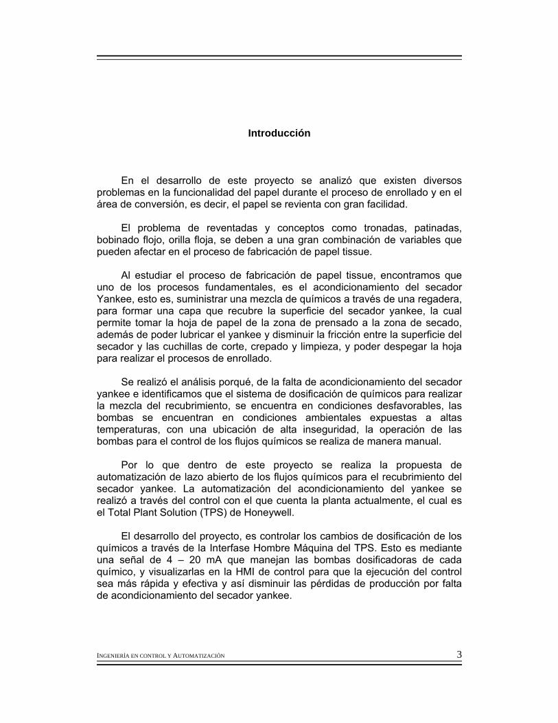
Introducción
En el desarrollo de este proyecto se analizó que existen diversos problemas en la funcionalidad del papel durante el proceso de enrollado y en el área de conversión, es decir, el papel se revienta con gran facilidad.
El problema de reventadas y conceptos como tronadas, patinadas,
bobinado flojo, orilla floja, se deben a una gran combinación de variables que pueden afectar en el proceso de fabricación de papel tissue.
Al estudiar el proceso de fabricación de papel tissue, encontramos que
uno de los procesos fundamentales, es el acondicionamiento del secador Yankee, esto es, suministrar una mezcla de químicos a través de una regadera, para formar una capa que recubre la superficie del secador yankee, la cual permite tomar la hoja de papel de la zona de prensado a la zona de secado, además de poder lubricar el yankee y disminuir la fricción entre la superficie del secador y las cuchillas de corte, crepado y limpieza, y poder despegar la hoja para realizar el procesos de enrollado.
Se realizó el análisis porqué, de la falta de acondicionamiento del secador
yankee e identificamos que el sistema de dosificación de químicos para realizar la mezcla del recubrimiento, se encuentra en condiciones desfavorables, las bombas se encuentran en condiciones ambientales expuestas a altas temperaturas, con una ubicación de alta inseguridad, la operación de las bombas para el control de los flujos químicos se realiza de manera manual.
Por lo que dentro de este proyecto se realiza la propuesta de
automatización de lazo abierto de los flujos químicos para el recubrimiento del secador yankee. La automatización del acondicionamiento del yankee se realizó a través del control con el que cuenta la planta actualmente, el cual es el Total Plant Solution (TPS) de Honeywell.
El desarrollo del proyecto, es controlar los cambios de dosificación de los
químicos a través de la Interfase Hombre Máquina del TPS. Esto es mediante una señal de 4 – 20 mA que manejan las bombas dosificadoras de cada químico, y visualizarlas en la HMI de control para que la ejecución del control sea más rápida y efectiva y así disminuir las pérdidas de producción por falta de acondicionamiento del secador yankee.

INGENIERÍA EN CONTROL Y AUTOMATIZACIÓN 4
INGENIERÍA EN CONTROL Y AUTOMATIZACIÓN 5
Capitulo I Marco Teórico.
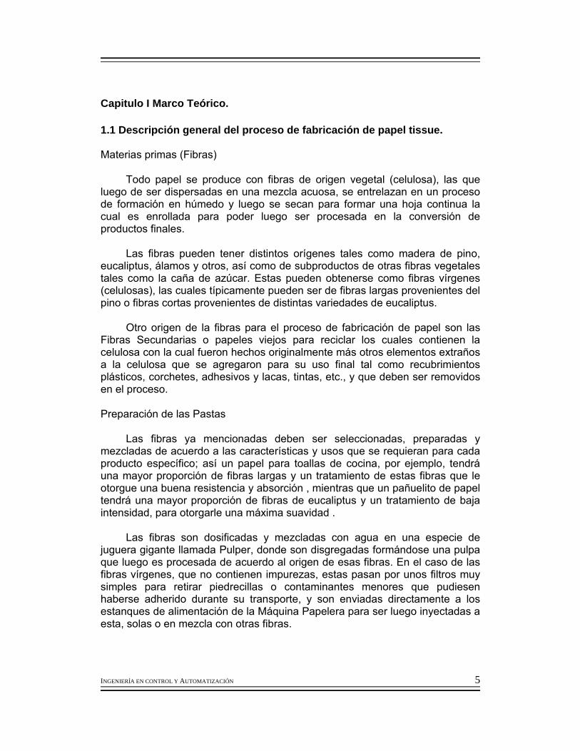
1.1 Descripción general del proceso de fabricación de papel tissue. Materias primas (Fibras)
Todo papel se produce con fibras de origen vegetal (celulosa), las que luego de ser dispersadas en una mezcla acuosa, se entrelazan en un proceso de formación en húmedo y luego se secan para formar una hoja continua la cual es enrollada para poder luego ser procesada en la conversión de productos finales.
Las fibras pueden tener distintos orígenes tales como madera de pino, eucaliptus, álamos y otros, así como de subproductos de otras fibras vegetales tales como la caña de azúcar. Estas pueden obtenerse como fibras vírgenes (celulosas), las cuales típicamente pueden ser de fibras largas provenientes del pino o fibras cortas provenientes de distintas variedades de eucaliptus.
Otro origen de la fibras para el proceso de fabricación de papel son las Fibras Secundarias o papeles viejos para reciclar los cuales contienen la celulosa con la cual fueron hechos originalmente más otros elementos extraños a la celulosa que se agregaron para su uso final tal como recubrimientos plásticos, corchetes, adhesivos y lacas, tintas, etc., y que deben ser removidos en el proceso.
Preparación de las Pastas
Las fibras ya mencionadas deben ser seleccionadas, preparadas y mezcladas de acuerdo a las características y usos que se requieran para cada producto específico; así un papel para toallas de cocina, por ejemplo, tendrá una mayor proporción de fibras largas y un tratamiento de estas fibras que le otorgue una buena resistencia y absorción , mientras que un pañuelito de papel tendrá una mayor proporción de fibras de eucaliptus y un tratamiento de baja intensidad, para otorgarle una máxima suavidad .
Las fibras son dosificadas y mezcladas con agua en una especie de juguera gigante llamada Pulper, donde son disgregadas formándose una pulpa que luego es procesada de acuerdo al origen de esas fibras. En el caso de las fibras vírgenes, que no contienen impurezas, estas pasan por unos filtros muy simples para retirar piedrecillas o contaminantes menores que pudiesen haberse adherido durante su transporte, y son enviadas directamente a los estanques de alimentación de la Máquina Papelera para ser luego inyectadas a esta, solas o en mezcla con otras fibras.

INGENIERÍA EN CONTROL Y AUTOMATIZACIÓN 6
En el caso de las Fibras Recicladas, luego de su disgregación en el pulper, estas son procesadas en distintos equipos y etapas para retirar las distintas impurezas o elementos extraños que acompañan a las fibras: depuración centrífuga para eliminar elementos pesados tales como clips, corchetes y arena ; depuración en coladores presurizados (perforaciones y ranuras de distintos tamaños) para eliminar trocitos y grumos de plásticos , adhesivos, etc.; lavado y flotación para eliminar tintas y cargas minerales .
Una vez que las fibras han sido depuradas de los elementos extraños, la pulpa o pasta, está en condiciones de ser alimentada sola o en mezcla, al proceso de fabricación del papel (máquina papelera).
Fabricación del Papel (Máquina Papelera)
En la máquina papelera se procesa la mezcla escogida de las pastas ya descritas y se transforma en un gran rollo de papel (“Jumbo Roll”); si bien los conceptos generales de las máquinas para distintos tipos de papeles son similares, una máquina papelera tissue tiene características especiales ya que debe producir papeles muy livianos y que sean “crepados” para otorgarles la flexiblidad, suavidad y absorción que requiere el producto final. Estas características se obtienen en la máquina con los siguientes procesos consecutivos y simultáneos:
• Formación : Consiste en inyectar la mezcla de agua y fibras (pasta ) sobre una o más mallas sin fin, en movimiento, donde gran parte del agua es retirada, dejando una trama de fibras que forman una hoja continua, pero todavía bastante húmeda.
• Prensado: La hoja húmeda es transferida, siempre en movimiento, a un paño (especie de alfombra sin fin), que la transporta hacia las prensas, que son rodillos perforados (1 o 2) los cuales presionan la hoja contra un enorme cilindro secador (Yankee), extrayéndole una gran cantidad de agua por este efecto.
• Secado: El secado final de la hoja se efectúa con esta adherida al cilindro secador (Yankee), como combinación del efecto del contacto con su superficie a mas de 100°C (el yankee es calentado internamente con vapor a presión), y del soplado por su otro lado de aire caliente a 500° C por una campana o capota envolvente que rodea al Yankee. Todo este proceso dura sólo un par de segundos ya que el papel viaja sobre el Yankee a una velocidad cercana a los 100 kilómetros por hora.
• Crepado y Enrollado: El crepado es un proceso clave para otorgar a la hoja de papel tissue características de flexibilidad, suavidad y absorción que la diferencian de los papeles lisos y consiste en micro arrugas a través de toda la hoja que se obtienen mediante una lámina “crepadora” que separa la hoja del Yankee en movimiento para que ésta quede libre para ser enrollada en la última parte de la máquina; como la enrolladora gira a una menor velocidad que el cilindro Yankee, la hoja tiende a permanecer contra la lámina, generándose así las arrugas o crepado. La hoja crepada es finalmente enrollada

INGENIERÍA EN CONTROL Y AUTOMATIZACIÓN 7
generándose una bobina de grandes dimensiones (típicamente de 2 metros de diámetro y 2 toneladas de peso) a la que se le denomina “Jumbo”.

INGENIERÍA EN CONTROL Y AUTOMATIZACIÓN 8
Figura 1.1 Diagrama General sobre el proceso de papel
INGENIERÍA EN CONTROL Y AUTOMATIZACIÓN 9
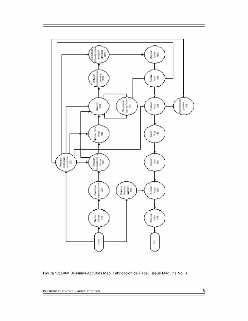
Figura 1.2 BAM Bussines Activities Map, Fabricación de Papel Tissue Máquina No. 3
INGENIERÍA EN CONTROL Y AUTOMATIZACIÓN 10
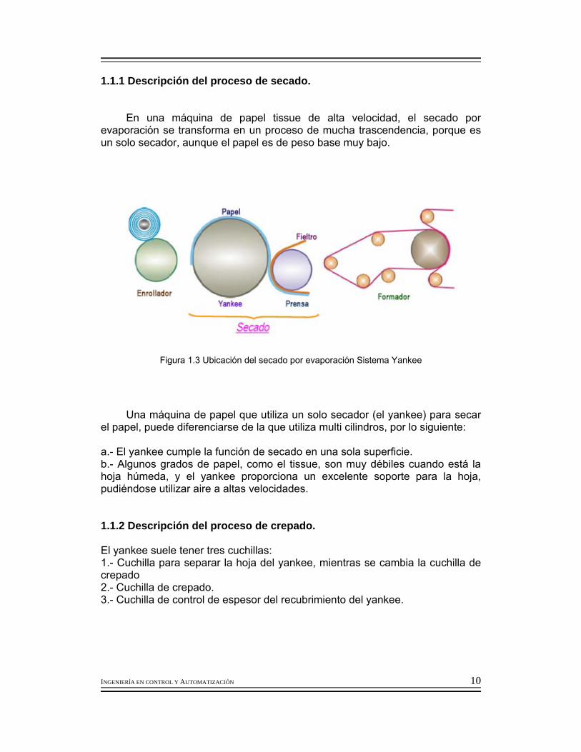
1.1.1 Descripción del proceso de secado.
En una máquina de papel tissue de alta velocidad, el secado por
evaporación se transforma en un proceso de mucha trascendencia, porque es un solo secador, aunque el papel es de peso base muy bajo.
Figura 1.3 Ubicación del secado por evaporación Sistema Yankee
Una máquina de papel que utiliza un solo secador (el yankee) para secar
el papel, puede diferenciarse de la que utiliza multi cilindros, por lo siguiente:
a.- El yankee cumple la función de secado en una sola superficie. b.- Algunos grados de papel, como el tissue, son muy débiles cuando está la hoja húmeda, y el yankee proporciona un excelente soporte para la hoja, pudiéndose utilizar aire a altas velocidades.
1.1.2 Descripción del proceso de crepado.
El yankee suele tener tres cuchillas: 1.- Cuchilla para separar la hoja del yankee, mientras se cambia la cuchilla de crepado 2.- Cuchilla de crepado. 3.- Cuchilla de control de espesor del recubrimiento del yankee.

INGENIERÍA EN CONTROL Y AUTOMATIZACIÓN 11
Figura 1.4 Ubicación de Cuchillas para el proceso de crepado
El crepado imparte una cantidad tremenda de energía mecánica sobre
la estructura de la hoja rompiendo y explotando los enlaces y arrugándose para dar las características de la hoja. Esta energía da calibre y suavidad.

INGENIERÍA EN CONTROL Y AUTOMATIZACIÓN 12
1.1.3 Descripción del proceso de acondicionamiento del secador Yankee.
Para que el yankee cumpla fielmente su cometido, es necesario que tenga una capa de recubrimiento sobre su superficie, para : a.- Evitar su deterioro. b.- Facilitar las labores que desarrollan sobre su superficie.
Figura 1.5 Imagen del Acondicionamiento la superficie del secador Yankee
INGENIERÍA EN CONTROL Y AUTOMATIZACIÓN 13
Influencia del recubrimiento del Yankee en las labores que se realizan sobre su superficie a.- Evita el desgaste acelerado de la cuchilla b.- Facilita la operación de crepado. Importancia de homogeneidad en el recubrimiento del yankee Para mantener una adhesión correcta de la hoja de papel en toda la superficie del yankee, para: a.- Una óptima calidad b.- Una óptima eficiencia en la operación de la máquina de papel.
En el proceso de acondicionamiento del Yankee se realiza la preparación de los químicos que son dosificados a través de una regadera para el recubrimiento de la superficie del secador Yankee.
Existen dos tipos de sistema de preparación de químicos para el
recubrimiento del secador yankee.

INGENIERÍA EN CONTROL Y AUTOMATIZACIÓN 14
FIGURA 1.6 Sistema de alimentación en línea
Sistema de Alimentación en líneaVentajas Desventajas
•Sistema cerrado limpio. • Poca o nula contaminación bacteriológica. •No hay contaminación de polvo. •Fácil mantenimiento.
•Recubrimiento no uniforme. •No es flexible. •Depende de la presión de la línea.
Equipo utilizado ampliamente papeles calidad media
TABLA 1.1 Tabla de ventajas y desventajas del sistema de alimentación en línea.
Yankee Dryer
Adhesi
Adhesi
Relea
Mill
140 Mill
Pressure Equalize
Mezcladores
Regulador de presión n Intercambiador de
presion
filtros
purg
Sistema de alimentación en línea

INGENIERÍA EN CONTROL Y AUTOMATIZACIÓN 15
FIGURA 1.7 Sistema de alimentación por tanque
Sistema de Alimentación con tanqueVentajas Desventajas
• Presión constante. • Flujo constante. • Recubrimiento uniforme. • Presión uniforme de regadera. • Flexible para cambios de concentración.
• Se ensucia con facilidad. • Puede formar microorganismos. • Tendencia alto costo de mantenimiento.
Se utiliza para grados de alta calidad y Premium.
TABLA 1.2 Tabla de ventajas y desventajas del sistema de alimentación por tanque
Yankee
Sistema de preparación con tanque
Modifie
r Relea
140 F vap
Intercambiador de calorr
filtros
Válvula de retorno
Flotador para control de Nivel de agua.
Linea de
3 bar or 40 PSI pressure
Control de presión

INGENIERÍA EN CONTROL Y AUTOMATIZACIÓN 16
1.2 Conceptos de crepado. 1.2.1 Definición de crepado.
El crepado aumenta la superficie específica del papel y abre las fibras,
permitiendo mayor capacidad de absorción y mayor flexibilidad que las de una hoja de papel corriente.
El conocimiento del crepado, es la llave para poder hacer negocios en la
industria del papel Tissue.
FIGURA 1.8 Función de la cuchilla de crepado
La función de la cuchilla de crepado es separar al papel de la superficie del yankee.

INGENIERÍA EN CONTROL Y AUTOMATIZACIÓN 17
FIGURA 1.9 Separación de la hoja de la superficie del secador
Otra función no menos importante es la de estructurar el crepado del papel tissue. Separación del papel de la superficie del secador
Para que la hoja de papel sea separada del yankee, es necesario que la
punta de la cuchilla venza las fuerzas que adhieren a la hoja a la superficie del secador yankee.
FIGURA 1.10 Acercamiento de la separación de la hoja del secador
INGENIERÍA EN CONTROL Y AUTOMATIZACIÓN 18
La carga que se tiene en la punta de la cuchilla debe de tener una fuerza
tal que envíe al papel fuera del cilindro yankee. Condiciones de operación de las cuchillas
La calidad del papel tissue es función de la geometría de la cuchilla, por ello para una calidad homogénea es necesario que esta condición permanezca constante.
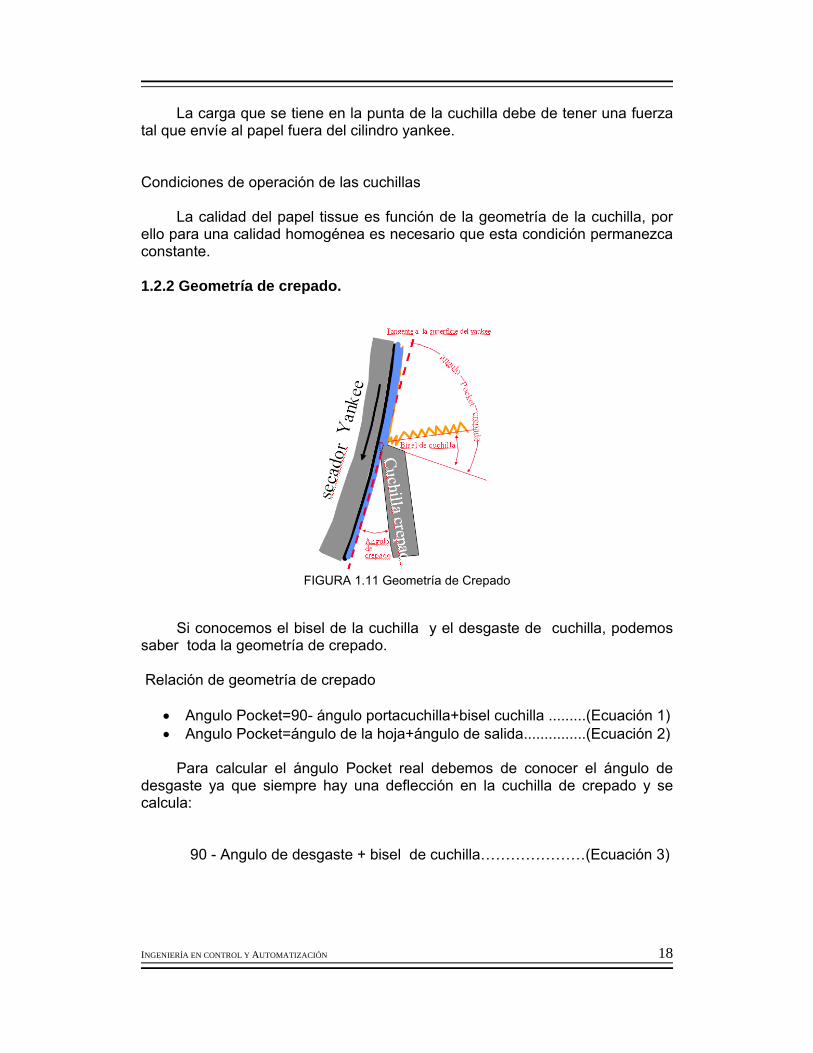
1.2.2 Geometría de crepado.
FIGURA 1.11 Geometría de Crepado
Si conocemos el bisel de la cuchilla y el desgaste de cuchilla, podemos saber toda la geometría de crepado. Relación de geometría de crepado
• Angulo Pocket=90- ángulo portacuchilla+bisel cuchilla .........(Ecuación 1) • Angulo Pocket=ángulo de la hoja+ángulo de salida...............(Ecuación 2)
Para calcular el ángulo Pocket real debemos de conocer el ángulo de
desgaste ya que siempre hay una deflección en la cuchilla de crepado y se calcula:
90 - Angulo de desgaste + bisel de cuchilla…………………(Ecuación 3)

INGENIERÍA EN CONTROL Y AUTOMATIZACIÓN 19
Con un ángulo alto de crepado se incrementa la posibilidad de romper los
enlaces de la fibra y de esta manera la suavidad se manifiesta en mayor grado, es decir, a mayor ángulo de bisel de la cuchilla se obtiene un mayor grado de suavidad del papel.
FIGURA 1.12 Ángulo al de crepado Consecuencia de un ángulo alto en la calidad del papel
Cuando el ángulo de la cuchilla de crepado es alto, se reduce el impacto de la hoja sobre la punta de la cuchilla, dando un crepado más fino.
En estas condiciones la suavidad del tissue se beneficia, debido a que se
rompen más las uniones de las fibras en la hoja debido al borde de la cuchilla. Teóricamente es muy fácil mantener una operación eficaz y constante
para la elaboración de un papel tissue de alta calidad. Las condiciones ideales son difíciles de manejar, pero sobre todo mantenerlas constantes y esto es el gran reto del productor de papel tissue.
Para mantener la calidad constante del papel tissue, es necesario que los
parámetros seleccionados también permanezcan constantes Deflección de la cuchilla
La acción de la cuchilla para levantar la hoja de la superficie del yankee
se modifica, y esto se hará más acentuado en la medida que el bisel de la punta de la cuchilla sea mayor.

INGENIERÍA EN CONTROL Y AUTOMATIZACIÓN 20
FIGURA 1.13 Estado de la cuchilla a mayor presión.
Este problema puede conducir a que la cuchilla pierda tanto su poder de separar la hoja del secador y esta logre pasar enrollándose en el yankee. El punto final de esto nos lleva al cambio de cuchilla.
El cambio de cuchilla va a estar en función de que la cuchilla soporte
más o menos tiempo de trabajo, pero lo real es que cada cambio de cuchilla el daño al yankee es más acentuado. El cambio de cuchilla de realiza con e l fin de conseguir una calidad deseada en el papel tissue.
Pero una cuchilla nueva tiene sus aspectos positivos pero también no
solo afecta la superficie del secador sino que puede también levantar el recubrimiento. Cuando la cuchilla no penetra lo suficiente en el recubrimiento puede ocurrir:
a.- La cuchilla rompe las fibras b.- Romperá la hoja ocasionando una caída de guía.

INGENIERÍA EN CONTROL Y AUTOMATIZACIÓN 21
FIGURA 1.14 Consecuencias de una mala penetración de la cuchilla en las fibras
El tener estos problemas, de operación, en donde una caída de guía lleva
a una pérdida de producción, la que es una pérdida económica, también adicionalmente acarreará efectos en la calidad del papel como por ejemplo en la resistencia a la tracción.
Si la cuchilla penetra muy profundamente en el recubrimiento, puede
ocurrir un daño a la superficie del yankee.
FIGURA 1.15 Consecuencias de una mala penetración de la cuchilla en la superficie del
secador

INGENIERÍA EN CONTROL Y AUTOMATIZACIÓN 22
1.2.3 Química del crepado. 1.2.3.1 Características de químicos adhesivo, release, monofosfato. 1. La preparación del recubrimiento para la superficie del secador yankee
tiene 3 componentes básicos, adhesivo, releases, y finos. 2. Algunas veces el recubrimiento incluye modificadores con bases
rehumectables. 3. El adhesivo o resina pega la hoja al secador, puede ser que reticule o
fílmico. 4. El release controla la adhesividad de la hoja al secador y lubrica a la
cuchilla crepadora. 5. Normalmente un recubrimiento (coating) contiene 50% de finos
Los químicos para el recubrimiento del yankee se pueden clasificar en naturales y sintéticos:
Los que se utilizan son los sintéticos, adhesivo resina, release y finos
como el monofosfato de amonio. Adhesivo, Resina
Las resinas reticulables, son las que tienen un punto en donde son más
adhesivos, sus propiedades son: Los primeros adhesivos fueron componentes naturales de la pulpa,
principalmente pitch y hemicelulosas. Más tarde se dieron cuenta que la adhesión de la hoja puede mejorar adicionando resinas en la pasta. Muchas plantas que producían toallas cafés sólo dependían de coating natural y de la resinas de resistencia en húmedo.
La mayoría de las resinas comerciales son de base polyamidas - epichlorohidrinas de resistencia en húmedo. Release Agente release o liberador. La mayoría es en base a hidrocarburos. Mezclado con un recubrimiento orgánico, puede ayudar a: a.- La dureza del recubrimiento. b.- El espesor del recubrimiento. c.- La adhesión de la hoja sobre el recubrimiento. d.- Provee una barrera lubricante entre el recubrimiento y la cuchilla, lo que alarga su vida útil. e.- Controla la adhesión de la hoja sobre el secador yankee f.- Controla el grosor del recubrimiento en le secador yankee

INGENIERÍA EN CONTROL Y AUTOMATIZACIÓN 23
FOSFATO MONO AMONICO
Esto formará una capa más dura ya que contribuye en los sólidos adicionados en el secador y evita la corrosión del secador.
Fases dinámicas de la formación del recubrimiento:
a.- Entrecruzado b.- Transición vítrea c.- Rehumedecimiento d.- Acoplamiento e.- Acción de la cuchilla f.- Curado total
Una combinación de un polímero con el agente release o liberador puede formar un recubrimiento dividido en tres regiones.
FIGURA 1.16 Capas formadas por el release

INGENIERÍA EN CONTROL Y AUTOMATIZACIÓN 24
1.3 Sistema Yankee Spray. 1.3.1 Diseño de regadera Yankee Spray.
FIGURA 1.17 Sistema Yankee-Spray
FIGURA 1.18 Regaderas para el acondicionamiento del secador (SYS) Factores para definir el diseño de la regadera Yankee Spray
• Distancia de regadera a la superficie del secador. • Presión de la regadera • Alimentación de coating • Temperatura del agua • Mantenimiento de boquillas • Desgaste de boquillas • Sistema de filtrado • Cobertura
?
Secado

INGENIERÍA EN CONTROL Y AUTOMATIZACIÓN 25
1.3.1.1 Selección de espreas para regadera yankee spray Geometría de la boquilla
FIGURA 1.18 Esquema de boquilla para regaderas
FIGURA 1.19 Vista lateral de regadera y boquilla
INGENIERÍA EN CONTROL Y AUTOMATIZACIÓN 26
Cálculos para diseño de regaderas: A partir de la boquilla seleccionada se decide el tipo de cobertura de la regadera. Datos: Ángulo de la boquilla = α Flujo de agua= GPM Fórmulas C= Distancia entre orificio de boquillas C=2Dtanα Cantidad de Boquillas a cobertura sencilla: N= Ancho de Máquina/Distancia entre centro……………….(Ecuación 4) Número de boquillas para una cobertura N N1= N*Cobertura………………………………………………..(Ecuación 5) Flujo de regadera total Consumo=N1*Flujo de agua…………………………………..(Ecuación 6) 1.3.2 Cálculo de sólidos depositados en la superficie del secador yankee.
Miligramos depositados en la superficie del secador Yankee mg=Flujo*sólidos del producto químico*1000/(Ancho Total*Velocidad de máquina)…………………………………………………………(Ecuación 7)

INGENIERÍA EN CONTROL Y AUTOMATIZACIÓN 27
INGENIERÍA EN CONTROL Y AUTOMATIZACIÓN 28
Capitulo II Antecedentes.
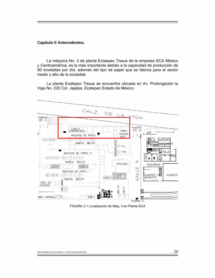
La máquina No. 3 de planta Ectaepec Tissue de la empresa SCA México y Centroamérica, es la más importante debido a la capacidad de producción de 90 toneladas por día, además del tipo de papel que se fabrica para el sector medio y alto de la sociedad.
La planta Ecatepec Tissue se encuentra ubicada en Av. Prolongación la
Viga No. 220 Col. Jajalpa, Ecatepec Estado de México.
FIGURA 2.1 Localización de Maq. 3 en Planta SCA

INGENIERÍA EN CONTROL Y AUTOMATIZACIÓN 29
Anteriormente la distribución de los químicos se encontraba de la siguiente manera.
FIGURA 2.2 Ubicación de químicos en la MAQ 3
En la figura 2.2 se muestra las condiciones de localización en la que se encontraban todos los tanques de almacenamiento de químicos necesarios para la fabricación del papel en la Maq. 3, solamente los que nos interesa son de los tres químicos utilizados para el acondicionamiento del Yankee los cuales son:
• RESINA • ACEITE RELEASE • MONOFOSFATO LIQUIDO
RESINA 03PV094 R. Y.
Aceite releaseccel 640-D R.Y.
TANQUE DE YANKEE SPRAY MONOFOSFATO LÍQUIDO
HIPOCLORITO
ANTIESPUMANTE 60403
RESINA KYMENE R. H.
GAS NAFTA
BLANCOPHOR R.
NALBRITE 2613
FLOT AID 638 CAT.
TRATAMIENTO MICRO B. BUSPERSE 2035 R. T.
BUSPERSE 46 A. S.
BUCKMAN 699 SUAVISANTE
ADHESIVO 513-064
TRATAMIENTO MICRO B.
TANQUE PREPARACIÓN COLOR NEGRO
INGENIERÍA EN CONTROL Y AUTOMATIZACIÓN 30
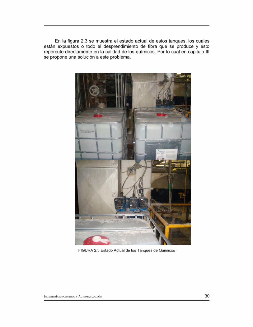
En la figura 2.3 se muestra el estado actual de estos tanques, los cuales están expuestos o todo el desprendimiento de fibra que se produce y esto repercute directamente en la calidad de los químicos. Por lo cual en capitulo III se propone una solución a este problema.
FIGURA 2.3 Estado Actual de los Tanques de Quimicos

INGENIERÍA EN CONTROL Y AUTOMATIZACIÓN 31
2.1 Sistema Yankee spray actual. Se utiliza un sistema de alimentación con tanque, el cual esta compuesto de la siguiente manera:
FIGURA 2.4 DTI Sistema Yankee Spray

INGENIERÍA EN CONTROL Y AUTOMATIZACIÓN 32
2.1.1 Dimensiones de regadera Yankee spray. Las dimensiones de la regadera Yankee spray se encuentran de la siguiente manera:
Dimensiones de regadera Yankee spray
1.- Distancia de la regadera con respecto a la superficie del secador Yankee 19” 2.- Número de espreas =25 y tipo de boquillas= 80030 3.- Cobertura, triple 4.- Flujo de consumo total= 3 gal/min 5.- Presión de regadera Yankee spray 120 psi 6.- Flujo de resina= 80 a 90 mL/min 7.- Flujo de release= 40 a 100 mL/min 8.- Flujo de monofosfato= 15 a 30 mL/min 9.- Nivel de Tanque de mezcla de sistema yankee spray =75% 10.- Temperatura de la mezcla en tanque =???
FIGURA 2.5 Sistema Yankee Spray Actual

INGENIERÍA EN CONTROL Y AUTOMATIZACIÓN 33
P=120psi Numero de espreas=25 Flujo=0.12gal/min Flujo Total=3.0 gal/min o 11.35 l/min Ángulo de aspersión=80° Diametro de orificio=0.021 Cobertura=triple Distancia de Cobertura=19.5” a 11 ¼ de separación del secador 2.2 Planteamiento del problema, Filosofía de control. 2.2.1 Análisis del problema
El recubrimiento del secador Yankee, como ya se ha mencionado es uno
de los factores fundamentales para la fabricación del papel tissue, ya que permite la función de “toma de hoja” de la zona de prensado al secador Yankee, interviene en el desarrollo de secado de la hoja de papel, permite el proceso de crepado y tiene la función de mantener en condiciones óptimas de lubricación y disminución de desgaste de la superficie del secador yankee.
Actualmente se tiene el sistema de alimentación con tanque del recubrimiento del secador yankee.
Los productos que se dosifican son: resina, release y monofosfato, a
través de bombas.
Dosificación de químicos
Producto químico Función Punto de
aplicaciónConsumo kg/día
maq1/maq2/maq3 Flujo ml/min
Acondicionamiento del Secador (Yankee)Monofosfato de Amonio
Antioxidante del Secador Secador 0.06/0.065/0.02 15-30
N-03PV094 Resina Secador Secador 1.7/0.7/1.5 70-80
N-640D Release Secador Secador 1/0.7/0.75 40-50
TABLA 2.1 Tabla de valores de dosificación de quimicos
INGENIERÍA EN CONTROL Y AUTOMATIZACIÓN 34
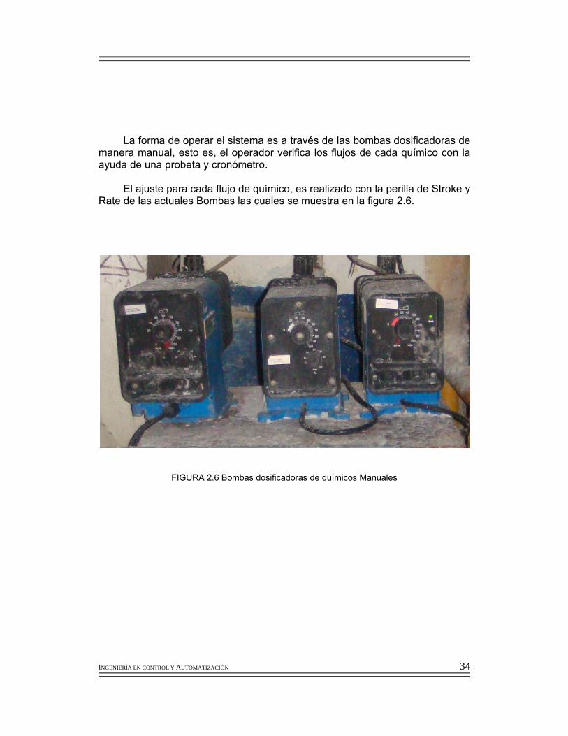
La forma de operar el sistema es a través de las bombas dosificadoras de
manera manual, esto es, el operador verifica los flujos de cada químico con la ayuda de una probeta y cronómetro.
El ajuste para cada flujo de químico, es realizado con la perilla de Stroke y
Rate de las actuales Bombas las cuales se muestra en la figura 2.6.
FIGURA 2.6 Bombas dosificadoras de químicos Manuales
INGENIERÍA EN CONTROL Y AUTOMATIZACIÓN 35

INGENIERÍA EN CONTROL Y AUTOMATIZACIÓN 36
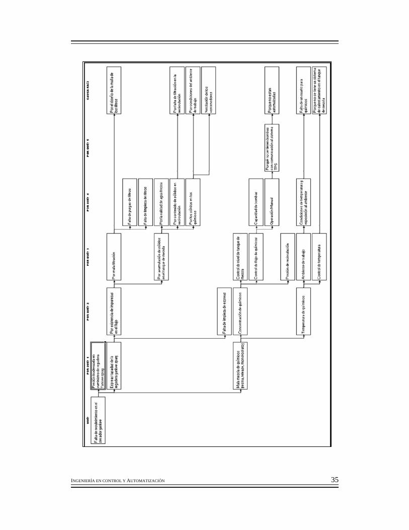
FIGURA 2.7 Diagrama PORQUE-PORQUE 2.2.2 Diagrama Porque-Porque (Causa - Raíz).
Se realiza el análisis para encontrar las causas raíz del problema
mediante la herramienta de 5 porqué´s. Se puede observar que existen diversos elementos que intervienen para
un buen desempeño del sistema de acondicionamiento del secador Yankee, tales como: 1.- Calidad de agua. 2.- Funcionalidad de filtración 3.- Condiciones de instalación de dosificación de químicos. 4.- Condiciones de seguridad y exposición al ambiente de las bombas.
La forma de operar el sistema Yankee spray, tiene alto riesgo por las
condiciones de instalación que se tiene tales como:
1.- Las tuberías de dosificación se encuentran colgantes por la estructura de la máquina. 2.- Los tanques no tienen una sección o lugar definido para su localización. 3.- Las bombas se encuentran sobre puestas en los contenedores de los químicos y expuestas a altas temperaturas ambientales. 4.- Las conexiones eléctricas se encuentran colgantes así como en un estado de inseguridad.
2.3 Justificación.
2.3.1 Consecuencias en la producción.
Debido a que no se tiene un control en automático el tiempo de respuesta para poder determinar el cambio y asegurar un ajuste en cualquiera de las variables de control, nos lleva a la generación de merma por papel poroso, tiempos perdidos por no poder despegar la hoja de papel del secador yankee, por defectos de calidad de la característica de elongación, por rasgado en cambio de cuchilla, por desgaste de la cuchilla.
Mediante el análisis de la información de tiempos pedidos y pérdidas en la
producción se realiza el histórico de Junio de 2008 a Septiembre del 2008.

INGENIERÍA EN CONTROL Y AUTOMATIZACIÓN 37
PARETO DE PERDIDAS "JUNIO 2008"
0
100
200
300
400
500
600
700
A B C D E F GCAUSAS DE FALLA
TIEM
PO (M
IN)
0.0%
10.0%
20.0%
30.0%
40.0%
50.0%
60.0%
70.0%
80.0%
90.0%
100.0%
% A
CU
M.
TIEMPO (MIN) % ACUM.
FIGURA 2.8 Diagrama de Pareto Junio 08

INGENIERÍA EN CONTROL Y AUTOMATIZACIÓN 38
FALLAS CLAVE No DE VECE
S
TIEMPO
(MIN)
TIEMPO
(HRS)
CAUSA
% ACUM.
% TOTA
L
LIMPIEZA GENERAL DE MÁQUINA A 88 621 10.35 O 24.1%24.1%
CAMBIO DE CUCHILLAS B 152 507 8.45 O 43.7%19.6%
REVENTADAS DE LA HOJA DE PAPEL C 42 475 7.92 O 62.1%18.4%
SE REALIZA LIMPIEZA CON GAS NAFTA A SECCIÓN TELA NO.2 POR IMPUREZAS (OPER) D 25 231 3.85 O 71.0% 8.9% CAMBIO DE FABRICACIÓN E 25 230 3.83 O 79.9% 8.9% CAMBIO DE ROLLOS F 13 113 1.88 O 84.3% 4.4%
DESACONDICIONAMIENTO DEL SECADOR G 4 70 1.17 O 87.0% 2.7%
VARIACIÓN DE FLUJO DE PASTA POR FALLA DE LA VALVULA (INST) H 3 70 1.17 M 89.7% 2.7%
SE REALIZA LIMPIEZA CON HIPOCLORITO A SECCIÓN FIELTRO (OPER) I 5 44 0.73 O 91.4% 1.7%
VARIACIÓN DE FLUJO DE PASTA (OPER) J 2 30 0.50 O 92.6% 1.2% BOTARSE QUEMADOR (ELE) K 2 30 0.50 M 93.8% 1.2% PAPEL CON FRANJAS HÚMEDAS L 1 30 0.50 O 94.9% 1.2% VARIACIÓN DE FLUJO DE PASTA POR FALLA DE LA VALVULA (INST) M 2 25 0.42 M 95.9% 1.0%
FALTA DE SUMINISTRO DE CONDENSADO (EXT) N 1 20 0.33 M 96.7% 0.8%
FALLA DE ACCIONAMIENTO DE LOS BRAZOS DE CARGA (ELE) O 2 15 0.25 M 97.3% 0.6% PAPEL CON ARRUGA POR FIELTRO TAPADO EN LAS ORILLAS (OPER) P 1 15 0.25 O 97.8% 0.6% PARA QUEMADORES PARA RESTABLECER GRÚA DE 10 TON. (ELE) Q 1 10 0.17 M 98.2% 0.4% ATASCARSE QUEMADORRES DESPUES DE METERLOS EN SERVICIO (OPER) R 1 10 0.17 O 98.6% 0.4%
VARIACIÓN DE FLUJO DE RELEASE (OPER) S 1 10 0.17 O 99.0% 0.4%
CAMBIO DE BOMBA DE RELEASE (OPER) T 1 10 0.17 O 99.4% 0.4%
BOTARSE REFINADOR (ELE) U 1 10 0.17 M 99.8% 0.4% MERMA POR MUESTRAS V 1 3 0.05 O 99.9% 0.1%
ACUMULACIÓN DE PASTA EN EL RODILLO TENSOR (OPER) W 1 3 0.05 O 100.0
% 0.1%
ACUMULADO POR DIA (MIN)
TOTAL 375 2582 43.03 100% 100%
ACUMULADO POR DIA (HR)
TOTAL 375 43.03 43.03 100% 100%
TABLA 2.1 Tabla de fallas del mes de Junio 08

INGENIERÍA EN CONTROL Y AUTOMATIZACIÓN 39
PARETO DE PERDIDAS "JULIO 2008"
0
100
200
300
400
500
600
700
A B C D E F G H I J K L M N O P Q R SCAUSAS DE FALLA
TIEM
PO (M
IN)
0.0%
10.0%
20.0%
30.0%
40.0%
50.0%
60.0%
70.0%
80.0%
90.0%
100.0%
% A
CU
M.
TIEMPO (MIN) % ACUM.
FIGURA 2.9 Diagrama de Pareto de Julio 08

INGENIERÍA EN CONTROL Y AUTOMATIZACIÓN 40
TABLA 2.2 Tabla de fallas de Julio 08
FALLAS CLAVE No DE VECES
TIEMPO (MIN)
TIEMPO (HRS)
CAUSA % ACUM.
% TOTAL
LIMPIEZA GENERAL DE MÁQUINA A 101 578 9.63 O 25.3% 25.3%
CAMBIO DE CUCHILLAS B 164 431 7.18 O 44.2% 18.9%
REVENTADAS DE LA HOJA DE PAPEL C 33 268 4.47 O 55.9% 11.7%
SE REALIZA LIMPIEZA CON GAS NAFTA A SECCIÓN TELA NO.2 POR IMPUREZAS (OPER) D 28 234 3.90 O 66.2% 10.2%CAMBIO DE FABRICACIÓN E 40 181 3.02 O 74.1% 7.9%
VARIACIÓN DE FLUJO DE PASTA POR FALLA DE LA VALVULA (INST) F 4 92 1.53 M 78.1% 4.0%
MALA TRANSFERENCIA DE LA HOJA DE PAPEL DEL FIELTRO AL SECADOR YANKEE (OPER) G 2 80 1.33 O 81.6% 3.5% CAMBIO DE ROLLOS H 5 61 1.02 O 84.3% 2.7%
SE REALIZA LIMPIEZA CON HIPOCLORITO A SECCIÓN FIELTRO (OPER) I 5 60 1.00 O 86.9% 2.6%
DESCONECTAR CABLES DE CONTROL DE GRÚA (ELE) J 2 60 1.00 M 89.5% 2.6%
PRUEBA DE PROCESO OCASIONA CARGAS BAJAS (OPER) K 1 50 0.83 O 91.7% 2.2%
SOBRECALENTAMIENTO DEL SECADOR L 2 45 0.75 O 93.7% 2.0% SE REALIZA LIMPIEZA CON SOSA CAUSTICA A SECCIÓN FIELTRO (OPER) M 2 30 0.50 O 95.0% 1.3%
FALLA DE ACCIONAMIENTO DE LOS BRAZOS PRIMARIOS (ELE) N 1 27 0.45 M 96.2% 1.2%
DESACONDICIONAMIENTO DEL SECADOR O 2 25 0.42 O 97.3% 1.1%
APAGARSE FUEGO ALTO DEL QUEMADOR (ELE) P 1 25 0.42 M 98.4% 1.1%
ATORARSE CABLE CON ESTRACTOR DE MANDRILES (ELE) Q 1 20 0.33 M 99.3% 0.9%
BOTARSE ALUMBRADO DE TODA LA NAVE (ELE) R 1 10 0.17 M 99.7% 0.4%
REPARAR FILTRO DE UN HUIZACHE (MEC) S 1 7 0.12 M 100.0% 0.3% ACUMULADO POR DIA (MIN) TOTAL 396 2284 38.07 100% 100%ACUMULADO POR DIA (HR) TOTAL 396 38.07 38.07 100% 100%

INGENIERÍA EN CONTROL Y AUTOMATIZACIÓN 41
PARETO DE PERDIDAS "AGOSTO 2008"
0
100
200
300
400
500
600
700
A B C D E F G H I J K L M N O P Q RCAUSAS DE FALLA
TIEM
PO (M
IN)
0.0%
10.0%
20.0%
30.0%
40.0%
50.0%
60.0%
70.0%
80.0%
90.0%
100.0%
% A
CU
M.
TIEMPO (MIN) % ACUM.
FIGURA 2.10 Diagrama de Pareto de Agosto 08

INGENIERÍA EN CONTROL Y AUTOMATIZACIÓN 42
FALLAS CLAVE No DE VECE
S
TIEMPO
(MIN)
TIEMPO
(HRS)
CAUSA
% ACUM.
% TOTA
L
LIMPIEZA GENERAL DE MÁQUINA A 117 652 10.87 O 26.4%26.4%
CAMBIO DE CUCHILLAS B 196 539 8.98 O 48.2%21.8%
REVENTADAS DE LA HOJA DE PAPEL C 36 356 5.93 O 62.6%14.4%
SE REALIZA LIMPIEZA CON GAS NAFTA A SECCIÓN TELA NO.2 POR IMPUREZAS (OPER) D 24 304 5.07 O 74.8%
12.3%
CAMBIO DE FABRICACIÓN E 45 179 2.98 O 82.1% 7.2%
FALTA DE REDUCTOR DE BRAZOS PRIMARIOS, DAÑARSE CUÑA DEL COPLE (MEC) F 1 88 1.47 M 85.6% 3.6%
SE REALIZA LIMPIEZA CON HIPOCLORITO A SECCIÓN FIELTRO (OPER) G 5 72 1.20 O 88.6% 2.9%
VARIACIÓN DE FLUJO DE PASTA POR FALLA DE LA VALVULA (INST) H 4 60 1.00 M 91.0% 2.4%
DESACONDICIONAMIENTO DEL SECADOR I 3 60 1.00 O 93.4% 2.4%MALA TRANSFERENCIA DE LA HOJA DE PAPEL DEL FIELTRO AL SECADOR YANKEE (OPER) J 2 35 0.58 O 94.8% 1.4%CAMBIO DE ROLLOS K 3 25 0.42 O 95.8% 1.0%
DAÑARSE MOTOR DE BOMBA DE VACÍO (ELE) L 1 20 0.33 M 96.6% 0.8%
HUMEDAD ALTA POR FALLA DEL EQUIPO DE MEDICIÓN (OPER) M 1 20 0.33 O 97.5% 0.8%
CAMBIO DE HUIZACHE DE CORTE POR TAPARSE (OPER) N 2 19 0.32 O 98.2% 0.8%
SE REALIZA LIMPIEZA CON GAS NAFTA A SECCIÓN TELA NO.1 POR IMPUREZAS (OPER) O 2 14 0.23 O 98.8% 0.6%
BOTARSE BOMBA DE VACÍO NO.4 A CAJAS DEL FIELTRO (ELE) P 1 10 0.17 M 99.2% 0.4%
BOTARSE QUEMADOR LADO HUMEDO (ELE) Q 1 10 0.17 M 99.6% 0.4%
FALLA DE ACCIONAMIENTO DE BRAZOS PRIMARIOS (ELE) R 1 10 0.17 M 100.0
% 0.4%
ACUMULADO POR DIA (MIN)
TOTAL 445 2473 41.22 100% 100%
ACUMULADO POR DIA (HR)
TOTAL 445 41.22 41.22 100% 100%
TABLA 2.3 Tabla de fallas de Agosto 08

INGENIERÍA EN CONTROL Y AUTOMATIZACIÓN 43
FIGURA 2.11 Diagrama de Pareto de Septiembre 08

INGENIERÍA EN CONTROL Y AUTOMATIZACIÓN 44
FALLAS CLAVENo DE
VECES
TIEMPO
(MIN)
TIEMPO
(HRS)
CAUSA
% ACUM.
% TOTA
L
LIMPIEZA GENERAL DE MÁQUINA A 137 794 13.23 O 31.3%31.3%
CAMBIO DE CUCHILLAS B 239 626 10.43 O 55.9%24.7%
REVENTADAS DE LA HOJA DE PAPEL C 41 340 5.67 O 69.3%13.4%
CAMBIO DE FABRICACIÓN D 30 228 3.80 O 78.3% 9.0%
DESACONDICIONAMIENTO DEL SECADOR E 5 107 1.78 O 82.5% 4.2%
SE REALIZA LIMPIEZA CON HIPOCLORITO A SECCIÓN FIELTRO (OPER) F 4 85 1.42 O 85.9% 3.3%CAMBIO DE ROLLOS G 3 60 1.00 O 88.2% 2.4%
SE REALIZA LIMPIEZA CON GAS NAFTA A SECCIÓN TELA NO.2 POR IMPUREZAS (OPER) H 4 55 0.92 O 90.4% 2.2%
ATASCARSE BOMBA HIDRAULICA DE TOLVA DE HIDRAPULPER DE FIBRA LARGA (MEC) I 1 35 0.58 M 91.8% 1.4%
BOTARSE BOMBAS DE VACÍO (ELE) J 1 35 0.58 M 93.1% 1.4%BOTARSE QUEMADOR (ELE) K 3 32 0.53 M 94.4% 1.3%
ACONDICIONAMIENTO POR ARRANQUE DE MÁQUINA (OPER) L 1 25 0.42 O 95.4% 1.0%
AONDICIONAMIENTO DE FIELTRO (OPER) M 2 20 0.33 O 96.2% 0.8%
HUMEDAD ALTA (OPER) N 1 20 0.33 O 97.0% 0.8%
AJUSTE DE CUCHILLAS DE CREPADO POR PROBLEMAS DE DESPEGUE DE LA HOJA DEL SECADOR (MEC) O 1 17 0.28 M 97.6% 0.7%
MALA TRANSFERENCIA DE LA HOJA DE PAPEL DEL FIELTRO AL SECADOR YANKEE (OPER) P 1 15 0.25 O 98.2% 0.6%
VARIACIÓN DE FLUJO DE PASTA POR FALLA DE LA VALVULA (INST) Q 1 15 0.25 M 98.8% 0.6%
ATORARSE BRAZOS PRIMARIOS (MEC) R 1 15 0.25 M 99.4% 0.6%
RESISTENCIAS BAJAS POR AJUSTE DE DISCOS DEL REFINADOR (OPER) S 1 10 0.17 O 99.8% 0.4%
VARIACIÓN DE FLUJO DE PASTA POR FALLA DE LA VALVULA (OPER) T 1 5 0.08 O 100.0
% 0.2%
ACUMULADO POR DIA (MIN)
TOTAL 478 2539 42.32 100% 100%
ACUMULADO POR DIA (HR)
TOTAL 478 42.32 42.32 100% 100%
TABLA 2.4 Tabla de fallas de Septiembre 08

INGENIERÍA EN CONTROL Y AUTOMATIZACIÓN 45
2.3.1.1 Pérdida por generación de merma
Podemos observar que el desacondicionamiento del secador en los paretos,
es una causa que no tiene alto impacto, sin embargo al analizar porqué se presentan reventadas de hoja y porque se presentan en esa frecuencia el cambio de cuchillas. Se llegó a la conclusión que el correcto acondicionamiento del secador influye en gran medida al proceso del secado del papel y a la separación de la hoja de papel del secador.
El correcto acondicionamiento del secador influye en gran medida sobre la
frecuencia con la que se debe realizar el cambio de cuchillas debido a que el acondicionamiento del secador también realiza la función de lubricante entre la superficie del secador y el filo de la cuchilla, ya que no hay que olvidar que son dos metales sometidos a una fuerza de fricción.
Cuando el operador se ve en necesidad de realizar un cambio de cuchillas,
no es factible realizar un paro temporal de la maquina para realizarlo y tampoco es factible omitir esta acción. Por lo cual en el momento que se realiza el cambio de cuchillas, es necesario, realizar un ajuste en la cuchilla de limpieza para que despegue todo el papel de la superficie del secador, pero este papel se pierde, en pocas palabras se convierte en merma y por mas que el operario lo haga en el menor tiempo posible se genera perdida por merma. Por esta razón es necesario bajar la frecuencia con la que se realiza este cambio.
En la siguiente figura se muestra la grafica referente a la generación de
merma de los meses Julio, Agosto y Septiembre.

INGENIERÍA EN CONTROL Y AUTOMATIZACIÓN 46
FIGURA 2.12 Diagrama de Pareto Comparativo Julio-Septiembre

INGENIERÍA EN CONTROL Y AUTOMATIZACIÓN 47
En resumen de las pérdidas más importantes y considerando una afectación del 10% de las principales causas por falta de acondicionamiento tenemos la siguiente tabla:
Concepto Unidades Junio Julio Agosto SeptiembreTiempo por desacondicionamiento min 70 25 60 10710% de tiempo por cambio de cuchillas min 51 43 54 6210% de tiempo por reventadas min 48 27 36 34Tiempo total min 169 95 150 203Ancho útil m 3.3 3.3 3.3 3.3Velocidad de la máquina m/min 1550 1550 1550 1550Gramaje del papel Kg 0.0155 0.0155 0.0155 0.0155Producción total Kg 13398.7425 7531.8375 11892.375 16094.3475
Ton 13.3987425 7.5318375 11.892375 16.0943475
Costo por tonelada MNX 10,752.56 10,619.47 10,654.92 10,654.92 Costo total pérdida MNX 144070.721 79984.1348 126712.304 171483.985
Merma rechazada por calidad15% de jumbos por papel picado Ton 0.325 0.55 0.86Rasgado por cuchilla Ton 0.308 0.5 0.5610% de jumbos con reventadas Ton 1.4 1.12 1.97Total Ton 0 2.033 2.17 3.39
Costo de merma MNX 2500 2500 2500 2500Costo total por merma MNX 0 5082.5 5425 8475
Total MNX 144070.721 85066.6348 132137.304 179958.985Total Acumulado MNX 144070.721 229137.356 361274.66 541233.646
Histórico 2008
TABLA 2.5 Tabla de Históricos Junio-Septiembre 08

INGENIERÍA EN CONTROL Y AUTOMATIZACIÓN 48
INGENIERÍA EN CONTROL Y AUTOMATIZACIÓN 49
Capitulo III Desarrollo (Propuesta de solución). La propuesta de solución es:
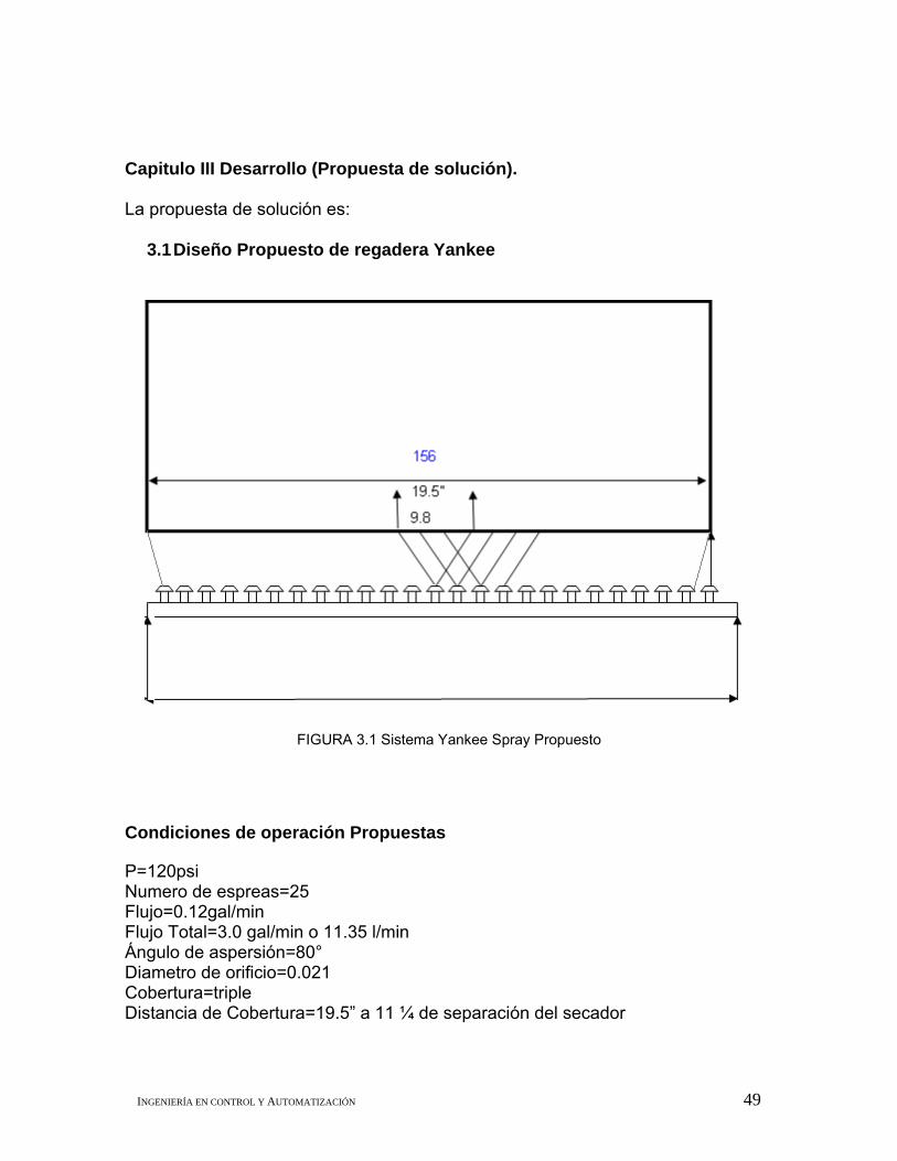
3.1 Diseño Propuesto de regadera Yankee
FIGURA 3.1 Sistema Yankee Spray Propuesto
Condiciones de operación Propuestas P=120psi Numero de espreas=25 Flujo=0.12gal/min Flujo Total=3.0 gal/min o 11.35 l/min Ángulo de aspersión=80° Diametro de orificio=0.021 Cobertura=triple Distancia de Cobertura=19.5” a 11 ¼ de separación del secador

INGENIERÍA EN CONTROL Y AUTOMATIZACIÓN 50
3.2 Selección de Hardware. 3.2.1 Determinación de tipo de bombas.
Se instalará bombas con comunicación al sistema de control distribuido TPS,
para monitoreo y control en lazo abierto del flujo de los químicos para el recubrimiento del secador yankee.
Se realizará la instalación de las bombas en gabinetes Se colocaran los contenedores de los químicos en un área de condiciones
reguladas con seguridad.
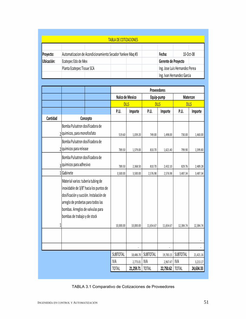
El tipo de bombas que se determinaron usar para este proyecto son de la marca PULSATRON, después de validar otras opciones Técnico-Comerciales las cuales se muestran en a continuación.
INGENIERÍA EN CONTROL Y AUTOMATIZACIÓN 51
TABLA 3.1 Comparativo de Cotizaciones de Proveedores
Proyecto: Automatizacion de Acondicionamiento Secador Yankee Maq #3 Fecha:Ubicación: Ecatepec Edo de Mex Gerente de Proyecto
Planta Ecatepec Tissue SCA
P.U. Importe P.U. Importe P.U. ImporteCantidad
2 519.60 1,039.20 749.00 1,498.00 730.00 1,460.00
2 789.50 1,579.00 810.70 1,621.40 799.90 1,599.80
3 789.50 2,368.50 810.70 2,432.10 829.76 2,489.28
1 3,500.00 3,500.00 2,576.98 2,576.98 3,487.34 3,487.34
‐
‐ ‐ ‐
SUBTOTAL 18,486.70 SUBTOTAL 19,783.15 SUBTOTAL 21,421.16
IVA 2,773.01 IVA 2,967.47 IVA 3,213.17
TOTAL 21,259.71 TOTAL 22,750.62 TOTAL 24,634.33
Bomba Pulsatron dosificadora de quimicos para adhesivo
DLLS DLLS
TABLA DE COTIZACIONES
Bomba Pulsatron dosificadora de quimicos, para monofosfato
Bomba Pulsatron dosificadora de quimicos para release
1
ProveedoresNalco de Mexico Equip‐pump Matercon
12,384.74
DLLS
Gabinete
Concepto
Ing. Jose Luis Hernandez PereaIng. Ivan Hernandez Garcia
10‐Oct‐08
Material varios: tuberia tubing de inoxidable de 3/8" hacia los puntos de dosificación y succión. Instalación de arreglo de probetas para todos las bombas. Arreglos de valvulas para bombas de trabajo y de stock 10,000.00 10,000.00 11,654.67 11,654.67 12,384.74

INGENIERÍA EN CONTROL Y AUTOMATIZACIÓN 52
La selección de bombas se realiza mediante la capacidad que debe tener la
bomba de dosificar los flujos determinados de cada químico. La siguiente tabla nos permite seleccionar el modelo de la bomba de acuerdo
a los requerimientos establecidos. MODELO
LPA3MAPTC1500 , LPG4MAPTC1500
FIGURA 3.2 Bomba Dosificadora Serie MP
La razón por la cual se tomó la decisión de utilizar estas bombas
dosificadoras de flujo es debido a que actualmente ya se manejan unas bombas de control manual de esta marca, por lo cual se estaría adquiriendo una misma marca para este tipo de equipo , lo cual será de mayor conveniencia ya que se podría manejar a un mismo proveedor para la compra de refacciones o garantía de equipo e instalación. Esto con el sentido de poder eficientar el tiempo de los trámites administrativos. Debido a la capacidad de cada bomba se determina el tipo y queda de la siguiente manera: CANTIDAD MODELO DESCRIPCION
1 LPA3MAPTC1500 BOMBA DOSIFICADORA PARA MONOFOSFATO3 LPG4MAPTC1500 BOMBA DOSIFICADORA PARA ADHESIVO, RELEASE y RESPALDO
TABLA 3.2 Tabla Modelos y Aplicaciones de bombas dosificadoras. La siguiente tabla contiene las especificaciones de cada una de las bombas a utilizar.

INGENIERÍA EN CONTROL Y AUTOMATIZACIÓN 53
TABLA 3.3 Especificaciones de Bombas

INGENIERÍA EN CONTROL Y AUTOMATIZACIÓN 54
3.2.2 Determinación de protocolo de comunicación. En este diagrama se presenta la arquitectura que tiene el Sistema de control actual, Total Plant Solution (TPS).
FIGURA 3.3 Arquitectura de Toptal Plant Solution (TPS)
Las Bombas dosificadoras se comunicaron de 4-20mA hacia la HPM del centro de control existente en la planta para la Máquina 3, del HPM se comunica con las estaciones de monitoreo y estaciones de ingeniería por medio de Ethernet como se muestra en la figura 3.3 con el cual se realizó la configuración del HMI que en este caso se dio de alta solamente un grupo especialmente para el proceso del acondicionamiento del Yankee.
Para este proyecto la razón por la cual no se cotizo tarjetas analógicas adicionales para la realización del monitoreo y control del proceso de acondicionamiento es porque el TPS contaba con la capacidad de agregar más elementos a sus tarjetas analógicas y posteriormente para la realización de futuros lazos de control.

INGENIERÍA EN CONTROL Y AUTOMATIZACIÓN 55
3.2.3 Configuración de HMI. La configuración de la interfaz hombre máquina se realiza mediante la estación de ingeniería, la cual se explica de la siguiente manera: 1.- Se selecciona la estación de ingeniería.
FIGURA 3.4 Pantalla de Configuración GUS
2.- Se configuran los tres elementos de acuerdo a los números de tarjeta y posición de entrada colocada.
FIGURA 3.5. Pantalla de Configuración II GUS

INGENIERÍA EN CONTROL Y AUTOMATIZACIÓN 56
3.- Se da propiedades de entrada y salida para realizar los ajustes de escalado de acuerdo a la señal analógica de 4 a 20 mA.
FIGURA 3.6. Pantalla de Configuración III GUS
4.- Se guardan y se descargan los cambios, con lo cual tenemos una respuesta como se muestra en la siguiente figura.
FIGURA 3.7. Pantalla Respuesta GUS
3.2.4 Fuente de alimentación. Debido a que sólo es la integración de las bombas dosificadoras al TPS, se cuenta con la fuente de alimentación del sistema. La fuente de alimentación de las bombas es de 115V. 3.2.5 Gabinetes. Se selecciona el gabinete de acero inoxidable para colocar las 4 bombas, 3 de dosificación en tiempo real y una bomba para respaldo en caso de falla.
INGENIERÍA EN CONTROL Y AUTOMATIZACIÓN 57
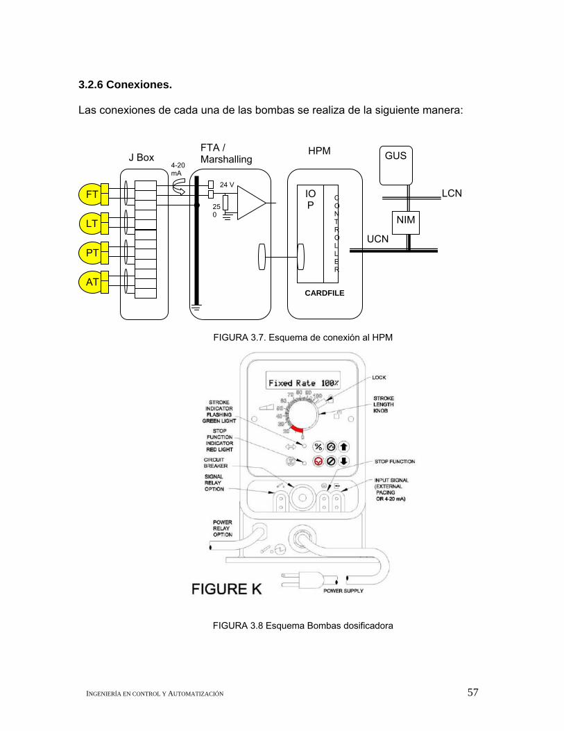
3.2.6 Conexiones.
Las conexiones de cada una de las bombas se realiza de la siguiente manera:
FIGURA 3.7. Esquema de conexión al HPM
FIGURA 3.8 Esquema Bombas dosificadora
FT
PT
AT
LT
24 V
250
4-20 mA
J Box FTA / Marshalling
IOP
CONTROLLER
HPM
NIM
UCN
GUS
LCN
CARDFILE

INGENIERÍA EN CONTROL Y AUTOMATIZACIÓN 58
3.3 Selección de Software. 3.3.1 Configuración de comunicación.
• Los instrumentos (4-20 mA) son conectados al HPM (APM, PM). • Los algoritmos de “control” residen en los procesadores del HPM. • Aplicaciones Complejas residen en el APP node.
3.3.2 Configuración de HMI.
• Las estaciones de trabajo (GUS) leen/escriben data en tiempo real desde los HPM.
• Los históricos son almacenados en el PHD (Oracle), utilizados para tendencias y registro de alarmas
3.4 Actividades para el plan de mantenimiento

INGENIERÍA EN CONTROL Y AUTOMATIZACIÓN 59
INGENIERÍA EN CONTROL Y AUTOMATIZACIÓN 60
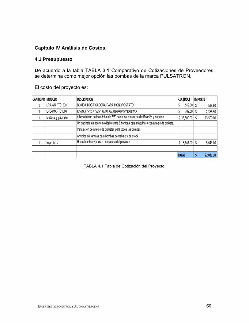
Capítulo IV Análisis de Costos. 4.1 Presupuesto De acuerdo a la tabla TABLA 3.1 Comparativo de Cotizaciones de Proveedores, se determina como mejor opción las bombas de la marca PULSATRON. El costo del proyecto es:
TABLA 4.1 Tabla de Cotización del Proyecto.
CANTIDAD MODELO DESCRIPCION P.U. (DOL) IMPORTE1 LPA3MAPTC1500 BOMBA DOSIFICADORA PARA MONOFOSFATO 519.60$ 519.60$ 3 LPG4MAPTC1500 BOMBA DOSIFICADORA PARA ADHESIVO Y RELEASE 789.50$ 2,368.50$ 1 Material y gabinete tuberia tubing de inoxidable de 3/8" hacia los puntos de dosificación y succión. 13,500.00$ 13,500.00$
Un gabinete en acero inoxidable para 6 bombas para maquina 3 con arreglo de probeta.Instalación de arreglo de probetas para todos las bombas.
Arreglos de valvulas para bombas de trabajo y de stock1 Ingeniería Horas hombre y puesta en marcha del proyecto 5,643.00$ 5,643.00$
TOTAL 22,031.10$

INGENIERÍA EN CONTROL Y AUTOMATIZACIÓN 61
4.2 Análisis de costo- beneficio Se propone reducir las pérdidas en un 50%, es decir el ahorro de pérdidas por cada mes será con un impacto del 50% del total perdido en el histórico de Junio a septiembre del año 2008. El promedio mensual de ahorro es de $70 027.00. 4.3 Beneficios obtenidos
Los beneficios de la aplicación de este proyecto se verán reflejados en los
siguientes aspectos: Seguridad: Las condiciones de instalación y monitoreo por parte del operador
serán más adecuadas, ya que se ubican los contenedores y bombas dosificadoras con una mejor distribución.
Calidad: La calidad del producto semi-terminado de papel, presenta una
mejor convertibilidad y capacidad de enrollado tanto en el área de máquinas de papel como en el área de conversión.
Producción: Nos permite tener una mejor capacidad de respuesta para
realizar ajustes en el acondicionamiento del secador yankee y no tener pérdidas de tiempo por des acondicionamiento.
Concepto Unidades Junio Julio Agosto SeptiembreTiempo por desacondicionamiento min 35 12.5 30 53.510% de tiempo por cambio de cuchillas min 25.5 21.5 27 3110% de tiempo por reventadas min 24 13.5 18 17Tiempo total min 84.5 47.5 75 101.5Ancho útil m 3.3 3.3 3.3 3.3Velocidad de la máquina m/min 1550 1550 1550 1550Gramaje del papel Kg 0.0155 0.0155 0.0155 0.0155Producción total Kg 6699.37125 3765.91875 5946.1875 8047.17375
Ton 6.69937125 3.76591875 5.9461875 8.04717375
Costo por tonelada MNX 10752.5554 10619.4717 10654.92 10654.92Costo total pérdida MNX 72035.3607 39992.0674 63356.1521 85741.9925
Merma rechazada por calidad15% de jumbos por papel picado Ton 0.325 0.55 0.86Rasgado por cuchilla Ton 0.308 0.5 0.5610% de jumbos con reventadas Ton 1.4 1.12 1.97Total Ton 0 2.033 2.17 3.39
Costo de merma MNX 2500 2500 2500 2500Costo total por merma MNX 0 5082.5 5425 8475
Total MNX 72035.3607 45074.5674 68781.1521 94216.9925Total Acumulado MNX 72035.3607 117109.928 185891.08 280108.073
Propuesta de reducción al 50% del problema

INGENIERÍA EN CONTROL Y AUTOMATIZACIÓN 62
4.4 Rendimiento de la inversión ROI
Total USD 22031.1Tipo de cambio 13.8Total MNX 304,029.18
Ahorro Promedio por mes MNX 70,027.02
Tiempo de recuperación de inversión Meses 4.341598255
Costo total del Proyecto
TABLA 4.2 Rendimiento de inversión

INGENIERÍA EN CONTROL Y AUTOMATIZACIÓN 63

INGENIERÍA EN CONTROL Y AUTOMATIZACIÓN 64
5.1 Conclusiones.
La aplicación de este proyecto se ha iniciado en el mes de noviembre por lo que los resultados del impacto económico se deben ver reflejados en el mes de diciembre.
Se realiza la propuesta de automatización de control de flujos químicos en el cual la fundamentación de costo beneficio económico es de gran importancia, ya que con este tipo de análisis se puede cuantificar de manera directa el impacto en la rentabilidad del negocio. De los objetivos establecidos se tiene que:
• Se modifica el diseño de la regadera Yankee Spray, para tener una mejor distribución y asegurar la operación, así como el cambio de cobertura de doble a triple.
• Se determina la capacidad y el tipo de bombas para la dosificación de
químicos, con el proveedor Nalco para mantener el uso de estos equipos y así las refacciones puedan ser más fácil de obtener.
• Se determina la conexión de bombas y configuración de comunicación al
sistema de control (Total Plant Solition, Sistema de control distribuido, marca Honeywell)., ya que son 4 elementos los que se agregan con señal de 4 a 20 mA y esto no afecta debido a la capacidad que tiene el sistema TPS.
• Se configura la pantalla para monitoreo y control de los flujos de químicos
en interfase hombre máquina (HMI) del TPS. En el grupo 53 del TPS, donde se encuentra el sistema Yankee Spray.
• Para un mejor mantenimiento se coloca el gabinete de acero inoxidable en
que se coloca la instalación eléctrica adecuada. Para el mantenimiento de las bombas se tiene una bomba respaldo o para cubrir cualquier falla de las otras, además de que al existir una falla en el control se pueden operar en modo manual.
• Se establece un plan de mantenimiento del Sistema Yankee Spray, el cual
implica:
o Rutinas de limpieza de los filtros, 1 vez por turno. o Rutina de purga del Tanque de mezcla Yankee Spray, 1 vez por día. o Rutina de limpieza de espreas, cada paro programado.

INGENIERÍA EN CONTROL Y AUTOMATIZACIÓN 65
o Rutina de purga de bombas dosificadoras, 1 vez cada semana. o Mantenimiento a bombas dosificadoras, 1 bomba cada mes, (Hacer
uso de bomba de respaldo, cambio de válvulas e inspección de elementos eléctricos y electrónicos.
Los objetivos se cumplieron en un 90%, ya que la configuración de HMI, fue propiamente realizada por el área de Instrumentación y del departamento de ingeniería de la Planta Ecatepc Tissue, ya que su personal se encuentra altamente capacitado en la configuración de de elementos en el sistema Total Plant Solution (TPS). 5.2 Observaciones.
Se observa que las condiciones de seguridad mejoran al tener una instalación adecuada, el tiempo de respuesta para controlar problemas de enrollado mediante el ajuste del acondicionamiento del secador, es más eficiente.
Aunque la calidad del papel se ve influenciada por la gran variedad de
combinaciones de las variables que intervienen en el proceso de fabricación de papel, el tener automatizado el proceso de acondicionamiento del secador yankee, permite disminuir la influencia o afectación de la modificación de los parámetros de los flujos de químicos.
Fuentes de Consulta Información recopilada de SCA México y Centroamérica S.A de C.V Literatura de Pulpa y Papel de archivos generales del área de capacitación de SCA. México y Centroamérica. Información de proveedores de químicos, Nalco, Buckman etc. Visita de páginas como: www.papelnet.cl www.nalco.com www.pulsatron.com Anexos Manual de operación de Bombas Series MP. Manual de Total Plant Solution de Honeywell

Series MP ELECTRONIC METERING PUMPS
Installation Operation Maintenance Instruction
READ ALL WARNINGS CAREFULLY BEFORE INSTALLING

SAFETY INSTRUCTIONS
When using chemical feed pumps, basic safety precautions should always be followed to reduce risk of fire, electric shock, and personal injury. Failure to follow these instructions could result in death or serious injury.
READ ALL INSTRUCTIONS
*** : Secure chemicals and metering pumps, making them inaccessible to children and pets.
*** DO NOT PUMP FLAMMABLE LIQUIDS.
*** Do not cut the plug or ground lug off the electrical cord. Consult a licensed electrician for proper installation or replacement.
** : Always wear protective clothing, including gloves and safety glasses, when working on or near chemical metering pumps.
** Inspect tubing regularly for cracking or deterioration and replace as necessary. (Always wear protective clothing and safety glasses when inspecting tubing.)
** Use CAUTION to keep fingers away from rotating parts.
** If pump is exposed to direct sunlight, use a U.V. resistant tubing.
** Follow directions and warnings provided from the chemical manufacturer. The user is responsible for determining the chemical compatibility with the chemical feed pump.
** Make sure the voltage on the pump name tag matches the installation voltage. If pump fails to start, check line voltage.
** Consult with local health officials and/or qualified water conditioning specialists when treating potable water.
** Always depressurize system prior to installation or disconnecting the metering pump tubing.
** If injection point is lower than the chemical tank and pump, install an anti-siphon valve.
** DO NOT MODIFY PUMP. This poses a potentially dangerous situation and will void the warranty.
* : All pumps are factory tested with water. Remove tubing and thoroughly dry if the chemical being pumped will react with water (for example sulfuric acid).
* Hand tighten plastic connections (Do not use wrench).
* Consult licensed plumber and electrician before installation to conform to local codes.
* NOTE: For accurate volume output, pump must be calibrated under all operating conditions.
2

3
TABLE OF CONTENTS
Page
SAFETY INSTRUCTIONS ............................................................................................................................... 2
INTRODUCTION.............................................................................................................................................. 4
UNPACKING THE PUMP ................................................................................................................................ 5
PRECAUTIONS FOR OPERATION ................................................................................................................ 6
INSTALLATION, PIPING AND WIRING ......................................................................................................... 8
DESCRIPTION OF CONTROLS AND OPERATION..................................................................................... 12
CONTROL OPTIONS .................................................................................................................................... 13
RELAY SETTINGS ........................................................................................................................................ 14
ALARMS......................................................................................................................................................... 15
CONTROL REFERENCE SUMMARY........................................................................................................... 16
START-UP AND OPERATION ...................................................................................................................... 18
ADDITIONAL SETTINGS............................................................................................................................... 23
MAINTENANCE ............................................................................................................................................. 24
TROUBLESHOOTING................................................................................................................................... 26
EXPLODED VIEW DRAWINGS..................................................................................................................... 27
PUMP SPECIFICATIONS.............................................................................................................................. 29
REPAIR SERVICE ......................................................................................................................................... 30

4
INTRODUCTION
These installation, operation and maintenance instructions cover your electronic metering pump. Refer to the pump nameplate to determine the actual model.
PRINCIPLE OF OPERATION
Diaphragm metering pumps are used to dispense chemicals or fluids. This is achieved by an electromagnetic drive mechanism (solenoid) which is connected to a diaphragm. When the solenoid is pulsed by the control circuit, it displaces the diaphragm which, through the use of check valves, moves the fluid out the discharge under pressure. When the solenoid is de-energized it returns the diaphragm and pulls more fluid into the pump head and the cycle repeats.
The stroke rate of the pumps is controlled via the touchpad and present status is indicated by the LCD display. The stroke length is controlled via the stroke length knob.
MATERIALS OF CONSTRUCTION
The wetted materials (those parts that contact the solution being pumped) available for construction are Glass filled polypropylene, PVC, SAN, Hypalon, Viton, PTFE, 316 Stainless Steel, PVDF, Ceramic and Alloy C. These materials are very resistant to most chemicals. However, there are some chemicals, such as strong acids or organic solvents, which cause deterioration of some elastomer and plastic parts, such as the diaphragm, valve seats, or head. Consult Chemical Resistance Guide or Supplier for information on chemical compatibility.
Various manufacturers of plastics, elastomers and pumping equipment publish guidelines that aid in the selection of wetted materials for pumping commercially available chemicals and chemical compounds. Two factors must always be considered when using an elastomer or plastic part to pump chemicals. They are:
1. The temperature of service: Higher temperatures increase the effect of chemicals on wetted materials. The increase varies with the material and the chemical being used. A material quite stable at room temperature might be affected at higher temperatures.
2. Material choice: Materials with similar properties may differ greatly from one another in performance when exposed to certain chemicals.
MANUFACTURER’S PRODUCT WARRANTY
Pulsafeeder warrants all pumps and controllers of its manufacture to be free of defects in material or workmanship. Liability under this policy extends for 24 months from date of shipment from the factory. The manufacturer’s liability is limited to repair or replacement of any failed equipment or part which is proven defective in material or workmanship upon manufacturer’s examination. This warranty does not include removal or installation costs and in no event shall the manufacturer’s liability exceed the selling price of such equipment or part. The manufacturer disclaims all liability for damage to its products through improper installation, maintenance, use or attempts to operate such products beyond their functional capacity, intentionally or otherwise, or any other unauthorized repair. The manufacturer is not responsible for consequential or other damages, injuries or expense incurred through the use of its products. Above warranty is in lieu of any other warranty, whether expressed or implied. The manufacturer makes no warranty of fitness or merchantability. No agent of ours is authorized to provide any warranty other than the above. The European Union Warranty address is listed below, however, please note that the seller should be contacted first.
Steigar 24 NL 1351 AB Almere Netherlands

EUROPEAN TECHNICAL FILE LOCATION
PO Box 91 Washington NE37 1YH United Kingdom
UNPACKING THE PUMP
Check all equipment for completeness against the order and for any evidence of shipping damage. Shortages or damages should be reported immediately to the carrier and to the seller of the equipment.
The carton should contain:
- Metering Pump - Clear Flexible Suction Tubing* - Stiff White Discharge Tubing* - Foot valve/Strainer Assy.* - Backpressure Injection Valve Assy. - One Instruction Book that you are now reading - Bleed Valve Assembly* (most models)
*These items are included with the standard pump. Items may or may not be included depending on model.
Make sure that all items have been removed from the shipping carton before it is discarded.
5

6
PRECAUTIONS FOR OPERATION
Each Electronic Metering Pump has been tested to meet prescribed specifications and safety standards. Proper care in handling, installation and operation will help in ensuring a trouble free installation.
Please read all these cautionary notes prior to installation and start-up of your metering pump.
1. Important: Pump must be installed and used with supplied back pressure/injection valve. Failure to do so could result in excessive pump output flow.
2. Handle the pump with care. Dropping or heavy impact causes not only external damage to the pump, but also to electrical parts inside.
3. Install the pump in a place where the ambient temperature does not exceed 40°C (104°F). The pump is water resistant and dust proof by construction and can be used outdoors, however do not operate the pump submerged. To avoid high internal pump temperatures, do not operate in direct sunlight.
4. Install the pump in a place convenient for its future maintenance and inspection, then fix it to prevent vibration.
5. Protective caps must be removed prior to installing tubing onto valve assemblies. Use tubing of specified size. Connect the tubing to the suction side securely to prevent the entrance of outside air. Make sure that there is no liquid leakage on the discharge side.
6. Be careful to check that the voltage of the installation matches the voltage indicated on the pump nameplate. Each pump is equipped with a three prong plug. Always be sure the pump is grounded. To disconnect, do not pull wire but grip the plug with fingers and pull out. Do not use the receptacle in common with heavy electrical equipment which generates surge voltage. It can cause the failure of the electronic circuit inside the pump.
7. Tampering with electrical devices can be potentially hazardous. Always place chemicals and pump installation well out of the reach of children.
8. Never repair or move the metering pump while operating. Always disconnect electrical power. For safety, always wear protective clothing (protective gloves and safety glasses) when working on or near chemical metering pumps.
9. An air bleed valve is available for most models with tubing connections. Air purges should be performed when the pump chamber contains no fluid at the time of start-up. As a safety measure, connect the return tubing to the air bleed valve and bypass fluid back to storage tank or a suitable drain.
10. Chemicals used may be dangerous and should be used carefully and according to warnings on the label. Follow the directions given with each type of chemical. Do not assume chemicals are the same because they look alike. Always store chemicals in a safe location away from children and others. We cannot be responsible for the misuse of chemicals being fed by the pump. Always have the material safety data sheet (MSDS) available for any fluid being pumped.
11. All pumps are pretested with water before shipment. Remove head and dry thoroughly if you are pumping a material that will react with water, (i.e. sulfuric acid, polymers). Valve seats, ball checks, gaskets, and diaphragm should also be dried. Before placing pump into service, extreme care should be taken to follow this procedure.
12. Valve cartridges are stamped to indicate fluid flow direction. Always install so that markings read from top to bottom, with the arrow pointing in the direction of flow.
13. When metering hazardous material DO NOT use plastic tubing, strictly use proper rigid pipe. Consult supplier for special adapters or valve assemblies.
14. Pump is NOT to be used to handle or meter flammable liquids or materials.
15. Standard white discharge tubing is not recommended for installations exposed to direct sunlight. Consult supplier for special black tubing.
16. Factory will not be held responsible for improper installation of pump, or plumbing. All cautions are to be read thoroughly prior to hook-up and plumbing. For all installations a professional plumber should be consulted. Always adhere to local plumbing codes and requirements.

7
17. When using pump with pressurized systems, make sure the pressure of the system does not exceed the maximum pressure rating on the pump nameplate. Be sure to de-pressurize system prior to hook up or disconnecting the metering pump.
18. Electronic power modules are equipped with automatic reset thermal overload devices and may reset unexpectedly.
19. The pump is designed to operate using a backpressure/injection valve. If the discharge point is below the liquid level of the source or if the discharge pressure is less than the suction pressure, siphoning may occur. To correct this condition, install an anti-siphon valve or other anti-siphon device. Check local regulations which may apply. (Ref. Figure G1).
20. If the power cord is unplugged or in the event of electrical power interruption while the pump is operating, the pump will remember its last operating state for years and will resume operation as before, whenever power is restored.

INSTALLATION, PIPING AND WIRING
The metering pump should be located in an area that allows convenient connections to both the chemical storage tank and the point of injection. The pump is water resistant and dust proof by construction and can be used outdoors, however do not operate submerged. Avoid continuous temperatures in excess of 40°C (104°F). To do otherwise could result in damage to the pump.
MOUNTING
Typical mounting arrangements are shown in Figures B to E.
Important: Injection point must be higher than the top of the solution supply tank to prohibit gravity feeding, unless a suitable backpressure is always present at the injection point. Installation of an anti-siphon valve will prohibit gravity feeding.
1. For wall or shelf mounting, refer to Figure E. Connect suction tubing to suction valve of chemical pump. Suction valve is the lower valve. Tubing should be long enough so that the foot valve/strainer assembly hangs about 1-2 inches (2.5 - 5 cm) above the bottom of chemical tank. To keep chemical from being contaminated, the tank should have a cover.
2. Flooded suction mounting (installing the pump at the base of the chemical storage tank, Figure C) is the most trouble free type of installation and is recommended for very low output requirements. Since the suction tubing is filled with chemical, priming is accomplished quickly and the chance of losing prime is reduced.
To mount pump, drill 4 holes of .25in. (6.3 mm) diameter in the shelf as shown in the dimension drawing (Figure F). Attach pump securely using four #10 bolts and nuts.
8

3. The pump can be mounted to a wall as shown in Figure D. A wall mount bracket kit is available which includes all necessary hardware to mount the pump to the wall. Mounting the pump other than as shown in Figure D defeats the purpose of the housing drain. Mounting dimensions for the pump are provided in Figure F for reference.
4. The pump can be mounted on top of a solution tank as shown in Figure E. Install chemical pump on the cover. Insert suction tubing through the center hole and cut tubing so foot valve/strainer hangs about 1 or 2 inches (2.5 - 5 cm) above the bottom of the tank. Mount the chemical pump rigidly by drilling four .25in. (6.3 mm) holes and using four #10 screws and nuts.
5. USE AN ANTI-SIPHON VALVE IN THE DISCHARGE LINE whenever the fluid pressure in the discharge line is below atmospheric pressure. This can occur if the injection point is on the suction side of a water pump or against a "negative" head such as when feeding down into a well, SEE FIGURE G1.
9
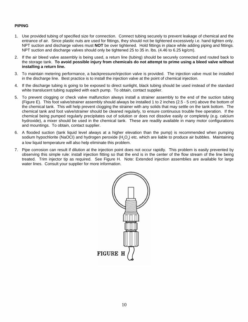
PIPING
1. Use provided tubing of specified size for connection. Connect tubing securely to prevent leakage of chemical and the entrance of air. Since plastic nuts are used for fittings, they should not be tightened excessively i.e. hand tighten only. NPT suction and discharge valves must NOT be over tightened. Hold fittings in place while adding piping and fittings. NPT suction and discharge valves should only be tightened 25 to 35 in. lbs. (4.46 to 6.25 kg/cm).
2. If the air bleed valve assembly is being used, a return line (tubing) should be securely connected and routed back to the storage tank. To avoid possible injury from chemicals do not attempt to prime using a bleed valve without installing a return line.
3. To maintain metering performance, a backpressure/injection valve is provided. The injection valve must be installed in the discharge line. Best practice is to install the injection valve at the point of chemical injection.
4. If the discharge tubing is going to be exposed to direct sunlight, black tubing should be used instead of the standard white translucent tubing supplied with each pump. To obtain, contact supplier.
5. To prevent clogging or check valve malfunction always install a strainer assembly to the end of the suction tubing (Figure E). This foot valve/strainer assembly should always be installed 1 to 2 inches (2.5 - 5 cm) above the bottom of the chemical tank. This will help prevent clogging the strainer with any solids that may settle on the tank bottom. The chemical tank and foot valve/strainer should be cleaned regularly, to ensure continuous trouble free operation. If the chemical being pumped regularly precipitates out of solution or does not dissolve easily or completely (e.g. calcium hydroxide), a mixer should be used in the chemical tank. These are readily available in many motor configurations and mountings. To obtain, contact supplier.
6. A flooded suction (tank liquid level always at a higher elevation than the pump) is recommended when pumping sodium hypochlorite (NaOCI) and hydrogen peroxide (H2O2) etc. which are liable to produce air bubbles. Maintaining a low liquid temperature will also help eliminate this problem.
7. Pipe corrosion can result if dilution at the injection point does not occur rapidly. This problem is easily prevented by observing this simple rule: install injection fitting so that the end is in the center of the flow stream of the line being treated. Trim injector tip as required. See Figure H. Note: Extended injection assemblies are available for large water lines. Consult your supplier for more information.
10

WIRING
1. : Risk of electrical shock. This pump is supplied with a three prong grounding type power plug. To reduce risk of electric shock, connect only to a properly grounded, grounding type receptacle.
2. The metering pump should be wired to an electrical source which conforms to those on the pump nameplate. (Applying higher voltage than the pump is rated for will damage the internal circuit.)
3. In the electronic circuit of the control unit, measures for surge voltage are made by means of surge absorbing elements and high voltage semiconductors. Nevertheless, excessive surge voltage may cause failure in some areas. Therefore, the receptacle should not be used in common with heavy electrical equipment which generates high voltage. If this is unavoidable, however, measures should be taken by (a) the installation of a surge absorbing element (varistor of min. surge resistance 2000A) to the power supply connection of the pump, or (b) the installation of a noise suppression transformer.
4. In the event of electrical power interruption during pump operation, the pump will remember its setting and automatically resume operation as before, whenever power is restored. If a manual reset is required to resume operation, the electrical circuit serving the pump must be suitably wired. Latching power relays which "drop out" upon loss of power, requiring manual reset, are typically used for this purpose.
WELL PUMP SYSTEM INSTALLATION
1. Ensure that the metering pump voltage matches the voltage of the well pump. Typical well pump electrical circuits are shown in Figure J. All electric wiring should be installed in accordance to local electrical codes by a licensed electrician.
2. Install the backpressure/injection (Figure I) on the discharge side of the metering pump into a tee which is installed into the water line going to the pressure tank. Typical installations are found in figures G1, G2 and G3.
Pumps carrying the "ETL Sanitation' approval (tested to NSF standard 50) are listed for swimming pools, spas, and hot tubs, and when proper materials are selected, are capable of handling but not limited to the following chemical solutions:
12% ALUMINUM SULPHATE 5% SODIUM CARBONATE 10% SODIUM HYDROXIDE 2%CALCIUM HYPOCHLORITE 12.5% SODIUM HYPOCHLORITE 10% HYDROCHLORIC ACID
11

DESCRIPTION OF CONTROLS AND OPERATION
INTRODUCTION
The pump performs the following functions:
Selected Controls - Fixed Rate - External Pulse - Straight Pulses - Pulse Storage - Division - Multiplication - External Current Signal - 4-20 mA - 20-4 mA - Stroke Counting - Timed Operation (intervals)
Display Alarms - Circuit Failure - Pulse Overflow - Signal Loss - Pulse Rate High - Full Count
Relay Output (one selected at a time) - Relay Off - Pulse Overflow - Stop Function - Repeat Strokes - Current Signal Loss - Circuit Failure - Full Count
USING THE TOUCHPAD
All adjustments and changes to pump operation (except stroke length) are made through the 6-button touchpad (figure L).
Except for alarm conditions, the LCD display (figure K) always presents either the present operating condition or a prompt which must be answered in order to commence operation.
There are two types of prompts:
Prompts in the form of questions (marked with a flashing question mark) are used to navigate through the menu options. These prompts are answered by pressing either the or buttons.
Prompts marked with alternating up and down arrows are always encountered when a numerical value must be selected (i.e., stroke rates, counts, run times, ratios). These prompts are answered by pressing either the or buttons to change the display value to the desired setting. After the desired value has been set in the display, press
to accept this value and continue or press to return to the main menu.
To stop the pump at any time, press the red button. To resume operation as before, press the button.
To display the present stroking rate as a percentage of the maximum rate of the pump at any time, press the button. Press any button to return to the normal display.
Pressing the button while the pump is in operation will bring up the relay option menu. Pressing will allow scanning the relay output options. When the desired option is presented press the
button, this will set the relay option and the screen will automatically return to the operating display.
12

13
HELPFUL HINTS
You can always get to where you want to go simply by accepting or rejecting choices presented.
If you find yourself within a menu where you don't want to be, keep selecting No until you return to the main menu.
If you go past the desired selection by mistake, keep selecting No and the pump will take you back to it.
If you press an inappropriate button, you will be notified by a message which lasts for several seconds.
A partly flashing display requires your response.
A flashing question mark requires a Yes or No answer.
Flashing arrows require an Up or Down numerical adjustment. To make large numerical adjustments quickly, hold down either the Up or Down arrow buttons. The value in the display will change at an increased rate.
A fully flashing display is an alarm.
If power is interrupted, the pump will automatically resume operating where it left off when power is restored. The pump will remember this for years while power is off.
CONTROL OPTIONS
FIXED RATE
The pump operates continuously at the set rate over the span 1-100% of maximum.
EXTERNAL PULSE CONTROL - STRAIGHT PULSES
Each pulse received from the external signal port causes the pump to immediately stroke once at a rate limited by the maximum rate of the pump, 125 strokes per minute. If any pulses are received at a faster rate, the Pulse Rate High alarm is triggered, during which the pump operates at its maximum rate and does not respond to the excess pulses.
In the Pulse Storage option, any pulse frequency received which is at a higher rate than the pump can respond to (125 contacts per minute), will cause excess pulses to be accumulated in memory. The pump will work off the excess pulses at a rate of 125 strokes per minute when the signal level drops below the maximum rate. If the accumulation exceeds 9,999 pulses, memory storage capacity is exceeded and the Pulse Overflow alarm is triggered. During the Pulse Overflow condition the pump operates at 125 strokes per minute; when the incoming rate drops below 125 pulses per minute, normal Pulse Storage operation resumes, starting with a full memory.
EXTERNAL PULSE CONTROL - DIVISION
The pump operates as described above except that incoming pulses are divided by a value from 1 to 999 prior to actuating the pump. For example, at a setting of 5, every fifth incoming pulse causes the pump to stroke once.
The Pulse Storage option operates as described above.
Pulse division makes it possible to "tune" the pump by adjusting its response to an external pulse signal, such as that from a flow meter, which is of too high a frequency to cause the desired feed by directly stroking the pump.

14
EXTERNAL PULSE CONTROL - MULTIPLICATION
The pump operates as described previously except that incoming pulses are multiplied by a value from 1 to 999 prior to actuating the pump and then worked off at a selected stroking rate. For example, at a multiplier of 5 and a stroking rate of 25%, each incoming pulse causes the pump to stroke five times at 25% stroking rate and then stop. During operation, the display shows the present value and the present count on a running basis. Unless Pulse Storage is in effect, additional external pulses received while responding to a previous pulse are ignored.
This option is similar to Stroke Counting (see below) except that action is initiated automatically by one or more external pulses rather than once manually by the user. There is no Full Count alarm as in Stroke Counting since it is always possible to receive additional external pulses.
The Pulse Storage option operates as described above.
EXTERNAL CURRENT SIGNAL CONTROL
In the 4-20 mA (direct) option, the pump responds linearly to a current signal from the incoming signal port over the full operating span from 0% (4 mA) to 100% (20 mA). For example, a 12 mA signal causes the pump to operate at 50% of full.
In the 20-4 mA (reverse) option, pump response is the reverse of the above: from 0% (20 mA) to 100% (4 mA).
In both the 4-20 mA and 20-4 mA options, a Ratio from 1 to 99% can be applied to step down the response. For example, a 12 mA signal at a 50% ratio causes the pump to respond as if the signal were only 6 mA (50% of 12 mA).
In all the above options, the Signal Loss alarm is triggered whenever the signal drops below approximately 2 mA for several seconds. The pump stops operating during the loss of signal condition, and automatically resumes normal operation when the signal is restored.
STROKE COUNTING
The pump delivers a preset number of up to 9,999 strokes at a selected stroking rate. During operation, the display shows the preset value and the present count on a running basis. When the preset number of strokes has been delivered, the pump stops and the Full Count alarm is triggered. Pressing Yes when the Full Count alarm is displayed brings up the reset prompt. Continue pressing Yes to repeat the same stroking cycle or change the displayed values as they are presented to change the stroke count.
This option is similar to External Pulse Control - Multiplication (see above) except that action is initiated once manually by the user rather than by one or more external pulses.
TIMED OPERATION*
The pump operates for selected run times from 1 to 999 minutes (16.65 hours) at selected intervals from 1 to 999 hours (41.625 days) at a selected stroking rate. For example, the pump might be set to operate for 60 minutes every 168 hours (7 days), at a 50% stroking rate. During operation the pump displays the run time in minutes and the interval in hours.
* Pumps with version numbers "B4" and "GB4" (displayed on power-up) use settings of seconds and minutes.
RELAY SETTINGS
The following relay output options can be brought up on the menu by pressing the Yes button while the pump is in an operating condition (Relay options vary with operating condition). Press the No button to scan through the options available. Only one relay output option may be selected. When the desired option is displayed, press the Yes button. This will set the relay for the chosen option and the display will automatically return to the previous operating display.

15
RELAY OFF
In all control options the relay remains open at all times.
STOP FUNCTION
In all control options the relay is normally open and closes while the Stop Function is activated through the stop port.
CURRENT SIGNAL LOSS
In any Current Signal control option, the relay is normally open and closes while the Signal Loss alarm is in effect.
FULL COUNT
In the Stroke Counting control option, the relay is normally open and closes while the Full Count alarm is in effect.
PULSE OVERFLOW
In any External Pulse control option with Pulse Storage, the relay is normally open and closes while the Pulse Overflow alarm is in effect.
REPEAT STROKES
In all control options, the relay is normally open and closes momentarily during each stroke of the pump. If the pump is equipped with a 24 VDC signal relay output, this function may be used to pace another externally paced pump.
CIRCUIT FAILURE
At all times, the relay is normally open and closes while the Circuit Failure alarm is in effect. The numbers which flash alternately with the alarm signal are for failure diagnosis at the factory.
ALARMS Alarms are distinguished by a fully flashing display.
CIRCUIT FAILURE
At all times, pumping is disabled and the pump will no longer operate until repaired.
SIGNAL LOSS
In any Current Signal option, the Signal Loss alarm is triggered whenever the signal drops below approximately 2 mA for several seconds. The pump stops operating during the loss of signal condition and resumes normal operation when the signal is restored. This includes the 20-4 mA option, in which a low current (4 mA) signal normally calls for full pump output in order to prevent overfeeding in the event of signal loss.
FULL COUNT
In the Stroke Counting control option, when the preset number of strokes has been delivered and the pump stops, the Full Count alarm is triggered.
PULSE OVERFLOW
In the Pulse Storage option, when memory capacity is exceeded the Pulse Overflow alarm is triggered. The pump continues to respond to external signal pulses as if 9,999 pulses were in storage.
PULSE RATE HIGH
In any External Pulse Control option without Pulse Storage, receipt of any pulses at a faster rate than maximum pump stroking rate, 125 strokes per minute, the Pulse Rate High alarm is triggered. The pump continues to operate at its maximum rate and does not respond to the excess pulses.
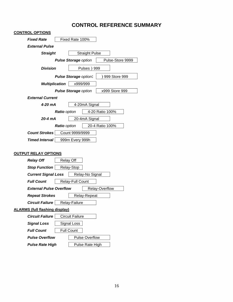
16
CONTROL REFERENCE SUMMARY CONTROL OPTIONS
Fixed Rate Fixed Rate 100%
External Pulse
Straight Straight Pulse
Pulse Storage option Pulse-Store 9999
Division Pulses ) 999
Pulse Storage option: ) 999 Store 999
Multiplication x999/999
Pulse Storage option x999 Store 999
External Current
4-20 mA 4-20mA Signal
Ratio option 4-20 Ratio 100%
20-4 mA 20-4mA Signal
Ratio option 20-4 Ratio 100%
Count Strokes Count 9999/9999
Timed Interval 999m Every 999h
OUTPUT RELAY OPTIONS
Relay Off Relay Off
Stop Function Relay-Stop
Current Signal Loss Relay-No Signal
Full Count Relay-Full Count
External Pulse Overflow Relay-Overflow
Repeat Strokes Relay-Repeat
Circuit Failure Relay-Failure
ALARMS (full flashing display)
Circuit Failure Circuit Failure
Signal Loss Signal Loss
Full Count Full Count
Pulse Overflow Pulse Overflow
Pulse Rate High Pulse Rate High

17
SETTINGS OPTIONS
Settings?
Flow Verify? Yes=On No=Off
Relay Output?
Relay-Stop?
Relay-Repeat?
Rel-No Signal?
Rel-Full Count?
Relay-Overflow?
Relay-Failure?
Rel-Flow Vrfy?
Relay-Off?
Factory Init?
Init Settings?
Are You Sure?
Volume-Units?
Units = GPD?
Reset Totals?
Are You Sure?
Calibrate Flow?
Stroke = 100
Run Calib?
Language?
English?
French?
German?
Spanish?

START UP AND OPERATION
POWER
All metering pumps are available in 115 volts at 50/60 Hertz, single phase. Optionally 230 volts at 50/60 Hertz, single phase can be provided. Prior to start-up always check to insure that the pump voltage/frequency/phase matches that of the power supply.
: If pump is fitted with a PVC pump head (7th position of model number is “V”. Note: PVC is gray, not black), uniformly hand tighten the four head screws before use (18-22 inch pounds / 3.21-3.93 kg/cm). Periodically tighten after installation.
PRIMING
: When working on or around a chemical metering pump installation, protective clothing and gloves and safety glasses should be worn at all times.
All pumps are tested with water. If the chemical to be pumped reacts when mixed with water (e.g. sulfuric acid, polymer) the pump head should be removed and dried thoroughly along with the diaphragm and valve seats.
1. Turn on the power to the pump. Operate the pump in the fixed rate control mode at 100% (full) rate. The green LED will light up and flash off each time the pump strokes.
2. Adjust the stroke length knob to the 100% setting mark (for more information see “Stroke Length Adjustment” on the following page).
3. If the discharge line is connected directly to a pressurized system it should be temporarily bypassed during priming of the pump. A bleed valve will simplify this operation by allowing easy bypass of the discharge fluid. All air must be purged from the pump head before the pump will pump against pressure.
Air Bleed Operation:
A) While pump is running, turn adjustment screw counterclockwise.
B) Run with valve open until a solid stream of fluid comes out of the bypass tubing (1/4 x 3/8 supplied with valve), no air bubbles.
C) Close air bleed valve by turning adjustment screw clockwise.
4. Chemical should reach the pump head after a few minutes of operation. If not, remove the discharge fitting and moisten the discharge valve area (ball check and valve seats) with a few drops of chemical being fed to the metering pump. For safety, always use protective clothing and gloves, wear safety glasses and use a proper container to hold the chemical.
5. If the pump continues to refuse to prime, refer to Troubleshooting Section of these instructions.
6. Turn the power on once more and adjust the pump flow to the desired rate (see “Controlling Procedure” below).
7. Always check the calibration of the pump after start-up. It’s best to calibrate the pump under your typical use conditions.
18

STROKE LENGTH ADJUSTMENT
Stroke length can be controlled within 0 to 100% of the diaphragm displacement. (It should be controlled within 20 to 100% for practical use.)
Stroke length can be set by means of the stroke length adjusting knob while the pump is in operation. Do not turn the knob while the pump is stopped.
Controlling Procedure (for fixed rate):
Proper set points for stroke length should be determined after consideration of the pump and characteristics of the fluid. The following procedure is recommended from the viewpoint of pump performance. Note: The closer the stroke length is to 100%, the better the pump performance will be.
A) Set the stroke length to 100%. Measure the output capacity. B) Adjust the stroke rate frequency to obtain the desired output. If adjustment by stroke rate alone does not
bring the output low enough, the stroke length may be adjusted to lower the maximum output. C) Measure the output capacity to ensure that the required value is obtained.
Example Selected Model = LMD4 Set Stroke Length = 100% Set Stroke Rate = 100% Output Capacity = 21 GPD* (Rated Pressure)
Desired Flow = 17 GPD Adjust Stroke Rate to 81% Output Capacity = 17 x 100 = 81% (approx.)* 21
Thus to obtain the desired flow, stroke length is set at 100% and stroke rate is set at 81% i.e. output capacity = 0.81 x 21 = 17 GPD*
* Check these values by measurement. Output capacity is higher when feeding against less than rated pressure.
19

OPERATION BY EXTERNAL INPUT SIGNALS:
The pump can be controlled by three types of input signals. All are fully isolated from AC input power and from Earth ground. The input socket connections are located at the bottom of the control panel face and the signal cords are provided with the pump. Remove rubber plugs to access plug sockets.
Stop Function:
Operation of the pump can be stopped by an external signal input. When the external signal is input to the stop terminals, the red light goes on and operation of the pump is stopped. The stop function overrides all control options and input signals at other terminals. Previous operation resumes when the stop signal is removed.
: Operation of more than one pump from the same contact closure will damage the pump circuits. When such operation is required, the pump circuits must be electrically isolated from one another by means of a multi-contact control relay or similar means.
Input signals should be no-voltage signals from relay contacts, etc. and the input of other signals is prohibited. (In case of relay contacts, electric resistance must be 100 ohms or below when ON and 1 Mega ohm or above when OFF).
The stop function is commonly used in conjunction with a tank float switch. The float switch contacts are normally open but when the tank level falls past a certain point the contacts close and the pump stops. Signal cord is provided with the pump.
External Pacing Function:
Pump stroking can be controlled by an external pulse signal through the external signal terminals while the pump is in one of the external pacing control modes.
: Operation of more than one pump from the same contact closure will damage the pump circuits. When such operation is required, the pump circuits must be electrically isolated from one another by means of a multi-contact control relay or similar means.
After receiving an input signal, the pump generates the necessary power pulse to actuate the solenoid. The external signal input is debounced by the pump circuit.
Input signals should be no-voltage signals from relay contacts, etc. and the input of other signals is prohibited. (In the case of relay contacts, electric resistance must be 100 ohms or below when ON and 1 Mega ohm or above when OFF). The pulse duration of the input signal must be 10 milliseconds or over and the frequency of input signal must not exceed 125 times/min unless accommodated by pulse division or pulse storage. Signal cord is provided with the pump.
4-20 mA / 20-4 mA Function:
The pump stroking rate can be controlled by a 4-20 mA direct or an inverse current signal when in one of the current signal modes.
The pump automatically adjusts stroking rate according to the signal level provided to the pump.
Pumps may be wired in series to the current signal providing that the signal source is sufficient to handle the load (each pump has an impedance of 187 ohms).
The pump responds to a straight (non-ratio) 4-20 mA signal as follows: (Figure N below shows straight response and response ratioed by 25, 50 and 75%):
The pump responds to a 20-4 mA signal as follows. (Figure O below shows straight response and response ratioed by 25, 50 and 75%):
20

The signal cord is provided with the pump and has the following polarity: White = Positive (+) Black = Common Signal input impedance is 100 ohms.
OUTPUT RELAY
Each pump has the option of being provided with one of two separate normally open output relay options as described below. Relays close according to the option selected, and remain closed during the condition specified for the selected option except for the Repeat Strokes option.
21

The Signal Level output relay option is via the output signal terminals on the pump control panel. It is designed to provide direct or inverted voltage output signals as shown in figure O. The voltage input must have a high-impedance characteristic and must not exceed 24 VDC. The pump circuit can source or sink a maximum current of 10 mA. The signal cord is provided with the pump and has the following polarity when connected to the pump terminals.
White = Positive (+) Black = Common
The Power Level option is via the power relay cord which exits the pump below the control panel. The power level relay is a zero-crossing triac-type solid-state switch as seen in figure Q which is designed to switch AC current only and has the following ratings: Voltage Current Power Minimum = 12 VAC, 50/60 HZ minimum = 10 mAmps minimum = .12 watts (at 12 VAC) Maximum = 250 VAC, 50/60 HZ maximum = .5 Amps maximum = 120 watts (at 240 VAC)
* Load can be any device which meets the above voltage and current limits (i.e., lamp, alarm, siren, relay, etc.)
: Do not apply power directly to the relay cord without a sufficient load to limit current as indicated above. Do not exceed the specified voltage rating. Excess current or voltage will damage the pump and cause fire and electrical shock hazards. Do not install any type of standard power plug to the relay cord.
22
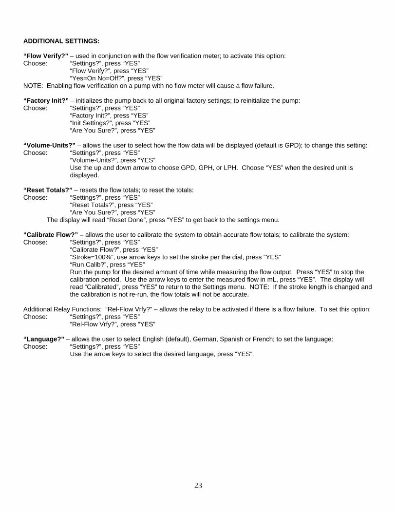
23
ADDITIONAL SETTINGS: “Flow Verify?” – used in conjunction with the flow verification meter; to activate this option: Choose: “Settings?”, press “YES” “Flow Verify?”, press “YES” “Yes=On No=Off?”, press “YES” NOTE: Enabling flow verification on a pump with no flow meter will cause a flow failure. “Factory Init?” – initializes the pump back to all original factory settings; to reinitialize the pump: Choose: “Settings?”, press “YES” “Factory Init?”, press “YES” “Init Settings?”, press “YES” “Are You Sure?”, press “YES” “Volume-Units?” – allows the user to select how the flow data will be displayed (default is GPD); to change this setting: Choose: “Settings?”, press “YES” “Volume-Units?”, press “YES” Use the up and down arrow to choose GPD, GPH, or LPH. Choose “YES” when the desired unit is
displayed. “Reset Totals?” – resets the flow totals; to reset the totals: Choose: “Settings?”, press “YES” “Reset Totals?”, press “YES” “Are You Sure?”, press “YES” The display will read “Reset Done”, press “YES” to get back to the settings menu. “Calibrate Flow?” – allows the user to calibrate the system to obtain accurate flow totals; to calibrate the system: Choose: “Settings?”, press “YES” “Calibrate Flow?”, press “YES” “Stroke=100%”, use arrow keys to set the stroke per the dial, press “YES” “Run Calib?”, press “YES”
Run the pump for the desired amount of time while measuring the flow output. Press “YES” to stop the calibration period. Use the arrow keys to enter the measured flow in mL, press “YES”. The display will read “Calibrated”, press “YES” to return to the Settings menu. NOTE: If the stroke length is changed and the calibration is not re-run, the flow totals will not be accurate.
Additional Relay Functions: “Rel-Flow Vrfy?” – allows the relay to be activated if there is a flow failure. To set this option: Choose: “Settings?”, press “YES” “Rel-Flow Vrfy?”, press “YES” “Language?” – allows the user to select English (default), German, Spanish or French; to set the language: Choose: “Settings?”, press “YES” Use the arrow keys to select the desired language, press “YES”.

MAINTENANCE
: Before performing any maintenance or repairs on chemical metering pumps, be sure to disconnect all electrical connections and insure that all pressure valves are shut off and pressure in the pump and lines has been bled off.
Always wear protective clothing, gloves and safety glasses when performing any maintenance or repairs on chemical metering pumps.
ROUTINE MAINTENANCE
1. Routinely check the physical operating condition of the pump. Look for the presence of any abnormal noise, excessive vibration, low flow and pressure output or high temperatures [when running constantly at maximum stroke rate, the pump housing temperature can be up to 160°F (70°C)]
2. For optimum performance, cartridge valves should be changed every 4-6 months. Depending on the application, more frequent changes may be required. Actual operating experience is the best guide in this situation. Repeated short-term deterioration of valve seats and balls usually indicates a need to review the suitability of wetted materials selected for the application. Contact the supplier for guidance.
3. Check for leaks around fittings or as a result of deteriorating tubing e.g. when standard white translucent discharge tubing is exposed to direct sunlight. Take appropriate action to correct leak by tightening fittings or replacing components.
4. Keep the pump free of dirt/debris as this provides insulation and can lead to excessive pump temperatures.
5. If the pump has been out of service for a month or longer, clean the pump head/valve assemblies by pumping fresh water for approximately 30 minutes. If the pump does not operate normally after this “purging run”, replace cartridge valve assemblies.
DISASSEMBLY AND ASSEMBLY
DIAPHRAGM REMOVAL
1. Flush pump head and valve assemblies out by running pump on water or other suitable neutralizing solution. Wash outside of pump down if chemical has dripped on pump.
2. Set stroke length of pump to 0% and unplug pump.
3. Disconnect tubing or piping from the pump. Remove the four pump head screws and then remove the pump head assembly.
4. Remove the diaphragm by grasping it at the outer edges and turning it counterclockwise until it unscrews from the electronic power module (EPM). Don’t lose the deflection plate or diaphragm shims which are behind the diaphragm. Note shim quantity can be from 0 to 2.
5. Inspect diaphragm if it is intended to be used again. Look for indications of the TFE face being overstretched, (localized white areas) or the elastomer on the back of the diaphragm being worn. Excessive amounts of either condition require diaphragm replacement.
24

DIAPHRAGM REPLACEMENT
Refer to drawings in the back of the manual.
1. When replacing the diaphragm, it’s always a good idea to replace the valve cartridges and other worn parts. A kit is available from your supplier with all parts necessary to completely rebuild your pump’s wet end. All your supplier needs to know is the “KOPkit No.” on your pump’s nameplate to supply this kit.
2. Set pump stroke length to 0% and unplug the pump.
3. If you kept the shims from the original diaphragm or know the original quantity you can avoid Step #4 for shimming the diaphragm and go to Step #5.
4. Slide the diaphragm deflection plate onto the back of the diaphragm stud, radius side towards the diaphragm. Next slide two shims onto the diaphragm threaded stud and screw the diaphragm into the EPM unit. Refer to Figure R. Turn diaphragm clockwise until deflection plate and shims are tight against solenoid shaft, diaphragm stops turning. If there is a gap between the adaptor and diaphragm, repeat the procedure removing one shim each time until the diaphragm just touches the adaptor or is slightly recessed.
5. Apply grease to areas of the diaphragm that contact the deflection plate or radius on the adaptor.
6. Screw the diaphragm into the EPM unit’s shaft with the deflection plate and appropriate number of shims in between.
7. Adjust stroke length to 50%. It is easier to do this if you temporarily turn the pump on. Place the pump head onto the adaptor with valve flow arrows pointing up and install and tighten pump head screws. Tighten screws until pump head pulls up against adaptor.
8. Adjust stroke length back to 100% for easier priming and place pump back into service.
VALVE REPLACEMENT
1. Flush pump to clean any chemical from pump head.
2. Unplug pump, release system pressure, and disconnect any tubing or piping.
3. Unscrew valve cartridges and discard. Also remove O-Rings down inside pump head.
4. Using new O-Rings, install new valve cartridges with stamped letters reading from top to bottom, and the arrow pointing in the direction of flow. Hand tighten only, do not use wrenches or pliers. This is especially important when the pump head is SAN material.
5. Reconnect tubing or piping and reinstall the pump.
6. Check for leaks around newly installed fittings.
25

26
TROUBLESHOOTING PROBLEM PROBABLE CAUSE REMEDY
LOSS OF CHEMICAL RESIDUAL
1. Pump setting too low. 2. Scale at injection point 3. Solution container allowed to run dry
1. Adjust to higher setting (pump must be operating during stroke length adjustment). 2. Clean injection parts with 8% muriatic acid or undiluted 3. Refill the tank with solution and prime. See start-up and operation section
TOO MUCH CHEMCIAL
1. Pump setting too high1. 2. Chemical in solution tank is too rich 3. Siphoning of chemical into well or main line.
1. Lower pump setting (pump must be operating to adjust stroke length knob). 2. Dilute chemical solution. NOTE: For chemical that reacts with water, it may be necessary to purchase a more dilute grade of chemical direct from chemical supplier. 3. Test for suction or vacuum at the injection point. If suction exists, install an anti-siphon valve.
LEAKAGE AT TUBING
CONNECTIONS
1. Worn tube ends 2. Chemical attack
1. Cut off end of tubing (about 1”) and then replace as before 2. Consult your seller for alternate material.
FAILURE TO PUMP
1. Leak in suction side of pump 2. Valve seats not sealing 3. Low setting on pump 4. Low solution level 5. Diaphragm ruptured 6. Pump head cracked or broken 7. Pump head contains air or chlorine gas 8. Breakdown or disconnection of wiring 9. Voltage drop 10. Malfunction of electronic control board
1. Examine suction tubing. If worn at the end, cut approximately an inch off and replace 2. Clean valve seats if dirty or replace with alternate material if deterioration is noted 3. When pumping against pressure, the dial should be set above 20% capacity for a reliable feed rate 4. Solution must be above foot valve 5. Replace diaphragm as shown in the “Maintenance Section”. Check for pressure above rated maximum at the injection point. NOTE: Chemical incompatibility with diaphragm material can cause diaphragm rupture and leakage around the pump head. 6. Replace pump head as shown in “Maintenance Section”. Make sure fittings are hand tight only. Using pliers and wrench can crack pump head. Also, chemical incompatibility can cause cracking and subsequent leakage. 7. Bleed pump head, see “Air Bleed Operation”. 8. Connect wiring properly. Check fuse or circuit breaker 9. Take measures after investigation of cause 10. Contact supplier
PUMP LOSES PRIME
1. Dirty check valve 2. Ball checks not seating or not sealing properly 3. Solution container allowed to run dry 4. Chemical outgassing
1. Remove and replace or clean off any scale or sediment 2. Check seat and ball checks for chips, clean gently. If deformity or deterioration is noted, replace part with proper material. Resulting crystals can hold check valves open, therefore the valves must be disassembled and cleaned. Be sure to replace all parts as shown in the Parts Diagram at the end of the manual. 3. Refill the tank with solution and prime. See Start-Up and Operation section 4. Bleed gas, use flooded suction, maintain chemical at room temperature (approx. 20° F / -6° C).
LEAKAGE AT FITTING
1. Loose fittings 2. Broken or twisted gasket 3. Chemical attack
1. Tighten hand tight. Replace gasket if hand tight does not stop leakage 2. Check gaskets and replace if broken or damaged 3. Consult your pump supplier for alternate material
PUMP WILL NOT PRIME
1. Too much pressure at discharge 2. Check valves not sealing 3. Output dials not set at maximum 4. Suction lift height too much 5. Pump equipped with spring loaded high viscosity valves
1. Turn off all pressure valves, loosen outlet tubing connection at discharge point. Remove discharge valve cartridge. Dampen ball check and valve seats with a few drops of solution. Set pump dial to maximum rate. When pump is primed, reconnect all tubing connections. 2. Disassemble, loosen, clean and check for deterioration swelling. Reassemble and wet the valve assembly, then prime. See Start-Up Operation section. 3. Always prime pump with out dial set a maximum rated capacity 4. Decrease suction lift or pull vacuum on pump discharge until pump is primed 5. Loosen discharge valve to aid in priming, take necessary safety precautions or apply vacuum to pump discharge

27

28

Specifications Pressure, MAX, PSI/BAR@ GPD/GPH/LPD
300/203/.13/11
Capacity, MAX, GPD/GPH/LPD@ PSI/BAR
500/20.8/189020/1.4
Reproducibility, % MAX Capacity 2
Viscosity, MAX, CPS (1) 1000
Suction Lift @ 1 CPS, MAX, FT/M@ 3000 CPS
10/3.1 (once primed)3.5/1.1
Controls 6-Station Membrane Switch
Status Display16-Position LCD Dot MatrixBacklight
LED Indicator Lights,Panel Mount
Power On - GreenPulsing - Green FlashingStop - Red
Stroke Frequency, MAX, SPM 125
External Stroke Frequency Control,(Automatic)
4-20 mADC, 20-4 mADCExternal Pacing
Stroke Frequency Turn Down Ratio 100:1
Stroke Length Turn Down Ratio 10:1
Output Relay (Signal Level Option) 24 VDC, 10 mA
Output Relay (Power Option) 250 VAC, 50/60 HZ, .5A
Power Input115 VAC/50-60HZ/1ph230 VAC/50-60HZ/1ph
Current Draw @ 115 VAC, AMPS 1
Average Input Power @MAX SPM, Watts 130
Circuit Board Protection Circuit Breaker (Panel Mount)
Temperature, MAX, F/ C- Environmental (Shaded) 104/40
Connections - Tubing (Suction & Discharge)... - Piping (Suction & Discharge)
.25" ID X .38" OD
.38" ID X .50" OD
.50" ID X .75" OD
.25" FNPT
.50" FNPT
29
30
REPAIR SERVICE
Normally following the instructions in the previous sections of the manual will rectify any pump problems. If, however, after following these instructions the pump does not perform properly, it can be returned for repair. Please follow the instructions below:
1. Pump cannot be serviced properly if the original pump nameplate or data contained on the nameplate is not intact.
2. Thoroughly flush pump head and outside of pump with water or a suitable fluid to neutralize any residual chemical left in pump.
3. Include written explanation of the following:
A) Problem
B) Pumped Fluid
Name
Viscosity
Fluid Temperature
C) Pressure @ Discharge
@ Suction
or Suction Lift
D) Environmental Temperature
E) Electrical Service
Volts
Hz
Phase
F) Nameplate Data
Series
Serial #
KOPkit #
4. Package the pump in the original box if available and send to the address specified by your pump supplier.

Keep-On-Pumping kits that can save you time and money!
31
The manufacturer has built a reputation for superior reliability by supplying carefully-designed, high-quality equipment. Even the best equipment, however, requires a minimal amount of maintenance. KOPkits are designed to guard against unnecessary downtime and assure you the highest level of efficient and uninterrupted service.
KOPkits contain those recommended spare parts which will most likely require normal maintenance.
A typical KOPkit includes Valve Cartridges with O-Rings, Head, Diaphragm, Secondary O-ring Seal, Head Screws, Washers and an exploded view drawing.
KOPkits will save you money. When you need a part, you’ve got it! You can cut downtime and production loss from days to minutes. You also save by buying parts in KOPkit form compared with buying individual parts.
Each KOPkit part is vacuum-sealed to keep it clean even when stored for long periods of time.
A KOPkit is a troubleshooter’s best friend. In the event of a breakdown, it will put you back in business fast! Preventive maintenance will insure continuous high performance of your pump.
Keep on pumping! Get all the money-saving and security benefits of KOPkits immediately.
Selecting a KOPkit
The KOPkit part number is displayed on the pump model label as shown. To order the proper KOPkit model, begin with the letter "K" followed by the 4th, 7th, 8th, 9th and the 10th digit of the pump model number.
L9404500-000 PRINTED IN U.S.A. Revision A

ProM
inen
t®
beta–1
ProMinent® beta Metering Pumps
The Drive UnitPump housingConstructed of fiberglass-rein-forced PPE plastic, with a NEMA4x enclosure rating to protectagainst corrosion, dust and water.
Solenoid driveThe drive unit houses a short-stroke solenoid with a maximumstroke length of 0.05" (1.25 mm).It is equipped with a noise sup-pressing mechanism for quietoperation and has only one movingpart, the armature.
Operating on pulse action, eachpulse generates a magnetic field inthe solenoid coil. This magneticfield moves the armature forward.At the end of the armature is thediaphragm. The diaphragm pushesinto the dosing head cavity forcingchemical out of the discharge
The beta pump series is a solenoid-driven, diaphragm-type metering pump featuring the following:• Microprocessor based
• Capacity range 0.19 - 8.4 gph (0.74 - 32 L/h)
• Continuous stroke length adjustment from 0 to 100%
• 10-setting stroke frequency adjustment from 10 to 100%
• Maximum stroke rate: 180 spm
• Repeatability +/- 2% when used according to operatinginstructions
• Liquid end materials: PP, PVC, Acrylic, PTFE, SS
• Auto degassing liquid ends
• High viscosity liquid ends
• External access to options
• 12-24 VDC low voltage option
ProMinent® solenoid-driven meteringpumps consist of two main compo-nents: the pump drive unit and theliquid end. The beta series offers twodrive (solenoid) sizes: beta/4 (BT4a)and beta/5 (BT5a). Operatingprinciples and options are identical,and both units offer maximumbackpressures up to 253 psig (17.5bar). Capacity range for the beta/4 is0.19 to 5 gph (0.74 to 19 L/h); beta/5is 1.1 to 8.4 gph (4.1 to 32 L/h).
Feed rate is determined by strokelength and stroking rate: stroke lengthcan be varied from 0 to 100% with anadjustment ratio of 10:1. It is setmanually by the adjustment knobon the front of the pump.
Stroke rate can be adjusted in 10%increments between 10 and 100% viathe multifunction switch. This switch isalso used to select voltage-free On/Offexternal pulse contact, pump stop, ortest (for priming).
CUTAWAY VIEW OF PROMINENT BETA SOLENOID-DRIVEN METERING PUMP
1 HOUSING
2 LIQUID END
3 DIAPHRAGM
4 BACKPLATE
5 SOLENOID
6 SOLENOID COIL
7 SOLENOID AXLE
8 ARMATURE
9 COVER
10 STROKE ADJUSTMENT
SCREW
11 STROKE ADJUSTMENT
AXLE
12 STROKE ADJUSTMENT
KNOB
valve. When the magnetic field isde-energized, a spring returns thearmature and diaphragm to theiroriginal position. This returnmovement draws chemical into thedosing head cavity through thesuction valve.
In the event of a diaphragm rupture,the liquid end has a weep hole onthe bottom of the backplate todirect chemical out of the pump andaway from the solenoid. Anoptional diaphragm failure monitorcan be used to stop the pump andindicate a problem.
The stroke-length adjusting mecha-nism is directly connected to thesolenoid. Adjustment results in anaccurate self-locking stroke lengthsetting.
The Diaphragm
The diaphragm is constructed offabric-reinforced EPDM elastomerwith a plastic core and a PTFE-facing. It is chemically resistantagainst virtually all process fluidsand can be used over a widetemperature range.
The beta pump is designed with thenew-style convex diaphragm. Thecurved shape contributes to moreprecise metering and alleviatesstress placed on the diaphragm byreducing liquid end dead volume.

ProM
inen
t®
beta–2
Power SupplyThe beta metering pumps accept100-115, 200-230 or a universal 100-230 volt power supply +/- 10%,single phase, 50/60 Hz, with a 1.15service factor. Performance isidentical whether operated on 50 Hzor 60 Hz power. The power cord isdetachable.
AN EXTERNAL PANEL IN THE BASE OF THE
PUMP ENABLES OPTIONAL RELAYS TO BE
INSTALLED ON-SITE.
The Liquid End
The beta metering pump liquid endsare available in five material versions:
• Polypropylene (PP)• PVC (PC)• Acrylic/PVC (NP)• PTFE (TT)• 316 Stainless steel (SS)
Some liquid ends are interchangeablebetween the BT4a and BT5a (see tableon page 4).
Options include a manual bleed valvefor easy priming and continuousbleeding of fluids that tend to off-gas(available with versions 1000-0713PP, NP and PC liquid ends).
Automatic degassing liquid ends areavailable for PP and NP versions(except 1000 and 0232). This new-style liquid end discharges from thecenter and degasses from the top toprevent air build-up in the chamber.
High viscosity PVDF liquid ends areavailable for pump versions 1005,0708, 0413, 0220, 1605, 1008, 0713,and 0420. Their metering capacity is10-20% less than standard pumpversions and recommended viscosityis up to 3000 cPs. The HV liquid endsare not self-priming.
Suction and discharge ports areequipped with double ball checkvalves for maximum repeatability.
Relay Outputs
Fault annunciating relayFor low tank level (level switch),processor fault, and fuse/powersupply failure.
Pacing relayA contact closure is issued withevery pump stroke (contact duration150 ms). This allows a secondProMinent metering pump to bepaced synchronously, or to totalizeflow with an external stroke counter.
COMPONENTS ARE IDENTICAL ON THE BETA/4 AND
BETA/5 PUMPS
STROKE LENGTHADJUSTMENT KNOB
FAULT INDICATOR (RED LED)
WARNING INDICATOR(YELLOW LED)
OPERATING STATUS (GREEN LED)
MULTIFUNCTION SWITCH
POWER INPUT
EXTERNAL CONTROL
LEVEL SWITCH OUTPUT
Fault Indicators
Three LED lights indicate operationalstatus. A green light flashes duringnormal operation; a yellow light warns oflow chemical; and a red light indicateslack of chemical or an operational error.A two-stage level switch is needed tomaximize this feature.
Liquid end with bleed valveLiquid end without bleed valve Auto-degassing liquid end
SUCTION
DISCHARGE
AUTO-DEGASSING
SUCTIONSUCTION
DISCHARGEDISCHARGE
BLEED
VALVE
Available
Recognized

ProM
inen
t®
beta–3
Specifications: betaMaximum stroke length: 0.05" (1.25 mm)
Materials of constructionHousing: Fiberglass reinforced PPE
Diaphragm: PTFE-faced EPDM with plastic core
Liquid end options: Polypropylene, PVC, Acrylic/PVC, PTFE, 316 SS
Enclosure rating: NEMA 4X (IP 65)
Motor insulation class: F
Power supply: 100-115 VAC, 200-230 VAC or 100-230 VAC, 1 phase, 50/60 Hz, +/- 10%;12-24 VDC or 24VDC +/- 10%
Check valves: Double ball
Repeatability of the metering: When used according to operating instructions, ±2% under constantconditions and at minimum 30% stroke length
Power cord: 6 foot (2 m)
Relay cable (optional): 6 foot (2 m)
Relay loadFault relay only (options 1 & 3): Contact load: 250 VAC, 2 A, 50/60 Hz
Operating life: > 200,000 switch functions
Fault and pacing relay Contact load: 250 VAC/DC, 2 A, 50/60 Hz(options 4 & 5): Operating life: > 200,000 switch functions
Residual impedance in ON-position (RDSOn): < 8 ΩResidual current in OFF-position: <1µAMaximum current: < 100 mAMaximum voltage: 24 VDCSwitch functions: 15x109
Contact closure: 100 ms (for pacing relay)
Ambient temperature range: 14°F (-10°C) to 113°F (45°C)
Max. fluid operating temperatures: Material Constant Short TermAcrylic/PVC 113°F (45°C) 140°F (60°C)Polypropylene 122°F (50°C) 212°F (100°C)PVC 113°F (45°C) 140°F (60°C)PTFE 122°F (50°C) 248°F (120°C)316 SS 122°F (50°C) 248°F (120°C)PVDF 149°F (65°C) 212°F (100°C)
Average power drain at maximumstroking rate (Watts) / currentdrain at pump stroke (Amps)
BT4a: 17W / 0.7 A or 15 A (peak current for approx. 1 ms)BT5a: 22W / 1.0 A or 15 A (peak current for approx. 1 ms)
Service factor: 1.15
Warranty: 2 years on drive, 1 year on liquid end
Industry standards: UL recognized, CE available for U.S.A. and Canada
Valve threads: NP, PP, PC, TT Versions: M20 x 1.5 (provided with tubing adapters)
Standard Production Test: All pumps are tested for capacity at maximum pressure prior toshipment
Max. solids size in fluid: Pumps with 1/4" valves: 15µ - Pumps with 1/2" valves: 50µ
Controlling contact (pulse): With voltage free contact, or with semiconductor sink logic control (NPN),not source logic (PNP). With a residual voltage of <700 mV, the contactload is approximately 0.5 mA at +5 VDC. (Note: Semiconductor contactsthat require >700 mV across a closed contact should not be used.) Pumpignores contacts exceeding maximum input rate, and will not remember.
Necessary contact duration: 20 ms
Recommended Viscocity: max. 200 cPs for standard liquid endmax. 500 cPs for bleed valvemax. 50 cPs for auto-degassing metering pumpsmax. 3000 cPs for high viscosity

ProM
inen
t®
beta–4
Technical Data: betaSuction/Discharge
Pump Capacity at Maximum Capacity at 1/2 Maximum Pre-Primed Max. Tubing Shipping WeightVersion Backpressure Backpressure Suction Stroking Connectors** (higher weights
U.S. mL/ U.S. mL/ Lift Rate O.D. x l.D. are for SS)psig (bar) GPH (L/h) stroke psig (bar) GPH (L/h) stroke ft. (m) spm inches lbs. (kg)
BT4a1000 145 (10) 0.19 (0.74) 0.07 73 (5) 0.21 (0.82) 0.08 19.6 (6) 180 1/4 x 3/16 6.4-7.9 (2.9-3.6)1601 253 (17.5) 0.29 (1.1) 0.10 126 (8.75) 0.37 (1.4) 0.13 19.6 (6) 180 1/4 x 3/16 6.4-7.9 (2.9-3.6)1602 253 (17.5) 0.55 (2.1) 0.19 126 (8.75) 0.66 (2.5) 0.24 19.6 (6) 180 1/4 x 3/16 6.4-7.9 (2.9-3.6)1005 145 (10) 1.1 (4.4) 0.41 73 (5) 1.32 (5.0) 0.46 19.6 (6) 180 1/2 x 3/8 6.8-8.6 (3.1-3.9)0708 101 (7) 1.9 (7.1) 0.66 50.5 (3.5) 2.22 (8.4) 0.78 19.6 (6) 180 1/2 x 3/8 6.8-8.6 (3.1-3.9)0413 58 (4) 3.2 (12.3) 1.14 29 (2) 3.75 (14.2) 1.31 9.8 (3) 180 1/2 x 3/8 6.8-8.6 (3.1-3.9)0220 29 (2) 5.0 (19.0) 1.76 14.5 (1) 5.52 (20.9) 1.94 6.5 (2) 180 1/2 x 3/8 7.3-9.7 (3.3-4.4)
BT5a1605 253 (17.5) 1.1 (4.1) 0.38 126 (8.75) 1.29 (4.9) 0.45 19.6 (6) 180 1/2 x 3/8 9.9-11.7 (4.5-5.3)1008 145 (10) 1.8 (6.8) 0.63 73 (5) 2.19 (8.3) 0.76 19.6 (6) 180 1/2 x 3/8 9.9-11.7 (4.5-5.3)0713 101 (7) 2.9 (11.0) 1.02 50.5 (3.5) 3.46 (13.1) 1.21 13.1 (4) 180 1/2 x 3/8 9.9-11.7 (4.5-5.3)0420 58 (4) 4.5 (17.1) 1.58 29 (2) 5.04 (19.1) 1.77 9.8 (3) 180 1/2 x 3/8 10.4-12.8 (4.7-5.8)0232* 29 (2) 8.4 (32.0) 2.96 14.5 (1) 9.56 (36.2) 3.35 6.5 (2) 180 1/2 x 3/8 11.2-14.6 (5.1-6.6)
With auto-degassing liquid ends
BT4a1601 253 (17.5) 0.16 (0.59) 0.06 126 (8.75) 0.21 (0.78) 0.07 5.9 (1.8) 180 1/4 x 3/16 6.4 (2.9)1602 253 (17.5) 0.37 (1.4) 0.13 126 (8.75) 0.45 (1.7) 0.16 6.9 (2.1) 180 1/4 x 3/16 6.4 (2.9)1005 145 (10) 0.95 (3.6) 0.33 73 (5) 1.05 (4.0) 0.37 8.8 (2.7) 180 1/2 x 3/8 6.8 (3.1)0708 101 (7) 1.74 (6.6) 0.61 50.5 (3.5) 1.98 (7.5) 0.69 6.5 (2.0) 180 1/2 x 3/8 6.8 (3.1)0413 58 (4) 2.8 (10.8) 1.00 29 (2) 3.3 (12.6) 1.17 6.5 (2.0) 180 1/2 x 3/8 6.8 (3.1)0220 29 (2) 4.3 (16.2) 1.50 14.5 (1) 4.7 (18.0) 1.67 6.5 (2.0) 180 1/2 x 3/8 7.3 (3.3)
BT5a1605 253 (17.5) 0.87 (3.3) 0.31 126 (8.75) 1.00 (3.8) 0.35 9.8 (3) 180 1/2 x 3/8 9.9 (4.5)1008 145 (10) 1.66 (6.3) 0.58 73 (5) 1.98 (7.5) 0.69 9.8 (3) 180 1/2 x 3/8 9.9 (4.5)0713 101 (7) 2.77 (10.5) 0.97 50.5 (3.5) 3.2 (12.3) 1.14 8.2 (2.5) 180 1/2 x 3/8 9.9 (4.5)0420 58 (4) 4.12 (15.6) 1.44 29 (2) 4.6 (17.4) 1.61 8.2 (2.5) 180 1/2 x 3/8 10.4 (4.7)
Above capacities and suction lift refer to pumps tested on water at 115 VAC, 60 Hz, and an ambient temperature of 70°F (20°C).Higher specific gravity fluids will reduce suction lift. Higher viscosity fluids will reduce capacity.Liquid ends for highly viscous media have 10-20% les metering capacity and are not self-priming. Standard connectors are 1/2" MNPTor 5/8" hose barb. Positive suction recommended.
* Not available with bleed valve.** SS versions use 1/4" female threads except models 0220, 0420, and 0232 which use 3/8" female threads.
Liquid end materials
Version Liquid End Suction/Discharge valves Seals Valve balls
PPE Polypropylene Polypropylene EPDM CeramicPPB Polypropylene Polypropylene Viton® CeramicPCE PVC PVC EPDM CeramicPCB PVC PVC Viton® CeramicNPE Acrylic PVC EPDM CeramicNPB Acrylic PVC Viton® CeramicPVT PVDF PVDF PTFE CeramicTTT PTFE with carbon PTFE with Carbon PTFE CeramicSST 316 Stainless steel 316 Stainless Steel PTFE Ceramic
Auto-degassing type with Hastelloy C valve spring and PVDF valve seat.Viton® is a registered trademark of DuPont Dow Elastomers.
Interchangeable liquid ends
The following pump versions have interchangeable liquid ends:
BT4a 1005 and BT5a 1605
BT4a 0708 and BT5a 1008
BT4a 0413 and BT5a 0713
BT4a 0220 and BT5a 0420

ProM
inen
t®
beta–5
Identity code: beta metering pumpsSeries:
BT4a beta/ 4 version aBT5a beta/ 5 version a
BT4a BT5a Pump version:1000 1605*1601 1008*1602 0713*1005* 0420* *Versions available with high viscosity liquid ends0708* 02320413*0220*
Liquid end materials:PP PolypropylenePC PVCNP Acrylic/PVCPV PVDF (for high viscosity only)TT PTFESS SS
BT4a 1602 NP B 2 0 0 U D 0 1 0 000
Seal:E EPDM seals (PP, PC, NP)B Viton® seals (PP, PC, NP)T PTFE seals (PVDF, TT, SS)
Liquid end version:0 W/o bleed valve, w/o springs (TT, SS and version 0232 PP/PC)1 W/o bleed valve, with springs (TT, SS and version 0232 PP/PC)2 With bleed valve, w/o springs (PP, PC, NP; except version 0232 PP/PC)3 Wtih bleed valve, with springs (PP, PC, NP; except version 0232 PP/PC)4 W/o bleed valve, with springs (for high viscosity only)9 With auto-degassing (PP, NP - except versions 1000, 0232)
Connection:0 Standard according to technical data6 1/2" x 3/8" tube fittings
Labeling:0 Standard, with logo
Electrical connection (± 10%):M 12-24 VDC (versions 1000-0220)N 24 VDC (versions 1605-0232)U 115-230 V, 50/60 Hz
Cable and plug with 6 ft (2 m) power cord, single phase:A European plugD N. American plug, 115 VU N. American plug, 230 V1 Open ended (for low voltage options M and N)
Relay:0 Without relay1 Fault annunciating relay, drops out3 Fault annunciating relay, pulls in4 Option 1 + pacing relay5 Option 3 + pacing relay
Options:000 Standard
Accessories:0 Not included (for PVDF, TT, SS)1 Standard (for PP, PC, NP)
Operating mode configuration:0 Standard operating mode1 With lock for one operating mode: external or manual
Viton® is a registered trademark of DuPont Dow Elastomers
NOTE: Connector option 6 must be used on all pumps withstandard 1/2" x 3/8" tubing connections, and it may be used onpumps with 1/4" x 3/16" tubing connectors. Use option 0 on allpumps with standard NPT connections and for high viscosity.

ProM
inen
t®
beta–6
Dimensions: beta
Pump A B C D E F G H
BT4 3.6 3.1 5.8 3.5-4.2 2.8-3.3 5.2 6.1-7.4 0.5-0.6(92) (80) (148) (88-108) (71-83) (132) (156-187) (12-14)
BT5 4.0 3.1 6.3 3.5-4.3 2.8-3.3 5.7 6.7-8.5 0.5-0.6(102) (80) (160) (88-110) (71-83) (144) (171-217) (12-14)
With Auto-Degassing Liquid Ends
Dimensions in inches (mm).Ranges given, actual dimension dependant on liquid end material.
A B C D E F G H J
BT4 3.6 3.1 5.8 3.5-3.6 2.9-3.0 5.2 6.7-7.1 1.7 3.7(92) (80) (148) (89-92) (74-76) (132) (171-181) (44) (95)
BT5 4.0 3.1 6.3 3.5-3.6 2.9-3.0 5.7 7.3-7.4 1.7 4.0(102) (80) (160) (89-91) (74-76) (144) (186-187) (44) (101)
FE
D
BA
G
C
H
FE
D
BA
G
C
J
H

ProM
inen
t®
beta–7
Description Part No.
Accessory kits
Pump includes tubing, foot valve and injection valve as standard.
Accessory kits for beta pumps with tube fittings, including 5 ft. (1.5 m) of suction tubing,10 ft. (3 m) of discharge tubing, foot valve and injection valve.
Tubing Size (in.) Material Suction Discharge(select to fit pump) Code Tubing Tubing
1/4 x 3/16 PCB/NPB PE PE 78094011/4 x 3/16 PPE PE PE 78094031/4 x 3/16 PPB PE PE 78094051/4 x 3/16 PCE/NPE PE PE 7809422
1/2 x 3/8 PCB/NPB PVC PE 78094021/2 x 3/8 PPE PVC PE 78094041/2 x 3/8 PPB PVC PE 78094061/2 x 3/8 PCE/NPE PVC PE 7809423
PVC 1/2" x 3/8" suction tubing is pliable, allowing foot valve to sink. PE discharge tubing is rigid.Pressure ratings are:
PVC: 7 psig PE: 100 psig.
Tubing, foot valves and injection valves for TT and SS pumps are not available as kits and must be ordered asseparate items.
Auto-degassing accessories
ProMinent® betaAccessories
Bypass line fold protector (for soft tubing only)Fits on top of the beta and gamma/L auto-degassing liquid ends, used to prevent a foldin the bypass line which is fed back to the tank. This is required when using soft tubing,however rigid tubing is standard.
for tubing size (mm)1/4" x 3/16" (6 mm) 1001844
Right-angled PVC threaded connectorConnector for the beta and gamma/L auto-degassing liquid ends required whenmounting multifunction valves; optionally used to direct discharge flow upwards.Angle union 90º.
Type PCB (PVC/Viton®) 1003318Type PCE (PVC/EPDM) 1003472

ProM
inen
t®
beta–8
ProMinent® betaControl cablesDescription Part No.
Universal control cableFor metering pump control via voltage-free contact for remote pause control.
For beta with 5-pole round plastic connector and 5-wire cable with loose end.
Universal control cable, 5-pole round connector, 5-wire, 6 ft. (2 m) 1001300Universal control cable, 5-pole round connector, 5-wire, 15 ft. (5 m) 1001301Universal control cable, 5-pole round connector, 5-wire, 30 ft. (10 m) 1001302
Control cables for beta
ON/OFF Control
BROWN and BLACK wires must be connected together via an ON/OFF contact or shorted together. When the contactis closed between the BLACK & BROWN wires, the pump will run. When the contact is open, the pump will stop.
Note: If ON/OFF control is the only control feature being used, GREY, WHITE and BLUE wires are not used.
Pulse Control
Pulse control will allow the pump to run in proportion to a pulsing potentially free contact closure.
BROWN: Remote On/Off (+)
BLACK: Common
GREY: Auxiliary Frequency
WHITE: External (+)
BLUE: Not Used
BROWN: Remote On/Off (+)
BLACK: Common
GREY: Not used
WHITE: Pulse (+)
BLUE: Analog (+)
Note: BROWN and BLACK wires have to be connected together via an ON/OFF contact or shorted together. GREYwire is not used and should be cut.
Auxiliary FrequencyAuxiliary frequency will default the pump to 100% stroking frequency regardless of which operating mode the pump isin. The pump defaults to this stroking frequency as long as a contact is closed between the black and grey wires of theuniversal control cable.
Note: BROWN and BLACK wires must be connected together via an ON/OFF contact or shorted together.
BROWN: Remote On/Off (+)
BLACK: Common
GREY: Auxiliary Frequency
WHITE: Pulse (+)
BLUE: Analog (+)

ProM
inen
t®
beta–9
Complete liquid ends include pump head, valves, mounting screws, diaphragm and backplate. Spare parts kits include:
PP, PC & NP TT SSLiquid Ends Liquid Ends Liquid Ends
1 Diaphragm 1 Diaphragm 1 Diaphragm1 Suction Valve 1 Suction Valve 4 Valve Balls1 Discharge Valve 1 Discharge Valve 1 Set Seals1 Adapter Set 1 Adapter Set 4 Ball Seat Discs2 Valve Balls 2 Valve Balls1 Set Seals 1 Set Seals
2 Ball Seat Discs
Liquid Complete Spare Valves OnlyEnd Material Liquid Spare Parts (adapter sets not included)Version Code End Kit Suction Discharge Diaphragm
BT4A
1000 PPE 1002057 1001644 792644 740350 1000244PPB 1002065 1001652 792646 740351 1000244PCE 1002365 1001713 792119 740349 1000244NPE 1002193 1001713 792119 740349 1000244PCB 1002358 1001721 792026 740348 1000244NPB 1002201 1001721 792026 740348 1000244TTT 1002345 1001737 809407 809406 1000244SST 1002557 1002549 809424 809423 1000244
1601 PPE 1002058 1001645 792644 740350 1000245PPB 1002066 1001653 792646 740351 1000245PCE 1002366 1001714 792119 740349 1000245NPE 1002194 1001714 792119 740349 1000245PCB 1002359 1001722 792026 740348 1000245NPB 1002202 1001722 792026 740348 1000245TTT 1002346 1001738 809407 809406 1000245SST 1002558 1002550 809424 809423 1000245
1602 PPE 1002059 1001646 792644 740350 1000246PPB 1002067 1001654 792646 740351 1000246PCE 1002367 1001715 792119 740349 1000246NPE 1002195 1001715 792119 740349 1000246PCB 1002360 1001723 792026 740348 1000246NPB 1002203 1001723 792026 740348 1000246TTT 1002347 1001739 809407 809406 1000246SST 1002559 1002551 809424 809423 1000246
1005 PPE 1002060 1001647 792644 740350 1000247PPB 1002068 1001655 792646 740351 1000247PCE 1002368 1001716 792119 740349 1000247NPE 1002196 1001716 792119 740349 1000247PCB 1002361 1001724 792026 740348 1000247NPB 1002204 1001724 792026 740348 1000247PVT 1018072 1019066 1002267 1002267 1000247TTT 1002348 1001740 809407 809406 1000247SST 1002560 1002552 809424 809423 1000247
0708 PPE 1002061 1001648 1001437 1001441 1000248PPB 1002069 1001656 1001436 1001440 1000248PCE 1002369 1001717 1001435 1001439 1000248NPE 1002197 1001717 1001435 1001439 1000248PCB 1002362 1001725 1001434 1001438 1000248NPB 1002205 1001725 1001434 1001438 1000248PVT 1018073 1019067 1002267 1002267 1000248TTT 1002349 1001741 809445 809444 1000248SST 1002561 1002553 809497 809496 1000248
0413 PPE 1002062 1001649 1001437 1001441 1000249PPB 1002070 1001657 1001436 1001440 1000249PCE 1002370 1001718 1001435 1001439 1000249
Spare parts kits and Diaphragms
ProMinent® beta BT4aMaterials
Pump Dim A Dim CVersion (mm) (mm)
BT4a1000 30 5.01601 30 7.51602 35 11.51005 46 16.50708 46 21.50413 55 26.00220 77 33.5
BT5a1605 46 16.51008 46 21.50713 55 26.00420 77 33.50232 91 46.0
C
A
Discharge SuctionValve Valve1/4" 1/4"
(additional materials for 0413 on following page)

ProM
inen
t®
beta–10
Liquid Complete Spare Valves OnlyEnd Material Liquid Spare Parts (adapter sets not included)Version Code End Kit Suction Discharge Diaphragm
BT4A
0413 (cont.) NPE 1002198 1001718 1001435 1001439 1000249PCB 1002363 1001726 1001434 1001438 1000249NPB 1002206 1001726 1001434 1001438 1000249PVT 1018084 1019069 1002267 1002267 1000249TTT 1002350 1001742 809445 809444 1000249SST 1002562 1002554 809497 809496 1000249
0220 PPE 1002063 1001650 1001437 1001441 1000250PPB 1002071 1001658 1001436 1001440 1000250PCE 1002371 1001719 1001435 1001439 1000250NPE 1002199 1001719 1001435 1001439 1000250PCB 1002364 1001727 1001434 1001438 1000250NPB 1002207 1001727 1001434 1001438 1000250PVT 1018085 1019070 1002267 1002267 1000250TTT 1002351 1001754 809445 809444 1000250SST 1002563 1002555 1002547 1002548 1000250
BT5A
1605 PPE 1002060 1001647 792644 740350 1000247PPB 1002068 1001655 792646 740351 1000247PCE 1002368 1001716 792119 740349 1000247NPE 1002196 1001716 792119 740349 1000247PCB 1002361 1001724 792026 740348 1000247NPB 1002204 1001724 792026 740348 1000247PVT 1018072 1019066 1002267 1002267 1000247TTT 1002348 1001740 809407 809406 1000247SST 1002560 1002552 809424 809423 1000247
1008 PPE 1002061 1001648 1001437 1001441 1000248PPB 1002069 1001656 1001436 1001440 1000248PCE 1002369 1001717 1001435 1001439 1000248NPE 1002197 1001717 1001435 1001439 1000248PCB 1002362 1001725 1001434 1001438 1000248NPB 1002205 1001725 1001434 1001438 1000248PVT 1018073 1019067 1002267 1002267 1000248TTT 1002349 1001741 809445 809444 1000248SST 1002561 1002553 809497 809496 1000248
0713 PPE 1002062 1001649 1001437 1001441 1000249PPB 1002070 1001657 1001436 1001440 1000249PCE 1002370 1001718 1001435 1001439 1000249NPE 1002198 1001718 1001435 1001439 1000249PCB 1002363 1001726 1001434 1001438 1000249NPB 1002206 1001726 1001434 1001438 1000249PVT 1018084 1019069 1002267 1002267 1000249TTT 1002350 1001742 809445 809444 1000249SST 1002562 1002554 809497 809496 1000249
0420 PPE 1002063 1001650 1001437 1001441 1000250PPB 1002071 1001658 1001436 1001440 1000250PCE 1002371 1001719 1001435 1001439 1000250NPE 1002199 1001719 1001435 1001439 1000250PCB 1002364 1001727 1001434 1001438 1000250NPB 1002207 1001727 1001434 1001438 1000250PVT 1018085 1019070 1002267 1002267 1000250TTT 1002351 1001754 809445 809444 1000250SST 1002563 1002555 1002547 1002548 1000250
0232 PPE 1002064 1001651 1001437 1001441 1000251PPB 1002072 1001659 1001436 1001440 1000251PCE 1002609 1001720 1001435 1001439 1000251NPE 1002200 1001720 1001435 1001439 1000251PCB 1002608 1001728 1001434 1001438 1000251NPB 1002208 1001728 1001434 1001438 1000251TTT 1002352 1001755 809445 809444 1000251SST 1002564 1002556 1002547 1002548 1000251
Spare parts kits and Diaphragms
ProMinent® beta BT4aMaterials (cont.)
Pump Dim A Dim CVersion (mm) (mm)
BT4a1000 30 5.01601 30 7.51602 35 11.51005 46 16.50708 46 21.50413 55 26.00220 77 33.5
BT5a1605 46 16.51008 46 21.50713 55 26.00420 77 33.50232 91 46.0
C
A
Discharge SuctionValve Valve1/2" 1/2"

ProM
inen
t®
beta–11
Complete liquid ends include pump head, valves, mounting screws, diaphragm and backplate. Spare parts kits include:
PP & NPLiquid Ends
1 Diaphragm 2 Valve Balls1 Suction Valve 1 Set Seals1 Discharge Valve 1 Vent Valve, Complete1 Adapter Set
Liquid Complete Spare Valves OnlyEnd Material Liquid Spare Parts (adapter sets not included)Version Code End Kit Suction Discharge Vent Diaphragm
BT4A
1601 PPE 1002393 1001756 792644 1001067 1001063 1000245PPB 1002392 1001762 792646 1001066 1001062 1000245NPE 1002248 1001660 792119 1001065 1001061 1000245NPB 1002242 1001666 792026 1001064 1001060 1000245
1602 PPE 1002395 1001757 792644 1001067 1001063 1000246PPB 1002394 1001763 792646 1001066 1001062 1000246NPE 1002249 1001661 792119 1001065 1001061 1000246NPB 1002243 1001667 792026 1001064 1001060 1000246
1005 PPE 1002399 1001758 792644 1001067 1001063 1000247PPB 1002398 1001764 792646 1001066 1001062 1000247NPE 1002250 1001662 792119 1001065 1001061 1000247NPB 1002244 1001668 792026 1001064 1001060 1000247
0708 PPE 1002397 1001759 1001437 1001071 1001063 1000248PPB 1002396 1001765 1001436 1001070 1001062 1000248NPE 1002251 1001663 1001435 1001069 1001061 1000248NPB 1002245 1001669 1001434 1001068 1001060 1000248
0413 PPE 1002401 1001760 1001437 1001071 1001063 1000249PPB 1002400 1001766 1001436 1001070 1001062 1000249NPE 1002252 1001664 1001435 1001069 1001061 1000249NPB 1002246 1001670 1001434 1001068 1001060 1000249
0220 PPE 1002403 1001761 1001437 1001071 1001063 1000250PPB 1002402 1001767 1001436 1001070 1001062 1000250NPE 1002253 1001665 1001435 1001069 1001061 1000250NPB 1002247 1001671 1001434 1001068 1001060 1000250
BT5A
1605 PPE 1002399 1001758 792644 1001067 1001063 1000247PPB 1002398 1001764 792646 1001066 1001062 1000247NPE 1002250 1001662 792119 1001065 1001061 1000247NPB 1002244 1001668 792026 1001064 1001060 1000247
1008 PPE 1002397 1001759 1001437 1001071 1001063.5 1000248PPB 1002396 1001765 1001436 1001070 1001062.7 1000248NPE 1002251 1001663 1001435 1001069 1001061.9 1000248NPB 1002245 1001669 1001434 1001068 1001060.1 1000248
0713 PPE 1002401 1001760 1001437 1001071 1001063.5 1000249PPB 1002400 1001766 1001436 1001070 1001062.7 1000249NPE 1002252 1001664 1001435 1001069 1001061.9 1000249NPB 1002246 1001670 1001434 1001068 1001060.1 1000249
0420 PPE 1002403 1001761 1001437 1001071 1001063.5 1000250PPB 1002402 1001767 1001436 1001070 1001062.7 1000250NPE 1002253 1001665 1001435 1001069 1001061.9 1000250NPB 1002247 1001671 1001434 1001068 1001060.1 1000250
Spare parts kit and Diaphragm
ProMinent® beta auto-degassingMaterials
Pump Dim A Dim CVersion (mm) (mm)
BT4a1000 30 5.01601 30 7.51602 35 11.51005 46 16.50708 46 21.50413 55 26.00220 77 33.5
BT5a1605 46 16.51008 46 21.50713 55 26.00420 77 33.50232 91 46.0
C
A
(sdb)VentValve
DischargeValve1/4"
DischargeValve1/2"

ProM
inen
t®
beta–12
Description Qty. Part No.
1602-2 NPE0 liquid end complete 1 1002075
1 backplate B1602 70 x 16.5-2 ................. 1 10002622 diaphragm 35.0 x 11.5 ............................ 1 10002463 dosing head 70 x 16.5-2 NP0 ................. 1 10002864 screw M5 x 55 & washer ........................ 4 1000268A connector set 1/4" PCE .......................... 1 817060B discharge valve beta 1/4" PCE ............... 1 740349C suction valve beta 1/4" PCE ................... 1 792119* indicates location of spring if needed
A connector set 1/4" PCE 1 817060a1 union nut M20 x 1.5 PVC ............ 2 800518a2 clamp ring 1/4" ferule ................... 2 800712a3 tube nozzle 3/16" PVC ................ 2 800520a4 O-ring 9 x 2.5 EPDM/P ................ 2 1001263
B dis. valve beta 1/4" PCE 1 740349b1 dis. valve body beta 1/4" PVC ..... 1 791880b2 valve insert 4.7-1 PVC ................. 1 791090b3 valve ball 4.7mm Ceramic ........... 2 404201b4 ball seat 3 x 9.5 EPDM/P............. 2 1001233b5 O-ring 9 x 2.5 EPDM/P ................ 1 1001263b6 valve insert (dis.) 4.7-1 PVC ........ 1 791879b7 O-ring 14 x 2 EPDM/P ................. 1 1001264
C suction valve beta 1/4" PCE 1 792119c1 sealing gasket 18 x 2.5 EPDM/P . 1 1001232c2 valve insert 4.7-1 PVC ................. 2 791090c3 valve ball 4.7mm Ceramic ........... 2 404201c4 ball seat 3 x 9.5 EPDM/P............. 2 1001233c5 distance sleeve (suction) PVC..... 1 791089c6 suction valve body beta 1/4" PVC 1 800569
Spare Parts Set 1602-2 PCE 1 1001715
A connector set 1/4" PCE ............... 1 817060B discharge valve beta 1/4" PCE .... 1 740349C suction valve beta 1/4" PCE ........ 1 7921192 diaphragm 35.0 x 11.5 ................. 1 1000246b5 O-ring 9 x 2.5 EPDM/P ................ 3 1001263b7 O-ring 14 x 2 EPDM/P ................. 1 1001264c1 sealing gasket 18 x 2.5 EPDM/P . 1 1001232c3 valve ball 4.7mm Ceramic ........... 2 404201c4 ball seat 3 x 9.5 EPDM/P ............ 4 1001233
beta/4a 1602-2 NPE0 Liquid End Complete
#BT4ANPE0-11/98
B
a1
a2
a3
a4
12
3 c1
b1
b2
b3
b4
b5
b6
b3b4
c3
c2
c2
c3
c4
c5
b7
c4
c6
*
*
C
A
a1
a2
a4
a3
4
EXPLODED VIEW

ProM
inen
t®
beta–13
beta/5a 1008-2 PCE2 Liquid End Complete
#BT5APCE2-1/99
Description Qty. Part No.
1008-2 PCE2 liquid end complete 1 1002369
1 backplate B1008 90 x 29-2 .................... 1 10002642 diaphragm 46.0 x 21.5 ........................... 1 10002483 O-ring 7.65 x 1.78 EPDM/P .................... 1 10012624 upper part nozzle PVC ........................... 1 10019845 dosing head 90 x 29-2 PC2 .................... 1 10016966 bleed valve complete EPDM .................. 1 8094907 screw M5 x 55 & washer ........................ 4 10002688 bleed valve knob PP ............................... 1 800832A connector set 1/2" PCE .......................... 1 740160B discharge valve beta 1/2" PCE ............... 1 1001439C suction valve beta 1/2" PCE ................... 1 1001435* indicates location of spring if needed
A connector set 1/2" PCE 1 740160a1 union nut M20 x 1.5 PVC ............ 2 800518a2 clamp ring 1/2" ferule ................... 2 800715a3 tube nozzle 3/8" PVC .................. 2 800523a4 O-ring 9 x 2.5 EPDM/P ................ 2 1001263
B dis. valve beta 1/2" PCE 1 1001439b1 dis. valve body beta 1/2" PVC ..... 1 1000500b2 valve insert 9.2-2 (top) PVC ........ 1 1000490b3 valve ball 9.2mm Ceramic ........... 2 404281b4 ball seat disc PVC ....................... 2 140554b5 O-ring 7.65 x 1.78 EPDM/P ......... 2 1001262b6 O-ring 9 x 2.5 EPDM/P ................ 1 1001263b7 valve insert 9.2-2 (lower) PVC ..... 1 1000492b8 valve lid 9.2-2 PVC ...................... 1 1000494b9 O-ring 14 x 2 EPDM/P ................. 1 1001264b10 sealing gasket 14 x 1.5 EPDM/P . 1 1001231
C suction valve beta 1/2" PCE 1 1001435c1 O-ring 14 x 2 EPDM/P ................. 1 1001264c2 valve insert 9.2-2 (top) PVC ........ 1 1000490c3 valve ball 9.2mm Ceramic ........... 2 404281c4 ball seat disc PVC ....................... 2 140554c5 O-ring 7.65 x 1.78 EPDM/P ......... 2 1001262c6 O-ring 9 x 2.5 EPDM/P ................ 1 1001263c7 valve insert 9.2-2 (lower) PVC ..... 1 1000492c8 valve lid 9.2-2 PVC ...................... 1 1000494c9 sealing gasket 14 x 1.5 EPDM/P . 1 1001231c10 suction valve body beta 1/2" PVC 1 1000498
Spare Parts Set 1008-2 PCE 1 1001717
A connector set 1/2" PCE ............... 1 740160B discharge valve beta 1/2" PCE .... 1 1001439C suction valve beta 1/2" PCE ........ 1 10014352 diaphragm 46.0 x 21.5 ................. 1 10002486 O-ring (bleed valve) EPDM/P ...... 3 1001265b3 valve ball 9.2mm Ceramic ........... 2 404281b5 O-ring 7.65 x 1.78 EPDM/P ......... 6 1001262b6 O-ring 9 x 2.5 EPDM/P ................ 4 1001263b9 O-ring 14 x 2 EPDM/P ................. 2 1001264b10 sealing gasket 14 x 1.5 EPDM/P . 2 1001231
a1
a2
a4
a3
a1
a3
a4
a2
b10
b1
b2
b3b4b5b6
b7
b3
b9
b8b5b4
12 5
3
A
B
C
4
6 7 8
*
*
c2
c3c4c5c6
c7
c3c4
c8c5
c1
c9
c10
EXPLODED VIEW

ProM
inen
t®
beta–14
Description Qty. Part No.
1005-2 NPB9 liquid end complete 1 1002244
1 backplate B1005 90 x 23-2 ............................. 1 10002632 diaphragm 46.0 x 16.5 .................................... 1 10002473 dosing head 90 x 23-2 NP9 ............................ 1 10010894 screw M5 x 50 ................................................ 4 4680755 washer ............................................................ 4 462228A connect. set 1/4" sing. PCB ............................ 1 817065B vent valve sdb beta 1/4" PCB ......................... 1 1001060C suction valve beta 1/4" PCB ........................... 1 792026D discharge valve beta sdb 1/4" PCB ................ 1 1001064E connect. set 1/2" sing. PCB ............................ 2 817067* indicates location of spring if needed
A connector set 1/4" sing. PCB 1 817065a1 union nut M20 x 1.5 PVC.................... 1 800518a2 clamp ring 1/4" ferule .......................... 1 800712a3 tube nozzle 3/16" PVC ....................... 1 800520a4 O-ring 9 x 2.5 FPM-B.......................... 1 791421
B vent valve sdb beta 1/4" PCB 1 1001060b1 vent body sdb beta 1/4" PVC ............. 1 1001038b2 valve insert 4.7-1 PVC ........................ 1 791090b3 valve ball 4.7mm Ceramic .................. 2 404201b4 ball seat 3 x 9.5 FPM-B ...................... 1 792759b5 distance sleeve sdb PVC ................... 1 1001042b6 ball seat disc 8.95 x 2.1 Ceramic ....... 2 1001589b7 valve insert sdb PVDF ........................ 1 791839b8 sealing gasket 18 x 2.5 FPM-B .......... 1 791051
C suction valve beta 1/4" PCB 1 792026c1 sealing gasket 18 x 2.5 FPM-B........... 1 791051c2 valve insert 4.7-1 PVC ........................ 2 791090c3 valve ball 4.7mm Ceramic .................. 2 404201c4 ball seat 3 x 9.5 FPM-B ...................... 2 792759c5 distance sleeve (suction) PVC............ 1 791089c6 suct. valve body beta 1/4" PVC .......... 1 800569
D dis. valve beta sdb 1/4" PCB 1 1001064d1 O-ring 14 x 2 FPM-B ........................... 1 791628d2 valve lid sdb 4.7-1 PVC ...................... 1 1001047d3 ball seat 3 x 9.5 FPM-B ...................... 1 792759d4 valve ball 4.7mm Ceramic .................. 1 404201d5 spring cone Hast. ................................ 1 791052d6 valve insert sdb (dis.) 4.7-1 PVC ........ 1 1001040d7 dis. body sdb beta 1/4" PVC ............... 1 1001036
E connect. set 1/2" sing. PCB **2 817067e1 union nut M20 x 1.5 PVC.................... 1 800518e2 clamp ring 1/2" ferule .......................... 1 800715e3 tube nozzle 3/8" PVC ......................... 1 800523e4 O-ring 9 x 2.5 FPM-B.......................... 1 791421** sdb sp. parts kits ship with single connector sets.
Quantities reflect # of components in each set.
Spare Parts Set 1005-2 sdb PCB 1 1001668
A connect. set 1/4" sing. PCB ................ 1 817065B vent valve sdb beta 1/4" PCB ............. 1 1001060C suction valve beta 1/4" PCB ............... 1 792026D dis. valve beta sdb 1/4" PCB .............. 1 1001064E connect. set 1/2" sing. PCB ................ 2 8170672 diaphragm 46.0 x 16.5 ........................ 1 1000247b4 ball seat 3 x 9.5 FPM-B ...................... 4 792759b8 sealing gasket 18 x 2.5 FPM-B .......... 2 791051d1 O-ring 14 x 2 FPM-B ........................... 1 791628d4 valve ball 4.7mm Ceramic .................. 4 404201
beta/4a 1005-2 NPB9 Liquid End Complete
#BT4ANPB9-12/98
b1
b2
b3
b4
b5
b6
b7b3
a1
a2
a4
a3
b6b8
A
B
Dd1 d2 d3 d4 d5 d6 d7
e1
e2
e3
e4
c3
c2
c2
c3
c4
c5
c4
c6
c1
C
*
1 2 3 54
E
EXPLODED VIEW

ProM
inen
t®
beta–15beta/a-1
((THIS IS A MASTER, EDIT FOR SPECIFIC APPLICATION))
PROMINENT FLUID CONTROLS, INC. – beta 4 and beta 5 (for flow rates up to 8.4 gph)
SECTION _______- CHEMICAL METERING PUMPS
1.1 APPLICATION
A. Quantity: _________
B. Chemical Service: _______________________
C: Tag. Nos.: ____________________________
D: Capacity (US gallons per hour)_______________________
E. Backpressure (psig): _______________________
1.2 DESCRIPTION
A. The chemical metering pump(s) shall be a microprocessor-controlled, simplex, solenoid-
driven, reciprocating, mechanically-actuated diaphragm type. The housing shall be rated
NEMA 4X.
B. The manufacturer shall provide a two year warranty on the pump drive and one year war-
ranty on the pump liquid end, including diaphragm and O-rings. The pump shall be fully
tested to meet rated flow and pressure by the manufacturer.
C. The power supply shall be ____ VAC, ____ Hz, single phase. The microprocessor is to
automatically compensate for supply voltage variations within 15% of the rated voltage such
that frequency of the pump remains constant.
D. The liquid end shall be physically separated from the drive unit by back plate with weep hole
creating an air gap. An elastomer shaft wiper seal shall prevent contamination of the sole-
noid if the primary diaphragm fails. The diaphragm shall be nylon-reinforced EPDM with
PTFE-faced fluid contact surface.
1.3 LIQUID END ((SELECT ONE))
- The liquid end shall be glass-filled polypropylene, with built coarse valve and needle valve
for air bleed, manually adjusted for continuous degassing of process fluid and self-priming
against pressure. The suction and discharge valve shall be of the double ball check design.
- The liquid end shall be Plexiglas® (acrylic) with built coarse valve and needle valve for air
bleed, manually adjusted for continuous degassing of process fluid and self-priming against
pressure. The suction and discharge valve shall be PVC, with double ball check design
- The liquid end shall be of the self-degassing type, with integral automatic air relief valve for
self priming under maximum rated discharge line pressure. The liquid end shall be con
structed of (PVC). The suction valve shall be of the double ball check design and discharge
valve shall be double ball design, perpendicular to the suction valve.
- The Liquid end shall be constructed of virgin PVDF, suitable for pumping high viscosity
fluids up to 3000 cPs. The suction and sischarge valve shall be PVDF with PTFE faced
Viton® gasket seals and spring-loaded ceramic valve balls.
- The liquid end shall be constructed of carbon-filled PTFE. The suction and discharge valve
shall be of the double ball check design.
- The liquid end shall be constructed of 316 stainless steel. The suction and discharge valve
shall be of the double ball check design.
1.4 CONTROL
A. Stroke length control shall be manually adjusted between 100% and 0% with a stroke adjust
ing knob on the pump control face.

ProM
inen
t®
beta–16beta/a-2
B. Stroke frequency control shall be manually adjusted in 10% increments by a multifunction
switch. The metering pump shall be capable of receiving a pulse input via optional external
control cable such that 1 pulse gives 1 pump stroke. The metering pump shall be capable of
remote ON-OFF operation using the PAUSE function via a voltage-free contact relay
through an optional control cable.
1.5 STATUS / LOW LEVEL INDICATION ((OPTIONAL))
A. Low Level Control - A 2-stage Float Switch shall be supplied to stop the pump prior to
losing prime and annunciate low level on the pump via a LCD light.
B. Relay Output - An SPDT relay shall be installed on the pump for: ((SELECT ONE OR
BOTH OF THE FOLLOWING))
- Fault Indication - ((OPTIONAL)) the metering pump shall have an integral relay to allow
remote annunciation of a fault condition (i.e. low supply solution early warning/lack of
supply solution shut down, flow monitor, system faults, and fuse/power supply failure).
- Pacing Relay - ((OPTIONAL)) the metering pump shall have an integral relay to issue a
contact closure with every pump stroke to pace a second PROMINENT metering pump.
- If both of the above options are chosen, two SPST relay contacts shall be provided through a
-conductor cable.
1.6 ACCEPTABLE MANUFACTURER:
A. ProMinent Fluid Controls, model _______________________________
B. Or pre-approved equal.
1.7 ACCESSORIES ((ALL ARE OPTIONAL AND MAY BE INCLUDED AS SEPARATE
ITEMS OR AS COMPONENTS OF A PUMP STAND))
A. Steel)) support stand suitable for wall, floor or top-of-tank mounting, and including the
following accessories pre-piped and factory tested:
B. A foot valve and strainer shall be provided with each pump.
C. An injection check valve shall be provided with each pump.
D. A universal control cable with 4 pole round plastic connector and 5-wire cable with loose
ends shall be provided with each pump.
E. A two-stage float switch compatible with the chemical metering pump shall be provided for
monitoring tank level.
F. A diaphragm failure detector shall be provided to ((open/close)) a contact in the event of
diaphragm failure.
G. An adjustable-pressure, diaphragm-type back pressure/antisiphon valve shall be provided
with each metering pump.
H. An in-line, adjustable-pressure, diaphragm-type pressure relief valve shall be provided with
each metering pump.
I. A pump-mounted, multi-function, fixed-spring pressure diaphragm-type valve for
backpressure/antisiphon protection, pressure relief, priming and discharge line drain shall be
provided with each metering pump.
J. An air-charged, bladder-type pulsation dampener shall be provided with each metering
pump.
K. A clear PVC calibration column with FNPT fittings top and bottom shall be provided with
each pump.
L. Fifteen feet of tubing compatible with the fluid pumped shall be provided with each pump.
END OF SECTION