system protection and control subcommittee - nerc protection and control subcommitte… · relay...
TRANSCRIPT

Power Plant and Transmission System Power Plant and Transmission System Protection CoordinationProtection Coordination
GSU Phase OvercurrentGSU Phase Overcurrent (51T), GSU Ground Overcurrent (51T), GSU Ground Overcurrent (51TG),(51TG), and Breaker Failureand Breaker Failure (50BF) Protection(50BF) Protection
System Protection and Control Subcommittee Protection Coordination Workshop
Phoenix, AZMarch 17-18, 2010
2AgendaAgenda
Objectives
Description of Protection Functions
Time –
Current Coordination
Discuss and Describe System Events that Could Create Conditions that Would Cause Operation of These Functions
Seven Step Process for Functions 51T, 51TG (51G), and 50BF•
Function 51T –
GSU Phase Overcurrent
•
Function 51TG –
GSU Ground Overcurrent•
Function 50BF
–
Breaker Failure
3AgendaAgenda
What is Important to Coordination•
Settings that Protect the Generator
•
Coordination Margin
Questions and Answers
4ObjectiveObjective
Increase knowledge of recommended protection for GSU Phase Overcurrent, GSU Ground Overcurrent, and Breaker Failure protection.
Facilitate improved coordination between power plant and transmission system protection for these specific protection functions.

5
The Need for GSU Phase Overcurrent The Need for GSU Phase Overcurrent Protection Protection –– Function 51TFunction 51T
Neither IEEE C37.91 nor IEEE C37.102 supports the use of a phase
overcurrent relay for backup protection for faults in both the GSU and generator, or for system faults. This applies regardless of whether the phase overcurrent protection applied is a discrete device or an overcurrent function in a multi-function protective device, such as overcurrent phase elements associated with restraint inputs on microprocessor differential relays.
IEEE C37.102 provides the following information concerning phase
overcurrent backup protection:
“In general, a simple time-overcurrent relay cannot be properly set to provide adequate backup protection. The pickup setting of this type of relay would normally have to be set from 1.5 to 2 times the maximum generator rated full-load current in order to prevent unnecessary tripping of the generator during some emergency overload condition. The settings should be reviewed to ensure that the relay will not operate during a system emergency, where the generator terminal voltage will be depressed and the rotor currents will be higher.
With this pickup setting and with time delays exceeding 0.5 s, the simple time- overcurrent relay may never operate since the generator fault current may have decayed below relay pickup. After 0.5 s or more, generator fault current will be determined by machine synchronous reactance and the current magnitude could be well below generator rated full-load current, which would be below the relay setting.”
IEEE C37.102-2006 –
Guide for AC Generator Protection, Section 4.6.1.2

6
The Need for GSU Ground The Need for GSU Ground Overcurrent Protection Overcurrent Protection –– Function 51TGFunction 51TG
The ground overcurrent function 51TG is used to provide generator and GSU ground backup overcurrent protection for uncleared system ground faults.
The ground backup overcurrent relay 51TG is connected to detect the ground current provided by the GSU transformer when connected as a ground source.
It has no loading requirements, so it can be set for fault considerations. However, it should accommodate the worst-case system unbalance anticipated at the GSU.
From a time/overcurrent perspective, the 51TG needs to coordinate with the longest clearing time of the transmission ground protection systems as required by its application and the GSU transformer damage curve.
7
The Need for Breaker FailureThe Need for Breaker Failure Protection Protection –– Function 50BFFunction 50BF
“If a breaker does not clear the fault or abnormal condition in a specified time, the timer will trip the necessary breakers to remove the generator from the system.
The breaker-failure timer is initiated by the combination of a protective relay and either a current detector (CD) or a breaker “a” switch, which indicates that the breaker has failed to open. Figure 4-52b shows a variation of this scheme that times out and then permits the CD to trip if current continues to flow. The reset time of the CD need not enter into the setting of the BF timer.
The breaker “a” switch is used since there are faults and/or abnormal operating conditions such as stator or bus ground faults, overexcitation (V/Hz), excessive negative sequence, excessive underfrequency, reverse power flow, etc., that may not produce sufficient current to operate the CDs.”
IEEE C37.102-2006 –
Guide for AC Generator Protection, Section 4.7

8
Relay OneRelay One--Line Showing All Generator Protection Line Showing All Generator Protection and Identifying Function 51T, 51TG (51G), and 50BFand Identifying Function 51T, 51TG (51G), and 50BF
50BF
51G
51T
51TG
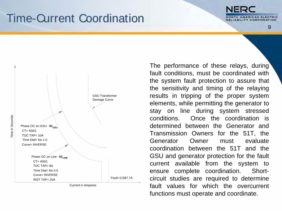
9TimeTime--Current CoordinationCurrent Coordination
GSU TransformerDamage Curve
Fault=11587.7A
Current in Amperes
Tim
e in
Sec
onds
Phase OC on GSU - 51GSUCT= 400/1TOC TAP= 10ATime Dial= No 1.0Curve= INVERSE
Phase OC on Line - 51LINE
CT= 400/1TOC TAP= 8ATime Dial= No 0.5Curve= INVERSEINST TAP= 20A
The performance of these relays, during fault conditions, must be coordinated with the system fault protection to assure that the sensitivity and timing of the relaying results in tripping of the proper system elements, while permitting the generator to stay on line during system stressed
conditions. Once the coordination is determined between the Generator and Transmission Owners for the 51T, the Generator Owner must evaluate coordination between the 51T and the GSU and generator protection for the fault current available from the system to ensure complete coordination. Short-
circuit studies are required to determine fault values for which the overcurrent functions must operate and coordinate.
10
System Events that Could Cause Undesired System Events that Could Cause Undesired Operation of These Protection FunctionsOperation of These Protection Functions
Fault Conditions
11
Seven Step Process for Seven Step Process for Functions 51T, 51TG (51G), and 50BFFunctions 51T, 51TG (51G), and 50BF
This is the process used throughout the coordination document to address each protective function as appropriate.
The following slides will take a step-by-step approach through the Functions 51T, 51TG (51G) and 50BF.
The next two slides provide the general data and information requirements from the Generator, Transmission, and Distribution Owners.
12
General Data Exchange Requirements General Data Exchange Requirements –– Generator Owner Data and InformationGenerator Owner Data and Information
The following general information must be exchanged in addition to relay settings to facilitate coordination, where applicable:•
Relay scheme descriptions•
Generator off nominal frequency operating limits•
CT and VT/CCVT configurations •
Main transformer connection configuration•
Main transformer tap position(s) and impedance (positive and zero sequence) and neutral grounding impedances
•
High voltage transmission line impedances (positive and zero sequence) and mutual coupled impedances (zero sequence)
•
Generator impedances (saturated and unsaturated reactances that include direct and quadrature axis, negative and zero sequence impedances and their associated time constants)
•
Documentation showing the function of all protective elements listed above

13
General Data Exchange Requirements General Data Exchange Requirements –– Transmission or Distribution Owner Data and InformationTransmission or Distribution Owner Data and Information
The following general information must be exchanged in addition to relay settings to facilitate coordination, where applicable:•
Relay scheme descriptions•
Regional Reliability Organization’s off-nominal frequency plan •
CT and VT/CCVT configurations•
Any transformer connection configuration with transformer tap position(s) and impedance (positive and zero sequence) and neutral grounding impedances
•
High voltage transmission line impedances (positive and zero sequence) and mutual coupled impedances (zero sequence)
•
Documentation showing the function of all protective elements•
Results of fault study or short circuit model•
Results of stability study•
Communication-aided schemes

14
Document Format Document Format –– Seven SubSeven Sub--Sections Sections for Each Protection Functionfor Each Protection Function
Purpose
Coordination of Generator and Transmission System•
Faults•
Loadability•
Other Conditions, Where Applicable
Considerations and Issues
Setting Validation for the Coordination•
Test Procedure for Validation •
Setting Considerations
Examples•
Proper Coordination•
Improper Coordination
Summary of Detailed Data Required for Coordination of the Protection Function
Table of Data and Information that Must be Exchanged

15
GSU Phase Overcurrent GSU Phase Overcurrent –– Function 51TFunction 51T GSU Ground Overcurrent GSU Ground Overcurrent –– Function 51TGFunction 51TG
Purpose•
Provide generator and GSU phase and ground backup protection for
uncleared system phase and ground faults.
GSU
F1
87T
F2
51TG
51T
50/5167I/T
or
50/51G
67GI/Tor
RATAuxiliaryPowerSystem
Figure 3.9.1 —
Phase & Ground Backup Overcurrent Relays on GSU Transformer
16
Coordination of Generator and Coordination of Generator and Transmission System Transmission System –– Functions 51T and 51TGFunctions 51T and 51TG
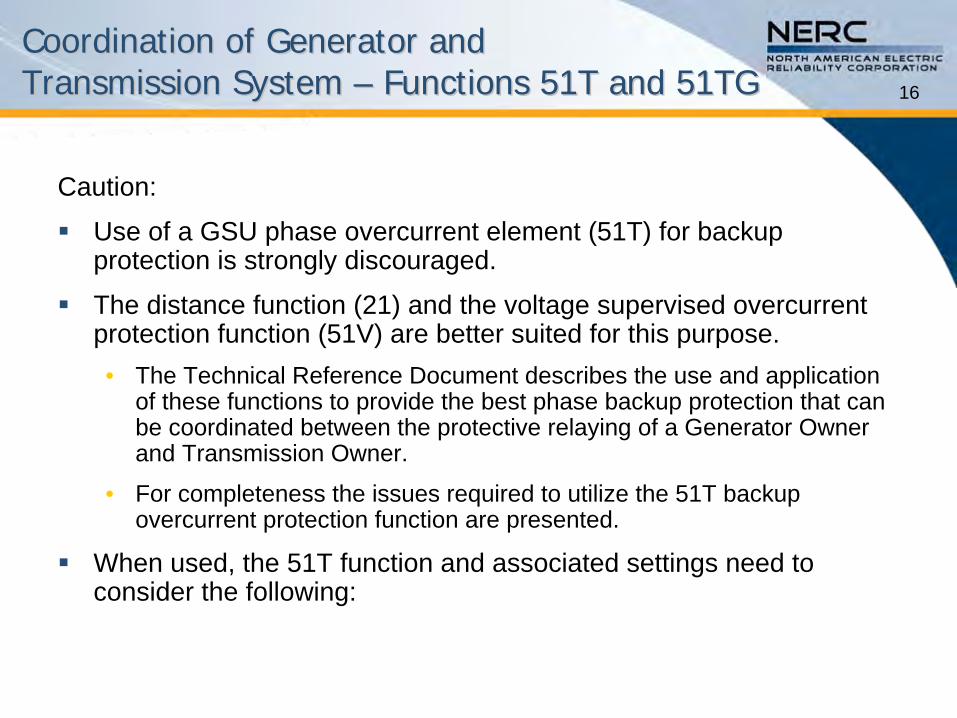
Caution:
Use of a GSU phase overcurrent element (51T) for backup protection is strongly discouraged.
The distance function (21) and the voltage supervised overcurrent protection function (51V) are better suited for this purpose.•
The Technical Reference Document describes the use and application of these functions to provide the best phase backup protection that can be coordinated between the protective relaying of a Generator Owner and Transmission Owner.
•
For completeness the issues required to utilize the 51T backup overcurrent protection function are presented.
When used, the 51T function and associated settings need to consider the following:
17
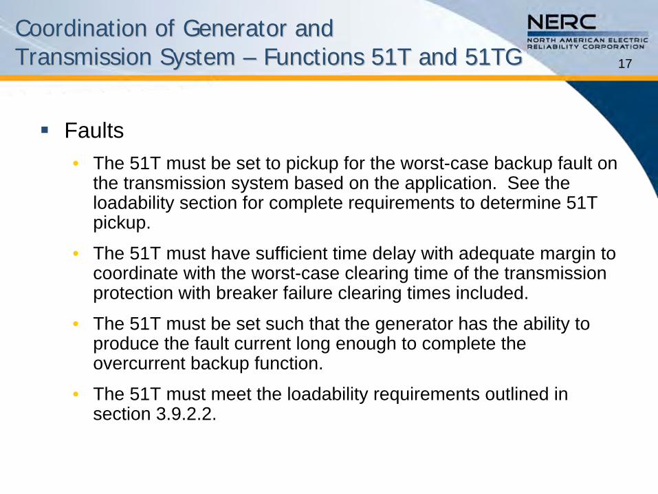
Faults•
The 51T must be set to pickup for the worst-case backup fault on the transmission system based on the application. See the loadability section for complete requirements to determine 51T pickup.
•
The 51T must have sufficient time delay with adequate margin to coordinate with the worst-case clearing time of the transmission protection with breaker failure clearing times included.
•
The 51T must be set such that the generator has the ability to produce the fault current long enough to complete the overcurrent backup function.
•
The 51T must meet the loadability requirements outlined in section 3.9.2.2.
Coordination of Generator and Coordination of Generator and Transmission System Transmission System –– Functions 51T and 51TGFunctions 51T and 51TG
18
Coordination of Generator and Coordination of Generator and Transmission System Transmission System –– Functions 51T and 51TGFunctions 51T and 51TG
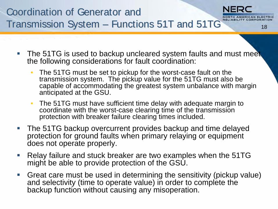
The 51TG is used to backup uncleared system faults and must meet
the following considerations for fault coordination:•
The 51TG must be set to pickup for the worst-case fault on the transmission system. The pickup value for the 51TG must also be
capable of accommodating the greatest system unbalance with margin anticipated at the GSU.
•
The 51TG must have sufficient time delay with adequate margin to
coordinate with the worst-case clearing time of the transmission protection with breaker failure clearing times included.
The 51TG backup overcurrent provides backup and time delayed protection for ground faults when primary relaying or equipment does not operate properly.
Relay failure and stuck breaker are two examples when the 51TG might be able to provide protection of the GSU.
Great care must be used in determining the sensitivity (pickup value) and selectivity (time to operate value) in order to complete the
backup function without causing any misoperation.
19
Coordination of Generator and Coordination of Generator and Transmission System Transmission System –– Functions 51T and 51TGFunctions 51T and 51TG
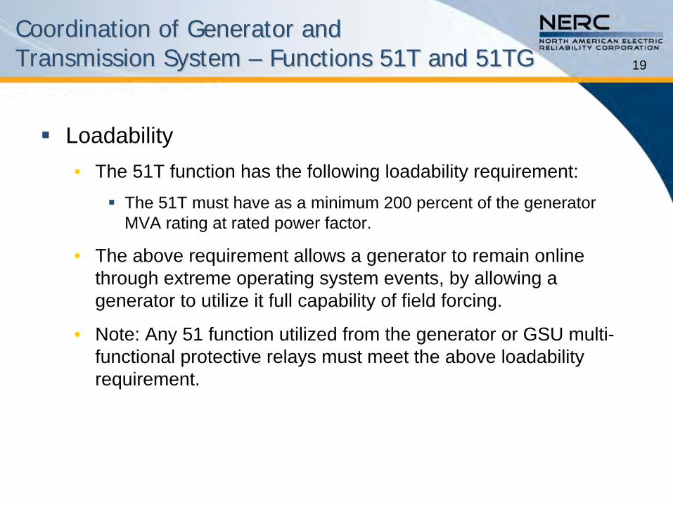
Loadability•
The 51T function has the following loadability requirement:
The 51T must have as a minimum 200 percent of the generator MVA rating at rated power factor.
•
The above requirement allows a generator to remain online through extreme operating system events, by allowing a generator to utilize it full capability of field forcing.
•
Note: Any 51 function utilized from the generator or GSU multi-
functional protective relays must meet the above loadability requirement.

20
Considerations and IssuesConsiderations and Issues –– Function 51T and 51TGFunction 51T and 51TG
Protective functions other than 51T are available to provide backup protection while providing better coordination with the transmission and generator protections.
The 51TG backup overcurrent provides backup and time delayed protection for ground faults when primary relaying or equipment does not operate properly.•
Relay failure and stuck breaker are examples when the 51TG might be able to provide protection for the GSU.
Refer to IEEE C37.102 section 4.6 and all subsections 4.6.1 –
4.6.4 for recommendations on setting the 21,
51V, and 51TG relays, and refer to the references in IEEE C37.102 that discourage the use of the 51T.

21
Coordination Procedure Coordination Procedure –– Function 51T and 51TGFunction 51T and 51TG
Coordination of Function 51T•
Function 51T must be set to the following requirements:
The 51T must have a minimum pickup of twice the generator MVA rating at rated power factor.
The 51T must operate slower, with margin, than the slowest transmission protection system that it must coordinate with based on protection design including breaker failure time.
The 51T must sense the required fault based on the transmission protection design with the fault current available from the generator in the time frame that it is set to operate.
The Generator Owner must determine that the setting for the 51T that coordinates with the transmission protection will also coordinate with the generator protection systems for the fault current available from the transmission system.

22
Coordination Procedure –– Function 51T and 51TGFunction 51T and 51TG
Coordination of Function 51TG •
Function 51TG must be set to the following requirements:
The 51TG must have a pickup with margin greater than the largest non-fault system unbalance anticipated based on system design.
The 51TG must operate slower with margin than the slowest transmission protection system that it must coordinate with based on protection design including breaker failure time.
23
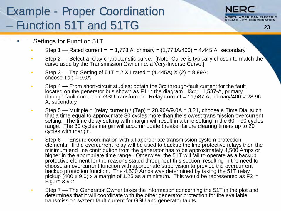
Settings for Function 51T•
Step 1 —
Rated current = = 1,778 A, primary = (1,778A/400) = 4.445 A, secondary •
Step 2 —
Select a relay characteristic curve. [Note: Curve is typically
chosen to match the curve used by the Transmission Owner i.e. a Very-Inverse Curve.]
•
Step 3 —
Tap Setting of 51T = 2 X I rated = (4.445A) X (2) = 8.89A; choose Tap = 9.0A
•
Step 4 —
From short-circuit studies; obtain the 3ф
through-fault current for the fault located on the generator bus shown as F1 in the diagram. I3ф=11,587-A, primary through-fault current on GSU transformer. Relay current = 11,587 A, primary/400 = 28.96 A, secondary
•
Step 5 —
Multiple = (relay current) / (Tap) = 28.96A/9.0A = 3.21, choose
a Time Dial such that a time equal to approximate 30 cycles more than the slowest
transmission overcurrent setting. The time delay setting with margin will result in a time setting in the 60 –
90 cycles range. The 30 cycles margin will accommodate breaker failure clearing timers up to 20 cycles with margin.
•
Step 6 —
Ensure coordination with all appropriate transmission system protection elements. If the overcurrent relay will be used to backup the line protective relays then the minimum end line contribution from the generator has to be approximately 4,500 Amps or higher in the appropriate time range. Otherwise, the 51T will fail to operate as a backup protective element for the reasons stated throughout this section, resulting in the need to choose an overcurrent function with appropriate supervision to provide the overcurrent backup protection function. The 4,500 Amps was determined by taking the 51T relay pickup (400 x 9.0) x a margin of 1.25 as a minimum. This would be represented as F2 in Figure 3.9.2.
•
Step 7 —
The Generator Owner takes the information concerning the 51T in
the plot and determines that it will coordinate with the other generator protection for the available transmission system fault current for GSU and generator faults.
Example Example -- Proper Coordination Proper Coordination –– Function 51T and 51TGFunction 51T and 51TG
24
Example Example -- Proper Coordination Proper Coordination –– Function 51T and 51TGFunction 51T and 51TG
GSU TransformerDamage Curve
Fault=11587.7A
Current in Amperes
Tim
e in
Sec
onds
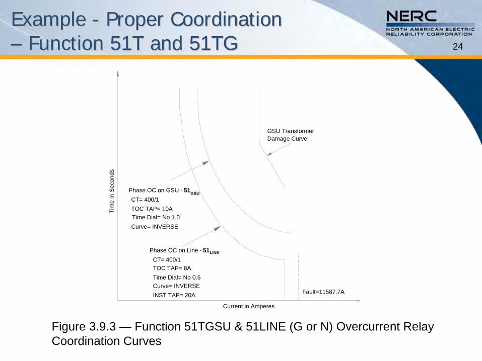
Phase OC on GSU - 51GSUCT= 400/1TOC TAP= 10ATime Dial= No 1.0Curve= INVERSE
Phase OC on Line - 51LINE
CT= 400/1TOC TAP= 8ATime Dial= No 0.5Curve= INVERSEINST TAP= 20A
Figure 3.9.3 —
Function 51TGSU & 51LINE (G or N) Overcurrent Relay Coordination Curves
25
Example Example -- Proper Coordination Proper Coordination –– Function 51T and 51TGFunction 51T and 51TG
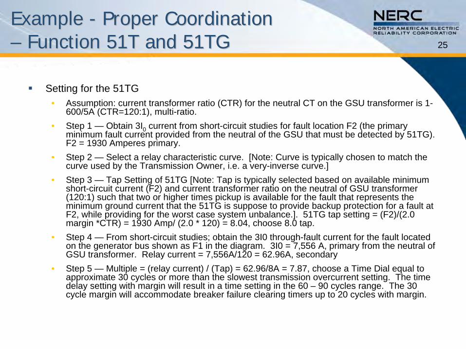
Setting for the 51TG •
Assumption: current transformer ratio (CTR) for the neutral CT on the GSU transformer is 1-
600/5A (CTR=120:1), multi-ratio.
•
Step 1 —
Obtain 3I0
current from short-circuit studies for fault location F2 (the primary minimum fault current provided from the neutral of the GSU that must be detected by 51TG). F2 = 1930 Amperes primary.
•
Step 2 —
Select a relay characteristic curve. [Note: Curve is typically
chosen to match the curve used by the Transmission Owner, i.e. a very-inverse curve.]
•
Step 3 —
Tap Setting of 51TG [Note: Tap is typically selected based on available minimum short-circuit current (F2) and current transformer ratio on the neutral of GSU transformer (120:1) such that two or higher times pickup is available for the fault that represents the minimum ground current that the 51TG is suppose to provide backup protection for a fault at F2, while providing for the worst case system unbalance.]. 51TG
tap setting = (F2)/(2.0 margin *CTR) = 1930 Amp/ (2.0 * 120) = 8.04, choose 8.0 tap.
•
Step 4 —
From short-circuit studies; obtain the 3I0 through-fault current for the fault located on the generator bus shown as F1 in the diagram. 3I0 = 7,556 A,
primary from the neutral of GSU transformer. Relay current = 7,556A/120 = 62.96A, secondary
•
Step 5 —
Multiple = (relay current) / (Tap) = 62.96/8A = 7.87, choose a Time Dial equal to approximate 30 cycles or more than the slowest transmission overcurrent setting. The time delay setting with margin will result in a time setting in the 60 –
90 cycles range. The 30 cycle margin will accommodate breaker failure clearing timers up
to 20 cycles with margin.
26
Example Example -- Proper Coordination Proper Coordination –– Function 51T and 51TGFunction 51T and 51TG
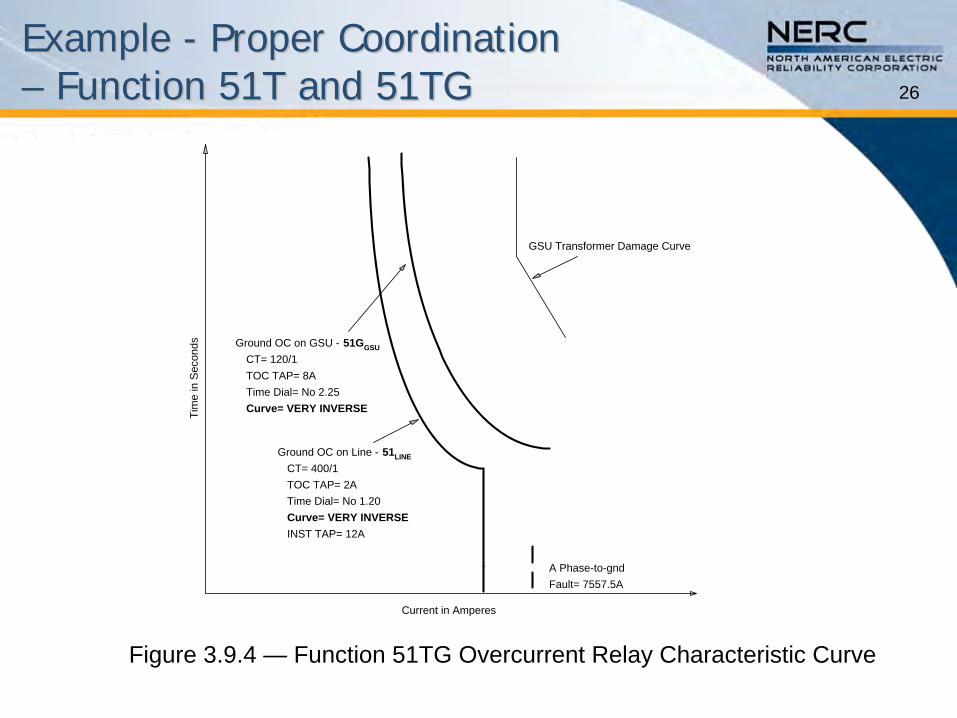
GSU Transformer Damage Curve
Ground OC on Line - 51LINE
CT= 400/1TOC TAP= 2ATime Dial= No 1.20Curve= VERY INVERSEINST TAP= 12A
Ground OC on GSU - 51GGSU
CT= 120/1TOC TAP= 8ATime Dial= No 2.25Curve= VERY INVERSE
Current in Amperes
Tim
e in
Sec
onds
Fault= 7557.5AA Phase-to-gnd
Figure 3.9.4 —
Function 51TG Overcurrent Relay Characteristic Curve

27
Example Example -- Improper Coordination Improper Coordination –– Function 51T and 51TGFunction 51T and 51TG
The miscoordination between the 51GLINE
(or 51NLINE
) and the 51GGSU
is due to the selection of dissimilar curves for one-on-
one coordination as was required in the above example.
51GLINE
is a very inverse curve and the 51GGSU
is an inverse curve.
GSU Transformer Damage Curve
Ground OC on Line - 51LINE
CT= 400/1TOC TAP= 2ATime Dial= No 1.20Curve= VERY INVERSEINST TAP= 12A
Ground OC on GSU - 51GGSU
CT= 120/1TOC TAP= 8ATime Dial= No 2.25Curve= INVERSE
Current in Amperes
Tim
e in
Sec
onds
Fault= 7557.5APhase-to-gnd
Use similar curves to fix the mis-coordination.
Figure 3.9.5 —
Mis-Coordination of 51GLINE
and 51GGSU
Settings
28
Summary of Protection Functions Required Summary of Protection Functions Required for Coordination for Coordination –– Function 51T and 51TGFunction 51T and 51TG
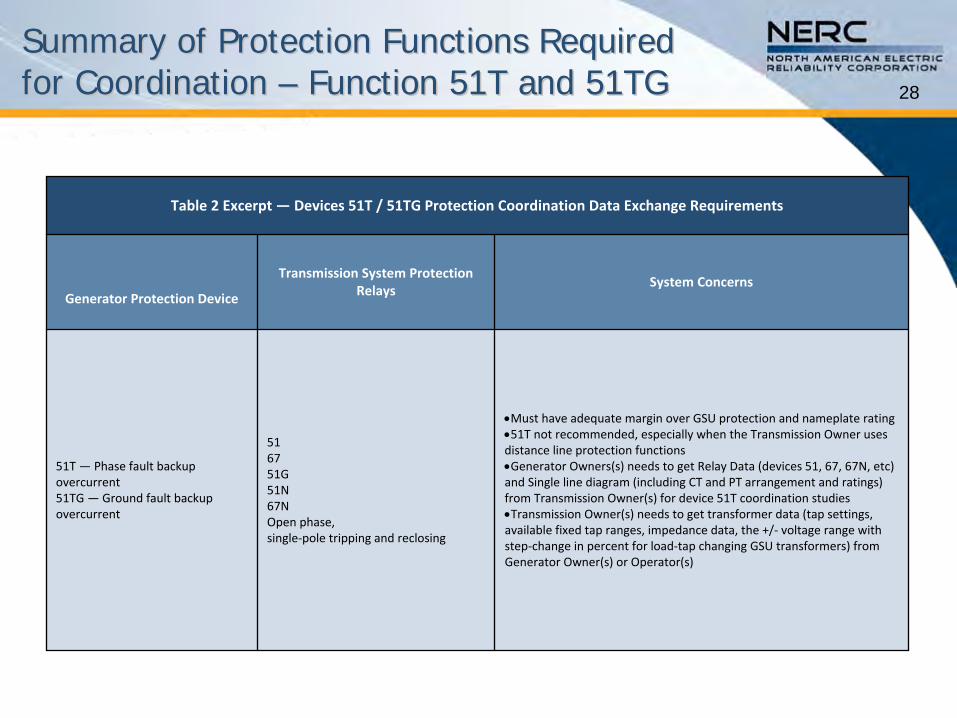
Table 2 Excerpt — Devices 51T / 51TG Protection Coordination Data Exchange Requirements
Generator Protection Device
Transmission System Protection
RelaysSystem Concerns
51T — Phase fault backup
overcurrent51TG —Ground fault backup
overcurrent
516751G 51N67NOpen phase, single‐pole tripping and reclosing
Must have adequate margin over GSU protection and nameplate rating51T not recommended, especially when the Transmission Owner uses
distance line protection functionsGenerator Owners(s) needs to get Relay Data (devices 51, 67, 67N, etc)
and Single line diagram (including CT and PT arrangement and ratings)
from Transmission Owner(s) for device 51T coordination studiesTransmission Owner(s) needs to get transformer data (tap settings,
available fixed tap ranges, impedance data, the +/‐
voltage range with
step‐change in percent for load‐tap changing GSU transformers) from
Generator Owner(s) or Operator(s)

29
Protection Function Data and Information Exchange Protection Function Data and Information Exchange Required for Coordination Required for Coordination –– Functions 51T and 51TGFunctions 51T and 51TG
Table 3 Excerpt — Devices 51T / 51TG Data To be Provided
Generator Owner Transmission Owner Planning Coordinator
Relay settings Device 51T
— Phase fault backup overcurrentDevice 51TG
—Ground fault backup overcurrent
One line diagram of the transmission system up
to one bus away from the generator high‐side
bus.
Feedback on coordination problems found in
stability studies.
Relay timer settings.Impedances of all transmission elements
connected to the generator high‐side bus.
Total clearing times for the generator breakers.Relay settings on all transmission elements
connected to the generator high‐side bus.
NoneTotal clearing times for all transmission elements
connected to the generator high‐side bus.
NoneTotal clearing times for breaker failure, for all
transmission elements connected to the
generator high‐side bus.

30
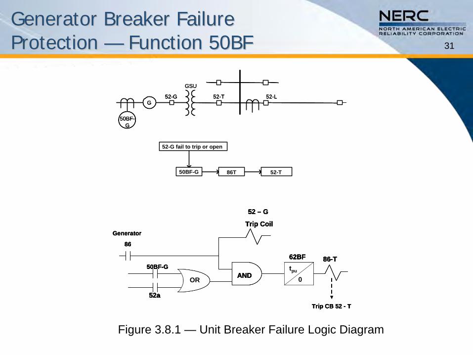
Generator Breaker Failure Generator Breaker Failure Protection Protection —— Function 50BFFunction 50BF
Purpose•
Breaker failure protection must be provided for large generators such that the generator is isolated in the event when its breakers fail to open subsequent to receiving a signal to trip.
•
When a generator unit breaker fails, it is required to initiate the tripping of backup breaker(s) for isolation of the failed breaker.
31
Generator Breaker Failure Generator Breaker Failure Protection Protection —— Function 50BFFunction 50BF
50BF-G 86T 52-T
52-G fail to trip or open
GSU
52-G 52-LG
52-T
50BF-G
50BF-G
52a
Generator
86
86-T
52 – G
Trip Coil
tpu
0
Trip CB 52 - T
62BF
OR AND50BF-G
52a
Generator
86
86-T
52 – G
Trip Coil
tpu
0
Trip CB 52 - T
62BF
OR AND
50BF-G 86T 52-T
52-G fail to trip or open
GSU
52-G 52-LG
52-T
50BF-G
50BF-G 86T 52-T
52-G fail to trip or open
GSU
52-G 52-LG
52-T
50BF-G
50BF-G
52a
Generator
86
86-T
52 – G
Trip Coil
tpu
0
Trip CB 52 - T
62BF
OR AND50BF-G
52a
Generator
86
86-T
52 – G
Trip Coil
tpu
0
Trip CB 52 - T
62BF
OR AND
Figure 3.8.1 —
Unit Breaker Failure Logic Diagram

32
Coordination of Generator and Coordination of Generator and Transmission System Transmission System –– Function 50BFFunction 50BF
Faults•
The following coordination issues must be addressed:
Transmission Owner and Generator Owner verify that breaker failure time is accounted for properly for each set of relay coordination.
For example,–
All generator unit backup relaying schemes are required to coordinate with protective relays on the next zone of protection including their breaker failure relaying time.
–
For obtaining the security and reliability of power system stability, Generator Owner and Transmission Owner(s) are required to coordinate, plan, design, and test the scheme.
–
There must be design coordination to assure that appropriate backup breakers are tripped for breaker failure operation.
Loadability•
There are no coordination issues related to loadability for this
function.
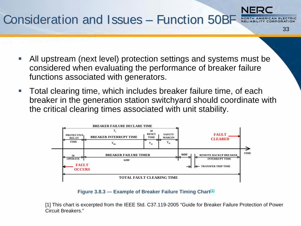
33Consideration and Issues Consideration and Issues –– Function 50BFFunction 50BF
All upstream (next level) protection settings and systems must be considered when evaluating the performance of breaker failure functions associated with generators.
Total clearing time, which includes breaker failure time, of each breaker in the generation station switchyard should coordinate with the critical clearing times associated with unit stability.
TOTAL FAULT CLEARING TIME
FAULTCLEARED
FAULTOCCURS
TIME
PROTECTIVERELAYTIME
BREAKER FAILURE TIMER 86BF
TRANSFER TRIP TIME
REMOTE BACKUP BREAKERINTERRUPT TIME
BREAKER FAILURE DECLARE TIME
BREAKER INTERRUPT TIMESAFETYMARGIN
TM
50OPERATE
50RESETTIME
T50
T1
TBK
62BF
Figure 3.8.3 — Example of Breaker Failure Timing Chart[1]
[1] This chart is excerpted from the IEEE Std. C37.119-2005 “Guide for Breaker Failure Protection of Power Circuit Breakers.”

34
Coordination of Generator and Coordination of Generator and Transmission System Transmission System –– Function 50BFFunction 50BF
The following are examples of Breaker Failure Timer Settings (62BF) of a Breaker Failure Scheme for typical three-cycle and five-cycle breakers.
Breaker Failure Timer = Breaker Interrupting Time +50 Reset Time + Safety Margin
Three-Cycle Breaker•
62BF = TBK + T50 + TM
= 3.0 + 1.55 + 5.0 = 9.55 cycles or 159 milliseconds
Five-Cycle Breaker•
62BF = TBK + T50 + TM
= 5.0 + 1.55 + 5.0 = 11.55 cycles or 193 milliseconds

35Coordination ProcedureCoordination Procedure
Setting Considerations•
Total clearing time, which includes breaker failure time, of each breaker in the generation station switchyard should coordinate with the critical clearing times associated with unit stability.
•
To provide proper Breaker Failure (BF) protection, the following
should be considered:
See C37.119 “IEEE Guide for Breaker Failure Protection of Power Circuit Breakers”
for a well-designed breaker failure scheme.
Clearing time issues are addressed further in Sections 4.7 and A.2.11 of C37.102-2006 —
Guide for AC Generator Protection.
Refer to Section 3.1 of the Technical Reference Document for coordination of upstream protective function 21 with the breaker
failure scheme.

36
Example Example -- Proper Coordination Proper Coordination –– Function 50BFFunction 50BF
This example addresses coordination with line relaying and line breaker failure conditions.
GSU
GSUBF
BF
Z11
2
5
3G1
G2
BF
BF
BF4
FAULTLOCATION
21
BF
21
BFTT TT
6
BF
21
21
Figure 3.8.6 — Case-1 – Breaker Failure Coordination
37
Example Example –– Improper Coordination Improper Coordination –– Function 50BFFunction 50BF
Improper Coordination •
Improper coordination results when upstream protective functions react faster than the breaker failure function.

38
Summary of Protection Functions Summary of Protection Functions Required for Coordination Required for Coordination –– Function 50BFFunction 50BF
Table 2 Excerpt — Device 50BF Protection Coordination Data Exchange Requirements
Generator Protection Device
Transmission System Protection
RelaysSystem Concerns
50BF — Breaker failure (plant) on
synchronizing breaker(s)
Critical clearing times from system
stability studies50BF on line(s) & buses
Check for single‐points‐of‐failure
Current and 52a contact considerations
Critical clearing time
Coordination with zone 2 and zone 3 timers
Settings should be used for planning and system studies
Line distances relay reach and time delay settings with respect to
each generator zone.
Bus differential relay (usually instantaneous) timing for HV bus
faults including breaker failure adjacent bus.
Line and Bus Breaker failure timers and line zone 1 and zone 2
timers on all possible faults.
Type of protective relays, Manufacturers, Models, etc.
Single line diagram(s) including CTs and VTs arrangement
PCB test data (interrupting time)

39
Protection Function Data and Information Protection Function Data and Information Exchange Required for Coordination Exchange Required for Coordination –– Function 50BFFunction 50BF
Table 3 Excerpt — Device 50BF Data To be Provided
Generator Owner Transmission Owner Planning Coordinator
Times to operate of generator protection Breaker Failure Relaying times
Times to operate, including timers, of
transmission system protectionBreaker Failure Relaying times
None

40What is Important to CoordinationWhat is Important to Coordination
•
Settings that Protect the Generator
•
Coordination Margin
41Settings that Protect the GeneratorSettings that Protect the Generator
The protection set-points for Functions 51T, 51TG (51G), and 50BF are described in:•
C37.102 “IEEE Guide for AC Generator Protection”•
C37.91 “IEEE Guide for Transformer Protection”•
C37.119 “IEEE Guide for Breaker Failure Protection of Power Circuit Breakers”
The time-current characteristics, current detector level, and time delay are adjusted based on the specific generator, transformer, breakers, and system application.
Examples of these were given in the presentation, but again, specific settings need to be determined and coordinated by the entities.

42Coordination MarginCoordination Margin
Examples of these were given in the presentation, but again, specific settings need to be determined and coordinated by the entities.
