system for engine location of the webtrain adam weintrop and paul wimmer advisors dr. irwin and dr....
Post on 22-Dec-2015
214 views
TRANSCRIPT
System for Engine Location of the
WebTrain
Adam Weintrop and Paul WimmerAdvisors
Dr. Irwin and Dr. Schertz

2
3
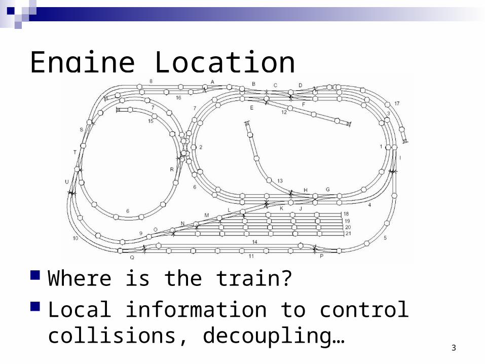
Engine Location
Where is the train? Local information to control collisions,
decoupling…

4
Outline
Summary Schedule Functional Description Block Diagram Goals for end of project

5
Project Summary
Had to recreate train command control system
Using current sensing – train location can be determined quickly
Microprocessor can control train functions using location information

6
Train Control System
3 Level MenuTrain ChoiceSpeed Choice
Using 10 different speeds to test full range
Direction Choice Forwards / Backwards
Sends command then “long zeroes”

7
Outline
Summary Schedule Functional Description Block Diagram Goals for end of project

8
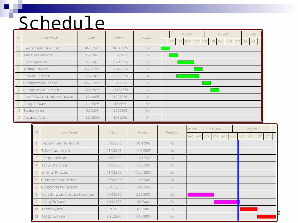
Schedule
ID Task Name Start Finish DurationJan 2006 Mar 2006Feb 2006
3/193/5 3/121/29 2/19 2/261/22 2/5 3/262/12
1 1w10/31/200510/25/2005Explore Current Web Train
2 1w11/7/200511/1/2005Take Measurements
3 2w11/21/200511/8/2005Design Hardware
4 1w11/28/200511/22/2005Testing Hardware
5 3w11/25/200511/7/2005Software Research
6 1w12/5/200511/29/2005Microprocessor Decision
7 1w12/12/200512/6/2005Microprocessor Research
8 3w2/13/20061/24/2006Code Software / Interface Hardware
9 3w3/6/20062/14/2006Debug Software
2w3/20/20063/7/2006Testing system
11
10
3w4/10/20063/21/2006Additional Tasks
9
ScheduleID Task Name Start Finish Duration
Dec 2005 Jan 2006Nov 2005
12/1812/4 12/1110/30 11/20 11/27 1/111/6 1/812/2511/13
1 1w10/31/200510/25/2005Explore Current Web Train
2 1w11/7/200511/1/2005Take Measurements
3 2w11/21/200511/8/2005Design Hardware
4 1w11/28/200511/22/2005Testing Hardware
5 3w11/25/200511/7/2005Software Research
6 1w12/5/200511/29/2005Microprocessor Decision
7 1w12/12/200512/6/2005Microprocessor Research
8 3w2/13/20061/24/2006Code Software / Interface Hardware
9 3w3/6/20062/14/2006Debug Software
2w3/20/20063/7/2006Testing system
11
10
3w4/10/20063/21/2006Additional Tasks
ID Task Name Start Finish DurationJan 2006 Mar 2006Feb 2006
3/193/5 3/121/29 2/19 2/261/22 2/5 3/262/12
1 1w10/31/200510/25/2005Explore Current Web Train
2 1w11/7/200511/1/2005Take Measurements
3 2w11/21/200511/8/2005Design Hardware
4 1w11/28/200511/22/2005Testing Hardware
5 3w11/25/200511/7/2005Software Research
6 1w12/5/200511/29/2005Microprocessor Decision
7 1w12/12/200512/6/2005Microprocessor Research
8 3w2/13/20061/24/2006Code Software / Interface Hardware
9 3w3/6/20062/14/2006Debug Software
2w3/20/20063/7/2006Testing system
11
10
3w4/10/20063/21/2006Additional Tasks
10
Outline
Summary Schedule Functional Description Block Diagram Goals for end of project
11
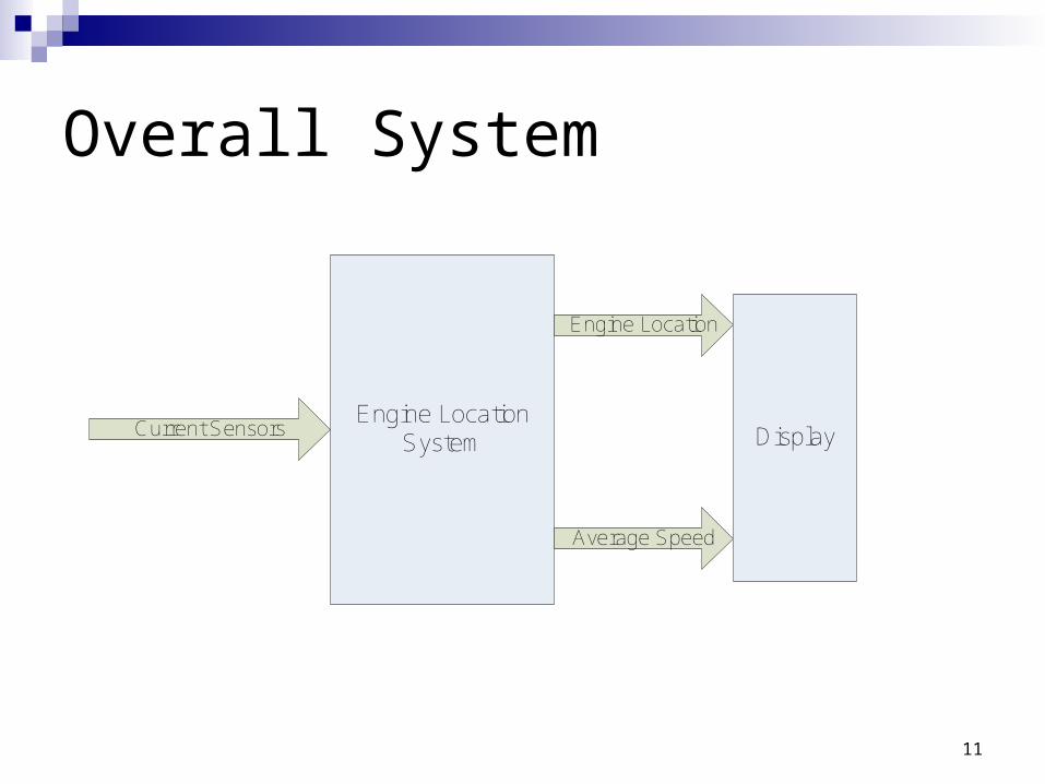
Overall System
Engine Location System
Current Sensors
Engine Location
Average Speed
Display
12
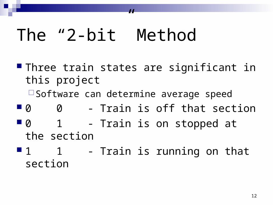
The “2-bit” Method
Three train states are significant in this project Software can determine average speed
0 0 - Train is off that section 0 1 - Train is on stopped at the section 1 1 - Train is running on that section

13
Outline
Summary Schedule Functional Description Block Diagram Goals for end of project

14
Block Diagram
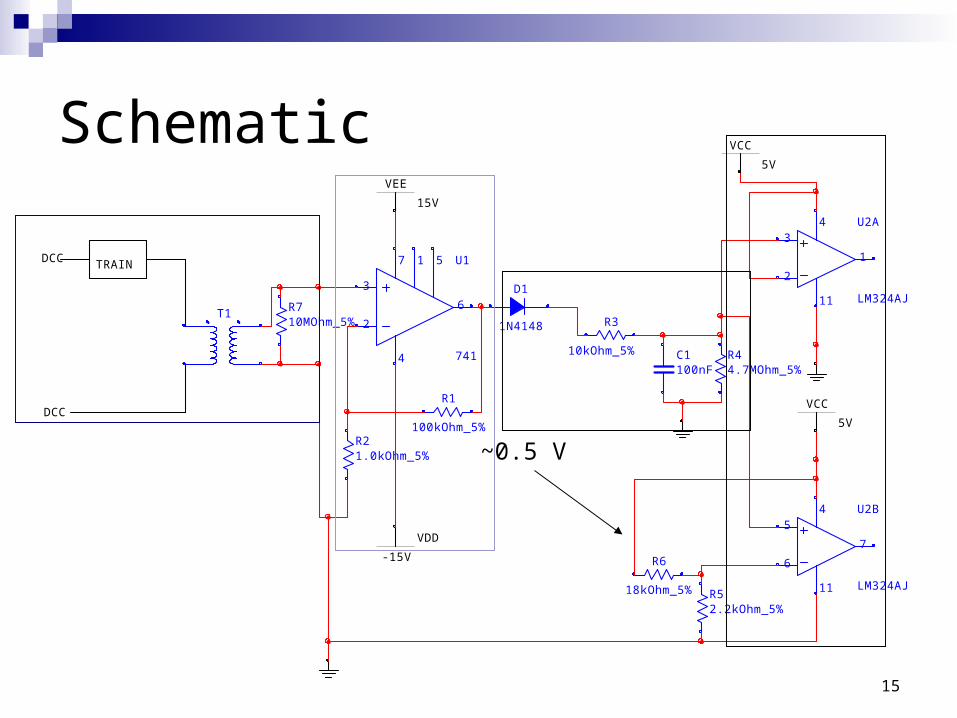
Current Transformers
High Gain Amplifier
Rectifier Filter
Comparator for detection of a moving train
Comparator for Idle detection
Multiplexers Microcontroller
15
R1
100kOhm_5%R21.0kOhm_5%
VEE
15V
DCC
DCC
TRAIN
T1
U1
741
3
2
4
7
6
51
VDD
-15V
U2A
LM324AJ
3
2
11
4
1
R3
10kOhm_5% R44.7MOhm_5%
C1100nF
U2B
LM324AJ
5
6
11
4
7
VCC
5V
R52.2kOhm_5%
R6
18kOhm_5%
R710MOhm_5%
D1
1N4148
VCC
5V
Schematic
~0.5 V

16
Outputs of HardwareOFF TRACK
RUNIDLE
High is >4.35VLow is <40 mV
17
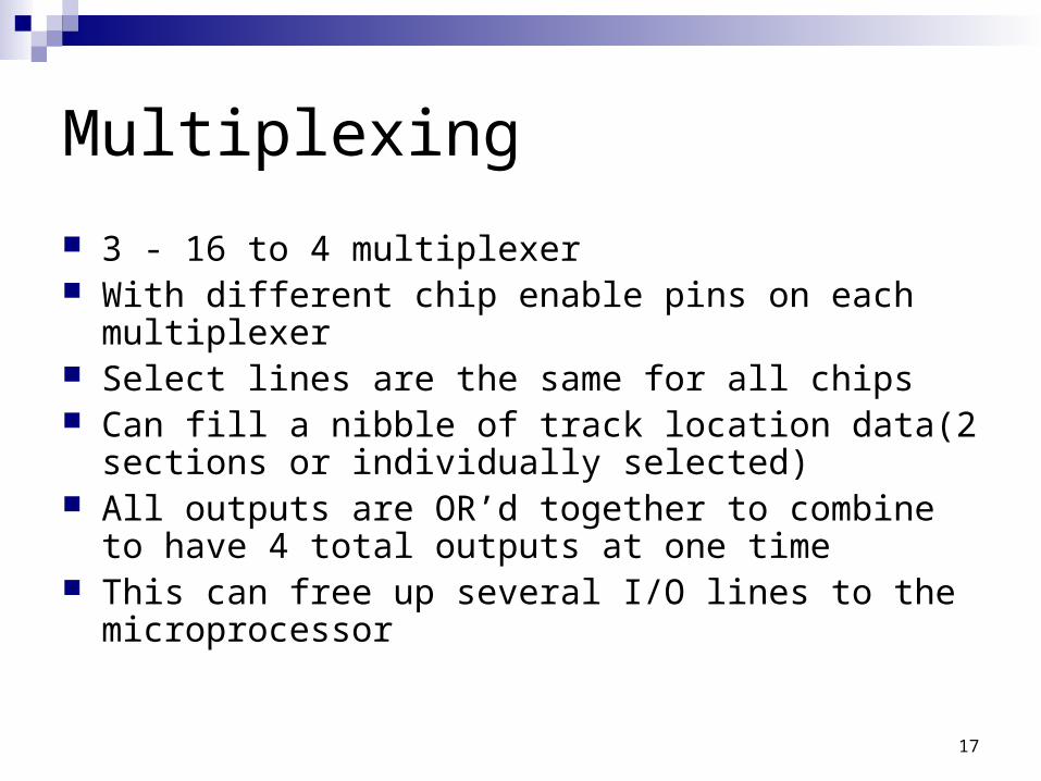
Multiplexing
3 - 16 to 4 multiplexer With different chip enable pins on each multiplexer Select lines are the same for all chips Can fill a nibble of track location data(2 sections or
individually selected) All outputs are OR’d together to combine to have 4 total
outputs at one time This can free up several I/O lines to the microprocessor

18
Software
Using C code on 80535 Want to take information of train status
and location and process Output where train is, status, and
implement warnings of collision First step to more advanced software

19
Flow ChartControl the MUX Chip enable and
Select Inputs
Check the MUX outputs
Determine if the location of the train
has changed
Stop and Start a timer to determine how long the train took to cross the
last section
YE
S
Determine the location of the
train(s)
Lookup how far the train traveled and
direction (CW/CCW) based on old and
new positions (sometimes direction)
Compute velocity
Store the old and new locations of
the train
Basic collision avoidance check?
Relay position/collision
information to the PC?

20
Outline
Summary Schedule Functional Description Block Diagram Goals for end of project
21
Plan for Rest of Semester
LED board to show train location and status
We will have completed the software in 1 week and the rest of the semester will be devoted to testing
22
Conclusion
With hardware built and software designed, engine location system is near completion
Questions?

23
Questions? – We have answers
A/D method?Need precise A/DAnalog multiplexingBut a train with a heavy load could look like a
faster train

24
More Answers
Nonlinear amplifier?More complex than necessaryCan be substituted for high gain amplifier in
current system

25
Other Scope Plots
Idle on track after amplifier Idle on track after rectifier / filter ~1 V
26
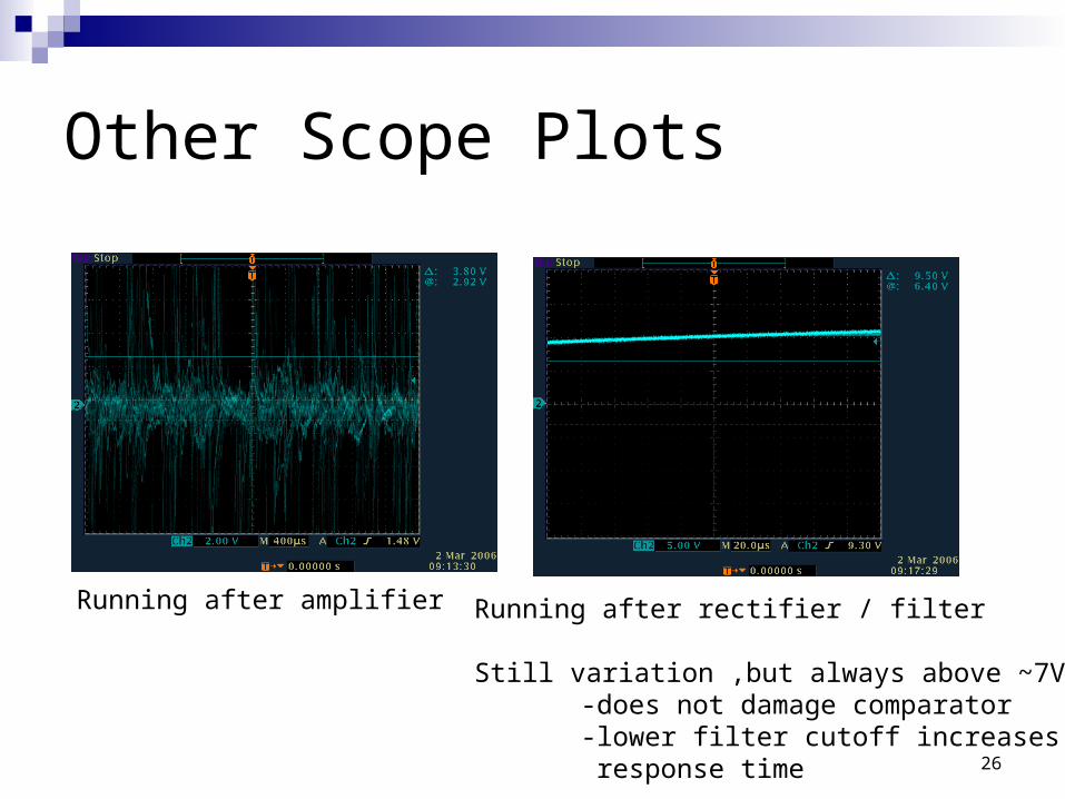
Other Scope Plots
Running after amplifier Running after rectifier / filter
Still variation ,but always above ~7V-does not damage comparator-lower filter cutoff increases response time