synthesis of magneto-dielectrics from first principles … · synthesis of magneto-dielectrics from...
TRANSCRIPT
Synthesis of Magneto-Dielectrics from First Principles and Antenna Design
Kyu Han1,2, Madhavan Swaminathan1,2, P. Markondeya Raj3, Himani Sharma3, Rao Tummala3,
Brandon Rawlings4, Songnan Yang4 and Vijay Nair4 1Interconnect and Packaging Center (IPC), SRC Center of Excellence @ GT
2School of Electrical and Computer Engineering, Georgia Institute of Technology
266 Ferst Drive, Atlanta, GA 30332 USA
Email: [email protected] 3Packaging Research Center, Georgia Institute of Technology
4Intel Corporation, Chandler, Arizona
Abstract
Magneto-dielectric materials have been spotlighted as a
new opportunity for effective antenna size reduction in many
recent studies. In this paper, we start from first principles to
describe the methodology used to synthesize the magneto-
dielectric material. A combination of Bruggeman’s effective
medium model and Sihvola and Lindell model are used to find
the right mixture of cobalt particles and fluoropolymer
material for the effective antenna miniaturization. A three
pole Lorentzian dispersion model is derived for fitting
extracted material properties of magneto-dielectric composite
material. The material properties are extracted using a cavity
perturbation technique with substrate integrated waveguide
cavity resonator. The Kramers-Kronig relations are used to
demonstrate that the extracted material properties from the
method are causal in this paper. A 900MHz PIFA on
magneto-dielectric material substrate is designed, fabricated
and measured. A 7.4% bandwidth and 61.7% radiation
efficiency for the antenna were obtained. Human body effect
to antenna was studied and Specific Absorption Rate (SAR)
was calculated. The simulation results show that magneto-
dielectric material can reduce the effect of human body on
antenna performance and the magnetic loss enables a decrease
in the SAR of the antenna.
Introduction
Antenna size is a big concern for mobile device developers
because the antenna size is determined by its electrical length
and also antenna performance is directly related to the size.
Various methods have been studied and one method is to
reduce the antenna size by increasing the refractive index
(n=(εr·μr)½ ) of the material where εr and µ r are relative
permittivity and permeability respectively. Magneto-dielectric
(MD) materials, which have µ r greater than unity, as
compared to high dielectric constant materials, provide
several advantages for antenna design, especially when the
antenna needs to be miniaturized [1]. Recently we reported
MD material which is synthesized using cobalt-fluoropolymer
with relative permittivity=8, relative permeability=2, electric
loss tangent=0.0024 and magnetic loss tangent=0.068 at
1GHz [2]. These are the best reported to date in the open
literature using metal-polymer composites.
MD materials are realized through material synthesis and
many mixing rules, which determine the properties of the
material synthesized, are available. In this paper, some of the
mixing rules are applied and the right mixture of cobalt
particles and fluoropolymer materials are derived to obtain the
properties described earlier. As an extension of [2], causality
of the measured MD material properties was investigated.
According to Kramers-Kronig relations [3], the real and
imaginary parts of the electrical material properties are related
to each other. The Kramers-Kronig relations should be
satisfied for the extracted material properties to verify that
they are causal. Sum of three resonance terms based on the
Lorentzian dispersion law [4] was used to fit the measured
data and the causality of the material property has been
demonstrated using the Kramers-Kronig relations.
Based on the properties of the material synthesized, an
antenna on MD material was designed to show its
performance using both modeling and measurements at RF
frequencies. Preliminary investigations on antenna design
using this MD material was discussed in [5]. As an extension
of [6], the antenna described is a meander PIFA antenna
operating in the GSM-900 band. Even with a magnetic loss
tangent of 0.068 at 1GHz, small antennae can be designed
with reasonably good gain, bandwidth and efficiency.
Furthermore, the loss characteristics of MD composite
material can help reduce specific absorption rate (SAR). To
reduce SAR of antenna, EBG structures beneath the antenna
have been introduced [7]. In this paper, the natural properties
of the MD material help reduce SAR.
Effective Material Properties
The magneto-dielectric material composite which is not
readily available in nature is realized though material
synthesis. ‘Effective medium theories’ (EMTs) or mixing
rules are used to predict the properties of composites from its
components. In this paper, cobalt nano particles were mixed
with fluoropolymer to synthesize the MD material for antenna
application. There are numerous theories and models that
estimate permittivity and permeability of mixed composites.
For the effective permittivity prediction, Sihvola and
Lindell’s mixing rule for an N-layer spherical filler particle, in
which the Rayleigh mixing formula is generalized to deal with
layered filler particles, is used [8]. Cobalt-fluoropolymer
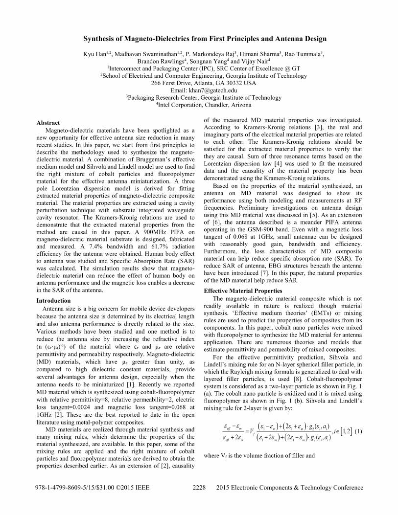
system is considered as a two-layer particle as shown in Fig. 1
(a). The cobalt nano particle is oxidized and it is mixed using
fluoropolymer as shown in Fig. 1 (b). Sihvola and Lindell’s
mixing rule for 2-layer is given by:
1 1 2
1 1 2
2 ( , ), 1, 2
2 2 2 ( , )
eff m m m i i
f
eff m m m i i
g aV i
g a
(1)
where Vf is the volume fraction of filler and
978-1-4799-8609-5/15/$31.00 ©2015 IEEE 2228 2015 Electronic Components & Technology Conference
3
2 1 2
2
2 1 1
.2
ag
a
(2)
This equation can be simplified for εeff as:
1 2,
1
m
eff
A
A
(3)
where A is the right term in (1). Permittivity of cobalt-oxide
and fluoropolymer were assumed as 10.9 (ε1) and 2 (εm)
respectively. Drude model was used for the permittivity of
cobalt (ε2) as:
2
0
1 ,j
(4)
where σ is the conductivity which is 1.6e6s/m for the cobalt
particle, ω and ε0 are angular frequency and permittivity of
free space, respectively.
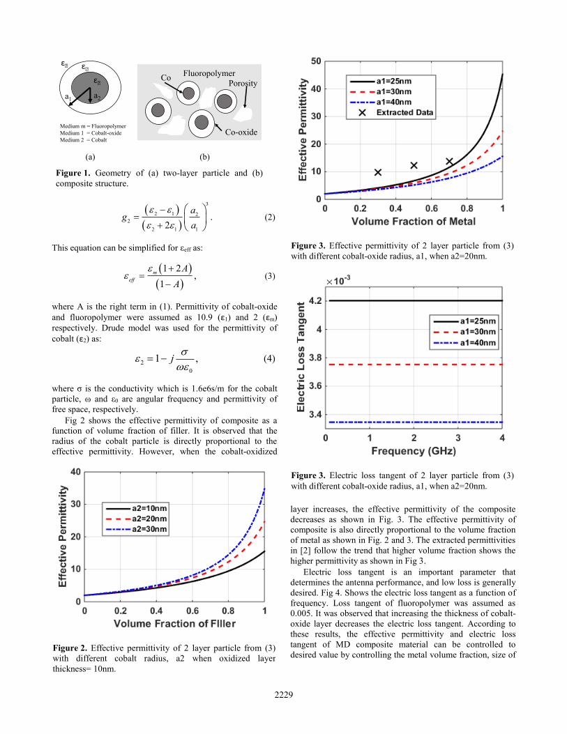
Fig 2 shows the effective permittivity of composite as a
function of volume fraction of filler. It is observed that the
radius of the cobalt particle is directly proportional to the
effective permittivity. However, when the cobalt-oxidized
layer increases, the effective permittivity of the composite
decreases as shown in Fig. 3. The effective permittivity of
composite is also directly proportional to the volume fraction
of metal as shown in Fig. 2 and 3. The extracted permittivities
in [2] follow the trend that higher volume fraction shows the
higher permittivity as shown in Fig 3.
Electric loss tangent is an important parameter that
determines the antenna performance, and low loss is generally
desired. Fig 4. Shows the electric loss tangent as a function of
frequency. Loss tangent of fluoropolymer was assumed as
0.005. It was observed that increasing the thickness of cobalt-
oxide layer decreases the electric loss tangent. According to
these results, the effective permittivity and electric loss
tangent of MD composite material can be controlled to
desired value by controlling the metal volume fraction, size of
Figure 2. Effective permittivity of 2 layer particle from (3)
with different cobalt radius, a2 when oxidized layer
thickness= 10nm.
Figure 1. Geometry of (a) two-layer particle and (b)
composite structure.
a2a1
ε2
ε1εm
Medium m = Fluoropolymer
Medium 1 = Cobalt-oxide
Medium 2 = Cobalt
Co
Co-oxide
Fluoropolymer
Porosity
(a) (b)
Figure 3. Effective permittivity of 2 layer particle from (3)
with different cobalt-oxide radius, a1, when a2=20nm.
Figure 3. Electric loss tangent of 2 layer particle from (3)
with different cobalt-oxide radius, a1, when a2=20nm.
2229

the metal particle, its oxidization thickness and dielectric
constant and loss tangent of the polymer matrix.
For effective permeability modeling, one of the most
common mixing rules, Bruggeman’s effective medium theory
is used [9], which is given by:
1
1 0,2 1 2
a eff eff
f f
a eff eff
V V
(5)
where μa is the intrinsic permeability and (4) can be simplified
for μeff as:
2 ,2
3 3 2.
4
aeff
f a f aV V
(6)
The permeabilities of composite material for various intrinsic
permeabilities are shown in Fig. 5. The extracted
permeabilities in [2] coincide with the curve having an
intrinsic permeability of 4.
To maximize the benefits of MD composite material for
antenna application, high permeability is necessary, while the
permittivity should be low enough to increase μr/εr ratio. The
effective permittivity can be reduced using a low-permittivity
polymer matrix and small metal particles. Since increasing the
metal volume fraction in the composite increases both
effective permittivity and permeability, moderate filler
volume fraction is required. A 40~60% volume fraction of
cobalt filler can give good material properties for the RF
antenna application according to design guidelines obtained
from modeling.
Material Property Modeling
In [5], the cavity perturbation technique (CPT) with
substrate integrated waveguide (SIW) cavity resonator was
used to extract the MD material properties. This method can
extract both electric and magnetic property of MD material
using a single resonator by changing the sample insertion
location. The extracted MD composite material properties
from CPT with SIW were obtained at discrete frequency
points. Extrapolation of the data would be necessary to
estimate the material properties outside of the frequency range
measured for analyzing the performance of the antenna. The
Lorentzian dispersion law describes the frequency-dependent
permittivity and permeability for a single component material
as [4]:
2
,1 d r
AA A
i f f f f
(7)
where A represents either εr or μr and f is the frequency.
Parameters fd and fr are Debye and resonance characteristic
frequencies, respectively, that determine the location of the
electric/magnetic loss peak and the shape of the
electric/magnetic dispersion curve [9]. The value of ΔA’=As-
A’∞, where As and A’∞ are the static value of A and value of
A in the optic region respectively.
Most synthesized MD composite materials, however, do
not follow the Lorentzian dispersion model with a single
resonance term due to inhomogeneity of particles inside of the
composite and several different physical mechanisms
contribute to the dispersion in MD composite materials.
Therefore, the electric and magnetic dispersion curve can be
expressed as a sum of several resonance terms [10]. In order
to fit the extracted material properties in [2], the sum of three
resonances is chosen. Three pole Lorentzian dispersion model
can be written as:
1
2
1 1
2
2
2 2
3
2
3 3
1
1
.1
r d
r d
r d
AA A
f f j f f
A
f f j f f
A
f f j f f
(8)
Before using (8) to fit the extracted MD composite material
properties, the three pole Lorentzian dispersion model should
be checked for causality; otherwise, the model can be
noncausal and provide inaccurate results [11]. The causality
of the model can be verified using Kramers-Kronig relations,
which describes a direct relation between real and imaginary
part of permittivity/permeability. According to the Kramers-
Kronig relations, the real part and imaginary part of
permittivity/permeability are related by [3]:
0 2 2
00
2,
f X f dfX f P
f f
(9)
00 2 2
00
2,
X f dffX f P
f f
(10)
Figure 5. Effective permeability of composite from (6) with
different intrinsic permeabilities.
2230

where P is the Cauchy principle value. Fig 6 and 7 show the
real and imaginary parts of A calculated using (9) and (10).
The results from the Kramers-Kronig relations and analytic
solutions show good correlation, indicating that the three pole
Lorentzian dispersion model satisfies causality.
The extracted permittivity and permeability values of MD
material in [2] were fitted using the three pole Lorentzian
dispersion model as shown in Fig. 8 and 9. The unknown
parameters in (8) were found empirically. As shown in the
figures, the extracted material properties for 30%, 50% and
70% metal loading samples show good correlation with the
three pole Lorentzian dispersion model at discrete
frequencies.
Antenna Design on MD Composite Material
A 900MHz Planar Inverted-F antenna (PIFA) on MD
composite material substrate was designed as shown in Fig.
10. Cobalt nano-particles were mixed with fluoropolymer to
realize MD material and its properties were measured using
CPT with SIW cavity resonator method described in [2]. The
relative permittivity and permeability of the MD composite
material used were 8 and 2 at 900MHz respectively. Also
electric loss tangent and magnetic loss tangent used were
0.0024 and 0.068 at 900MHz respectively. A FR4 PCB with a
relative permittivity of 4.3 and electric loss tangent of 0.02
was used as a ground plane to support MD material substrate.
The size of the MD material substrate was 20 x 20 x 1.5mm3
and the overall dimension of the PCB was 60 x 120 x 1mm3.
Meander shape patch on top of the MD substrate is shorted to
the ground with a 2mm width shorting pin as shown in Fig.
10.
The PIFA on MD material substrate was fabricated and
measured in an anechoic chamber as shown in Fig. 10 (c).
Coaxial cable was used to excite the PIFA. The fabricated
Figure 6. Comparison between the results from Kramers-
Kronig relations in (9) and analytical solution in (8) for real
part of A.
Figure 7. Comparison between the results from Kramers-
Kronig relations in (10) and analytical solution in (8) for
imaginary part of A.
Figure 8. Permittivity modeling for three MD samples with
3-pole Lorentzian dispersion model.
Figure 9. Permeability modeling for three MD samples with
3-pole Lorentzian dispersion model.
70% 50% 30%
70% 50% 30%
Measurements3-pole Lorentzian Model
70% 50% 30%
70%50%
30%
Measurements3-pole Lorentzian Model
2231
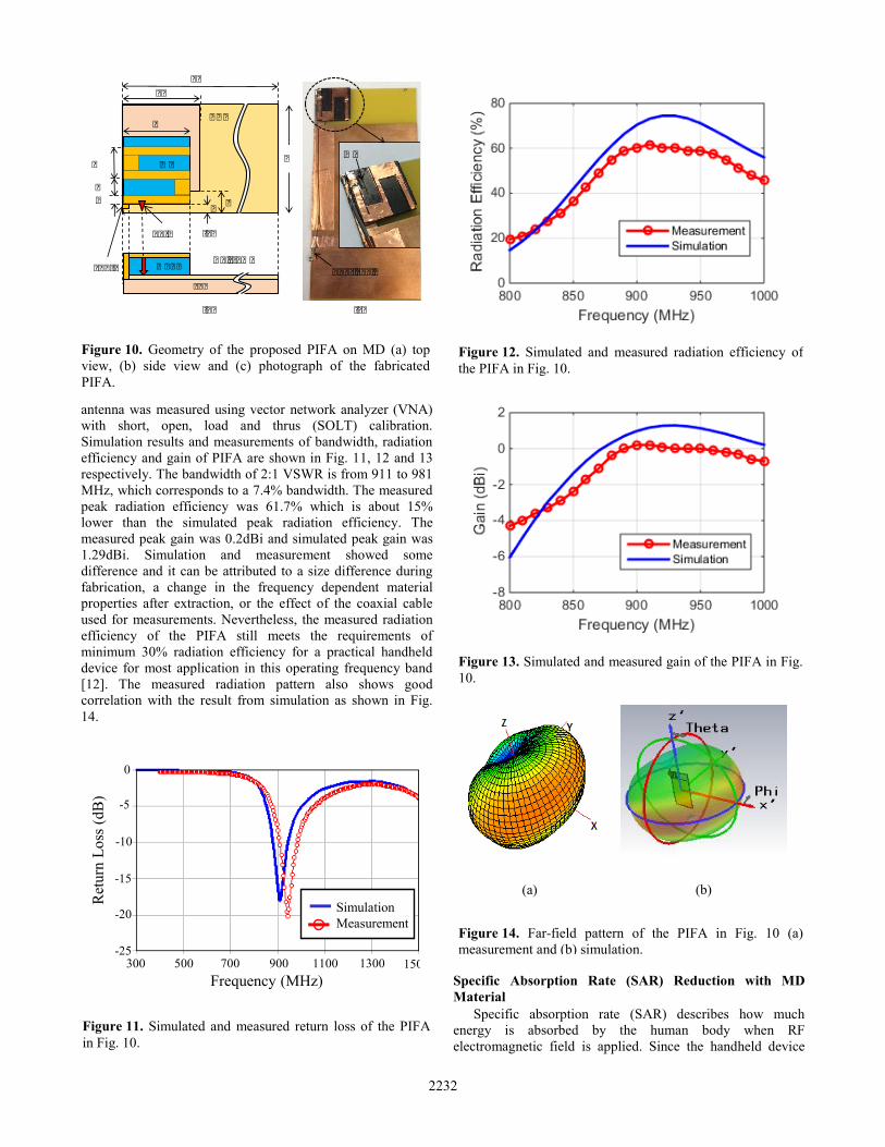
antenna was measured using vector network analyzer (VNA)
with short, open, load and thrus (SOLT) calibration.
Simulation results and measurements of bandwidth, radiation
efficiency and gain of PIFA are shown in Fig. 11, 12 and 13
respectively. The bandwidth of 2:1 VSWR is from 911 to 981
MHz, which corresponds to a 7.4% bandwidth. The measured
peak radiation efficiency was 61.7% which is about 15%
lower than the simulated peak radiation efficiency. The
measured peak gain was 0.2dBi and simulated peak gain was
1.29dBi. Simulation and measurement showed some
difference and it can be attributed to a size difference during
fabrication, a change in the frequency dependent material
properties after extraction, or the effect of the coaxial cable
used for measurements. Nevertheless, the measured radiation
efficiency of the PIFA still meets the requirements of
minimum 30% radiation efficiency for a practical handheld
device for most application in this operating frequency band
[12]. The measured radiation pattern also shows good
correlation with the result from simulation as shown in Fig.
14.
Specific Absorption Rate (SAR) Reduction with MD
Material
Specific absorption rate (SAR) describes how much
energy is absorbed by the human body when RF
electromagnetic field is applied. Since the handheld device
Figure 10. Geometry of the proposed PIFA on MD (a) top
view, (b) side view and (c) photograph of the fabricated
PIFA.
(b)
(a)
FR4
MDNC
Port
Short
GND
120
Units=mm
60
2
10
6
20
6
22
2
MDMD
Coax cable
(c)
Figure 11. Simulated and measured return loss of the PIFA
in Fig. 10.
0
Frequency (MHz)
Ret
urn
Lo
ss (
dB
)
Simulation
Measurement
300 500 700 900 1100 1300 1500
-5
-10
-15
-20
-25
Figure 12. Simulated and measured radiation efficiency of
the PIFA in Fig. 10.
Figure 13. Simulated and measured gain of the PIFA in Fig.
10.
Figure 14. Far-field pattern of the PIFA in Fig. 10 (a)
measurement and (b) simulation.
(a) (b)
2232
works very close to the human body, there is a strict
regulation for SAR. In this paper, the effect of loss
characteristics of the MD material to decrease SAR is studied
by comparing the peak SAR of PIFA on MD material
substrate, PIFAMD, and PIFA on other substrate materials. For
the same size antenna, PIFAHD, working at 900MHz was
designed with a high dielectric constant material. The relative
permittivity of the high dielectric constant material was 15.1
and the electric loss tangent was 0.002. Another antenna on
FR4 PCB, PIFAFR4, was designed and the size was optimized
to make the antenna resonate at 900MHz. The size of the
PIFAMD is about 38% smaller than the size of the PIFAFR4.
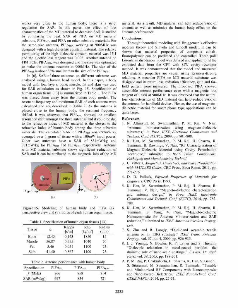
In [6], SAR of three antennas on different substrate was
analyzed using a human head model. In this paper, a body
model with four layers, bone, muscle, fat and skin was used
for SAR calculation as shown in Fig. 15. Specification of
human organ tissue [13] is summarized in Table 1. The PIFA
was placed 5mm away from the human body model. The
resonant frequency and maximum SAR of each antenna were
calculated and are described in Table 2. As the antenna is
placed close to the human body, the resonant frequency
shifted. It was observed that PIFAMD showed the smallest
resonance shift amongst the three antennas and it could be due
to the refractive index of MD material is the closest to the
refractive index of human body among the three substrate
materials. The calculated SAR of PIFAMD was 697mW/kg
averaged over 1 gram of tissue with a 100mW input power.
Other two antennas have a SAR of 834mW/kg and
721mW/kg for PIFAHD and PIFAFR4 respectively. Antenna
with MD material substrate shows significant reduction of
SAR and it can be attributed to the magnetic loss of the MD
material. As a result, MD material can help reduce SAR of
antenna as well as minimize the human body effect on the
antenna performance.
Conclusions
Through theoretical modeling with Bruggeman’s effective
medium theory and Sihvola and Lindell model, it can be
shown that material properties of composite cobalt-
fluoropolymer can be predicted and controlled. Three pole
Lorentzian dispersion model was derived and applied to fit the
extracted data from the CPT with SIW cavity resonator
method. It was demonstrated that the model and measured
MD material properties are causal using Kramers-Kronig
relations. A meander PIFA on MD material substrate was
designed and its return loss, radiation efficiency, gain and far-
field pattern were measured. The proposed PIFA showed
acceptable antenna performance even with a magnetic loss
tangent of 0.068 at 900MHz. It was observed that the natural
loss characteristics of MD material can help reduce SAR of
the antenna for handheld devices. Hence, the use of magneto-
dielectric material for smart phone type applications can be
quite large.
References
1. N. Altunyurt, M. Swaminathan, P. M. Raj, V. Nair,
“Antenna miniaturization using magneto-dielectric
substrates,” in Proc. IEEE Electronic Components and
Technol. Conf. (ECTC), 2009, pp. 801-808.
2. K. Han, M. Swaminathan, P. M. Raj, H. Sharma, R.
Tummala, B. Rawlings, V. Nair, “RF Characterization of
Magneto-Dielectric Material using Cavity Perturbation
Technique,” submitted to IEEE Trans. Components,
Packaging and Manufacturing Technol.
3. C. Vittoria, Magnetics, Dielectrics, and Wave Propagation
with MATLAB® Codes, CRC Press, Boca Raton, 2011, pp.
271-276.
4. D. D. Pollock, Physical Properties of Materials for
Engineers, CRC Press, 1993.
5. K. Han, M. Swaminathan, P. M. Raj, H. Sharma, R.
Tummala, V. Nair, “Magneto-dielectric characterization
and antenna design,” in Proc. IEEE Electronic
Components and Technol. Conf. (ECTC), 2014, pp. 782-
788.
6. K. Han, M. Swaminathan, P. M. Raj, H. Sharma, R.
Tummala, S. Yang, V. Nair, “Magneto-dielectric
Nanocomposite for Antenna Miniaturization and SAR
reduction,” submitted to IEEE Antennas Wireless Propag.
Lett.
7. S. Zhu and R. Langly, “Dual-band wearable textile
antenna on an EBG substrate,” IEEE Trans. Antennas
Propag., vol. 57, no. 4, 2009, pp. 926-935.
8. I. J. Youngs, N. Bowler, K. P. Lymer and S. Hussain,
“Dielectric relaxation in metal-coated particles: the
dramatic role of nano-scale coatings,” J. Phys. D: Appl.
Phys., vol. 38, 2005, pp. 188-201.
9. P. M. Raj, P. Chakrabortu, H. Sharma, K. Han, S. Gandhi,
S. Sitaraman, M. Swaminathan, R. Tummala, “Tunable
and Miniaturized RF Components with Nanocomposite
and Nanolayered Dielectrics,” IEEE Nanotechnol. Conf.
(IEEE NANO), 2014, pp. 27-31.
Figure 15. Modeling of human body and PIFA (a)
perspective view and (b) radius of each human organ tissue.
Table 1. Specification of human organ tissues [13]
Tissue εr Kappa
[s/m]
Rho
[kg/m3]
Radius
(mm)
Bone 12.45 0.143 1850 15
Muscle 56.87 0.995 1040 70
Fat 5.46 0.051 1100 73
Skin 41.40 0.867 1100 75
Table 2. Antenna performance with human body
Specification PIFAMD PIFAHD PIFAFR4
fr (MHz) 866 858 814
SAR (mW/kg) 697 834 721
x
y z z
x
y
r1
r2
r3
r4
bone
musclefat
skin
PIFA
(a) (b)
2233

10. K. N. Rozanov, Z. W. Li, L. F. Chen, M. Y. Koledintseva,
“Microwave permeability of Co2Z composites,” J of Appl.
Phys., vol. 97, 2005, pp. 013905.
11. A. E. Engin, “Extraction of Dielectric Constant and Loss
Tangent Using New Rapid Plane Solver and Analytical
Debye Modeling for Printed Circuit Boards,” IEEE Trans.
Microw. Theory Tech., vol. 58, 2010, pp. 211-219.
12. Y. L. Ban, J. H. Chen, S. Yang, J. L. W. Li, Y. J. Wu,
“Low-profile printed octa-band LTE/WWAN mobile
phone antenna using embedded parallel resonant
structure,” IEEE Trans. Antenna Propag., vol. 61, no. 7,
2013, pp. 3889-3894.
13. K. R. Holmes, “Thermal Conductivity Data for Specific
Tissues and Organs for Humans and Other Mammalian
Species,” Thermal Properties 2009.
2234