synfix-lr system. instruments and implants for stand-alone
TRANSCRIPT
Instruments and implants approved by the AO Foundation
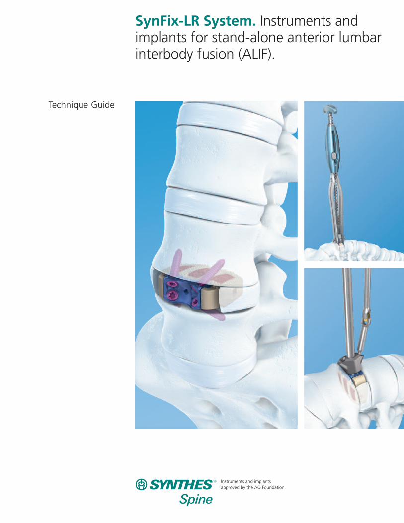
SynFix-LR System. Instruments andimplants for stand-alone anterior lumbarinterbody fusion (ALIF).
Technique Guide

Introduction
Surgical Technique
Product Information
Table of Contents
SynFix-LR System 2
AO Principles 4
Indications and Contraindications 5
Preoperative Planning 6
Preparation 7
Discectomy and Endplate Preparation 8
Trial for Implant Size 9
Insert ImplantOption A: Using SQUID 12Option B: Using Implant Holder 14
Insert Screws Using Mini-Open Instruments 16Mount Aiming Device 16Open Cortex 17Insert Screws 18Remove Instruments 21Verify Placement 22
Insert Screws Using Standard Instruments 23Mount Aiming Device 23Open Cortex 24Insert Screws 25Remove Instruments 28Verify Placement 29Implant Removal Procedure 30
Implants 31
Instruments 33
Set Lists 39
Image intensifier control
Synthes

ImplantsThe SynFix-LR implant is a stand-alone ALIF device that incorporates the benefits of an anterior plate and a radiolucentinterbody spacer. The design creates a zero-profile constructand includes four locking screws that provide anterior fixationand stability.
Stand-alone ALIF– Biomechanically equivalent to a spacer with pedicle screws1
– PEEK spacer provides modulus of elasticity similar to cortical bone
– Titanium plate with locking screws provides stable fixation
Zero-profile construct– Spacer and plate fit completely within the disc space
Anatomic shape – The SynFix-LR is convex to match the anatomy of the
disc space
– Two footprints and two lordotic angles are offered to accommodate individual patients
Screw and plate fixation– One-step conical locking mechanism ensures screws securely
lock to plate and eliminates need for blocking plate
– Locking screws provide stability and load transfer near thecortex of the vertebral body
– Four locking screws diverge to form a fixed-angle constructthat creates a wedge of bone (highlighted in yellow) for fixation
– Self-tapping cortical threads allow largest possible core diameter for maximum fixation
2 Synthes SynFix-LR System Technique Guide
SynFix-LR System
Titanium plate Material: Titanium alloy (Ti-6Al-7Nb)
PEEK spacerMaterial: PEEK (polyetheretherketone)
1. C.M. Cain, P. Schleicher, R. Gerlach, R. Pflugmacher, F. Scholz M, F. Kandziora “A New Stand-Alone Anterior Lumbar Interbody Fusion Device:Biomechanical Comparison with Established Fixation Techniques.” Spine. 2005 Dec 1; 30 (23): 2631-6.
Titanium screwMaterial: Titanium alloy (Ti-6Al-7Nb)
Double-lead locking threadsmate with threaded portion of plate

Simple instrumentationOnce disc preparation and implant trialing are complete, onlyfour simple instruments are needed to insert the SynFix-LR.
Fixed-handle aiming deviceFor precise positioning of the locking screws.
Low-profile awlPenetrates the cortical bone for screw insertion.
Low-profile driverProvides precise insertion of locking screws.
Synthes 3
SynFix Quick Inserter/Distractor (SQUID)Inserts and distracts in one simple step, without impaction.

AO Principles
In 1958, the AO formulated four basic principles, which havebecome the guidelines for internal fixation.2 They are:
– Anatomic reduction
– Stable internal fixation
– Preservation of blood supply
– Early, active mobilization
The fundamental aims of fracture treatment in the limbs andfusion of the spine are the same. A specific goal in the spineis returning as much function as possible to the injured neural elements.3
AO Principles as Applied to the Spine4
Anatomic alignmentRestoration of normal spinal alignment to improve the biomechanics of the spine.
Stable internal fixationStabilization of the spinal segment to promote bony fusion.
Preservation of blood supplyCreation of an optimal environment for fusion.
Early, active mobilizationMinimization of damage to the spinal vasculature, dura, andneural elements, which may contribute to pain reduction andimproved function for the patient.
2. M.E. Müller, M. Allgöwer, R. Schneider, and H. Willenegger Manual of InternalFixation, 3rd Edition. Berlin: Springer-Verlag. 1991.
3. Ibid.4. M. Aebi, J.S. Thalgott, J.K. Webb. AO ASIF Principles in Spine Surgery. Berlin:
Springer-Verlag. 1998.
4 Synthes SynFix-LR System Technique Guide

IndicationsThe Synthes SynFix-LR is a stand-alone anterior interbody fusion device indicated for use in patients with degenerativedisc disease (DDD) at one or two contiguous levels from L2 to S1. These DDD patients may also have up to Grade Ispondylolisthesis at the involved level(s). The interior of the spacer component of the SynFix-LR can be packed with autograft.
DDD is defined as back pain of discogenic origin with degeneration of the disc confirmed by history and radiographic studies. These patients should be skeletally mature and have had six months of nonoperative treatment.
ContraindicationsUse of the Synthes SynFix-LR is contraindicated when:– There is active systemic infection, infection localized to
the site of the proposed implantation, or when the patient
has demonstrated allergy or foreign body sensitivity to
any of the implant materials (PEEK, titanium, aluminum
and/or niobium).
– Severe osteoporosis may prevent adequate fixation and thus preclude the use of this or any other orthopaedic implant.
– Where patient anatomy or pathology prevents insertion of all four locking head screws.
Synthes 5
Indications and Contraindications

Preoperative Planning
Optional technique
Instruments
X000045* SynFix-LR Preoperative Planner, 26 x 32 mm, 8°
X000046* SynFix-LR Preoperative Planner, 26 x 32 mm, 12°
X000047* SynFix-LR Preoperative Planner, 30 x 38 mm, 8°
X000048* SynFix-LR Preoperative Planner, 30 x 38 mm, 8°
Determine the approximate implant size by comparing theSynFix-LR preoperative planner with a lateral radiograph ofthe patient’s adjacent intervertebral discs.
Notes:The height indicated on the template is approximately 1 mmlower than that of the actual spacer to account for penetra-tion of the teeth into the vertebral endplate.
It is recommended to select the maximum implant size, tooptimize the stability of the segment through tension in thelongitudinal ligaments.
6 Synthes SynFix-LR System Technique Guide
*Also available

Preparation
The surgical approach depends on the level to be treated;however, direct anterior access is required for the insertion of the locking screws.
Synthes 7
Exposure
The locking screws of the SynFix-LR system must be insertedfrom a direct anterior approach. Expose the segment to producesufficient space on either side of the vertebral midline, equalto half the width of the implant. This allows insertion of the implant, without interference from adjacent soft tissuestructures. (Two implant widths are available, 32 mm and 38 mm.)
Note:When the spacer has been inserted, visualization of the entire anterior plate is necessary for insertion of thelocking screws. Give proper consideration to the exposure so instrumentation can be used as depicted on the followingpages.
Anterior access and approach
Locate the correct operative disc level and incision locationby taking a lateral flouroscopic view while holding a straightmetal instrument at the side of the patient. This ensures thatthe incision and exposure will allow direct visualization intothe disc space.
Expose the operative disc level through a standard retroperi-toneal approach.
A mini-open retroperitoneal approach can be used with theSynFix mini-open instruments.

8 Synthes Spine SynFix-LR System Technique Guide
Discectomy and Endplate Preparation
1Discectomy and endplate preparation
Optional instrument
PDL114* Vertebral Body Spreader, angled
Create an annulotomy centered on the midline and wideenough to accommodate the SynFix-LR implant. A trial spacermay be used as a template to indicate the width of the annularwindow required.
Perform a thorough discectomy, ensuring the posterolateralcorners are freed of disc material.
Remove the cartilaginous endplates to bleeding bone, takingcare to not compromise the integrity of the bony endplates.If additional disc space distraction or remobilization is necessary,the spreader is available in the ProDisc-L Instrument Set.
Note: Excessive removal of subchondral bone may weakenthe vertebral endplate. If the entire endplate is removed,subsidence and a loss of segmental stability may result.
For a safe placement, verify spreader position with the helpof an intraoperative lateral x-ray.
*Also available

Trial for Implant Size
2 Trial for implant size
Instruments
03.802.000– SynFix-LR Trial Implants 03.802.019
389.151 Handle, for Trial Spacers
Optional instrument
397.113 Distractor, for SynFix-LR
PDL102 Slotted Mallet
Select the trial implant with the appropriate footprint andlordotic angle (see page 33). Firmly attach it to the trialspacer handle.
A distractor may be used to assist with guiding the trial spacerinto the disc space. To ensure that the implant is insertedsymmetrically into the disc space, the central line on the distractor blades should be aligned with the anterior midlineof the vertebral bodies.
Controlled, light hammering on the trial spacer handle maybe required to advance the trial spacer into the disc space.
Important: After impacting the trial spacer handle, it maybe necessary to retighten the handle.
Synthes 9

Trial for Implant Size
10 Synthes SynFix-LR System Technique Guide
2. Trial for implant size continued
If a tight fit is not achieved, repeat the process usingincrementally larger trial spacers. Conversely, if the trialspacer cannot be inserted, repeat using incrementally smallertrial spacers.
With the segment fully distracted, the trial spacer must fitfirmly in the disc space.
When rocking the trial spacer handle in a cranial to caudaldirection, no toggling of the trial spacer should be evident.
Note: Do not move the trial spacer handle laterally duringremoval. It is recommended that the slotted mallet be usedto remove the handle if necessary.
X-ray may be used to check the position of the trial implant,restoration of disc and foraminal height, and overall alignmentbefore selecting the final SynFix-LR implant size.
Synthes 11
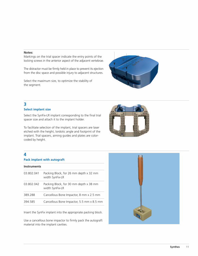
Notes: Markings on the trial spacer indicate the entry points of thelocking screws in the anterior aspect of the adjacent vertebrae.
The distractor must be firmly held in place to prevent its ejectionfrom the disc space and possible injury to adjacent structures.
Select the maximum size, to optimize the stability of the segment.
3Select implant size
Select the SynFix-LR implant corresponding to the final trialspacer size and attach it to the implant holder.
To facilitate selection of the implant, trial spacers are laseretched with the height, lordotic angle and footprint of theimplant. Trial spacers, aiming guides and plates are color-coded by height.
4Pack implant with autograft
Instruments
03.802.041 Packing Block, for 26 mm depth x 32 mm width SynFix-LR
03.802.042 Packing Block, for 30 mm depth x 38 mm width SynFix-LR
389.288 Cancellous Bone Impactor, 8 mm x 2.5 mm
394.585 Cancellous Bone Impactor, 5.5 mm x 8.5 mm
Insert the SynFix implant into the appropriate packing block.
Use a cancellous bone impactor to firmly pack the autograftmaterial into the implant cavities.

12 Synthes SynFix-LR System Technique Guide
Insert Implant
Engage/releasebutton
Main thread
5Insert implantOption A: Using SQUID
Instrument
03.802.121 SynFix-LR Synthes Quick Inserter/Distractor (SQUID)
Release the main thread by pushing the RELEASE button on the grip and slide the pusher fully back.
Place the instrument flat on the table to load the implant.
Place the implant onto the bottom spring ramp. Holding bothsides of the implant, engage the grooves with the springramp guides and gently slide the implant forward until theimplant is held without sliding back.
Slide the pusher up to the implant and engage the mainthread by pressing the ENGAGE button.
The implant is now held securely and is ready for insertion.
Note: The tips of the inserter will be inserted into the discspace up to the depth stops on the spring ramps; to allowfull insertion, the tips must not be spread apart.
Bottom spring rampDepth stops
Ejector
Pusher
Synthes 13
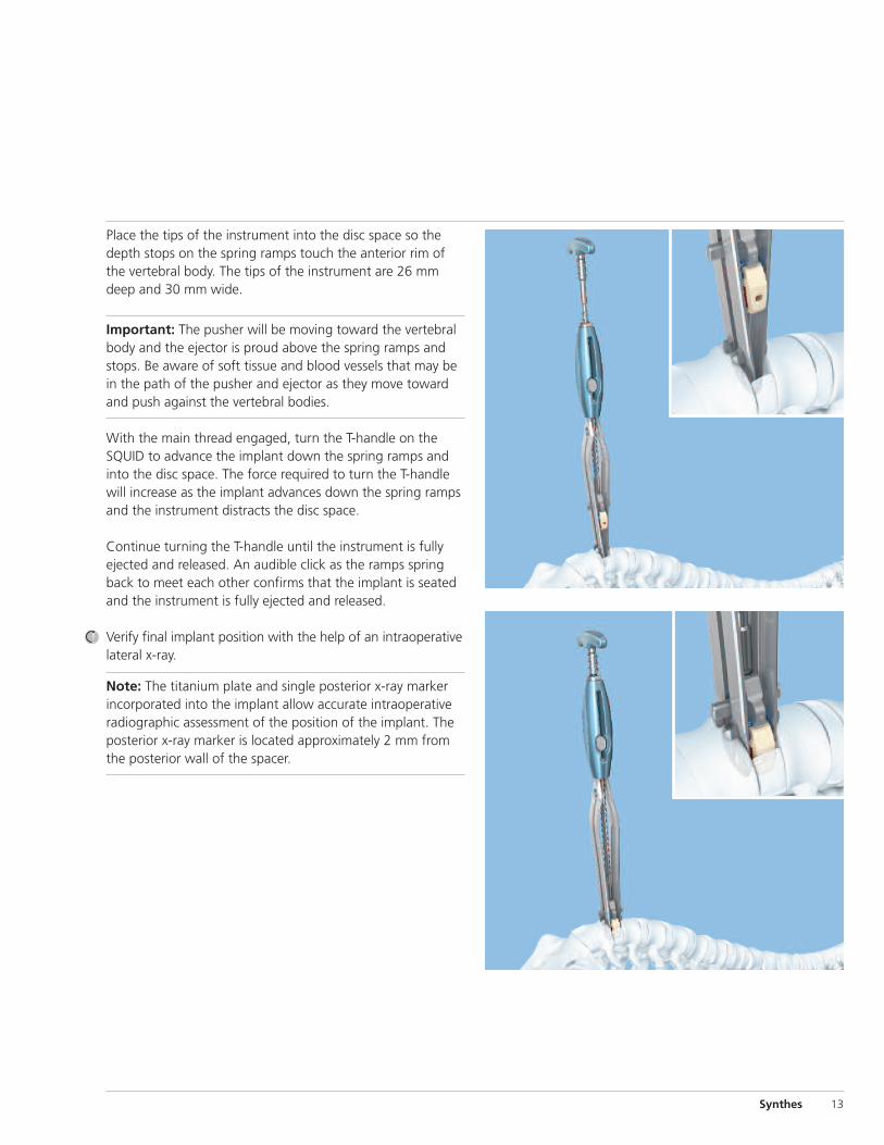
Place the tips of the instrument into the disc space so thedepth stops on the spring ramps touch the anterior rim ofthe vertebral body. The tips of the instrument are 26 mmdeep and 30 mm wide.
Important: The pusher will be moving toward the vertebralbody and the ejector is proud above the spring ramps andstops. Be aware of soft tissue and blood vessels that may bein the path of the pusher and ejector as they move towardand push against the vertebral bodies.
With the main thread engaged, turn the T-handle on theSQUID to advance the implant down the spring ramps andinto the disc space. The force required to turn the T-handlewill increase as the implant advances down the spring rampsand the instrument distracts the disc space.
Continue turning the T-handle until the instrument is fullyejected and released. An audible click as the ramps springback to meet each other confirms that the implant is seatedand the instrument is fully ejected and released.
Verify final implant position with the help of an intraoperativelateral x-ray.
Note: The titanium plate and single posterior x-ray markerincorporated into the implant allow accurate intraoperativeradiographic assessment of the position of the implant. Theposterior x-ray marker is located approximately 2 mm fromthe posterior wall of the spacer.

14 Synthes SynFix-LR System Technique Guide
Insert Implant
5. Insert implant continued
Option B: Using implant holder
Instrument
03.802.039 Implant Holder, for SynFix-LR
Optional instrument
397.113 Distractor, for SynFix-LR
Attach the implant holder to the SynFix-LR implant. The implantholder must be attached firmly to the plate to avoid damageto the implant holder or the plate.
Important: Do not cross thread the implant holder into theimplant. To prevent cross threading, ensure that the implantholder is perpendicular to the implant during engagement.
A distractor can be used to assist with guiding the implantinto the disc space. To ensure that the implant is insertedsymmetrically into the disc space, the central line on the distractor blades should be aligned with the anterior midlineof the vertebral bodies.
Slide the implant between the distractor blades and into thedisc space.
Hold the distractor firmly in place during implant insertion.
Verify final implant position with the help of an intraoperativelateral x-ray.
Notes: The titanium plate and single posterior x-ray markerincorporated into the implant allow accurate intraoperativeradiographic assessment of the position of the implant. Theposterior x-ray marker is located approximately 2 mm fromthe posterior wall of the spacer.
If it is necessary to remove the implant once it is positioned,see page 30 for implant removal procedure.

Synthes 15
Remove instrumentsWhen the implant is correctly positioned, if an optional distractor was used, loosen the locking nut on the distractorhandle and release the distraction.
Gently remove the distractor while the implant holder maintainsthe implant position.
After the distractor is removed, ensure a secure fit by lightlyhammering on the implant holder.
Remove the implant holder by rotating the handle counter-clockwise.
The implant should now be in its optimal position.
Depending on the size of the vertebrae, the anterior edge ofthe implant will usually be flush to three-millimeters-recessedrelative to the anterior aspect of the adjacent vertebrae.
Note: All instruments must be removed carefully to avoidpossible injury to adjacent structures.
Optional instrument
03.802.400 Handheld Retractor, curved, for SynFix-LR
The curved retractor can be used for additional tissue protectionwith both the mini-open and standard instrument sets. Anchorthe retractor under the selected aiming device for optimaltissue retraction. For additional information about the aimingdevice, see pages 17 and 24.
Notes:Before using the retractor, it is recommended to insert onescrew to prevent implant migration.
The retractor is not designed to withstand excessive forces.

16 Synthes SynFix-LR System Technique Guide
Insert Screws Using Mini-Open Instruments
Screws can be inserted using either mini-open instruments orstandard instruments (see pages 24–30 for Steps 6b–14b).
6aMount aiming device
Instruments
03.802.200 SynFix Mini-Open Implant Coupling
Mini-Open Fixed-Handle Aiming Devices03.802.202 For 12 mm SynFix (light blue) 03.802.203 For 13.5 mm SynFix (gold)03.802.205 For 15 mm SynFix (blue)03.802.207 For 17 mm SynFix (purple)03.802.209 For 19 mm SynFix (green)
The aiming devices are color-coded to correspond with theimplant height.
The aiming device ensures appropriate alignment of thescrews and engagement of the locking heads into the plate.
Warning: Do not use the awl or screwdriver without the appropriate aiming device.
Choose the appropriate aiming device and insert the implantcoupling.
Insert the aiming device into exposure. The arrows locatedjust below the handle indicate caudal and cranial orientationof the aiming device.
Position the aiming device so the threaded pin (a) fits intothe central hole of the plate and the lateral positioning pin(b) aligns with the plate hole for the locking screw.
When the aiming device has been positioned, secure it bytightening the implant coupling knob on the top of thefixed-handle aiming device.
Note: The aiming device should fit snugly against the plate.Do not overtighten.
Implant coupling Fixed-handle aiming device
a
b

Synthes 17
7aOpen cortex
Instrument
03.802.230 Low-Profile U-joint Awl, for SynFix Mini-Open
Insert the awl into the aiming device. Prepare the vertebralbody for screw insertion by applying pressure on the handleof the awl with rotational motions.
Notes: It is not necessary to impact or completely rotate the awl to break the cortex. Rotational motions clockwise and counterclockwise are sufficient.
The guiding forceps can be used as an option to control the tip while inserting into the aiming device.
The awl penetration is approximately 10 mm, equivalent to the purchase length of a 15 mm screw.
Insert the first screw before preparing any other holes.

18 Synthes SynFix-LR System Technique Guide
Insert Screws Using Mini-Open Instruments
8aInsert first screw
Instruments
03.802.431 Tapered U-Joint Driver for SynFix Mini-Open
03.802.038 Screw Holding Instrument, for SynFix-LR (guiding forceps)
388.396 Handle, with quick coupling, small
Optional Instrument
03.802.030 Screwdriver Shaft, T15
Select the appropriate screw length. Screw length should beselected to penetrate completely through the cortical bone.For a two-level procedure, proper consideration should begiven to the length of screw in the common vertebral bodyto prevent screw interference. Use the guiding forceps tocontrol the screw while inserting into or removing from theaiming device.
Important: The small handle with quick coupling is requiredwhen using the SynFix mini-open driver or the T15 screwdrivershaft. You must not use any other handle with either ofthese shafts.
The mini-open instruments can accommodate up to a 25 mmlength screw. For a 30 mm screw, use the standard instruments(see pages 24–30 for Steps 6b–14b).
Insert the self-tapping screw through the aiming device andinto the pilot hole created by the awl.
Important: Four (4) screws should always be used for every SynFix-LR construct.
The four locking screws should be inserted sequentially. Awland screw insertion should be done through a SynFix-LR aiming device, to ensure the proper locking of the screw tothe plate.
Synthes 19
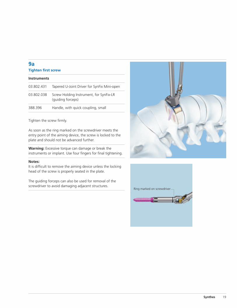
9aTighten first screw
Instruments
03.802.431 Tapered U-Joint Driver for SynFix Mini-open
03.802.038 Screw Holding Instrument, for SynFix-LR (guiding forceps)
388.396 Handle, with quick coupling, small
Tighten the screw firmly.
As soon as the ring marked on the screwdriver meets the entry point of the aiming device, the screw is locked to theplate and should not be advanced further.
Warning: Excessive torque can damage or break the instruments or implant. Use four fingers for final tightening.
Notes: It is difficult to remove the aiming device unless the lockinghead of the screw is properly seated in the plate.
The guiding forceps can also be used for removal of thescrewdriver to avoid damaging adjacent structures.
Ring marked on screwdriver

20 Synthes SynFix-LR System Technique Guide
Insert Screws Using Mini-Open Instruments
10aInsert second screw
Instruments
03.802.038 Screw Holding Instrument, for SynFix-LR (guiding forceps)
03.802.230 Low-Profile U-Joint Awl, for SynFix Mini-Open
03.802.431 Tapered U-Joint Driver for SynFix Mini-open
388.396 Handle, with quick coupling, small
Insert the second screw through the second opening in theaiming device, following Steps 7a through 9a.
Notes: It is difficult to remove the aiming device unless the lockinghead of the screw is properly seated in the plate.
The guiding forceps can also be used for removal of thescrewdriver to avoid damaging adjacent structures.
11aRotate aiming device
Loosen the aiming device by turning the implant couplingcounterclockwise four to five turns. The aiming device can berotated 180˚ without disengaging completely from the plate.
Arrows located just below the handle indicate caudal andcranial orientation of the aiming device.
Relock the aiming device by turning the implant couplingclockwise.
Notes:The fixed-handle aiming device can be rotated in either direction.
The aiming device should fit snugly against the plate, do not overtighten.

Synthes 21
12aInsert third and fourth screws
For insertion of the third and fourth screws, repeat Steps 7athrough 10a.
Note: Four (4) screws should always be used for every SynFix-LR construct.
13a Remove instruments
When the plate is secured, remove the aiming device byturning the implant coupling on top of the handle.
22 Synthes SynFix-LR System Technique Guide
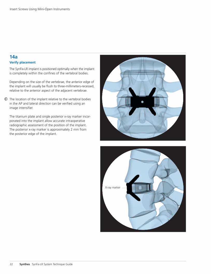
14a Verify placement
The SynFix-LR implant is positioned optimally when the implantis completely within the confines of the vertebral bodies.
Depending on the size of the vertebrae, the anterior edge ofthe implant will usually be flush to three-millimeters-recessed,relative to the anterior aspect of the adjacent vertebrae.
The location of the implant relative to the vertebral bodies in the AP and lateral direction can be verified using an image intensifier.
The titanium plate and single posterior x-ray marker incor-porated into the implant allow accurate intraoperative radiographic assessment of the position of the implant. The posterior x-ray marker is approximately 2 mm from the posterior edge of the implant.
X-ray marker
Insert Screws Using Mini-Open Instruments

Synthes 23
Insert Screws Using Standard Instruments
For inserting screws using mini-open instruments (Steps 6a–14a), see pages 17 – 23.
6bMount aiming device
Instruments
03.802.031 Aiming Device Holder, for SynFix-LR
Aiming Devices, for SynFix-LR03.802.020 12 mm (light blue) 03.802.032 13.5 mm (gold)03.802.036 15 mm (blue)03.802.033 17 mm (purple)03.802.034 19 mm (green)
The aiming devices are color-coded to correspond with theimplant height.
The aiming device ensures appropriate alignment of thescrews and engagement of the locking heads into the plate.
Warning: Do not use awl or screwdriver without appropriateaiming device.
Choose the appropriate aiming device and insert the implantcoupling.
Insert the aiming device into exposure.
Position the aiming device so the threaded pin (a) fits intothe central hole of the plate and the lateral positioning pin(b) aligns with the plate hole for the locking screw.
When the aiming device has been positioned, secure it bytightening the nut (c) on top of the aiming device holder.
Note: The aiming device should fit snugly against the plate,do not overtighten.
Aiming device holder
Aiming device
c
ba

24 Synthes SynFix-LR System Technique Guide
Insert Screws Using Standard Instruments
7b Open cortex
Instruments
03.802.035 Cortex Opener, for SynFix-LR (awl)
03.802.038 Screw Holding Instrument, for SynFix-LR (guiding forceps)
For better visualization of the operative site, the aiming deviceholder can be removed, leaving the aiming device attachedto the plate.
Insert the awl into the aiming device. Prepare the vertebralbody for screw insertion by applying pressure on the handleof the awl with rotational motions. Guiding forceps shouldbe used to ensure directional control of the awl tip.
Notes: Use the guiding forceps to control the tip of the awl and toavoid injury to the surrounding soft tissues or vessels.
The guiding forceps can also be used for removal of the awl,to avoid damaging adjacent structures.
It is not necessary to impact or completely rotate the awl tobreak the cortex. Rotational motions clockwise and counter-clockwise are sufficient.
The awl penetration is approximately 10 mm, equivalent to the purchase length of a 15 mm screw.
Insert the first screw before preparing any other holes.

Synthes 25
8b Insert first screw
Instruments
03.802.037 Screwdriver, for SynFix-LR
03.802.038 Screw Holding Instrument, for SynFix-LR (guiding forceps)
Optional Instruments
03.802.030 Screwdriver Shaft, T15
388.396 Handle, with quick coupling, small
Select the appropriate screw length. Screw length should beselected to penetrate completely through the cortical bone.For a two-level procedure, proper consideration should begiven to the length of screw in the common vertebral bodyto prevent screw interference.
Insert the self-tapping screws with the screwdriver and theguiding forceps, through the aiming device and into the pilothole created by the awl.
Important: The small handle with quick coupling is requiredwhen using the T15 screwdriver shaft. You must not use anyother handle with this shaft.
Four (4) screws should always be used for every SynFix-LRconstruct.
The four locking screws should be inserted sequentially. Awland screw insertion should be done through a SynFix-LR aimingdevice to ensure the proper locking of the screw to the plate.
Notes: The guiding forceps allow control of the screw during insertion,to avoid damage to the surrounding soft tissue or vessels.
The guiding forceps can also be used for removal of thescrewdriver to avoid damaging adjacent structures.

26 Synthes SynFix-LR System Technique Guide
Insert Screws Using Standard Instruments
9b Tighten the first screw
Instruments
03.802.037 Screwdriver, for SynFix-LR
03.802.038 Screw Holding Instrument, for SynFix-LR (guiding forceps)
Tighten the screw firmly.
As soon as the ring marked on the screwdriver meets the entry point of the aiming device, the screw is locked to theplate and should not be advanced further.
Warning: Excessive torque can damage or break the instruments or implant. Use four fingers for final tightening.
Notes: It is difficult to remove the aiming device unless the lockinghead of the screw is properly seated in the plate.
The guiding forceps can also be used for removal of thescrewdriver to avoid damaging adjacent structures.
Ring marked on screwdriver
Synthes 27
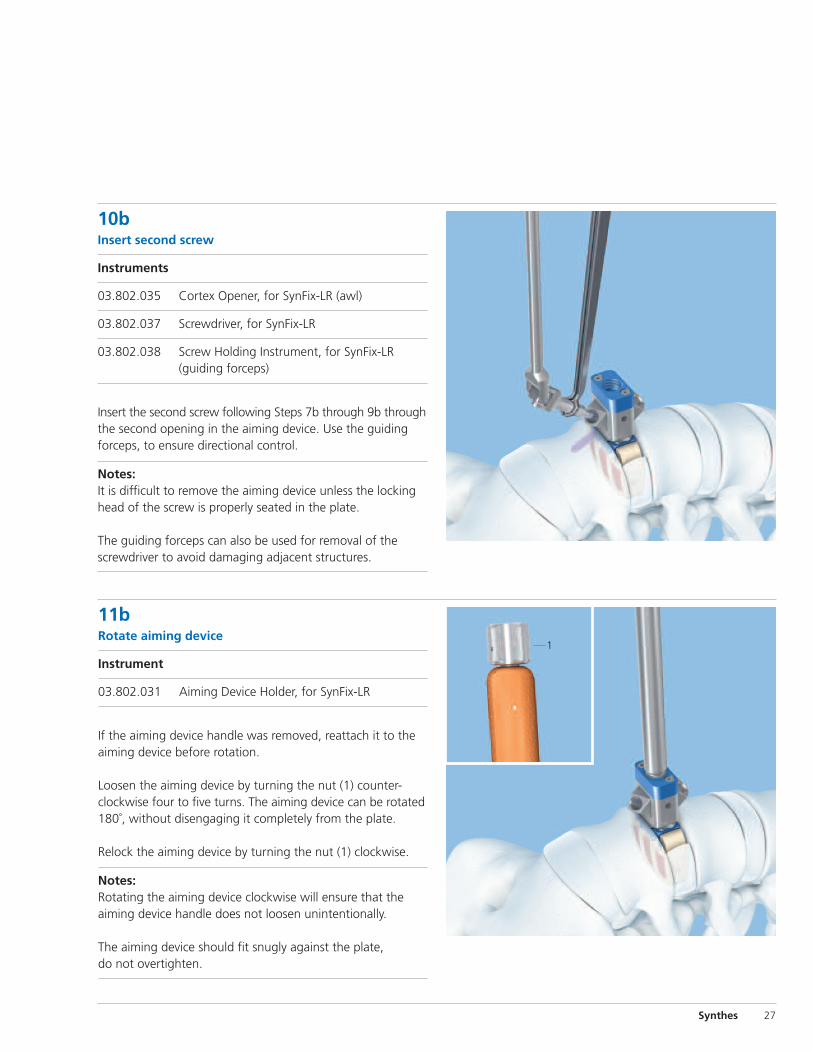
10b Insert second screw
Instruments
03.802.035 Cortex Opener, for SynFix-LR (awl)
03.802.037 Screwdriver, for SynFix-LR
03.802.038 Screw Holding Instrument, for SynFix-LR (guiding forceps)
Insert the second screw following Steps 7b through 9b throughthe second opening in the aiming device. Use the guidingforceps, to ensure directional control.
Notes: It is difficult to remove the aiming device unless the lockinghead of the screw is properly seated in the plate.
The guiding forceps can also be used for removal of thescrewdriver to avoid damaging adjacent structures.
11b Rotate aiming device
Instrument
03.802.031 Aiming Device Holder, for SynFix-LR
If the aiming device handle was removed, reattach it to theaiming device before rotation.
Loosen the aiming device by turning the nut (1) counter-clockwise four to five turns. The aiming device can be rotated180˚, without disengaging it completely from the plate.
Relock the aiming device by turning the nut (1) clockwise.
Notes:Rotating the aiming device clockwise will ensure that theaiming device handle does not loosen unintentionally.
The aiming device should fit snugly against the plate, do not overtighten.
1
28 Synthes SynFix-LR System Technique Guide
Insert Screws Using Standard Instruments
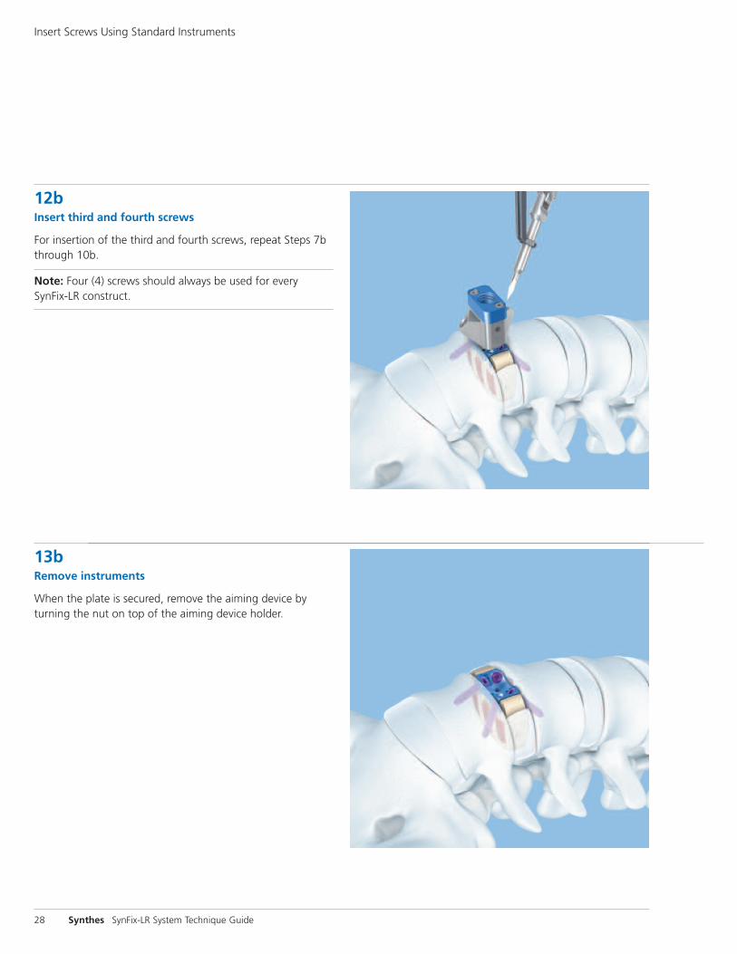
12b Insert third and fourth screws
For insertion of the third and fourth screws, repeat Steps 7bthrough 10b.
Note: Four (4) screws should always be used for every SynFix-LR construct.
13b Remove instruments
When the plate is secured, remove the aiming device byturning the nut on top of the aiming device holder.

Synthes 29
14b Verify placement
The SynFix-LR implant is positioned optimally when the implantis completely within the confines of the vertebral bodies.
Depending on the size of the vertebrae, the anterior edge ofthe implant will usually be flush to three-millimeters-recessed,relative to the anterior aspect of the adjacent vertebrae.
The location of the implant relative to the vertebral bodies in the AP and lateral direction can be verified using an image intensifier.
The titanium plate and single posterior x-ray marker incorporated into the implant allow accurate intraoperative radiographic assessment of the position of the implant. The posterior x-ray marker is approximately 2 mm from the posterior edge of the implant.
X-ray marker
30 Synthes SynFix-LR System Technique Guide
Implant Removal Procedure
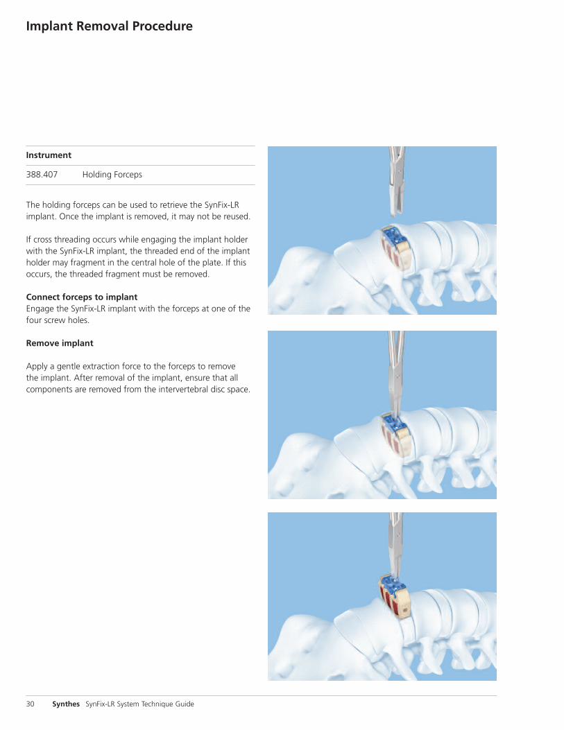
Instrument
388.407 Holding Forceps
The holding forceps can be used to retrieve the SynFix-LR implant. Once the implant is removed, it may not be reused.
If cross threading occurs while engaging the implant holderwith the SynFix-LR implant, the threaded end of the implantholder may fragment in the central hole of the plate. If thisoccurs, the threaded fragment must be removed.
Connect forceps to implantEngage the SynFix-LR implant with the forceps at one of thefour screw holes.
Remove implant
Apply a gentle extraction force to the forceps to remove the implant. After removal of the implant, ensure that allcomponents are removed from the intervertebral disc space.

Synthes 31
SynFix-LR Implants– Supplied sterile and preassembled (spacer with
anterior plate)
– Plate components are color-coded by height
– Cage component: PEEK (polyetheretherketone)
– Plate component: titanium alloy (Ti-6Al-7Nb)
Implants
angle
26 mm x 32 mm Lordotic angle Height (mm) Posterior Height (mm) Color
08.802.016S 8º 12 9 Light Blue
08.802.000S 8º 13.5 10.5 Gold
08.802.001S 8º 15 12 Blue
08.802.002S 8º 17 14 Purple
08.802.003S 8º 19 16 Green
08.802.017S 12º 12 7.5 Light Blue
08.802.004S 12º 13.5 9 Gold
08.802.005S 12º 15 10.5 Blue
08.802.006S 12º 17 12.5 Purple
08.802.007S 12º 19 14.5 Green
30 mm x 38 mm Lordotic angle Height (mm) Posterior Height (mm) Color
08.802.018S 8º 12 8.5 Light Blue
08.802.008S 8º 13.5 10 Gold
08.802.009S 8º 15 11.5 Blue
08.802.010S 8º 17 13.5 Purple
08.802.011S 8º 19 15.5 Green
08.802.019S 12º 12 7 Light Blue
08.802.012S 12º 13.5 8.5 Gold
08.802.013S 12º 15 10 Blue
08.802.014S 12º 17 12 Purple
08.802.015S 12º 19 14 Green
*Posterior height is measured from the top of the most posterior teeth. Total combined height of teeth is 1.8 mm.
height posterior height*
26 mm depth 30 mm depth
38 mm width
32 mm width
Implants shown actual size

32 Synthes SynFix-LR System Technique Guide
purchase**
length
4.0 mm Titanium Locking Screws– Self-tapping
– Titanium alloy (Ti-6Al-7Nb)
Length (mm) Bone Purchase (mm)04.802.200 15 1004.802.201 20 1504.802.202 25 2004.802.203 30 25
30º
**Bone purchase is approximately 5 mm less than length.
42º
4.0 mm Titanium Locking Screws, fine tip– Self-tapping
– Titanium alloy (Ti-6Al-7Nb)
– Designed to more easily penetrate dense sclerotic bone
Length (mm) Bone Purchase (mm)04.802.210 15 1004.802.211 20 1504.802.212 25 2004.802.213 30 25
purchase**
length
Implants

Synthes 33
Instruments
26 mm x 32 mm 30 mm x 38 mm Lordotic angle Height (mm) Color
03.802.016 03.802.018 8º 12 Light Blue
03.802.000 03.802.008 8º 13.5 Gold
03.802.001 03.802.009 8º 15 Blue
03.802.002 03.802.010 8º 17 Purple
03.802.003 03.802.011 8º 19 Green
03.802.017 03.802.019 12º 12 Light Blue
03.802.004 03.802.012 12º 13.5 Gold
03.802.005 03.802.013 12º 15 Blue
03.802.006 03.802.014 12º 17 Purple
03.802.007 03.802.015 12º 19 Green
SynFix-LR Trial Implants– Color-coded by height
– Color corresponds to the SynFix-LR implant plate component
26 mm depth 30 mm depth
38 mm width
32 mm width
Trial Implants shown actual size
Instruments
34 Synthes SynFix-LR System Technique Guide
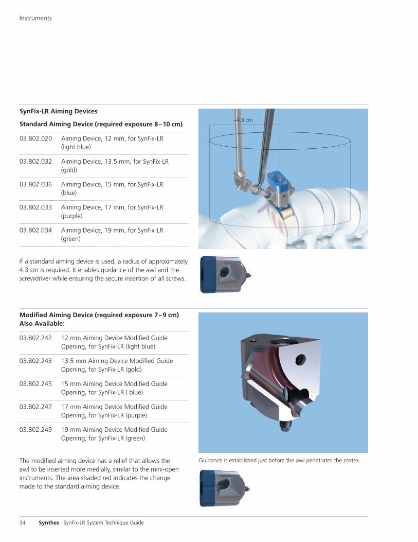
SynFix-LR Aiming Devices
Standard Aiming Device (required exposure 8–10 cm)
03.802.020 Aiming Device, 12 mm, for SynFix-LR (light blue)
03.802.032 Aiming Device, 13.5 mm, for SynFix-LR (gold)
03.802.036 Aiming Device, 15 mm, for SynFix-LR (blue)
03.802.033 Aiming Device, 17 mm, for SynFix-LR (purple)
03.802.034 Aiming Device, 19 mm, for SynFix-LR (green)
If a standard aiming device is used, a radius of approximately4.3 cm is required. It enables guidance of the awl and thescrewdriver while ensuring the secure insertion of all screws.
Modified Aiming Device (required exposure 7–9 cm)Also Available:
03.802.242 12 mm Aiming Device Modified Guide Opening, for SynFix-LR (light blue)
03.802.243 13.5 mm Aiming Device Modified Guide Opening, for SynFix-LR (gold)
03.802.245 15 mm Aiming Device Modified Guide Opening, for SynFix-LR ( blue)
03.802.247 17 mm Aiming Device Modified Guide Opening, for SynFix-LR (purple)
03.802.249 19 mm Aiming Device Modified Guide Opening, for SynFix-LR (green)
The modified aiming device has a relief that allows the awl to be inserted more medially, similar to the mini-open instruments. The area shaded red indicates the change made to the standard aiming device.
~4.3 cm
Guidance is established just before the awl penetrates the cortex.
Synthes 35
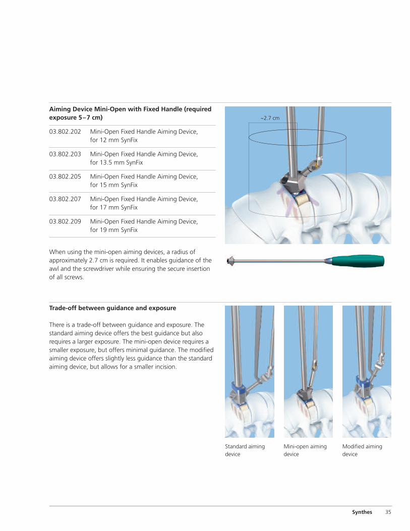
Trade-off between guidance and exposure
There is a trade-off between guidance and exposure. Thestandard aiming device offers the best guidance but also requires a larger exposure. The mini-open device requires asmaller exposure, but offers minimal guidance. The modifiedaiming device offers slightly less guidance than the standardaiming device, but allows for a smaller incision.
Aiming Device Mini-Open with Fixed Handle (requiredexposure 5–7 cm)
03.802.202 Mini-Open Fixed Handle Aiming Device, for 12 mm SynFix
03.802.203 Mini-Open Fixed Handle Aiming Device, for 13.5 mm SynFix
03.802.205 Mini-Open Fixed Handle Aiming Device, for 15 mm SynFix
03.802.207 Mini-Open Fixed Handle Aiming Device, for 17 mm SynFix
03.802.209 Mini-Open Fixed Handle Aiming Device, for 19 mm SynFix
When using the mini-open aiming devices, a radius ofapproximately 2.7 cm is required. It enables guidance of theawl and the screwdriver while ensuring the secure insertionof all screws.
Standard aiming device
Mini-open aiming device
Modified aiming device
~2.7 cm

36 Synthes SynFix-LR System Technique Guide
Instruments
03.802.039 Implant Holder, for SynFix-LRFor use with Distractor (397.113)
03.802.030 Screwdriver Shaft, T15
03.802.031 Aiming Device Holder, for SynFix-LR
03.802.035 Cortex Opener, for SynFix-LR
03.802.037 Screwdriver, for SynFix-LR
03.802.038 Screw Holding Instrument, for SynFix-LR

Synthes 37
03.802.041 Packing Block, for 26 mm depth x 32 mmwidth SynFix-LR
03.802.042 Packing Block, for 30 mm depth x 38 mmwidth SynFix-LR
03.802.121 SynFix-LR Synthes Quick Inserter /Distractor (SQUID)
03.802.200 SynFix Mini-Open Implant Coupling
03.802.230 Low Profile U-Joint Awl, for SynFix Mini-Open
03.802.431 Tapered U-Joint Driver, for SynFix Mini-Open

38 Synthes SynFix-LR System Technique Guide
388.396 Handle, with quick coupling, small
389.151 Handle, for Trial Spacers
389.288 Cancellous Bone Impactor, 8 mm x 2.5 mm394.585 Cancellous Bone Impactor, 5.5 mm x 8.5 mm
397.113 Distractor, for SynFix-LR
388.407 Holding Forceps
Instruments

SynFix-LR Standard Instrument Set (01.802.110)
Synthes 39
Graphic Case60.802.110 Graphic Case, for SynFix-LR Standard
Instruments
Instruments03.802.030 Screwdriver Shaft, T1503.802.031 Aiming Device Holder, for SynFix-LR
Aiming Devices, for SynFix-LR03.802.020 12 mm03.802.032 13.5 mm03.802.036 15 mm03.802.033 17 mm03.802.034 19 mm
03.802.035 Cortex Opener, for SynFix-LR03.802.037 Screwdriver, for SynFix-LR03.802.038 Screw Holding Instrument, for SynFix-LR03.802.039 Implant Holder, for SynFix-LR03.802.041 Packing Block, for 26 mm depth x 32 mm
width SynFix-LR03.802.042 Packing Block, for 30 mm depth x 38 mm
width SynFix-LR388.396 Handle, with quick coupling, small389.288 Cancellous Bone Impactor, 8 mm x 2.5 mm394.585 Cancellous Bone Impactor, 5.5 mm x 8.5 mm397.113 Distractor, for SynFix-LR
Also Available60.802.240 Module for SynFix-LR Aiming Devices
Aiming Devices, Modified Guide Opening, for SynFix-LR
03.802.242 12 mm03.802.243 13.5 mm 03.802.245 15 mm 03.802.247 17 mm 03.802.249 19 mm
Note: For additional information, please refer to package insert. For detailed cleaning and sterilization instructions, please refer tohttp://us.synthes.com/Medical+Community /Cleaning+and+Sterilization.htmor to the below listed inserts, which will be included in the shipping container:– Processing Synthes Reusable Medical Devices—Instruments, Instrument Trays
and Graphic Cases—DJ1305– Processing Non-sterile Synthes Implants—DJ1304

40 Synthes SynFix-LR System Technique Guide
SynFix-LR Mini-Open Instrument Set (01.802.120)
Graphic Case60.802.120 Graphic Case, for SynFix Mini-Open
Instruments
Instruments03.802.121 SynFix-LR Synthes Quick Inserter /Distractor
(SQUID)03.802.200 SynFix Mini-Open Implant Coupling, 2 ea.
Mini-Open Fixed Handle Aiming Devices, for SynFix
03.802.202 12 mm03.802.203 13.5 mm 03.802.205 15 mm 03.802.207 17 mm 03.802.209 19 mm
03.802.230 Low Profile U-Joint Awl, for SynFix Mini-Open 03.802.431 Tapered U-Joint Driver for SynFix Mini-Open388.396 Handle, with quick coupling, small388.407 Holding Forceps
Also Available PDL114 Vertebral Body Spreader, angled 03.802.400 Hand-Held Retractor Curved, for SynFix-LR
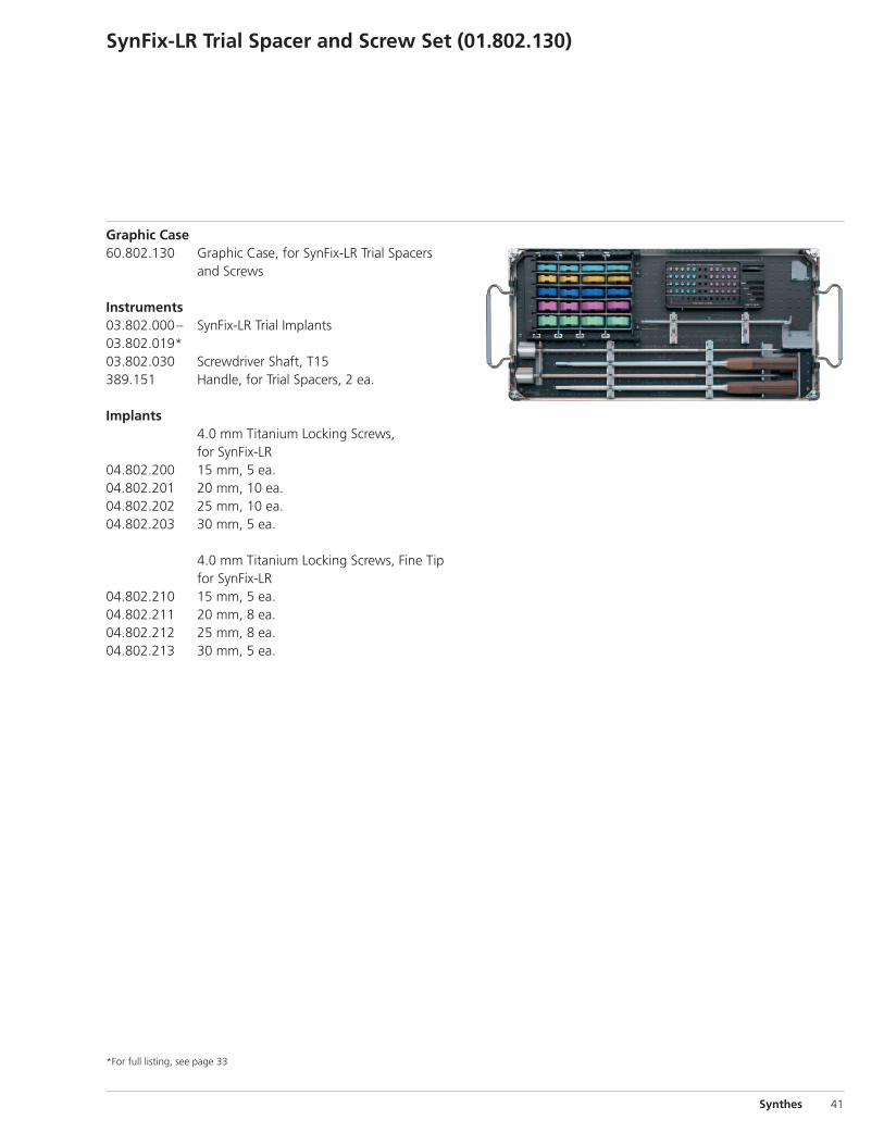
SynFix-LR Trial Spacer and Screw Set (01.802.130)
Synthes 41
Graphic Case60.802.130 Graphic Case, for SynFix-LR Trial Spacers
and Screws
Instruments03.802.000– SynFix-LR Trial Implants03.802.019*03.802.030 Screwdriver Shaft, T15389.151 Handle, for Trial Spacers, 2 ea.
Implants4.0 mm Titanium Locking Screws, for SynFix-LR
04.802.200 15 mm, 5 ea.04.802.201 20 mm, 10 ea. 04.802.202 25 mm, 10 ea. 04.802.203 30 mm, 5 ea.
4.0 mm Titanium Locking Screws, Fine Tip for SynFix-LR
04.802.210 15 mm, 5 ea.04.802.211 20 mm, 8 ea.04.802.212 25 mm, 8 ea.04.802.213 30 mm, 5 ea.
*For full listing, see page 33
42 Synthes SynFix-LR System Technique Guide
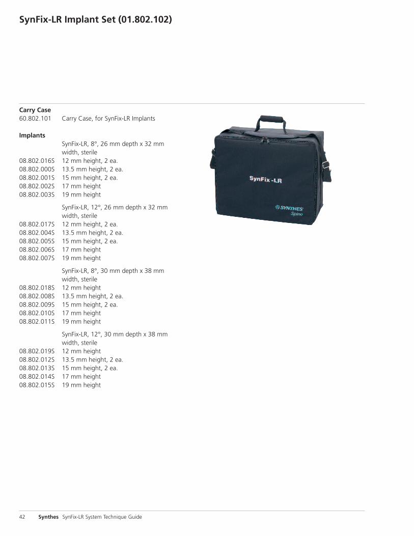
SynFix-LR Implant Set (01.802.102)
Carry Case60.802.101 Carry Case, for SynFix-LR Implants
ImplantsSynFix-LR, 8°, 26 mm depth x 32 mm width, sterile
08.802.016S 12 mm height, 2 ea.08.802.000S 13.5 mm height, 2 ea.08.802.001S 15 mm height, 2 ea.08.802.002S 17 mm height08.802.003S 19 mm height
SynFix-LR, 12°, 26 mm depth x 32 mm width, sterile
08.802.017S 12 mm height, 2 ea.08.802.004S 13.5 mm height, 2 ea.08.802.005S 15 mm height, 2 ea.08.802.006S 17 mm height08.802.007S 19 mm height
SynFix-LR, 8°, 30 mm depth x 38 mm width, sterile
08.802.018S 12 mm height08.802.008S 13.5 mm height, 2 ea.08.802.009S 15 mm height, 2 ea.08.802.010S 17 mm height08.802.011S 19 mm height
SynFix-LR, 12°, 30 mm depth x 38 mm width, sterile
08.802.019S 12 mm height08.802.012S 13.5 mm height, 2 ea.08.802.013S 15 mm height, 2 ea.08.802.014S 17 mm height08.802.015S 19 mm height

SynFix-LR System (01.802.100)
Consists of Sets:01.802.110 SynFix-LR Standard Instrument Set01.802.120 SynFix-LR Mini-Open Instrument Set01.802.130 SynFix-LR Trial Spacer and Screw Set01.802.102 SynFix-LR Implant Set
Synthes 43

Synthes Spine1302 Wrights Lane EastWest Chester, PA 19380Telephone: (610) 719-5000To order: (800) 523-0322Fax: (610) 251-9056
Synthes (Canada) Ltd.2566 Meadowpine BoulevardMississauga, Ontario L5N 6P9Telephone: (905) 567-0440To order: (800) 668-1119Fax: (905) 567-3185
© 2008 Synthes, Inc. or its affiliates. All rights reserved. SynFix and Synthes are trademarks of Synthes, Inc. or its affiliates. Printed in U.S.A. 8/10 J7022-H
www.synthes.com