surgical techniquesynthes.vo.llnwd.net/o16/llnwmb8/int mobile/synthes international...surgical...
TRANSCRIPT
Surgical Technique
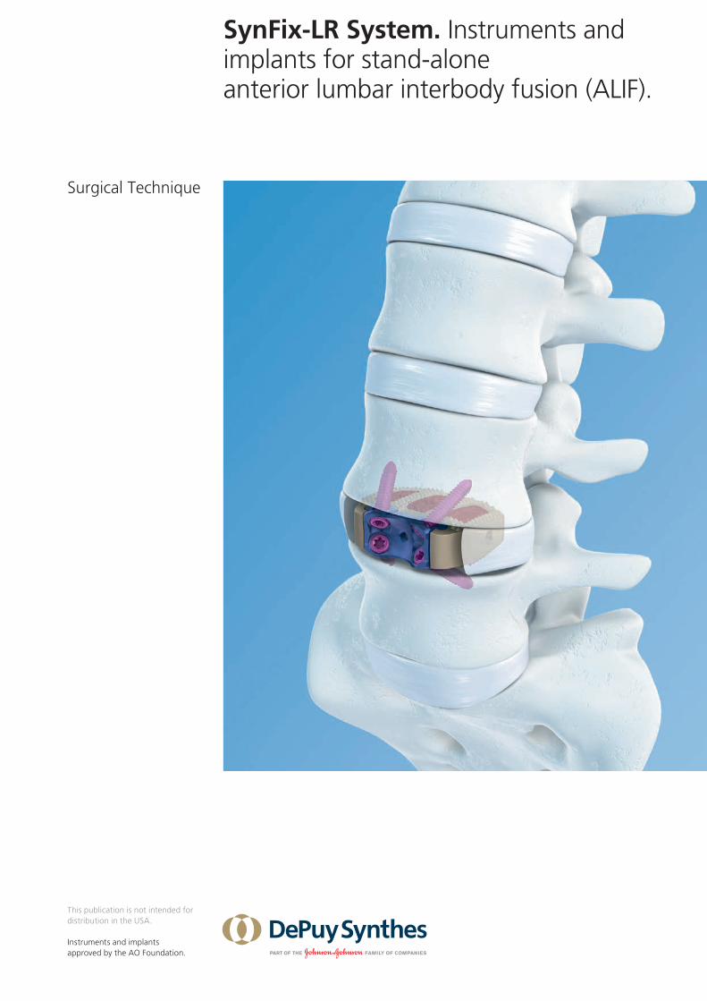
SynFix-LR System. Instruments and implants for stand-alone anterior lumbar interbody fusion (ALIF).
This publication is not intended for distribution in the USA.
Instruments and implants approved by the AO Foundation.

Image intensifier control
WarningThis description alone does not provide sufficient background for direct use of DePuy Synthes products. Instruction by a surgeon experienced in handling these products is highly recommended.
Processing, Reprocessing, Care and MaintenanceFor general guidelines, function control and dismantling of multi-part instruments, as well as processing guidelines for implants, please contact your local sales representative or refer to:http://emea.depuysynthes.com/hcp/reprocessing-care-maintenanceFor general information about reprocessing, care and maintenance of Synthes reusable devices, instrument trays and cases, as well as processing of Synthes non-sterile implants, please consult the Important Information leaflet (SE_023827) or refer to: http://emea.depuysynthes.com/hcp/reprocessing-care-maintenance

Surgical Technique SynFix-LR System DePuy Synthes 1
Introduction SynFix-LR System 2
AO Principles 6
Indications and Contraindications 7
Surgical Technique Preoperative Planning 8
Access and Exposure 9
Preparation 11
Selection and Packing of Implant 15
Implant Insertion Option A: SQUID 18 Option B: Implant Holder 21
Screw Insertion Option A: Standard Instruments 23 Option B: Mini-Open Instruments 31
Product Information Implant Removal 38
SynFix-LR Implants 40
SynFix-LR Screws 41
SynFix-LR Trial Implants 42
SynFix-LR Instruments 43
SynFix-LR Aiming Devices 46
Filling Material 48
Additional Recommended Sets 50
Disassembly Instruction 51
Assembly Instruction 52
Bibliography 53
Table of Contents
2 DePuy Synthes SynFix-LR System Surgical Technique
SynFix-LR System. Instruments and implants for stand-alone anterior lumbar interbody fusion (ALIF).
SynFix-LR Implants
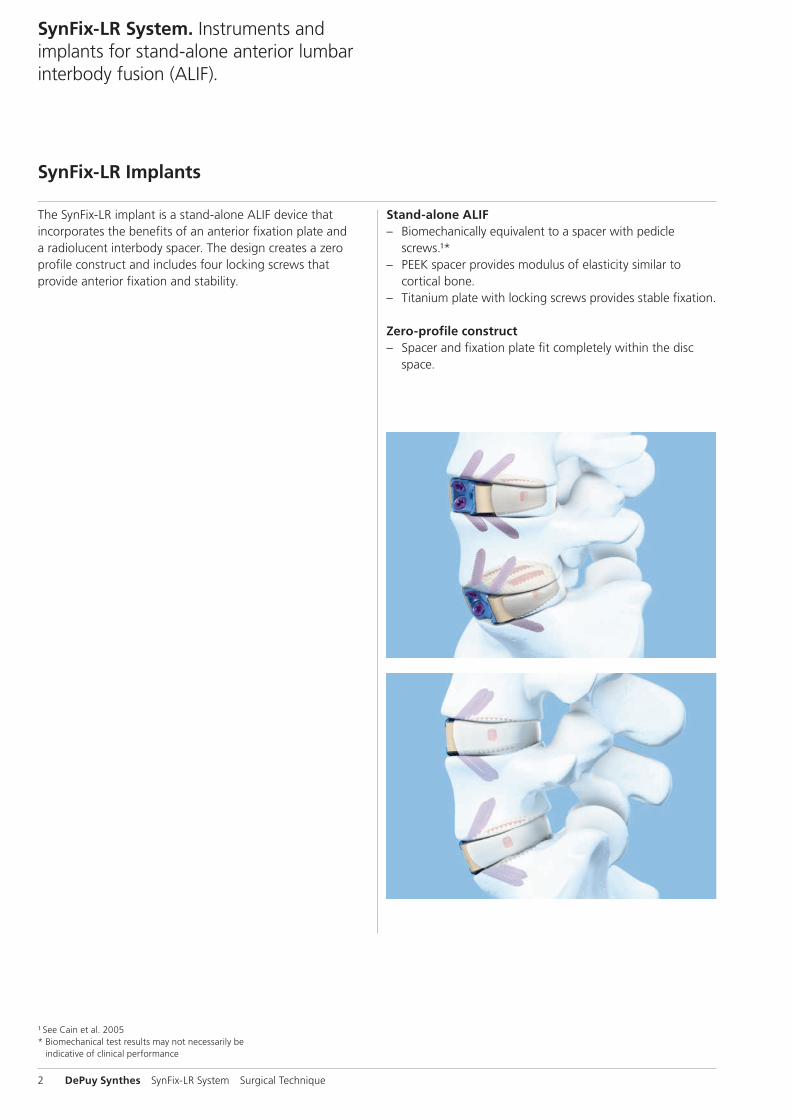
The SynFix-LR implant is a stand-alone ALIF device thatincorporates the benefits of an anterior fixation plate anda radiolucent interbody spacer. The design creates a zeroprofile construct and includes four locking screws thatprovide anterior fixation and stability.
Stand-alone ALIF – Biomechanically equivalent to a spacer with pedicle
screws.¹* – PEEK spacer provides modulus of elasticity similar to
cortical bone. – Titanium plate with locking screws provides stable fixation.
Zero-profile construct – Spacer and fixation plate fit completely within the disc
space.
¹ See Cain et al. 2005* Biomechanical test results may not necessarily be
indicative of clinical performance

Surgical Technique SynFix-LR System DePuy Synthes 3
Titanium plate material: Titanium alloy (TiAl6Nb7)
Double-lead locking threads mate with threaded portion of plate
Titanium screw material: Titanium alloy (TiAl6Nb7)
Screw and plate fixation – One-step conical locking mechanism ensures screws securely
lock to plate and eliminates the need for a blocking plate. – Locking screws provide stability and load transfer near the
cortex of the vertebral body. – Four locking screws diverge to form a fixed-angle construct
that creates a wedge of bone (highlighted in yellow) for fixation.
– Self-tapping cortical threads allow largest possible core diameter for maximum fixation.
Anatomic shape – The SynFix-LR is convex to match the anatomy of the
disc space. – Two footprints and two angles are offered to accommo-
date individual patient anatomy.
PEEK spacer material: PEEK (polyetheretherketone)

4 DePuy Synthes SynFix-LR System Surgical Technique
SynFix-LR System. Instruments and implants for stand-alone anterior lumbar interbody fusion (ALIF).
Instruments for insertion of the implant
Option A:
Quick inserter (SQUID)The SynFix SQUID inserts in one simple step, withoutimpaction.
Option B:
Implant holder and distractorFor the insertion of the implant while distraction is main-tained.

Surgical Technique SynFix-LR System DePuy Synthes 5
Instruments for insertion of the screws
Standard instruments option A:
Awl with cardan joint Penetrates the cortical rim for subsequent screw insertion.
Mini-open instruments option B:
Aiming device mini-open with fixed handleFor precise positioning of the locking screws.
TweezersFor guiding awl and screwdriver into the aiming device.
Awl for SynFix-LR mini-openPenetrates the cortical rim for subsequent screw insertion.
Aiming device holder with implant couplingFor insertion of the aiming device. Easily removable to facilitate access for screw insertion.
Aiming deviceFor precise positioning of the locking head screws.
Screwdriver with cardan joint
Screwdriver for SynFix-LR mini-open with cardan joint
Opening of the cortical bone for screw insertion Opening of the cortical bone for screw insertion

6 DePuy Synthes SynFix-LR System Surgical Technique
AO Principles
In 1958, the AO formulated four basic principles, which have become the guidelines for internal fixation.¹They are: – Anatomical reduction – Stable fixation – Preservation of blood supply – Early, active mobilization
The fundamental aims of fracture treatment in the limbs and fusion of the spine are the same. A specific goal in the spine is returning as much function as possible to the injured neural elements.2
AO Principles as applied to the spine³
Anatomical reductionIn the spine, this means reestablishing and maintaining the natural curvature and the protective function of the spine. By regaining this natural anatomy, the biomechanics of the spine can be improved, and a reduction of pain can be expe-rienced.
Stable fixationStabilization of the spinal segment to promote bony fusion.The integrated anterior fixation plate with locking head screws provides an anterior “tension band” and additional stability that allows its use as a stand-alone implant.
Preservation of blood supplyCreation of an optimal environment for fusion.
Early, active mobilizationMinimized damage to the spinal vasculature, dura, and neural elements, which may contribute to pain reduction and improved function for the patient.
¹ See Müller et al. 1995 ² Ibid.³ See Aebi et al. 2007

Surgical Technique SynFix-LR System DePuy Synthes 7
Indications and Contraindications
IndicationsLumbar and lumbosacral pathologies which may requireanterior segmental arthrodesis, including: – Localised symptomatic degenerative disc disease – Revision surgery for failed decompression syndrome – Pseudoarthrosis
Contraindications – Spinal fractures – Spinal tumor – Osteoporosis – Infection
Contraindications for stand-alone application – Spondylolisthesis – Severe segmental instability

8 DePuy Synthes SynFix-LR System Surgical Technique
Preoperative Planning
1Preoperative planning
Instruments
X000045 X-ray Template for SynFix-LR, 26 32 mm, 8°
X000046 X-ray Template for SynFix-LR, 26 32 mm, 12°
X000047 X-ray Template for SynFix-LR, 30 38 mm, 8°
X000048 X-ray Template for SynFix-LR, 30 38 mm, 12°
Determine the approximate implant size by comparing theSynFix-LR X-ray template with a lateral radiograph of the pa-tient’s adjacent intervertebral discs.
Notes: – The height indicated on the template is approximately 1 mm
lower than that of the actual spacer to account for pene-tration of the teeth into the vertebral endplate.
– It is recommended to select the maximum implant size, to optimize the stability of the segment through tension in the longitudinal ligaments.

Surgical Technique SynFix-LR System DePuy Synthes 9
Access and Exposure
1Patient positioning
For an anterior approach to the lower lumbar levels, positionthe patient in a slight Trendelenburg position.
2Anterior access and approach
Recommended set
01.609.102 Set SynFrame RL, lumbar
187.310 SynFrame Basic System in Vario Case
The surgical approach depends on the level to be treated.
Locate the correct operative disc level and incision location by taking a lateral fluoroscopic view while holding a straight metal instrument at the side of the patient. This ensures that the incision and exposure will allow direct visualization into the disc space.
Expose the operative disc level through a standard retro-peritoneal approach. A mini-open retroperitoneal approach can be used if SynFix mini-open instruments will be used (see page 47).
Note: If a retraction system such as the SynFrame is used, pay attention to the positioning of soft tissue or Hohmann retractors as they may interfere with the screw insertion.

10 DePuy Synthes SynFix-LR System Surgical Technique
Access and Exposure
3Exposure
The locking head screws of the SynFix-LR must be inserted from a direct anterior approach. Expose the intervertebral disc such that there is sufficient space on either side of the vertebral midline, equal to half the width of the SynFix-LR. This enables the insertion of the implant without interference from adjacent soft tissue structures (major vessels, peri-toneum etc.).
Once the spacer has been inserted, visualization of the entire anterior fixation plate is necessary for insertion of the locking head screws.
Surgical Technique SynFix-LR System DePuy Synthes 11
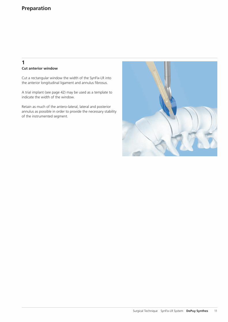
1Cut anterior window
Cut a rectangular window the width of the SynFix-LR into the anterior longitudinal ligament and annulus fibrosus.
A trial implant (see page 42) may be used as a template to indicate the width of the window.
Retain as much of the antero-lateral, lateral and posterior annulus as possible in order to provide the necessary stability of the instrumented segment.
Preparation

12 DePuy Synthes SynFix-LR System Surgical Technique
Preparation
2Prepare disc space
Recommended set
01.600.100 Proprep Set
Excise the disc material and remove the cartilaginous end-plates to expose the underlying bony vertebral endplates.
Adequate clearance of the endplates is important to enable the provision of a vascular supply to the bone graft.Excessive clearance or use of a rasp may, however, weaken the endplate and result in subsidence of the spacer.
Once the endplates have been prepared, complete eventual additional surgical procedures (i.e. removal of a disc fragment from the spinal canal).
Notes: – It is essential that the nucleus and the inner annulus are
removed to prevent displacement of disc material into the spinal canal during spacer insertion and interference with bone in-growth.
– Excessive removal of subchondral bone may weaken the vertebral endplate. If the entire endplate is removed, subsidence and a loss of segmental stability may result.

Surgical Technique SynFix-LR System DePuy Synthes 13
3Distract segment
Instrument
SFW650R Prodisc-L Spreader Forceps, curved
Optional instrument
SFW550R Prodisc-L Spreader
For a safe placement, verify spreader position with the help of an intraoperative lateral X-ray.
Distraction of the segment is essential for restoration of disc height, opening of the neural foramina and initial stability of the SynFix-LR.
4Trial for implant size
Instruments
03.802.000 – SynFix-LR Trial Implants 03.802.019
397.034 Handle for SynCage Trial Implants, straight
Optional instrument
397.113 Distractor, anterior, for SynCage-LR
Select the trial implant that corresponds with the SynFix-LR size determined during the preoperative planning. Attach it to the handle for trial implants. The handle must be tight-ened firmly to prevent loosening of the trial implant.
Note: Trials / Implants are color coded according to their size (height).

14 DePuy Synthes SynFix-LR System Surgical Technique
Controlled and light hammering on the handle for trial im-plants may be required to advance the trial implant into the disc space. If a tight fit is not achieved, repeat the process using larger trial implants. If the trial implant cannot be in-serted, repeat using smaller trial implants.
Alternatively, a distractor may be used to assist with guiding the trial implant into the disc space. To ensure that the implant is inserted symmetrically into the disc space, the central line on the distractor blades should be aligned with the anterior midline of the vertebral bodies. Slide the trial implant between the distractor blades into the disc space.
With the segment fully distracted, the trial implant (and final implant) must fit firmly with a tight press-fit between the endplates so that the disc height is not lost once the distrac-tor is removed.
The image intensifier may be used to check the position of the trial implant, restoration of disc and foraminal height and overall alignment before selecting the final SynFix-LRimplant size.
Notes: – Markings on the trial implant indicate the entry points of
the locking screws in the anterior aspect of the adjacent vertebrae.
– The distractor must be firmly held in place to prevent its ejection from the disc space and possible injury to adjacent structures.
– After impacting the trial spacer handle, it may be neces-sary to retighten the handle.
Markings indicate the entrypoints of the locking screws
Preparation
1
A
B
3
5
2
4
6
Surgical Technique SynFix-LR System DePuy Synthes 15
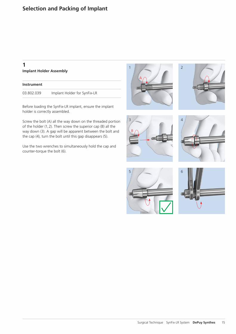
1Implant Holder Assembly
Instrument
03.802.039 Implant Holder for SynFix-LR
Before loading the SynFix-LR implant, ensure the implant holder is correctly assembled.
Screw the bolt (A) all the way down on the threaded portion of the holder (1, 2). Then screw the superior cap (B) all the way down (3). A gap will be apparent between the bolt and the cap (4), turn the bolt until this gap disappears (5).
Use the two wrenches to simultaneously hold the cap and counter-torque the bolt (6).
Selection and Packing of Implant

1
3
2
16 DePuy Synthes SynFix-LR System Surgical Technique
Selection and Packing of Implant
2Select implant size
Instruments
03.802.039 Implant Holder for SynFix-LR
E5211-3 Wrench Epoca width across 10
Precaution: Ensure the implant holder is correctly assembled and the cap and the bolt are counter-torqued using the two wrenches (see step 1 “Implant Holder Assembly” page 15 or “Disassembly and Assembly Instructions” pages 50–51).
Select the final SynFix-LR implant corresponding to the trial implant size (1).
To facilitate selection of the final implant, trial implants are laser etched with the nominal height, lordotic angle and footprint of the implant. Trial implants, aiming guides and fixation plates are color-coded (see page 40).
Attach the selected implant two-finger tight to the implant holder (2).
Precaution: Do not over-tighten the implant holder to the implant. Make sure the implant holder and the implant are aligned to each other and that no cross-threading occurs (3).
Surgical Technique SynFix-LR System DePuy Synthes 17
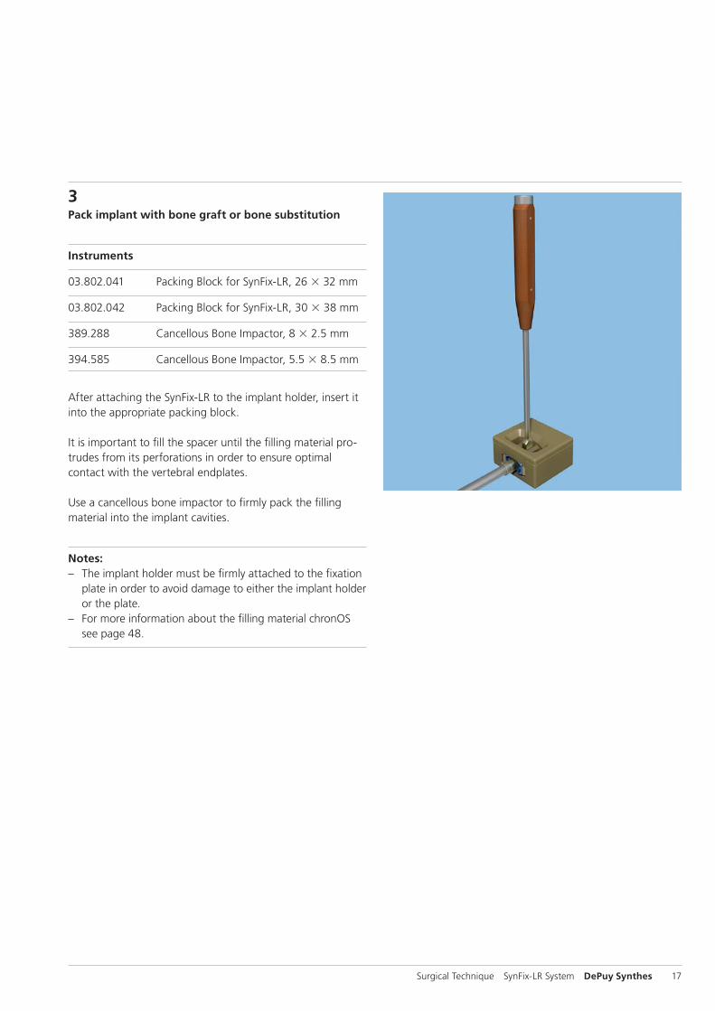
3Pack implant with bone graft or bone substitution
Instruments
03.802.041 Packing Block for SynFix-LR, 26 32 mm
03.802.042 Packing Block for SynFix-LR, 30 38 mm
389.288 Cancellous Bone Impactor, 8 2.5 mm
394.585 Cancellous Bone Impactor, 5.5 8.5 mm
After attaching the SynFix-LR to the implant holder, insert it into the appropriate packing block.
It is important to fill the spacer until the filling material pro-trudes from its perforations in order to ensure optimal contact with the vertebral endplates.
Use a cancellous bone impactor to firmly pack the filling material into the implant cavities.
Notes: – The implant holder must be firmly attached to the fixation
plate in order to avoid damage to either the implant holder or the plate.
– For more information about the filling material chronOS see page 48.
18 DePuy Synthes SynFix-LR System Surgical Technique
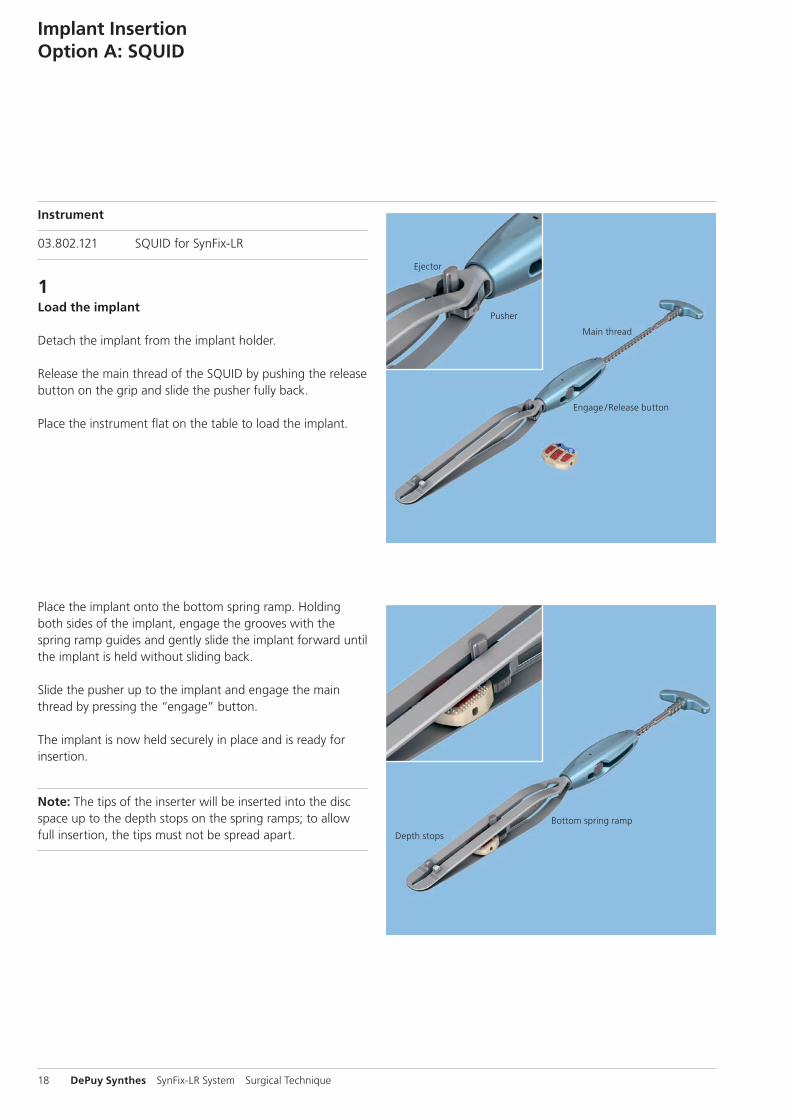
Instrument
03.802.121 SQUID for SynFix-LR
1Load the implant
Detach the implant from the implant holder.
Release the main thread of the SQUID by pushing the release button on the grip and slide the pusher fully back.
Place the instrument flat on the table to load the implant.
Place the implant onto the bottom spring ramp. Holding both sides of the implant, engage the grooves with the spring ramp guides and gently slide the implant forward until the implant is held without sliding back.
Slide the pusher up to the implant and engage the main thread by pressing the “engage” button.
The implant is now held securely in place and is ready for insertion.
Note: The tips of the inserter will be inserted into the disc space up to the depth stops on the spring ramps; to allow full insertion, the tips must not be spread apart.
Implant InsertionOption A: SQUID
Ejector
Pusher
Main thread
Engage / Release button
Depth stops
Bottom spring ramp
Surgical Technique SynFix-LR System DePuy Synthes 19
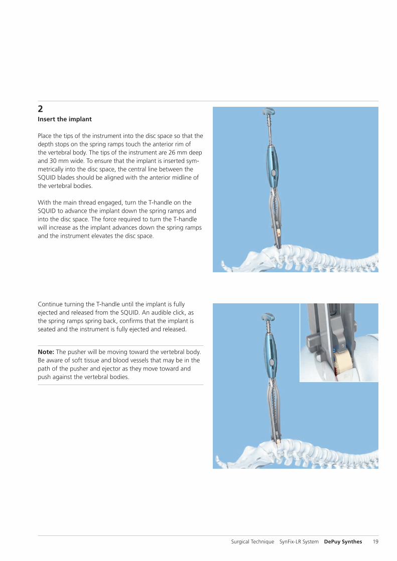
2Insert the implant
Place the tips of the instrument into the disc space so that the depth stops on the spring ramps touch the anterior rim of the vertebral body. The tips of the instrument are 26 mm deep and 30 mm wide. To ensure that the implant is inserted sym-metrically into the disc space, the central line between the SQUID blades should be aligned with the anterior midline of the vertebral bodies.
With the main thread engaged, turn the T-handle on the SQUID to advance the implant down the spring ramps and into the disc space. The force required to turn the T-handle will increase as the implant advances down the spring ramps and the instrument elevates the disc space.
Continue turning the T-handle until the implant is fully ejected and released from the SQUID. An audible click, as the spring ramps spring back, confirms that the implant is seated and the instrument is fully ejected and released.
Note: The pusher will be moving toward the vertebral body. Be aware of soft tissue and blood vessels that may be in the path of the pusher and ejector as they move toward and push against the vertebral bodies.

20 DePuy Synthes SynFix-LR System Surgical Technique
3Remove instruments
When the implant is correctly positioned, carefully remove the SQUID to avoid possible injury to adjacent structures.
Depending on the size of the vertebrae, the anterior edge of the implant will usually be 1 mm –3 mm recessed relative to the anterior aspect of the adjacent vertebrae.
4Verify final implant position
Verify final implant position with the help of an intraoperative lateral X-ray.
The titanium fixation plate and single posterior X-ray marker incorporated into the implant allow accurate intraoperative radiographic assessment of the position of the implant. The posterior X-ray marker is located approximately 3 mm from the posterior wall of the spacer.
Implant InsertionOption A: SQUID

Surgical Technique SynFix-LR System DePuy Synthes 21
Instrument
03.802.039 Implant Holder for SynFix-LR
Optional instrument
397.113 Distractor, anterior, for SynCage-LR
1Insert the implant
Insert the implant into the disc space.
Precaution: Ensure the implant holder remains tightened to the implant during the entire implant insertion procedure.
Controlled and light hammering on the implant holder may be required to advance the implant into the disc space. The implant must fit firmly with a tight press-fit between the endplates.
Alternatively, a distractor can be used to assist with guiding the implant into the disc space. To ensure that the implant is inserted symmetrically into the disc space, the central line on the distractor blades should be aligned with the anterior midline of the vertebral bodies.
Slide the implant between the distractor blades and into the disc space.
The image intensifier may be used to check the implant position, restoration of disc and foraminal height, and overall alignment.
Note: The distractor must be firmly held in place to prevent its ejection from the disc space and possible injury to adja-cent structures.
Implant InsertionOption B: Implant Holder

22 DePuy Synthes SynFix-LR System Surgical Technique
2Remove instruments
When the implant is correctly positioned, if the optional distractor was used, loosen the locking nut on the distractor handle and release the distraction.
Gently remove the distractor while the implant holder holds the implant in position.
After the distractor is removed, ensure a secure fit by lightly hammering on the implant holder.
Precaution: Ensure the implant holder remains tightened to the implant during the entire implant insertion procedure.
Remove the implant holder by rotating the handle counter-clockwise. The implant should now be in its optimal position.
Precaution: If increased resistance is encountered during detachment, remove the implant holder with the implant attached. In case of a jammed connection between implant and implant holder detach the implant holder from the im-plant using one wrench to hold the cap while detaching the implant. Restart the implant insertion procedure with step 1 “Implant Holder Assembly” on page 15.
Depending on the size of the vertebrae, the anterior edge of the implant will usually be 1 mm–3 mm recessed relative to the anterior aspect of the adjacent vertebrae.
3Verify final implant position
Verify final implant position with the help of an intraoperative lateral X-ray.
The titanium fixation plate and single posterior X-ray marker incorporated into the implant allow accurate intraoperative radiographic assessment of the position of the implant. The posterior X-ray marker is located approximately 3 mm from the posterior wall of the spacer.
Implant InsertionOption B: Implant Holder
Surgical Technique SynFix-LR System DePuy Synthes 23
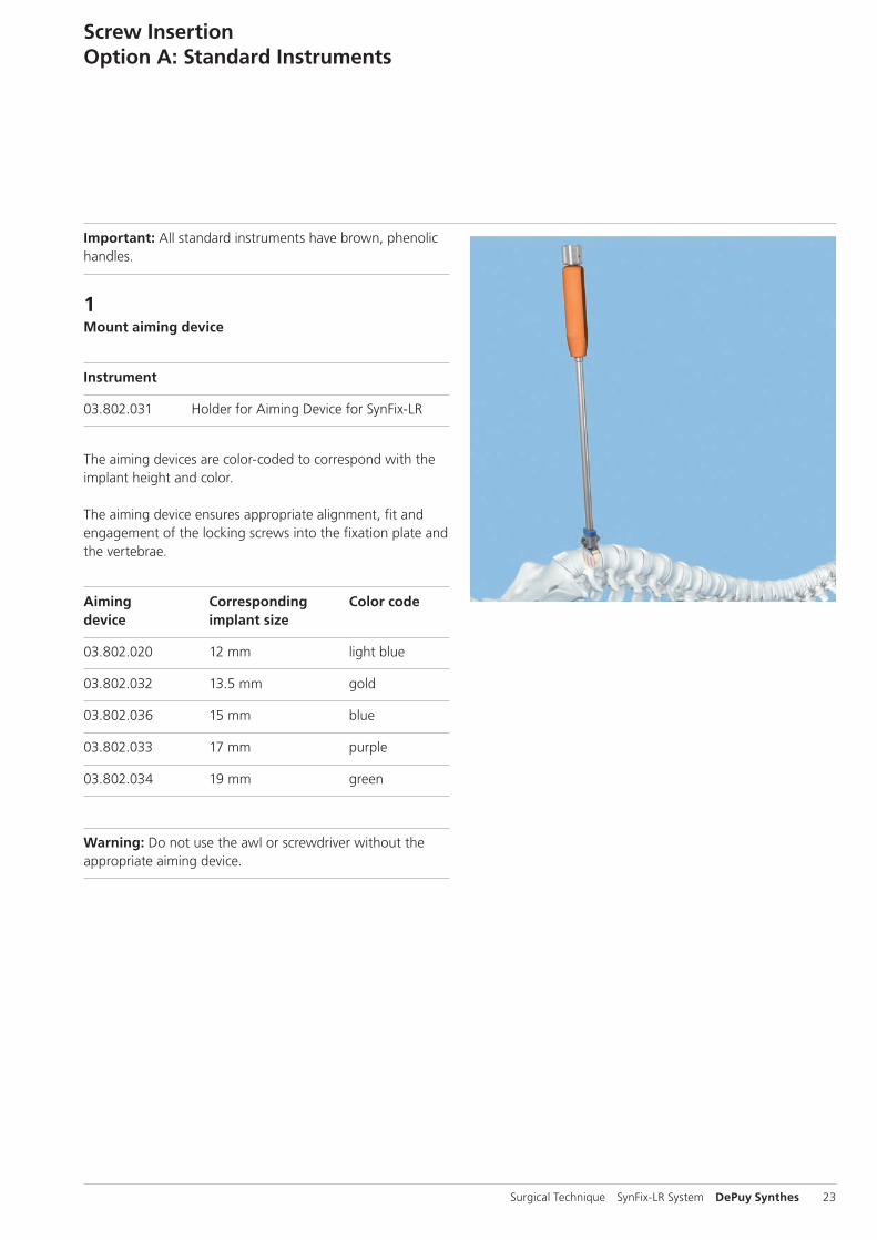
Important: All standard instruments have brown, phenolic handles.
1 Mount aiming device
Instrument
03.802.031 Holder for Aiming Device for SynFix-LR
The aiming devices are color-coded to correspond with the implant height and color.
The aiming device ensures appropriate alignment, fit and engagement of the locking screws into the fixation plate and the vertebrae.
Aiming Corresponding Color codedevice implant size
03.802.020 12 mm light blue
03.802.032 13.5 mm gold
03.802.036 15 mm blue
03.802.033 17 mm purple
03.802.034 19 mm green
Warning: Do not use the awl or screwdriver without the appropriate aiming device.
Screw InsertionOption A: Standard Instruments

c
ab
24 DePuy Synthes SynFix-LR System Surgical Technique
Optional: The modified aiming device for SynFix-LR allows working through a smaller incision compared to the aiming device mentioned above (see also page 46).
Modified Corresponding Color code aiming device implant size
03.802.242 12 mm light blue
03.802.243 13.5 mm gold
03.802.245 15 mm blue
03.802.247 17 mm purple
03.802.249 19 mm green
Choose the corresponding aiming device and attach the aim-ing device holder.
Insert the aiming device.
Position the aiming device so that the threaded pin (a) fits into the central hole of the fixation plate and the lateral posi-tioning pin (b) aligns with one of the the plate holes for the fixation screw.
When the aiming device has been positioned, secure it by tightening the nut (c) on top of the aiming device holder.
Precaution: If the aiming device cannot be secured to the implant, remove the implant and replace it with a new implant (continue with section “Implant Removal”, p. 38).
Notes: – The aiming device should fit snugly against the plate.
Do not overtighten. – As the guiding distance of the modified aiming device is
shorter than the guiding distance of the standard aiming device, take care to maintain alignment of the awl and screwdriver (see page 46).
Screw InsertionOption A: Standard Instruments
Surgical Technique SynFix-LR System DePuy Synthes 25
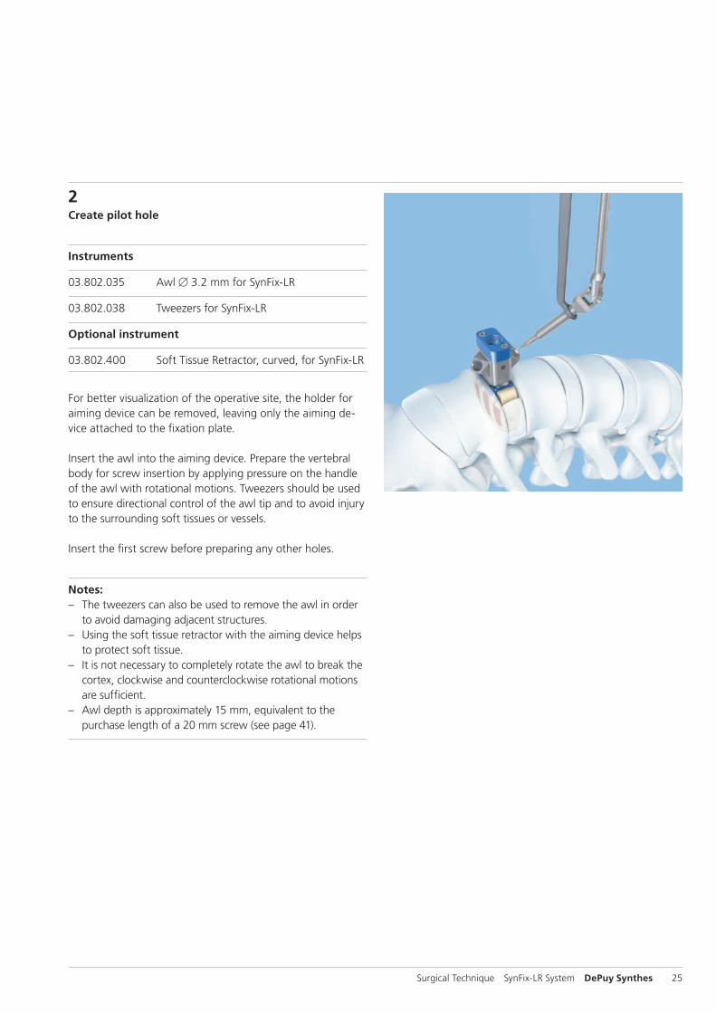
2Create pilot hole
Instruments
03.802.035 Awl B 3.2 mm for SynFix-LR
03.802.038 Tweezers for SynFix-LR
Optional instrument
03.802.400 Soft Tissue Retractor, curved, for SynFix-LR
For better visualization of the operative site, the holder for aiming device can be removed, leaving only the aiming de-vice attached to the fixation plate.
Insert the awl into the aiming device. Prepare the vertebral body for screw insertion by applying pressure on the handle of the awl with rotational motions. Tweezers should be used to ensure directional control of the awl tip and to avoid injury to the surrounding soft tissues or vessels.
Insert the first screw before preparing any other holes.
Notes: – The tweezers can also be used to remove the awl in order
to avoid damaging adjacent structures. – Using the soft tissue retractor with the aiming device helps
to protect soft tissue. – It is not necessary to completely rotate the awl to break the
cortex, clockwise and counterclockwise rotational motions are sufficient.
– Awl depth is approximately 15 mm, equivalent to the purchase length of a 20 mm screw (see page 41).

26 DePuy Synthes SynFix-LR System Surgical Technique
3Insert and tighten first screw
Instruments
03.802.037 Screwdriver for SynFix-LR
03.802.038 Tweezers for SynFix-LR
Select the appropriate screw length (20 mm screws are re-commended for use in most cases). Screw length should be selected to penetrate completely through the cortical bone. For a two-level procedure, proper consideration should be given to the screw length on the common vertebral body to prevent screw interference. The tweezers allow control of the screw during insertion to avoid damage to the surroun-ding soft tissue or vessels.
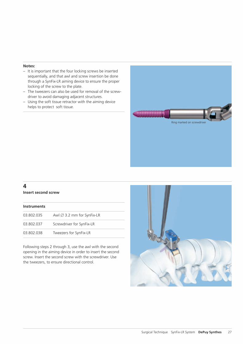
Insert the self-tapping screw through the aiming device and into the pilot hole created by the awl. As soon as the ring marked on the screwdriver meets the entry point of the aim-ing device, the locking position of the screw within the fixa-tion plate has been approximately reached.
Tighten the screw firmly.
Warning: Excessive torque can damage or break the instruments or implant.
Screw InsertionOption A: Standard Instruments
Surgical Technique SynFix-LR System DePuy Synthes 27
Ring marked on screwdriver
4Insert second screw
Instruments
03.802.035 Awl B 3.2 mm for SynFix-LR
03.802.037 Screwdriver for SynFix-LR
03.802.038 Tweezers for SynFix-LR
Following steps 2 through 3, use the awl with the second opening in the aiming device in order to insert the second screw. Insert the second screw with the screwdriver. Use the tweezers, to ensure directional control.
Notes: – It is important that the four locking screws be inserted
sequentially, and that awl and screw insertion be done through a SynFix-LR aiming device to ensure the proper locking of the screw to the plate.
– The tweezers can also be used for removal of the screw-driver to avoid damaging adjacent structures.
– Using the soft tissue retractor with the aiming device helps to protect soft tissue.

1
2
28 DePuy Synthes SynFix-LR System Surgical Technique
5Rotate aiming device
Instrument
03.802.031 Holder for Aiming Device for SynFix-LR
If the holder for the aiming device has been removed, reat-tach it to the aiming device before rotation.
Loosen the aiming device by turning the nut (1) counter-clockwise four to five times. The aiming device can be ro-tated 180°, without disengaging it completely from the fixa-tion plate (2).
Relock the aiming device by turning the nut (1) clockwise.
Notes: – If the aiming device is difficult to rotate, verify that the
screws are advanced far enough and are not blocking the aiming device during rotation.
– Rotating the aiming device clockwise will ensure that the aiming device handle does not loosen unintentionally.
– The aiming device should fit snugly against the plate. Do not overtighten.
Screw InsertionOption A: Standard Instruments

Surgical Technique SynFix-LR System DePuy Synthes 29
7Remove instruments
When the implant is secured, remove the aiming device by turning the nut on top of the aiming device holder.
Note: If the aiming device is difficult to remove, verify that the screws are advanced far enough and are not blocking the aiming device during removal.
6Insert third and fourth screws
For insertion of the third and fourth screws, repeat steps 2 through 4.
Notes: – Four (4) screws should always be used for every SynFix-LR
construct. – If less than four screws are inserted, a supplemental fixa-
tion is mandatory.
30 DePuy Synthes SynFix-LR System Surgical Technique
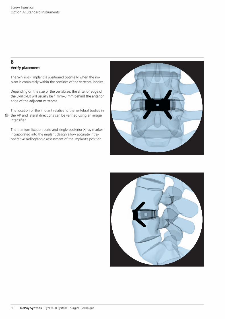
8Verify placement
The SynFix-LR implant is positioned optimally when the im-plant is completely within the confines of the vertebral bodies.
Depending on the size of the vertebrae, the anterior edge of the SynFix-LR will usually be 1 mm–3 mm behind the anterior edge of the adjacent vertebrae.
The location of the implant relative to the vertebral bodies in the AP and lateral directions can be verified using an image intensifier.
The titanium fixation plate and single posterior X-ray marker incorporated into the implant design allow accurate intra-operative radiographic assessment of the implant’s position.
Screw InsertionOption A: Standard Instruments

Surgical Technique SynFix-LR System DePuy Synthes 31
Important: All mini-open instruments have green, silicone handles.
1 Mount aiming device
Instrument
03.802.200 Coupling for Mini-Open Aiming Device, with fixed handle, for SynFix-LR
The aiming devices are color-coded to correspond with the implant height and the plate color.
Fixed handle Corresponding Color codeaiming device implant size
03.802.202 12 mm light blue
03.802.203 13.5 mm gold
03.802.205 15 mm blue
03.802.207 17 mm purple
03.802.209 19 mm green
The aiming device ensures appropriate alignment, fit and engagement of the locking screws into the fixation plate and the vertebrae.
Choose the corresponding aiming device and attach the implant coupling.
Insert the aiming device.
Warning: Do not use the awl or screwdriver without the appropriate aiming device.
Screw InsertionOption B: Mini-Open Instruments
Implant coupling Fixed-handle aiming device
ba
32 DePuy Synthes SynFix-LR System Surgical Technique
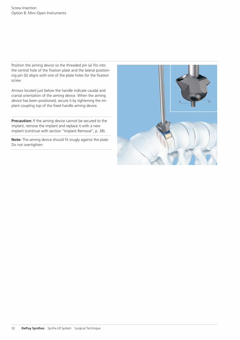
Position the aiming device so the threaded pin (a) fits into the central hole of the fixation plate and the lateral position-ing pin (b) aligns with one of the plate holes for the fixation screw.
Arrows located just below the handle indicate caudal and cranial orientation of the aiming device. When the aiming device has been positioned, secure it by tightening the im-plant coupling top of the fixed handle aiming device.
Precaution: If the aiming device cannot be secured to the implant, remove the implant and replace it with a new implant (continue with section “Implant Removal”, p. 38).
Note: The aiming device should fit snugly against the plate. Do not overtighten.
Screw InsertionOption B: Mini-Open Instruments

Surgical Technique SynFix-LR System DePuy Synthes 33
2Create pilot hole
Instrument
03.802.230 Awl B 3.2 mm for SynFix-LR Mini-Open
Optional instruments
03.802.038 Tweezers for SynFix-LR
03.802.400 Soft Tissue Retractor, curved, for SynFix-LR
Insert the awl into the aiming device. Prepare the vertebral body for screw insertion by applying pressure on the handle of the awl with rotational motions.
Insert the first screw before preparing any other holes.
Notes: – It is not necessary to completely rotate the awl to break
the cortex, rotational motions clockwise and counterclock-wise are sufficient.
– The awl for SynFix-LR mini-open features a tip with posi-tional memory. There is no need to use tweezers to control the tip while inserting into the aiming device; however, the tweezers can be used as an option.
– Awl depth is approximately 10 mm, equivalent to the purchase length of a 15 mm screw.
– Using the soft tissue retractor with the aiming device helps to protect soft tissue.
34 DePuy Synthes SynFix-LR System Surgical Technique
Ring marked on screwdriver
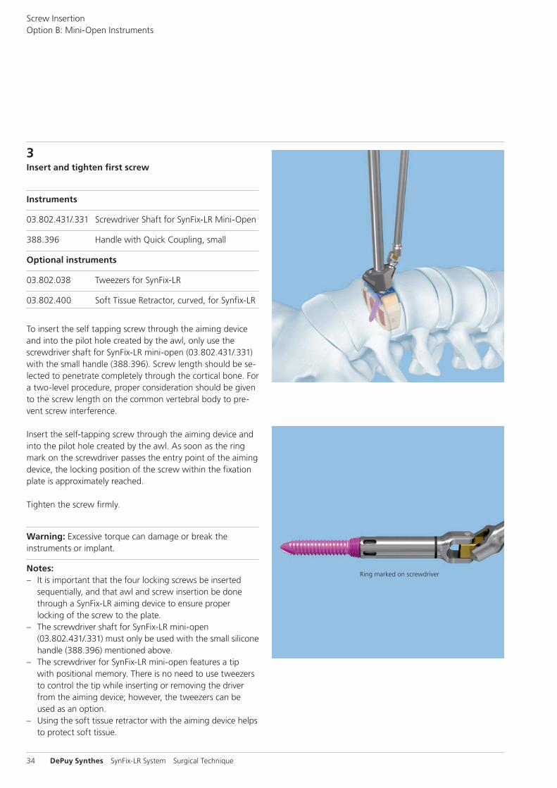
3Insert and tighten first screw
Instruments
03.802.431/.331 Screwdriver Shaft for SynFix-LR Mini-Open
388.396 Handle with Quick Coupling, small
Optional instruments
03.802.038 Tweezers for SynFix-LR
03.802.400 Soft Tissue Retractor, curved, for Synfix-LR
To insert the self tapping screw through the aiming device and into the pilot hole created by the awl, only use the screwdriver shaft for SynFix-LR mini-open (03.802.431/.331) with the small handle (388.396). Screw length should be se-lected to penetrate completely through the cortical bone. For a two-level procedure, proper consideration should be given to the screw length on the common vertebral body to pre-vent screw interference.
Insert the self-tapping screw through the aiming device and into the pilot hole created by the awl. As soon as the ring mark on the screwdriver passes the entry point of the aiming device, the locking position of the screw within the fixation plate is approximately reached.
Tighten the screw firmly.
Warning: Excessive torque can damage or break the instruments or implant.
Notes: – It is important that the four locking screws be inserted
sequentially, and that awl and screw insertion be done through a SynFix-LR aiming device to ensure proper locking of the screw to the plate.
– The screwdriver shaft for SynFix-LR mini-open (03.802.431/.331) must only be used with the small silicone handle (388.396) mentioned above.
– The screwdriver for SynFix-LR mini-open features a tip with positional memory. There is no need to use tweezers to control the tip while inserting or removing the driver from the aiming device; however, the tweezers can be used as an option.
– Using the soft tissue retractor with the aiming device helps to protect soft tissue.
Screw InsertionOption B: Mini-Open Instruments

1
2
Surgical Technique SynFix-LR System DePuy Synthes 35
5Rotate aiming device
Loosen the aiming device by turning the nut (1) counterclock-wise four to five turns. The aiming device can be rotated 180° without disengaging completely from the fixation plate (2).
Arrows located just below the handle indicate caudal andcranial orientation of the aiming device.
Relock the aiming device by turning the nut (1) clockwise.
Notes: – If the aiming device is difficult to rotate, verify that the
screws are advanced far enough and are not blocking the aiming device during rotation.
– The fixed-handle aiming device can be rotated in either direction.
– The aiming device should fit snugly against the plate. Do not overtighten.
4Insert second screw
Instruments
03.802.230 Awl B 3.2 mm for SynFix-LR mini-open
03.802.431/.331 Screwdriver Shaft for SynFix-LR mini-open
388.396 Handle with Quick Coupling, small
Following steps 2 through 3, use the awl with the second opening in the aiming device in order to insert the second screw. Insert the second screw with the screwdriver.

36 DePuy Synthes SynFix-LR System Surgical Technique
6Insert third and fourth screws
For insertion of the third and fourth screws, repeatsteps 2 through 4.
Notes: – Four (4) screws should always be used for every SynFix-LR
construct. – If less than four screws are inserted, a supplemental fixa-
tion is mandatory.
7Remove instruments
When the implant is secured, remove the aiming device by turning the nut on top of the fixed handle aiming device.
Note: If the aiming device is difficult to remove, verify that the screws are advanced far enough and are not blocking the aiming device during removal.
Screw InsertionOption B: Mini-Open Instruments
Surgical Technique SynFix-LR System DePuy Synthes 37
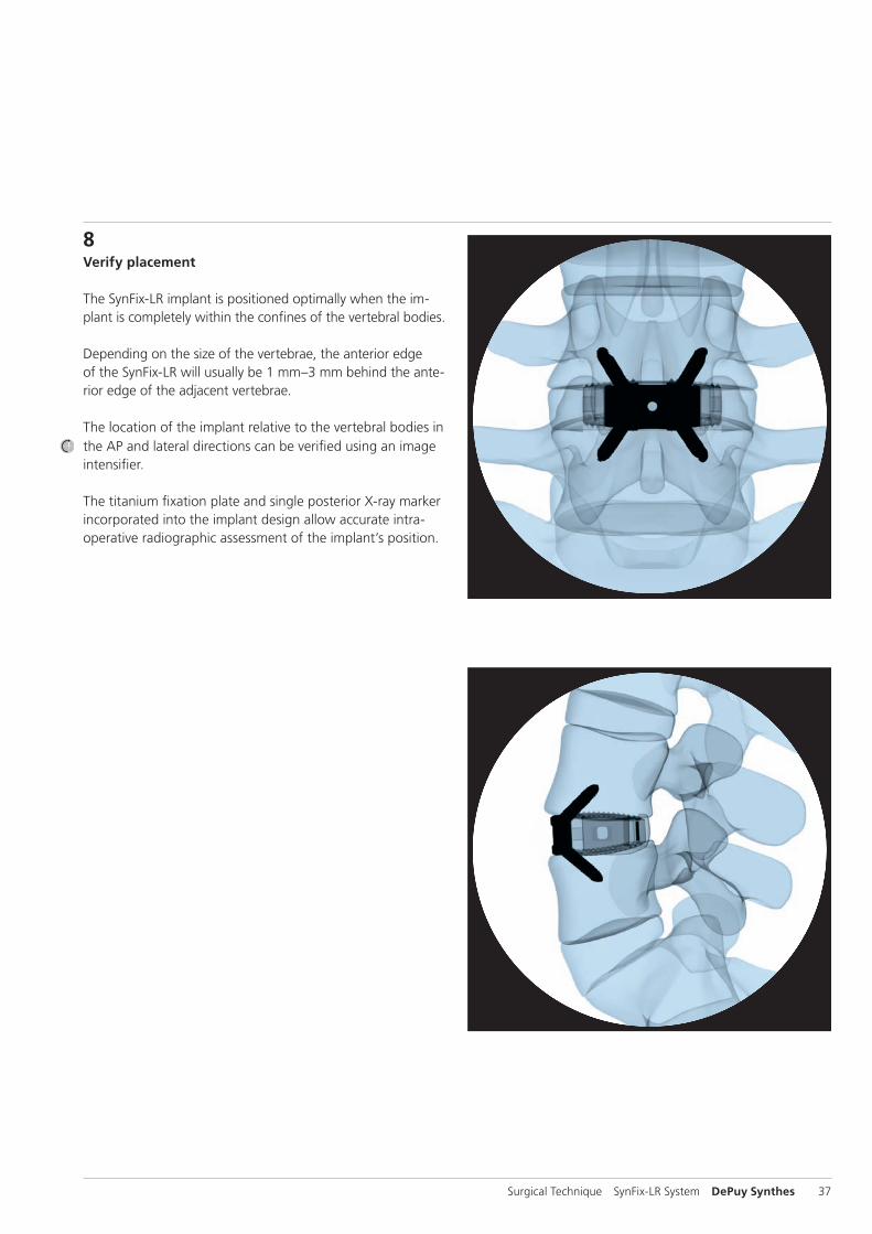
8Verify placement
The SynFix-LR implant is positioned optimally when the im-plant is completely within the confines of the vertebral bodies.
Depending on the size of the vertebrae, the anterior edge of the SynFix-LR will usually be 1 mm–3 mm behind the ante-rior edge of the adjacent vertebrae.
The location of the implant relative to the vertebral bodies in the AP and lateral directions can be verified using an image intensifier.
The titanium fixation plate and single posterior X-ray marker incorporated into the implant design allow accurate intra -operative radiographic assessment of the implant’s position.

38 DePuy Synthes SynFix-LR System Surgical Technique
1Approach the Implant
Instrument
388.407 Holding Forceps for Rods B 3.5 mm, length 181 mm
Make sure to remove all screws prior to usage of holding forceps.In case the implant needs to be removed out of the interver-tebral disc space, the holding forceps 388.407 can be used alternatively to the implant holder 03.802.039. Check all four available bridges of the SynFix-LR implant prior removal. Choose a bridge that is easy to access. Approach the implant with the holding forceps in opened condition.
Note: In case the accessibility of the bridge is limited due to bony structures, remove them with appropriate instrumenta-tion.
2Connect Forceps to Implant
Grab the bridge with the holding forceps and lock it by scrunching the levers of the forceps.
3Remove Implant
Apply a gentle extraction force to the holding forceps to remove the implant. Ensure after removal of the implant that all components were removed out of the intervertebral disc space.
Note: Reuse of implant is not recommended due to possible damage to the conical thread of the plate after extraction.
Implant Removal

Surgical Technique SynFix-LR System DePuy Synthes 39
Postoperative management
Patients can usually be mobilized once they regain muscular control of their trunk on the same day or one day after surgery. As no supplementary posterior fixation is required, surgical morbidity and post-operative discomfort are likely to be reduced. Patients may be inclined to increase activities quite rapidly. However, patients should be cautioned against activities that place unreasonable stress on the lower back until solid bony union has been achieved.
Excessive physical activity and trauma may result in failure, with subsidence of the implant and/or the development of a non-union. Loss of fixation may also occur if excessive activity and motion is attempted prior to restoration of good lumbar trunk and abdominal muscle control and function.
40 DePuy Synthes SynFix-LR System Surgical Technique
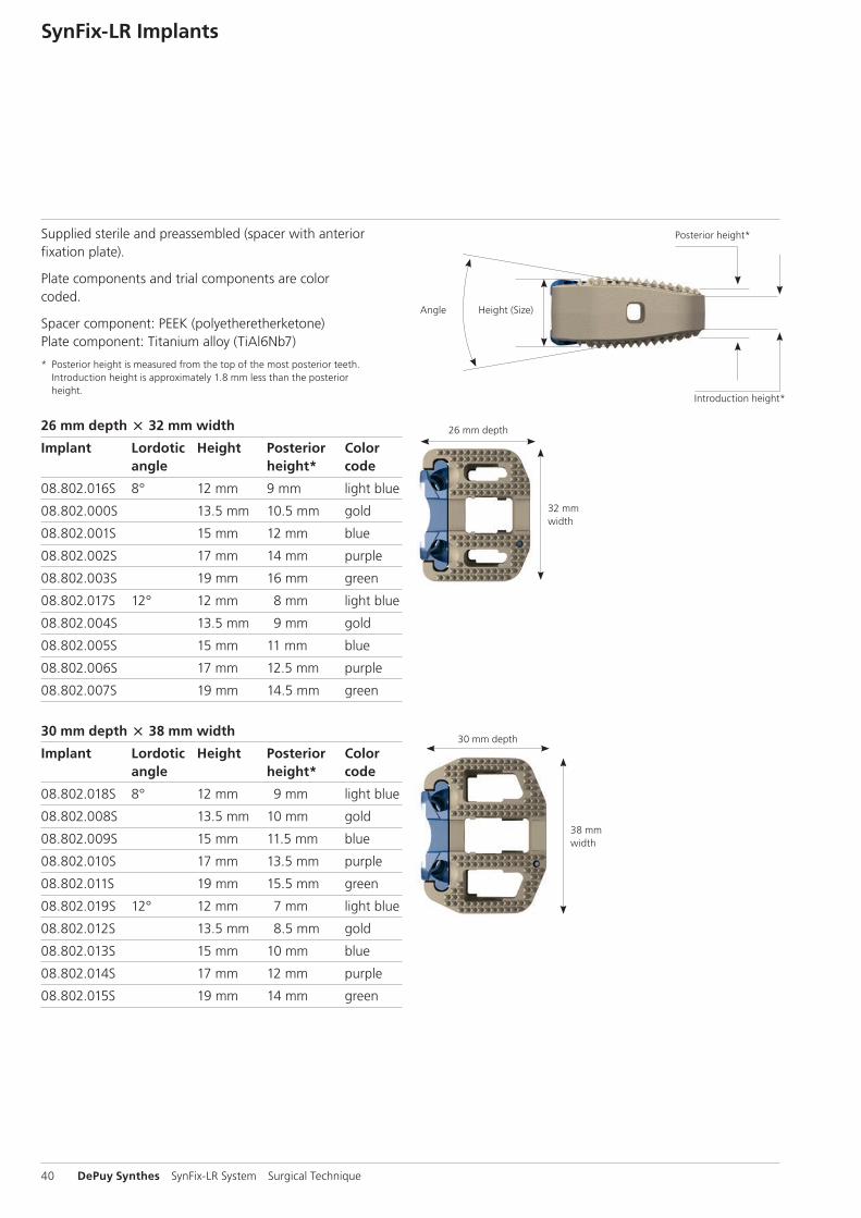
Supplied sterile and preassembled (spacer with anterior fixation plate).
Plate components and trial components are colorcoded.
Spacer component: PEEK (polyetheretherketone)Plate component: Titanium alloy (TiAl6Nb7)
* Posterior height is measured from the top of the most posterior teeth. Introduction height is approximately 1.8 mm less than the posterior height.
26 mm depth 32 mm width
Implant Lordotic Height Posterior Color angle height* code
08.802.016S 8° 12 mm 9 mm light blue
08.802.000S 13.5 mm 10.5 mm gold
08.802.001S 15 mm 12 mm blue
08.802.002S 17 mm 14 mm purple
08.802.003S 19 mm 16 mm green
08.802.017S 12° 12 mm 8 mm light blue
08.802.004S 13.5 mm 9 mm gold
08.802.005S 15 mm 11 mm blue
08.802.006S 17 mm 12.5 mm purple
08.802.007S 19 mm 14.5 mm green
30 mm depth 38 mm width
Implant Lordotic Height Posterior Color angle height* code
08.802.018S 8° 12 mm 9 mm light blue
08.802.008S 13.5 mm 10 mm gold
08.802.009S 15 mm 11.5 mm blue
08.802.010S 17 mm 13.5 mm purple
08.802.011S 19 mm 15.5 mm green
08.802.019S 12° 12 mm 7 mm light blue
08.802.012S 13.5 mm 8.5 mm gold
08.802.013S 15 mm 10 mm blue
08.802.014S 17 mm 12 mm purple
08.802.015S 19 mm 14 mm green
SynFix-LR Implants
Posterior height*
26 mm depth
30 mm depth
32 mm width
38 mm width
Height (Size)Angle
Introduction height*

Surgical Technique SynFix-LR System DePuy Synthes 41
4.0 mm locking implant screws Self-tappingTitanium Alloy (TiAl6Nb7)
Screw Length Bone purchase*
04.802.200 15 mm 10 mm
04.802.201 20 mm 15 mm
04.802.202 25 mm 20 mm
04.802.203 30 mm 25 mm
4.0 mm locking implant screws fine tipSelf-tappingTitanium Alloy (TiAI6Nb7)
Screw fine tip Length Bone purchase*
04.802.210 15 mm 10 mm
04.802.211 20 mm 15 mm
04.802.212 25 mm 20 mm
04.802.213 30 mm 25 mm
Fine tip screws are more pointed and therefore easier to use in dense sclerotic bone.
SynFix-LR Screws
*Bone purchase
*Bone purchase
Length
Length

42 DePuy Synthes SynFix-LR System Surgical Technique
Trial implantsColor coded by size (same color as the SynFix-LR implantplate component).
26 mm depth 32 mm width
Implant Lordotic Height Color angle code
03.802.016 8° 12 mm light blue
03.802.000 13.5 mm gold
03.802.001 15 mm blue
03.802.002 17 mm purple
03.802.003 19 mm green
03.802.017 12° 12 mm light blue
03.802.004 13.5 mm gold
03.802.005 15 mm blue
03.802.006 17 mm purple
03.802.007 19 mm green
30 mm depth 38 mm width
Implant Lordotic Height Color angle code
03.802.018 8° 12 mm light blue
03.802.008 13.5 mm gold
03.802.009 15 mm blue
03.802.010 17 mm purple
03.802.011 19 mm green
03.802.019 12° 12 mm light blue
03.802.012 13.5 mm gold
03.802.013 15 mm blue
03.802.014 17 mm purple
03.802.015 19 mm green
SynFix-LR Trial Implants
26 mm depth
30 mm depth
32 mm width
38 mm width

Surgical Technique SynFix-LR System DePuy Synthes 43
397.034 Handle for SynCage Trial Implants, straight
397.113 Distractor, anterior, for SynCage-LR
03.802.031 Holder for Aiming Device for SynFix-LR
03.802.035 Awl B 3.2 mm for SynFix-LR
03.802.041 Packing Block for SynFix-LR, 26 32 mm03.802.042 Packing Block for SynFix-LR, 30 38 mm
389.288 Cancellous Bone Impactor for Travios and Plivios, 8 2.5 mm
394.585 Cancellous Bone Impactor, 5.5 8.5 mm
SynFix-LR Instruments

44 DePuy Synthes SynFix-LR System Surgical Technique
03.802.037 Screwdriver for SynFix-LR
03.802.038 Tweezers for SynFix-LR
03.802.039 Implant Holder for SynFix-LR
388.407 Holding Forceps for Rods B 3.5 mm, length 181 mm
SFW650R Prodisc-L Spreader Forceps, curved
SFW550R Prodisc-L Spreader
SynFix-LR Instruments
388.311 Screwdriver T15, length 300 mm

Surgical Technique SynFix-LR System DePuy Synthes 45
03.802.121 SQUID for SynFix-LR
03.802.200 Coupling for mini-open Aiming Device, with fixed handle, for SynFix-LR
03.802.400 Soft Tissue Retractor, curved, for SynFix-LR
03.802.230 Awl B 3.2 mm for SynFix-LR mini-open
03.802.431 Screwdriver Shaft for SynFix-LR mini-open, with tapered Tip
388.396 Handle with Quick Coupling, small
E5211-3 Wrench Epoca width across 10 mm

~4.3 cm
46 DePuy Synthes SynFix-LR System Surgical Technique
Standard aiming device (required exposure 8–10 cm)
03.802.020 Aiming Device for SynFix-LR, 12 mm, light blue
03.802.032 Aiming Device for SynFix-LR, 13.5 mm, gold
03.802.036 Aiming Device for SynFix-LR, 15 mm, blue
03.802.033 Aiming Device for SynFix-LR, 17 mm, purple
03.802.034 Aiming Device for SynFix-LR, 19 mm, green
If a standard aiming device is used, a radius of ~4.3 cm is required. This device enables a good guidance of the awl and the screwdriver while ensuring a secure insertion of all screws.
Modified aiming device (required exposure 7–9 cm)
Optional:
03.802.242 Aiming Device, modified, for SynFix-LR, 12 mm, light blue
03.802.243 Aiming Device, modified, for SynFix-LR, 13.5 mm, gold
03.802.245 Aiming Device, modified, for SynFix-LR, 15 mm, blue
03.802.247 Aiming Device, modified, for SynFix-LR, 17 mm, purple
03.802.249 Aiming Device, modified, for SynFix-LR, 19 mm, green
The modifi ed aiming device has a relief that allows the awl to be inserted more toward the center, similar to the mini-open instruments. The red shaded area indicates the change made to the standard aiming device.
SynFix-LR Aiming Devices
Guidance is established just before the awl penetrates the cortex.

~2.7 cm
Surgical Technique SynFix-LR System DePuy Synthes 47
Trade-off between guidance and exposureThere is a trade-off between guidance and exposure. The standard aiming device offers the best guidance but also requires a larger exposure. The aiming device mini-open requires a smaller exposure, but the guidance is decreased.
Compared to the standard aiming device, the modified aim-ing device allows less angulation when inserting the awl or the screwdriver. During the insertion of the instrument, less space is needed.
Aiming device mini-open with fixed handle (required exposure 5–7 cm)
03.802.202 Aiming Device mini-open, with fixed handle, for SynFix-LR, 12 mm
03.802.203 Aiming Device mini-open, with fixed handle, for SynFix-LR, 13.5 mm
03.802.205 Aiming Device mini-open, with fixed handle, for SynFix-LR, 15 mm
03.802.207 Aiming Device mini-open, with fixed handle, for SynFix-LR, 17 mm
03.802.209 Aiming Device mini-open, with fixed handle, for SynFix-LR, 19 mm
If an aiming device mini-open with fixed handle is used, a radius of ~2.7 cm is required. It enables a good guidance of the awl and the screwdriver while ensuring a secure inser-tion of all screws.
Standard aiming device Modified aiming device Aiming device mini-open
48 DePuy Synthes SynFix-LR System Surgical Technique
Synthetic cancellous bone graft substitute: chronOS Bone Void FillerchronOS Bone Void Filler is a bone graft substitute consisting of pure ß-tricalcium phosphate. Its compressive strength is similar to that of cancellous bone once it has been incorpo-rated and remodeled.1 Based on literature, the use of ß-tri-calcium phosphate in the spinal column is a valuable alterna-tive to allografts and autografts, even when larger amounts are required.2,3
ResorbableIt is being replaced in the human body by host bone in 6 to 18 months; depending on the indication and the patient’s conditions.2,4-6
OsteoconductiveInterconnected macropores of defined size (100–500 μm)facilitate bone formation throughout the entire implant. Interconnected micropores (<10 μm) allow an optimal supply of nutrients.1,7
Osteoinductive with bone marrow The combination of chronOS Bone Void Filler with bone marrow accelerates and enhances osteointegration.4,5
SyntheticHaving a synthetic origin, chronOS Bone Void Filler offers the advantage of uniform quality and unlimited availability.
1 Gazdag et al. 19952 Muschik et al. 20013 Knop et al. 20064 Stoll et al. 20045 Becker et al. 20066 Wheeler et al. 20057 Lu et al. 1999
Filling Material
Surgical Technique SynFix-LR System DePuy Synthes 49
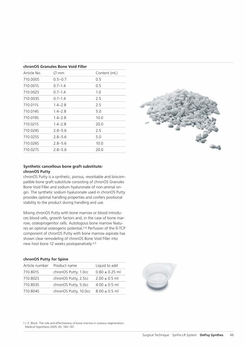
chronOS Granules Bone Void Filler
Article No. B mm Content (mL)
710.000S 0.5–0.7 0.5
710.001S 0.7–1.4 0.5
710.002S 0.7–1.4 1.0
710.003S 0.7–1.4 2.5
710.011S 1.4–2.8 2.5
710.014S 1.4–2.8 5.0
710.019S 1.4–2.8 10.0
710.021S 1.4–2.8 20.0
710.024S 2.8–5.6 2.5
710.025S 2.8–5.6 5.0
710.026S 2.8–5.6 10.0
710.027S 2.8–5.6 20.0
Synthetic cancellous bone graft substitute: chronOS PuttychronOS Putty is a synthetic, porous, resorbable and biocom-patible bone graft substitute consisting of chronOS Granules Bone Void Filler and sodium hyaluronate of non-animal ori-gin. The synthetic sodium hyaluronate used in chronOS Putty provides optimal handling properties and confers positional stability to the product during handling and use.
Mixing chronOS Putty with bone marrow or blood introdu-ces blood cells, growth factors and, in the case of bone mar-row, osteoprogenitor cells. Autologous bone marrow featu-res an optimal osteogenic potential.5,8 Perfusion of the ß-TCP component of chronOS Putty with bone marrow aspirate has shown clear remodeling of chronOS Bone Void Filler into new host bone 12 weeks postoperatively.4,5
chronOS Putty for Spine
Article number Product name Liquid to add
710.801S chronOS Putty, 1.0cc 0.80 ± 0.25 ml
710.802S chronOS Putty, 2.5cc 2.00 ± 0.5 ml
710.803S chronOS Putty, 5.0cc 4.00 ± 0.5 ml
710.804S chronOS Putty, 10.0cc 8.00 ± 0.5 ml
8 J. E. Block. The role and effectiveness of bone marrow in osseous regeneration. Medical Hypothesis 2005; 65: 740–747.
50 DePuy Synthes SynFix-LR System Surgical Technique
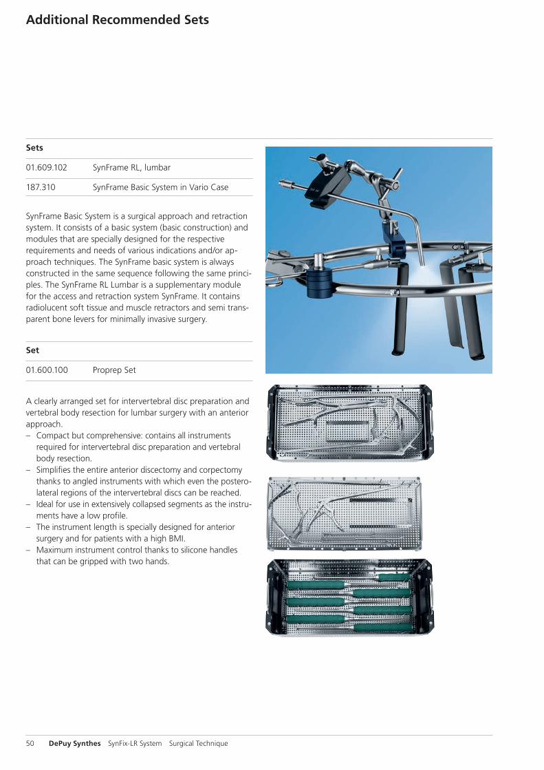
Sets
01.609.102 SynFrame RL, lumbar
187.310 SynFrame Basic System in Vario Case
SynFrame Basic System is a surgical approach and retraction system. It consists of a basic system (basic construction) and modules that are specially designed for the respective require ments and needs of various indications and/or ap-proach techniques. The SynFrame basic system is always constructed in the same sequence following the same princi-ples. The SynFrame RL Lumbar is a supplementary module for the access and retraction system SynFrame. It contains radiolucent soft tissue and muscle retractors and semi trans-parent bone levers for minimally invasive surgery.
Set
01.600.100 Proprep Set
A clearly arranged set for intervertebral disc preparation and vertebral body resection for lumbar surgery with an anterior approach. – Compact but comprehensive: contains all instruments
required for intervertebral disc preparation and vertebral body resection.
– Simplifies the entire anterior discectomy and corpectomy thanks to angled instruments with which even the postero-lateral regions of the intervertebral discs can be reached.
– Ideal for use in extensively collapsed segments as the instru- ments have a low profile.
– The instrument length is specially designed for anterior surgery and for patients with a high BMI.
– Maximum instrument control thanks to silicone handles that can be gripped with two hands.
Additional Recommended Sets

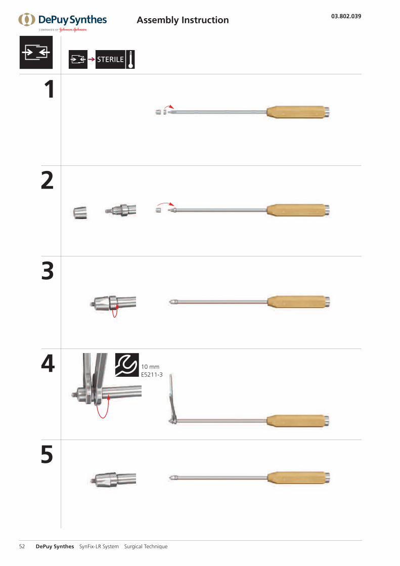
1
2
3
4
03.802.039
SE_4
3109
8 A
B ©
03/
2014
Sy
nthe
s, In
c. o
r its
aff
iliat
es
All
right
s re
serv
ed
Page 1/2
10 mm E5211-3
Surgical Technique SynFix-LR System DePuy Synthes 51
Disassembly Instruction
1
2
3
4
5
03.802.039SE
_431
098
AB
© 0
3/20
14
Synt
hes,
Inc.
or
its a
ffili
ates
A
ll rig
hts
rese
rved
Page 2/2
10 mm E5211-3
52 DePuy Synthes SynFix-LR System Surgical Technique
Assembly Instruction

Surgical Technique SynFix-LR System DePuy Synthes 53
Aebi M, Arlet V, Webb JK (2007): AOSPINE Manual (2 vols), Stuttgart, New York: Thieme
Arlet V, Jiang L, Steffen T, Ouellet J, Reindl R, Aebi M (2006): Harvesting local cylinder autograft from adjacent vertebral body for anterior lumbar interbody fusion: surgical tech-nique, operative feasibility and preliminary clinical results. Eur Spine J. 15: 1352–9
Baumgart FW, Cordey J, Morikawa K, Perren SM, Rahn BA, Schavan R, Snyder S (1993): AO/ASIF self-tapping screws (STS). Injury 24(1): 1–17
Becker et al. (2006): Osteopromotion by a -TCP/Bone Mar-row Hybrid Implant for Use in Spine Surgery. Spine, Volume 31(1): 11–17
Cain MJ, Schleicher P, Gerlach R, Pflugmacher R, Scholz M, Kandziora F (2005): A new stand-alone ALIF device: Bio-mechanical comparison with established fixation methods. Spine 30(23): 2631–6
Frigg R, Appenzeller A, Christensen R, Frenk A, Gilbert S, Schavan R (2001): The development of the distal femur Less Invasive Stabilization System (LISS). Injury 32(3): SC24–31
Gazdag AR, Lane JM, Glaser D, et al. (1995) Alternatives toautogenous bone graft: efficacy and indications. J AmAcad Orthop Surg 3(1):1–8.
Knop C, Sitte I, Canto F, Reinhold M, Blauth M (2006): Suc-cessful posterior interlaminar fusion at the thoracic spine by sole use of -tricalcium phosphate. Arch Orthop Trauma Surg, 126: 204–210
Lu JX, Flautre B et al. (1999) Role of interconnections inporous bioceramics on bone recolonization in vitro andvivo. J Mater Sci Mater Med 10:111–120.
Müller ME, Allgöwer M, Schneider R, Willenegger H (1995): Manual of Internal Fixation. 3rd, exp. a. completely rev. ed. 1991. Corr. 3rd printing. Berlin, Heidelberg, New York: Springer
Muschik M, Ludwig R, Halbhubner S, Bursche K, Stoll T (2001): Beta-tricalcium phosphate as a bone substitute for dorsal spinal fusion in adolescent idiopathic scoliosis: prelimi-nary results of a prospective clinical study. Eur Spine J. 10 Suppl 2: 178–84
Pavlov PW, Meijers H, van Limbeek J, Jacobs WC, Lemmens JA, Obradov-Rajic M, de Kleuver M (2004): Good outcome and restoration of lordosis after anterior lumbar interbody fusion and additional posterior fixation. Spine 29(17): 1893–9
Rüedi TP, Murphy WM (2000): AO Principles of Fracture Management. Stuttgart, New York: Thieme
Steffen T, Tsantrizos A, Aebi M (2000): Effect of implant de-sign and endplate preparation on the compressive strength of interbody fusion constructs. Spine 25(9): 1077–84
Stoll T et al. (2004): New Aspects in Osteoinduction. Mat.-wiss. u. Werkstofftech, 35 (4): 198–202
Watkins RG (1989): Anterior Lumbar Interbody Fusion: Surgical Technique in Lumbar Interbody Fusion, eds. P.M. Lin, K. Gill. Rockville: Aspen Publishers, Inc.
Wheeler D. (2005) Grafting of massive tibial subchon-dral bone defects in a Caprine Model using ß -Trical-cium phos-phate versus autograft. J Orthop Trauma 19(2):85–91.
Bibliography

0123
Synthes GmbHEimattstrasse 34436 OberdorfSwitzerlandTel: +41 61 965 61 11Fax: +41 61 965 66 00www.depuysynthes.com
Not all products are currently available in all markets.
This publication is not intended for distribution in the USA.
All surgical techniques are available as PDF files at www.depuysynthes.com/ifu ©
DeP
uy S
ynth
es T
raum
a, a
div
isio
n of
Syn
thes
Gm
bH. 2
016.
A
ll rig
hts
rese
rved
. 03
6.0
00.
915
DSE
M/S
PN/0
115/
0263
(2)
05/1
6