symmetrical short-circuit parameters comparison of dfig–wt · symmetrical short-circuit...
TRANSCRIPT
Symmetrical Short-Circuit Parameters Comparison of DFIG–WT
77Volume 8, Number 2, 2017
Prelimnary Communication
Muhammad Shahzad NazirSouth China University of Technology,School of Electrical Power Engineering,Guangzhou, 510640, P.R. [email protected]
Qinghua WuSouth China University of Technology,School of Electrical Power Engineering,Guangzhou, 510640, P.R. [email protected]
Mengshi LiSouth China University of Technology,School of Electrical Power Engineering,Guangzhou, 510640, P.R. [email protected]
Abstract – Renewable energy with new resources is depleting the fossil fuel-based energy resources. Renewable energy sources (such as wind energy) based power generators are important energy conversion machines and have widely industrial and commercial applications due to their superior performance, and the fact that they endure faults well and are environmentally friendly. The study of the transient behavior of such generators under fault condition has drawn much attention. This study presents Doubly-Fed Induction Generator (DFIG) perturbation during a symmetrical (three-phase) short circuit (SSC) at different points. Simulation results reveal that after a fault occurs, there is decay of SC parameters (transient time, maximum current, steady-state and voltage dip) at the point of common coupling (PCC) and the grid-side converter (GSC) of DFIG. Simulation results depict a more sensitive and robust point during a SSC of DFIG. Current findings present the main difference between the PCC and the GSC during SSC faults. These comparisons provide a more precise understanding of fault diagnosis reliability with reduced complexity, stability, and optimization of the system. This study verified by the simulation results helps us understand and improve the performance of sensor sensibility (measurements), develop control schemes, protection strategy and select a more accurate and proficient system among other wind energy conversion systems (WECS).
Keywords – doubly-fed induction generator, renewable energy, short circuit, wind power generation
1. INTRODUCTION
Global warming, fossil fuel based political issues, eco-nomic competitions, and rapid human population in-crease demand for energy and numerous problems of energy resources can be alleviated by reducing constant-ly rising atmospheric carbon dioxide concentrations and adopting large natural energy producing resources (re-newable) such as wind, solar, hydro and tidal [1]. Scien-tifically, wind power has proved to be eco-friendly, with the least environmental impact and the most promising source of electrical power generation [2-3].
The famous “wedges game theory” has recommend-ed the solution to stabilize the world; a renewable en-ergy (i.e. wind energy) resource is one of the best solu-
tions among four other solutions. Better human life on Earth can be achieved by the green energy revolution.
Green electrical energy (GEE) can be obtained through the proper technical arrangement of a wind turbine and an induction generator, which is initially converted by aerodynamic energy in the form of kinet-ic energy to clean electrical energy [4]. Electrical energy (EE) production by wind power was enjoyed for the first time in 1887 by Charles Brush at Cleveland, Ohio. The rated power of that product (DC-generator) was 12 kW and it was designed to charge batteries.
The induction machine (IM) was invented in 1951 [5]. It had two main types, fixed and variable speed ranges. Variable speed type induction generators are mostly

78 International Journal of Electrical and Computer Engineering Systems
used by industry. They are preferred due to their ad-vantages referring to control of power factor at mini-mal cost, size reduction (20-30%) and four-quadrant operational converters [3].
The DFIG is commonly used in wind farms; this is an im-portant wind energy conversion system (WECS) having variable-speed capability [6]. These generators are also known as wound rotors or slip-ring induction machines [6-7]. According to the usage based available data, the DFIG is available in different power ranges (1.5 MW-6 MW). Over 70% of the wind energy market is occupied by the DFIG. A substantial body of literature is dedicated to the advantages of the DFIG-based WECS [8-10].
The WECS is integrated with power grids for the sake of maintaining operability with reliability and grid pow-er quality. The well-known power system operator “grid codes” must follow WTs to meet the implementation of technical standards [11-12]. There are two types of grid code requirements, i.e. static and dynamic requirements. The power flow at the point of common coupling (PCC) and steady state behavior relate to the static require-ment, while during grid faults/disturbances of the in-duction generator we need a dynamic grid code require-ment [13-14]. These requirements include the operating range of voltage and frequency, grid-support capability, regulation of power factor, and low voltage ride through (LVRT) or fault ride-through (FRT) capability.
The objective of this paper is to study the integrated and theoretical study of the DFIG-WT during the SSC at two different points and manipulate simulation results. Both points are studied under SSC conditions and simu-lation results are measured. The collective results of tran-sient time, maximum current, steady state and voltage dipped values are summarized in Table 1. These measured results reveal robustness of different system parameters. That will further contribute to system sensor installations and other control and protection schemes. This study car-ried out by the power system analysis software PSCAD/EMTDC yields quick and accurate simulation results. MAT-LAB is also user-friendly for simulation, but PSCAD/EM-TDC software is quicker for wind turbine simulations.
The rest of the paper is organized as follows: The wind energy extraction method is presented in Section 2. The system description is given in Section 3. Simula-tion studies and discussion are presented in Section 4. Conclusion is drawn in Section 5.
2. WIND ENERGY EXTRACTION METHOD
Power extracted from wind energy plays a significant role in electrical power production. Power can be ex-tracted from the wind by horizontal axis wind turbine (HAWT) and vertical axis wind turbine (VAWT) systems. Modern wind turbine parks use a HAWT with two or three blades [15]. Three-blade turbines are more fa-mous and more commonly used due to their symmetri-cal loading. A three-blade system is 50% more expen-sive compared to a two-blade system [16]. It is inter-
esting that most of the countries existing in the world have the sites with an average wind speed of greater than 5 m/s with the height of 10 m. This implies that each country is capable of producing wind energy [17].
In a conventional HAWT, a large tower rests on a deep, solid foundation, supporting a nacelle with the rotating blades at the top of the tower. The nacelle con-sists of a gearbox, a generator, power electronics de-vices and a yaw mechanism [16]. The starting point of the wind turbine (WT) to produce power at wind speed of 9 mph (4 m/s), achieving the rated power at about 29 mph (12 m/s). The WT stops power production at a high wind speed range around 56 mph (25 m/s) [18]. It is not convenient to set up the turbines taller than 100-120 m [19]. The height of the WT plays an important role in the wind energy extraction process.
WTs extract wind through rotor blades and transfer it to the hub of the rotor. The hub of the rotor is con-nected to a low-speed shaft by a gear box. The elec-trical generator is driven by a high-speed shaft, which converts mechanical energy to electrical energy. That extracted energy is transmitted to the power grid. A variation of wind speed also possesses the power ex-tracted, converted and transmitted to the grid [20].
There are different wind turbine modeling systems to calculate the obtained wind power from wind power turbine systems. The amount of power captured from a wind turbine is governed by the MOD-2 [21] WT mod-eling system. Mechanical power (Pm) captured by the WT is explained as follows:
(1)
where ρ is air density (kg/m3), R is the radius of turbine blades, Vw represents wind speed (m/s), and Cp(λ,β) is the power performance coefficient (the Betz constant), where lambda (λ) is the tip-speed ratio of the rotor blade and the tip speed to the wind speed, and beta (β) represents the pitch angle (degree) of blades. The maximum power of 59% is possibly extracted from the wind (Betz theory) [16].
3. SYSTEM DESCRIPTION
The immense demand for electric power has contribut-ed to developing and improving the energy conversion technology. Different arrangements and configura-tions of WECS have been developed and opportunities for employing various types of generators have been created. The generators used for WECS can be catego-rized into two main types:
• Fixed speed generators (FSGs), • Adjustable speed generators (ASGs).
The details of these generators are summarized in [15, 22-23]. FSGs are economically not suitable due to their expensive mechanical construction. ASGs based WECS are commonly used at high-rated power [15, 23].
79Volume 8, Number 2, 2017
Due to varying wind speed, researchers and industries have started to pay more attention to the use of ASGs. Furthermore, modern electronic system designs also in-corporate the use of power electronics to operate togeth-er with variable speed generators. It is the main compara-tive advantage over FSGs. The DFIG plays a vital role as an electrical generator to support dynamic operation condi-tions among ASGs. The generators under serious consid-eration in WEPS are the double-fed induction generator (DFIG) and the synchronous generator (SG).
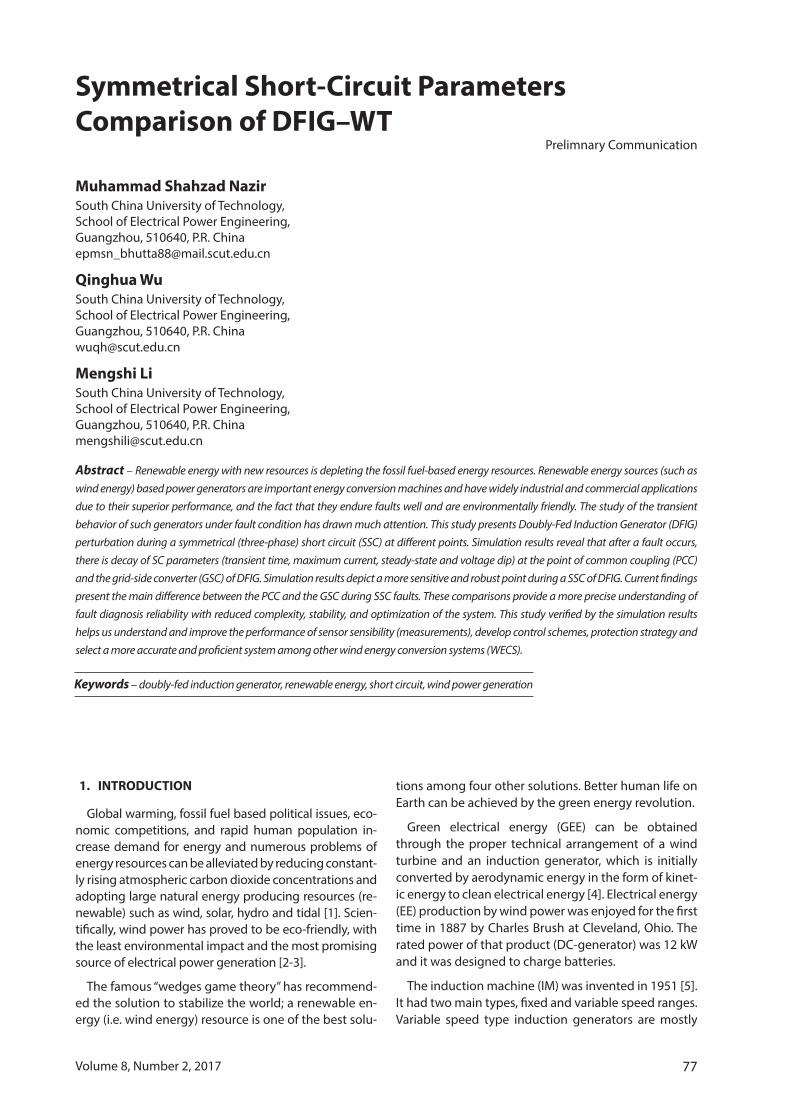
The main parts of the DFIG-WT system are shown in Fig. 1 and the DFIG parameters are listed in Ap-pendix A. The wind turbine system is a combination of mechanical and electrical components, the DFIG generator, the rotor-side converter (RSC), the DC link, the grid-side converter (GSC and its filter), the control system, both fault points, the transformer and load. Controlling parts are modified according to the load or required system.
Fig. 1. Schematic diagram of the DFIG-based wind turbine
Generally, advantages of the DFIG-WT system can be summarized as follows [24-25]:
• Economical inverter/converter, because of the converter and filter size compared to other ASGs (a synchronous generator) [24].
• It has the ability to work in a wide range of wind speed.
• A low rating of converters improves system effi-ciency; a low rating makes the system less loss-prone.
• Power factor control can be implemented at lower cost.
• It has four quadrant converters in the rotor cir-cuit that enable control of active and reactive power of the generator.
• By improving the efficiency of energy transferred from wind energy, the DFIG can even generate twice its own rating power at the slip value of s = -1 [26].
The DFIG has better performance during a voltage dip, transient time and other perturbation situation than other ASGs systems. All aforementioned proper-ties make the DFIG more reliable and a better choice for WECS. The DFIG has two main operation modes, i.e. sub-synchronous and super-synchronous [27].
A. Super-Synchronous
When the generator’s rotor rotates at a speed greater than its synchronous speed, this operation is called su-per-synchronous. The slip becomes negative and both the rotor and the stator deliver power to the grid.
B. Sub-Synchronous
When the generator operates at its synchronous speed, this is called sub-synchronous mode. Obviously, the slip operates in positive mode and a stator wind-ing delivers power to both the grid and a rotor winding. This mode does not exceed the rated power compared to the other super-synchronous mode. This mode has a smaller rotational speed.
3.1 MaThEMaTICaL MoDEL oF DFIG
For mathematical modeling of the DFIG, the stator, the rotor and both fluxes can be represented as [12]:
(2)
(3)
(4)
(5)
The rotor winding induced EMF in terms of rotor volt-age, so the rotor side current can be expressed as:
(6)
The equation above induces the EMF based on stator flux dynamics; it can be induced in the stator reference frame or in the rotor reference frame. The equivalent cir-cuit of the DFIG in Fig. 2 represents its frame references.
(7)
Here ms
s
LcL
= is the coupling factor of stator-side converters.
Fig. 2 represents the external supply of the DFIG by RSC; the rotor-side equivalent circuit of the generator is developed by using Equation 6.

80 International Journal of Electrical and Computer Engineering Systems
Fig. 2. Stator reference frame equivalent circuit of the DFIG
Stator voltage oriented (SVO) references are ex-pressed at the stator side actively and reactive power is delivered by the DFIG. Fig. 3 represents the rotor equivalent circuit.
Fig. 3. Rotor reference frame equivalent circuit of the DFIG
Equations 8 and 9 (A, B) represents the stator active and reactive power. Modeling of the DFIG is described in [28]. The DFIG system has been modeled with the help of the PSCAD/ EMTDC platform.
4. SIMULATION STUDIES AND DISCUSSION
It is important for advanced protection, control and compatible schemes to provide smooth operation of the dependent system. It is also necessary the system is understood well before any control or protection scheme is applied. This section of our paper presents simulation results generated by PSCAD/ EMTDC. The simulation system is a single-machine infinite bus sys-tem. The parameters of the DFIG-WT and the transform-er are standard and they are extracted from the PSCAD library. The values of parameters are developed and set in per-unit with the reference of the rated power and voltage. Considering the perturbation conditions of the DFIG-WT, the proposed short circuit scheme has been applied at different points of the DFIG-based wind energy system. To maintain smooth operation and reliability with grid power quality, an SSC fault was applied at the GSC/machine side and the PCC/high-voltage side of the transformer. What is most important for the implementation of the technical standard is to meet the grid code requirements. There are two types of grid code requirements, i.e. dynamic and static re-quirements. A static requirement contains steady-state behavior and power flow at the PCC. The steady-state
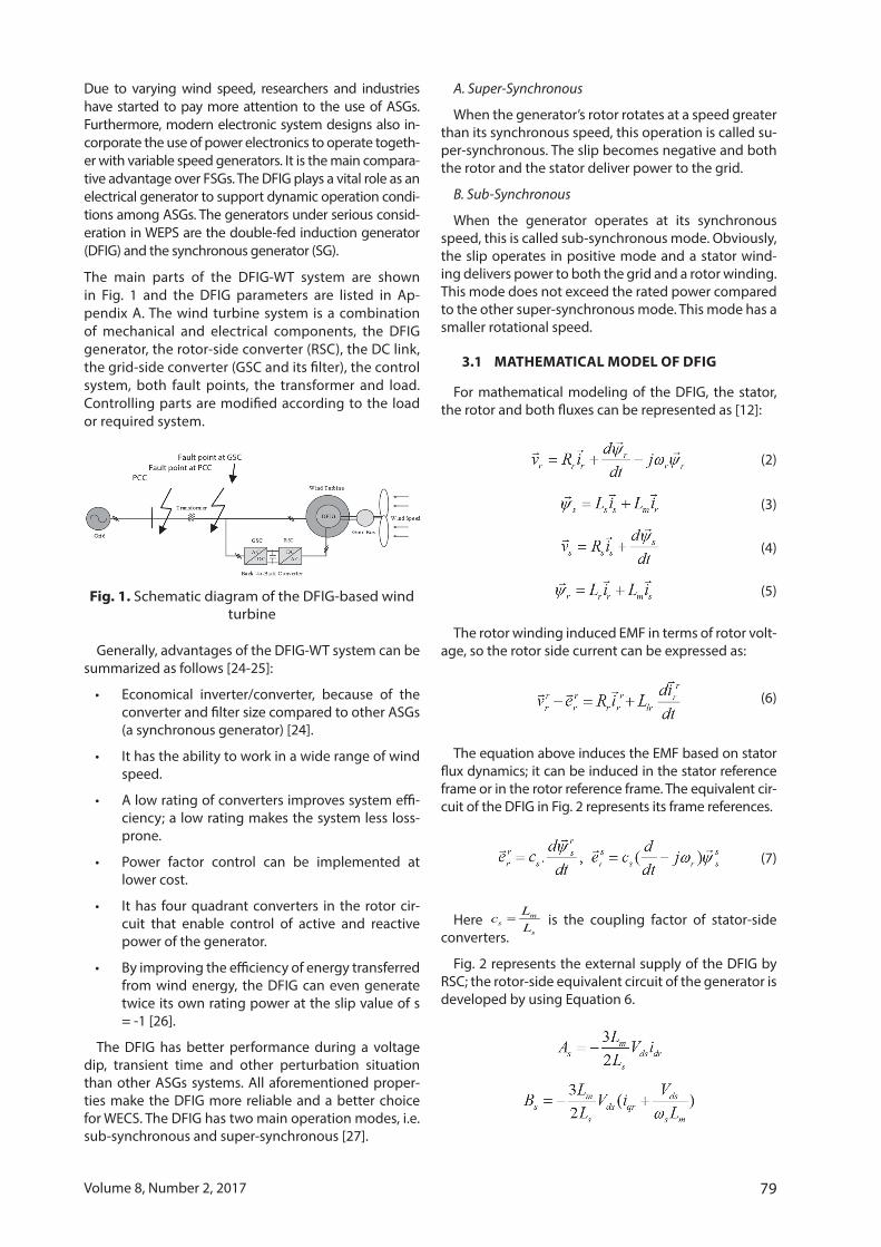
behavior is observed in Figures 4(c) and 5(c). Hence dynamic grid codes look up to the desired responses of the induction generator during grid perturbation. These requirements cover the frequency and voltage, grid supporting capability, power factor regulation, fault ride-through (FRT) or low-voltage ride-through (LVRT) capability operating range simultaneously.
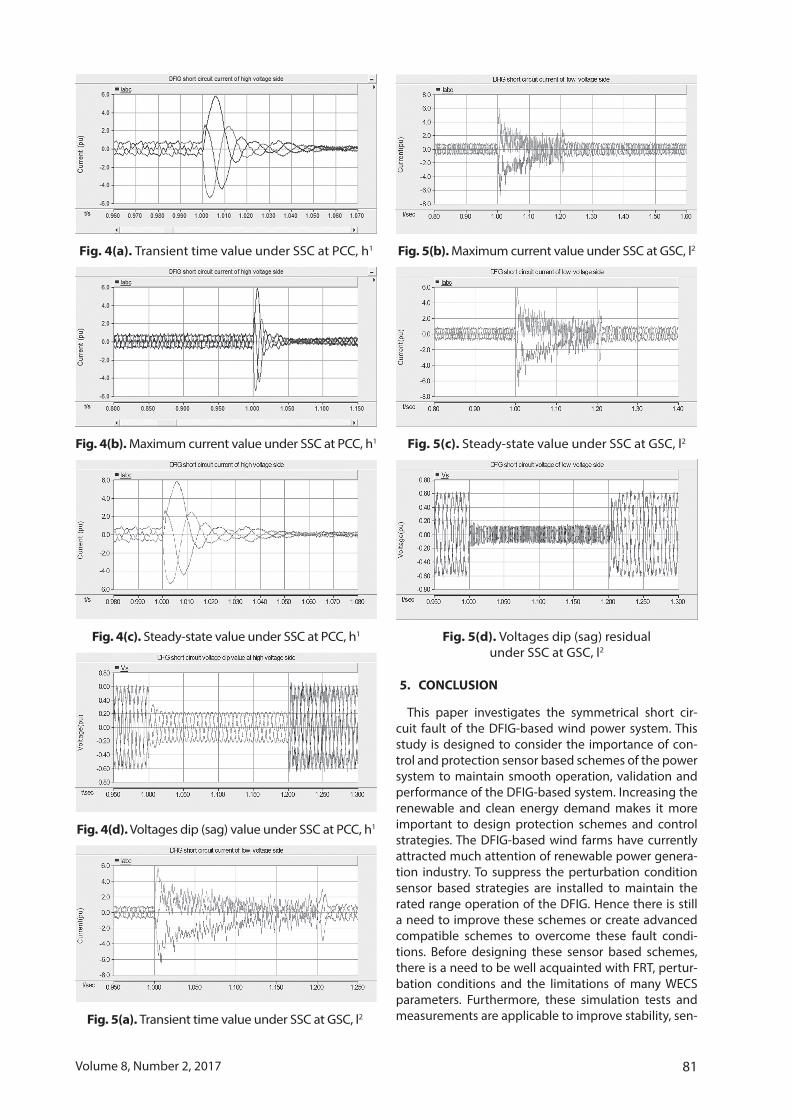
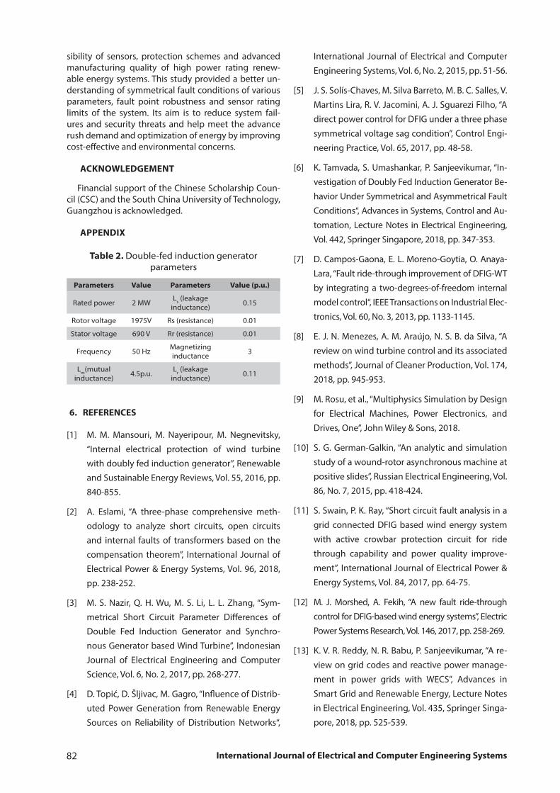
Therefore, the short circuit (SC) fault is applied at dif-ferent points to observe the transient time, maximum current, steady-state and voltage dip (sag) or fault ride-though (FRT) values. Simulation results were compared and it was concluded that a more sensitive and weak point was under the SSC. The SSC was applied at 1-1.20 s with the resistance range of 0.02 Ω. The fault trigger-ing time was kept the same, i.e. two seconds (1-1.20 s) at the PCC and the GSC to collect simulation results. Pa-rameter differences under the SC process is presented in plotted results and in Table 1. Simulation results dur-ing the SSC are depicted in Figures 4 and 5 and Table 1. A SSC applied at the PCC or a high voltage side bus transformer of the DFIG-WT. The value of SC resistance is 0.2 Ω. Transient time’s simulation value during per-turbation is depicted in Fig. 4(a). The transient time val-ue given in Table 1 is 1.015 s (1-1.015 s), while the low voltage side or the GSC value given in Fig. 5(a) is 1.21 s (1-1.21 s). The GSC or low voltage side transient time is 0.1 times greater than the one of the PCC or a high voltage side. The maximum current value depicted in Figures 4(b) and 5(b) shows a smaller difference on both sides of the DFIG-WT, i.e. 5.76 p.u and 5.75 p.u. The steady-state of the SSC shows the difference of 0.34 p.u and 0.53 p.u at the PCC and the GSC, which is presented in Figures 4(c) and 5(c), respectively. The PCC or a high voltage side has 0.19 times greater difference than the GSC or a low voltage side. Figures 4(d) and 5(d) illus-trate the voltage sag value. The SSC of the PCC value is 0.58 p.u-0.21 p.u., while GSC has 0.58 p.u-0.11 p.u. The voltage dipped value difference is 0.50 times, manifest-ing a more sensitive side of the DFIG-WT. The numerical SSC resulting values numbered in Table 1 and Table 2 depict the DFIG parameters.
In conclusion, this study is available for further SSC stud-ies and other perturbation conditions analysis. Transient time (0.19 times), maximum current, steady-state cur-rent value (0.19 times) and the voltage dip (sag) depicted the 0.50 times difference between the PCC and the GSC. These simulation results can be implemented further to build a protection or control strategy for smooth power generation during perturbation, respectively.
Table 1. DFIG-WT SSC simulation results
Generator Transient time (sec)
Maximum current (p.u.)
Steady-state current
(p.u.)
Voltage dip/sag
(p.u.)
DFIG PCC, h1 1.015 5.76 0.34 0.58-0.21
DFIG GSC, l2 1.21 5.75 0.53 0.58-0.11
Difference (%) 19 0.01 19 50
h1 and l2 represent the high and the low voltage side, respectively.
81Volume 8, Number 2, 2017
Fig. 4(a). Transient time value under SSC at PCC, h1
Fig. 4(b). Maximum current value under SSC at PCC, h1
Fig. 4(c). Steady-state value under SSC at PCC, h1
Fig. 4(d). Voltages dip (sag) value under SSC at PCC, h1
Fig. 5(a). Transient time value under SSC at GSC, l2
Fig. 5(b). Maximum current value under SSC at GSC, l2
Fig. 5(c). Steady-state value under SSC at GSC, l2
Fig. 5(d). Voltages dip (sag) residual under SSC at GSC, l2
5. CONCLUSION
This paper investigates the symmetrical short cir-cuit fault of the DFIG-based wind power system. This study is designed to consider the importance of con-trol and protection sensor based schemes of the power system to maintain smooth operation, validation and performance of the DFIG-based system. Increasing the renewable and clean energy demand makes it more important to design protection schemes and control strategies. The DFIG-based wind farms have currently attracted much attention of renewable power genera-tion industry. To suppress the perturbation condition sensor based strategies are installed to maintain the rated range operation of the DFIG. Hence there is still a need to improve these schemes or create advanced compatible schemes to overcome these fault condi-tions. Before designing these sensor based schemes, there is a need to be well acquainted with FRT, pertur-bation conditions and the limitations of many WECS parameters. Furthermore, these simulation tests and measurements are applicable to improve stability, sen-
82 International Journal of Electrical and Computer Engineering Systems
sibility of sensors, protection schemes and advanced manufacturing quality of high power rating renew-able energy systems. This study provided a better un-derstanding of symmetrical fault conditions of various parameters, fault point robustness and sensor rating limits of the system. Its aim is to reduce system fail-ures and security threats and help meet the advance rush demand and optimization of energy by improving cost-effective and environmental concerns.
aCKNoWLEDGEMENT
Financial support of the Chinese Scholarship Coun-cil (CSC) and the South China University of Technology, Guangzhou is acknowledged.
aPPENDIX
Parameters Value Parameters Value (p.u.)
Rated power 2 MW Ls (leakage inductance) 0.15
Rotor voltage 1975V Rs (resistance) 0.01
Stator voltage 690 V Rr (resistance) 0.01
Frequency 50 Hz Magnetizing inductance 3
Lm(mutual inductance) 4.5p.u. Lr (leakage
inductance) 0.11
6. REFERENCES
[1] M. M. Mansouri, M. Nayeripour, M. Negnevitsky,
“Internal electrical protection of wind turbine
with doubly fed induction generator”, Renewable
and Sustainable Energy Reviews, Vol. 55, 2016, pp.
840-855.
[2] A. Eslami, “A three-phase comprehensive meth-
odology to analyze short circuits, open circuits
and internal faults of transformers based on the
compensation theorem”, International Journal of
Electrical Power & Energy Systems, Vol. 96, 2018,
pp. 238-252.
[3] M. S. Nazir, Q. H. Wu, M. S. Li, L. L. Zhang, “Sym-
metrical Short Circuit Parameter Differences of
Double Fed Induction Generator and Synchro-
nous Generator based Wind Turbine”, Indonesian
Journal of Electrical Engineering and Computer
Science, Vol. 6, No. 2, 2017, pp. 268-277.
[4] D. Topić, D. Šljivac, M. Gagro, “Influence of Distrib-
uted Power Generation from Renewable Energy
Sources on Reliability of Distribution Networks“,
Table 2. Double-fed induction generator parameters
International Journal of Electrical and Computer
Engineering Systems, Vol. 6, No. 2, 2015, pp. 51-56.
[5] J. S. Solís-Chaves, M. Silva Barreto, M. B. C. Salles, V.
Martins Lira, R. V. Jacomini, A. J. Sguarezi Filho, “A
direct power control for DFIG under a three phase
symmetrical voltage sag condition”, Control Engi-
neering Practice, Vol. 65, 2017, pp. 48-58.
[6] K. Tamvada, S. Umashankar, P. Sanjeevikumar, “In-
vestigation of Doubly Fed Induction Generator Be-
havior Under Symmetrical and Asymmetrical Fault
Conditions“, Advances in Systems, Control and Au-
tomation, Lecture Notes in Electrical Engineering,
Vol. 442, Springer Singapore, 2018, pp. 347-353.
[7] D. Campos-Gaona, E. L. Moreno-Goytia, O. Anaya-
Lara, “Fault ride-through improvement of DFIG-WT
by integrating a two-degrees-of-freedom internal
model control“, IEEE Transactions on Industrial Elec-
tronics, Vol. 60, No. 3, 2013, pp. 1133-1145.
[8] E. J. N. Menezes, A. M. Araújo, N. S. B. da Silva, “A
review on wind turbine control and its associated
methods”, Journal of Cleaner Production, Vol. 174,
2018, pp. 945-953.
[9] M. Rosu, et al., “Multiphysics Simulation by Design
for Electrical Machines, Power Electronics, and
Drives, One”, John Wiley & Sons, 2018.
[10] S. G. German-Galkin, “An analytic and simulation
study of a wound-rotor asynchronous machine at
positive slides”, Russian Electrical Engineering, Vol.
86, No. 7, 2015, pp. 418-424.
[11] S. Swain, P. K. Ray, “Short circuit fault analysis in a
grid connected DFIG based wind energy system
with active crowbar protection circuit for ride
through capability and power quality improve-
ment”, International Journal of Electrical Power &
Energy Systems, Vol. 84, 2017, pp. 64-75.
[12] M. J. Morshed, A. Fekih, “A new fault ride-through
control for DFIG-based wind energy systems”, Electric
Power Systems Research, Vol. 146, 2017, pp. 258-269.
[13] K. V. R. Reddy, N. R. Babu, P. Sanjeevikumar, “A re-
view on grid codes and reactive power manage-
ment in power grids with WECS”, Advances in
Smart Grid and Renewable Energy, Lecture Notes
in Electrical Engineering, Vol. 435, Springer Singa-
pore, 2018, pp. 525-539.
83Volume 8, Number 2, 2017
[14] G. P. Prajapat, N. Senroy, I. N. Kar, “Wind Turbine Structural Modeling Consideration for Dynamic Studies of DFIG based System”, IEEE Transactions on Sustainable Energy, Vol. 8, No. 4, 2017, pp. 1463-1472.
[15] A. Dejanović, M. Babić, M. Tomašević, “Measur-ing Electric Power Quality of Renewable Energy Sources”, International Journal of Electrical and Computer Engineering Systems, Vol. 2, No. 2, 2011, pp. 81-88.
[16] M. Hossain, H. Ali, “Asymmetric fault ride through capability enhancement of DFIG based variable speed wind generator by DC resistive fault cur-rent limiter”, Proceedings of the Transmission and Distribution Conference and Exposition, Dallas, Texas, USA, 3-5 May 2016, pp. 1-5.
[17] M. E. Hossain, T. E. Wyatt, “Comparison among Se-ries Compensating devices for Transient Stability Enhancement of DFIG Based Variable speed Wind Generator”, Proceedings of the Transmission and Distribution Conference and Exposition, Dallas, Texas, USA, 3-5 May 2016, Poster.
[18] F. Blaabjerg, M. Liserre K. Ma, “Power electronics converters for wind turbine systems”, IEEE Trans-actions on Industry Applications, Vol. 48, No. 2, 2012, pp. 708-719.
[19] E. Dupont R. Koppelaar, H. Jeanmart, “Global avail-able wind energy with physical and energy return on investment constraints”, Applied Energy, Vol. 209, 2018, pp. 322-338.
[20] A. Gupta, S. N. Singh, D. K. Khatod, “Modeling and simulation of doubly fed induction generator cou-pled with wind turbine - an overview”, Journal of Engineering, Computers & Applied Sciences, Vol. 2, No. 8, 2013, pp. 45-54.
[21] P. M. Anderson, A. Bose, “Stability simulation of wind turbine systems”, IEEE Transactions on Power Appa-ratus and Systems, Vol. 12, 1983, pp. 3791-3795.
[22] J. Lopez, E. Gubia, P. Sanchis, X. Roboam, L. Mar-royo, “Wind turbines based on doubly fed induc-tion generator under asymmetrical voltage dips”, IEEE Transactions on Energy Conversion, Vol. 23, No. 1, 2008, pp. 321-330.
[23] J. J. Justo, F. Mwasilu J. W. Jung, “Effective protec-tion for doubly fed induction generator-based wind turbines under three-phase fault condi-tions”, Electrical Engineering, 2017, pp. 1-14.
[24] J. Morren, S. W. H. De Haan, “Ridethrough of wind turbines with doubly-fed induction generator during a voltage dip”, IEEE Transactions on Energy Conversion, Vol. 20, No. 2, 2005, pp. 435-441.
[25] M. Gholizadeh, A. Oraee, S. Tohidi, H. Oraee, R. A. McMahon, “An analytical study for low voltage ride through of the brushless doubly-fed induc-tion generator during asymmetrical voltage dips”, Renewable Energy, Vol. 115, 2018, pp. 64-75.
[26] H. A. Mohammadpour, E. Santi, “Modeling and control of gate-controlled series capacitor inter-faced with a DFIG-based wind farm”, IEEE Transac-tions on Industrial Electronics, Vol. 62, No. 2, 2015, pp. 1022-1033.
[27] J. Andreu, J. M. De Diego, I. M. de Alegría, I. Kortabar-ria, J. L. Martin, S. Ceballos, “New protection circuit for high-speed switching and start-up of a practical matrix converter”, IEEE Transactions on Industrial Electronics, Vol. 55, No. 8, 2008, pp. 3100-3114.
[28] M. Zhao, X. Yuan, J. Hu, “Modeling of DFIG Wind Turbine Based on Internal Voltage Motion Equa-tion in Power Systems Phase-Amplitude Dynam-ics Analysis”, IEEE Transactions on Power Systems, 2017 (in press).