improvement dfig behaviour against symmetrical short ... · improvement dfig behaviour against...
TRANSCRIPT
Available onlinewww.ejaet.com
European Journal of Advances in Engineering and Technology, 2015, 2(9): 1-7
Research Article ISSN: 2394 - 658X
1
Improvement DFIG Behaviour against Symmetrical Short Circuit Fault by Superconducting Current Limiter
Mohammad Yousefikia1, Ehsan Gharibreza2 and Moslem Baledi3
1Khorramshahr University of Marine Science & Technology, Khorramshahr, Iran 2Khuzestan Regional Electric Co, Ahvaz, Iran
3Ahvaz Electrical Power Distribution Co, Ahvaz, Iran [email protected]
_____________________________________________________________________________________________
ABSTRACT
With the increase of DG in distribution network, good management of these systems is faced with new challenges. One of the most DG sources is doubly-fed induction generator (DFIG). By connecting them, the short circuit level (SCL) of network has been increased and it may be exceeded over the capacity of equipment such as breaker. So reliability will reduce in compare with the absence of DFIG in the network. In this paper, the superconducting fault current limiter (SC-FCL) has been used as a new technology for reducing large fault currents, increased security, reliability and stability of DFIG transient. Dynamic Model of SC-FCL is simulated with regard to all basic details including control algorithms, sequence of operation and error detection techniques in (PSCAD/EMTDC) software. Different cases with DFIG connected to the network and the impact of SC-FCL on it have been investigated. The result show that SC-FCL limits the fault current contribution of DFIG to a certain amount (that is improve the security and transient stability of DFIG during short circuit in the network) and operates as a compensator in such situation. Voltage sag as a very important index in power quality improves at the point of DFIG connection to grid.
Key words: SC-FCL, DFIG, Fault Current, DFIG Security, Voltage Sag _____________________________________________________________________________________
INTRODUCTION
Due to the increases in energy demand and environmental changes, the capacity of DG sources that mainly connected to the distribution networks, is developing [1]. Wind-turbine based generation system (WTGS) represents one of the renewable energy sources. Due to the rapid development and increasing the capacity of the resource, the short-circuit current level increases during the fault occurrence [1-3]. That would be creating a negative impact on the basic Parameters of power system (such as transient stability) at the point of their connection to the network. Moreover, the performance of protective equipment such as circuit breakers may also be affected. In such circumstances, the capacity of short circuit protective equipment in the network, should be fit proportional to new short circuit level or replaced with new equipment. One of the most fault current control methods is network topology reconfiguration and break system into several smaller parts. This method is affected system characteristic and stability. Another way to decrease fault current is usage of fault current limiter (FCL). This device is consist of two types; resistive and inductive. Resistive type is simpler and more compact from the point of structural view. This kind is more considered because of its affectivity, especially after rapid development in producing second generation superconductor windings [3-11]. It is possible to reach more benefits by placing SC-FCL in proper location of network. Some of these advantages are as follows [1-2]:
• Reduce fault current to a tolerable level for instrument. • Avoid replacing of existing breakers with higher cutting capacity ones. • Possibility of transformer installation with a low impedance that leads to lower investment cost. • Prevent of network bus splitting. • Increase system stability.
One solution to reduce increased short-circuit current in network with DFIG during the fault is use of SC-FCL. This device has no losses in normal operation and could be active at the first cycle of fault current rapidly and prevented the increase in short-circuit current of the network.This will be subject to improve system security and

Yousefikia et al ______________________________________________________________________________
transient stability due to the current limiting. So this paper presents an accurate dynamic model for superconducting limiter in order to reduce short
Basic parameters that effected SC-FCL characteristics are as follow: Fault current (Ilim), time duration of fault (related together in 1 to 3 [5]:
I
VR =
lim
0
tI =lim
o C
IV =1
Since the most high short-circuit current is due to 3determined under such situation. In a balanced system like as index A, resistance value for a 3is calculated as:
FCLSCZ −
Dynamic model of SC-FCL with consideration of some basic indices such as control operation algorithm, activation time and fault detection techniques has been simulated in PSCAD/EMTDC. So this model represents specifications and real behavior of SCdegree as below [12]:
FCLSCR −
That RQ is SC max resistance in quenching mode and B is temperature adaptive factor.
In this paper, a variable resistor is used for the modeling of superconducting windings. In large fault currents, the resistance of SC-FCL has been increased. The variable resistor is very small (about 0.01 ohms) in normal operation of network and begin to rise with a certain slope (1the various intervals have been shown in fig (1
The sequence of SC-FCL function at various time intervals can be expressed as follows:1. At t < t1 Steady state line to line current passes of Route 1 and SC2. At t=t1 fault is detected and control system activates the switch at 1
opened , fault current passes of Route 2 a3. At t3=t2+2 ms, the resistance of SC4. At t4, when the fault is cleared, control circuit activates the switch and resistance value starts to reduce with a
high gradient. 5. At t5, variable resistance reaches to its initial value (R
Fig.1 SC_FCL simple power circuit diagram
Euro. J. Adv. Engg. Tech., 201______________________________________________________________________________
2
transient stability due to the current limiting. So this paper presents an accurate dynamic model for superconducting limiter in order to reduce short-circuits current of DFIG and improves its behavior.
DYNAMIC MODELING OF SC-FCL
FCL characteristics are as follow: ), time duration of fault (Δt), tolerable temperature of superconductor windings. All of these are
tw
lρ=lim
0
t
tp
P
Cwt
∆∆
...
Tp
o
C
VI
∆..lim
circuit current is due to 3-phase symmetrical fault, so the resistance of SCdetermined under such situation. In a balanced system like as index A, resistance value for a 3
sysb
bFCL ZZ
Z
+−=
2
FCL with consideration of some basic indices such as control operation algorithm, activation time and fault detection techniques has been simulated in PSCAD/EMTDC. So this model represents
behavior of SC-FCL at the fault stages. Resistance of SC-FCL is function of temperature
)1( )( 0TTBQFCL
FCLSCeR −−−×= is SC max resistance in quenching mode and B is temperature adaptive factor.
istor is used for the modeling of superconducting windings. In large fault currents, the FCL has been increased. The variable resistor is very small (about 0.01 ohms) in normal operation
of network and begin to rise with a certain slope (100 ms / ohms) during the fault. Model and Timing diagram of the various intervals have been shown in fig (1-2) respectively.
FCL function at various time intervals can be expressed as follows: Steady state line to line current passes of Route 1 and SC-FCL resistance value is almost zero.
fault is detected and control system activates the switch at 1-2 ms interval, at the moment of topened , fault current passes of Route 2 and variable resistance value is began to rise.
the resistance of SC-FCL, began to rise until it reaches the maximum value., when the fault is cleared, control circuit activates the switch and resistance value starts to reduce with a
, variable resistance reaches to its initial value (Rmin)
SC_FCL simple power circuit diagram Fig.2Performance diagram of SC
Euro. J. Adv. Engg. Tech., 2015, 2(9):1-7 ______________________________________________________________________________
transient stability due to the current limiting. So this paper presents an accurate dynamic model for FIG and improves its behavior.
), tolerable temperature of superconductor windings. All of these are
(1)
(2)
(3)
phase symmetrical fault, so the resistance of SC-FCL is determined under such situation. In a balanced system like as index A, resistance value for a 3-phase fault in bus k
(4)
FCL with consideration of some basic indices such as control operation algorithm, activation time and fault detection techniques has been simulated in PSCAD/EMTDC. So this model represents
FCL is function of temperature
(5)
istor is used for the modeling of superconducting windings. In large fault currents, the FCL has been increased. The variable resistor is very small (about 0.01 ohms) in normal operation
00 ms / ohms) during the fault. Model and Timing diagram of
FCL resistance value is almost zero.
2 ms interval, at the moment of t2 switch is nd variable resistance value is began to rise.
FCL, began to rise until it reaches the maximum value. , when the fault is cleared, control circuit activates the switch and resistance value starts to reduce with a
erformance diagram of SC-FCL at various time intervals
Yousefikia et al ______________________________________________________________________________
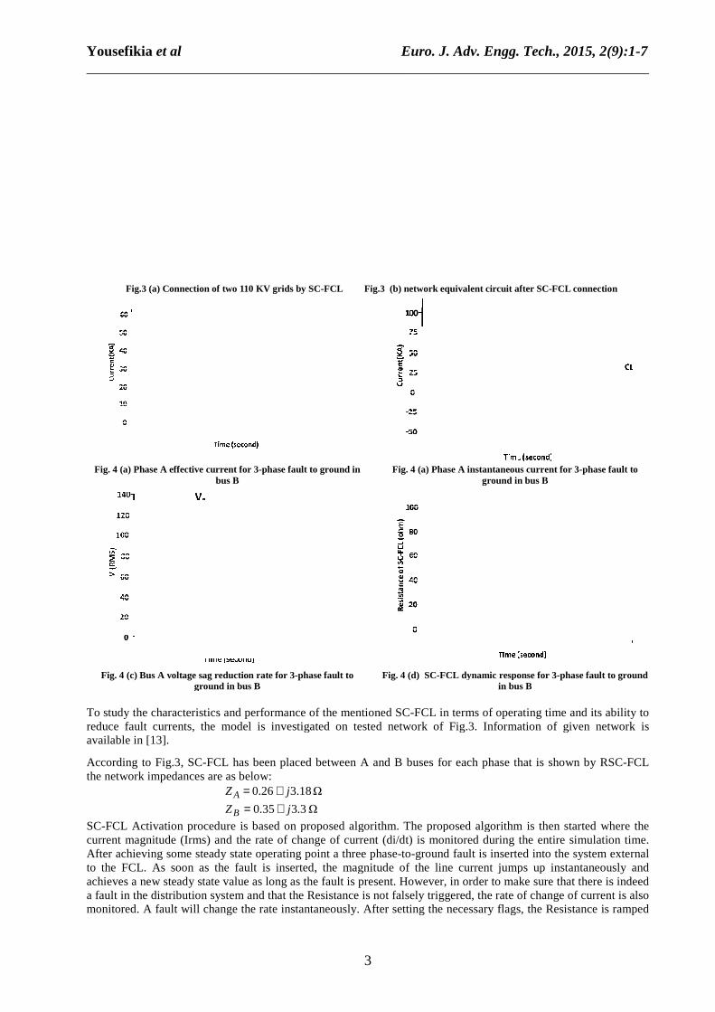
Fig.3 (a) Connection of two 110 KV grids by SC
Fig. 4 (a) Phase A effective current for 3bus B
Fig. 4 (c) Bus A voltage sag reduction rate for 3ground in bus B
To study the characteristics and performance of the mentioned SCreduce fault currents, the model is investigated on tested network of Fig.3. Information of given network is available in [13].
According to Fig.3, SC-FCL has been placed between A and B buses for each phase that is shown by RSCthe network impedances are as below:
.0Z A =0ZB =
SC-FCL Activation procedure is based on proposed algorithm. The proposed algorithm is then started where the current magnitude (Irms) and the rate of change of current (After achieving some steady state operating point a three phaseto the FCL. As soon as the fault is inserted, the magnitude of the line current jumps up instantaneouslachieves a new steady state value as long as the fault is present. However, in order to make sure that there is indeed a fault in the distribution system and that the Resistance is not falsely triggered, the rate of change of current is also monitored. A fault will change the rate instantaneously. After setting the necessary flags, the Resistance is ramped
Euro. J. Adv. Engg. Tech., 201______________________________________________________________________________
3
Connection of two 110 KV grids by SC-FCL Fig.3 (b) network equivalent circuit after SC
-phase fault to ground in Fig. 4 (a) Phase A instantaneous current for 3ground in bus B
reduction rate for 3-phase fault to
ground in bus B Fig. 4 (d) SC-FCL dynamic response for 3
in bus B
To study the characteristics and performance of the mentioned SC-FCL in terms of operating time and its ability to urrents, the model is investigated on tested network of Fig.3. Information of given network is
FCL has been placed between A and B buses for each phase that is shown by RSCbelow:
18.326. j+ Ω 3.335.0 j+ Ω
FCL Activation procedure is based on proposed algorithm. The proposed algorithm is then started where the current magnitude (Irms) and the rate of change of current (di/dt) is monitored during the entire simulation time. After achieving some steady state operating point a three phase-to-ground fault is inserted into the system external to the FCL. As soon as the fault is inserted, the magnitude of the line current jumps up instantaneouslachieves a new steady state value as long as the fault is present. However, in order to make sure that there is indeed a fault in the distribution system and that the Resistance is not falsely triggered, the rate of change of current is also
d. A fault will change the rate instantaneously. After setting the necessary flags, the Resistance is ramped
Euro. J. Adv. Engg. Tech., 2015, 2(9):1-7 ______________________________________________________________________________
network equivalent circuit after SC-FCL connection
hase A instantaneous current for 3-phase fault to
ground in bus B
FCL dynamic response for 3-phase fault to ground in bus B
FCL in terms of operating time and its ability to urrents, the model is investigated on tested network of Fig.3. Information of given network is
FCL has been placed between A and B buses for each phase that is shown by RSC-FCL
FCL Activation procedure is based on proposed algorithm. The proposed algorithm is then started where the during the entire simulation time.
ground fault is inserted into the system external to the FCL. As soon as the fault is inserted, the magnitude of the line current jumps up instantaneously and achieves a new steady state value as long as the fault is present. However, in order to make sure that there is indeed a fault in the distribution system and that the Resistance is not falsely triggered, the rate of change of current is also
d. A fault will change the rate instantaneously. After setting the necessary flags, the Resistance is ramped
Yousefikia et al ______________________________________________________________________________
up at a rate Rslope(Ω). As long as the fault is present, the Resistance will keep increasing till a maximum value Rmax(Ω). After the fault is cleared the Resistance will be ramped down to the initial impedance. This cycle takes place whenever there is a fault. Results show that SCpercent when a 3-phase symmetrical fault is in bus B (Fig. 4Aamplifier (booster) so that voltage profile in bus A is improved, during 3device acts as a stabilizer in order to recovery transient stability and voltage stability during threduces voltage sag (important index of power quality) in bus A.
Among the different types of production systems based on wind energy, doublycommonly used because of its unique features. frequency converter. The stator and the rotor are connected to the network directly and via a converter respectively. The major property of DFIG is producing of power with constant frequencyvery important in wind energy unit commitment. It is also possible to recycle the rotor power at the speeds higher than synchronous speed and inject it to the network in such system. Power direction in rotor windings is bilateraand in stator ones is toward network. To achieve the above circumstances a birotor. Power of applied transducer is a fraction of the total machine power which is an advantage. The original configuration of doubly-fed wind turbine system is shown in Fig.5.
In this paper proposed model of [6], is used for modelling of DFIG. Mechanical power from wind energy can be calculated according to Equation [6
wtP2
1=
The considered model of the DFIG, including turbines, gearboxes, shafts and other mechanical parts of the wind turbine, which is mostly expressed with a second
wtTTmec
Tmec =
mecTTe
In the above equations, (Twt) is the mechanical torque of wind turbine rotor shaft, (Tgenerator shaft, (Te) is electric generator torque, Dmechanical connections respectively.
SIMULATION AND NUMERICAL RESULTS
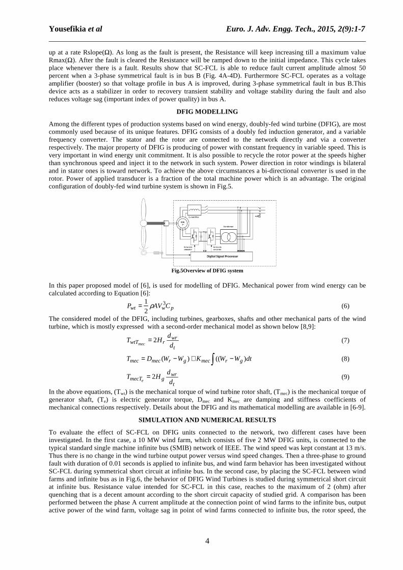
To evaluate the effect of SC-FCL on DFIG units connected to the network, two different cases have been investigated. In the first case, a 10 MW wind farm, which consists of five 2 MW DFIG units, is connected to the typical standard single machine infinite Thus there is no change in the wind turbine output power versus wind speed changes. Then a threefault with duration of 0.01 seconds is applied to infinite bus, and winSC-FCL during symmetrical short circuit at infinite bus. In the second case, by placing the SCfarms and infinite bus as in Fig.6, the behavior of DFIG Wind Turbines is studied during symmetricat infinite bus. Resistance value intended for SCquenching that is a decent amount according to the short circuit capacity of studied grid. A comparison has been performed between the phase A current amplitude at the connection point of wind farms to the infinite bus, output active power of the wind farm, voltage sag in point of wind farms connected to infinite bus, the rotor speed, the
Euro. J. Adv. Engg. Tech., 201______________________________________________________________________________
4
). As long as the fault is present, the Resistance will keep increasing till a maximum value ed the Resistance will be ramped down to the initial impedance. This cycle takes
place whenever there is a fault. Results show that SC-FCL is able to reduce fault current amplitude almost 50 phase symmetrical fault is in bus B (Fig. 4A-4D). Furthermore SC-
amplifier (booster) so that voltage profile in bus A is improved, during 3-phase symmetrical fault in bus B.This device acts as a stabilizer in order to recovery transient stability and voltage stability during threduces voltage sag (important index of power quality) in bus A.
DFIG MODELLING
Among the different types of production systems based on wind energy, doubly-fed wind turbine (DFIG), are most commonly used because of its unique features. DFIG consists of a doubly fed induction generator, and a variable frequency converter. The stator and the rotor are connected to the network directly and via a converter respectively. The major property of DFIG is producing of power with constant frequencyvery important in wind energy unit commitment. It is also possible to recycle the rotor power at the speeds higher than synchronous speed and inject it to the network in such system. Power direction in rotor windings is bilateraand in stator ones is toward network. To achieve the above circumstances a bi-directional converter is used in the rotor. Power of applied transducer is a fraction of the total machine power which is an advantage. The original
wind turbine system is shown in Fig.5.
Fig.5Overview of DFIG system
In this paper proposed model of [6], is used for modelling of DFIG. Mechanical power from wind energy can be
6]:
pwCAV 3
2
1 ρ considered model of the DFIG, including turbines, gearboxes, shafts and other mechanical parts of the wind
turbine, which is mostly expressed with a second-order mechanical model as shown below [8,9]:
t
wrr d
dH2=
dtWWKWWD grmecgrmec )(()( −+− ∫
t
wrg d
dH2=
mechanical torque of wind turbine rotor shaft, (Tmec) is the mechanical torque of ) is electric generator torque, Dmec and Kmec are damping and stiffness coefficients of
mechanical connections respectively. Details about the DFIG and its mathematical modelling are
SIMULATION AND NUMERICAL RESULTS
FCL on DFIG units connected to the network, two different cases have been investigated. In the first case, a 10 MW wind farm, which consists of five 2 MW DFIG units, is connected to the typical standard single machine infinite bus (SMIB) network of IEEE. The wind speed was kept constant at 13 m/s. Thus there is no change in the wind turbine output power versus wind speed changes. Then a threefault with duration of 0.01 seconds is applied to infinite bus, and wind farm behavior has been investigated without
FCL during symmetrical short circuit at infinite bus. In the second case, by placing the SCfarms and infinite bus as in Fig.6, the behavior of DFIG Wind Turbines is studied during symmetricat infinite bus. Resistance value intended for SC-FCL in this case, reaches to the maximum of 2 (ohm) after quenching that is a decent amount according to the short circuit capacity of studied grid. A comparison has been
the phase A current amplitude at the connection point of wind farms to the infinite bus, output active power of the wind farm, voltage sag in point of wind farms connected to infinite bus, the rotor speed, the
Euro. J. Adv. Engg. Tech., 2015, 2(9):1-7 ______________________________________________________________________________
). As long as the fault is present, the Resistance will keep increasing till a maximum value ed the Resistance will be ramped down to the initial impedance. This cycle takes
FCL is able to reduce fault current amplitude almost 50 -FCL operates as a voltage
phase symmetrical fault in bus B.This device acts as a stabilizer in order to recovery transient stability and voltage stability during the fault and also
fed wind turbine (DFIG), are most DFIG consists of a doubly fed induction generator, and a variable
frequency converter. The stator and the rotor are connected to the network directly and via a converter respectively. The major property of DFIG is producing of power with constant frequency in variable speed. This is very important in wind energy unit commitment. It is also possible to recycle the rotor power at the speeds higher than synchronous speed and inject it to the network in such system. Power direction in rotor windings is bilateral
directional converter is used in the rotor. Power of applied transducer is a fraction of the total machine power which is an advantage. The original
In this paper proposed model of [6], is used for modelling of DFIG. Mechanical power from wind energy can be
(6)
considered model of the DFIG, including turbines, gearboxes, shafts and other mechanical parts of the wind order mechanical model as shown below [8,9]:
(7)
(8)
(9)
) is the mechanical torque of are damping and stiffness coefficients of
Details about the DFIG and its mathematical modelling are available in [6-9].
FCL on DFIG units connected to the network, two different cases have been investigated. In the first case, a 10 MW wind farm, which consists of five 2 MW DFIG units, is connected to the
bus (SMIB) network of IEEE. The wind speed was kept constant at 13 m/s. Thus there is no change in the wind turbine output power versus wind speed changes. Then a three-phase to ground
d farm behavior has been investigated without FCL during symmetrical short circuit at infinite bus. In the second case, by placing the SC-FCL between wind
farms and infinite bus as in Fig.6, the behavior of DFIG Wind Turbines is studied during symmetrical short circuit FCL in this case, reaches to the maximum of 2 (ohm) after
quenching that is a decent amount according to the short circuit capacity of studied grid. A comparison has been the phase A current amplitude at the connection point of wind farms to the infinite bus, output
active power of the wind farm, voltage sag in point of wind farms connected to infinite bus, the rotor speed, the
Yousefikia et al ______________________________________________________________________________
phase A effective current of the rotor and midSC-FCL at connection point of wind farm and infinite bus and results is shown in Fig. to the results, the amplitude of the phase A, after the placing SCreduced to 50% at fault. As a result the fault current is not exceeding than the short circuit capacity of the network protection equipment (such as breaker), that it will increase the security and reliability of thWind farm output active power and its voltage at the connection point to infinite bus is opposite to zero during symmetrical short circuit, with the SCsystem. According to fig 7-D, DFIG rotor speed damped faster by placing SCbus and reaches its steady-state with less volatility. The voltage of middle capacitor has minor changes in presence of SC-FCL in compare with its absenpercent. This will help the wind farm to remain stable
Fig.
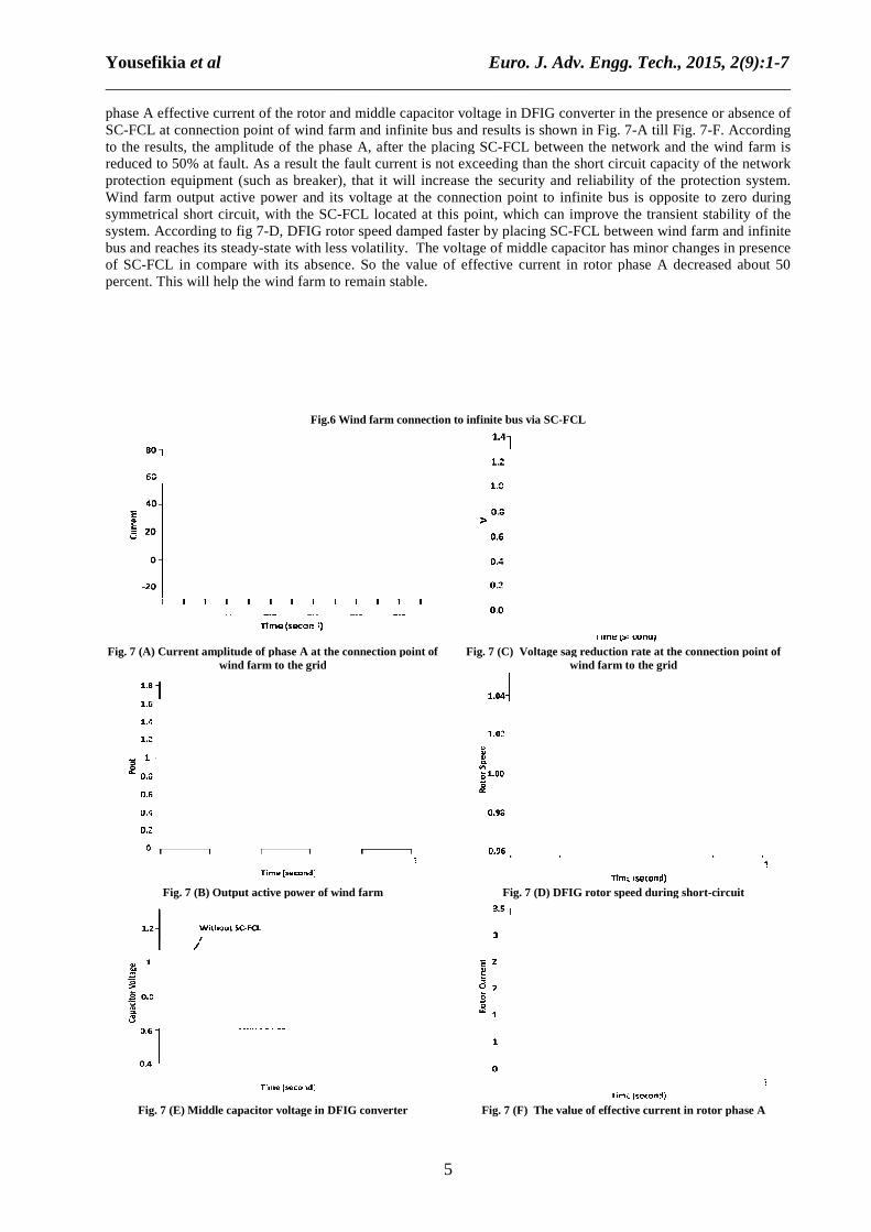
Fig. 7 (A) Current amplitude of phase A at the connection point wind farm to the grid
Fig. 7 (B) Output active power of wind farm
Fig. 7 (E) Middle capacitor voltage in
Euro. J. Adv. Engg. Tech., 201______________________________________________________________________________
5
phase A effective current of the rotor and middle capacitor voltage in DFIG converter in the presence or absence of FCL at connection point of wind farm and infinite bus and results is shown in Fig. 7
to the results, the amplitude of the phase A, after the placing SC-FCL between the network and the wind farm is reduced to 50% at fault. As a result the fault current is not exceeding than the short circuit capacity of the network protection equipment (such as breaker), that it will increase the security and reliability of thWind farm output active power and its voltage at the connection point to infinite bus is opposite to zero during symmetrical short circuit, with the SC-FCL located at this point, which can improve the transient stability of the
D, DFIG rotor speed damped faster by placing SC-FCL between wind farm and infinite state with less volatility. The voltage of middle capacitor has minor changes in presence
FCL in compare with its absence. So the value of effective current in rotor phase A decreased about 50 percent. This will help the wind farm to remain stable.
Fig.6 Wind farm connection to infinite bus via SC-FCL
urrent amplitude of phase A at the connection point of wind farm to the grid
Fig. 7 (C) Voltage sag reduction rate at the connection point of wind farm to the grid
utput active power of wind farm Fig. 7 (D) DFIG rotor speed during short
iddle capacitor voltage in DFIG converter Fig. 7 (F) The value of effective current in rotor phase A
Euro. J. Adv. Engg. Tech., 2015, 2(9):1-7 ______________________________________________________________________________
dle capacitor voltage in DFIG converter in the presence or absence of 7-A till Fig. 7-F. According
between the network and the wind farm is reduced to 50% at fault. As a result the fault current is not exceeding than the short circuit capacity of the network protection equipment (such as breaker), that it will increase the security and reliability of the protection system. Wind farm output active power and its voltage at the connection point to infinite bus is opposite to zero during
FCL located at this point, which can improve the transient stability of the FCL between wind farm and infinite
state with less volatility. The voltage of middle capacitor has minor changes in presence ce. So the value of effective current in rotor phase A decreased about 50
Voltage sag reduction rate at the connection point of
wind farm to the grid
DFIG rotor speed during short-circuit
value of effective current in rotor phase A
Yousefikia et al ______________________________________________________________________________
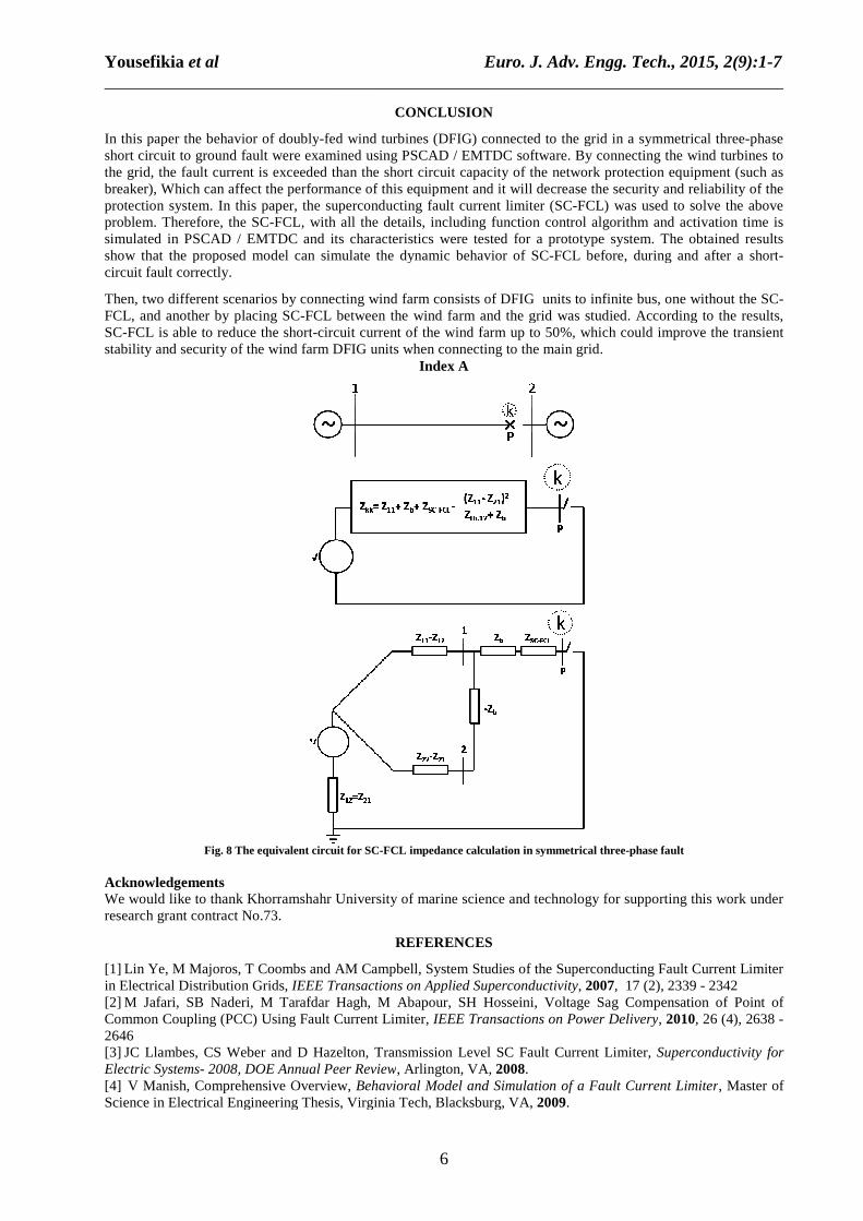
In this paper the behavior of doublyshort circuit to ground fault were examined using PSCAD / EMTDC software. By connecting the wind turbines to the grid, the fault current is exceeded than the short circuit capacity of the network protection equipment (such as breaker), Which can affect the performance of this equipment and it will decrease the security and reliability of the protection system. In this paper, the superconducting fproblem. Therefore, the SC-FCL, with all the details, including function control algorithm and activation time is simulated in PSCAD / EMTDC and its characteristics show that the proposed model can simulate the dynamic behavior of SCcircuit fault correctly.
Then, two different scenarios by connecting wind farm consists of DFIG FCL, and another by placing SC-FCL between the wind farm and the grid was studied. According to the results, SC-FCL is able to reduce the shortstability and security of the wind farm DFIG units when connecting to the main grid.
Fig. 8 The equivalent circuit for SC Acknowledgements We would like to thank Khorramshahr University of marine science and technology for supporting this work under research grant contract No.73.
[1] Lin Ye, M Majoros, T Coombs and AM Campbell, System Studies of the Superconducting Fault Current Limin Electrical Distribution Grids, IEEE Transactions on Applied Superconductivity[2] M Jafari, SB Naderi, M Tarafdar Hagh, M Abapour, SH Hosseini, Voltage Sag Compensation of Point of Common Coupling (PCC) Using Fault Current Limiter, 2646 [3] JC Llambes, CS Weber and D Hazelton, TransmElectric Systems- 2008, DOE Annual Peer Review[4] V Manish, Comprehensive Overview, Science in Electrical Engineering Thesis, Virginia Tech, Blacksburg, VA,
Euro. J. Adv. Engg. Tech., 201______________________________________________________________________________
6
CONCLUSION
In this paper the behavior of doubly-fed wind turbines (DFIG) connected to the grid in a symmetrical threeshort circuit to ground fault were examined using PSCAD / EMTDC software. By connecting the wind turbines to
eeded than the short circuit capacity of the network protection equipment (such as breaker), Which can affect the performance of this equipment and it will decrease the security and reliability of the protection system. In this paper, the superconducting fault current limiter (SC-FCL) was used to solve the above
FCL, with all the details, including function control algorithm and activation time is simulated in PSCAD / EMTDC and its characteristics were tested for a prototype system. The obtained results show that the proposed model can simulate the dynamic behavior of SC-FCL before, during and after a short
Then, two different scenarios by connecting wind farm consists of DFIG units to infinite bus, one without the SCFCL between the wind farm and the grid was studied. According to the results,
FCL is able to reduce the short-circuit current of the wind farm up to 50%, which could improve the tstability and security of the wind farm DFIG units when connecting to the main grid.
Index A
The equivalent circuit for SC-FCL impedance calculation in symmetrical three
We would like to thank Khorramshahr University of marine science and technology for supporting this work under
REFERENCES
Lin Ye, M Majoros, T Coombs and AM Campbell, System Studies of the Superconducting Fault Current LimIEEE Transactions on Applied Superconductivity, 2007, 17 (2),
M Jafari, SB Naderi, M Tarafdar Hagh, M Abapour, SH Hosseini, Voltage Sag Compensation of Point of Common Coupling (PCC) Using Fault Current Limiter, IEEE Transactions on Power Delivery
JC Llambes, CS Weber and D Hazelton, Transmission Level SC Fault Current Limiter, 2008, DOE Annual Peer Review, Arlington, VA, 2008.
V Manish, Comprehensive Overview, Behavioral Model and Simulation of a Fault Current LimiterEngineering Thesis, Virginia Tech, Blacksburg, VA, 2009.
Euro. J. Adv. Engg. Tech., 2015, 2(9):1-7 ______________________________________________________________________________
fed wind turbines (DFIG) connected to the grid in a symmetrical three-phase short circuit to ground fault were examined using PSCAD / EMTDC software. By connecting the wind turbines to
eeded than the short circuit capacity of the network protection equipment (such as breaker), Which can affect the performance of this equipment and it will decrease the security and reliability of the
FCL) was used to solve the above FCL, with all the details, including function control algorithm and activation time is
tested for a prototype system. The obtained results FCL before, during and after a short-
units to infinite bus, one without the SC-FCL between the wind farm and the grid was studied. According to the results,
circuit current of the wind farm up to 50%, which could improve the transient
FCL impedance calculation in symmetrical three-phase fault
We would like to thank Khorramshahr University of marine science and technology for supporting this work under
Lin Ye, M Majoros, T Coombs and AM Campbell, System Studies of the Superconducting Fault Current Limiter , 17 (2), 2339 - 2342
M Jafari, SB Naderi, M Tarafdar Hagh, M Abapour, SH Hosseini, Voltage Sag Compensation of Point of IEEE Transactions on Power Delivery, 2010, 26 (4), 2638 -
ission Level SC Fault Current Limiter, Superconductivity for
Behavioral Model and Simulation of a Fault Current Limiter, Master of

Yousefikia et al Euro. J. Adv. Engg. Tech., 2015, 2(9):1-7 ______________________________________________________________________________
7
[5] S Kalsi and A Malozemoff, Resistive High Temperature Superconductor Fault Current Limiter, The Power Delivery Applications of Superconductivity Task Force, New York, 2003. [6] S Gasemzadeh and SH Hosseini, Unified Modeling of Wind Power Station Including DFIG for Distributed Generation Studies, Journal of Faculty of Tabriz University(Electrical Eng.), 2008, 35 (1), 38-46 [7] JJ Grainger and WD Stevenson, Power System Analysis, New York: McGraw-Hill International Editions, 1994. [8] T Abedinzadeh, M Ehsan and DTalebi, Dynamic Modeling and Control of Induction Generators in Wind Turbines, International Journal of Computer and Electrical Engineering, 2012, 4 (2), 45-52 [9] T Abedinzadeh, Hadi Afsharirad and Mohammad Nazaraliloo, Modelling and Performance Analysis of Doubly-Fed Induction Wind Turbines Using PSCAD/EMTDC,Canadian Journal on Electrical and Electronics Engineering, 2012, 3 (1), 31-38 [10] Bart Diaz, Thomas H Ortmeyer, Bruce Pilvelait, Mike Izenson, Weibo Chen and Nathan Spivey, System Study of Fault Current Limiter for Shipboard Power System , IEEE, Electric Ship Technologies Symposium,2009. [11] Nand K Singh, Ryan M Tumilty, Graeme M Burt, Chris G Bright, Cornel C Brozio, DA Roberts, Alexander C Smith and Mark Husband, System-Level Studies of a MgB2 Superconducting Fault-Current Limiter in an Active Distribution Network , IEEE Transactions on Applied Superconductivity, 2010, 20 (2), 54 - 60 [12] M Stemmle, C Neumann, F Merschel, U Schwing, KH Weck, M Noe, F Breuer and S Elschner, Analysis of Unsymmetrical Faults in High Voltage Power Systems with Superconducting Fault Current Limiters, IEEE Transactions on Applied Superconductivity, 2007, 17 (2), 2347–2350. [13] Byung Chul Sung, Dong Keun Park, Jung-Wook Park and Tae Kuk Ko, Study on a Series Resistive SFCL to Improve Power System Transient Stability: Modeling, Simulation, and Experimental Verification, IEEE Transactions on Industrial Electronics, 2009, 56 (7), 2412 - 2419 [14] D Gautam, V Vittal and T Harbour, Impact of Increased Penetration of DFIG-Based Wind Turbine Generators on Transient and Small Signal Stability of Power Systems, IEEE Transaction on Power System, 2009, 24 (3), 1426–1434. [15] MS El-Moursi, MH Abdel-Rahman and B Bak-Jensen, Coordinated Voltage Control Scheme for SEIG-based Wind Park Utilizing Substation STATCOM and ULTC Transformer, IEEE Transaction on Sustainable Energy, 2011, 2 (3), 246–255.