surge protection & line conditioning catalog · leviton offers advanced surge suppression...
TRANSCRIPT
A Network Approach to Surge Protection and Line Conditioning
UL1449LISTED PRODUCTS
2ndEDITION
Revised September, 1999
Courtesy of Steven Engineering, Inc. ! 230 Ryan Way, South San Francisco, CA 94080-6370 ! Main Office: (650) 588-9200 ! Outside Local Area: (800) 258-9200 ! www.stevenengineering.com
Leviton offers advancedsurge suppression technologywith network application strategies, to give you unmatched protection.The quality and variety of Leviton surge protection devices (SPD’s) allows you
to optimize network protection by distributing it throughout a facility.
Panel-mounted devices are installed at the service entrance to immediately
reduce external surges. To prevent equipment damage from both internal and
external surges, we offer branch panel and point-of-use devices to fit all
environments and applications.
Leviton provides a single source for the SPD’s you need to connect and protect!Leviton point-of-use devices come in a variety of styles so you can choose what’s
right for your application, from hard-wired receptacles to plug-ins, plug-strips and a
specialized power control center for integrated computer work stations. They also
come in different grades to suit the needs of industrial, commercial and residential
environments.
Leviton’s wide selection of SPD’s provide various levels of protection, so you
can choose the one that’s appropriate for your equipment.
At Leviton, we are proud to state that we have been developing electrical and
electronic wiring devices for over 90 years. During that time, we have been active
in establishing industry-wide standards and educating the marketplace.
Our nationwide team of over 200 factory-employed salespeople and industrial
specialists has further established Leviton as a leading manufacturer of power
quality devices. We look forward to continuing our efforts in developing not only
innovative products but also in supporting our customers with effective power
quality solutions.
2
©1999 (September) Leviton Manufacturing Co., Inc. All rights reserved.Note: All information contained herein was accurate at time of publication. Because Leviton engages in a continuing program of product improvement, all data is subject to change without notice.
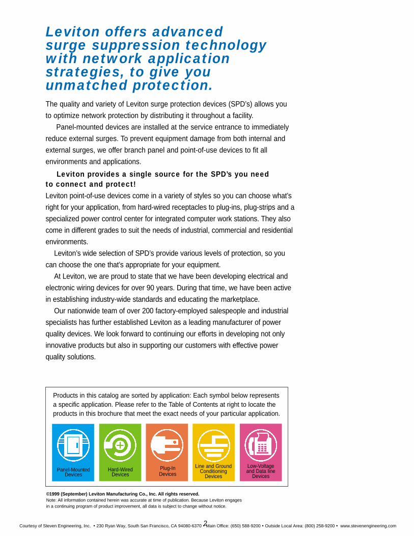
Products in this catalog are sorted by application: Each symbol below representsa specific application. Please refer to the Table of Contents at right to locate theproducts in this brochure that meet the exact needs of your particular application.
Panel-MountedDevices
Hard-WiredDevices
Plug-InDevices
Line and GroundConditioning
Devices
Low-Voltageand Data line
Devices
Courtesy of Steven Engineering, Inc. ! 230 Ryan Way, South San Francisco, CA 94080-6370 ! Main Office: (650) 588-9200 ! Outside Local Area: (800) 258-9200 ! www.stevenengineering.com
Table of Contents
Leviton’s network protection approach 5
An objective measure — IEEE C62 Standards 6
Testing to IEEE C62 Standard 7
UL verification of clamping data: Standard 1449 7
The NEMA LS-1 Specification Format 8
Application Environments (Including the Rockwell Automation Allen-BradleyENCOMPASS Program) 9
Leviton Support Services 9
Product Section 11
Cat. No. 57000 Panel-Mounted Devices 12
Cat. No. 52000 Panel-Mounted Devices 14
Cat. No. 52000-RS Remote Supervisor 14
Cat. No. 47000 Panel-Mounted Devices 17
Cat. No. 32000 Panel-Mounted Devices 19
Cat. No. 42000 Panel-Mounted Devices 19
Cat. No. 51120 Panel-Mounted Devices 22
Cat. No. 50240-MSA Meter Socket Surge Arrester Adapter 24
Cat. No. 51020 and 51240 Wired-Module Devices 26
Cat. No. 3800 Equipment Cabinet Devices 28
Cat. No. 3803-DPH and 3803-485 Communication Protection Modules 30
Surge Suppression Single and Duplex Receptacles 33
Four-In-One Surge Suppression Receptacles 35
Plug-In Devices 37
Plug-Strip Devices 40
Computer Grade, Commercial Grade and General Purpose Grade Devices 43
Cat. No. 5400 Power Control Center 45
Cat. No. 5500 Rack-Mounted Devices 46
Terms of Leviton Product Warranty and Downline Lifetime Limited Warranty 54
Index 55
Line and Ground Conditioning Devices 48
Stand-Alone Low-Voltage Communications/Data Line Devices 51
3
Courtesy of Steven Engineering, Inc. ! 230 Ryan Way, South San Francisco, CA 94080-6370 ! Main Office: (650) 588-9200 ! Outside Local Area: (800) 258-9200 ! www.stevenengineering.com

Above is a simplified example of the varied equipment which should beprotected by surge protective devices. The existence of mission-criticalelectronic equipment located throughout a facility leaves manyorganizations vulnerable to transient voltage surges.
1. Power Distribution
Load center Switchgear Distribution equipment
2. Electrical Loads
Lamps Ballasts Lighting controls
3. Building Controls
Building management systems Motor controls Drives
4. Computers & Communications
Voice/data equipment(PBX system, LAN’s, WAN’s)
Security system Fire alarm system Patch Panels UPS systems
Applications For Commercial /Light Industrial Facility
4
1.
2.
3.
4.
Courtesy of Steven Engineering, Inc. ! 230 Ryan Way, South San Francisco, CA 94080-6370 ! Main Office: (650) 588-9200 ! Outside Local Area: (800) 258-9200 ! www.stevenengineering.com
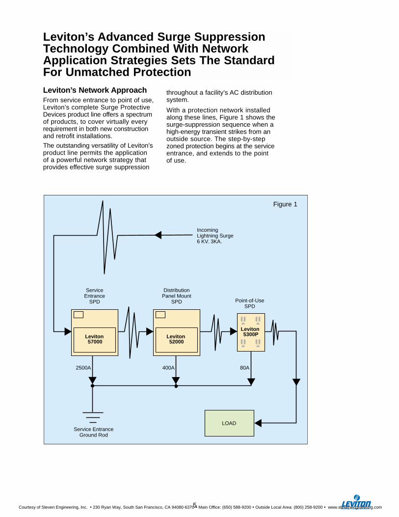
Leviton’s Network ApproachFrom service entrance to point of use,Leviton’s complete Surge ProtectiveDevices product line offers a spectrumof products, to cover virtually everyrequirement in both new constructionand retrofit installations.
The outstanding versatility of Leviton’sproduct line permits the application of a powerful network strategy thatprovides effective surge suppression
throughout a facility’s AC distributionsystem.
With a protection network installedalong these lines, Figure 1 shows thesurge-suppression sequence when ahigh-energy transient strikes from anoutside source. The step-by-stepzoned protection begins at the serviceentrance, and extends to the point of use.
Leviton’s Advanced Surge SuppressionTechnology Combined With NetworkApplication Strategies Sets The StandardFor Unmatched Protection
Leviton 5300PLeviton
52000Leviton 57000
IncomingLightning Surge6 KV. 3KA.
DistributionPanel Mount
SPD Point-of-UseSPD
LOAD
2500A 400A 80A
Service EntranceGround Rod
Service Entrance
SPD
Figure 1
5
Courtesy of Steven Engineering, Inc. ! 230 Ryan Way, South San Francisco, CA 94080-6370 ! Main Office: (650) 588-9200 ! Outside Local Area: (800) 258-9200 ! www.stevenengineering.com

When describing performanceof Surge Protective Devices,many factors play a part indetermining the effectiveness of these products. This canmake it difficult to carry out a reasonable comparisonbetween performance charac-teristics of competing products.Therefore, the Institute ofElectrical and ElectronicEngineers, or IEEE, establisheduniform requirements that characterize the environmentsfor evaluating the performanceof Surge Protective Devices.
Standard C62.41 describesthree general categories ofoperating environment forSurge Protective Devices. Asshown in Figure 2, the threesystem exposure environmentsare called Category A,Category B, and Category C.
With operating environment categories well defined, theIEEE also established a veryprecise description of severaltransient voltage and currentwaveforms that would beexpected within each of theseareas. The transient waveformsare configured as ringwavesand combination waves.Charts 1 and 2 show the exactparameters that describe thesewaveforms in Category A, Band C operating environments.
Note that for Categories Aand B, there are low, mediumand high-exposure ringwave transients shown in Chart 1. In Chart 2, there are low, medium and high-exposurecombination-wave transientlevels for Categories B and C.
ServiceEntrance Meter
Meter
Outbuilding
Underground Service
ServiceEntrance
OutbuildingTransformer
Underground Service
ServiceEntrance
A B C
Demarcation between Location Categories B and C is arbitrarily taken to be at the meter or at the mains disconnect (ANSI/NFPA 70-1990 2, Article 230-70) for low-voltage service, or at the secondary of service transformer if the service is provided to the user at a higher voltage.
A• Outlets & long
branch circuits
• All outlets at more than 10m (30ft.) from Category B
• All outlets at more than 20m (60ft.) from Category C
B• Feeders and short branch circuits• Distribution panel devices• Bus and feeder industrial plants• Heavy appliance outlets with “short”
connections to service entrance• Lighting systems in large buildings
C• Outside and
service entrance• Service drop from
pole to building• Run between
meter&panel• Overhead line to
detached building• Underground
line to well pump
Figure 2An Objective Measure OfSurge Protective DevicePerformance —The IEEE C62 StandardsCollection
6
Courtesy of Steven Engineering, Inc. ! 230 Ryan Way, South San Francisco, CA 94080-6370 ! Main Office: (650) 588-9200 ! Outside Local Area: (800) 258-9200 ! www.stevenengineering.com
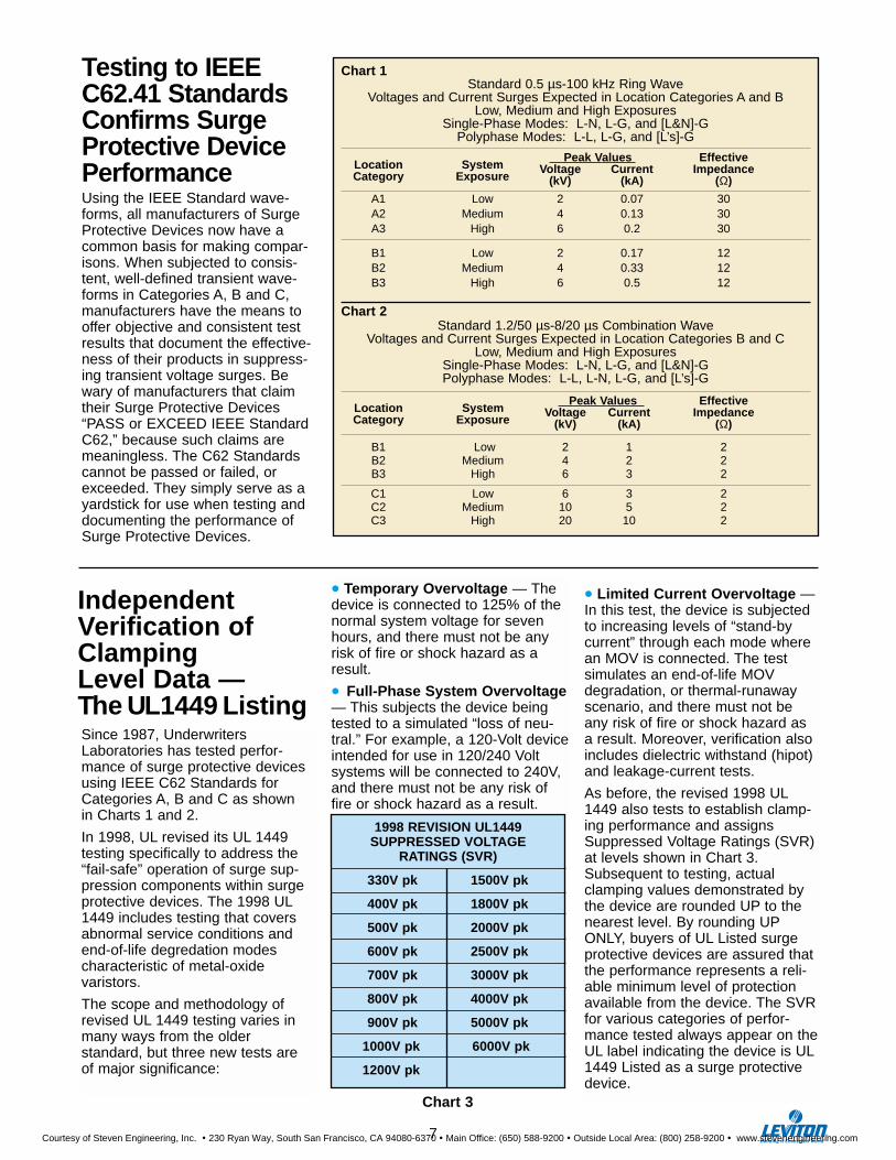
Since 1987, UnderwritersLaboratories has tested perfor-mance of surge protective devicesusing IEEE C62 Standards forCategories A, B and C as shown in Charts 1 and 2.
In 1998, UL revised its UL 1449testing specifically to address the“fail-safe” operation of surge sup-pression components within surgeprotective devices. The 1998 UL1449 includes testing that coversabnormal service conditions andend-of-life degredation modes characteristic of metal-oxide varistors.
The scope and methodology ofrevised UL 1449 testing varies inmany ways from the older standard, but three new tests are of major significance:
• Temporary Overvoltage — Thedevice is connected to 125% of thenormal system voltage for sevenhours, and there must not be anyrisk of fire or shock hazard as aresult.
• Full-Phase System Overvoltage— This subjects the device beingtested to a simulated “loss of neu-tral.” For example, a 120-Volt deviceintended for use in 120/240 Voltsystems will be connected to 240V,and there must not be any risk offire or shock hazard as a result.
• Limited Current Overvoltage —In this test, the device is subjectedto increasing levels of “stand-bycurrent” through each mode wherean MOV is connected. The testsimulates an end-of-life MOVdegradation, or thermal-runawayscenario, and there must not beany risk of fire or shock hazard asa result. Moreover, verification alsoincludes dielectric withstand (hipot)and leakage-current tests.
As before, the revised 1998 UL1449 also tests to establish clamp-ing performance and assignsSuppressed Voltage Ratings (SVR)at levels shown in Chart 3.Subsequent to testing, actualclamping values demonstrated bythe device are rounded UP to thenearest level. By rounding UPONLY, buyers of UL Listed surgeprotective devices are assured thatthe performance represents a reli-able minimum level of protectionavailable from the device. The SVRfor various categories of perfor-mance tested always appear on theUL label indicating the device is UL1449 Listed as a surge protectivedevice.
IndependentVerification ofClamping Level Data — The UL1449 Listing
1998 REVISION UL1449SUPPRESSED VOLTAGE
RATINGS (SVR)
330V pk 1500V pk
400V pk 1800V pk
500V pk 2000V pk
600V pk 2500V pk
700V pk 3000V pk
800V pk 4000V pk
900V pk 5000V pk
1000V pk 6000V pk
1200V pk
Chart 3
Chart 1Standard 0.5 µs-100 kHz Ring Wave
Voltages and Current Surges Expected in Location Categories A and BLow, Medium and High Exposures
Single-Phase Modes: L-N, L-G, and [L&N]-GPolyphase Modes: L-L, L-G, and [L’s]-G
Peak Values EffectiveLocation System Voltage Current ImpedanceCategory Exposure (kV) (kA) (Ω)
A1 Low 2 0.07 30A2 Medium 4 0.13 30A3 High 6 0.2 30
B1 Low 2 0.17 12B2 Medium 4 0.33 12B3 High 6 0.5 12
Chart 2Standard 1.2/50 µs-8/20 µs Combination Wave
Voltages and Current Surges Expected in Location Categories B and CLow, Medium and High Exposures
Single-Phase Modes: L-N, L-G, and [L&N]-GPolyphase Modes: L-L, L-N, L-G, and [L’s]-G
Peak Values Effective Location System Voltage Current ImpedanceCategory Exposure (kV) (kA) (Ω)
B1 Low 2 1 2B2 Medium 4 2 2B3 High 6 3 2
C1 Low 6 3 2C2 Medium 10 5 2C3 High 20 10 2
Testing to IEEEC62.41 StandardsConfirms SurgeProtective DevicePerformanceUsing the IEEE Standard wave-forms, all manufacturers of SurgeProtective Devices now have acommon basis for making compar-isons. When subjected to consis-tent, well-defined transient wave-forms in Categories A, B and C,manufacturers have the means tooffer objective and consistent testresults that document the effective-ness of their products in suppress-ing transient voltage surges. Bewary of manufacturers that claimtheir Surge Protective Devices“PASS or EXCEED IEEE StandardC62,” because such claims aremeaningless. The C62 Standardscannot be passed or failed, orexceeded. They simply serve as ayardstick for use when testing anddocumenting the performance ofSurge Protective Devices.
7
Courtesy of Steven Engineering, Inc. ! 230 Ryan Way, South San Francisco, CA 94080-6370 ! Main Office: (650) 588-9200 ! Outside Local Area: (800) 258-9200 ! www.stevenengineering.com
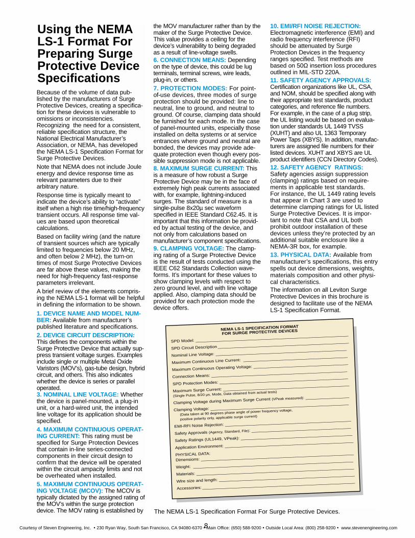
Using the NEMALS-1 Format ForPreparing SurgeProtective DeviceSpecifications
The NEMA LS-1 Specification Format For Surge Protective Devices.
Because of the volume of data pub-lished by the manufacturers of SurgeProtective Devices, creating a specifica-tion for these devices is vulnerable toomissions or inconsistencies.Recognizing the need for a consistent,reliable specification structure, theNational Electrical Manufacturer’sAssociation, or NEMA, has developedthe NEMA LS-1 Specification Format forSurge Protective Devices.Note that NEMA does not include Jouleenergy and device response time as relevant parameters due to their arbitrary nature.Response time is typically meant to indicate the device’s ability to “activate”itself when a high rise time/high-frequencytransient occurs. All response time val-ues are based upon theoretical calculations. Based on facility wiring (and the natureof transient sources which are typicallylimited to frequencies below 20 MHz,and often below 2 MHz), the turn-ontimes of most Surge Protective Devicesare far above these values, making theneed for high-frequency fast-responseparameters irrelevant.A brief review of the elements compris-ing the NEMA LS-1 format will be helpfulin defining the information to be shown.
1. DEVICE NAME AND MODEL NUM-BER: Available from manufacturer’spublished literature and specifications.2. DEVICE CIRCUIT DESCRIPTION:This defines the components within theSurge Protective Device that actually sup-press transient voltage surges. Examplesinclude single or multiple Metal OxideVaristors (MOV’s), gas-tube design, hybridcircuit, and others. This also indicateswhether the device is series or paralleloperated.3. NOMINAL LINE VOLTAGE: Whetherthe device is panel-mounted, a plug-inunit, or a hard-wired unit, the intendedline voltage for its application should bespecified.4. MAXIMUM CONTINUOUS OPERAT-ING CURRENT: This rating must bespecified for Surge Protection Devicesthat contain in-line series-connectedcomponents in their circuit design toconfirm that the device will be operatedwithin the circuit ampacity limits and notbe overheated when installed.5. MAXIMUM CONTINUOUS OPERAT-ING VOLTAGE (MCOV): The MCOV istypically dictated by the assigned rating ofthe MOV’s within the surge protectiondevice. The MOV rating is established by
the MOV manufacturer rather than by themaker of the Surge Protective Device.This value provides a ceiling for thedevice’s vulnerability to being degradedas a result of line-voltage swells.6. CONNECTION MEANS: Dependingon the type of device, this could be lug terminals, terminal screws, wire leads,plug-in, or others.7. PROTECTION MODES: For point-of-use devices, three modes of surge protection should be provided: line toneutral, line to ground, and neutral toground. Of course, clamping data shouldbe furnished for each mode. In the caseof panel-mounted units, especially thoseinstalled on delta systems or at serviceentrances where ground and neutral arebonded, the devices may provide ade-quate protection even though every pos-sible suppression mode is not applicable. 8. MAXIMUM SURGE CURRENT: Thisis a measure of how robust a SurgeProtective Device may be in the face ofextremely high peak currents associatedwith, for example, lightning-inducedsurges. The standard of measure is asingle-pulse 8x20µ sec waveform specified in IEEE Standard C62.45. It isimportant that this information be provid-ed by actual testing of the device, andnot only from calculations based on manufacturer’s component specifications.9. CLAMPING VOLTAGE: The clamp-ing rating of a Surge Protective Deviceis the result of tests conducted using theIEEE C62 Standards Collection wave-forms. It’s important for these values toshow clamping levels with respect tozero ground level, and with line voltageapplied. Also, clamping data should beprovided for each protection mode thedevice offers.
10. EMI/RFI NOISE REJECTION:Electromagnetic interference (EMI) andradio frequency interference (RFI)should be attenuated by SurgeProtection Devices in the frequencyranges specified. Test methods arebased on 50Ω insertion loss proceduresoutlined in MIL-STD 220A.11. SAFETY AGENCY APPROVALS:Certification organizations like UL, CSA,and NOM, should be specified along withtheir appropriate test standards, productcategories, and reference file numbers.For example, in the case of a plug strip,the UL listing would be based on evalua-tion under standards UL 1449 TVSS(XUHT) and also UL 1363 TemporaryPower Taps (XBYS). In addition, manufac-turers are assigned file numbers for theirlisted devices. XUHT and XBYS are ULproduct identifiers (CCN Directory Codes).12. SAFETY AGENCY RATINGS:Safety agencies assign suppression(clamping) ratings based on require-ments in applicable test standards. For instance, the UL 1449 rating levelsthat appear in Chart 3 are used todetermine clamping ratings for UL listedSurge Protective Devices. It is impor-tant to note that CSA and UL both prohibit outdoor installation of thesedevices unless they’re protected by anadditional suitable enclosure like aNEMA-3R box, for example.13. PHYSICAL DATA: Available frommanufacturer’s specifications, this entryspells out device dimensions, weights,materials composition and other physi-cal characteristics.The information on all Leviton SurgeProtective Devices in this brochure isdesigned to facilitate use of the NEMALS-1 Specification Format.
NEMA LS-1 SPECIFICATION FORMAT
FOR SURGE PROTECTIVE DEVICES
SPD Model: _______________________________________________________________
SPD Circuit Description ______________________________________________________
Nominal Line VoItage: ______________________________________________________
Maximum Continuous Line Current: ___________________________________________
Maximum Continuous Operating VoItage: _______________________________________
Connection Means: ________________________________________________________
SPD Protection Modes: _____________________________________________________
Maximum Surge Current: ____________________________________________________
(Single Pulse, 8/20 µs, Mode, Data obtained from actual tests)
Clamping VoItage during Maximum Surge Current (VPeak measured): __________________
Clamping Voltage: _________________________________________________________
(Data taken at 90 degrees phase angle of power frequency voltage,
positive polarity only, applicable surge current)
EMI-RFI Noise Rejection: ____________________________________________________
Safety Approvals (Agency, Standard, File): _________________________________________
Safety Ratings (UL1449, VPeak): ______________________________________________
Application Environment: _____________________________________________________
PHYSICAL DATA:
Dimensions: _______________________________________________________________
Weight: __________________________________________________________________
Materials: _________________________________________________________________
Wlre size and length: ________________________________________________________
Accessories: _______________________________________________________________
8
Courtesy of Steven Engineering, Inc. ! 230 Ryan Way, South San Francisco, CA 94080-6370 ! Main Office: (650) 588-9200 ! Outside Local Area: (800) 258-9200 ! www.stevenengineering.com

Defending Against TransientVoltage Surges In Industrial,Commercial andResidential Settings
For the demands of industrial environments, Leviton provides a selection of surge protectivedevices that can be wired in at service panels, branch panels,
and at load sites. These devices are provided ina broad selection of ratings from 120V AC
single-phase to 600V AC three-phase DELTA.
LevitonBacks You With StrongSupportPower Quality Site Surveys
Leviton specialists can conductpower-quality audits in any facility.By means of sophisticated electronicsurge counters, the level of voltagetransients, and their severity, can be monitored. Using a site surveyworkbook, Leviton specialists canprepare a report that outlines: • Equipment at risk. • Potential losses due to downtime. • Recommended surge protective
devices.• Effective application strategies.
Power Quality Learning Labs
Leviton’s technical specialists canpresent a comprehensive seminarthat covers all aspects of powerquality, with an emphasis on transient voltage surge suppression.
The information presented includestypes of surges, their origins, andeffects. It also examines differentsurge protective devices, appropri-ate applications, and network protection strategies.
Superior Warranty Protection
For many of its industrial gradesurge protective devices, Levitonprovides a Lifetime LimitedDownline Warranty. This warranty
covers not only the surge protectivedevice, but also the equipment itprotects. To see the provisions ofthis warranty, and also of Leviton’sLimited Ten Year Warranty, refer topages 54 and 44 respectively.
Fast Answers To TechnicalQuestions
Trained technical specialists staffLeviton’s Techline. The toll-freeTechline number is (800) 824-3005.
Commercial and institutional facilities are equipped with a largevariety of electronic equipmentthat’s vital to their operation.Leviton has the surge protection
solutions that defend this equipmentagainst the effects of transient voltagesurges. In business offices, schools,retail stores, malls, banks, governmentfacilities and elsewhere, Leviton
devices can protect individualitems of equipment, entirebranch circuits, and evenentire facilities, starting at the
electrical service entrance.
Virtually every home contains microprocessor-driven electronicequipment, particularly with theincreased popularity of home officesand home entertainment centers.Leviton provides high-performancesurge protective devices tosafe-guard computer workstations and peripherals,televisions, audio equipment, and all other household electronics.
9
Leviton also provides surge protective devices designedfor use in programmable-logiccontrollers, factory-automationand data links using Allen-Bradley controllers operating on “Blue Hose” networks. Leviton is a participating supplier in RockwellAutomation’s EncompassProgram.
Courtesy of Steven Engineering, Inc. ! 230 Ryan Way, South San Francisco, CA 94080-6370 ! Main Office: (650) 588-9200 ! Outside Local Area: (800) 258-9200 ! www.stevenengineering.com
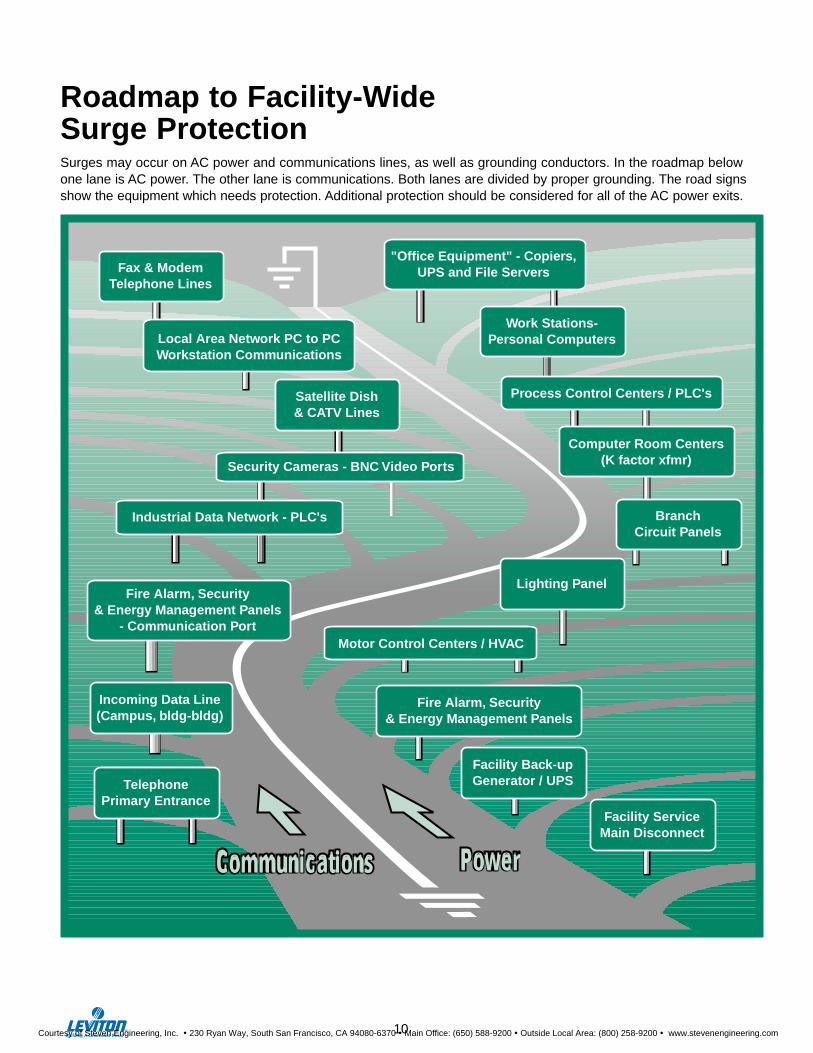
Communications Power
TelephonePrimary Entrance
Fax & ModemTelephone Lines
Local Area Network PC to PCWorkstation Communications
Satellite Dish& CATV Lines
Security Cameras - BNC Video Ports
Industrial Data Network - PLC's
"Office Equipment" - Copiers,UPS and File Servers
Work Stations-Personal Computers
Process Control Centers / PLC's
Computer Room Centers(K factor xfmr)
BranchCircuit Panels
Lighting PanelFire Alarm, Security
& Energy Management Panels- Communication Port
Incoming Data Line(Campus, bldg-bldg)
Fire Alarm, Security& Energy Management Panels
Facility Back-upGenerator / UPS
Facility ServiceMain Disconnect
Motor Control Centers / HVAC
Roadmap to Facility-Wide Surge Protection
10
Surges may occur on AC power and communications lines, as well as grounding conductors. In the roadmap below one lane is AC power. The other lane is communications. Both lanes are divided by proper grounding. The road signs show the equipment which needs protection. Additional protection should be considered for all of the AC power exits.
Courtesy of Steven Engineering, Inc. ! 230 Ryan Way, South San Francisco, CA 94080-6370 ! Main Office: (650) 588-9200 ! Outside Local Area: (800) 258-9200 ! www.stevenengineering.com

PAN
EL
MO
UN
TE
D D
EV
ICE
SPanel-MountedSurge ProtectiveDevicesInstalled at the service entrance, Leviton’s panel-mounted SPD’s serve as the first line of defenseagainst transients originating from outside a facility.When mounted at sub-panels, these SPD’s can protect entire branch circuits, or provide a dedicated feed to selected equipment.
11
Courtesy of Steven Engineering, Inc. ! 230 Ryan Way, South San Francisco, CA 94080-6370 ! Main Office: (650) 588-9200 ! Outside Local Area: (800) 258-9200 ! www.stevenengineering.com
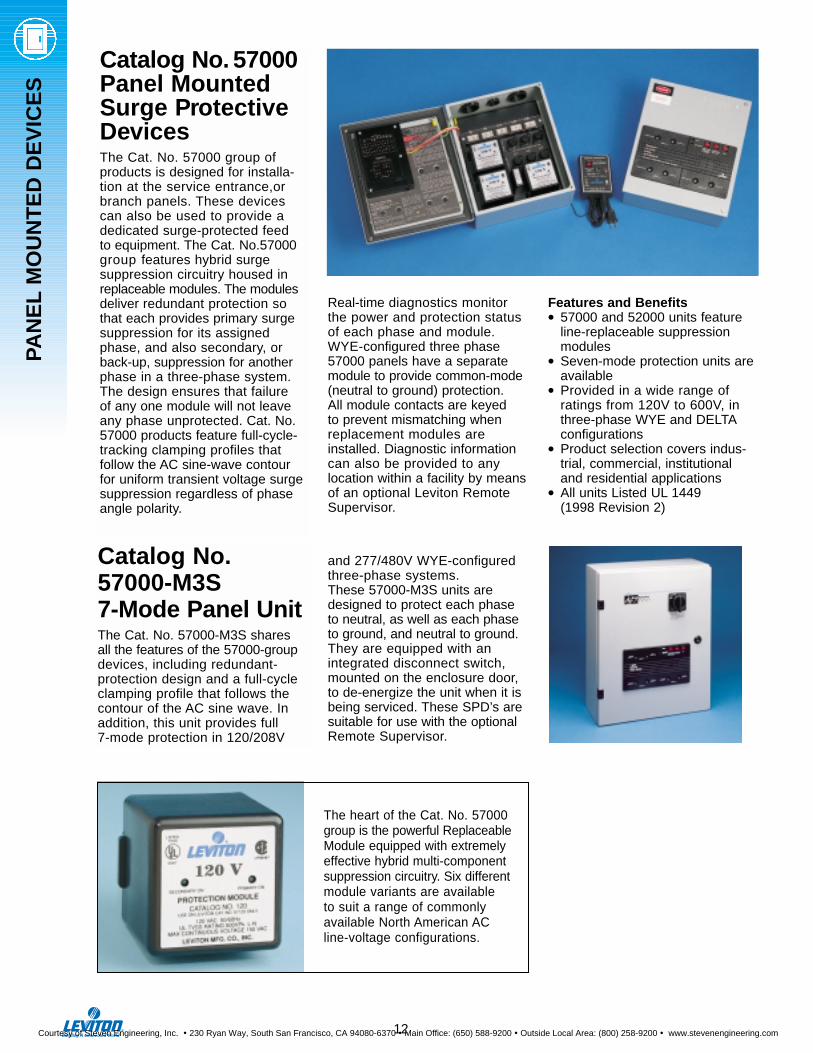
The heart of the Cat. No. 57000group is the powerful ReplaceableModule equipped with extremelyeffective hybrid multi-componentsuppression circuitry. Six differentmodule variants are available to suit a range of commonly available North American AC line-voltage configurations.
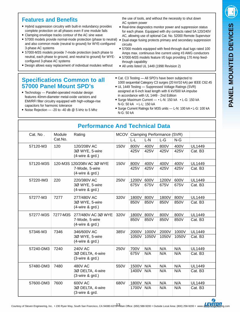
Catalog No. 57000Panel MountedSurge ProtectiveDevicesThe Cat. No. 57000 group of products is designed for installa-tion at the service entrance,orbranch panels. These devices can also be used to provide adedicated surge-protected feed to equipment. The Cat. No.57000group features hybrid surge suppression circuitry housed inreplaceable modules. The modulesdeliver redundant protection sothat each provides primary surgesuppression for its assignedphase, and also secondary, orback-up, suppression for anotherphase in a three-phase system.The design ensures that failure of any one module will not leaveany phase unprotected. Cat. No.57000 products feature full-cycle-tracking clamping profiles that follow the AC sine-wave contourfor uniform transient voltage surgesuppression regardless of phaseangle polarity.
Catalog No.57000-M3S7-Mode Panel UnitThe Cat. No. 57000-M3S shares all the features of the 57000-groupdevices, including redundant-protection design and a full-cycleclamping profile that follows thecontour of the AC sine wave. Inaddition, this unit provides full 7-mode protection in 120/208V
PAN
EL
MO
UN
TE
D D
EV
ICE
S
Real-time diagnostics monitor the power and protection statusof each phase and module. WYE-configured three phase57000 panels have a separatemodule to provide common-mode(neutral to ground) protection. All module contacts are keyed to prevent mismatching whenreplacement modules areinstalled. Diagnostic informationcan also be provided to any location within a facility by meansof an optional Leviton RemoteSupervisor.
Features and Benefits • 57000 and 52000 units feature
line-replaceable suppression modules
• Seven-mode protection units areavailable
• Provided in a wide range of ratings from 120V to 600V, inthree-phase WYE and DELTAconfigurations
• Product selection covers indus-trial, commercial, institutional and residential applications
• All units Listed UL 1449 (1998 Revision 2)
and 277/480V WYE-configured three-phase systems.These 57000-M3S units aredesigned to protect each phase to neutral, as well as each phase to ground, and neutral to ground.They are equipped with an integrated disconnect switch,mounted on the enclosure door, to de-energize the unit when it isbeing serviced. These SPD’s aresuitable for use with the optionalRemote Supervisor.
12
Courtesy of Steven Engineering, Inc. ! 230 Ryan Way, South San Francisco, CA 94080-6370 ! Main Office: (650) 588-9200 ! Outside Local Area: (800) 258-9200 ! www.stevenengineering.com
PAN
EL
MO
UN
TE
D D
EV
ICE
S
Features and Benefits• Hybrid suppression circuitry with built-in redundancy provides
complete protection on all phases even if one module fails• Clamping envelope tracks contour of the AC sine wave• 57000 models provide normal-mode protection (phase to neutral)
and also common mode (neutral to ground) for WYE-configured 3-phase AC systems
• 57000-M3S models provide 7-mode protection (each phase to neutral, each phase to ground, and neutral to ground) for WYE-configured 3-phase AC systems
• Design allows easy replacement of individual modules without
Specifications Common to all57000 Panel Mount SPD’s• Technology — Parallel-operated modular design
features 40mm-diameter metal-oxide varistors and EMI/RFI filter circuitry equipped with high-voltage-rise capacitors for harmonic tolerance
• Noise Rejection — -20 to -40 db @ 5 kHz to 5 Mhz
• Cat. C3 Testing — All SPD’s have been subjected to 1000 sequential Category C3 surges (20 kV/10 kA) per IEEE C62.45
• UL 1449 Testing — Suppressed Voltage Ratings (SVR) assigned at 6-inch lead length with 6 kV/500 kA impulsein accordance with UL 1449 - 2nd Edition
• Surge Maximum Current — • L-N: 150 kA • L-G: 150 kAN-G: 50 kA • L-L: 150 kA
• Surge Current Ratings for M3S units — L-N: 100 kA • L-G: 100 kAN-G: 50 kA
the use of tools, and without the necessity to shut down AC system power
• Real-time diagnostics monitor power and suppression status for each phase. Equipped with dry contacts rated 5A 120/240VAC, allowing use of optional Cat. No. 52000 Remote Supervisor
• Dual-stage fusing protects primary and secondary suppression circuits
• 57000 models equipped with feed-through dual lugs rated 100 Amps max. continuous line current using #3 AWG conductors
• 57000-M3S models feature I/0 lugs providing 170 Amp feed-through capability
• All units listed UL 1449 (1998 Revision 2)
Performance And Technical DataCat. No . Module Rating MCOV Clamping Performance (SVR)
Cat.No. L-L L-N L-G N-G
57120-M3 120 120/208V AC 150V 800V 400V 800V 400V UL14493Ø WYE, 5-wire 425V 425V 425V 425V Cat. B3(4-wire & grd.)
57120-M3S 120-M3S 120/208V AC 3Ø WYE 150V 800V 400V 400V 400V UL14497-Mode, 5-wire 425V 425V 425V 425V Cat. B3(4-wire & grd.)
57220-IM3 220 220/380V AC 250V 1200V 600V 1200V 600V UL14493Ø WYE, 5-wire 675V 675V 675V 675V Cat. B3(4-wire & grd.)
57277-M3 7277 277/480V AC 320V 1800V 800V 1800V 800V UL14493Ø WYE, 5-wire 850V 850V 850V 850V Cat. B3(4-wire & grd.)
57277-M3S 7277-M3S 277/480V AC 3Ø WYE 320V 1800V 800V 800V 800V UL14497-Mode, 5-wire 850V 850V 850V 850V Cat. B3(4-wire & grd.)
57346-M3 7346 346/600V AC 385V 2000V 1000V 2000V 1000V UL14493Ø WYE, 5-wire 1050V 1050V 1050V 1050V Cat. B3(4-wire & grd.)
57240-DM3 7240 240V AC 250V 700V N/A N/A N/A UL14493Ø DELTA, 4-wire 675V N/A N/A N/A Cat. B3(3-wire & grd.)
57480-DM3 7480 480V AC 550V 1500V N/A N/A N/A UL14493Ø DELTA, 4-wire 1400V N/A N/A N/A Cat. B3(3-wire & grd.)
57600-DM3 7600 600V AC 680V 1800V N/A N/A N/A UL14493Ø DELTA, 4-wire 1700V N/A N/A N/A Cat. B3(3-wire & grd.
13
Courtesy of Steven Engineering, Inc. ! 230 Ryan Way, South San Francisco, CA 94080-6370 ! Main Office: (650) 588-9200 ! Outside Local Area: (800) 258-9200 ! www.stevenengineering.com
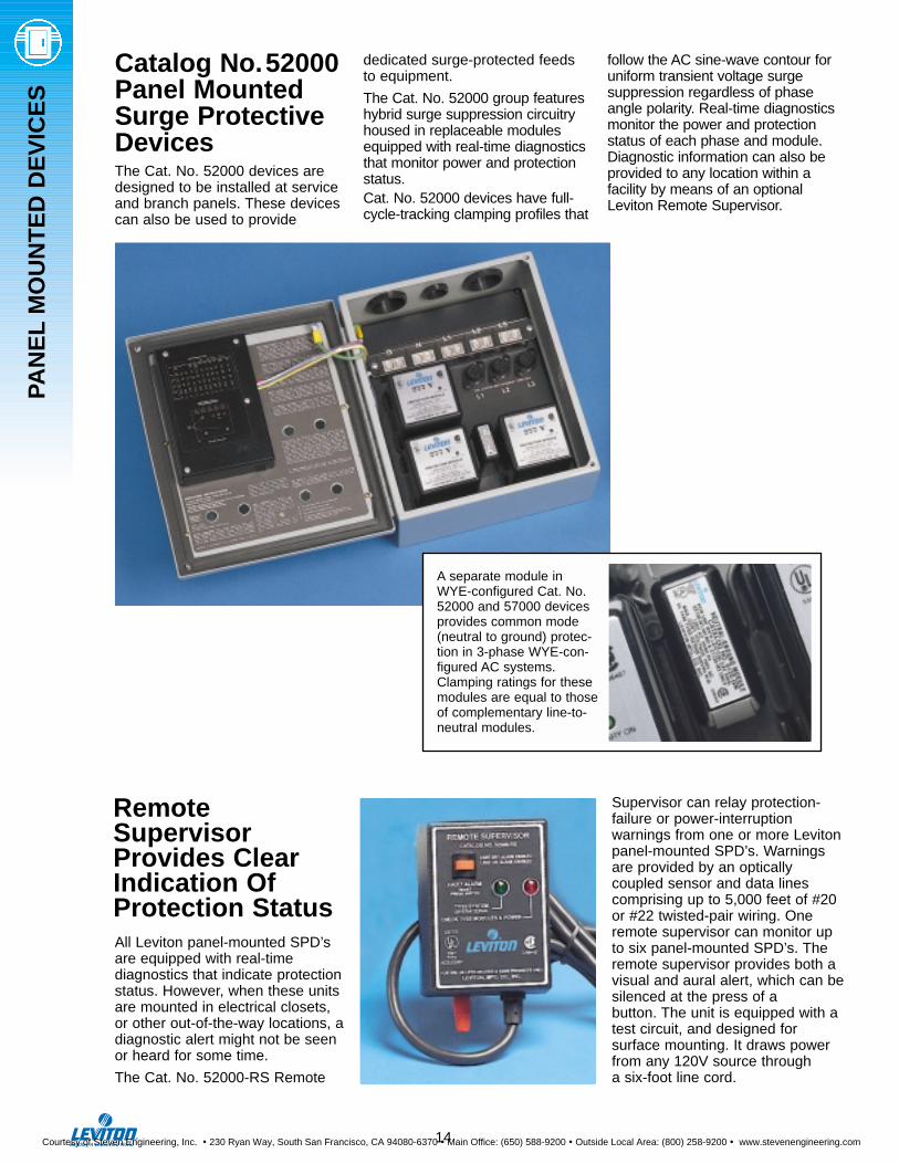
Catalog No.52000Panel MountedSurge ProtectiveDevicesThe Cat. No. 52000 devices aredesigned to be installed at serviceand branch panels. These devicescan also be used to provide
dedicated surge-protected feeds to equipment.
The Cat. No. 52000 group featureshybrid surge suppression circuitryhoused in replaceable modulesequipped with real-time diagnosticsthat monitor power and protectionstatus. Cat. No. 52000 devices have full-cycle-tracking clamping profiles that
follow the AC sine-wave contour foruniform transient voltage surge suppression regardless of phaseangle polarity. Real-time diagnosticsmonitor the power and protectionstatus of each phase and module.Diagnostic information can also beprovided to any location within afacility by means of an optionalLeviton Remote Supervisor.
PAN
EL
MO
UN
TE
D D
EV
ICE
S
Supervisor can relay protection-failure or power-interruption warnings from one or more Levitonpanel-mounted SPD’s. Warningsare provided by an optically coupled sensor and data linescomprising up to 5,000 feet of #20or #22 twisted-pair wiring. Oneremote supervisor can monitor upto six panel-mounted SPD’s. Theremote supervisor provides both avisual and aural alert, which can besilenced at the press of a button. The unit is equipped with atest circuit, and designed for surface mounting. It draws powerfrom any 120V source through a six-foot line cord.
RemoteSupervisorProvides ClearIndication OfProtection StatusAll Leviton panel-mounted SPD’sare equipped with real-time diagnostics that indicate protectionstatus. However, when these unitsare mounted in electrical closets,or other out-of-the-way locations, adiagnostic alert might not be seenor heard for some time.
The Cat. No. 52000-RS Remote
A separate module inWYE-configured Cat. No.52000 and 57000 devicesprovides common mode(neutral to ground) protec-tion in 3-phase WYE-con-figured AC systems.Clamping ratings for thesemodules are equal to thoseof complementary line-to-neutral modules.
14
Courtesy of Steven Engineering, Inc. ! 230 Ryan Way, South San Francisco, CA 94080-6370 ! Main Office: (650) 588-9200 ! Outside Local Area: (800) 258-9200 ! www.stevenengineering.com
PAN
EL
MO
UN
TE
D D
EV
ICE
S
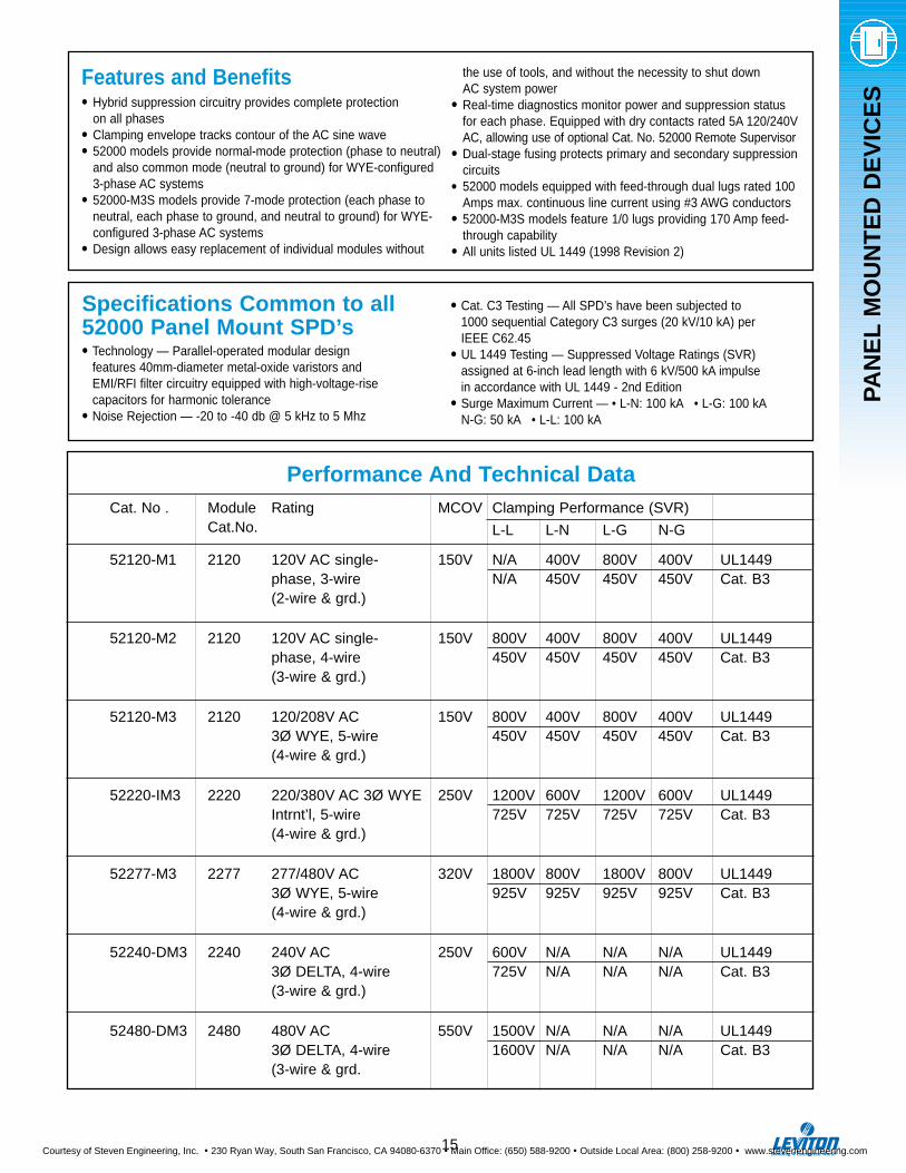
Features and Benefits• Hybrid suppression circuitry provides complete protection
on all phases• Clamping envelope tracks contour of the AC sine wave• 52000 models provide normal-mode protection (phase to neutral)
and also common mode (neutral to ground) for WYE-configured 3-phase AC systems
• 52000-M3S models provide 7-mode protection (each phase to neutral, each phase to ground, and neutral to ground) for WYE-configured 3-phase AC systems
• Design allows easy replacement of individual modules without
Specifications Common to all52000 Panel Mount SPD’s• Technology — Parallel-operated modular design
features 40mm-diameter metal-oxide varistors and EMI/RFI filter circuitry equipped with high-voltage-rise capacitors for harmonic tolerance
• Noise Rejection — -20 to -40 db @ 5 kHz to 5 Mhz
• Cat. C3 Testing — All SPD’s have been subjected to 1000 sequential Category C3 surges (20 kV/10 kA) per IEEE C62.45
• UL 1449 Testing — Suppressed Voltage Ratings (SVR) assigned at 6-inch lead length with 6 kV/500 kA impulsein accordance with UL 1449 - 2nd Edition
• Surge Maximum Current — • L-N: 100 kA • L-G: 100 kAN-G: 50 kA • L-L: 100 kA
the use of tools, and without the necessity to shut down AC system power
• Real-time diagnostics monitor power and suppression status for each phase. Equipped with dry contacts rated 5A 120/240VAC, allowing use of optional Cat. No. 52000 Remote Supervisor
• Dual-stage fusing protects primary and secondary suppression circuits
• 52000 models equipped with feed-through dual lugs rated 100 Amps max. continuous line current using #3 AWG conductors
• 52000-M3S models feature 1/0 lugs providing 170 Amp feed-through capability
• All units listed UL 1449 (1998 Revision 2)
15
Performance And Technical DataCat. No . Module Rating MCOV Clamping Performance (SVR)
Cat.No. L-L L-N L-G N-G
52120-M1 2120 120V AC single- 150V N/A 400V 800V 400V UL1449phase, 3-wire N/A 450V 450V 450V Cat. B3(2-wire & grd.)
52120-M2 2120 120V AC single- 150V 800V 400V 800V 400V UL1449phase, 4-wire 450V 450V 450V 450V Cat. B3(3-wire & grd.)
52120-M3 2120 120/208V AC 150V 800V 400V 800V 400V UL14493Ø WYE, 5-wire 450V 450V 450V 450V Cat. B3(4-wire & grd.)
52220-IM3 2220 220/380V AC 3Ø WYE 250V 1200V 600V 1200V 600V UL1449Intrnt’l, 5-wire 725V 725V 725V 725V Cat. B3(4-wire & grd.)
52277-M3 2277 277/480V AC 320V 1800V 800V 1800V 800V UL14493Ø WYE, 5-wire 925V 925V 925V 925V Cat. B3(4-wire & grd.)
52240-DM3 2240 240V AC 250V 600V N/A N/A N/A UL14493Ø DELTA, 4-wire 725V N/A N/A N/A Cat. B3(3-wire & grd.)
52480-DM3 2480 480V AC 550V 1500V N/A N/A N/A UL14493Ø DELTA, 4-wire 1600V N/A N/A N/A Cat. B3(3-wire & grd.
Courtesy of Steven Engineering, Inc. ! 230 Ryan Way, South San Francisco, CA 94080-6370 ! Main Office: (650) 588-9200 ! Outside Local Area: (800) 258-9200 ! www.stevenengineering.com
PAN
EL
MO
UN
TE
D D
EV
ICE
S
16
DANGER
HIGH VOLTAGEHaute Tension
SECONDARY-ON MODULE 1 PRIMARY-ON
SECONDARY-ON MODULE 2 PRIMARY-ON SECONDARY-ON MODULE 3 PRIMARY-ON
FAULT
LOW BATTERY
12 in304.8 mm
14.1 in358.1 mm
15.1 in383.5 mm
12.1 in307.3 mm
0.08 in2.0 mm
10 in254 mm
13.1 in332.7 mm
5.2 in132 mm
4.9 in124.5 mm
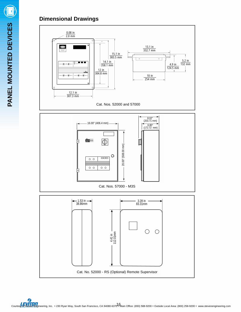
Dimensional Drawings
3.28 in 83.31mm
4.
41 in
11
2.01
mm
1.53 in 38.86mm
Cat. Nos. 52000 and 57000
Cat. No. 52000 - RS (Optional) Remote Supervisor
20.0
0" (5
08.0
0 m
m)
®
6.80" (172.72 mm)
8.02" (203.71 mm)
16.00" (406.4 mm)
Cat. Nos. 57000 - M3S
0.08 in2.0 mm
14.1 in358.1 mm
12 in304.8 mm
12.1 in307.3 mm
15.1 in383.5 mm
5.2 in132 mm4.9 in
124.5 mm
13.1 in332.7 mm
10 in254 mm
Courtesy of Steven Engineering, Inc. ! 230 Ryan Way, South San Francisco, CA 94080-6370 ! Main Office: (650) 588-9200 ! Outside Local Area: (800) 258-9200 ! www.stevenengineering.com
PAN
EL
MO
UN
TE
D D
EV
ICE
S
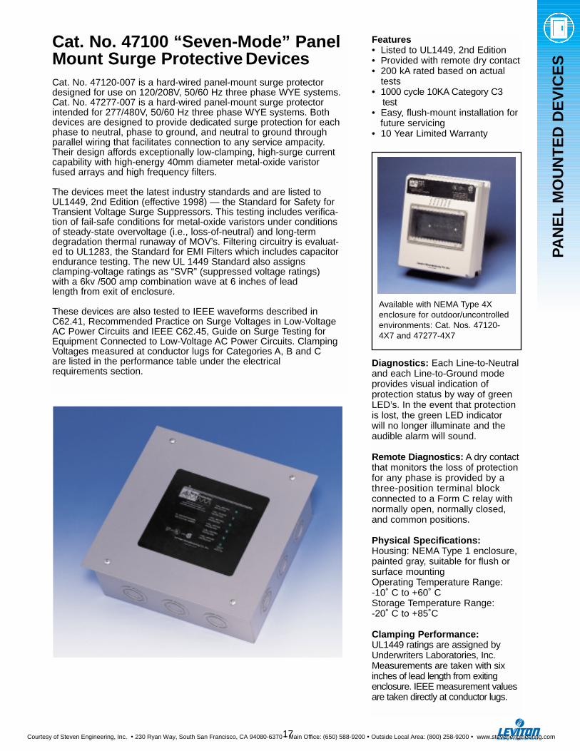
Cat. No. 47100 “Seven-Mode” PanelMount Surge Protective DevicesCat. No. 47120-007 is a hard-wired panel-mount surge protectordesigned for use on 120/208V, 50/60 Hz three phase WYE systems.Cat. No. 47277-007 is a hard-wired panel-mount surge protectorintended for 277/480V, 50/60 Hz three phase WYE systems. Bothdevices are designed to provide dedicated surge protection for eachphase to neutral, phase to ground, and neutral to ground throughparallel wiring that facilitates connection to any service ampacity.Their design affords exceptionally low-clamping, high-surge currentcapability with high-energy 40mm diameter metal-oxide varistor fused arrays and high frequency filters.
The devices meet the latest industry standards and are listed toUL1449, 2nd Edition (effective 1998) — the Standard for Safety forTransient Voltage Surge Suppressors. This testing includes verifica-tion of fail-safe conditions for metal-oxide varistors under conditionsof steady-state overvoltage (i.e., loss-of-neutral) and long-termdegradation thermal runaway of MOV’s. Filtering circuitry is evaluat-ed to UL1283, the Standard for EMI Filters which includes capacitorendurance testing. The new UL 1449 Standard also assigns clamping-voltage ratings as “SVR” (suppressed voltage ratings) with a 6kv /500 amp combination wave at 6 inches of lead length from exit of enclosure.
These devices are also tested to IEEE waveforms described inC62.41, Recommended Practice on Surge Voltages in Low-VoltageAC Power Circuits and IEEE C62.45, Guide on Surge Testing forEquipment Connected to Low-Voltage AC Power Circuits. ClampingVoltages measured at conductor lugs for Categories A, B and C are listed in the performance table under the electrical requirements section.
Features• Listed to UL1449, 2nd Edition • Provided with remote dry contact• 200 kA rated based on actual
tests• 1000 cycle 10KA Category C3
test• Easy, flush-mount installation for
future servicing• 10 Year Limited Warranty
Diagnostics: Each Line-to-Neutraland each Line-to-Ground modeprovides visual indication ofprotection status by way of greenLED’s. In the event that protectionis lost, the green LED indicator will no longer illuminate and theaudible alarm will sound.
Remote Diagnostics: A dry contactthat monitors the loss of protectionfor any phase is provided by athree-position terminal block connected to a Form C relay withnormally open, normally closed,and common positions.
Physical Specifications:Housing: NEMA Type 1 enclosure,painted gray, suitable for flush orsurface mountingOperating Temperature Range:-10˚ C to +60˚ CStorage Temperature Range:-20˚ C to +85˚C
Clamping Performance:UL1449 ratings are assigned byUnderwriters Laboratories, Inc.Measurements are taken with sixinches of lead length from exitingenclosure. IEEE measurement valuesare taken directly at conductor lugs.
17
Available with NEMA Type 4Xenclosure for outdoor/uncontrolledenvironments: Cat. Nos. 47120-4X7 and 47277-4X7
Courtesy of Steven Engineering, Inc. ! 230 Ryan Way, South San Francisco, CA 94080-6370 ! Main Office: (650) 588-9200 ! Outside Local Area: (800) 258-9200 ! www.stevenengineering.com
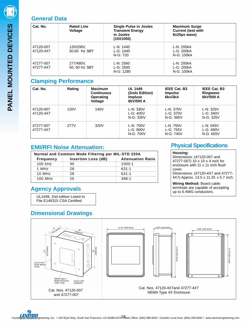
Clamping Performance
EMI/RFI Noise Attenuation:Normal and Common Mode Filtering per MIL-STD 220A
Frequency Insertion Loss (dB) Attenuation Ratio100 kHz 30 1000:11 MHz 28 631:110 MHz 28 631:1100 MHz 25 398:1
Cat. No. Rated Line Single Pulse in Joules Maximum Surge Voltage Transient Energy Current (test with
in Joules 8x20µs wave)(10X1000)
47120-007 120/208V, L-N: 1440 L-N: 200kA47120-4X7 50,60 Hz 3ØY L-G: 1440 L-G: 200kA
N-G: 720 N-G: 100kA
47277-007 277/480V, L-N: 2560 L-N: 200kA47277-4X7 50, 60 Hz 3ØY L-G: 2560 L-G: 200kA
N-G: 1280 N-G: 100kA
General Data
4"
(101.6mm)10"
(254mm)
10"
11"
(279
.4m
m)
(254
mm
)
Green LEDIndicators
NEMA Type 1Metal EnclosureColor: Gray
11x11 InchFlush MountCover
Cat. No. Rating Maximum UL 1449 IEEE Cat. B3 IEEE Cat. B3Continuous (2nds Edition) Impulse RingwaveOperating Impluse 6kv/3kA 6kV/500 AVoltage 6kV/500 A
47120-007 120V 140V L-N: 330V L-N: 370V L-N: 325V47120-4X7 L-G: 400V L-G: 370V L-G: 340V
N-G: 330V N-G: 390V N-G: 325V
47277-007 277V 320V L-N: 700V L-N :750V L-N: 545V47277-4X7 L-G: 800V L-G: 755V L-G: 690V
N-G: 700V N-G: 740V N-G: 655V
Physical Specifications
Agency Approvals
Housing:Dimensions: (47120-007 and47277-007) 10 x 10 x 4 inch forenclosure with 11 x 11 inch flushcover.Dimensions: (47120-4X7 and 47277-4X7) Approx. 13.5 x 11.25 x 5.7 inch.
Wiring Method: Board cable terminals are capable of acceptingup to 6 AWG conductors.
UL1449, 2nd edition Listed to File E146315 CSA Certified
Dimensional Drawings
PAN
EL
MO
UN
TE
D D
EV
ICE
S
18
Cat. Nos. 47120-007and 47277-007
Cat. Nos. 47120-4X7and 47277-4X7 NEMA Type 4X Enclosure
11.25" (285.8mm)8.00" (203.2mm)
5.69" (144.5mm)
13.50"(342.9mm
)
12.76"(324.1mm
)
Courtesy of Steven Engineering, Inc. ! 230 Ryan Way, South San Francisco, CA 94080-6370 ! Main Office: (650) 588-9200 ! Outside Local Area: (800) 258-9200 ! www.stevenengineering.com
PAN
EL
MO
UN
TE
D D
EV
ICE
S
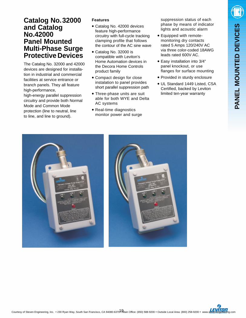
Catalog No.32000and CatalogNo.42000 Panel MountedMulti-Phase SurgeProtective DevicesThe Catalog No. 32000 and 42000devices are designed for installa-tion in industrial and commercialfacilities at service entrance orbranch panels. They all featurehigh-performance, high-energy parallel suppressioncircuitry and provide both NormalMode and Common Mode protection (line to neutral, line to line, and line to ground).
Features
• Catalog No. 42000 devices feature high-performance circuitry with full-cycle tracking clamping profile that follows the contour of the AC sine wave
• Catalog No. 32000 is compatible with Leviton’s Home Automation devices in the Decora Home Controls product family
• Compact design for close instalation to panel provides short parallel suppression path
• Three-phase units are suitable for both WYE and Delta AC systems
• Real-time diagnostics monitor power and surge
suppression status of each phase by means of indicator lights and acoustic alarm
• Equipped with remote-monitoring dry contactsrated 5 Amps 120/240V AC via three color-coded 18AWGleads rated 600V AC.
• Easy installation into 3/4” panel knockout, or use flanges for surface mounting
• Provided in sturdy enclosure
• UL Standard 1449 Listed, CSACertified, backed by Levitonlimited ten-year warranty
19
Courtesy of Steven Engineering, Inc. ! 230 Ryan Way, South San Francisco, CA 94080-6370 ! Main Office: (650) 588-9200 ! Outside Local Area: (800) 258-9200 ! www.stevenengineering.com
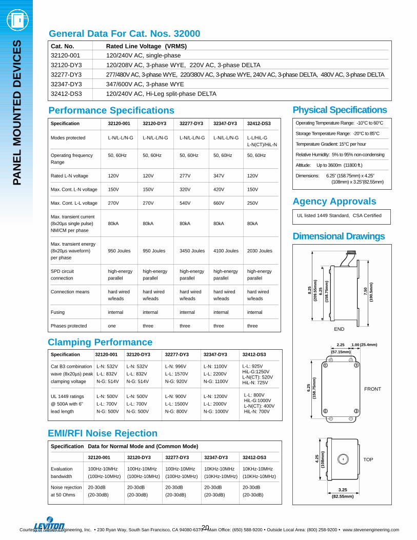
Specification 32120-001 32120-DY3 32277-DY3 32347-DY3 32412-DS3
Modes protected L-N/L-L/N-G L-N/L-L/N-G L-N/L-L/N-G L-N/L-L/N-G L-L/HiL-G L-N(CT)/HiL-N
Operating frequency 50, 60Hz 50, 60Hz 50, 60Hz 50, 60Hz 50, 60HzRange
Rated L-N voltage 120V 120V 277V 347V 120V
Max. Cont. L-N voltage 150V 150V 320V 420V 150V
Max. Cont. L-L voltage 270V 270V 540V 660V 250V
Max. transient current(8x20µs single pulse) 80kA 80kA 80kA 80kA 80kANM/CM per phase
Max. transient energy(8x20µs waveform) 950 Joules 950 Joules 3450 Joules 4100 Joules 2030 Joulesper phase
SPD circuit high-energy high-energy high-energy high-energy high-energyconnection parallel parallel parallel parallel parallel
Connection means hard wired hard wired hard wired hard wired hard wiredw/leads w/leads w/leads w/leads w/leads
Fusing internal internal internal internal internal
Phases protected one three three three three
General Data For Cat. Nos. 32000
Performance Specifications
Clamping Performance
EMI/RFI Noise Rejection
Cat. No. Rated Line Voltage (VRMS)
32120-001 120/240V AC, single-phase
32120-DY3 120/208V AC, 3-phase WYE, 220V AC, 3-phase DELTA
32277-DY3 277/480V AC, 3-phase WYE, 220/380V AC, 3-phase WYE, 240V AC, 3-phase DELTA, 480V AC, 3-phase DELTA
32347-DY3 347/600V AC, 3-phase WYE
32412-DS3 120/240V AC, Hi-Leg split-phase DELTA
Specification 32120-001 32120-DY3 32277-DY3 32347-DY3 32412-DS3
Cat B3 combination L-N: 532V L-N: 532V L-N: 996V L-N: 1100V
wave (8x20µs) peak L-L: 832V L-L: 832V L-L: 1570V L-L: 2200V
clamping voltage N-G: 514V N-G: 514V N-G: 920V N-G: 1100V
UL 1449 ratings L-N: 500V L-N: 500V L-N: 900V L-N: 1200V
@ 500A with 6” L-L: 700V L-L: 700V L-L: 1500V L-L: 2000V
lead length N-G: 500V N-G: 500V N-G: 800V N-G: 1000V
Specification Data for Normal Mode and (Common Mode)
32120-001 32120-DY3 32277-DY3 32347-DY3 32412-DS3
Evaluation 100Hz-10MHz 100Hz-10MHz 100Hz-10MHz 10KHz-10MHz 10KHz-10MHz
bandwidth (100Hz-10MHz) (100Hz-10MHz) (100Hz-10MHz) (10KHz-10MHz) (10KHz-10MHz)
Noise rejection 20-30dB 20-30dB 20-30dB 20-30dB 20-30dB
at 50 Ohms (20-30dB) (20-30dB) (20-30dB) (20-30dB) (20-30dB)
6.25
2.25 1.00
(158
.75m
m)
(57.15mm)
(25.4mm)
7.50
6.258.25
(209
.55m
m)
(158
.75m
m)
(190
.5m
m)
Physical Specifications
Agency Approvals
Dimensional Drawings
Operating Temperature Range: -10°C to 60°C
Storage Temperature Range: -20°C to 85°C
Temperature Gradient: 15°C per hour
Relative Humidity: 5% to 95% non-condensing
Altitude: Up to 3600m (11800 ft.)
Dimensions: 6.25” (158.75mm) x 4.25” (108mm) x 3.25”(82.55mm)
UL listed 1449 Standard, CSA Certified
FRONT
TOP
END
L-L: 925VHiL-G:1250VL-N(CT): 520VHiL-N: 725V
L-L: 800VHiL-G:1000VL-N(CT): 400VHiL-N: 700V
4.25
3.25
(108
mm
)
(82.55mm)
PAN
EL
MO
UN
TE
D D
EV
ICE
S
20
Courtesy of Steven Engineering, Inc. ! 230 Ryan Way, South San Francisco, CA 94080-6370 ! Main Office: (650) 588-9200 ! Outside Local Area: (800) 258-9200 ! www.stevenengineering.com
21
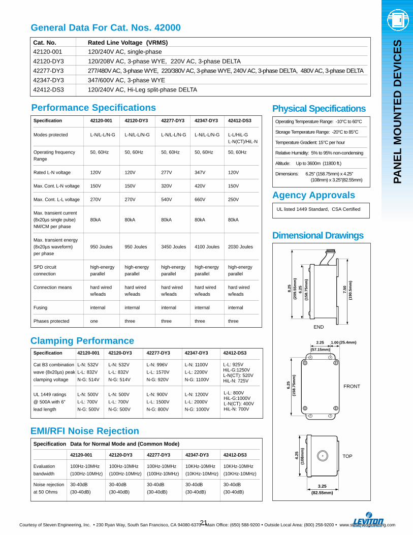
Physical Specifications
Agency Approvals
Operating Temperature Range: -10°C to 60°C
Storage Temperature Range: -20°C to 85°C
Temperature Gradient: 15°C per hour
Relative Humidity: 5% to 95% non-condensing
Altitude: Up to 3600m (11800 ft.)
Dimensions: 6.25” (158.75mm) x 4.25” (108mm) x 3.25”(82.55mm)
UL listed 1449 Standard, CSA Certified
Cat. No. Rated Line Voltage (VRMS)
42120-001 120/240V AC, single-phase
42120-DY3 120/208V AC, 3-phase WYE, 220V AC, 3-phase DELTA
42277-DY3 277/480V AC, 3-phase WYE, 220/380V AC, 3-phase WYE, 240V AC, 3-phase DELTA, 480V AC, 3-phase DELTA
42347-DY3 347/600V AC, 3-phase WYE
42412-DS3 120/240V AC, Hi-Leg split-phase DELTA
General Data For Cat. Nos. 42000
Specification 42120-001 42120-DY3 42277-DY3 42347-DY3 42412-DS3
Modes protected L-N/L-L/N-G L-N/L-L/N-G L-N/L-L/N-G L-N/L-L/N-G L-L/HiL-G L-N(CT)/HiL-N
Operating frequency 50, 60Hz 50, 60Hz 50, 60Hz 50, 60Hz 50, 60HzRange
Rated L-N voltage 120V 120V 277V 347V 120V
Max. Cont. L-N voltage 150V 150V 320V 420V 150V
Max. Cont. L-L voltage 270V 270V 540V 660V 250V
Max. transient current(8x20µs single pulse) 80kA 80kA 80kA 80kA 80kANM/CM per phase
Max. transient energy(8x20µs waveform) 950 Joules 950 Joules 3450 Joules 4100 Joules 2030 Joulesper phase
SPD circuit high-energy high-energy high-energy high-energy high-energyconnection parallel parallel parallel parallel parallel
Connection means hard wired hard wired hard wired hard wired hard wiredw/leads w/leads w/leads w/leads w/leads
Fusing internal internal internal internal internal
Phases protected one three three three three
Performance Specifications
Clamping Performance
EMI/RFI Noise Rejection
Specification 42120-001 42120-DY3 42277-DY3 42347-DY3 42412-DS3
Cat B3 combination L-N: 532V L-N: 532V L-N: 996V L-N: 1100V
wave (8x20µs) peak L-L: 832V L-L: 832V L-L: 1570V L-L: 2200V
clamping voltage N-G: 514V N-G: 514V N-G: 920V N-G: 1100V
UL 1449 ratings L-N: 500V L-N: 500V L-N: 900V L-N: 1200V
@ 500A with 6” L-L: 700V L-L: 700V L-L: 1500V L-L: 2000V
lead length N-G: 500V N-G: 500V N-G: 800V N-G: 1000V
Specification Data for Normal Mode and (Common Mode)
42120-001 42120-DY3 42277-DY3 42347-DY3 42412-DS3
Evaluation 100Hz-10MHz 100Hz-10MHz 100Hz-10MHz 10KHz-10MHz 10KHz-10MHz
bandwidth (100Hz-10MHz) (100Hz-10MHz) (100Hz-10MHz) (10KHz-10MHz) (10KHz-10MHz)
Noise rejection 30-40dB 30-40dB 30-40dB 30-40dB 30-40dB
at 50 Ohms (30-40dB) (30-40dB) (30-40dB) (30-40dB) (30-40dB)
L-L: 925VHiL-G:1250VL-N(CT): 520VHiL-N: 725V
L-L: 800VHiL-G:1000VL-N(CT): 400VHiL-N: 700V
PAN
EL
MO
UN
TE
D D
EV
ICE
S
6.25
2.25 1.00
(158
.75m
m)
(57.15mm)
(25.4mm)7.
50
6.258.25
(209
.55m
m)
(158
.75m
m)
(190
.5m
m)
FRONT
TOP
END
4.25
3.25
(108
mm
)
(82.55mm)
Dimensional Drawings
Courtesy of Steven Engineering, Inc. ! 230 Ryan Way, South San Francisco, CA 94080-6370 ! Main Office: (650) 588-9200 ! Outside Local Area: (800) 258-9200 ! www.stevenengineering.com
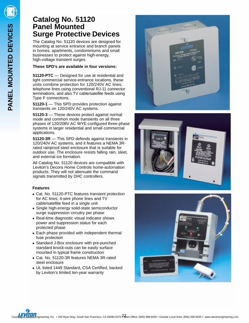
Catalog No. 51120Panel Mounted Surge Protective DevicesThe Catalog No. 51120 devices are designed formounting at service entrance and branch panels in homes, apartments, condominiums and small businesses to protect against high-energy, high-voltage transient surges.
These SPD’s are available in four versions:
51120-PTC — Designed for use at residential andlight commercial service-entrance locations, theseunits combine protection for 120/240V AC lines, telephone lines using conventional RJ-11 connectorterminations, and also TV cable/satellite feeds usingType F connections.
51120-1 — This SPD provides protection againsttransients on 120/240V AC systems.
51120-3 — These devices protect against normalmode and common mode transients on all threephases of 120/208V AC WYE-configured three-phasesystems in larger residential and small commercialapplications.
51120-3R — This SPD defends against transients in120/240V AC systems, and it features a NEMA 3R-rated rainproof steel enclosure that is suitable for outdoor use. The enclosure resists falling rain, sleet,and external ice formation.
All Catalog No. 51120 devices are compatible withLeviton’s Decora Home Controls home-automationproducts. They will not attenuate the command signals transmitted by DHC controllers.
Features
• Cat. No. 51120-PTC features transient protection for AC lines, 4-wire phone lines and TV cable/satellite feed in a single unit
• Single high-energy solid-state semiconductor surge suppression circuitry per phase
• Real-time diagnostic visual indicator shows power and suppression status for each protected phase
• Each phase provided with independent thermal fuse protection
• Standard J-Box enclosure with pre-punched standard knock-outs can be easily surface mounted in typical frame construction
• Cat. No. 51120-3R features NEMA 3R-rated steel enclosure
• UL listed 1449 Standard, CSA Certified, backed by Leviton’s limited ten-year warranty
22
PAN
EL
MO
UN
TE
D D
EV
ICE
S
Courtesy of Steven Engineering, Inc. ! 230 Ryan Way, South San Francisco, CA 94080-6370 ! Main Office: (650) 588-9200 ! Outside Local Area: (800) 258-9200 ! www.stevenengineering.com

PAN
EL
MO
UN
TE
D D
EV
ICE
S
23
General Data
Dimensional Drawings
Cat. No. Rated Line Voltage (VRMS)
51120-1 120/240V AC, single-phase
51120-3 120/208V AC, 3-phase WYE
51120-3R 120/240V AC, single-phaseNEMA 3R Enclosure
51120-PTC 120/240V AC, single-phaseRJ-11 telephone (2-line)Type F connector/CATV-Satellite
Specification 51120-1 51120-3 51120-3R 51120-PTC
Rated Line voltage 120V 120V 120/208V 120V
Max.Cont. Line voltage 150V 150V 180V AC: 150VTel.: 90V DCCATV:10V DC
Operational frequency 50,60Hz 50,60Hz 50,60Hz 50,60HzRange
Performance Specifications
Clamping PerformanceSpecification 51120-1 51120-3 51120-3R 51120-PTC
Cat B3 combination wave (8x20µs) peak 480V 480V 640V AC:480Vclamping voltage
Max. single-pulse AC:80,000Atransient current 50,000A 50,000A 50,000A Tel.:[email protected](8x20µs, Amps peak) CATV: 2KA
Rated single-pulsetransient energy 950J 950J 950J AC: 950J(10x1000µs Joules)
UL1449 Rating (L-N) 500V 500V 800V AC: 500VTel.: 220VCATV: 25V
Physical Specifications
Agency Approvals
Operating Temperature Range: -10°C to 60°C
Storage Temperature Range: -20°C to 85°C
Dimensions Overall: 7.0”(177.8mm) x7.0”51120-1, -3 (177.8mm) x4.06” (103.1mm)
NEMA 3R Enclosure: 8.0”(203.2) x 6”(152.4) x 4”(101.6)and 51120-PTC
Wiring Means: Screw Terminals for 14AWG to 10AWG conductors
UL listed 1449 Standard, CSA Certified
6.00 (152.4mm)
7.00
(17
7.8m
m)
6.00
(15
2.4m
m)
7.00 (177.8mm)
6.00
RE
F. (
152.
4mm
)
4.06 (103.12mm)
4.00 (101.6mm)
4.45 (113.03mm)
6.00 (152.4mm)
2.25 (57.15)
6.50 (165.1mm)
Ø 0
.281
(7.1
4mm
)
5.88
(14
9.35
mm
) (
26.9
2mm
)1.
06
Cat. Nos. 51120-1,-3
7.506.25
8.25
6.25
2.25 1.00
(209
.55m
m)
(158
.75m
m)
(190
.5m
m)
(158
.75m
m)
(57.15mm)
(25.4mm)
4.25(107.95mm)
SIDE
FRONT
Cat. No. 51120-3R
Cat. No. 51120-PTC
Courtesy of Steven Engineering, Inc. ! 230 Ryan Way, South San Francisco, CA 94080-6370 ! Main Office: (650) 588-9200 ! Outside Local Area: (800) 258-9200 ! www.stevenengineering.com

The 50240-MSA offers a reliable,economical way to protect againstexternal power surges that enter ahome through the electrical serviceentrance.This unit is ideal for utilitieslooking to provide their customerswith expanded, value-added servicessuch as surge protection. All that’srequired is a fast, simple installationby the appropriate utility servicepersonnel. There’s no inconvenienceto customers or disruption of service.The device can be offered as astand-alone product, or as part of awhole-house program that includesdownline and communication surgeprotection.
Features
• Use of a single, large 53 mm MOV perline (Line 1-Neutral, Line 2- Neutral andand Line to Line) provides a higherenergy capacity than multiple small MOV configurations where the protec-tion is only as good as the weakest MOV in the chain
• Surge Arrester performance tested to IEEE C62.11 (10,000 Amps/4X10 µs)and IEEE C62.41 and C62.45 Category C standards
• UL Listed Surge Arrester (465V discharge voltage @1500 Amps)
• Rated for 65,000 peak Amps maxi-mum surge current
• Nominal clamping voltage per line: 800V (per UL 1449)
• Diagnostic LED’s: green indicates surge protection is active; red indicatesprotection is no longer active
• Designed for 120/240 volt single-phase ringless or ring-type meters
• Rugged housing constructed of high-impact, non-conductive fiberglass-reinforced polycarbonate
• Available in popular jaw configurations, featuring spring-loaded, high pressure copper-plated contacts for maximum conductivity
• 200 Amp rated current carrying capacity rating per UL 414 for specific meter-socket socket bases (consult factory for socket types)
• Backed by Leviton’s Limited 10-Year Warranty
Cat. No. 50240-MSAMeter Socket Surge Arrester AdapterA Great First Line of Defense for Utility Company Customers Helps Utilities Protect Their Customers Against External Power SurgesEntering Through the Electrical Service Entrance
L
L Indicates suggested placement ofLeviton SPD product. Other solutions mayalso apply. Attention should be paid toavailable options with panel mounted SPD.
L
L
L
METER
Cat. No. 50240-MSAMETER SOCKET
SURGE ADAPTER120/240
1-PHASE 200A
MICROWAVEREF.
20 AMP
FURNACESTEREOHOME
ENTERTAIN-MENT
CENTERDRYER WASHER
20 AMP
VCR
SATELLITECONTROLLER
TO DISHCOAXCABLESECURITY
SYSTEMTO POINTCONTACTS
HOMEOFFICE
LSATELLITE DISHCOMMUNICATION SPD
TELEPHONE LINE
POWERCONTROL CENTER
SPDPHONE LINE
SPD
COAXCABLE
PANEL-MOUNT SPD
L
L
PC
RECEPTACLE SPD
RECEPTACLESPD
TV
BIGSCREEN
TV
L L
RECEPTACLE OR PLUG-IN SPD'S
L
L
PLUG-IN SPDPLUG-STRIP SPD
LL
Example of Leviton's Whole-HouseSurge Protection Network
CATVCOMMUNICATION SPD
24
PAN
EL
MO
UN
TE
D D
EV
ICE
S
Courtesy of Steven Engineering, Inc. ! 230 Ryan Way, South San Francisco, CA 94080-6370 ! Main Office: (650) 588-9200 ! Outside Local Area: (800) 258-9200 ! www.stevenengineering.com
WIR
ED
-IN
DE
VIC
ES
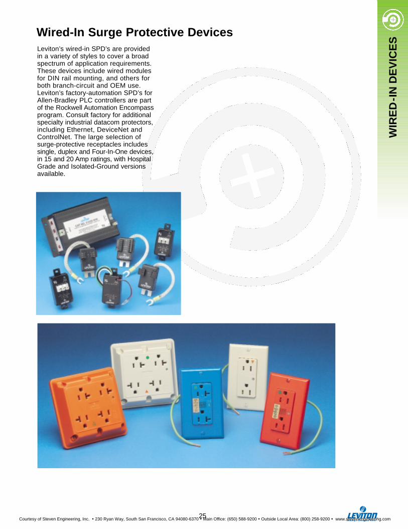
Leviton’s wired-in SPD’s are provided in a variety of styles to cover a broadspectrum of application requirements.These devices include wired modulesfor DIN rail mounting, and others forboth branch-circuit and OEM use.Leviton’s factory-automation SPD’s forAllen-Bradley PLC controllers are part of the Rockwell Automation Encompassprogram. Consult factory for additionalspecialty industrial datacom protectors,including Ethernet, DeviceNet andControlNet. The large selection ofsurge-protective receptacles includessingle, duplex and Four-In-One devices,in 15 and 20 Amp ratings, with HospitalGrade and Isolated-Ground versionsavailable.
Wired-In Surge Protective Devices
25
Courtesy of Steven Engineering, Inc. ! 230 Ryan Way, South San Francisco, CA 94080-6370 ! Main Office: (650) 588-9200 ! Outside Local Area: (800) 258-9200 ! www.stevenengineering.com
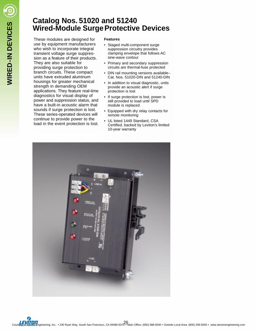
These modules are designed foruse by equipment manufacturerswho wish to incorporate integraltransient voltage surge suppres-sion as a feature of their products.They are also suitable for providing surge protection tobranch circuits. These compactunits have extruded aluminumhousings for greater mechanicalstrength in demanding OEM applications. They feature real-timediagnostics for visual display ofpower and suppression status, andhave a built-in acoustic alarm thatsounds if surge protection is lost.These series-operated devices willcontinue to provide power to theload in the event protection is lost.
Features
• Staged multi-component surge suppression circuitry provides clamping envelope that follows AC sine-wave contour
• Primary and secondary suppression circuits are thermal-fuse protected
• DIN rail mounting versions available–Cat. Nos. 51020-DIN and 51240-DIN
• In addition to visual diagnostic, units provide an acoustic alert if surge protection is lost
• If surge protection is lost, power is still provided to load until SPD module is replaced
• Equipped with dry relay contacts for remote monitoring
• UL listed 1449 Standard, CSACertified, backed by Leviton’s limited 10-year warranty
Catalog Nos. 51020 and 51240Wired-Module SurgeProtective Devices
WIR
ED
-IN
DE
VIC
ES
26
Courtesy of Steven Engineering, Inc. ! 230 Ryan Way, South San Francisco, CA 94080-6370 ! Main Office: (650) 588-9200 ! Outside Local Area: (800) 258-9200 ! www.stevenengineering.com
WIR
ED
-IN
DE
VIC
ES
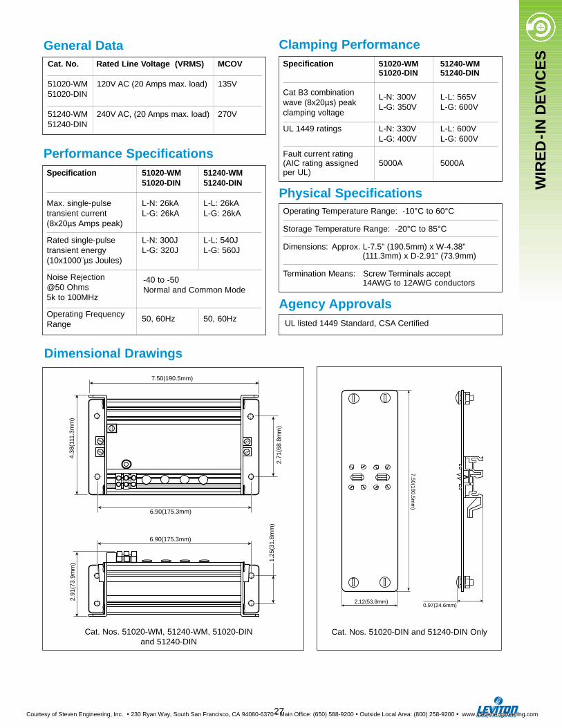
General DataCat. No. Rated Line Voltage (VRMS) MCOV
51020-WM 120V AC (20 Amps max. load) 135V51020-DIN
51240-WM 240V AC, (20 Amps max. load) 270V51240-DIN
Specification 51020-WM 51240-WM51020-DIN 51240-DIN
Max. single-pulse L-N: 26kA L-L: 26kAtransient current L-G: 26kA L-G: 26kA(8x20µs Amps peak)
Rated single-pulse L-N: 300J L-L: 540Jtransient energy L-G: 320J L-G: 560J(10x1000¨µs Joules)
Noise Rejection@50 Ohms5k to 100MHz
Operating Frequency 50, 60Hz 50, 60HzRange
Performance Specifications
Clamping PerformanceSpecification 51020-WM 51240-WM
51020-DIN 51240-DIN
Cat B3 combinationwave (8x20µs) peak
L-N: 300V L-L: 565V
clamping voltageL-G: 350V L-G: 600V
UL 1449 ratings L-N: 330V L-L: 600VL-G: 400V L-G: 600V
Fault current rating(AIC rating assigned 5000A 5000Aper UL)
Physical Specifications
Agency Approvals
Operating Temperature Range: -10°C to 60°C
Storage Temperature Range: -20°C to 85°C
Dimensions: Approx. L-7.5” (190.5mm) x W-4.38” (111.3mm) x D-2.91” (73.9mm)
Termination Means: Screw Terminals accept14AWG to 12AWG conductors
UL listed 1449 Standard, CSA Certified
6.90(175.3mm)
2.91
(73.
9mm
) 1.25
(31.
8mm
)
6.90(175.3mm)
7.50(190.5mm)
4.38
(111
.3m
m)
2.71
(68.
8mm
)
7.50(190.5mm
)
2.12(53.8mm)0.97(24.6mm)
-40 to -50Normal and Common Mode
27
Dimensional Drawings
Cat. Nos. 51020-WM, 51240-WM, 51020-DINand 51240-DIN
Cat. Nos. 51020-DIN and 51240-DIN Only
Courtesy of Steven Engineering, Inc. ! 230 Ryan Way, South San Francisco, CA 94080-6370 ! Main Office: (650) 588-9200 ! Outside Local Area: (800) 258-9200 ! www.stevenengineering.com
WIR
ED
-IN
DE
VIC
ES
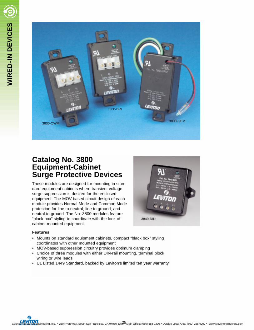
Catalog No. 3800 Equipment-Cabinet Surge Protective DevicesThese modules are designed for mounting in stan-dard equipment cabinets where transient voltagesurge suppression is desired for the enclosedequipment. The MOV-based circuit design of eachmodule provides Normal Mode and Common Modeprotection for line to neutral, line to ground, andneutral to ground. The No. 3800 modules feature“black box” styling to coordinate with the look ofcabinet-mounted equipment.
Features• Mounts on standard equipment cabinets, compact “black box” styling
coordinates with other mounted equipment• MOV-based suppression circuitry provides optimum clamping• Choice of three modules with either DIN-rail mounting, terminal block
wiring or wire leads• UL Listed 1449 Standard, backed by Leviton’s limited ten year warranty
28
3800-OWM3800-OEM
3800-DIN
3840-DIN
Courtesy of Steven Engineering, Inc. ! 230 Ryan Way, South San Francisco, CA 94080-6370 ! Main Office: (650) 588-9200 ! Outside Local Area: (800) 258-9200 ! www.stevenengineering.com
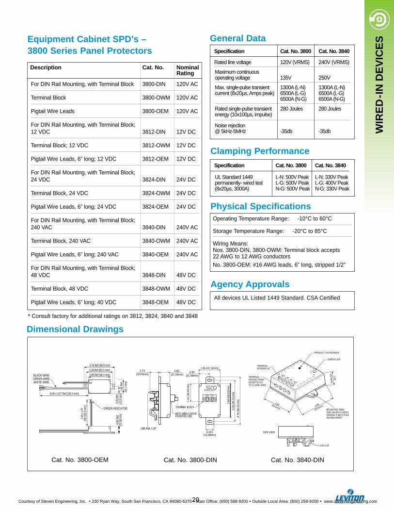
Description Cat. No. NominalRating
For DIN Rail Mounting, with Terminal Block 3800-DIN 120V AC
Terminal Block 3800-OWM 120V AC
Pigtail Wire Leads 3800-OEM 120V AC
For DIN Rail Mounting, with Terminal Block; 12 VDC 3812-DIN 12V DC
Terminal Block; 12 VDC 3812-OWM 12V DC
Pigtail Wire Leads, 6” long; 12 VDC 3812-OEM 12V DC
For DIN Rail Mounting, with Terminal Block; 24 VDC 3824-DIN 24V DC
Terminal Block, 24 VDC 3824-OWM 24V DC
Pigtail Wire Leads, 6” long; 24 VDC 3824-OEM 24V DC
For DIN Rail Mounting, with Terminal Block; 240 VAC 3840-DIN 240V AC
Terminal Block, 240 VAC 3840-OWM 240V AC
Pigtail Wire Leads, 6” long; 240 VAC 3840-OEM 240V AC
For DIN Rail Mounting, with Terminal Block; 48 VDC 3848-DIN 48V DC
Terminal Block, 48 VDC 3848-OWM 48V DC
Pigtail Wire Leads, 6” long; 40 VDC 3848-OEM 48V DC
WIR
ED
-IN
DE
VIC
ESEquipment Cabinet SPD’s –
3800 Series Panel Protectors
Dimensional Drawings
Cat. No. 3800-OEM
29
General Data
Physical Specifications
Agency Approvals
Operating Temperature Range: -10°C to 60°C
Storage Temperature Range: -20°C to 85°C
Wiring Means:Nos. 3800-DIN, 3800-OWM: Terminal block accepts 22 AWG to 12 AWG conductorsNo. 3800-OEM: #16 AWG leads, 6” long, stripped 1/2”
All devices UL Listed 1449 Standard. CSA Certified
Specification Cat. No. 3800 Cat. No. 3840
Rated line voltage 120V (VRMS) 240V (VRMS)
Maximum continuousoperating voltage 135V 250V
Max. single-pulse transient 1300A (L-N) 1300A (L-N)current (8x20µs, Amps peak) 6500A (L-G) 6500A (L-G)
6500A (N-G) 6500A (N-G)
Rated single-pulse transient 280 Joules 280 Joulesenergy (10x100µs, impulse)
Noise rejection@ 5kHz-5MHz -35db -35db
Clamping PerformanceSpecification Cat. No. 3800 Cat. No. 3840
UL Standard 1449 L-N: 500V Peak L-N: 330V Peakpermanently- wired test L-G: 500V Peak L-G: 400V Peak(8x20µs, 3000A) N-G: 500V Peak N-G: 330V Peak
0.83
Ref
(21.
0 m
m)
1.66
Ref
(42.
1 m
m)
3.25
± 1
/4"
Ref
(82.
5 m
m)
0.85
Ref
(21.
59 m
m)
2.69 Ref (68.3 mm)
6.00 ± 1/2" Ref (152.4 mm)
3.78 Ref (96.0 mm)
3.28 Ref (83.3 mm)
BLACK WIREGREEN WIREWHITE WIRE
GREEN INDICATOR
LIGHT ONSURGE
PROTECTED
1.66 (42.16mm)0.83
(21.08mm)
2.69
(68.
33m
m)
3.28
(83.
31m
m)
3.78
(96.
01m
m)
0.625(15.88mm)
TERMINAL BLOCK
1.41
(35.
81m
m)
NOTE: WIRES ENTERFROM THIS SIDE
0.73(18.54mm)
0.85 (21.59mm)
DIN RAIL CLIP
Cat. No. 3800-DIN
* Consult factory for additional ratings on 3812, 3824, 3840 and 3848
Cat. No. 3840-DIN
L1 N G L2
TERMINALSCREWS (4)
TERMINAL CONNECTIONSACCEPTS #22 TO 12 AWG WIRE
PRODUCT SILKSCREEN
GREEN LED
MOUNTING TABS.ONE ON BOTH SIDES,SPACED 2.90(73.7mm)INCHES APART
1.00
(25.4mm
)
2.99
(75.9mm)2.49(63.2mm)
SIDE VIEW
DIN CLIP
Courtesy of Steven Engineering, Inc. ! 230 Ryan Way, South San Francisco, CA 94080-6370 ! Main Office: (650) 588-9200 ! Outside Local Area: (800) 258-9200 ! www.stevenengineering.com

WIR
ED
-IN
DE
VIC
ES
The Cat. No. 3803-DHP is designedto provide transient voltage surge suppression for programmable logicdevices and other computer-relateddata network products operating on“Blue Hose”* networks. It is compati-ble with Allen Bradley DH, DH+, andRemote I/O networks that are typical-ly connected using Belden cable No.9463, 9184, Allen Bradley 1770-CD,or equivalents (DH and DH+ aretrademarks of the Allen BradleyCorporation). Low clamping voltagesare provided along with the ability towithstand high transient currentsurges that may be encountered byprogrammable logic devices operat-ing in harsh electromagnetic environ-ments or geographic areas wherethere is exposure to the effects oflightning strikes.
Communication Protection ModulesUL 497B Listed Protection for Data Communication Circuits
Features
• Utilizes 3 Pin Compatible (or equiva-lent) communication port connectors
• Provides ground plate for direct con-nection to the 1771 I/O chassis ground stud or pig-tail lead for directconnection to the ground bus as grounding options
• Tested to IEEE C62.36 Standard Test Methods for Surge Protectors Used in Low-Voltage, Data and Communication Signaling Circuits
• Meets UL 497B Protection for Data Communication and Fire Alarm Circuits
• Backed by Leviton’s 10-year Limited Warranty.
Cat. No. 3803-DHPFor Blue Hose Networks
PerformanceMaximum DC Operating Voltage 9.6V DCClamping Voltage 81V (See Note 1)Maximum Surge Current 1kA (See Note 1)Maximum Capacitance L-L: 7.48 pf, L-G: 17.48 pf
Physical SpecificationsOperating Temperature Range -40°C to 60°CStorage Temperature Range -40°C to 90°CRelative Humidity 0 to 95% non-condensingAltitude -1000 ft. to 15000 ft.Dimensions L-3.0” (76.2mm) x W-1.5” (38.1mm)
x H-0.875” (22.23mm) Weight 2.1 oz.Case Material ABS Thermoplastic (See Note 2)Base-Plate Material Brushed BrassColor Black housing with brushed-brass ground plateAgency Approval UL 497B
NOTES:1. Measured at 2kV (1.2 x 50 µs),
1kA (8 x 20 µs).2. ABS is a flame-retardant thermo-
plastic compliant with UL 497B polymeric material test requirements.
3 Pin TerminalConnectors (2)(Included)
3 Pin Headers (2)
BraidedGroundWire
1.51 REF2.26 REF
6.00 REF
0.65".79
REF
Brass TerminalPlate ConnectedTo Ground
Dimensional Drawings
Cat. No. 3803-DHP* Blue Hose is a registered trademark of Belden Corporation.
30
Courtesy of Steven Engineering, Inc. ! 230 Ryan Way, South San Francisco, CA 94080-6370 ! Main Office: (650) 588-9200 ! Outside Local Area: (800) 258-9200 ! www.stevenengineering.com
WIR
ED
-IN
DE
VIC
ES
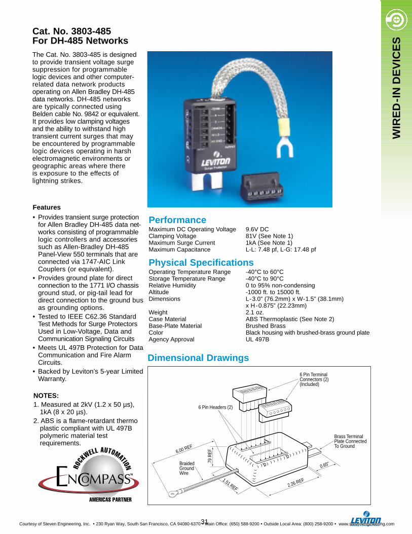
Cat. No. 3803-485For DH-485 NetworksThe Cat. No. 3803-485 is designedto provide transient voltage surgesuppression for programmable logic devices and other computer-related data network products operating on Allen Bradley DH-485data networks. DH-485 networksare typically connected usingBelden cable No. 9842 or equivalent.It provides low clamping voltagesand the ability to withstand hightransient current surges that maybe encountered by programmablelogic devices operating in harshelectromagnetic environments orgeographic areas where there is exposure to the effects oflightning strikes.
NOTES:1. Measured at 2kV (1.2 x 50 µs),
1kA (8 x 20 µs).2. ABS is a flame-retardant thermo
plastic compliant with UL 497B polymeric material test requirements.
31
Features• Provides transient surge protection
for Allen Bradley DH-485 data net-works consisting of programmablelogic controllers and accessoriessuch as Allen-Bradley DH-485Panel-View 550 terminals that areconnected via 1747-AIC LinkCouplers (or equivalent).
• Provides ground plate for directconnection to the 1771 I/O chassisground stud, or pig-tail lead fordirect connection to the ground busas grounding options.
• Tested to IEEE C62.36 StandardTest Methods for Surge ProtectorsUsed in Low-Voltage, Data andCommunication Signaling Circuits
• Meets UL 497B Protection for DataCommunication and Fire AlarmCircuits.
• Backed by Leviton’s 5-year LimitedWarranty.
6 Pin TerminalConnectors (2)(Included)
1.51 REF 2.26 REF
0.65"
Brass TerminalPlate ConnectedTo Ground
.79
REF
BraidedGroundWire
6.00 REF
6 Pin Headers (2)
PerformanceMaximum DC Operating Voltage 9.6V DCClamping Voltage 81V (See Note 1)Maximum Surge Current 1kA (See Note 1)Maximum Capacitance L-L: 7.48 pf, L-G: 17.48 pf
Physical SpecificationsOperating Temperature Range -40°C to 60°CStorage Temperature Range -40°C to 90°CRelative Humidity 0 to 95% non-condensingAltitude -1000 ft. to 15000 ft.Dimensions L-3.0” (76.2mm) x W-1.5” (38.1mm)
x H-0.875” (22.23mm)Weight 2.1 oz.Case Material ABS Thermoplastic (See Note 2)Base-Plate Material Brushed BrassColor Black housing with brushed-brass ground plate Agency Approval UL 497B
Dimensional Drawings
Courtesy of Steven Engineering, Inc. ! 230 Ryan Way, South San Francisco, CA 94080-6370 ! Main Office: (650) 588-9200 ! Outside Local Area: (800) 258-9200 ! www.stevenengineering.com
WIR
ED
-IN
DE
VIC
ES
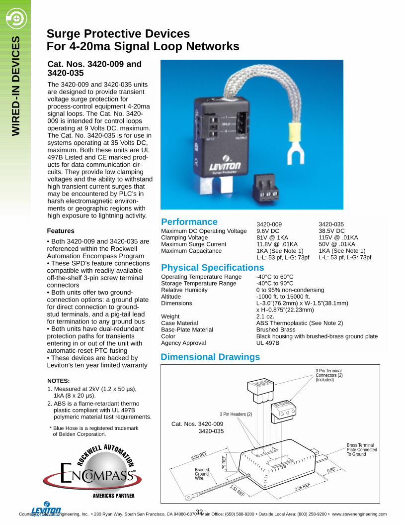
The 3420-009 and 3420-035 unitsare designed to provide transientvoltage surge protection forprocess-control equipment 4-20masignal loops. The Cat. No. 3420-009 is intended for control loopsoperating at 9 Volts DC, maximum.The Cat. No. 3420-035 is for use insystems operating at 35 Volts DC,maximum. Both these units are UL497B Listed and CE marked prod-ucts for data communication cir-cuits. They provide low clampingvoltages and the ability to withstandhigh transient current surges thatmay be encountered by PLC’s inharsh electromagnetic environ-ments or geographic regions withhigh exposure to lightning activity.
Features
• Both 3420-009 and 3420-035 arereferenced within the RockwellAutomation Encompass Program• These SPD’s feature connectionscompatible with readily availableoff-the-shelf 3-pin screw terminalconnectors• Both units offer two ground-connection options: a ground platefor direct connection to ground-stud terminals, and a pig-tail leadfor termination to any ground bus• Both units have dual-redundantprotection paths for transientsentering in or out of the unit withautomatic-reset PTC fusing• These devices are backed byLeviton’s ten year limited warranty
Cat. Nos. 3420-009 and3420-035
PerformanceMaximum DC Operating VoltageClamping VoltageMaximum Surge CurrentMaximum Capacitance
Physical SpecificationsOperating Temperature Range -40°C to 60°CStorage Temperature Range -40°C to 90°CRelative Humidity 0 to 95% non-condensingAltitude -1000 ft. to 15000 ft.Dimensions L-3.0”(76.2mm) x W-1.5”(38.1mm)
x H-0.875”(22.23mm)Weight 2.1 oz.Case Material ABS Thermoplastic (See Note 2)Base-Plate Material Brushed BrassColor Black housing with brushed-brass ground plateAgency Approval UL 497B
NOTES:1. Measured at 2kV (1.2 x 50 µs),
1kA (8 x 20 µs).2. ABS is a flame-retardant thermo
plastic compliant with UL 497B polymeric material test requirements.
3 Pin TerminalConnectors (2)(Included)
3 Pin Headers (2)
BraidedGroundWire
1.51 REF2.26 REF
6.00 REF
0.65".79
REF
Brass TerminalPlate ConnectedTo Ground
Dimensional Drawings
Cat. Nos. 3420-0093420-035* Blue Hose is a registered trademark
of Belden Corporation.
Surge Protective Devices For 4-20ma Signal Loop Networks
3420-0099.6V DC81V @ 1KA11.8V @ .01KA1KA (See Note 1)L-L: 53 pf, L-G: 73pf
3420-03538.5V DC115V @ .01KA50V @ .01KA1KA (See Note 1)L-L: 53 pf, L-G: 73pf
32
Courtesy of Steven Engineering, Inc. ! 230 Ryan Way, South San Francisco, CA 94080-6370 ! Main Office: (650) 588-9200 ! Outside Local Area: (800) 258-9200 ! www.stevenengineering.com
WIR
ED
-IN
DE
VIC
ES
1.7 (43.18mm)
0.937(23.79mm)
2.75
(69
.85m
m)
3.28
(83
.31m
m)
1.60 (40.64mm)
1.312 (33.27mm)
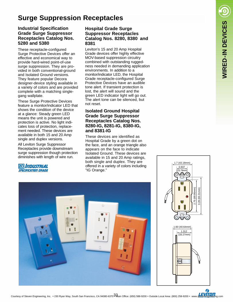
Surge Suppression ReceptaclesIndustrial SpecificationGrade Surge SuppressorReceptacles Catalog Nos.5280 and 5380These receptacle-configuredSurge Protective Devices offer aneffective and economical way toprovide hard-wired point-of-usesurge suppression. They are pro-vided in both conventional-groundand Isolated Ground versions.They feature popular Decoradesigner-device styling available ina variety of colors and are providedcomplete with a matching single-gang wallplate.
These Surge Protective Devicesfeature a monitor/indicator LED thatshows the condition of the deviceat a glance: Steady green LEDmeans the unit is powered and protection is active. No light indi-cates loss of protection, replace-ment needed. These devices areavailable in both 15 and 20 Ampsingle and duplex versions.All Leviton Surge SuppressorReceptacles provide downstreamsurge suppression though protectiondiminishes with length of wire run.
Hospital Grade SurgeSuppressor ReceptaclesCatalog Nos. 8280, 8380 and8381Leviton’s 15 and 20 Amp HospitalGrade devices offer highly effectiveMOV-based suppression circuitry combined with outstanding rugged-ness needed in demanding applicationenvironments. In addition to amonitor/indicator LED, the HospitalGrade receptacle-configured SurgeProtective Devices have an audibletone alert. If transient protection islost, the alert will sound and the green LED indicator light will go out.The alert tone can be silenced, butnot reset.
Isolated Ground HospitalGrade Surge SuppressorReceptacles Catalog Nos. 8280-IG, 8281-IG, 8380-IG,and 8381-IGThese devices are identified asHospital Grade by a green dot on the face, and an orange triangle alsoappears on the face to indicateIsolated Ground. These devices areavailable in 15 and 20 Amp ratings,both single and duplex. They areoffered in a variety of colors including”IG Orange.”
33
Courtesy of Steven Engineering, Inc. ! 230 Ryan Way, South San Francisco, CA 94080-6370 ! Main Office: (650) 588-9200 ! Outside Local Area: (800) 258-9200 ! www.stevenengineering.com
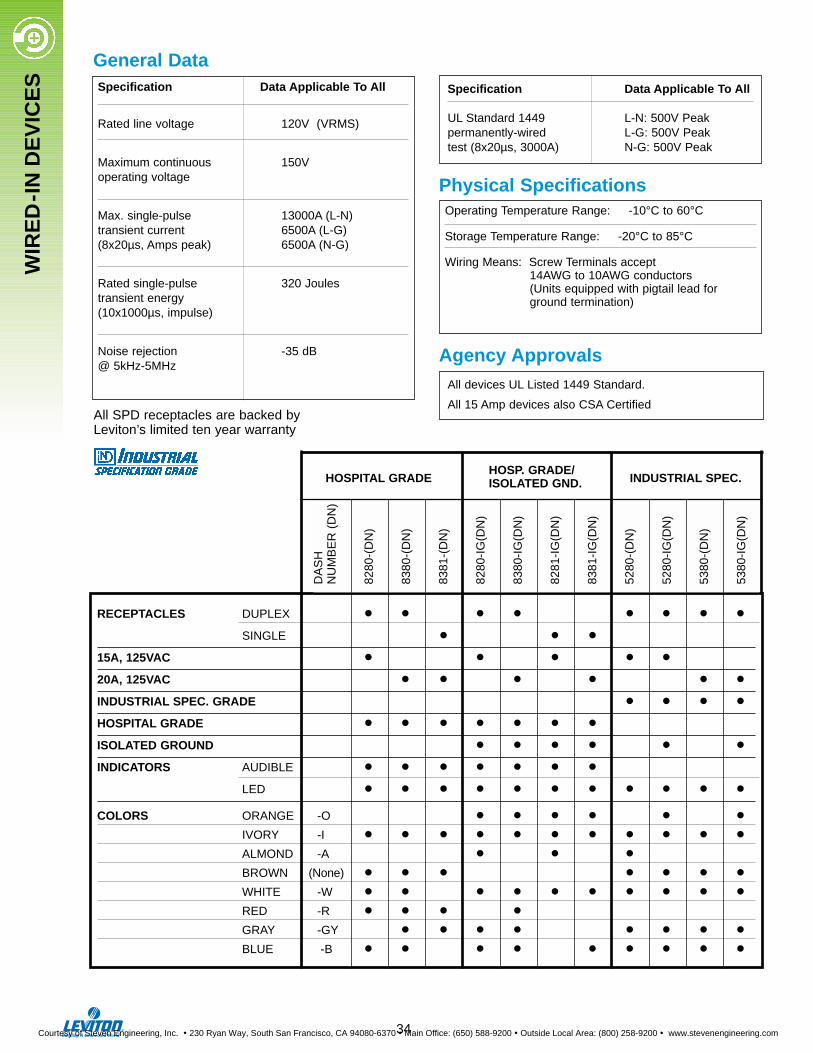
General DataSpecification Data Applicable To All
Rated line voltage 120V (VRMS)
Maximum continuous 150V operating voltage
Max. single-pulse 13000A (L-N)transient current 6500A (L-G)(8x20µs, Amps peak) 6500A (N-G)
Rated single-pulse 320 Joulestransient energy(10x1000µs, impulse)
Noise rejection -35 dB@ 5kHz-5MHz
Physical Specifications
Agency Approvals
Operating Temperature Range: -10°C to 60°C
Storage Temperature Range: -20°C to 85°C
Wiring Means: Screw Terminals accept 14AWG to 10AWG conductors (Units equipped with pigtail lead for ground termination)
All devices UL Listed 1449 Standard.
All 15 Amp devices also CSA Certified
Specification Data Applicable To All
UL Standard 1449 L-N: 500V Peakpermanently-wired L-G: 500V Peaktest (8x20µs, 3000A) N-G: 500V Peak
RECEPTACLES DUPLEX • • • • • • • •SINGLE • • •
15A, 125VAC • • • • •20A, 125VAC • • • • • •INDUSTRIAL SPEC. GRADE • • • •HOSPITAL GRADE • • • • • • •ISOLATED GROUND • • • • • •INDICATORS AUDIBLE • • • • • • •
LED • • • • • • • • • • •COLORS ORANGE -O • • • • • •
IVORY -I • • • • • • • • • • •ALMOND -A • • •BROWN (None) • • • • • • •WHITE -W • • • • • • • • • •RED -R • • • •GRAY -GY • • • • • • • •BLUE -B • • • • • • • • •
HOSPITAL GRADEHOSP. GRADE/
INDUSTRIAL SPEC.ISOLATED GND.
DA
SH
NU
MB
ER
(D
N)
8280
-(D
N)
8380
-(D
N)
8381
-(D
N)
8280
-IG
(DN
)
8380
-IG
(DN
)
8281
-IG
(DN
)
8381
-IG
(DN
)
5280
-(D
N)
5280
-IG
(DN
)
5380
-(D
N)
5380
-IG
(DN
)
All SPD receptacles are backed byLeviton’s limited ten year warranty
34
WIR
ED
-IN
DE
VIC
ES
Courtesy of Steven Engineering, Inc. ! 230 Ryan Way, South San Francisco, CA 94080-6370 ! Main Office: (650) 588-9200 ! Outside Local Area: (800) 258-9200 ! www.stevenengineering.com
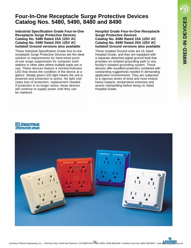
WIR
ED
-IN
DE
VIC
ESFour-In-One Receptacle Surge Protective Devices
Catalog Nos. 5480, 5490, 8480 and 8490
Industrial Specification Grade Four-In-OneReceptacle Surge Protective DevicesCatalog No. 5480 Rated 15A 125V AC Catalog No. 5490 Rated 20A 125V ACIsolated Ground versions also availableThese Industrial Specification Grade four-in-onereceptacle Surge Protective Devices are the idealsolution to requirements for hard-wired point-of-use surge suppression for computer work stations or other sites where multiple loads are inuse. These devices feature a monitor/indicator LED that shows the condition of the device at aglance: Steady green LED light means the unit ispowered and protection is active. No light indi-cates loss of protection, replacement needed. If protection is no longer active, these devices will continue to supply power until they can be replaced.
Hospital Grade Four-In-One ReceptacleSurge Protective DevicesCatalog No. 8480 Rated 15A 125V ACCatalog No. 8490 Rated 20A 125V ACIsolated Ground versions also availableThese Isolated Ground units are UL listedHospital Grade, and they are equipped with a separate detached pigtail ground lead thatprovides an isolated grounding path to any facility’s isolated grounding system. Thesedevices offer excellent protection combined withoutstanding ruggedness needed in demandingapplication environments. They are subjected to a rigorous series of tests and must endure heavy impacts, temperature extremes andsevere mishandling before being UL listed Hospital Grade.
35
Courtesy of Steven Engineering, Inc. ! 230 Ryan Way, South San Francisco, CA 94080-6370 ! Main Office: (650) 588-9200 ! Outside Local Area: (800) 258-9200 ! www.stevenengineering.com

HOSPITALGRADE
®
15A-125V
1.150(29.21mm)
4.50 (114.3mm)
4.50
(114
.3m
m)
LIGHT ONSURGE
PROTECTED
General DataSpecification Data Applicable To All
Rated line voltage 120V (VRMS)
Maximum continuous 135V operating voltage
Operating Frequency Range 50,60Hz
Max. single-pulse 13000A (L-N)transient current 6500A (L-G)(8x20µs, Amps peak) 6500A (N-G)
Rated single-pulse 320 Joulestransient energy(10x1000µs, impulse)
Noise rejection -35 dB@ 5kHz-5MHz
Clamping Performance
Physical Specifications
Agency Approvals
Dimensional Drawings
Operating Temperature Range: -10°C to 60°C
Storage Temperature Range: -20°C to 85°C
Wiring Means -Screw Terminals accept14AWG to 10AWG conductors (Hospital Grade and Isolated Ground units equipped with seperate pigtail lead for ground termination)
All devices UL Listed 1449 Standard.
All 15 Amp devices also CSA Certified
Specification Data Applicable To All
UL Standard 1449 L-N: 500V Peakpermanently-wired L-G: 500V Peaktest (8x20µs, 3000A) N-G: 500V Peak
Catalog Listing
Cat. No. Cat. No. Description15A - 125V 20A - 125V
5480-I 5490-I Ivory5480-W 5490-W White5480-GY 5490-GY Gray5480-R —— Red5480-BU 5490-BU Blue5480-IG 5490-IG Isolated Ground, Orange5480-IGI 5490-IGI Isolated Ground, Ivory5480-IGB 5490-IGB Isolated Ground, Blue8480-I 8490-I Hospital Grade/Ivory8480-W 8490-W Hospital Grade/White8480-R 8490-R Hospital Grade/Red8480-IGI 8490-IGI Hospital Grade/Isol. Ground, Ivory8480-IGW 8490-IGW Hospital Grade/Isol. Ground, White8480-IGB 8490-IGB Hospital Grade/Isol. Ground, Blue8480-IG 8490-IG Hospital Grade/Isol. Ground, Orange
G
W
GW
All SPD receptacles are backed by Leviton’s limited ten year warranty
36
WIR
ED
-IN
DE
VIC
ES
Courtesy of Steven Engineering, Inc. ! 230 Ryan Way, South San Francisco, CA 94080-6370 ! Main Office: (650) 588-9200 ! Outside Local Area: (800) 258-9200 ! www.stevenengineering.com
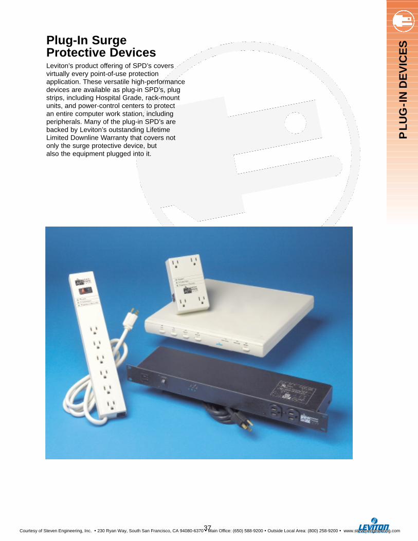
PL
UG
-IN
DE
VIC
ESPlug-In Surge
Protective DevicesLeviton’s product offering of SPD’s covers virtually every point-of-use protection application. These versatile high-performancedevices are available as plug-in SPD’s, plugstrips, including Hospital Grade, rack-mountunits, and power-control centers to protect an entire computer work station, includingperipherals. Many of the plug-in SPD’s arebacked by Leviton’s outstanding LifetimeLimited Downline Warranty that covers notonly the surge protective device, but also the equipment plugged into it.
37
Courtesy of Steven Engineering, Inc. ! 230 Ryan Way, South San Francisco, CA 94080-6370 ! Main Office: (650) 588-9200 ! Outside Local Area: (800) 258-9200 ! www.stevenengineering.com
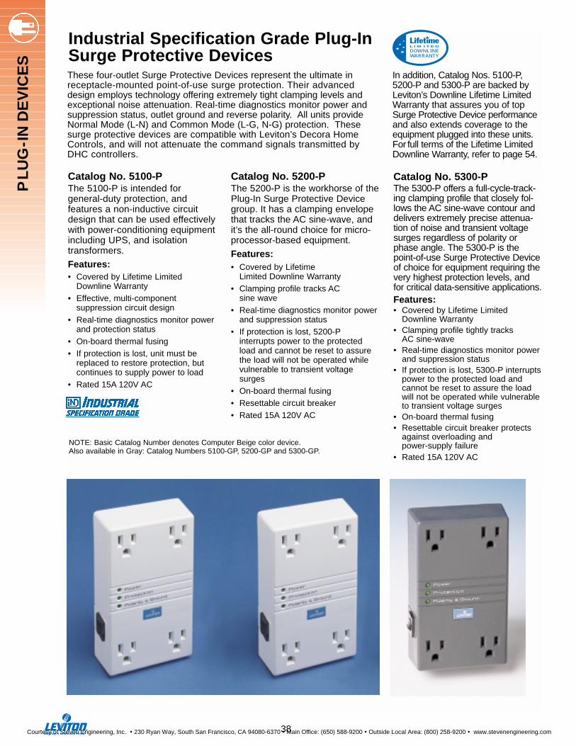
Catalog No. 5200-PThe 5200-P is the workhorse of thePlug-In Surge Protective Devicegroup. It has a clamping envelopethat tracks the AC sine-wave, andit’s the all-round choice for micro-processor-based equipment.
Features:• Covered by Lifetime
Limited Downline Warranty• Clamping profile tracks AC
sine wave• Real-time diagnostics monitor power
and suppression status• If protection is lost, 5200-P
interrupts power to the protected load and cannot be reset to assure the load will not be operated while vulnerable to transient voltage surges
• On-board thermal fusing• Resettable circuit breaker • Rated 15A 120V AC
Catalog No. 5100-PThe 5100-P is intended for general-duty protection, and features a non-inductive circuitdesign that can be used effectivelywith power-conditioning equipmentincluding UPS, and isolation transformers.
Features:• Covered by Lifetime Limited
Downline Warranty• Effective, multi-component
suppression circuit design• Real-time diagnostics monitor power
and protection status• On-board thermal fusing• If protection is lost, unit must be
replaced to restore protection, but continues to supply power to load
• Rated 15A 120V AC
Industrial Specification Grade Plug-In Surge Protective Devices
Catalog No. 5300-PThe 5300-P offers a full-cycle-track-ing clamping profile that closely fol-lows the AC sine-wave contour anddelivers extremely precise attenua-tion of noise and transient voltagesurges regardless of polarity orphase angle. The 5300-P is thepoint-of-use Surge Protective Deviceof choice for equipment requiring thevery highest protection levels, andfor critical data-sensitive applications.Features:• Covered by Lifetime Limited
Downline Warranty• Clamping profile tightly tracks
AC sine-wave• Real-time diagnostics monitor power
and suppression status• If protection is lost, 5300-P interrupts
power to the protected load and cannot be reset to assure the load will not be operated while vulnerable to transient voltage surges
• On-board thermal fusing• Resettable circuit breaker protects
against overloading and power-supply failure
• Rated 15A 120V AC
These four-outlet Surge Protective Devices represent the ultimate inreceptacle-mounted point-of-use surge protection. Their advanceddesign employs technology offering extremely tight clamping levels andexceptional noise attenuation. Real-time diagnostics monitor power andsuppression status, outlet ground and reverse polarity. All units provideNormal Mode (L-N) and Common Mode (L-G, N-G) protection. Thesesurge protective devices are compatible with Leviton’s Decora HomeControls, and will not attenuate the command signals transmitted byDHC controllers.
In addition, Catalog Nos. 5100-P,5200-P and 5300-P are backed byLeviton’s Downline Lifetime LimitedWarranty that assures you of topSurge Protective Device performanceand also extends coverage to theequipment plugged into these units.For full terms of the Lifetime LimitedDownline Warranty, refer to page 54.
DOWNLINEWARRANTY
L I M I T E D
NOTE: Basic Catalog Number denotes Computer Beige color device. Also available in Gray: Catalog Numbers 5100-GP, 5200-GP and 5300-GP.
38
PL
UG
-IN
DE
VIC
ES
Courtesy of Steven Engineering, Inc. ! 230 Ryan Way, South San Francisco, CA 94080-6370 ! Main Office: (650) 588-9200 ! Outside Local Area: (800) 258-9200 ! www.stevenengineering.com
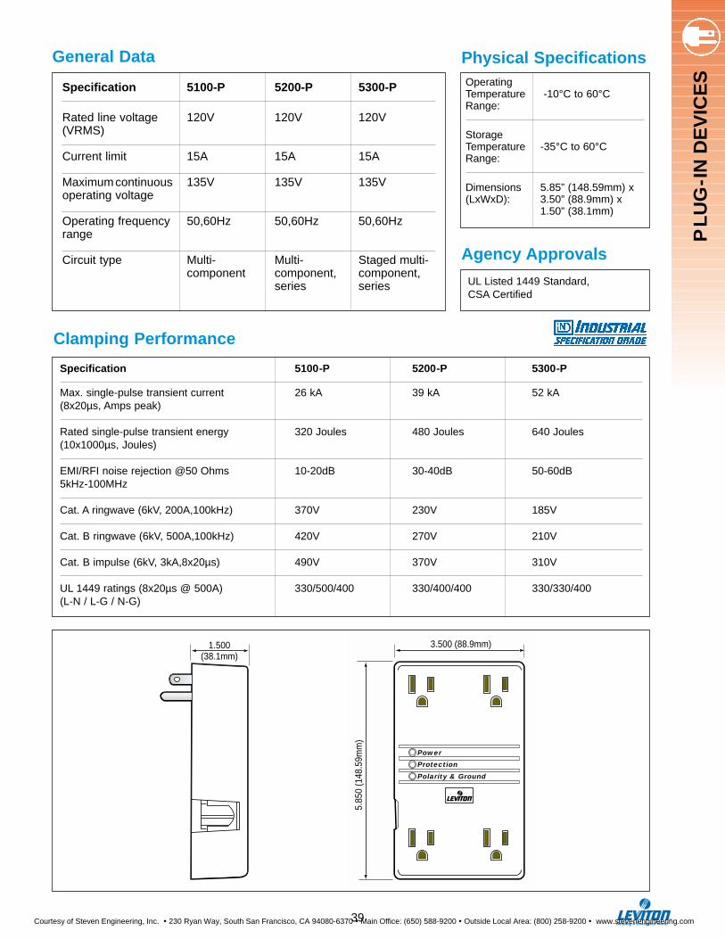
PL
UG
-IN
DE
VIC
ES
Physical Specifications
Agency Approvals
General Data
Clamping Performance
Specification 5100-P 5200-P 5300-P
Rated line voltage 120V 120V 120V(VRMS)
Current limit 15A 15A 15A
Maximumcontinuous 135V 135V 135Voperating voltage
Operating frequency 50,60Hz 50,60Hz 50,60Hzrange
Circuit type Multi- Multi- Staged multi-component component, component,
series series
Specification 5100-P 5200-P 5300-P
Max. single-pulse transient current 26 kA 39 kA 52 kA(8x20µs, Amps peak)
Rated single-pulse transient energy 320 Joules 480 Joules 640 Joules(10x1000µs, Joules)
EMI/RFI noise rejection @50 Ohms 10-20dB 30-40dB 50-60dB5kHz-100MHz
Cat. A ringwave (6kV, 200A,100kHz) 370V 230V 185V
Cat. B ringwave (6kV, 500A,100kHz) 420V 270V 210V
Cat. B impulse (6kV, 3kA,8x20µs) 490V 370V 310V
UL 1449 ratings (8x20µs @ 500A) 330/500/400 330/400/400 330/330/400(L-N / L-G / N-G)
Operating Temperature -10°C to 60°CRange:
Storage Temperature -35°C to 60°CRange:
Dimensions 5.85” (148.59mm) x (LxWxD): 3.50” (88.9mm) x
1.50” (38.1mm)
UL Listed 1449 Standard, CSA Certified
Power
Protection
Polarity & Ground
®
3.500 (88.9mm)
5.85
0 (1
48.5
9mm
)
1.500(38.1mm)
39
Courtesy of Steven Engineering, Inc. ! 230 Ryan Way, South San Francisco, CA 94080-6370 ! Main Office: (650) 588-9200 ! Outside Local Area: (800) 258-9200 ! www.stevenengineering.com
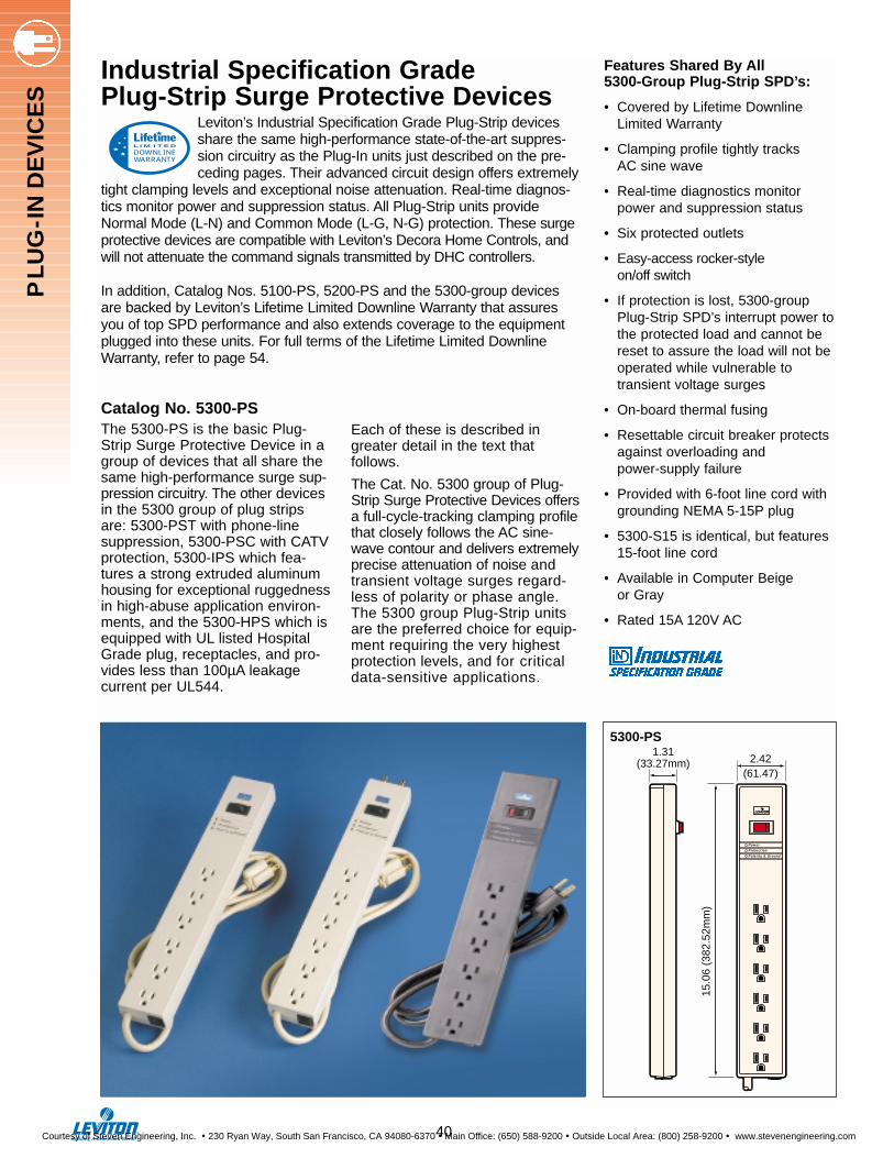
Industrial Specification Grade Plug-Strip Surge Protective Devices
Leviton’s Industrial Specification Grade Plug-Strip devicesshare the same high-performance state-of-the-art suppres-sion circuitry as the Plug-In units just described on the pre-ceding pages. Their advanced circuit design offers extremely
tight clamping levels and exceptional noise attenuation. Real-time diagnos-tics monitor power and suppression status. All Plug-Strip units provideNormal Mode (L-N) and Common Mode (L-G, N-G) protection. These surgeprotective devices are compatible with Leviton’s Decora Home Controls, andwill not attenuate the command signals transmitted by DHC controllers.
In addition, Catalog Nos. 5100-PS, 5200-PS and the 5300-group devicesare backed by Leviton’s Lifetime Limited Downline Warranty that assuresyou of top SPD performance and also extends coverage to the equipmentplugged into these units. For full terms of the Lifetime Limited DownlineWarranty, refer to page 54.
Catalog No. 5300-PSThe 5300-PS is the basic Plug-Strip Surge Protective Device in agroup of devices that all share thesame high-performance surge sup-pression circuitry. The other devicesin the 5300 group of plug stripsare: 5300-PST with phone-linesuppression, 5300-PSC with CATVprotection, 5300-IPS which fea-tures a strong extruded aluminumhousing for exceptional ruggednessin high-abuse application environ-ments, and the 5300-HPS which isequipped with UL listed HospitalGrade plug, receptacles, and pro-vides less than 100µA leakage current per UL544.
Features Shared By All 5300-Group Plug-Strip SPD’s:
• Covered by Lifetime Downline Limited Warranty
• Clamping profile tightly tracks AC sine wave
• Real-time diagnostics monitor power and suppression status
• Six protected outlets
• Easy-access rocker-style on/off switch
• If protection is lost, 5300-group Plug-Strip SPD’s interrupt power tothe protected load and cannot be reset to assure the load will not be operated while vulnerable to transient voltage surges
• On-board thermal fusing
• Resettable circuit breaker protects against overloading and power-supply failure
• Provided with 6-foot line cord with grounding NEMA 5-15P plug
• 5300-S15 is identical, but features 15-foot line cord
• Available in Computer Beige or Gray
• Rated 15A 120V AC
Each of these is described ingreater detail in the text that follows.
The Cat. No. 5300 group of Plug-Strip Surge Protective Devices offersa full-cycle-tracking clamping profilethat closely follows the AC sine-wave contour and delivers extremelyprecise attenuation of noise andtransient voltage surges regard-less of polarity or phase angle.The 5300 group Plug-Strip unitsare the preferred choice for equip-ment requiring the very highestprotection levels, and for criticaldata-sensitive applications.
DOWNLINEWARRANTY
L I M I T E D
2.42(61.47)
1.31(33.27mm)
15.0
6 (3
82.5
2mm
)
Power
Protection
Polarity & Ground
®
5300-PS
PL
UG
-IN
DE
VIC
ES
40
Courtesy of Steven Engineering, Inc. ! 230 Ryan Way, South San Francisco, CA 94080-6370 ! Main Office: (650) 588-9200 ! Outside Local Area: (800) 258-9200 ! www.stevenengineering.com
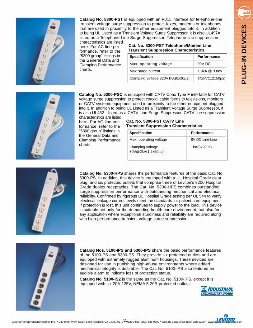
Catalog No. 5300-PSC is equipped with CATV Coax Type F interface for CATVvoltage surge suppression to protect coaxial cable feeds to televisions, monitorsor CATV systems equipment used in proximity to the other equipment pluggedinto it. In addition to being UL Listed as a Transient Voltage Surge Suppressor, it is also UL452 listed as a CATV Line Surge Suppressor. CATV line suppressioncharacteristics are listedhere. For AC-line per-formance, refer to the“5300 group” listings inthe General Data andClamping Performancecharts.
Catalog No. 5300-PST is equipped with an RJ11 interface for telephone-linetransient voltage surge suppression to protect faxes, modems or telephonesthat are used in proximity to the other equipment plugged into it. In addition to being UL Listed as a Transient Voltage Surge Suppressor, it is also UL497Alisted as a Telephone Line Surge Suppressor. Telephone line suppression characteristics are listedhere. For AC-line per-formance, refer to the“5300 group” listings inthe General Data andClamping Performancecharts.
Cat. No. 5300-PST Telephone/Modem Line Transient Suppression Characteristics
Cat. No. 5300-PST CATV Line Transient Suppression Characteristics
Specification Performance
Max. operating voltage 90V DC
Max.surge current 1.9kA @ 3.8kV
Clamping voltage 220V1kA(8x20µs) @2kV(1.2x50µs)
Specification Performance
Max. operating voltage 8V DC Line-Line
Clamping voltage 1kA(8x20µs)30V@2kV(1.2x50µs)
Catalog Nos. 5100-IPS and 5300-IPS share the basic performance featuresof the 5100-PS and 5300-PS. They provide six protected outlets and areequipped with extremely rugged aluminum housings. These devices aredesigned for use in punishing high-abuse environments where addedmechanical integrity is desirable. The Cat. No. 5100-IPS also features an audible alarm to indicate loss of protection status.
Catalog No. 5100-IS2 is the same as the Cat. No. 5100-IPS, except it isequipped with six 20A-125V, NEMA 5-20R protected outlets.
Catalog No. 5300-HPS shares the performance features of the basic Cat. No.5300-PS. In addition, this device is equipped with a UL Hospital Grade clearplug, and six protected outlets that comprise three of Leviton’s 8200 HospitalGrade duplex receptacles. The Cat. No. 5300-HPS combines outstandingsurge suppression performance with outstanding mechanical and electricalreliability. Confirmed by rigorous UL Hospital Grade testing per UL 544 to verifyelectrical leakage current levels meet the standards for patient care equipment.If protection is lost, this unit continues to supply power to the load. This deviceis suitable not only for the demanding health-care environment, but also forany application where exceptional sturdiness and reliability are required alongwith high-performance transient voltage surge suppression.
PL
UG
-IN
DE
VIC
ES
41
Courtesy of Steven Engineering, Inc. ! 230 Ryan Way, South San Francisco, CA 94080-6370 ! Main Office: (650) 588-9200 ! Outside Local Area: (800) 258-9200 ! www.stevenengineering.com
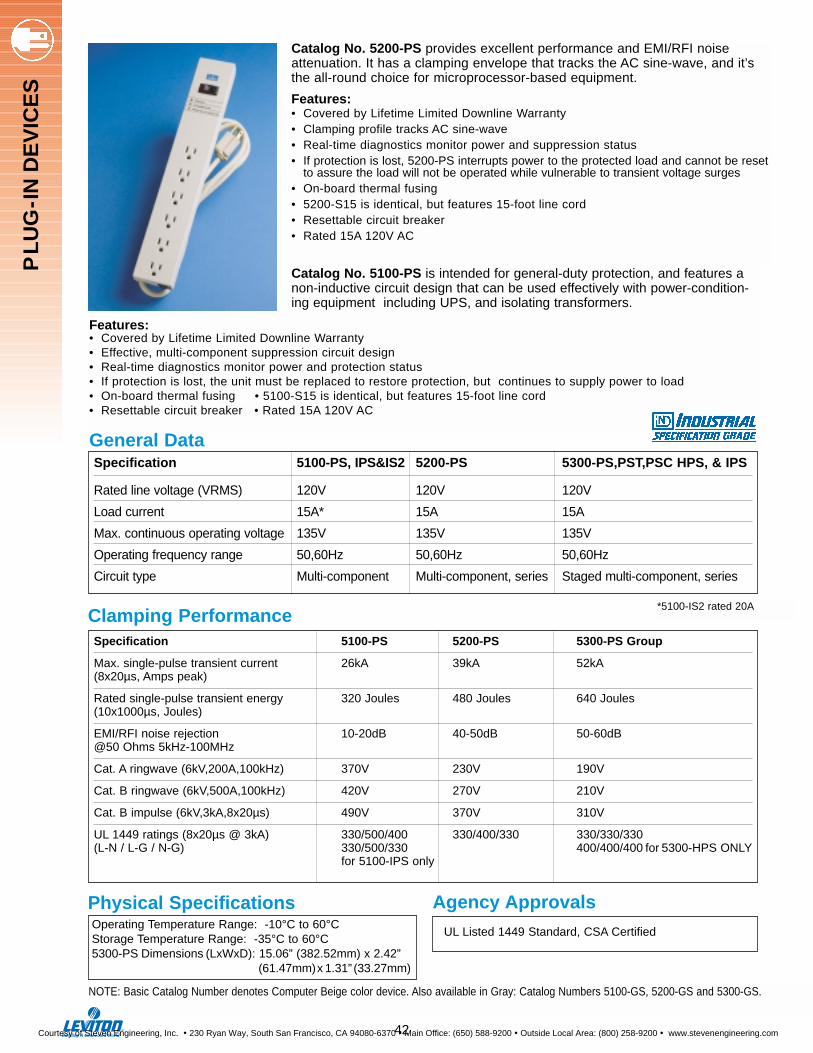
Catalog No. 5200-PS provides excellent performance and EMI/RFI noise attenuation. It has a clamping envelope that tracks the AC sine-wave, and it’sthe all-round choice for microprocessor-based equipment.
Features:• Covered by Lifetime Limited Downline Warranty• Clamping profile tracks AC sine-wave• Real-time diagnostics monitor power and suppression status• If protection is lost, 5200-PS interrupts power to the protected load and cannot be reset
to assure the load will not be operated while vulnerable to transient voltage surges• On-board thermal fusing• 5200-S15 is identical, but features 15-foot line cord• Resettable circuit breaker • Rated 15A 120V AC
Catalog No. 5100-PS is intended for general-duty protection, and features anon-inductive circuit design that can be used effectively with power-condition-ing equipment including UPS, and isolating transformers.
Operating Temperature Range: -10°C to 60°CStorage Temperature Range: -35°C to 60°C5300-PS Dimensions (LxWxD): 15.06” (382.52mm) x 2.42”
(61.47mm)x 1.31” (33.27mm)
UL Listed 1449 Standard, CSA Certified
Specification 5100-PS, IPS&IS2 5200-PS 5300-PS,PST,PSC HPS, & IPS
Rated line voltage (VRMS) 120V 120V 120V
Load current 15A* 15A 15A
Max. continuous operating voltage 135V 135V 135V
Operating frequency range 50,60Hz 50,60Hz 50,60Hz
Circuit type Multi-component Multi-component, series Staged multi-component, series
General Data
Clamping Performance
Physical Specifications Agency Approvals
Specification 5100-PS 5200-PS 5300-PS Group
Max. single-pulse transient current 26kA 39kA 52kA(8x20µs, Amps peak)
Rated single-pulse transient energy 320 Joules 480 Joules 640 Joules(10x1000µs, Joules)
EMI/RFI noise rejection 10-20dB 40-50dB 50-60dB@50 Ohms 5kHz-100MHz
Cat. A ringwave (6kV,200A,100kHz) 370V 230V 190V
Cat. B ringwave (6kV,500A,100kHz) 420V 270V 210V
Cat. B impulse (6kV,3kA,8x20µs) 490V 370V 310V
UL 1449 ratings (8x20µs @ 3kA) 330/500/400 330/400/330 330/330/330(L-N / L-G / N-G) 330/500/330 400/400/400 for 5300-HPS ONLY
for 5100-IPS only
Features:• Covered by Lifetime Limited Downline Warranty• Effective, multi-component suppression circuit design• Real-time diagnostics monitor power and protection status• If protection is lost, the unit must be replaced to restore protection, but continues to supply power to load• On-board thermal fusing • 5100-S15 is identical, but features 15-foot line cord• Resettable circuit breaker • Rated 15A 120V AC
*5100-IS2 rated 20A
NOTE: Basic Catalog Number denotes Computer Beige color device. Also available in Gray: Catalog Numbers 5100-GS, 5200-GS and 5300-GS.
42
PL
UG
-IN
DE
VIC
ES
Courtesy of Steven Engineering, Inc. ! 230 Ryan Way, South San Francisco, CA 94080-6370 ! Main Office: (650) 588-9200 ! Outside Local Area: (800) 258-9200 ! www.stevenengineering.com
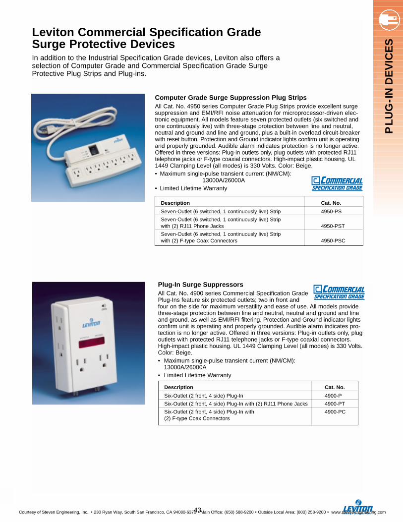
PL
UG
-IN
DE
VIC
ES
Leviton Commercial Specification Grade Surge Protective Devices In addition to the Industrial Specification Grade devices, Leviton also offers aselection of Computer Grade and Commercial Specification Grade SurgeProtective Plug Strips and Plug-ins.
Computer Grade Surge Suppression Plug StripsAll Cat. No. 4950 series Computer Grade Plug Strips provide excellent surgesuppression and EMI/RFI noise attenuation for microprocessor-driven elec-tronic equipment. All models feature seven protected outlets (six switched andone continuously live) with three-stage protection between line and neutral,neutral and ground and line and ground, plus a built-in overload circuit-breakerwith reset button. Protection and Ground indicator lights confirm unit is operatingand properly grounded. Audible alarm indicates protection is no longer active.Offered in three versions: Plug-in outlets only, plug outlets with protected RJ11telephone jacks or F-type coaxial connectors. High-impact plastic housing. UL1449 Clamping Level (all modes) is 330 Volts. Color: Beige.• Maximum single-pulse transient current (NM/CM):
13000A/26000A• Limited Lifetime Warranty
Description Cat. No.
Seven-Outlet (6 switched, 1 continuously live) Strip 4950-PS
Seven-Outlet (6 switched, 1 continuously live) Strip with (2) RJ11 Phone Jacks 4950-PST
Seven-Outlet (6 switched, 1 continuously live) Stripwith (2) F-type Coax Connectors 4950-PSC
Plug-In Surge SuppressorsAll Cat. No. 4900 series Commercial Specification GradePlug-Ins feature six protected outlets; two in front andfour on the side for maximum versatility and ease of use. All models providethree-stage protection between line and neutral, neutral and ground and lineand ground, as well as EMI/RFI filtering. Protection and Ground indicator lightsconfirm unit is operating and properly grounded. Audible alarm indicates pro-tection is no longer active. Offered in three versions: Plug-in outlets only, plugoutlets with protected RJ11 telephone jacks or F-type coaxial connectors.High-impact plastic housing. UL 1449 Clamping Level (all modes) is 330 Volts.Color: Beige.• Maximum single-pulse transient current (NM/CM):
13000A/26000A• Limited Lifetime Warranty
Description Cat. No.
Six-Outlet (2 front, 4 side) Plug-In 4900-P
Six-Outlet (2 front, 4 side) Plug-In with (2) RJ11 Phone Jacks 4900-PT
Six-Outlet (2 front, 4 side) Plug-In with 4900-PC(2) F-type Coax Connectors
43
Courtesy of Steven Engineering, Inc. ! 230 Ryan Way, South San Francisco, CA 94080-6370 ! Main Office: (650) 588-9200 ! Outside Local Area: (800) 258-9200 ! www.stevenengineering.com
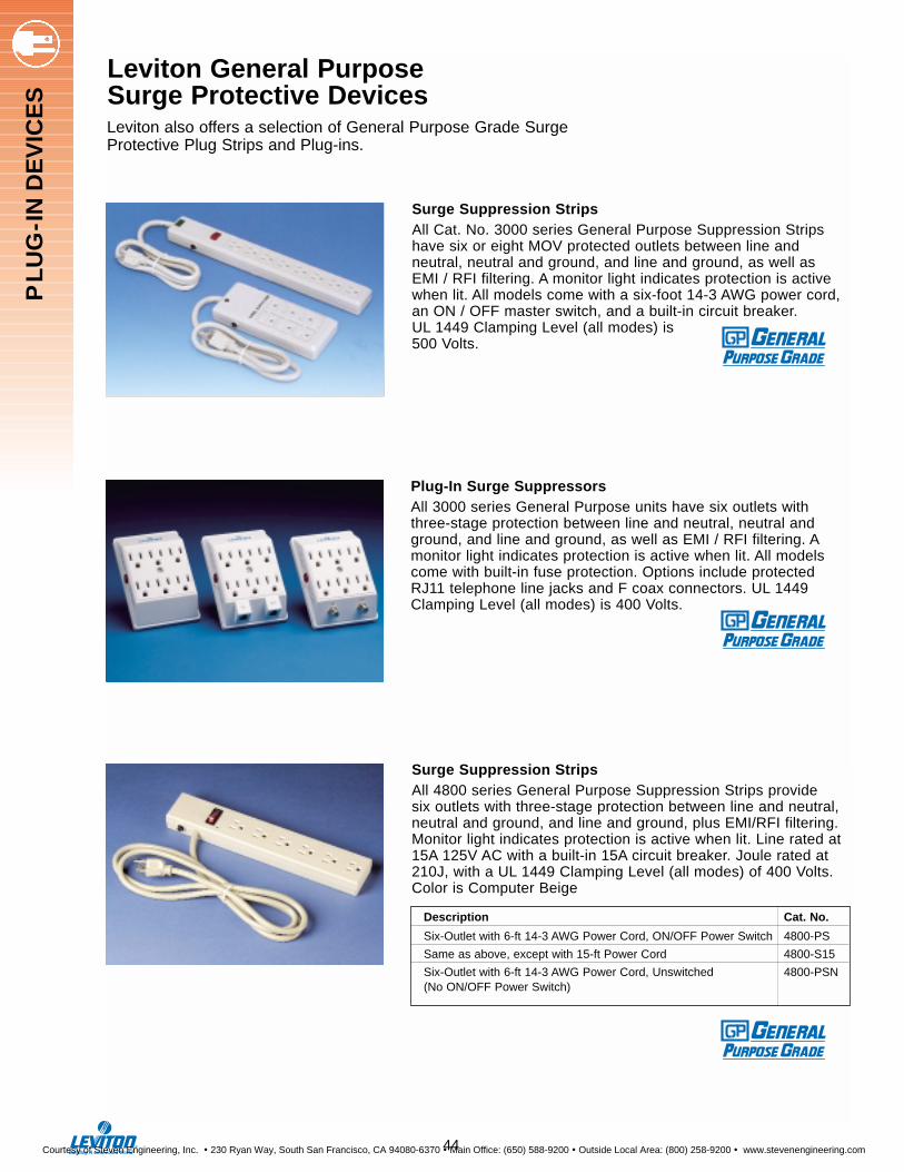
Surge Suppression StripsAll Cat. No. 3000 series General Purpose Suppression Stripshave six or eight MOV protected outlets between line andneutral, neutral and ground, and line and ground, as well asEMI / RFI filtering. A monitor light indicates protection is activewhen lit. All models come with a six-foot 14-3 AWG power cord,an ON / OFF master switch, and a built-in circuit breaker. UL 1449 Clamping Level (all modes) is 500 Volts.
Plug-In Surge SuppressorsAll 3000 series General Purpose units have six outlets withthree-stage protection between line and neutral, neutral andground, and line and ground, as well as EMI / RFI filtering. Amonitor light indicates protection is active when lit. All modelscome with built-in fuse protection. Options include protectedRJ11 telephone line jacks and F coax connectors. UL 1449Clamping Level (all modes) is 400 Volts.
Leviton General PurposeSurge Protective Devices Leviton also offers a selection of General Purpose Grade Surge Protective Plug Strips and Plug-ins.
PL
UG
-IN
DE
VIC
ES
44
Surge Suppression StripsAll 4800 series General Purpose Suppression Strips provide six outlets with three-stage protection between line and neutral, neutral and ground, and line and ground, plus EMI/RFI filtering.Monitor light indicates protection is active when lit. Line rated at15A 125V AC with a built-in 15A circuit breaker. Joule rated at210J, with a UL 1449 Clamping Level (all modes) of 400 Volts.Color is Computer Beige
Description Cat. No.
Six-Outlet with 6-ft 14-3 AWG Power Cord, ON/OFF Power Switch 4800-PS
Same as above, except with 15-ft Power Cord 4800-S15
Six-Outlet with 6-ft 14-3 AWG Power Cord, Unswitched 4800-PSN(No ON/OFF Power Switch)
Courtesy of Steven Engineering, Inc. ! 230 Ryan Way, South San Francisco, CA 94080-6370 ! Main Office: (650) 588-9200 ! Outside Local Area: (800) 258-9200 ! www.stevenengineering.com
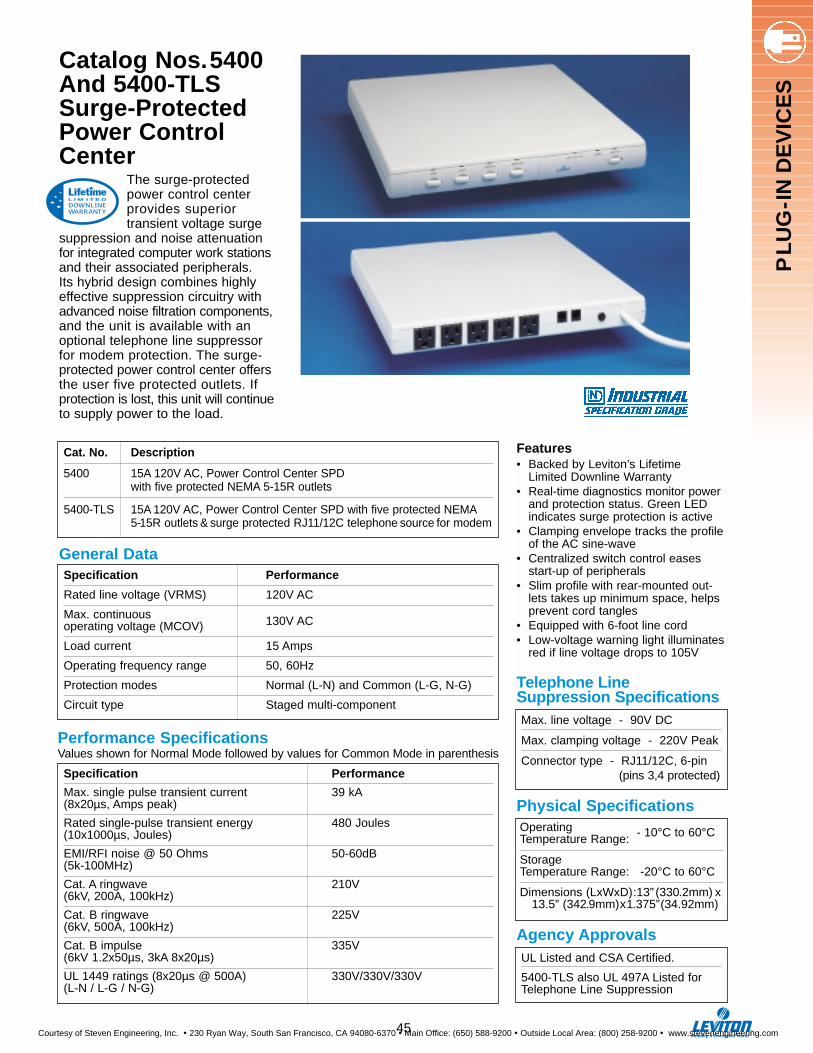
Performance SpecificationsValues shown for Normal Mode followed by values for Common Mode in parenthesis
The surge-protectedpower control center provides superiortransient voltage surge
suppression and noise attenuationfor integrated computer work stationsand their associated peripherals. Its hybrid design combines highlyeffective suppression circuitry withadvanced noise filtration components,and the unit is available with anoptional telephone line suppressor for modem protection. The surge-protected power control center offersthe user five protected outlets. If protection is lost, this unit will continueto supply power to the load.
Catalog Nos.5400And 5400-TLSSurge-ProtectedPower ControlCenter
Features• Backed by Leviton’s Lifetime
Limited Downline Warranty• Real-time diagnostics monitor power
and protection status. Green LED indicates surge protection is active
• Clamping envelope tracks the profileof the AC sine-wave
• Centralized switch control eases start-up of peripherals
• Slim profile with rear-mounted out-lets takes up minimum space, helps prevent cord tangles
• Equipped with 6-foot line cord• Low-voltage warning light illuminates
red if line voltage drops to 105V
Cat. No. Description
5400 15A 120V AC, Power Control Center SPDwith five protected NEMA 5-15R outlets
5400-TLS 15A 120V AC, Power Control Center SPD with five protected NEMA5-15R outlets & surge protected RJ11/12C telephone source for modem
Specification Performance
Rated line voltage (VRMS) 120V AC
Max. continuous 130V ACoperating voltage (MCOV)
Load current 15 Amps
Operating frequency range 50, 60Hz
Protection modes Normal (L-N) and Common (L-G, N-G)
Circuit type Staged multi-component
Specification Performance
Max. single pulse transient current 39 kA(8x20µs, Amps peak)
Rated single-pulse transient energy 480 Joules(10x1000µs, Joules)
EMI/RFI noise @ 50 Ohms 50-60dB(5k-100MHz)
Cat. A ringwave 210V(6kV, 200A, 100kHz)
Cat. B ringwave 225V(6kV, 500A, 100kHz)
Cat. B impulse 335V(6kV 1.2x50µs, 3kA 8x20µs)
UL 1449 ratings (8x20µs @ 500A) 330V/330V/330V(L-N / L-G / N-G)
DOWNLINEWARRANTY
L I M I T E D
Max. line voltage - 90V DC
Max. clamping voltage - 220V Peak
Connector type - RJ11/12C, 6-pin (pins 3,4 protected)
Telephone Line Suppression Specifications
Operating Temperature Range: - 10°C to 60°C
Storage Temperature Range: -20°C to 60°C
Dimensions (LxWxD):13” (330.2mm) x13.5” (342.9mm)x1.375”(34.92mm)
Physical Specifications
Agency ApprovalsUL Listed and CSA Certified.
5400-TLS also UL 497A Listed forTelephone Line Suppression
General Data
PL
UG
-IN
DE
VIC
ES
45
Courtesy of Steven Engineering, Inc. ! 230 Ryan Way, South San Francisco, CA 94080-6370 ! Main Office: (650) 588-9200 ! Outside Local Area: (800) 258-9200 ! www.stevenengineering.com

Features• Covered by Lifetime Limited
Downline Warranty• Mounts on 19-inch equipment
racks to provide point -of-use surge suppression for electronic equipment
• Clamping profile tightly tracks AC sine-wave
• Six protected duplex recepta-cles—(5) in back, (1) in front
• Available with 15A-120V or 20A-120V receptacles
• Easy access rocker-styleON/OFF switch
• Available without ON/OFF switch to prevent accidental switching of electronic equipment (Cat. Nos. 5500-15N and 5500-20N)
• Resettable circuit breaker protects against overloading and power-supply failure
• Provided with 12-foot line cord with grounding NEMA 5-15P, 5-20P or L5-20P (Cat. No. 5500-20L) plug.
• UL Recognized Component
Industrial Specification Grade Catalog No. 5500 19-inch Rack-Mount Surge Protective Devices
These devices are designed for mounting on 19-inchracks where transient voltage surge suppression isdesired for rack-mounted electronic equipment. The Cat.No. 5500 offers a total of six surge suppression duplex
receptacles, (five) on back and (one) in front, to provide forthe easy, convenient plug-in of all mounted equipment. The advancedcircuit design of the No. 5500 offers extremely tight clamping levelsand exceptional noise attenuation. Each receptacle provides NormalMode (L-N) and Common Mode (L-G, N-G) protection.
In addition, Catalog No. 5500 rack-mount devices are backed byLeviton’s Lifetime Limited Downline Warranty that assures you of top SPD performance and also extends coverage to the equipmentplugged into these units. For full terms of the Lifetime LimitedDownline Warranty, refer to page 54.
DOWNLINEWARRANTY
L I M I T E D
46
PL
UG
-IN
DE
VIC
ES
Courtesy of Steven Engineering, Inc. ! 230 Ryan Way, South San Francisco, CA 94080-6370 ! Main Office: (650) 588-9200 ! Outside Local Area: (800) 258-9200 ! www.stevenengineering.com

PL
UG
-IN
DE
VIC
ES
Operating Temperature Range: -10°C to 60°CStorage Temperature Range: -35°C to 60°C5500-190, 192 Dimensions: L-19”(482.6mm)x
W- 4.55”(115.57mm)xD-1.71”(43.43mm)
UL Recognized Component, CSA Certified
Specification 5500-190, 5500-15N 5500-192, 5500-20N, 5500-20L
Rated line voltage (VRMS) 120V 120V
Load current 15A 20A
Max. continuous operating voltage 135V 135V
Operating frequency range 50,60Hz 50,60Hz
Circuit type Staged multi-component, series Staged multi-component, series
General Data
Clamping Performance
Physical Specifications Agency Approvals
Values shown for Normal Mode followed by values for Common Mode in parenthesis
Specification 5500-190, 5500-192, 5500-15N, 5500-20N, 5500-2L
Max. single-pulse transient current52KA(8x20µs, Amps peak)
Rated single-pulse transient energy 640 Joules(10x1000µs, Joules)
EMI/RFI noise rejection 50-60dB@50 Ohms 5kHz-100MHz (30-40dB)
Cat. A ringwave (6kV,200A,100kHz) 190V (350V)
Cat. B ringwave (6kV,500A,100kHz) 210V (370V)
Cat. B impulse (6kV,3kA,8x20µs) 310V (390V)
UL 1449 ratings (8x20µs @ 3kA) 330/330/330(L-N / L-G / N-G)
Dimensional Drawing
47
1.71
0 (4
3.43
mm
)
19.00 (482.6 mm)
4.55
(115
.57m
m)
Courtesy of Steven Engineering, Inc. ! 230 Ryan Way, South San Francisco, CA 94080-6370 ! Main Office: (650) 588-9200 ! Outside Local Area: (800) 258-9200 ! www.stevenengineering.com
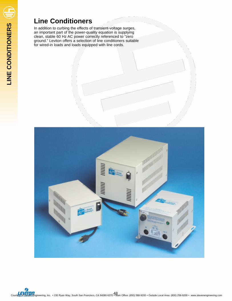
LIN
EC
ON
DIT
ION
ER
S
Line ConditionersIn addition to curbing the effects of transient-voltage surges,an important part of the power-quality equation is supplyingclean, stable 60 Hz AC power correctly referenced to “zeroground.” Leviton offers a selection of line conditioners suitablefor wired-in loads and loads equipped with line cords.
48
Courtesy of Steven Engineering, Inc. ! 230 Ryan Way, South San Francisco, CA 94080-6370 ! Main Office: (650) 588-9200 ! Outside Local Area: (800) 258-9200 ! www.stevenengineering.com
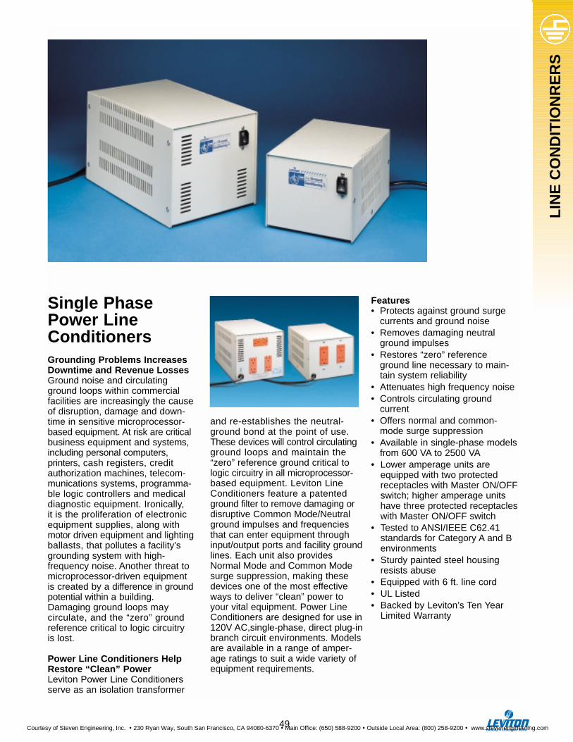
LIN
EC
ON
DIT
ION
RE
RS
Single PhasePower LineConditionersGrounding Problems IncreasesDowntime and Revenue LossesGround noise and circulatingground loops within commercialfacilities are increasingly the causeof disruption, damage and down-time in sensitive microprocessor-based equipment. At risk are criticalbusiness equipment and systems,including personal computers, printers, cash registers, creditauthorization machines, telecom-munications systems, programma-ble logic controllers and medicaldiagnostic equipment. Ironically, it is the proliferation of electronicequipment supplies, along withmotor driven equipment and lightingballasts, that pollutes a facility’sgrounding system with high-frequency noise. Another threat tomicroprocessor-driven equipmentis created by a difference in groundpotential within a building.Damaging ground loops may circulate, and the “zero” groundreference critical to logic circuitry is lost.
Power Line Conditioners HelpRestore “Clean” PowerLeviton Power Line Conditionersserve as an isolation transformer
and re-establishes the neutral-ground bond at the point of use.These devices will control circulatingground loops and maintain the“zero” reference ground critical tologic circuitry in all microprocessor-based equipment. Leviton LineConditioners feature a patentedground filter to remove damaging ordisruptive Common Mode/Neutralground impulses and frequenciesthat can enter equipment throughinput/output ports and facility groundlines. Each unit also providesNormal Mode and Common Modesurge suppression, making thesedevices one of the most effectiveways to deliver “clean” power toyour vital equipment. Power LineConditioners are designed for use in120V AC,single-phase, direct plug-inbranch circuit environments. Modelsare available in a range of amper-age ratings to suit a wide variety ofequipment requirements.
Features• Protects against ground surge
currents and ground noise• Removes damaging neutral
ground impulses• Restores “zero” reference
ground line necessary to main- tain system reliability
• Attenuates high frequency noise• Controls circulating ground
current• Offers normal and common-
mode surge suppression• Available in single-phase models
from 600 VA to 2500 VA• Lower amperage units are
equipped with two protected receptacles with Master ON/OFFswitch; higher amperage units have three protected receptacleswith Master ON/OFF switch
• Tested to ANSI/IEEE C62.41 standards for Category A and B environments
• Sturdy painted steel housing resists abuse
• Equipped with 6 ft. line cord• UL Listed• Backed by Leviton’s Ten Year
Limited Warranty
49
Courtesy of Steven Engineering, Inc. ! 230 Ryan Way, South San Francisco, CA 94080-6370 ! Main Office: (650) 588-9200 ! Outside Local Area: (800) 258-9200 ! www.stevenengineering.com
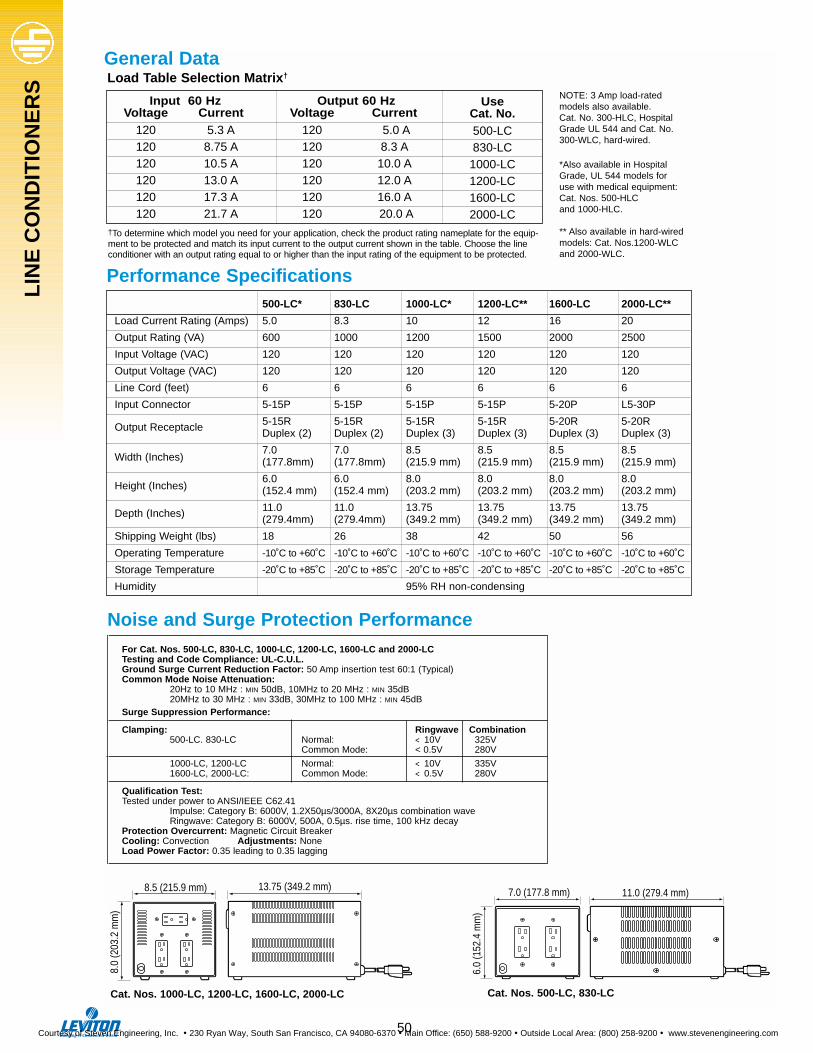
500-LC* 830-LC 1000-LC* 1200-LC** 1600-LC 2000-LC**
Load Current Rating (Amps) 5.0 8.3 10 12 16 20
Output Rating (VA) 600 1000 1200 1500 2000 2500
Input Voltage (VAC) 120 120 120 120 120 120
Output Voltage (VAC) 120 120 120 120 120 120
Line Cord (feet) 6 6 6 6 6 6
Input Connector 5-15P 5-15P 5-15P 5-15P 5-20P L5-30P
Output Receptacle 5-15R 5-15R 5-15R 5-15R 5-20R 5-20RDuplex (2) Duplex (2) Duplex (3) Duplex (3) Duplex (3) Duplex (3)
Width (Inches)7.0 7.0 8.5 8.5 8.5 8.5(177.8mm) (177.8mm) (215.9 mm) (215.9 mm) (215.9 mm) (215.9 mm)
Height (Inches)6.0 6.0 8.0 8.0 8.0 8.0(152.4 mm) (152.4 mm) (203.2 mm) (203.2 mm) (203.2 mm) (203.2 mm)
Depth (Inches) 11.0 11.0 13.75 13.75 13.75 13.75(279.4mm) (279.4mm) (349.2 mm) (349.2 mm) (349.2 mm) (349.2 mm)
Shipping Weight (lbs) 18 26 38 42 50 56
Operating Temperature -10˚C to +60˚C -10˚C to +60˚C -10˚C to +60˚C -10˚C to +60˚C -10˚C to +60˚C -10˚C to +60˚C
Storage Temperature -20˚C to +85˚C -20˚C to +85˚C -20˚C to +85˚C -20˚C to +85˚C -20˚C to +85˚C -20˚C to +85˚C
Humidity 95% RH non-condensing
Input 60 Hz Output 60 HzVoltage Current Voltage Current
120 5.3 A 120 5.0 A120 8.75 A 120 8.3 A120 10.5 A 120 10.0 A120 13.0 A 120 12.0 A120 17.3 A 120 16.0 A120 21.7 A 120 20.0 A
Performance Specifications
Load Table Selection Matrix†
8.5 (215.9 mm) 13.75 (349.2 mm)
8.0
(203
.2 m
m)
7.0 (177.8 mm) 11.0 (279.4 mm)
6.0
(152
.4 m
m)
Cat. Nos. 1000-LC, 1200-LC, 1600-LC, 2000-LC Cat. Nos. 500-LC, 830-LC
UseCat. No.500-LC830-LC
1000-LC1200-LC1600-LC2000-LC
†To determine which model you need for your application, check the product rating nameplate for the equip-ment to be protected and match its input current to the output current shown in the table. Choose the lineconditioner with an output rating equal to or higher than the input rating of the equipment to be protected.
General Data
Noise and Surge Protection Performance
NOTE: 3 Amp load-ratedmodels also available.Cat. No. 300-HLC, HospitalGrade UL 544 and Cat. No.300-WLC, hard-wired.
*Also available in HospitalGrade, UL 544 models foruse with medical equipment: Cat. Nos. 500-HLCand 1000-HLC.
** Also available in hard-wiredmodels: Cat. Nos.1200-WLCand 2000-WLC.
For Cat. Nos. 500-LC, 830-LC, 1000-LC, 1200-LC, 1600-LC and 2000-LC Testing and Code Compliance: UL-C.U.L.Ground Surge Current Reduction Factor: 50 Amp insertion test 60:1 (Typical)Common Mode Noise Attenuation:
20Hz to 10 MHz : MIN 50dB, 10MHz to 20 MHz : MIN 35dB20MHz to 30 MHz : MIN 33dB, 30MHz to 100 MHz : MIN 45dB
Surge Suppression Performance:
Clamping: Ringwave Combination500-LC. 830-LC Normal: < 10V 325V
Common Mode: < 0.5V 280V
1000-LC, 1200-LC Normal: < 10V 335V 1600-LC, 2000-LC: Common Mode: < 0.5V 280V
Qualification Test:Tested under power to ANSI/IEEE C62.41
Impulse: Category B: 6000V, 1.2X50µs/3000A, 8X20µs combination waveRingwave: Category B: 6000V, 500A, 0.5µs. rise time, 100 kHz decay
Protection Overcurrent: Magnetic Circuit BreakerCooling: Convection Adjustments: None Load Power Factor: 0.35 leading to 0.35 lagging
50
LIN
EC
ON
DIT
ION
ER
S
Courtesy of Steven Engineering, Inc. ! 230 Ryan Way, South San Francisco, CA 94080-6370 ! Main Office: (650) 588-9200 ! Outside Local Area: (800) 258-9200 ! www.stevenengineering.com
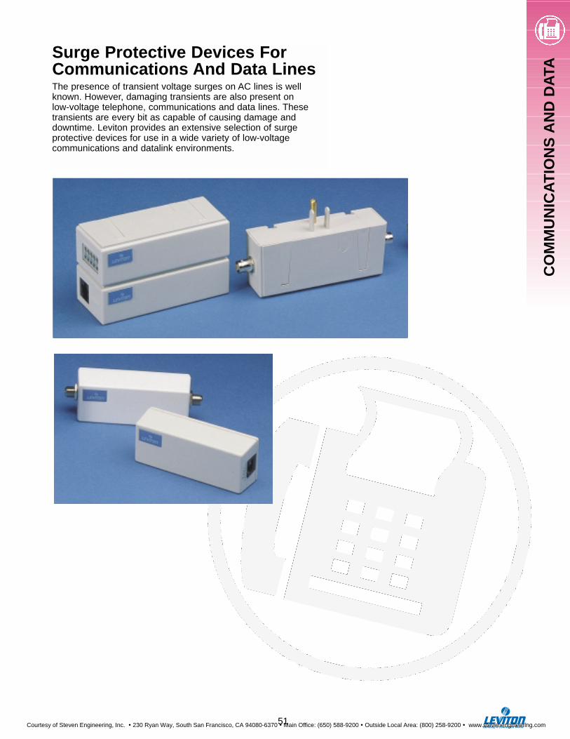
CO
MM
UN
ICA
TIO
NS
AN
DD
ATA
Surge Protective Devices ForCommunications And Data LinesThe presence of transient voltage surges on AC lines is wellknown. However, damaging transients are also present on low-voltage telephone, communications and data lines. Thesetransients are every bit as capable of causing damage and downtime. Leviton provides an extensive selection of surgeprotective devices for use in a wide variety of low-voltagecommunications and datalink environments.
51
Courtesy of Steven Engineering, Inc. ! 230 Ryan Way, South San Francisco, CA 94080-6370 ! Main Office: (650) 588-9200 ! Outside Local Area: (800) 258-9200 ! www.stevenengineering.com
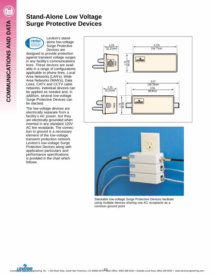
Leviton’s stand-alone low-voltageSurge ProtectiveDevices are
designed to provide protectionagainst transient voltage surgesin any facility’s communicationslines. These devices are avail-able in a range of configurationsapplicable to phone lines, LocalArea Networks (LAN’s), WideArea Networks (WAN’s), DataLines, CATV and CCTV cablenetworks. Individual devices canbe applied as needed and, inaddition, several low-voltageSurge Protective Devices can be stacked.
The low-voltage devices areelectrically separate from a facility’s AC power, but they are electrically grounded wheninserted in any standard 120VAC line receptacle. The connec-tion to ground is a necessaryelement of the low-voltage transient protection network.Leviton’s low-voltage SurgeProtective Devices along withapplication particulars and performance specifications is provided in the chart whichfollows.
®
Lin
e
1.2331.21mm
3.5088.9mm
5.07128.78mm
1.75
44.4
5
®
Lin
e
1.2331.21mm
4.125104.77mm
1.75
44.4
5
Stackable low-voltage Surge Protective Devices facilitateusing multiple devices sharing one AC receptacle as acommon ground point
DOWNLINEWARRANTY
L I M I T E D
Stand-Alone Low VoltageSurge Protective Devices
52
CO
MM
UN
ICA
TIO
NS
AN
D D
ATA
Courtesy of Steven Engineering, Inc. ! 230 Ryan Way, South San Francisco, CA 94080-6370 ! Main Office: (650) 588-9200 ! Outside Local Area: (800) 258-9200 ! www.stevenengineering.com
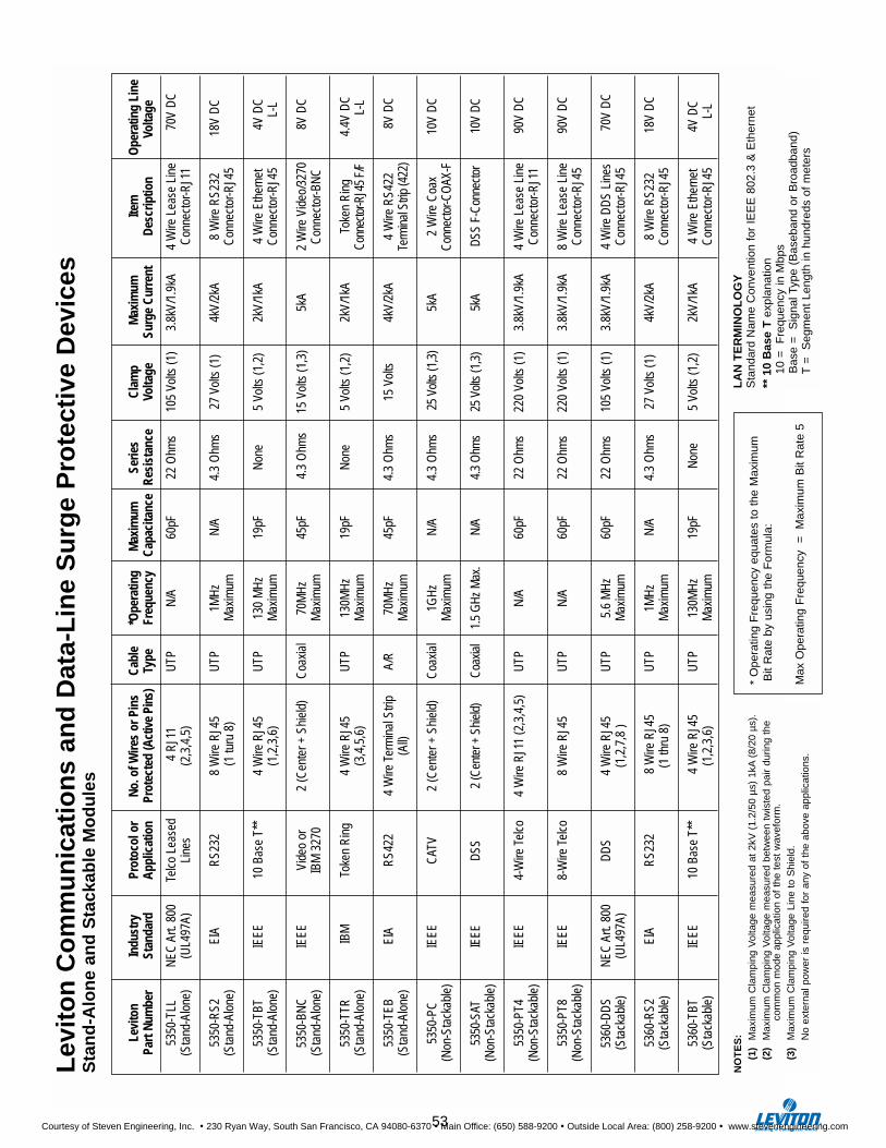
Levi
ton
Indu
stry
Prot
ocol
or
No. o
f Wire
s or
Pin
sCa
ble
*Ope
ratin
g M
axim
umSe
ries
Clam
pM
axim
umIte
m
Ope
ratin
g Li
nePa
rt Nu
mbe
rSt
anda
rdAp
plic
atio
nPr
otec
ted
(Act
ive
Pins
)Ty
peFr
eque
ncy
Capa
cita
nce
Resi
stan
ceVo
ltage
Surg
e Cu
rren
tDe
scrip
tion
Volta
ge
5350
-TLL
NEC
Art.
800
Telc
o Le
ased
4 R
J11
UTP
N/A
60pF
22 O
hms
105
Volts
(1)
3.8k
V/1.
9kA
4 W
ire L
ease
Lin
e70
V D
C(S
tand
-Alo
ne)
(UL4
97A)
Line
s(2
,3,4
,5)
Con
nect
or-R
J11
5350
-RS2
EIA
RS2
328
Wire
RJ4
5U
TP1M
Hz
N/A
4.3
Ohm
s27
Vol
ts (1
)4k
V/2k
A8
Wire
RS2
3218
V D
C(S
tand
-Alo
ne)
(1 tu
ru 8
)
Max
imum
Con
nect
or-R
J45
5350
-TBT
IEEE
10 B
ase
T**
4 W
ire R
J45
UTP
130
MH
z19
pFN
one
5 Vo
lts (1
,2)
2kV/
1kA
4 W
ire E
ther
net
4V D
C(S
tand
-Alo
ne)
(1,2
,3,6
)M
axim
umC
onne
ctor
-RJ4
5L-
L
5350
-BN
CIE
EEVi
deo
or2
(Cen
ter +
Shi
eld)
Coa
xial
70M
Hz
45pF
4.3
Ohm
s15
Vol
ts (1
,3)
5kA
2 W
ire V
ideo
/327
08V
DC
(Sta
nd-A
lone
)IB
M 3
270
Max
imum
Con
nect
or-B
NC
5350
-TTR
IBM
Toke
n R
ing
4 W
ire R
J45
UTP
130M
Hz
19pF
Non
e5
Volts
(1,2
)2k
V/1k
ATo
ken
Rin
g4.
4V D
C(S
tand
-Alo
ne)
(3,4
,5,6
)M
axim
umCo
nnec
tor-R
J45
F/F
L-L
5350
-TEB
EIA
RS4
224
Wire
Ter
min
al S
trip
A/R
70M
Hz
45pF
4.3
Ohm
s15
Vol
ts4k
V/2k
A4
Wire
RS4
228V
DC
(Sta
nd-A
lone
)(A
ll)M
axim
umTe
rmin
al S
trip
(422
)
5350
-PC
IEEE
CAT
V2
(Cen
ter +
Shi
eld)
Coa
xial
1GH
zN
/A4.
3 O
hms
25 V
olts
(1,3
)5k
A2
Wire
Coa
x10
V D
C(N
on-S
tack
able
)M
axim
umCo
nnec
tor-C
OAX
-F
5350
-SAT
IEEE
DSS
2 (C
ente
r + S
hiel
d)Co
axia
l1.
5 G
Hz M
ax.
N/A
4.3
Ohm
s25
Vol
ts (1
,3)
5kA
DSS
F-Co
nnec
tor
10V
DC(N
on-S
tack
able
)
5350
-PT4
IEEE
4-W
ire T
elco
4 W
ire R
J11
(2,3
,4,5
)U
TPN
/A60
pF22
Ohm
s22
0 Vo
lts (1
)3.
8kV/
1.9k
A4
Wire
Lea
se L
ine
90V
DC
(Non
-Sta
ckab
le)
Con
nect
or-R
J11
5350
-PT8
IEEE
8-W
ire T
elco
8 W
ire R
J45
UTP
N/A
60pF
22 O
hms
220
Volts
(1)
3.8k
V/1.
9kA
8 W
ire L
ease
Lin
e90
V D
C(N
on-S
tack
able
)C
onne
ctor
-RJ4
5
5360
-DD
SN
EC A
rt. 8
00D
DS
4 W
ire R
J45
UTP
5.6
MH
z60
pF22
Ohm
s10
5 Vo
lts (1
)3.
8kV/
1.9k
A4
Wire
DD
S Li
nes
70V
DC
(Sta
ckab
le)
(UL4
97A)
(1,2
,7,8
)
Max
imum
Con
nect
or-R
J45
5360
-RS2
EIA
RS2
328
Wire
RJ4
5U
TP1M
Hz
N/A
4.3
Ohm
s27
Vol
ts (1
)4k
V/2k
A8
Wire
RS2
3218
V D
C(S
tack
able
)(1
thru
8)
Max
imum
Con
nect
or-R
J45
5360
-TBT
IEEE
10 B
ase
T**
4 W
ire R
J45
UTP
130M
Hz
19pF
Non
e5
Volts
(1,2
)2k
V/1k
A4
Wire
Eth
erne
t4V
DC
(Sta
ckab
le)
(1,2
,3,6
)M
axim
umC
onne
ctor
-RJ4
5L-
L
Lev
ito
n C
om
mu
nic
atio
ns
and
Dat
a-L
ine
Su
rge
Pro
tect
ive
Dev
ices
Sta
nd
-Alo
ne
and
Sta
ckab
le M
od
ule
s
NO
TE
S:
(1)
Max
imum
Cla
mpi
ng V
olta
ge m
easu
red
at 2
kV (
1.2/
50 µ
s) 1
kA(8
/20
µs).
(2)
Max
imum
Cla
mpi
ng V
olta
ge m
easu
red
betw
een
twis
ted
pair
durin
g th
e co
mm
on m
ode
appl
icat
ion
of t
he t
est
wav
efor
m.
(3)
Max
imum
Cla
mpi
ng V
olta
ge L
ine
to S
hiel
d.N
o ex
tern
al p
ower
is r
equi
red
for
any
of t
he a
bove
app
licat
ions
.
* O
pera
ting
Fre
quen
cy e
quat
es t
o th
e M
axim
umB
it R
ate
by u
sing
the
For
mul
a:
Max
Ope
ratin
g F
requ
ency
=
M
axim
um B
it R
ate
5
LA
N T
ER
MIN
OL
OG
YS
tand
ard
Nam
e C
onve
ntio
n fo
r IE
EE
802
.3 &
Eth
erne
t**
10
Bas
e T
exp
lana
tion
10 =
F
requ
ency
in M
bps
Bas
e =
S
igna
l Typ
e (B
aseb
and
or B
road
band
)T
=
Seg
men
t Le
ngth
in h
undr
eds
of m
eter
s
53
Courtesy of Steven Engineering, Inc. ! 230 Ryan Way, South San Francisco, CA 94080-6370 ! Main Office: (650) 588-9200 ! Outside Local Area: (800) 258-9200 ! www.stevenengineering.com
Outstanding Warranty ProtectionAll Leviton Surge Protective Devices provideunmatched quality, top performance, and state-of-the-art engineering. All arebacked by Leviton’s limited ten-year warranty, or the Lifetime Limited DownlineWarranty that backs selectedLeviton products and extendscoverage to the loads they protect.
Leviton Lifetime LimitedDownline WarrantyThis warranty, subject to all the provisionsbelow, gives you specific legal rights, andyou may also have other rights that varyfrom state to state. This warranty appliesonly to Leviton’s SPD Surge SuppressorCatalog Numbers: 4950-PS, 4900-P,5100-P, 5100-PS, 5100-IPS, 5100-IS2,5200-P, 5200-PS, 5300-P, 5300-PS,5300-PST, 5300-PSC, 5300-IPS, 5300-HPS, 5400, 5400-TLS, 5500, 5350-PT4,5350-PT8, 5350-PC, 5350-SAT, 5350-TLL, 5350-RS2, 5350-TBT, 5350-BNC,5350-TTR, 5350-TEB, 5360-DDS, 5360-RS2, and 5360-TBT.
Leviton warrants to the original consumer purchaser, and solely for the benefit of such original consumerpurchaser, that the Leviton SurgeSuppressor is free of defects in materials and workmanship so long assuch original consumer purchaser usessuch Leviton Surge Suppressor.Leviton will correct such defects in its Surge Suppressor by repair or replacement at its option if the SurgeSuppressor is returned prepaid, withproof of purchase by the originalpurchaser, to: ATT: Quality AssuranceDept., Leviton Manufacturing Co., Inc.,59-25 Little Neck Parkway, Little Neck,New York 11362-2591.
This warranty also covers damage to any electronic equipment properlyconnected to Leviton’s SurgeSuppressor solely caused by a “power disturbance” as definedhereafter. In the event that a “powerdisturbance” damages properlyconnected electronic equipment andLeviton determines that such damagewas caused by the performance failure of the Leviton Surge Suppressor,Leviton will reimburse the original consumer purchaser’s reasonable cost of repairing such damage orreplacing such equipment according to the following schedule:
DOWNLINEWARRANTY
L I M I T E D
Leviton Surge Repair or Replacement Suppression Product Maximum
5100 Strips, Up to $5,000 repair Plug-ins or replacement 4950-PS Strips coverage of all properly 4900-P Plug-ins connected equipment
due to failure or the suppressor.
5200 Strips, Up to $10,000 repair Plug-ins or replacement
coverage of all properly connected equipment due to failure or the suppressor.
5300 Strips, Plug-ins; Up to $25,000 repair 5400, 5400TLS or replacement Control Center; coverage of all 5500 Rack-mount; properly connected 5350-PT4, 5350-PT8, equipment due to failure5350-PC, 5350-SAT, or the suppressor.5350-TLL, 5350-RS2, 5350-TBT, 5350-BNC,5350-TTR, 5350-TEB,5360-DDS, 5360-RS2, and 5360-TBT Plug-in modules for local area network and data lines
To receive payment for replacement orrepair to damaged, properly connectedelectronic equipment due to a “power disturbance”, the original purchasershould have such equipment repairedby an authorized service center ofsuch equipment’s manufacturer, havethe repair bill together with the Levitonsurge suppressor and proof ofpurchase by the original purchasersent to the above Leviton address (ATTN: QUALITY ASSURANCEDEPARTMENT: LEVITON LITTLENECK) with a statement from therepair facility documenting the natureof the damage, and a note from youexplaining how the damage wassustained to such equipment.
As used in this warranty, a “power
disturbance” means a transient voltagesurge/spike on the AC power, tele-phone, data or coaxial line, whichvoltage surge/spike surge suppres-sors of the particular type covered bythis warranty are generally designedto protect against in accordance withindustry standards. This warrantyspecifically does not cover sustainedover-voltages. Warranty protectionfrom physical damage is alsoprovided for phone, data, or coaxialline equipment, when connected toLeviton communication line protectionproducts (5300-PSC, 5300-PST,5400, 5400TLS, 5350-PT4, 5350-PT8, 5350-PC, 5350-SAT, 5350-TLL,5350-RS2, 5350-TBT, 5350-BNC,5350-TTR, 5350-TEB, 5360-DDS,5360-RS2, and 5360-TBT).
This warranty does not cover anyLeviton surge suppressor or anyproperly connected electronic equip-ment which has been improperlyinstalled, overloaded, abused oraltered in any manner or is not usedunder normal operating conditions orin accordance with any labels orinstructions, and does not cover anydamage to properly connected elec-tronic equipment resulting from acause other than a “power distur-bance”. This warranty does not applyto damage caused by direct lightningstrikes or damage caused by electri-cal disturbances that exceed pub-lished product specifications. Theseproducts are intended to limit themaximum amplitude of transient volt-age surges on power lines to speci-fied values. They are not intended tofunction as surge arrestors. They areintended to be installed on the loadside of the main overcurrent protec-tion. They have been tested to verifythat transient voltage surges arelimited to the maximum amplitudesspecified when subjected to a 1.2 by50-microsecond 6 kv voltage surge.This warranty excludes and there isdisclaimed liability for any incidental,indirect, special or consequentialdamages, including without limita-tion, labor for removal or reinstalla-tion of the Leviton surge suppressoror any connected electronic equip-ment, data loss or alteration, loss ofequipment use, lost sales or profitsand any such damages for delay orfailure to perform this warrantyobligation. This warranty is in lieu ofand excludes all implied warrantiesof merchantability or fitness for use.The remedies provided herein areyour exclusive remedies under thiswarranty, whether based on contract,tort or otherwise. Some states maynot allow the exclusion or limitationof incidental or consequentialdamages or other remedies, so theabove exclusions or imitations maynot apply to you.
54
Courtesy of Steven Engineering, Inc. ! 230 Ryan Way, South San Francisco, CA 94080-6370 ! Main Office: (650) 588-9200 ! Outside Local Area: (800) 258-9200 ! www.stevenengineering.com
55
120 13
120-M3S 13
220 13
500-LC 50
830-LC 50
1000-LC 50
1200-LC 50
1600-LC 50
2000-LC 50
2120 15
2220 15
2240 15
2277 15
2480 15
3000 Series 44
3420-009 32
3420-035 32
3800-DIN 28, 29
3800-OWM 28, 29
3800-OEM 28, 29
3803-DHP 30
3803-485 31
3812-DIN 29
3812-OWM 29
3812-OEM 29
3824-DIN 29
3824-OWM 29
3824-OEM 29
3840-DIN 28, 29
3840-OWM 29
3840-OEM 29
3848-DIN 29
3848-OWM 29
3848-OEM 29
4800-PS 44
4800-PSN 44
4800-S15 44
4900-P 43
4900-PT 43
4900-PC 43
4950-PS 43
4950-PST 43
4950-PSC 43
5100-IPS 41
5100-P 38, 39
5200-P 38, 39
5200-PS 42
5280 33,34
5300-HPS 41
5300-IPS 41
5300-P 38,39
5300-PS 40
5300-PSC 41
5300-PST 41
5300-BNC 53
5350-PC 53
5350-PT4 53
5350-PT8 53
5350-RS2 53
5350-SAT 53
5350-TBT 53
5350-TEB 53
5350-TLL 53
5350-TTR 53
5360-DDS 53
5360-RS2 53
5360-TBT 53
5380 33, 34
5400 45
5400-TLS 45
5480 35, 36
5480-IG 35, 36
5490 35, 36
5490-IG 35, 36
5500-15N 46, 47
5500-20L 46, 47
5500-20N 46. 47
5500-190 47
5500-192 47
7240 13
7277 13
7277-M3S 13
7346 13
7480 13
7600 13
8280 33, 34
8280-IG 33, 34
8281-IG 33, 34
8380 33, 34
8380-IG 33, 34
8381 33, 34
8381-IG 33
8480 35, 36
8480-IG 35, 36
8490 35, 36
8490-IG 35, 36
32120-001 20
32120-DY3 20
32277-DY3 20
32347-DY3 20
32412-DS3 20
42120-001 21
42120-DY3 21
42277-DY3 21
42347-DY3 21
42412-DS3 21
47120-007 17, 18
47120-4X7 17, 18
47277-007 17, 18
47277-4X7 17, 18
50240-MSA 24
51020-DIN 26, 27
51020-WM 26,27
51240-DIN 26, 27
51240-WM 26, 27
51120-PTC 22, 23
51120-1 22, 23
51120-3 22, 23
51120-3R 22, 23
52000 14
52000-RS 14, 15
52120-M1 15
52120-M2 15
52120-M3 15
52220-IM3 15
52240-DM3 15
52277-M3 15
52480-DM3 15
57120-M3 13
57120-M3S 13
57220-IM3 13
57240-DM3 13
57277-M3 13
57277-M3S 13
57346-M3 13
57480-DM3 13
57600-DM3 13
INDEX
Catalog Number Page Catalog Number Page Catalog Number Page
Courtesy of Steven Engineering, Inc. ! 230 Ryan Way, South San Francisco, CA 94080-6370 ! Main Office: (650) 588-9200 ! Outside Local Area: (800) 258-9200 ! www.stevenengineering.com
Leviton Manufacturing Co., Inc.59-25 Little Neck Parkway, Little Neck, NY 11362-25911-800-323-8920 • FAX: 1-800-832-9538Web Site: http://www.leviton.com
Leviton Manufacturing of Canada, Ltd.165 Hymus Blvd., Pointe Claire, Quebec H9R 1E91-800-469-7890 • FAX: 1-800-563-1853
Leviton S.A. de C.V.Gral. Arista 54-ACol, Argentina, Mexico D.F.C.P. 11270525-386-0073 • FAX: 525-386-1797
Leviton’s Application Manual and Reference Guide for Surge Protectionalso available, See your Leviton representative.
This catalog is also available on CD ROM. Contact your Leviton representative to obtain a copy.
G-5500/G9Revised September, 1999
ISO 9000 REGISTERED QUALITY MANUFACTURER
Courtesy of Steven Engineering, Inc. ! 230 Ryan Way, South San Francisco, CA 94080-6370 ! Main Office: (650) 588-9200 ! Outside Local Area: (800) 258-9200 ! www.stevenengineering.com