surge protection: of lightning and surge protection
TRANSCRIPT
DEHN + SÖHNE provides onlyhigh-quality devices – as safety isalways a matter of confidence.
Because of our quality-relatedthinking, closeness to customersand a diversified service pro-gramme, DEHN + SÖHNE is yourreliable partner for safety. Thisis confirmed by our leading co-operation with numerous nationaland international standardizationcommittees. Due to innovativepractical developments in all fieldsof Lightning and Surge Protection,we offer solutions for the EMC-orientated Lightning ProtectionZones Concept.DEHN + SÖHNE always bringsin the latest results of scientificresearch in order to come up tothe customers‘ requirements.
More InformationI would like to have more informationabout the following topics:
Main Catalogue “Surge Protection”
DS 614 E: “DEHN stops Surges”
DS 649 E: “RedLine: ... Easy Choice”
DS 647 E: “Safety for your data networks ”
Please arrange for a visit of one of yourSales Engineers (by appointment)
Name
Company
Address
Country
Phone / Fax
Please fill in and send to us!
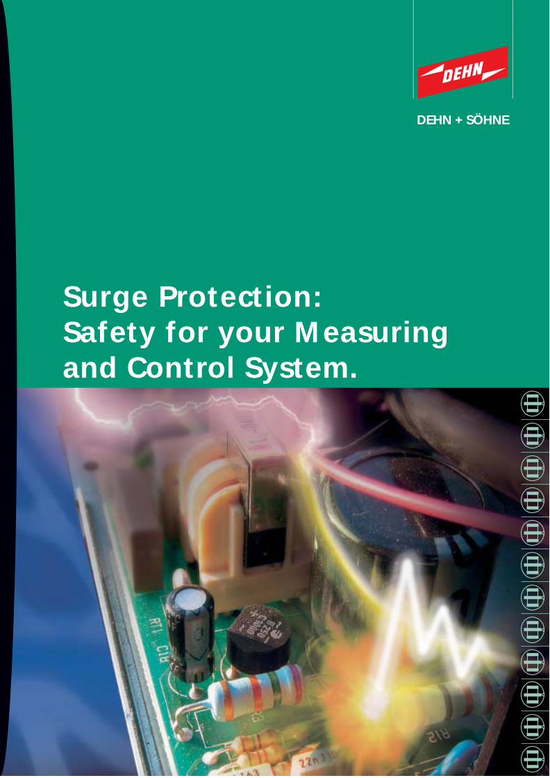
Surge Protection:Safety for your Measuringand Control System.
DS6
63/E
/110
4
© C
OPY
RIG
HT
2004
DEH
N +
SÖ
HN
E
Lightning ProtectionSurge ProtectionSafety Equipment
DEHN + SÖHNEGmbH + Co.KG.Hans-Dehn-Str. 1P.O. Box 164092306 NeumarktGermany
Tel. +49 9181 906-0Fax +49 9181 [email protected]
DEHN + SÖHNE is certified inaccordance with ISO 9001 sothat you can rely on the qualityof our products.
DEHN + SÖHNE offers a widerange of services:
Comprehensive catalogues andpublications with detailed equipment descriptionsDetailed installation instructionsSample specifications for tenders on discTrainings, seminars and practical training fordesigners, engineers and master tradesmenA wide network of foreign agencies
DEHN + SÖHNEDEHN + SÖHNE

Surges - a Hot Thing!
Approximately 24 out of 100 cases of
damage to electronic equipment are
caused by surges. Therefore, surges
are by far the most frequent cause of
damage as shown in a study of over
7,370 cases in Germany!
Anyone who has escaped that event
by now, has either been lucky – seen
from the statistic point of view - or has
made provisions.
Automation - Flexibility - Dependence.
Groundbreaking changes in automation
and control systems have become evident
within the last few years. The increasing
variety of industrial products as well as
flexible utilisation of buildings and in-
stallations require the maximum level of
automation in a line of processes depen-
ding on each other. Therefore, safe and
fast communication among the proces-
ses is an indispensable factor.
A long chain of highly integrated micro-
electronic components is responsible for
transferring the enormous flood of pro-
cess information. As everyone knows, a
chain is as strong as its weakest link. But
what happens if one link of the chain is
broken?
Is it the designer, who intends to project
a trendsetting installation based on the
latest state of the art? Is it the installa-
tion engineer, who has promised to
mount an efficient installation? Or is it
the operator, who is responsible for the
organisation of the process?
It does not matter who is responsible
for a single case, all of them must bear
the consequences: the designer who
could have known it better, the installa-
tion engineer who will get no further
orders and the operator for whom the
damage is hardly repairable.
2 3
Damage to electronic equipment.
23.7% of damage to electronic
equipment is caused by surges.
This shows an analysis of about
7,370 damage claims.Ref: Württembergische Versicherung AG, 2001.
Things are not bound to happen this way...
Surges and their waysinto measuring and control systems.
Surges are momentary peak voltages,
socalled transient voltages, arising for
only some milliseconds. They reach peak
values of up to some 10,000 Volts.
These surges are caused by
direct lightning strokes
indirect lightning strokes within a
distance of up to some kilometres
switching operations within the
power supply system
interferences due to internal switching
operations.
Electronic equipment can be destroyed by
both powerful impulses out of atmosphe-
ric discharges and peak voltages out of
switching operations.
The way of surges into installations is un-
predictable: They interfere with or destroy
equipment by entering the installation via
signal and data lines or power supply lines.
Who is responsible?
It is clear: Electronics insurances cover
the damage to hardware, provided an
insurance was taken out. But who is
responsible for the subsequent damage
caused by data loss, production stand-
still or even personal injury?
Failures are unacceptable for processes.
Surges hit the most sensitive equipment
first, i.e. those responsible for the transmis-
sion of information. These are e.g. program-
ming logic controls (PLCs), control units,
measuring sensors and transmission equip-
ment. If only one link of this chain fails due
to surges, the whole system is paralysed.
The resulting consequences are severe:
production standstill, no receipt or dispatch
of goods, failing emergency circuits, mal-
operation, programme faults and, last but
not least, life hazards.
Surges are the most frequent Cause of Damage.
Theft,Vandalism
27,1%
23,7 %Surges
(lightning discharges andswitching operations)
15,3%Others
0,8 %Elemental
Water 5,6 %
22,9%Carelessness
Fire 4,6 %

Earthing and shielding.
The interfering currents induced by a
lightning stroke should be led in parallel
via as many paths as possible to reduce
the partial currents in the cables/shields.
This can be achieved by building/spatial
shielding and intermeshing all equipo-
tential bonding conductors and earthing
electrodes.
It would be recommendable to take cor-
responding measures already in the
designing phase, like connecting metal
reinforcements in concrete walls as well
as ceilings and floors, combining the
metal façades and connecting these
parts with the down conductor systems
of the external lightning protection
system. The installation of equipotential
bonding bars to be connected to all
conductive parts is an obligatory mea-
sure. Installing copper circumferential
earthing ring conductors in control
rooms, e.g. within the false floor, would
be a good solution.
Adequate treatment of cable shields
is an essential part of the protection
concept. Basically, all shields shall be
connected at both ends – at the control
unit and at the terminal device/measu-
ring sensor – directly or indirectly via
SPDs. If they cross a boundary of a light-
ning protection zone, they have also
to be connected to the equipotential
bonding.
Surge protection in data and power
supply systems
Almost every measuring and control device
needs electrical power for working. In most
cases it is supplied directly from the power
network. Moreover there are many interfa-
ces between measuring and control systems
and data networks (LANs) or telecommuni-
cation networks (WANs). Effective protec-
tion for measuring and control equipment
unifies the treatment of all system interfa-
ces in one protection concept.
Power supply and data networks can be pro-
tected by lightning current arresters, surge
arresters and protective devices especially
adapted to individual applications.
Our documentation provides detailed infor-
mation about the protection concepts and
make the choice of the right SPD easier.
5
Safety in line with economic
Efficiency.
To provide measuring and control systems
with the necessary safety for operation,
requires a protection concept withstan-
ding all loads caused by lightning currents
and surges. It must reduce both the con-
ductively coupled as well as the induc-
tively/capacitively coupled interferences
to harmless values. For this purpose, the
new internationally valid standard DIN
IEC 62305-4 (DIN V VDE V 0185 Part 4)*
recommends the lightning protection
zones concept. Dividing an installation
to be protected into different protection
zones allows to provide a differentiated
but adapted use of protective devices,
even for great measuring and control
installations. This helps to achieve maxi-
mum cost effectiveness. Even for recon-
struction purposes, this protection con-
cept is a safe guide.
Lightning Protection Zones Concept.
The first step is to define the different
lightning protection zones (LPZ). The
sensitive equipment like programming
logic controls, alarm systems or measu-
ring sensors shall be assigned lightning
protection zone 2, at least. Mechanical
distributors like terminal boards and
terminal boxes can also withstand the
loads of lightning protection zone 1.
All electrically conductive parts crossing
a lightning protection zone have to be
protected.
For example, metal pipes and cable ducts
as well as cable shields must be connected
to the equipotential bonding directly at the
boundaries of the protection zones. Live
lines like external conductors of the electri-
cal power supply or communication lines
have to be furnished with surge protective
devices that come up to the requirements
at the installation site.
When choosing the surge protective devices,
both the potential impulse current loads and
the electrical and mechanical requirements
of the boundary have to be considered.
The most effective Protection Concept againstLightning Currents and Surges.
4
Do not hesitate to ask for our publications:
DS 649 E “Surge Protection:
Easy choice“
DS 647 E “Surge Protection: Safety for
Your Data Networks”
*Title:“Protection against lightning electro-magnetic impulse- Part 1: General principles“
Internal ring conductorin accordance with DIN VDE 0800, Part 2.
reinforcement
reinforcement
earthing ring conductor
50 mm2, Cu
M
ventilation
down-conductor
system
spatial shield
terminal device
steel reinforcementIT system
foundation earthing electrode
air-termination system
l.v. power supplysystem
Lightning equipotential bondingLightning current arrester(SPD Type 1)Local equipotential bondingSurge arrester(SPD Type 2, SPD Type 3)
Lightning equipotential bondingLightning current arrester
Local equipotential bondingSurge arrester
Lightning Protection Zones Concept

Capacitive coupling
If lightning hits a neighbouring object, the
potential of the same can rise by several
100,000 V compared to its environment.
The lightning channel has an effect like a
giant capacitor via the air as dielectric
element on adjacent electrically conduc-
tive components. Due to different coupling
capacities, currents of up to several 10 A
arise on the IT lines. The resulting surges
strike through the insulation of the terminal
equipment and let the currents flow to
earth.
As a matter of fact, “well“-shielded cables
can provide a certain protection against
inductive and capacitive interferences and
should therefore be used rather than
unshielded cables. But when is a cable
“well“-shielded in the sense of lightning
and surge protection?
The cable shield must be interconnected
throughout the whole length and earthed
at both ends at least. Only a shield connec-
ted at both ends can limit capacitive and
inductive inteferences.
The shield earthing should be designed
with low impedance. This prevents peak
voltages of many 1,000 V from interfering
with the terminal equipment due to in-
appropriate shield earthing. It is especially
favourable to connect the cable shield to
the equipotential bonding with special
shield terminals, e.g. Type SAK.
The shields of cables between buildings
must be capable of conducting momentarily
high impulse currents. This is only possible
with a shield cross section with sufficient
dimension.
In practice, cables with incomplete shield
cover are used for econcomic reasons. This
results in residual interferences on the signal
lines. This effect can be reduced by a multi-
ply shielded cable.
Conclusion
Using shielded cable material in addition to
lightning current and surge arresters helps to
optimise the protection effect against surges.
Shielded cables alone can reduce interferen-
ces or damage to terminal equipment but not
prevent it. In most cases, the using SPDs is an
indispensable measure.
7
Common-mode interferences
Earthed signal lines, as often used for
measuring and control systems, form an
induction loop. Also RS 485 bus systems
and current loops (e.g. 0-20 mA) are
threatened. Common-mode interferences
are induced from line to earth and can be
up to 10,000 V. Within milliseconds, the
insulation of the terminal devices is stri-
cken through and their inputs and out-
puts are destroyed. Common-mode inter-
ferences are the most frequently arising
type of interference.
Differential-mode interferences
Two-core signal lines, mainly used in telecom-
munication systems, forms an induction loop.
For reasons of line unbalance and different
laying, different voltages are induced into the
two lines. The consequence is a differential-
mode interference (up to several 1,000 V)
between the signal lines – strong enough to
destroy connected terminal devices.
Know the Danger - Avert the Danger.How to eliminate Surges.
6
induction loop
measuring and control line
power supply line
induction loop
measuring and control line
power supply line
EB 1 EB 2measuring and control line
EB 1 measuring and control line
Inductive coupling
Both discharges of lightning strokes via the external lightning protection system and switching
operations or short circuits in electrical power systems generate high interference fields. These
fields can induce destructive impulse voltages up to some 10,000 V and impulse currents of
up to some 1,000 A in signal lines.
Protection measures
There is a way to control the effects of
direct lightning strokes. Surge arresters
capable of carrying lightning currents like
BLITZDUCTOR® CT Type B safely discharge
even partial lightning currents without pro-
blem and without damage to the equip-
ment. In order to reduce interferences on
systems within buildings, the lightning
current arresters should be installed at the
service entrance of the building (boundary
from LPZ 0A to 1).They are connected to the
equipotential bonding at low impedance.
Protection measures
Induced common-mode and differential-
mode interferences can arise anywhere,
also within buildings. By using powerful
surge arresters with a low voltage protec-
tion level, however, the coupled interfe-
rences can be safely controlled and dama-
ge can be avoided. The use of SPDs imme-
diately upstream of the terminal devices
(LPZ 1 or 2) would be recommendable.
Furthermore, it should be ensured that the
area of the induction loop is kept as small
as possible. Parallel installation with an
air-termination system or with power
supply lines must be avoided. In addition, it is
recommended to use shielded or twisted pair
lines.
Shielded cables and their effects
power supply line
shielded measuring and control line
Protection measures
If lightning does not hit the installation directly,
capacitively coupled currents can be discharged
safely and without risk, e.g. via BLITZDUCTOR®
CT M ... . If no further measures are taken, the
use of SPDs immediately upstream of the ter-
minal equipment is recommendable. Further-
more, the capacitive coupling of interferences
can be reduced by using a shielded cable.
Conductive coupling
With a direct lightning stroke, impulse cur-
rents of up to 200,000 A enter the air-termi-
nation system. In this moment the electrical
potential of the building rises enormously.
The consequence are potential differences
up to several 100,000 V on power supply
lines, telecommunication lines and other
measuring and control lines with external
potential. Uncontrolled flashovers in elec-
trical equipment allow destructive partial
lightning currents to flow to earth.
Electrical equipment connected to the lines
within a distance of some kilometres from
the point of strike can be affected. The risk
for measuring and control systems as well
as telecommunication systems installed
between buildings is especially high.

Building services management systems
In modern building installation, high-tech
interconnected control and alarm signal
systems are used. They allow flexible and
supervised control of the technical proces-
ses within the building ... and require surge
protection.
For more information please see pages 10/11.
Analogue measuring
Whether temperatures, weights or liquid
levels – in all fields of industry these kinds
of variables have to be controlled, mostly
via analogue measuring sensors or trans-
mitters ... which should be protected
against surges.
For more information please see pages 14/15.9
Measuring and Control Systems require DEHN Surge Protection.
8
Process control and automation
The level of automation increases
rapidly, especially in process control
and supervision. This, however, is only
possible by interconnecting decentral
components ... and by installing pro-
tection against surges.
For more information please see pages 12/13.
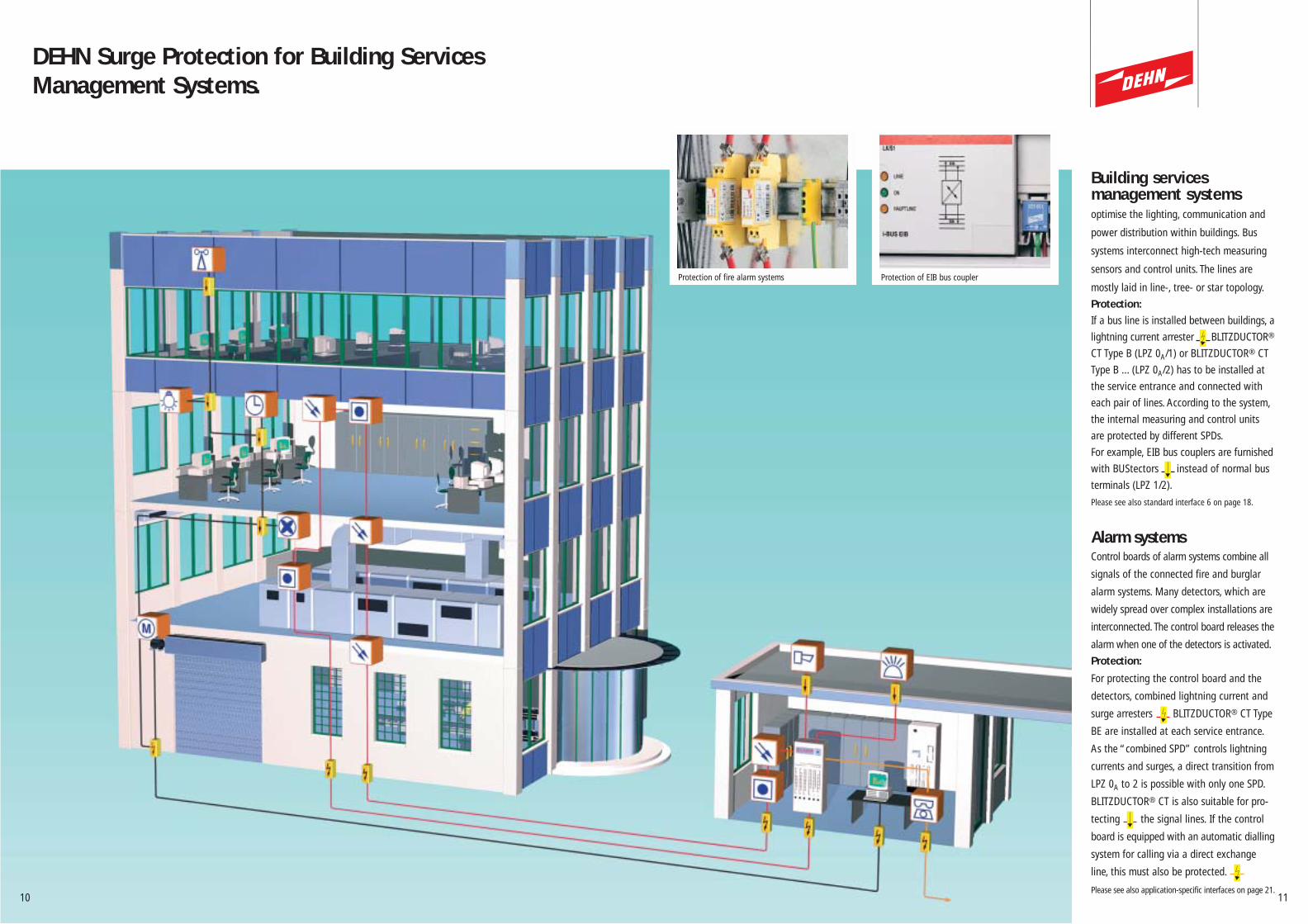
Building services management systemsoptimise the lighting, communication and
power distribution within buildings. Bus
systems interconnect high-tech measuring
sensors and control units. The lines are
mostly laid in line-, tree- or star topology.
Protection:
If a bus line is installed between buildings, a
lightning current arrester BLITZDUCTOR®
CT Type B (LPZ 0A/1) or BLITZDUCTOR® CT
Type B ... (LPZ 0A/2) has to be installed at
the service entrance and connected with
each pair of lines. According to the system,
the internal measuring and control units
are protected by different SPDs.
For example, EIB bus couplers are furnished
with BUStectors instead of normal bus
terminals (LPZ 1/2).
Please see also standard interface 6 on page 18.
Alarm systemsControl boards of alarm systems combine all
signals of the connected fire and burglar
alarm systems. Many detectors, which are
widely spread over complex installations are
interconnected. The control board releases the
alarm when one of the detectors is activated.
Protection:
For protecting the control board and the
detectors, combined lightning current and
surge arresters BLITZDUCTOR® CT Type
BE are installed at each service entrance.
As the “combined SPD” controls lightning
currents and surges, a direct transition from
LPZ 0A to 2 is possible with only one SPD.
BLITZDUCTOR® CT is also suitable for pro-
tecting the signal lines. If the control
board is equipped with an automatic dialling
system for calling via a direct exchange
line, this must also be protected.
Please see also application-specific interfaces on page 21.11
DEHN Surge Protection for Building ServicesManagement Systems.
10
Protection of fire alarm systems Protection of EIB bus coupler

RS 485 - Field Bus interfaceOn the process control level, “high-tech”
components are interconnected via twisted
lines. The requirement for “real-time capa-
bility“ on processes resulted in a develop-
ment of especially fast and therefore sensi-
tive field bus systems. The bus cabling struc-
ture can be extended over several kilometres.
Protection:
Where a bus line enters the building, one
lightning current arrester e.g. BLITZ-
DUCTOR® CT BD HF 5 (LPZ 0A/2) has to be
installed per pair of lines. Shield earthing at
low impedance directly at the protective
device is recommended. For fine protection
of PROFIBUS-DP devices, surge protective
adapter FS 9E PB 6 (LPZ 2/3) is simply
plugged in.
Please see also standard interface 1 on page 17.
Sensor-Actuator interfaceCorrect processing requires a lot of infor-
mation and a number of actions. The sen-
sors record process data and the actuators
control the process.
Protection:
Just as the sensitive control units, also the
production lines are divided into lightning
protection zones. Suitable protective devices
at the zone boundaries (LPZ 1 to 2) limit
upcoming surges. For protecting multi-core
cables, DEHNconnect RK surge protective
terminal blocks are especially suitable.
AS interface, for example, requires an espe-
cially adapted surge protection module.
Please see also standard interface 5 on page 18.
*PLC = Programming Logic Controls13
DEHN Surge Protective Devices for Process Control and Automation Systems.
12
Schutz von SPS-Ein-/Ausgängen Schutz von AS-InterfaceSchutz von PROFIBUS-DP-GerätenProtection of PROFIBUS DP devices Protection of PLC* in-/outputs* Protection of AS interfaces
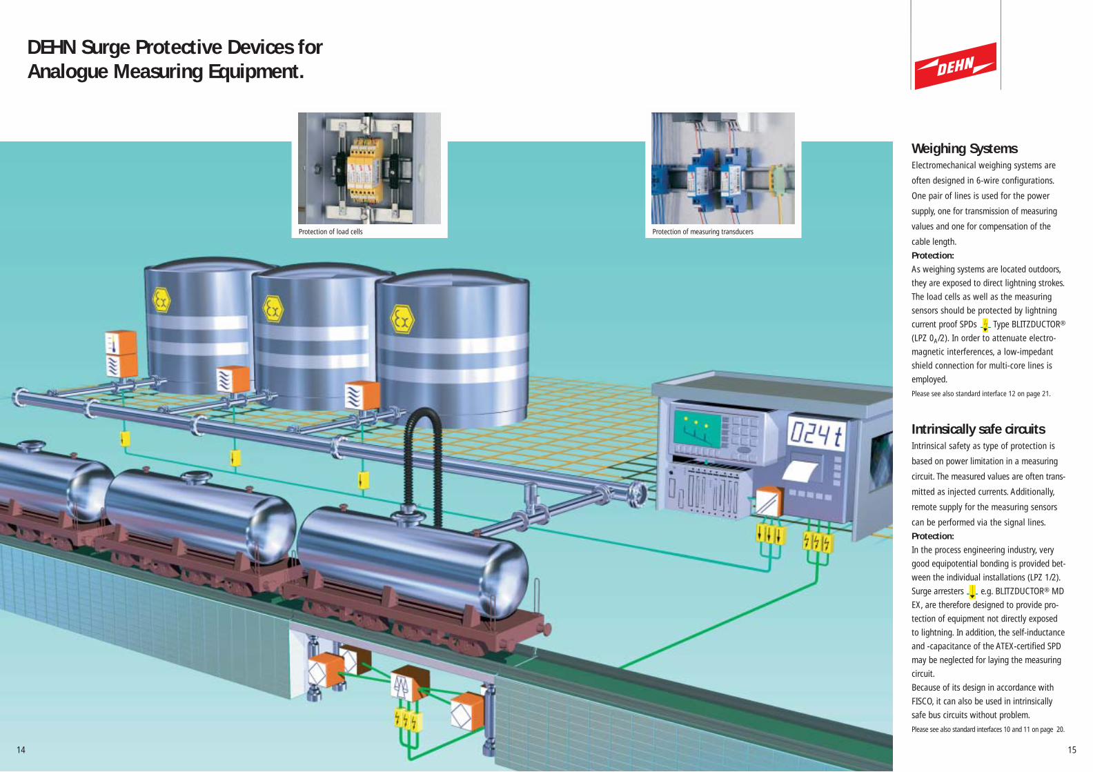
Weighing SystemsElectromechanical weighing systems are
often designed in 6-wire configurations.
One pair of lines is used for the power
supply, one for transmission of measuring
values and one for compensation of the
cable length.
Protection:
As weighing systems are located outdoors,
they are exposed to direct lightning strokes.
The load cells as well as the measuring
sensors should be protected by lightning
current proof SPDs Type BLITZDUCTOR®
(LPZ 0A/2). In order to attenuate electro-
magnetic interferences, a low-impedant
shield connection for multi-core lines is
employed.
Please see also standard interface 12 on page 21.
Intrinsically safe circuitsIntrinsical safety as type of protection is
based on power limitation in a measuring
circuit. The measured values are often trans-
mitted as injected currents. Additionally,
remote supply for the measuring sensors
can be performed via the signal lines.
Protection:
In the process engineering industry, very
good equipotential bonding is provided bet-
ween the individual installations (LPZ 1/2).
Surge arresters e.g. BLITZDUCTOR® MD
EX, are therefore designed to provide pro-
tection of equipment not directly exposed
to lightning. In addition, the self-inductance
and -capacitance of the ATEX-certified SPD
may be neglected for laying the measuring
circuit.
Because of its design in accordance with
FISCO, it can also be used in intrinsically
safe bus circuits without problem.
Please see also standard interfaces 10 and 11 on page 20.
15
DEHN Surge Protective Devices for Analogue Measuring Equipment.
14
Protection of measuring transducers Protection of load cells

FS 9E PBPlug-in surge protective adapter for fine
protection at the interface of terminal
equipment.
Part No. 924 017
17
Our advice:
The following standard interfaces show
examples for arrester circuits to protect
communication/signal interfaces.
Please note that both information tech-
nology system and the power supply
system must be integrated in the equi-
potential bonding system to provide
efficient surge protection.
BLITZDUCTOR® CT2-pole, universal lightning current/surge
arrester in terminal block design.
BLITZDUCTOR® CT BD HF 5V
Part No. 919 506 + 919 670
BLITZDUCTOR® CT B 110V
Part No. 919 506 + 919 510
BLITZDUCTOR® CT MD HF 5V
Part No. 919 506 + 919 570
Selection Aid for Standard Interfaces with DEHN Surge Protective Devices.
16
1
2
3
BLITZDUCTOR® VT RS485Surge protective device for measuring and
control systems and equipment with 4-wire
data transmission.
Part No. 918 401
The numbers refer to theexact description of theprotective device and itscorresponding part number.Please find them in thedescriptions above.
Profibus-DP, up to 12 MBit/s
Interface 1
BLITZDUCTOR CT
FS 9E PB
1
RS 485, RS 422, V.11, 4-wire systems
Interface 4
BLITZDUCTOR CT
USD 15 V11 S B
2
BLITZDUCTOR CT2
BLITZDUCTOR VT RS485
RS 485-Bus, 2-wire systems up to 1 MBit/s
Interface 3
BLITZDUCTOR CT
BLITZDUCTOR CT
BLITZDUCTOR CT2
3
3
Simatic-Net-Profibus, up to 12 MBit/s
BLITZDUCTOR CT
BLITZDUCTOR CT
BLITZDUCTOR CT2
3
Interface 2
3
USD 15 V11 S BPlug-in surge protective adapter for protec-
tion at the interface of terminal equipment.
Part No. 924 051
®
®
® ®
®
® ®
®
®
®

19
AS-i Surge ProtectionModule Protection module for sections of
systems and equipment in AS-i systems.
Part No. 925 010
BLITZDUCTOR® CT2-pole universal lightning current/surge
arrester in terminal block design.
BLITZDUCTOR® CT B 110V
Part No. 919 506 + 919 510
BLITZDUCTOR® CT BE C 24V
Part No. 919 506 + 919 662
BLITZDUCTOR® CT ME 30V
Part No. 919 506 + 919 524
BLITZDUCTOR® CT BE 30V
Part No. 919 506 + 919 624
BLITZDUCTOR® CT MD 48V
Part No. 919 506 + 919 545
Selection Aid for Standard Interfaces with DEHN Surge Protective Devices.
18
4
2
5
6
7
DEHNconnect RK 2-pole surge protective terminal
block
DCO RK ME 24V
Part No. 919 921
DCO RK MD 48V
Part No. 919 942
5
7
The numbers refer to theexact description of the protective device and its corresponding part number.Please find them in thedescriptions beside.
TTY with optocoupler input
Interface 7
BLITZDUCTOR CT
2-wire systems
4
BLITZDUCTOR CT2
BLITZDUCTOR® VT TTYBLITZDUCTOR® CT2
4-wire systems
0-20 mA / 4-20 mA (24 V+30 V)
Interface 8
BLITZDUCTOR CT or
DEHNconnect RK
5
BLITZDUCTOR CT
BLITZDUCTOR CT
LON, FTT 10 and LPT 10 up to 1A
Interface 9
BLITZDUCTOR CT2 BLITZDUCTOR CTor
DEHNconnect RK
7
EIB
Interface 6
BLITZDUCTOR CT2
BUStector
AS Interface
Interface 5
AS-i surge protection module
2
6
®
®
®®
®
®
®
BLITZDUCTOR® VT TTYSurge protective device for measuring
and control systems and equipment
with 4-wire data transmission.
Part No. 918 400
DEHNpipeSurge arrester for screwing into
process field devices, M20 x 1.5
DPI MD 24 M 2S
Part No. 929 941
DEHNpipe
For process field devices
BUStector Surge protective bus terminal in
accordance with EIBA requirements.
Part No. 925 001
®

Application-specificinterfacesDEHN provides a documentation of
application-specific interfaces for the
customers. This documentation is ampli-
fied and updated at regular intervals.
It comprises information about surge
protection measures for power supply
and information technology systems as
well as equipotential bonding measures.
The latest overview can be downloaded
from our website www.dehn.de
Seminar about SurgeProtection Systems"Lightning and Surge Protection for
Measuring and Control Systems"
The seminar is to enhance your knowledge
of lightning and surge protection.
Protection concepts according to the current
state of standardisation are discussed for
electrical and electronic systems. The main
topics are lightning equipotential bonding
and surge protection. The parameters for the
choice of protective devices are explained
and possible concepts are worked out.
For more information about our semi-
nars, topics, dates and locations please
contact the responsible representative
in your country. They shall be pleased
to provide you with the requested
information.
21
BLITZDUCTOR® CT 2-pole universal lightning current/surge
arrester in terminal block design.
BLITZDUCTOR® CT BE 12V
Part No. 919 506 + 919 621
BLITZDUCTOR® CT MD EX 30V2-pole surge arrester in terminal block
design for intrinsically safe circuits and
bus systems. Designed according to FISCO.
BLITZDUCTOR® CT MD EX 30
Part No. 919 507 + 919 581
BLITZDUCTOR® CT MD EX HFD 6
Part No. 919 507 + 919 583
DEHNconnect RK MD EX 24V 2-pole surge protective terminal block
for intrinsically safe circuits. Designed
according to FISCO.
Part No. 919 960
Selection Aid for Standard Interfaces with DEHN Surge Protective Devices.
20
Intrinsically safe circuits with tightly intermeshedequipotential bonding
Interface 10
DEHNpipe MD EXor
DEHNconnect RK MD EXor
BLITZDUCTOR CT MD EX
No Ex zone Ex zone
Interface 11
BLITZDUCTOR CT MD EX
No Ex zone Ex zone
9
BLITZDUCTOR CT
Weighing system in 6-wire configuration
Interface 12
®
®
Control board
DEHNpipeSurge arrester for screwing into pro-
cess field devices, M20 x 1.5. For in-
trinsically safe circuits according to
FISCO.
DPI MD EX 24 M 2
Part No. 929 960
8
9
8 9 ®
Intrinsically safe RS 485 bus system with tightlyintermeshed equipotential bonding
Field Side with Remote 110
DEHNconnect RK MD EXor
BLITZDUCTOR CT MD EX ®
Control board Field side with Remote 110
The numbers refer to theexact description of the protective device and its corresponding part number.Please find them in the descriptions above.

USDPlug-in surge protective adapter, availablewith D-Sub plug and socket connector orwith data cable and plug.
Specific protective circuit for D-Subinterface, 9-, 15, or 25-pole version For high transmission rates
Examples:USD 15 V11 S B Part No. 924 051USD 25 TTY B S(for TTY) Part No. 924 048
AS-i Surge ProtectionModuleSurge Arrester Protection module according to AS-istandard for devices or single instal-lation sections in AS-i systems.Protection of AS-i transmission linesand power supply lines.
2 LEDs indicate the readiness foroperation of the device.For mounting on FK-E- or PG-E- coupling modulesNo bus address required
Part No. 925 010FSPlug-in surge protective adapter designedfor installation directly upstream of theterminal equipment.
Specific protective circuit for D-Subinterface, 9-, 15-, or 25-pole unitFor high transmission ratesFS 9E PB Part No. 924 017FS 15 E(for RS 485/422,V.11) Part No. 924 016
23
BLITZDUCTOR® CTLightning current/Surge arrester 2-pole universal surge protective deviceof the Yellow/Line family in terminal blockdesign. Pluggable, coordinated protectivedevices:Lightning current arrester, combined lightning current and surge arrester(w = 12 mm, h = 58 mm).
Univeral Base PartFor use as feed-through terminal forsupporting the protection modulesNo signal interruption duringinstallation of the moduleIntegrated shield terminal with director indirect shield earthing (accessories)Safe earthing and quick installationwith snap-on foot
Standard unit (yellow) Part No. 919 506
For intrinsically safe circuits (blue)Part No. 919 507
Adapted Protection ModulesCascaded use of SPDs without requi-ring additonal cable lengthsProtection module for intrinsicallysafe circuits, ATEX certification:EEx ia IIC T6
Suitable Protection Modules forLightning Currents B Part No. 919 510BE 12V Part No. 919 621BE 30V Part No. 919 624BE C 24V Part No. 919 662BD HF 5V Part No. 919 670
Suitable Protection Modules for SurgesME 30V Part No. 919 524MD 48V Part No. 919 545MD HF 5V Part No. 919 570MD EX 30V (blue) Part No. 919 581MD EX HFD 6V (blue) Part No. 919 583
Surge Protection with DEHN Equipment.Safety for your Measuring and Control Systems.
22
DEHN Surge Protection is a completesystem ...
....a system for performing complex
lightning protection zones concepts as
well as protection concepts for local
protection requirements. Moreover, the
SPDs of our Yellow/Line product family
provide energy-coordinated protection
with protective effects adapted to the
requirements of your terminal equipment.
...your safety is our concern.
BUStectorSurge ArresterProtective device for EIB in bus terminaldesign according to the requirements ofEIBA
Small design (approx. 11 mm x 11 mm x 11 mm)European Patent
Part No. 925 001
BLITZDUCTOR® VTSurge ArresterCompact surge protective device of theYellow/Line family for installation intoengineering systems and equipment with4-wire data transmission (h = 58 mm).
BLITZDUCTOR® VT TTYProtection for current interfaces Decoupling resistors at the outputallow a direct use of optocouplers
Part No. 918 400
BLITZDUCTOR® VT RS485Protection for RS 485/422- and V.11interfacesShield earthing directly or indirectlyvia integrated gas discharge tube
Part No. 918 401
DEHNconnect RKSurge protective terminal block 2-pole terminal with integrated two-stagesurge protection.
WAGO Cage ClampSlim design (w = 6 mm)Safe earthing via snap-on foot
DCO RK ME 24 Part No. 919 921DCO RK MD 48V Part No. 919 942 DCO RK MD EX 24V Part No. 919 960CoverAD DCO RK GE (yellow) Part No. 919 979AD DCO RK BL (blue) Part No. 919 978
DEHNpipeSurge ArresterWater-proof and corrosion-resistant protec-tive device for outside areas to be screwedinto process field devices with 2-conductormeasuring (e.g. 4-20 mA).Also suitable for retrofitting as it is installedbetween the process field device and thecable gland (not included in delivery).
DPI MD 24 M 2S Part No. 929 941DPI MD EX 24 M 2 Part No. 929 960

DEHN + SÖHNE provides onlyhigh-quality devices – as safety isalways a matter of confidence.
Because of our quality-relatedthinking, closeness to customersand a diversified service pro-gramme, DEHN + SÖHNE is yourreliable partner for safety. Thisis confirmed by our leading co-operation with numerous nationaland international standardizationcommittees. Due to innovativepractical developments in all fieldsof Lightning and Surge Protection,we offer solutions for the EMC-orientated Lightning ProtectionZones Concept.DEHN + SÖHNE always bringsin the latest results of scientificresearch in order to come up tothe customers‘ requirements.
More InformationI would like to have more informationabout the following topics:
Main Catalogue “Surge Protection”
DS 614 E: “DEHN stops Surges”
DS 649 E: “RedLine: ... Easy Choice”
DS 647 E: “Safety for your data networks ”
Please arrange for a visit of one of yourSales Engineers (by appointment)
Name
Company
Address
Country
Phone / Fax
Please fill in and send to us!
Surge Protection:Safety for your Measuringand Control System.
DS6
63/E
/110
4
© C
OPY
RIG
HT
2004
DEH
N +
SÖ
HN
E
Lightning ProtectionSurge ProtectionSafety Equipment
DEHN + SÖHNEGmbH + Co.KG.Hans-Dehn-Str. 1P.O. Box 164092306 NeumarktGermany
Tel. +49 9181 906-0Fax +49 9181 [email protected]
DEHN + SÖHNE is certified inaccordance with ISO 9001 sothat you can rely on the qualityof our products.
DEHN + SÖHNE offers a widerange of services:
Comprehensive catalogues andpublications with detailed equipment descriptionsDetailed installation instructionsSample specifications for tenders on discTrainings, seminars and practical training fordesigners, engineers and master tradesmenA wide network of foreign agencies
DEHN + SÖHNEDEHN + SÖHNE