surface velocity radar -...
TRANSCRIPT
S Pro II SVR Surface Velocity Radar
Owner’s Manual
Dear Valued Radar Customer:
Thank you for choosing the S SVR Radar System. We sincerely appreciate you purchasing the S and giving us the opportunity of serving you and your organization. You will find the S to be an invaluable tool in water management. Most importantly, we care about you, our customer, and want you to be completely satisfied. Our success as a company depends upon your satisfaction and experience with the S Radar. Applied Concepts, Inc. believes that the S offers more than superior performance and versatility. S is backed 100% with reliable, professional, and experienced sales and service support, ready to assist you at your request. We also offer the longest warranty in the industry, with nationwide factory authorized repair centers to assure you of fast and efficient service. We wish you the greatest success in your water management program. Please do not hesitate to let us know if there is anything we may do to add to your product satisfaction. Thanks again!
Sincerely, Applied Concepts, Inc.
ii

Any changes or modifications not expressly approved by Stalker Radar / Applied Concepts, Inc., could void the user’s authority to operate the Stalker Pro II SVR.
Not intended for Law Enforcement use.
S RADAR Stalker/Applied Concepts
2609 Technology Drive Plano, TX 75074 1-888-STALKER
(972) 398-3780 Sales (972) 398-3781 Fax
www.stalkerradar.com
iii

iv
Table of Contents
Introduction ..................................................................................................................... - 1 - What's Included ............................................................................................................... - 2 - Controls and Indicators ................................................................................................... - 3 - Detailed Instructions ....................................................................................................... - 5 -
Providing Power to the Pro II SVR............................................................................. - 5 - Menu Mode ................................................................................................................. - 5 - Recall Mode ................................................................................................................ - 6 - Measurement Mode .................................................................................................... - 6 - Operating the Radar .................................................................................................... - 7 -
Setting Up the Radar Unit ............................................................................................... - 8 - The Operator Menu ..................................................................................................... - 8 - The Option Menu ...................................................................................................... - 10 -
Battery Information ....................................................................................................... - 14 - Angle Errors .................................................................................................................. - 16 - Interference Problems ................................................................................................... - 18 -
Why Testing is important.......................................................................................... - 19 - Pro II SVR Accessories ................................................................................................ - 19 - Service Information ...................................................................................................... - 20 - Specifications ................................................................................................................ - 21 - Serial Communications Protocol .................................................................................. - 22 -
Physical Interface ...................................................................................................... - 22 - Serial Port Message Formats .................................................................................... - 22 -
- 1 -
S Pro II SVR Operator Manual
Introduction
Congratulations! You have purchased the most accurate SVR gun system available. The Stalker Pro II SVR radar was designed specifically to measure the speed of water movement in rivers and streams. The S Pro II SVR is a Ka-band Surface Velocity Radar designed to allow maximum flexibility in measuring water flow. The Angle Sensing ability of the S Pro II SVR allows the radar to automatically compensate for tilt and thus for cosine error. Utilizing a state-of-the-art Digital Signal Processor (DSP), S Pro II SVR provides a level of performance, convenience, and accuracy previously unavailable. The DSP performs the critical filtering and timing functions required for speed measurement in its software, as opposed to hardware. This provides less unit-to-unit variation, more reliable performance, and easier maintenance. One of the unique features of the S Pro II SVR is that it can be upgraded in the future by simply installing new software, preventing obsolescence! S Pro II SVR operates in the Ka- 34.7 GHz band.
- 2 -
S Pro II SVR Operator Manual
What's Included
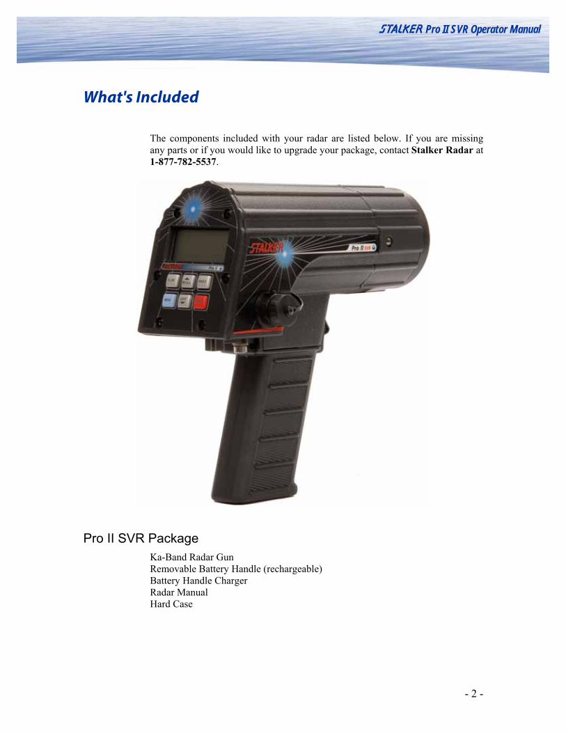
The components included with your radar are listed below. If you are missing any parts or if you would like to upgrade your package, contact Stalker Radar at 1-877-782-5537.
Pro II SVR Package Ka-Band Radar Gun Removable Battery Handle (rechargeable) Battery Handle Charger Radar Manual Hard Case
- 3 -
S Pro II SVR Operator Manual
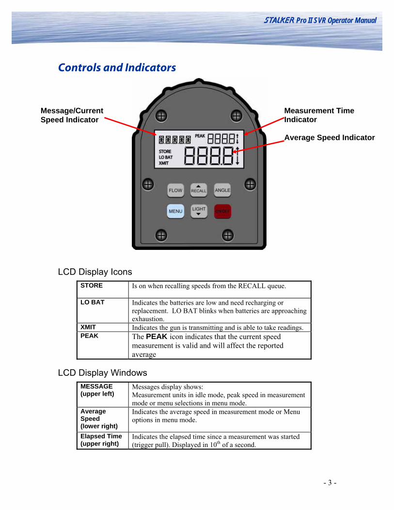
Controls and Indicators
Measurement Time Indicator Average Speed Indicator
Message/Current Speed Indicator
LCD Display Icons STORE Is on when recalling speeds from the RECALL queue.
LO BAT Indicates the batteries are low and need recharging or
replacement. LO BAT blinks when batteries are approaching exhaustion.
XMIT Indicates the gun is transmitting and is able to take readings. PEAK The PEAK icon indicates that the current speed
measurement is valid and will affect the reported average
LCD Display Windows MESSAGE (upper left)
Messages display shows: Measurement units in idle mode, peak speed in measurement mode or menu selections in menu mode.
Average Speed (lower right)
Indicates the average speed in measurement mode or Menu options in menu mode.
Elapsed Time (upper right)
Indicates the elapsed time since a measurement was started (trigger pull). Displayed in 10th of a second.
- 4 -
S Pro II SVR Operator Manual
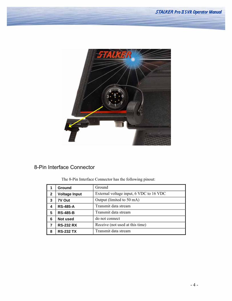
8-Pin Interface Connector
The 8-Pin Interface Connector has the following pinout:
1 Ground Ground 2 Voltage Input External voltage input, 6 VDC to 16 VDC 3 7V Out Output (limited to 50 mA) 4 RS-485-A Transmit data stream 5 RS-485-B Transmit data stream 6 Not used do not connect 7 RS-232 RX Receive (not used at this time) 8 RS-232 TX Transmit data stream

- 5 -
S Pro II SVR Operator Manual
Detailed Instructions Providing Power to the Pro II SVR
Batteries - The Pro II SVR handle is a removable, rechargeable lithium ion battery. Attach the battery handle to the radar body by inserting the front tip of the handle into its mating lip on the radar body and rotating the back of the handle up until seated. Next, rotate the thumb latch to engage the ramping slot in the back of the handle. When fully charged, the handle will power the gun for more than 3 hours of continuous transmit time. The handle can be removed and recharged using the included charger. It can also be charged while attached to the gun when using the optional 12VDC Cigar Cable for external power.
External - To power the Pro II SVR from an external 12VDC (nominal)
source, use the optional 12VDC Cigar Cable attached to the 8-pin interface connector on the side of the gun. The 12VDC cigar cable also charges the battery handle while it is supplying power to the radar.
Turning the Transmitter ON and OFF The radar transmitter must be turned ON to make a measurement. Trigger Transmit – The transmitter toggles between ‘on’ and ‘off’ states by
squeezing the trigger. If the unit is ‘off’, squeezing the trigger turns it ‘on’. If it is ‘on’, squeezing it again will turn it off.
NOTE:
* The XMIT icon displays when the gun IS transmitting. * The XMIT icon does not display when the gun IS NOT transmitting.
MPHPEAK
XMIT
Menu Mode This mode is activated by pressing the MENU key. Press once to access the Operator Menu. Access the Option Menu by pressing and holding the MENU key from the Operator Menu. In either menu mode, the MENU button advances to the next section and the UP/DOWN buttons cycle through the available options. See “Setting up the Radar Unit” for more detailed instructions on how to use the menu system.

- 6 -
S Pro II SVR Operator Manual
Recall Mode This mode is active by default. It is, in effect, the idle mode. Pressing the RECALL button cycles through the 10 previous measurements. STORE indicates this mode is in effect.
Recall Mode Button Functions Trigger FLOW Select water flow direction sensitivity mode (Outbound,
Inbound, Auto) ▲/RECALL Cycle through previous readings stored in volatile memory
ANGLE Cycle through horizontal cosine angles MENU Enter Menu Mode
LIGHT/▼ Toggle the LCD backlight and the keyboard backlight on and off
ON / OFF Toggle the main power On and Off
Measurement Mode
This mode is activated by Trigger. It is the active measurement mode. Pressing Trigger again completes the measurement and exits Measurement Mode, storing the result in the Recall list.
Measurement Mode Button Functions
Trigger Terminate measurement and return to Recall Mode FLOW First press: display current setting, subsequent presses: cycle
through flow direction mode settings, returns to basic Measurement Mode on timeout or other key press—measurement is restarted by changing the direction setting
▲/RECALL -none- ANGLE First press: display current horizontal angle setting,
subsequent presses: cycle through horizontal angles from 0° to 60° in 5° increments, long key press decrements angle, returns to basic Measurement Mode on timeout or other key press—measurement continues, but if angle is changed the measurement is restarted
MENU Abort measurement and enter Menu Mode LIGHT/▼ Toggle the LCD backlight and the keyboard backlight on and
off
ON / OFF Toggle the main power On and Off

- 7 -
S Pro II SVR Operator Manual
Operating the Radar The Pro II SVR is powered on by pressing the red ON/OFF button on the rear panel of the radar.
Operator Actions SVR Display Unit
When first powered on, the S Pro II SVR displays its RECALL screen and is in “idle (Recall) mode.”
Pressing and releasing the trigger initiates Measurement Mode or “active mode.”
Pressing and releasing the trigger a second time stores current measurement.
Pressing the RECALL button allows the operator to scroll through the stored measurements (up to 10).
Stored measurement #3 is shown recalled
Pressing and releasing the trigger re-initiates Measurement Mode.
- 8 -
S Pro II SVR Operator Manual
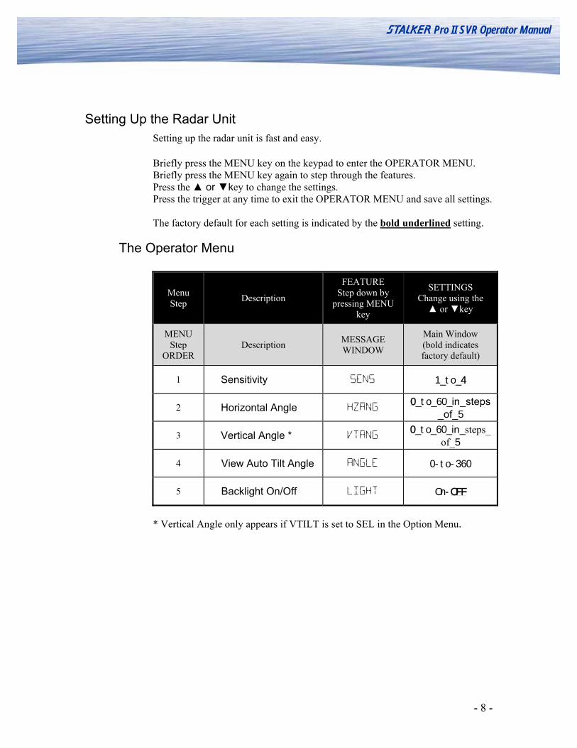
Setting Up the Radar Unit Setting up the radar unit is fast and easy.
Briefly press the MENU key on the keypad to enter the OPERATOR MENU. Briefly press the MENU key again to step through the features. Press the ▲ or ▼key to change the settings. Press the trigger at any time to exit the OPERATOR MENU and save all settings. The factory default for each setting is indicated by the bold underlined setting.
The Operator Menu
Menu Step Description
FEATURE Step down by
pressing MENU key
SETTINGS Change using the ▲ or ▼key
MENU Step
ORDER Description MESSAGE
WINDOW
Main Window (bold indicates factory default)
1 Sensitivity SENS 1_to_4
2 Horizontal Angle HZANG 0_to_60_in_steps
_of_5
3 Vertical Angle * VTANG 0_to_60_in_steps_
of_5
4 View Auto Tilt Angle ANGLE 0-to-360
5 Backlight On/Off LIGHT On-OFF
* Vertical Angle only appears if VTILT is set to SEL in the Option Menu.

- 9 -
S Pro II SVR Operator Manual
Sensitivity Setting The Sensitivity setting affects the range (measuring distance) of the radar. The settings are:
4
Setting the range to 4 increases the gun’s sensitivity and lengthens the measuring distance. It “looks” as far away as possible for targets and gives the gun the highest level of performance. This is the default setting.
2, 3 Setting the range to 2 or 3 sets the gun to a medium range in its measurement distance.
1
Setting the range to 1 decreases the gun’s sensitivity and shortens its measurement distance. The 1 range setting is handy for measuring objects close to the gun and when you want to restrict the gun from “seeing” objects farther out in the background.
Horizontal Angle Use this menu selection to specify the horizontal angle of intercept to the direction of flow of the water being measured. The angle can be set from to 0 to 60 degrees in 5 degree increments. Refer to the section at the end of this users manual for an explanation of the effect of measuring speed at an angle relative to the direction of travel and how this adjustment can compensate for that angle.
Vertical Angle Use this menu selection to specify the vertical angle of intercept to the direction of flow of the target being measured. This is only required when the users has set the Tilt Sensor to SEL in the options menu. If the Tilt Sensor was set to Auto, then the vertical angle is taken care of by the internal Tilt Sensor and this menu selection is not available.
View Auto Tilt This menu selection will show the current tilt sensor angle reading. It can be used for test verification or manual data recording.
Backlight On/Off This menu selection toggles the back light between on and off.

- 10 -
S Pro II SVR Operator Manual
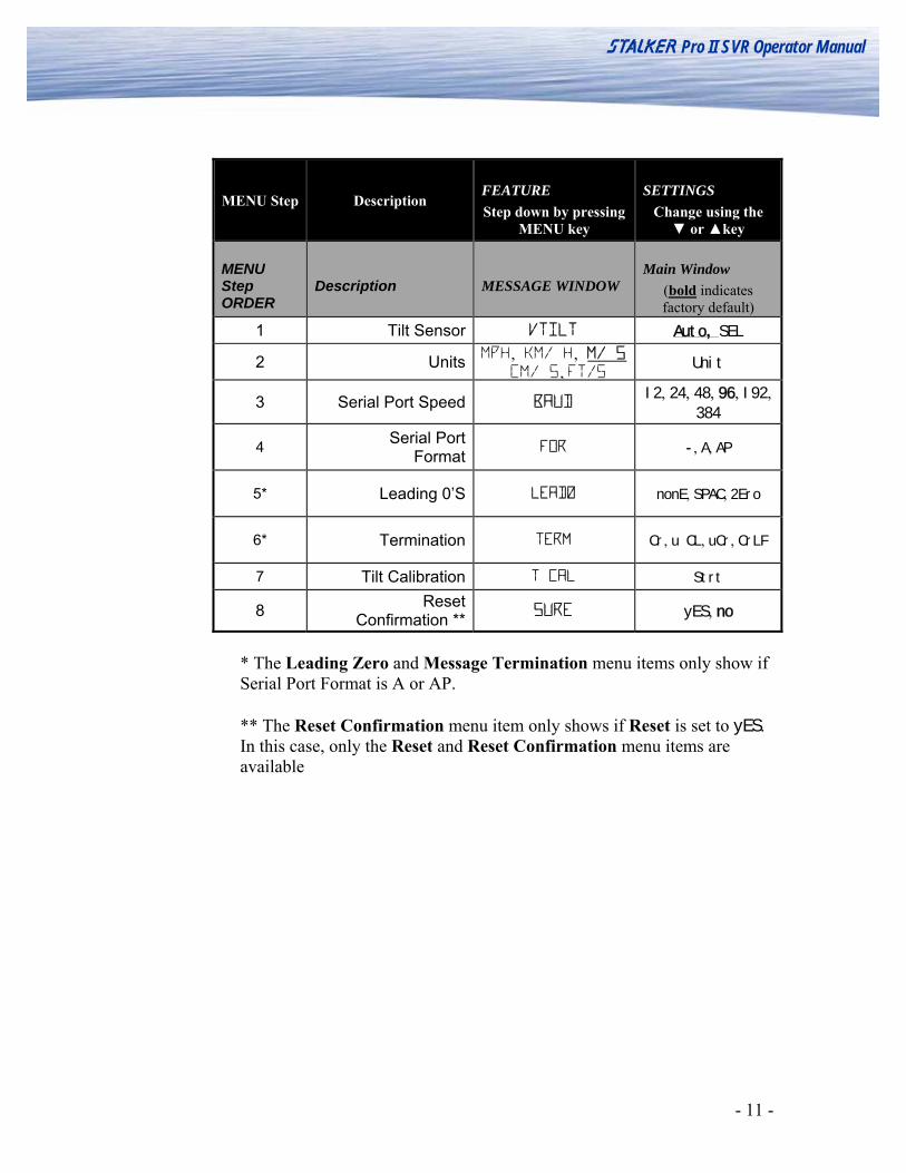
The Option Menu
Selecting Options Selecting the options is more involved (but still easy), because there are 8 features to select. The Pro II SVR ships with the default (BOLD) settings indicated in the chart.
Enter the OPERATOR MENU as described on the previously. Press and hold the MENU key (while in the OPERATOR MENU) to enter the OPTION MENU. All display segments will briefly flash to indicate the change of menu.
Briefly press the MENU key again to step through the FEATURES. The current feature selected is shown in the top left corner of the display. The ▲ and ▼ keys are used to change the setting of each option. The current setting selected is shown in the center of the display. Press the trigger at any time to exit the OPTION MENU, save all settings and return to normal operation.
Press and hold the MENU key to return to the OPERATOR MENU. All display segments will flash to indicate the change of menu. The factory default for each setting is indicated by the bold underlined setting.
- 11 -
S Pro II SVR Operator Manual
MENU Step Description FEATURE Step down by pressing
MENU key
SETTINGS Change using the
▼ or ▲key
MENU Step ORDER
Description MESSAGE WINDOW Main Window
(bold indicates factory default)
1 Tilt Sensor VTILT Auto, SEL
2 Units MPH, KM/ H, M/ S CM/ S, FT/S Unit
3 Serial Port Speed BAUD I2, 24, 48, 96, I92,
384
4 Serial Port Format FOR -, A, AP
5* Leading 0’S LEAD0 nonE, SPAC, 2Ero
6* Termination TERM Cr, u CL, uCr, CrLF
7 Tilt Calibration T CAL Strt
8 Reset Confirmation ** SURE yES, no
* The Leading Zero and Message Termination menu items only show if Serial Port Format is A or AP. ** The Reset Confirmation menu item only shows if Reset is set to yES. In this case, only the Reset and Reset Confirmation menu items are available
- 12 -
S Pro II SVR Operator Manual
el: Uses angle provided by the user in the Vertical Angle menu for vertical angle adjustments.
nits
ress the trigger to exit the Option enu.
Hour
econd
FT/S: Feet per Second
erial Port Speed
Options Defined
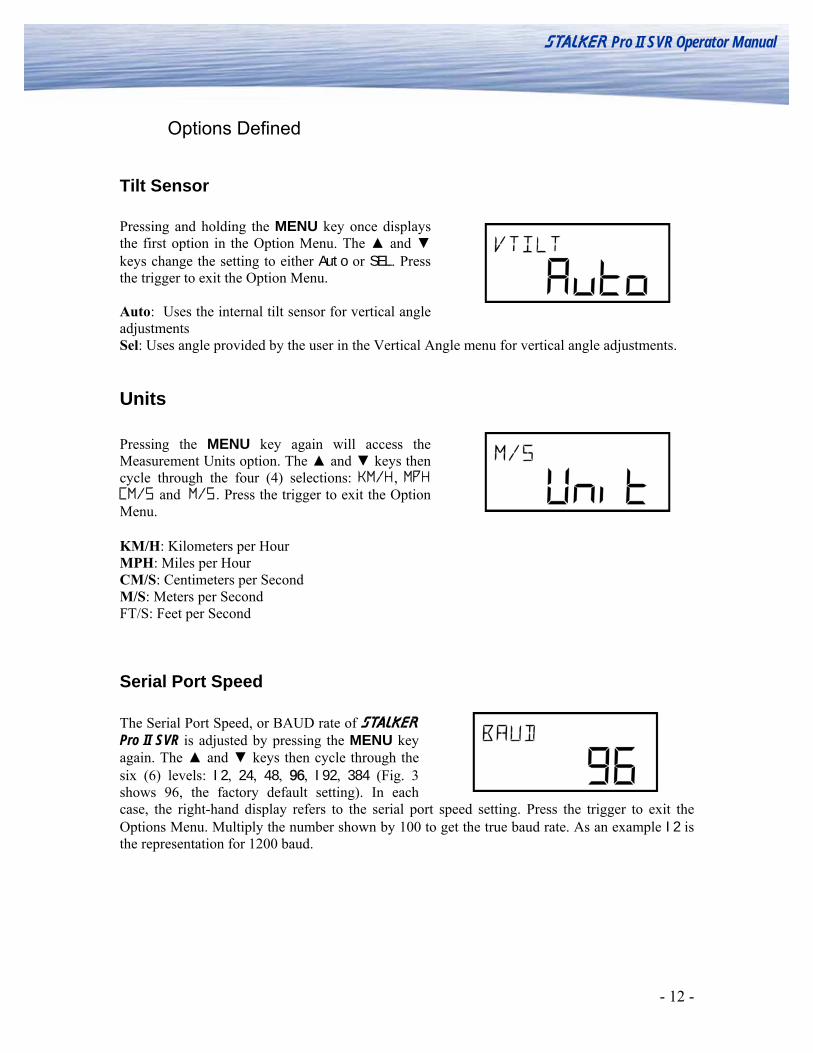
Tilt Sensor Pressing and holding the MENU key once displays the first option in the Option Menu. The ▲ and ▼ keys change the setting to either Auto or SEL. Press the trigger to exit the Option Menu. Auto: Uses the internal tilt sensor for vertical angle adjustments S
U Pressing the MENU key again will access the Measurement Units option. The ▲ and ▼ keys then cycle through the four (4) selections: KM/H, MPH CM/S and M/S. PM KM/H: Kilometers per MPH: Miles per Hour CM/S: Centimeters per SM/S: Meters per Second
S The Serial Port Speed, or BAUD rate of S Pro II SVR is adjusted by pressing the MENU key again. The ▲ and ▼ keys then cycle through the six (6) levels: I2, 24, 48, 96, I92, 384 (Fig. 3 shows 96, the factory default setting). In each case, the right-hand display refers to the serial port speed setting. Press the trigger to exit the Options Menu. Multiply the number shown by 100 to get the true baud rate. As an example I2 is
e representation for 1200 baud.
th
- 13 -
S Pro II SVR Operator Manual
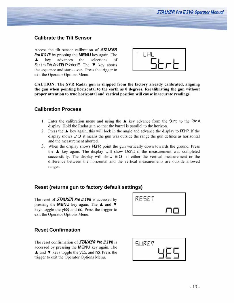
Calibrate the Tilt Sensor Access the tilt sensor calibration of S Pro II SVR by pressing the MENU key again. The ▲ key advances the selections of Strt PArA PErP donE. The ▼ key aborts the sequence and starts over. Press the trigger to exit the Operator Options Menu. CAUTION: The SVR Radar gun is shipped from the factory already calibrated, aligning the gun when pointing horizontal to the earth as 0 degrees. Recalibrating the gun without proper attention to true horizontal and vertical position will cause inaccurate readings.
Calibration Process
1. Enter the calibration menu and using the ▲ key advance from the Strt to the PArA display. Hold the Radar gun so that the barrel is parallel to the horizon.
2. Press the ▲ key again, this will lock in the angle and advance the display to PErP. If the display shows ErOr it means the gun was outside the range the gun defines as horizontal and the measurement aborted.
3. When the display shows PErP, point the gun vertically down towards the ground. Press the ▲ key again. The display will show DonE if the measurement was completed successfully. The display will show ErOr if either the vertical measurement or the difference between the horizontal and the vertical measurements are outside allowed ranges.
Reset (returns gun to factory default settings) The reset of S Pro II SVR is accessed by pressing the MENU key again. The ▲ and ▼ keys toggle the yES, and no. Press the trigger to exit the Operator Options Menu.
Reset Confirmation The reset confirmation of S Pro II SVR is accessed by pressing the MENU key again. The ▲ and ▼ keys toggle the yES, and no. Press the trigger to exit the Operator Options Menu.

- 14 -
S Pro II SVR Operator Manual
Battery Information
The Pro II SVR uses a rechargeable Lithium Ion battery handle. Attach the battery handle to the radar body by inserting the front tip of the handle into its mating lip on the radar body and rotating the back of the handle up until seated. Next, rotate the thumb latch to engage the ramping slot in the back of the handle.
Operational Time using the Battery Handle The Pro II SVR draws the most current when it is transmitting, so the run time depends upon how often the gun is transmitting. The Pro II SVR also has a sleep mode to conserve battery life when it is not being operated. The sleep mode is automatically initiated after about 10 seconds of inactivity when the transmitter is off. Squeezing the trigger or pressing any key immediately “wakes” the gun and brings it back into operation.
Operational Status Run Time Continuous Transmitting 3.0 Hours Typical Trigger Operation 6-7 Hours
Low Battery Warning A low voltage condition from either the battery or an external power source will cause the LO BAT icon to illuminate and will inhibit speed readings.
Charging the Battery Handle The Battery Handle Charger is used to charge the battery handle for the Pro II SVR. This charger may be powered either from 120 VAC using the wall adapter supplied or from a 12 VDC vehicle electrical system by using the optional cigarette plug cable. To use the charger, plug either the wall adaptor or the optional cigarette plug cable into the 12 V AC/DC jack on the charger, and plug the other end into a wall outlet or cigarette plug receptacle. Since the charger monitors the battery temperature to prevent damage to the battery, the battery must not be hot or cold while charging. Install a battery on the charger by inserting it into the mating battery connector in a manner similar to attaching it to the radar body. The charging cycle will be automatically started when the battery is connected, and the green indicator should glow indicating that the battery is being quick charged. Quick charging should take 2-3 hours to complete. After quick charging is complete, the green indicator should extinguish. After the green indicator extinguishes, the battery is still being “topped off”. The battery should remain on the charger the entire 3 hours to ensure the battery reaches a
- 15 -
S Pro II SVR Operator Manual
full state of charge. For longest battery life and best service, batteries should only be charged in an environment where the temperature is between 0°C and 40°C (32°F and 104°F). NOTE: The charger senses battery temperature to prevent damage to the battery. As a result, it may refuse to charge a battery that is hot or cold. If this occurs, allowing the battery to stabilize in a room temperature environment for a few minutes should correct the problem. NOTE: Battery performance and longevity will be greatly reduced if it is exposed to temperatures over 125°F. NOTE: Batteries do NOT need to be fully discharged prior to charging. The battery will last longer if recharged frequently.
Auto-Shutdown Feature The Pro II SVR has a 30 minute time-out auto-shutdown feature. After 30 minutes in sleep mode, the Pro II SVR automatically shuts off.
How To Save Battery Life Since the transmitter has the highest current draw, turn the transmitter off whenever you are not taking readings.
- 16 -
S Pro II SVR Operator Manual
Angle Errors
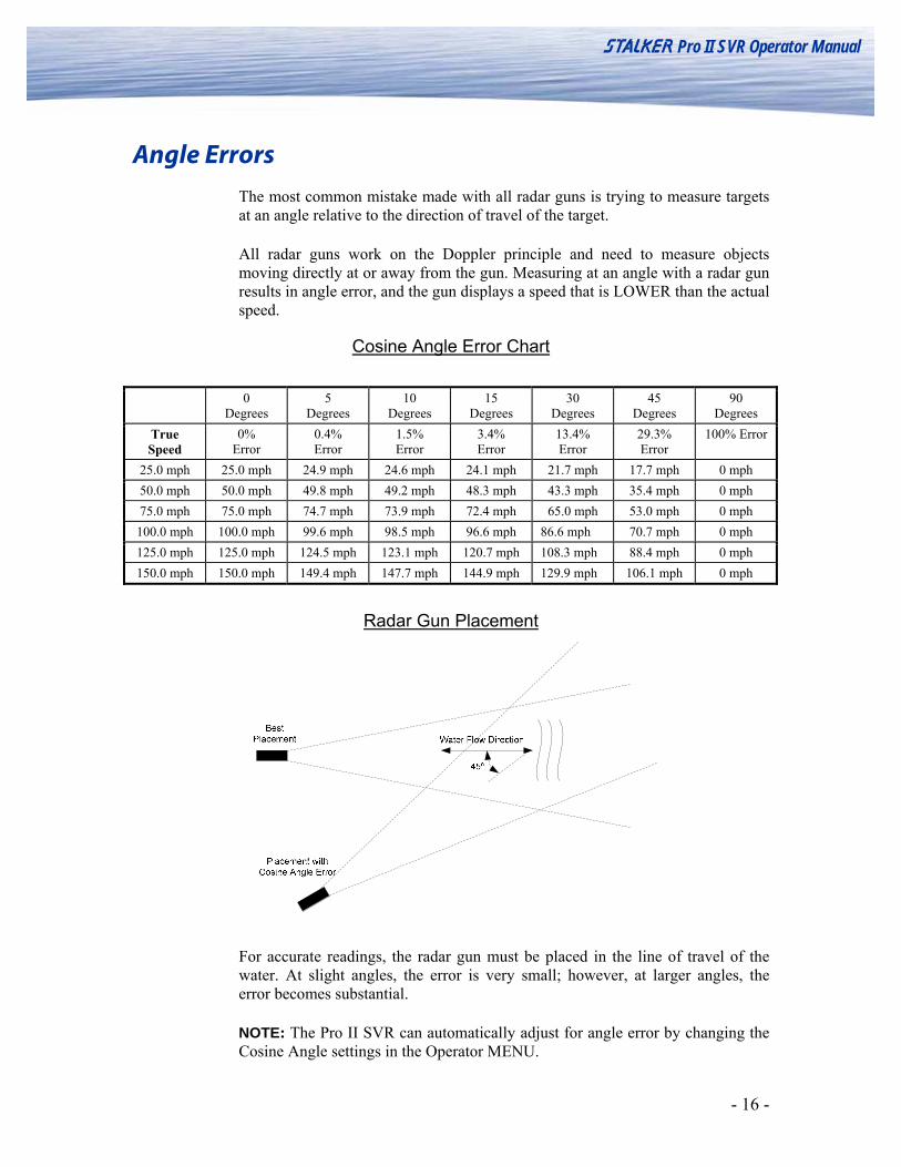
The most common mistake made with all radar guns is trying to measure targets at an angle relative to the direction of travel of the target.
All radar guns work on the Doppler principle and need to measure objects moving directly at or away from the gun. Measuring at an angle with a radar gun results in angle error, and the gun displays a speed that is LOWER than the actual speed.
Cosine Angle Error Chart
0 Degrees
5 Degrees
10 Degrees
15 Degrees
30 Degrees
45 Degrees
90 Degrees
True Speed
0% Error
0.4% Error
1.5% Error
3.4% Error
13.4% Error
29.3% Error
100% Error
25.0 mph 25.0 mph 24.9 mph 24.6 mph 24.1 mph 21.7 mph 17.7 mph 0 mph 50.0 mph 50.0 mph 49.8 mph 49.2 mph 48.3 mph 43.3 mph 35.4 mph 0 mph 75.0 mph 75.0 mph 74.7 mph 73.9 mph 72.4 mph 65.0 mph 53.0 mph 0 mph 100.0 mph 100.0 mph 99.6 mph 98.5 mph 96.6 mph 86.6 mph 70.7 mph 0 mph 125.0 mph 125.0 mph 124.5 mph 123.1 mph 120.7 mph 108.3 mph 88.4 mph 0 mph 150.0 mph 150.0 mph 149.4 mph 147.7 mph 144.9 mph 129.9 mph 106.1 mph 0 mph
Radar Gun Placement
For accurate readings, the radar gun must be placed in the line of travel of the water. At slight angles, the error is very small; however, at larger angles, the error becomes substantial.
NOTE: The Pro II SVR can automatically adjust for angle error by changing the Cosine Angle settings in the Operator MENU.
- 17 -
S Pro II SVR Operator Manual
Calculating Angle Errors If you know the angle at which you are clocking, you can calculate the actual velocity by taking the radar reading and dividing by the cosine of the angle. For example: if you are clocking at 30 degrees, and the gun displays 129.9 mph, take 129.9 and divide by the cosine of 30 degrees (0.866) to get a true speed of 150.0 mph.

- 18 -
S Pro II SVR Operator Manual
Interference Problems
Interference Frequencies
The S Pro II SVR radar transmits at a frequency of 34.7 GHz (34,700,000,000 Hz), using a Ka-Band Transmitter. The receiver is designed to read the Doppler frequency (the change in frequency) between 500 Hz and 15,500 Hz. There are very few devices other than another radar gun that could cause interference in a radar gun’s transmission frequency range. However, there are a number of devices that could interfere with a radar gun in the receiver’s frequency range.
What Does Interference Do?
Interference can cause a radar gun to read random readings, or make it harder for the radar gun to “see” the intended target. A variety of sources, both natural and man-made, can cause misleading indications or poor performance. The operator should note the sources described below, and take steps to avoid the problem, or ignore the misleading indications.
Sources of Interference
Terrain Radar signals will not pass through most solid objects, including tree foliage. Make certain the path between the radar and target is unobstructed.
Rain Rain absorbs and scatters the radar signal. This reduces the range and increases the possibility of obtaining readings from the speed of the raindrops.
Electrical Noise Electrical noise sources include neon signs, radio transmitters, power lines, and transformers. These influences may cause reduced range or intermittent readings.
- 19 -
S Pro II SVR Operator Manual
FCC Requirements
The Federal Communications Commission requires that all transmitting equipment carry a Grant of Type Acceptance. The S Pro II SVR is Type Accepted by the FCC under Type Acceptance number IBQACMI002. The FCC also requires that an operating license be obtained by the user of the equipment.
Why Testing is important
In order to ensure continued compliance with FCC rules, meet legal requirements for admissibility of radar speed measurements, and verify full operating performance, the following test procedures are recommended. If the unit fails any of the tests, it should be removed from service until the cause of the problem is corrected.
Periodic Calibration We recommend that the following performance characteristics should be verified on a regular basis: Transmitter frequency is within specification of licensed operating frequency. Unit indicates correct speed (±0.1 m/s) when reading a target of known speed.
Pro II SVR Accessories The S Pro II SVR radar gun has a host of optional accessories. For current pricing and availability, contact sales at 1-888-STALKER.
Accessories 200-0804-00, Tripod mount kit
155-2272-00, Stopwatch/Radar Control Cable – a 4 foot cable with
momentary switch that connects to the 8 pin interface connector. Can remotely control radar trigger.
155-2232-00, 12VDC CIG Cable – Connects to the 8 pin interface
connector and plugs into a cigarette lighter receptacle.
200-0760-00, Battery Charger kit for charging battery through side data port.
RS-232 Serial Cable that connects to the 8 pin interface connector for
RS-232 data output.
200-0661-01, Spare Battery Handle

- 20 -
S Pro II SVR Operator Manual
Service Information
A Check List Before Servicing the Pro II SVR Radar
Check the Settings - If you are having a problem with your Pro II SVR, first make sure that the settings are correct for your application. Read the Operator and Option Setup MENUS sections. Call Customer Service at 1-877-STALKER if you need help with this. Check the Battery - If the Pro II SVR does not turn on, the problem is usually with the battery handle. Try charging the battery handle. If it still does not turn on, you could use a volt meter to see if the batteries are producing at least 7.2 volts. You may need to order new batteries. Call Customer Service - If the problem is not rectified with these steps, call Customer Service at 1- 877-STALKER for help. A service representative will determine if the gun needs to be sent to the factory.
Factory Service Center Address
Applied Concepts, Inc. Attn. Repair Department 2609 Technology Drive Plano, TX 75074 1-877-STALKER Toll Free Phone: (972) 801-4807 Fax: (972) 398-3781
Warranty Information
The Pro II SVR radar is covered for Two (2) Full Year, Parts and Labor, against defects in workmanship, parts, or materials, and is guaranteed to operate within specifications for that period. S Radar will repair or replace, at their option, any component or system found to be defective. The customer is responsible for shipping the defective product to the factory (freight prepaid), and S Radar will pay for the return shipping via UPS ground service back to the customer. Any expedited air shipping charges are to be paid by the customer. This full warranty does not cover damage due to dropping, water, salt, improper voltage, fire, charging alkaline batteries in the unit, attempted repairs or modifications by an unauthorized service agent, or any other unusual treatment.

- 21 -
S Pro II SVR Operator Manual
S Pro II SVR
Specifications PERFORMANCE SPECIFICATIONS
Speed Range .2 – 18.0 meters per second Accuracy ± 0.1 meters per second In onES resolution, round to the nearest integer; In tnth resolution, round to nearest tenth. Vertical Angle accuracy ±2º Vertical angle resolution 1º
MICROWAVE SPECIFICATIONS
Operating Frequency 34.7 GHz (Ka-Band) ± 50 MHz Polarization Circular Polarization 3 db Beam width 12 Degrees Nominal (± 1°) Microwave Source Gunn-Effect Diode Receive Type Schottky Barrier Mixer Diode Power Output 20 Milliwatts Minimum 25 Milliwatts Nominal 50 Milliwatts Maximum The STALKER Pro II SVR Complies with Part 90 of the FCC rules. FCC ID #IBQACMI002.
GENERAL SPECIFICATIONS
Product Type Stationary Doppler Radar Computer Processor Digital Signal Processor Display Type Liquid Crystal Operating Temperatures -30°C to +70°C (-22°F to +158°F) Storage Temperatures -40°C to +85°C (-40°F to +185°F)
ELECTRICAL SPECIFICATIONS
Battery Capacity 7.2 VDC, 2.4 Ah, Li-Ion Current Requirements Transmitting - 0.73 Amps (At 7.2 Volts DC) Standby - 0.32 Amps
Sleep Mode - 0.085 Amps PHYSICAL SPECIFICATIONS
Weight (with battery handle) 2.15 Pounds Dimensions 7.35” H x 2.83” W x 7.9” L

- 22 -
S Pro II SVR Operator Manual
Housing Material Aluminum and Magnesium
Serial Communications Protocol
Physical Interface An RS-232 or RS-485 Serial Cable is required for data communications to speed display boards, computers, and other electronic devices. The data connector is on the side of the unit. Connector Signals:
1. Ground 2. Voltage Input 3. 7 Volts (out) 4. RS-485 A 5. RS-485 B 6. Aux Input 7. RS-232 RX 8. RS-232 TX
BAUD Rate 1200 to 38400 BAUD – default =9600 BAUD Data Format 8 Data Bits No Parity 1 Stop Bit
Serial Port Message Formats Format A and AP are similar with the difference being that in format A the reported speed is the average current speed; in AP the speed reported is the current speed.
A & AP Format – Resolution = ones Byte# Content 1 Speed hundreds digit (ASCII) 2 Speed tens digit (ASCII) 3 Speed ones digit (ASCII) 4(+) Carriage Return (0x0D) or alternate termination string determined by the
message termination setting A & AP Format – Resolution = tenths Byte# Content 1 Speed hundreds digit (ASCII) 2 Speed tens digit (ASCII) 3 Speed ones digit (ASCII) 4 Decimal Point (0x2E) 5 Speed tenths digit (ASCII) 6(+) Carriage Return (0x0D) or alternate termination string determined by the
message termination setting
- 23 -
S Pro II SVR Operator Manual
The Leading Zero setting affects formats A: When set to SPAC (default setting), ASCII spaces are used for leading zeros: “500” or “500.0” “ 50” or “ 50.0” “ 5” or “ 5.0” When set to 2Ero, ASCII zeros are used for leading zeros: “500” or “500.0” “050” or “050.0” “005” or “005.0”
For Format A, when set to nonE, leading zero characters are not transmitted, and the message length is reduced by the number of skipped zeros.
“500” or “500.0” “50” or “50.0” “5" or “5.0” The Message Termination setting affects both format A and AP: When set to Cr (default setting), each message is terminated with only a carriage return:
(0x0D). When set to CrLF, each message is terminated with a carriage return and a line feed:
(0x0D, 0x0A). When set to u Cr, each message is terminated with the speed’s units and a carriage
return: “500MPH(0x0D)”. When set to u CL, each message is terminated with the speed’s units, a carriage return
and a line feed:”500MPH(0x0D0A)”. .

The STALKER Pro II SVR Radar is Manufactured by Applied Concepts, Inc.
Copyright © 2008 by Applied Concepts, Inc. STALKER RADAR
2609 Technology Drive Plano, TX 75074 1-888-STALKER
(972) 398-3780 Sales (972) 398-3781 Fax
www.stalkerradar.com
Made in U.S.A. *011009800* 011-0098-00 Rev C