surface crack problem for functionally graded magnetoelectroelastic coating–homogeneous elastic...
TRANSCRIPT

Engineering Fracture Mechanics 76 (2009) 269–285
Contents lists available at ScienceDirect
Engineering Fracture Mechanics
journal homepage: www.elsevier .com/locate /engfracmech
Surface crack problem for functionally graded magnetoelectroelasticcoating–homogeneous elastic substrate system under anti-planemechanical and in-plane electric and magnetic loading
Li Ma a,*, Lin-Zhi Wu a, Lin-Ping Feng b
a Center for Composite Materials, Harbin Institute of Technology, Harbin 150080, Chinab Navy Submarine Academy, Qingdao 266071, China
a r t i c l e i n f o
Article history:Received 8 November 2007Received in revised form 23 September2008Accepted 1 October 2008Available online 14 October 2008
Keywords:Magnetoelectroelastic materialCoating–substrate structureCrackField intensity factorEnergy release rate
0013-7944/$ - see front matter � 2008 Elsevier Ltddoi:10.1016/j.engfracmech.2008.10.002
* Corresponding author. Tel.: +86 451 86402739;E-mail address: [email protected] (L. Ma).
a b s t r a c t
A functionally graded magnetoelectroelastic material layer bonded to a homogeneous elas-tic substrate is investigated. The functionally graded magnetoelectroelastic layer contains asurface crack that is perpendicular to the surface of the medium. The structure is subjectedto anti-plane mechanical and in-plane electric and magnetic loads, the crack probleminvolves the anti-plane elastic field coupled with the in-plane electric and magnetic field.The elastic layer can be an ideal insulator or an ideal conductor. Integral transform and dis-location density functions are employed to reduce the problem to the solution of a systemof singular integral equations. Numerical results show the influences of the material gradi-ent parameter and crack configuration on field intensity factors and energy release rates ofthe functionally graded magnetoelectroelastic coating–homogeneous elastic substratestructure.
� 2008 Elsevier Ltd. All rights reserved.
1. Introduction
Composite materials consisting of a piezoelectric phase and a piezomagnetic phase simultaneously process piezoelectric,piezomagnetic and magnetoelectric effects, and thus they have wide applications in microwave electronics, optoelectronicsand electronic instrumentation [1,2]. Due to multi-field coupled effects, a magnetic field may induce an electric field and anelastic field in a magnetoelectroelastic solid, and vise versa. The coupled properties of piezoelectric–piezomagnetic compos-ites offer great opportunities for engineers to create intelligent structures and devices that are capable of responding to inter-nal and/or environment changes. Studies of the properties of piezoelectric–piezomagnetic composites have been carried outby numerous investigators in recent years, e.g., Nan [3], Huang et al. [4], Li [5], Soh et al. [6] and others. When subjected tomechanical, magnetic and electrical loads in service, these magnetoelectroelastic composites can fail prematurely due to de-fects, such as cracks, holes and inclusions, arising during their manufacturing process. Therefore, it is of great importance tostudy the fracture behaviors of piezoelectric–piezomagnetic composites with cracks under the magnetoelectroelastic inter-action. Recently, Song and Sih [7] investigated crack initiation behavior in a magnetoelectroelastic composite under in-planedeformation. Gao et al. [8] presented an exact treatment of crack problems in a magnetoelectroelastic solid subjected to far-field loadings. Wang and Mai [9] obtained the general two-dimensional solutions to the magnetoelectroelastic problem of acrack via the extended Stroh formalism. The same authors [10] also considered mode III crack problems in an infinite mag-netoelectroelastic medium using a complex variable technique.
. All rights reserved.
fax: +86 451 86402386.

Nomenclature
x,y,z Cartesian coordinatesc length of crackh width of functionally graded magnetoelectroelastic striphe width of homogeneous elastic substratew z-component of the displacement vector for functionally graded magnetoelectroelastic strip/ electric potential of functionally graded magnetoelectroelastic stripw magnetic potential of functionally graded magnetoelectroelastic stripskz (k = x,y) anti-plane shear stress of functionally graded magnetoelectroelastic stripDk (k = x,y) electric displacement of functionally graded magnetoelectroelastic stripBk (k = x,y) magnetic induction of functionally graded magnetoelectroelastic stripc44 elastic constant of functionally graded magnetoelectroelastic stripe15 piezoelectric constant of functionally graded magnetoelectroelastic stripf15 piezomagnetic constant of functionally graded magnetoelectroelastic stripe11 dielectric constant of functionally graded magnetoelectroelastic stripg11 electromagnetic constant of functionally graded magnetoelectroelastic stripl11 magnetic constant of functionally graded magnetoelectroelastic stripb parameter to describe the material gradient distributionce
44 elastic constant of the elastic layerwe z-component of the displacement vector for the elastic layerr2 ¼ @2
@x2 þ @2
@y2 the two-dimensional Laplace operator in the variables x and ygw(x), g/(x), gw(x) dislocation density functionKIII stress intensity factor (SIF)KD electric displacement intensity factor (EDIF)KB magnetic induction intensity factor (MIIF)G energy release rate (ERR)
270 L. Ma et al. / Engineering Fracture Mechanics 76 (2009) 269–285
In practical applications, a magnetoelectroelastic layer is usually bonded to an elastic substrate. Due to the difference ofthe thermo-physical properties between the magnetoelectroelastic layer and the substrate, the surface of the magnetoelec-troelastic layer may suffer cracking during processing or under influence of the environment. Therefore, study of the surfacecracking of laminated magnetoelectroelastic medium is of great importance. The problem of an edge crack has been studiedin Refs. [11,12] for homogeneous layers under mechanical load. The problem of an edge or an embedded crack perpendicularto the surface of the magnetoelectroelastic layer has been considered for coupled magnetoelectromechanical load [13,14].The dynamic fracture of an embedded crack in magnetoelectroelastic strip has been considered by Yong and Zhou [15]. Inthese papers, only homogeneous magnetoelectroelastic layers were investigated.
On the other hand, the development of functionally graded materials (FGMs) has demonstrated that they have the poten-tial to reduce the stress concentration and increase the fracture toughness. Consequently, the concept of FGMs can be ex-tended to the magnetoelectroelastic materials to improve the reliability of magnetoelectroelastic materials andstructures. These new kinds of materials with continuously varying properties may be called functionally graded magneto-electroelastic materials. The advantages of using a device wholly made of the functionally graded magnetoelectroelasticmaterials or using the functionally graded magnetoelectroelastic materials as a transit layer instead of the bonding agentare that no discernible internal seams or boundaries exist. So the failure from internal de-bonding or stress peaks developedin conventional bimorphs can be avoided. Because the functionally graded magnetoelectroelastic materials are just emergingclass of magnetoelectroelastic materials, researches on the fracture mechanical behaviors of this kind of materials are stillvery few. The problem of an edge or an embedded crack perpendicular to the surface of the functionally graded magneto-electroelastic layer has been considered by Ma et al. [16] for coupled magnetoelectromechanical load. The dynamic fractureof an edge crack in functionally graded magnetoelectroelastic strip has been considered by Feng and Su [17,18].
For many practical devices, functionally graded magnetoelectroelastic structures are surface-mounted. An important frac-ture mode is that the functionally graded magnetoelectroelastic layer contains a crack perpendicular to its surface. To theauthors’ knowledge, such problems have not yet been reported in the literature. This is the motivation of present work.
In this paper, the anti-plane problem of a functionally graded magnetoelectroelastic material layer bonded to a homoge-neous elastic substrate is investigated. The functionally graded magnetoelectroelastic layer contains a surface crack that isperpendicular to the surface of the medium. The crack is assumed to be impermeable or permeable for magnetic and electricfields, and the elastic layer can be an ideal insulator or an ideal conductor. Integral transform and dislocation density func-tions are employed to reduce the problem to the solution of a system of singular integral equations. The resulting singularintegral equation is then approximated as a system of linear algebraic equations, which are finally solved. Field intensity fac-tors and energy release rates (ERRs) in the physical domain are obtained and analyzed. Numerical results show the influ-ences of the material gradient parameter and crack configuration on field intensity factors and energy release rates of the

L. Ma et al. / Engineering Fracture Mechanics 76 (2009) 269–285 271
functionally graded magnetoelectroelastic coating–homogeneous elastic substrate structure. Results presented in this papershould have potential applications to the design of magnetoelectroelastic coating/elastic substrate structures.
2. Formulation of the problem
The problem under consideration is described in Fig. 1. A functionally graded magnetoelectroelastic strip of width h con-tain a crack of length c (0 < c < h) perpendicular to the interface bonded to a homogeneous elastic substrate of width he. Thesystem of rectangular Cartesian coordinates (x,y,z) is introduced in the layered material in such a way that the crack is lo-cated along the x-axis, and the y-axis is parallel to the interface. In the following, the subscripts, x, y, z, will be used to refer tothe direction of coordinates, respectively. The functionally graded magnetoelectroelastic layer exhibits transversely isotropicbehavior and is poled in z-direction.
When the structure is subjected to anti-plane mechanical and in-plane electric and magnetic loads, the crack probleminvolves the anti-plane elastic field coupled with the in-plane electric and magnetic field. The constitutive equations forthe functionally graded magnetoelectroelastic materials are as follows:
skz ¼ c44@w@kþ e15
@/@kþ f15
@w@k
ð1aÞ
Dk ¼ e15@w@k� e11
@/@k� g11
@w@k
ð1bÞ
Bk ¼ f15@w@k� g11
@/@k� l11
@w@k
ð1cÞ
where skz, Dk, Bk (k = x,y) are the anti-plane shear stress, in-plane electric displacement and magnetic induction, respectively;c44, e15, f15, e11, g11 and l11 are the elastic, the piezoelectric, the piezomagnetic, dielectric, electromagnetic and the magneticconstants, respectively; w, / and w are the mechanical displacement, electric potential and magnetic potential of the func-tionally graded magnetoelectroelastic strip, respectively.
The material properties are assumed to be one-dimensionally dependent as
c44 ¼ c440ebx; e11 ¼ e110ebx; e15 ¼ e150ebx; f 15 ¼ f150ebx; g11 ¼ g110ebx; l11 ¼ l110ebx ð2Þ
where c440, e110, e150, f150, g110 and l110 are the material constants at x = 0; b is a parameter to describe the material gradientdistribution.
Substituting Eqs. (1) into the basic equations of magnetoelectroelastic boundary value problem, i.e.,
@sxz
@xþ @syz
@y¼ 0 ð3aÞ
@Dx
@xþ @Dy
@y¼ 0 ð3bÞ
@Bx
@xþ @By
@y¼ 0 ð3cÞ
We can obtained the equilibrium equation for functionally graded magnetoelectroelastic materials as follows:
x
y
ch
eh
Functionally graded Magnetoelectroelastic strip
Elastic strip
o
Fig. 1. Geometry of the crack problem in the functionally graded coating–homogeneous substrate structure.

272 L. Ma et al. / Engineering Fracture Mechanics 76 (2009) 269–285
c440 r2wþ b@w@x
� �þ e150 r2/þ b
@/@x
� �þ f150 r2wþ b
@w@x
� �¼ 0 ð4aÞ
e150 r2wþ b@w@x
� �� e110 r2/þ b
@/@x
� �� g110 r2wþ b
@w@x
� �¼ 0 ð4bÞ
f150 r2wþ b@w@x
� �� g110 r2/þ b
@/@x
� �� l110 r2wþ b
@w@x
� �¼ 0 ð4cÞ
where r2 ¼ @2
@x2 þ @2
@y2 is the two-dimensional Laplace operator in the variables x and y.For convenience of mathematics and similar to the method mentioned by Feng and Su [17], we assume
/ ¼ d1wþ e1vþ f1f; w ¼ d2wþ e2vþ f2f ð5Þ
whered1 ¼e150l110 � f150g110
l110e110 � g2110
; e1 ¼�l110
l110e110 � g2110
; f 1 ¼g110
l110e110 � g2110
ð6aÞ
d2 ¼e110f150 � e150g110
l110e110 � g2110
; e2 ¼g110
l110e110 � g2110
; f 2 ¼�e110
l110e110 � g2110
ð6bÞ
are the known constants. The governing Eqs. (4) can be expressed as
r2wþ b@w@x¼ 0 ð7aÞ
r2vþ b@v@x¼ 0 ð7bÞ
r2fþ b@f@x¼ 0 ð7cÞ
The constitutive relations Eqs. (1) can be rewritten as
sxz ¼ ebx m10@w@xþm20
@v@xþm30
@f@x
� �; syz ¼ ebx m10
@w@yþm20
@v@yþm30
@f@y
� �ð8aÞ
Dx ¼ ebx @v@x
; Dy ¼ ebx @v@y
ð8bÞ
Bx ¼ ebx @f@x; By ¼ ebx @f
@yð8cÞ
where
m10 ¼ c440 þe110f 2
150 � 2e150f150g110 þ l110e2150
l110e110 � g2110
ð9aÞ
m20 ¼f150g110 � e150l110
l110e110 � g2110
ð9bÞ
m30 ¼e150g110 � f150e110
l110e110 � g2110
ð9cÞ
The constitutive equations of the elastic layer are
sexz ¼ ce
44@we
@x; se
yz ¼ ce44@we
@yð10Þ
where the subscript e represents the elastic layer, ce44 is elastic constant of the elastic layer and have ce
44 ¼ c440ebh, we is thez-component of the displacement vector for the elastic layer. The equilibrium equation for the elastic layer is as follows:
@2we
@x2 þ@2we
@y2 ¼ 0 ð11Þ
3. Solution of the functionally graded magnetoelectroelastic strip
Employing the Fourier Sine transform on the variable x and the Fourier transform on the variable y and considering atinfinity the quantity in the left side of Eqs. (4) must bounded, it can be shown that
wðx; yÞ ¼ 12p
Z 1
�1A1ðsÞe�m1ye�isxdsþ 2
p
Z 1
0A2ðsÞem2x þ A3ðsÞem3x½ � sinðsyÞds ð12aÞ
vðx; yÞ ¼ 12p
Z 1
�1B1ðsÞe�m1ye�isxdsþ 2
p
Z 1
0B2ðsÞem2x þ B3ðsÞem3x½ � sinðsyÞds ð12bÞ
fðx; yÞ ¼ 12p
Z 1
�1C1ðsÞe�m1ye�isxdsþ 2
p
Z 1
0C2ðsÞem2x þ C3ðsÞem3x½ � sinðsyÞds ð12cÞ

L. Ma et al. / Engineering Fracture Mechanics 76 (2009) 269–285 273
where Aj(s), Bj(s), Cj(s), (j = 1,2,3) are unknown functions to be determined and
m1ðsÞ ¼ffiffiffiffiffiffiffiffiffiffiffiffiffiffiffiffiffiffisðsþ ibÞ
qð13aÞ
m2ðsÞ ¼ �b=2�ffiffiffiffiffiffiffiffiffiffiffiffiffiffiffiffiffiffiffiffib2=4þ s2
qð13bÞ
m3ðsÞ ¼ �b=2þffiffiffiffiffiffiffiffiffiffiffiffiffiffiffiffiffiffiffiffib2=4þ s2
qð13cÞ
The corresponding stress, electric displacements and magnetic induction are given as
sxzðx; yÞ ¼ ebx � 12p
Z 1
�1is m10A1ðsÞ þm20B1ðsÞ þm30C1ðsÞ½ �e�m1ðsÞye�isxds
�þ 2
p
Z 1
0
X3
i¼2
miðsÞ m10AiðsÞ þm20BiðsÞ þm30CiðsÞ½ �emiðsÞx sinðsyÞds
)ð14aÞ
syzðx; yÞ ¼ ebx � 12p
Z 1
�1m1ðsÞ m10A1ðsÞ þm20B1ðsÞ þm30C1ðsÞ½ �e�m1ðsÞye�isxds
�þ 2
p
Z 1
0sX3
i¼2
m10AiðsÞ þm20BiðsÞ þm30CiðsÞ½ �emiðsÞx cosðsyÞds
)ð14bÞ
Dxðx; yÞ ¼ ebx � 12p
Z 1
�1isB1ðsÞe�m1ðsÞye�isxdsþ 2
p
Z 1
0
X3
i¼2
miðsÞBiðsÞemiðsÞx sinðsyÞds
( )ð15aÞ
Dyðx; yÞ ¼ ebx � 12p
Z 1
�1m1ðsÞB1ðsÞe�m1ðsÞye�isxdsþ 2
p
Z 1
0sX3
i¼2
BiðsÞemiðsÞx cosðsyÞds
( )ð15bÞ
Bxðx; yÞ ¼ ebx � 12p
Z 1
�1isC1ðsÞe�m1ðsÞye�isxdsþ 2
p
Z 1
0
X3
i¼2
miðsÞCiðsÞemiðsÞx sinðsyÞds
( )ð16aÞ
Byðx; yÞ ¼ ebx � 12p
Z 1
�1m1ðsÞC1ðsÞe�m1ðsÞye�isxdsþ 2
p
Z 1
0sX3
i¼2
CiðsÞemiðsÞx cosðsyÞds
( )ð16bÞ
4. Solution of the elastic substrate
The solution of the governing Eq. (11) for the elastic layer can be expressed in the following form:
weðx; yÞ ¼ 2p
Z 1
0D1ðsÞesx þ D2ðsÞe�sx½ � sinðsyÞds ð17Þ
From the constitutive Eq. (10) and the displacement expression (17), the stress for the elastic layer can be obtained asfollows:
sexzðx; yÞ ¼ ce
442p
Z 1
0s D1ðsÞesx � D2ðsÞe�sx½ � sinðsyÞds ð18aÞ
seyzðx; yÞ ¼ ce
442p
Z 1
0s D1ðsÞesx þ D2ðsÞe�sx½ � cosðsyÞds ð18bÞ
5. Boundary and interface conditions
At the functionally graded magnetoelectroelastic strip, the mixed boundary value problem shown in Fig. 1 must be solvedunder the following conditions. For the magnetoelectrically impermeable crack, the boundary conditions are
sxzð0; yÞ ¼ Dxð0; yÞ ¼ Bxð0; yÞ ¼ 0; �1 < y <1 ð19aÞsyzðx; 0Þ ¼ �s0; Dyðx; 0Þ ¼ �D0; Byðx;0Þ ¼ �B0; a < x < b ð19bÞwðx; 0Þ ¼ /ðx;0Þ ¼ wðx;0Þ ¼ 0; 0 6 x 6 a; b 6 x 6 h ð19cÞ
For the magnetoelectrically permeable crack, the boundary conditions are
sxzð0; yÞ ¼ Dxð0; yÞ ¼ Bxð0; yÞ ¼ 0; �1 < y <1 ð20aÞsyzðx; 0Þ ¼ �s0; a < x < b ð20bÞwðx; 0Þ ¼ 0; 0 6 x 6 a; b 6 x 6 h ð20cÞ/ðx; 0Þ ¼ wðx;0Þ ¼ 0; 0 6 x 6 h ð20dÞ

274 L. Ma et al. / Engineering Fracture Mechanics 76 (2009) 269–285
The electric displacement Dy(x,0) and magnetic induction By (x,0) on the crack surfaces consist of two components. Thefirst is the imposed electric displacement �D0 and magnetic induction �B0 for Dy(x,0) and By(x,0). The second is the un-known caused by �s0 for both of Dy(x,0) and By(x,0) [17].
At the interface x = h, we have the stresses and displacements continuity conditions
sxzðh; yÞ ¼ sexzðh; yÞ; �1 < y <1 ð21Þ
wðh; yÞ ¼ weðh; yÞ; �1 < y <1 ð22Þ
The bottom surface of the elastic layer is considered to be shear stress-free such that
sexzðhþ he; yÞ ¼ 0; �1 < y <1 ð23Þ
For the shear stress on the bottom surface of the elastic layer, and the electric and magnetic state on the bottom surface ofthe magnetoelectroelastic layer, we investigate two cases
Case I: The elastic layer is electrically and magnetically insulated on its bottom surface
Dxðh; yÞ ¼ Bxðh; yÞ ¼ 0; �1 < y <1 ð24aÞ
Case II: The elastic layer is electrically and magnetically grounded on its bottom surface
Exðh; yÞ ¼ Hxðh; yÞ ¼ 0; �1 < y <1 ð24bÞ
Note that a grounded state for a medium means that the medium is in an equaling electric potential state (usually be zeroelectric potential), and the electric field inside the medium is zero. On the other hand, and insulated state means that theelectric displacement in the medium is zero.
To make the solution satisfy the boundary conditions (19)–(24), we introduce the following dislocation density functions
gwðxÞ ¼@wðx;0Þ@x ; x 6 c
0; x > c
(ð25aÞ
g/ðxÞ ¼@/ðx;0Þ@x ; x 6 c
0; x > c
(ð25bÞ
gwðxÞ ¼@wðx;0Þ@x ; x 6 c
0; x > c
(ð25cÞ
Substituting Eqs. (5) and (12) into Eqs. (25) and applying the Fourier inverse transform, the unknown functions A1(s), B1(s)and C1(s) can be obtained that
A1ðsÞ ¼is
Z c
0gwðtÞeistdt ð26aÞ
B1ðsÞ ¼is
Z c
0geeg
w/wðtÞeistdt ð26bÞ
C1ðsÞ ¼is
Z c
0gfgl
w/wðtÞeistdt ð26cÞ
Z c
0gwðtÞdt ¼ 0;
Z c
0g/ðtÞdt ¼ 0;
Z c
0gwðtÞdt ¼ 0 ð27Þ
where
geegw/wðtÞ ¼ e150gwðtÞ � e110g/ðtÞ � g110gwðtÞ ð28aÞ
gfglw/wðtÞ ¼ f150gwðtÞ � g110g/ðtÞ � l110gwðtÞ ð28bÞ
Using Eqs. (8), (12), (26), together with the boundary conditions (19), and interfacial continuity conditions (21) and (22),and by inverting the corresponding Fourier integral, we obtain
A2ðsÞm2ðsÞ þ A3ðsÞm3ðsÞ ¼Z c
0gwðtÞF1ðs; tÞdt ð29aÞ
B2ðsÞm2ðsÞ þ B3ðsÞm3ðsÞ ¼Z c
0geeg
w/wðtÞF1ðs; tÞdt ð29bÞ
C2ðsÞm2ðsÞ þ C3ðsÞm3ðsÞ ¼Z c
0gfgl
w/wðtÞF1ðs; tÞdt ð29cÞ

L. Ma et al. / Engineering Fracture Mechanics 76 (2009) 269–285 275
m10A2 þm20B2 þm30C2ð Þm2em2h þ m10A3 þm20B3 þm30C3ð Þm3em3h
� ce44s D1esh � D2e�sh� �
¼Z c
0c440gwðtÞ þ e150g/ðtÞ þ f150gwðtÞ� �
F2ðs; tÞdt ð29dÞ
A2ðsÞem2h þ A3ðsÞem3h � D1esh � D2e�sh ¼Z c
0gwðtÞF3ðs; tÞdt ð29eÞ
From boundary condition (23), we obtain
D1ðsÞesðhþheÞ � D2ðsÞe�sðhþheÞ ¼ 0 ð30Þ
As far as the boundary conditions (24) for the elastic layer, we have the following cases:Case I: If the elastic layer is electrically and magnetically insulated at its bottom surface, then
B2ðsÞm2ðsÞem2h þ B3ðsÞm3ðsÞem3h ¼Z c
0geeg
w/wðtÞF2ðs; tÞdt ð31aÞ
C2ðsÞm2ðsÞem2h þ C3ðsÞm3ðsÞem3h ¼Z c
0gfgl
w/wðtÞF2ðs; tÞdt ð31bÞ
Case II: If the elastic layer is electrically and magnetically grounded at its bottom surface, then
Z cðd1A2 þ e1B2 þ f1C2Þm2em2h þ d1A3 þ e1B3 þ f1C3ð Þm3em3h ¼0
g/ðtÞF2ðs; tÞdt ð32aÞ
ðd2A2 þ e2B2 þ f2C2Þm2em2h þ d2A3 þ e2B3 þ f2C3ð Þm3em3h ¼Z c
0gwðtÞF2ðs; tÞdt ð32bÞ
where the expressions of functions Fj(s, t) (j = 1,2) are
F1ðs; tÞ ¼1
2p
Z 1
�1
�sm2
1ðqÞ þ s2eiqtdq ð33aÞ
F2ðs; tÞ ¼1
2p
Z 1
�1
�sm2
1ðqÞ þ s2eiqðt�hÞdq ð33bÞ
F3ðs; tÞ ¼1
2p
Z 1
�1
iq
�sm2
1ðqÞ þ s2eiqðt�hÞdq ð33cÞ
By using the theory of residues, the integrals in Eqs. (33) may be evaluated as follows:
F1ðs; tÞ ¼s
m2ðsÞ �m3ðsÞe�tm3ðsÞ ð34aÞ
F2ðs; tÞ ¼s
m2ðsÞ �m3ðsÞeðh�tÞm2ðsÞ ð34bÞ
F3ðs; tÞ ¼m3ðsÞ
m3ðsÞ �m2ðsÞ½ �s eðh�tÞm2ðsÞ ð34cÞ
From Eqs. (34), unknowns A2(s), A3(s), B2(s), B3 (s), C2(s), C3(s), D1(s) and D2(s) can be obtained and given in Appendix A.Substituting these expressions into Eqs. (8), we obtain
syzðx; 0Þ ¼ ebx 12p
Z 1
�1� m10A1ðsÞ þm20B1ðsÞ þm30C1ðsÞ½ �m1ðsÞe�isxds
�þ 2
p
Z 1
0
X3
j¼2
m10AjðsÞ þm20BjðsÞ þm30CjðsÞ� �
emjðsÞxsds
)ð35aÞ
Dyðx; 0Þ ¼ ebx 12p
Z 1
�1�m1ðsÞB1ðsÞe�isxdsþ 2
p
Z 1
0
X3
j¼2
BjðsÞemjðsÞxsds
( )ð35bÞ
Byðx; 0Þ ¼ ebx 12p
Z 1
�1�m1ðsÞC1ðsÞe�isxdsþ 2
p
Z 1
0
X3
j¼2
CjðsÞemjðsÞxsds
( )ð35cÞ
By using the expressions of A1(s), A2(s), A3(s), B1 (s), B2(s), B3(s), C1(s), C2(s), C3(s), D1(s) and D2(s) and the boundary con-dition (19b), we obtain the following integral equations:
Z c
0Hðx; tÞ½ �
gwðtÞg/ðtÞgwðtÞ
8><>:9>=>;dt þ 2
p
Z c
0Gðx; tÞ½ �
gwðtÞg/ðtÞgwðtÞ
8><>:9>=>;dt ¼ e�bx
syðxÞDyðxÞByðxÞ
8><>:9>=>; ð36Þ

276 L. Ma et al. / Engineering Fracture Mechanics 76 (2009) 269–285
where the kernels H(x,t), G(x,t) are given by
Hðx; tÞ½ � ¼ 12pi
Z 1
�1H0½ �eisðt�xÞds ð37Þ
Gðx; tÞ½ � ¼Z 1
0G0½ �sds ð38Þ
The expressions of [H0] and [G0] are given in Appendix B, where [H0] is a constant matrix which depended only on thematerial properties. It can be shown from Eq. (37) that
H½ � ¼ 1p
H0½ �1
t � xð39Þ
By applying Eq. (36) to crack surface boundary conditions (19b), and using (39), we obtain the following singular integralequation:
1p
H0½ �Z c
0
1t � x
gwðtÞg/ðtÞgwðtÞ
8><>:9>=>;dt þ 2
p
Z c
0Gðx; tÞ½ �
gwðtÞg/ðtÞgwðtÞ
8><>:9>=>;dt ¼ e�bx
�s0
�D0
�B0
8><>:9>=>; ð40Þ
6. Solution of integral equation
This integral equation can be used to determine the as yet unknown functions gw, g/, and gw. In order to simplify the anal-ysis, the interval [0,c] is normalized by defining
x ¼ 12
1þ rð Þ; t ¼ 12
1þ uð Þ; 0 < ðt; xÞ < c; �1 < ðr;uÞ < 1 ð41aÞ
gwðtÞ ¼ GwðuÞ; g/ðtÞ ¼ G/ðuÞ; gwðtÞ ¼ GwðuÞ; 0 < ðt; xÞ < c; �1 < ðr; uÞ < 1 ð41bÞ� s0e�bx ¼ fwðrÞ; �D0e�bx ¼ f/ðrÞ; �B0e�bx ¼ fwðrÞ; 0 < ðt; xÞ < c; �1 < ðr;uÞ < 1 ð41cÞ
and then the integral Eq. (40) would become
1p
H0½ �Z 1
�1
1u� r
GwðuÞG/ðuÞGwðuÞ
8><>:9>=>;dt þ 2
p
Z 1
�1G0ðr;uÞ� � GwðuÞ
G/ðuÞGwðuÞ
8><>:9>=>;dt ¼
fwðrÞf/ðrÞfwðrÞ
8><>:9>=>; ð42Þ
where
G0ðr;uÞ ¼ c2
Gðx; tÞ ð43Þ
It can be observed that the weight function of the solution of (42) is w(u) = (1 � u)�1/2, and hence the solution of the inte-gral Eq. (42) may be expressed as [19–21]
GwðuÞ ¼1ffiffiffiffiffiffiffiffiffiffiffiffi
1� up
X1n¼0
cnTnðuÞ � 1 < u < 1 ð44aÞ
G/ðuÞ ¼1ffiffiffiffiffiffiffiffiffiffiffiffi
1� up
X1n¼0
dnTnðuÞ � 1 < u < 1 ð44bÞ
GwðuÞ ¼1ffiffiffiffiffiffiffiffiffiffiffiffi
1� up
X1n¼0
enTnðuÞ � 1 < u < 1 ð44cÞ
where Tn is the Chebyshev polynomial of the first kind and c0,c1,c2 , . . ., d0,d1,d2, . . . and e0,e1,e2, . . . are unknown constants.Note that the single-values condition (27) becomes
Z 1�1GwðtÞdt ¼ 0;
Z 1
�1G/ðtÞdt ¼ 0;
Z 1
�1GwðtÞdt ¼ 0 ð45Þ
From Eqs. (44) and (45) and the orthogonality of Chebyshev polynomials it can be shown that c0 = 0, d0 = 0, e0 = 0. Theremaining constants are then determined by substituting from (44) into (42).
The singularity of the integral Eq. (42) may be removed by using the following relations:
Z 1�1
TnðuÞdu
ðu� rÞffiffiffiffiffiffiffiffiffiffiffiffi1� up ¼ TnðrÞ
Z 1
�1
du
ðu� rÞffiffiffiffiffiffiffiffiffiffiffiffi1� up þ
Z 1
�1
TnðuÞ � TnðrÞðu� rÞ
ffiffiffiffiffiffiffiffiffiffiffiffi1� up du ð46Þ
where in the second term on the right-hand side in the integrand is bounded, the first integral is given by
Z 1�1
du
ðu� rÞffiffiffiffiffiffiffiffiffiffiffiffi1� up ¼ log jBðrÞjffiffiffiffiffiffiffiffiffiffiffiffi
1� rp ðr < 1Þ; BðrÞ ¼ 1þ
ffiffiffiffiffiffiffiffiffiffiffiffiffiffiffiffiffiffiffiffiffið1� rÞ=2
p1�
ffiffiffiffiffiffiffiffiffiffiffiffiffiffiffiffiffiffiffiffiffið1� rÞ=2
p ð47Þ

L. Ma et al. / Engineering Fracture Mechanics 76 (2009) 269–285 277
In the problem under consideration from Eqs. (42), (46) and (47), it may be seen that r = r, which, with �1 < r < 1, indeedsatisfies the condition r < 1. All other integrals involving the solution are evaluated by using Gaussian quadrature, andthe resulting functional equation is solved by using the collocation method [22]. Since it is not possible to investigate theregularity of the corresponding infinite matrix, the convergence of the solution may be examined by varying the numberof the term retained in the series. Because of the nature of the solution in this problem, it is preferable to concentrate thecollocation point uk near the ends. They are, thus, chosen as
TNðulÞ ¼ 0; ul ¼ cos ð2l� 1Þ p2N
n oðl ¼ 1;2; . . . ;NÞ ð48Þ
where N is the number of terms retained in the series.
7. Field intensity factors and energy release rates
After determining the coefficients c1,c2, . . .,cN, d1,d2, . . .,dN and e1,e2, . . .,eN for the edge crack problem, the stress intensityfactors (SIFs), the electric displacement intensity factors (EDIFs) and the magnetic induction intensity factors (MIIFs) at thecrack tips may be defined and evaluated as
KIIIðcÞ ¼ limx!c
ffiffiffiffiffiffiffiffiffiffiffiffiffiffiffiffiffi2ðx� cÞ
psyzðx;0Þ ¼ �e�bc
ffiffifficp X1
n¼1
c44cn þ e15dn þ f15en½ � ð49Þ
KDðcÞ ¼ limx!c
ffiffiffiffiffiffiffiffiffiffiffiffiffiffiffiffiffi2ðx� cÞ
pDyðx; 0Þ ¼ �e�bc
ffiffifficp X1
n¼1
e15cn � e11dn � g15en½ � ð50Þ
KBðcÞ ¼ limx!c
ffiffiffiffiffiffiffiffiffiffiffiffiffiffiffiffiffi2ðx� cÞ
pByðx;0Þ ¼ �e�bc
ffiffifficp X1
n¼1
f15cn � g11dn � l11en� �
ð51Þ
From Eqs. (42), (49)–(51), it is easy to know that the SIFs, the EDIFs and the MIIFs are independent and that they can be ob-tained by solving Eq. (42), respectively. Namely, the SIFs, the EDIFs and the MIIFs are only related to the correspondingmechanical, electrical and magnetic loading. So that it should be noted that for the magnetoelectroelastically impermeablecracks, as electric and/or magnetic load are applied, the SIFs cannot perfectly describe the fracture characteristics as in thepurely elastic case. Therefore, the energy release rates (ERRs) G are introduced by calculating the work done in closing thecrack tip over an infinitesimal distance. In accordance with the definition of the energy release rate proposed by Pak [23],after a similar deriving process carried out by Wang and Yu [24] and Feng and Su [17,18], we can finally obtain
GðcÞ ¼ 12
KIIIðcÞeK wðcÞ þ KDðcÞeK /ðcÞ þ KBðcÞeK wðcÞh i
ð52Þ
where
eK wðcÞ ¼l11e11 � g2
11
� KIIIðcÞ þ e15l11 � f15g11
� KDðcÞ þ f15e11 � e15g11ð ÞKBðcÞ
c44l11e11 þ e215l11 þ f 2
15e11 � c44g211 � 2e15f15g11
� ebc
ð53aÞ
eK /ðcÞ ¼e15l11 � f15g11
� KIIIðcÞ � c44l11 þ f 2
15
� KDðcÞ þ c44g11 þ e15f15ð ÞKBðcÞ
c44l11e11 þ e215l11 þ f 2
15e11 � c44g211 � 2e15f15g11
� ebc
ð53bÞ
eK wðcÞ ¼f15e11 � e15g11ð ÞKIIIðcÞ þ c44g11 þ e15f15ð ÞKDðcÞ � c44e11 þ e2
15
� KBðcÞ
c44l11e11 þ e215l11 þ f 2
15e11 � c44g211 � 2e15f15g11
� ebc
ð53cÞ
For magnetoelectrically permeable case, the field intensity factors and ERRs are, respectively,
KIIIðcÞ ¼ limx!c
ffiffiffiffiffiffiffiffiffiffiffiffiffiffiffiffiffi2ðx� cÞ
psyzðx;0Þ ¼ �e�bc
ffiffifficp X1
n¼1
c44cn ð54Þ
KDðcÞ ¼e15
c44KIIIðcÞ ð55Þ
KBðcÞ ¼f15
c44KIIIðcÞ ð56Þ
GðcÞ ¼ K2IIIðcÞ
2c44ð57Þ
8. Numerical results and discussion
In this section, we carry out numerical calculations for a BaTiO3–CoFe2O4 strip bonded to an elastic graphite/epoxy com-posite material layers, as show in Fig. 1. Consider a BaTiO3–CoFe2O4 Composite, where the matrix is the CoFe2O4 and thereinforced phase is the BaTiO3. Material constants of each phase can be found in the work of Li and Dunn [25]. Obviously,

278 L. Ma et al. / Engineering Fracture Mechanics 76 (2009) 269–285
the effective properties of the composite depend on the volume fraction of its constituents. Many investigators, e.g., Huanget al. [4], Li [5], Li and Dunn [25], Wu and Huang [26], Aboudi [27], Chen et al. [28] and others, have investigated the effectiveproperties of magnetoelectroelastic composites based on different approaches. Recently, Sih and Song [29] presented someeffective properties of the BaTiO3-CoFe2O4 composite for different volume fraction of BaTiO3. In the following numerical cal-culation, the used effective elastic and piezoelectric/magnetic properties for a model magnetoelectricelastic composite areselected as [17]:
Fig. 2.magnet
Fig. 3.magnet
c440 ¼ 44:65� 109N=m2; e150 ¼ 5:7C=m2; e110 ¼ 6:46� 10�9C=Vm; f150 ¼ 275:0N=Am;
l110 ¼ �292:5� 10�6Ns2=C2; g110 ¼ 0:
Note that the volume fraction of the inclusions is taken as Vf = 0.5. The material property for the graphite/epoxy compos-ite material layer is ce
44 ¼ 3:8� 109N=m2. So that the gradient parameter bh should be bh = ln(3.8/44.65) = �2.4638.Numerical results are presented in Figs. 2–7, where the SIFs are normalized by K0 which is determined as K0 ¼ s0
ffiffifficp
andthe ERRs are normalized by G0 which is determined as G0 ¼
s20c
c440þe2150=e110
. The loading combination parameter kD ¼ D0e150s0e110
which
is used to represent the combination between the mechanical load �s0 and electrical load �D0, kB ¼ B0 f150s0l110
which is used torepresent the combination between the mechanical load �s0 and magnetic load �B0.
0.1 0.2 0.3 0.4 0.5 0.60.6
0.8
1.0
1.2
1.4
1.6
Nor
mal
ized
ER
Rs
Relative crack length c/h
Single FGMEE layer, i.e. he=0
FGMEE coating/substrate with h e=h
Solid line: Permeable crackDash line: Impermeable crack
Normalized energy release rate caused by mechanical load s0 relate to normalized crack length c/h for a single functionally gradedoelectroelastic layer and functionally graded magnetoelectroelastic coating–elastic substrate structure (bh = �2.4638).
0.1 0.2 0.3 0.4 0.5 0.60.70
0.75
0.80
0.85
0.90
0.95
1.00
1.05
Nor
mal
ized
SIF
s
Relative crack length c/h
he=0
he=h
he=5h
he=10h
Normalized stress intensity factors caused by mechanical load s0 relate to normalized crack length c/h for a single functionally gradedoelectroelastic layer and functionally graded magnetoelectroelastic coating–elastic substrate structure (bh = �2.4638).

L. Ma et al. / Engineering Fracture Mechanics 76 (2009) 269–285 279
Suppose the medium undergoes a uniform anti-plane shear stress load on crack surface and the electric displacement andthe magnetic induction are zero. Fig. 2 plots the variation of normalized energy release rate G(c)/G0 with crack length cal-culated for values of he = 0 and he = h under condition of case I. As expected, the ERRs increase with increasing crack length.Compare of the normalized ERRs between the magnetoelectrically impermeable and permeable case for surface crack prob-lem in the absence of magnetoelectrical loading (kB = kD = 0) is also given in Fig. 2. From this figure, it can be seen that thevalues of ERRs corresponding to magnetoelectrically impermeable cracks are smaller than corresponding to permeablecracks. There are no other distinct differences. Since both magnetic and electrical loading have no contribution to the EERsfor the magnetoelectrically permeable cracks, the following part of this section will mainly concentrate on the impermeablecase.
Fig. 3 shows the influences of the thickness of elastic substrate he/h on the normalized stress intensity factors under con-dition of case I. It can be seen that with the increasing of he/h, the normalized SIFs will decrease for the same crack length.However, with the increasing of crack length c/h, the normalized SIFs will decrease. The influences of the thickness ratio he/hon the normalized SIFs are negligible when he/h > 1 can also be found in this figure.
Fig. 4 shows the effects of the loading combination parameter kD on the normalized energy release rate G(c)/G0 whenkB = 0.5 and he = h under condition of case I. It can be seen that with the increasing of kD, the normalized ERRs will decreasefor the same crack length.
0.1 0.2 0.3 0.4 0.5 0.610
20
30
40
50
60
70
Nor
mal
ized
ER
Rs
Relative crack length c/h
λB=0.5, λD=0.0
λB=0.5, λD=1.0
λB=0.5, λD=2.0
Fig. 4. Normalized energy release rate caused by magnetoelectromechanical combinational load relate to normalized crack length c/h for functionallygraded magnetoelectroelastic coating–elastic substrate structure at different electrical loads (he = h).
0.1 0.2 0.3 0.4 0.5 0.60
30
60
90
120
150
Nor
mal
ized
ER
Rs
Relative crack length c/h
λB=0.25, λD=0.5
λB=0.50, λD=0.5
λB=0.75, λD=0.5
Fig. 5. Normalized energy release rate caused by magnetoelectromechanical combinational load relate to normalized crack length c/h for functionallygraded magnetoelectroelastic coating–elastic substrate structure at different magnetic loads (he = h).
280 L. Ma et al. / Engineering Fracture Mechanics 76 (2009) 269–285
Fig. 5 gives the effects of the loading combination parameter kB on the normalized energy release rate G(c)/G0 whenkD = 0.5 and he = h under condition of case I. The normalized ERRs will increase with the increasing of kB can be obtained fromthis figure.
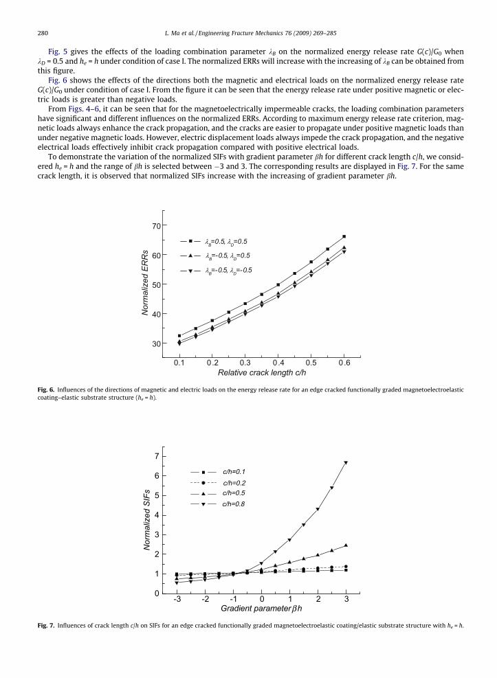
Fig. 6 shows the effects of the directions both the magnetic and electrical loads on the normalized energy release rateG(c)/G0 under condition of case I. From the figure it can be seen that the energy release rate under positive magnetic or elec-tric loads is greater than negative loads.
From Figs. 4–6, it can be seen that for the magnetoelectrically impermeable cracks, the loading combination parametershave significant and different influences on the normalized ERRs. According to maximum energy release rate criterion, mag-netic loads always enhance the crack propagation, and the cracks are easier to propagate under positive magnetic loads thanunder negative magnetic loads. However, electric displacement loads always impede the crack propagation, and the negativeelectrical loads effectively inhibit crack propagation compared with positive electrical loads.
To demonstrate the variation of the normalized SIFs with gradient parameter bh for different crack length c/h, we consid-ered he = h and the range of bh is selected between �3 and 3. The corresponding results are displayed in Fig. 7. For the samecrack length, it is observed that normalized SIFs increase with the increasing of gradient parameter bh.
0.1 0.2 0.3 0.4 0.5 0.6
30
40
50
60
70
Nor
mal
ized
ER
Rs
Relative crack length c/h
λB=0.5, λD=0.5
λB=-0.5, λD=0.5
λB=-0.5, λD=-0.5
Fig. 6. Influences of the directions of magnetic and electric loads on the energy release rate for an edge cracked functionally graded magnetoelectroelasticcoating–elastic substrate structure (he = h).
-3 -2 -1 0 1 2 30
1
2
3
4
5
6
7
Nor
mal
ized
SIF
s
Gradient parameter h
c/h=0.1c/h=0.2c/h=0.5c/h=0.8
β
Fig. 7. Influences of crack length c/h on SIFs for an edge cracked functionally graded magnetoelectroelastic coating/elastic substrate structure with he = h.

L. Ma et al. / Engineering Fracture Mechanics 76 (2009) 269–285 281
9. Conclusions
A surface crack in a functionally graded magnetoelectroelastic strip bonded to an elastic layer is considered. Bothimpermeable and permeable crack assumption are considered for the electrically/magnetically insulated and electri-cally/magnetically grounded elastic layer. For the magnetoelectrically impermeable cracks, the SIFs, the EDIFs and MIIFsare, respectively, related to applied mechanical loads, electrical loads and magnetic loads only. The ERRs depend on bothapplied loads including mechanical, electrical and magnetic loads and material parameters. For the magnetoelectricallypermeable cracks, both magnetic and electrical loads have no contribution to ERRs and field intensity factors. In general,the value of the normalized ERRs for magnetoelectrically permeable cracks are generally higher than that impermeablecase under only mechanical loading. For the magnetoelectrically impermeable cracks, the loading combination parametershave significant and different influences on the normalized ERRs. According to maximum energy release rate criterion,magnetic loads always enhance the crack propagation. However, electric displacement loads always impede the crackpropagation.
Acknowledgements
The present work is supported by National Science Foundation of China under Grant No. 10502017 and under Grant No.10432030. The authors are grateful for the reviewers for their valuable comments in improving the paper.
Appendix A
Case I:
A2ðsÞ ¼1
Q 1ðsÞ
Z c
0T1ðs; tÞgwðs; tÞdt ðA1Þ
A3ðsÞ ¼1
Q 1ðsÞ
Z c
0T2ðs; tÞgwðs; tÞdt ðA2Þ
B2ðsÞ ¼1
Q 2ðsÞ
Z c
0T3ðs; tÞgeeg
w/wðs; tÞdt ðA3Þ
B3ðsÞ ¼1
Q 3ðsÞ
Z c
0T4ðs; tÞgeeg
w/wðs; tÞdt ðA4Þ
C2ðsÞ ¼1
Q 2ðsÞ
Z c
0T3ðs; tÞgfgl
w/wðs; tÞdt ðA5Þ
C3ðsÞ ¼1
Q 3ðsÞ
Z c
0T4ðs; tÞgfgl
w/wðs; tÞdt ðA6Þ
D1ðsÞ ¼1
PðsÞ
Z c
0Qðs; tÞgwðs; tÞdt ðA7Þ
D2ðsÞ ¼e2sðhþheÞ
PðsÞ
Z c
0Qðs; tÞgwðs; tÞdt ðA8Þ
where
nðsÞ ¼ sce
44
m10ebh
esh � eshþ2she
esh þ eshþ2sheðA9Þ
Q 1ðsÞ ¼ m3ðsÞ½m2ðsÞ � nðsÞ�em2ðsÞh �m2ðsÞ½m3ðsÞ � nðsÞ�em3ðsÞh ðA10Þ
Q 2ðsÞ ¼ em2ðsÞh � em3ðsÞh� �
m2ðsÞ ðA11Þ
Q 3ðsÞ ¼ em2ðsÞh � em3ðsÞh� �
m3ðsÞ ðA12Þ
T1ðs; tÞ ¼ m3ðsÞ½F2ðs; tÞ � nðsÞF3ðs; tÞ� � ½m3ðsÞ � nðsÞ�em3ðsÞhF1ðs; tÞ ðA13Þ
T2ðs; tÞ ¼ ½m2ðsÞ � nðsÞ�em2ðsÞhF1ðs; tÞ �m2ðsÞ½F2ðs; tÞ � nðsÞF3ðs; tÞ� ðA14Þ
T3ðs; tÞ ¼ F2ðs; tÞ � em3ðsÞhF1ðs; tÞ ðA15Þ
T4ðs; tÞ ¼ em2ðsÞhF1ðs; tÞ � F2ðs; tÞ ðA16Þ
PðsÞ ¼ ðesh þ e2she ÞQ1ðsÞ ðA17Þ
Qðs; tÞ ¼ em2ðsÞhT1 þ em3ðsÞhT2 ðA18Þ

282 L. Ma et al. / Engineering Fracture Mechanics 76 (2009) 269–285
Case II:
A2ðsÞ ¼k1l4 � k2l2
l1l4 � l2l3ðA19Þ
A3ðsÞ ¼1
m3
Z c
0g1F1dt �m2
m3
k1l4 � k2l2
l1l4 � l2l3ðA20Þ
B2ðsÞ ¼k2l1 � k1l3
l1l4 � l2l3ðA21Þ
B3ðsÞ ¼1
m3
Z c
0geeg
w/wF1dt �m2
m3
k2l1 � k1l3l1l4 � l2l3
ðA22Þ
C2ðsÞ ¼ðl1l4 � l2l3Þc3 � ðk1l4 � k2l2Þq1 � ðk2l1 � k1l3Þq2
ðl1l4 � l2l3Þq3ðA23Þ
C3ðsÞ ¼1
m3
Z c
0gfgl
w/wF1dt �m2
m3
ðl1l4 � l2l3Þc3 � ðk1l4 � k2l2Þq1 � ðk2l1 � k1l3Þq2
ðl1l4 � l2l3Þq3ðA24Þ
D1ðsÞ ¼A2em2h þ A3em3h �
R ba g1F3dt
eshð1þ e2she Þ ðA25Þ
D2ðsÞ ¼ D1ðsÞe2sðhþheÞ ðA26Þ
where
nðsÞ ¼ sce44
1� e2she
1þ e2sheðA27Þ
pðs; tÞ ¼ F2ðs; tÞ � em3ðsÞhF1ðs; tÞm2ðsÞ½em2ðsÞh � em3ðsÞh� ðA28Þ
q1ðsÞ ¼ ½m10m2ðsÞ � nðsÞ�em2ðsÞh �m2ðsÞ½m10m3ðsÞ � nðsÞ�em3ðsÞh
m3ðsÞðA29Þ
q2ðsÞ ¼ m20m2ðsÞ½em2ðsÞh � em3ðsÞh� ðA30Þ
q3ðsÞ ¼ m30m2ðsÞ½em2ðsÞh � em3ðsÞh� ðA31Þ
q4ðs; tÞ ¼ c440F2ðs; tÞ � nðsÞF3ðs; tÞ �c440m3ðsÞ � nðsÞem3ðsÞh
m3ðsÞF1ðs; tÞ ðA32Þ
q5ðs; tÞ ¼ e150½F2ðs; tÞ � F1ðs; tÞ� ðA33Þ
q6ðs; tÞ ¼ f150½F2ðs; tÞ � F1ðs; tÞ� ðA34Þ
c1ðsÞ ¼Z c
0pðs; tÞg/ðtÞdt ðA35Þ
c2ðsÞ ¼Z c
0pðs; tÞgwðtÞdt ðA36Þ
c3ðsÞ ¼Z c
0½q4ðs; tÞgwðtÞ þ q5ðs; tÞg/ðtÞ þ q6ðs; tÞgwðtÞ�dt ðA37Þ
k1ðsÞ ¼ c1ðsÞ � f1c3ðsÞq3ðsÞ
ðA38Þ
k2ðsÞ ¼ c2ðsÞ � f2c3ðsÞq3ðsÞ
ðA39Þ
l1ðsÞ ¼ d1 �q1ðsÞq3ðsÞ
f1 ðA40Þ
l2ðsÞ ¼ e1 �q2ðsÞq3ðsÞ
f1 ðA41Þ
l3ðsÞ ¼ d2 �q1ðsÞq3ðsÞ
f2 ðA42Þ
l4ðsÞ ¼ e2 �q2ðsÞq3ðsÞ
f2 ðA43Þ
L. Ma et al. / Engineering Fracture Mechanics 76 (2009) 269–285 283
Appendix B 2 3
½H0� ¼c44 e15 f15
e15 �e11 �g11
f15 �g11 �l11
664 775 ðB1Þ
G0ð1;1Þ ¼ ðm10d2w þm20c2w þm30k2wÞem2ðsÞx þ ðm10d3w þm20c3w þm30k3wÞem3ðsÞx ðB2aÞG0ð1;2Þ ¼ ðm10d2/ þm20c2/ þm30k2/Þem2ðsÞx þ ðm10d3/ þm20c3/ þm30k3/Þem3ðsÞx ðB2bÞG0ð1;3Þ ¼ ðm10d2w þm20c2w þm30k2wÞem2ðsÞx þ ðm10d3w þm20c3w þm30k3wÞem3ðsÞx ðB2cÞG0ð2;1Þ ¼ c2wem2ðsÞx þ c3wem3ðsÞx ðB2dÞG0ð2;2Þ ¼ c2/em2ðsÞx þ c3/em3ðsÞx ðB2eÞG0ð2;3Þ ¼ c2wem2ðsÞx þ c3wem3ðsÞx ðB2fÞG0ð3;1Þ ¼ k2wem2ðsÞx þ k3wem3ðsÞx ðB2gÞG0ð3;2Þ ¼ k2/em2ðsÞx þ k3/em3ðsÞx ðB2hÞG0ð3;3Þ ¼ k2wem2ðsÞx þ k3wem3ðsÞx ðB2iÞ
Case I:
d2wðs; tÞ ¼ sT1ðs; tÞQ 1ðsÞ
ðB3Þ
c2wðs; tÞ ¼ e150sT3ðs; tÞQ 2ðsÞ
ðB4Þ
k2wðs; tÞ ¼ f150sT3ðs; tÞQ2ðsÞ
ðB5Þ
d2/ðs; tÞ ¼ 0 ðB6Þ
c2/ðs; tÞ ¼ �e110sT3ðs; tÞQ 2ðsÞ
ðB7Þ
k2/ðs; tÞ ¼ �g110sT3ðs; tÞQ2ðsÞ
ðB8Þ
d2wðs; tÞ ¼ 0 ðB9Þ
c2wðs; tÞ ¼ �g110sT3ðs; tÞQ 2ðsÞ
ðB10Þ
k2wðs; tÞ ¼ �l110sT3ðs; tÞQ 2ðsÞ
ðB11Þ
d3wðs; tÞ ¼ sT2ðs; tÞQ 1ðsÞ
ðB12Þ
c3wðs; tÞ ¼ e150sT4ðs; tÞQ 3ðsÞ
ðB13Þ
k3wðs; tÞ ¼ f150sT4ðs; tÞQ3ðsÞ
ðB14Þ
d3/ðs; tÞ ¼ 0 ðB15Þ
c3/ðs; tÞ ¼ �e110sT4ðs; tÞQ 3ðsÞ
ðB16Þ
k3/ðs; tÞ ¼ �g110sT4ðs; tÞQ3ðsÞ
ðB17Þ
d3wðs; tÞ ¼ 0 ðB18Þ
c3wðs; tÞ ¼ �g110sT4ðs; tÞQ 3ðsÞ
ðB19Þ
k3wðs; tÞ ¼ �l110sT4ðs; tÞQ 3ðsÞ
ðB20Þ

284 L. Ma et al. / Engineering Fracture Mechanics 76 (2009) 269–285
Case II:
d2wðs; tÞ ¼½f2l2ðsÞ � f1l4ðsÞ�q4ðs; tÞ½l1ðsÞl4ðsÞ � l2ðsÞl3ðsÞ�q3ðsÞ
ðB21Þ
d2/ðs; tÞ ¼½f2l2ðsÞ � f1l4ðsÞ�q5ðs; tÞ½l1ðsÞl4ðsÞ � l2ðsÞl3ðsÞ�q3ðsÞ
þ l4ðsÞpðsÞ ðB22Þ
d2wðs; tÞ ¼½f2l2ðsÞ � f1l4ðsÞ�q6ðs; tÞ½l1ðsÞl4ðsÞ � l2ðsÞl3ðsÞ�q3ðsÞ
� l2ðsÞpðsÞ ðB23Þ
c2wðs; tÞ ¼½f1l3ðsÞ � f2l1ðsÞ�q4ðs; tÞ½l1ðsÞl4ðsÞ � l2ðsÞl3ðsÞ�q3ðsÞ
ðB24Þ
c2/ðs; tÞ ¼½f1l3ðsÞ � f2l1ðsÞ�q5ðs; tÞ½l1ðsÞl4ðsÞ � l2ðsÞl3ðsÞ�q3ðsÞ
� l3ðsÞpðsÞ ðB25Þ
c2wðs; tÞ ¼½f1l3ðsÞ � f2l1ðsÞ�q6ðs; tÞ½l1ðsÞl4ðsÞ � l2ðsÞl3ðsÞ�q3ðsÞ
þ l1ðsÞpðsÞ ðB26Þ
k2wðs; tÞ ¼q4
q3� f½q2l3 � q1l4�f1 þ ½q1l2 � q2l1�f2gq4
½l1l4 � l2l3�q23
ðB27Þ
k2/ðs; tÞ ¼q5
q3� f½q2l3 � q1l4�f1 þ ½q1l2 � q2l1�f2gq5
½l1l4 � l2l3�q23
þ ½q2l3 � q1l4�p½l1l4 � l2l3�q3
ðB28Þ
k2wðs; tÞ ¼q6ðs; tÞq3ðsÞ
� f½q2ðsÞl3ðsÞ � q1ðsÞl4ðsÞ�f1 þ ½q1ðsÞl2ðsÞ � q2ðsÞl1ðsÞ�f2gq6ðs; tÞ½l1ðsÞl4ðsÞ � l2ðsÞl3ðsÞ�q2
3ðsÞ
þ ½q1ðsÞl2ðsÞ � q2ðsÞl1ðsÞ�p½l1ðsÞl4ðsÞ � l2ðsÞl3ðsÞ�q3ðsÞ
ðB29Þ
d3wðs; tÞ ¼F1ðs; tÞm3ðsÞ
�m2ðsÞm3ðsÞ
d2wðs; tÞ ðB30Þ
d3/ðs; tÞ ¼ �m2ðsÞm3ðsÞ
d2/ðs; tÞ ðB31Þ
d3wðs; tÞ ¼ �m2ðsÞm3ðsÞ
d2wðs; tÞ ðB32Þ
c3wðs; tÞ ¼ e150F1ðs; tÞm3ðsÞ
�m2ðsÞm3ðsÞ
c2wðs; tÞ ðB33Þ
c3/ðs; tÞ ¼ �e110F1ðs; tÞm3ðsÞ
�m2ðsÞm3ðsÞ
c2/ðs; tÞ ðB34Þ
c3wðs; tÞ ¼ �g110F1ðs; tÞm3ðsÞ
�m2ðsÞm3ðsÞ
c2wðs; tÞ ðB35Þ
k3wðs; tÞ ¼ f150F1ðs; tÞm3ðsÞ
�m2ðsÞm3ðsÞ
k2wðs; tÞ ðB36Þ
c3/ðs; tÞ ¼ �g110F1ðs; tÞm3ðsÞ
�m2ðsÞm3ðsÞ
k2/ðs; tÞ ðB37Þ
k3wðs; tÞ ¼ �l110F1ðs; tÞm3ðsÞ
�m2ðsÞm3ðsÞ
k2wðs; tÞ ðB38Þ
References
[1] Van Run AMJG, Terrell DR, Scholing JH. An in situ grown eutectic magneto-electric composite material. J Mater Sci 1974;9:1710–4.[2] Gao CF, Tong P, Zhang TY. Fracture mechanics for a mode III crack in a magnetoelectroelastic solid. Int J Solids Struct 2004;41:6613–29.[3] Nan CW. Magnetoelectric effect in composites of piezoelectric and piezomagnetic phases. Phys Rev B 1994;50:6082–8.[4] Huang JH, Liu HK, Dai WL. The optimized fiber volume fraction for magnetoelectric coupling effect in piezoelectric–piezomagnetic continuous fiber
reinforced composites. Int J Engng Sci 2000;38:1207–17.[5] Li JY. Magnetoelectroelastic multi-inclusion and inhomogeneity problems and their applications in composite materials. Int J Engng Sci
2000;38:1993–2011.[6] Soh AK, Liu JX, Hoon KH. Three-dimensional Green’s functions for transversely isotropic magnetoelectroelastic solids. Int J Nonlinear Sci Numer
Simulat 2003;4:139–48.[7] Song ZF, Sih GC. Crack initiation behavior in a magnetoelectroelastic composite under in-plane deformation. Theor Appl Fract Mech 2003;39:189–207.[8] Gao CF, Hannes K, Herbert B. Crack problems in magnetoelectroelastic solids: Part I. Exact solution of a crack. Int J Engng Sci 2003;41:969–81.[9] Wang BL, Mai YW. Crack tip field in piezoelectric/piezomagnetic media. Eur J Mech A – Solids 2003;22:591–602.
[10] Wang BL, Mai YW. Fracture of piezoelectromagnetic materials. Mech Res Commun 2004;31:65–73.[11] Gupta GD, Erdogan F. The problem of edge crack in an infinite strip. ASME J Appl Mech 1974;41:1001–6.[12] Delale F, Erdogan F. The problem of internal and edge crack in an orthotropic strip. ASME J Appl Mech 1977;44:237–42.[13] Zhong XC, Li XF. Closed-form solution for an eccentric anti-plane shear crack normal to the edges of a magnetoelectroelastic strip. Acta Mech
2006;186:1–15.

L. Ma et al. / Engineering Fracture Mechanics 76 (2009) 269–285 285
[14] Wang BL, Mai YW. Exact and fundamental solution for an anti-plane crack vertical to the boundaries of a magnetoelectroelastic strip. Int J DamageMech 2007;16:77–94.
[15] Yong HD, Zhou YH. Transient response of a cracked magnetoelectroelastic strip under anti-plane impact. Int J Solids Struct 2007;44:705–17.[16] Ma L, Li J, Abdelmoula R, Wu L-Z. Mode III crack problem in a functionally graded magneto-electro-elastic strip. Int J Solids Struct
2007;44(17):5518–37.[17] Feng WJ, Su RKL. Dynamic internal crack problem of a functionally graded magneto-electro-elastic strip. Int J Solids Struct 2006;43:5196–216.[18] Feng WJ, Su RKL. Dynamic fracture behaviors of cracks in a functionally graded magneto-electro-elastic plate. Eur J Mech A – Solids 2007;26:363–79.[19] Erdogan F, Wu BH. Crack problem in FGM layer under thermal stresses. J Therm Stresses 1996;19:237–65.[20] Wang BL, Mai YW, Sun Y-G. Surface cracking of a piezoelectric strip bonded to an elastic substrate (mode I crack problem). Arch Appl Mech
2003;73:434–47.[21] Chen J, Liu Z-X. Transient response of a mode III crack in an orthotropic functionally graded strip. Eur J Mech A – Solids 2005;24:325–36.[22] Erdogan F, Gupta GD, Cook TS. Methods of analysis and solution of crack problem. Mechanics of fracture, vol. 1. Leyden: Noordoff; 1972.[23] Pak YE. Crack extension force in a piezoelectric material. ASME J Appl Mech 1990;57:647–53.[24] Wang XY, Yu SW. Transient response of a crack in a piezoelectric strip objected to the mechanical and electrical impacts: Mode III problem. Int J Solids
Struct 2000;37:5795–808.[25] Li JY, Dunn ML. Micromechanics of magnetoelectroelastic composite materials: average field and effective behavior. J Intell Mater Syst Struct
1998;9:404–16.[26] Wu TL, Huang JH. Closed-form solutions for the magnetoelectric coupling coefficients in fibrous composites with piezoelectric and piezomagnetic
phases. Int J Solids Struct 2000;37:2981–3009.[27] Aboudi J. Mircomechanical analysis of fully coupled electro-magneto-thermo-elastic multiphase composites. Smart Mater Struct 2001;10:867–77.[28] Chen ZR, Yu SW, Meng L, Lin Y. Effective properties of layered magneto-electro-elastic composites. Compos Struct 2002;57:177–82.[29] Sih GC, Song ZF. Magnetic and electric poling effects associated with crack growth in BaTiO3–CoFe2O4 composite. Theor Appl Fract Mech
2003;39:209–77.