supplementary model 7-20 multiflex fire ... - c … · supplementary model 7"-20"...
TRANSCRIPT

SUPPLEMENTARY
MODEL 7"-20" MULTIFLEX
FIRE BARRIER
INSTALLATION INSTRUCTIONS
IMPORTANT:
READ THROUGH ALL INSTRUCTIONS PRIOR TO STARTING INSTALLATION
Prior to the commencement of Installation all materials MUST be
inspected for Damage. Any damage must be reported to Construction
Specialties as soon as possible, so that replacement materials may be
furnished without delay.
All work must be completed as per Architect's Approved "Shop
Drawings", and in accordance with these Installation Instructions. When
installation is complete, all materials must be protected from damage
until the Architect's FINAL INSPECTION.
IMPORTANT
INFORMATION
All materials should be arranged in the order that they are
to be installed. All hardware required for each portion of
the work should be placed with the appropriate materials.
Please review all Approved Shop Drawings and this
Document to familiarize yourself with all the details and
components of this assembly.
10/9/14
12CN
SURFACE MOUNT
FLANGE
MULTIFLEX FIRE
BARRIER
FLOOR SLAB
NOMINAL JOINT WIDTH
14"-20" NOMINAL
DOUBLE DRAPE SYSTEM
7"-12" NOMINAL
SINGLE DRAPE SYSTEM
This document is the property of Construction Specialties, Inc. and contains
CONFIDENTIAL PROPRIETARY INFORMATION that is not to be disclosed to
third parties and is not to be used without approval in writing from
Construction Specialties, Inc.

General Instructions:
* Fire Barriers must be installed in accordance with installation instructions to maintain UL Rating.
* These instructions are for all horizontal and vertical Multiflex installations for 7"-20" nominal joint widths.
* The 7"-12" nominal joint width barriers are a single draped system.
* The 14"-20" nominal joint width barriers are a double draped system as shown.
* The galvanized flanges are welded to the fire barriers and are always required for installation.
* Typically, the same fasteners can be used to fasten the cover plate mechanism and the fire barriers.
* If splicing is required, see the separate splicing instructions.
* Wear heavy duty work gloves and eye protection during the entire installation process.
Packaging:
Each carton contains: 10 foot lengths (custom lengths are also available) of the Multiflex Fire Barrier with the galvanized
flanges attached.
One kit with the necessary material for splicing.
Material Preparation:
Set the product out face up (the side with the UL label) and cut to length. The insulation portion of the product can be
formed into a "U" or "V" shape to help it fit into the expansion joint. This can be done by crimping the insulation along the
center line with a pipe or board (optional) (See Fig. A).
GENERAL NOTES
CRIMP AT CENTER
OF INSULATION
TO HELP FACILITATE
INSTALLATION
Fig. A
Material Preparation
GALVANIZED
FLANGE
ATTACHED
PAGE 2

HORIZONTAL or FLOOR AND ROOF JOINTS
Single Fire Barrier Installation: 7"-12" Nominal Joint Widths
STEP 1
After completing material preparation described on page 2 and as shown in Fig. A, place the Fire Barrier into the expansion joint cavity.
Drill the appropriate size holes and secure the flanges with fasteners with a maximum spacing of 18 inches (See Figs. B & C).
STEP 2
Install the expansion joint covers (reference expansion joint cover instructions) over the joint or in the blockout with appropriate fasteners.
Fig. B - Single Barrier
Surface Mount Flange (SM)
Fig. C - Single Barrier
Low Profile Flange (LP)
Double Barrier Installation: 14"-20" Nominal Joint Widths
STEP 1
After completing material preparation described on page 2 and as shown in Fig. A, place the lower Fire Barrier into the expansion joint
cavity (See Figs. D & E).
Optional: Prior to installing the upper Fire Barrier, if the lower Fire Barrier requires fastening to hold it in place, drill appropriate size holes
to the flanges and secure with fasteners.
STEP 2
Install the upper Fire Barrier and drill the appropriate size holes as shown in Fig. D. The fasteners need to be installed with a maximum
spacing of 18 inches. The same fasteners used to install the cover mechanism can generally be used to install the Fire Barriers.
Fire Barriers with Low Profile flanges are secured with fasteners inside the joint cavity (See Fig. E).
Note: Fire Barriers with Surface Mount flanges can also be secured with fasteners inside the joint cavity.
STEP 3
Install the expansion joint covers (reference expansion joint cover instructions) over the joint or in the blockout with appropriate fasteners.
Fig. D - Double Barrier
Surface Mount Flange (SM)
Fig. E - Double Barrier
Low Profile Flange (LP)
OPTIONAL
OPTIONAL
PAGE 3

FLOOR to WALL & ROOF to WALL
OPTIONAL
Single Fire Barrier Installation: 7"-12" Nominal Joint Widths
STEP 1
After completing material preparation described on page 2 and as shown in Fig. A, place the Fire Barrier into the expansion joint cavity.
Drill the appropriate size holes and secure the flanges with fasteners with a maximum spacing of 18 inches (See Figs. F & G).
STEP 2
Install the expansion joint covers (reference expansion joint cover instructions) over the joint or in the blockout with appropriate fasteners.
Double Barrier Installation: 14"-20" Nominal Joint Widths
STEP 1
After completing material preparation described on page 2 and as shown in Fig. A, place the lower Fire Barrier into the expansion joint
cavity (See Figs. H & I).
Optional: Prior to installing the upper Fire Barrier, if the lower Fire Barrier requires fastening to hold it in place, drill appropriate size holes
to the flanges and secure with fasteners.
STEP 2
Install the upper Fire Barrier and drill the appropriate size holes as shown in Fig. H. The fasteners need to be installed with a maximum
spacing of 18 inches. The same fasteners used to install the cover mechanism can generally be used to install the Fire Barriers.
Fire Barriers with Low Profile flanges are secured with fasteners inside the joint cavity (See Fig. I).
Note: Fire Barriers with Surface Mount flanges can also be secured with fasteners inside the joint cavity.
STEP 3
Install the expansion joint covers (reference expansion joint cover instructions) over the joint or in the blockout with appropriate fasteners.
Fig. F - Single Barrier
Surface Mount Flange (SM)
Fig. G - Single Barrier
Low Profile Flange (LP)
Fig. H - Double Barrier
Surface Mount Flange (SM)
Fig. I - Double Barrier
Low Profile Flange (LP)
OPTIONAL
PAGE 4

WALL JOINTS
Single Fire Barrier Installation: 7"-12" Nominal Joint Widths
STEP 1
After completing material preparation described on page 2 and as shown in Fig. A, place the Fire Barrier into the expansion joint cavity.
Drill the appropriate size holes and secure the flanges with fasteners with a maximum spacing of 18 inches (See Figs. J & K).
STEP 2
Install the expansion joint covers (reference expansion joint cover instructions) to either side or both sides of the wall when accessible
with appropriate fasteners.
Fig. J - Single Barrier
Surface Mount Flange (SM)
Fig. K - Single Barrier
Low Profile Flange (LP)
Double Barrier Installation: 14"-20" Nominal Joint Widths
After completing material preparation described on page 2 and as shown in Fig. A, place the inner Fire barrier into the expansion joint
cavity (See Figs. L & M).
Optional: Prior to installing the outer Fire Barrier, if the inner Fire Barrier requires fastening to hold it in place, drill appropriate size holes to
the flanges and secure with fasteners.
STEP 2
Install the outer Fire Barrier and drill the appropriate size holes as shown in Fig. L. The fasteners need to be installed with a maximum
spacing of 18 inches. The same fasteners used to install the cover mechanism can generally be used to install the Fire Barriers.
FireBarriers with Low Profile flanges are secured with fasteners inside the joint cavity (See Fig. M).
Note: Fire Barriers with Surface Mount flanges can also be secured with fasteners inside the joint cavity.
STEP 3
Install the expansion joint covers (reference expansion joint cover instructions) to either side or both sides of the wall when accessible with
appropriate fasteners.
Fig. L - Double Barrier
Surface Mount Flange (SM)
Fig. M - Double Barrier
Low Profile Flange (LP)
OPTIONAL OPTIONAL
PAGE 5

CORNER WALL JOINTS
Fig. P - Double Barrier
Surface Mount Flange (SM)
Fig. Q - Double Barrier
Low Profile Flange (LP)
Double Barrier Installation: 14"-20" Nominal Joint Widths
After completing material preparation described on page 2 and as shown in Fig. A, place the inner Fire Barrier into the expansion joint
cavity (See Figs. P & Q).
Optional: Prior to installing the outer Fire Barrier, if the inner Fire Barrier requires fastening to hold it in place, drill appropriate size holes to
the flanges and secure with fasteners.
STEP 2
Install the outer Fire Barrier and drill the appropriate size holes as shown in Fig. P. The fasteners need to be installed with a maximum
spacing of 18 inches. The same fasteners used to install the cover mechanism can generally be used to install the Fire Barriers.
Fire Barriers with Low Profile flanges are secured with fasteners inside the joint cavity (See Fig. Q).
Note: Fire Barriers with Surface Mount flanges can also be secured with fasteners inside the joint cavity.
STEP 3
Install the expansion joint covers (reference expansion joint cover instructions) to either side or both sides of the wall when accessible with
appropriate fasteners.
Fig. N - Single Barrier
Surface Mount Flange (SM)
Fig. O - Single Barrier
Low Profile Flange (LP)
Single Fire Barrier Installation: 7"-12" Nominal Joint Widths
STEP 1
After completing material preparation described on page 2 and as shown in Fig. A, place the Fire Barrier into the expansion joint cavity.
Drill the appropriate size holes and secure the flanges with fasteners with a maximum spacing of 18 inches (See Figs. N & O).
STEP 2
Install the expansion joint covers (reference expansion joint cover instructions) to either side or both sides of the wall when accessible
with appropriate fasteners.
OPTIONAL OPTIONAL
PAGE 6
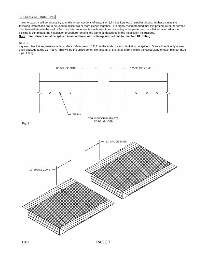
SPLICING INSTRUCTIONS
In some cases it will be necessary to make longer sections of expansion joint blankets out of smaller pieces. In these cases the
following instructions are to be used to splice two or more pieces together. It is highly recommended that this procedure be performed
prior to installation in the wall or floor, as this procedure is much less time consuming when performed on a flat surface. After the
splicing is completed, the installation procedure remains the same as described in the installation instructions.
Note: Fire Barriers must be spliced in accordance with splicing instructions to maintain UL Rating.
STEP 1
Lay each blanket segment on a flat surface. Measure out 12" from the ends of each blanket to be spliced. Draw a line directly across
each package at the 12" mark. This will be the splice zone. Remove all of the tie pins from within the splice zone of each blanket (See
Figs. 1 & 2).
Fig. 1
TIE PIN
TOP VIEW OF BLANKETS
TO BE SPLICED
Fig. 2
12" SPLICE ZONE
12" SPLICE ZONE
12" SPLICE ZONE 12" SPLICE ZONE
PAGE 7

SPLICING INSTRUCTIONS
STEP 2
Make a "tongue and groove" type splice by cutting away every other layer of insulation in the splice zone on each blanket segment and
save the scraps for future use. Make the opposite cuts on the other half of the splice. Trim the metallic septum layers the same length
as the insulation adjacent to them (See Figs. 3 & 4).
Note: If flanges are pre-welded to the blanket segments, the flanges must be cut back in one of the splice zones. Overlapping
galvanized flanges are not allowed.
Fig. 3
Cross-Section of Splice Zone
INSULATION LAYERS
Fig. 4
12" SPLICE ZONE 12" SPLICE ZONE
BOTTOM SCREEN AND FOIL
TOP SCREEN AND FOIL TOP SCREEN AND FOIL
Option 1
Trim back one flange and
butt the two flanges together.
Option 2
Do not trim back any flange and overlap two layers
of flange through the entire splice zone.
FLANGE
OVERLAP
FLANGE
OVERLAP
GALVANIZED
FLANGE
GALVANIZED
FLANGE
T
R
I
M
A
W
A
Y
PAGE 8

SPLICING INSTRUCTIONS
STEP 3
Assemble the two blanket segments, interweaving the insulation layers (See Figs. 5 & 6).
Fig. 5
Cross-Section of Splice Zone
INSULATION LAYERS
Fig. 6
12" SPLICE ZONE 12" SPLICE ZONE
BOTTOM SCREEN AND FOIL
TOP SCREEN AND FOIL TOP SCREEN AND FOIL
12" SPLICE ZONE
PAGE 9

SPLICING INSTRUCTIONS
STEP 4
Pin the four corners of the splice zone together, through the insulation and the foils, but not through the outer screen (See Figs. 7 & 8).
Place six equally spaced pins down the center of the splice zone, through the insulation, through all foil layers and both of the outer
screen layers (See Figs. 7 & 9).
Inspect the splice to ensure:
a. The splice does not have any gaps.
b. The splice is tied together with pins, down the center line, through the screen.
c. The four corner pins of the splice do not go through the screen.
After the splice has passed inspection, lay the scraps over the splice. These scraps were saved for future use during the completion of
Step 2 and should now be laid in over the splice for added thermal protection.
Fig. 7
Assembly of the Splice
INSULATION
LAYERS
Fig. 8
12" SPLICE ZONE 12" SPLICE ZONE
SCREEN
SIDE VIEW OF SPLICE
12"
SPLICE
ZONE
CORNER PINS
CENTER PINS
CENTER PINS
Fig. 9
TOP VIEW OF SPLICE
PAGE 10

90° INTERSECTION SPLICE
ISOMETRIC VIEW
PLAN VIEW
ELEVATION
OVERLAP
TIE PIN
TIE PIN
PAGE 11
** Note: SEE SPLICING INSTRUCTIONS 12ET
FOR MFX FIRE BARRIER 90° CORNER SPLICE

"T" INTERSECTION SPLICE
ISOMETRIC VIEW
PLAN VIEW
ELEVATION
TIE PIN
CONTINUOUS
FIRE BARRIER
TIE PIN
PAGE 12

4 WAY INTERSECTION SPLICE
ISOMETRIC VIEW
PLAN VIEW
ELEVATION
CONTINUOUS
FIRE BARRIER
TIE PIN
PAGE 13

CORRIDOR WRAP SPLICING DETAIL
HORIZONTAL FIRE BARRIER
VERTICAL FIRE BARRIER
SET VERTICAL INTO
HORIZONTAL FIRE
BARRIER
EXTEND HORIZONTAL
BARRIER PAST
VERTICAL BARRIER
MINIMUM 1"
PAGE 14
VERTICAL FIRE BARRIER TO
COPE INTO UNDERSIDE OF THE
HORIZONTAL FIRE BARRIER
NEST VERTICAL FIRE BARRIER
INTO HORIZONTAL FIRE BARRIER
TYPICAL
CLOSE ALL VOIDS
WITH CERAMIC FELT