supercritical water reactor (scwr) survey of materials experience
TRANSCRIPT

INEEL/EXT-03-00693Revision 1
Supercritical Water Reactor (SCWR)Survey of Materials Experience and R&D Needs to Assess Viability
September 2003
Idaho National Engineering and Environmental Laboratory Bechtel BWXT Idaho, LLC
INEEL/EXT-03-00693Revision 1
Supercritical Water Reactor (SCWR)
Survey of Materials Experience and R&D Needs to Assess Viability
Author(s)
Jacopo Buongiorno INEEL Robert Swindeman ORNL William Corwin ORNL Arthur Rowcliffe ORNL Philip Mac Donald INEEL Contractor Gary Was U. of Michigan Louis Mansur ORNL Dane Wilson ORNL
Randy Nanstad ORNL Ian Wright ORNL
September 2003
Idaho National Engineering and Environmental Laboratory
Idaho Falls, Idaho 83415
Prepared for the U.S. Department of Energy
Assistant Secretary Under DOE Idaho Operations Office
Contract DE-AC07-99ID13727

2
Executive Summary Supercritical water-cooled reactors (SCWRs) are among the most promising advanced nuclear systems because of their high thermal efficiency [i.e., about 45% vs. 33% of current light water reactors (LWRs)] and considerable plant simplification. SCWRs achieve this with superior thermodynamic conditions (i.e., high operating pressure and temperature), and by reducing the containment volume and eliminating the need for recirculation and jet pumps, pressurizer, steam generators, steam separators and dryers. The reference SCWR design in the U.S. is a direct cycle, thermal spectrum, light-water-cooled and moderated reactor with an operating pressure of 25 MPa and inlet/outlet coolant temperature of 280/500 C. The inlet flow splits, partly to a down-comer and partly to a plenum at the top of the reactor pressure vessel to flow downward through the core in special water rods to the inlet plenum. This strategy is employed to provide good moderation at the top of the core, where the coolant density is only about 15-20% that of liquid water. The SCWR uses a power conversion cycle similar to that used in supercritical fossil-fired plants: high- intermediate- and low-pressure turbines are employed with one moisture-separator re-heater and up to eight feedwater heaters. The reference power is 3575 MWt, the net electric power is 1600 MWe and the thermal efficiency is 44.8%. The fuel is low-enriched uranium oxide fuel and the plant is designed primarily for base load operation.
The purpose of this report is to survey existing materials for fossil, fission and fusion applications and identify the materials research and development needed to establish the SCWR viabilitya with regard to possible materials of construction. The two most significant materials related factors in going from the current LWR designs to the SCWR are the increase in outlet coolant temperature from 300 to 500 C and the possible compatibility issues associated with the supercritical water environment.
The following major components are discussed in Section 3 of this report:
Reactor pressure vessel Reactor pressure vessel internal components Pumps and piping Power conversion system
For each major component we discuss:
The status of the existing information The materials selection and development and qualification requirements The regulatory and codification requirements The materials testing and data base requirements The needed manufacturing infrastructure
The following paragraphs provide a brief summary of the findings in Section 3.
The reactor pressure vessel for the SCWR has an outer diameter of 6.3 m (20.5 ft), an overall height of 12.4 m (40.7 ft), and a shell thickness of 467 mm (18.4 in). The reactor pressure vessel includes two inlet nozzles and two outlet nozzles. The design pressure is 27.5 MPa (3990 psi) at a temperature of 280 ºC. To ensure vessel operation at 280 ºC, the design must include a feature to insulate the outlet nozzle from the outlet coolant temperature of 500 ºC. Given that the operating temperature and irradiation exposure a Viability research and development is that R&D necessary for proof of the basic concepts, technologies, and relevant conditions. Potential show stoppers are identified and resolved. The information generated at this stage of the R&D is sufficient for the conceptual design of a prototype.
3
are expected to be similar to that of current generation pressurized water reactors (PWRs), the primary candidate material for the reactor pressure vessel shell is the material currently used in PWRs for forgings, namely SA 508 Grade 3 Class 1. The greatest concern regarding the use of existing LWR materials is the ability to maintain through-thickness properties in the much thicker vessel sections required for the SCWR. The current design of the core height slightly exceeds the height of the largest forged rings made to date (4.3 versus about 4 m), but the Japan Steel Works has indicated that they expect to be able to build longer and thicker forgings with some modest changes in their equipment. They are more limited by the total weight of any given forging (about 600 t). The weight of a 4.3 m long SCWR forging would be about 285 t.
Regarding the thickness of the reactor pressure vessel shell, consideration should also be given to the potential use of higher strength materials that could result in a significant decrease of the required reactor pressure vessel wall thickness. Two potential materials are A508 Grade 4N Class 1 and a developmental steel, 3Cr-3WV. Given the same design pressure, use of a steel with a 50% higher strength would allow for more than a 30% reduction in shell thickness, which should significantly reduce the fabrication costs. Also, thinner sections are easier to inspect, the inspection results are more reliable, and the flaw density would likely be lower. However, significant additional mechanical property data would be needed for these materials to allow for their inclusion in the ASME Code, and irradiation effects data for all relevant mechanical properties would be required for licensing.
The reactor pressure vessel internals components include the fuel cladding, fuel rod spacers (spacer grid or wire wrap), water rod boxes, fuel assembly ducts, control rod guide thimbles, control rod guide tubes, the upper guide support plate, calandria tubes, upper core support plate, lower core plate, core former, core barrel, and threaded structural fasteners. All of these components will be designed to be replaceable. The structural materials recommended for these components are primarily ferritic-martensitic steels (e.g., T91, A-21, NF616, HCM12A), and low swelling variants of the austenitic stainless steels (e.g., D-9, PNC). Among the more advanced materials oxide-dispersion strengthened ferritic steels (e.g., MA-957) and ceramic composites (e.g., SiC-SiC) should be explored given their potential for superior high-temperature strength. Extensive R&D programs have been carried out in the U.S. under the auspices of the Liquid Metal Fast Breeder Reactor (LMFBR) Cladding and Duct program, the Fusion Materials Program and the Basic Energy Sciences Radiation Effects Program to both understand the mechanisms involved in neutron irradiation induced swelling and to develop new alloys with improved mechanical behavior relative to the austenitic stainless steels, such as AISI 304 and 316, currently used in LWRs. Many of these improved materials have been produced in a variety of product forms on a commercial scale. However, there is little basis at present for predicting the behavior of any of these materials in terms of their stress corrosion cracking and irradiation-assisted stress corrosion cracking (IASCC) behavior under supercritical water conditions. And, resistance to IASCC over the full range of supercritical water conditions will probably be the primary life-limiting factor for the permanent reactor components and to a lesser extent for the removable components. In fact, recent experiments at the University of Michigan have demonstrated that both 304L and 316L are susceptible to stress corrosion cracking in supercritical water, although the 304L is considerably more susceptible than the 316L (McKinley et al. 2003).
The materials program to identify materials solutions for each of the reactor internal components will include a) initial screening work b) stress corrosion cracking initiation and crack growth rate measurements utilizing material subjected to neutron and proton sources coupled with exposure to simulated supercritical water chemistry conditions and c) a series of neutron irradiation experiments to establish the mechanical behavior and dimensional stability of candidate alloys as a function of neutron dose and irradiation temperature. The primary component of the final phase of the R&D program will be the testing of a reduced number of promising candidate materials in a supercritical water loop in an

4
appropriate test reactor to obtain data on corrosion and IASCC resistance in prototypical conditions and provide important water chemistry control data. The initial screening step is critical to limiting the candidate materials to a reasonable number for subsequent testing while making sure that all appropriate materials are considered.
The issues and concerns regarding the pumps, valves, and piping for the SCWR can be divided into those associated with the feedwater line and the steam line piping systems. To some measure, issues characteristic of components of the feedwater line piping system will be similar to those being considered in the supercritical fossil-fired plants and also the boiling water reactors (BWRs). The SCWR feedwater pumps will be identical to those used in the supercritical fossil-fired plants, which have performed well. The choice between the ferritic steels and stainless steels for the feedwater line piping is one that must consider the chemistry of the water and the potential for flow assisted corrosion. Experience has shown that flow assisted corrosion is an important degradation mechanism in the feedwater carbon steel piping of both BWRs and PWRs. Also, high and low cycle fatigue are concerns. The issues related to the steam line piping system are more akin to those addressed in the design, construction, and operation of supercritical fossil power plants. Creep and time-dependent material degradation have been demonstrated to be active in the supercritical water-cooled fossil plant piping systems at temperatures above 370 ˚C(700 ˚F) for ferritic steels and above 425 ˚C (800 ˚F) for austenitic alloys. Materials used for the steam lines in supercritical fossil power plants and thus recommended for use in the SCWR include alloys P91 and P92. The main issue for these materials is their inclusion in Section III of the ASME code and the extension of the acceptable lifetime beyond the current 34 years allowed by the code (Subsection NH) for nuclear components operating at high temperature.
The major components of the power conversion system external to the reactor vessel (aside from the piping and pumps discussed above) include: the steam turbine and associated valving; the condenser; the demineralizer/condensate polisher; the feedwater heaters; and the deaerator. Because there are a large number of fossil-fired supercritical water-cooled power plants, there is a well-established manufacturing base for these components for operation at the steam conditions of interest in the SCWR, as well as extensive experience in their use. For the low temperature components and the feedwater heaters carbon steel is recommended as the primary structural material (with appropriate oxygen control). Turbine rotor, disc, blade, and vane problems have been experienced in steam turbines in both fossil and nuclear applications. Some of these problems are related to stress corrosion cracking of the CrMo and NiCrMoV steels used in these components, especially in crevices where corrosion products accumulate. Also, erosion by water droplets and solid particles is possible at certain vane and blade locations. In the SCWR system, a major concern is the solubility of the materials that will be in contact with the fluid, and the extent that these species and/or exfoliated corrosion products will be transported to the external circuit, where they may be deposited in the turbine or be accumulated in the demineralizer. The main area of unknown is the quantification of the solubility/corrosion in the prevailing water chemistry and at the higher temperature employed in the SCWR, compared to BWR experience. The challenge posed in the control of the water condition is one of balancing the requirements for minimizing corrosion and corrosion product deposition in the heat absorption part of the circuit, while limiting the carryover in the steam of salts likely to pose problems in the turbine.

5
The needed materials development tasks, schedules, and costs to assess the feasibility of the SCWR are presented in Section 4 of the report. The costs for the needed work for the SCWR are summarized below:
Component Costs (millions) Reactor pressure vessel 21. Reactor pressure vessel internal components 150. Pumps and piping 32. Power conversion system 15.
Total Costs $218.
The total cost estimate for development of the needed materials for the SCWR is about $218 million dollars. These costs will be lower if (1) existing university facilities are used, (2) the costs are shared with our international GIF partners, and/or (3) the costs are shared with other Generation IV reactor development programs. Note that these costs are for “viability” research and development as defined in the Generation IV Roadmap (GIF 2002). Viability research and development examines the feasibility of key technologies and is that R&D necessary for proof of the basic concepts, technologies, and relevant conditions. Potential showstoppers are identified and resolved. The information generated at this stage of the R&D is sufficient for the conceptual design of a prototype. It is not sufficient for the final design of the plant.
We conclude that there are significant materials development and qualification needs for the SCWR, but existing materials have been identified that could meet the requirements of all the SCWR components and subsystems.

6
ACKNOWLEDGEMENTSThe following persons are acknowledged for their helpful review of the report:
Dr. Todd Allen, University of Wisconsin at Madison Dr. Peter Andresen, General Electric Company Prof. Ronald Ballinger, MIT Dr. David Bartels, Notre Dame University Mr. Larry Conway, Westinghouse Electric Company Dr. Herbert Feinroth, Gamma Engineering Dr. Sue Lesica, DOE-NE Dr. Luca Oriani, Westinghouse Electric Company Dr. Kumar Sridharan, University of Wisconsin at Madison Dr. Terri Totemeier, INEEL

7
Contents
EXECUTIVE SUMMARY ........................................................................................................................ 2
ACKNOWLEDGEMENTS ....................................................................................................................... 6
CONTENTS ................................................................................................................................................ 7
1. INTRODUCTION.................................................................................................................................. 9
2. REACTOR DESCRIPTION............................................................................................................... 15
2.1. REFERENCE DESIGN POWER AND COOLANT CONDITIONS ............................................................. 152.2. SCWR REACTOR PRESSURE VESSEL.............................................................................................. 162.3. SCWR CORE AND FUEL ASSEMBLY DESIGN ....................................................................... 162.4. REACTOR PRESSURE VESSEL INTERNALS ....................................................................................... 182.5. CONTAINMENT DESIGN............................................................................................................ 192.6. POWER CONVERSION CYCLE........................................................................................................... 21
3. SCWR REACTOR SYSTEM MATERIALS DATA NEEDS ......................................................... 25
3.1. SUPERCRITICAL WATER CHEMISTRY AND CORROSION ISSUES ................................... 253.1.1. Supercritical Fossil Plant Water Quality Control ................................................................... 253.1.2. LWR Water Quality Control .................................................................................................... 263.1.2. Water Chemistry and Corrosion Issues in SCWRs .................................................................. 27
3.2. REACTOR PRESSURE VESSEL.................................................................................................. 283.2.1. Status........................................................................................................................................ 283.2.2. Materials Selection and Development and Qualification Requirements ................................. 29
3.2.2.1. Considerations for a SCWR RPV Design with an Insulated Nozzle ................................ 293.2.2.2. Material Considerations for a SCWR RPV Design with an Uninsulated Nozzle ............. 303.2.2.3. Consideration of Higher Strength Steels........................................................................... 31
3.2.3. Regulatory and Codification Requirements ............................................................................. 333.2.4. Materials Testing and Data Base Requirements...................................................................... 333.2.5. Industrial Base and Infrastructure Requirements.................................................................... 34
3.3. REACTOR PRESSURE VESSEL INTERNAL COMPONENTS ....................................................... 343.3.1. Status........................................................................................................................................ 373.3.2. Materials Selection and Development and Qualification Requirements ................................. 403.3.3. Regulatory and Codification Requirements ............................................................................. 423.3.4. Materials Testing and Database Requirements ....................................................................... 423.3.5. Manufacturing Infrastructure Required................................................................................... 45
3.4. PUMPS AND PIPING.................................................................................................................... 453.4.1. Feedwater Pumps..................................................................................................................... 46
3.4.1.1. Status................................................................................................................................. 463.4.1.2. Materials Selection and Development and Qualification Requirements........................... 463.4.1.3. Regulatory and Codification Requirements ...................................................................... 463.4.1.4. Materials Testing and Data Base Requirements ............................................................... 463.4.1.5. Manufacturing Infrastructure Required............................................................................. 47
3.4.2. Piping....................................................................................................................................... 473.4.2.1. Status................................................................................................................................. 473.4.2.2. Materials Selection and Development and Qualification Requirements........................... 473.4.2.3. Regulatory and Codification Requirements ...................................................................... 48

8
3.4.2.4. Materials Testing and Data Base Requirements ............................................................... 483.4.2.5. Manufacturing Infrastructure Required............................................................................. 48
3.5. POWER CONVERSION SYSTEM ............................................................................................... 493.5.1. Turbine..................................................................................................................................... 49
3.5.1.1. Status................................................................................................................................. 493.5.1.2. Materials Selection and Development and Qualification Requirements........................... 503.5.1.3. Regulatory and Codification Requirements ...................................................................... 533.5.1.4. Materials Testing and Data Base Requirements ............................................................... 533.5.1.5. Manufacturing Infrastructure Required............................................................................. 54
3.5.2. Condenser ................................................................................................................................ 543.5.2.1. Status................................................................................................................................. 543.5.2.2. Materials Selection and Development and Qualification Requirements........................... 553.5.2.3. Regulatory and Codification Requirements ...................................................................... 553.5.2.4. Materials Testing and Data Base Requirements ............................................................... 553.5.2.5. Manufacturing Infrastructure Required............................................................................. 55
4. SCWR MATERIALS DEVELOPMENT TASKS, COSTS, AND SCHEDULES ......................... 56
4.1. DEVELOPMENT TASKS, COSTS, AND SCHEDULES FOR THE SCWR REACTOR PRESSURE VESSEL MATERIALS ............................................................................................................................................. 564.2. DEVELOPMENT TASKS, COSTS, AND SCHEDULES FOR THE SCWR REACTOR PRESSUREVESSEL INTERNAL COMPONENT MATERIALS .................................................................................. 574.3. DEVELOPMENT TASKS, COSTS, AND SCHEDULES FOR THE SCWR PUMPS, VALVES, AND PIPING 594.4. DEVELOPMENT TASKS, COSTS, AND SCHEDULES FOR POWER CONVERSION SYSTEM MATERIALS.......................................................................................................................................... 60
REFERENCES.......................................................................................................................................... 61

9
1. Introduction Supercritical water cooled reactors (SCWRs) are a class of high temperature, high pressure water-cooled reactors that operate above the thermodynamic critical point of water (374 °C, 22.1 MPa or 705 °F, 3208 psia). These nuclear steam supply systems may have a predominantly thermal or fast neutron spectrum depending upon the specific core design. Both light water and heavy water moderation for the thermal spectrum versions have been proposed. The key advantages to the concept include:
Significant increases in thermal efficiency can be achieved relative to current generation light water reactors (LWRs). Estimated efficiencies for SCWRs are in the range of 44-45% compared to 32-34% for state-of-the-art LWRs.The higher enthalpy content of the SCW results in a much lower coolant mass flow rate per unit core thermal power. This leads to a reduction in the reactor coolant pumping power and smaller or fewer steam lines due to lower steam mass flow rates and higher steam density. A lower coolant mass inventory results from the reduced size of the system. This results in lower containment loadings during a design basis LOCA and the possibility of designing small containment buildings. No boiling crisis (i.e., departure from nucleate boiling or dry out) exists during normal operation due to lack of a second phase, thereby eliminating heat transfer regime discontinuities within the reactor core. However, an excessive increase in heat flux and/or decrease in coolant flow may cause a smooth heat transfer deterioration in SCWRs (depending on coolant geometry). Because the coolant does not undergo a change of phase, the need for steam dryers, steam separators, re-circulation and jet pumps, as well as steam generators, is eliminated.
It is important to point out that the thermal characteristics of the SCWR are unique. The primary system pressure is about 3 times the pressure in a boiling water reactors (BWR) and the coolant is a compressed liquid in the lower portion of the reactor core and it is a compressed gas in the upper portion of the core when it is at temperatures above the critical temperature. Therefore the coolant in much of the core operates with a much lower coolant density and with a much higher exit temperature than in a BWR. The pressure-temperature and temperature-entropy diagrams for water in typical SCWRs, BWRs, and pressurized water reactors (PWRs) are shown in Figure 1. Also shown in Figure 1 are the typical operating ranges for these three types of reactors. Operation of a water-cooled reactor at pressures on the order of 25 MPa eliminates coolant boiling, so that the coolant remains single-phase throughout the system.
25.0
15.022.1
V
L
S
T (°C)
P (MPa)
280 285 320 510
SCWRPWR
BWR7.0
Critical Point
374
7.0 MPa
s
T (°C)
280285320
510
SCWR
PWR
BWR
Critical Point15.0 MPa
25.0 MPa25.0
15.022.1
V
L
S
T (°C)
P (MPa)
280 285 320 510
SCWRPWR
BWR7.0
Critical Point
374
7.0 MPa
s
T (°C)
280285320
510
SCWR
PWR
BWR
Critical Point15.0 MPa
25.0 MPa
Figure 1. Pressure-temperature and temperature-entropy diagrams for water with the typical operating conditions of the SCWR, BWR and PWR.

10
The variation of the thermo-physical properties of water over the typical SCWR operating temperature range and at a pressure of 25 MPa is shown in Figure 2. Note that the property variation is rather dramatic, albeit continuous. The “transition” occurs about the so-called pseudo-critical temperature, which is 385 C for the reference SCWR pressure of 25 MPa. Typical thermal efficiencies that can be obtained with the higher outlet temperatures of a SCWR are shown in Figure 3.
Figure 2. Variation of the thermo-physical properties of water at constant (supercritical) pressure.
Figure 3. SCWR gross thermal efficiency versus core outlet temperature (from Oka 2003).
SCWRs are the next logical step in the simplification of water-cooled reactors. Elimination of the phase change enables design of a very simplified direct-cycle once-through system without the steam generators and pressurizer needed for PWRs and without the steam-separators or dryers and recirculation or jet pumps needed for BWRs. This reduction in number of primary coolant system components for the SCWR as compared to various PWR and BWR designs is illustrated in Figure 4 below.
Figure 4. Water-cooled reactor simplification. (ABWR = advanced boiling water reactor, ESBWR = simplified boiling water reactor)
11
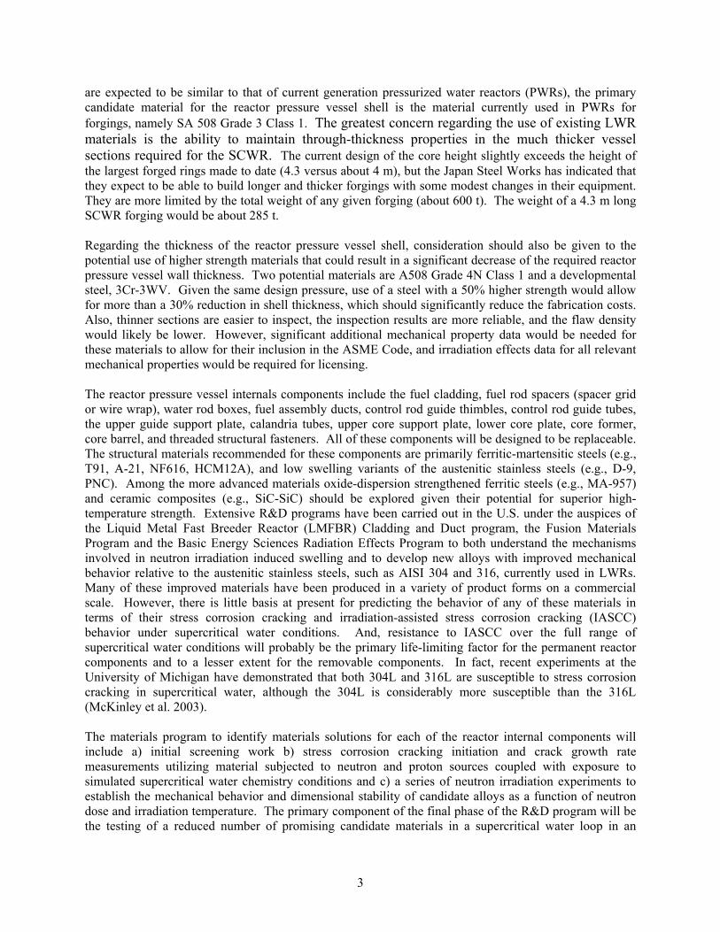
The specific advantages of the SCWR in terms of component types and numbers relative to the PWR and the BWR are summarized in Table I. The SCWR reactor pressure vessel will be similar to a PWR reactor pressure vessel, although thicker. The steam piping will also be thicker. The control rods can be inserted through the reactor pressure vessel upper head. The SCWR containment will be smaller than a BWR containment and much smaller than most PWR containments because of the significantly lower water inventory and the use of suppression pools. Sketches of a SCWR and ABWR containment building are shown in Figure 5. Note that the footprint of the two buildings is about the same, but the overall height and volume of the SCWR containment is reduced by about 40%. Also note that the SCWR generates much more electric power than the ABWR because of the increase in efficiency discussed above. The number of steam lines will also be reduced because of the higher steam density. In summary, the SCWR will be a more compact and simpler plant that, for a given thermal power, generates more electricity, resulting in a reduction of the specific capital cost ($/kWe).
Table I. Comparison of the SCWR, PWR and BWR plants (for given thermal power).
SGs / Steam Separators Pressurizer Recirc.
Pumps
Reactorpressure
vessel
Controlrods Containment Steam
Lines
PWR Yes Yes Yes Small Top Large 4 BWR Yes No Yes Large Bottom Small 4
SCWR No No No Small Top Small 2
Figure 5. Sketches of the SCWR and ABWR containment buildings with overall dimensions provided (from Oka, 2003).
The development of the SCWR concept can build on the successful experience with the supercritical coal-fired boiler, with which it shares a similar power conversion cycle and balance of plant. There are over 460 supercritical coal-fired power plants in operation in the world, of which about 150 are in the U.S. alone, with an installed capacity of over 100,000 MWe (Table III.a), comparable to that of the entire U.S. nuclear industry. The performance of these supercritical fossil units has been quite good (Table III.b), and worldwide the vast majority of coal-fired power plants of recent construction are supercritical water
12
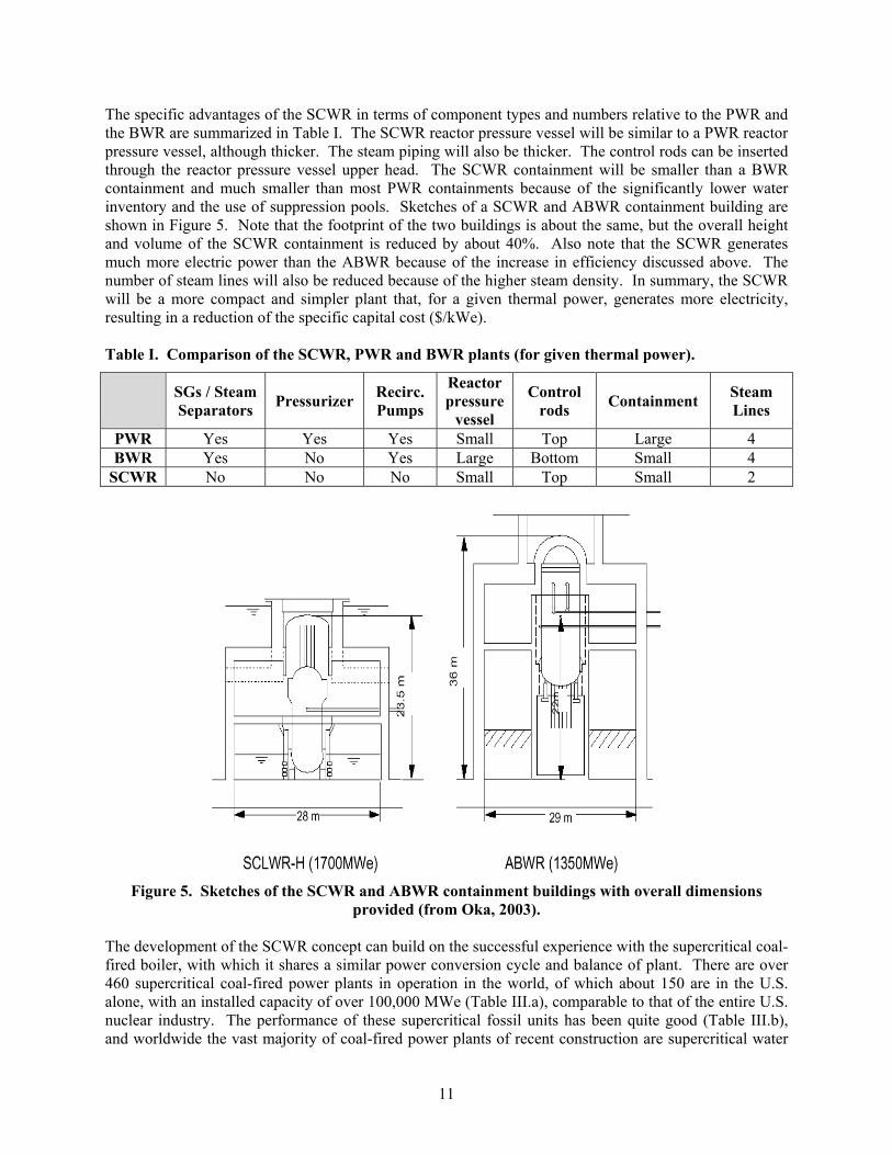
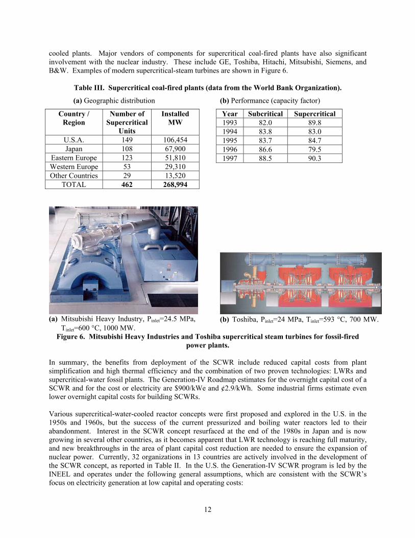
cooled plants. Major vendors of components for supercritical coal-fired plants have also significant involvement with the nuclear industry. These include GE, Toshiba, Hitachi, Mitsubishi, Siemens, and B&W. Examples of modern supercritical-steam turbines are shown in Figure 6.
Table III. Supercritical coal-fired plants (data from the World Bank Organization).
(a) Geographic distribution (b) Performance (capacity factor)
Country / Region
Number of Supercritical
Units
InstalledMW
U.S.A. 149 106,454 Japan 108 67,900
Eastern Europe 123 51,810 Western Europe 53 29,310 Other Countries 29 13,520
TOTAL 462 268,994
Year Subcritical Supercritical 1993 82.0 89.8 1994 83.8 83.0 1995 83.7 84.7 1996 86.6 79.5 1997 88.5 90.3
(a) Mitsubishi Heavy Industry, Pinlet=24.5 MPa, Tinlet=600 C, 1000 MW.
(b) Toshiba, Pinlet=24 MPa, Tinlet=593 C, 700 MW.
Figure 6. Mitsubishi Heavy Industries and Toshiba supercritical steam turbines for fossil-fired power plants.
In summary, the benefits from deployment of the SCWR include reduced capital costs from plant simplification and high thermal efficiency and the combination of two proven technologies: LWRs and supercritical-water fossil plants. The Generation-IV Roadmap estimates for the overnight capital cost of a SCWR and for the cost or electricity are $900/kWe and ¢2.9/kWh. Some industrial firms estimate even lower overnight capital costs for building SCWRs.
Various supercritical-water-cooled reactor concepts were first proposed and explored in the U.S. in the 1950s and 1960s, but the success of the current pressurized and boiling water reactors led to their abandonment. Interest in the SCWR concept resurfaced at the end of the 1980s in Japan and is now growing in several other countries, as it becomes apparent that LWR technology is reaching full maturity, and new breakthroughs in the area of plant capital cost reduction are needed to ensure the expansion of nuclear power. Currently, 32 organizations in 13 countries are actively involved in the development of the SCWR concept, as reported in Table II. In the U.S. the Generation-IV SCWR program is led by the INEEL and operates under the following general assumptions, which are consistent with the SCWR’s focus on electricity generation at low capital and operating costs:
13
Direct cycle, Thermal spectrum, Light-water cooled and moderated, Low-enriched uranium oxide fuel, Base load operation.
Similar assumptions are adopted in other countries with the notable exception of Canada were the focus is on a light-water-cooled, heavy-water-moderated SCWR concept.
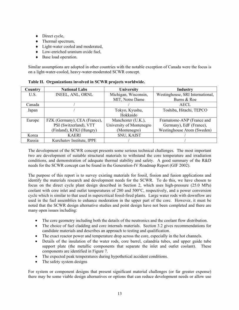
Table II. Organizations involved in SCWR projects worldwide.
Country National Labs University Industry U.S. INEEL, ANL, ORNL Michigan, Wisconsin,
MIT, Notre Dame Westinghouse, SRI International,
Burns & Roe Canada / / AECL Japan / Tokyo, Kyushu,
HokkaidoToshiba, Hitachi, TEPCO
Europe FZK (Germany), CEA (France), PSI (Switzerland), VTT
(Finland), KFKI (Hungry)
Manchester (U.K.), University of Montenegro
(Montenegro)
Framatome-ANP (France and Germany), EdF (France),
Westinghouse Atom (Sweden) Korea KAERI SNU, KAIST / Russia Kurchatov Institute, IPPE / /
The development of the SCWR concept presents some serious technical challenges. The most important two are development of suitable structural materials to withstand the core temperature and irradiation conditions, and demonstration of adequate thermal stability and safety. A good summary of the R&D needs for the SCWR concept can be found in the Generation-IV Roadmap Report (GIF 2002).
The purpose of this report is to survey existing materials for fossil, fission and fusion applications and identify the materials research and development needs for the SCWR. To do this, we have chosen to focus on the direct cycle plant design described in Section 2, which uses high-pressure (25.0 MPa) coolant with core inlet and outlet temperatures of 280 and 500 C, respectively, and a power conversion cycle which is similar to that used in supercritical fossil-fired plants. Large water rods with downflow are used in the fuel assemblies to enhance moderation in the upper part of the core. However, it must be noted that the SCWR design alternative studies and point design have not been completed and there are many open issues including:
The core geometry including both the details of the neutronics and the coolant flow distribution. The choice of fuel cladding and core internals materials. Section 3.2 gives recommendations for candidate materials and describes an approach to testing and qualification. The exact reactor power and temperature drop across the core, especially in the hot channels. Details of the insulation of the water rods, core barrel, calandria tubes, and upper guide tube support plate (the metallic components that separate the inlet and outlet coolant). These components are identified in Figure 7. The expected peak temperatures during hypothetical accident conditions. The safety system designs
For system or component designs that present significant material challenges (or far greater expense) there may be some viable design alternatives or options that can reduce development needs or allow use
14
of available (less expensive) materials. Nevertheless, we were not able to assess those alternatives in the time allotted for this report and, to move forward with this material research and development assessment, the authors of this report felt that it was necessary to identify a plausible design. All of the authors of this report feel comfortable that the design described in Section 2 is a promising design, but none of us believe that it is the final design.
Section 3 is organized by major component and within each major component subsection we discuss:
The status of the existing information The materials selection and development and qualification requirements The regulatory and codification requirements The materials testing and data base requirements The needed manufacturing infrastructure
Section 3.1 discusses water chemistry issues in a SCWR. Section 3.2 addresses the reactor pressure vessel, Section 3.3 covers the reactor internals including both cladding and in-core structural materials as well as support structures, Section 3.4 addresses the pump and piping materials, and Section 3.5 covers the power conversion system including the main steam line piping, turbine, and recuperator.
The needed materials development programs and costs are summarized in Section 4 and compared with historical benchmarks. We conclude that there are significant materials development and qualification needs for the SCWR, but existing materials have been identified that might eventually prove through testing to be able to meet the requirements of all the SCWR components and subsystems. Note that these costs are for “viability” research and development as defined in the Generation IV Roadmap (GIF 2002). Viability research and development examines the feasibility of key technologies and is that R&D necessary for proof of the basic concepts, technologies, and relevant conditions. Potential showstoppers are identified and resolved. The information generated at this stage of the R&D is sufficient for the conceptual design of a prototype. It is not sufficient for the final design of the plant.

15
2. Reactor Description 2.1. REFERENCE DESIGN POWER AND COOLANT CONDITIONS
As mentioned in the introduction, we have chosen to focus on a direct cycle plant design. High-pressure (25.0 MPa) coolant enters the vessel at 280 C. The inlet flow splits with about 70% of the inlet flow going down the space between the core barrel and the reactor pressure vessel (the down-comer) and about 30% of the inlet flow going to the plenum at the top of the rector pressure vessel to then flow downward through the core in special water rods to the inlet plenum. This strategy is employed to provide good moderation at the top of the core. The coolant is heated to about 500 C and delivered to a power conversion cycle which is similar to that used in supercritical fossil-fired plants: high- intermediate- and low-pressure turbines are employed with two re-heaters. The single most significant factor in changing the materials needs in going from the current PWR and BWR designs to the SCWR is the associated increase in outlet coolant temperature from 300 to 500 C.
The reference power, efficiency, pressure, and coolant flow rate and temperatures are listed in Table III. Figure 7 is a sketch of the reactor pressure vessel and internals showing the coolant flow paths.
Table III. U.S. Generation-IV SCWR reference design power and coolant conditions.
Parameter Value Thermal power 3575 MWt Net electric power
1600 MWe
Net thermal efficiency
44.8%
Operating pressure
25 MPa
Reactor inlet temperature
280 C
Reactor outlet temperature
500 C
Reactor flow rate
1843 kg/s
Plant lifetime 60 years
Top of active fuel
Lower core plate
Barrel flange
CR guide tubes
Core
Upper guide support plate
Water rods
Cold nozzle Hot nozzle
Bottom of active fuel
Steam line
Water in at 280 C
Water out at 500 C
Upper core support plate
Calandria tubes
Figure 7. The SCWR RPV
16
2.2. SCWR REACTOR PRESSURE VESSEL
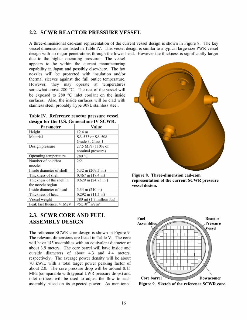
A three-dimensional cad-cam representation of the current vessel design is shown in Figure 8. The key vessel dimensions are listed in Table IV. This vessel design is similar to a typical large-size PWR vessel design with no major penetrations through the lower head. However the thickness is significantly larger due to the higher operating pressure. The vessel appears to be within the current manufacturing capability in Japan and possibly elsewhere. The hot nozzles will be protected with insulation and/or thermal sleeves against the full outlet temperature. However, they may operate at temperatures somewhat above 280 C. The rest of the vessel will be exposed to 280 C inlet coolant on the inside surfaces. Also, the inside surfaces will be clad with stainless steel, probably Type 308L stainless steel.
Table IV. Reference reactor pressure vessel design for the U.S. Generation-IV SCWR.
Parameter Value Height 12.4 m Material SA-533 or SA-508
Grade 3, Class 1 Design pressure 27.5 MPa (110% of
nominal pressure) Operating temperature 280 CNumber of cold/hot nozzles
2/2
Inside diameter of shell 5.32 m (209.5 in.) Thickness of shell 0.467 m (18.4 in) Thickness of the shell in the nozzle region
0.629 m (24.75 in.)
Inside diameter of head 5.34 m (210 in) Thickness of head 0.292 m (11.5 in) Vessel weight 780 mt (1.7 million lbs) Peak fast fluence, >1MeV <5x10¹⁹ n/cm2
2.3. SCWR CORE AND FUEL ASSEMBLY DESIGN
The reference SCWR core design is shown in Figure 9. The relevant dimensions are listed in Table V. The core will have 145 assemblies with an equivalent diameter of about 3.9 meters. The core barrel will have inside and outside diameters of about 4.3 and 4.4 meters, respectively. The average power density will be about 70 kW/L with a total target power peaking factor of about 2.0. The core pressure drop will be around 0.15 MPa (comparable with typical LWR pressure drops) and inlet orifices will be used to adjust the flow to each assembly based on its expected power. As mentioned
Figure 8. Three-dimension cad-com representation of the current SCWR pressure vessel design.
Downcomer
Fuel Assemblies
Core barrel
Reactor Pressure Vessel
Figure 9. Sketch of the reference SCWR core.

17
above, about 30% of the inlet flow will be passed through the water rods with a flow rate in the water rods of about 554 kg/s.
Table V. Reference reactor core design for the U.S. Generation-IV SCWR.Parameter Value
Number of fuel assemblies 145 Equivalent diameter 3.93 m Core barrel inside and outside diameter 4.3/4.4 m Axial/Radial/Local/Total Peaking Factor 1.4/1.3/1.1/2.0 (best estimate)
1.4/1.4/1.2/2.35 (safety analysis) Average power density 69.4 kW/L Average linear power 19.2 kW/m Peak linear power at steady-state conditions 39 kW/m Core pressure drop 0.15 MPa Water rod flow 554 kg/s (30% of nominal flow rate)
The reference SCWR fuel assembly design is shown in Figure 10 and the relevant dimensions are listed in Table VI. Our analyses have shown that it may be necessary to insulate the water moderator boxes to retain a sufficient moderator density. Figure 11 is a 1/8 size scaled drawing of a SCWR fuel assembly with Zircaloy water boxes with 1 mm of yttrium-stabilized zirconium oxide on the outside of the water boxes (i.e. on the hot coolant side of the water boxes). Figure 10 shows typical Westinghouse PWR size control rods inside 16 water moderator boxes (not shown are the Zircaloy control rod guide tubes). However, our control rod worth calculations are not complete and it may be desirable change the number and/or size of the control elements, or it may be desirable to change the locations of the control elements. Also, it is assumed that there will be one instrumentation tube in each assembly at the center fuel rod location, but maybe more will be needed. Also, a number of the dimensions are tentative including the fuel bundle wall thickness and the inter-assembly gap size and the fuel pin spacer have yet to be designed. In fact, we may need to use wire wrap spacers because of the tight dimensions between the fuel rods. However, we need to determine whether hot spots will occur under the wires in a supercritical water environment.
Figure 10. The SCWR fuel assembly with metal water rod boxes.
Figure 11. The SCWR fuel assembly with zirconium oxide insulated water rod boxes.
Water rod box and channel insulation
Fuel rods

18
Table VI. Reference fuel assembly design for the U.S. Generation-IV SCWR.Parameter Value
Fuel pin lattice Square 25x25 array Number of fuel pins per assembly 300 Number of water rods per assembly 36 Water rod side 33.6 mm Water rod wall thickness 0.4 mm (plus insulation if needed)Water rod wall materials TBD Number of instrumentation rods per assembly 1 Number of control rod fingers per assembly 16 Control rod material B4C for scram, Ag-In-Cd for control Number of spacer grids 14 (preliminary estimate) Assembly wall thickness 3 mm (plus insulation if needed)Assembly wall material TBD Assembly side 286 mm Inter-assembly gap 2 mm Assembly pitch 288 mm
The reference fuel pin dimensions are listed in Table VII. With the exception of the plenum length and fill pressure, the fuel pin dimensions are typical of 17 by 17 PWR fuel assembly pins. However, the fuel pin pitch is considerably smaller than the pitch used in LWRs. The U-235 enrichment, the Gd2O3 loading and fuel burnup are typical of the values used in high burnup LWR fuel.
Table VII. Reference fuel pin design for the U.S. Generation-IV SCWR.Parameter Value
Fuel pin outside diameter 10.2 mm Fuel pin pitch 11.2 mm Cladding thickness 0.63 mm Cladding materials TBD Fuel pellet outside diameter 8.78 mm Fuel composition UO2, 95% TD Fuel enrichment 5% wt. average Target average burnup at discharge 45,000 MWD/t or higher Burnable poisons Gd2O3 (Distribution TBD) Heated length 4.27 m Fission gas plenum length 0.6 m Total fuel pin height 4.87 m Fill gas pressure at room temperature 6.0 MPa
2.4. REACTOR PRESSURE VESSEL INTERNALS
The important reactor pressure vessel internals include the lower core support plate, the core former, the core barrel, the upper core support plate, the calandria tubes located immediately above the upper core support plate, the upper guide support plate, the hot nozzle thermal sleeve or insulation, and the control rod guide tubes. The location and approximate shape of most of these components is shown in Figure 7. All the reactor pressure vessel internals components will be designed for periodic replacement so that high fluence (>20 dpa) loadings will not need to be considered.

19
Some of these components, including the lower core support plate and the control rod guide tubes in the upper head, will be subjected to normal PWR coolant temperature conditions and will be similar to the components typically used in PWRs. However, a number of the reactor pressure vessel internals, including the core barrel (or possibly the core former, depending on the design details), the upper guide support plate, the calandria tubes, and the reactor pressure vessel hot nozzle sleeve, will be in contact with the inlet temperature at 280 C on one side and the hot outlet coolant at a temperature of 500 C on the other side. Our preliminary stress analyses indicate that we will not be able to use metal wall designs that are similar to those currently used in LWRs for those components. Such a high temperature drop across those walls will cause the thermal stresses and deformations to be too large and/or cause too much heat to be transferred across the walls. For example, a simplified thermal stress analysis of the upper guide support plate was performed using a temperature difference of 220 °C (396 °F) and the Pro/Mechanica software. The result was that much of the structure will exceed the 3 Sm Primary + Secondary stress limit of Subsection NG of the ASME code as shown in Figure 12. Resolution of these issues may require new design features including special materials, insulation layers, and/or use of an insulating layer between double walls. Some other reactor pressure vessel internals components, such as the upper core support plate, will be exposed to the outlet coolant at a temperature of about 500 C on all sides. Materials
recommendations for these components, as well as for the removable components of the core, are discussed in Section 3.2.
The size and shape of most of the reactor pressure vessel internals discussed above should be similar to comparable components in a large Westinghouse designed PWR. However, it should be noted that the design of the calandria tubes that guide the flow of the moderator water through the hot region above the core and guide the control rods is not complete. We need to minimize the heat transfer surface area, one way to do that is to combine the outside water moderator boxes into one channel in the region above the core.
2.5. CONTAINMENT DESIGN
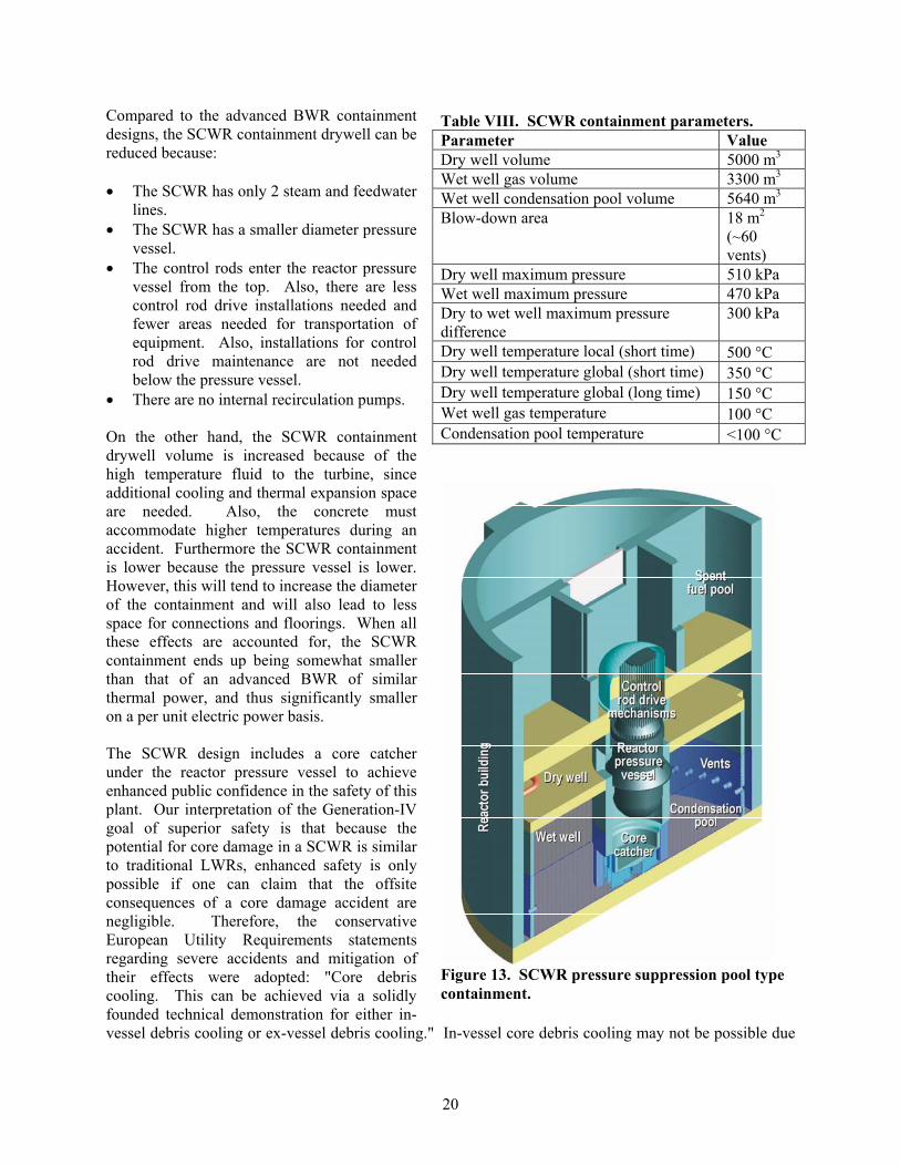
The SCWR containment will be a pressure-suppression type containment with a condensation pool (essentially the same design as modern BWRs). The key containment parameters are listed in Table VIII. A 3-dimensional isometric sketch of the SCWR containment is shown in Figure 13 and an axial view with dimensions is shown in Figure 14. The dry and wet well volumes were calculated to limit the pressure build-up to typical BWR levels following a LOCA or a severe accident with core melting (hydrogen generation is considered). The condensation pool water inventory provides ample margin for residual heat removal and meets the requirement that active safety systems are not needed during the first 24 hours following an initiating event resulting in a severe accident. The blow-down pipes or vents are placed in the outer cylindrical walls due to lack of space in the inner cylindrical walls.
Figure 12. Results of the preliminary thermal stress analysis of the upper guide support plate.
20
Compared to the advanced BWR containment designs, the SCWR containment drywell can be reduced because:
The SCWR has only 2 steam and feedwater lines.The SCWR has a smaller diameter pressure vessel.The control rods enter the reactor pressure vessel from the top. Also, there are less control rod drive installations needed and fewer areas needed for transportation of equipment. Also, installations for control rod drive maintenance are not needed below the pressure vessel. There are no internal recirculation pumps.
On the other hand, the SCWR containment drywell volume is increased because of the high temperature fluid to the turbine, since additional cooling and thermal expansion space are needed. Also, the concrete must accommodate higher temperatures during an accident. Furthermore the SCWR containment is lower because the pressure vessel is lower. However, this will tend to increase the diameter of the containment and will also lead to less space for connections and floorings. When all these effects are accounted for, the SCWR containment ends up being somewhat smaller than that of an advanced BWR of similar thermal power, and thus significantly smaller on a per unit electric power basis.
The SCWR design includes a core catcher under the reactor pressure vessel to achieve enhanced public confidence in the safety of this plant. Our interpretation of the Generation-IV goal of superior safety is that because the potential for core damage in a SCWR is similar to traditional LWRs, enhanced safety is only possible if one can claim that the offsite consequences of a core damage accident are negligible. Therefore, the conservative European Utility Requirements statements regarding severe accidents and mitigation of their effects were adopted: "Core debris cooling. This can be achieved via a solidly founded technical demonstration for either in-vessel debris cooling or ex-vessel debris cooling." In-vessel core debris cooling may not be possible due
Table VIII. SCWR containment parameters. Parameter Value Dry well volume 5000 m3
Wet well gas volume 3300 m3
Wet well condensation pool volume 5640 m3
Blow-down area 18 m2
(~60vents)
Dry well maximum pressure 510 kPa Wet well maximum pressure 470 kPa Dry to wet well maximum pressure difference
300 kPa
Dry well temperature local (short time) 500 CDry well temperature global (short time) 350 CDry well temperature global (long time) 150 CWet well gas temperature 100 CCondensation pool temperature <100 C
Figure 13. SCWR pressure suppression pool type containment.

21
to the high power and small vessel of the SCWR. Therefore, a core catcher was designed that would prevent contact between any core debris and the containment boundary. In other words, in accordance with the principle of defense in depth we have designed three barriers into the system: in-vessel retention, ex-vessel retention in a core catcher, and finally the containment basemat. Note that the core catcher is low enough that it can be flooded during any accident and assure passive ex-vessel cooling of the debris.
Figure 14. SCWR pressure suppression containment building.
2.6. POWER CONVERSION CYCLE
The reference SCWR system will have a power conversion cycle that is very similar to a supercritical coal-fired plant, with the boiler replaced by the nuclear reactor. As part of the U.S. Gen-IV SCWR R&D program, Burns & Roe Enterprises Inc. has performed a conceptual study of the power conversion cycle for the SCWR to identify an optimal configuration that will maximize the thermal efficiency and
22
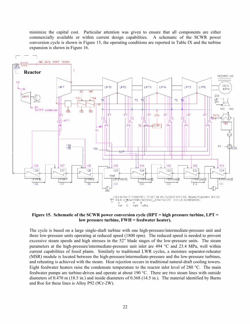
minimize the capital cost. Particular attention was given to ensure that all components are either commercially available or within current design capabilities. A schematic of the SCWR power conversion cycle is shown in Figure 15, the operating conditions are reported in Table IX and the turbine expansion is shown in Figure 16.
Figure 15. Schematic of the SCWR power conversion cycle (HPT = high pressure turbine, LPT = low pressure turbine, FWH = feedwater heater).
The cycle is based on a large single-shaft turbine with one high-pressure/intermediate-pressure unit and three low-pressure units operating at reduced speed (1800 rpm). The reduced speed is needed to prevent excessive steam speeds and high stresses in the 52” blade stages of the low-pressure units. The steam parameters at the high-pressure/intermediate-pressure unit inlet are 494 C and 23.4 MPa, well within current capabilities of fossil plants. Similarly to traditional LWR cycles, a moisture separator-reheater (MSR) module is located between the high-pressure/intermediate-pressure and the low-pressure turbines, and reheating is achieved with the steam. Heat rejection occurs in traditional natural-draft cooling towers. Eight feedwater heaters raise the condensate temperature to the reactor inlet level of 280 C. The main feedwater pumps are turbine-driven and operate at about 190 C. There are two steam lines with outside diameters of 0.470 m (18.5 in.) and inside diameters of 0.368 (14.5 in.). The material identified by Burns and Roe for these lines is Alloy P92 (9Cr-2W).
Reactor

23
Table IX. List of pressures, temperatures, mass flow, and enthalpy at the numbered locations of Figure 15.
Stream p [bar] T [C] T [kg/s] h [kJ/kg]1 Throttle or initial condition outside ST 235 494 1722.47 3167.36 PIPT ahead of intercept valve 12 188 1130.63 2773.711 Condenser (LPT exhaust 0.05 33.1 782.36 2290.312 SSR Inlet 1.24 105.8 0.94 2616.514 After 2nd RH 12 363 149.69 3182.215 LPT Crossover 12 363 982.07 3182.240 Inlet stream of FPT 11.43 361.4 96.15 3179.960 Extr1 (or exh if only 1 group) of FPT 0.07 38.7 96.15 2410.462 Add / extr of ST group 2 70 313.3 265.4 289364 Add / extr of ST group 4 45 259.4 127.38 2805.365 Add / extr of ST group 5 23 219.6 75.74 2684.867 Add / extr of ST group 7 5.4 264.2 13.39 2989.368 Add / extr of ST group 8 2.5 179.2 6.82 2825.170 Add / extr of ST group 10 0.6 86 9.84 2585.172 Add / extr of ST group 12 0.13 51.1 3.33 2382.173 Add / extr of ST group 13 0.05 33.1 130.3 2290.382 Stream to GSC 0.83 0.83 N/A 0.38 2616.5101 Heating steam at FWH1 0.12 49.5 19.96 2379.8102 Heating steam at FWH2 0.58 85 59.06 2582.7103 Heating steam at FWH3 2.4 177.8 40.94 2822.8104 Heating steam at FWH4 5.18 262.8 80.32 2987105 Heating steam at FWH5 11.08 361.1 53.54 3179.9106 Heating steam at FWH6 22.05 217.4 75.74 2682.4107 Heating steam at FWH7 42.17 254.5 127.38 2803108 Heating steam at FWH8 67.11 309.6 157.45 2890.7111 Drain liquid at FWH1 0.12 49.5 200.94 207.3112 Drain liquid at FWH2 0.58 52.9 180.99 221.5113 Drain liquid at FWH3 2.4 87.8 121.93 367.7114 Drain liquid at FWH4 5.18 112 80.99 470.2115 Drain liquid at FWH5 11.08 184.4 1842.92 782.5116 Drain liquid at FWH6 22.05 195.6 588.98 832.7117 Drain liquid at FWH7 42.17 220 513.24 944118 Drain liquid at FWH8 67.11 256.3 385.86 1116.4121 Feedwater into FWH1 19.42 34.2 878.88 145122 Feedwater into FWH2 17.81 47.3 1079.83 199.6123 Feedwater into FWH3 15.55 82.2 1079.83 345.2124 Feedwater into FWH4 14.69 106.1 1079.83 446125 Feedwater into FWH5 11.08 150.5 1079.83 634.5126 Feedwater into FWH6 253.69 190 1842.92 819.2127 Feedwater into FWH7 253.13 214.4 1842.92 926.2128 Feedwater into FWH8 252.53 250.7 1842.92 1090.8142 Feed water leaving condenser 0.35 33.1 782.74 138.8143 Cooling water into condenser 3.74 17.7 30275.3 74.5144 Cooling water leaving condenser 2.51 31 30275.3 130.1145 Feed water into reactor 252.01 280 1842.92 1230146 Steam leaving reactor 246.75 499.7 1842.92 3169.6152 Heating steam of 1st RH 70 313.3 107.95 2893153 Drain of 1st RH N/A N/A 107.95 825.7154 Heating steam of 2nd RH 246.75 499.7 120.46 3169.6155 Drain of 2nd RH N/A N/A 120.46 1188.2156 Moisture separator drain N/A N/A 120.57 798.4201 Cooling tower inlet air N/A 20 32549.72 N/A204 Cooling tower exit air N/A 27.2 33201.16 N/A210 SSR to condenser 1.24 105.8 0.94 2616.5Valve Stem leak 1 => LPcrs N/A N/A 1.13 3167.3Valve Stem leak 2 => SSR N/A N/A 0.05 3167.3HPT LP leak 1 => FWH4 N/A N/A 0.67 2583.4HPT LP leak 2 => SSR N/A N/A 0.89 2583.4
24
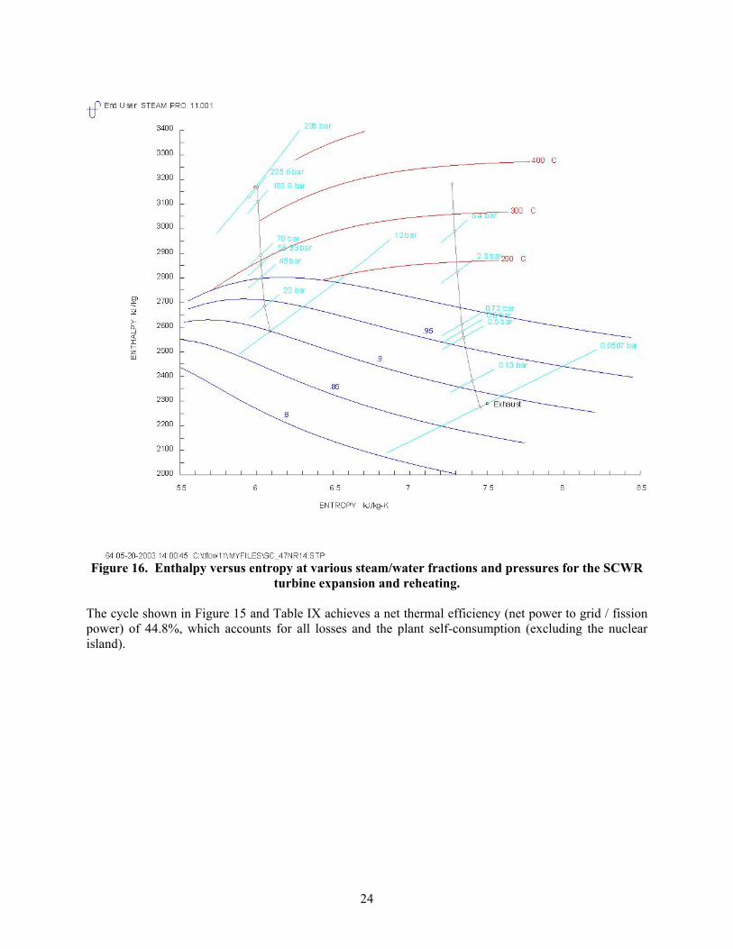
Figure 16. Enthalpy versus entropy at various steam/water fractions and pressures for the SCWR turbine expansion and reheating.
The cycle shown in Figure 15 and Table IX achieves a net thermal efficiency (net power to grid / fission power) of 44.8%, which accounts for all losses and the plant self-consumption (excluding the nuclear island).

25
3. SCWR Reactor System Materials Data Needs
3.1. SUPERCRITICAL WATER CHEMISTRY AND CORROSION ISSUES
3.1.1. Supercritical Fossil Plant Water Quality Control
In fossil-fired steam generators, the large surface area of low-alloy steel tubes used in the evaporator sections is protected from corrosion by the development and maintenance of a protective oxide film of magnetite (Fe3O4). Penetration of this film can lead to rapid localized corrosion by contaminants in the water, as well as by local concentrations of water treatment chemicals. The purpose of boiler feedwater conditioning and the use of water treatment chemicals is to maintain an environment conducive to the formation, maintenance, and repair of the protective magnetite film, as well as to neutralize possible acidic conditions that may occur on surfaces exposed to the first condensing moisture droplets. A large fraction of the forced outages experienced by fossil plants is caused by corrosion-related problems in the water-steam circuit. The types of boiler tube failures experienced, their root causes, and preventative measures have been compiled in an EPRI report by Dooley and McNaughton (1996).
Very stringent specifications are applied for control of the quality of the water used in fossil-fired power plants. These are aimed at:
• Prevention of corrosion of all the components that are in contact with water over the range of temperatures and pressures encountered;
• Minimizing transportation of any corrosion products (mainly magnetite, Fe3O4) that do form, for instance, by corrosion of the condenser and feedwater heaters, to the heat absorption surfaces where they can deposit and rapidly reduce the thermal conductivity of the tubes and lead to tube overheating; and
• Prevent deposition and corrosion in the turbine by ensuring that the concentration of all impurities in the feed-water is lower than their solubility limits in the high-pressure steam to avoid their condensation in the turbine.
As a result, the challenge posed in the control of the water condition (‘cycle chemistry’) is one of balancing the requirements for minimizing corrosion and corrosion product deposition in the heat absorption part of the circuit, while limiting the carryover in the steam of salts likely to pose problems in the turbine. In addition to corrosion products from components and piping materials due to their solubility in high-pressure water, from localized corrosion, or erosion, additional sources of depositing materials can enter the fossil-fired steam generator from in-leakage in the condenser, from the feed water itself, and from the water treatment chemicals.
In once-through fossil-fired units (the circuit does not include a steam-separation drum) of the type considered in the SCWR, the quality of the water is controlled by treatment of the feedwater. In the U.S., two major approaches are used:
(i) The all-volatile treatment (AVT), which is based on measures to practically eliminate oxygen from the system to prevent corrosion. In this treatment the pH is adjusted (ammonia) to 9.2-9.6 for all-ferrous systems (8.8-9.1 for mixed ferrous-copper systems), and the oxygen content of the water is controlled to < 5 ppb (cation conductivity is in the range 0.2-0.4 µS cm-1). This is accomplished by de-oxygenation in the condenser and deaerator, followed by the addition of oxygen-scavenging chemicals such as hydrazine. A problem with this approach is that the normally protective oxide formed on ferrous alloys is unstable in the feedwater train, leading to

26
dissolution and transport of corrosion products, as well as erosion-corrosion attack of the economizer inlet tubes.
(ii) Oxygenated treatment (OT; used only for all-ferrous systems), in which the pH is adjusted (ammonia) to 8.0-8.5 and then, following purification in the condenser, demineralizer/condensate polisher, and deaerator (to < 0.2 µS cm-1), oxygen is added to the level of 30-150 ppb. The resulting high-purity water minimizes corrosion of the feedwater train up to the economizer inlet. The controlled, but limited oxygen content promotes the formation of a more protective layer of Fe3O4, in which the pores are blocked by FeOOH; this modified magnetite layer also has a lower solubility than magnetite in the feedwater. Adoption of oxygenated water treatment has resulted in a significant reduction of water-steam-side corrosion-related problems in fossil-fired units.
The water chemistry guidelines for AVT, OT and for LWRs are compared in Table X. Guidelines for determining the most appropriate water treatment system for a given plant configuration are available in a series of reports published by EPRI.
Table X. Typical primary water chemistry of supercritical fossil plants and LWRs.
Items Fossil AVTa
FossilAVTb
Fossil OT BWRc,d PWRc,d,e SCWR
Pressure, MPa 25-30 25-30 25-30 6.9 15.5 25 Inlet temp. °C 280 280 280 278 286 280 Outlet temp. °C 540-600 540-600 540-600 285 324 500 Conductivity (inlet) S cm-1 <0.2 <0.2 <0.15 <0.2f, <0.1g 1-40f ?Oxygen, ppb 1-10 <5 30-150 20-200g <5f ?Hydrogen, ml/kg (STP) na na na 0-50g 25–50f,h ? LiOH, ppm dc dc dc dc 0.6–4f dcBoron, ppm dc dc dc dc 0–4000f dcCl-, ppm na na na <0.02f <0.15f ?F-, ppm na na na <0.1 <0.15f ?Fe, ppb <5 <10 <5 <1.0-2.5g na ? Cu, ppb <2 <2 na <10f, <0.1-0.3g na ? Silica, ppb <20 <20 na <100f <200f ?pH (room temperature) 9.2-9.6 8.8-9.1 8.0-8.5 6.1–8.1f 6.9–7.4f ?a plants with all ferrous condenser/feedwater system b plants with mixed metallurgyc P. M. Scott 1998. d Lin 1996. e IAEA 1997.
f In the reactor water. g In the feedwater. h EPRI recommends use of the lower number. dc = not applicable because of the direct cycle. na = not available
3.1.2. LWR Water Quality Control
Control of the water chemistry has been critical to the continued operations of LWRs. The BWR would normally operate with an oxygen overpressure for three reasons: first, the system is a direct cycle so is more susceptible to air infiltration; second, hydrogen leaks out of the system easier via diffusion into and out of materials; third, radiolysis also results in a series of other products that are highly oxidizing, for example, hydrogen peroxide. Moreover, the BWR environment is also slightly acidic because air carries CO2, which leads to formation of carbonic acid. The result is a rather aggressive environment, which could cause excessive corrosion of the reactor materials. In BWRs the general expectation is that the propensity for SCC will increase with increasing oxygen content, and hydrogen is generally added to the feedwater to recombine with oxygen and suppress the corrosion potential below the threshold for SCC, which is -0.230 V (SHE) [Cowan 1996, Pocock 1986]. However, it takes a significant hydrogen
27
overpressure to induce recombination of oxygen with hydrogen, and this also causes higher nitrogen-16 radiation level in the steam lines [Lin 2000]. (When hydrogen chemistry is used the nitrogen-16 release is higher because the nitrogen species are more volatile.) In recent years thin layers of noble metals (i.e., platinum and rhodium) have been deposited on the surface of BWR structural materials to suppress the corrosion potential even at relatively low hydrogen injection levels [Hettiarachchi et al. 1999]. On the other hand, the PWR is an indirect cycle, less susceptible to air infiltration. However, an oxygen overpressure would be present in PWRs as well due to diffusion of radiolytic hydrogen out of the system. Therefore, hydrogen is also injected in the primary coolant of PWRs, but at somewhat lower rates than in BWRs. Also, a minimum high temperature (about 300 C) pH of 6.9 is required to avoid heavy crud deposits on the fuel rods and boron must be added to the coolant in the form of boric acid as a neutron absorber for reactivity control. Therefore, to counter the effect of the boric acid on the pH, lithium hydroxide is dissolved into the PWR primary water.
3.1.2. Water Chemistry and Corrosion Issues in SCWRs
The impact of the chemistry of supercritical water in the presence of radiation on reactor operations is unknown at this time. While the impact of the SCWR water chemistry will be most important in-vessel, it is possible, dependent on design, that there will be spillover effects on the power conversion systems for which water chemistry control is also very important (See Section 3.5). This section attempts to outline potential issues that may need to be addressed. There is no corresponding section on specific corrosion materials R&D tasks and funding needs in Section 4 of this report, since these corrosion considerations are quite pervasive across multiple components. In lieu of that, the R&D to address the various corrosion issues has been incorporated into the overall R&D described for each component, as needed.
The mechanisms for environmentally sensitive cracking in water-cooled reactors that have been observed include intergranular stress corrosion cracking (IGCC), irradiation-assisted stress corrosion cracking (IASCC), and corrosion fatigue. These mechanisms are affect by several variables including (Hannien and Aho-Mantila 1998, European Commission 1997):
Metallurgical structure, including the presence of M23C6 phases, phase morphology, and depletion of the Cr in zones adjacent to grain boundaries; Irradiation effects on grain boundary impurity segregation; and The aqueous environment, especially the presence of oxidizers and reducers.
In the case of IASCC of austenitic stainless steels, an additional parameter is a fluence threshold that is approximately equivalent to 1 displacement per atom (dpa). Further, nickel-base super alloys are sensitive to the presence of impurities including phosphorous, silicon, boron, and sulfur.
While materials have been identified that function in LWRs, the performance of these same materials in a SCWR is uncertain and will be dependent on the environment of the SCWR. In this respect, while operating temperatures have been proposed, the water chemistry is ill defined.
There are several aspects of the water chemistry of the SCWR that will impact the corrosion behavior of materials of construction. The concentrations of the transient and stable species due to radiolysis of the water at the higher operating temperature (as compared to LWRs) may well be significantly different. The chemical potential of oxygen and hydrogen peroxide, which will be significantly different in the supercritical fluid, will affect the corrosion potential of the water. This in turn determines whether magnetite (Fe3O4) or hematite (Fe2O3) forms and the morphology of these films, which are important to corrosion control on low alloy steels, heat affected zones, etc. Note that the low alloy pressure vessel
28
steel will generally not be exposed to an aqueous environment due to the stainless steel weld overlay cladding, however, possible contact of the pressure vessel steel with the supercritical water will need to be quantified in the safety assessment (Scott 1998).
The chemical potential of the hydrogen should change as much as the chemical potential of the oxygen and hydrogen water chemistry may be just as effective in reducing the oxygen content. However, Bartels et. al (2003) have observed a decrease in the critical reaction rate of the OH radical with hydrogen above 300 °C. Because the radiolysis in the core is kinetically controlled, it might require much more hydrogen to suppress the oxygen and peroxide generation. If too much is required, metal hydriding could occur. The trade-off between these effects, will, to a large extent, determine how much of the LWR and fossil plant water chemistry control experience is applicable to the SCWR.
The control of pH, while theoretically possible, may be difficult in practice, especially in the 300 to 500 °C temperature range. The pH of the water is important in setting the corrosion potential and rate, and to some extent, the mode of corrosion. A range of pH has been successfully employed in LWRs, and this approach will need to be explored.
3.2. REACTOR PRESSURE VESSEL
3.2.1. Status
The reactor pressure vessel (RPV) for the high-power (1600-MWe) SCWR is illustrated in Figures 7 and 8 with various dimensions given in Table IV. The current design provides for a vessel with an inner diameter of 5.322 m (17.46 ft), an outer diameter of 6.256 m (20.52 ft), an overall height of 12.40 m (40.7 ft), and a shell thickness of 467 mm (18.4 in). As shown in the schematic diagram of Figure 8, the nozzle course will be thicker than the shell, but the exact thickness is not yet available; however, light-water reactor experience would result in a nozzle course forging of about 30% greater than the shell. The RPV includes two inlet (cold) nozzles and two outlet (hot) nozzles. The operating pressure is 25 MPa (3628 psi) at a temperature of 280 ºC, with a design pressure of 27.5MPa (3991 psi); presumably, the design temperature is the same as for current LWRs, 343 ºC (650 ºF). To ensure vessel operation at 280 ºC, the design must include a feature to insulate the outlet nozzle from the outlet coolant temperature of 500 ºC. The inner surface of the vessel will be exposed to water at 280 ºC thus would be clad with a weld overlay of Type 308 stainless steel and the outer surface will be insulated, most likely in a manner similar to existing PWRs. Given the operating temperature of 280 ºC and an expected irradiation exposure similar to that of current generation pressurized water reactors (PWR), the primary candidate materials for the RPV shell are those currently used in PWRs, namely SA 508 Grade 3 Class 1 forging (formerly designated SA 508 Class 3) or SA 533 Grade B Class 1 plate. The RPV thickness given above assumes one of those materials. Of those two materials, which have similar chemical compositions and the same design stress intensities in the ASME Code, the SA 508 Grade 3 Class 1 forging is preferred to eliminate the need for axial welds. It is also desirable to fabricate a forging of sufficient height to keep circumferential welds outside the region adjacent to the reactor core (the so-called beltline region). The active height of the current reference core design is ~ 4.3 m (14 ft) (note that the overall fuel assembly height will depend on several design details) and preliminary information from the Japan Steel Works indicates that it will probably be possible to fabricate a 4 to 5 m forging with the radial dimensions listed in Table IV. Figure 17 is a photograph of one of the ABWR beltline forgings being fabricated in Japan with an outside diameter of about 7.5 m and a height of about 4 m.

29
Figure 17. ABWR reactor pressure vessel beltline forging, weight: 127 tons; dimensions: 7.48 m outside diameter, by 7.12 m inside diameter, by 3.96 m high; material: ASME SA 508, Class 3 EQ.
If the RPV design cannot include an insulated outlet nozzle, then more highly alloyed steel must be considered for the shell material to accommodate the higher operating temperature of 500 ºC. In this case, a Cr-Mo steel, such as an advanced 9Cr-1 Mo-V (e.g., Grade 91), would be required. However, for the purpose of this current plan, it is assumed that an insulated nozzle will be accommodated in the design. Additionally, given the shell thickness required for the use of SA 508 Grade 3 Class 1 steel, consideration should be given to the use of alloys of higher strength that would allow for a thinner vessel.
3.2.2. Materials Selection and Development and Qualification Requirements
3.2.2.1. Considerations for a SCWR RPV Design with an Insulated Nozzle
As mentioned above, the materials selection for the RPV shell, head, and cladding are based on current LWR technology with the assumption of an outlet nozzle design that incorporates either insulation or a thermal sleeve to protect the vessel shell against the 500 ºC outlet temperature. Moreover, although precise neutronics and total neutron exposure are not yet available, the material choices are based on the assumption that total irradiation exposure will be no greater than that in current generation PWRs.
The knowledge gained over the past few decades regarding the radiation embrittlement of current LWR materials must be utilized in the preparation of the material specifications for the RPV materials. For example, minimization of sensitizing elements such as copper and phosphorus is critical for mitigation of embrittlement and undesirable segregation, while the nickel content should be kept relatively low yet high enough to maintain the strength and fracture toughness of the A508 Grade 3 Class 1 steel. In this regard, the thickness of the SCWR vessel shell and nozzle course forgings may present difficulties. Therefore, special attention must be paid to the chemical composition and heat treatment specifications to allow for through-thickness hardening to maintain the necessary strength and fracture toughness, yet to also ensure minimization of radiation embrittlement sensitivity.
Also, the design life of sixty years compels consideration of potential thermal aging effects, even though the nominal operating temperature is relatively low. There is no experience to date with the combination
30
of irradiation and thermal aging effects on these steels for such long times (although by the time a SCWR is built information from extended life LWRs may be available). There are thermal aging data on similar steels, however, that indicate increasing thermal embrittlement at the RPV design temperature. As mentioned in Section 2.2, the outlet nozzles, even though insulated, may operate at a nominal temperature somewhat higher than 280 ºC; thus, although the outlet nozzles will not be exposed to significant levels of irradiation, the actual exposure temperature is important for long time operation. The current design temperature for LWR RPVs is 343 ºC (650 ºF); at this time, that temperature is considered to be the maximum temperature to which the RPV should be exposed during operation. This, then, would also be the maximum temperature for the hot nozzle.
Additionally, the reactor vessel should be designed to accommodate a material surveillance program that would include exposure of the shell and nozzle materials to accelerated radiation damage at the temperatures of operation. The surveillance program must meet the requirements of 10CFR50, Appendix H to satisfy regulatory requirements, but a more extensive program is recommended for the first SCWR because it will be a demonstration system and valuable information can be gleaned from the surveillance exposures regarding material performance in a typical operating environment. Thus, the surveillance program is envisioned to include tensile, Charpy impact, and fracture toughness specimens of each material in the RPV, as well as specimens for monitoring and evaluating corrosion and stress corrosion cracking.
Similar to the RPV shell, the RPV bolted closure head and welded bottom head will operate at 280 ºC and the materials of construction will be similar. The materials and fabrication of the heads, including the control rod drive mechanism housings, head bolts, etc. will incorporate the latest materials of choice for current LWRs and currently designed advanced LWRs. Information regarding RPV supports is not yet available and the choice of materials will depend upon the specific design. Similarly, because of uncertainties regarding specific design aspects of the outlet nozzle and the choice of steam line piping, items such as nozzle safe ends cannot yet be fully addressed. There has been a history of cracking in boiling water reactor vessel nozzle and attachment welds, normally due to a combination of residual and applied stresses, a high electrochemical potential of the coolant, and the use of relatively sensitive weld metal such as Alloy 182. A change to a more corrosion resistant weld metal such as Alloy 82, along with specific water chemistry controls, have been instituted as a mitigation measure. For the SCWR, the feedwater line piping will operate at about the same temperature as that for current LWRs, but the uncertainties regarding water chemistry preclude the choice of material for that piping system at this time. The steam line piping, moreover, will operate at about 500 ºC in the region of the nozzle outlet. The issues of piping are discussed in more detail in Section 3.4. Thus, the choice of the piping materials will drive the choice of safe end materials as well as the weld metals used to join them to the piping. The safe end materials could range from carbon steels, to low alloy steels such as certain Cr-Mo varieties, and to stainless steels, including the use of nickel-base materials especially for joining purposes.
As stated earlier, it is anticipated that type 308 stainless steel weld overlay cladding will be appropriate for the current SCWR design. The most common cladding procedure is application of a strip type clad by submerged-arc welding. Although the operating temperature of the water is similar to that in current LWRs, the water chemistry is as yet unknown (see Section 3.1). Thus, the clad material should be included in the qualification experiments and in the surveillance program.
3.2.2.2. Material Considerations for a SCWR RPV Design with an Uninsulated Nozzle
If the design cannot incorporate an insulated nozzle, the material choices for the RPV shell, heads, and nozzles must be different than those discussed above because part of the vessel would operate at 500 ºC. In this case, the design feasibility of a separate nozzle course insulated from the lower shell course and bolted head should be determined. If such a configuration is not feasible, then, as mentioned earlier, the
31
use of a Cr-Mo alloy that maintains strength to higher temperatures would be required for the RPV. A vast amount of experience exists in the non-nuclear industry for long-time operation in this higher temperature range for 2 1/4Cr-1Mo steel, some experience with 3Cr-1Mo, and less with 9Cr-1Mo. An exacerbating issue in this case is that the portion of the vessel shell exposed to significant irradiation may operate at temperatures from 280 to 500 ºC, depending on the specific design. Thus, if the current design changes to incorporate an integral nozzle, the issues regarding the RPV would be different and more uncertain relative to material behavior, and would likely require significantly more development and qualification efforts than associated with the current insulated nozzle design. However, as stated earlier, for the purpose of this current plan, it is assumed that an insulated nozzle will be accommodated in the design.
3.2.2.3. Consideration of Higher Strength Steels
Regarding the thickness of the RPV shell, consideration should be given to the potential use of higher strength materials that could result in a significant decrease of the required reactor pressure vessel wall thickness. There are a number of advantages that would accrue with a steel of significantly higher strength:
(1) Given the same design pressure, use of a steel with a 50% higher strength would allow for more than a 30% reduction in shell thickness;
(2) Thinner sections allow smaller ingots to be cast;(3) Thinner plates or forgings ensure more uniform compositions and properties in the final product
after heat treatment and hot-rolling or forging; (4) Given the capacity, even larger-height forgings can be fabricated; (5) Heat treatment of thinner sections is easier (more economical), and thinner sections can be cooled
more rapidly, thus ensuring a more uniform through-thickness microstructure; (6) During plant fabrication, thinner sections would offer advantages in material handling, welding,
and vessel transportation; (7) Thinner sections are easier to inspect, the results are more reliable, the probability of flaw
detection is enhanced, and the flaw density would likely be lower; and (8) If extremely large vessels are designed, thinner sections would be more amenable to field
fabrication.
Two potential materials are A508 Grade 4N Class 1 and a developmental steel, 3Cr-3WV. The A508 Grade 4N Class 1 forging is a generally bainitic (typically lower bainite) steel with a minimum specified yield strength of 585 MPa (85 ksi) compared with 344 MPa (50 ksi) for the A508 Grade 3 Class 1 forging discussed above. Thus, the design stress intensities would likely be about 70% higher for that alloy. Although that steel contains about 3.5 wt% nickel, irradiation results near to that of the SCWR operating temperature of 280 ºC indicate it could be suitable from the standpoint of irradiation resistance (Stofanak and Matuszuk 2001). Of course, nickel is one of the two elements, along with copper, used for determining the chemistry factor in U.S. Regulatory Guide 1.99, Revision 2 to predict the transition temperature shift as a function of fast neutron fluence. Also, research data and surveillance data for the Russian VVER-1000 RPV steels point to nickel as an exacerbating element for embrittlement of those steels, even in the presence of relatively low copper content (Nikolaev et al. 1995). However, recent surveillance results for the VVER-1000 steels and results from various research programs in the U.S. (e.g., EPRI, Navy, and NRC) have shown rather definitively that manganese and nickel have a synergistic effect on embrittlement such that the effect of a given nickel content on embrittlement increases with increasing manganese content. Thus, even though the A508 Grade 4N steel has relatively high nickel content (with Cu < 0.10 wt%), the specified manganese content is only 0.20-0.40 wt%. This compares with a specified manganese content of 1.20-1.50 wt% in A508 Grade 3 Class 1 steel.

32
Regarding fracture toughness, the A508 Grade 4N typically has a 41-J Charpy temperature below –100 ºC. However, a super-clean type A508 Grade 4N Class 1 steel, i.e., with limited tramp elements such as, phosphorus, sulfur, arsenic, and antimony, as well as manganese and silicon, has been shown to have a Charpy 41-J temperature lower than –150 ºC and upper-shelf energy greater than 275 J (200 ft-lb). Regarding irradiation effects, the conventional A508 Grade 4N class 1 forging showed radiation resistance similar to that of an A508 Grade 2 Class 1 forging with about 0.10 wt% copper and 0.6 wt% nickel. The super-clean A508 Grade 4N forging, however, showed significantly less irradiation-induced embrittlement than the conventional type (Stofanak and Matuszuk 2001). Moreover, the A508 Grade 4N Class 3 forging has been selected by at least one company as the material of choice for a heavy-section [295 mm (11.6 in)] spent-fuel shipping cask (NRC/GNB 2001).
The 3Cr-3WV steel mentioned is a “reduced-activation” low alloy steel with a base composition of nominally Fe-3Cr-3W-0.25V-0.1C. Preliminary tests on the steel indicate that this bainitic steel develops a combination of strength and toughness that would appear to make it a suitable candidate for pressure vessels, piping, and other pressure boundary components of Generation IV reactors. The steel is presently being investigated as a possible replacement for 2 1/4Cr-1Mo and modified 9Cr-1Mo steels in the petrochemical and power-generation industries. In the section sizes investigated to date, the 3Cr-3WV steel has strength more than double the 345 MPa (50 ksi) used to design with the A533B steel. Additionally, the Charpy impact toughness of the steels is as good or better than that of A533 grade B class 1 plate.b
In addition to the advantages cited above for a higher-strength steel, a 3Cr-3WV-type steel would also offer advantages for plant operation. Present A533 grade B Class 1 and A508 Grade 2/3 Class 1 LWR vessels are clad with stainless steel to prevent corrosion products from contaminating the coolant. The higher chromium level of the 3Cr-3WV makes it more corrosion resistant, perhaps allowing it to be used without cladding. The higher chromium means the steel is also more resistant to hydrogen embrittlement. Based on observations on various higher-alloyed ferritic steels (e.g., 2 1/4Cr-1Mo, modified 9Cr-1Mo, Sandvik HT9) irradiated to high doses (tens of dpa compared to <1 dpa in an LWR) in fast reactors in the breeder reactor and fusion test programs, this 3Cr-3WV steel should be highly resistant to irradiation embrittlement compared to the current LWR steels. This might allow a reactor to be operated to a higher fluence with a smaller coolant gap, which means a smaller-diameter vessel, all other conditions being equal for the two steels. Because of its better elevated-temperature properties, components could be operated at higher temperatures than those for current LWRs, with a concomitant increase in efficiency.
Furthermore, the composition of the 3Cr-3WV steel complies with the “reduced activation” criteria established in the fusion program. Current reactor pressure vessel steels contain significant amounts of radiation-sensitive elements, such as nickel and molybdenum, which result in significant activation of the steel, and stainless steel cladding, which results in even higher activities. Reduced-activation materials contain only elements that, when activated during service, rapidly decay (typical long-decay alloying elements Ni, Nb, Cu, and Mo are eliminated from the composition). In the fusion program, the objective for these steels is to allow shallow land burial of components after service. Although shallow land burial of LWR pressure vessels is already allowed (due to lower doses than a fusion plant), this material could provide additional safety margin in that regard. Of course, fabrication and irradiation effects are issues that would need to be resolved, in addition to inclusion within design codes.
Neither of the above mentioned steels would be expected to present issues regarding dimensional changes, microstructural stability, etc. at the temperatures and fluences for the SCWR RPV.
b Private communication, R. L. Klueh to R. K. Nanstad, September 2002.
33
3.2.3. Regulatory and Codification Requirements
If the current RPV design with insulated outlet nozzles is maintained, the regulatory and codification requirements will be relatively slight given the use of the primary materials discussed above. Provided that the detailed evaluation of fabrication practices indicates that the RPV shell can achieve the required through-thickness properties, radiation exposure and operating temperature should not be limiting issues. If optional materials such as those discussed in Section 3.2.2.3 above are considered, then sufficient mechanical property data to allow for inclusion in the ASME Code would be required, and specific data regarding irradiation effects on all relevant mechanical properties would be required for regulatory concerns.
3.2.4. Materials Testing and Data Base Requirements
For the current design, achievement of the required through-thickness mechanical properties needs to be demonstrated. Such a demonstration would consist of the full range of mechanical properties, tensile, Charpy impact, drop-weight, and fracture toughness testing through the thickness, including appropriate metallographic evaluation of the microstructure. Additionally, nondestructive inspections prior to the destructive evaluations should be conducted and coordinated with the destructive evaluations to demonstrate soundness of the forging through the thickness.
Although it is assumed that reactor operation will be similar to that of current LWRs, preliminary analyses of various off-normal and accident events at the INEEL suggest that the fatigue loading might be somewhat greater than for LWRs. If there is a significant fatigue component in excess of that for current LWRs, then fatigue data will be required to demonstrate structural adequacy for the forging and the welds. Similarly, if the water chemistry of the water exposed to the RPV is different than that for current LWRs, environmental assisted fatigue crack growth data for the forging, weld metal, and stainless steel cladding at the operating temperature and in the water environment will be required.
For the higher strength steels discussed above, both experimental and analytical studies would need to be conducted to evaluate the hardenability of those steels relative to that of A508 Grade 3 Class 1. In the case of the A508 Grade 4N steel, relatively thick section data are available and a literature review will be conducted to assess the specific needs relative to the viability of that material for the SCWR application. Given the results from those studies, the evaluations would proceed to fabrication of heavy-section forgings of sufficient thickness to assess the potential for one or both of the steels to be considered viable candidates for the RPV material. If these preliminary studies indicate such viability, then an assessment would be made regarding inclusion of one or both of those steels in a comprehensive material evaluation program that would include all the mechanical and physical properties needed for inclusion in the ASME Boiler and Pressure Vessel Code.
With respect to irradiation effects, currently available data and predictive models for A508 Grade 3 Class 1 forging, A533 Grade B Class 1 plate, and associated weld metals are adequate if the material specifications are met through the thickness, although a final determination will be made when the final irradiation exposure levels are available. In the case of a design with an integral outlet (hot) nozzle, the needs for information would be dependent on the specific choice of material. However, it is not likely that sufficient data on irradiation effects at the temperatures of interest are available and this data would need to be produced. Also, if the alternate higher strength materials are considered, a full range of mechanical properties, including strength, toughness, fatigue, and creep, in the metallurgical condition representative of that for the anticipated section size, including welds, will be required. Likewise, the effects of irradiation on the strength and fracture toughness to an exposure beyond that predicted for the SCWR RPV would be required.
34
For all materials considered, nondestructive evaluations of the heavy-section components should be conducted to verify soundness of the material through the thickness, as well as to demonstrate the efficacy of the nondestructive procedures.
3.2.5. Industrial Base and Infrastructure Requirements
The size of the RPV is substantial, however, it is likely that the vessel can be manufactured in Japan, and possibly elsewhere, with ring forgings of A508 Grade 3 Class 1 steel. The current design of the core height slightly exceeds the height of the largest forged rings made to date (4.3 versus about 4 m), but the Japan Steel Works has indicated that they should be able to build slightly longer and thicker forgings with some modest changes in their equipment. They are more limited by the total weight of any given forging, but the estimated weight of the SCWR RPV beltline ring forging ( 285 ton) appears to be well within that limit ( 600 ton). Also, there are currently no domestic fabricators with the capabilities needed for manufacture of such forgings. An assessment of worldwide capability is included in the materials development program (see Section 4.1). It is not anticipated that field fabrication of the SCWR vessel would be required, but it is also one other potential option.
3.3. REACTOR PRESSURE VESSEL INTERNAL COMPONENTS
The materials of the reactor that are expected to experience non-negligible neutron displacement doses (> 10-5 dpa) can be categorized as (1) Non-fuel core structural materials, (2) Support structures and (3) Pressure vessel. The materials considerations for the pressure vessel were addressed in Section 3.2 above. The present section addresses the structural materials for the components of the core and of the associated support structures. In the first category are the fuel cladding, fuel rod spacers (spacer grid or wire wrap), water rod boxes, fuel assembly ducts, and control rod guide thimbles. The second category includes control rod guide tubes, the upper guide support plate (UGS), calandria tubes, upper core support plate (UCS), lower core plate (LCP), core former, core barrel, and threaded structural fasteners. Insulation materials will also be needed for the reactor pressure vessel internals components that separate the hot outlet coolant (about 500 C) from the inlet coolant (280 C). These materials have not yet been identified and, therefore, are not discussed in this section with the exception of the possible use of yttrium stabilized zirconium oxide insulation on certain zirconium-based alloy components.
Table XI lists the in-core components together with summaries of the anticipated irradiation conditions and mechanical loads for normal operating conditions, as well as the temperature excursions expected for abnormal conditions. Also listed are materials typical of those in use for similar components in currently operating pressurized water reactors (PWRs) and boiling water reactors (BWRs). The last two columns of the table give our recommendations for potential candidate materials for the SCWR, together with brief notes to further explain or augment other entries in the table. There are a number of candidate materials recommended. Many of these materials have been selected based on satisfactory unirradiated properties and proven performance under irradiation. Table XII follows an identical format for the support structures. An approach to further the down-selection of prime candidates is described based on combined evaluations in supercritical water and under irradiation.
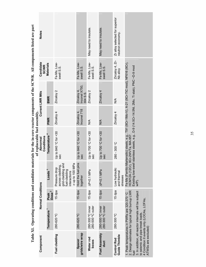
35
Tab
le X
I. O
pera
ting
cond
ition
s and
can
dida
te m
ater
ials
for
the
in-c
ore
reac
tor
com
pone
nts o
f the
SC
WR
. A
ll co
mpo
nent
s lis
ted
are
part
of
rep
lace
able
fuel
ass
embl
y.
Nor
mal
Con
ditio
ns
Abno
rmal
C
ondi
tions
C
urre
nt L
WR
Mtls
C
ompo
nent
Tem
pera
ture
1Pe
akD
ose 2
Load
s 3
Tem
pera
ture
4PW
RB
WR
Can
dida
te
SCW
RM
ater
ials
Not
es
Fuel
cla
ddin
g 28
0-62
0 ºC
15
dpa
Pr
essu
re d
rop
acro
ss c
ladd
ing,
gr
id-c
ladd
ing
and
fuel
-cla
ddin
g in
tera
ctio
ns
up
to 1
00 M
Pa
Up
to 8
40 C
for <
30
sec
Zirc
aloy
4
Zirc
aloy
2
Fe-M
s, L
ow-
swel
l S.S
.
Spac
er
grid
s/w
ire w
rap
280-
620
ºC
15 d
pa
Hol
d th
e fu
el p
ins
toge
ther
Up
to 8
40 C
for <
30
sec
Zirc
aloy
4,
Inco
nel 7
18
Zirc
aloy
4,
Inco
nel X
750,
30
4 S.
S.
Fe-M
s, L
ow-
swel
l S.S
.
Wat
er ro
d bo
xes
280-
300
ºC in
ner
280-
500
ºC o
uter
15
dpa
P<
0.1
MPa
U
p to
700
C fo
r <30
se
cN
/AZi
rcal
oy 2
Fe
-Ms,
Low
-sw
ell S
.S.
May
nee
d to
insu
late
.
Fuel
Ass
embl
y du
ct
280-
500
ºC in
ner
280-
300
ºC o
uter
15
dpa
P<
0.1
MPa
U
p to
700
C fo
r <30
se
cN
/AZi
rcal
oy 4
Fe
-Ms,
Low
-sw
ell S
.S.
May
nee
d to
insu
late
.
Con
trol
Rod
G
uide
Thi
mbl
e 28
0-30
0 ºC
15
dpa
Lo
w h
ydra
ulic
an
d th
erm
al
stre
sses
280
- 300
CZi
rcal
oy 4
N
/AZi
rcal
oy 4
, Zr-
Nb
allo
y Zr
allo
y se
lect
ed fo
r sup
erio
r ne
utro
n ec
onom
y.
1. P
eak
tem
pera
ture
s in
PW
Rs
are
320-
370
C2.
Des
ign
estim
ates
for t
ypic
al h
igh
burn
up L
WR
fu
el3.
In a
dditi
on, a
ll re
acto
r int
erna
ls w
ill be
sub
ject
to
sei
smic
and
pip
e br
eak
load
s.
4 C
ondi
tion
II ev
ents
onl
y (L
OC
As, L
OFA
s,
ATW
Ss a
re e
xclu
ded)
Fe-M
s (F
errit
ic-M
arte
nsiti
c) s
teel
s, e
.g.,
T91
(9C
r-1M
o-V)
, A-2
1 (9
Cr-T
iC m
od),
NF6
16 (9
Cr),
H
CM
12A
(12C
r), 9
Cr-2
WVT
a, M
A-95
7.
Exis
ting
low
-sw
ell s
tain
less
ste
els,
e.g
., D
-9 (1
4.5C
r-14.
5Ni,
2Mo,
Ti s
tab)
, PN
C ~
D-9
mod
w
/P).

36
Tab
le X
II.
Ope
ratin
g co
nditi
ons a
nd c
andi
date
mat
eria
ls fo
r th
e co
re st
ruct
ural
supp
ort r
eact
or c
ompo
nent
s of t
he S
CW
R.
Nor
mal
Con
ditio
nsAb
norm
al
Con
ditio
ns
Cur
rent
LW
R M
tlsC
ompo
nent
Tem
pera
ture
1
Peak
Dos
e 2
Load
s 3
Tem
pera
ture
PW
RB
WR
Can
dida
te
SCW
RM
ater
ials
Not
es
Upp
er G
uide
Su
ppor
t(U
GS)
pla
te
280
ºC u
pper
500
ºC lo
wer
0.
021
dpa
Sign
ifica
nt h
ydra
ulic
an
d th
erm
al lo
ads
Low
er s
ide
at u
p to
700
C fo
r <30
se
c
304L
S.S
30
4L S
.S.
Adva
nced
S.S
., Fe
-Ms
Mus
t ins
ulat
e be
twee
n th
e re
gion
ab
ove
the
core
(500
C) a
nd th
e up
per p
lenu
m (2
80 C
) to
limit
the
ther
mal
load
s in
the
UG
S.
Cal
andr
iaTu
bes
280
ºC in
ner
500
ºC o
uter
(w
/o
insu
latio
n)
0.02
1 dp
a Si
gnifi
cant
hyd
raul
ic
and
ther
mal
load
s 28
0C
inne
r 70
0C
out
er
N/A
N/A
Adva
nced
S.S
., Fe
-Ms
Mus
t ins
ulat
e to
lim
it th
e he
at
trans
fer f
rom
the
cool
ant t
o th
e m
oder
ator
and
con
trol t
he th
erm
al
load
s in
the
cala
ndria
tube
s.
Upp
er C
ore
Supp
ort (
UC
S)
plat
e
500
ºC
0.02
1 dp
a Si
gnifi
cant
hyd
raul
ic.
Mod
erat
e th
erm
al.
Up
to 7
00 ºC
for
<30
sec
304
S.S.
30
4, 3
04L,
31
6 S.
S.
Adva
nced
S.S
., Fe
-Ms
The
wat
er ro
d bo
x pe
netra
tions
m
ay c
ause
som
e lo
cally
hig
h th
erm
al s
tress
es.
C
R g
uide
tu
bes
280
ºC
0.00
001
dpa
Low
hyd
raul
ic.
Low
th
erm
al.
N/A
304
S.S.
30
4 S.
S.
Adva
nced
S.S
., Fe
-Ms,
304
L,
316L
May
wan
t to
use
the
sam
e m
ater
ial
as fo
r the
UG
S, U
CS,
and
ca
land
ria tu
bes
Low
er c
ore
plat
e 28
0-30
0 ºC
0.
39 d
pa
Sign
ifica
nt h
ydra
ulic
. Lo
w th
erm
al.
Supp
orts
cor
e.
N/A
304L
S.S
30
4L S
.S.
Adva
nced
S.S
, Fe
-Ms,
304
L,
316L
May
wan
t to
use
the
sam
e m
ater
ial
as fo
r the
UG
S, U
CS,
and
ca
land
ria tu
bes
Cor
e Fo
rmer
~2
80-6
00 ºC
67
.1 d
pa
Sign
ifica
nt h
ydra
ulic
. H
igh
ther
mal
. 70
0ºC
304
S.S.
N
/AFe
-Ms,
Low
-Sw
ell S
.S.
Mus
t ins
ulat
e ei
ther
the
core
form
er
or c
ore
barre
l to
cont
rol t
he th
erm
al
load
s in
the
barre
l.
Cor
e ba
rrel
or
shro
ud
280º
C c
ore
regi
on,
500
ºC a
bove
co
re
3.9
dpa
Si
gnifi
cant
hyd
raul
ic.
Hig
h th
erm
al.
N/A
304L
S.S
30
4L S
.S.
Fe-M
s, L
ow-
Swel
l S.S
. M
ust i
nsul
ate
the
core
bar
rel a
bove
th
e co
re re
gion
and
insu
late
eith
er
the
core
bar
rel o
r cor
e fo
rmer
in th
e co
re re
gion
.Th
read
ed
fast
ener
s 28
0-50
0 ºC
<
4 dp
a 4
316
S.S.
/CW
304,
600
, 31
6, 3
16L
Adva
nced
S.S
., IN
-718
, 625
, 690
Th
e cu
rrent
des
ign
is a
n al
l wel
ded
core
form
er a
nd b
arre
l.
1. P
eak
tem
pera
ture
s in
PW
Rs
are3
20-3
70 C
2. D
esig
n es
timat
es fo
r 60y
3.
All
reac
tor i
nter
nals
will
be s
ubje
ct to
sei
smic
an
d pi
pe b
reak
load
s 4.
~ 5
0 dp
a fo
r baf
fle b
olts
and
form
ers
in P
WR
s
Fe-M
s (F
errit
ic-M
arte
nsiti
c) s
teel
s, e
.g.,
T91
(9C
r-1M
o-V)
, A-2
1 (9
Cr-T
iC m
od),
NF6
16 (9
Cr),
HC
M12
A (1
2Cr),
9C
r-2W
VTa,
MA-
957.
Exis
ting
low
-sw
ell s
tain
less
ste
els,
e.g
., D
-9 (1
4.5C
r-14.
5Ni,
2Mo,
Ti s
tab)
, PN
C ~
D-9
mod
w/P
). Ad
vanc
ed s
tain
less
ste
els,
e.g
.,H
T-U
PS (~
PNC
), AL
-6XN
(20C
r-24N
i-6M
o-0.
2Cu-
0.2N
), et
c.

37
3.3.1. Status
There is substantial experience with commercial compositions of austenitic stainless steels and some high nickel alloys in currently operating light water reactors. Typically these components operate at temperatures well below the temperatures at which significant swelling occurs, so that swelling has not been a major problem. However there has been some concern regarding possible swelling in low temperature/low dose rate regimes. Of much greater concern has been the failure of components, after many years in both BWRs and PWRs, as a result of irradiation assisted stress corrosion cracking (IASCC) in both stainless steels and high nickel alloys.
Where temperatures significantly above 300ºC or doses above several dpa are expected, as in the SCWR reactor internals, the structural materials recommended in both Tables XI and XII are primarily ferritic-martensitic steels and low swelling variants of austenitic stainless steels. For these conditions austenitic stainless steels, such as AISI 304 and 316, which have not been tailored for low swelling, cannot be used. The swelling behavior of both alloys is sensitive to small changes in heat-to-heat chemistry and significant dimensional changes in the reactor internals can occur even at doses of ~15 dpa. Extensive R&D programs have been carried out in the U.S. since the mid-1970s under the auspices of the Liquid Metal Fast Breeder Reactor (LMFBR) Cladding and Duct program, the Fusion Materials Program and the Basic Energy Sciences Radiation Effects Program to both understand the mechanisms involved in neutron irradiation induced swelling and to develop alloys with improved mechanical behavior relative to both the 316 austenitic stainless steel composition and the 12 Cr ferritic-martensitic steels such as HT-9. As a result of these and similar efforts in Japan and in the EU, there is now a broad range of options in terms of alloy composition and microstructure that could meet the mechanical loading, temperature and neutron dose operating conditions for the SCWR.
Many of these improved materials have been produced in a variety of product forms on a commercial scale. However, there is little basis at present for predicting the behavior of any of these materials in terms of their stress corrosion cracking and irradiation-assisted stress corrosion cracking behavior under supercritical water conditions; current experience in fossil-fired supercritical steam power plants is of only limited value in this regard (Section 3.1). A high level of resistance to IASCC will be required for all of the reactor core and support structure materials to ensure that the residence times of about 3 years for the fuel assemblies and about 20 years for the support structures can be safely met with adequate margin. The lifetime of the core support components operating at temperatures in the 500-600 C range (Table XII) will also be impacted by the long-term stability of the alloy and the possible transformation of metastable phases present in the initial fabricated condition into various intermetallic phases. These long-term phase changes may result in changes in both the mechanical behavior and in the susceptibility to IASCC.
The range of compositions within the Fe-Cr-Ni alloy system within which alloys with acceptable mechanical behavior and dimensional stability currently exist, or could be developed, may be divided into four broad categories namely, a) austenitic stainless steels, b) ferritic-martensitic steels, c) high alloys (Fe < 50 wt.% ) and d) Ni-based alloys. Consequently there is a fairly broad range of compositions and microstructural space available within which to search for and to develop the required level of resistance to environmental degradation.
Within the austenitic stainless steel family, compositional options include:
a) Composition-restricted 316 stainless steels with nitrogen modifications such as the French breeder program 316 and the Japanese 316 FR,
b) 316- type stainless steel micro-alloyed with Ti, B and P, such as the Japanese PNC 316 alloy (although B is not a desirable alloying element in reactors), and D9 modifications,

38
c) High nitrogen austenitic and possibly duplex (austenite/ferrite) steels, and d) Steels containing Cr and Ni in the 20-30% range such as Al-6XN, and the US HT-UPS alloys.
Compositions are available that have demonstrated low swelling up to doses of 50-100 dpa in both mixed spectrum and fast reactors in the temperature regime of highest swelling in non-tailored alloys, i.e., 450 -550 ºC. It should be noted that many of the low swelling alloys also exhibit superior creep strength relative to 316 stainless steel. The low carbon versions of 304 and 316 are not considered for low dose applications for several reasons:
1. Both are susceptible to IGSCC in LWR core applications,2. Recent experiments at the University of Michigan have demonstrated that both 304L and 316L
are susceptible to stress corrosion cracking in supercritical water, although the 304L is considerably more susceptible than the 316L (MacDonald et. al 2003) and
3. Problems with stress-induced grain boundary cracking at temperatures around 500 ºC. The solid-solution strengthened austenitic alloys (iron-base and nickel-base) apparently run into a limit imposed by intergranular creep cracking at temperatures in this range. (Gourgues and Andrieu 2003, Teysseyre et al. 2003).
However, samples of both these alloys should be included in the program to serve as benchmarks against which to compare performance of the newer alloys.
Ferritic-martensitic steels in the 9-12 % Cr range are intrinsically more swelling resistant than austenitic steels. Low swelling has been demonstrated at doses of 50-100 dpa in neutron irradiations. The early commercial model for these alloys for applications to reactor internals was the Alloy HT-9, containing 12 % Cr and 1 % Mo produced by Sandvik. Newer alloys that show better properties are based on 9 % Cr 1 % Mo such as T91 and a series of reduced activation alloys in which the Mo and Nb are replaced with W, V, and Ta, such as the Japanese F82H and the U.S. 9Cr-2WVTa alloy. Additionally, steels such as NF616 and HCM12A from Japan and E911 from the EU have been developed for 620 ºC operation. Special considerations for ferritic-martensitic alloys are that they generally exhibit a radiation hardening-induced shift of the ductile to brittle transition temperature during irradiation at temperatures below about 420 ºC, and that these alloys generally lose strength relative to austenitic alloys at temperatures above about 500 ºC. The DBTT shift must be considered in designing for low temperature operation or ambient temperature shutdown conditions. Also, ferritic-martensitic steels can experience a phase change in the temperature range of 700 to 800 C (depending heating rate and time at temperature) that results in a significant loss of strength. The high temperature loss of strength may prohibit use of these alloys at the highest temperature locations in the SCWR, especially under the anticipated temperature excursions during abnormal conditions. There is no experience with ferritic-martensitic steels in currently operating reactors.
A class of advanced ferritic steels that has received considerable interest for nuclear applications in recent years is the Oxide Dispersion Strengthened (ODS) steels [Huet 1985, Powell et al. 1986, Dubuisson et al. 1997, Ukai et al. 1998]. In these ODS steels the cubic-centered structure provides the irradiation swelling resistance while the dispersed oxides (e.g., yttrium oxides) provide enhanced high-temperature strength. In fact the high-temperature creep strength of these alloys is exceptional, i.e., at 650 C it can be three to four times larger than for the traditional ferritic-martensitic steel HT-9 [Ukai et al. 1998]. Some grades of this class of alloys exhibit low ductility and large anisotropy in creep strength [Ukai et al. 1998, Dubuisson et al. 1997]. However, these shortcomings can be eliminated by careful selection of the alloying elements, e.g., in Japan a tungsten- and titanium-enriched martensitic ODS alloy of composition Fe-0.19C-10.6Cr-2.35W-0.49Ni-0.93Y2O3-0.43Ti exhibits isotropic creep strength and acceptable ductility (i.e., over 10% total elongation at room temperature).

39
An ODS steel known as Incoloy MA-957 (Fe-13Cr-0.26Mo-0.9Ti-0.26Y2O3) was also irradiated in the EBR-II as cladding of MOX fuel pins at significantly more demanding conditions than expected for the hot SCWR fuel pins, i.e., cladding temperature >620 C, discharge burnup >50,000 MWD/t and fluence >4 1022 n/cm2 (> 20 dpa), and did not fail or show signs of deterioration [Bottcher et al. 2002]. Unfortunately, there currently is no commercial vendor for MA-957. Interestingly, another ODS steel marketed as Incoloy MA-956 (Fe-20Cr-4.5Al-0.5Ti-0.5Y2O3) is being considered for the high-temperature boiler sections of the next-generation supercritical fossil power plants [Wright et al. 2001, Harper 2002], and exhibits good corrosion resistance to air at up to 1100 C [Wright et al. 2001]. However, the formation of a brittle alpha prime chromium phase at temperatures of about 475 C will be a problem for this alloy and it probably cannot be used in the SCWR (Smith 1981). The main issues with all ODS alloys relatively to their application in the SCWR are (i) significant uncertainties regarding their compatibility with the supercritical-water coolant, (ii) high cost of fabrication and (iii) weldability. Nevertheless, because of their potential we recommend inclusion of some ODS alloys (e.g., MA957) in the SCWR materials development program.
For the control rod thimbles we recommend Zircaloy 4 or a zirconium-niobium alloy based upon their proven performance in LWRs at the anticipated low operating temperatures (about 300 ºC) and their very low thermal neutron absorption cross section. The latter will give a significant improvement in neutron economy relative to the steels in the case of the control rod guide thimbles, which are located in the reactor core. It has also been suggested that the water rod boxes could be made of a zirconium-based alloy insulated on the outside with zirconium oxide rather than ferritic-martensitic steel. This would improve the neutron economy by reducing the enrichment requirements. In addition, it might be possible to make the fuel assembly ducts out of a zirconium-based alloy insulated on the outside with zirconium oxide. This would again improve the neutron economy. However, issues relating to the integrity of the bonding of the insulation to the metal and the changes experienced by the insulation and the insulation-metal bond under irradiation and under thermal cycles would need to be resolved before zirconium alloys could be recommended for the water rod boxes or fuel assembly ducts.
In several cases the high nickel alloys have been recommended as alternates to the steels. Their swelling behavior may be acceptable up to reasonably high doses. However, these alloys should be considered only if it is found that low-swelling austenitic steels or the ferritic-martensitic class of alloys do not perform satisfactorily in the supercritical water environment or do not have sufficient strength for applications such as threaded structural fasteners (note that the current SCWR design attempts to minimize the use of threaded fasteners). It should also be noted that one of the recommended alloys, Inconel 718, has been shown to be susceptible to intergranular cracking in supercritical water in one set of recent experiments (Fournier et al. 2001). Irradiation experiments have shown that, under certain temperature and neutron dose conditions, various forms of embrittlement may occur in Ni-based alloys associated with severe radiation hardening, grain boundary solute segregation, or transmutation helium-induced grain boundary failure. It would probably be necessary to develop new metallurgical strategies to mitigate these phenomena under the chosen operating conditions. Nevertheless, because of their extremely high strength, high nickel alloys have been used in the radiation-embrittled state in special applications where operational stresses did not approach their yield strength.
In addition to the four classes of Fe-Cr-Ni alloys discussed above, consideration should also be given to the potential application of ceramic materials such as silicon carbide/silicon carbide composite materials (SiC/SiC). Advances in the materials science of these materials and in fabrication technology have led to strong improvements in fracture toughness and strength properties, hermeticity and resistance to radiation damage, (Jones 2002). These materials have been primarily developed for applications requiring high strength at temperatures well above the operating range of SCWR components and nothing is known regarding their behavior in SC water conditions. Nevertheless, it is possible that SiC/SiC materials could
40
be developed having significant advantages over metallic alloys for components where the lack of ductility and low fracture toughness are not critical issues. Potential SiC composite applications include the fuel assembly ducts, water rod boxes, and control rod guide tubes. In the case of the water rod boxes and fuel assembly ducts, the outer composite layer (or inner layer in the case of the ducts) can be made with a higher inter-fiber porosity, so that the composite layer has a very low thermal conductivity, and acts as an insulator. It is recommended that SiC/SiC materials representing the most recent technology should be included for evaluation in the first phase of the R&D program.
3.3.2. Materials Selection and Development and Qualification Requirements
As described in Section 3.3.1, there are four broad categories of alloys to be considered as candidates for the reactor internal components namely a) austenitic stainless steels, b) ferritic-martensitic steels, c) high alloys (Fe < 50 wt.%), and d) nickel-based alloys. There is insufficient knowledge at present regarding their behavior in supercritical water to rank these alloy categories in terms of general corrosion and resistance to SCC and IASCC. Within each category, there exist numerous compositions that have the basic strength and ductility properties to meet the operating requirements over the projected temperature and stress regimes of the SCWR internals.
The materials program to identify materials solutions for each of the reactor internal components is envisaged in two distinct but overlapping activities consisting of a) research and development activity to define a limited number of prime candidate alloys and b) a materials engineering design data activity. The first activity entails a sequenced set of testing and performance evaluation stages over a 7 year time frame in which an initially large number of potential candidate materials is reduced to a limited number of prime candidates through exposure to, and testing in, increasingly complex and hostile environments. This R&D program is intended to ensure the viability of the SCWR. It will produce the technical data that defines alloy compositions and thermo-mechanical treatments with the demonstrated capability to meet the intended service conditions of the major reactor internal components. The second activity involves a more extensive evaluation and qualification of the prime candidates to develop a materials engineering design database of sufficient breadth and depth to meet code case and licensing requirements. This would encompass repetitive testing to establish confidence limits, and development of information on heat-to-heat variations and on various product forms including welds.
The corrosion and SCC behavior of alloys in supercritical water will be the dominant feature of the initial phases of the R&D program. The initial empirical approach will consist of an alloy screening process to develop information on the broad response of the four alloy categories, as well as the duplex silicon carbide cladding category, and on the effect of specific compositional and microstructural variations within these classes. It will, however, be necessary to underpin the empirical approach with a complementary effort to understand the basic phenomena and controlling mechanisms of SCC in supercritical water. Based on past experience with the complexities of IASCC in LWR environments, it will be essential to adopt an integrated theoretical modeling and experimental approach in order to build the scientific knowledge needed to understand the mechanisms controlling behavior in supercritical conditions and to provide a rational basis for developing improved alloys.
The selection of alloy compositions and conditions for the initial evaluations in supercritical water will be influenced by existing bodies of data in three different areas. Firstly, it will be necessary to include some materials for which there is a substantial body of information on behavior in normal water reactor conditions. These benchmark materials provide a basis for identifying an acceleration of known phenomena, or the development of new phenomena, in supercritical conditions. A second source of information that will be considered in selecting candidate alloys is the experience derived from the operation with a variety of materials in fossil fired supercritical steam power plants. The third guiding factor in alloy selection is the vast body of data on the effects of neutron displacement damage on

41
materials behavior, which has been developed over the past 30 years of LWR, fast breeder reactor, fusion power and basic energy sciences programs worldwide. This database will provide a rationale for the exclusion of alloys based upon well-documented behavior in terms of radiation embrittlement and dimensional instability under the conditions of temperature, mechanical loading and neutron dose projected for the core internals. The screening for corrosion and SCC properties will be carried out in a coordinated program utilizing existing experimental facilities at various U.S. institutions in close collaboration with similar efforts in Japan and in Canada. Also included in this phase of the program will be SiC/SiC composite materials representing the most favorable combinations of fiber properties, inter-phase coatings, and matrix composition.
Based on this initial screening phase work, a reduced number of materials exhibiting promising behavior will be selected for the second phase of the R&D program which will include a) SCC initiation and crack growth rate measurements of irradiated materials, utilizing material subjected to neutron and proton sources, coupled with exposure to simulated SCC water chemistry conditions and b) a series of neutron irradiation experiments to establish the mechanical behavior and dimensional stability of candidate alloys as a function of neutron dose and irradiation temperature. Relatively simple irradiation capsules (e.g., HFIR rabbit-type) could be used to produce large numbers of specimens irradiated to doses up to ~23 dpa for post irradiation controlled extension rate tensile (CERT) and crack growth rate (CGR) tests in supercritical water conditions. Accelerator-based irradiations with ~ 3 MeV protons also provide a means of introducing displacement damage and microstructural changes, from which important information can be derived on the mechanisms of IASCC phenomena and provide guidance on the selection of alloys and metallurgical conditions.
Various irradiation facilities in the U.S. and also in reactors outside the U.S., if needed, will be employed to determine the neutron dose and temperature dependence of a full range of properties including tensile, creep, fatigue, fracture and microstructural and dimensional stability. Advanced small specimen technologies will be utilized to maximize efficient use of irradiation space.
The primary component of the third phase of the R&D program will be the testing of a reduced number of promising candidate materials in a SCW loop to obtain data on corrosion and IASCC resistance in prototypical conditions and provide important water chemistry control data. Figure 18 illustrates the research strategy discussed above.
The phased R&D program will result in the identification of a limited number of prime candidate materials with the potential to meet the requirements of all in-vessel components. The R&D program will produce the materials data on which the SCWR can be confidently based. It will deliver alloy compositions and thermo-mechanical treatments and ceramic composite designs that are demonstrated to meet the intended service conditions of the major reactor internal components. The program will then make a transition into a materials engineering activity, which will provide the extensive materials property database required for design, licensing construction and operation. The product of this phase will be a specification for producing materials in the required product forms, an approved data base on properties, the structural assessment methods required to support design, construction, and licensing, and a reliable basis for the prediction of materials performance throughout the expected lifetime including off-normal events.
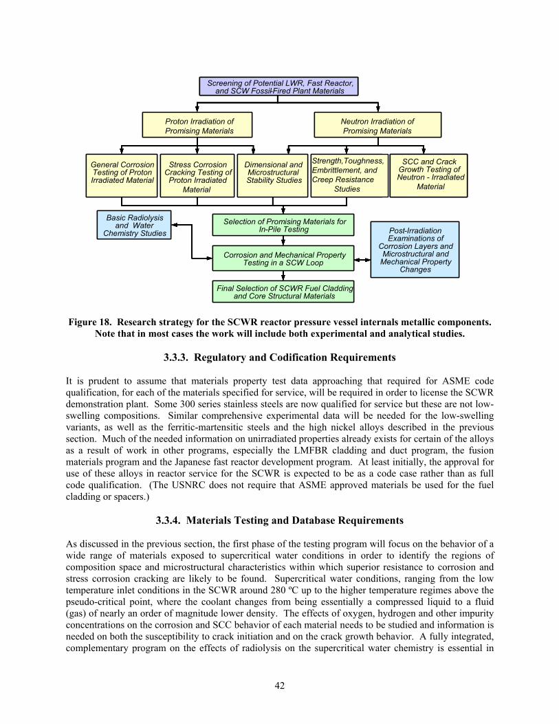
42
Figure 18. Research strategy for the SCWR reactor pressure vessel internals metallic components. Note that in most cases the work will include both experimental and analytical studies.
3.3.3. Regulatory and Codification Requirements
It is prudent to assume that materials property test data approaching that required for ASME code qualification, for each of the materials specified for service, will be required in order to license the SCWR demonstration plant. Some 300 series stainless steels are now qualified for service but these are not low-swelling compositions. Similar comprehensive experimental data will be needed for the low-swelling variants, as well as the ferritic-martensitic steels and the high nickel alloys described in the previous section. Much of the needed information on unirradiated properties already exists for certain of the alloys as a result of work in other programs, especially the LMFBR cladding and duct program, the fusion materials program and the Japanese fast reactor development program. At least initially, the approval for use of these alloys in reactor service for the SCWR is expected to be as a code case rather than as full code qualification. (The USNRC does not require that ASME approved materials be used for the fuel cladding or spacers.)
3.3.4. Materials Testing and Database Requirements
As discussed in the previous section, the first phase of the testing program will focus on the behavior of a wide range of materials exposed to supercritical water conditions in order to identify the regions of composition space and microstructural characteristics within which superior resistance to corrosion and stress corrosion cracking are likely to be found. Supercritical water conditions, ranging from the low temperature inlet conditions in the SCWR around 280 ºC up to the higher temperature regimes above the pseudo-critical point, where the coolant changes from being essentially a compressed liquid to a fluid (gas) of nearly an order of magnitude lower density. The effects of oxygen, hydrogen and other impurity concentrations on the corrosion and SCC behavior of each material needs to be studied and information is needed on both the susceptibility to crack initiation and on the crack growth behavior. A fully integrated, complementary program on the effects of radiolysis on the supercritical water chemistry is essential in
Basic Radiolysis and Water
Chemistry Studies
Proton Irradiation of Promising Materials at U-Mich.
Neutron Irradiation of Promising Materials in HFIR Capsules
General Corrosion Testing of Proton Irradiated Material
at MIT
Stress Corrosion Cracking Testing of Proton Irradiated
Material at U-Mich.
Dimensional and Microstructural
Stability Studies at ANL and ORNL
Strength,Toughness Embrittlement, and Creep Resistance studies at ANL and
ORNL
Selection of Promising Materials for In-Pile Testing
Corrosion and Mechanical Property Testing in an ATR SCW Loop at INEEL
Post-Irradiation Examinations of
Corrosion Layers and Microstructural and
Mechanical Property Changes
Final Selection of SCWR Fuel Cladding and Core Structural Materials
Basic Radiolysis and Water
Chemistry Studies
Proton Irradiation of Promising Materials
Neutron Irradiation of Promising Materials
General Corrosion Testing of Proton Irradiated Material
Stress Corrosion Cracking Testing of Proton Irradiated
Material
Dimensional and Microstructural Stability Studies
Strength,Toughness, Embrittlement, and Creep Resistance
Studies
Selection of Promising Materials for In-Pile Testing
Corrosion and Mechanical Property Testing in a SCW Loop
Post-Irradiation Examinations of
Corrosion Layers and Microstructural and
Mechanical Property Changes
Final Selection of SCWR Fuel Cladding and Core Structural Materials
Screening of Potential LWR, Fast Reactor, and SCW Fossil-Fired Plant Materials
Screening of Potential LWR, Fast Reactor, and SCW Fossil-Fired Plant Materials
SCC and Crack Growth Testing of Neutron-Irradiated Material at U-Mich.
and GE
SCC and Crack Growth Testing of Neutron - Irradiated
Material
Basic Radiolysis and Water
Chemistry Studies
Proton Irradiation of Promising Materials at U-Mich.
Neutron Irradiation of Promising Materials in HFIR Capsules
General Corrosion Testing of Proton Irradiated Material
at MIT
Stress Corrosion Cracking Testing of Proton Irradiated
Material at U-Mich.
Dimensional and Microstructural
Stability Studies at ANL and ORNL
Strength,Toughness Embrittlement, and Creep Resistance studies at ANL and
ORNL
Selection of Promising Materials for In-Pile Testing
Corrosion and Mechanical Property Testing in an ATR SCW Loop at INEEL
Post-Irradiation Examinations of
Corrosion Layers and Microstructural and
Mechanical Property Changes
Final Selection of SCWR Fuel Cladding and Core Structural Materials
Basic Radiolysis and Water
Chemistry Studies
Proton Irradiation of Promising Materials
Neutron Irradiation of Promising Materials
General Corrosion Testing of Proton Irradiated Material
Stress Corrosion Cracking Testing of Proton Irradiated
Material
Dimensional and Microstructural Stability Studies
Strength,Toughness, Embrittlement, and Creep Resistance
Studies
Selection of Promising Materials for In-Pile Testing
Corrosion and Mechanical Property Testing in a SCW Loop
Post-Irradiation Examinations of
Corrosion Layers and Microstructural and
Mechanical Property Changes
Final Selection of SCWR Fuel Cladding and Core Structural Materials
Screening of Potential LWR, Fast Reactor, and SCW Fossil-Fired Plant Materials
Screening of Potential LWR, Fast Reactor, and SCW Fossil-Fired Plant Materials
Screening of Potential LWR, Fast Reactor, and SCW Fossil-Fired Plant Materials
Screening of Potential LWR, Fast Reactor, and SCW Fossil-Fired Plant Materials
SCC and Crack Growth Testing of Neutron-Irradiated Material at U-Mich.
and GE
SCC and Crack Growth Testing of Neutron - Irradiated
Material
SCC and Crack Growth Testing of Neutron-Irradiated Material at U-Mich.
and GE
SCC and Crack Growth Testing of Neutron - Irradiated
Material
43
order to provide information on the radiolytic yields and their recombination rates as a function of density and temperature. Facilities for corrosion and SCC testing in supercritical water exist at MIT, University of Michigan, and the University of Wisconsin. Additionally, facilities for SCC testing exist in Japan both at Toshiba and Hitachi. Also, facilities for supercritical water radiolysis studies exist or are under construction at the University of Wisconsin, Argonne National Laboratory, Notre Dame University, and MIT.
This extensive screening and research effort will be used to down-select materials for the irradiation testing program. The irradiation test program has two aspects: a) the investigation of susceptibility to IASCC phenomena and b) the establishment of the constitutive behavior for creep, swelling, ductility fracture toughness, etc. These two separate irradiation experiment activities may be coupled to some extent. To investigate the susceptibility of materials to IASCC under supercritical water conditions, it is obviously desirable to simulate reactor environmental conditions by exposing materials to the simultaneous effects of displacement damage, ionizing radiation, and stress in a supercritical water environment. This type of environment is difficult to achieve. It is therefore necessary instead to rely on a variety of testing methods and conditions that reproduce to some extent the primary features of the environmental conditions that control corrosion and cracking phenomena.
It is well known that hardening, solute segregation, and embrittlement produced by displacement damage can severely exacerbate intergranular stress corrosion cracking in normal water. In addition, the water in a reactor core environment inevitably becomes more oxidizing because of radiolysis, further aggravating stress corrosion cracking. Even more aggressive conditions may well occur in supercritical water under irradiation. At present there is no information on irradiation-assisted stress corrosion cracking in supercritical water.
Relatively simple irradiation capsules (e.g., HFIR rabbit-type) may be used to produce large numbers of specimens irradiated to doses up to ~5 dpa for post irradiation controlled extension rate tests (CERT) in supercritical water conditions. Although the radiation damage is de-coupled from the other environmental factors, this approach has the advantage of conducting cracking tests in laboratory controlled environments using information on water chemistry derived from separate experiments on radiolysis.
This type of relatively inexpensive irradiation could also be used to provide low dose specimens for the investigation of microstructural and microcompositional evolution. Further, changes in the mechanical properties including changes in the strength, ductility, fracture toughness, and embrittlement caused by low temperature hardening and by high temperature grain boundary phenomena could be investigated. In addition to the irradiation of specimens in helium-filled capsules for CERT testing, it may also be possible to develop an environmental capsule with in-situ monitoring of radiolytic species and chemical corrosion potential, in which the materials are irradiated in contact with water in sealed high-pressure containers. The ongoing irradiation would produce continuous radiolysis leading to products such as oxygen and hydrogen as well as other products such as peroxide that are implicated in IASCC. These specimens could be further tested following irradiation under controlled CERT conditions as above.
Accelerator-based irradiations with ~3 MeV protons also provide a means of introducing displacement damage and microstructural changes, from which important information can be derived on the mechanisms of IASCC phenomena and guidance can be obtained on the selection of alloys and metallurgical conditions. Radiation hardening and microchemical changes can be related to those occurring under neutron irradiation. Following irradiation, specimens can be mechanically loaded in well-controlled SC water chemistry environments to investigate cracking susceptibility.
44
None of the irradiation methods mentioned in the above two paragraphs is an exact duplication of conditions in the SCWR. The neutron irradiations in gas capsules and the proton irradiations in vacuum fail to introduce radiation effects simultaneously with corrosion and/or stress corrosion cracking processes. In addition, the proton irradiations do not introduce radiation damage with consequent changes in properties throughout a specimen, but only affect regions within tens of micrometers of the proton entry surface. In contrast, the neutron irradiations in water capsules do include simultaneous exposure of specimens to irradiation and an oxidizing environment. However, neutron irradiations of closed water capsules suffer in comparison to an exposure in a flowing loop in that the water chemistry is constantly changing in a manner that cannot be easily measured. The problem can be minimized by introducing pH and ECP probes and by providing a low flow rate of refreshed supercritical water. By employing as large a capsule as possible and designing into it water flow by natural circulation, it may be possible to minimize this issue.
The water capsules are being considered specifically for the SCWR project and to our knowledge have not been done before. For this reason the neutron irradiations in water capsules will be subject to an evaluation phase prior to committing to the full cost of including them in the program. The other types of experiments proposed above are not considered to need this type of evaluation phase before committing to include them in the program. Gas capsule neutron irradiations have been the standard method for conducting irradiation testing for many years, and tens of thousands of specimens have been irradiated and tested. Similarly, ion irradiations using protons as well as numerous other types of ions have been carried out for many years in basic and applied research programs.
Based upon a judicious use of these and possibly additional techniques, it is intended to reduce the number of candidate material conditions to a small number of prime candidate alloys for comprehensive testing and evaluation in a pumped loop facility in a test reactor so as to more closely achieve prototypical conditions in flowing supercritical water. However, it should be noted that even such a loop may not completely reproduce the SCWR environment. There is expected to be no truly prototypical environment available until the SCWR itself begins operation. It is therefore recommended that design provisions for the SCWR include an advanced materials irradiation program, in addition to a surveillance program, with capabilities to irradiate specimens of candidate structural materials for possible improvements in subsequent cores or structures and for next generation SCWRs.
Materials showing promise of acceptable performance in supercritical water will be the focus of an irradiation testing program to determine a full range of mechanical behavior and physical properties. Various irradiation facilities in the U.S. and also in overseas reactors, if needed, will be employed to determine the neutron dose and temperature dependence of a full range of properties. For example, the fast neutron flux in the RB positions in HFIR can provide a damage rate similar to that projected for the in-core components shown in Table XII. Lower flux facilities will be employed to assess damage rate effects on microstructural stability and to develop a basis for predicting the lifetime behavior of the structural core components operating in low flux regimes. Properties to be determined include tensile, creep, fatigue, fracture and microstructural and dimensional stability. Advanced small specimen technologies will be utilized to maximize efficient use of irradiation space. For the in-core components of Table XI, specimens of candidate heats with demonstrated resistance to environmental degradation in supercritical water will be irradiated over the full range of design temperatures. The irradiations will be carried out to a recommended 150 % of the nominal expected dose of 15 dpa to provide a margin to cover such contingencies as variability in materials and irradiation environments, as well as to allow for design changes that may affect the intended core lifetime.
The expected doses for the support structures in Table XII are generally much lower than for the in-core components of Table XI. The one exception is the core former, which is expected to reach a dose of ~20 dpa before replacement. As noted above, in order to provide materials and design margins it is
45
recommended that irradiations of candidate materials for this structure be carried out to 150 % the expected dose.
Both conventional post-irradiation mechanical properties tests, to obtain information pertinent to normal operation, and short-term high temperature post-irradiation tests, to obtain information pertinent to off-normal events, will be required. Although there is an existing extensive data base for stainless steels at low temperatures, specimens of specific candidate heats of 304 and 316 stainless steels, including L variants, should be included as benchmark materials in the program to intermediate doses, say 7-10 dpa. In addition to the irradiation program, existing mechanical and physical properties data will be compiled on unirradiated properties for all the starting materials. Much of the information is already available for some alloys intended for reactor service. However, new compositions and advanced alloys proposed for application will need additional testing to develop a database. In particular it will be necessary to initiate a program to determine the long-term stability at 500-650 C of alloys that show promise of acceptable performance is supercritical water and the effects of long-tern thermal exposure on SCC. The long-term aging program will combine phase identification, grain boundary chemistry measurements with thermodynamic modeling to establish a basis for improving long-term stability.
3.3.5. Manufacturing Infrastructure Required
The manufacturing infrastructure is in place for all alloy classes that will be included in the testing program. There is a depth of historical experience in working with suppliers to obtain both small and large heats of these alloys to specifications. Similarly, large-scale fabrication of reactor internals components from selected materials for the SCWR is well within the capabilities of the existing industry in the US, Japan and Europe. It is clear, however, that suppliers will need to have some in-house R&D capabilities in order to produce the required compositions, product forms and microstructures specified for radiation service. This is true also for the duplex silicon carbide cladding option, where the stoichiometric Hi-Nicalon Type S is currently made only in research quantities.
With respect to infrastructure, it must be emphasized that the materials program described here requires extensive capabilities for irradiated specimen work. In turn this translates to a need for substantial and modern hot cell capabilities for irradiated specimen preparation, handling, testing and disposal.
3.4. PUMPS AND PIPING
The issues and concerns regarding the pumps, valves, and piping for the SCWR can be divided into those associated with the feedwater lines and the steam lines. To some measure, issues characteristic of components of the feedwater system will be similar to those being considered in the more conventional advanced LWR technologies, where ASME Section III is the applicable construction code. A wide selection of materials is available in ASME Section III, although the choices for the SCWR may be different for Class 1 components than for Class 2 and Class 3 components. Supplementary information on the materials may be needed to meet the requirements of the applicable appendices of 10 CFR 50. Section III considers fatigue, so this issue must be addressed for the SCWR. Although fatigue-related problems associated with a two-phase coolant may be absent in the SCWR coolant system, the potential for thermal fatigue, low cycle fatigue, and high cycle fatigue, and fatigue crack growth remain.
The issues related to the steam line system are more akin to those addressed in the design, construction, and operation of supercritical fossil power plants. Creep and time-dependent material degradation have been demonstrated to be active in fossil plant steam line systems at temperatures above 370 ˚C (700 ˚F)for ferritic steels and above 425 ˚C (800 ˚F) for austenitic alloys. The philosophy behind the ASME

46
Power Piping Code (B31.1), which covers fossil plant piping, is significantly different from the philosophy of ASME Section III. There is a need for a careful review of the components in the SCWR and to assign the appropriate construction rules. There is a need to review the materials of construction to assure that they are approved by the applicable Code book. Further there is a need to identify potential alternate alloys and to identify the work that would be necessary to develop the appropriate code cases for ASME approval.
3.4.1. Feedwater Pumps
The SCWR feedwater pumps will be low flow/high head pumps located on the feedwater lines outside the containment and are expected to operate at approximately 190 °C (375 °F). It is reasonable to expect that these pumps will resemble in many ways the state-of-the-art pumps developed for supercritical fossil power plants that require similar pressures and throughputs.
3.4.1.1. Status
The pressure, temperature, and throughput of the turbine-driven feedwater supply pumps have been established. The final optimization has not been completed, so the considerations below are intended to suggest some of the options. Similar materials have been considered for the advanced LWRs evaluated in the 1990s.
3.4.1.2. Materials Selection and Development and Qualification Requirements
The pump casing could be a forged low alloy steel such as SA-508 Class 2 or Class 3. An austenitic cladding with controlled delta ferrite content would be required if a low alloy steel is selected. Alternatively, an austenitic stainless steel such as SA-336 Grade F304 could be considered. Because of the low operating temperatures, embrittlement of cast stainless steel pump bodies should not be an issue so a cast grade of stainless steel could be selected. Nevertheless, control of the ferrite content in austenitic castings is desirable. The pump internals could be a high strength casting such as SA-487 CA-6NM-A (normalized and tempered 13Cr-4Ni steel).
3.4.1.3. Regulatory and Codification Requirements
The pump may be constructed to meet the requirements of the ASME Code Section III for Class 2 components. The details of the materials certification, construction, testing, and operation of the pump will meet the General Design Criteria for Nuclear Power Plants Appendix A to 10 CFR 50 and other appendices to this document as they apply.
3.4.1.4. Materials Testing and Data Base Requirements
The compatibility of the materials with the coolant water should be evaluated. A database that includes the operating experiences of pumps operating in the pressure range of interest should be assembled. Utility experience should be brought to bear on issues regarding pump maintenance and reliability. The potential for fatigue, corrosion fatigue, and fatigue crack growth of a flawed component should be assessed.

47
3.4.1.5. Manufacturing Infrastructure Required
The existing infrastructure in the U.S. appears to be adequate to meet the requirements for manufacturing the feedwater pumps to ASME NQA standards. However, at this time there appears to be only one domestic supplier for these pumps (Ingersoll Rand).
3.4.2. Piping
As mentioned above, the piping and valve issues should be separated into those associated with the feedwater and steam lines. The feedwater line piping materials considerations should reflect the current LWR technologies. Valves in the feedwater lines could be manufactured from materials similar to pump casings.
The steam line piping materials considerations could be based to some measure on experiences with the fossil supercritical steam units. As for the piping, valves in the steam lines will be restricted to materials approved in the applicable construction code.
3.4.2.1. Status
The reference piping materials for the SCWR are those currently approved for construction under the rules of ASME Section III for the appropriate component classification. Piping from the inlet and outlet nozzles to the 2nd set of isolation valves will be Class 1 components. Piping from the isolation valves to the turbine or feedwater pumps could include both Class 2 and Class 3 components. The feedwater piping will operate at 280 °C and 25 MPa (27.5 MPa design pressure). The steam lines will operate at 500 °C and 25 MPa (27.5 MPa design pressure). The piping dimensions will depend upon the materials selection but a rough estimate suggests an inside diameter for the two main steam lines of about 375 mm (14.4 inches) and for the two feedwater lines an inside diameter of 400 mm (16 inches), and a wall thickness for both types of lines of around 50 mm (2 inches). The piping system will clearly contain a number of valves, elbows, tees, and wyes. These fittings and other piping components have not been identified.
3.4.2.2. Materials Selection and Development and Qualification Requirements
The choice between ferritic steels and stainless steels for the feedwater line piping is one that must consider the chemistry of the water and the potential for flow assisted corrosion. Experience has shown that flow assisted corrosion is an important degradation mechanism in the feedwater carbon steel piping of both BWRs and PWRs. Also, high and low cycle fatigue are concerns. Piping materials in operating LWRs include carbon steels such as seamless pipe SA-106 Grade C, clad carbon steels, and seamless stainless steels pipes such as SA-312 TP304H, TP304L, TP316L and the like. Of these many materials, the grades that have been included in the LWR environmental strain-fatigue and fatigue crack growth studies would be preferred. Although seam welded piping has been installed in LWRs, it should be avoided unless the piping has been subsequently reworked and renormalized. Wrought products should be preferred over cast products.
The steam line piping is a major concern. The outlet temperature of 500 °C (930 °F) is less than the temperature at which many supercritical fossil power plants operate, but the pressure (25 MPa) is comparable. Whereas ASME Section III has incorporated a wide selection of ferritic piping steels for service to 370 °C (700 °F) and austenitic alloys for service to 425 °C (800 °F), the high-temperature extension Subsection NH is limited to Grade 22 Class 1, Grade 91, and three austenitic alloys (304H stainless steel, 316H stainless steel, and Alloy 800H). The steam line temperature is sufficiently low to
48
enable the use of one of these materials, providing that FAC is not a problem. However, further evaluation is needed if the component life is to be extended from the 34 years in Subsection NH to the intended 60 years of life in the SCWR plan. There are some alternate materials that could be considered. One such material is 316FR stainless steel. This steel qualifies as an “L” grade, yet has properties equivalent to, or superior to, Type 316H stainless steel. The database is sufficient to meet the needs for inclusion into Subsection NH. The steam line piping system between the isolation valve and the turbine could be designed to meet the requirements of B31.1, which would allow a greater choice of materials, for example, Burns and Roe has suggested the use of alloy P92 (9Cr-2W), which is used in fossil-fired supercritical plants. However, supplementary requirements to address fatigue and other damage accumulation mechanisms would be needed.
3.4.2.3. Regulatory and Codification Requirements
A number of issues are expected as a result of the 60-years intended life of the SCWR. The issues arise from experiences of the fossil power piping systems in the last 20 years. One problem is the performance of weldments and seam welded piping. A better understanding is needed of the performance of both similar and dissimilar metal welds. The dissimilar metal welds will be present if an austenitic stainless steel piping system is selected since the RPV and turbine casing will be ferritic steels. One fossil plant experienced cracking in the thick-section dissimilar metal welds after more than 100,000 hours of operation with steam at 540 °C (Baker and Soldan 1963). Another fossil plant operating with 540 °C steam exhibited similar metal weld cracking in 316N stainless steel piping after 96,000 hours (Paterson 1992). The presence of high residual stresses and embrittlement of ferrite or sigma phases are thought to be contributing factors in the cracking of the austenitic steel piping systems. The ferritic steels are known to have cracking problems in thick section weldments. Grade 22 steel and Grade 91 steel are susceptible to cracking in the fine-grained region of the heat-affected zone (Type IV cracking). To mitigate problems with similar and dissimilar metal welds, ASME Subsection NH provides strength reduction factors for weldments. These, and other issues such as aging effects, must be addressed from a Code standpoint.
3.4.2.4. Materials Testing and Data Base Requirements
The extensive data base collected on the candidate piping materials should be re-evaluated in light of the specific environment and operating conditions of the SCWR. The long-time data produced in the time period since ASME Subsection NH should be incorporated into the re-evaluation of the time-dependent allowable stresses and stress intensities. A careful review of the factors contributing to cracking in weldments should be undertaken and techniques to accelerate damage mechanisms should be developed. New technologies should be brought to bear on the life prediction issue. For example, the fitness-for-service assessment methodology developed by the Metals Properties Council is being expanded to include a continuum damage mechanics model suitable for high temperature applications. Factors such as microstructural coarsening, cavitation, and wastage can be accommodated by the model to predict remaining life of a component exposed to long-time high-temperature service. The API 579 document incorporating the continuum damage mechanics model is being incorporated by ASME into a code for continuing operation of equipment. Sophisticated continuing damage models are under development in Europe and Japan, as well.
3.4.2.5. Manufacturing Infrastructure Required
The capability exists on a world-wide basis to produce piping to the quality level needed for the SCWR. However, the capabilities are quite limited in the U.S. for producing large diameter seamless piping so long lead times are to be expected.

49
3.5. POWER CONVERSION SYSTEM
In this section of the plant, steam at about 500 °C and 25 MPa is supplied from the reactor, expanded through the turbine, condensed, cleaned, pumped to 25 MPa, and then heated to 280 °C before re-entering the containment and reactor vessel. The major components of the power conversion system external to the reactor vessel are shown schematically in Figure 19 (Figure 15 provides a more detailed schematic of the SCWR power conversion cycle). These are: the steam turbine and associated valving; the condenser; the demineralizer/condensate polisher; the feedwater preheaters; the deaerator; and the feedwater pumps (the piping and feedwater pumps were discussed in Section 3.4 above).
3.5.1. Turbine
3.5.1.1. Status
In the U.S., fossil-fired supercritical steam power plants operate with steam conditions typically of 540 °C and 25 MPa, while in Europe new plants are operating with steam conditions of 580 °C and 30.5 MPa and in Japan with steam conditions of 600 C and 25 MPa. As a result, there is a well-established manufacturing base for turbines for operation at the supercritical steam conditions of interest in the SCWR, as well as extensive experience in their use. The extent to which this experience is relevant to the SCWR case largely depends on similarities and differences in the quality of the steam, in particular, the extent to which the level and types of impurities in the steam are different from those in fossil-fired practice.
The major design features of steam turbines used in current nuclear power plants have been based on fossil-fired plant experience, with modifications necessitated by safety requirements and the specific manufacturers’ design and materials preferences. One difference is that, whereas in fossil-fired plants the steam exiting the high-pressure turbine is returned to the steam generator for reheating in a separate circuit before being sent to the intermediate-pressure and low-pressure turbines; reheating in LWRs is accomplished with live steam in order to minimize the complication of the steam circuit. Another modification adopted is the addition of moisture separators. The configuration of the turbine for the SCWR is typical of those used in nuclear power plants, and consists of one high/intermediate-pressure turbine followed by three low-pressure turbines. Steam is fed first to the high/intermediate-pressure turbine, from which it passes though a moisture separator and a reheater before being fed to the low-pressure turbines.
Turbine problems have been one of the three leading causes of outages of fossil-fired and nuclear power plants. The main causes of these outages have been reported as: vibration of the turbine-generator unit (mostly blade-related); blade failures; and lubrication/bearings problems. Turbine control problems, typically involving the valving, also have been reported. The materials issues have involved mainly thermal fatigue cracking of rotors and discs; condensate-related corrosion or stress corrosion cracking of the last stages of the turbine; and solid particle erosion of the first stage guide vanes.
Figure 19. Schematic arrangement of the external power conversion circuit.

50
3.5.1.2. Materials Selection and Development and Qualification Requirements
The materials used in the steam turbines in fossil-fired supercritical steam power plants are selected so that their mechanical properties are sufficient for the design life of the plant (usually 30 yrs) without the need for replacement. The materials considerations for the SCWR should be based primarily on fossil plant practice, but also draw to the extent possible on experience from boiling-water reactor (BWR) operation. However, the subcritical steam conditions employed in BWRs (typically 290 °C and 7 MPa) are significantly different from the SCWR conditions. Therefore the first choice for each component will be the alloy used in current fossil supercritical steam practice, with two caveats:
(i) The maximum alloy temperature required in the SCWR is not higher than the maximum alloy temperature allowed in fossil service. If a higher temperature capability is mandated, the best candidate alloy becomes the first one listed in the table that has the required capability.
(ii) The threat of stress corrosion cracking (SCC) from oxidizing or other species resulting from radiolysis of the water is not greater than that from the water conditions prevailing in the supercritical fluid in fossil plants. The ability to maintain the chemistry of the supercritical fluid at the same control points used for the various locations in the water/steam circuit in fossil plants is not known at this time. Similarly, the solubilities of the materials used in the reactor core in the supercritical fluid, the tendency of any dissolved species to be transported into and to deposit in the turbine, and any differences in SCC susceptibility caused by the types and amounts of any transported and deposited species are not known. These needs must be addressed in the materials research program.
The alloys typically used in fossil supercritical steam generators are listed in Table XIII, and alloy compositions are shown in Table XIV.
Table XIII. Summary of alloy candidates for steam turbines.
Component Fossil SCWR Comments Casing cast 0.5%CrMoV
1.25Cr-0.5Mo 2.25Cr-1Mo P122 (HCM12A)
cast 0.5%CrMoV current
developmental Valves cast 0.5CrMoV
Cast P91 Cast mod P91+WCoNbB
cast 0.5CrMoV current developmental (EPRI) developmental (VGB)
Bolting 1%Cr-Mo-V Type 422: 12%Cr Nimonic 80A
1%Cr-Mo-V 12%Cr
currentcurrentcurrent
Rotor & discs
1%Cr-Mo-V forged NiCrMoV A469 Class 8 NiCrMoV A470 Class 8 NiCrMoV A471 Class 8 Type 422: 12%CrMoV mod 12%CrMoV 9%Cr-Co-Mo-W-V-Nb-N-B
1%Cr-Mo-V current, low-alloy, bainitic steels
currently used in Europe developmental
Blades forged Type 403: 12Cr Type 422: 12Cr
Type 403 Type 422
current

51
Rotors and Discs. Rotor and disc problems have been experienced in steam turbines in both fossil and nuclear applications. These problems are related to SCC of the CrMo and NiCrMoV steels used in these components. Attempts to correlate the susceptibility to SCC to alloy microstructural differences (segregation/temper embrittlement) resulting from the initial metallurgical processing routes, or to the operating history of the turbine have not provided much guidance. The consensus from experience from fossil-fired units appears to be that SCC occurs only in wet steam at crevices or locations where access to the steam is limited, and depends on the contaminants present in the steam. Steam in fossil-fired units invariably picks up impurities from sources such as condenser/pump leaks; demineralizer/condensate polisher leaks; de-mineralizer breakdown; and from the feed water and the water treatment chemicals used. Such impurities will deposit from the steam whenever their solubility is exceeded due to changes in steam temperature and pressure. The location in the turbine (the ‘Wilson Line’) where the steam condensate initially forms on the blade surfaces is a function of the steam temperature and pressure so that, depending on turbine load, it moves up and down the low-pressure turbine, alternately wetting and drying the film of condensed water and impurities. The average location of the Wilson Line condensation in steam turbines in fossil-fired units is at the next-to-last row of blades, which are the most prone to pitting. The condensation is sufficient that the salt deposits are subsequently washed from the last row of blades, but that row is subject to erosion by water droplets ejected from the trailing edges of the next-to-last stage vanes.
Table XIV. Alloy compositions (weight %).
Alloy Fe Ni Cr V Mo Nb W C N B* Other T1: 0.5Cr-Mo-V Bal 0.8 0.5 0.5 0.5 0.15 0.8Mn, 0.25Si T11:1.25Cr-Mo Bal 1.25 0.5 0.15 T22 Bal 2.25 1.1 0.06 0.5Mn, 0.5Si T23 (HCM2S) Bal 2.25 0.25 0.1 0.05 1.6 0.07 30 0.345 Mn, 0.2Si T91 Bal 0.4 9 0.22 0.95 0.08 0.1 0.05 0.45Mn,0.35Si Mod P91+W,Co,Nb,B (CB2P)
Bal 9.1 0.2 1.4 0.06 0.11 0.02 112 0.96Co
T92 (NF616) Bal 0.4 9 0.2 0.5 0.07 1.8 0.1 0.05 60 9Cr,Co,Mo,W,V,Nb,N,B Bal 0.69 10 0.18 1 0.04 1 0.14 0.04 SAVE12 Bal 11 0.2 0.07 3 0.1 0.04 0.2Mn, 0.3Si X-20 Bal 12 0.3 1 Type 403 Bal 12 0.15 1 Mn, 0.5Si T122 (HCM12A) Bal 0.34 12 0.2 0.4 0.05 2 0.1 0.05 12CrMoV Bal 10 0.2 1.2 0.05 0.12 0.05 Type 422 Bal 0.75 13 0.25 1 1 0.23 1Mn, 0.75Si NiCrMoV A469 Class 8 Bal 3.6 1.6 0.1 0.45 0.28 0.6Mn, 0.015P,
0.015S, 0.1Si, NiCrMoV A470 Class 8 Bal 3.6 1.6 0.1 0.43 0.28 0.4Mn, 0.012P,
0.012S, 0.01Si, 0.015Al
NiCrMoV A471 Class 8 Bal 3.0 1.35 0.05 0.45 0.28 0.7Mn, 0.012P, 0.015S, 0.2Si
CF3C Bal 10 19 0.03 1.5Mn, 2Si Nimonic 80A 3 Bal 20 0.1 2.5Ti, 1.5Al
*ppm
The contaminants most implicated in SCC are usually chlorides, sulfates, hydroxides, and phosphates of sodium and iron, and there is extensive information on their solubility in steam, as well as the aggressiveness of the various deposits as a function of steam conditions such as its specific volume, and oxygen content.

52
Blades and Vanes. As mentioned in the section on rotors and discs above, SCC is a possibility at crevices and other design features that allow limited access to the steam, and so offer the possibility of corrosion product accumulation. The design criterion for steam turbine blades is high-cycle fatigue: un-notched for the airfoil area, and notched for the blade root area. Locations at which pitting and SCC have been observed in fossil-fired practice have included the attachment of the blades to the discs, so that there is need for careful consideration in the design of the blade-disc mating surfaces to incorporate lessons learned for minimizing susceptibility to SCC. Also as mentioned above, the next-to-last row of blades in the low-pressure turbine is susceptible to pitting corrosion from deposition of impurities condensed from the steam. Such pitting can eventually result in fatigue of the blades and/or imbalance of the turbine.
The last row of blades in the low-pressure turbine also is susceptible to erosion by water droplets shed from the preceding vanes. The severity of water droplet erosion depends on (1) the moisture content of the steam entering the last-but-one stage blades (amount of water); (2) the steam pressure between the next-to-last and last stage (higher steam density will accelerate smaller droplets); and (3) blade tip speed (relative drop velocity from blade to vane). All three factors are determined by the design and operating parameters of the turbine. Preventative measures include design modifications to (a) change the inter-stage spacing, (b) to centrifuge the entrained moisture to the outer casing where it is drained off, or (c) the use of steam reheating.
A major difference between the conditions expected to prevail in the high-pressure turbine of the SCWR and those experienced in BWRs is the potential for solid particle erosion damage to the first row of vanes and blades. This form of degradation occurs when the protective oxide scales that grow on the high-temperature tubes and pipes upstream of the turbine attain a sufficient thickness that they can exfoliate and become entrained in the steam flow. The particles of oxide can be accelerated by the steam so that impact with the turbine vanes or blades can cause significant damage. Since SCWRs will be intended to operate essentially continuously near maximum load at temperatures significantly higher than BWRs, it is expected that their potential for solid particle erosion will be similar to that for the present fleet of fossil-fired supercritical steam power plants.
The potential for solid particle erosion damage depends on the physical dimensions of the flakes of oxide and the frequency of exfoliation events that, in turn, varies significantly among the alloy types that are used for the upstream piping. Exfoliation is triggered when the stresses in the growing oxide scales exceed some critical value; these stresses result from the thickness of the scale (accommodation between the volume of oxide formed and the volume of alloy consumed), as well as from the mismatch in the coefficients of thermal expansion of the scale and the underlying alloy during cooling from operating temperature. The rate of oxide thickening in steam is typically thought to be a function of (time)0.5, and increases exponentially with temperature. Relationships have been developed between oxide scale thickness and tendency for scale exfoliation for some of the alloys used for superheaters and reheaters in fossil plants, and these can provide guidance on the time at temperature at which exfoliation problems might be expected. Some of the protective measures used in fossil-fired plants are applicable to SCWRs, including alloy selection for reduced susceptibility for exfoliation; use of protective coatings for the first rows of blades and vanes; and some vane/nozzle block design measures.
Titanium alloys have been investigated for use for the last two rows of blades in steam turbines in fossil plants because of their potentially higher resistance to SCC, as well as their significantly higher fatigue strength than 12Cr steels, and their much lower susceptibility to fatigue in a corrosive environment. Because of the proprietary position taken by some manufacturers with respect to the design and construction of steam turbines, the extent to which Ti alloys have been adopted and introduced into service, or the extent of service experience is not known at this time. Since materials selection for a

53
SCWR with a planned lifetime of 60 years mandates a conservative approach, Ti alloys will not be further considered at this time.
3.5.1.3. Regulatory and Codification Requirements
It is expected that the components required for the blades and vanes used in the steam turbine for the SCWR will be made from materials that are either the same, or from the same alloy classes as those already qualified for fossil-fired supercritical plant service. In addition, the design of these components, and the processing required to fabricate them will be the same as for other fossil-fired supercritical plant turbines. As a result, it is anticipated that the regulatory and codification requirements will be similar to those for the same components used infossil-fired supercritical plants.
3.5.1.4. Materials Testing and Data Base Requirements
Clarification of Impact of Abnormal Operation on the Turbine. During abnormal operating conditions, the fuel cladding is expected to experience a peak temperature of 840 °C for up to 30 sec, at which point the safety systems will reduce the temperature to the range 280-350 °C in 1-2 minutes, at least in less than 10 minutes. The SCWR turbine will be protected by immediately by-passing it when an abnormal event occurs; as a result we don’t expect the turbine to see these high temperatures; the steam lines might see the high temperatures, but just for 1 or 2 seconds (maybe even less) before the main steam isolation valves close and the containment is isolated.
Definition of the Water Chemistry. In the SCWR system, a major concern is the solubility of the materials that will be in contact with the fluid, and the extent that these species and/or exfoliated corrosion products will be transported to the external circuit, where they may be deposited in the turbine or be accumulated in the demineralizer. The main area of unknown is the quantification of the solubility/corrosion in the prevailing water chemistry and at the higher temperature employed in the SCWR, compared to BWR experience. The range of impurities expected in the steam in the SCWR, and the extent to which they can be controlled, are obviously questions that must be addressed in order to provide a rational basis for assessing the potential threat to the turbine of SCC and associated fatigue. This involves materials for discs and rotors, and materials for blading at temperatures up to the maximum steam temperature. A discussion of the water quality control in fossil-fired plants was presented in Section 3.1.
Quantification of the Threat of Solid Particle Erosion. Since there have been diligent efforts in the U.S. and elsewhere to understand this problem and to find solutions, there exists data for the typical classes of alloys used for the superheater and reheater piping employed in fossil plants upstream of the turbine. The effort required will consist largely of assembling from all available sources data relating to fossil plant experience, the analytical approaches used to analyze those data, and models or algorithms developed for prediction purposes. It is realized that the available data likely will address the behavior of a few, long established alloys, probably T-22 and Type 347/321. Nevertheless, it is expected that there will be sufficient similarity with the oxidation behavior of alloys from similar alloy classes, as well as understanding of reasons for any differences, that acceptable interpretation of the existing data will be possible for the range of alloys needed in the SCWR. As a precaution, however, a task has been built into Section 4 that would allow the generation of data as a check on any extrapolations made for alloys different from those for which plant data are available.
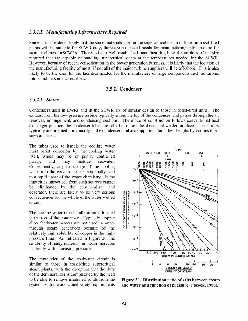
54
3.5.1.5. Manufacturing Infrastructure Required
Since it is considered likely that the same materials used in the supercritical steam turbines in fossil-fired plants will be suitable for SCWR duty, there are no special needs for manufacturing infrastructure for steam turbines forSCWRs. There exists a well-established manufacturing base for turbines of the size required that are capable of handling supercritical steam at the temperatures needed for the SCWR. However, because of recent consolidation in the power generation business, it is likely that the location of the manufacturing facility of most (if not all) of the major turbine suppliers will be off-shore. This is also likely to be the case for the facilities needed for the manufacture of large components such as turbine rotors and, in some cases, discs.
3.5.2. Condenser
3.5.2.1. Status
Condensers used in LWRs and in the SCWR are of similar design to those in fossil-fired units. The exhaust from the low-pressure turbine typically enters the top of the condenser, and passes through the air removal, impingement, and condensing sections. The mode of construction follows conventional heat exchanger practice: the condenser tubes are rolled into the tube sheets and welded in place. These tubes typically are oriented horizontally in the condenser, and are supported along their lengths by various tube-support sheets.
The tubes used to handle the cooling water must resist corrosion by the cooling water itself, which may be of poorly controlled purity, and may include seawater. Consequently, any in-leakage of the cooling water into the condensate can potentially lead to a rapid upset of the water chemistry. If the impurities introduced from such sources cannot be eliminated by the demineralizer and deaerator, there are likely to be very serious consequences for the whole of the water-wetted circuit.
The cooling water tube bundle often is located in the top of the condenser. Typically, copper alloy feedwater heaters are not used in once-through steam generators because of the relatively high solubility of copper in the high-pressure fluid. As indicated in Figure 20, the solubility of many materials in steam increases markedly with increasing pressure.
The remainder of the feedwater circuit is similar to those in fossil-fired supercritical steam plants, with the exception that the duty of the demineralizer is complicated by the need to be able to remove irradiated solids from the system, with the associated safety requirements
Figure 20. Distribution ratio of salts between steam and water as a function of pressure (Pocock, 1983).

55
and procedures, which are however common practice in BWRs.
3.5.2.2. Materials Selection and Development and Qualification Requirements
There do not appear to be any special needs for alloy selection for the condenser in the SCWR design, as long as the water chemistry guidelines developed for the control of corrosion in supercritical fossil plants can be followed. The suggested alloy selection as is shown in Table XV.
Table XV. Summary of alloy candidates for condenser circuit.
Component Fossil SCWR Comments
Condenser tubes Carbon steel, Duplexstainless steels, Titanium
Carbon steel, Duplexstainless steels, Titanium
Based on fossil experience* where SCC on coolant side is an issue
Condenser body Carbon steel Carbon steel Based on fossil experience* Demineralizer Carbon steel Carbon steel Based on fossil experience Deaerator Carbon steel Carbon steel Based on fossil experience Low pressure feedwater heater
Carbon steel Carbon steel Based on fossil experience
High pressure feedwater heater
Carbon steel Carbon steel Based on fossil experience
Condensate pumps F304L F304L Must be weldable *depends on specifics of water chemistry
3.5.2.3. Regulatory and Codification Requirements
The condenser and associated equipment for the SCWR will essentially follow the design practice used for the same components used in LWR service, and will be made from materials that are either the same, or from the same alloy classes as those already qualified. In addition, the processing required to fabricate them will be the same as for other LWR turbines. As a result, it is anticipated that the regulatory and codification requirements will be not be different from those for the same components used in other LWRs.
3.5.2.4. Materials Testing and Data Base Requirements
These depend to the extent that the water chemistry will be different from that for which there is extensive experience in fossil-fired systems. The testing required to make this determination is addressed in Section 3.1
3.5.2.5. Manufacturing Infrastructure Required
No new manufacturing infrastructure will be needed, since these components follow essentially standard LWR and fossil practice.

56
4. SCWR Materials Development Tasks, Costs, and Schedules
4.1. DEVELOPMENT TASKS, COSTS, AND SCHEDULES FOR THE SCWR REACTOR PRESSURE VESSEL MATERIALS
The development tasks for the RPV are dependent on 1) the incorporation of an insulated outlet nozzle to maintain the RPV shell nominal operating temperature at 280 ºC, and 2) consideration of optional higher strength materials to reduce the RPV shell thickness. In the first case, the required tasks and costs are relatively low for the 280 ºC RPV operating temperature, while they would be significantly higher for an operating temperature of 500 ºC associated with an integral hot nozzle (costs not estimated for this report). For the second case, the total tasks and costs are substantial for the necessary developmental costs, but the potential advantages for fabrication and operation of the RPV are significant. The table below is constructed with separate tasks, costs, and schedules for RPV fabrication with current LWR RPV steels and for development of higher strength steels. As stated, only a preliminary evaluation program is given for the optional steels case.
Table XVI. Tasks, schedules, and costs associated with developing a suitable database for the reactor pressure vessel materials.
Task Description Period of Performance
(months)
Cost($K)
RPV With Insulated Hot Outlet Nozzle (280 ºC) and Current LWR Steels Evaluation of steel making and fabrication capabilities for RPV design with current LWR RPV steels (including on-site assembly)
6 150
Demonstration of fabrication capability for RPV thickness to meet minimum mechanical properties in ASME Code (including on-site assembly if needed)
60 12,000
Corrosion, SCC, and IASCC testing of stainless steel cladding for RPV
See section 4.2 See section 4.2
Development of Higher Strength RPV Steels Review and assessment of data for optional higher strength RPV steels
6 150
Conduct preliminary testing of optional high strength steels in thick sections, and develop preliminary welding and NDE capability for optional high strength steels.
60 5,000
Conduct preliminary radiation effects and thermal aging testing
60 3,000
Corrosion, SCC, and IASCC testing of stainless steel cladding for RPV
See section 4.2 See section 4.2
Develop procedures for application of stainless steel cladding to optional high strength steels
24 1,000
Total Test Duration And Costs 60 21,000a
a Does not include costs for SCC, etc. for stainless steel cladding included in 4.2.
57
4.2. DEVELOPMENT TASKS, COSTS, AND SCHEDULES FOR THE SCWR REACTOR PRESSURE VESSEL INTERNAL COMPONENT MATERIALS
Tasks associated with the R&D program described in Section 3.3 to demonstrate the suitability of metallic materials and ceramic composite materials for the major reactor pressure vessel internal components are listed in Table XVII belowc. For the purposes of delineating the needed general tasks, costs, and schedules, the various components given in Tables XI and XII have been grouped by required radiation dose. This arrangement was used with the realization that the tasks will be more complex, test durations will be longer, and costs will be greater with higher dose. Thus, the five fuel assembly components (see Table XI) have been grouped together because they will experience essentially the same peak radiation dose (23 dpa, i.e.15 dpa + margin) and because they will be replaced as a unit. Similarly, some of the core structural components will experience such low radiation doses that radiation experiments will not be planned in those cases. The very low dose components (< 0.5 dpa) comprise the control guide tubes, upper guide support plate (UGS), calandria tubes, upper core support (UCS) plate, and lower core plate. The third group comprises those components that will experience the highest dose (up to 100 dpa, i.e. 67 dpa + margin) and that will not be designed for replacement: the core barrel, core former, and threaded structural fasteners (if any). Obviously, there are cases for which the same material will be a candidate in the different groups. The table below is constructed with separate tasks, costs, and schedules for the three groups as well as for initial screening of all materials in the unirradiated state.
c The required additional materials engineering phase of the work for production of a full materials qualification database would require additional resources. That phase would include irradiation and testing of multiple heats, all product forms, welds and heat affected zones, for example. Extensive repetitive testing would also be required to produce sufficient data for code case requirements.

58
Table XVII. Tasks, schedules, and costs associated with the R&D program for reactor internal materials described in Section 3.3.
Description Period (months)
Cost($K)
Mechanical properties, corrosion and SCC screening of all materials 1. Compilation of available unirradiated mechanical properties data for candidate materials; additional testing where necessary 24 5,000 2. Corrosion and SCC testing in supercritical water 24 10,000 Low Dose Core Support ComponentsInvestigate selected materials based on temperature, design lifetime, corrosion and SCC3. Corrosion and SCC testing in supercritical water at simulated in-reactor chemistry 36 10,000 Replaceable Fuel Assembly Components Investigate selected materials based on temperature, design lifetime, dose, corrosion and IASCC for doses up to 23 dpa4. Irradiation of candidate materials with neutrons and protons, post-irradiation mechanical properties testing, microstructural characterization and corrosion and IASCC testing in supercritical water.
72 75,000 5. Irradiation of candidate materials in supercritical pumped flow loop, post-irradiation mechanical properties testing, microstructural characterization, and corrosion and IASCC testing in supercritical water.
84 50,000* Total Test Duration and Costs 84 150,000** * Does not include neutron charges. ** These costs will be lower if (1) existing university facilities are used, (2) the costs are shared with our international GIF partners, and/or (3) the costs are shared with other Generation IV reactor development programs.

59
4.3. DEVELOPMENT TASKS, COSTS, AND SCHEDULES FOR THE SCWR PUMPS, VALVES, AND PIPING
Tasks associated with selection of materials and application of constructions codes for the pumps, valves, and piping are listed in Table XVIII below. The table below is constructed with separate tasks, costs, and schedules for the three groups of components. It should be recognized that the materials selected for the components may be similar or differ significantly.
Table XVIII. Tasks, schedules, and costs associated with developing materials and fabrication technology for pumps, valves, and piping
Description Period (months)
Cost($K)
Review of construction codes 1. Identify the most likely construction codes for major components of the steam line and feedwater line piping systems 12 400 2. Provide materials data needed to modify construction codes for extended life and new materials 120 4000 PumpsEvaluate materials based on temperature, design lifetime, corrosion, and fatigue3. Perform FAC and corrosion fatigue testing in supercritical water at simulated chemistry 12 1400 ValvesEvaluate materials based on temperature, design lifetime, corrosion and fatigue 4. Perform FAC and corrosion fatigue testing in supercritical water at simulated chemistry 12 1800 5. Evaluate potential for creep-fatigue, thermal fatigue, and dissimilar metal weld cracking of steam line piping valves
48 6,000 Piping6. Perform S-N fatigue, thermal fatigue, and fatigue crack growth testing in simulated supercritical water at simulated chemistry 72
10,000 7. Develop continuum damage models for steam line piping materials 1208. Evaluate potential for dissimilar metal weld cracking in steam line piping
48
8,000 Total Test Duration and Costs 120 31,600

60
4.4. DEVELOPMENT TASKS, COSTS, AND SCHEDULES FOR POWER CONVERSION SYSTEM MATERIALS
The tasks intended to provide the information needed to quantify the influence of supercritical steam on the corrosion, SCC, and IASCC tendencies of the materials candidates for the power conversion system are listed in Table XIX. Some of the information that must be generated is common to the reactor core and the external circuit and, since there is a limited capability for simulating the supercritical steam conditions, some of the testing has been amalgamated with the needs for the core components, and so is addressed in Section 3.2, which is intended to rationalize the testing for which high-pressure loop exposures are needed. The additional corrosion tasks listed in Table XIX address the need for information to evaluate any differences in corrosion product formation, transportation, and deposition in the turbine. The tasks on solid particle erosion are intended to determine the level of assurance available for predicting the tendency for scale exfoliation, and to extend the capability to the materials of interest in the SCWR.
As it is unclear, what chemical species, if any, associated with in-reactor chemistry will appear in the power conversion system, corrosion and SCC testing of materials associated with the power conversion system in supercritical water at simulated in-reactor chemistry, have not been costed.
Table XIX. Tasks, Schedules, and Costs Associated with Power Conversion System Materials.
Description Period (months)
Cost($K)
Corrosion And SCC In Supercritical Steam Evaluation of the corrosion behavior in supercritical steam to extend the existing database on SCC and IASCC 1. Compilation of available information on solubility of materials of interest in supercritical steam, and measurements where necessary 36 800 2. Evaluation of understanding of the factors affecting condensation and subsequent fate of corrosive species in steam turbines 24 5003. Corrosion and SCC testing in supercritical water 36 12,000 Evaluation Of Solid Particle Erosion PotentialDevelop a capability to predict oxide scale growth, frequency and mode of scale spallation from materials upstream of the turbine in supercritical steam 4. Collection and evaluation of available information of solid particle erosion in supercritical steam from fossil experience
24600
5. Testing to validate the predictive capability 36 900 Total Test Duration and Costs 60 14,800

61
ReferencesBaker R. A., and H. M. Soldan, “Service Experiences at 1050F and 1100F of Piping of Austenitic Steels,” pp. 4-85 to 4-84 in Joint International Conference on Creep, Inst. Of Mechanical Engineers, London, 1963. Bartels, David, and Chuck Jonah, Argonne National Laboratory; and Paul Wilson, Mark Anderson, and Robert Agasie, University of Wisconsin, Madison; Neutron and Beta/Gamma Radiolysis of Supercritical Water, 3rd Supercritical Information Exchange Meeting, University of Wisconsin, Madison, WI, April 29 & 30 2003. Bilanin, W.J., R. L. Jones, and C. S. Welty, “Water chemistry guidelines for BWRs,” Proc. 45th
International Water Conference, Pittsburgh, Pennsylvania, 1984. Bottcher J. et al., "ODS Steel Clad MOX Fuel-Pin Fabrication and Irradiation Performance in EBR-II", Nuclear Technology, Vol. 138, pp. 238-245, June 2002. Cowan R. L., “The Mitigation of IGSCC of BWR Internals with Hydrogen Water Chemistry”, Proceedings of the 7th International Conference on Water Chemistry of Nuclear Systems,Bournemouth, England, October 13-17, 1996. Cox, B., “Degradation of Zirconium Alloys in Water-Cooled Nuclear Reactors”, Proceedings of the Third International Symposium on Environmental Degradation of Materials in Nuclear Power Systems—Water Reactors, G. J. Theus and J. R. Weeks, eds., The Metallurgical Society, Inc., pp. 65-76, 1998. Diercks, D.R., W. J. Shack, H. M. Chung, and T. F. Kassner, Review of the Proposed Materials of Construction for the SBWR and AP600 Advanced Reactors, Report No. NUREG/CR-6223, ANL-94/13, 1994. Dooley, R. B., and W. McNaughton, “Boiler Tube Failures: Theory and Practice,” Vols. 1-3, Electric Power Research Institute, Palo Alto, California, 1996. Dubuisson, P., R.Schill, M.P.Hugon, I.Grislin, J.L.Seran, “Behavior of an Oxide Dispersion Strengthened Ferritic Steel Irradiated in Phenix”, Effects of Radiation on Materials: 18th Symposium,ASTM STP 1325, 1997. EPRI Guideline Manual on Instrumentation and Control for Fossil Plant Cycle Chemistry, EPRI Report No. CS-5164, Electric Power Research Institute, Palo Alto, California, April 1987. EPRI Report No. GS-7556: Monitoring Cycle Water Chemistry in Fossil Plants, Vols. 1-3, Electric Power Research Institute, Palo Alto, California, October 1991. European Commission, DG-JRC - Institute for Advanced Materials, Joint Research Centre, Effect of Irradiation on Water Reactors Internal, AMES Report No. 11, Volume 2, DG XI/C/2, May 1997. Fournier, L., et al., "Stress Corrosion Cracking of Nickel Base Superalloys in Aerated Supercritical Water", Paper 01361, Symposium T-5A-90, NACE, 2001. GIF, A Technology Roadmap for the Generation IV Nuclear Energy Systems, GIF-002-00, also available at http://gif.inel.gov/roadmap/generation_iv_technology_roadmap.pdf, December 2002. Gourgues, F., and E. Andrieu, "High-temperature, oxidation-assisted intergranular cracking resistance of a solid-solution-strengthened nickel base alloy," Materials Science and Engineering, A351 39-55, 2003. Hannien H., and I. Aho-Mantila, Environment-Sensitive Cracking of Reactor Internals, Proceedings of the Third International Symposium on Environmental Degradation of Materials in Nuclear Power Systems—Water Reactors, G. J. Theus and J. R. Weeks, eds., The Metallurgical Society, Inc., pp. 77-92, 1998. Harper, M.A., “Improved ODS Alloys for Heat Exchanger Tubing”, Proceedings of the 16th Annual Conference on Fossil Energy Materials (NETL-2002), Baltimore, April 22-24, 2002.
62
Hettiarachchi, S., “Noble Metal Chemical Addition… from Development to Commercial Application”, Proceedings of the 7th International Conference on Nuclear Engineering (ICONE-7),Tokyo, Japan, April 19-23, 1999. Huet, J.J., “Fabrication and Mechanical Properties of Oxide Dispersion Strengthening Ferritic Alloy Canning Tubes for Fast Reactor Fuel Pins”, Nuclear Technology, Vol.70, pp.215, 1985. IAEA, Assessment and management of ageing of major nuclear power plant components important to safety: Steam generators, TECDOC-981, Chapter 5, 1997. Jaffee, R. I., “Metallurgical problems and opportunities in coal-fired steam power plants,” Met. Trans. A, 10, 139-164, 1979. Jones, R., “Advanced Ceramic Composites for High Temperature Fission Reactors”, Pacific Northwest National Laboratory, NERI-PNNL-14102, November 2002 Kataoka, K., et al., “Development Project of Supercritical-water Cooled Power Reactor”, Paper 1034, Proc. 2002 ICAPP, Hollywood, Florida, June 2002. Lin, C. C., “Hydrogen Water Chemistry Technology in BWR’s,” Nuclear Technology, 130, 1, p. 59-70, 2000. Lin, C. C., Radiochemistry in Nuclear Power Reactors, NAS-NS-3119, National Academy Press, 1996. MacDonald, P. E., et. al, Quarter 7 Report for NERI Project 2001-001, Feasibility Study of Supercritical Light Water Cooled Reactors for Electric Power Production, INEEL, July 31, 2003. McKinley, J., S. Teysseyre, G. S. Was, D. B. Mitton, H. Kim, J-K Kim, and R. M. Latanision, “Corrosion and Stress Corrosion Cracking of Austenitic Alloys in Supercritical Water”, GENES4/ANP2003, Kyoto, JAPAN Paper 1027, Sep. 15-19, 2003. Nikolaev, Yu. A., et. al., “Radiation embrittlement and thermal annealing behavior of Cr-Ni-Mo reactor pressure vessel materials,” J. Nuc. Matls., 226, 144-155, 1995. NRC/GNB Technical Meeting, White Flint Number 1, Rockville, MD, 12-13 December 2001. Roberts, J.T.A., Structural Materials in Nuclear Power Systems, Plenum Press, New York (1981). Paterson, S. R., “An Engineering Evaluation of Service Degraded 316N Main Steam Piping Weldments,” pp. 245 to 256 in Creep-Characterization of Damage and Life Assessment, ASM International, Materials Park, Ohio, 1992. Pocock, F. J., and A. Banweg, “Current Waterside Corrosion Concerns in Fossil Utility Steam Generators, pp. 29-67 in Corrosion in Fossil Fuel Systems, I. G. Wright, Ed., The Electrochemical Soc., Proceedings Volume 83-5, 1983. Pocock, F. J., “Water chemistry guidelines for once-through steam generators and drum boilers,” presented at the EPRI Symposium on Utility Power Plant Water Chemistry, Atlanta, Georgia, 1985. Pocock, F. J., “Utility water chemistry practice in the United States,” presented at the Conference of the International Committee on the Properties of Steam, Dusseldorf, Germany, 1986. Powell, R.W., G.D.Johnson, M.L.Hamilton, F.A.Garner, “LMR Cladding and Duct Materials Development”. Proceedings of the International Conference on Reliable Fuels for Liquid Metal Reactors, Tucson (AZ), September 7-11, 1986. Scott, P. M., “Review of Environmental Effects on Pressure Vessel Integrity”, Proceedings of the Third International Symposium on Environmental Degradation of Materials in Nuclear Power Systems—Water Reactors, G. J. Theus and J. R. Weeks, eds., The Metallurgical Society, Inc., pp. 15-29, 1998. Seth, B. B., “US developments in advanced steam turbine materials,” pp. 519-542 in Advanced Heat-Resistant Steel for Power Generation, R. Viswanathan and J. Nutting, Eds., IOM Communications Ltd., Book No. 708, 1999. Smith, W. F., Structure and Properties of Engineering Alloys, Pages 279-281, McGraw-Hill Book Co., New York, 1981.

63
Stofanak, R. J. and Matuszuk, K., “Irradiation Embrittlement Behavior of High Strength Low Alloy Steels Containing About 3.3% Nickel,” Proceedings of Tenth International Conference on environmental Degration of Materials in Nuclear Power Systems – Water Reactors, The Minerals, Metals and Materials Society, Warrendale, PA, 2001. Teysseyre, S., J. McKinley, G. S. Was, D. B. Mitton, H. Kim, J-K Kim and R. M. Latanision,"Corrosion and Stress Corrosion Cracking of Austenitic Alloys in Supercritical Water", 11thInternational Conference on Environmental Degradation of Materials in Nuclear Power Systems - Water Reactors, G. S. Was, L. Nelson and P. King, eds., American Nuclear Society, La Grange Park, IL, in press. Ukai, S., T.Nishida, T.Okuda, T.Yoshitake, “Development of Oxide Dispersion Strengthened Steels for FBR Core Application, (II) Morphology Improvement by Martensite Transformation”, Journal of Nuclear Science and Technology, Vol.35, No.4, pp.294-300, 1998. Wright, I.G. et al. “Oxide Dispersion-Strengthened Alloy Development”, ORNL, Fossil Energy Advanced Research Materials program, 2001.