fundamentals of nuclear engineering · 1. define stages of nuclear chain reaction cycle 2. define...
TRANSCRIPT
1
Fundamentals of Nuclear Engineering
Module 7: Nuclear Chain Reaction Cycle
Dr. John H. Bickel
2
3
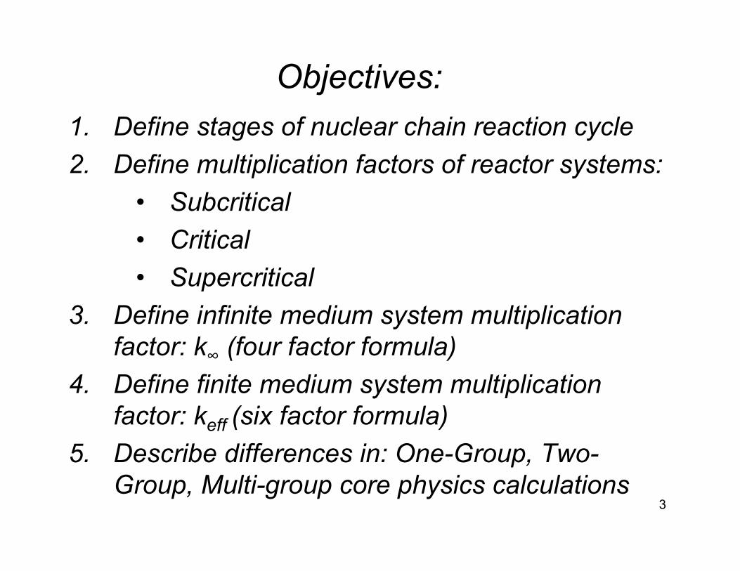
Objectives:1. Define stages of nuclear chain reaction cycle2. Define multiplication factors of reactor systems:
• Subcritical• Critical • Supercritical
3. Define infinite medium system multiplication factor: k∞ (four factor formula)
4. Define finite medium system multiplication factor: keff (six factor formula)
5. Describe differences in: One-Group, Two-Group, Multi-group core physics calculations
4
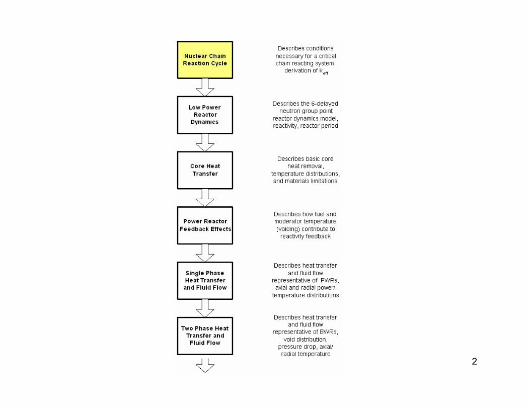
Chain Reacting Systems
5
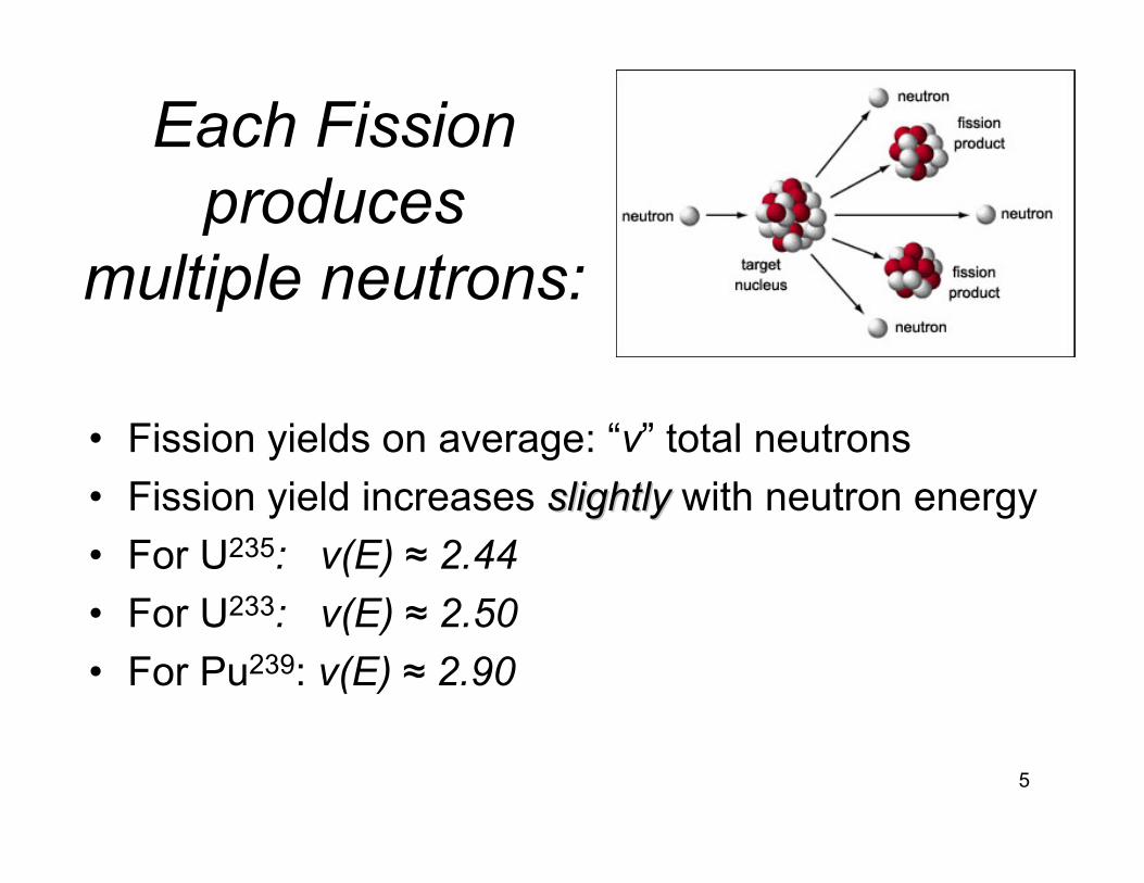
Each Fission produces
multiple neutrons:
• Fission yields on average: “ν” total neutrons• Fission yield increases slightlyslightly with neutron energy• For U235: ν(E) ≈ 2.44 • For U233: ν(E) ≈ 2.50 • For Pu239: ν(E) ≈ 2.90
6
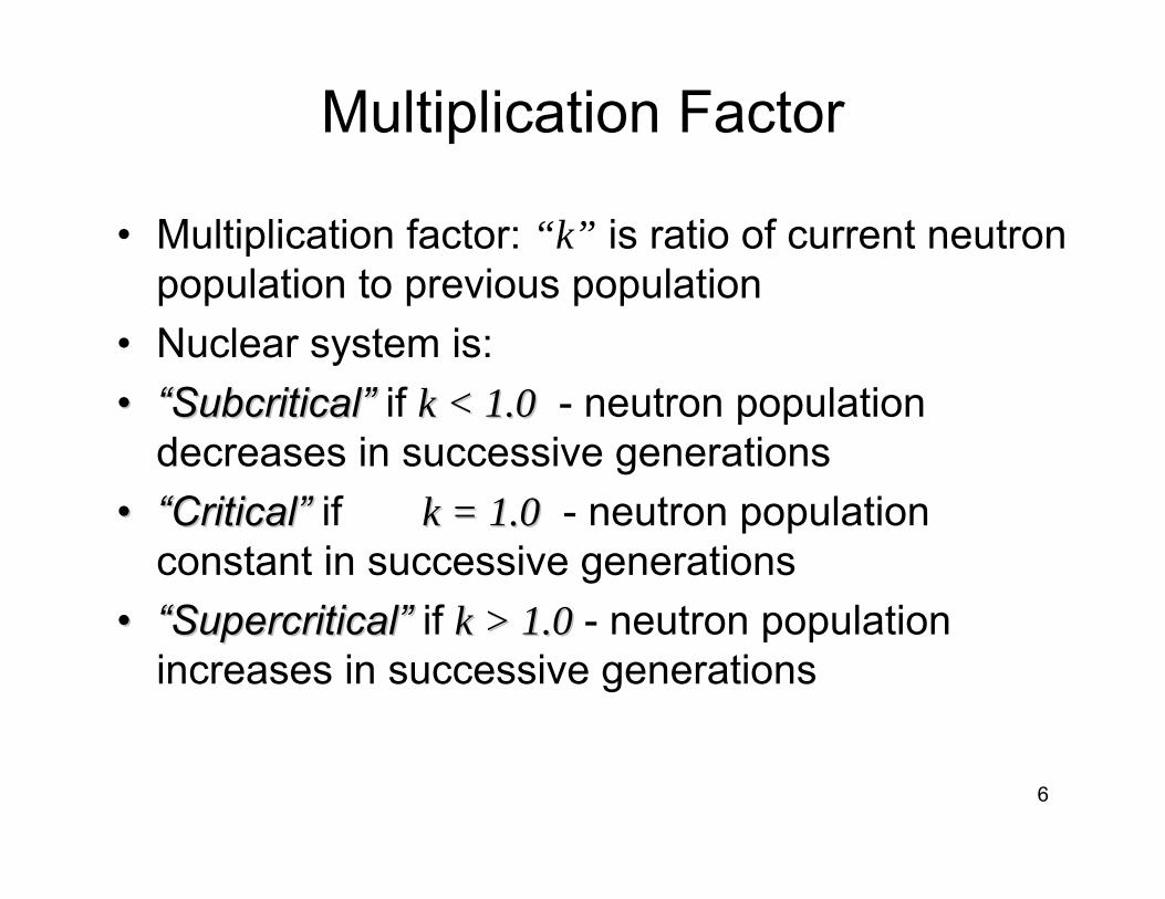
Multiplication Factor
• Multiplication factor: “k” is ratio of current neutron population to previous population
• Nuclear system is: •• ““SubcriticalSubcritical”” if k < 1.0k < 1.0 - neutron population
decreases in successive generations•• ““CriticalCritical”” if k = 1.0k = 1.0 - neutron population
constant in successive generations•• ““SupercriticalSupercritical”” if k > 1.0k > 1.0 - neutron population
increases in successive generations
7
Differences Between: Thermal and Fast Reactors
• Thermal reactors primarilyprimarily rely on thermal neutronsthermal neutrons to initiate fission
• Thermal reactors include a population of fastfast, epithermalepithermal, and thermal neutronsthermal neutrons
• Thermal reactors use some relatively low Alow A--valuevaluemoderator/coolant to slow neutrons down to thermal energy
• Fast reactors rely on fast neutron fissionfast neutron fission processes• Fast reactors must use high Ahigh A--valuevalue coolant (liquid metals)
• Criticality is a measure of net neutron populationnet neutron population, not energy distribution
8
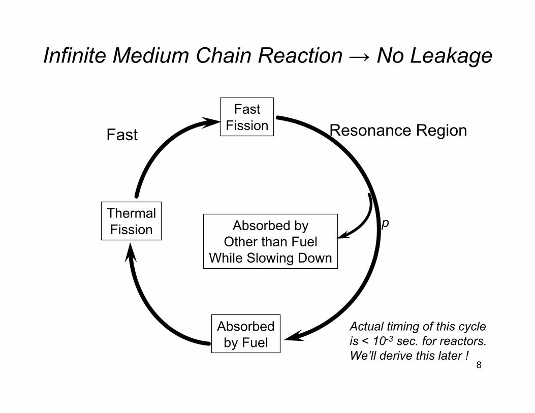
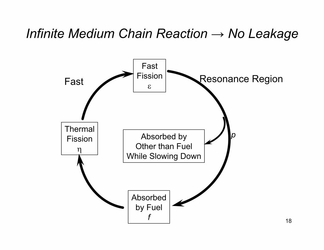
Infinite Medium Chain Reaction → No Leakage
FastFission
ThermalFission
Absorbedby Fuel
Absorbed byOther than Fuel
While Slowing Down
p
Fast Resonance Region
Actual timing of this cycle is < 10-3 sec. for reactors.We’ll derive this later !
9
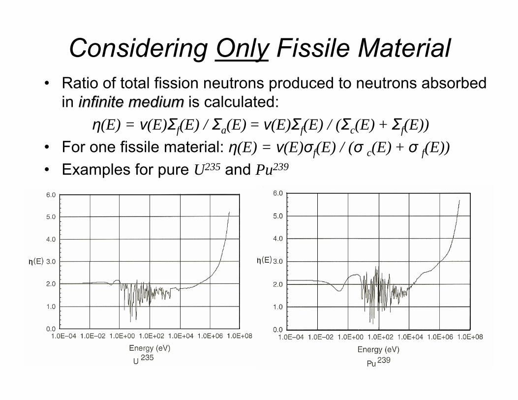
Considering Only Fissile Material• Ratio of total fission neutrons produced to neutrons absorbed
in infinite mediuminfinite medium is calculated:η(E) = ν(E)Σf(E) / Σa(E) = ν(E)Σf(E) / (Σc(E) + Σf(E))
• For one fissile material: η(E) = ν(E)σf(E) / (σ c(E) + σ f(E))• Examples for pure U235 and Pu239
10
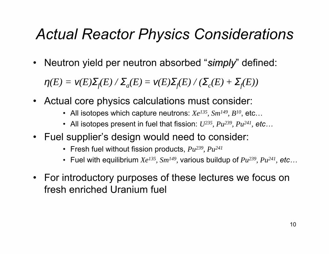
Actual Reactor Physics Considerations
• Neutron yield per neutron absorbed “simplysimply” defined:
η(E) = ν(E)Σf(E) / Σa(E) = ν(E)Σf(E) / (Σc(E) + Σf(E))
• Actual core physics calculations must consider:• All isotopes which capture neutrons: Xe135, Sm149, B10, etc…• All isotopes present in fuel that fission: U235, Pu239, Pu241, etc…
• Fuel supplier’s design would need to consider:• Fresh fuel without fission products, Pu239, Pu241
• Fuel with equilibrium Xe135, Sm149, various buildup of Pu239, Pu241, etc…
• For introductory purposes of these lectures we focus on fresh enriched Uranium fuel
11
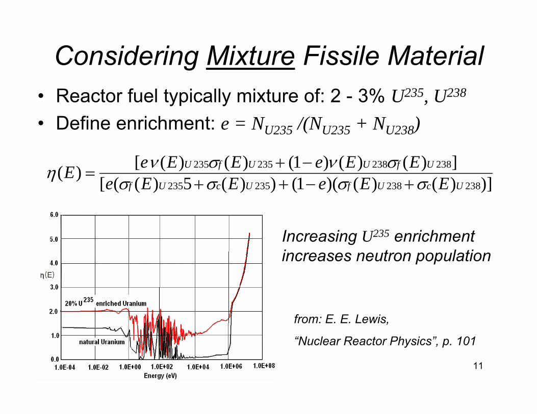
Considering Mixture Fissile Material• Reactor fuel typically mixture of: 2 - 3% U235, U238
• Define enrichment: e = NU235 /(NU235 + NU238)
)])()()(1())(5)(([])()()1()()([)(
238238235235
238238235235
UcUfUcUf
UfUUfU
EEeEEeEEeEEeE σσσσ
σνσνη+−++
−+=
Increasing U235 enrichment increases neutron population
from: E. E. Lewis,
“Nuclear Reactor Physics”, p. 101

12
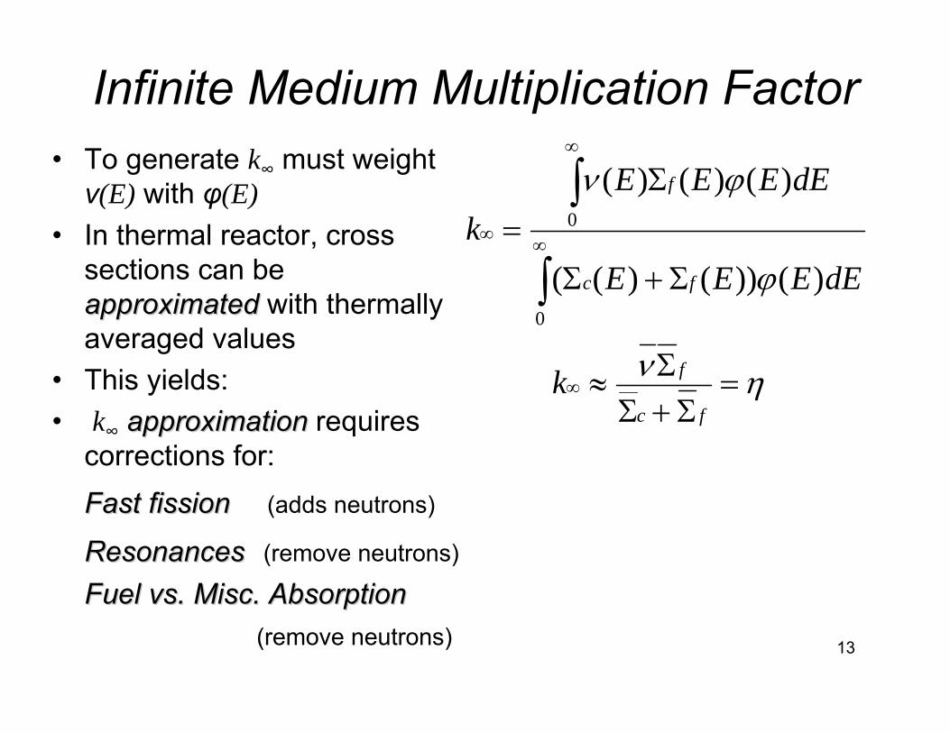
Infinite Medium Multiplication FactorTo generate k∞ must consider:
• Materials other than fissile fuel• Cladding• Coolant/Moderator• Control Rods• Structural Materials• All cause: scattering, thermalizing, capture• These impact φ(E) distribution by: • Shifting neutron density towards thermal energies• Depressing neutron density near resonances
13
Infinite Medium Multiplication Factor• To generate k∞ must weight ν(E) with φ(E)
• In thermal reactor, cross sections can be approximatedapproximated with thermally averaged values
• This yields:• k∞ approximationapproximation requires
corrections for:
Fast fissionFast fission (adds neutrons)
ResonancesResonances (remove neutrons)
Fuel vs. Misc. AbsorptionFuel vs. Misc. Absorption(remove neutrons)
∫
∫∞
∞
∞
Σ+Σ
Σ=
0
0
)())()((
)()()(
dEEEE
dEEEEk
fc
f
ϕ
ϕν
ην =Σ+Σ
Σ≈∞fc
fk
14
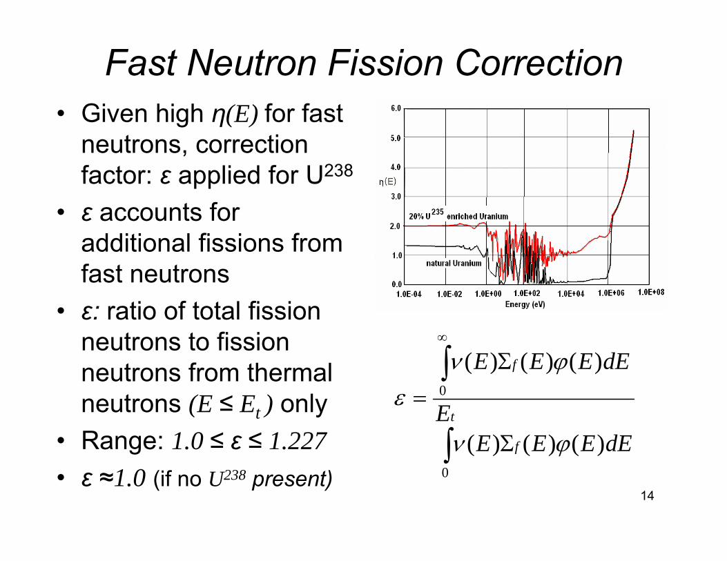
Fast Neutron Fission Correction• Given high η(E) for fast
neutrons, correction factor: ε applied for U238
• ε accounts for additional fissions from fast neutrons
• ε: ratio of total fission neutrons to fission neutrons from thermal neutrons (E ≤ Et ) only
• Range: 1.0 ≤ ε ≤ 1.227• ε ≈1.0 (if no U238 present)
∫
∫
Σ
Σ=
∞
t
f
f
EdEEEE
dEEEE
0
0
)()()(
)()()(
ϕν
ϕνε
15
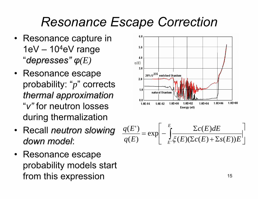
Resonance Escape Correction• Resonance capture in
1eV – 104eV range “depresses”depresses” φ(E)
• Resonance escape probability: “p” corrects thermal approximationthermal approximation“ν” for neutron losses during thermalization
• Recall neutronneutron slowing slowing down modeldown model:
• Resonance escape probability models start from this expression
⎥⎦
⎤⎢⎣
⎡
Σ+ΣΣ
−= ∫E
E EEsEcEdEEc
EqEq
' ))()()(()(exp
)()'(
ξ
16
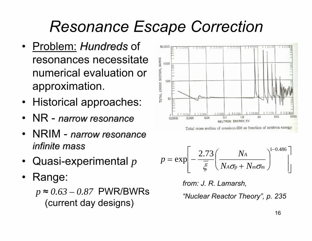
Resonance Escape Correction• Problem: HundredsHundreds of
resonances necessitate numerical evaluation or approximation.
• Historical approaches:• NR - narrow resonancenarrow resonance
• NRIM - narrow resonance narrow resonance infinite massinfinite mass
• Quasi-experimental p• Range:
p ≈ 0.63 – 0.87 PWR/BWRs (current day designs)
⎥⎥⎦
⎤
⎢⎢⎣
⎡⎟⎠⎞
⎜⎝⎛
+−=
− 486.0173.2expmmpA
A
NNNp
σσξ
from: J. R. Lamarsh,
“Nuclear Reactor Theory”, p. 235
17
Thermal Utilization Correction• Thermal neutrons not all absorbed in fuel• Thermal utilization “f” corrects for fraction absorbed
in non-fissile materials
• Typical value: f ≈ 0.94 for PWR/BWR (current day designs)
∫∫
∫
Σ+Σ+Σ
Σ+Σ=
t
cm
t
fcf
t
fcf
EdEEEV
EdEEEEV
EdEEEEV
f
00
0
)()()())()((
)())()((
ϕϕ
ϕ
mcmffcf
ffcf
VVVf
ϕϕϕΣ+Σ+Σ
Σ+Σ=
)()(
18
Infinite Medium Chain Reaction → No Leakage
FastFission
ε
ThermalFission
η
Absorbedby Fuel
f
Absorbed byOther than Fuel
While Slowing Down
p
Fast Resonance Region
19
Optimization of Fuel Assembly Design
20
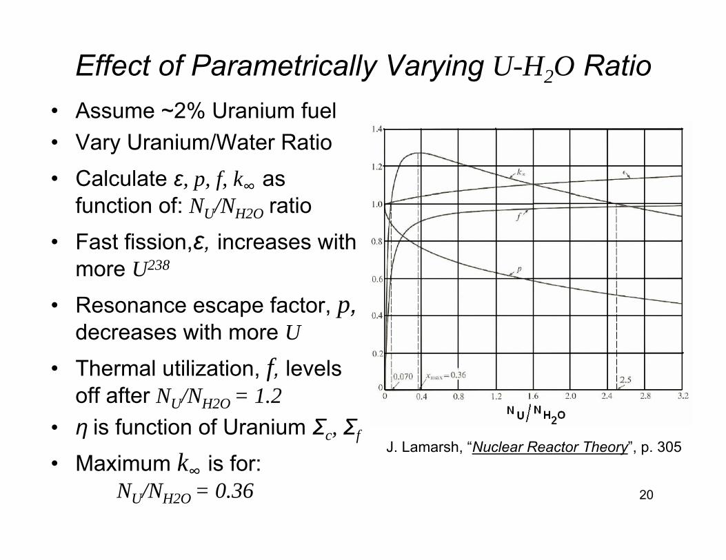
Effect of Parametrically Varying U-H2O Ratio• Assume ~2% Uranium fuel• Vary Uranium/Water Ratio• Calculate ε, p, f, k∞ as
function of: NU/NH2O ratio• Fast fission,ε, increases with
more U238
• Resonance escape factor, p, decreases with more U
• Thermal utilization, f, levels off after NU/NH2O = 1.2
• η is function of Uranium Σc, Σf
• Maximum k∞ is for: NU/NH2O = 0.36
J. Lamarsh, “Nuclear Reactor Theory”, p. 305
21
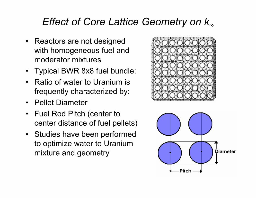
Effect of Core Lattice Geometry on k∞• Reactors are not designed
with homogeneous fuel and moderator mixtures
• Typical BWR 8x8 fuel bundle:• Ratio of water to Uranium is
frequently characterized by:• Pellet Diameter• Fuel Rod Pitch (center to
center distance of fuel pellets)• Studies have been performed
to optimize water to Uranium mixture and geometry
22
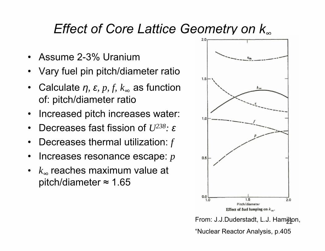
Effect of Core Lattice Geometry on k∞
• Assume 2-3% Uranium• Vary fuel pin pitch/diameter ratio• Calculate η, ε, p, f, k∞ as function
of: pitch/diameter ratio• Increased pitch increases water:• Decreases fast fission of U238: ε• Decreases thermal utilization: f• Increases resonance escape: p• k∞ reaches maximum value at
pitch/diameter ≈ 1.65
From: J.J.Duderstadt, L.J. Hamilton,
“Nuclear Reactor Analysis, p.405
23
Homogenous vs. Heterogeneous
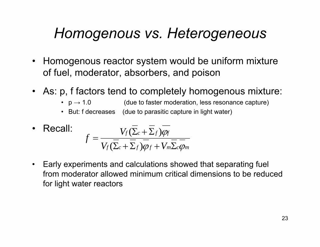
• Homogenous reactor system would be uniform mixture of fuel, moderator, absorbers, and poison
• As: p, f factors tend to completely homogenous mixture:• p → 1.0 (due to faster moderation, less resonance capture)• But: f decreases (due to parasitic capture in light water)
• Recall:
• Early experiments and calculations showed that separating fuel from moderator allowed minimum critical dimensions to be reducedfor light water reactors
mcmffcf
ffcf
VVVf
ϕϕϕΣ+Σ+Σ
Σ+Σ=
)()(
24
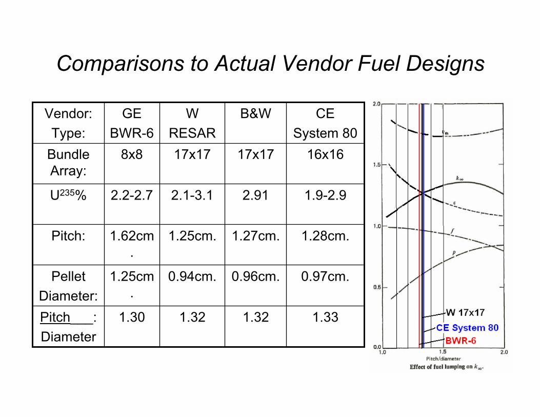
Comparisons to Actual Vendor Fuel Designs
1.331.321.321.30Pitch___:Diameter
0.97cm.0.96cm.0.94cm.1.25cm.
PelletDiameter:
1.28cm.1.27cm.1.25cm.1.62cm.
Pitch:
1.9-2.92.912.1-3.12.2-2.7U235%
16x1617x1717x178x8Bundle Array:
CESystem 80
B&WWRESAR
GEBWR-6
Vendor:Type:
25
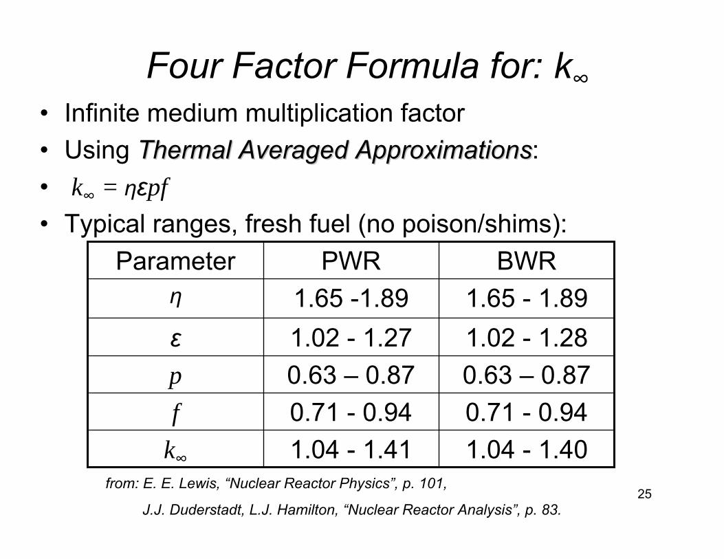
Four Factor Formula for: k∞• Infinite medium multiplication factor• Using Thermal Averaged ApproximationsThermal Averaged Approximations:• k∞ = ηεpf • Typical ranges, fresh fuel (no poison/shims):
1.04 - 1.401.04 - 1.41k∞
0.71 - 0.940.71 - 0.94f 0.63 – 0.870.63 – 0.87p1.02 - 1.281.02 - 1.27ε1.65 - 1.891.65 -1.89η
BWRPWRParameter
from: E. E. Lewis, “Nuclear Reactor Physics”, p. 101,
J.J. Duderstadt, L.J. Hamilton, “Nuclear Reactor Analysis”, p. 83.
26
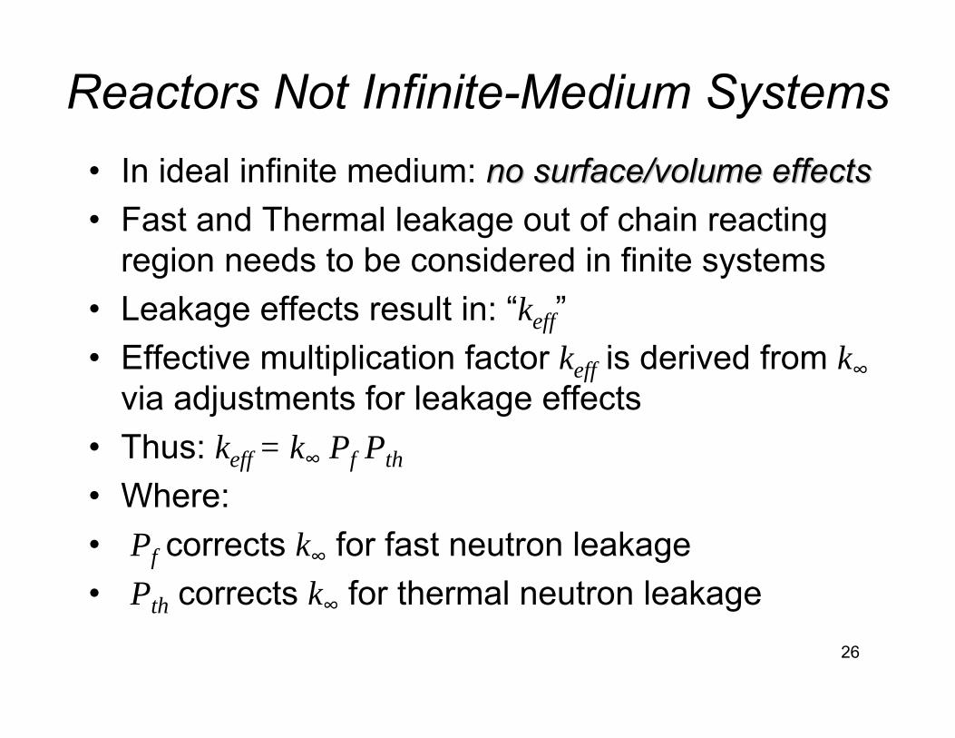
Reactors Not Infinite-Medium Systems • In ideal infinite medium: no surface/volume effectsno surface/volume effects• Fast and Thermal leakage out of chain reacting
region needs to be considered in finite systems• Leakage effects result in: “keff”• Effective multiplication factor keff is derived from k∞
via adjustments for leakage effects• Thus: keff = k∞ Pf Pth
• Where: • Pf corrects k∞ for fast neutron leakage• Pth corrects k∞ for thermal neutron leakage
27
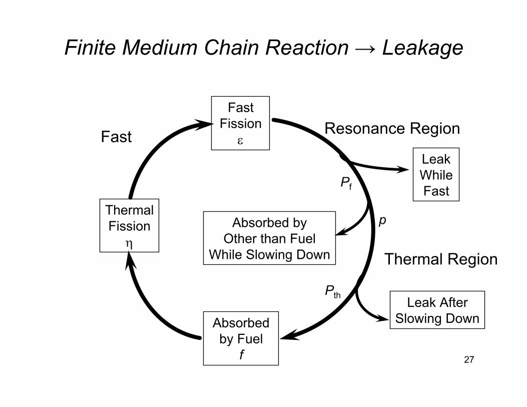
Finite Medium Chain Reaction → Leakage
FastFission
ε
ThermalFission
η
Absorbedby Fuel
f
Absorbed byOther than Fuel
While Slowing Down
p
LeakWhileFast
Pf
Leak AfterSlowing Down
Pth
Fast
Thermal Region
Resonance Region
28
One Group Diffusion Criticality Model
29
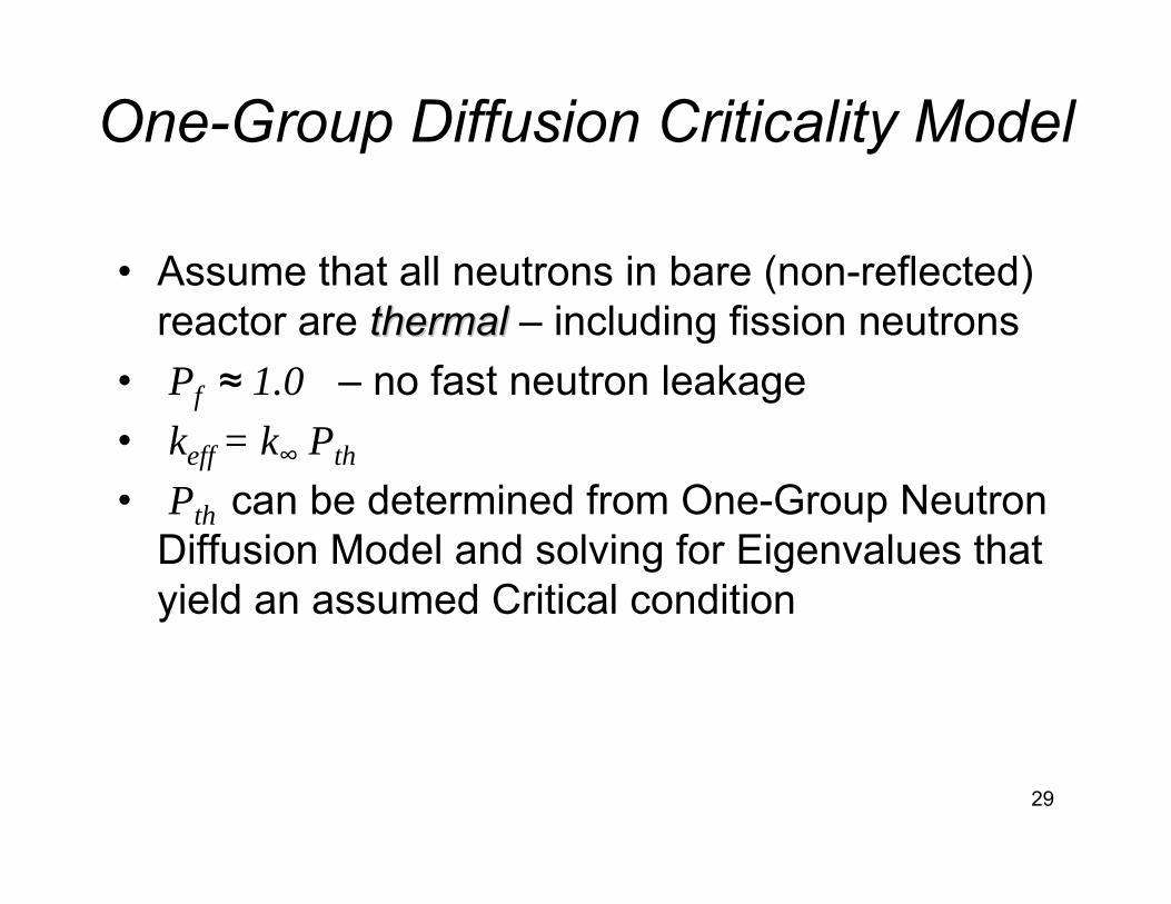
One-Group Diffusion Criticality Model
• Assume that all neutrons in bare (non-reflected) reactor are thermal thermal – including fission neutrons
• Pf ≈ 1.0 – no fast neutron leakage• keff = k∞ Pth
• Pth can be determined from One-Group Neutron Diffusion Model and solving for Eigenvalues that yield an assumed Critical condition
30
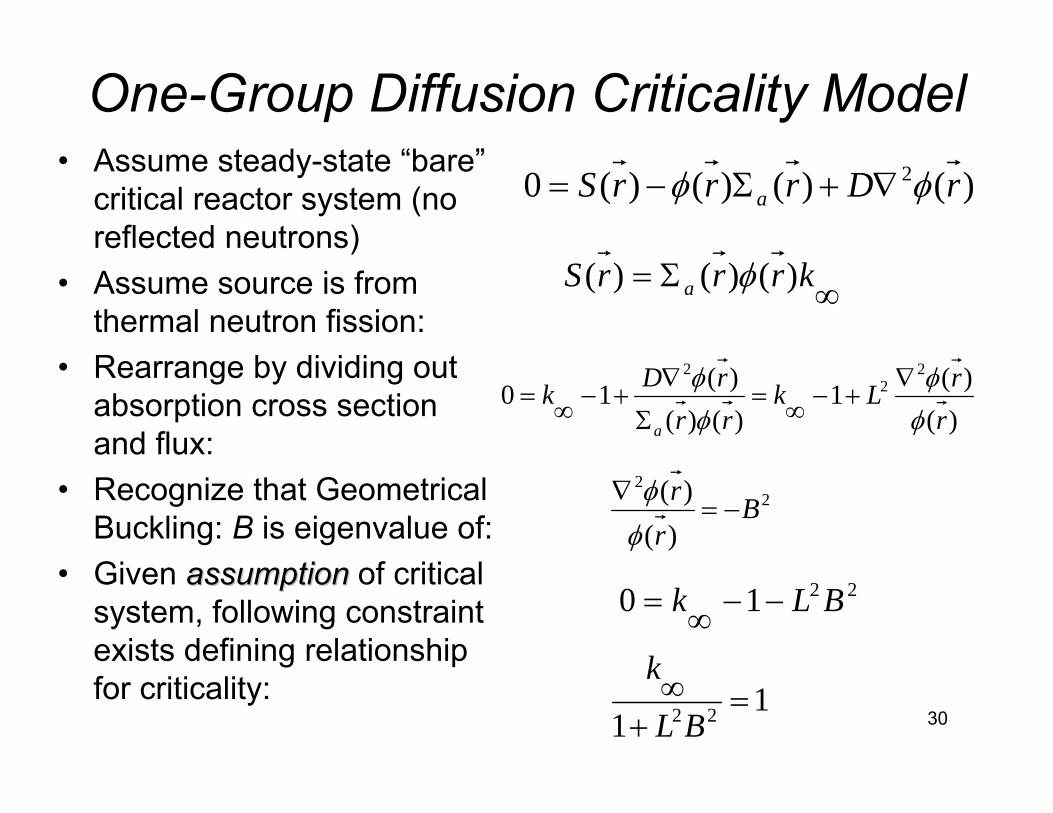
One-Group Diffusion Criticality Model• Assume steady-state “bare”
critical reactor system (no reflected neutrons)
• Assume source is from thermal neutron fission:
• Rearrange by dividing out absorption cross section and flux:
• Recognize that Geometrical Buckling: B is eigenvalue of:
• Given assumptionassumption of critical system, following constraint exists defining relationship for criticality:
)()()()(0 2 rDrrrS a φφ ∇+Σ−=
∞Σ= krrrS a )()()( φ
22
)()( B
rr
−=∇
φφ
)()(1
)()()(10
22
2
rrLk
rrrDk
a φφ
φφ ∇
+−∞=Σ
∇+−∞=
2210 BLk −−∞=
11 22 =+∞
BL
k
31
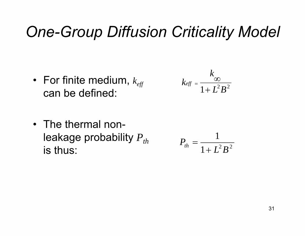
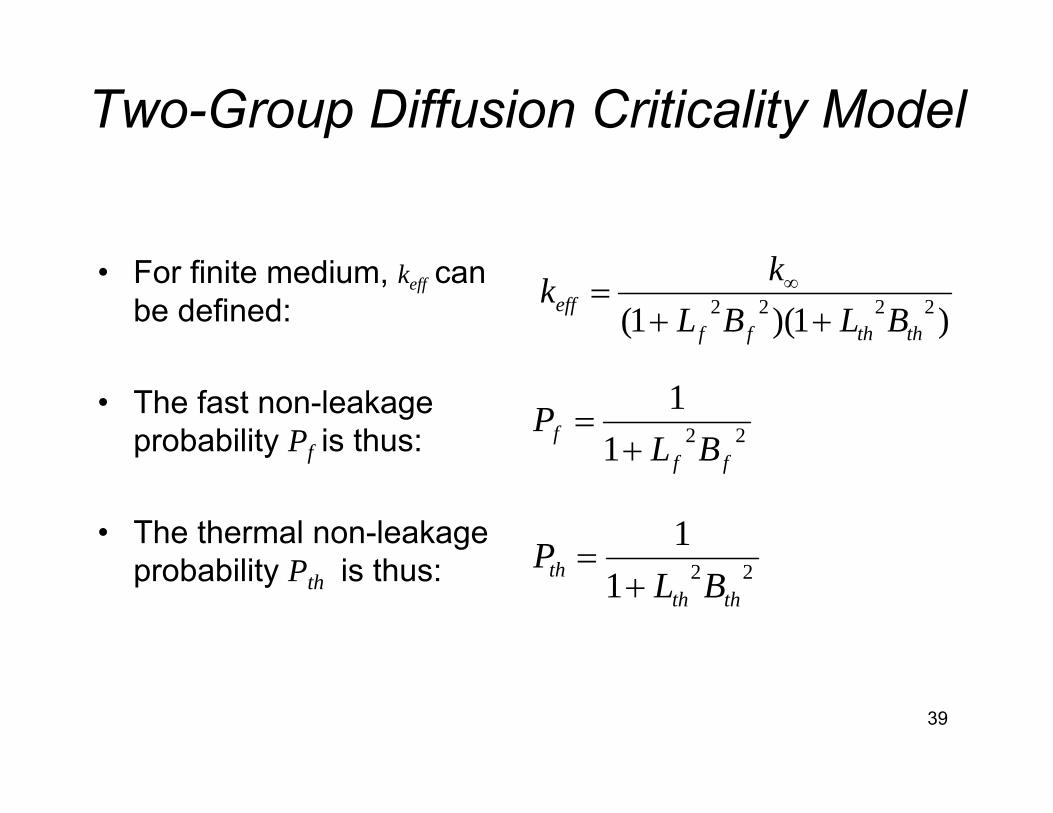
One-Group Diffusion Criticality Model
• For finite medium, keff
can be defined:
• The thermal non-leakage probability Pthis thus:
221 BL
kkeff
+∞
=
2211
BLPth +
=
32
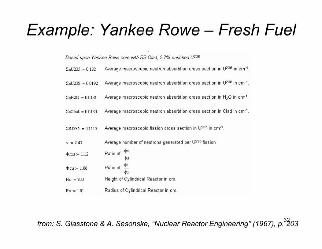
Example: Yankee Rowe – Fresh Fuel
from: S. Glasstone & A. Sesonske, “Nuclear Reactor Engineering” (1967), p. 203
33
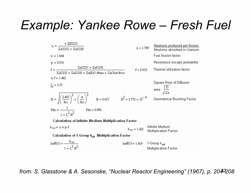
Example: Yankee Rowe – Fresh Fuel
from: S. Glasstone & A. Sesonske, “Nuclear Reactor Engineering” (1967), p. 204-208
34
Two-Group Diffusion Criticality Model
35
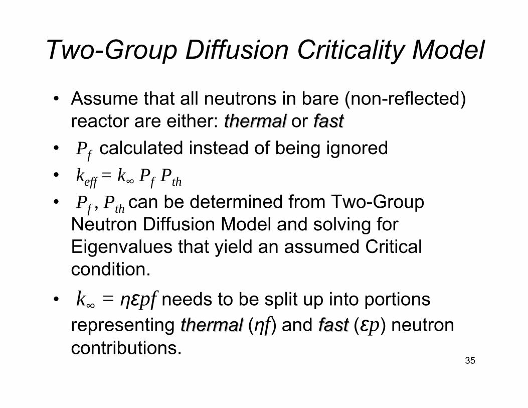
Two-Group Diffusion Criticality Model
• Assume that all neutrons in bare (non-reflected) reactor are either: thermal thermal or fastfast
• Pf calculated instead of being ignored• keff = k∞ Pf Pth
• Pf , Pth can be determined from Two-Group Neutron Diffusion Model and solving for Eigenvalues that yield an assumed Critical condition.
• k∞ = ηεpf needs to be split up into portions representing thermalthermal (ηf) and fastfast (εp) neutron contributions.
36
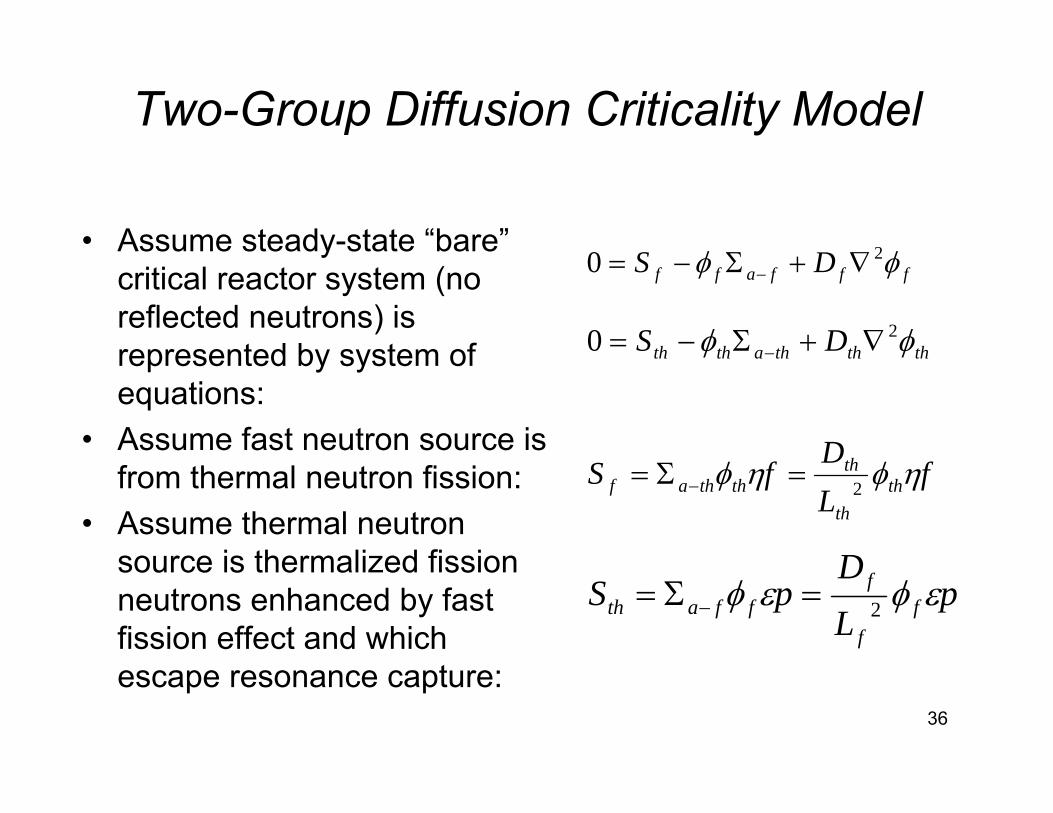
Two-Group Diffusion Criticality Model
• Assume steady-state “bare” critical reactor system (no reflected neutrons) is represented by system of equations:
• Assume fast neutron source is from thermal neutron fission:
• Assume thermal neutron source is thermalized fission neutrons enhanced by fast fission effect and which escape resonance capture:
fffaff DS φφ 20 ∇+Σ−= −
thththathth DS φφ 20 ∇+Σ−= −
fLD
fS thth
thththaf ηφηφ 2=Σ= −
pLD
pS ff
fffath εφεφ 2=Σ= −
37
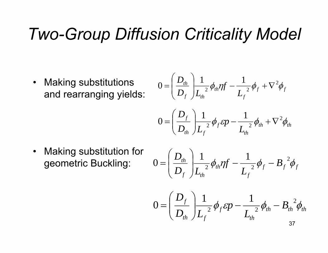
Two-Group Diffusion Criticality Model
• Making substitutions and rearranging yields:
• Making substitution for geometric Buckling:
fff
ththf
th
Lf
LDD φφηφ 2
22110 ∇+−⎟
⎟⎠
⎞⎜⎜⎝
⎛=
ththth
ffth
f
Lp
LDD
φφεφ 222
110 ∇+−⎟⎟⎠
⎞⎜⎜⎝
⎛=
ffff
ththf
th BL
fLD
D φφηφ 222
110 −−⎟⎟⎠
⎞⎜⎜⎝
⎛=
thththth
ffth
f BL
pLD
Dφφεφ 2
22110 −−⎟⎟
⎠
⎞⎜⎜⎝
⎛=
38
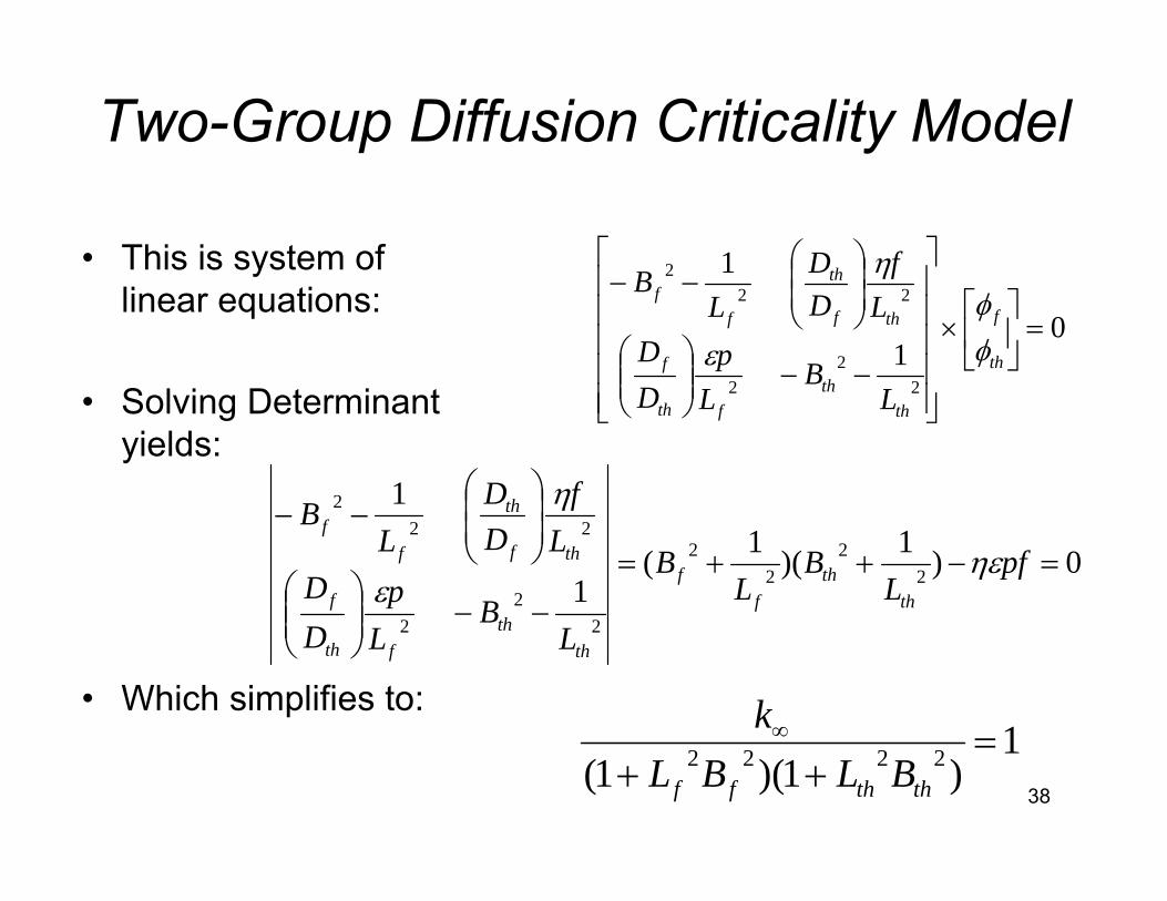
Two-Group Diffusion Criticality Model
• This is system of linear equations:
• Solving Determinant yields:
• Which simplifies to:
01
1
22
2
222
=⎥⎦
⎤⎢⎣
⎡×
⎥⎥⎥⎥⎥
⎦
⎤
⎢⎢⎢⎢⎢
⎣
⎡
−−⎟⎟⎠
⎞⎜⎜⎝
⎛
⎟⎟⎠
⎞⎜⎜⎝
⎛−−
th
f
thth
fth
f
thf
th
ff
LB
Lp
DD
Lf
DD
LB
φφ
ε
η
0)1)(1(1
1
22
22
22
2
222
=−++=
−−⎟⎟⎠
⎞⎜⎜⎝
⎛
⎟⎟⎠
⎞⎜⎜⎝
⎛−−
pfL
BL
B
LB
Lp
DD
Lf
DD
LB
thth
ff
thth
fth
f
thf
th
ff
ηεε
η
1)1)(1( 2222 =
++∞
ththff BLBLk
39
Two-Group Diffusion Criticality Model
• For finite medium, keff can be defined:
• The fast non-leakage probability Pf is thus:
• The thermal non-leakage probability Pth is thus:
)1)(1( 2222ththff
eff BLBLkk
++= ∞
2211
fff BL
P+
=
2211
ththth BL
P+
=

40
Two-Group Criticality Model – Example
• Thermal multiplication factor: η =1.65• Fast fission factor: ε = 1.02• Resonance escape factor: p = 0.87• Thermal utilization factor: f = 0.71
• k∞ = ηεpf = (1.65)(1.02)(0.87)(0.71) = 1.0396
• Fast non-leakage factor: Pf = 0.98• Thermal non-leakage factor: Pth = 0.99
• keff = k∞ Pf Pth = (1.0396)(0.97)(0.99) = 1.008
41
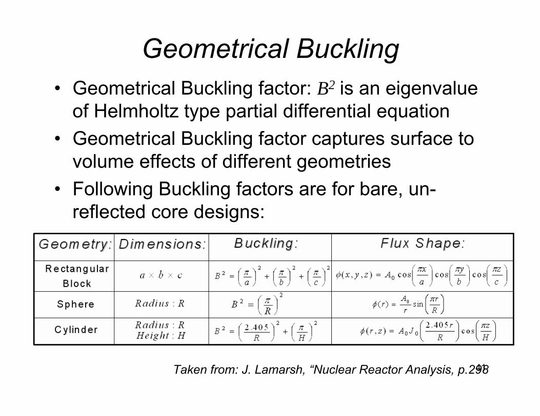
Geometrical Buckling• Geometrical Buckling factor: B2 is an eigenvalue
of Helmholtz type partial differential equation• Geometrical Buckling factor captures surface to
volume effects of different geometries• Following Buckling factors are for bare, un-
reflected core designs:
Taken from: J. Lamarsh, “Nuclear Reactor Analysis, p.298
42
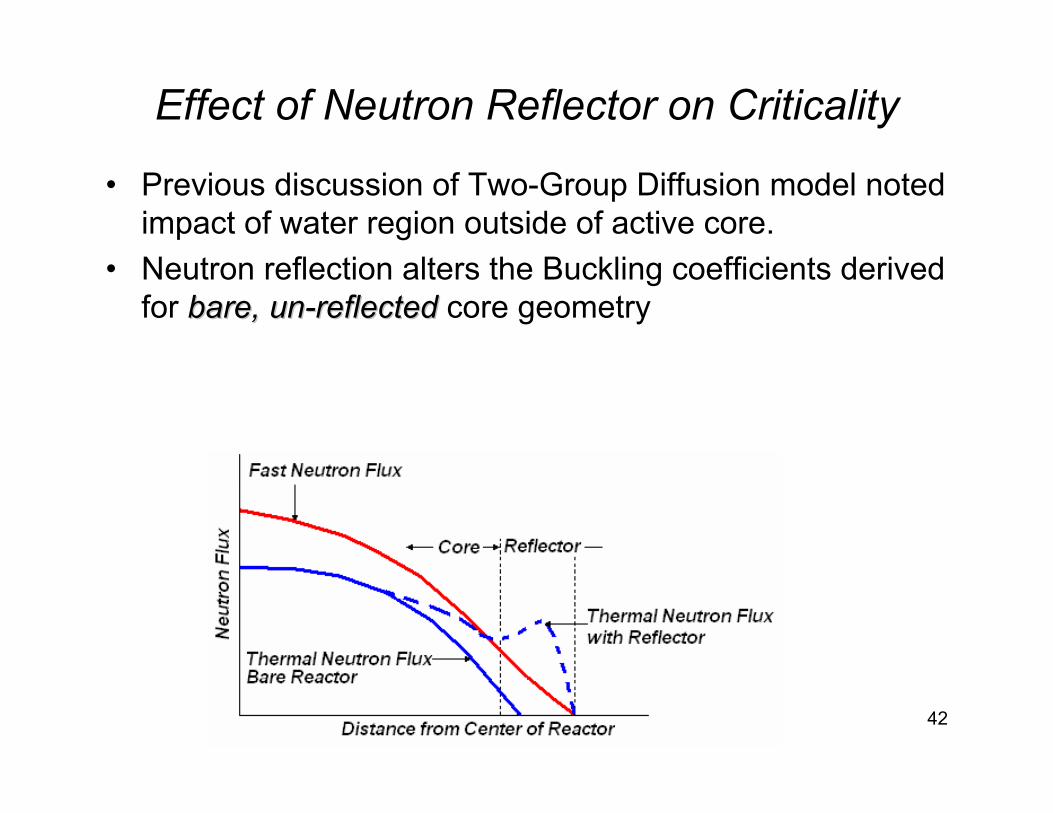
Effect of Neutron Reflector on Criticality
• Previous discussion of Two-Group Diffusion model noted impact of water region outside of active core.
• Neutron reflection alters the Buckling coefficients derived for bare,bare, unun--reflectedreflected core geometry
43
Summary Thoughts on Criticality Evaluation:• Subcriticality, Criticality, Supercriticality conditions are
based upon overall “keff” • Fuel enrichment, bundle geometry, Uranium to Water
ratio directly influences: k∞• Fresh fuel bundles (neglecting impacts of poisons or
control rods) generally have range of k∞ ~ 1.2 or higher to provide fuel for multiyear power operation
• Overall geometry of core (height, radius), reflector region impact fast and thermal non-leakage probabilities and thus: keff
• Classical methods described, reflect correct trends, BUT:• Actual core design process is computer code intensive