super-speed maglev train system *se-jun park , won … · super-speed maglev trains system...
TRANSCRIPT

The 2012 World Congress on Advances in Civil, Environmental, and Materials Research (ACEM’ 12)Seoul, Korea, August 26-30, 2012
A study on thermal deformation of concrete tube structures for super-speed maglev train system
*Se-Jun Park1), Won-Ho Heo2), Ki-Yong Ko3) and Sang-Hyo Kim4)
1), 2), 4) School of Civil and Environmental Engineering, Yonsei University,
Seoul 120-749, Korea 3)Samwhan corporation architects, Seoul 110-742, Korea
ABSTRACT
This paper presents a preliminary study for thermal behavior of concrete tube structures for super-speed tube railway systems. When the concrete tube structures are installed in ground and bridge area, solar radiation induces non-uniform temperature distribution in the tube section depending on the shape of structure and shadows cast on it. So it may cause the thermal deflection on the tube structure, and affects the running stability of maglev train. Therefore it is required to predict and control the thermal behavior of tube structure, which is needed to maintain air-tightness. For the analysis, a method of predicting the 3-dimensional temperature distribution of concrete tube structure was developed. It uses a theoretical solar radiation energy equation together with a commercial FEM program. The thermal behavior of the concrete tube structure was examined using the developed method, while taking into consideration the diverse range of azimuth angles and geometrical shape. From the result of the study, it has been shown that the temperature changes due to solar radiation can be enough to affect the concrete tube structure. And in the same solar radiation conditions, thermal deflection of tube and running stabilities of maglev train were influenced by the number of span, span length and the type of supports of tube structure. 1. INTRODUCTION Super-speed tube train technology involves enclosing rail tracks in concrete tube structures and creating vacuum or partial vacuum state to minimize air resistance, allowing trains to achieve greater speeds at given power. Concrete tube structures for
1) Graduate Student, Ph.D. candidate 2) Graduate Student 3) Engineer 4) Professor
super-speed maglev trains system constructed on terrestrial or bridge sections are subject to structural deformation from environmental factors, such as train’s weight and solar radiation. Therefore, taking account the properties of the closed tube system that must maintain air-tightness and the running characteristics of the super-speed maglev train, which are affected by deformation of the railroad track, it is necessary to predict and control concrete tube structure’s deformation. In order to maintain air-tightness, deformation of the joint area caused by concrete tube structure’s deformation needs to be restrained to within a specific range by selecting a support scheme appropriate for the deformation characteristics according to the type of the concrete tube structure. In this study, among various environmental factors, solar radiation, atmosphere temperature, and wind speed are taken into account to predict the temperature distribution of the concrete tube structure based on numerical analysis and evaluate the amount of deformation. In addition, deformation of end-span is calculated to propose the conditions of the expansion joint required to maintain air-tightness in the concrete tube structures. 2. METHODS FOR PREDICTING TEMPERATURE DISTRIBUTION ON CONCRETE TUBE STRUCTURE CAUSED BY SOLAR RADIATION 2.1 Typical cross-section and solar radiation conditions With the research in its conceptual state, the cross-section of the vacuum tube
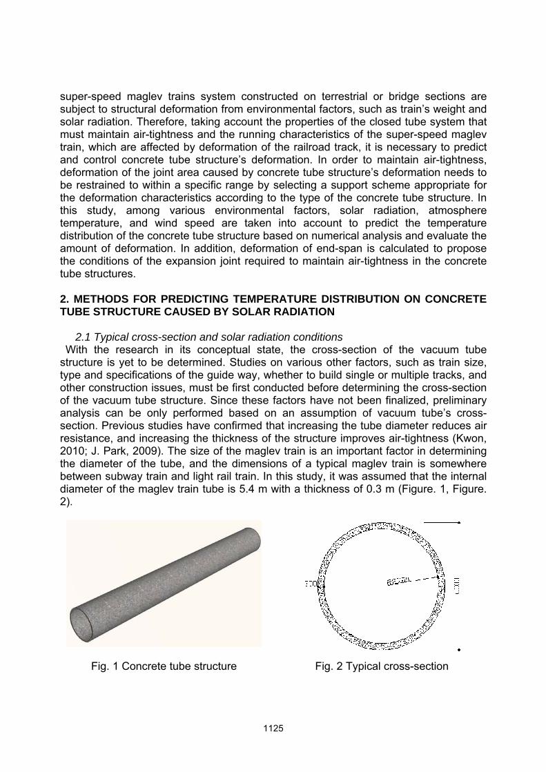
structure is yet to be determined. Studies on various other factors, such as train size, type and specifications of the guide way, whether to build single or multiple tracks, and other construction issues, must be first conducted before determining the cross-section of the vacuum tube structure. Since these factors have not been finalized, preliminary analysis can be only performed based on an assumption of vacuum tube’s cross-section. Previous studies have confirmed that increasing the tube diameter reduces air resistance, and increasing the thickness of the structure improves air-tightness (Kwon, 2010; J. Park, 2009). The size of the maglev train is an important factor in determining the diameter of the tube, and the dimensions of a typical maglev train is somewhere between subway train and light rail train. In this study, it was assumed that the internal diameter of the maglev train tube is 5.4 m with a thickness of 0.3 m (Figure. 1, Figure. 2).
Fig. 1 Concrete tube structure Fig. 2 Typical cross-section

Solar radiation significantly varies according to the location of the concrete tube
structure. In this section, the amount of solar radiation is determined to analyze the temperature behaviour of the concrete tube structure. The solar radiation data was obtained from Incheon KMA. From the solar radiation data of 2008, days of sunny and bright weather with clear skies were selected for analysis. Since the amount of solar radiation is proportional to the amount of deformation, taking into account the duration of sunshine, solar radiation was not measured between 6 and 7 AM and between 7 and 8 PM in January, February, March, April, September, October, November and December. From June to August, solar radiation was measured from 6 AM to 8 PM. Solar radiation data from June and July was selected to analyze the temperature distribution of the concrete tube structure. The input values of the variables used for calculating solar radiation energy is shown in Table 1.
Table 1. Data used for calculation of solar radiation energy
Material constants Values
Target structure’s latitude Ø 37.24° (Incheon)
Solar constant Gsc 1,353W/m2
Solar reflectance of ocean surface ρ 0.2
2.2 Temperature prediction method 2.2.1 Calculation of solar radiation energy on the typical cross-section
In analyzing the rail track deformation in the concrete tube structure, a typical cross-section was selected and performed 2D thermal transfer analysis to obtain the temperature distribution of the cross-section. In order to predict temperature distribution, the solar energy calculation program for bridge section (Yeo, 2003) was used, which calculates the solar radiation energy introduced to tube’s cross-section as a function of solar azimuth angle and declination from equations. It verified by selecting cross-sections in north-south and east-west directions, but only the results concerning the north-south cross-section would be presented in this study because it was affected more significantly by solar radiation. Therefore, if the concrete tube structure has no variation of the cross-section in the length direction, it was assumed that the two ends of the concrete tube structure were in north and south directions for the solar azimuth angle of the typical cross-section. The developed solar radiation energy calculation program is constructed based on theoretical equations; it divides and calculates beam radiation, diffuse radiation, and ground reflected radiation, and applied them as loads in thermal transfer analysis. Declination is the angle between the concrete tube structure exterior to which solar radiation energy is introduced and the horizontal plane; a declination of 0° indicates a horizontal plane, and a declination of 180° means that the concrete tube structure’s external plane is pointed toward the ground. Ground reflected radiation has greatest effects on bottom plane of the lower flange with declination of 180° and on the bottom plane of the cantilever unit with declination close to 180°. Beam radiation is an important factor that causes uneven temperature distribution, and the
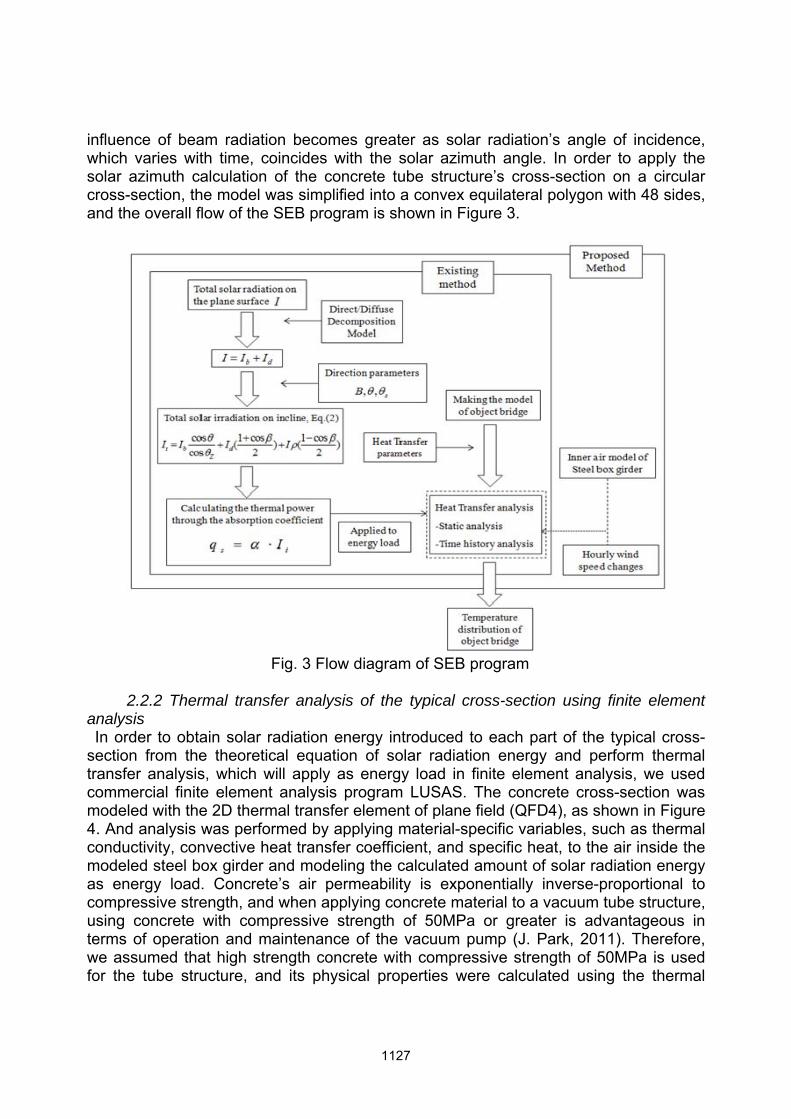
influence of beam radiation becomes greater as solar radiation’s angle of incidence, which varies with time, coincides with the solar azimuth angle. In order to apply the solar azimuth calculation of the concrete tube structure’s cross-section on a circular cross-section, the model was simplified into a convex equilateral polygon with 48 sides, and the overall flow of the SEB program is shown in Figure 3.
Fig. 3 Flow diagram of SEB program
2.2.2 Thermal transfer analysis of the typical cross-section using finite element
analysis In order to obtain solar radiation energy introduced to each part of the typical cross-
section from the theoretical equation of solar radiation energy and perform thermal transfer analysis, which will apply as energy load in finite element analysis, we used commercial finite element analysis program LUSAS. The concrete cross-section was modeled with the 2D thermal transfer element of plane field (QFD4), as shown in Figure 4. And analysis was performed by applying material-specific variables, such as thermal conductivity, convective heat transfer coefficient, and specific heat, to the air inside the modeled steel box girder and modeling the calculated amount of solar radiation energy as energy load. Concrete’s air permeability is exponentially inverse-proportional to compressive strength, and when applying concrete material to a vacuum tube structure, using concrete with compressive strength of 50MPa or greater is advantageous in terms of operation and maintenance of the vacuum pump (J. Park, 2011). Therefore, we assumed that high strength concrete with compressive strength of 50MPa is used for the tube structure, and its physical properties were calculated using the thermal

physical properties of high strength concrete proposed by Kodur et al. (2004).
8 9 10 11 12 13 14 15 16Time (h)
20
25
30
35
40
45
50
55
60
65
70
75
80
Tem
pera
ture
(0 C)
A(June)B(June)A(July)B(July)
Fig. 4 Finite element model of the cross-section
Fig. 5 Temperature variations on the cross-section according to time
2.2.3 Analytical results
In this section, we shall predict the temperature distribution of the typical cross-section using Incheon KMA’s solar radiation data for June and July of 2008 and analyse the hourly temperature variation of each part on the typical cross-section. We applied solar radiation data measured between 8 AM to 4 PM when solar radiation was greater than 1MJ/m2. Figure 5 shows the temperature variation on the cross-section of the concrete tube structure according to time. Data from two points on the concrete tube structure’s cross-section—A, which is most exposed to solar radiation, and B, which is in the shadow— are shown for comparison. The analytical results of the temperature distribution from solar radiation in June and July display almost similar outcome. Temperature in July consistently increases, and due to abrupt increase of solar radiation in June, temperature between 1 and 2 PM is drastically increased. While temperature in July is higher than in June, the temperature difference between points A and B was somewhat greater at 2 PM in June. We used the outcome of the temperature distribution analysis using solar radiation data of June as 3D temperature load because we believed that it would result in greater deformation of the concrete tube structure. Cross-sections at both ends showed highest temperatures at 2 PM, which we believe was caused by the fact exposure to solar radiation is longest and the amount of solar radiation is greatest at 2PM. The analytical result was used as the temperature load in finite element analysis, which was expanded from 2D to 3D. 3. EVALUATION OF TEMPERATURE DEFORMATION OF CONCRETE TUBE STRUCTURE In this chapter, 3D finite element analysis was performed on the entire concrete tube
structure by applying the temperature distribution of the typical cross-section analyzed with 2D temperature distribution prediction technique as the temperature load. Furthermore, deformation of end-span was evaluated under various conditions by taking into account variations in parameters such as the span length, rail installation location, and support configuration of the tube structure.
3.1 Modeling of the concrete tube structure Exposed to the natural environment, a concrete tube structure is affected not only by
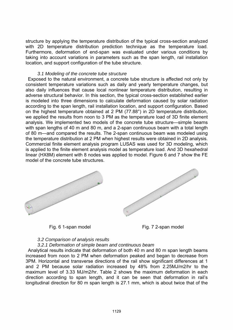
consistent temperature variations such as daily and yearly temperature changes, but also daily influences that cause local nonlinear temperature distribution, resulting in adverse structural behavior. In this section, the typical cross-section established earlier is modeled into three dimensions to calculate deformation caused by solar radiation according to the span length, rail installation location, and support configuration. Based on the highest temperature obtained at 2 PM (77.88°) in 2D temperature distribution, we applied the results from noon to 3 PM as the temperature load of 3D finite element analysis. We implemented two models of the concrete tube structure—simple beams with span lengths of 40 m and 80 m, and a 2-span continuous beam with a total length of 80 m—and compared the results. The 2-span continuous beam was modeled using the temperature distribution at 2 PM when highest results were obtained in 2D analysis. Commercial finite element analysis program LUSAS was used for 3D modeling, which is applied to the finite element analysis model as temperature load. And 3D hexahedral linear (HX8M) element with 8 nodes was applied to model. Figure 6 and 7 show the FE model of the concrete tube structures.
Fig. 6 1-span model Fig. 7 2-span model
3.2 Comparison of analysis results 3.2.1 Deformation of simple beam and continuous beam
Analytical results indicate that deformation of both 40 m and 80 m span length beams increased from noon to 2 PM when deformation peaked and began to decrease from 3PM. Horizontal and transverse directions of the rail show significant differences at 1 and 2 PM because solar radiation increased by 48% from 2.25MJ/m2/hr to the maximum level of 3.33 MJ/m2/hr. Table 2 shows the maximum deformation in each direction according to span length, and it can be seen that deformation in rail’s longitudinal direction for 80 m span length is 27.1 mm, which is about twice that of the

40 m span length, which is 13.7 mm. Since a longer span length is subject to greater solar radiation, adequate span length and structure configuration should be chosen by taking into account environmental factors such as site conditions and the amount of solar radiation. In Table 3, there is a significant difference between deformations in the transverse
direction (DY) and the horizontal direction (DX) of the 80 m simple beam and the 80 m 2-span continuous beam. Unlike transverse and horizontal directions, however, deformation in the longitudinal direction of 80 m 2-span continuous beam was greater than that of the 80 m simple beam. This is because the simple beam showed a more of an upward protruding deformation in shape, resulting in relatively small deformation in the longitudinal direction. However, from the super-speed maglev train’s running aspect, deformation in transverse and horizontal directions are likely to have more effect than longitudinal deformation, and the 80 m 2-span continuous beam showed less overall deformation than the 40 m simple beam. Therefore, in terms of the support configuration of the concrete tube structure configuration, continuous beams would be less affected by solar radiation than simple beams and more favorable for safe operation of the super-speed maglev train system.
Table 2. Maximum deformation in 3 directions according to span length
Span length
Maximum deformation (at 2 PM)
DX (mm) DY (mm) DZ (mm)
Simple beam
40m 6.7 9.9 13.7
80m 30.8 43.7 27.1
Table 3. Maximum deformation in 3 directions according to support type
Span length
Maximum deformation (at 2 PM)
DX (mm) DY (mm) DZ (mm)
Simple beam 80m 30.8 43.7 27.1
Continuous beam 40m+40m 4.6 4.6 34.1
Figure 8 shows deformations in the transverse direction of the continuous 40 m simple
beam, 80 m simple beam, and 80 m 2-span continuous beam. In the case of the continuous 40 m simple beam, if the super-speed maglev train becomes upward convex as shown in Figure 4.15(a), the train might not run smoothly in joint sections. However, since super-speed maglev train rail is installed inside the concrete tube structure, the train may be able to operate without being directly influenced by the tube structure. The 40 m simple beam and the 80 m 2-span continuous beam showed deformations of 9.9 mm and 4.6 mm, respectively, in the transverse direction at the
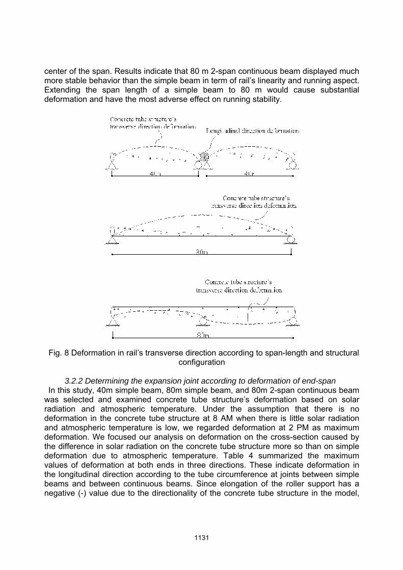
center of the span. Results indicate that 80 m 2-span continuous beam displayed much more stable behavior than the simple beam in term of rail’s linearity and running aspect. Extending the span length of a simple beam to 80 m would cause substantial deformation and have the most adverse effect on running stability.
Fig. 8 Deformation in rail’s transverse direction according to span-length and structural configuration
3.2.2 Determining the expansion joint according to deformation of end-span
In this study, 40m simple beam, 80m simple beam, and 80m 2-span continuous beam was selected and examined concrete tube structure’s deformation based on solar radiation and atmospheric temperature. Under the assumption that there is no deformation in the concrete tube structure at 8 AM when there is little solar radiation and atmospheric temperature is low, we regarded deformation at 2 PM as maximum deformation. We focused our analysis on deformation on the cross-section caused by the difference in solar radiation on the concrete tube structure more so than on simple deformation due to atmospheric temperature. Table 4 summarized the maximum values of deformation at both ends in three directions. These indicate deformation in the longitudinal direction according to the tube circumference at joints between simple beams and between continuous beams. Since elongation of the roller support has a negative (-) value due to the directionality of the concrete tube structure in the model,
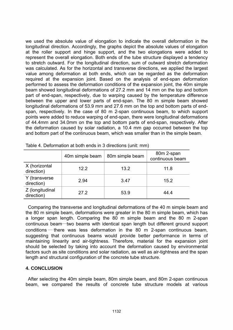
we used the absolute value of elongation to indicate the overall deformation in the longitudinal direction. Accordingly, the graphs depict the absolute values of elongation at the roller support and hinge support, and the two elongations were added to represent the overall elongation. Both ends of the tube structure displayed a tendency to stretch outward. For the longitudinal direction, sum of outward stretch deformation was calculated. As for the horizontal and transverse directions, we applied the largest value among deformation at both ends, which can be regarded as the deformation required at the expansion joint. Based on the analysis of end-span deformation performed to assess the deformation conditions of the expansion joint, the 40m simple beam showed longitudinal deformations of 27.2 mm and 14 mm on the top and bottom part of end-span, respectively, due to warping caused by the temperature difference between the upper and lower parts of end-span. The 80 m simple beam showed longitudinal deformations of 53.9 mm and 27.6 mm on the top and bottom parts of end-span, respectively. In the case of 80 m 2-span continuous beam, to which support points were added to reduce warping of end-span, there were longitudinal deformations of 44.4mm and 34.0mm on the top and bottom parts of end-span, respectively. After the deformation caused by solar radiation, a 10.4 mm gap occurred between the top and bottom part of the continuous beam, which was smaller than in the simple beam.
Table 4. Deformation at both ends in 3 directions (unit: mm)
40m simple beam 80m simple beam 80m 2-span continuous beam
X (horizontal direction) 12.2 13.2 11.8
Y (transverse direction) 2.94 3.47 15.2
Z (longitudinal direction) 27.2 53.9 44.4
Comparing the transverse and longitudinal deformations of the 40 m simple beam and
the 80 m simple beam, deformations were greater in the 80 m simple beam, which has a longer span length. Comparing the 80 m simple beam and the 80 m 2-span continuous beam—two beams with identical span length but different ground support conditions— there was less deformation in the 80 m 2-span continuous beam, suggesting that continuous beams would provide better performance in terms of maintaining linearity and air-tightness. Therefore, material for the expansion joint should be selected by taking into account the deformation caused by environmental factors such as site conditions and solar radiation, as well as air-tightness and the span length and structural configuration of the concrete tube structure.
4. CONCLUSION After selecting the 40m simple beam, 80m simple beam, and 80m 2-span continuous
beam, we compared the results of concrete tube structure models at various
atmospheric temperatures and solar radiation levels. We also analyzed the deformation in the transverse direction, which significantly affects the running stability of the train. The 40m simple beam and the 80m 2-span continuous beam showed deformation of 9.9mm and 4.6mm, respectively, in the traverse direction from mid-span. Based on the amount of deformation, we believe 80m 2-span continuous beams would produce better performance than simple beams in terms of rail’s linearity and running stability. Extending a simple beam to a span length of 80m is likely to result in substantial deformation and have adverse consequences. And end-span deformation was analyzed to assess the deformation conditions of expansion joints showed. The 40 m simple beam showed longitudinal deformations of 27.2mm and 14.0mm on the top and bottom parts of end-span, respectively. As for the 80m simple beam, longitudinal deformations on the top and bottom parts of end-span were 53.9mm and 27.6mm, respectively. In the case of 80m 2-span continuous beam, to which support points were added to reduce warping of end-span, there were longitudinal deformations of 44.4 mm and 34.0mm on the top and bottom parts of end-span, respectively. After the deformation caused by solar radiation, a 10.4mm gap occurred between the top and bottom parts of the continuous beam, which was smaller than in the simple beam. Therefore, continuous beams would provide better performance when installing expansion joints in terms of maintaining air-tightness.
REFERENCES J. Park, L-H. Kim, S-W. Nam (2011), “Air-tightness Evaluation of Tube structures for
Super-speed Tube Railway Systems: I. Analytical Modeling and Material Test”, Journal of the Korean Society for Railway, Vol. 14, No.2, pp.143-150.
J. Park, I. Yeo (2009), “Air-tightness of Vacuum tube High-Speed Railway System”, Proceeding of the Autumn Conference for Railway, Journal of the Korean Society for Railway, Jeju, Korea.
Kodur V.K.R., Wang T.C., and Cheng F. P. (2004), “Predicting the fire resistance behavior of high strength concrete columns”, Cement and Concrete Composites, Vol. 26, pp.141-153.
Kwon H.B., Kang B.B., Kim B.Y., Lee D.H., Jung H.J. (2010), “Parametric Study on the Aerodynamic Drag of Ultra High-Speed Train in Evacuated Tube – Part 1”, Journal of the Korean Society for Railway, Vol. 13, No.1, pp.44-50.
Yeo Y.G. (2003), “Thermal Behavior of Curved Steel Box Girder Bridge considering Solar Radiation”, M.Sc. Thesis, Yonsei University, Korea.